95-2004 - Car Radio Metra - Free user manual and instructions
Find the device manual for free 95-2004 Metra in PDF.

User questions about 95-2004 Metra
0 question about this device. Answer the ones you know or ask your own.
Ask a new question about this device
Download the instructions for your Car Radio in PDF format for free! Find your manual 95-2004 - Metra and take your electronic device back in hand. On this page are published all the documents necessary for the use of your device. 95-2004 by Metra.
USER MANUAL 95-2004 Metra
INSTALLATION INSTRUCTIONS FOR PART 95-2004
APPLICATIONS
Cadillac
1997-2001 Catera
1996-1999 Deville (Column Shift Only)
95-2004
KIT FEATURES
• DDIN Head Unit Provision
• ISO Stacked Head Unit Provision

natural_image
Interior view of a car air conditioner unit with control panel and fan (no visible text or symbols)KIT COMPONENTS
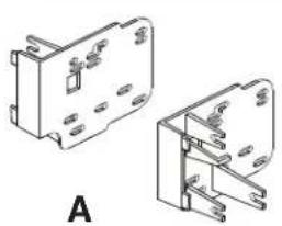
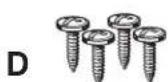
• (A) DDIN Brackets • (B) DDIN Trim Plate • (C) (4) Speed Clips • (4) Phillips Head Screws
natural_image
Technical line drawing of two mechanical components with mounting holes and mounting brackets (no text or symbols)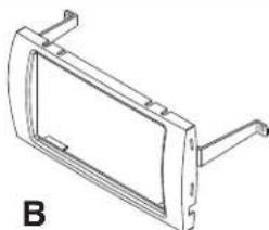
natural_image
Technical line drawing of a mechanical bracket or frame (no text or symbols)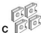
WIRING AND ANTENNA CONNECTIONS (Sold Separately)
HARNESS:
• GMRC-03 - 1997-2002 Cadillac Interface W/O Onstar
• GMOS-06 - 1997-2002 Cadillac Interface W/ Onstar
ANTENNA ADAPTER:
• 40-GM10 - GM Antenna Adapter
TOOLS REQUIRED:
- Phillips Screwdriver - Panel Removal Tool - Small Flat Blade Screwdriver - Cutting Tool
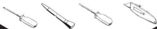
natural_image
Line drawings of four different screwdriver tools (no text or symbols)METRA. THE WORLD'S BEST KITS.™

1-800-221-0932

www.metraonline.com
© COPYRIGHT 2004 METRA ELECTRONICS CORPORATION
TABLE OF CONTENTS
Dash Disassembly
1997-2001 Cadillac Catera 1
1996-1999 Cadillac Deville (Column Shift Only) 1
Kit Preparation
1997-2001 Cadillac Catera 2
1996-1999 Cadillac Deville (Column Shift Only) 2
Kit Assembly
1997-2001 Cadillac Catera / 1996-1999 Cadillac Deville (Column Shift Only)
DDIN Head Unit Provision 3
ISO Stacked Head Unit Provision 3

KNOWLEDGE IS POWER
Enhance your installation and fabrication skills by enrolling in the most recognized and respected mobile electronics school in our industry. Log onto www.installerinstitute.com or call 800-354-6782 for more information and take steps toward a better tomorrow.

text_image
MP CP mobile electronics certified professionalMetra recommends using MECP certified technicians.
1997-2001 CADILLAC CATERA
1 Disconnect the negative battery terminal to prevent an accidental short circuit.
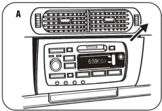
2 Remove (1) Phillips head screw from inside the ashtray and remove ash-tray. (Figure A)
3 Remove screw covers from the radio trim panel. Remove traction control and hazard switch covers. Then remove switches by depressing tabs and pulling outward. (Figure B)
4 Remove (4) Phillips head screws from behind covers and ashtray.
5 Remove radio trim panel and unplug any remaining harnesses from the panel. (Figure C)
6 Remove (2) Phillips head screws securing the radio. Unplug and remove the radio.

natural_image
Top-down view of a car infotainment system showing dashboard, air conditioner, and control panel (no text or labels)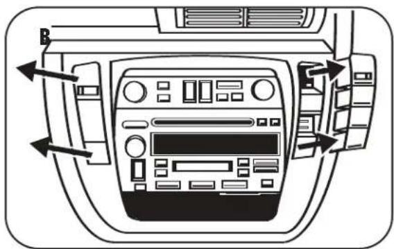
natural_image
Interior view of a car dashboard with air vent and control panel (no text or symbols visible)
natural_image
Interior view of a car dashboard with control panel and buttons (no text or symbols visible)1996-1999 CADILLAC DEVILLE
1 Disconnect the negative battery terminal to prevent an accidental short circuit.
2 Unsnap and remove radio trim panel. (Open glove box to access.) (Figure A)
3 Pinch the side clips to disengage radio. Unplug and remove radio.
text_image
A 6.598:501997-2001 CADILLAC CATERA
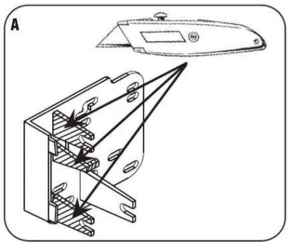
1 Cut and remove the three shaded tabs on both brackets. (Figure A)
natural_image
Technical line drawing of a mechanical component with internal parts and directional arrows (no text or symbols)1996-1999 CADILLAC DEVILLE
1 Cut and remove the shaded tab from both brackets, and both of the tabs on the trim plate. (Figure B)
2 Install (4) speed clips into the sub-dash mounting positions. (Figure C)

natural_image
Technical line drawing of a mechanical housing assembly with labeled components (no text or symbols)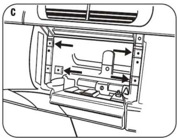
natural_image
Diagram of a car interior showing airflow or traffic flow through a vehicle intake and outlet (no text or symbols)DOUBLE DIN / STACKED ISO DIN HEAD UNIT PROVISIONS
1 Locate the factory wiring harness in the dash. Metra recommends using the proper mating adapter from Metra or AXXESS. Re-connect the negative battery terminal and test the unit for proper operation.
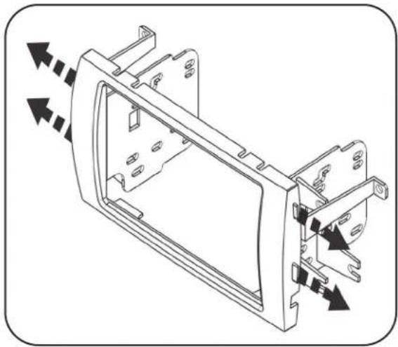
2 Attach the Double DIN brackets to the inside edge of the Double DIN trim plate. (Figure A)
3 Slide the bracket/radio housing assembly over the Double DIN head unit and secure using the screws supplied with the radio. (Figure B)
4 Reassemble dash in reverse order of disassembly.
natural_image
Technical line drawing of a mechanical housing component with directional arrows indicating movement (no text or symbols)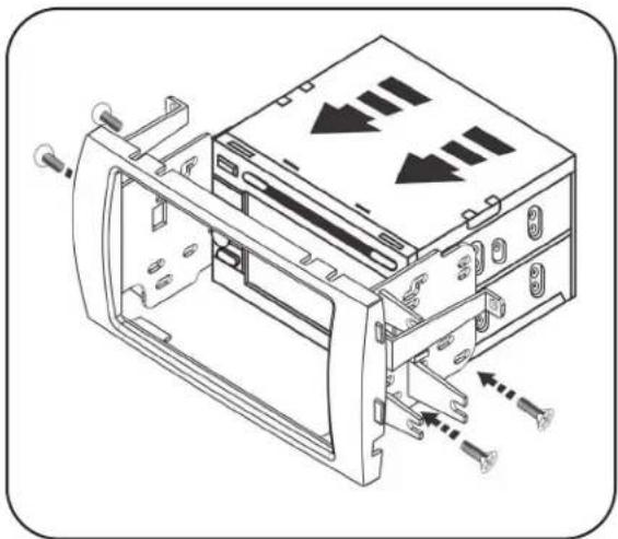
natural_image
Technical line drawing of a computer drive bay with screw fasteners and directional arrows indicating motion (no text or symbols)INST95-2004
METRA. THE WORLD'S BEST KITS.™

1-800-221-0932

www.metraonline.com
REV. 12/01/09
© COPYRIGHT 2004 METRA ELECTRONICS CORPORATION
INST95-2004