
91-3520P - Car Radio Metra - Free user manual and instructions
Find the device manual for free 91-3520P Metra in PDF.

| Product Type | Car Radio Installation Kit |
| Brand | Metra |
| Model | 91-3520P |
| Compatible Vehicles | Pontiac (various models) |
| Kit Type | DIN and Shaft Receiver |
| Included Components | Kit Frame, Support Tray, (2) Right Mounting Brackets, (4) 1/4" Hex Screws, (2) Studs, (2) 3/8" Nuts |
| Radio Opening Size | DIN (approx. 7 x 2 inches) |
| Material | Plastic and Metal |
| Color | Black |
| Installation Method | Replaces factory radio, uses existing dash openings |
| Tools Required | 9/32" socket, utility knife, screwdriver |
| Safety Precautions | Disconnect negative battery cable before installation |
| Dimensions (Kit Frame) | Approx. 7.2 x 4.5 x 3 inches |
| Weight | Approx. 0.5 lbs (0.23 kg) |
| Power Source | Vehicle's electrical system (12V DC) |
| Warranty | 1 year limited warranty |
| Mounting Hardware Included | Yes |
| Noise Reduction | Not applicable |
| Water Resistance | Not specified (indoor use only) |
| Operating Temperature | -20°C to 60°C |
Frequently Asked Questions - 91-3520P Metra
User questions about 91-3520P Metra
0 question about this device. Answer the ones you know or ask your own.
Ask a new question about this device
Download the instructions for your Car Radio in PDF format for free! Find your manual 91-3520P - Metra and take your electronic device back in hand. On this page are published all the documents necessary for the use of your device. 91-3520P by Metra.
USER MANUAL 91-3520P Metra
Before starting, compare items on your invoice with items received. Carefully check through packaging material.
If an item is missing, please call:
Crutchfield at 1-888-955-6000
Pontiac
Revision 10/31/03
Parts Supplied:

natural_image
Isometric line drawing of a rectangular enclosure with internal components and mounting holes (no text or symbols)Kit Frame

Support Tray


(4) 1/4" Hex Screws


Right
Mounting Brackets
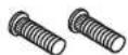
(2) Studs

(2) 3/8" Nuts
Kit assembly instructions are on the following pages.
Factory Radio Removal:

- Disconnect negative battery cable to prevent any electrical short.
- Move column shift down for better access to receiver trimpanel. Tilt steering wheel to lowest position.
- Pull out edges of receiver trimpanel to release retaining clips. If SSEi version: Remove knob and disconnect sub gain switch (Inset). Remove trimpanel.
- Remove three (3) 9/32" screws securing radio to dash.
- Pull out radio, disconnect and remove.


CRUTCHFIELD®
Copyright 2003 Crutchfield Corporation
Installation Kit
120 91-3520P
Pontiac
DIN Receiver Assembly
- Press posts on trimplate into holes on kit frame to snap parts together and secure with hex screws (Figure 1).
- Use a utility knife to cut out shaft supports in trimplate to create a DIN opening (Figure 2).
- Push clips on support tray into slots on rear of kit frame to secure (Figure 1).
- Secure right and left mounting brackets to sides of kit frame with studs and nuts supplied (Figure 1).
- Remove DIN sleeve from receiver and slide into opening in trimplate. Secure sleeve to trimplate by bending the securing tabs (Figure 3).
- Slide receiver into sleeve/kit assembly.


CRUTCHFIELD®
Copyright 2003 Crutchfield Corporation
Installation Kit
120 91-3520P
Pontiac
Shaft Receiver Assembly
- Press posts on trimplate into holes on kit frame to snap parts together and secure with hex screws (Figure 1).
- Push clips on support tray into slots on rear of kit frame to secure (Figure 1).
- Secure right and left mounting brackets to sides of kit assembly with studs and nuts supplied (Figure 1).
- Choose the proper spacers (supplied with your order) to allow receiver nosepiece to extend 1/8" to 1/4" beyond face of trimplate (Figure 2).
- Insert receiver shafts (with spacers in place) through openings in trimplate. Secure receiver and faceplate with shaftnuts supplied with receiver.
- Attach control knobs.


CRUTCHFIELD®
Copyright 2003 Crutchfield Corporation

Brand : Metra
Model : 91-3520P
Category : Car Radio