VE1901AEUT-AT-U - Commutateur AV ATEN - Free user manual and instructions
Find the device manual for free VE1901AEUT-AT-U ATEN in PDF.

User questions about VE1901AEUT-AT-U ATEN
0 question about this device. Answer the ones you know or ask your own.
Ask a new question about this device
Download the instructions for your Commutateur AV in PDF format for free! Find your manual VE1901AEUT-AT-U - ATEN and take your electronic device back in hand. On this page are published all the documents necessary for the use of your device. VE1901AEUT-AT-U by ATEN.
USER MANUAL VE1901AEUT-AT-U ATEN
Compliance Statements
FEDERAL COMMUNICATIONS COMMISSION INTERFERENCE STATEMENT
This equipment has been tested and found to comply with the limits for a Class A digital device, pursuant to Part 15 of the FCC Rules. These limits are designed to provide reasonable protection against harmful interference when the equipment is operated in a commercial environment. This equipment generates, uses, and can radiate radio frequency energy and, if not installed and used in accordance with the instruction manual, may cause harmful interference to radio communications. Operation of this equipment in a residential area is likely to cause harmful interference in which case the user will be required to correct the interference at his own expense.
The device complies with Part 15 of the FCC Rules. Operation is subject to the following two conditions: (1) this device may not cause harmful interference, and (2) this device must accept any interference received, including interference that may cause undesired operation.
FCC Caution
Any changes or modifications not expressly approved by the party responsible for compliance could void the user's authority to operate this equipment.
Warning
Operation of this equipment in a residential environment could cause radio interference.
Achtung
Industry Canada Statement
This Class A digital apparatus complies with Canadian ICES-003.
CAN ICES-003 (A) / NMB-003 (A)
RoHS
This product is RoHS compliant.
About this Manual
This user manual is provided to help you get the most from the VE1901AEUT / VE1901AUST unit. It covers all aspects of installation, configuration, and operation. An overview of the information found in the manual is provided below.
Chapter 1, Introduction introduces you to the VE1901AEUT / VE1901AUST DisplayPort HDBaseT-Lite Transmitter with EU / US Wall Plate / PoH. Its purpose, features, installation considerations, and panel components are presented and described.
Chapter 2, Hardware Setup describes the steps that are necessary to quickly and safely set up your installation.
Chapter 3, Operation explains the Long Reach Mode and limitations, and how to set up the input detection mode using the a pushbutton and RS-232 commands.
An Appendix provides a list of safety instructions and precautions, contact information for ATEN technical support, product specifications, and other technical information.
Note:
- Read this manual thoroughly and follow the installation and operation procedures carefully to prevent any damage to the unit or any connected devices.
- ATEN regularly updates its product documentation for new features and fixes. For an up-to-date VE1901AEUT / VE1901AUST documentation, visit http://www.aten.com/global/en/
Conventions
This manual uses the following conventions:
MonospacedIndicates text that you should key in.
[] Indicates keys you should press. For example, [Enter] means to press the Enter key. If keys need to be chorded, they appear together in the same bracket with a plus sign between them: [Ctrl+Alt].
- Numbered lists represent procedures with sequential steps.
◆ Bullet lists provide information, but do not involve sequential steps.
Indicates selecting the option (on a menu or dialog box, for example), that comes next. For example, Start > Run means to open the Start menu, and then select Run.

Indicates critical information.
Package Contents
VE1901AEUT
1 VE1901AEUT DisplayPort HDBaseT-Lite Transmitter with EU Wall Plate / PoH
1 5-pin terminal block
1 rubber pad set (4 pcs)
1 faceplate
2 pan head screws
4 PF screws
1 power adapter
1 user instructions*
VE1901AUST
1 VE1901AUST DisplayPort HDBaseT-Lite Transmitter with US Wall Plate / PoH
1 5-pin terminal block
1 faceplate
2 flat head screws
1 power adapter
1 user instructions*
Note: Make sure that all of the components are present and in good order. If anything is missing or was damaged in shipping, contact your dealer.
Product Information
For information about all ATEN products and how they can help you connect without limits, visit ATEN on the Web or contact an ATEN Authorized Reseller. Visit ATEN on the Web for a list of locations and telephone numbers:
| International http://www.aten.com |
| North America http://www.aten-usa.com |
User Information
Online Registration
Be sure to register your product at our online support center:
| International http://eservice.aten.com |
Telephone Support
For telephone support, call this number:
| International 886-2-8692-6959 |
| China 86-400-810-0-810 |
| Japan 81-3-5615-5811 |
| Korea 82-2-467-6789 |
| North America 1-888-999-ATEN ext 4988 |
| 1-949-428-1111 |
User Notice
All information, documentation, and specifications contained in this manual are subject to change without prior notification by the manufacturer. The manufacturer makes no representations or warranties, either expressed or implied, with respect to the contents hereof and specifically disclaims any warranties as to merchantability or fitness for any particular purpose. Any of the manufacturer's software described in this manual is sold or licensed as is. Should the programs prove defective following their purchase, the buyer (and not the manufacturer, its distributor, or its dealer), assumes the entire cost of all necessary servicing, repair and any incidental or consequential damages resulting from any defect in the software.
The manufacturer of this system is not responsible for any radio and/or TV interference caused by unauthorized modifications to this device. It is the responsibility of the user to correct such interference.
The manufacturer is not responsible for any damage incurred in the operation of this system if the correct operational voltage setting was not selected prior to operation. PLEASE VERIFY THAT THE VOLTAGE SETTING IS CORRECT BEFORE USE.
Table of Contents
Compliance Statements ...... ii
About this Manual iv
Conventions ...... v
Package Contents ...... vi
Product Information vii
User Information ...... vii
Online Registration vii
Telephone Support....vii
User Notice . . . . . . . . . . . . . . . . . . . . . . . . . . . . . . . . . . . . . . . . . . . . . . . . . . . . . . . . . . . . . . . . . . . . . . . . . . . . . . . . . . . . . . . viii
Table of Contents ix
1. Introduction
Overview 1
Features 2
Planning the Installation ....3
Requirements 3
Considerations 3
Compatible ATEN Video Extenders 3
Components 4
Front View....4
Rear View 5
Top View 7
2. Hardware Setup
Mounting the VE1901AEUT / VE1901AUST Unit 9
Site Preparation....9
Drawing Screw Site....9
VE1901AEUT Wall Mount 10
VE1901AUST Wall Mount ....11
Connecting the VE1901AEUT / VE1901AUST Unit 12
Terminal Block Connection .... 13
Power Supply Information 14
RS-232 Channel Transmission 15
3. Operation
RS-232 Serial Transmission....17
Bypass. 17
Connecting the Unit with VP1421 18
Appendix
Safety Instructions....19
General 19
Technical Support 21
International 21
North America 21
Specifications 22
Limited Warranty 32
Template Printing 33
Overview
The ATEN VE1901AEUT / VE1901AUST DisplayPort HDBaseT-Lite transmitter delivers 4K signals up to 40 m over a single Cat 5e/6/6a or ATEN 2L-2910 Cat 6 cable, ensuring users to stabilize DisplayPort signal transmission with support of Deep color and embedded HD lossless audio formats. During high-quality video transmission, the transmitter can resist signal interference with the equipped HDBaseT Anti-jamming technology and offer a reliable signal extension.
The VE1901AEUT / VE1901AUST can be easily mounted in a 1-gang junction box with EU / US wall plate, concealing bulky cable setups and presenting needed information in sight. In addition, with built-in PoH (Power over HDBaseT) function, the VE1901AEUT / VE1901AUST receives power supply from a connected PoH PSE supported receiver and streamlines complex power line deployment.
With the share function, the VE1901AEUT / VE1901AUST can remotely switch source when connecting to a compatible receiver, e.g., VP1421, bringing users for more convenient AV extension. This compact transmitter provides a neat and simple installation on walls or tables, enabling users to elegantly immerse their AV applications into any environment. Therefore, the VE1901AEUT / VE1901AUST is ideal for use in meeting rooms, digital educational environments or any application requiring stable high-quality transmission and effortless installation.
Features
◆ Extends DisplayPort signals with superior video quality over a single Cat 5e/6/6a cable or ATEN 2L-2910 Cat 6 cable
◆ 4K up to 40 m
◆ 1080p up to 70 m
Built-in PoH (Power over HDBaseT) function – the VE1901AEUT / VE1901AUST receives power supply from the HDBasT output port
◆ DisplayPort (Deep color, 4K); HDCP compliant
- Designed to mount in a 1-gang junction box with EU / US wall plate
◆ Supports RS-232 channel transmission
- HDBaseT Anti-jamming – resists signal interference during high-quality video transmission using HDBaseT technology
- Share function – the VE1901AEUT / VE1901AUST can remotely switch source when connecting to a compatible receiver, e.g., VP1421
♦ LED indication of device status
◆ Built-in 8KV / 15KV ESD protection
◆ DC jack and PoH for power redundancy
Plug-and-play
Planning the Installation
Requirements
Prepare the following before installing the VE1901AEUT / VE1901AUST unit:
◆ 1 DisplayPort source device
◆ 1 Cat 5e/6/6a or ATEN 2L-2910 Cat 6 cable
Considerations
- To ensure video quality, ATEN recommends using a Cat 5e/6/6a cable.
Note: ATEN recommends using the ATEN 2L-2910 Cat 6 cable for best results.
- The maximum transmission distance varies at different parts of the transmission:
| Connection Interface Resolution Distance | |||
| Computer to the VE1901AEUT / VE1901AUST | DisplayPort 4K | 3 m | |
| The VE1901AEUT / VE1901AUST to a compatible ATEN HDBaseT Receiver | Cat 5e/6 4K 35 m | ||
| Cat 6a 4K 40 m | |||
| A compatible ATEN Video Receiver to the display | DisplayPort (example) | 4K 3 m | |
Note: The maximum transmission distance for 1080p resolution using an ATEN 2L-2910 cable is 70 m.
Compatible ATEN Video Extenders
The VE1901AEUT / VE1901AUST is compatible with a wide range of ATEN HDBaseT video receivers. Visit our official web site for more details.
Components
Front View
VE1901AEUT VE1901AUST

text_image
Diagram showing two electrical or electronic component layouts with numbered connection points| No. | LED Indication Description | ||
| 1 | power LED Lights green | The unit is receiving power. | |
| 2 | link LED Lights orange | The transmission to the receiver is stable. | |
| Blinks orange | The transmission to the receiver is unstable. | ||
| 3 | share pushbutton N/A | Press this pushbutton to share source with the VP1421 (example). For details, see Connecting the Unit with VP1421, page 18. | |
| 4 | DisplayPort input port | N/A Connects to the DisplayPort out port on the source device. | |
Note:
- The power and link LED blink at the same time to indicate that the firmware upgrade is in progress.
Rear View
VE1901AEUT VE1901AUST
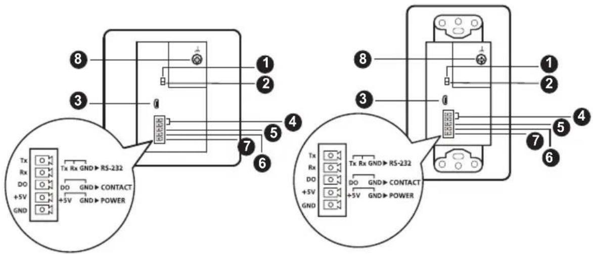
text_image
Tx Rx GND→RS-232 DO DO GND→CONTACT +5V GND POWER Tx Rx GND→RS-232 DO DO GND→CONTACT +5V GND POWER| No. | Component Description | |
| 1 | RS-232 for bypass channel switch | Put the switch to ON to bypass RS-232 serial data for remote control on the device connected to the VE1901AEUT / VE1901AUST using serial commands. |
| 2 | RS-232 for firmware upgrade switch | This switch is reserved for ATEN Technical Support. If you would like to do a firmware upgrade yourself, please contact your dealer. |
| 3 | firmware upgrade port | This port is reserved for ATEN Technical Support. If you would like to do a firmware upgrade yourself, please contact your dealer. |
| 4 RS-232 terminal (Tx & Rx) Connects to the 5-pin terminal block for the following purposes. | ||
| 5 DO contact closure terminal (DO for share pushbutton) | For remotely control on the connected device via RS-232 serial commands, connect the RS-232 main controller, such as a PC or a control system. See RS-232 Channel Transmission, page 15. | |
| 6 +5V DC power-in terminal (+5V) | For source sharing with the VP1421, connect the 5-pin terminal block to the DO contact closure terminal and the VP1421. See Connecting the Unit with VP1421, page 18. | |
| 7 ground terminal (GND) | For power redundancy, connect the 5-pin terminal block to the +5V DC power-in terminal. See Power Supply Information, page 14. | |
| For RS-232, DO contact closure, and +5V DC power-in terminals to work, connect the ground terminal (GND) to a ground wire. See Terminal Block Connection, page 13. | ||
| 8 grounding terminal Grounds the VE1901AEUT / VE1901AUST to prevent damages from power surge or static electricity. | ||
Top View
VE1901AEUT VE1901AUST

natural_image
Pure electrical circuit lines without any symbols
natural_image
Simple line drawing of a device with a labeled component (no text or symbols)| No. | Component Description | |
| 1 | HDBaseT out port with PoH PD power receiving | Connects to the HDBaseT input port on a compatible ATEN HDBaseT receiver via an RJ-45 cable. |
This Page Intentionally Left Blank
Chapter 2
Hardware Setup

-
Please review the safety information regarding the placement of this device in Safety Instructions, page 19.
-
Do not power on the VE1901AEUT / VE1901AUST until all the necessary hardware is connected.
Mounting the VE1901AEUT / VE1901AUST Unit
VE1901AEUT / VE1901AUST is designed to be installed in a wall, ground, or a table.
Site Preparation
Choose a location where cables are free of interference and install the cables into the wall before installing the unit.
The unit can be installed into a wall box or simply into a recession in the wall. Please reserve enough space in the site for the body of the unit.
For more information on the recommended reserved space for each unit, see page 24.
Drawing Screw Site
Screw sites are required to secure the unit into the wall. There are regional template screw sites and the unit can use the sites easily.
If you wish to create your own installation sites, the dimensions below will help you decide how to draw them.
Template is available at the end of the document for both models, please refer to Template Printing on page 33 for more details.
VE1901AEUT Wall Mount
- Secure the faceplate to the unit using the 4 PF screws provided.

natural_image
Technical line drawing of an electronic device showing internal components and mounting points (no text or symbols)- Secure the unit to the installation site using the 2 pan head screws provided, and attach the rubber pads onto the pan head screws. This installation site can be a wall, ground, or table.

text_image
wallVE1901AUST Wall Mount
- Secure the unit to a wall box or mud ring using the flat head screws provided.
Note: The wall box and mud ring are not provided in the package.
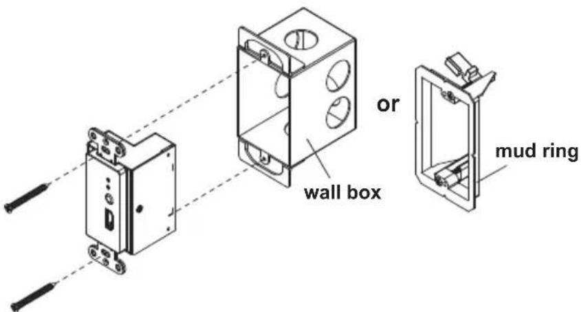
text_image
or wall box mud ring- Cover the unit by attaching the faceplate to it. Push-in the upper part and the lower part of the faceplate until it clicks in place. No screws are needed. This installation site can be a wall or ceiling.

natural_image
Diagram showing two devices connected by a dashed line, one with internal components and the other with a control panel (no text or symbols)Connecting the VE1901AEUT / VE1901AUST Unit
Follow the steps below to connect the VE1901AEUT / VE1901AUST to a source, a compatible ATEN HDBaseT receiver, and other controls as required.

flowchart
graph LR
    A["VE1901AUST Front View"] --> B["DP"]
    B --> C["2"]
    C --> D["Rear View"]
    D --> E["RS-232"]
    E --> F["5"]
    F --> G["6"]
    G --> H["Top View"]
    H --> I["DP"]
    I --> J["4"]
    J --> K["VE901R rear view (recommended)"]
    H --> L["Cat 5e/8/6a"]
    L --> M["3"]
    M --> N["VE901R front view (recommended)"]
    H --> O["Power"]
    O --> P["7"]

flowchart
graph LR
    A["VE1901AEUT Front View"] --> B["DP"]
    B --> C["2"]
    C --> D["Rear View"]
    D --> E["RS-232"]
    E --> F["5"]
    F --> G["6"]
    G --> H["Top View"]
    H --> I["DP"]
    I --> J["4"]
    J --> K["VE901R rear view (recommended)"]
    K --> L["Cat 5c/6/6a"]
    L --> M["3"]
    M --> N["VE901R front view (recommended)"]
    N --> O["Power"]
    O --> P["7"]
- Ground the unit by connecting one end of a grounding wire to a suitable grounded object.
Note: Do not omit this step. Proper grounding helps prevent damage to the unit from power surges or static electricity.
-
Connect the DisplayPort input port of the unit to the DisplayPort output port on your video source device using a DisplayPort cable.
-
Connect the unit to power by doing one, or both of the following for power redundancy:
- Connect one end of a Cat 5e/6/6a cable to the HDBaseT out port with PoH PD power receiving on the transmitter, and then connect the other end to the HDBaseT input port on a PoH PSE supported receiver (e.g., VP1421).
Note: If the connected receiver is not PoH PSE supported (e.g., VE901R), follow step 6.
- Connect the 5-pin terminal block to the +5V DC power-in and ground terminals on the unit (refer to step 6).
- Connect the DisplayPort output port on the VE901R to a display device using a DisplayPort cable.
- (Optional) Connect the RS-232 interface of your computer or control system to the RS-232 and ground terminals on the unit using the 5-pin terminal block provided.
- (Optional) Please follow the instructions described in Power Supply Information on page 13. Then plug the 5-pin terminal block into the +5V DC power-in and ground terminals on the unit to power on the device.
- Plug the power adapter cable into the power jack on the VE901R.
- Power on all connected devices.
Terminal Block Connection
Follow the instructions below for terminal block connection:
- Detach the terminal block from the port (e.g. RS-232 serial port).
- Loosen the screws on top of the terminal block (turning a screwdriver counter-clockwise) to open the gates.
- Insert the wires into the gates according to the label on the unit.
- Tighten the screws for each gate to secure the wires to the terminal block.
- Attach the terminal block back to its port.
Power Supply Information
(Optional) If you wish to use power adapter for power, follow the steps below.

text_image
1 +5V GND 5mm + - 2 3 +5V GND (+) (-)- Cut the connector end of the power adapter.
- Strip 5 mm (0.5cm) off the insulation cover of the power adapter cable to expose two wires: a +5V wire and a GND (grounding) wire.
- Insert the exposed +5V wire and GND (grounding) wire tightly into the 5-pin terminal block provided, which can be connected to the unit for power supply. Refer to Terminal Block Connection on page 13 for more details.
Note: One method to determine an exposed wire's polarity (i.e., +5V or GND) is by using a voltmeter.
RS-232 Channel Transmission
You can manage the connected devices via RS-232 serial devices, such as computers or bar code scanners. The RS-232 signal transmission flow can be illustrated as follows:
Note: The unit used in the diagram below is VE1901AUST, the procedure for connecting VE1901AEUT is identical.

flowchart
graph TD
    A["Server"] --> B["Client"]
    B --> C["Serial Device"]
    C --> D["Device 1"]
    C --> E["Device 2"]
    D --> F["Tx Rx Gnd"]
    E --> G["Tx Rx Gnd"]
    F --> H["Pin Configuration (Captive screw connectors)"]
    G --> I["Pin Configuration (Captive screw connectors)"]
    style A fill:#f9f,stroke:#333
    style B fill:#ccf,stroke:#333
    style C fill:#cfc,stroke:#333
    style D fill:#fcc,stroke:#333
    style E fill:#cff,stroke:#333
    style F fill:#ffc,stroke:#333
    style G fill:#ffc,stroke:#333
    style H fill:#fff,stroke:#333
    style I fill:#fff,stroke:#333
The general concept here is that a RS-232 signal can be transmitted (Tx) to the receiving (Rx) end of a unit. The received signal can then be transmitted (Tx) to the receiving (Rx) end of another unit. The RS-232 signals can be transmitted back the other way.
This Page Intentionally Left Blank
Chapter 3
Operation
RS-232 Serial Transmission
The RS-232 Serial Transmission allows you to bypass serial data to remotely control the device connected to the VE1901AEUT / VE1901AUST using serial commands.
Bypass
RS-232 serial data is bypassed from the controller PC or Pad to other connected devices. Remember to set the RS-232 for bypass channel switch to ON.
VE1901AEUT VE1901AUST
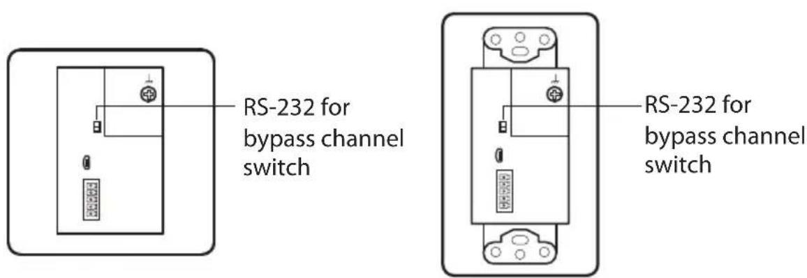
text_image
RS-232 for bypass channel switch RS-232 for bypass channel switchConnecting the Unit with VP1421
To share source device to the VP1421, follow the steps below. For more information on how to connect the VP1421, see VP1421-VP1421 user manual.
Note: The unit used in the diagram below is VE1901AUST, the procedure for connecting VE1901AEUT is identical.
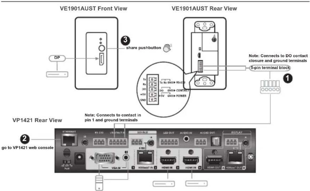
text_image
VE1901AUST Front View VE1901AUST Rear View DP share pushbutton Tx Rx GND RS-2D DO GND CONTACT +5V +5V GND POWER Note: Connects to DO contact closure and ground terminals 5-pin terminal block ① ② VP1421 Rear View Note: Connects to contact in pin 1 and ground terminals ② go to VP1421 web console ③ ④ ⑤ ⑥ ⑦ ⑧ ⑨ ⑩ ⑪ ⑫ ⑬ ⑭ ⑮ ⑯ ⑰ ⑱ ⑲ ⑳ ⑴ ⑵ ⑶ ⑷ ⑧ ⑨ ⑩ ⑪ ⑫ ⑬ ⑭ ⑮ ⑯ ⑰ ⑱ ⑲ ⑳ ⑪ ⑫ ⑬ ⑭ ⑮ ⑯ ⑰ ⑱ ⑲- Connect the DO contact closure and ground terminals to the contact in and ground terminals on the VP1421.
- Go to VP1421's web console. From the General page, use the drop-down menu to select Display A or Display B for the Target of Contact Closure (DI).
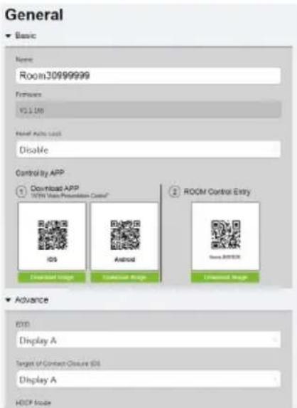
text_image
General Basic Name: Room30999999 Features: VCL100 Final Active User Disable Control by APP 1 Download APP 100% User Presentation Control iOS Android Windows Control Entry Windows Download Image Universal Image Download Image 2 ROOM Control Entry Advance EXO Display A Target of Contact Closure (OS) Display A HOSP Mode- Press the share button to remotely play the HDBaseT input source on VP1421's Display A or Display B depending on your Target of Contact Closure settings from step 2.
Safety Instructions
General
- This product is for indoor use only.
- Read all of these instructions. Save them for future reference.
◆ Follow all warnings and instructions marked on the device. - Do not place the device on any unstable surface (cart, stand, table, etc.). If the device falls, serious damage will result.
- Do not use the device near water.
- Do not place the device near, or over, radiators or heat registers.
- The device cabinet is provided with slots and openings to allow for adequate ventilation. To ensure reliable operation, and to protect against overheating, these openings must never be blocked or covered.
- The device should never be placed on a soft surface (bed, sofa, rug, etc.) as this will block its ventilation openings. Likewise, the device should not be placed in a built-in enclosure unless adequate ventilation has been provided.
- Never spill liquid of any kind on the device.
- Unplug the device from the wall outlet before cleaning. Do not use liquid or aerosol cleaners. Use a damp cloth for cleaning.
- The device should be operated from the type of power source indicated on the marking label. If you are not sure of the type of power available, consult your dealer or local power company.
- To prevent damage to your installation it is important that all devices are properly grounded.
- Do not allow anything to rest on the power cord or cables. Route the power cord and cables so that they cannot be stepped on or tripped over.
- Position system cables and power cables carefully; Be sure that nothing rests on any cables.
- Never push objects of any kind into or through cabinet slots. They may touch dangerous voltage points or short out parts resulting in a risk of fire or electrical shock.
- Do not attempt to service the device yourself. Refer all servicing to qualified service personnel.
- If the following conditions occur, unplug the device from the wall outlet and bring it to qualified service personnel for repair.
- The power cord or plug has become damaged or frayed.
♦ Liquid has been spilled into the device. - The device has been exposed to rain or water.
- The device has been dropped, or the cabinet has been damaged.
- The device exhibits a distinct change in performance, indicating a need for service.
- The device does not operate normally when the operating instructions are followed.
- Only adjust those controls that are covered in the operating instructions. Improper adjustment of other controls may result in damage that will require extensive work by a qualified technician to repair.
Technical Support
International
- For online technical support – including troubleshooting, documentation, and software updates: http://support.aten.com
◆ For telephone support, see Telephone Support, page vii:
North America
| Email Support support@aten-usa.com | ||
| Online Technical Support | Troubleshooting Documentation Software Updates | http://www.aten-usa.com/support |
| Telephone Support 1-888-999-ATEN ext 4988 | 1-949-428-1111 | |
When you contact us, please have the following information ready beforehand:
◆ Product model number, serial number, and date of purchase
- Your computer configuration, including operating system, revision level, expansion cards, and software
◆ Any error messages displayed at the time the error occurred
◆ The sequence of operations that led up to the error
◆ Any other information you feel may be of help
Specifications
| Function VE1901 | AEUT VE1901AUST | ||
| Video Input | |||
| Interfaces 1 x DisplayPort Female (Black) | |||
| Impedance DisplayPort: 100 Ω | |||
| Max. Distance 3 m | |||
| Video | |||
| Max. Data Rate 10.2 Gbps (3.4 Gbps per lane) | |||
| Max. Pixel Clock 297 MHz | |||
| Compliance DisplayPort (Deep Color, 4K) | |||
| Max. Resolutions / Distances | DisplayPort:◆ Up to 4k @35m (Cat 5e/6) / 40m (Cat 6a/ATEN 2L-2910 Cat6)◆ Up to 1080p @60m (Cat 5e/6) / 70m (Cat 6a/ATEN 2L-2910 Cat6)4k supported:◆ 4096 x 2160 / 3840 x 2160 @30Hz (4:4:4) | ||
| Audio | |||
| Input 1 x DisplayPort Female (Black) | |||
| Control | |||
| RS-232 Connectors 1 x Terminal Block, 5 Pole, TX / RX / GND (Green) | |||
| Contact Out | 1 x Terminal Block, 5 Pole, DO / GND (Green) | ||
| Switches | |||
| Bypass Channel | 1 Slide Switch - ON/OFF | ||
| Firmware Upgrade | 1 Slide Switch - ON/OFF | ||
| Power | |||
| Unit to Unit | 1 x RJ-45 Female | ||
| Connectors | 1 x Terminal Block, 5 Pole, +5V / GND (Green)1 x RJ-45 Female (PoH) | ||
| Consumption | DC 5V;2.97W;14BTUDC 48V;3.71W;17BTU | ||
| Function VE1901 | AEUT VE1901AUST | |
| Environmental | ||
| Operating Temperature 0 | -40°C | |
| Storage Temperature -20 | -60°C | |
| Humidity 0 x 80% RH, Non-Condensing | ||
| Physical Properties | ||
| Housing Metal | ||
| Weight 0.20kg (0.44 lb) | 0.21kg (0.46 lb) | |
| Dimensions (L x W x H) | 6.86 x 4.44 x 5.00 cm(2.7 x 1.75 x 1.97 in) | 10.41 x 4.44 x 5.00 cm(4.1 x 1.75 x 1.97 in) |
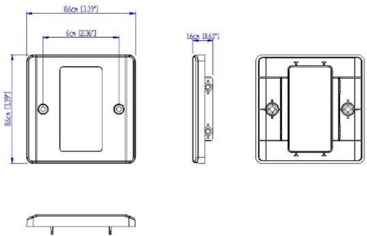
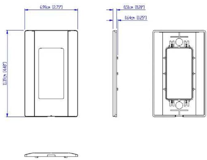
| Faceplate Dimensions(L x W x H) | 8.60 x 8.60 x 1.60 cm(3.39 x 3.39 x 0.63 in) | 11.39 x 6.99 x 0.64 cm(4.48 x 2.75 x 0.25 in) |
CAD Drawings
ATEN
VE1901AEUT

ATEN
VE1901AEUT

ATEN
VE1901AEUT
Panel Mount Cutout

text_image
Width of faceplate = 8.6 cm [3.39"] Height of faceplate = 8.6 cm [3.39"] 5.2 cm [2.05"] 7.2 cm [2.83"] Cutout AreaNote: ATEN recommends a 1-gang wall box with a depth of at least 5.5 cm (2.17 inches) to accommodate the connectors and cables.
ATEN
VE1801AEUT
VE1901AEUT
CAD Drawings
ATEN
VE1901AUST

ATEN
VE1901AUST

ATEN
VE1901AUST
Panel Mount Cutout
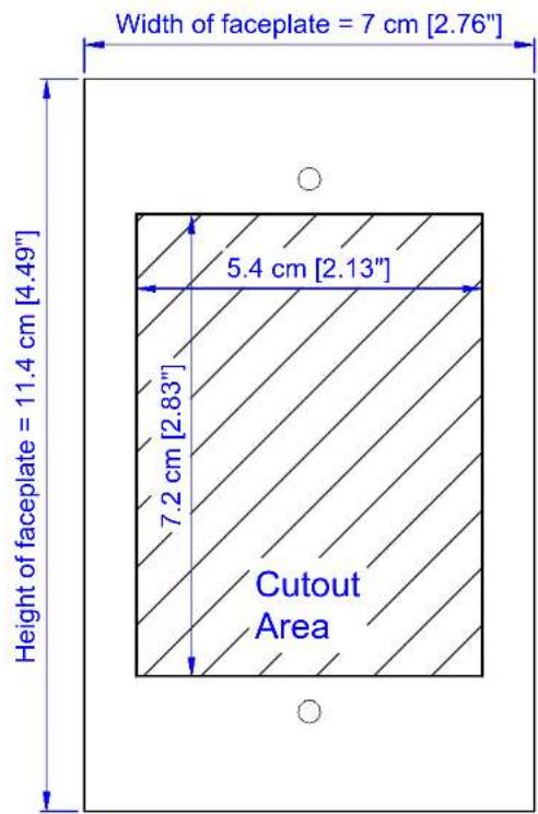
text_image
Width of faceplate = 7 cm [2.76"] Height of faceplate = 11.4 cm [4.49"] 5.4 cm [2.13"] 7.2 cm [2.83"] Cutout AreaNote: ATEN recommends a 1-gang wall box with a depth of at least 6 cm (2.36 inches) to accommodate the connectors and cables.
ATEN
VE1801AUST
VE1901AUST
Limited Warranty
ATEN warrants its hardware in the country of purchase against flaws in materials and workmanship for a Warranty Period of two [2] years (warranty period may vary in certain regions/countries) commencing on the date of original purchase. This warranty period includes the LCD panel of ATEN LCD KVM switches. Select products are warranted for an additional year (see A+ Warranty for further details). Cables and accessories are not covered by the Standard Warranty.
What is covered by the Limited Hardware Warranty
ATEN will provide a repair service, without charge, during the Warranty Period. If a product is detective, ATEN will, at its discretion, have the option to (1) repair said product with new or repaired components, or (2) replace the entire product with an identical product or with a similar product which fulfills the same function as the defective product. Replaced products assume the warranty of the original product for the remaining period or a period of 90 days, whichever is longer. When the products or components are replaced, the replacing articles shall become customer property and the replaced articles shall become the property of ATEN.
To learn more about our warranty policies, please visit our website: http://www.aten.com/global/en/legal/policies/warranty-policy/
© Copyright 2021 ATEN® International Co., Ltd.
Released: 2021-06-09
ATEN and the ATEN logo are registered trademarks of ATEN International Co., Ltd. All rights reserved. All other brand names and trademarks are the registered property of their respective owners.
Template Printing
Please use 1:1 ratios when printing.
We also recommend using A4 sized paper or larger.
After printing, please measure the print so that the labeled measurement is correct.

text_image
6cm Ø0.4cm