
VE2812PR - AV Switch ATEN - Free user manual and instructions
Find the device manual for free VE2812PR ATEN in PDF.


| Brand | ATEN |
| Model | VE2812PR |
| Product Type | AV Switch / HDMI Switch |
| Number of Inputs | 2 |
| Number of Outputs | 1 |
| Supported Resolution | 4K@60Hz (4:4:4), 1080p@120Hz |
| HDCP Version | 2.2 |
| Audio Formats | LPCM 2.0/5.1/7.1, Dolby TrueHD, DTS-HD Master Audio |
| HDR Support | HDR10, Dolby Vision |
| HDMI Standard | HDMI 2.0 |
| Power Supply | External 5V DC adapter |
| Power Consumption | 2.5W (max) |
| Dimensions (W x D x H) | 120 mm x 70 mm x 25 mm |
| Weight | 200 g |
| Enclosure Material | Metal |
| Control Method | Push button, IR remote (included) |
| LED Indicators | Power, Input selection |
| Package Contents | Switch, power adapter, IR remote, user manual |
| Maintenance & Cleaning | Clean with a soft, dry cloth. Do not use liquids or solvents. |
| Safety Instructions | Use only the supplied power adapter. Keep away from moisture and heat sources. |
| Spare Parts & Repairability | No user-serviceable parts. Contact ATEN support for repairs. |
| Compliance | CE, FCC, RoHS |
Frequently Asked Questions - VE2812PR ATEN
User questions about VE2812PR ATEN
0 question about this device. Answer the ones you know or ask your own.
Ask a new question about this device
Download the instructions for your AV Switch in PDF format for free! Find your manual VE2812PR - ATEN and take your electronic device back in hand. On this page are published all the documents necessary for the use of your device. VE2812PR by ATEN.
USER MANUAL VE2812PR ATEN
Simply Better Connections
VE2812R-VE2812PR
HDMI HDBaseT Receiver withAudio De-Embedding / Bi-directional PoH User Manual
Compliance Statements
FEDERAL COMMUNICATIONS COMMISSION INTERFERENCE STATEMENT
This equipment has been tested and found to comply with the limits for a Class A digital device, pursuant to Part 15 of the FCC Rules. These limits are designed to provide reasonable protection against harmful interference when the equipment is operated in a commercial environment. This equipment generates, uses, and can radiate radio frequency energy and, if not installed and used in accordance with the instruction manual, may cause harmful interference to radio communications. Operation of this equipment in a residential area is likely to cause harmful interference in which case the user will be required to correct the interference at his own expense.
The device complies with Part 15 of the FCC Rules. Operation is subject to the following two conditions: (1) this device may not cause harmful interference, and (2) this device must accept any interference received, including interference that may cause undesired operation.
FCC Caution
Any changes or modifications not expressly approved by the party responsible for compliance could void the user's authority to operate this equipment.
Warning
Operation of this equipment in a residential environment could cause radio interference.
Achtung
Industry Canada Statement
This Class A digital apparatus complies with Canadian ICES-003.
CAN ICES-003 (A) / NMB-003 (A)
HDMI Trademark Statement
The terms HDMI, HDMI High-Definition Multimedia Interface, and the HDMI Logo are trademarks or registered trademarks of HDMI Licensing Administrator, Inc.
HDMI
RoHS
This product is RoHS compliant.
VE2812R / VE2812PR User Manual
User Information
Online Registration
Be sure to register your product at our online support center:
International http://eservice.aten.com
Telephone Support
For telephone support, call this number:
International 886-2-8692-8959
China 86-400-810-0-810
Japan 81-3-5615-5811
Korea 82-2-467-6789
North America 1-888-999-ATEN ext 4988
1-949-428-1111
User Notice
All information, documentation, and specifications contained in this manual are subject to change without prior notification by the manufacturer. The manufacturer makes no representations or warranties, either expressed or implied, with respect to the contents hereof and specifically disclaims any warranties as to merchantability or fitness for any particular purpose. Any of the manufacturer's software described in this manual is sold or licensed as is. Should the programs prove defective following their purchase, the buyer (and not the manufacturer, its distributor, or its dealer), assumes the entire cost of all necessary servicing, repair and any incidental or consequential damages resulting from any defect in the software.
The manufacturer of this system is not responsible for any radio and/or TV interference caused by unauthorized modifications to this device. It is the responsibility of the user to correct such interference.
The manufacturer is not responsible for any damage incurred in the operation of this system if the correct operational voltage setting was not selected prior to operation. PLEASE VERIFY THAT THE VOLTAGE SETTING IS CORRECT BEFORE USE
VE2812R / VE2812PR User Manual
Product Information
For information about all ATEN products and how they can help you connect
without limits, visit ATEN on the Web or contact an ATEN Authorized
Reseller. Visit ATEN on the Web for a list of locations and telephone numbers:
International http://www.aten.com
North America http://www.alen-usa.com
Package Contents
Check to make sure that all the components are in working order. If you encounter any problem, please contact your dealer.
VE2812R
1 VE2812R HDMI HDBaseT Receiver with Audio De-Embedding
1 RS-232 terminal block
4 foot pads
1 power adapter
1 user instructions
VE2812PR
1 VE2812PR HDMI HDBaseT Receiver with Audio De-Embedding / Bidirectional PoH
1 RS-232 terminal block
1 foot pad set (4 pcs)
1 power adapter
1 user instructions
VE2812R / VE2812PR User Manual
Table of Contents
Compliance Statements ...... ii
User Information ....iv
Telephone Support....iv
User Notice iv
Product Information v
Package Contents ...... vi
Table of Contents VI
About this Manual . . . . . . . . . . . . . . . . . . . . . . . . . . . . . . . . . . . . . . . . . . . . . . . . . . . . . . . . . . . . . . . . . . . . . . .
Conventions ......x
1. Introduction
Overview....1
Features 2
Planning the Installation 3
Requirements 3
Considerations 3
Compatible Products....3
Components 4
VE2812R Front View. 4
VE2812R Rear View....5
VE2812PR Front View 6
VE2812PR Rear View 7
VE2812R LED Display 8
VE2812PR LED Display 9
2. Hardware Setup
Mounting the VE2812R Unit 11
Wall Mounting 11
Rack Mounting 1
Connecting the VE2812R Unit 12
Connecting the VE2812PR Unit 14
RS-232 Channel Transmission....16
3. Operation
RS-232 Serial Transmission....17
Bypass 17
Command 17
Command to Control VF2812R / VF2812PR 18
VE2812R / VE2812PR User Manual
Appendix
Safety Instructions....21
Rack Mounting 23
Technical Support 24
International 24
North America 24
Specifications 25
VE2812R....25
Limited Warranty 29
About this Manual
This user manual is provided to help you get the most from the VE2812R / VF2812PR unit. It covers all aspects of installation, configuration, and operation. An overview of the information found in the manual is provided below.
Chapter 1, Introduction introduces you to the VE2812R / VE2812PR. Its purpose, features, installation considerations, and panel components are presented and described.
Chapter 2, Hardware Setup describes the steps that are necessary to quickly and safely set up your installation.
Chapter 3, Operation explains the limitations, and how to adjust audio channel using the a switch and RS-232 commands.
Appendix provides a list of safety instructions and precautions, contact information for ATEN technical support, product specifications, and other technical information.
Note:
- Read this manual thoroughly and follow the installation and operation procedures carefully to prevent any damage to the unit or any connected devices.
- The product may be updated, with features and functions added, improved or removed since the release of this manual. For an up-to-date user manual, visit http://www.aten.com/global/en/
Conventions
This manual uses the following conventions:
Mono spaced indicates text that you should key in.
[] indicates keys you should press. For example, [Enter] means to press the Enter key. If keys need to be chorded, they appear together in the same bracket with a plus sign between them: [Ctrl+Alt].
- Numbered lists represent procedures with sequential steps.
◆ Bullet lists provide information, but do not involve sequential steps.
Indicates selecting the option (on a menu or dialog box, for example), that comes next. For example, Start > Run means to open the Start menu, and then select Run.
Indicates critical information.
Chapter 1 Introduction
Overview
Featuring powerful Class A HDBaseT technology, the VE2812R / VE2812PR is a receiver for 4K HDMI video, audio, and control signals over a distance of up to 100 m via a Cat 5c / 6 / 6a or ATEN 2L-2910 Cat 6 cable. HDMI signal transmission extends further up to 150 m @ 1080p when the HDBaseT Long Reach Mode is enabled.
Designed to optimize flexibility, the VE2812PR ships with 2-way PoH capability, either allowing a PoH PD-enabled Tx (VE2812AT series is recommended) to be remotely powered by the locally powered VE2812PR, or enabling power distribution along the cable from a PoH PSE-enabled Tx (VE1812T is recommended) to the VE2812PR.
Speaking of VE2812R / VE2812PR's audio dc-embedding, audio signal can be extracted from the incoming HDMI source and then transmitted through Coaxial or Stereo output to external audio distribution systems. The VE2812R / VE2812PR gives users the extra convenience when it comes to extending control and communication signals via the built-in RS-232 and bi-directional IR ports. Plus, it is HDCP 2.2 compliant and supports HDMI specification features, such as 4K2K, 3D, Deep Color, and CEC for reliable transmission of high-quality uncompressed HDMI content.
With all highlights packed in a compact enclosure, the VE2812R / VE2812PR assures easy and discreet installation, keeping the presentation space tidy. It is ideal for small / mid-sized areas where 4K HDMI and control signal transmission over a long distance is required, such as boardrooms, lecture halls, and digital signage applications.
Features
• Transmits 4K HDMI up to 100 m / 330 ft via Cat 5c / 6 / 6a or ATEN 2L-2910 Cat 6 cable
- Transmits HDMI up to 150 m / 492 ft @ 1080p in HDBaseT Long Reach Mode
• Bi-direction PoH*:
- Allows a PoH PD-enabled Tx to be remotely powered by the locally powered VE2812PR
- Enables power distribution from a PoH PSE-enabled Tx to the VE2812PR over the cable
- Audio de-embedding — extracts audio stream from the HDMI source and delivers as a separate audio from HDMI to Coaxial S/PDIF, or Stereo audio output
• Supports Audio EDID Switching (2ch Stereo, 5.1ch Surround sound, and AUTO)
- RS-232 serial communication switch — switch between command mode and bypass mode for various application requirements
• Supports bi-directional IR signal transmission (IR transmission is processed one direction at a time)
• HDMI (3D, Deep Color, 4K); HDCP 2.2 compliant
- Firmware upgradable
• Built-in 8KV / 15KV ESD protection
- Plug-and-play
• Rack-mountable using the VE-RMK1U
Note: The bi-directional PoH capability is only supported on VE2812PR.
Planning the Installation
Requirements
Prepare the following before installing the VE2812R / VE2812PR unit:
- 1 HDMI display device
♦ 1 Cat 5c/6/6a or ATEN 2L-2910 Cat 6 cable
Considerations
• To ensure video quality, use a Cat 5e/6/6a cable.
| Note: For best results, ATEN recommends using the ATEN 2L-2910 Cat 6 cable. |
- The maximum transmission distance varies at different parts of the transmission:
| Connection Interface Max. Distance | ||
| The VE2812R / VE2812PR to a compatible ATEN Video Extender Transmitter | Cat 5e/6/6a 100 m / 150 m(up to 1080p in Long Reach Mode) | |
| The VE2812R / VE2812PR to a display | HDMI 3 m | |
Compatible Products
The VE2812R / VE2812PR is designed to work with VE2812AT / VE2812AUST / VE2812AEUT / VE3912T, and also compatible with a wide range of ATEN video splitters, video switches, video extender transmitters, and video converters. Visit our official web site for more details.
Components
VE2812R Front View
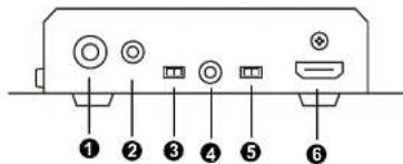
No. Component Description
| 1 audio out (coaxial) | Connects to the audio in (coaxial) port on a speaker. |
| 2 audio out (stereo) | Connects to the audio in (stereo) port on a speaker. |
| 3 audio channel switch | Use the switch to set the audio channel to 2.1 ch, 5.1 ch, or auto. |
| 4 IR port Connects to an IR emitter / receiver. | |
| 5 HDMI audio out switch | To mute the audio on the connected HDMI display, put the HDMI audio out switch to OFF. |
| 6 HDMI video out Connects to the HDMI in port on the display device. | |
VE2812R / VE2812PR User Manual
VE2812R Rear View
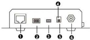
| No. | Component Description | |
| 1 | HDBaseT in Connects to the | HDBaseT output port on a compatible ATEN video transmitter via a Cat 5e / 6 / 6a / ATEN 2L-2910 cable. |
| 2 | RS-232 serial port Connects to an RS-232 main controller, such as a PC or Control system. | |
| 3 | RS-232 serial communication switch | Sets the RS-232 serial interface for signal Bypass or Command. For details, see page 17. |
| 4 | long reach mode switch | Put the switch to ON to enable the long reach mode. For more details on long reach mode, see page 20. |
| 5 | firmware upgrade switch This port is reserved for ATEN Technical Support. If you would like to do a firmware upgrade yourself, please contact your dealer. | |
| 6 | power jack Connects to the power adapter. | |
VE2812PR Front View

No. Component Description
| 1 audio out (coaxial) | Connects to the audio in (coaxial) port on a speaker. |
| 2 audio out (stereo) | Connects to the audio in (stereo) port on a speaker. |
| 3 audio channel switch | Use the switch to set the audio channel to 2.1 ch, 5.1 ch, or auto. |
| 4 IR port Connects to an IR emitter / receiver. | |
| 5 HDMI audio out switch | To mute the audio on the connected HDMI display, put the HDMI audio out switch to OFF. |
| 6 HDMI video out Connects to the HDMI in port on the display device. | |
VE2812R / VE2812PR User Manual
VE2812PR Rear View

| No. | Component Description | |
| 1 | HDBaseT in Connects to the | HDBaseT output port on a compatible ATEN video transmitter via a Cat 5e / 6 / 6a / ATEN 2L-2910 cable. |
| 2 | PoH PSE & PD switch Sets the unit between PSE and PD mode.◆ PSE: The unit receives power from the power adapter and delivers power to a PoH PD-supported device through its HDBaseT input port.◆ PD: The unit receives power from a PoH PSE-enabled Tx through its HDBaseT input port. | |
| 3 | RS-232 serial port Connects to an RS-232 main controller, such as a PC or Control system. | |
| 4 | RS-232 serial communication switch | Sets the RS-232 serial interface for signal Bypass or Command. For details, see page 17. |
| 5 | long reach mode switch | Put the switch to ON to enable the long reach mode. For more details on long reach mode, see page 20. |
| 6 | firmware upgrade switch This port is reserved for ATEN Technical Support. If you would like to do a firmware upgrade yourself, please contact your dealer. | |
| 7 | power jack Connects to the power adapter. | |
VE2812R LED Display
You can find the unit's LEDs on the top and front panel as illustrated below. See the table below for details on LED indication.
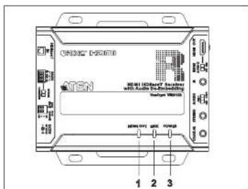
| No. | LED Indication Description | ||
| 1 | HDMI out status LED | Lights orange | Video display is normal with HDCP key. |
| Blinks orange | Video display is normal without HDCP key. | ||
| Off Video signal dropped. | |||
| 2 | link LED | Lights orange | The transmission from the transmitter to the receiver is stable. |
| Off The transmission from the transmitter to the receiver is unstable. | |||
| 3 | power LED Lights green | The unit is powered on. | |
| Off The unit is powered off. | |||
| Note:The power, link LED and HDMI out Status LEDs blink at the same time to indicate that the firmware upgrade is in progress. | |||
VE2812R / VE2812PR User Manual
VE2812PR LED Display
You can find the unit's LEDs on the top and front panel as illustrated below.
See the table below for details on LED indication.
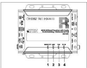
| No. | LED Indication Description | |
| 1 | HDMI out LED Lights | orange Video display is normal with HDCP key. |
| Blinks orange Video display is normal without HDCP key. | ||
| Off Video signal dropped. | ||
| 2 | link LED Lights orange | The transmission from the transmitter to the receiver is stable. |
| Off The transmission from the transmitter to the receiver is unstable. | ||
| 3 | PoH power LED Lights | green The unit is receiving power through PoH and powered on. |
| Off The unit is not receiving power through PoH. | ||
| 4 | DC-in power LED | Lights green The unit is receiving power from a power adapter and powered on. |
| Off The unit is not receiving power from a power adapter. |
Chapter 1. Introduction
| No. | LED Indication | Description | |
| Note:The DC-in power LED and link LEDs blink at the same time to indicate that the firmware upgrade is in progress.For power redundancy, connect the power jack to a power adapter and the HDBaseT input port to a PoH PSE-enabled Tx via a Cat 5e / 6 / 6a or ATEN 2L-2910 cable, and put the PoH PSE & PD switch to PD. Both the DC-in power and PoH power LEDs light green,to indicate that the power redundancy is in effect.When both the PoH power and DC-in power LEDs are off, the unit is powered off. | |||
Chapter 2
Hardware Setup

- Please review the safety information regarding the placement of this device in Safety Instructions, page 21.
- Do not power on the VE2812R / VE2812PR until all the necessary hardware is connected.
Mounting the VE2812R Unit
You can mount the VE2812R / VE2812PR to the wall or on a rack.
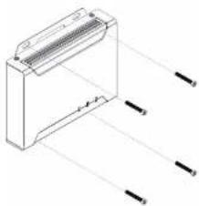
Wall Mounting
Secure or hang the VI:2812R / VI:2812PR unit to the wall using the built-in mounting brackets.
natural_image
Technical line drawing of a mechanical component with multiple pins (no text or symbols)Rack Mounting
Use the VE-RMK 1U Rack Mount Kit to rack-mount the VE2812R /
VE2012DD. For more information about this necessary, go to
Chapter 2. Hardware Setup
Connecting the VE2812R Unit
Follow the steps below to connect the VE2812R to an HDMI-enabled display source, a compatible ATEN Video Transmitter, and other controls as required.

flowchart
graph TD
    A["Speaker"] --> B["Rear"]
    C["IR Receiver"] --> D["Router"]
    E["Wireless"] --> F["HD/Inducts"]
    G["VR2812R (Front)"] --> H["Speaker"]
    I["VR2812R (Rear)"] --> J["HD/Inducts"]
    K["VR2812R (Front)"] --> L["Power"]
    M["VR2812R (Rear)"] --> N["Power Adapter"]
    O["VR2812R (Front)"] --> P["Power Adapter"]
    Q["VR2812R (Rear)"] --> R["Power Adapter"]
    S["VR2812R (Front)"] --> T["Power Adapter"]
    U["VR2812R (Rear)"] --> V["Power Adapter"]
    W["VR2812R (Front)"] --> X["Power Adapter"]
    Y["VR2812R (Rear)"] --> Z["Power Adapter"]
- Connect an HDMI-enabled display to the VE2812R's HDMI out port.
- Follow the steps below to set up your audio output.
a) To use an independent speaker, connect the speaker to the VE2812R's audio out port (coaxial or stereo) using an appropriate audio cable.
b) Depending on the interface of your chosen audio output device, adjust the audio signal using the audio channel switch.
| Audio Interface | Audio Channel Switch | Description |
| Stereo 2 ch | Sets the audio output to channel 2. | |
| Coaxial 5.1 | ch Sets the audio output to channel 5.1. | |
| HDMI Auto | Detects the supported audio channel of the connected HDMI display. | |
Note: Stereo audio will be muted if the channel is set to CH5.1.
c) To mute the audio on the connected HDMI display, put the HDMI audio
Note: ATEN recommends pairing the VE2812R with VE2812AT / VE2812AUST / VE2812AEUT / VE3912T.
- (Optional) To bypass IR signals to remotely control a device (e.g. blue-ray disc) connected to the video transmitter, connect an IR receiver to the VE2812R's IR port and an IR emitter to the VE2812AT / VE2812AUST / VE2812AEUT / VE3912T's IR port.
Note: To purchase an IR receiver and an IR remote control, contact your local sales representative for more information.
-
(Optional) You can use the RS-232 serial port to do one of the following:
-
To control the VE2812AT / VE2812AUST / VE2812AEUT / VE3912T using an ATEN Control System/Control Pad, connect a Control Box / Control Pad to the VE2812R's RS-232 serial port and then put the RS-232 serial communication switch to Command.
- To bypass RS-232 serial control signals to a PC or a serial device, connect the PC or serial device (e.g. touch pad) to the VE2812R's RS-232 serial port and put the RS-232 serial communication switch to Bypass.
- Ground the devices connected to the VE2812R to prevent damages from power surges or static electricity.
- Plug the power cord into the VE2812R's power jack.
Connecting the VE2812PR Unit
Follow the steps below to connect the VE2812PR to an HDMI-enabled display source, a compatible ATEN Video Transmitter, and other controls as required.

flowchart
graph TD
    A["VE2812PR (Front)"] --> B["Speakers"]
    A --> C["IR"]
    A --> D["Monitor"]
    B --> E["IR"]
    C --> F["IR"]
    D --> G["HDMIAudio"]
    H["VE2812AT (recommended)"] --> I["HDBase7"]
    I --> J["IR"]
    J --> K["IR emitter / receiver"]
    L["VE2812PR (Rear)"] --> M["R5-232"]
    M --> N["Power"]
    N --> O["VK Control System"]
    N --> P["PC"]
    N --> Q["Power Adapter"]
    style A fill:#f9f,stroke:#333
    style H fill:#f9f,stroke:#333
    style L fill:#f9f,stroke:#333
    style O fill:#ccf,stroke:#333
    style P fill:#ccf,stroke:#333
    style Q fill:#ccf,stroke:#333
- Before installation, please make sure the VE2812PR is set to PoH PSE or PoH PD mode using the DIP switch for your installation requirement.
- Set the PoH PSE & PD switch to PSE: The VE2812PR receives power from the power adapter and delivers power to a PoH PD-supported device through its HDBascT input port.
- Set the PoH PSE & PD switch to PD: The VE2812PR receives power from a PoH PSE-supported device through its HDBaseT input port.
- Use a grounding wire to ground the unit by connecting one end to the
Note: Do not omit this step. Proper grounding helps prevent damage to the unit from power surges or static electricity.
- Connect an HDMI-enabled display to the unit's HDMI output port.
- Follow the steps below to set up your audio output.
a) To use an independent speaker, connect the speaker to the unit's audio output port (coaxial or stereo) using an appropriate audio cable.
b) Depending on the interface of your chosen audio output device, adjust the audio channel switch if necessary.
| Audio Interface | Audio Channel Switch | Description |
| Stereo 2 ch | Sets the audio output to channel 2. | |
| Coaxial 5.1 ch | Sets the audio output to channel 5.1. | |
| HDMI Auto | Detects the supported audio channel of the connected HDMI display. | |
Note: The stereo audio will be muted if the channel is set to CH 5.1.
c) To mute the audio on the connected HDMI display, put the HDMI audio out switch of OFF.
- Connect a video transmitter's HDBaseT output port to the unit's HDBaseT input port using a Cat 6a / ATEN 2L-2910 cable.
Note: ATEN recommends pairing the VE2812PR with VE2812AT.
- (Optional) To bypass IR signals to remotely control a device (e.g., Blu-ray player) connected to the video transmitter, connect an IR receiver to the unit's IR port and an IR emitter to the VE2812AT's IR port.
Note: To purchase an IR receiver and an IR emitter, please contact your ATEN dealer for more information.
- (Optional) You can use the RS-232 serial port to do one of the following: a) To control the VE2812AT using an ATEN controller, connect the ATEN
Chapter 2. Hardware Setup
b) To bypass RS-232 serial control signals to a PC or a serial device, connect the PC or serial device (e.g., touch pad) to the unit's RS-232 serial port and put the RS-232 serial communication switch to Bypass.
- (Optional) Connect the power adapter to the unit's power jack or connect a PoH PSE-supported device to the unit's HDBaseT input port for power supply and operation.
RS-232 Channel Transmission
You can manage the VE2812R / VE2812PR via RS-232 serial devices, such as computers or bar code scanners. The RS-232 signal transmission flow can be illustrated as follows:

flowchart
graph TD
    A["Central Device"] --> B["Pin 1: 6.16s"]
    A --> C["Pin 2: 6.16s"]
    A --> D["Pin 3: 6.16s"]
    A --> E["Pin 4: 6.16s"]
    A --> F["Serial Device"]
    G["Pin 5: 6.16s"] --> H["Pin 6: Grid"]
    I["Pin 7: Grid"] --> J["Pin 8: Grid"]
    K["Pin 9: Grid"] --> L["Pin 10: Grid"]
    M["Pin 11: Grid"] --> N["Pin 12: Grid"]
From a source device, the RS-232 signal is transmitted (Tx) to the VE2812R / VE2812PR receiving (Rx) unit; the a compatible ATEN Video Receiver transmits (Tx) signals to the display device (Rx).
You can set the VE2812R / VE2812PR to either bypass serial data or to receive RS-232 commands. By default, the VE2812R / VE2812PR is set to bypass serial data. To set the unit to receive RS-232 commands, press the Input Switch pushbutton for 5 seconds. For details on RS-232 commands, see RS-232 Serial Transmission, page 17.
Chapter 3
Operation
RS-232 Serial Transmission
The RS-232 Serial Transmission allows you to choose whether to bypass serial data or to remotely control the VE2812AT / VE2812AUST / VE2812AEUT / VF3912T using commands depending on your installation.
You can simply switch RS-232 mode between Command / Bypass by clicking the RS-232 Serial Communication Switch listed below.
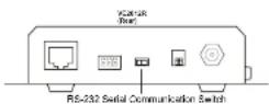
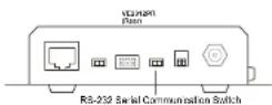
Note: By default, the VE2812R / VE2812PR is set to Bypass serial data.
Bypass
RE-232 serial data is bypassed from the controller PC or Pad to other connected devices.
Command
You can change the input mode on VE2812R / VE2812AT / VE2812AUST / VE2812AEUT / VE3912T using RS-232 commands.
Command to Control VE2812R / VE2812PR
To control VE2812R / VE2812PR please refer to the table below for a list of available tasks and the corresponding commands. For example, to mute the HDMI display sound, type mute HDMI audio on and then press [Enter].
| Task | Command |
| Control | |
| Mutos the HDMI display sound mute HDMI audio on | |
| Unmutes the HDMI display sound mute HDMI audio off | |
| Note:In order for the above two commands to work, the HDMI Audio Out Switch must be switched to OFF. | |
| Mutes the stereo and coaxial sound mute audio on | |
| Unmutes the stereo and coaxial sound mute audio off | |
| Note:Press [Enter] to execute a command. | |
| Reboots the unit reboot | |
| Views the current input mode settings read | |
VE2812R / VE2812PR User Manual
Command to Control VE2812AT / VE2812AUST / VE2812AEUT
You can change the input mode of VE2812AT / VE2812AUST /
VE2812AEUT using RS-232 commands. Refer to the table below for a list of available tasks and the corresponding commands. For example, to enable automatic switching, type swmode plugin auto and then press [Enter].
| Task | Command | |
| Control Input Port | ||
| Enables automatic input switching swmode plugin auto N/A N/A | ||
| Disables automatic input switching swmode plugin off N/A N/A | ||
| Enables automatic plug-out switching | swmode plugout prev N/A N/A | |
| Disables automatic plug-out switching | swmode plugout off N/A N/A | |
| Sets the unit to the HDMI mode sw i 01 | ||
| Sets the unit to the VGA mode sw i 02 | ||
| Note:Press [Enter] to execute a command. | ||
Command to Control VE3912T
You can change the input mode of VE3912T using RS-232 commands. Refer to the table below for a list of available tasks and the corresponding commands. For example, to enable automatic switching, type swmode plugin auto and then press [Enter].
| Task | Command | |
| Control Input Port | ||
| Enables automatic input switching swmode plugin auto N/A N/A | ||
| Disables automatic input switching swmode plugin off N/A N/A | ||
| Enables automatic plug-out switching | swmode plugout prev N/A N/A | |
| Disables automatic plug-out | swmode plugout off N/A N/A | |
Chapter 3. Operation
| Task | Command | ||
| Control Input Port | |||
| Sets the unit to the HDMI mode sw i 02 | |||
| Sets the unit to the VGA mode sw i 03 | |||
Note:
- Press [Enter] to execute a command.
Long Reach Mode
Long reach mode is a modulation that extends the transmission distance up to 150 m using a Cat 5e/6 cable while compromising the maximum frame rate to 1080p, 24 bpp, 60 Hz via a single Cat 5e/6 cable. To enable long reach mode, put the HDBaseT long reach mode switch to ON at either the transmitter or the connected receiver.


Note: When long reach mode is enabled, the VE2812R / VE2812PR will not be able to transmit 4K signals, in which case, the output display will be blank.
Appendix
Safety Instructions
General
• This product is for indoor use only.
- Read all of these instructions. Save them for future reference.
• Follow all warnings and instructions marked on the device.
- Do not place the device on any unstable surface (cart, stand, table, etc.). If the device falls, serious damage will result.
• Do not use the device near water.
- Do not place the device near, or over, radiators or heat registers.
- The device cabinet is provided with slots and openings to allow for adequate ventilation. To ensure reliable operation, and to protect against overheating, these openings must never be blocked or covered.
- The device should never be placed on a soft surface (bed, sofa, rug, etc.) as this will block its ventilation openings. Likewise, the device should not be placed in a built-in enclosure unless adequate ventilation has been provided.
• Never spill liquid of any kind on the device.
- Unplug the device from the wall outlet before cleaning. Do not use liquid or aerosol cleaners. Use a damp cloth for cleaning.
- The device should be operated from the type of power source indicated on the marking label. If you are not sure of the type of power available, consult your dealer or local power company.
• To prevent damage to your installation it is important that all devices are properly grounded.
- Do not allow anything to rest on the power cord or cables. Route the power cord and cables so that they cannot be stepped on or tripped over.
- Position system cables and power cables carefully; Be sure that nothing rests on any cables.
- Never push objects of any kind into or through cabinet slots. They may touch dangerous voltage points or short out parts resulting in a risk of fire
Appendix
- If the following conditions occur, unplug the device from the wall outlet and bring it to qualified service personnel for repair.
• The power cord or plug has become damaged or frayed.
• Liquid has been spilled into the device.
• The device has been exposed to rain or water.
- The device has been dropped, or the cabinet has been damaged.
- The device exhibits a distinct change in performance, indicating a need for service.
- The device does not operate normally when the operating instructions are followed.
- Only adjust those controls that are covered in the operating instructions. Improper adjustment of other controls may result in damage that will require extensive work by a qualified technician to repair.
Rack Mounting
Before working on the rack, make sure that the stabilizers are secured to the rack, extended to the floor, and that the full weight of the rack rests on the floor. Install front and side stabilizers on a single rack or front stabilizers for joined multiple racks before working on the rack.
- Always load the rack from the bottom up, and load the heaviest item in the rack first.
- Make sure that the rack is level and stable before extending a device from the rack.
- Use caution when pressing the device rail release latches and sliding a device into or out of a rack; the slide rails can pinch your fingers.
- After a device is inserted into the rack, carefully extend the rail into a locking position, and then slide the device into the rack.
- Do not overload the AC supply branch circuit that provides power to the rack. The total rack load should not exceed 80 percent of the branch circuit rating.
- Make sure that all equipment used on the rack – including power strips and other electrical connectors – is properly grounded.
- Ensure that proper airflow is provided to devices in the rack.
- Ensure that the operating ambient temperature of the rack environment does not exceed the maximum ambient temperature specified for the equipment by the manufacturer.
- Do not step on or stand on any device when servicing other devices in a rack.
Appendix
Technical Support
International
- For online technical support – including troubleshooting, documentation, and software updates: http://support.aten.com
• For telephone support, see Telephone Support, page iv:
North America
| Email Support support@aten-usa.com | ||
| Online Technical Support | TroubleshootingDocumentationSoftware Updates | http://www.aten-usa.com/support |
| Telephone Support 1-888-999-ATEN ext 4988 | ||
When you contact us, please have the following information ready beforehand:
• Product model number, serial number, and date of purchase
- Your computer configuration, including operating system, revision level, expansion cards, and software
• Any error messages displayed at the time the error occurred
• The sequence of operations that led up to the error
• Any other information you feel may be of help
VE2812R / VE2812PR User Manual
Specifications
VE2812R
| Function VE2812R | |
| Video Output | |
| Interfaces 1 x HDMI Type-A Female (Black) | |
| Impedance HDMI: 100 Ω | |
| Max. Distance 3 m | |
| Video | |
| Max. Data Rate 10.2 Gbps (3.4 Gbps per lane) | |
| Max. Pixel Clock 340 MHz | |
| Compliance HDMI (3D, Deep Color, 4K) | |
| Max. Resolutions 4K supported:4096 x 2160 / 3840 x 2160 @ 60 Hz (4:2:0):4096 x 2160 / 3840 x 2160 @ 30 Hz (4:4:4) | |
| Max. Resolutions /Distances | • Up to 4k @70m (Cat 5e/6) / 100m (Cat 6a/ATEN2L-2910 Cal6)• Up to 1080p @100m (Cat 5e/6/6a) |
| Audio | |
| Output 1 x HDMI Type-A Female (Black)1 x Mini Stereo Jack Female (Green)1 x SPDIF Coaxial Female (Orange) | |
| Connectors | |
| Unit To Unit 1 x RJ-45 Female | |
| Power 1 x DC Jack (Black) with locking | |
| Control | |
| RS-232 Connectors | 1 x Terminal Block, 3 Pole, Type: DTE |
| Baud Rate | 115200 bps |
Appendix
| Function VE281 2R | |
| Power Consumption | DC5V:4.98W:43BTU |
| Switches | |
| HDMI Mute 1 x Slide S | switch - HDMI Audio ON/OFF |
| Audio EDID Selection | x Slide Switch - Audio Output Format Selection: 2ch / 5.1ch/ AUTO |
| Mode Selection 1 x Slide | Switch - RS-232 Bypass or Command Mode Selection |
| Long Reach Mode Switch | 1 Slide Switch - Long Reach Mode ON/OFF |
| Firmware Upgrade 1 S | lide Switch - Firmware Upgrade Mode ON/OFF |
| Environmental | |
| Operating Temperature | 0 - 40°C |
| Storage Temperature | -20 - 60°C |
| Humidity 0 x 80% RH, | Non-Condensing |
| Physical Properties | |
| Housing Metal | |
| Weight 0.46 Kg (1.01 lb) | |
| Dimensions (L x W x H) with Bracket | 14.53 x 12.30 x 3.00 cm (5.72 x 4.84 x 1.18 in) |
| Dimensions (L x W x H) without Bracket 13.6 | 0 x 10.10 x 2.90 cm (5.35 x 3.98 x 1.14 in) |
VE2812R / VE2812PR User Manual
VE2812PR
| Function VE2812PR | |
| Video Output | |
| Interfaces 1 x HDMI Type-A Female (Black) | |
| Impedance HDMI: 100 Ω | |
| Max. Distance 3 m | |
| Video | |
| Max. Data Rate 10.2 Gbps (3.4 Gbps per lane) | |
| Max. Pixel Clock 340 MHz | |
| Compliance HDMI (3D, Deep Color, 4K) | |
| Max. Resolutions 4K supported:4096 x 2160 / 3840 x 2160 @ 60 Hz (4:2:0);4096 x 2160 / 3840 x 2160 @ 30 Hz (4:4:4) | |
| Max. Resolutions /Distances | • Up to 4k @70m (Cat 5e/6) / 100m (Cat 6a/ATEN2L-2910 Cat6)• Up to 1080p @100m (Cat 5e/6/6a) |
| Audio | |
| Output 1 x HDMI Type-A Female (Black)1 x Mini Stereo Jack Female (Green)1 x SPDIF Coaxial Female (Orange) | |
| Connectors | |
| Unit To Unit 1 x RJ-45 Female | |
| Power 1 x DC Jack (Black) with locking1 x RJ-45 Female, PoH PD & PSE supported | |
| Control | |
| RS-232 Connectors | 1 x Terminal Block, 3 Pole, Type: DTE |
| Baud Rate | 115200 bps |
| Data Bits | 8 |
| Stop Bits | 1 no parity and flow control |
Appendix
| Function VE281 2PR | |
| Switches | |
| Power Selected 1 x Slide | Switch - PoH Power Selection: PSE / PD |
| HDMI Mute 1 x Slide | Switch - HDMI Audio ON/OFF |
| Audio EDID Selection | x Slide Switch - Audio Output Format Selection: 2ch / 5.1ch/ AUTO |
| Mode Selection 1 x Slide | Switch - RS-232 Bypass or Command Mode Selection |
| Long Reach Mode Switch | 1 Slide Switch - Long Reach Mode ON/OFF |
| Firmware Upgrade 1 S | lide Switch - Firmware Upgrade Mode ON/OFF |
| Environmental | |
| Operating Temperature | 0 - 40°C |
| Storage Temperature | -20 - 60°C |
| Humidity 0 x 80% RH, | Non-Condensing |
| Physical Properties | |
| Housing Metal | |
| Weight 0.50 Kg (1.1 lb) | |
| Dimensions (L x W x H) with Bracket | 14.53 x 12.30 x 3.00 cm (5.72 x 4.84 x 1.18 in) |
| Dimensions (L x W x H) without Bracket 13.6 | 0 x 10.10 x 2.90 cm (5.35 x 3.98 x 1.14 in) |
VE2812R / VE2812PR User Manual
Limited Warranty
ATEN warrants its hardware in the country of purchase against flaws in materials and workmanship for a Warranty Period of two [2] years (warranty period may vary in certain regions/countries) commencing on the date of original purchase. This warranty period includes the LCD panel of ATEN LCD KVM switches. Select products are warranted for an additional year (see A-Warranty for further details). Cables and accessories are not covered by the Standard Warranty.
What is covered by the Limited Hardware Warranty
ATEN will provide a repair service, without charge, during the Warranty Period. If a product is detective, ATEN will, at its discretion, have the option to (1) repair said product with new or repaired components, or (2) replace the entire product with an identical product or with a similar product which fulfills the same function as the defective product. Replaced products assume the warranty of the original product for the remaining period or a period of 90 days, whichever is longer. When the products or components are replaced, the replacing articles shall become customer property and the replaced articles shall become the property of ATEN.
To learn more about our warranty policies, please visit our website: http://www.aten.com/global/en/legal/policies/warranty-policy/


- VE2812R-VE2812PR
- Compliance Statements
- FEDERAL COMMUNICATIONS COMMISSION INTERFERENCE STATEMENT
- FCC Caution
- Warning
- Achtung
- Industry Canada Statement
- CAN ICES-003 (A) / NMB-003 (A)
- HDMI Trademark Statement
- HDMI
- RoHS
- User Information
- Online Registration
- Telephone Support
- User Notice
- Product Information
- Package Contents
- VE2812R
- VE2812PR
- Table of Contents
- Introduction
- Hardware Setup
- Operation
- Appendix
- About this Manual
- Note:
- Conventions
- Chapter 1 Introduction
- Overview
- Features
- Planning the Installation
- Requirements
- Considerations
- Compatible Products
- Components
- VE2812R Front View
- VE2812R Rear View
- VE2812PR Front View
- VE2812PR Rear View
- VE2812R LED Display
- VE2812PR LED Display
- Chapter 2
- Hardware Setup
- Mounting the VE2812R Unit
- Wall Mounting
- Rack Mounting
- Connecting the VE2812R Unit
- Connecting the VE2812PR Unit
- Chapter 2. Hardware Setup
- RS-232 Channel Transmission
- Chapter 3
- Operation
- RS-232 Serial Transmission
- Bypass
- Command
- Command to Control VE2812R / VE2812PR
- Command to Control VE2812AT / VE2812AUST / VE2812AEUT
- Command to Control VE3912T
- Long Reach Mode
- Safety Instructions
- General
- Technical Support
- International
- Limited Warranty
- What is covered by the Limited Hardware Warranty
Brand : ATEN
Model : VE2812PR
Category : AV Switch