A-151v - Synthesizer Doepfer - Free user manual and instructions
Find the device manual for free A-151v Doepfer in PDF.

User questions about A-151v Doepfer
0 question about this device. Answer the ones you know or ask your own.
Ask a new question about this device
Download the instructions for your Synthesizer in PDF format for free! Find your manual A-151v - Doepfer and take your electronic device back in hand. On this page are published all the documents necessary for the use of your device. A-151v by Doepfer.
USER MANUAL A-151v Doepfer
flowchart
graph TD
    A["SYNC"] --> B["A-110 VCO"]
    C["CV 1"] --> B
    D["CV 2"] --> B
    E["PW CV 1"] --> B
    F["PW CV 2"] --> B
    B --> G["Range"]
    B --> H["Tune"]
    B --> I["PW"]
    B --> J["AC"]
    style A fill:#f9f,stroke:#333
    style C fill:#ccf,stroke:#333
    style D fill:#cfc,stroke:#333
    style E fill:#fcc,stroke:#333
    style F fill:#cff,stroke:#333
    style G fill:#ffc,stroke:#333
    style H fill:#cfc,stroke:#333
    style I fill:#fcc,stroke:#333
    style J fill:#ffc,stroke:#333
1. Introduction
Module A-110 (VCO) is a voltage-controlled oscillator.
This VCO's frequency range is about ten octaves. It can produce four waveforms simultaneously: square, sawtooth, triangle, and sine wave.
The Frequency or pitch of the VCO is determined by the position of the octave (Range) switch and tuning (Tune) knob, and by the voltage present at the CV inputs. Frequency modulation (FM) of the VCO is therefore a possibility. Footage (the octave of the fundamental) is set by the Range control, and Fine tuning controlled by the Tune knob.
You can control the pulse width of the square wave either by hand, or by voltage control - Pulse Width Modulation or PWM.
H
Because of the analog nature of the design, the VCO may need about 20 minutes' warm-up time for the tuning to become completely stable.
- VCO Overview
text_image
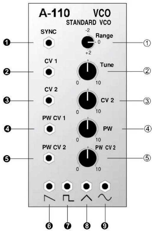
A-110 VCO STANDARD VCO SYNC -2 Range +2 0 CV 1 Tune 0 10 CV 2 CV 2 0 10 PW CV 1 PW 0 10 PW CV 2 PW CV 2 0 10 ① ① ② ② ③ ③ ④ ④ ⑤ ⑤ ⑥ ⑦ ⑧ ⑨Controls:
1 Range: 5-position Octave or Footage switch
2 Tune: Fine tuning control
3 CV 2: Attenuator for voltage at CV 2 (③)
4 PW: Manual control for Pulse Width
5 PW CV 2: Attenuator for PWM voltage at PW CV 2 (⑤)
In / outputs:
! SYNC: Sync input
" CV 1: Voltage control input 1
§ CV 2: Voltage control input 2, level adjustable with ③
\$ PW CV 1: PWM input 1
% PW CV 2: PWM input 2, level adjustable with ⑤
& :Sawtooth output
/ :Square wave output
( : Triangle wave output
) : Sine wave output
3. Basics
Module A-110 puts out four waveforms simultaneously. All these signals have the same pitch, since all are controlled by the same voltages present at inputs " and § .
Sawtooth
The VCO's sawtooth waveform is present at output &. It has a 'cutting' sound, rich in overtones. All the harmonics of the fundamental are present, with a linear reduction in intensity as the harmonic series progresses - so that the second harmonic is half as strong, the third is one third, the fourth a quarter, and so on (see Fig. 1).

bar
| Harmonics | Amplitude | | --------- | --------- | | f₁ | 100% | | f₂ | ~60% | | f₃ | ~45% | | f₄ | ~35% | | f₅ | ~30% | | f₆ | ~25% | | f₇ | ~20% | | f₈ | ~18% | | f₉ | ~15% |Fig. 1: Harmonic spectrum of a sawtooth
Sawtooth waves are ideal for synthesizing sounds which are rich in harmonics, such as percussion, brass or vocal timbres.
Square wave
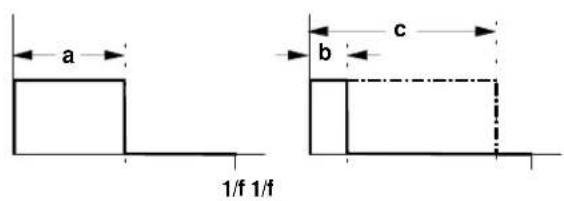
The VCO produces a square / rectangle wave at output / . You can alter its pulse width manually, or by voltage control (Pulse Width Modulation).
text_image
a b c 1/f 1/fFig 2: Square waves with different pulse widths
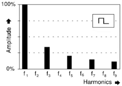
A symmetrical Pulse wave (i.e. an exact square wave, with a pulse width of 50 %), has only odd harmonics of its fundamental (see Fig. 3) and produces a typically hollow sound.
bar
| Harmonics | Amplitude (%) | | :--- | :--- | | f₁ | 100 | | f₂ | 0 | | f₃ | 35 | | f₄ | 0 | | f₅ | 25 | | f₆ | 0 | | f₇ | 20 | | f₈ | 0 | | f₉ | 15 |Fig. 3: Harmonic spectrum of a true square wave
The further the pulse width deviates from 50% (see Fig. 2, b and c), the weaker the lower harmonics become, and the more the sound gets thin and nasal.
Square waves are often used as a sound source in subtractive (filtered) synthesis, because of their rich overtones, and are good at producing woodwind-like timbres.
Triangle wave
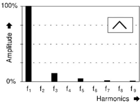
A triangle wave (VCO Output ( ) is poor in upper harmonics, and sounds softer and more mellow. It only contains odd harmonics, whose strength decreases exponentially - the third harmonic is a ninth as strong, the fifth 1/25, and so on.
bar
| Harmonics | Amplitude (%) | |---|---| | f₁ | 100 | | f₂ | 0 | | f₃ | 25 | | f₄ | 0 | | f₅ | 10 | | f₆ | 0 | | f₇ | 5 | | f₈ | 0 | | f₉ | 2 |Fig. 4: Harmonic spectrum of a triangle wave
Because of their soft, rounded timbre, triangle waves are ideal for synthesizing timbres like flute, organ and vibes.
Sine Wave
Sine waves are pure waves: they just contain the fundamental, without any harmonics (see Fig. 5). They are thus not suitable for subtractive synthesis (shaping sound with a filter).

bar
| Harmonics | Amplitude (%) | | :--- | :--- | | f₁ | 100 | | f₂ | 0 | | f₃ | 0 | | f₄ | 0 | | f₅ | 0 | | f₆ | 0 | | f₇ | 0 | | f₈ | 0 | | f₉ | 0 |Fig. 5: Spectrum of a sine wave
Frequency Modulation (FM)
Because the frequency of the VCO is controlled by the voltages at inputs " and §, Frequency Modulation is possible: frequency (pitch) is continuously varied by the voltages at the CV input/s.
For instance, if the frequency of the VCO is controlled by a slow LFO, you get typical vibrato (see Fig. 6).
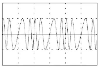
natural_image
Pure waveform diagram showing periodic oscillations without any text, numbers, or symbolsFig. 6: Frequency modulation using a slow LFO (Vibrato)
If the modulation frequency is in the audio range, completely different sounds emerge (see User Examples 6).
4. Controls
1 Range
Footage (the octave of the fundamental) is controlled with this knob. Five settings are available, giving a wide frequency range.
2 Tune
The TUNE control enables Fine Tuning of the oscillator frequency in a range of roughly ±12 Octave. For precise tuning, an electronic tuner is recommended.
P
If two or more oscillators are controlled by the same control voltages, and set to the same footage, you can use the TUNE knob to de-tune one or more of the oscillators relative to each other.
This can produce vibrato and chorus-like effects, perfect for soundscapes and generally rich timbres.
3 CV 2
The pitch of the VCO is controlled by the voltages present at inputs " and § . The amount the control voltage at input § affects VCO pitch can be controlled with Attenuator 3 (see also § ).
4 PW
You use control 4 to alter the pulse width of the square wave appearing at output & (see Fig. 2 and &).
5 PW CV 2
The pulse width of the square wave can also be altered or modulated by voltage control from inputs \$ and/or %. The level of the PW CV 2 (input %) affecting the pulse width can be set with gain control 5 (see also %).
5. In / Outputs
! SYNC
Socket ! is the Sync Input for the VCO. What sync means in this context is that the waveform of one VCO ("Slave") is locked to the waveform of another VCO ("Master"), by connecting the audio out of the master VCO to the Sync input of the slave VCO.
In the A-110, this is designed as "Hard Sync". Check out the following example (see Fig. 7): the slave VCO's sawtooth waveform is always reset to the beginning of a cycle whenever the master VCO's sawtooth waveform starts a new cycle. If f_M - the frequency of the master VCO - is higher than f_S (the slave's frequency), then the slave's pitch is synced exactly to the master's (Fig. 7a).
In the opposite situation, where the master VCO's pitch is lower than the slave ( f_M < f_S ), the master again imposes its frequency on the slave (Fig. 7 b: cycle T exactly matches the master VCO's cycle). But at the same time, harmonic sidebands are produced by the slave VCO's changed waveform, which can create interesting timbral effects.
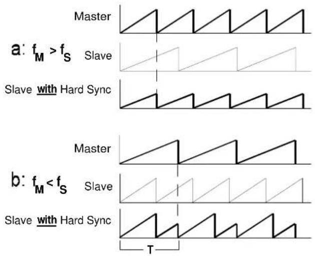
text_image
Master a: f_M > f_S Slave Slave with Hard Sync b: f_M < f_S Slave Slave with Hard Sync TFig. 7: Hard Sync on the A-110
" CV 1 · § CV 2
Sockets " and § are CV inputs for controlling the VCO's frequency (pitch). The voltages at these inputs are summed. The inputs follow the 1V / octave rule exactly.
Input " is normally connected to a control voltage governing pitch (for instance from a MIDI-CV interface, or a master keyboard with a 1V / octave output).
H
Socket CV 1 " is designed as a normalled socket, connected to whatever CV is present on the internal System Bus. This CV (for instance from a master keyboard) governs the VCO's pitch, unless a plug is inserted in socket".
If you put a control voltage (for instance from an LFO) into socket ", the System Bus is disconnected, and the VCO's pitch is controlled by this voltage.
As a rule, input § is used for FM - for vibrato, auto-bend, or other pitch-related effects; the level of control voltage passing to the VCO is adjusted with attenuator 3.
\$ PW CV 1 • % PW CV 2
Sockets \$ and % are the Voltage Control Inputs for the Pulse Width of the square wave that the VCO produces. These voltages are summed. The level of CV input % can be controlled with knob 5.
& ∧ / ∩ ( ∧ ) ∼
These four sockets are the VCO outputs: Sawtooth (&), Square (/ ), Triangle (( ) and Sine wave ( ) ).
Pitch is always the same for each of these outputs.
6. User examples
FM in the audio range
Using audio range oscillators for FM can produce interesting sounds. Thanks to the rapid changes in the modulated VCO's pitch, side bands are created: as well as the two original frequencies, you also get the frequencies created by their sum and difference (for instance, a modulation frequency of 100 Hz and a carrier frequency of 500 Hz produce side bands at 400 Hz and 600 Hz).

flowchart
graph TD
    subgraph Module_A
        A1["A-110 VCO"] -->|CV 1| B1
        B1 --> C1
        C1 --> D1
        D1 --> E1
        E1 --> F1
        F1 --> G1
    end
    subgraph Module_B
        A2["A-110 VCO"] -->|CV 2| B2
        B2 --> C2
        C2 --> D2
        D2 --> E2
        E2 --> F2
        F2 --> G2
        G2 --> H2
    end
    style Module_A fill:#f9f,stroke:#333
    style Module_B fill:#bbf,stroke:#333
Fig. 8: Frequency modulation in the audio range
When you try this out (see Fig. 8), start off with sine waves, and slowly raise the modulation frequency from the sub-audio into the audio range.
If you use waveforms other than sine waves in FM in the audio range, the sounds that result will be extremely complex and difficult to predict. A sawtooth, for instance, can be looked upon as a vast number of sine waves of different frequencies - all of which will be represented in the modulated output, so that the final sound will be a complex mix of the buzzes, noises and tones produced by all the various sum and difference outputs.
H The FM in the A-110 is exponential (as opposed to linear) FM. This means that changes in control voltage produce proportional changes in the pitch relationship of the component sounds.
With FM in the audio range, this can lead to undesirable side-effects. If, for instance, a 440 Hz sine wave is modulated by another with twice the amplitude, the maximum frequency of the modulated signal will be 880 Hz, and the minimum will be 220 Hz (see Fig.9).
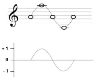
text_image
Musical notation and corresponding sine wave graph showing pitch, rhythm, and amplitude relationshipsFig. 9: exponential FM using the A-110
With FM in the audio range, the ear doesn't resolve these octave transitions, but hears the whole sound as a very full and rather weird composite, with the middle frequency clearly at odds with the carrier frequency.
Whenever you change pitch using exponential FM, the inevitable side effect of the change will be an unplanned and un-musical change in the relative pitch of the components of the sound!
In circumstances where this pitch-shift is not wanted, you need to use an A-111 High-End VCO instead of the A-110, because it has the benefit of linear FM, and can thus avoid this problem.
Tone colour changes using VCO SYNC
Very interesting sounds can be created by syncing together two VCOs (see p.7), using sub-audio frequency modulation (eg. with an LFO) on the slave VCO, and a mixer to add to the excitement by subtly varying the level of each VCO (see Fig. 10).
Try different settings for the slave and master VCO, as well as varying the FM amount. You'll be amazed at the complexity and amount of variation over time of the overtones created.
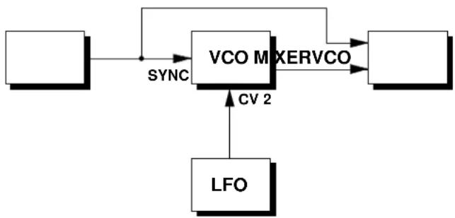
flowchart
graph TD
    A[" "] -->|SYNC| B["VCO Mixer"]
    B -->|XERVCO| C[" "]
    B -->|CV 2| D["LFO"]
    D -->|LV| B
Fig. 10: Tone colour changes using VCO SYNC
Pulse Width Modulation
If you modulate the pulse width of a square wave with an LFO or ADSR (Pulse Width Modulation, or PWM), the harmonic spectrum constantly changes (see p.3, 4). Even with just one oscillator, you can create a dense timbre with internal movement, in some ways similar to vibrato, and otherwise only available by using two oscillators fractionally de-tuned from each other.
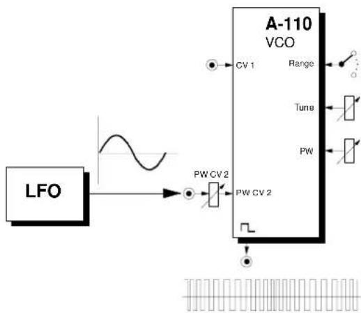
flowchart
graph LR
    LFO --> A["Waveform"]
    A --> B["A-110 VCO"]
    B --> C["CV 1"]
    B --> D["Range"]
    B --> E["Tune"]
    B --> F["PW"]
    B --> G["PW CV 2"]
    B --> H["PW CV 2"]
Fig. 11: Pulse Width Modulation using an LFO
VCO and DIVIDER
Using a divider like the A-115, you can synthesize up to three square-wave sub-octaves, and mix them with the original signal at any level you choose.
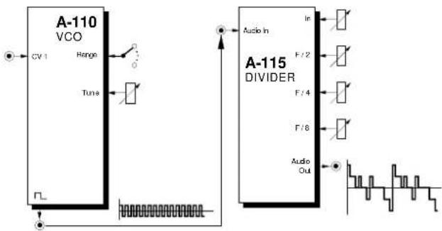
text_image
A-110 VCO CV 1 Hange Tune A-115 DIVIDER Audio In F / 2 F / 4 F / 8 Audio OutFig. 12: Using the DIVIDER to add sub-octaves
VCO and WAVEFORM PROCESSOR
With a WAVEFORM PROCESSOR you can alter the symmetry of the VCO's waveform and positively distort it, to construct new waveforms.
7. Patch-Sheet
The following diagrams of the module can help you recall your own Patches. They're designed so that a complete 19" rack of modules will fit onto an A4 sheet of paper.
Photocopy this page, and cut out the pictures of this and your other modules. You can then stick them onto another piece of paper, and create a diagram of your own system.
Make multiple copies of your composite diagram, and use them for remembering good patches and set-ups.
P
- Draw in patchleads with colored pens.
- Draw or write control settings in the little white circles.

text_image
A-110 VCO STANDARD VCO SYNC -2 Range +2 CV 1 Tune CV 2 CV 2 PW CV 1 PW PW CV 2 PW CV 2 0 10 0 10 0 10 0 10