A-125 - Synthesizer Doepfer - Free user manual and instructions
Find the device manual for free A-125 Doepfer in PDF.

| Product Type | Eurorack Synthesizer Module |
| Brand | Doepfer |
| Model | A-125 |
| Category | Voltage Controlled Oscillator (VCO) |
| Width | 8 HP (40.3 mm) |
| Height | 3U (128.5 mm) |
| Depth | 30 mm (approx.) |
| Weight | 95 g |
| Power Supply | +12V: 30 mA, -12V: 20 mA |
| Output Waveforms | Sine, Triangle, Sawtooth, Square (with PWM) |
| Frequency Range | 8 Hz to 8 kHz (approx.) |
| CV Inputs | FM, PWM, 1V/Oct |
| Controls | Coarse Frequency, Fine Tune, PWM Depth |
| Output Level | ±5V (approx.) |
| LED Indicator | Yes (power and output activity) |
| Protection | Reverse power polarity protection |
| Compliance | RoHS, CE |
| Maintenance | Clean with dry cloth; avoid liquids |
| Spare Parts | Available from Doepfer or authorized dealers |
| Repair | Contact Doepfer support or certified repair centers |
Frequently Asked Questions - A-125 Doepfer
User questions about A-125 Doepfer
0 question about this device. Answer the ones you know or ask your own.
Ask a new question about this device
Download the instructions for your Synthesizer in PDF format for free! Find your manual A-125 - Doepfer and take your electronic device back in hand. On this page are published all the documents necessary for the use of your device. A-125 by Doepfer.
USER MANUAL A-125 Doepfer
flowchart
graph TD
    A["Level"] --> B["Audio In"]
    B --> C["Audio Out"]
    D["CV"] --> E["CV"]
    F["CV 2"] --> G["Shift"]
    H["Resonance"] --> I["Mix"]
    J["Audio Out"] --> K["Switch"]
1. Introduction
Module A-125 (VC Phaser) is a voltage controlled phase shifter.
Phase shifting can be controlled either manually or by voltage control.
Other parameters which can be controlled are resonance (governing the depth of the comb filtering, and tonal color - see page 3) and mix (the amount of the original signal which is added to the phase-shifted signal).
2. VC Phaser - Overview
text_image
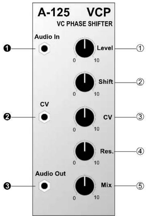
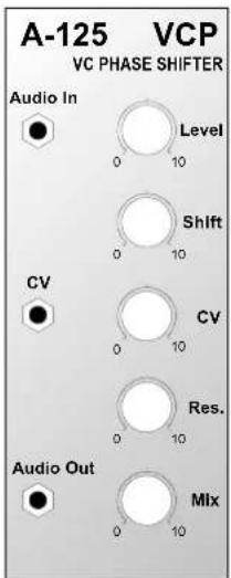
A-125 VCP VC PHASE SHIFTER Audio In Level ① 0 10 Shift ② 0 10 CV CV ③ 0 10 Res. ④ 0 10 Audio Out Mix ⑤ 0 10Controls:
① Level: Attenuator to control the level of the signal at input ①
② Shift: Control for manually setting the amount of phase shift
③ CV : Attenuator for the phase shift voltage control signal at input ②
④ Res.: Resonance control
⑤ Mix : Control for setting the amount of the original signal added to the phase-shifted signal
In / Outputs:
① Audio In : Audio input
② CV : Input for pitch-shift voltage control
③ Audio Out : Audio output
3. Basic principles
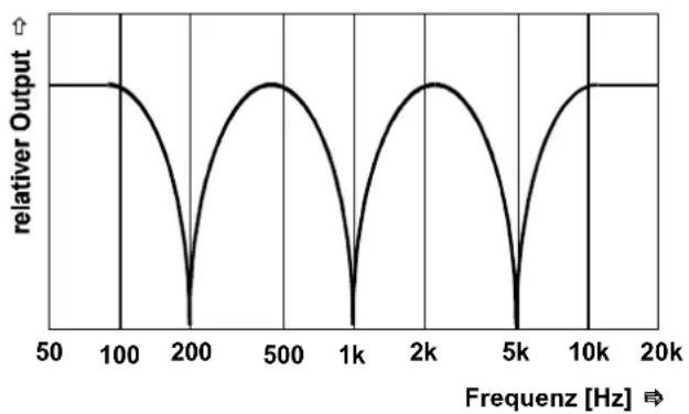
The phasing process relies on dynamic comb filtering. The comb filtering produces a series of gaps in the audio spectrum (in Fig. 1, at 200 Hz, 1 kHz and 5 kHz), by the cancelling process which is created by having identical sounds 180^ out of phase with each other (or 'inverted').
line
| Freqenz [Hz] | relativer Output | | ------------ | ---------------- | | 50 | 0 | | 100 | 0 | | 200 | 0 | | 500 | 0 | | 1k | 0 | | 2k | 0 | | 5k | 0 | | 10k | 0 | | 20k | 0 |Fig. 1: The principle of phasing
These zero points are continuously swept through the audio spectrum, cancelling out different frequencies, and producing the characteristic phasing sound.
The principle can be explained by looking at the diagram (Fig. 2) of a phaser created by three band pass filters. Here, audio is input to the three filters BP1 to BP3 (notch filters also work), set to different middle frequencies. A slow LFO modulates the frequencies.
The outputs of the band pass filters are then mixed with the original signal. Because of the phase reversal inherent in the filter design (most apparent close to the middle frequency), different areas of the audio spectrum are cancelled out.

flowchart
graph TD
    A["Audio In"] --> B["BP 1 f_c = x Hz"]
    C["LFO"] --> D["BP 2 f_c = y Hz"]
    C --> E["BP 3 f_c = z Hz"]
    B --> F["Mixer"]
    D --> F
    E --> F
    F --> G["Out"]
    H["f ~ 3 Hz"] --> C
Fig. 2: A phaser model using separate modules
4. Controls
① Level
Attenuator ① controls the level of the input signal.
② Shift
Phase shift amount is controlled with this knob, in a range from around 0^ to 180^ .
③ CV
As well as manual phase shifting, a control voltage at input ② can modulate the shift. Attenuator ③ sets the level of voltage control.
As a rule, a slowly changing signal (eg LFO, ADSR, Random, etc.) is used for this modulation.
④ Res.
This knob controls the resonance - the amount of the output signal fed back to the input. With this you can control the exact depth of the signal cancellation (see Fig. 1). The resonance parameter controls the tone-colour of the sound; you can't use resonance to make the phaser self-oscillate like on a VCF.
⑤ Mix
Use control ⑤ to determine the exact balance of phase-shifted and original signal. From minimum to maximum produces the following:
Mix = 0 : just phase-shifted signal - "phase / vibrato": the signal sounds somehow skewed.
Mix = 10 : 50% phase-shifted + 50% original signal - phasing: typical swooshy phaser sound.

Try out different settings for resonance and mix, to see how what effect these parameters have on the sound.
5. In / Outputs
① Audio In
Socket ① is the phaser's audio input.
② CV
The control voltage for modulating the speed of phase shifting is input at socket ②. You can set the level of this CV with control ③.
③ Audio Out
Output ③ has the mix of phase-shifted and original signals determined by the position of control ⑤.
6. User examples
Standard set-up
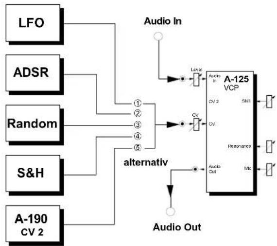
Fig. 3 shows a typical patch, with various alternative sources of slow-changing modulators affecting the speed of the phase sweep.
flowchart
graph TD
    LFO --> A["Alternative Switch"]
    ADSR --> A
    Random --> A
    S&H --> A
    A --> A1["Level"]
    A1 --> A2["Audio In"]
    A2 --> A3["VCP"]
    A3 --> A4["CV 2"]
    A3 --> A5["Shift"]
    A3 --> A6["Resonance"]
    A3 --> A7["Audio Out"]
    A4 --> A8["CV"]
    A5 --> A9["CV"]
    A6 --> A10["Resonance"]
    A7 --> A11["Audio Out"]
    A8 --> A12["Output"]
    A9 --> A13["Output"]
    A10 --> A14["Output"]
    A11 --> A15["Output"]
    A12 --> A16["Output"]
Fig. 3: Typical phaser application
The phaser is simply inserted in the audio path like this. For modulation sources, you could use, for instance, any of the following:
| Alternative | Module | Adjustment Effect | |
| 1 | LFOA-145 | low frequency (< 2 Hz) | free-running phase-shift |
| 2 | ADSRA-140 | slow envelope | keyboard-controlled phaser |
| 3 | Random A-118 | slow random rate | random phasing |
| 4 | S&HA-148 | random phasing | |
| 5 | A-190CV 2 | any MIDI controller for CV 2 (eg. velocity) | MIDI - controlled phasing |

With the last two of these alternative modulators particularly, you can optionally use an A-170 Slew Limiter after them, to smooth out sudden jumps of control voltage, and make the phasing transitions less abrupt.
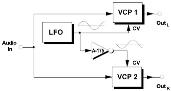
"Stereo"-Phasing
Using two A-125s and the patch in Fig. 4 you can create a wide pseudo-stereo phasing effect, with inverted signals coming out of each of the two audio channels ( Out_L und Out_R ).
Typically, you can use a slow LFO to provide the modulation for the phase shift, but any other modulator will work, as with standard phasing. Phaser VCP 1 is fed the modulation from the LFO directly, while an A-175 voltage inverter is patched in before the second phaser VCP 2, to invert the modulation.
flowchart
graph TD
    A["Audio In"] --> B["LFO"]
    B --> C["VCP 1"]
    C --> D["Out_L"]
    B --> E["A-175"]
    E --> F["VCP 2"]
    F --> G["Out_R"]
    C --> H["CV"]
    F --> I["CV"]
    H --> J["Waveform"]
    I --> K["Waveform"]
Fig. 4: "Stereo" phasing
7. Patch-Sheet
The following diagrams of the module can help you recall your own Patches. They're designed so that a complete 19" rack of modules will fit onto an A4 sheet of paper.
Photocopy this page, and cut out the pictures of this and your other modules. You can then stick them onto another piece of paper, and create a diagram of your own system.
Make multiple copies of your composite diagram, and use them for remembering good patches and set-ups.

- Draw in patchleads with colored pens.
- Draw or write control settings in the little white circles.
text_image
A-125 VCP VC PHASE SHIFTER Audio In Level 0 10 Shift 0 10 CV CV 0 10 Res. 0 10 Audio Out Mix 0 10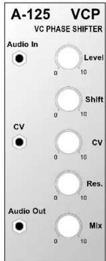
text_image
A-125 VCP VC PHASE SHIFTER Audio In Level 0 10 Shift 0 10 CV CV 0 10 Res. 0 10 Audio Out Mix 0 10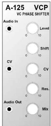
text_image
A-125 VCP VC PHASE SHIFTER Audio In Level Shift CV CV Res. Audio Out Mix
A-125 VC Phaser
System A - 100
DOEPFER