A-143-1 - Synthesizer Doepfer - Free user manual and instructions
Find the device manual for free A-143-1 Doepfer in PDF.

User questions about A-143-1 Doepfer
0 question about this device. Answer the ones you know or ask your own.
Ask a new question about this device
Download the instructions for your Synthesizer in PDF format for free! Find your manual A-143-1 - Doepfer and take your electronic device back in hand. On this page are published all the documents necessary for the use of your device. A-143-1 by Doepfer.
USER MANUAL A-143-1 Doepfer
flowchart
graph TD
    A["preceding Comp.Out"] --> B["AD/LFO 1"]
    B --> C["Trig.In"]
    C --> D["Attack"]
    D --> E["Decay"]
    E --> F["Mix Polarizer"]
    F --> G["Threshold"]
    G --> H["Mode AD/LFO"]
    H --> I["AD/LFO 2"]
    I --> J["(same as above)"]
    I --> K["AD/LFO 3"]
    K --> L["(same as above)"]
    K --> M["AD/LFO 4"]
    M --> N["(same as above)"]
    N --> O["Mixer"]
    O --> P["Mix Out"]
    style A fill:#f9f,stroke:#333
    style P fill:#f9f,stroke:#333
Fig. 1: A-143-1 Controls, Inputs and Outputs
1. Introduction
Module A-143-1 contains four independent Attack/Decay generators. When the module is used as a complex envelope generator, then two, three or four units are daisy-chained, i.e. the preceding unit triggers the following unit. But the four units can be used even as four separate AD generators (mode switch in position AD) or free-running AD-type LFOs (mode switch in position LFO). The LFO mode differs in several points from a regular LFO (e.g. A-145, A-146 or A-147), as the slopes are exponential - in contrast to linear slopes of a normal LFO. In addition the frequency is defined by both controls, as the attack control defines the duration of the rising slope, while the decay control defines the duration of the falling slope.
Each unit has available a comparator that compares the AD output voltage against a manually adjustable threshold and turns on the corresponding comparator output as soon as the AD output voltage goes below the threshold level during the decay phase. The comparator outputs are normalled to the trigger inputs of the following stage via the switching contacts of the trigger input sockets. Consequently the first unit triggers the second, the second triggers the third and so on (and the last unit triggers the first one).
Each AD/LFO unit also offers a polarizer control. This allows adding or subtracting all AD/LFO signals to the mix output with adjustable level. Additionally each unit features a single envelope output and a digital "End Of Attack (EOA)" output, that indicates the end of the attack phase.
2. Basic Principles
Fig. 2 shows the basic function of each unit:

text_image
Trig. In falling edge does not matter ENV Out Threshold Cp Out EOA OutFig. 2: Basic function
The positive edge of the trigger input starts the envelope signal and resets the "End of Attack (EOA)" output. The time for the rising slope of the envelope is defined by the Attack control. As soon as the maximum value (about +8 V) is reached, the EOA output is set to "high" and the decay state begins. The time for the falling slope of the envelope is defined by the Decay Control.
The threshold setting defines the behaviour of the Comparator output (Cp Out). This output turns "low" as soon as the level of the envelope signal exceeds the threshold level. Otherwise it's high.
Both digital outputs EOA and Cp Out can be used to trigger other A-100 modules or other units of the A-143-1.
The retrigger behaviour of the A-143-1 is different compared to other envelope generators. During the rising slope of the envelope (attack phase) the envelope cannot be retriggered or reset. And during the falling slope (decay phase) the direction changes if a trigger signal appears (changes from decay to attack state).
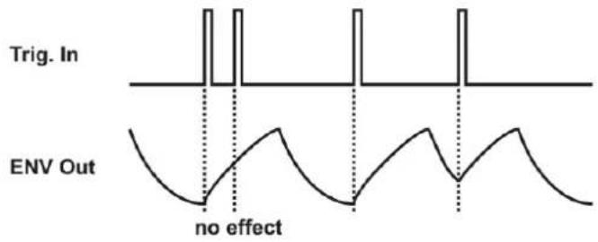
text_image
Trig. In ENV Out no effectFig. 3: Retrigger behaviour
DOEPFERSystem A-100 Quad AD/LFO A-143-1
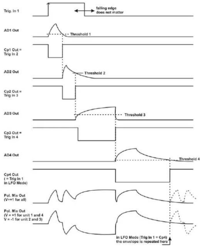
Provided that the trigger inputs are not patched the four units are daisy chained via the comparator outputs (Cp Out) as they are normalled via the switching contacts of the trigger input sockets, i.e. each unit is triggered by the Cp output of the preceding unit. Fig. 4 shows both the behaviour of the module in the default state (complex/multi-state LFO) and with a trigger signal applied to trigger input 1 (complex envelope generator).
The rising edge of Cp1 triggers the unit 2, the rising edge of Cp2 triggers the unit 3 and so on. The example uses different Attack, Decay and Threshold settings for each unit.
At the bottom of the picture two possible mixes are shown: For the first mix all envelope signals are added up with the same level and polarity (+1), i.e. all polarizer controls are in the fully clockwise position. For the second mix the level/polarity is +1 for the units 1 and 4, and -1 for the units 2 and 3, i.e. the polarizer controls of unit 1 and 4 are fully clockwise and the polarizer controls of unit 2 and 3 are fully counter-clockwise.
The dashed lines at the right end of the mix graphs are valid if the module is in the cyclic mode, i.e. if the comparator output 4 is normalled to the trigger input 1 (i.e. default without external trigger signal). The permanent lines are valid if an external trigger signal is used to trigger unit 1 (i.e. the daisy chain is interrupted at trigger input 1).
text_image
Trig. In 1 falling edge does not matter AD1 Out Threshold 1 Cp1 Out = Trig In 2 AD2 Out Threshold 2 Cp2 Out = Trig In 3 AD3 Out Threshold 3 Cp3 Out = Trig In 4 AD4 Out Threshold 4 Cp4 Out ( = Trig In 1 In LFO Mode) Pol. Mix Out (V=+1 for all) Pol. Mix Out (V = +1 for unit 1 and 4 V = -1 for unit 2 and 3) In LFO Mode (Trig In 1 = Cp4) the envelope is repeated hereFig. 4: Complex envelope generator / LFO
- Overview

text_image
A-143-1 Complex Envelope Generator / LFO Trig. EOA Mode Attack Env1 Decay Mix Polarizer Threshold Comp. Mix Out In ② ③ ④ ⑤ Cp4 AD Env2 Env3 Env4 Env4 LFO ① ② ③ ④ ⑤ ⑦ ⑧ Env1 Env2 Env3 Env4 Env5 Cp1 Env1 Cp2 Env2 Cp3 Env3 Cp4 Env4 DOEPFERFig. 5: A-143-1 front panel
Controls:
① AD/LFO : mode switch
② Attack: attack control (rising slope)
③ Decay: decay control (falling slope)
④ Mix Polarizer: polarizer control
⑤ Threshold: threshold control for comparator
⑥ : envelope display (LED)
⑦ : comparator output display (LED)
Inputs and Outputs:
① Trig. In : trigger input
normalled to Cp 4 for unit 1
normalled to Cp 1 for unit 2
normalled to Cp 2 for unit 3
normalled to Cp 3 for unit 4
② EOA : end of attack output
③ Env x: envelope output (x = 1...4)
④ Cp x: comparator output (x = 1...4)
⑤ Mix Out: mix output
The controls and outputs are the same for all four units.
Module width: 28 HP / 141.9 mm
Module current: 70 mA
3. Controls, Inputs and Outputs
① Trig. In : trigger input
Socket 1 is the trigger input of the corresponding unit. The positive edge of this signal triggers the AD generator. If the unit in question is used as an LFO, a dummy cable or jack plug can be patched into this socket. Otherwise the LFO is retriggered by the comparator output Cp of the preceding unit because of the normalling of the trigger socket (for details concerning the retrigger function please refer to page 2).
The trigger inputs ① are normalled in that way:
- Trigger input #1 is normalled to Cp #4
- Trigger input #2 is normalled to Cp #1
- Trigger input #3 is normalled to Cp #2
- Trigger input #4 is normalled to Cp #3
Provided that the four mode switches ① are set to AD and the trigger inputs ① are left open the module works as a complex 8-stage LFO with four adjustable rise and fall times (A/D controls ② and ③), segment levels (mix polarizer controls ④) and segment distances (threshold controls ⑤).
① AD/LFO : mode switch
This switch defines the function of the corresponding unit. In the upper position (AD) the envelope mode is selected, in the lower position (LFO) the free-running mode.
Remark: In LFO mode a dummy cable or jack plug should be inserted into the trigger input of the corresponding unit. Otherwise the Cp output of the preceding unit will retrigger the LFO (see page 2) because of the normalled trigger socket. This is of course only important if this special retrigger behaviour is not desired.
② Attack: attack control (rising slope)
③ Decay: decay control (falling slope)
These controls set the attack time and the decay time. The voltage at the envelope output ③ rises to the maximum, in a time determined by the setting of the attack knob. After the attack phase is finished, the voltage falls down to zero, in a time determined by the setting of the decay knob.
③ Env x: envelope output (x = 1...4)
⑥ : envelope display (LED)
Socket ③ is the envelope output of the corresponding unit. The LED ⑥ displays the envelope's course. The voltage range is about 0...+8V in the AD mode, +0.5...+8V in the LFO mode.
DOEPFERSystem A-100 Quad AD/LFO A-143-1
④ Mix Polarizer: polarizer control
This control is used to add or subtract the envelope signal of the corresponding unit to/from the mix signal appearing at output ⑤. This control is a so-called polarizer. The neutral position of the polarizer knob is at its center (0). Left from the center (area marked with a minus sign) the envelope signal of the unit is subtracted from the mix signal. Right from the center (area marked with a plus sign) the envelope signal of the unit is added to the mix signal. The distance from the center position determines the adding/subtracting level.
⑤ Threshold: threshold control for comparator
④ Cp x: comparator output (x = 1...4)
⑦ : comparator output display (LED)
The threshold control ⑤ is used to adjust the threshold level of the comparator. The threshold setting defines the behaviour of the corresponding comparator output (Cp x). This output turns "low" as soon as the level of the envelope signal exceeds the threshold level. Otherwise it's high. Please refer to the page 2 for details.
② EOA : end of attack output
This is the digital End Of Attack output (EOA). The EOA output is low during the attack stage and high otherwise. It can be used to trigger other A-100 modules or other units of the A-143-1.
⑤ Mix Out: mix output
This is the sum output where all envelope signals are added or subtracted in accordance to the corresponding polarizer controls. It can be used as a complex envelope signal (all mode switches in AD position and an external trigger signal connected to one of the trigger inputs) or as complex LFO (same as before, but no trigger signal connected to one of the trigger inputs).
4. User Examples
The A-143-1 is suitable for all kinds of modulations where normally LFOs or envelope generators are used. Please refer to the user manuals of other envelope generators or LFOs for details (i.e. all A-14x modules).
The units of the A-143-1 can be used as single devices or several units can be combined to obtain complex envelopes or LFOs. In principle any control voltage input can be controlled by the A-143-1 to modulate the parameter in question. Typical applications are:
• VCO Pitch/Frequency Modulation
Pitch/frequency modulation of a VCO produces vibrato.
• VCO Pulse Width Modulation
Pulse width modulation of a VCO produces cyclical variation in tone colour (sounds similar to phasing)
• VCA Loudness Modulation
Modulation of the gain of a VCA produces Tremolo
• VCF Frequency or Resonance Modulation
Modulation of the cut-off frequency of a VCF produces cyclical variation in tone colour. For some filters even the resonance can be modulated.
• VCP Phase Shift Modulation
Phase shift modulation of a phaser (e.g. A-101-3 or A-125) produces cyclic phasings or phase vibrato
By means of the universal vactrol module A-101-9 the parameters A and D can be voltage controlled. Please refer to the A-101-9 manual for details.
A special application of the quad AD generator is the subsequent control of up to four similar modules (e.g. VCAs, VCFs, VC phasers, VC flangers, VC frequency shifters ...) for quadrophonic sounds:

flowchart
graph TD
    A["A-143-1\nEnvelope Out 4\nEnvelope Out 3\nEnvelope Out 2\nEnvelope Out 1"] --> B["CV In\nAudio\nAudio\nIn\nVCA/VCF/VCP"]
    B --> C["Audio\nChannel #1"]
    A --> D["CV In\nAudio\nAudio\nIn\nVCA/VCF/VCP"]
    D --> E["Audio\nChannel #2"]
    A --> F["CV In\nAudio\nAudio\nIn\nVCA/VCF/VCP"]
    F --> G["Audio\nChannel #3"]
    A --> H["CV In\nAudio\nAudio\nIn\nVCA/VCF/VCP"]
    H --> I["Audio\nChannel #4"]