
JM82K - Power Tools RYOBI - Free user manual and instructions
Find the device manual for free JM82K RYOBI in PDF.

| Product Type | Biscuit Joiner |
| Brand | RYOBI |
| Model | JM82K |
| Power | 120 V, 60 Hz, AC only, 6.0 A |
| No Load Speed | 10,000 /min |
| Cutting Depth | 0 to 14.3 mm (0 to 9/16 in) |
| Fence Angle | 0° to 135° |
| Fence Height | 0 to 50.8 mm (0 to 2 in) |
| Blade | Tungsten Carbide, 101.6 mm (4 in), 8 teeth |
| Blade Size | 101.6 mm (4 in) |
| Cord Length | 3 m (10 ft) |
| Net Weight | 3.8 kg (8.4 lb) |
| Tool Dimensions (L x W x H) | Approx. 32 x 18 x 18 cm |
| Double Insulated | Yes |
| Main Functions | Cutting oval slots for biscuit joining, grooving, butt joint, miter joint, T-joint |
| Depth Adjustment | Knurled with detents for biscuits #0, #10, #20 |
| Height Adjustment | Knob with graduated scale |
| Angle Adjustment | Pivoting fence with 45° stops, knob clamping |
| Dust Collection | Removable dust bag, vacuum adapter (1-1/4 in) |
| Handle | Dual grip (rear) |
| Non-slip surface | On the fence |
| Cut line indicator | Center marks on the base |
| Biscuits provided | 20 biscuits #10 |
| Maintenance | Regular cleaning of dust path, blade replacement |
| Safety | Safety glasses required, double insulation, automatic motor stop |
Frequently Asked Questions - JM82K RYOBI
User questions about JM82K RYOBI
0 question about this device. Answer the ones you know or ask your own.
Ask a new question about this device
Download the instructions for your Power Tools in PDF format for free! Find your manual JM82K - RYOBI and take your electronic device back in hand. On this page are published all the documents necessary for the use of your device. JM82K by RYOBI.
USER MANUAL JM82K RYOBI
Your biscuit joiner has been engineered and manufactured to Ryobi's high standard for dependability, ease of operation, and operator safety. When properly cared for, it will give you years of rugged, trouble-free performance.

WARNING: To reduce the risk of injury, the user must read and understand the operator's manual before using this product.
Thank you for buying a Ryobi product.
TABLE OF CONTENTS
Introduction 2
General Safety Rules 3
■ Specific Safety Rules. 4
Symbols. 5-6
■ Electrical 7
Features. 8-9
Assembly 10
■ Operation 11-19
Adjustments 20
■ Maintenance. 20-23
■ Accessories 24
Troubleshooting 24
Parts Ordering / Service 26
INTRODUCTION
This tool has many features for making its use more pleasant and enjoyable. Safety, performance, and dependability have been given top priority in the design of this product making it easy to maintain and operate.
GENERAL SAFETY RULES

WARNING:
Read and understand all instructions. Failure to follow all instructions listed below, may result in electric shock, fire and/or serious personal injury.
SAVE THESE INSTRUCTIONS
WORK AREA
■ Keep your work area clean and well lit. Cluttered benches and dark areas invite accidents.
- Do not operate power tools in explosive atmospheres, such as in the presence of flammable liquids, gases, or dust. Power tools create sparks which may ignite the dust or fumes.
- Keep bystanders, children, and visitors away while operating a power tool. Distractions can cause you to lose control.
ELECTRICAL SAFETY
- Double insulated tools are equipped with a polarized plug (one blade is wider than the other). This plug will fit in a polarized outlet only one way. If the plug does not fit fully in the outlet, reverse the plug. If it still does not fit, contact a qualified electrician to install a polarized outlet. Do not change the plug in any way. Double insulation eliminates the need for the three-wire grounded power cord and grounded power supply system.
- Avoid body contact with grounded surfaces such as pipes, radiators, ranges, and refrigerators. There is an increased risk of electric shock if your body is grounded.
- Don't expose power tools to rain or wet conditions. Water entering a power tool will increase the risk of electric shock.
- Do not abuse the cord. Never use the cord to carry the tools or pull the plug from an outlet. Keep cord away from heat, oil, sharp edges, or moving parts. Replace damaged cords immediately. Damaged cords increase the risk of electric shock.
- When operating a power tool outside, use an outdoor extension cord marked "W-A" or "W". These cords are rated for outdoor use and reduce the risk of electric shock.
PERSONAL SAFETY
- Stay alert, watch what you are doing and use common sense when operating a power tool. Do not use tool while tired or under the influence of drugs, alcohol, or medication. A moment of inattention while operating power tools may result in serious personal injury.
-
Dress properly. Do not wear loose clothing or jewelry. Contain long hair. Keep your hair, clothing, and gloves away from moving parts. Loose clothes, jewelry, or long hair can be caught in moving parts.
-
Avoid accidental starting. Be sure switch is off before plugging in. Carrying tools with your finger on the switch or plugging in tools that have the switch on invites accidents.
- Remove adjusting keys or wrenches before turning the tool on. A wrench or a key that is left attached to a rotating part of the tool may result in personal injury.
- Do not overreach. Keep proper footing and balance at all times. Proper footing and balance enables better control of the tool in unexpected situations.
Use safety equipment. Always wear eye protection. Dust mask, nonskid safety shoes, hard hat, or hearing protection must be used for appropriate conditions. - Do not wear loose clothing or jewelry. Contain long hair. Loose clothes, jewelry, or long hair can be drawn into air vents.
- Do not use on a ladder or unstable support. Stable footing on a solid surface enables better control of the tool in unexpected situations.
TOOL USE AND CARE
- Use clamps or other practical way to secure and support the workpiece to a stable platform. Holding the work by hand or against your body is unstable and may lead to loss of control.
- Do not force tool. Use the correct tool for your application. The correct tool will do the job better and safer at the rate for which it is designed.
- Do not use tool if switch does not turn it on or off. Any tool that cannot be controlled with the switch is dangerous and must be repaired.
- Disconnect the plug from power source before making any adjustments, changing accessories, or storing the tool. Such preventive safety measures reduce the risk of starting the tool accidentally.
- Store idle tools out of the reach of children and other untrained persons. Tools are dangerous in the hands of untrained users.
- Maintain tools with care. Keep cutting tools sharp and clean. Properly maintained tools with sharp cutting edges are less likely to bind and are easier to control.
- Check for misalignment or binding of moving parts, breakage of parts, and any other condition that may affect the tool's operation. If damaged, have the tool serviced before using. Many accidents are caused by poorly maintained tools.
- Use only accessories that are recommended by the manufacturer for your model. Accessories that may be suitable for one tool, may become hazardous when used on another tool.
- Keep the tool and its handle dry, clean and free from oil and grease. Always use a clean cloth when cleaning. Never use brake fluids, gasoline, petroleum-based products, or any strong solvents to clean your tool. Following this rule will reduce the risk of loss of control and deterioration of the enclosure plastic.
GENERAL SAFETY RULES
SERVICE
-
Tool service must be performed only by qualified repair personnel. Service or maintenance performed by unqualified personnel may result in a risk of injury.
-
When servicing a tool, use only identical replacement parts. Follow instructions in the Maintenance section of this manual. Use of unauthorized parts or failure to follow Maintenance Instructions may create a risk of shock or injury.
SPECIFIC SAFETY RULES
Hold tool by insulated gripping surfaces when performing an operation where the cutting tool may contact hidden wiring or its own cord. Contact with a "live" wire will make exposed metal parts of the cutting tool "live" and shock the operator.
- Know your power tool. Read operator's manual carefully. Learn its applications and limitations, as well as the specific potential hazards related to this tool. Following this rule will reduce the risk of electric shock, fire, or serious injury.
Always wear safety glasses. Everyday eyeglasses have only impact-resistant lenses; they are NOT safety glasses. Following this rule will reduce the risk of serious personal injury.
- Protect your lungs. Wear a face or dust mask if the operation is dusty. Following this rule will reduce the risk of serious personal injury.
- Protect your hearing. Wear hearing protection during extended periods of operation. Following this rule will reduce the risk of serious personal injury.
- Inspect tool cords periodically and, if damaged, have repaired at your nearest Authorized Service Center. Constantly stay aware of cord location. Following this rule will reduce the risk of electric shock or fire.
- Check damaged parts. Before further use of the tool, a guard or other part that is damaged should be carefully checked to determine that it will operate properly and perform its intended function. Check for alignment of moving parts, binding of moving parts, breakage of parts, mounting, and any other conditions that may affect its operation. A guard or other part that is damaged should be properly repaired or replaced by an authorized service center. Following this rule will reduce the risk of shock, fire, or serious injury.
Make sure your extension cord is in good condition. When using an extension cord, be sure to use one heavy enough to carry the current your product will draw. A wire gauge size (A.W.G.) of at least 14 is recommended for an extension cord 50 feet or less in length. A cord exceeding 100 feet is not recommended. If in doubt, use the next heavier gauge. The smaller the gauge number, the heavier the cord. An undersized cord will cause a drop in line voltage resulting in loss of power and overheating. - Inspect for and remove all nails from lumber before using this tool. Following this rule will reduce the risk of serious personal injury.
- Save these instructions. Refer to them frequently and use them to instruct others who may use this tool. If you loan someone this tool, loan them these instructions also.

WARNING:
Some dust created by power sanding, sawing, grinding, drilling, and other construction activities contains chemicals known to cause cancer, birth defects or other reproductive harm. Some examples of these chemicals are:
- lead from lead-based paints,
crystalline silica from bricks and cement and other masonry products, and - arsenic and chromium from chemically-treated lumber.
Your risk from these exposures varies, depending on how often you do this type of work. To reduce your exposure to these chemicals: work in a well ventilated area, and work with approved safety equipment, such as those dust masks that are specially designed to filter out microscopic particles.
SYMBOLS
| Some of the following symbols may be used on this tool. Please study them and learn their meaning. Proper interpretation of these symbols will allow you to operate the tool better and safer. | ||
| SYMBOL | NAME | DESIGNATION/EXPLANATION |
| V | Volts | Voltage |
| A | Amperes | Current |
| Hz | Hertz | Frequency (cycles per second) |
| W | Watt | Power |
| min | Minutes | Time |
| ~ | Alternating Current | Type of current |
| == | Direct Current | Type or a characteristic of current |
| n0 | No Load Speed | Rotational speed, at no load |
| 回 | Class II Construction | Double-insulated construction |
| .../min | Per Minute | Revolutions, strokes, surface speed, orbits etc., per minute |
| Wet Conditions Alert | Do not expose to rain or use in damp locations. | |
| Read The Operator's Manual | To reduce the risk of injury, user must read and understand operator's manual before using this product. | |
| Eye Protection | Always wear safety goggles or safety glasses with side shields and a full face shield when operating this product. | |
| Safety Alert | Precautions that involve your safety. | |
| No Hands Symbol | Failure to keep your hands away from the blade will result in serious personal injury. | |
| No Hands Symbol | Failure to keep your hands away from the blade will result in serious personal injury. | |
| No Hands Symbol | Failure to keep your hands away from the blade will result in serious personal injury. | |
| No Hands Symbol | Failure to keep your hands away from the blade will result in serious personal injury. | |
| Hot Surface | To reduce the risk of injury or damage, avoid contact with any hot surface. | |
SYMBOLS
| The following signal words and meanings are intended to explain the levels of risk associated with this product. | ||
| SYMBOL | SIGNAL | MEANING |
| DANGER: | Indicates an imminently hazardous situation, which, if not avoided, will result in death or serious injury. | |
| WARNING: | Indicates a potentially hazardous situation, which, if not avoided, could result in death or serious injury. | |
| CAUTION: | Indicates a potentially hazardous situation, which, if not avoided, may result in minor or moderate injury. | |
| CAUTION: | (Without Safety Alert Symbol) Indicates a situation that may result in property damage. | |
SERVICE
Servicing requires extreme care and knowledge and should be performed only by a qualified service technician. For service we suggest you return the product to your nearest AUTHORIZATION SERVICE CENTER for repair. When servicing, use only identical replacement parts.

WARNING:
To avoid serious personal injury, do not attempt to use this product until you read thoroughly and understand completely the operator's manual. Save this operator's manual and review frequently for continuing safe operation and instructing others who may use this product.

WARNING:

The operation of any power tool can result in foreign objects being thrown into your eyes, which can result in severe eye damage. Before beginning power tool operation, always wear safety goggles or safety glasses with side shields and a full face shield when needed. We recommend Wide Vision Safety Mask for use over eyeglasses or standard safety glasses with side shields. Always use eye protection which is marked to comply with ANSI Z87.1.
SAVE THESE INSTRUCTIONS
ELECTRICAL
DOUBLE INSULATION
Double insulation is a concept in safety in electric power tools, which eliminates the need for the usual three-wire grounded power cord. All exposed metal parts are isolated from the internal metal motor components with protecting insulation. Double insulated tools do not need to be grounded.

WARNING:
The double insulated system is intended to protect the user from shock resulting from a break in the tool's internal insulation. Observe all normal safety precautions to avoid electrical shock.
NOTE: Servicing of a tool with double insulation requires extreme care and knowledge of the system and should be performed only by a qualified service technician. For service, we suggest you return the tool to your nearest authorized service center for repair. Always use original factory replacement parts when servicing.
ELECTRICAL CONNECTION
This tool has a precision-built electric motor. It should be connected to a power supply that is 120 volts, 60Hz , AC only (normal household current). Do not operate this tool on direct current (DC). A substantial voltage drop will cause a loss of power and the motor will overheat. If your tool does not operate when plugged into an outlet, double-check the power supply.
EXTENSION CORDS
When using a power tool at a considerable distance from a power source, be sure to use an extension cord that has the capacity to handle the current the tool will draw. An undersized cord will cause a drop in line voltage, resulting in overheating and loss of power. Use the chart to determine the minimum wire size required in an extension cord. Only round jacketed cords listed by Underwriter's Laboratories (UL) should be used.
When working outdoors with a tool, use an extension cord that is designed for outside use. This type of cord is designated with "WA" on the cord's jacket.
Before using any extension cord, inspect it for loose or exposed wires and cut or worn insulation.
**Ampere rating (on tool faceplate)
0-2.0 2.1-3.4 3.5-5.0 5.1-7.0 7.1-12.0 12.1-16.0
Cord Length
Wire Size (A.W.G.)
| 25' | 16 | 16 | 16 | 16 | 14 | 14 |
| 50' | 16 | 16 | 16 | 14 | 14 | 12 |
| 100' | 16 | 16 | 14 | 12 | 10 | - |
**Used on 12 gauge - 20 amp circuit.
NOTE: AWG = American Wire Gauge

WARNING:
Keep the extension cord clear of the working area. Position the cord so that it will not get caught on lumber, tools or other obstructions while you are working with a power tool. Failure to do so can result in serious personal injury.

WARNING:
Check extension cords before each use. If damaged replace immediately. Never use tool with a damaged cord since touching the damaged area could cause electrical shock resulting in serious injury.
FEATURES
PRODUCT SPECIFICATIONS
Fence Angle Adjustments 0-135°
Depth of Cut. 0-9/16 in.
Cord Length 10 ft.
Blade 4 in.
No Load Speed 10,000/min.
Input 120 V, 60 Hz, AC only, 6.0 Amps
Net Weight. 8.4 lbs.
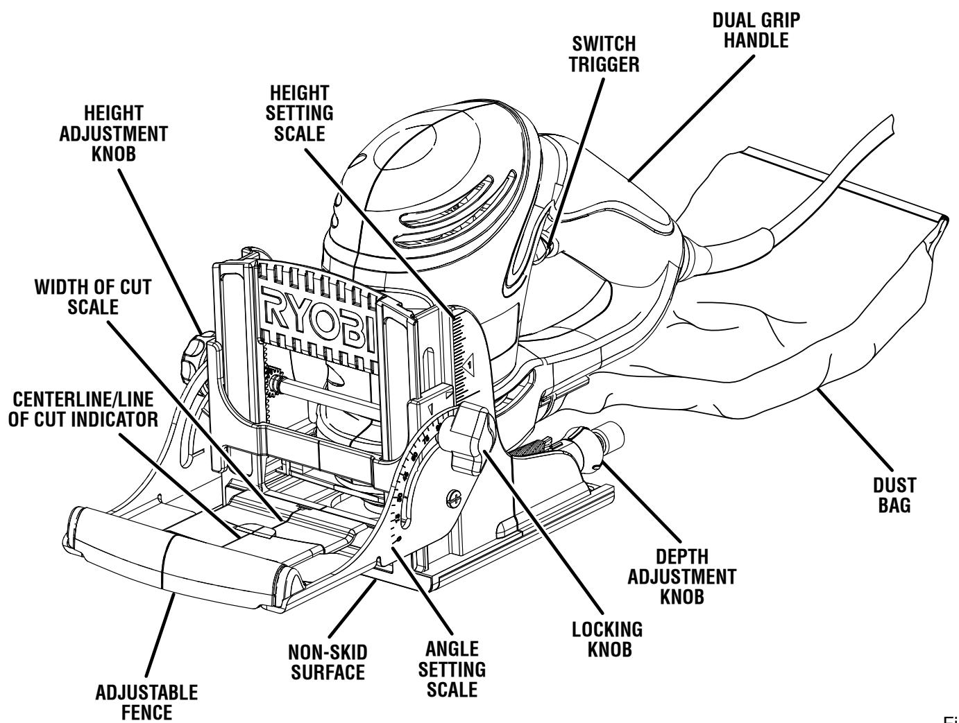
Fig. 1
KNOW YOUR BISCUIT JOINER
See Figure 1.
Before attempting to use this product, familiarize yourself with all operating features and safety rules.
SWITCH TRIGGER
The biscuit joiner has a conveniently located ON/OFF switch trigger on the underside of the dual grip handle.
CARBIDE-TIPPED BLADE
The biscuit joiner has an 8-tooth carbide-tipped blade for cutting biscuit slots.
NON-SKID SURFACE
The fence on the biscuit joiner has a non-skid surface to help prevent misalignment caused by skidding during use. It also prevents marring of the workpiece when making cuts.
DEPTH ADJUSTMENT KNOB
A spring-loaded depth adjustment knob makes it possible to make proper settings for three standard size biscuits.
HEIGHT SETTING SCALE
A scale on each side of the fence indicates the height of the fence from the center of the blade.
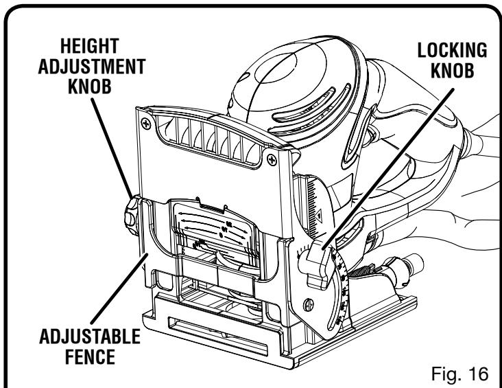
HEIGHT ADJUSTMENT KNOB
The height adjustment knob moves the adjustable fence up or down to adjust the height of the fence from the center of the blade.
LOCKING KNOB
The locking knob loosens the adjustable fence and allows movement of the height adjustment knob.
ANGLE SETTING SCALE
The adjustable fence on the biscuit joiner can be set at angles from 0^ to 135^ .
DUAL GRIP HANDLE
The dual grip handle offers a choice of two grip positions for operator comfort.
DUST COLLECTION
Wood particles are drawn up through a tunnel in the base and collect in the dust bag during cutting operations. The dust bag can be removed and a 1-1/4 in. vacuum can be attached to the dust port.
LINE OF CUT INDICATOR
Centerline and cut indicator marks help the operator make more accurate cuts.
ADJUSTABLE FENCE
The biscuit joiner has an adjustable fence for setting the angle from 0^ to 135^ , with positive stop settings in increments of 45^ . The height of the fence can be set between 0 in. -2 in.
The adjustable fence should always be used to guide and balance the biscuit joiner, providing ease of operation and maintaining control.
BISCUITS
Biscuits swell rapidly upon contact with water-based woodworking glues. They are available in three standard sizes:
0 (5/8 in. x 1-13/16 in.)
10 (13/16 in. x 2-1/16 in.)
20 (15/16 in. x 2-5/16 in.)
This biscuit joiner is packaged with 20 #10 biscuits.
UNPACKING
This product requires assembly.
- Carefully remove the tool and any accessories from the box. Make sure that all items listed in the packing list are included.
Inspect the tool carefully to make sure no breakage or damage occurred during shipping. - Do not discard the packing material until you have carefully inspected and satisfactorily operated the tool.
If any parts are damaged or missing, please call 1-800-525-2579 for assistance.
PACKING LIST
Biscuit Joiner
10 Biscuits (20)
Carrying Case
Operator's Manual
Warranty Registration Card

WARNING:
If any parts are missing do not operate this tool until the missing parts are replaced. Failure to do so could result in possible serious personal injury.

WARNING:
Do not attempt to modify this tool or create accessories not recommended for use with this tool. Any such alteration or modification is misuse and could result in a hazardous condition leading to possible serious personal injury.

WARNING:
Do not connect to power supply until assembly is complete. Failure to comply could result in accidental starting and possible serious personal injury.
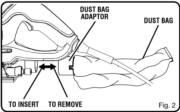
INSTALLING/REMOVING THE DUST BAG
See Figure 2.
The dust bag located on the rear of the biscuit joiner provides a dust collection system. Wood particles are drawn up through the base and collect in the dust bag during cutting operations. For more efficient operation, empty the dust bag when half full.
To install, slide the dust bag adaptor onto the dust port on the biscuit joiner. To remove the dust bag, grasp the adaptor and pull the dust bag away from the biscuit joiner.
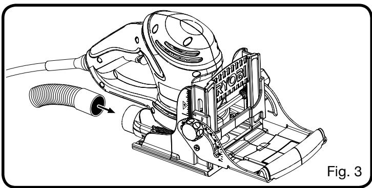
ATTACHING THE BISCUIT JOINER TO A VACUUM
See Figure 3.
The dust bag can be removed and a 1-1/4 in. vacuum can be attached to the dust port.
Unplug the biscuit joiner.
Remove the dust bag.
- Attach a vacuum hose to the dust port.
- Connect the biscuit joiner and the vacuum to a power supply.

WARNING:
When the tool is not connected to vacuum, always reinstall the dust bag back onto the tool. Failure to do so could cause dust or foreign objects to be thrown into your face or eyes which could result in possible serious injury.
OPERATION

WARNING:
Do not allow familiarity with tools to make you careless. Remember that a careless fraction of a second is sufficient to inflict serious injury.

WARNING:
Always wear safety goggles or safety glasses with side shields when operating power tools. Failure to do so could result in objects being thrown into your eyes resulting in possible serious injury.
APPLICATIONS
You may use this tool for the purposes listed below:
Cutting precise mating oval slots in hard wood, soft wood, plywood and particle board
SPLINE JOINERY
Spline joinery is one of the strongest methods of joinery used in woodworking. When glue is properly applied to a spline and to the joint area of the wood pieces being connected, a large surface area receives the adhesion properties of the glue. This forms a strong joint.
Traditional spline joinery requires cutting slots with a router or table saw. Small, thin strips of wood must then be cut to fit inside the slots and act as splines.
Newer methods of spline joinery use a plate or biscuit joiner to cut precise mating oval slots in adjoining boards. This biscuit joiner is a fast, simple, and accurate plunge-cutting tool that can be used to cut slots in hardwood, softwood, plywood, particle board, and other pressed woods.
Football shaped wafers, called biscuits, are then placed inside the slots with glue and used to help line up adjoining surfaces. When a water based glue is used, the biscuits swell in the joint, making an extremely strong and firm bond. White glue, yellow glue, carpenters glue, hide glue and aliphatic resin glue are examples of water-based glues. This bonding technique has traditionally been limited to making edge-to-edge joints. However, with the use of your new biscuit joiner, biscuits can now be easily used to connect butt, miter, and T-joints. Biscuit joining can be as strong as mortise and tenon, tongue and groove, standard spline, and doweled joints. In most cases the material around the biscuit will break before the biscuit itself will break. A greater surface area is exposed to glue in a biscuit joint, making the seams stronger.
A variety of spline joints can be made using the biscuit joiner. The number and size biscuits needed for each joint depends on the thickness of the wood and the length of the joint. In general, the small #0 biscuits should be used for miter cuts in 3/4 in. materials. The larger biscuits should be used for edge-to-edge joinery.
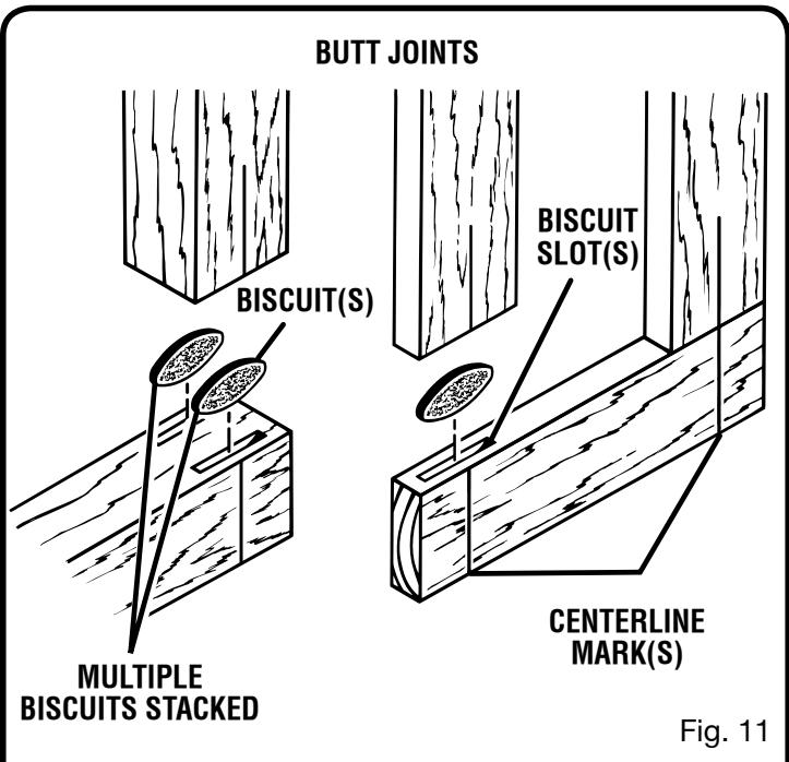
When joining 1-1/2 in. thick materials, stack two biscuits, one above the other. For example, use this method when joining 2 in. x 4 in. dressed lumber. When joining even thicker materials, use additional biscuits, stacked above each other.
When making edge-to-edge joints for tabletops, workbenches, cutting boards, etc. the more biscuits you use, the stronger the joint will be.
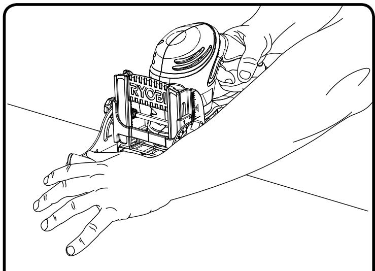
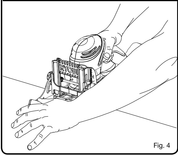
TURING ON/OFF THE BISCUIT JOINER
See Figure 4.
To turn on the biscuit joiner, depress the switch trigger. Release the switch trigger to turn the biscuit joiner off.
When operating the biscuit joiner, hold the tool with both hands. Keep one hand on the rear handle and place your other hand on the fence to hold the tool steady against the workpiece.
This tool has a dual grip rear handle that allows the operator to choose from two different hand positions and use the one that is more comfortable.
OPERATION
DEPTH OF CUT
The biscuit joiner can be adjusted to three standard cutting depths to accommodate three standard size biscuits — #0, #10, and #20. Adjustments are made by engaging slots on the depth adjustment knob with tabs on the rear base assembly. For example, when using a #0 size biscuit, rotate the depth adjustment knob to the slot marked 0. When using a #10 size biscuit, rotate the depth adjustment knob to the slot marked 10, and when using a #20 size biscuit rotate the depth adjustment knob to the slot marked 20.
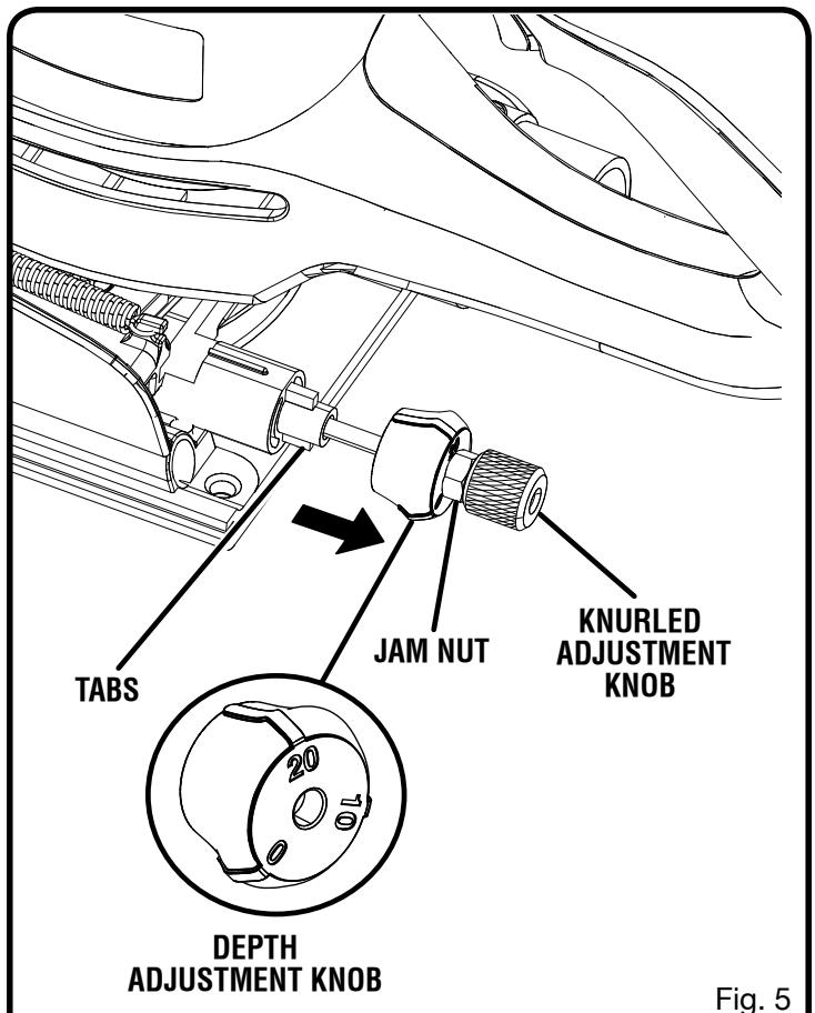
SETTING DEPTH OF CUT
See Figure 5.
Unplug the biscuit joiner.
- Select the correct depth of cut setting for the biscuit size you plan to use. To select depth of cut, pull the knurled adjustment knob and jam nut in the direction of the arrow in figure 5.
NOTE: The knob and jam nut are spring loaded. Pulling them in the direction of the arrow puts pressure on the spring and releases pressure from the depth adjustment knob.
- Rotate the depth adjustment knob until the desired slot setting aligns with the tabs on the rear base assembly.
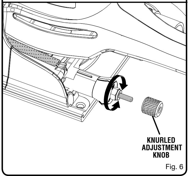
MAKING FINE ADJUSTMENTS
See Figure 6.
Make a test cut in a scrap piece of wood. Fit the correct size biscuit into the biscuit slot. The biscuit slot should be deep enough to allow slightly more than one-half of the biscuit into the slot. This extra room allows for proper alignment of the wood being joined.
If the biscuit slot is too deep or too shallow, fine adjustments to the depth setting can be made by loosening the knurled adjustment knob and making fine adjustments with the jam nut.
Unplug the biscuit joiner.
- Loosen the knurled adjustment knob. This knob is used as a lock nut only. Loosen by twisting it in the opposite direction away from the jam nut.
- Rotate the jam nut to the right for a more shallow cut, or to the left for a deeper cut.
Once desired depth of cut is reached, hold the jam nut so that it will not move out of adjustment. Next, tighten the knurled adjustment knob against jam nut.
- Recheck the depth setting by making a test cut in a scrap piece of wood. Also periodically check the depth setting for accuracy. Rotating the jam nut to the right will cut shallow biscuit slots. Rotating the jam nut to the left will cut deeper biscuit slots.
OPERATION
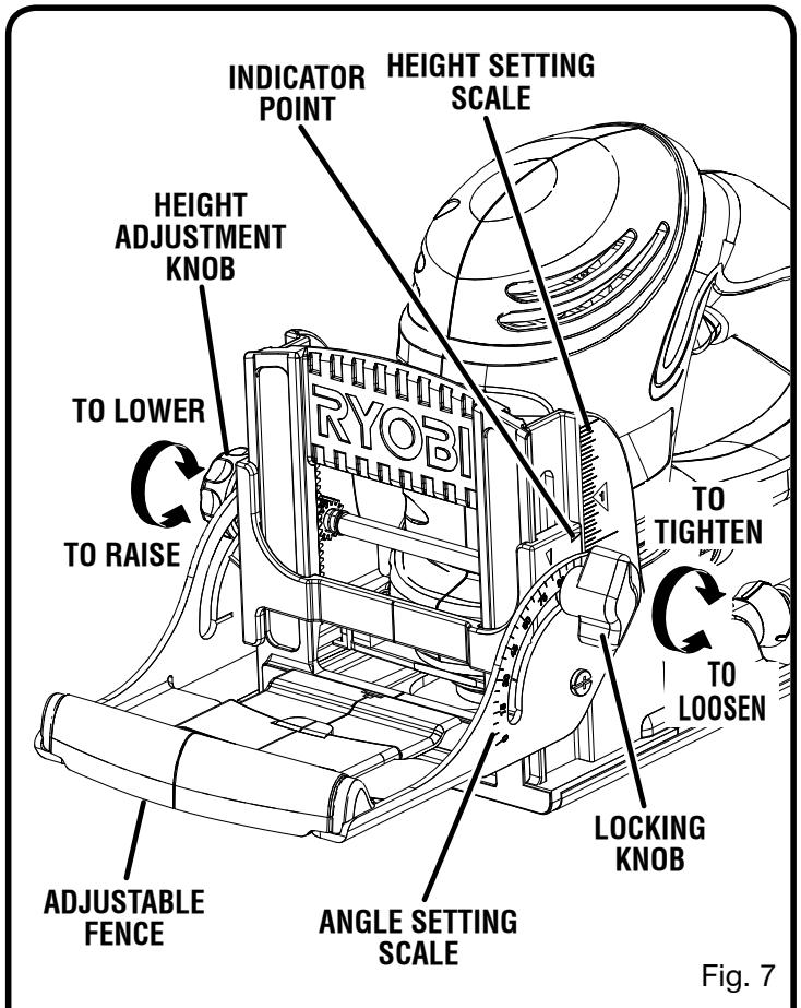
FENCE HEIGHT
The adjustable fence on the biscuit joiner can be moved up or down to adjust the position of the blade in relation to the top of the workpiece. A scale on each side of the fence indicates the height of the fence from the center of the blade. The fence can be positioned up to two inches from the center of the blade. However, the scale and indicator point can only be set up to 2 in. from the center of the blade. Scale marks are in increments of 1/16 in.
SETTING THE FENCE HEIGHT
See Figure 7.
Unplug the biscuit joiner.
Loosen the locking knob approximately one turn.
- Move the fence up or down by rotating the height adjustment knob until the indicator point is aligned with the desired dimension on the scale.
Tighten the locking knob securely.
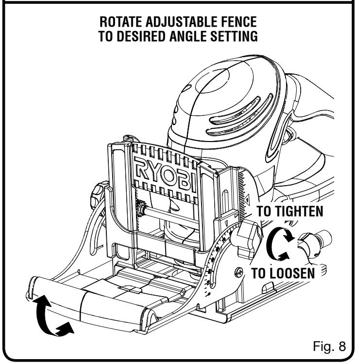
FENCE ANGLE
The adjustable fence on the biscuit joiner can be set at angles ranging from 0^ to 135^ , with accurate positive stops set in 45^ increments. A scale is located on each side of the adjustable fence for identifying these positive stop angles. Each stop reached when rotating the adjustable fence from one angle setting to another equals a 45^ positive stop angle change.
SETTING THE FENCE ANGLE
See Figure 8.
Unplug the biscuit joiner.
Loosen the locking knob approximately one turn.
Rotate the fence to the desired angle.
Tighten the locking knob securely.
OPERATION
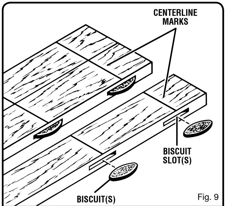
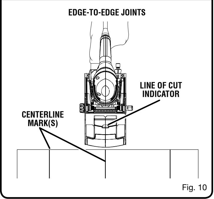
MAKING EDGE-TO-EDGE JOINTS
See Figures 9 - 10.
Edge-to-edge joinery is one of the most basic and easily-constructed joints.
Unplug the biscuit joiner.
Prepare the workpieces by laying them side by side on a workbench in the order in which they will be assembled.
Using a square, determine the location of each biscuit spline joint and mark the center of each joint by drawing a line across each workpiece.
NOTE: Mark the edges 2 in. from the ends of the workpieces. The joint will be stronger if you use multiple biscuits placed close together.
- Loosen the locking knob approximately one turn and set the fence angle at 90^ .
- Set the fence height at the desired dimension on the scale by rotating the height adjustment knob.
NOTE: The scale indicates the height of the fence from the center of the blade.
Tighten the locking knob securely.
- Select the correct depth of cut setting to match the biscuit size you are planning to use. Make a test cut in a scrap piece of wood from the same workpiece if possible.
- Clamp the workpiece securely so that it will not move during the cut.
Plug the biscuit joiner into the power supply and prepare to make the first cut. Grasp and hold the biscuit joiner securely with both hands.
- Place the fence against the board and align the indicator marks on the fence with the centerline mark(s) on the board.
Depress the switch trigger to turn on the biscuit joiner, then push it forward to extend the blade into the wood.
- When the base assembly bottoms out against the depth of cut adjustment knob setting, pull back, releasing pressure on the spring. The blade will retract from the biscuit slot.
Repeat this procedure for all desired biscuit slots.
Once all biscuit slots have been cut, place a biscuit in each joint and dry-assemble the workpiece. Make sure each joint lines up and fits.
Finally, disassemble the workpieces and place a bead of glue in each slot. Also, spread a bead of glue over the entire surface of the joint. Reinsert the biscuits and assemble the workpieces.
- Clamp workpieces together until the glue sets up.
OPERATION
BUTT JOINTS
A butt joint is made by mating the end grain of one board with the edge grain of another. The bonding of glue on this type of surface is poor. However, by using biscuits you can create a strong joint that gives a mortise-and-tenon effect.
MAKING BUTT JOINTS
See Figures 11 - 12.
Unplug the biscuit joiner.
- Place the two pieces of wood to be joined on a level workbench. Align them against each other in the arrangement in which they will be assembled.
Using a square, determine the location of each biscuit spline joint and mark the center of each joint by drawing a line across the edges of the two boards.
Loosen the locking knob and set the fence angle at 90^ .
- Set the fence height at the desired dimension on the scale by rotating the height adjustment knob.
NOTE: The scale indicates the height of the fence from the center of the blade.
Tighten the locking knob securely.
- Select the correct depth of cut setting to match the biscuit size you are planning to use. Make a test cut in a scrap piece of wood from the same workpiece if possible.
- Clamp the workpiece securely so that it will not move during the cut.
Plug the biscuit joiner into a power supply and prepare to make your first cut. Grasp and hold the biscuit joiner securely with both hands.
- Place the fence against the board and align the indicator marks on the fence with the centerline mark(s) on the board.
- Depress the switch trigger to turn on the biscuit joiner, then push it forward to extend the blade into the wood.
- When the base assembly bottoms out against the depth of cut adjustment knob setting, pull back to release pressure on the spring. The blade will retract from the biscuit slot.
Repeat this procedure for cutting the slot in the mating workpiece.
Once all biscuit slots have been cut, place a biscuit in each joint and dry-assemble the workpieces. Make sure each joint lines up and fits.
Finally, disassemble the workpieces and place a bead of glue in each slot. Also, spread a bead of glue over the entire surface of the joint. Reinsert the biscuits and assemble the workpieces as shown in figure 10.
- Clamp the workpieces together until the glue sets up.
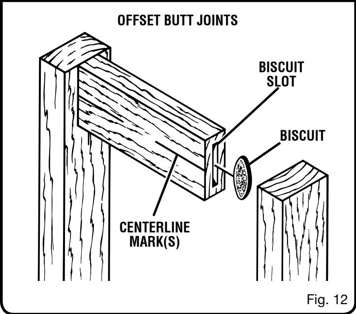
OFFSET BUTT JOINTS
See Figure 12.
The rails of a table or workbench are often offset from the front of the table legs. When offsets are required, it is necessary to cut the slots in the rails first, then readjust the fence to cut the slots in the legs.
Keeping this one exception in mind, the procedure for cutting offset butt joints is identical to the procedure for cutting butt joints.
For example, if a 1/4 in. offset is desired, you would mark the centerlines for cutting a butt joint as mentioned in the procedures for cutting butt joints, and cut the slots in the ends of the rails. Next you would raise the fence 1/4 in. to the desired offset and cut the slots in the legs.
OPERATION
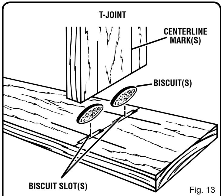
T- JOINTS
See Figure 13.
A T-joint is used when the end of a board is joined to the face of another board as shown in figure 12. Attaching shelves to bookcases and inner support braces to frames are typical applications. Actual cutting of a T-joint is as simple as any other cut. However, it is critical that you mark the centerlines, mark the intersection points for each slot, and cut each slot correctly.
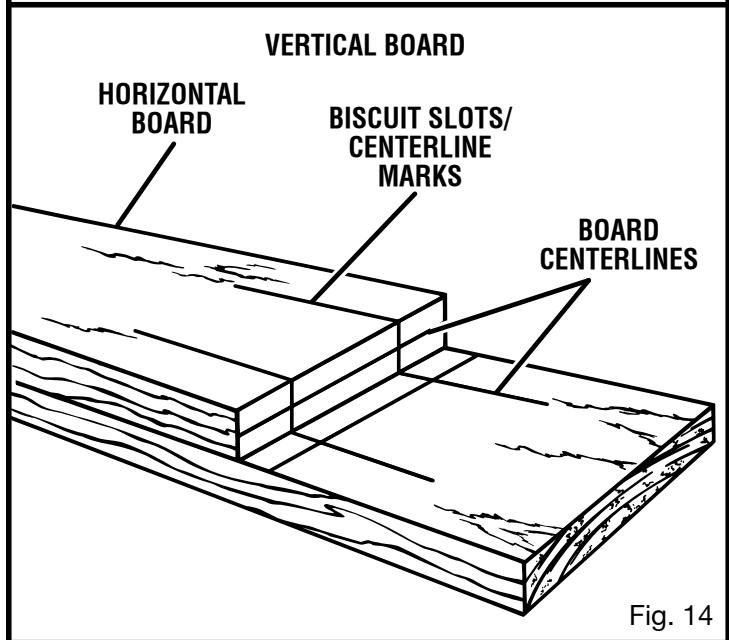
MAKING T- JOINTS
See Figures 14 - 15.
Unplug the biscuit joiner.
- Place the two pieces of wood to be joined on a level workbench. The inside face of the vertical board should be facing up.
Determine the location of each biscuit joint and mark the centerlines on each board. The centerlines for both boards must line up with each other. Measure carefully; these measurements must be accurate and precise.
NOTE: Measure twice and cut once. In addition to the centerlines lining up, the spacing of the biscuit slots from side-to-side must also match.
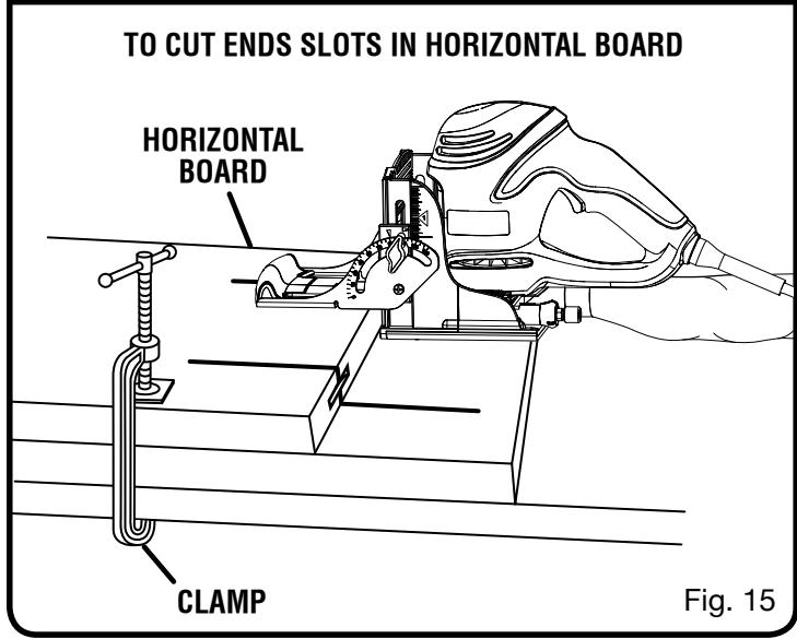
Plug the biscuit joiner into the power supply and cut slots in all boards that require end slots.
Follow the procedures explained in "Edge-To-Edge Joints."
Set the fence angle at 90^
Set the fence height at the desired dimension on the scale.
- Select the correct depth of cut setting for the biscuit size you plan to use.
- Clamp the workpiece securely, then cut each slot at the marked centerline intersection.
Next, you must adjust the fence on the biscuit joiner in order to cut slots into the face of the vertical board.
OPERATION
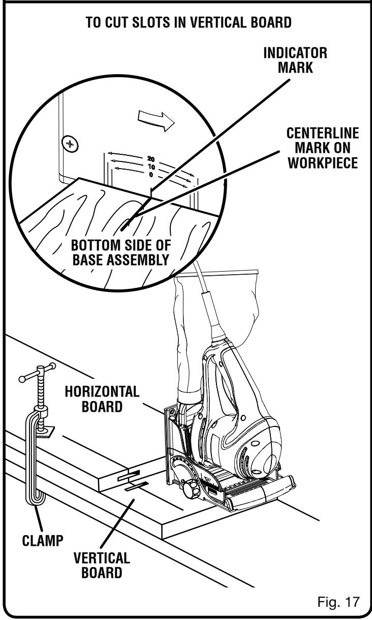
CUTTING VERTICAL BOARDS
See Figures 16 - 17.
Unplug the biscuit joiner.
Loosen the locking knob and set the fence angle at 0^
- Set the fence height at the desired dimension on the scale by rotating the height adjustment knob.
Retighten the locking knob.
- Select the correct depth of cut setting for the biscuit size you plan to use.
Clamp the workpiece securely.
Cut each slot at the marked centerline intersection.
- Place the biscuit joiner on a vertical board and align the indicator marks on the base assembly with the centerline on the vertical board.
- Place a straight piece of wood on the vertical board and securely clamp it flush against the base assembly. This piece of wood is used for a fence or guide. It must be square with the sides of the vertical board and parallel with the centerline.
Align the centerline on the bottom of the base assembly with marked intersection for biscuit slot.
Plug the biscuit joiner into the power supply and prepare to cut the slot.
Depress the switch trigger to turn on the biscuit joiner, then push it down to extend the blade into the wood.
- When the base assembly bottoms out against the depth of cut adjustment knob setting, pull back, releasing pressure on the spring. The blade will retract from the biscuit slot.
Repeat this procedure for cutting all required slots in vertical boards.
Once all slots have been cut, place a biscuit in each joint and dry-assemble the workpieces. Make sure each joint lines up and fits.
Finally, disassemble the workpieces and place a bead of glue in each slot. Also, spread a bead of glue over the entire surface of the joint. Reinsert the biscuits and assemble the workpieces.
- Clamp the workpieces together until the glue sets up.
OPERATION
MITER JOINTS
See Figures 18 - 21.
There are two types of miter joints that can be made using biscuits: flat mitters and edge mitters. Flat mitters are used when making picture frames. Edge mitters are used when making boxes or things where you don't want to show the end grain of the wood.
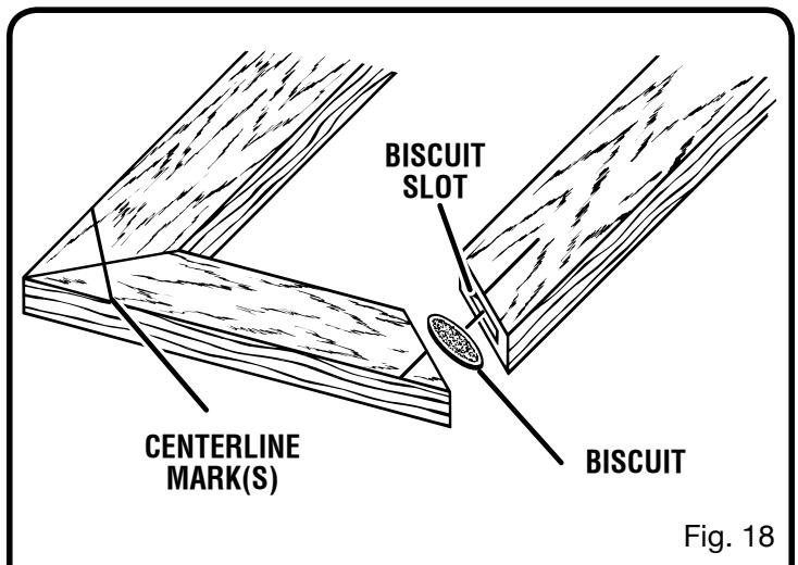
MAKING FLAT MITER JOINTS
See Figure 18.
Unplug the biscuit joiner.
Place the pieces of wood to be joined on a level workbench.
Using a combination square, draw a line through the center of each joint perpendicular to the mitered edges.
- Set the fence angle at 90^ , set the fence height at the desired dimension on the scale, select the correct depth of cut setting for the biscuit size you plan to use, and clamp the workpiece securely.
Align the indicator mark on the fence with the centerline on the workpiece.
Plug the biscuit joiner into the power supply and prepare to cut the slot.
Depress the switch trigger to turn on the biscuit joiner, then push it forward to extend the blade into the wood.
- When the base assembly bottoms out against the depth of cut adjustment knob setting, pull back, releasing pressure on the spring. The blade will retract from the biscuit slot.
Repeat this procedure for cutting the mating slot and all required miter joint slots.
- Once all slots have been cut, place a biscuit in each joint and dry assemble the workpieces. Make sure each joint lines up and fits.
Finally, disassemble the workpieces and place a bead of glue in each slot. Also, spread a bead of glue over the entire surface of the joint. Reinsert the biscuits and assemble the workpieces.
- Clamp the workpieces together until the glue sets up.
OPERATION
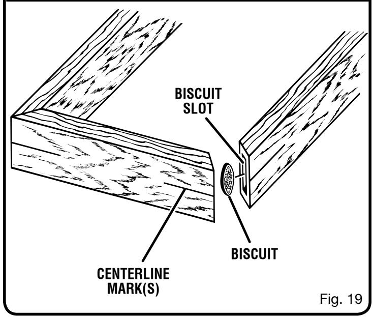
MAKING EDGE MITER JOINTS
See Figures 19 - 21.
Unplug the biscuit joiner.
- Place the pieces of wood to be joined on a level workbench.
■ Mark the centerline of the joint on each board.
- When making edge miter joints with workpieces that have different thicknesses, clamp the pieces securely to a workbench with the long sides up. This will assure that the outside surfaces will match.
Loosen the locking knob and set the fence angle at 135^ .
- Set the fence height at the desired dimension on the scale by rotating the height adjustment knob.
Tighten the locking knob securely.
- Place the biscuit joiner on the workpiece with the adjustable fence resting on the long side of workpiece. The base or vertical fence should be against the mitered edge of the workpiece.
- Recheck the fence height setting to make sure it will not cut through the workpiece.
- Align the indicator mark on the fence with the centerline on the workpiece. Make sure the base or vertical fence is pressed flat against the mitered edge of the workpiece.
Plug the biscuit joiner into the power supply and prepare to cut the slot.
Depress the switch trigger to turn on the biscuit joiner, then push it forward to extend the blade into the wood.
- When the base assembly bottoms out against the depth of cut adjustment knob setting, pull back, releasing pressure on the spring. The blade will retract from the biscuit slot.
Repeat this procedure for cutting the mating slot and all required miter joint slots.
Once all slots have been cut, place a biscuit in each joint and dry-assemble the workpieces. Make sure each joint lines up and fits.
Finally, disassemble workpieces and place a bead of glue in each slot. Also, spread a bead of glue over the entire surface of the joint. Reinsert the biscuits and assemble workpieces.
Clamp workpieces together until the glue sets up.
If the workpieces are of the same thickness, clamp them securely to a workbench with the short sides up. Set the fence angle at 45^ . Place the biscuit joiner on the workpiece with the adjustable fence resting on the short side of the workpiece and the base or vertical fence against the mitered edge of the workpiece. Follow steps above to cut required slots.
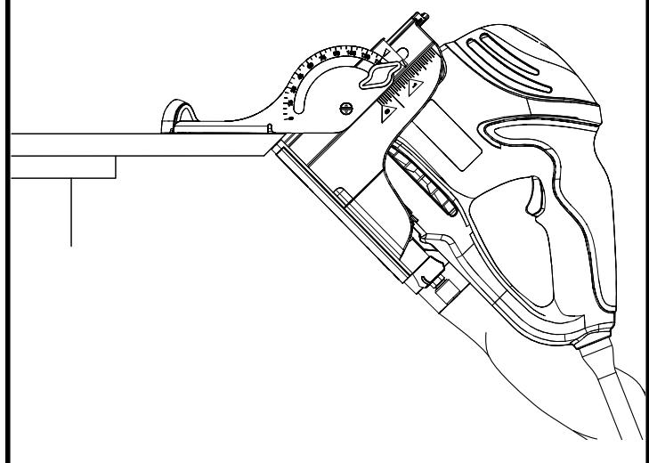
CUTTING EDGE MITER SLOT FROM LONG SIDE OF WORKPIECE
Fig. 20
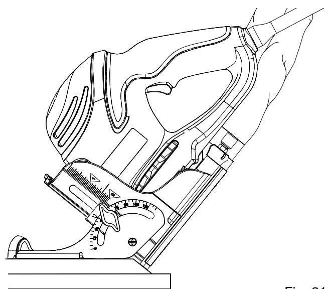
CUTTING EDGE MITER SLOT FROM SHORT SIDE OF WORKPIECE
Fig. 21
NOTE: Before cutting slots, make sure the blade will not cut through the workpiece and that both the vertical and horizontal fences are pressed flat against the mitered edge and face of the workpiece.

WARNING:
When servicing, use only identical Ryobi replacement parts. Use of any other parts may create a hazard or cause product damage.

WARNING:
Always wear safety goggles or safety glasses with side shields during power tool operation or when blowing dust. If operation is dusty, also wear a dust mask.
GENERAL MAINTENANCE
Avoid using solvents when cleaning plastic parts. Most plastics are susceptible to damage from various types of commercial solvents and may be damaged by their use. Use clean cloths to remove dirt, dust, oil, grease, etc.

WARNING:
Do not at any time let brake fluids, gasoline, petroleum-based products, penetrating oils, etc., come in contact with plastic parts. Chemicals can damage, weaken or destroy plastic which may result in serious personal injury.
Electric tools used on fiberglass material, wallboard, spackling compounds, or plaster are subject to accelerated wear and possible premature failure because the fiberglass chips and grindings are highly abrasive to bearings, brushes, commutators, etc. Consequently, we do not recommended using this tool for extended work on these types of materials. However, if you do work with any of these materials, it is extremely important to clean the tool using compressed air.
LUBRICATION
All of the bearings in this tool are lubricated with a sufficient amount of high grade lubricant for the life of the unit under normal operating conditions. Therefore, no further lubrication is required.
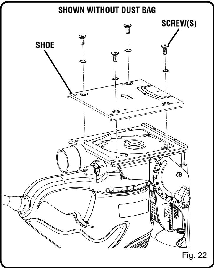
REPLACING THE BLADE
See Figures 22 - 24.
After extended use, the blade on your biscuit joiner may become dull and need replacing. If you accidentally hit a nail or other blunt object, it will break the carbide tips, which will require replacing the blade.
Unplug the biscuit joiner.
Remove the dust bag.
Place the biscuit joiner upside down on a workbench.
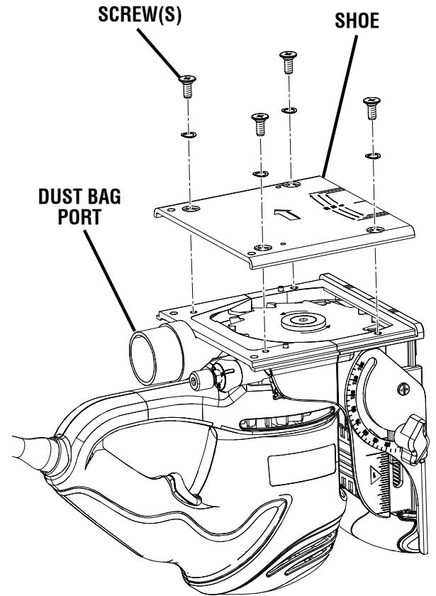
- With a screwdriver, remove the four screws and washers that connect the shoe to the front and rear assemblies. Remove the shoe.
MAINTENANCE
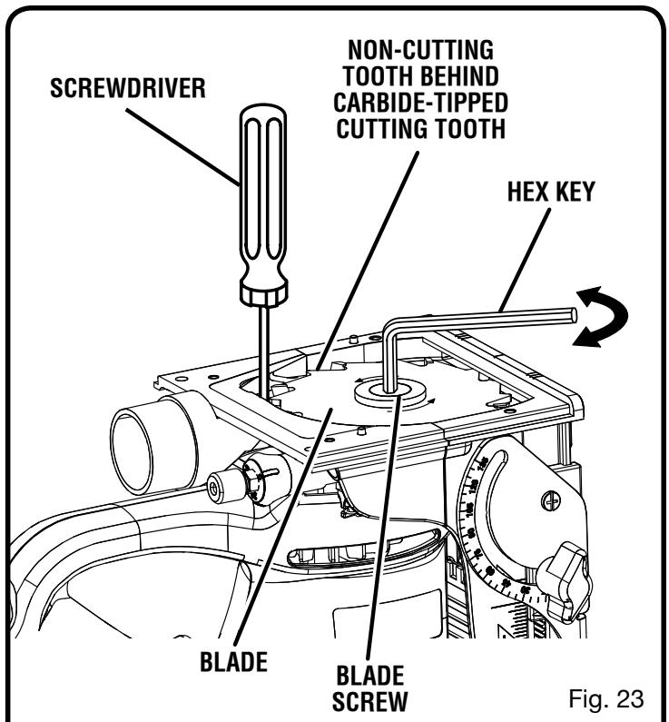
- Place a screwdriver in the hole provided in the bearing plate.
- Place one of the non-cutting teeth located behind each carbide-tipped cutting tooth against the screwdriver or pin and lock the blade to prevent it from rotating. DO NOT lock the blade against one of the cutting teeth. Carbide tips will break.
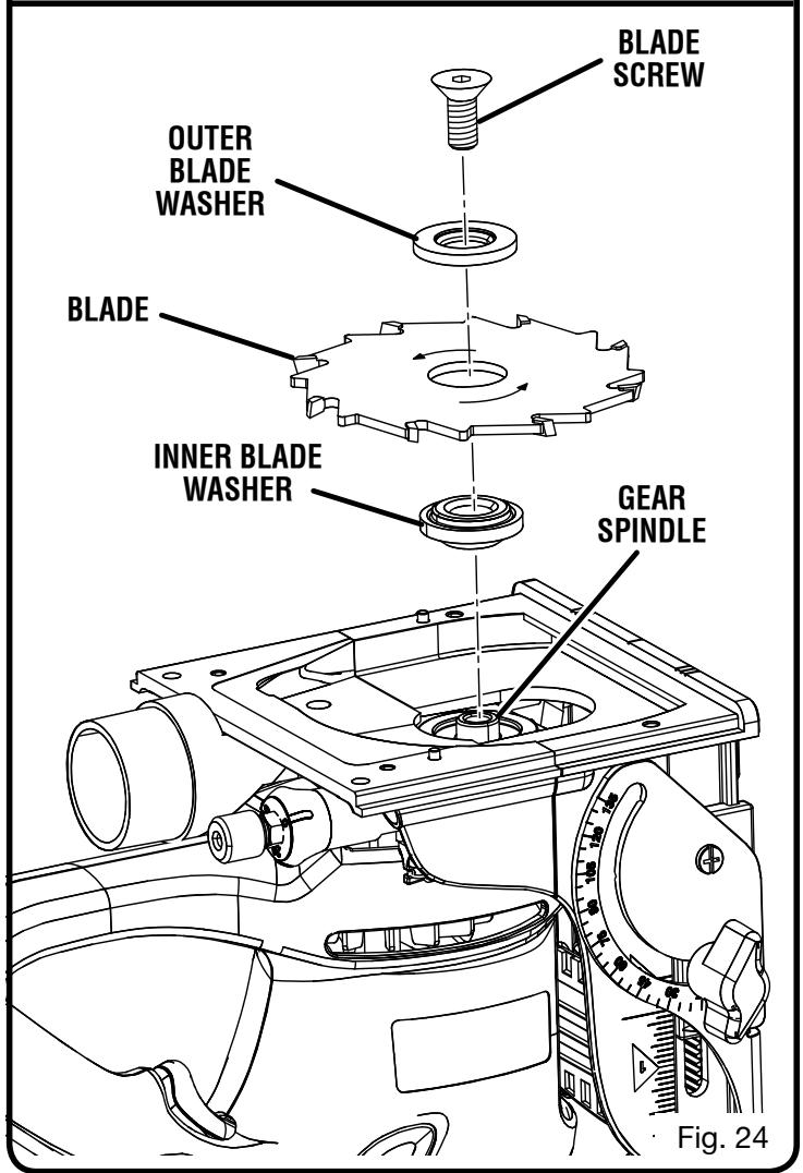
Using a 3/16 in. hex key, remove the blade screw.
NOTE: Turn the blade screw counterclockwise to remove the blade.
- Remove the outer blade washer, blade and inner blade washer.
- Clean wood particles and resin from the blade washers, dust bag area, base assembly, and all surrounding parts.
Place the inner blade washer on the gear spindle. - Place the new blade onto the shoulder of the blade washer and secure with the outer blade washer and the blade screw.
NOTE: The blade screw fits into the cupped side of the outer blade washer.
NOTE: The blade teeth point toward the right of the tool when held in normal operating position. The direction of rotation is marked on the joiner blade. An arrow on the bottom of the front base assembly also indicates direction of rotation.
- Place a screwdriver or pin in one of the two holes provided in the bearing plate and lock the blade to prevent it from rotating.
- Turn the blade screw clockwise and tighten securely with the hex key.
Replace the shoe. - Replace the washers and screws and tighten securely with a screwdriver.
Replace the dust bag.
CLEANING THE BASE ASSEMBLY AND DUST PATH
See Figures 25 - 27.
After extended use, wood particles and resin may build up inside the base assembly of your biscuit joiner and clog the path for wood particles going into dust bag. Wood particles packing up in this area not only defeats the dustless feature of your biscuit joiner, it also makes cutting biscuit slots more difficult.
Unplug the biscuit joiner.
Remove the dust bag.
Place the biscuit joiner upside down on a workbench.
Using a screwdriver, remove the four screws and washers securing the shoe. Remove the shoe.
Remove the blade. See "Replacing the Blade."
- With the blade removed, place the biscuit joiner right side up. Using a pair of needle nose pliers, stretch and release the springs from the tabs on the bearing plate.
SHOWN WITHOUT DUST BAG
Fig. 25
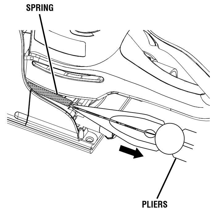
Fig. 26
MAINTENANCE
Using a screwdriver, remove the two screws that connect the front and rear base assemblies.
- Carefully separate the front base assembly from the rear base assembly. Remove the front base assembly.
NOTE: These pieces are tightly joined. It may be helpful to use a mallet to lightly tap the area where the assemblies meet.
Remove the rear base assembly.
- With the assemblies separated, clean wood particles and resin from the blade area, dust bag port, front and rear assemblies and all surrounding areas.
- Apply a thin coat of general purpose grease in slots or tracks on the bearing plate where the base slides.
Replace the rear base assembly.
- Replace the front base assembly. Replace and tighten the screws that connect the front and rear base assemblies.
Replace the springs.
Reinstall or replace the blade.
Secure the shoe with the washers and screws.
Replace the dust bag.
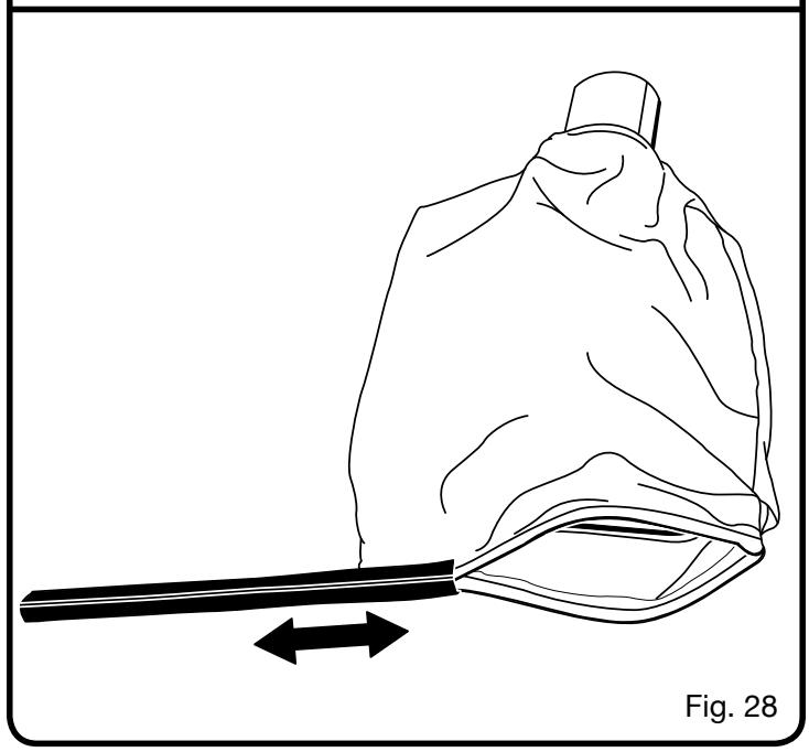
CLEANING THE DUST BAG
See Figure 28.
Unplug the biscuit joiner.
Remove the dust bag.
Slide the clip off the end of the dust bag.
Thoroughly clean the dust bag by shaking out all debris.
Replace the clip.
Replace the dust bag.
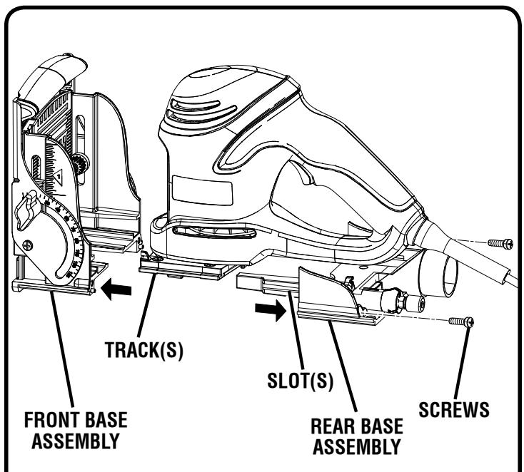
Fig. 27
ACCESSIONS
The following recommended accessories are currently available at retail stores:
Biscuits 100 pieces Size 0
Biscuits 100 pieces Size 10
Biscuits 100 pieces Size 20
■ Biscuit Assortment 400 pieces total
Size 0 .100 pieces
Size 10. 100 pieces
Size 20 200 pieces

WARNING:
Current attachments and accessories available for use with this tool are listed above. Do not use any attachments or accessories not recommended by the manufacturer of this tool. The use of attachments or accessories not recommended can result in serious personal injury.
TROUBLESHOOTING
PROBLEM
SOLUTION
- Biscuits do not fit the slots. Biscuits not fitting slots may also cause misalignment of the boards being joined.
A. Biscuit slots are too deep or too shallow. Make fine adjustments to depth setting. See “MAKING FINE ADJUSTMENTS”.
B. Biscuit thickness may be out of tolerance. Compress biscuits in a vise if they are too thick.
C. Check to see if biscuits are the correct size for the size slots that have been cut: #0, #10, or #20.
D. Check to see if biscuits have gotten wet and have swelled.
- Wood particles begin to back up on the front of the unit.
A. The dust collection system is not functioning properly. The dust bag may be full. Empty the dust bag often. See "INSTALLING/REMOVING DUST BAG".
B. The dust port may be clogged, preventing wood particles from being drawn into the dust bag. Remove the front and rear base assemblies and clean blade, bearing plate, base assembly slots, and surrounding areas. See “CLEANING THE BASE ASSEMBLY AND DUST PATH”.
- Blade becomes difficult to push in when cutting slots. Blade does not retract properly when cutting slots.
A. Wood particles and resin have built up on base assembly slots and surrounding areas. Remove front and rear base assemblies and clean blade, bearing plate, base assembly slots and surrounding areas. Apply a thin coat of general purpose grease in slots or on bearing plate where base slides. See “CLEANING THE BASE ASSEMBLY AND DUST PATH”.
- Cutting performance is poor and there is a loss of power or stalling of motor when cutting slots.
A. Blade is dull. Replace the blade. See "REPLACING THE BLADE".
B. Resin has built up on the blade. Remove the blade and clean blade with gum and pitch remover. See "REPLACING THE BLADE".
NOTES
- SERVICE
Now that you have purchased your tool, should a need ever exist for repair parts or service, simply contact your nearest Ryobi Authorized Service Center. Be sure to provide all pertinent facts when you call or visit. Please call 1-800-525-2579 for your nearest Ryobi Authorized Service Center. You can also check our web site at www.ryobitools.com for a complete list of Authorized Service Centers.
- MODEL NO. AND SERIAL NO.
The model number of this tool will be found on a plate attached to the motor housing. Please record the model number and serial number in the space provided below.
HOW TO ORDER REPAIR PARTS
When ordering repair parts, always give the following information:
- MODEL NUMBER
JM82
- SERIAL NUMBER
- TABLE OF CONTENTS
- INTRODUCTION
- GENERAL SAFETY RULES
- WARNING:
- SAVE THESE INSTRUCTIONS
- WORK AREA
- ELECTRICAL SAFETY
- PERSONAL SAFETY
- TOOL USE AND CARE
- SERVICE
- SPECIFIC SAFETY RULES
- SYMBOLS
- ELECTRICAL
- DOUBLE INSULATION
- ELECTRICAL CONNECTION
- EXTENSION CORDS
- FEATURES
- PRODUCT SPECIFICATIONS
- KNOW YOUR BISCUIT JOINER
- SWITCH TRIGGER
- CARBIDE-TIPPED BLADE
- NON-SKID SURFACE
- DEPTH ADJUSTMENT KNOB
- HEIGHT SETTING SCALE
- HEIGHT ADJUSTMENT KNOB
- LOCKING KNOB
- ANGLE SETTING SCALE
- DUAL GRIP HANDLE
- DUST COLLECTION
- LINE OF CUT INDICATOR
- ADJUSTABLE FENCE
- BISCUITS
- UNPACKING
- PACKING LIST
- INSTALLING/REMOVING THE DUST BAG
- ATTACHING THE BISCUIT JOINER TO A VACUUM
- OPERATION
- APPLICATIONS
- SPLINE JOINERY
- TURING ON/OFF THE BISCUIT JOINER
- DEPTH OF CUT
- SETTING DEPTH OF CUT
- MAKING FINE ADJUSTMENTS
- FENCE HEIGHT
- SETTING THE FENCE HEIGHT
- FENCE ANGLE
- SETTING THE FENCE ANGLE
- MAKING EDGE-TO-EDGE JOINTS
- BUTT JOINTS
- MAKING BUTT JOINTS
- OFFSET BUTT JOINTS
- T- JOINTS
- MAKING T- JOINTS
- CUTTING VERTICAL BOARDS
- MITER JOINTS
- MAKING FLAT MITER JOINTS
- MAKING EDGE MITER JOINTS
- GENERAL MAINTENANCE
- LUBRICATION
- REPLACING THE BLADE
- MAINTENANCE
- CLEANING THE BASE ASSEMBLY AND DUST PATH
- See Figures 25 - 27.
- CLEANING THE DUST BAG
- ACCESSIONS
- TROUBLESHOOTING
- PROBLEM
- SOLUTION
- NOTES
- - SERVICE
- - MODEL NO. AND SERIAL NO.
- HOW TO ORDER REPAIR PARTS
Brand : RYOBI
Model : JM82K
Category : Power Tools