95-7399 - Car Radio Metra - Free user manual and instructions
Find the device manual for free 95-7399 Metra in PDF.

User questions about 95-7399 Metra
0 question about this device. Answer the ones you know or ask your own.
Ask a new question about this device
Download the instructions for your Car Radio in PDF format for free! Find your manual 95-7399 - Metra and take your electronic device back in hand. On this page are published all the documents necessary for the use of your device. 95-7399 by Metra.
USER MANUAL 95-7399 Metra
natural_image
Interior view of a car dashboard with air conditioners and a digital display (no visible text or symbols)Hyundai Elantra 2019-2020
Visit MetraOnline.com for more detailed information about the product and up-to-date vehicle specific applications
KIT FEATURES
• ISO DDIN radio provision
- Painted scratch resistant matte black
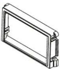
KIT COMPONENTS
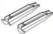
• A) Radio trim panel • B) Radio brackets • C) Blank panel • D) Blank panel clip legs (2) • E) #6 x 3/8" Phillips screws (2)
• F) #8 x 1/4" Phillips screws (4) • G) Panel clips (2)
AB
natural_image
Technical line drawing of a rectangular electronic component or enclosure (no text or symbols)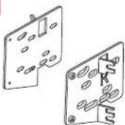

D
E

F

G
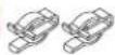
TABLE OF CONTENTS
Dash Disassembly ....2 Kit Assembly ....3
WIRING & ANTENNA CONNECTIONS (sold separately)
Wiring Harness: 70-7304 (w/o 7-inch display radio)
• 70-7306 (with 7-inch display radio)
Antenna Adapter: N/A (w/o 7-inch display radio)
• 40-K111 (with 7-inch display radio)
Please visit metraonline.com or axxessinterfaces.com for other harness and interface options.
TOOLS REQUIRED
- Panel removal tool • Phillips screwdriver
- Socket wrench
Attention! With the key out of the ignition, disconnect the negative battery terminal before installing this product. Ensure that all installation connections are secure before cycling the ignition to test this product.
DASH DISASSEMBLY
- Open the passenger front door, then unclip and remove the trim panel from the side of dashboard. Remove the (1) Phillips screw securing the silver trim panel. (Figure A)
- Unclip and remove the silver trim panel that runs along the dashboard from under the radio, and above the glovebox (Figure B)
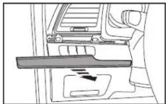
- Open the driver's door, then unclip and remove the trim panel from the side of the dashboard. Remove the (1) Phillips screw securing the silver trim panel. (Figure C)

natural_image
Diagram of a car's side profile showing airflow or exhaust flow direction (no text or symbols)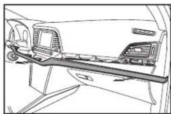
natural_image
Line drawing of a car interior showing the rear wheel, dashboard, and seat (no text or symbols)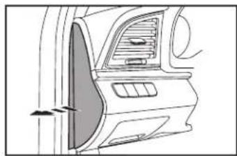
natural_image
Side view of a car's front and side panels showing airflow or exhaust flow (no text or symbols)- Unclip and remove the silver trim panel from under the driver's side A/C vent. (Figure D)
- Unclip the trim panel above the steering column, and then unclip and remove the entire panel surrounding the instrument cluster. Note, these two panels are one assembly. (Figure E)
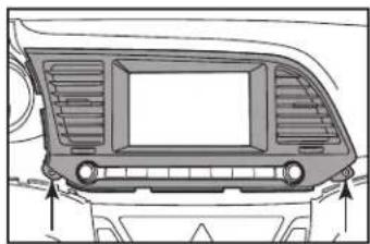
- Remove the (2) Phillips screws securing the radio trim panel, then unclip and remove the panel. (Figure F)
- Remove the (4) Phillips screws securing the radio and then remove.
Continue to Kit Assembly
natural_image
Interior view of a vehicle showing the dashboard and seat area with a hand gesture (no text or symbols)(Figure D)(Figure A)

natural_image
Diagram of a car interior showing dashboard and steering wheel (no text or labels)(Figure E)(Figure B)
natural_image
Top-down technical diagram of a car's front dashboard and rear seats (no text or symbols)(Figure F)(Figure C)
KIT ASSEMBLY
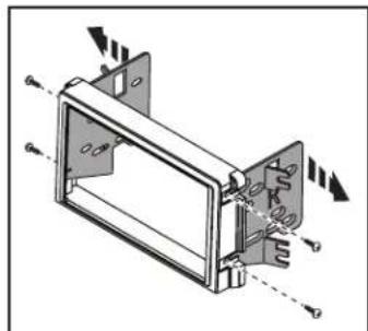
- Attach the radio brackets to the radio trim panel using (4) #8 x 1/4" Phillips screws supplied. (Figure A)
- Slide the radio into the completed assembly, and then secure it to the assembly using screws supplied with the radio. (Figure B)
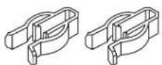
- Attach the blank panel clip legs to the blank panel using (2) #6 X 3/8" Phillips screws supplied. (Figure C)
- Attach the panel clips to the panel legs. (Figure D)
natural_image
Mechanical assembly diagram showing a frame with internal components and directional arrows (no text or symbols)(Figure A)

text_image
Technical diagram of a device with labeled ports and directional arrows indicating movement or assembly.(Figure B)
- Snap the blank panel into the factory trim panel. (Figure E)
- Locate the factory wiring harness and antenna connector in the dash, and complete all necessary connections to the radio. Metra recommends using the proper mating adapter from Metra and/or AXXESS. Re-connect the negative battery terminal and test the radio for proper operation.
- Reassemble the dash in reverse order of disassembly.

natural_image
Technical line drawing of a mechanical component with multiple cylindrical parts and dashed alignment lines (no text or symbols)(Figure D)

natural_image
Technical line drawing of a mechanical component with two mounting holes (no text or symbols)(Figure D)

natural_image
Technical line drawing of a mechanical assembly with no visible text or symbols(Figure E)
Having difficulties? We're here to help.

our Tech Support line at:
386-257-1187

mail at:
techsupport@metra-autosound.com
Tech Support Hours (Eastern Standard Time)
Monday - Friday: 9:00 AM - 7:00 PM
Saturday: 10:00 AM - 7:00 PM
Sunday: 10:00 AM - 4:00 PM

KNOWLEDGE IS POWER
Enhance your installation and fabrication skills b enselling in the most recognized and respected
mobile electronics school in our industry.
Log onto www.installerinstitute.edu or call
366-672-5171 for more information and take steps toward a better tomorrow.

Metra recommends MECP certified technicians

natural_image
Interior view of a car dashboard with air condition meters and a digital display (no visible text or symbols)
natural_image
Black plastic automotive box assembly with mounting brackets and front panel (no text or symbols)HARDWARE INCLUDED


Hyundai Elantra 2019-2020
Visit MetraOnline.com for more detailed information about the product and up-to-date vehicle specific applications.

ISO DDIN radio provision
Painted scratch resistant matte black
KIT COMPONENTS
- Radio trim panel
- Radio brackets
- Blank panel
- Blank panel clip legs (2)
-
6 x 3/8" Phillips screws (2)
-
8 x 1/4" Phillips screws (4)
- Panel clips (2)
WIRING & ANTENNA CONNECTIONS
(sold separately)
Wiring Harness: 70-7304 (w/o 7-inch display radio)
- 70-7306 (with 7-inch display radio)
Antenna Adapter: N/A (w/o 7-inch display radio)
• 40-KI11 (with 7-inch display radio)
Please visit metraonline.com or axxessinterfaces.com for other harness and interface options.
SALES 386-257-2956