DS-LEDTK-6S - Wall mount for screen Peerless-AV - Free user manual and instructions
Find the device manual for free DS-LEDTK-6S Peerless-AV in PDF.


| Brand | Peerless-AV |
| Model | DS-LEDTK-6S |
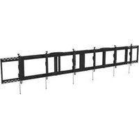
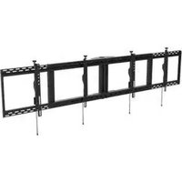
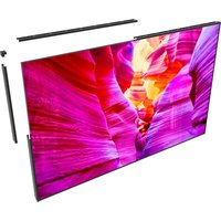
| Product Type | Wall Mount Trim Kit for LED Video Walls |
| Compatible Wall Material | Plywood (minimum 1/2" thick with 2"x4" studs) |
| Installation Hardware | Wood screws (#14-10 x 1.75") and togglers included |
| Minimum Mounting Depth | 1.75 inches (44 mm) |
| Trim Kit Options | Solid or perforated covers |
| Included Accessories | Cutting jigs, spacers, wall brackets, allen wrench, vinyl stickers |
| Special Features | Adjustable spacers for flush fit, supports Unilumin UpanelS bump-outs |
| Safety | Designed for plywood walls; do not exceed load capacity; use assistant for lifting |
| Intended Use | Indoor only |
| Warranty | Refer to peerless-av.com/warranty |
| Customer Service | 1-800-865-2112 or tech@peerlessmounts.com |
Frequently Asked Questions - DS-LEDTK-6S Peerless-AV
User questions about DS-LEDTK-6S Peerless-AV
0 question about this device. Answer the ones you know or ask your own.
Ask a new question about this device
Download the instructions for your Wall mount for screen in PDF format for free! Find your manual DS-LEDTK-6S - Peerless-AV and take your electronic device back in hand. On this page are published all the documents necessary for the use of your device. DS-LEDTK-6S by Peerless-AV.
USER MANUAL DS-LEDTK-6S Peerless-AV
natural_image
Isometric line drawing of a rectangular panel with a diagonal edge and side notches (no text or symbols)WARNING
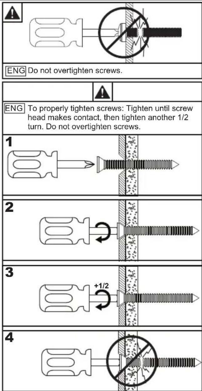
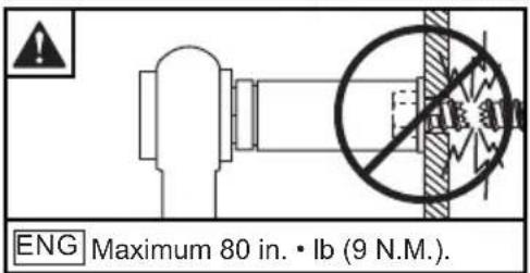
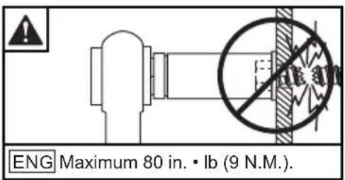
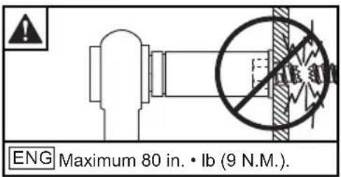
ENG - This product is designed to be installed on plywood walls. Hardware is included for plywood installation. This product is designed to be installed on flat, unobstructed, vertical walls. Do not install on curved or angled walls. Before installing make sure the supporting surface will support the combined load of the equipment and hardware. Screws must be tightly secured. Do not overtighten screws or damage can occur and product may fail. Never exceed the Maximum Load Capacity. Always use an assistant or mechanical lifting equipment to safely lift and position equipment. This product is intended for indoor use only. Use of this product outdoors could lead to product failure or personal injury. Be careful not to pinch fingers when operating the mount. For support please call customer care at 1-800-865-2112.
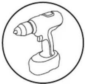
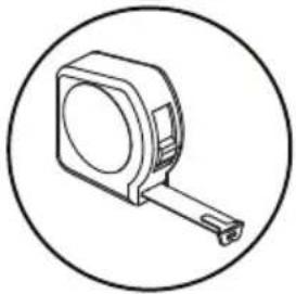
ENG Tools Needed for Assembly.
natural_image
Simple line drawing of a mechanical component inside a circle (no text or symbols)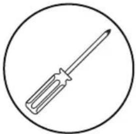
natural_image
Line drawing of a screwdriver inside a circle (no text or symbols)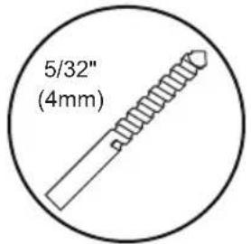
natural_image
Line drawing of a handheld electric drill (no text or symbols)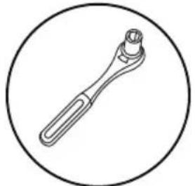
natural_image
Line drawing of a wrench inside a circle (no text or symbols)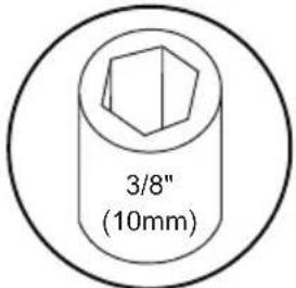
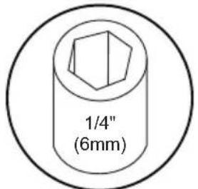
natural_image
Line drawing of a measuring tape inside a circle (no text or symbols)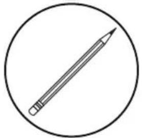
natural_image
Simple line drawing of a pencil inside a circle (no text or symbols)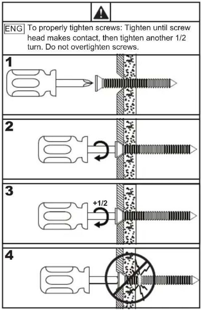
ENG Parts (Before beginning, make sure you have all parts shown below).
Parts List
Description Part #
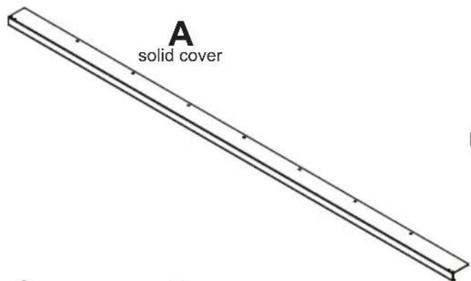
| A solid cover - | |
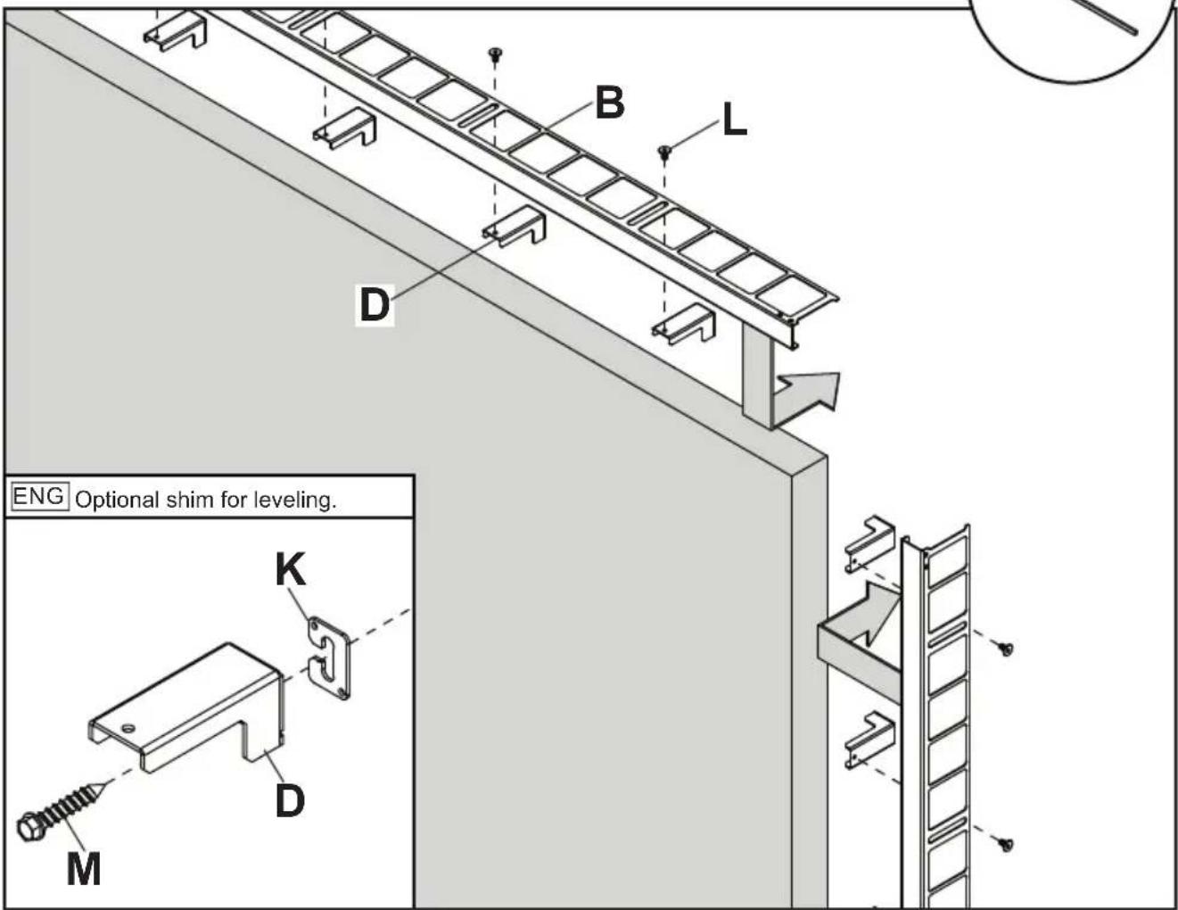
| B perforated cover - | |
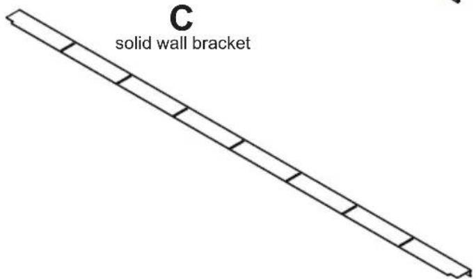
| C solid wall bracket - | |
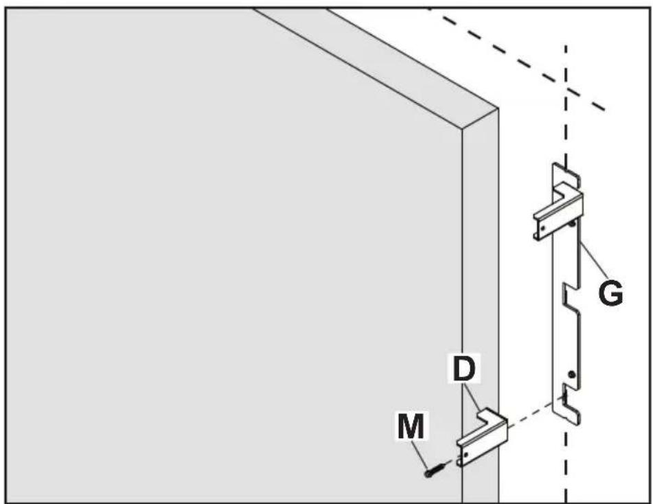
| D wall-side bracket 147-1859 | |
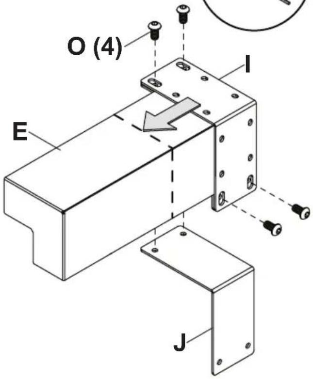
| E corner cover assembly 147-1876 | |
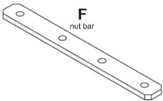
| F nut bar 147-T1881 | |
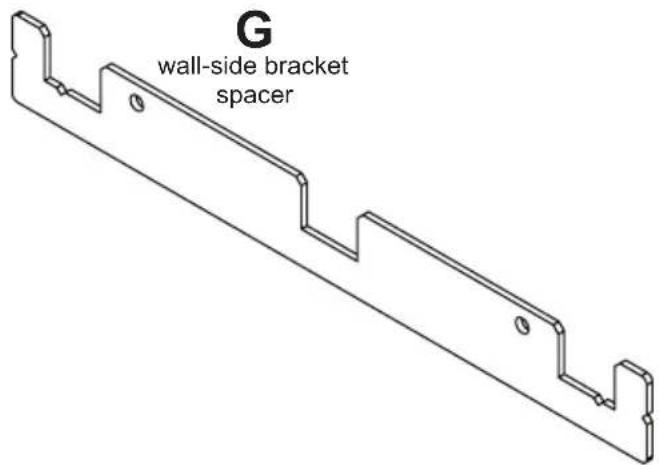
| G wall-side bracket spacer 147-T1879 | |
| H solid wall bracket spacer 147-T1880 | |
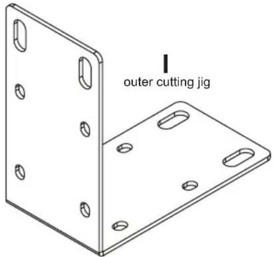
| I outer cutting jig 147-T1882 | |
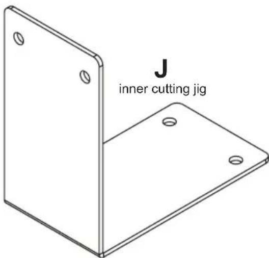
| J inner cutting jig 147-T1883 | |
| K wall plate shim 147-1891 | |
| L 1/4-20 x 25mm screw | 521-0710 |
| M #14-10 x 1.75 wood screw | 521-1688 |
| N M3 x 8mm phillips | 521-0711 |
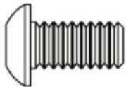
| O 1/4-20 x 1/2 btn skt scr | 520-1169 |
| P vinyl sticker | 580-0535 |
| Q toggler | 590-1093 |
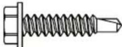
| R #8-18 X 3/4" self drilling screw | 521-0714 |
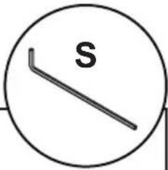
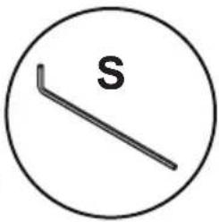
| S 4mm allen wrench | 560-9646 |
| T 1/4-20 x 12mm screw | 520-2325 |
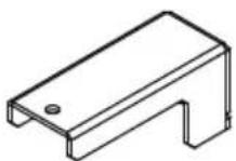
D
wall-side bracket
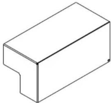
E
corner cover
natural_image
Isometric line drawing of a rectangular block with a notch (no text or symbols)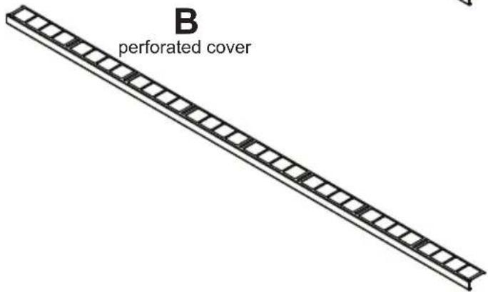
O
1/4-20 × 1/2
R
8-18 X 3/4"
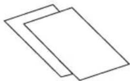
P
vinyl sticker
natural_image
Two overlapping rectangular shapes with no text or symbolsS (1)
4mm allen
wrench
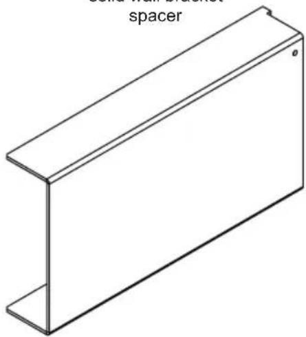
H
solid wall bracket
spacer
natural_image
Isometric line drawing of a rectangular I-beam with no text or symbolsK
wall plate shim

natural_image
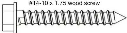
Technical line drawing of a mechanical bracket component (no text or symbols)M
14-10 x 1.75 wood screw
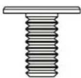
T
1/4-20 x 12mm 1/4-203x25mm
N

L
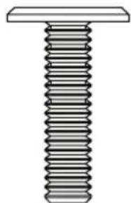
natural_image
Simple line drawing of a bolt with no text or symbolsQ
toggler
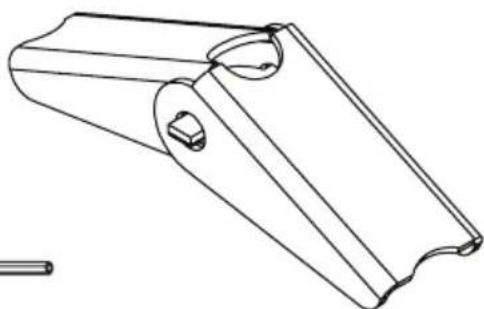
natural_image
Technical line drawing of a mechanical bracket or clamp component (no text or symbols)1

Follow steps for solid or perforated trim kits.
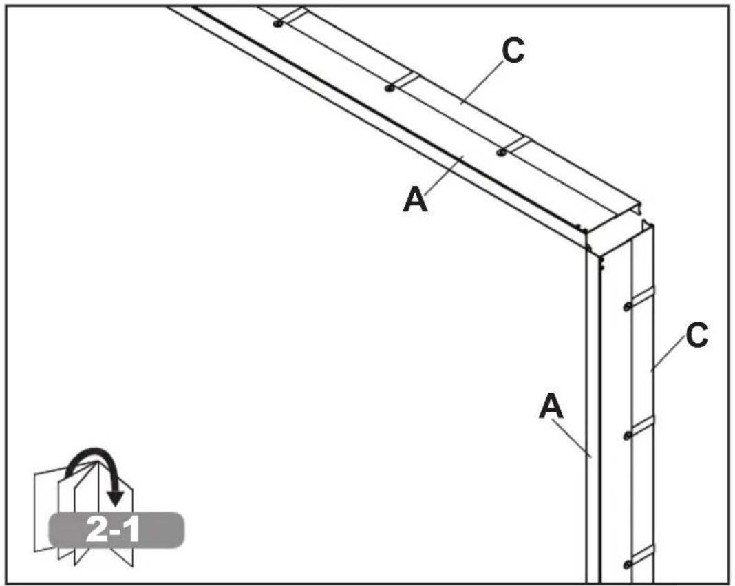
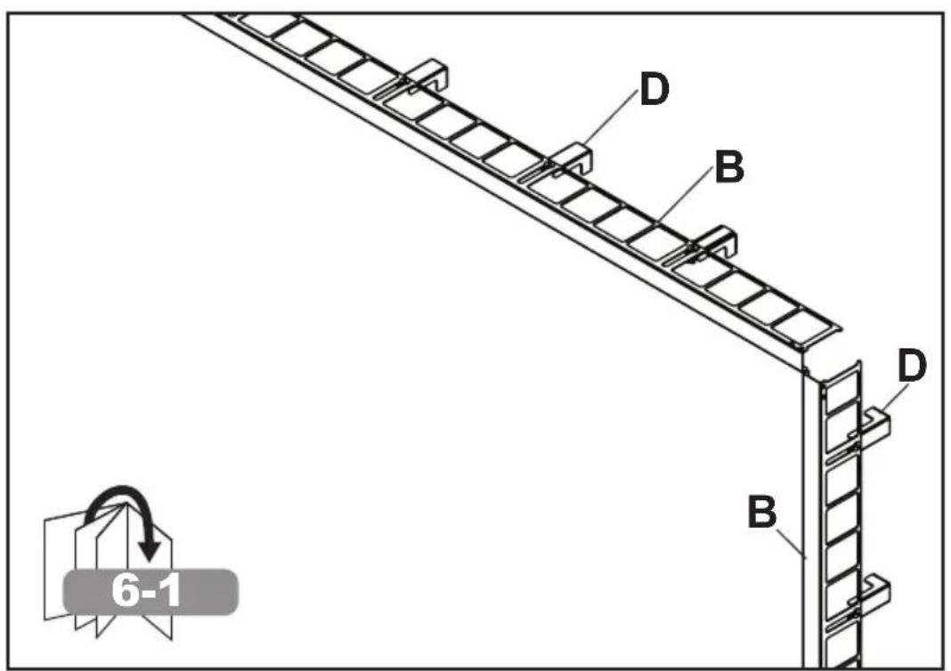
Alternate steps for Unilumin UpanelS sides with bump-outs start on page 22.
2-1
ENG Measure video wall dimensions.
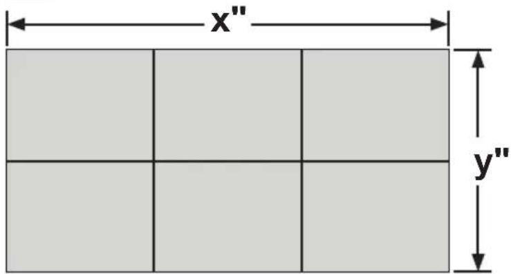
2-2
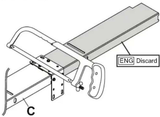
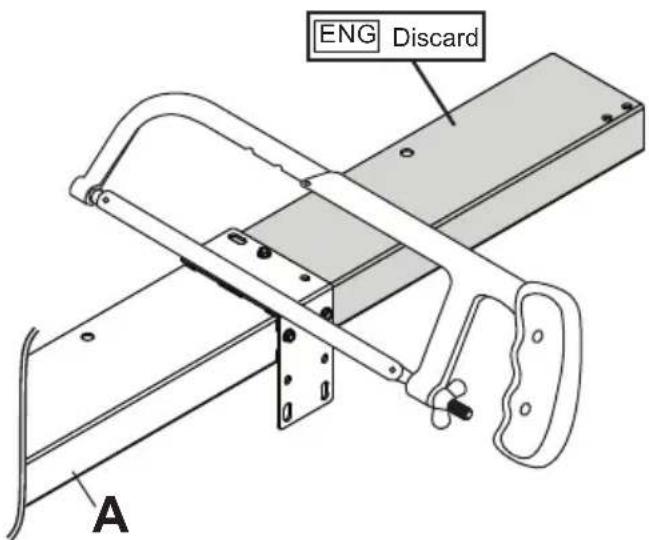
ENG Mark cutting line on wall plates and covers. Do not join covers until installing covers to the wall.
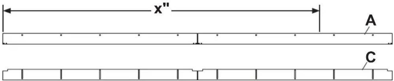
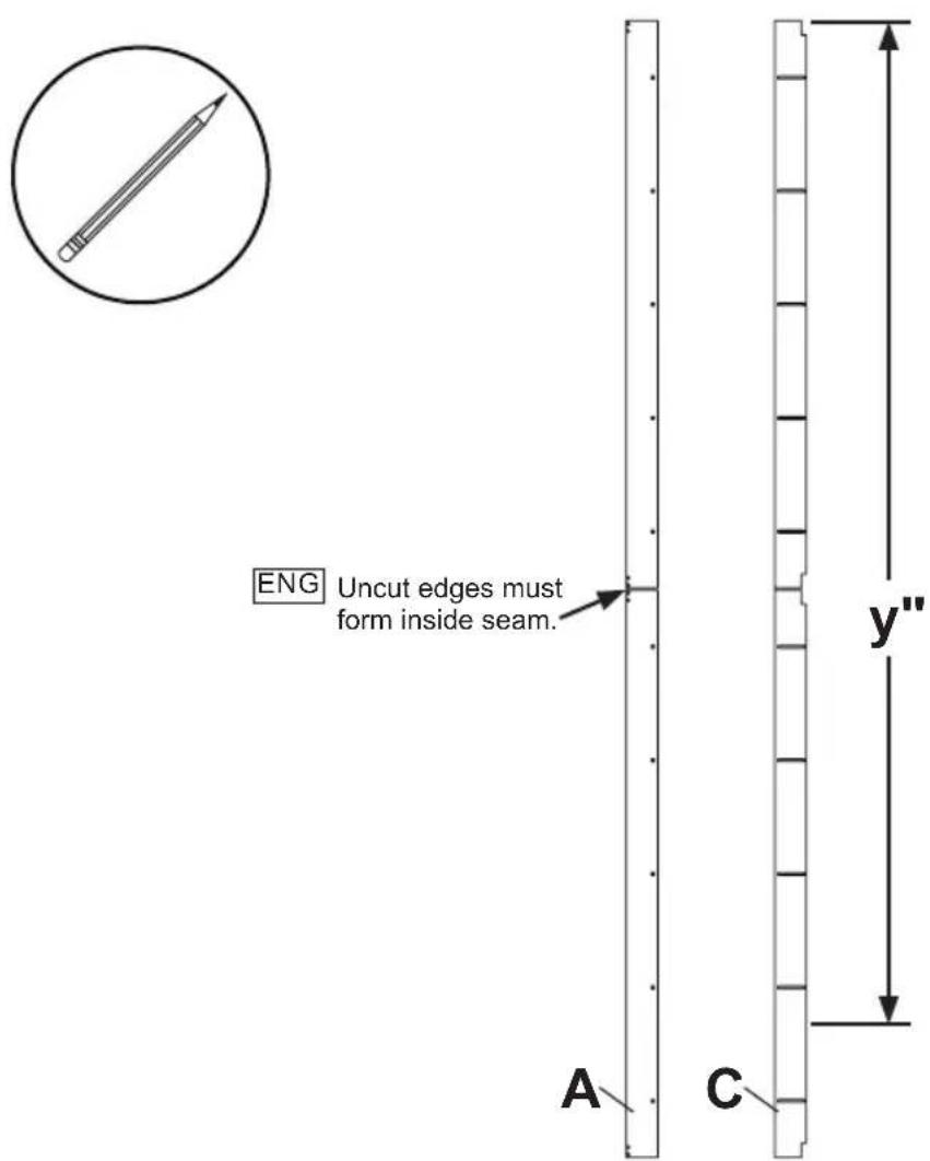
3-1
ENG
Optional: Clamp or fasten cutting fixture to side of cover being discarded.
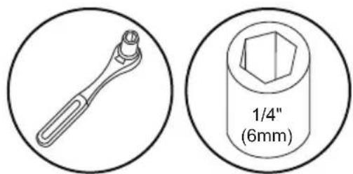
R (4)
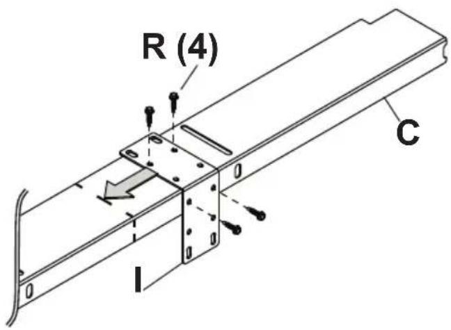
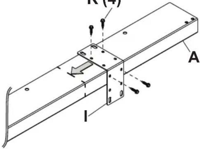
3-2
WARNING
ENG - When installing Peerless wall mounts on a wood stud wall covered with plywood, verify that the wood studs are a minimum of 2" x 4" nominal size and plywood is a minimum Grade BC, 1/2" (13 mm) thick. Plywood may be covered by gypsum board (drywall) up to 5/8" thick.
4-1
ENG Align wallplates with edge of video wall, using spacer to set final position.
natural_image
Simple line drawing of a pencil inside a circle (no text or symbols)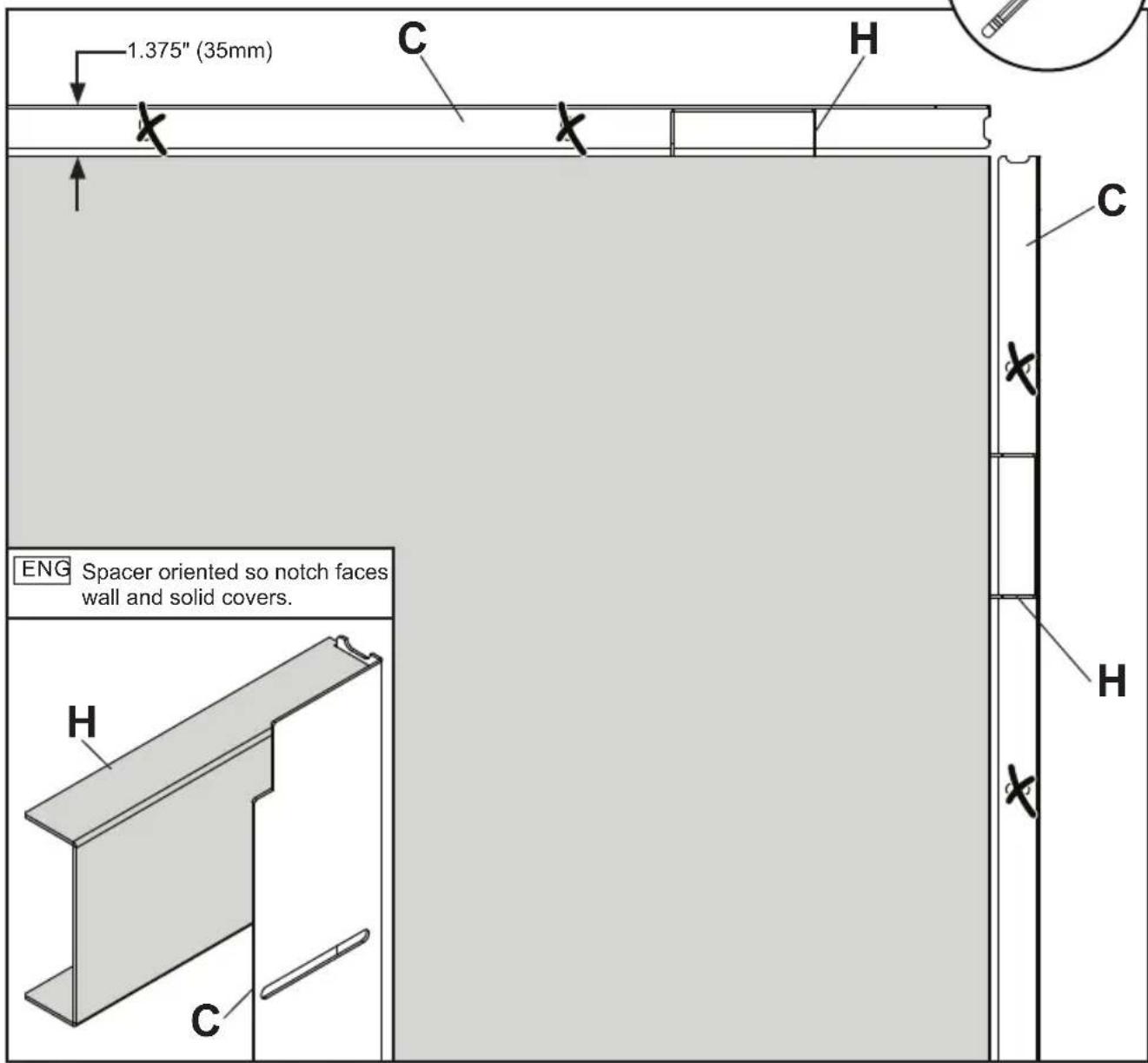
4-2
natural_image
Line drawing of a handheld electric drill (no text or symbols)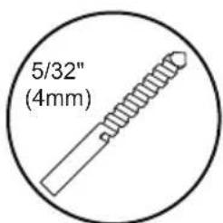
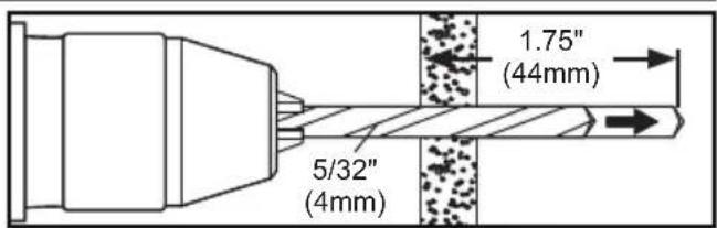
ENG Drill mounting holes into supporting surface (1.75" (44mm) minimum depth required).
4-3

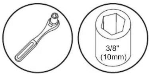
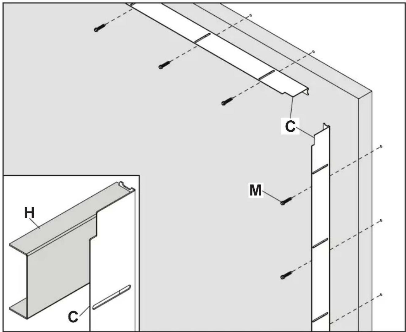
Install using wood screws provided. Use spacer to set final position of wall bracket.
5-1
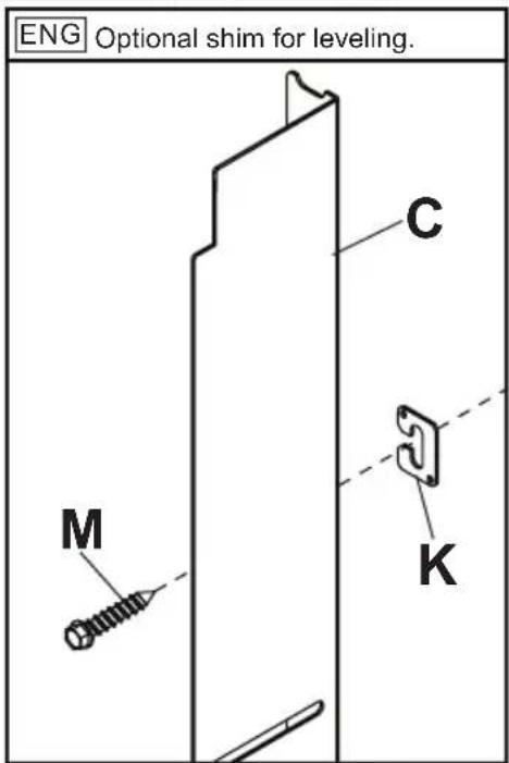
ENG Place wall plate cover over wall plate. Slide back until flush with front of video wall.
5-2
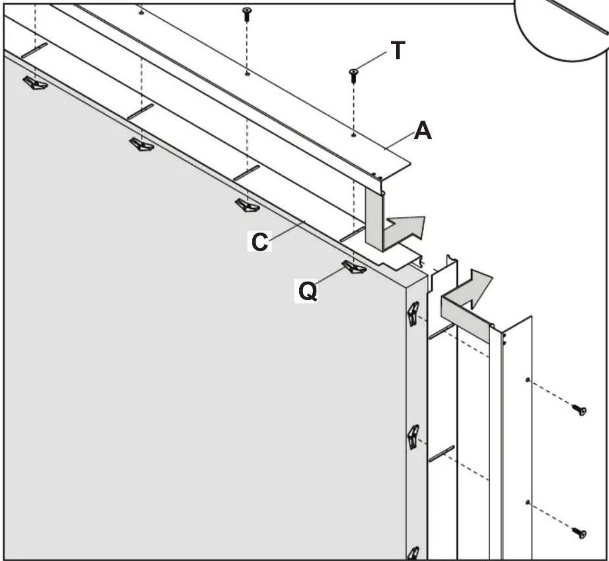
ENG Attach covers with nut bar inside cover. Displays not shown for clarity.
natural_image
Simple line drawing of a screwdriver inside a circle (no text or symbols)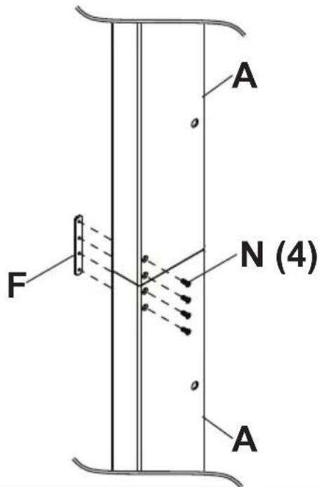
5-3
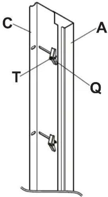
ENG Attach tooglers loosely, one at a time. Then, tighten all. Displays not shown for clarity.
5-4
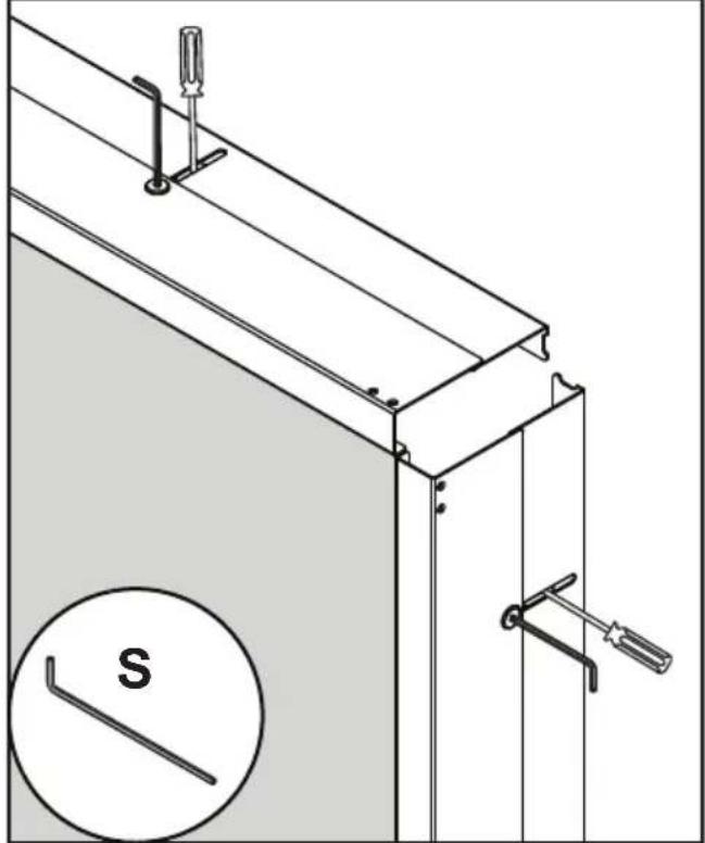
ENG Use screwdriver to hold toggler in place while tightening toggler screws.
natural_image
Technical line drawing of a structural panel assembly with clamps and a magnified inset showing a 'S' symbol (no text or labels)5-5
natural_image
Technical line drawing of a structural assembly with labeled component 'P' (no text or symbols beyond label)
6-1
ENG To begin installing perforated trim, create guiding line around unit using spacer provided.
6-2
ENG Measure video wall dimensions.
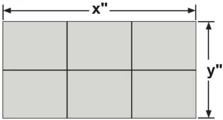
6-3
ENG Mark cutting line on covers. Do not join covers until installing covers to the wall. Leave top and right cover edges uncut for proper alignment.
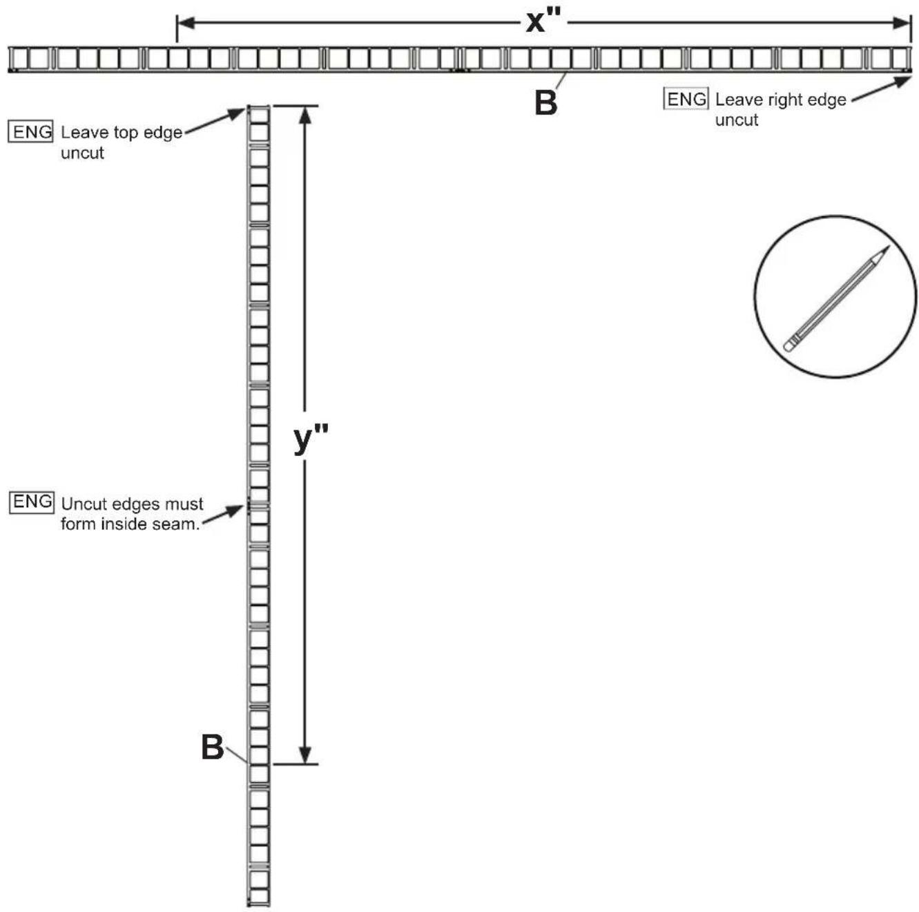
7-17-
ENG
Optional: Clamp or fasten cutting fixture to side of cover being discarded.
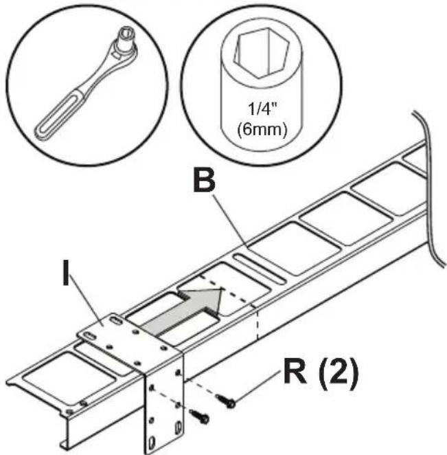
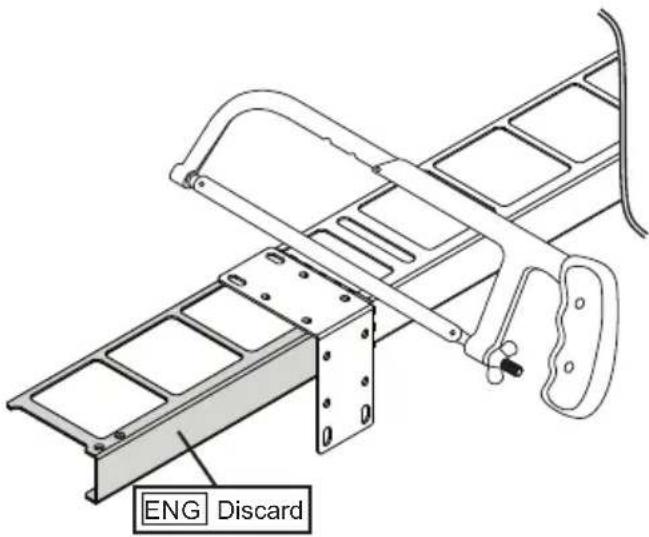
8-1
ENG
Align bottom of spacer cutout and vertical notch with guiding lines.
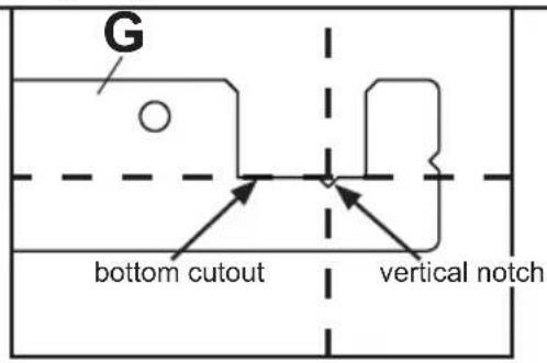
ENG
Align bottom of spacer cutout and horizontal notch with guiding lines.
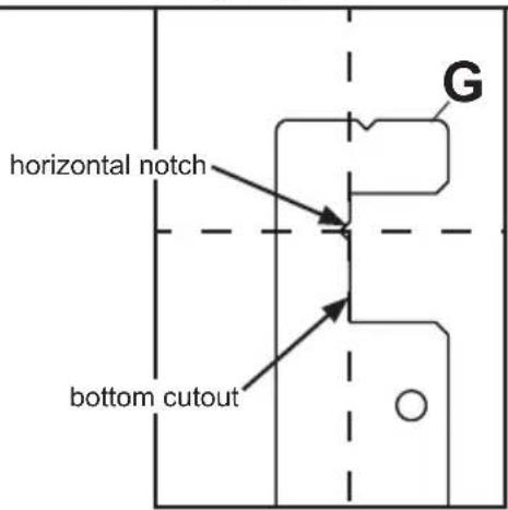
8-2
ENG
For 5 ft. covers, install first bracket in the middle space, then every 12". Optional: Use wood screws to hold spacer in place.
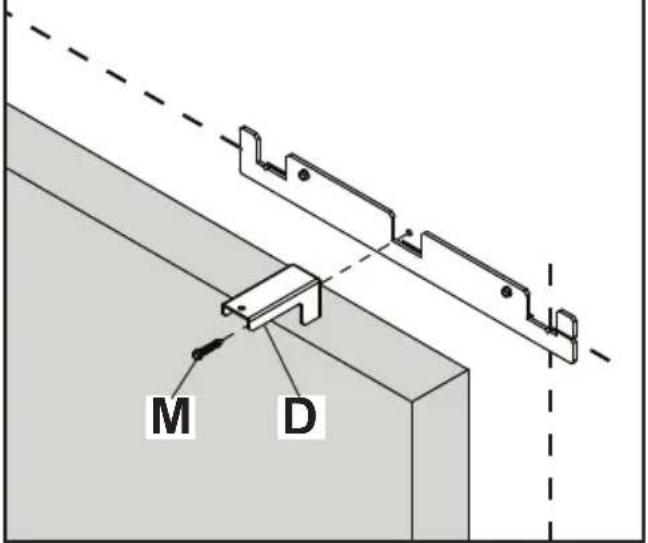
ENG
For 5 ft. covers, install first bracket in the middle space, then every 12". Optional: Use wood screws to hold spacer in place.
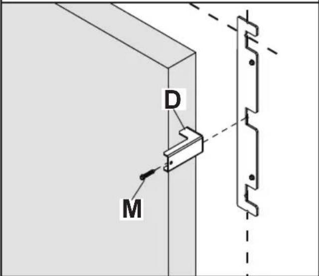
ENG
For 6 - 8 ft. covers, install first bracket at the end space, then every 12". Optional: Use wood screws to hold spacer in place.
ENG
For 6 - 8 ft. covers, install first bracket at the end space, then every 12". Optional: Use wood screws to hold spacer in place.
8-3
ENG
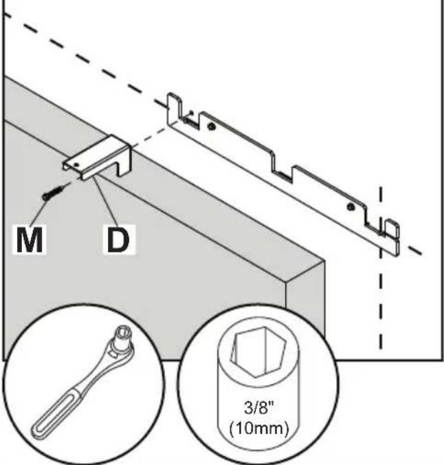
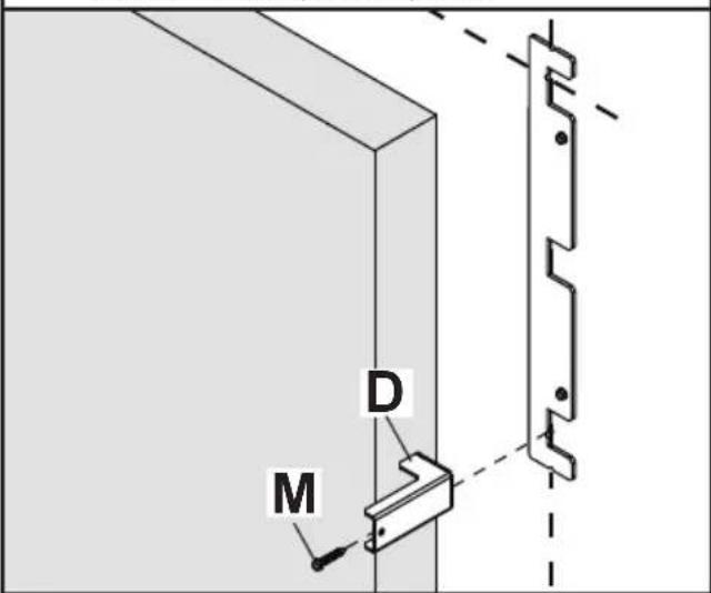
Keep wallplates level using spacer. Install every 12" with wood screws provided.
natural_image
Line drawing of a wrench inside a circle (no text or symbols)

9-1
ENG
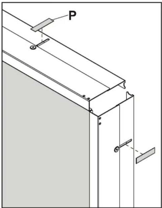
Place top wall plate. Slide back until flush with front of video wall. Secure with hardware.
9-2
ENG
Attach covers with nut bar inside cover. Displays not shown for clarity.
natural_image
Simple line drawing of a screwdriver inside a circle (no text or symbols)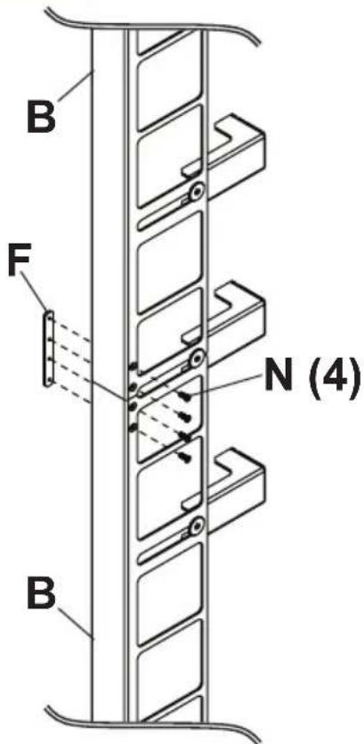
10-1
ENG
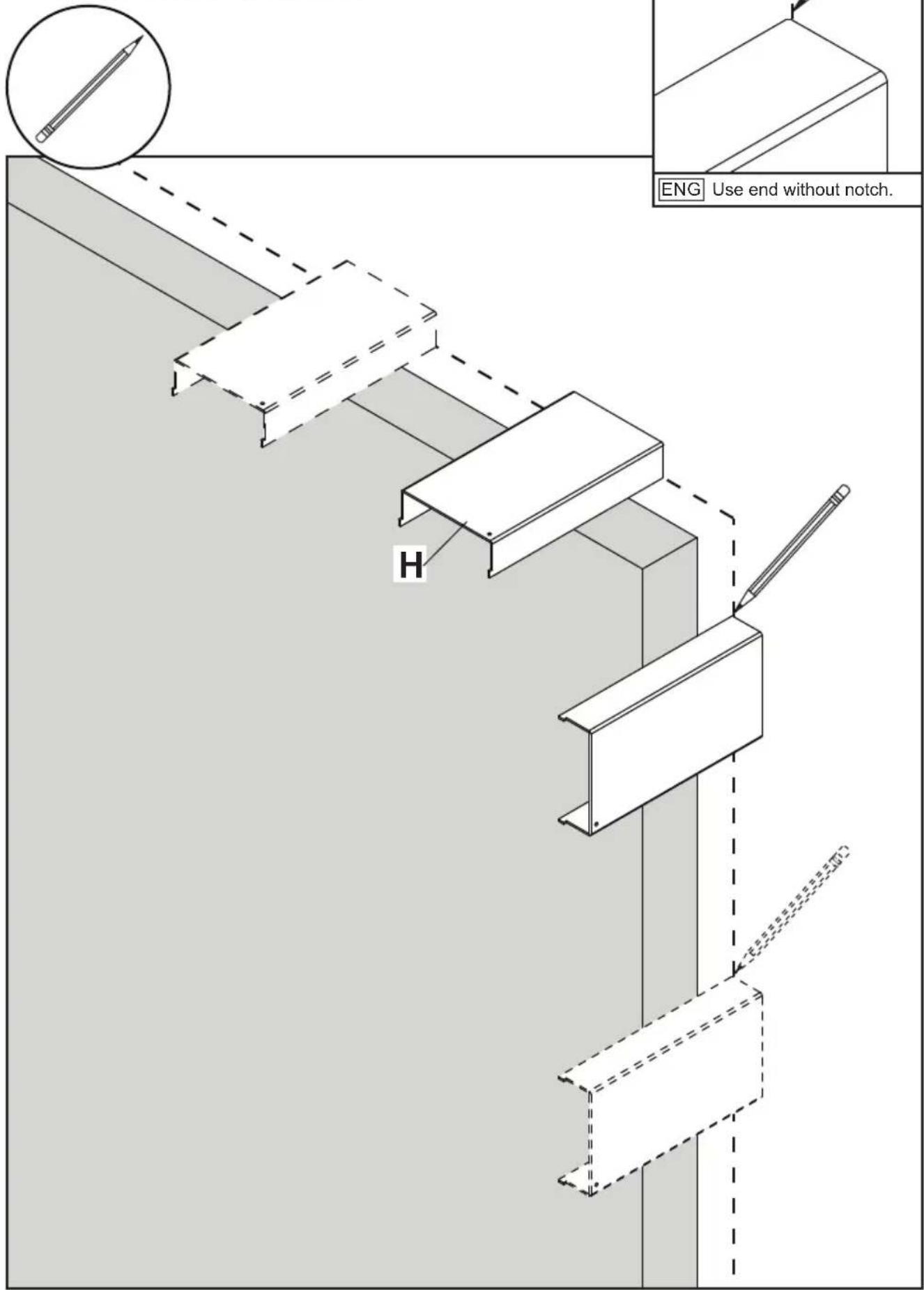
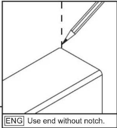
Place corner cover against wall and mark cutting line.
natural_image
Simple line drawing of a mechanical component inside a circle (no text or symbols)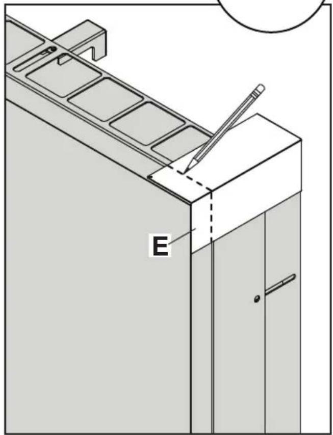
10-2
ENG
Slide corner cutting fixture into place and clamp on side of cover being discarded.
10-3
ENG
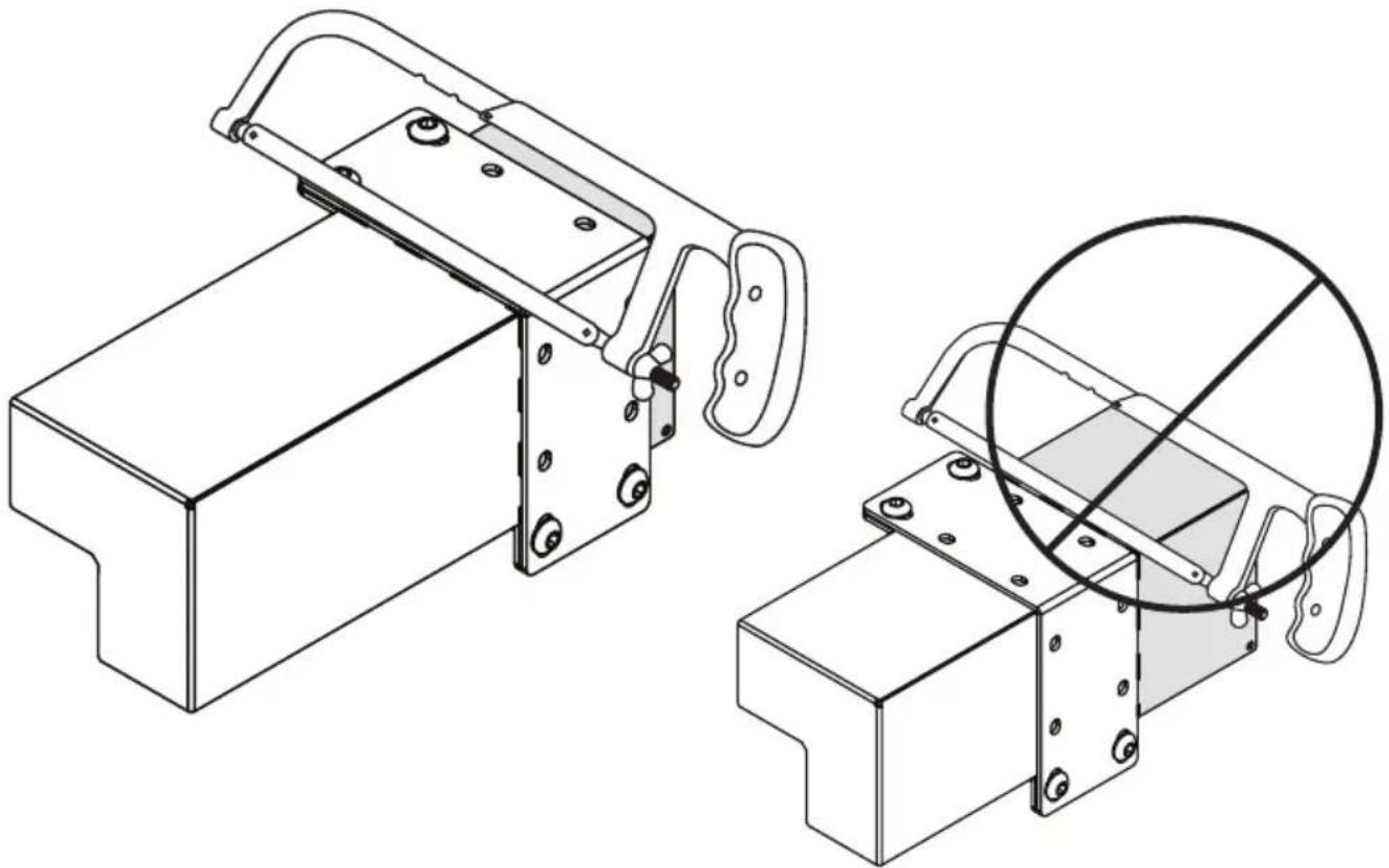
Cut excess corner cover off.
natural_image
Technical line drawing of two mechanical components with mounting brackets and a circular inset showing a cross-section (no text or symbols)
Do not clamp fixture on wrong side of cutting line.
10-4
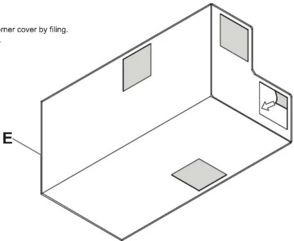
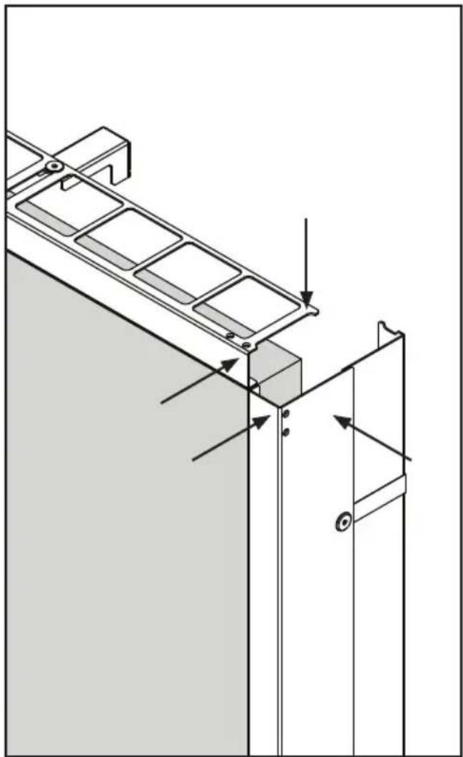
ENG Remove sharp edges of corner cover by filing. Remove adhesive backing.
x4
10-51
ENG Clean surfaces before applying VHB.
natural_image
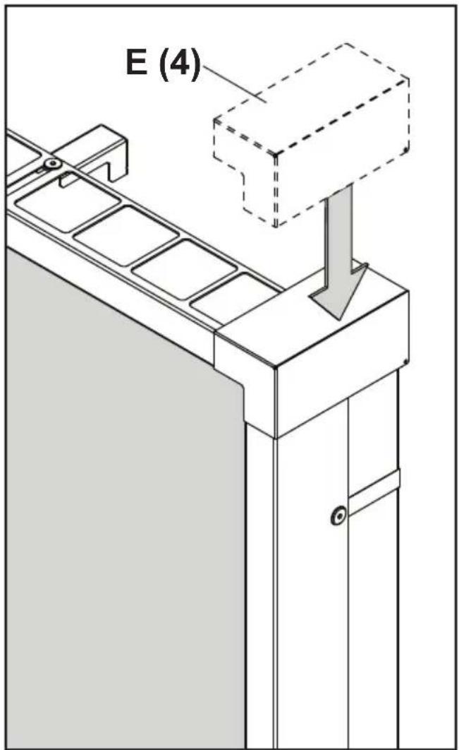
Technical line drawing of a structural joint or panel assembly (no text or symbols present)ENG Attach (4) corner covers with VHB.
Alternate steps for Unilumin UpanelS sides with bump-outs
2
ENG
To begin installing solid trim on Unilumin UpanelS edges with bumpouts, create guiding line around unit using spacer provided.
natural_image
Simple line drawing of a pencil inside a circle (no text or symbols)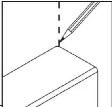
natural_image
Pure technical line drawing of a mechanical part with a pencil, no text or symbols present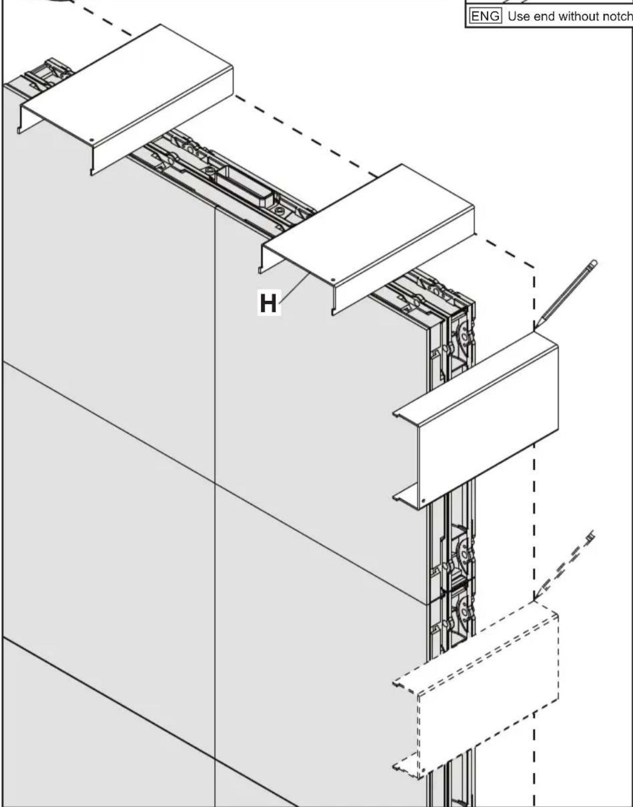
2-1
ENG Measure video wall dimensions
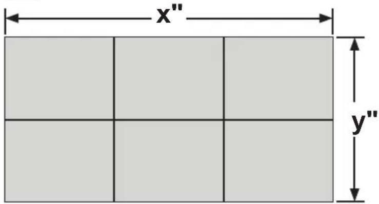
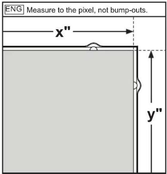
4-1
ENG Align wall plates with display guiding lines. Mark mounting holes.
natural_image
Two circular diagrams: one showing a mechanical component with a shaft, the other showing a pencil (no text or symbols)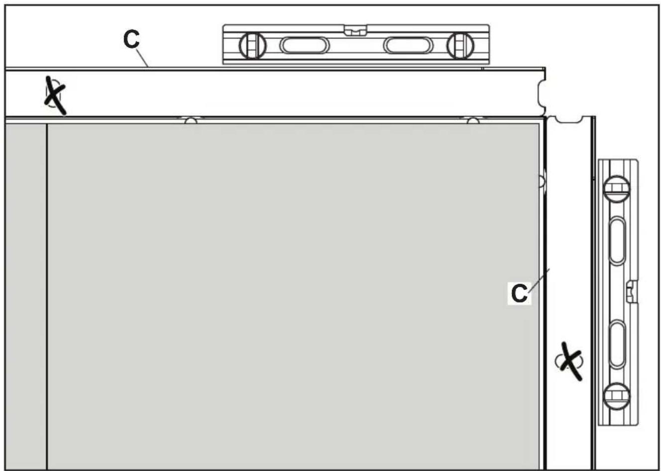
4-3
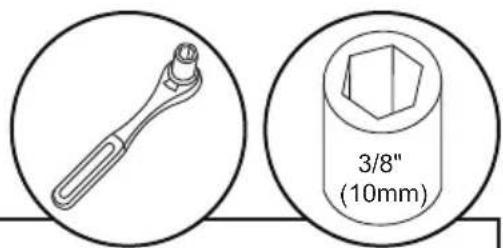
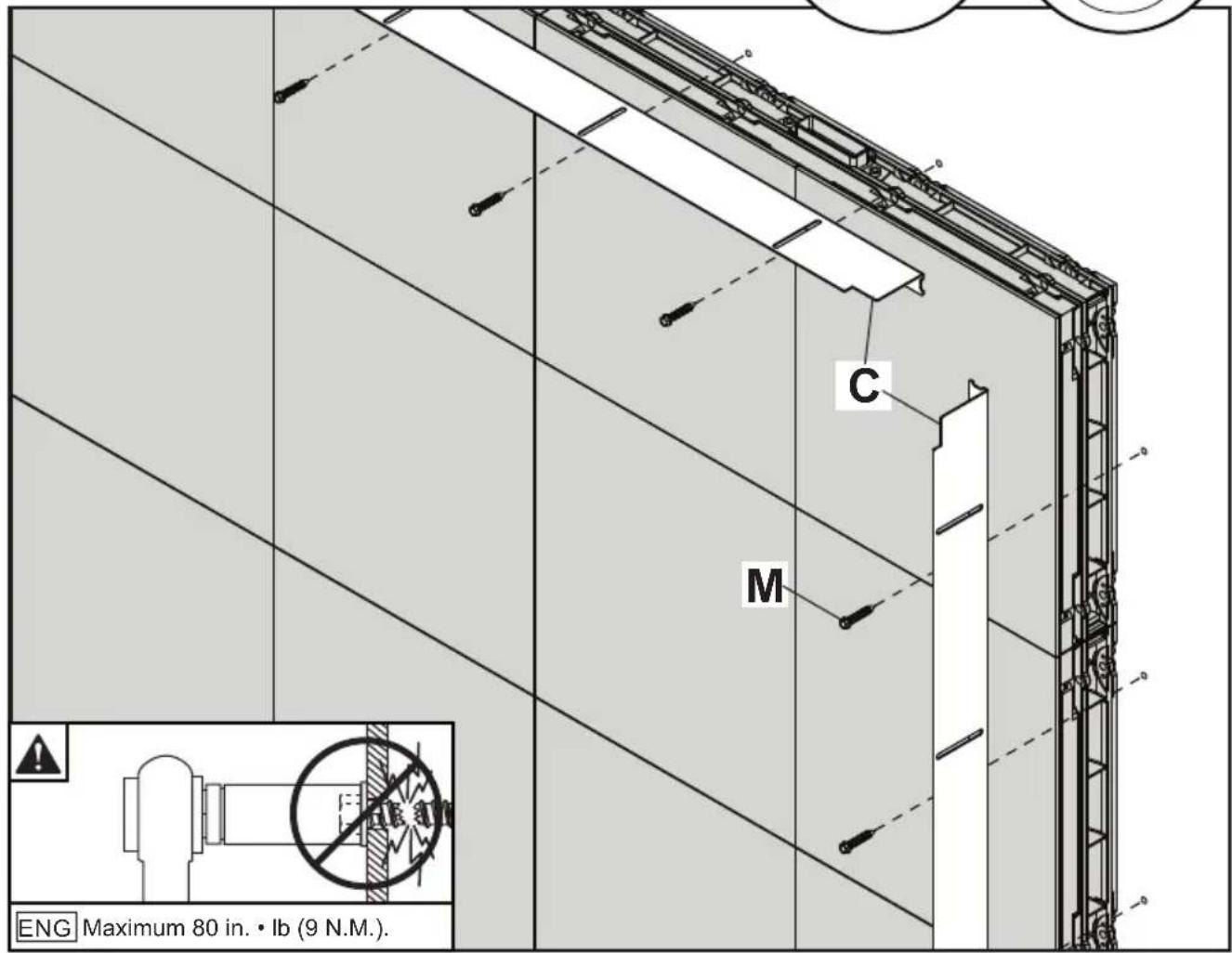
ENG Install using wood screws provided.
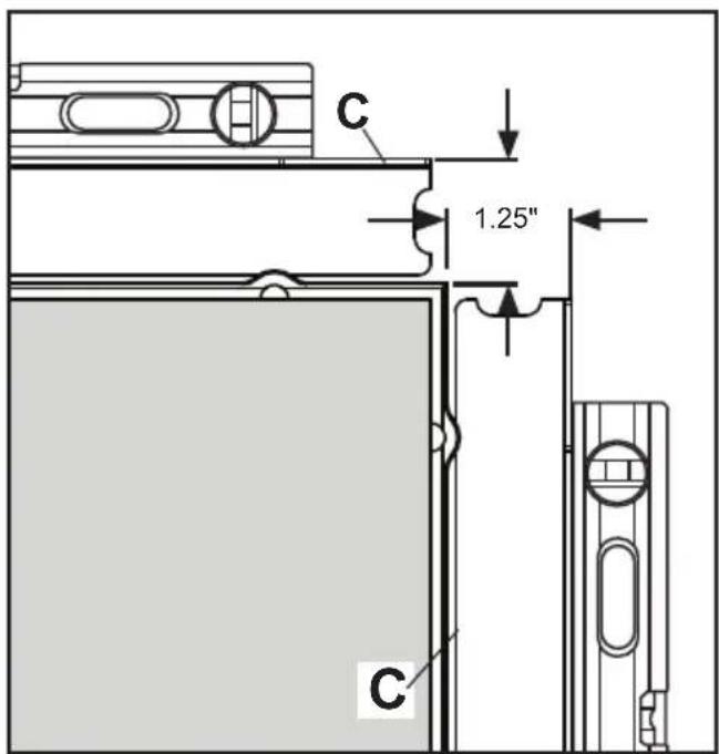
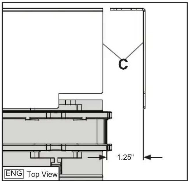
ENG Slide wall brackets in slot until they sit 1.25" from display guiding lines. Level and tighten wood screws.
6-1
ENG
To begin installing perforated trim on Unilumin UpanelS edges with bump-outs, create guiding line around unit using spacer provided.
natural_image
Simple line drawing of a pencil inside a circle (no text or symbols)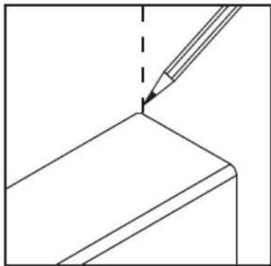
natural_image
Pure technical line drawing of a 3D geometric shape with a pencil, no text or symbols present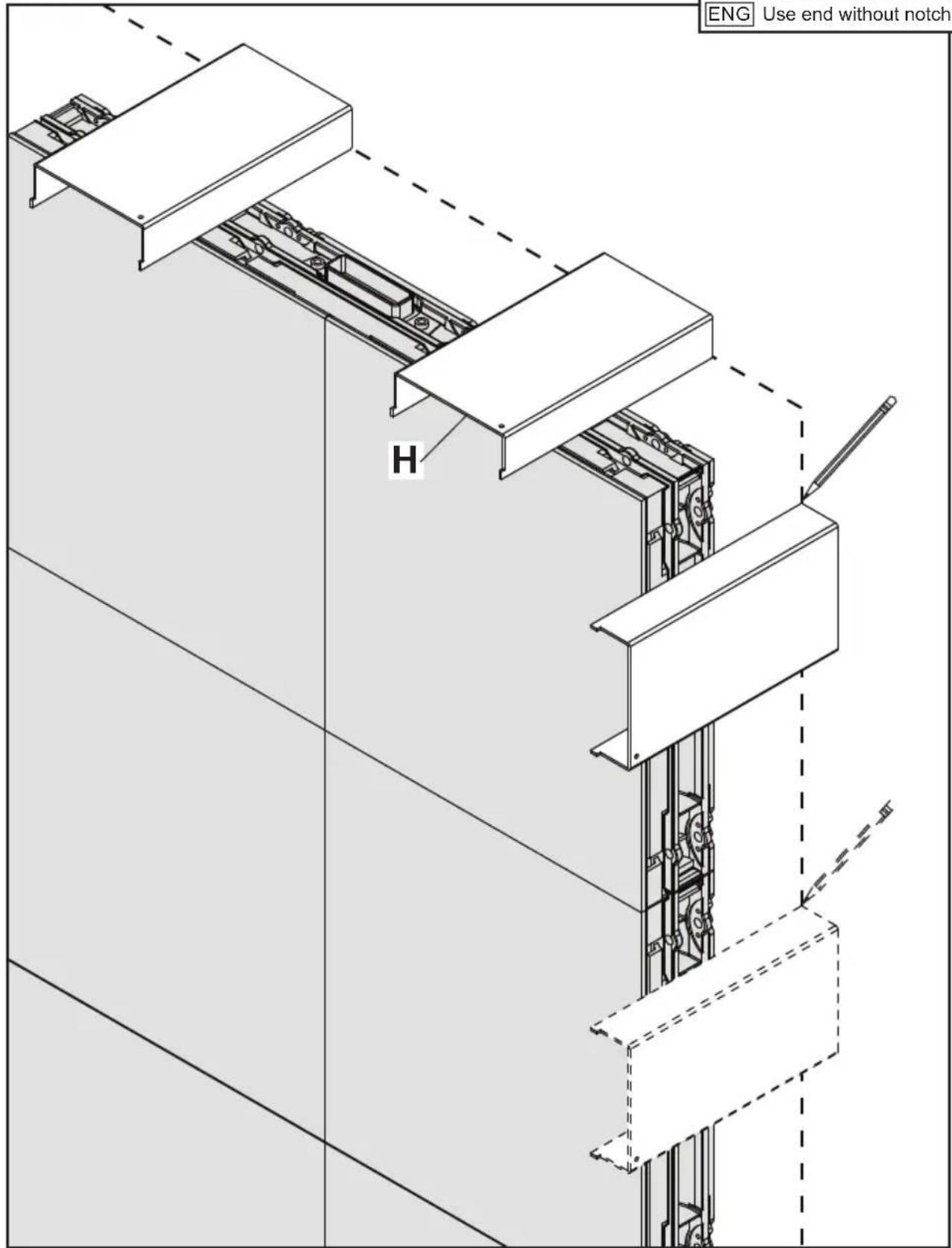
6-2
ENG Measure video wall dimensions
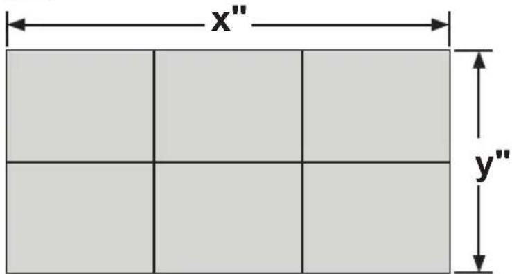
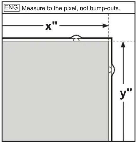
8-1
ENG
To avoid the display bump-outs, align vertical and horizontal notch with guiding lines.
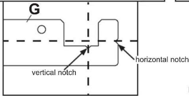
ENG
To avoid the display bump-outs, align vertical and horizontal notch with guiding lines.
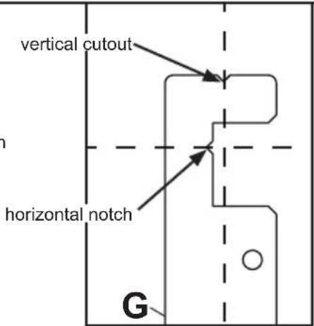
8-2
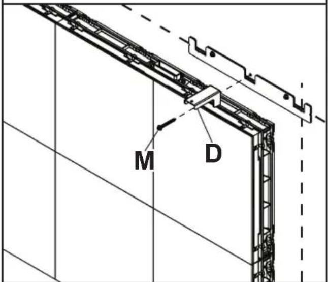
ENG
For 5 ft. covers, install first bracket in the middle space, then every 12". Optional: Use wood screws to hold spacer in place.
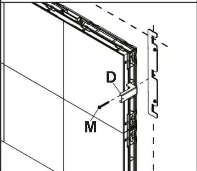
ENG
For 5 ft. covers, install first bracket in the middle space, then every 12". Optional: Use wood screws to hold spacer in place.
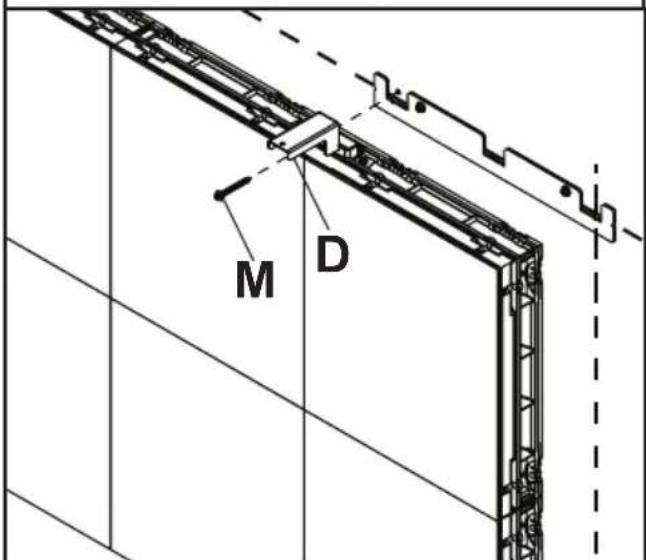
ENG
For 6 - 8 ft. covers, install first bracket at the end space, then every 12". Optional: Use wood screws to hold spacer in place.
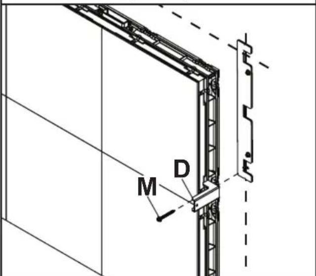
ENG
For 6 - 8 ft. covers, install first bracket at the end space, then every 12". Optional: Use wood screws to hold spacer in place.
8-3

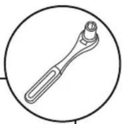
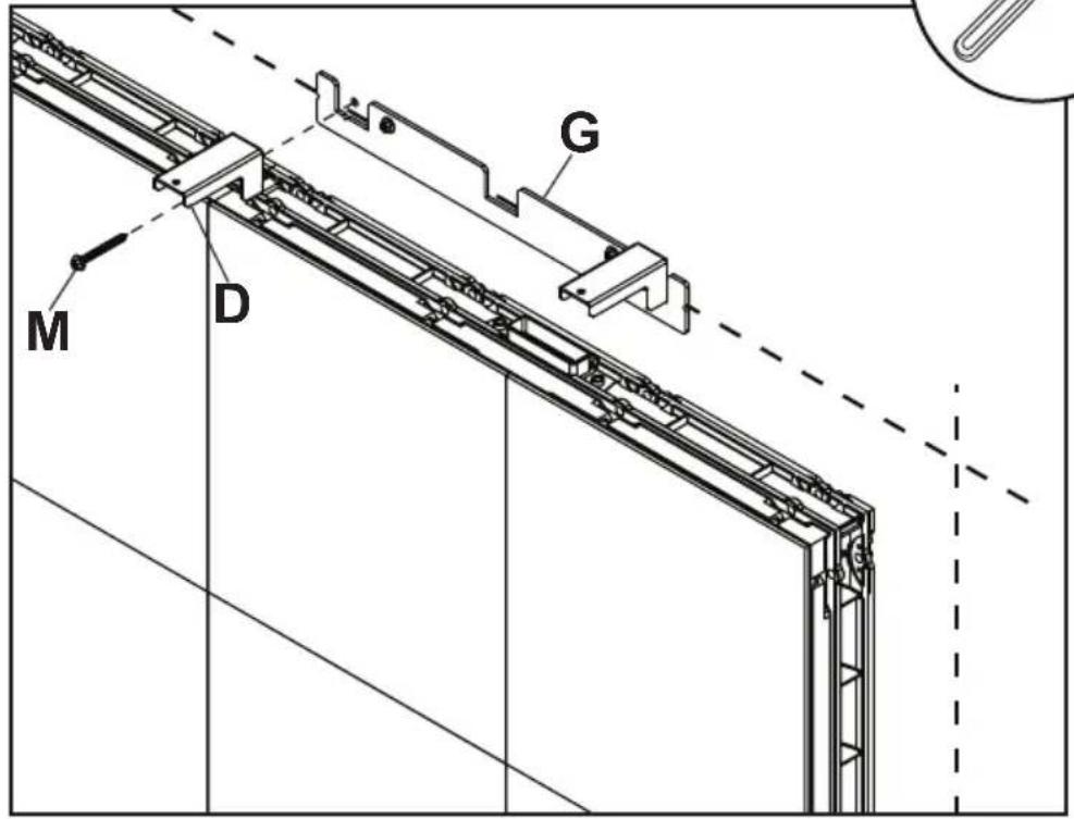
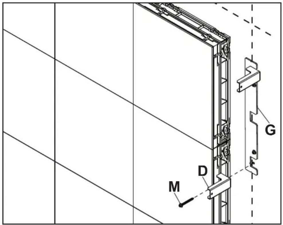
Keep wallplates level using spacer. Install every 12" with wood screws provided.
natural_image
Line drawing of a wrench inside a circle (no text or symbols)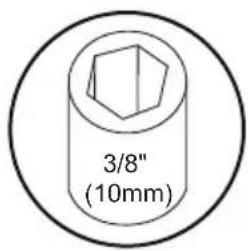
www.peerless-av.com/warranty
peerless-AV®
Peerless-AV
2300 White Oak Circle
Aurora, IL 60502
Email: tech@peerlessmounts.com
Ph: (800) 865-2112
Fax: (800) 359-6500
www.peerless-av.com
Peerless-AV Europe
Unit 3 Watford Interchange,
Colonial Way, Watford, Herts,
WD24 4WP, United Kingdom
Customer Care
44 (0) 1923 200 100
www.peerless-av.com
Peerless-AV América Latina

- WARNING
- 8-18 X 3/4"
- 14-10 x 1.75 wood screw
- 1
- 2-1
- 2-2
- 3-1
- 3-2
- 4-1
- 4-2
- 4-3
- 5-1
- 5-2
- 5-3
- 5-4
- 5-5
- 6-1
- 6-2
- 6-3
- 7-17-
- 8-1
- 8-2
- 8-3
- 9-1
- 9-2
- 10-1
- 10-2
- 10-3
- 10-4
- 10-51
- Alternate steps for Unilumin UpanelS sides with bump-outs
- 2
- www.peerless-av.com/warranty
- peerless-AV®
- Peerless-AV
- Peerless-AV Europe
- Peerless-AV América Latina
Brand : Peerless-AV
Model : DS-LEDTK-6S
Category : Wall mount for screen