
DS-MBY942L-2X1 - Wall mount for screen Peerless-AV - Free user manual and instructions
Find the device manual for free DS-MBY942L-2X1 Peerless-AV in PDF.

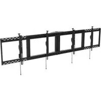
| Product Type | Dual Monitor Wall Mount |
| Brand | Peerless-AV |
| Model | DS-MBY942L-2X1 |
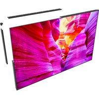
| Compatible Screen Size | 42" to 94" |
| VESA Compatibility | 200x200mm to 900x600mm |
| Weight Capacity (per screen) | 250 lbs (113 kg) |
| Material | Steel with black powder coat finish |
| Wall Plate Dimensions | 42" x 12" (1067 x 305 mm) |
| Depth from Wall | 4.5 inches (114 mm) |
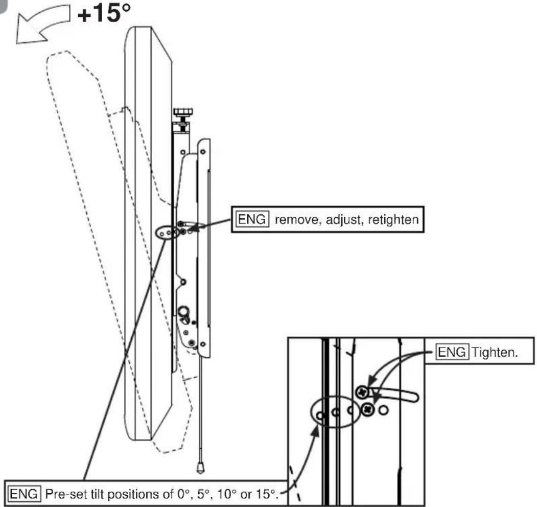
| Tilt Range | +/- 15 degrees |
| Swivel Range | +/- 90 degrees |
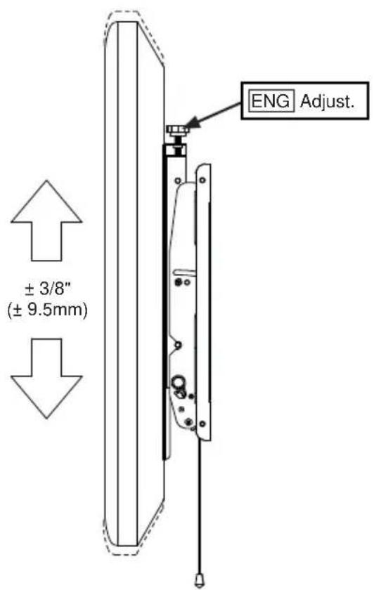
| Level Adjustment | +/- 3 degrees post-installation |
| Mount Weight | 45 lbs (20 kg) |
| Power Requirement | None (manual adjustment) |
| Maintenance | Wipe with a damp cloth; avoid solvents |
| Safety Certifications | UL and TUV listed |
| Installation Method | Smart Solutions™ technology for easy leveling |
| Spare Parts Availability | Contact Peerless-AV for replacement hardware |
| Repair Policy | 5-year limited warranty |
Frequently Asked Questions - DS-MBY942L-2X1 Peerless-AV
User questions about DS-MBY942L-2X1 Peerless-AV
0 question about this device. Answer the ones you know or ask your own.
Ask a new question about this device
Download the instructions for your Wall mount for screen in PDF format for free! Find your manual DS-MBY942L-2X1 - Peerless-AV and take your electronic device back in hand. On this page are published all the documents necessary for the use of your device. DS-MBY942L-2X1 by Peerless-AV.
USER MANUAL DS-MBY942L-2X1 Peerless-AV
ENG This page intentionally left blank
WARNING
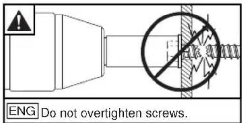
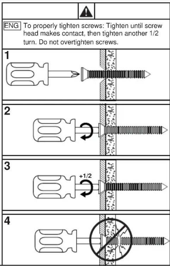
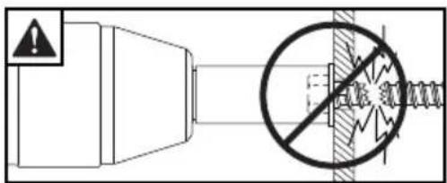
ENG - This product is designed to be installed on wood joist/beam or solid concrete ceilings. Hardware is included for wood joist/beam and solid concrete installation. Before installing make sure the supporting surface will support the combined load of the equipment and hardware. Screws must be tightly secured. Do not overtighten screws or damage can occur and product may fail. Never exceed the Maximum Load Capacity. Always use an assistant or mechanical lifting equipment to safely lift and position equipment. This product is intended for indoor use only. Use of this product outdoors could lead to product failure or personal injury. Be careful not to pinch fingers when operating the mount. For support please call customer care at 1-800-865-2112.
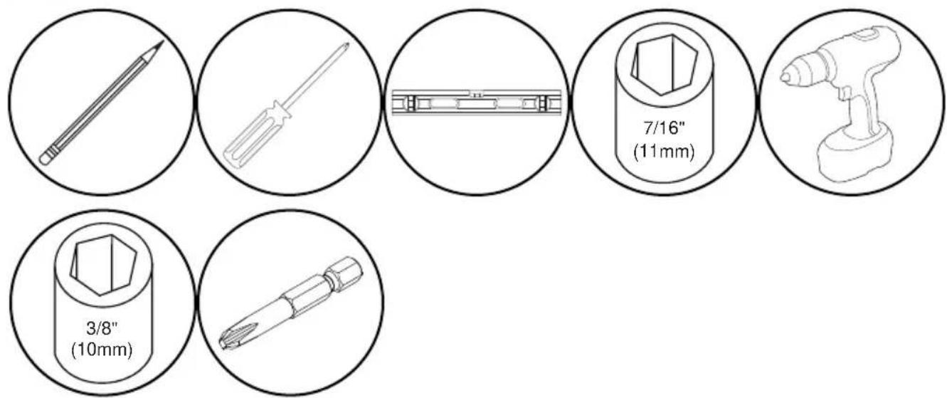
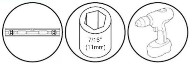
ENG Tools Needed for Assembly.
ENG Parts (Before beginning, make sure you have all parts shown below).
| Parts List | DS-MBY942L-2X1 Part # | DS-MBY947L-2X1 Part #Description Qty |
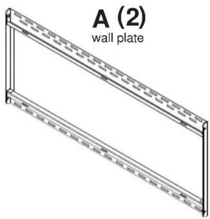
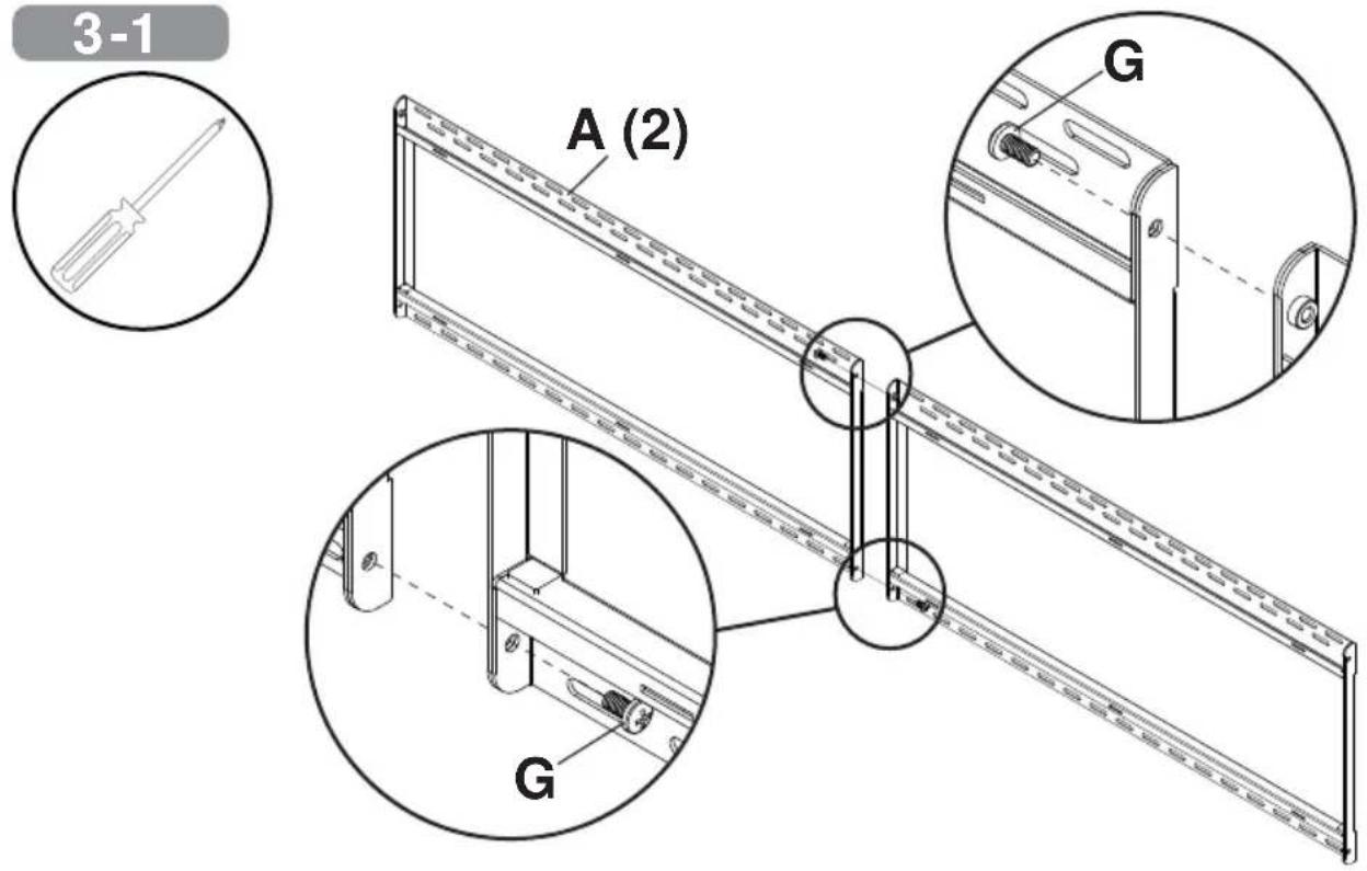
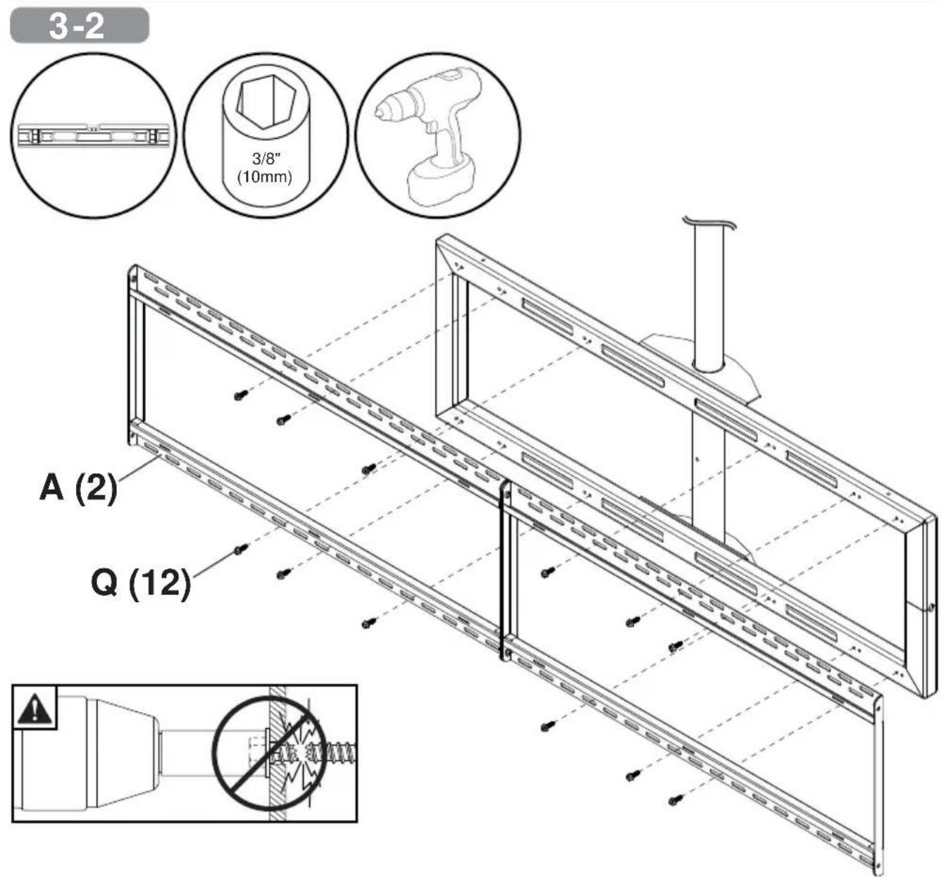
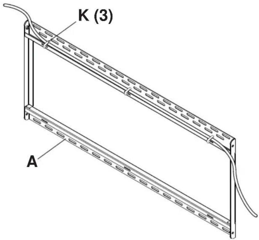
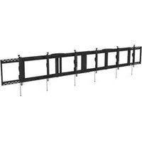
| A wall plate 2 145-1988 145-1991 | ||
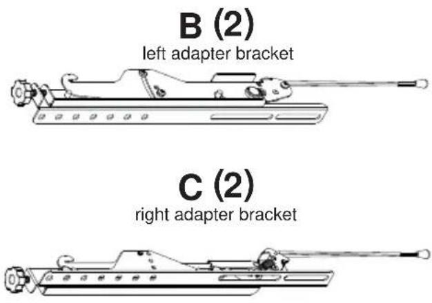
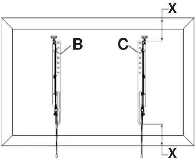
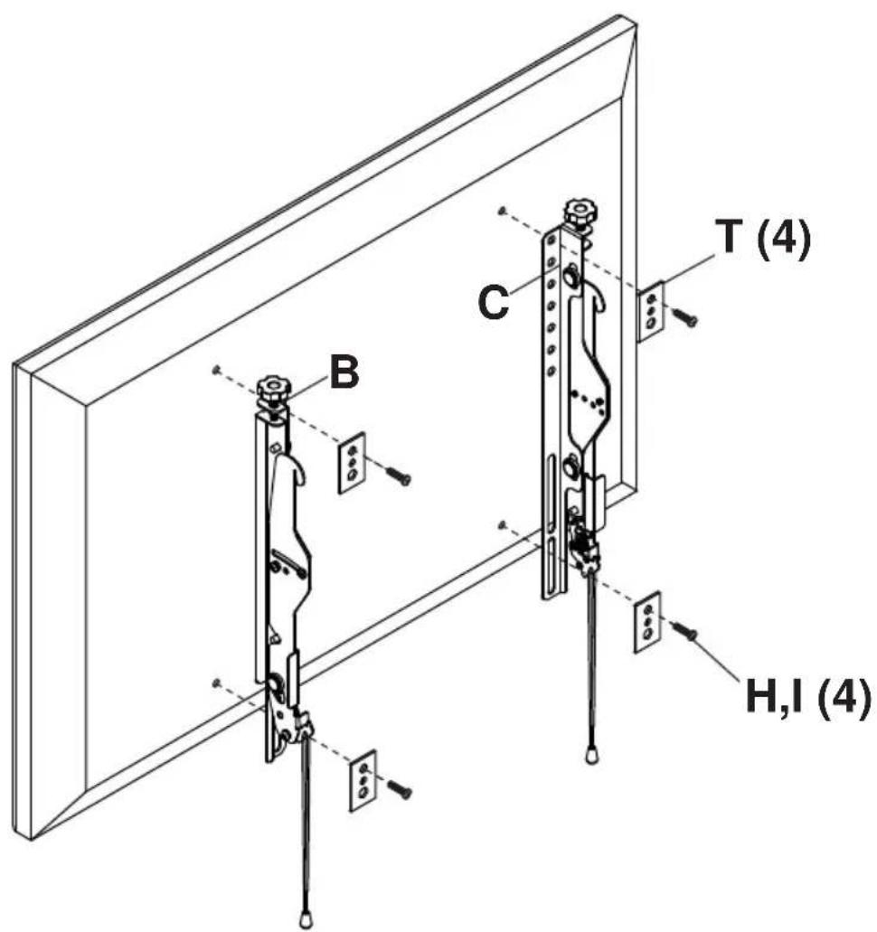
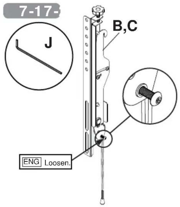
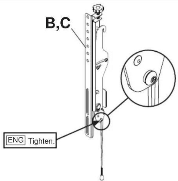
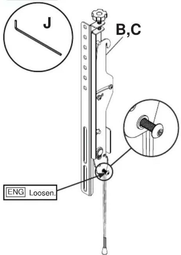
| B left adapter bracket 2 146-1021 146-1021 | ||
| C right adapter bracket 2 146-1020 146-1020 | ||
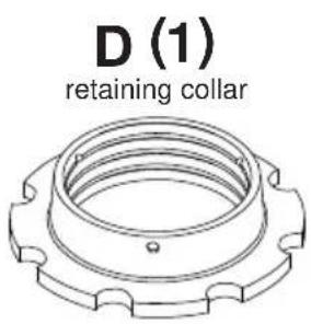
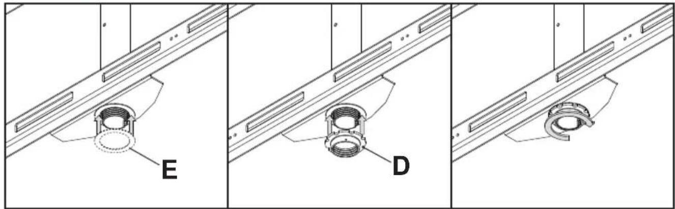
| D retaining collar 1 1800-375 1800-375 | ||
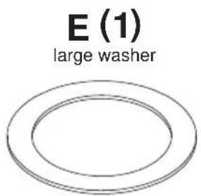
| E large washer 1 540-9432 540-9432 | ||
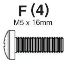
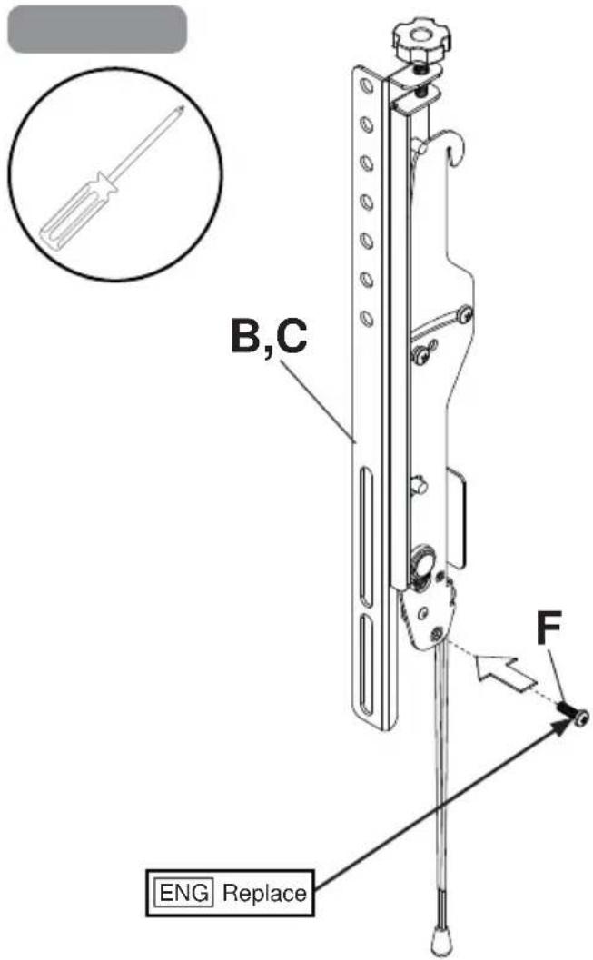
| F M5 x 16mm phillips screw 4 520-1189 520-1189 | ||
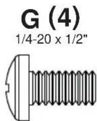
| G 1/4-20 x 1/2" phillips screw 4 510-9108 510-9108 | ||
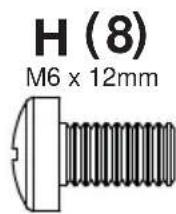
| H M6 x 12mm phillips screw 8 520-1128 520-1128 | ||
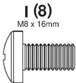
| I M8 x 16mm phillips screw 8 520-9257 520-9257 | ||
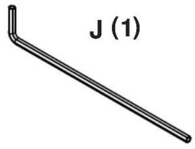
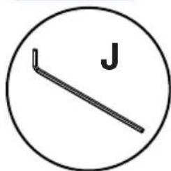
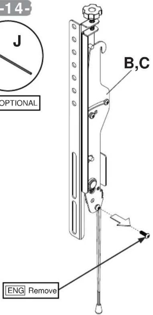
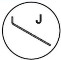
| J 4mm allen wrench | 1 560-9646 560-9646 | |
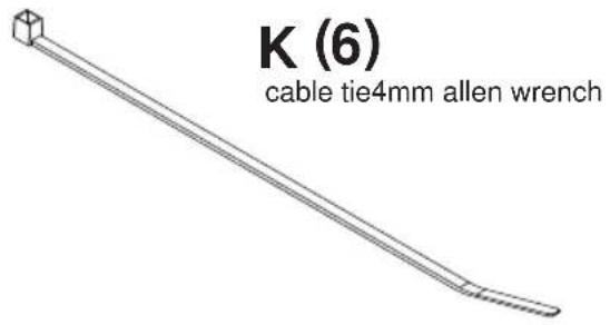
| K cable tie | 6 560-9711 560-9711 | |
| L main frame | 1 146-1048 146-1048 | |
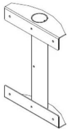
| M main post | 1 146-1052 146-1052 | |
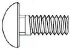
| N carriage bolt | 4 520-1175 520-1175 | |
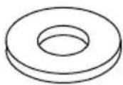
| O small washer | 4 540-9440 540-9440 | |
| P nylock nut | 4 530-9413 530-9413 | |
| Q hex head screw | 12 520-1321 | 520-1321 |
| R #10 x 1/2" phillips screw | 2 520-1320 520-1320 | |
| S M5 x 10mm socket pin screw | 1 520-1164 520-1164 | |
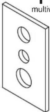
| T multiwasher | 8 580-1398 580-1398 |
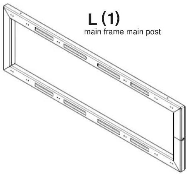
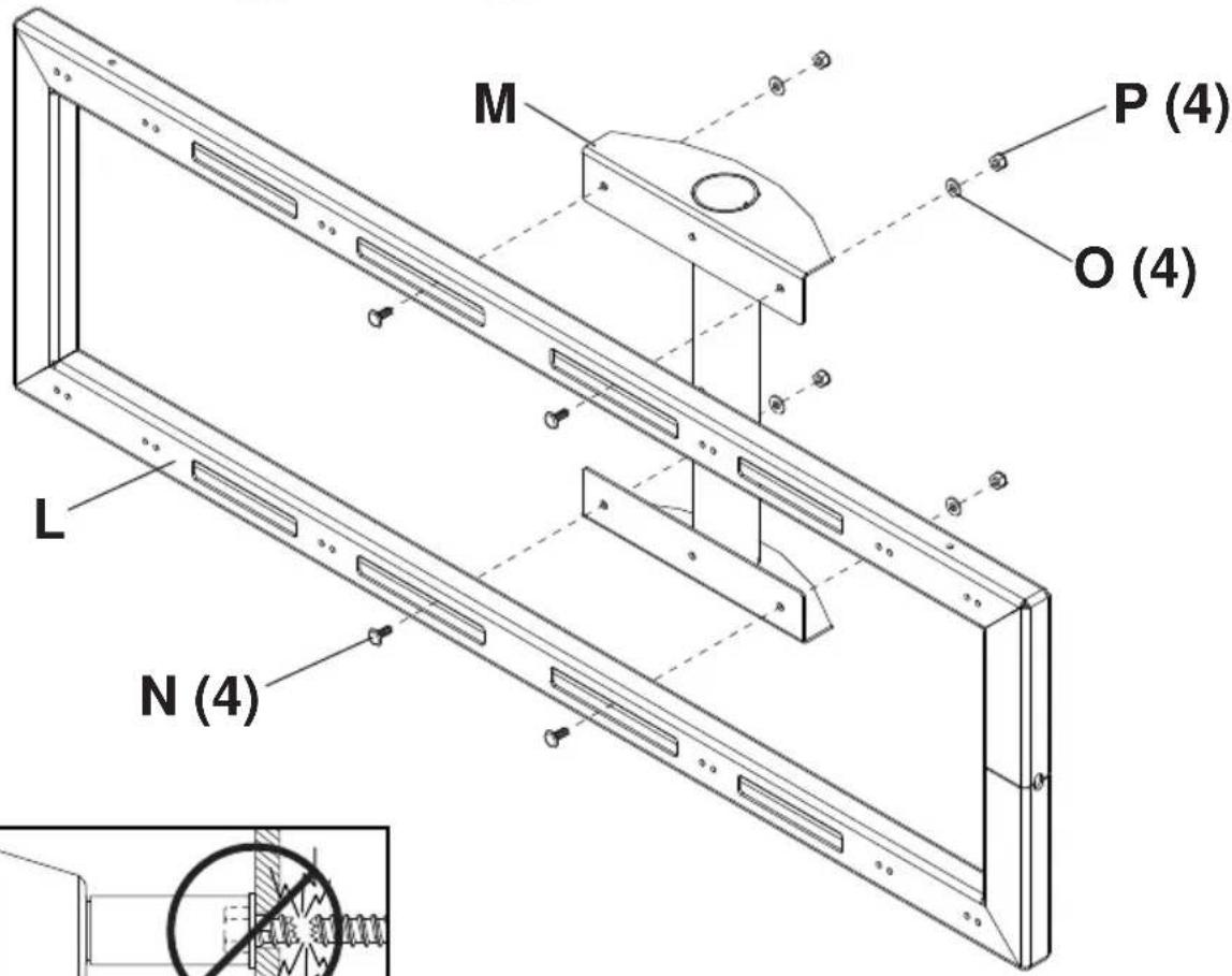
M (1)
N (4)
carriage bolt
O (4)
small washer
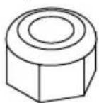
P (4)
nylock nut
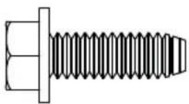
Q (12)
hex head screw
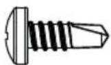
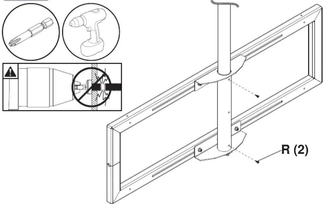
R (2)
10 x 1/2" phillips screw
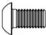
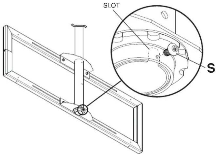
S (1)
M5 x 10mm socket
pin screw
T (8)
multiwasher
1
2-1
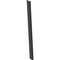
ENG Extension column (sold separately)
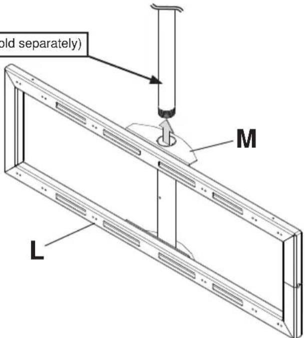
2-2
2-3

Align slot of extension column
2-4
5
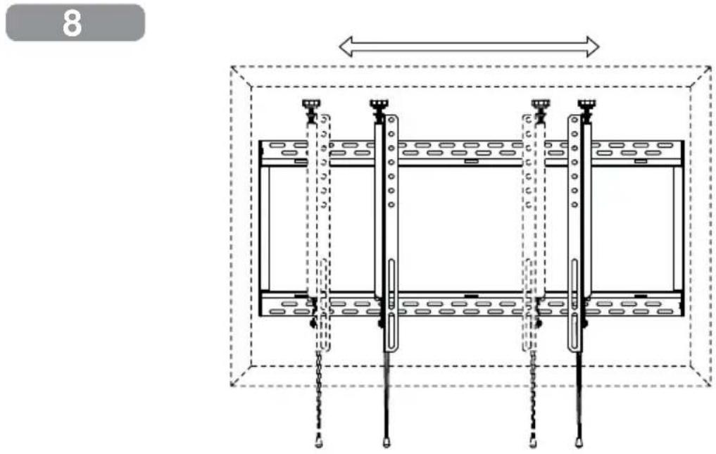
ENG Center adapter brackets vertically on back of screen.
6
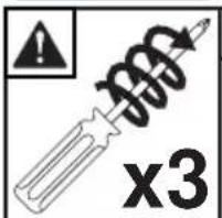
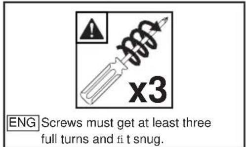
ENG Screws must get at least three full turns and fit snug.
9
10
11
ENG
OPTIONAL: cable management
12-11
13-1
ENG OPTIONAL
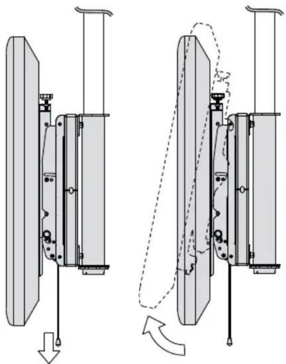
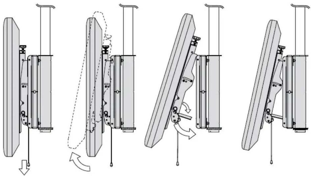
WARNING
ENG Kickstand is for maintenance only
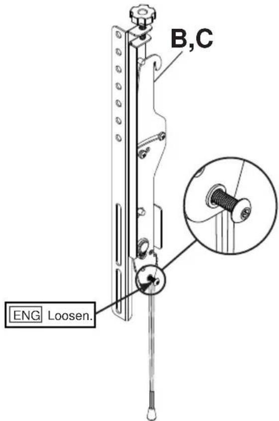
13-2
LIMITED FIVE-YEAR WARRANTY
Peerless Industries, Inc. ("Peerless") warrants to original end-users of Peerless® products will be free from defects in material and workmanship, under normal use, for a period of five years from the date of purchase by the original end-user (but in no case longer than six years after the date of the product's manufacture). At its option, Peerless will repair or replace, or refund the purchase price of, any product which fails to conform with this warranty.
In no event shall the duration of any implied warranty of merchantability or fitness for a particular purpose be longer than the period of the applicable express warranty set forth above. Some states do not allow limitations on how long a implied warranty lasts, so the above limitation may not apply to you.
This warranty does not cover damage caused by (a) service or repairs by the customer or a person who is not authorized for such service or repairs by Peerless, (b) the failure to utilize proper packing when returning the product, (c) incorrect installation or the failure to follow Peerless' instructions or warnings when installing, using or storing the product, or (d) misuse or accident, in transit or otherwise, including in cases of third party actions and force majeure.
In no event shall Peerless be liable for incidental or consequential damages or damages arising from the theft of any product, whether or not secured by a security device which may be included with the Peerless® product. Some states do not allow the exclusion or limitation of incidental or consequential damages, so the above limitation or exclusion may not apply to you.
This warranty is in lieu of all other warranties, expressed or implied, and is the sole remedy with respect to product defects. No dealer, distributor, installer or other person is authorized to modify or extend this Limited Warranty or impose any obligation on Peerless in connection with the sale of any Peerless ® product.
This warranty gives specific legal rights, and you may also have other rights which vary from state to state.
peerless-AV®
Peerless-AV
2300 White Oak Circle
Aurora, IL 60502
Email: tech@peerlessmounts.com
Ph: (800) 865-2112
Fax: (800) 359-6500
www.peerless-av.com
Peerless-AV Europe
Unit 3 Watford Interchange,
Colonial Way, Watford, Herts,
WD24 4WP, United Kingdom
Customer Care
44 (0) 1923 200 100
www.peerless-av.com
Peerless-AV de Mexico

Brand : Peerless-AV
Model : DS-MBY942L-2X1
Category : Wall mount for screen