VTrak D5300 - NAS Promise Technology - Free user manual and instructions
Find the device manual for free VTrak D5300 Promise Technology in PDF.

User questions about VTrak D5300 Promise Technology
0 question about this device. Answer the ones you know or ask your own.
Ask a new question about this device
Download the instructions for your NAS in PDF format for free! Find your manual VTrak D5300 - Promise Technology and take your electronic device back in hand. On this page are published all the documents necessary for the use of your device. VTrak D5300 by Promise Technology.
USER MANUAL VTrak D5300 Promise Technology
High-Availability Storage System
Product Manual
Version 1.0
About This Manual
This Product Manual describes how to setup, use, and maintain the VTrak D5300, VTrak D5320, Vtrak D5600, and VTrak D5800 external storage subsystems.
This manual includes a full table of contents, index, chapter task lists and numerous cross-references to help you find the specific information you are looking for.
The terms “VTrak D5000” or “subsystem” are used in examples or descriptions throughout this manual to refer to any of the available VTrak D5000 Series models. The terms “unit” or “device” can refer to any VTrak D5000 Series or VTrak J5000 Series model.
Manual Overview
The manual is organized into chapters as follows:
- "Introduction" on page 1, this chapter provides a general overview of the available devices in the VTrak D5000 Series.
- "Hardware Installation" on page 13 describes the steps necessary for installing subsystem hardware including installing hard disks and placing the device into a rack system.
- “WebPAM PROe - System Configuration” on page 51 provides a more detailed description of the various menus used for managing the VTrak D5000 Series and connected VTrak J5000 Series expansion devices.
- “Managing with the CLI” on page 136 describes using the CLI to manage the VTrak D5000 Series through the network or via serial connection.
- "Contacting Technical Support" on page 228 includes how to contact technical support, how to return a system for repair, and warranty information.
This manual includes are four levels of notices:

Warning
A Warning notifies you of probable equipment damage or loss of data, or the possibility of physical injury, and how to avoid them.

Caution
A Caution informs you of possible equipment damage or loss of data and how to avoid them.

Important
An Important message calls attention to an essential step or point required to complete a task, including things often missed.

Note
A Note provides helpful information such as hints or alternative ways of doing a task.
ABOUT THIS MANUAL ....
MANUAL OVERVIEW....II
INTRODUCTION....1
THIN PROVISIONING....1
VTRAK D5000 SERIES MODELS 2
VTRAK J5000 SERIES MODELS 2
SPECIFICATIONS....3
HARDWARE....6
FRONT OF VTRAK D5800 AND D5600 6
FRONT OF VTRAK D5300 AND D5320 8
BACK OF VTRAK D5800 AND D5600 9
BACK OF VTRAK D5300 AND D5320 11
HARDWARE INSTALLATION 13
UNPACKING....14
PACKING LIST 14
MOUNTING THE VTRAK ENCLOSURE IN A RACK....15
MOUNTING THE VTRAK D5300/J5320 19
INSTALLING PHYSICAL DRIVES 22
NUMBER OF DRIVES REQUIRED....22
DRIVE SLOT NUMBERING 23
INSTALLING YOUR DRIVES 25
2.5-INCH HARD DISK DRIVES 27
MAKING MANAGEMENT CONNECTIONS 29
NETWORK MANAGEMENT CONNECTION 30
SERIAL MANAGEMENT CONNECTION 31
MAKING DATA CONNECTIONS 32
FIBER OPTIC (SFP+) DATA PATH 32
SFP+ FIBER OPTIC SAN CONNECTIONS 33
SFP+ FIBER OPTIC DAS CONNECTIONS 33
FIBRE CHANNEL SAN DATA PATH 34
FIBRE CHANNEL SAN CONNECTIONS 35
FIBER CHANNEL DAS DATA PATH 36
FIBRE CHANNEL DAS CONNECTIONS 36
VTRAK D5000 WITH JBOD EXPANSION 37
VTRAK D5800 SSD DATA CACHE MODULE 39
CONNECTING THE POWER 40
POWER ON 41
FRONT LED BEHAVIOR....42
VTRAK D5600 / VTRAK D5800 POWER SUPPLY LEDs 45
VTRAK D5300 / VTRAK D5320 POWER SUPPLY LEDs 46
CONTROLLER LEDs 47
CONTROLLER LED BEHAVIOR 48
RESETTING THE DEFAULT PASSWORD....50
WEBPAM PROE - SYSTEM CONFIGURATION....51
LOGGING INTO WEBPAM PROE 52
CHOOSING THE DISPLAY LANGUAGE 53
PERUSING THE INTERFACE....54
LOGGING OUT OF WEBPAM PROE 56
VIEWING THE STORAGE NETWORK....57
LOGGING ONTO A SUBSYSTEM 57
DASHBOARD 58
GENERATING A SERVICE REPORT 59
CREATING A SHARED STORAGE POOL....60
Pool List 62
EXTENDING A STORAGE POOL WITH JBOD....62
CREATING SPARE DRIVE....63
CREATING AN SSD CACHE....65
CREATING A VOLUME 66
VOLUME LIST....67
SNAPSHOTS....68
CLONES....69
ROLLBACKS 70
LUN MAPPING AND MASKING 71
ADDING A LUN MAP 71
EDITING A LUN MAP....72
DELETING A LUN MAP 73
ENABLING AND DISABLING LUN MASKING 73
MANAGEMENT USER....74
MAKING MAINTENANCE MODE SETTINGS....75
ADDING A NEW USER 76
CHANGING USER SETTINGS....77
CHANGING USER PASSWORDS....77
DELETING A USER 78
SETTING USER EVENT SUBSCRIPTIONS 78
DEVICE 79
VIEWING SUBSYSTEM INFORMATION 79
RESTARTING THE SUBSYSTEM 80
SHUTTING DOWN THE SUBSYSTEM....81
RESTARTING THE SUBSYSTEM AFTER A SHUTDOWN 81
DEVICE VIEW 82
VIEWING ENCLOSURE INFORMATION 84
LOCATING AN ENCLOSURE....84
MAKING CONTROLLER SETTINGS....85
VIEWING CONTROLLER INFORMATION....86
BUZZER SETTINGS 88
VIEWING UPS INFORMATION 91
MAKING UPS SETTINGS 92
MANAGING INITIATORS....93
ADDING A FIBRE CHANNEL OR ISCSI INITIATOR....93
VIEWING INITIATORS 94
DELETING AN INITIATOR....94
MANAGING NETWORK CONNECTIONS 95
MAKING VIRTUAL MANAGEMENT PORT SETTINGS....95
MAKING MAINTENANCE MODE PORT SETTINGS 96
MANAGING FIBRE CHANNEL CONNECTIONS....97
VIEWING FIBRE CHANNEL NODE INFORMATION....97
VIEWING FIBRE CHANNEL PORT INFORMATION....98
MAKING FIBRE CHANNEL PORT SETTINGS 99
PORT SETTING INFORMATION....99
VIEWING FIBRE CHANNEL PORT STATISTICS....100
VIEWING FIBRE CHANNEL LOGGED-IN DEVICES 100
VIEWING FIBRE CHANNEL INITIATORS ON THE FABRIC 101
VIEWING FIBRE CHANNEL SFPs....101
MANAGING ISCSI CONNECTIONS 102
VIEWING ISCSI TARGET INFORMATION....102
MAKING ISCSI TARGET SETTINGS....103
VIEWING A LIST OF ISCSI SESSIONS 104
VIEWING ISCSI SESSION INFORMATION 104
DELETING AN ISCSI SESSION 105
VIEWING ISCSI ISNS INFORMATION 106
MAKING ISCSI ISNS SETTINGS....106
VIEWING A LIST OF ISCSI CHAPs 107
ADDING ISCSI CHAPs....107
MAKING ISCSI CHAP SETTINGS....108
DELETING ISCSI CHAPs....108
USING THE EVENT VIEWER....109
VIEWING EVENTS ....110
SAVING EVENTS....110
CLEARING EVENTS 110
MANAGING USERS 111
VIEWING USER INFORMATION....111
CREATING A USER....111
MAKING USER SETTINGS 112
CHANGING USER PASSWORDS....113
DELETING A USER 113
SETTING USER EVENT SUBSCRIPTIONS 114
VIEWING SERVICES....115
EMAIL SERVICE....116
STOPPING EMAIL SERVICE 116
RESTARTING EMAIL SERVICE....116
MAKING EMAIL SETTINGS 117
SLP SERVICE 118
STOPPING SLP SERVICE....118
RESTARTING SLP SERVICE....118
MAKING SLP SETTINGS....119
WEBSERVER SERVICE....119
STOPPING WEBSERVER SERVICE 119
RESTARTING WEBSERVER SERVICE 120
MAKING WEBSERVER SETTINGS....120
SSH SERVICE....121
STOPPING SSH SERVICE 121
RESTARTING SSH SERVICE....121
MAKING SSH SETTINGS 122
SSH PUBLIC KEY MANAGEMENT 122
MANAGING BACKGROUND ACTIVITIES....123
VIEW CURRENT BACKGROUND ACTIVITIES 124
VIEW SCHEDULED BACKGROUND ACTIVITIES 124
Add a SCHEDULED BACKGROUND ACTIVITY....124
CHANGE A BACKGROUND ACTIVITY SCHEDULE....126
ENABLE/DISABLE SCHEDULED BACKGROUND ACTIVITY 127
DELETE A SCHEDULED BACKGROUND ACTIVITY 127
MEDIA PATROL....128
STARTING, STOPPING, PAUSING AND RESUMING MEDIA PATROL....128
REDUNDANCY CHECK....129
STARTING, STOPPING, PAUSING AND RESUMING REDUNDANCY CHECK 129
REBUILD 130
STARTING A REBUILD 130
RESTORE FACTORY DEFAULT SETTINGS 131
EXPORT USER DATABASE 133
EXPORT SERVICE REPORT 133
EXPORT CONFIGURATION SCRIPT, NAS CONFIGURATION, NAS ACCOUNT 134
IMPORT USER DATABASE 135
IMPORT CONFIGURATION SCRIPT, NAS CONFIGURATION, NAS ACCOUNT 136
UPDATE FIRMWARE 137
AUTOMATIC RESTART 138
MANAGING WITH THE CLI 139
MAKING A SERIAL CONNECTION....139
LOGGING INTO THE CLI....140
TABLE OF SUPPORTED COMMANDS....141
NOTES AND CONVENTIONS 145
CONTACTING TECHNICAL SUPPORT 231
LIMITED WARRANTY....235
DISCLAIMER OF OTHER WARRANTIES....236
YOUR RESPONSIBILITIES....237
RETURNING THE PRODUCT FOR REPAIR....237
INTRODUCTION
The VTrak D5000 Series offers an alternative approach to the storage management technology available in the VTrak Fibre Channel storage. The VTrak D5000 uses storage pools and storage volumes, including the option of using thin provisioning or full provisioning, while still ensuring data security with proven RAID redundancy. Additionally, the VTrak D5000 features Snapshot, Clone and SSD Caching capability. These new features are described in this introduction, along with a brief description of how to setup and use them on the VTrak D5000 system.
Thin Provisioning
The VTrak D5000 Series introduces thin provisioning to the VTrak line of storage network hardware. Thin provisioning is a process used for management of a storage area network (SAN) where storage capacity for a client devices is reserved and allocated on demand using a shared storage pool. The storage pool is made up of physical hard disks arranged in a RAID (typically RAID5 or RAID6) and further organized as one or more volumes. Thin provisioning allows the totally theoretical capacity of the contained volumes to exceed the physical capacity of the hard disks that make up the storage pool. In contrast, full or 'fat' provisioning does not allow the total capacity of the volumes in a shared pool to exceed the physical capacity of the disks in the pool. The VTrak D5000 allows the administrator to create shared storage volumes using either thin provisioning or full provisioning.
Thin provisioning is used for flexible storage planning, greater control and optimization of storage utilization and continuous storage provisioning. Rather than allocating storage space upfront, thin provisioning provides a SAN's connected devices with storage on demand, dynamically according to the workload.
With thin provisioning, a connected device can appear to have more than the actual storage capacity.
VTrak D5000 Series Models
All models are equipped with two power supplies.
| Model | Controller Units | Interface | Number of Drives |
| D5800xD | 2 2 x 10 | G SFP+ Fiber Optic 24(LFF) + 4(SFF) | |
| D5800xS | 1 2 x 10 | G SFP+ Fiber Optic 24(LFF) + 4(SFF) | |
| D5800fxD | 2 2 x 10 | G SFP+ Fiber Optic / 4 x Fibre Channel 24(LFF) | + 4(SFF) |
| D5800fxS | 1 2 x 10 | G SFP+ Fiber Optic / 4 x Fibre Channel 24(LFF) | + 4(SFF) |
| D5600xD | 2 2 x 10 | G SFP+ Fiber Optic 16 | |
| D5600xS | 1 2 x 10 | G SFP+ Fiber Optic 16 | |
| D5600fxD | 2 2 x 10 | G SFP+ Fiber Optic / 4 x Fibre Channel 16 | |
| D5600fxS | 1 2 x 10 | G SFP+ Fiber Optic / 4 x Fibre Channel 16 | |
| D5300xD | 2 2 x 10 | G SFP+ Fiber Optic 12 | |
| D5300xS | 1 2 x 10 | G SFP+ Fiber Optic 12 | |
| D5300fxD | 2 2 x 10 | G SFP+ Fiber Optic / 4 x Fibre Channel 12 | |
| D5300fxS | 1 2 x 10 | G SFP+ Fiber Optic / 4 x Fibre Channel 12 | |
| D5320xD | 2 2 x 10 | G SFP+ Fiber Optic 24 (2.5") | |
| D5320xS | 1 2 x 10 | G SFP+ Fiber Optic 24 (2.5") | |
| D5320fxD | 2 2 x 10 | G SFP+ Fiber Optic / 4 x Fibre Channel 24 (2.5") | |
| D5320fxS | 1 2 x 10 | G SFP+ Fiber Optic / 4 x Fibre Channel 24 (2.5") |
VTrak J5000 Series Models
| Model | Controller Units | Interface | Number of Drives | Power Supplies |
| J5800 | 2 SFF-8644 SAS 24 2 | |||
| J5600 | 2 SFF-8644 SAS 16 2 | |||
| J5300 | 2 SFF-8644 SAS 12 2 | |||
| J5320 | 2 SFF-8644 SAS 24 (2.5") | 2 |
Note: VTrak J5000 Series also available with single controller.
Specifications
| Form factor 2U, 3U, and 4U 19" rack mount | |
| Drives supported 12 Gb/s or 6 Gb/s SAS, 6 Gb/s SATA HDD and SSDSupports mix of SAS and SATA drives simultaneously in the same enclosure. SAS drives are recommended for better performance. | |
| I/O Ports per D5000 controller | Two 10G SFP+Four 16G Fibre Channel ports (16 / 8 / 4 Gb/s)*Two 12G SFF-8644 mini-SAS connectors per controller for JBOD expansion. |
| SSD Cache VTrak D5800 is shipped with a data cache module featuring 4 disk carriers for SSD drives. | |
| Storage Expansion Cascade up to twelve VTrak J5000 JBOD expansion units.VTrak J5000 Series supports 12, 16 or 24 drives per device. | |
| Operational | |
| RAID support 0, 1, 5, 6, 10, 50, 60 | |
| RAID stripe size 64K, 128K, 256K, 512K, 1MB | |
| Hot Spare Drives Global, Dedicated and Revertible option | |
* VTrak D5000 controllers supporting Fiber Channel are not available in all markets.
| General | Description | |||
| Power Supplies | Efficient 80 PLUS GOLD certified redundant PSU | |||
| Current (Maximum) | 9A @ 100 VAC; 4A @ 240 VAC | |||
| Power Conversion Efficiency | >80% @ 110V (>20% load); >80% @ 240V (>20% load) | |||
| D5320 D5300 | D5600 D5800 | |||
| Dimensions (Height, Width, Depth) | 88 x 46.7 x 420 mm3.5 x 17.6 x 16.5 in | 88 x 446.7 x 507 mm3.5 x 17.6 x 19.96 in | 131 x 446.7 x 507 mm5.2 x 17.6 x 19.96 in | 174.4 x 446.7 x 507 mm6.87 x 17.6 x 19.96 in |
| Weight (w/o drives)(w drives) | 16.2 Kg (35.7 lbs)20.5 Kg (45.2 lbs) | 18.9 Kg (41.7 lbs)26.8 Kg (59.1 lbs) | 22.3Kg(50.7lbs)33.4 Kg (73.6lbs) | 26.8 Kg (59.1 lbs)43.8 Kg (96.6 lbs) |
| Safety & Environment | Description |
| EMI / RFI Statements | EMC Class A: CE, FCC, VCCI, BSMI, RCMSafety: IEEE CB, UL/cUL and TUV |
| Environmental Standards | RoHS, GreenPC, WEEE |
| Temperature Range | Operational: 5° to 35°C (41° to 95°F)Non-Operational: -40° to 60°C (-40° to 140°F) |
| Humidity Range | Operational: 20% to 80% (Non-Condensing)Non-Operational: ~ 95% (Non-Condensing) |
| Acoustic Noise Levels | < 60dB, 25C |
| Shock | Operational: 5G, 11 ms durationNon-Operational: 30G, 11ms duration |
| Vibration | Operational: 0.2G, 5 to 500Hz (sine wave);0.41G, 3-10-200-500Hz (Random),Non-Operational: 1G, 5 to 500Hz (sine wave);2.256G, 5-80-350-500Hz (Random) |
| Support & Warranty | Description |
| Support | 24 hour, 7 days a week, 365 days a year e-mail and phone support (English only)24 hour, 7 days a week, 365 days a year access to PROMISE support siteFirmware and compatibility lists |
| Warranty | 3-year full system limited warranty, optional extended warranty, on site parts replacement program |
Hardware
The following section provides a summary of the front and back panel hardware features of the VTrak D5000 Series enclosures.
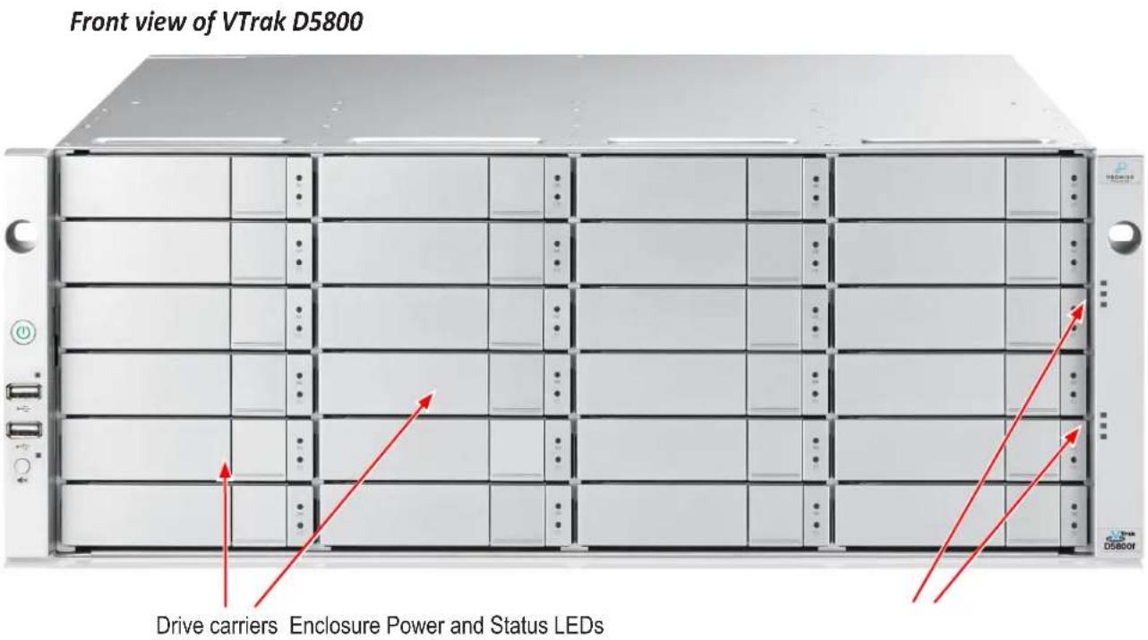
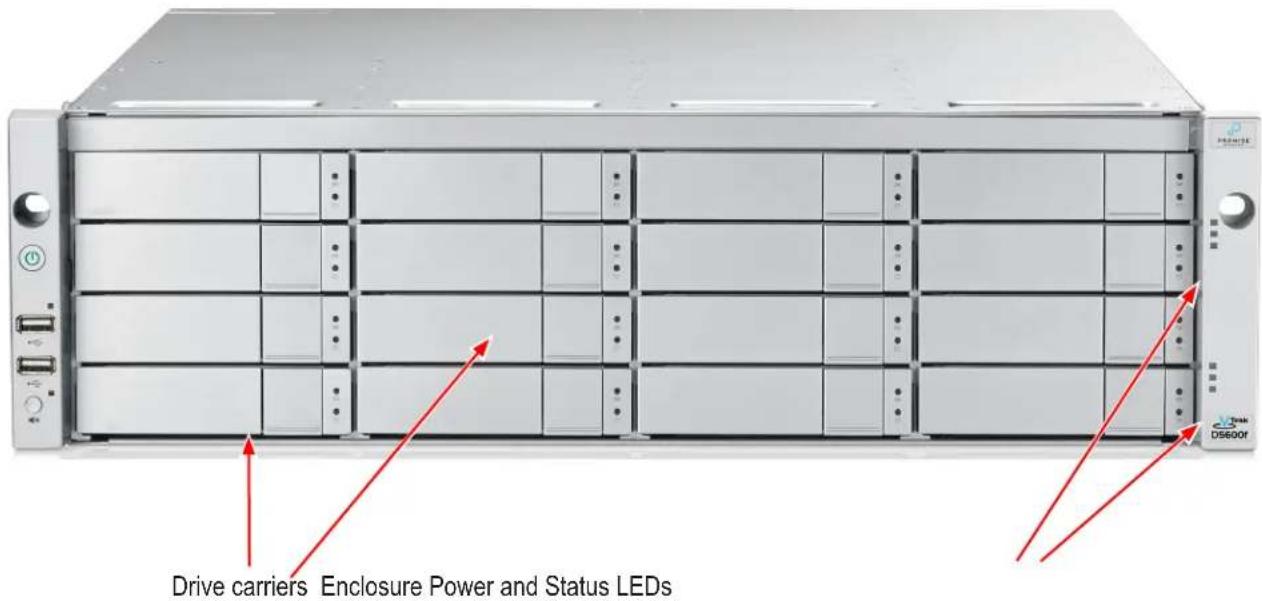
Front of VTrak D5800 and D5600
VTrak D5800/D5600 enclosures feature handles on each side used to secure the enclosure to an equipment rack.
Front view of VTrak D5600
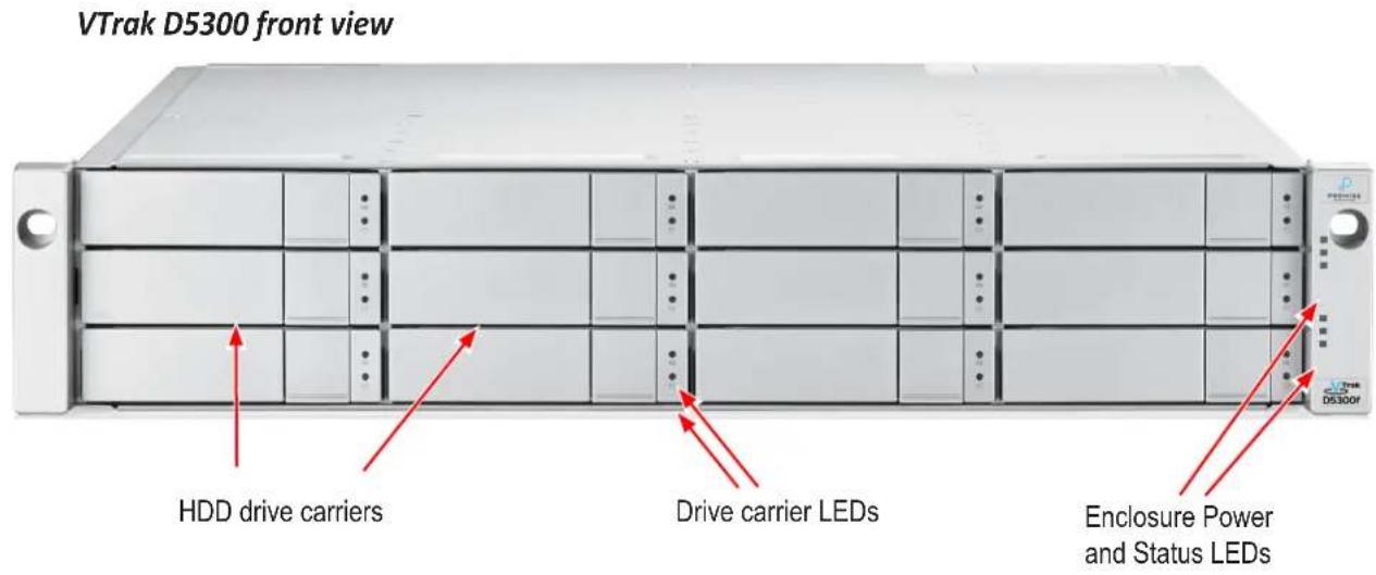
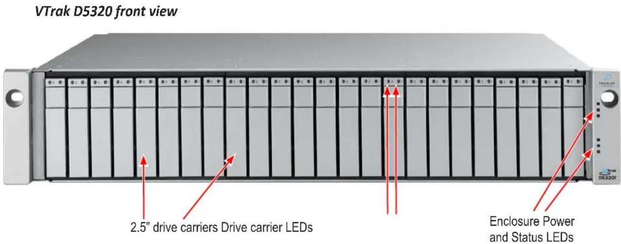
Front of VTrak D5300 and D5320
The front panel of VTrak D5000 enclosures provide access to storage disk drive carriers, a view of drive status LED indicators located on the front of each drive carrier, the LED indicators for system monitoring.
See the illustrations of the front view of each model below.
Back of VTrak D5800 and D5600
The rear of the VTrak D5000 Series enclosure provides access to the power supply units, which include the cooling fans, and the system controller(s).
Each controller has two RJ-45 Gigabit Ethernet ports used for management, an RS-232 serial management port using an RJ-11 connector, two 10 Gb/s iSCSI ports (SFP+ ports), two SAS Expansion ports for additional drive enclosures, and various LED indicators which are described below. In some markets, a special release of the VTrak D5000 controller includes four Fibre Channel data ports per controller using standard SFP sockets. The controllers pictured in this section display the Fibre Channel version.
Back view of VTrak D5800
Back view of VTrak D5600
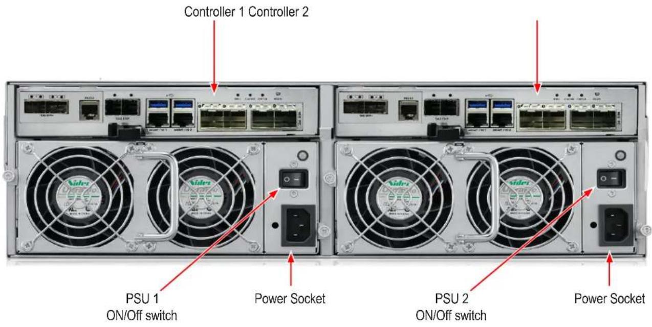
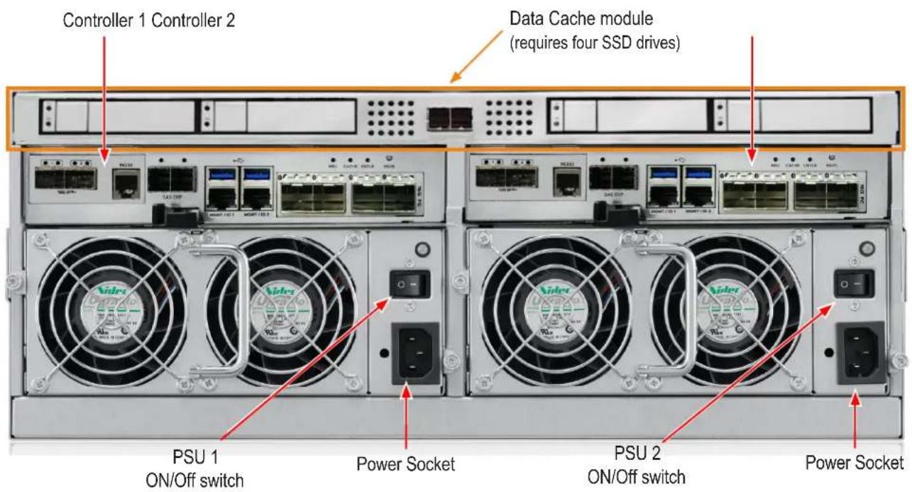
Back of VTrak D5300 and D5320
The rear of the VTrak D5000 Series enclosure provides access to the power supply units, which include the cooling fans, and the system controller(s).
Each controller has two RJ-45 Gigabit Ethernet ports used for management, an RS-232 serial management port using an RJ-11 connector, four Fibre Channel data ports per controller using standard SFP sockets, two 10 Gb/s iSCSI ports (SFP+ ports), two SAS Expansion port for additional drive enclosures, and various LED indicators which are described below.
VTrak D5300 and VTrak D5320 rear view
WARRANTY AND SUPPORT
WARRANTY
- Three year complete system limited warranty
- Battery Backup Unit has a one year limited warranty
- Optional 2-year extended warranty
- Optional onsite parts replacement program
Promise Technology, Inc. ("Promise") warrants that for three (3) years from the time of the delivery of the product to the original end user except for one (1) year warranty on the battery backup unit:
a) the product will conform to Promise's specifications;
b) the product will be free from defects in material and workmanship under normal use and service.
This warranty:
a) applies only to products which are new and in cartons on the date of purchase;
b) is not transferable;
c) is valid only when accompanied by a copy of the original purchase invoice;
d) is not valid on spare parts.
This warranty shall not apply to defects resulting from:
a) improper or inadequate maintenance, or unauthorized modification(s), performed by the end user;
b) operation outside the environmental specifications for the product;
c) accident, misuse, negligence, misapplication, abuse, natural or personal disaster, or maintenance by anyone other than a Promise or a Promise authorized service center.
HARDWARE INSTALLATION
This chapter presents basic information on unpacking the VTrak D5000 Series enclosure and mounting it in an equipment rack, making the connections for data and management paths and connecting the power. It also describes how to power on the system and what to look for while it is powering up.
The main sections in Hardware Setup include the following:
- Unpacking
- Mounting the VTrak enclosure in a rack
• Installing Physical Drives
• Making Management Connections - Connecting the Power
- Power on
Depending on the details of your order, the VTrak D5000 Series enclosure might be shipped with hard drives installed, or it might require that you install hard drives. The section “Installing Physical Drives” on page 22 provides instruction for installing hard disks.
Unpacking
Packing List
The VTrak D5000 Series box contains the following items:
- VTrak D5000 Unit
• One Quick Start Guide printed - Sliding rail assembly for rack mounting
• DB9-to-RJ11 serial data cable

Warning
The electronic components within the VTrak enclosure are sensitive to damage from Electro-Static Discharge (ESD). Observe appropriate precautions at all times when handling the VTrak or its subassemblies.

Warning
Two persons are needed to safely place the unit onto the rails.
DO NOT lift the unit by the handles
Mounting the VTrak enclosure in a rack
This section provides instructions for installing the VTrak D5000 Series enclosure into a rack

Caution
To lighten the enclosure, remove the power supplies, and remove all hard drive carriers. Replace the power supplies and drive carriers after the unit is mounted in your rack.

Cautions
- Do not populate any unit with hard drives until it has been securely installed in the rack.
- At least two persons are required to safely lift, place, and attach the unit into a rack system.
- Do not lift or move the unit by the handles, power supplies or the controller units. Hold the system itself.
- Do not install the unit into a rack without rails to support the system.
- Only a qualified technician who is familiar with the installation procedure should mount and install the unit.
- Mount the rails to the rack using the appropriate screws and nuts, fully tightened, at each end of the rail.
- Do not load the rails unless they are installed with screws as instructed.
- The rails available for the PROMISE VTrak unit are designed to safely support that PROMISE VTrak unit when properly installed. Additional loading on the rails is at the customer's risk.
- PROMISE Technology, Inc. cannot guarantee that the mounting rails will support your PROMISE VTrak unit unless you install them as instructed.
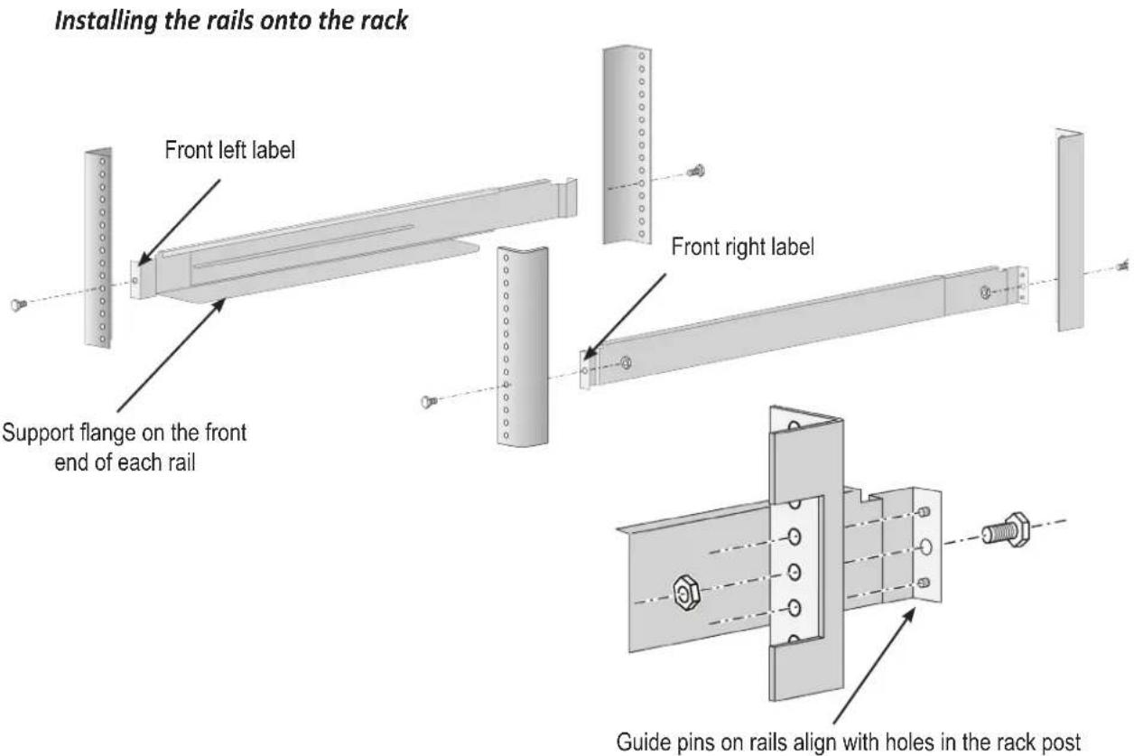
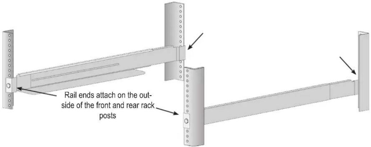
To install the VTrak into a rack with the supplied mounting rails:
- Check the fit of the mounting rails in your rack system.
-
Adjust the length of the mounting rails as needed.
-
The rear rail slides inside the front rail. The rails are composed of two sliding sections and do not require adjusting screws.
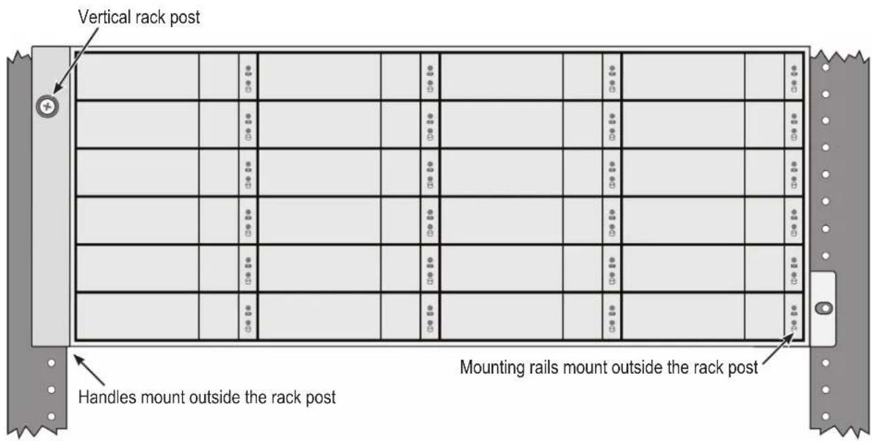
• The front-left and front-right mounting rail ends are labeled. - Be sure the front rail support is on the bottom facing inward.
- All rail ends, front and rear, attach at the outside of the rack posts.
- The guide pins at the rail ends align with the holes in the rack posts.
- Use the attaching screws and nuts from your rack system. Tighten the screws and nuts according to instructions for your rack system.
Rail ends attach to the outside of each post
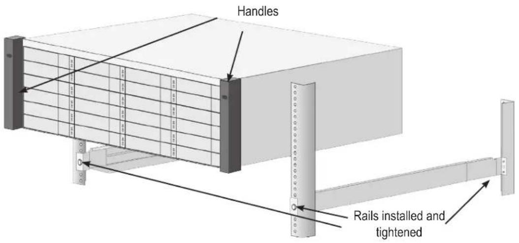
-
Place the VTrak onto the rails.
-
At least two persons are required to safely lift the system.
- Lift the VTrak itself. Do not lift the system by its brackets.

Warning
Two persons are needed to safely place the unit onto the rails.
DO NOT lift the unit by the handles
Placing the VTrak system onto the rack rails
- Secure the enclosure to the rack.
- Use screws and nuts to lock the unit in to place in the rack.
Secure to rack
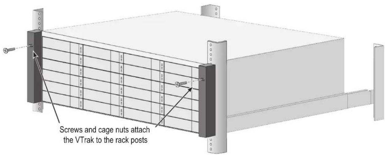
System installed in rack
Mounting the VTrak D5300/J5320
To install the 2U VTrak enclosure into a rack with the supplied mounting rails:
- Determine what height to place the 2U enclosure in the rack, then place the right and left rack rails at the same height on in the right and left rack position. Choose the mounting holes accordingly for your rack system. Consult the documentation for your rack if you are unsure which holes to use. Note that three holes are required on each front post, the uppermost of the three to be used for the nuts to anchor the enclosure to the rack posts.
Determine position for rack rails
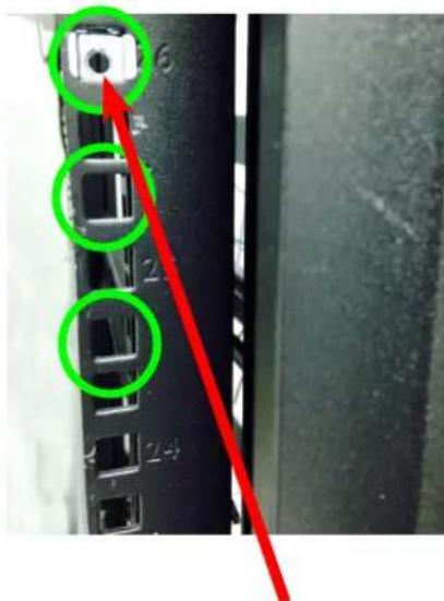
Insert nut in each front post
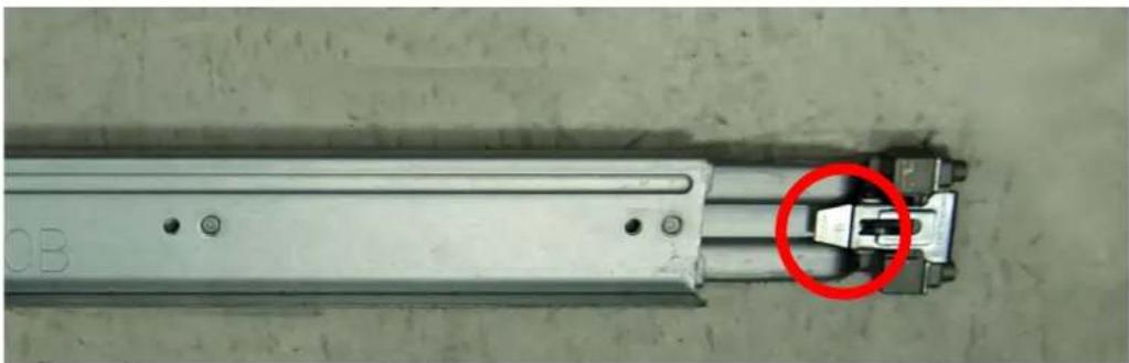
Notice that each end of the sliding rails have a lever to operate the lock mechanism that grips the rack post.
Lock release lever (back left)
natural_image
Close-up of a metallic mechanical component with a red circle highlighting a small feature, no visible text or symbols.Press lever to release lock (front right)
natural_image
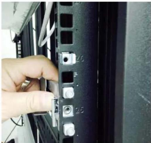
Close-up of a hand inserting a small component into a server rack with labeled pins (no text or symbols visible)- Secure the rails to the rack posts. Make sure the rack rails are properly oriented in the rack.
To set the rails into the rack posts and secure the rails, follow these steps:
a. Press the spring lock then insert the studs into the selected square holes on the rack post.
b. Press the spring lock on the other end of the rail and insert the studs into the selected mounting hole on the rack post. If necessary, extend the rail to reach the post.
c. Use the rail screws to anchor the rack rail to the post.
d. Make sure the rack rail is aligned, secure, stable and in the correct place.
e. Perform steps a through c above for the other rail.
f. Make sure the rack rails are aligned, secure, stable and in place. See figure below.
Back left rail secured to post
natural_image
Close-up of a black server rack with metal buttons and connectors, no visible text or symbols-
Secure the enclosure to the rack.
-
Use screws to lock the unit in to place in the rack.
- Use the attaching screws that came with the mounting hardware.
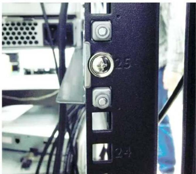
Insert screws on each side of the front of the enclosure to secure it to the rack posts
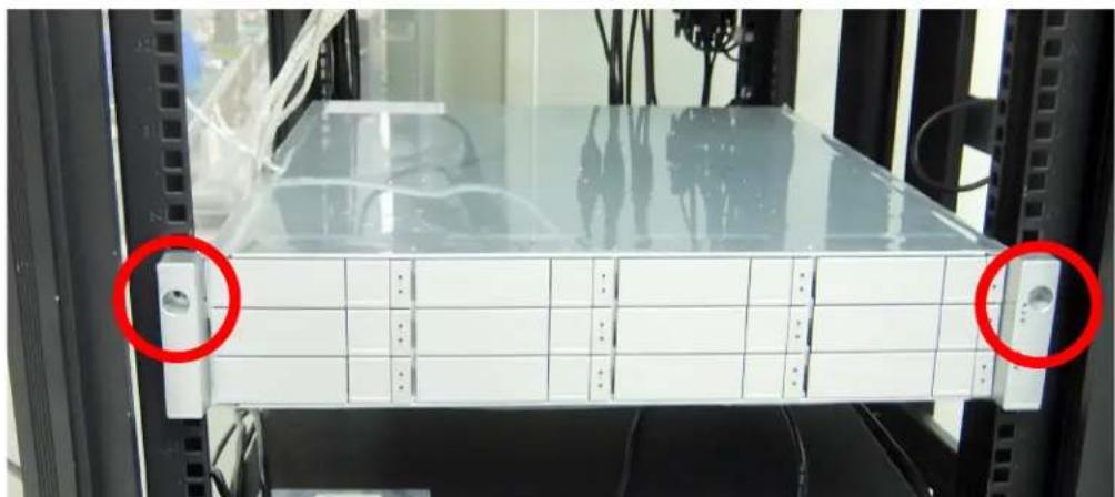
natural_image
Front view of a server rack unit with two red-circled ports, no visible text or symbols on the panel itself.Installing Physical Drives
The VTrak D5000 Series subsystems support:
- SAS hard disks
- SATA hard disks (SATA drives require use of an adapter)
• 3.5-inch hard disk drives for VTrak D5800, VTrak D5600, and VTrak D5300.
• 2.5-inch disk drives for VTrak D5320
For a list of supported physical drives, download the latest compatibility list from the PROMISE
http://www.promise.com/support/.
Number of Drives Required
The table below shows the number of drives required for each RAID level
| Level | Number of Drives | Level | Number | of Drives |
| RAID 0 | 1 or more | RAID 6 | 4 to 32 | |
| RAID 1 | 2 only | RAID 10 | 4 or more* | |
| RAID 5 | 3 to 32 | RAID 50 | 6 or more | |
| RAID 60 | 8 or more |
*Must be an even number of drives.

Caution
The VTrak D5000 Series supports disk drive hot-swapping. To avoid hand contact with an electrical hazard, do not remove more than one drive carrier a time.
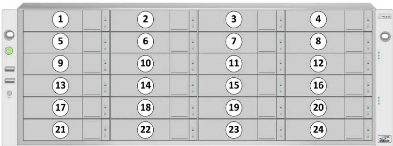
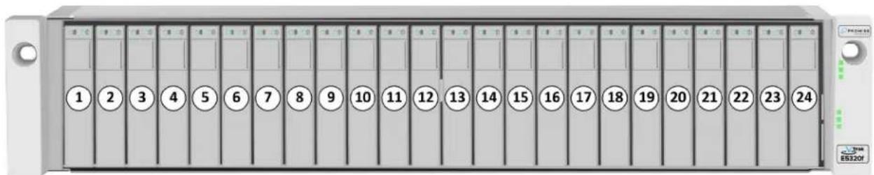
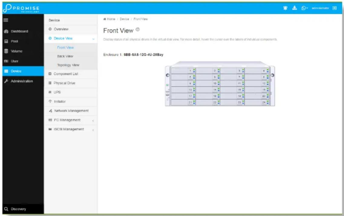
Drive Slot Numbering
You can install any suitable disk drive into any slot in the enclosure. The diagrams below shows how drive slots are numbered. Slot numbering is reflected in the WebPAM PROe and CLI user interfaces.
Be sure to install all of the drive carriers into the VTrak D5000 enclosure to ensure proper airflow, even if you do not populate all the carriers with physical drives.
Drive slot numbering on VTrak D5800
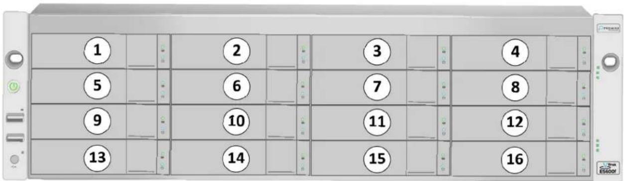
Drive slot numbering on VTrak D5600
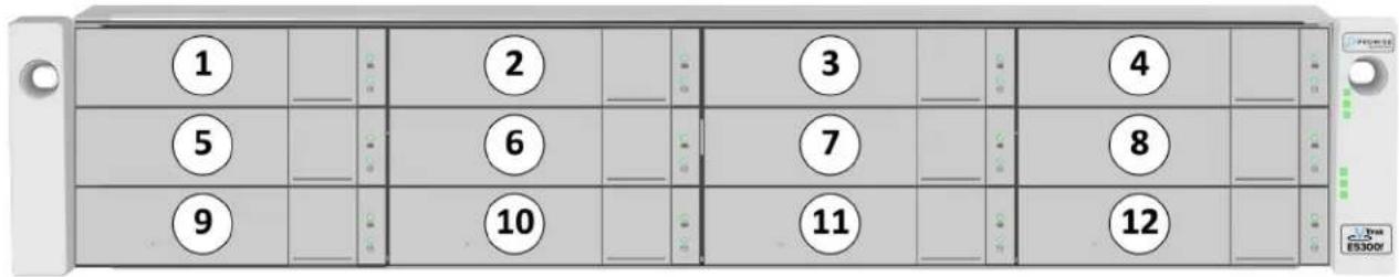
Drive slot numbering on VTrak D5300
Drive slot numbering on VTrak D5320
Installing Your Drives
The drive carrier accommodates 2.5-inch and 3.5-inch drives.
The VTrak D5000 does support use of SATA drives (SATA drives require use of an adapter), but SAS drives are recommended.
Follow instructions on the next page to install drives in the VTrak D5300, VTrak D5600 and VTrak D5800.

Cautions
Swing open the drive carrier handle before you insert the drive carrier into the enclosure.
To avoid hand contact with an electrical hazard, remove only one drive carrier a time.

Important
SATA drives require a SAS-to-SATA adapter, available from PROMISE Technology at http://www.promise.com/
SAS drives do not require adapters.
-
Press the drive carrier release button.
-
Grasp the front and gently pull the empty drive carrier out of the enclosure.
Drive carrier front view

natural_image
Simple diagram of a server rack with indicator lights and a red arrow pointing to the front panel (no text or symbols)Disk carrier release button
-
If you are installing SATA drives, attach a SAS-to-SATA adapter onto the power and IO connectors of each drive.
-
Carefully lay the drive into the carrier with the power and IO connectors facing away from the carrier handle.
-
Position the drive in the carrier so the mounting holes line up.
• 2.5-inch drive mounting screws go through the bottom of the carrier.
- SAS-to-SATA adapter mounting screws go through the bottom of the carrier.
• 3.5-inch drive mounting screws go through the sides of the carrier.
- Insert the screws through the proper holes in the carrier and into the drive or adapter.
• Use the screws supplied with the shipment or the SAS-to-SATA adapter.
• Install four screws per drive.
• Install two screws per adapter.
- Snug each screw. Be careful not to over tighten.
- With the drive carrier handle in open position, gently slide the drive carrier into the enclosure.

Important
Press the release button to push the drive carrier into position.
Proper drive installation ensures adequate grounding and minimizes vibration. Always attach the drive to the carrier with four screws.
2.5-inch Hard Disk Drives
The VTrak D5320 features 24 drive carriers designed to fit 2.5" drives. Notice that the carriers are oriented vertically, with the carrier release button at the top. The lever mechanism to remove the carrier from the drive bay works exactly the same as the 3.5" carriers, except they are positioned vertically rather than horizontally.

Caution
Swing open the drive carrier handle before you insert the drive carrier into the enclosure.
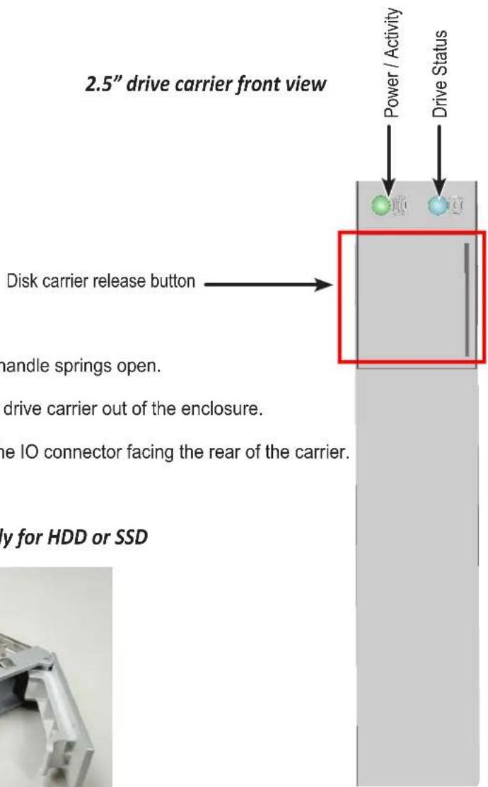
- Press the drive carrier release button. The handle springs open.
- Grasp the handle and gently pull the empty drive carrier out of the enclosure.
- Carefully lay the drive into the carrier with the IO connector facing the rear of the carrier.
Empty 2.5" drive carrier front ready for HDD or SSD

natural_image
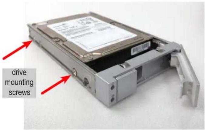
Metallic mechanical component with bracket and mounting holes (no text or symbols visible)- Position the drive in the carrier so the mounting holes line up.
- Insert the screws through the proper holes in the carrier and into the drive or adapter.
• Install four screws per drive.
- Snug each screw. Be careful not to over tighten.
2.5" drive carrier with HDD installed, front view
2.5" drive carrier with HDD, 'left' side with HDD undercarriage exposed
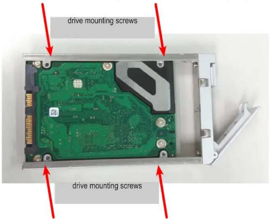
- With the drive carrier handle in open position, gently slide the drive carrier into the enclosure. The drive carrier should be oriented so the the "top" of the 2.5" HDD is on the right, and the "bottom" of the HDD is on the left. The LED indicators will be at the top.
Making Management Connections
There are two methods to establish a management connection, Network and Serial connection. For the initial setup, it is necessary to establish the network management connection; use the MGMT 1 port on both controllers for system management. The VTrak D5000 Series also features a Serial management port for system management using a terminal emulation program and the VTrak D5000 Command Line Interface (CLI). The hardware connections for both methods are described in this section.
VTrak D5000 Series controller Management and IO ports
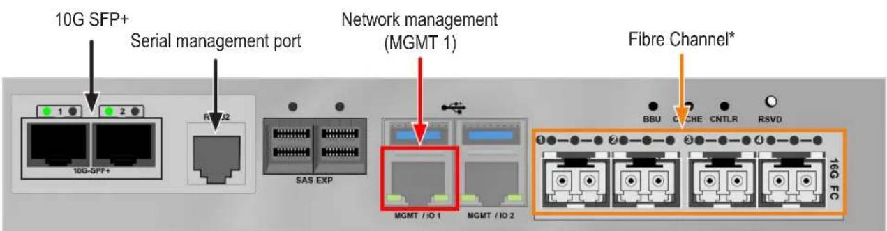
* Fibre Channel might not be available in all markets.
Network management connection
Each VTrak D5000 Series controller has two 1000BASE-T Ethernet ports. Port MGMT 1 (left most 1000BASE-T port) is used for system management.
To establish the management path network connection:
- Attach one end of an Ethernet cable to the network connector or standard NIC in the Host PC, attach the other end of the Ethernet cable to a port on a standard network switch.
- Attach one end of an Ethernet cable to the same network switch and attach the other end to the MGMT 1 port on controller 1.
- If the subsystem is dual controller, connect one end of an Ethernet cable to the same network switch and attach the other end to the MGMT 1 on controller 2.

Note
The RJ-45 network management ports on a VTrak D5000 Series subsystem share the same Virtual IP address. The default Virtual IP address, 10.0.0.1, applies to the left most RJ-45 network port (MGMT 1) on both controllers. If you change the Virtual IP address, the change applies to both network management ports.
Serial management connection
Serial communication enables any computer that has an available serial port and terminal emulation application to access the VTrak Command Line Interface (CLI) to set up a network connection. The VTrak package includes one RJ11-to-DB9 serial data cable for each controller.
To set up a serial cable connection:
- Attach the RJ-11 end of the serial data cable to the RJ-11 serial connector on one of the RAID controllers.
- Attach the DB9 end of the serial data cable to a serial port on the host PC or server.
Controller serial interface
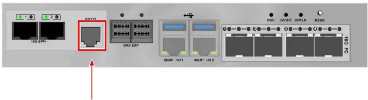
Serial port (RJ-11) Use the DB9 to RJ-11 adapter to connect
Making Data Connections
Each VTrak D5000 controller supports two Fiber Optic (SFP+) 10G connections for data. Controllers available in some markets also support four Fibre Channel connections (up to 16G). Follow the instructions below for the type of data connection you are setting up.
Fiber Optic (SFP+) data path
The Fiber Optic data network for the VTrak D5000 controller requires the following items:
• An SFP+ connection in each host PC or server
• An SFP+ transceiver for every SFP+ port in the connection (subsystem, switch, HBA)
• An SFP+ switch (not required for direct attached connection)
• Fiber Optic cabling (LC/LC 62.5/125μm MMF)
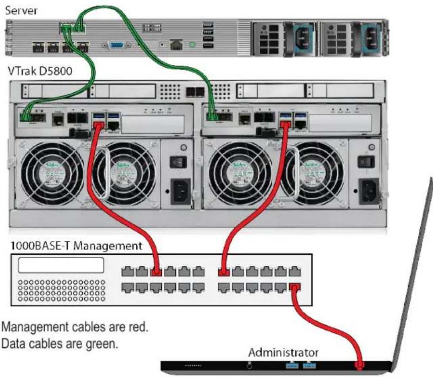
Management and Fiber Optic SAN connections

SFP+ Fiber Optic SAN connections
For the Fiber Optic storage network:
-
Connect a Fibre Optic cables between the Fibre Optic ports on the server and the Fibre Optic ports on the SFP+ switch.
-
Connect Fiber Optic cables between the Fiber Optic port on the VTrak D5000 controller and a Fiber Optic port on a SFP+ switch.
If you have multiple VTrak D5000 subsystems, host PCs or servers, repeat the steps as required.
Management and Fiber Optic DAS connections
SFP+ Fiber Optic DAS connections
For the Fiber Optic Direct Attached Storage:
-
Connect Fiber Optic cable to the Fiber Optic port on the host PC or server.
-
Connect the other end of the Fiber Optic cables to the SFP+ Fiber Optic port on the VTrak D5000 controller.
Fibre Channel SAN data path
The Fibre Channel data network for the VTrak D5000 controllers requires the following items:
• A Fibre Channel connection in each host PC or server
• An SFP transceiver for every SFP (Fibre Channel) port in the connection (subsystem, switch, HBA)
• A Fiber Channel switch (not required for direct attached connection)
- Fiber Optic cabling
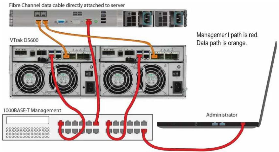
Management and Fiber Channel SAN data connections
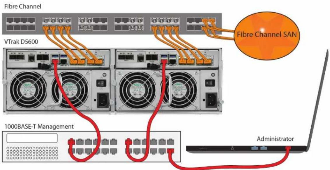
Management cables are red.
Data cables are orange.

Important
For a list of tested HBAs, switches, and SFP transceivers, download the latest compatibility list from PROMISE support:
http://www.promise.com/support
Fibre Channel SAN connections
For the Fibre Channel storage area network (SAN):
- For servers equipped with Fibre Channel HBA cards, connect Fiber Optic cables between the Fibre Channel ports in both host PCs or servers and the ports on a Fibre Channel network switch.
- Connect Fiber Optic cables between the Fibre Channel port on the VTrak D5000 controllers and a Fibre Channel port on a Fibre Channel switch or Fibre Channel capable switch (SFP). If you have multiple VTrak D5000 subsystems, host PCs or servers, repeat the steps as required.
Fiber Channel DAS data path
The Fibre Channel data network for the VTrak D5000 controllers requires the following items:
• A Fibre Channel connection in each host PC or server
• An Fibre Channel transceiver for each connected port on the subsystem
• Fiber Optic cabling (LC/LC 62.5/125μm MMF)
Direct Attached Storage (DAS) Fibre Channel connection
Fibre Channel DAS connections
For Fibre Channel direct attached storage (DAS):
- For each attached server or host PC, connect Fiber Optic cable to the Fibre Channel port on the host PC or server.
- Connect the other end of the Fiber Optic cable to a Fibre Channel port on one of the VTrak D5000 controllers.
It is recommended to use two Fibre Channel connections from the host computer to the VTrak D5000 so that there is a physical path from the host to each of the VTrak D5000's controller's. This improves performance and provides redundancy.
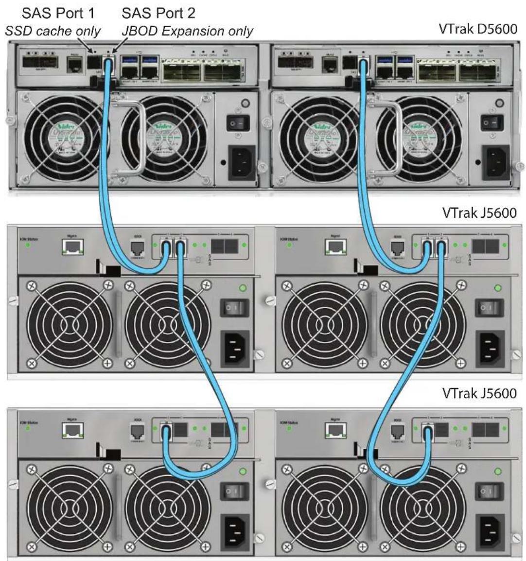
VTrak D5000 with JBOD Expansion
The setup description below references the illustration "VTrak D5600 with VTrak J5600 JBOD expansion connections" on the next page.
To add VTrak J5000 Series units:
- Connect the SAS expansion port (SAS port to the right) on the left controller of the RAID subsystem to the SAS port 1 on the left I/O module of the first VTrak J5000 unit.
- Connect the SAS expansion port (SAS port to the right) on the right controller of the RAID subsystem to the SAS data port 1 on the right I/O module of the first VTrak J5000 unit.
- Connect the SAS data port 2 on left I/O module of the first VTrak J5000 unit to the SAS data port 1 on the left I/O module of the second VTrak J5000 unit.
- Connect the SAS data port 2 on right I/O module of the first VTrak J5000 unit to the SAS data port 1 on the right I/O module of the second VTrak J5000 unit.
- Connect any remaining VTrak J5000 units in the same manner.
Keep in mind the following points:
- Keep your data paths organized to ensure redundancy.
- JBOD expansion supports up to nine VTrak J5000 units.

Important
Power on the JBOD units first, when you are ready to power on the enclosures.
Read the VTrak J5000 Series Product Manual for information on the VTrak J5000 Series enclosures.
VTrak D5600 with VTrak J5600 JBOD expansion connections
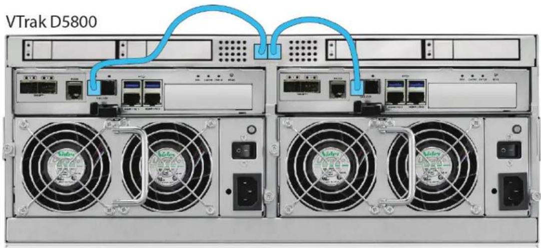
VTrak D5800 SSD Data Cache Module
The VTrak D5800 includes a module used for an SSD data cache. If you will use this, make sure to install the SSD drives and connect the SAS cables before you configure the storage.
Note that the disk carrier hardware is identical to the 2.5" disk carriers used for the VTrak D5320. Install identical SSD drives in all four disk carriers. Go to www.promise.com for a list of compatible SSD drives.
- Connect the left most SAS port on the data cache module to the left most SAS port on the left controller.
- Connect the right most SAS port on the data cache module to the left most SAS port on the right controller.
SAS cable connections for SSD data cache on VTrak D5800

Important Notice for VTrak D5800
In order to use the optional SSD data cache, it is necessary to install four SSD drives and connect the SSD data cache module to both controllers via SAS cable. This must be done BEFORE storage configuration.
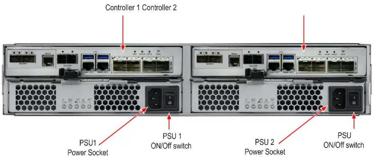
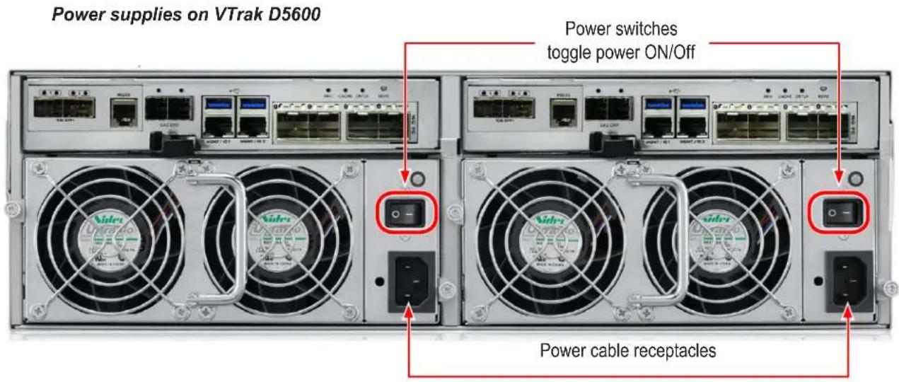
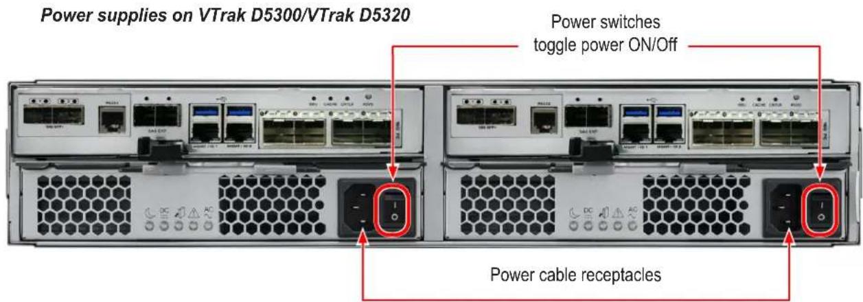
Connecting the Power
VTrak D5000 Series enclosures are equipped with two power supplies for each unit. All VTrak models feature an ON/OFF switch on the power supply unit (PSU). Connect both power supplies to a suitable power source.
The 2U VTrak D5300/D5320 will power on when the power switch on each power supply is in the On position. See illustration below.
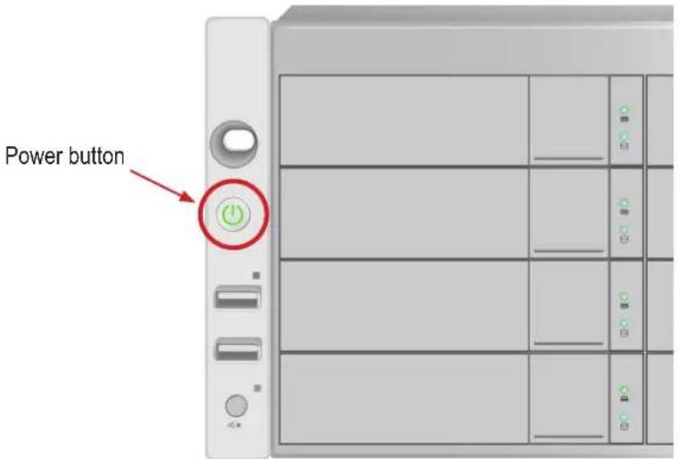
The 3U VTrak D5600 and 4U VTrak D5800 have a power button on the front used to power on the subsystem.
Power on
With the power cables connected, the system can now be powered on. The power supply modules include the cooling fans that cool the enclosure. Both power supplies should be powered up when starting the system. Make sure the power switch on each power supply is in the On position. Note that this will power on the VTrak D5300 and VTrak D5320.
To power on the VTrak D5600 or VTrak D5800 subsystem, first switch on the power supplies in the back of the unit, then press the power button on the front left bracket facing (see illustration below). Observe the LEDs on the right front bracket facing.

Important
If you have a SAN, DAS, or Cascade with JBOD Expansion, always power on the JBOD subsystems first.
Power button on front left of VTrak D5600/D5800
Front LED Behavior
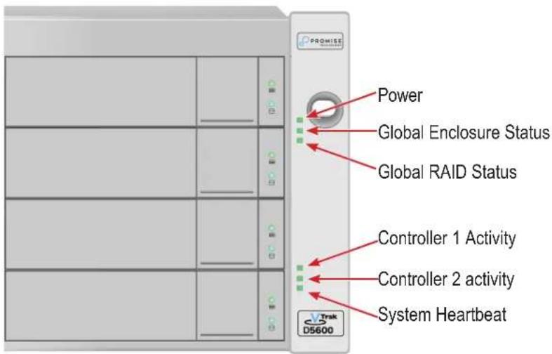
When boot-up is finished and the subsystem is functioning normally:
• Power, FRU and Logical Drive LEDs display Green continuously
- Controller Activity LED flashes Green when there is controller activity.
- System Heartbeat LED blinks Green once per second for five seconds, then goes dark for ten secondes, then repeats the same pattern.
Also on the front panel, there are two LEDs on each drive carrier. These report the presence of power and a physical drive, and the current condition of the drive. See table on next page for complete description of LEDs on front right of VTrak D5600/D5800.
LED indicators on front right of VTrak D5600/D5800 enclosure
VTrak D5600/D5800 front right LED Behavior After Boot Up
| State | Power | Global Enclosure | Global RAID | Controller Activity | Controller Heartbeat |
| Dark | No power No power — | Unit is off, or controller is not present or FC is not cable connected | — | ||
| Steady Green | Normal Normal Normal | Unit is up, controller is present and running, at least one FC cable is connected and a link is established. | — | ||
| Blinking Green | — — — — Norma ** | ||||
| Flashing Green | — — — Activity — | ||||
| Amber | — Problem* | Critical — — | |||
| Red | — Failure* Offline | — — | |||
* Check the LEDs on the back of the VTrak enclosure (controllers and PSUs).
** Blinks green once per second for two seconds for dual controller enclosure; blinks every four seconds for single controller enclosure.
Disk Carrier LEDs
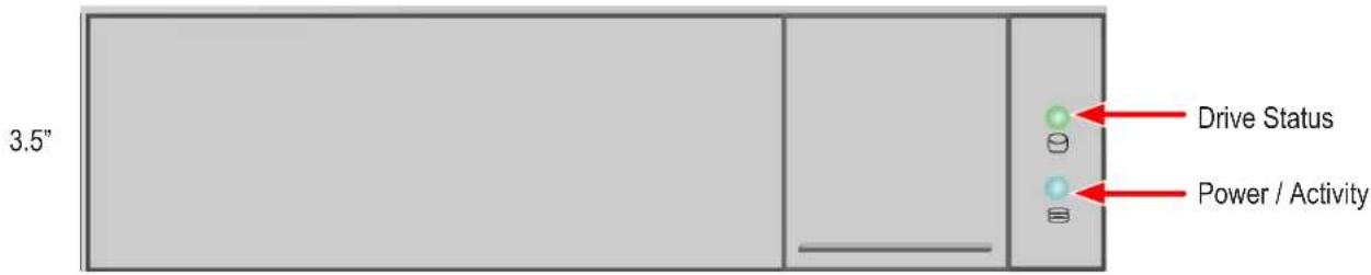
The VTrak spins up hard disk drives sequentially to minimize power draw during start-up. After a few moments:

• The Power/Activity LED displays blue when a physical drive is present.
- The Drive Status LED displays green when the physical drive is configured as a member of a disk array or as a spare. When the physical drive is unconfigured, the LED is dark.
Steady means the LED is on.
Blinking means a regular on/off pattern.
Flashing means intermittent and irregular on/off pattern.
Drive Status LED Behavior After Boot Up
| State | Power/Activity Drive Status |
| Dark | No drive in carrier Drive is not configured |
| Steady Blue | Drive in carrier — |
| Flashing Blue | Activity on drive — |
| Steady Green | — Drive is configured |
| Blinking Green | — Locator feature |
| Amber | — Drive is rebuilding |
| Red | — Drive error of failure |
* Configured means the physical drive either belongs to an array or it is assigned as a spare drive.
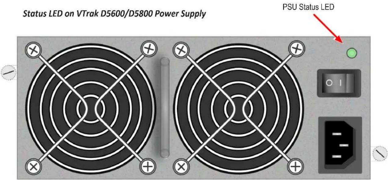
VTrak D5600 / VTrak D5800 Power Supply LEDs
The LEDs on the rear panel of the VTrak D5600 and VTrak D5800 include a single status LED on each power supply. These PSU status LED will light green to indicate normal operation. A red LED indicates a problem or unit failure.
VTrak D5300 / VTrak D5320 Power Supply LEDs
The power supplies for the VTrak D5300 and VTrak D5320 have five LED indicators on each unit. See the table below for PSU LED behavior.
Power supply LED indicators on VTrak D5300/D5320
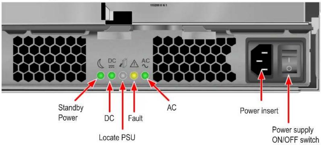
VTrak D5300/D5320 Power Supply LEDs
| LED | Description |
| Standby Power | This indicates the standby power status. If the standby power is on and the power switch is off, the LED lights green. If the standby power is on and the power switch is on, then the LED will be off. |
| DC | This indicates if the power supply is properly inserted into the enclosure. The LED lights green when the power supply is properly inserted and the power supply is switch on. It is off if the power supply is not properly inserted, or when the power supply is switched off. |
| Fault | This indicates the overall health status of the power supply. When the power supply is functioning normally and no problems are detected, it will be off. If a problem with the power supply is detected, it light amber.Note that this LED blinks once when the power supply is switched on, then remains off unless there is a problem. |
| AC | This indicates that input power is present. When the power supply is switched on, it lights green if input power is available. It is off if power is not present and when the power supply is switched off. |
| Locate PSU | This flashes blue when using the Locate PSU function. |
Controller LEDs
When boot-up is finished and the VTrak D5000 subsystem is functioning normally:
• Controller status LEDs display green continuously.
- Ethernet LEDs display green or flash depending on your network connection.
• The FC, SAS, and Expansion LEDs display green or flash during port activity.
See table on next page for complete description of controller LEDs.
Controller LEDs
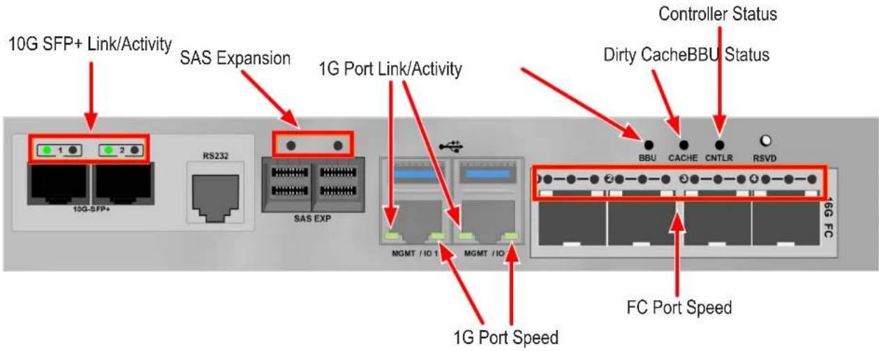
Controller LED Behavior
The table below describes behavior of the LED indicators on the VTrak D5000 Series controller.
| LED | Description |
| 10G SFP+ Link/Activity | Left LED: Solid green light indicates a link.Right LED: Flashing green light indicates activity. |
| SAS Expansion | One LED indicator for each SAS expansion port. These light green when connected, and flash green when there is activity. |
| 1G Port Link/Activity Speed | Left LED: Flashing light indicates activity.Right LED: Solid green light indicates a link. |
| Controller Status | This displays the current operational status of the controller. A steady (unblinking) green light indicates the controller is operational. This will blink green when using the controller locator feature. A blinking amber light indicates a problem. Steady red light indicates controller failure. A flashing red light means the controller is in Maintenance Mode (offline while in Maintenance Mode). |
| Dirty Cache | Lights steady amber if cache is dirty, meaning that the controller memory cache contains data, otherwise this is dark. This will blink green when using the controller locator feature. |
| Battery Status | This lights steady green when the battery status is healthy (normal). Red indicates the battery has failed. A steady amber light indicates there is not enough reserve power in the battery to backup cache memory if the power fails. |
| FC ports | See next page |
LED indicators for Fibre Channel ports, three LEDs for each FC port
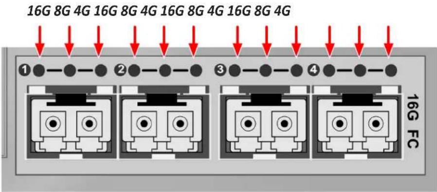
Fiber Channel Port LED behavior
| LEDs | Power on (Before Firmware Initialization) | Power on (After Firmware Initialization) | Firmware Fault | 4 Gbps Link Up/ ACT | 8 Gbps Link Up/ ACT | 16 Gbps Link Up/ ACT |
| Green LED (16 Gbps) | On Flash | Flash in sequence | Off Off | On/Flash when active | ||
| Green LED (8 Gbps) | Off | On/Flash when active | Off | |||
| Green LED (4 Gbps) | On/Flash when active | Off Off |
All Fibre Channel port LED indicators will be dark when the system is powered off. If all three indicators for a port flash simultaneously, then there is no SFP transceiver installed, or the wrong type of transceiver is installed, or the port is not connected.
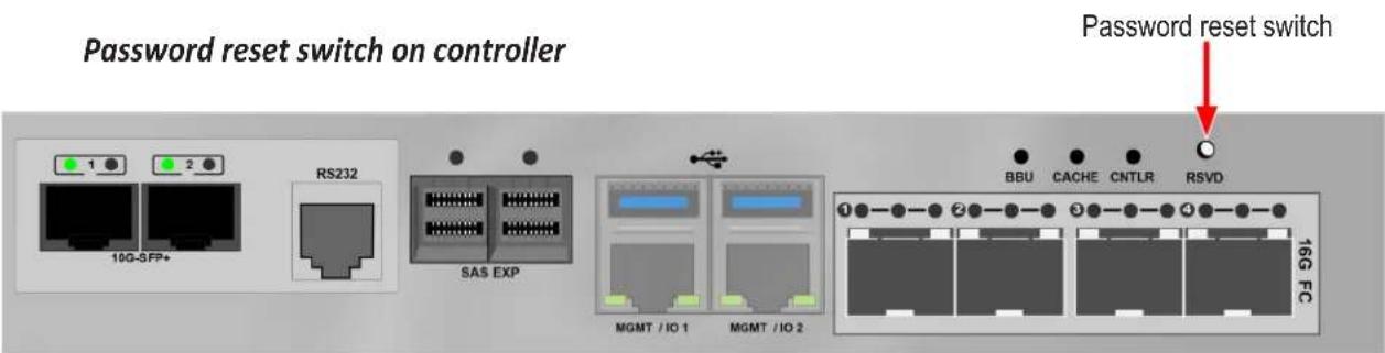
Resetting the Default Password
This feature resets the Administrator's password to the default factory setting, password. Use this feature when you have forgotten Administrator's password or a new Administrator has been appointed.
The reset applies to the Administrator's login for WebPAM PROe and the CLI. No other user passwords are affected.
To reset the Administrator's default password:
- Verify that the VTrak has fully booted.
- For one of the RAID controllers, locate the password reset switch. See illustration below.
- Insert a pin or a straightened paper clip into the opening and momentarily depress password reset switch.
You only need to press the reset switch on one RAID controller.
The next time the Administrator logs in, use the default password: password.

Important
PROMISE recommends that you change the Administrator's default password immediately after reset.
This chapter describes system configuration using WebPAM PROe. The information is presented in approximately the same order the links for the menus appear in the WebPAM PROe user interface. The menus, submenus and other configuration information includes the following:
- Logging into WebPAM PROe
• Viewing the Storage Network - Dashboard
- Creating a Shared Storage Pool
- Creating a Volume
LOGGING INTO WEBPAM PROE
- Launch your browser.
- In the browser address field, type in the virtual management port IP address of the VTrak D5000 subsystem.
Use the IP address you set in the CLI.
Note that WebPAM PROe requires a secure HTTP connection (i.e. https://). For example, if your VTrak D5000 has an IP address: 10.0.0.1 your entry looks like this: https://10.0.0.1
-
When the login screen appears:
-
Type administrator in the User Name field.
- Type password in the Password field.
- Click the Login button.
The User Name and Password are case sensitive.
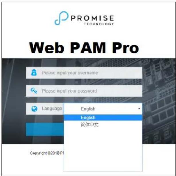
- Optional. Choose a display language from the drop-down menu.
WebPAM PROe displays in English and Simplified Chinese.
- Click the Login button.
After login, the WebPAM PROe main menu appears.
Choosing the Display Language
WebPAM PROe displays in multiple languages. You choose the display language when you log in.
If you are already logged in and you want to change the display language:
- Click Logout at the top right corner of the screen.
The Login screen appears.
- Click the Language drop-down menu and highlight the language you prefer.
Login language selection menu
-
Reenter your user name and password.
-
Click the Login button.
WebPAM PROe opens in the language you chose.
Perusing the Interface
The WebPAM PROe interface consists of a header and four tabs, each with specific functions.
- Header
Top right corner of the window:
- Event Notification
- Save Service Report – Saves a detailed report to your Host PC
• Name of logged-in user - Logout – Exits WebPAM PROe
Use the pulldown menu (small telephone icon) to see these links:
- Get Help – Accesses the Help Welcome screen
- About – Information about WebPAM PROe
- Contact Us – Technical support contact information
- Discovery tab (located in bottom left corner of WebPAM PROe window)
- Displays other PROMISE RAID systems on your network
- Enables direct login to other PROMISE RAID systems
The main information and configuration menus are as follows:
- Dashboard tab
- Subsystem Health quick summary
• Capacity Utilization summary
• Performance graphic summary
- Pool tab
- Create New Pool button (Setup Wizard)
- Pool List (including Extend or Delete existing pool)
- Cache (SSD cache configuration)
- Spare Drive (including create or delete spare drive)
- Volume tab
- Create New Volume button (Setup Wizard)
• Volume List (including Delete, Export, and Un-export)
• LUN Mapping & Masking - Periodic Snapshot
List continues on next page
- NAS Share tab
• Create New NAS Share
- NAS Share List
- Protocol
- Periodic Snapshot
- NAS Account tab
• NAS User (Create, delete, modify users)
- NAS Group
- Domain
- Device tab
- Device Overview (Device status and information summary, NTP settings, Date and time setting, Subsystem restart and shutdown)
• Device View (Front View, Back View, Topology) - Component List (Enclosure, Controller, Battery, Buzzer, summary and configuration)
• Physical Drive (Physical drive information summary, Physical drive settings) - UPS (summary and configuration)
- Initiator (summary delete, add initiator)
• Network Management (Virtual and physical port summary and configuration) - FC Management (Information and configuration for FC including: Node, Port, Statistics, Logged in devices, Devices on fabric, SFP)
- iSCSI Management (Information and configuration for iSCSI including: Target, Port, Session, Portal, iSNS, Trunk, Chap, Logged in devices)
- Administration tab
- Events
- Management User
- Service
• Performance Monitor - Image Version
- Firmware Update
- Background Activity
- Restore Factory Default
- Import/Export
- Product Registration
- Setup Wizard
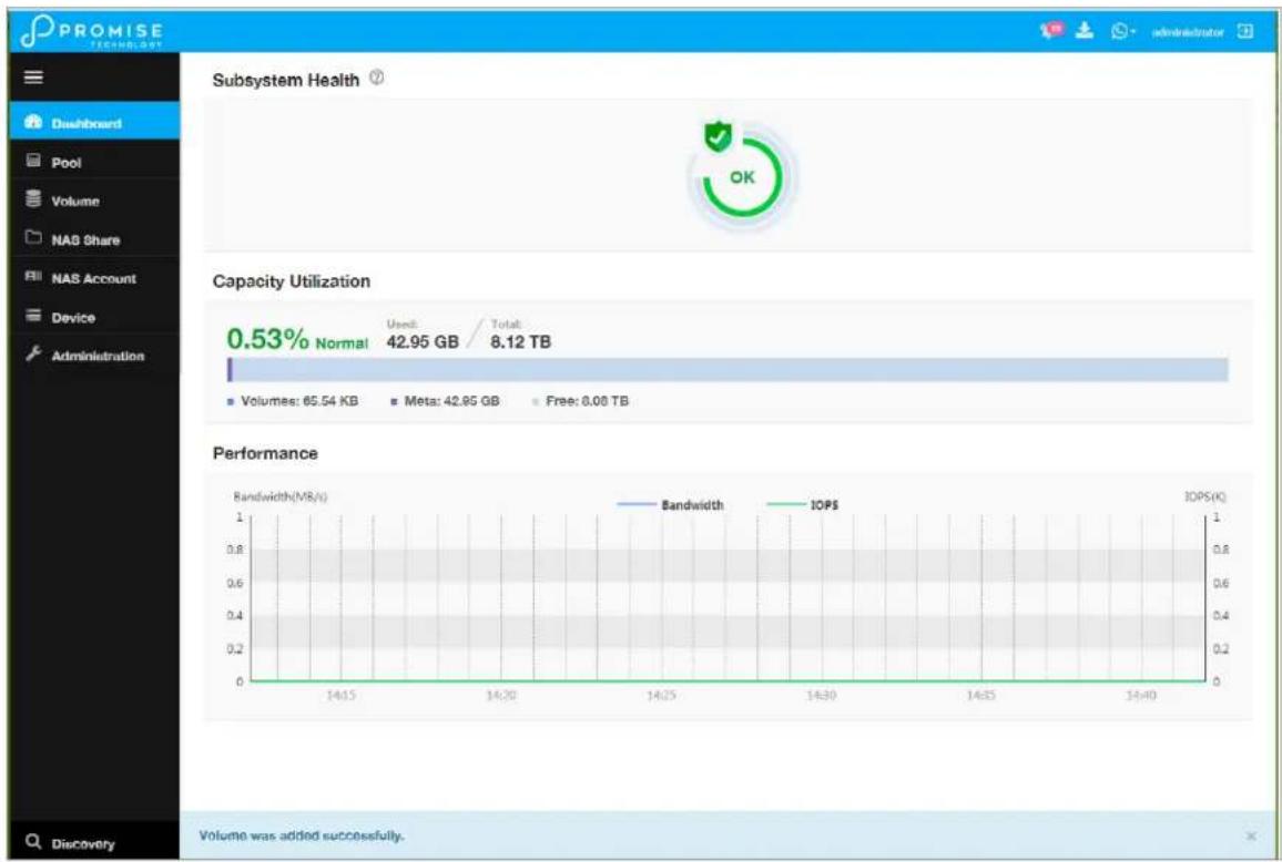
Web PAM PROe Main menu/Dashboard
bar_line
| Metric | Value | | :--- | :--- | | Subsystem Health (Usage) | 42.95 GB / 8.12 TB | | Capacity Utilization | 0.53% Normal | | Volumes | 65.54 KB | | Meta | 42.85 GB | | Free | 0.00 TB | | Bandwidth (MB/s) | 1.0 | | Bandwidth (IOPS) | 1.0 | | IOPS (K) | 1.0 | | Volume (W) | Added successfully. |Logging out of WebPAM PROe
There are two ways to log out of WebPAM PROe:
- Close your browser window
- Click the Logout icon in the upper right corner of the GUI
Clicking Logout brings you back to the Login Screen.
After logging out, you must enter your user name and password in order to log in again.
VIEWING THE STORAGE NETWORK
To view the other subsystems on your Storage Network, click the Discovery button at the left bottom edge of the WebPAM PROe window.
Discovery menu in Main menu
Logging onto a Subsystem
To log onto a subsystem in the list, click on the IP address of that subsystem.

Caution
The new subsystem displays in the same browser tab. Click your browser's back button to return to the original subsystem.
DASHBOARD
The Dashboard presents a quick system status overview, including graphs for storage capacity utilization, I/O performance and network bandwidth used.
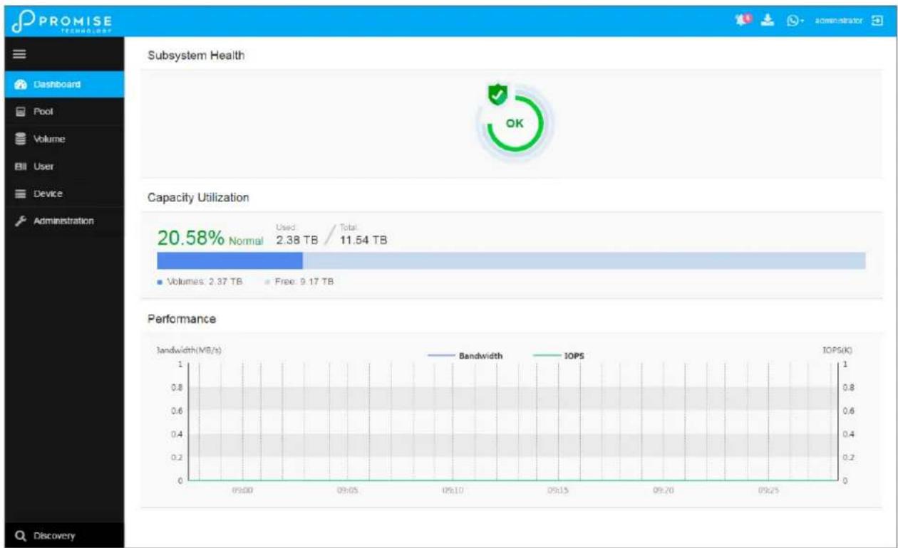
bar_line
| Metric | Value | |--------|-------| | Capacity Utilization | 20.58% Normal | | Volumes | 2.37 TB | | Bandwidth | 1.0 | | IOPS | 1.0 | | Bandwidth (MB/s) | 1.0 | | IOPS (kΩ) | 1.0 |Capacity Utilization
A graph and numerical list of total available storage capacity, used capacity, size of existing volumes, storage used for snapshots, and free capacity.
Performance
A graphic summary of Bandwidth in MB/s and I/Os per second
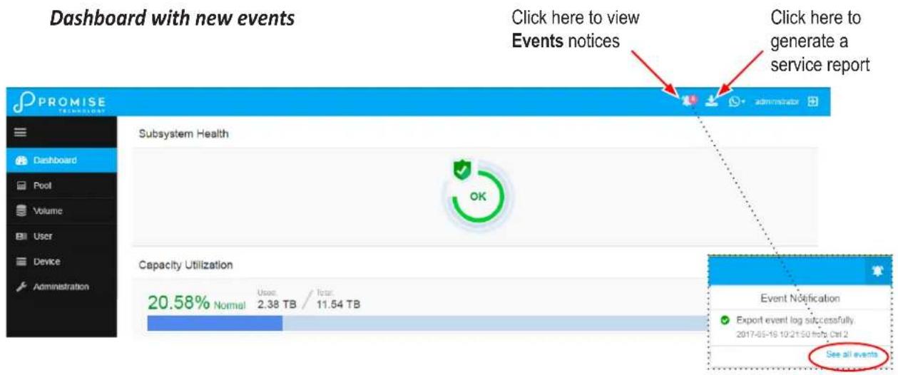
Generating a Service Report
A Service Report is a detailed report covering the configuration and status of all components in your RAID system. A support technician or field engineer might request a service report for the purpose of diagnosis and troubleshooting.
To save a Service Report file:
- Click the Generate Service Report in the Header (very top of the web interface, next to the Events/Alarm icon. It looks like a 'download' icon.).
Information for the report is gathered and compiled. This action takes up to a few minutes, depending on the report size of your RAID system - In the Save File dialog, click the Save button.
The report saves to your Host PC as a compressed HTML file. - Double-click the downloaded file to decompress it.
- Double-click the report to open it in your default browser.
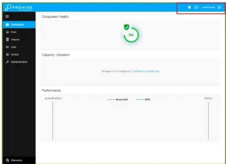
CREATING A SHARED STORAGE POOL
The first step for provisioning storage capacity to client systems is create a storage pool. The storage pool is a storage resource consisting of a number of hard disks in a RAID configuration.
After logging in, the Dashboard appears. Since the device is not yet configured, there will be little information in the Dashboard. The Dashboard is described in a later section once there is meaningful information to present.
To begin setting up the pool, you can click on the link in the middle of the menu, Storage is not configured. Click here to create one; or, click on the Pool menu icon in the left panel, then click the Create Pool button.
Dashboard
Create New Pool
In the Create New Pool menu, click to select the available hard disks you want to be in the pool, the selected disks become darker in color to indicate selection. Type a name used for the pool, then choose the remaining parameters:
• Media Type (HDD or SSD)
• RAID Level (RAID0, 1, 5, 6, 10, 50, and 60)
- Stripe Size (64 KB, 128 KB, 256 KB, 512 KB, and 1 MB)
• Sector Size (512 B, 1 KB, 2 KB, and 4 KB)
• Preferred Controller
Choose drives for new pool
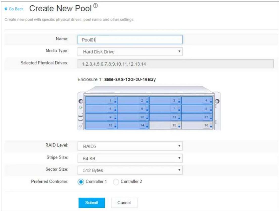
Click on the Submit button to create the pool.
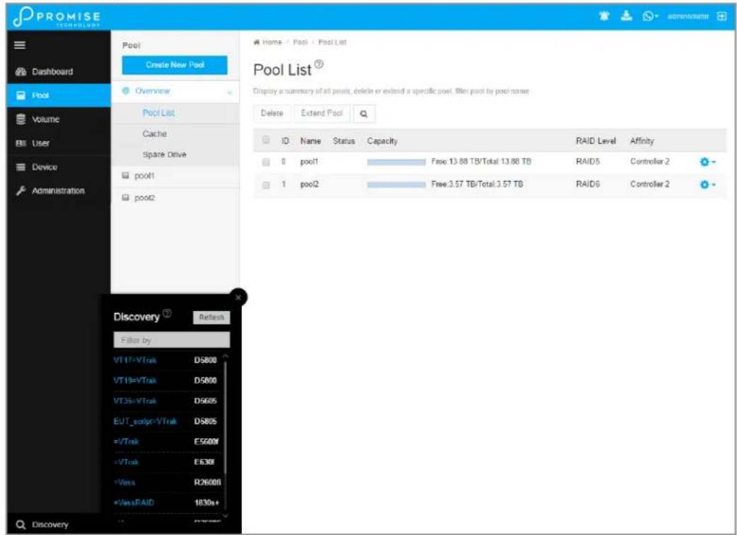
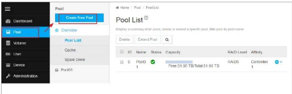
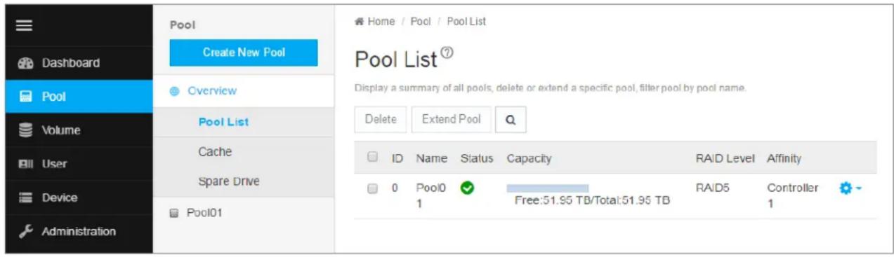
Pool List
Storage pools are listed in the Pool List after creation. Use this menu to delete or extend a pool. To view more detail, click on the gear icon for the pool and select the Detail option. Note that, except of the pool name and preferred controller, pool parameters cannot be edited once it has been created.
To extend a pool, select it in the list and click on the Extend button. The Extend menu appears. If you want to add JBOD units, the Extend Pool procedure is used to add JBODs.
To delete a pool, select it and click the Delete button. You will need to confirm that you want to delete the pool in a pop-up menu. Type “confirm” and click the Confirm button to remove the pool. The drives in that pool revert to unassigned available status.
View current shared pool configuration
Extending a Storage Pool with JBOD
A storage pool can be extended if there are physical disks available in the original enclosure, or in a VTrak J5000 JBOD connected via SAS cable to the VTrak D5000 head unit. If you plan to expand capacity using JBODs, it is necessary to use the Extend Pool process for each JBOD added. You can add up to 12 JBOD units to one VTrak D5000.

Important
For a RAID5 or RAID6 pool, there is a limit of 36 disks.
It is possible to expand a storage pool across multiple enclosures, however this is not a best practice; and doing so requires using RAID50 or RAID60.
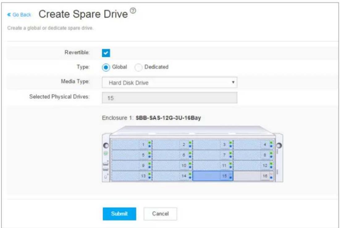
Creating Spare Drive
Spare drives can be created at anytime, as long as there are unassigned drives available. The spare drive should be the same type (SSD or HDD) as the drives in the pool. Note that in this example, there is only one pool created, so the Type is irrelevant.
To create a spare drive, go to the Pool menu, and click Create a Spare Drive. Click to select an available hard disk, the selected disk become darker in color to indicate selection. Change the following spare drive options as desired:
• Revertible (reverts back to spare drive status after RAID is repaired or restored)
• Type (Global - available for any pool on the system, or Dedicated - assigned to specific pool)
• Media (HDD or SSD, must be same as pool)
Click on the Submit button to create the spare drive.
Create spare drive
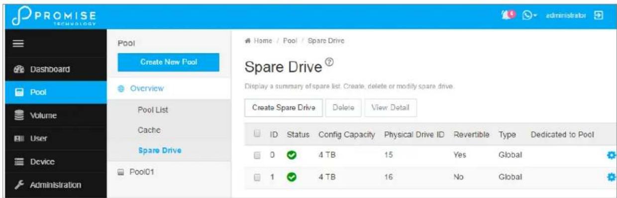
Spare Drive List
Spare drives are listed in the Spare Drive list. Use this menu to delete a spare drive or to view more details about a spare drive. Click the gear icon and select Detail to view information about a spare drive.
To delete a spare drive, select it in the list and click on the Delete button. You will need to confirm that you want to delete the spare drive in a pop-up menu. Type "confirm" and click the Confirm button to remove the spare drive. The drive status reverts to an unassigned available drive.
View spare drives
Creating an SSD Cache
You have the option to use installed SSD drives for the read and/or write data cache. To create an SSD write cache, there must be two SSD drives installed in order to mirror the drives. For a read cache, at least one SSD is needed (no mirroring for the read cache). SSD caching greatly improves read and/or write performance of the system.
To create an SSD cache, go to the Pool menu, expand the Overview, and click on Cache. This menu lists any previously created read or write SSD caches. Click the Create Cache button.
Create SSD Cache
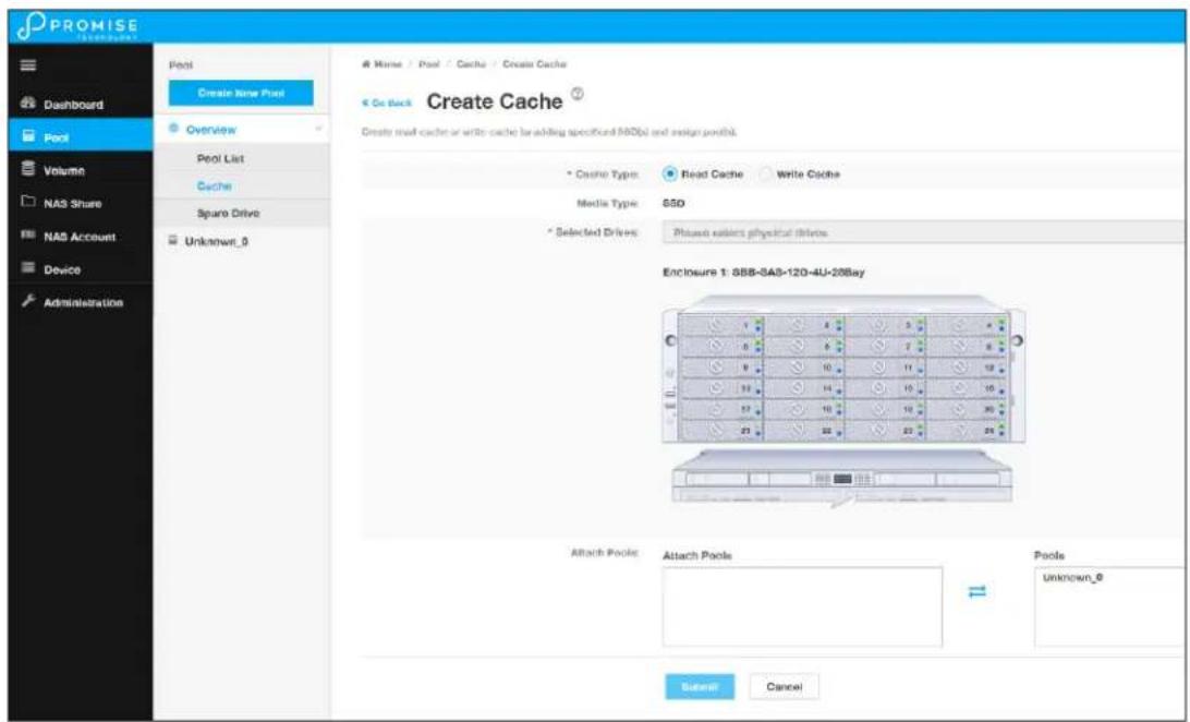
Use the Create Cache menu to select SSD drives and create a read or write cache.
CREATING A VOLUME
Now that we have a storage pool, we can create volumes in the pool. The main decision for volumes is whether to use thin or full provisioning. Thin provisioning allows for creation of volumes which have a total cumulative capacity that is greater than the physical capacity available for the pool. Thin provisioning might not be appropriate for certain applications. So plan your storage utilization carefully.
To create a new volume, go to the Volume menu, click the Create New Volume button, and Create Volume menu appears.
Create new volume
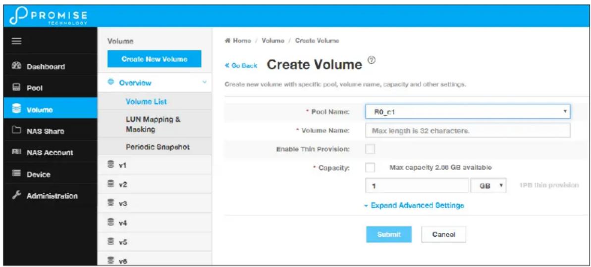
In the Create Volume menu, enter a name for the new volume, and click the Enable Thin Provisioning option if you plan to use thin provisioning on this pool.
Next, enter a value for the volume capacity, note that you need to specify TB or GB in a separate pull-down menu. Click on the Submit button to create the new volume. This volume should now appear listed in the Volume List. Volumes are exported by default. An exported volume becomes available for sharing on the storage network. To Un-export a volume, use the Volume list menu.
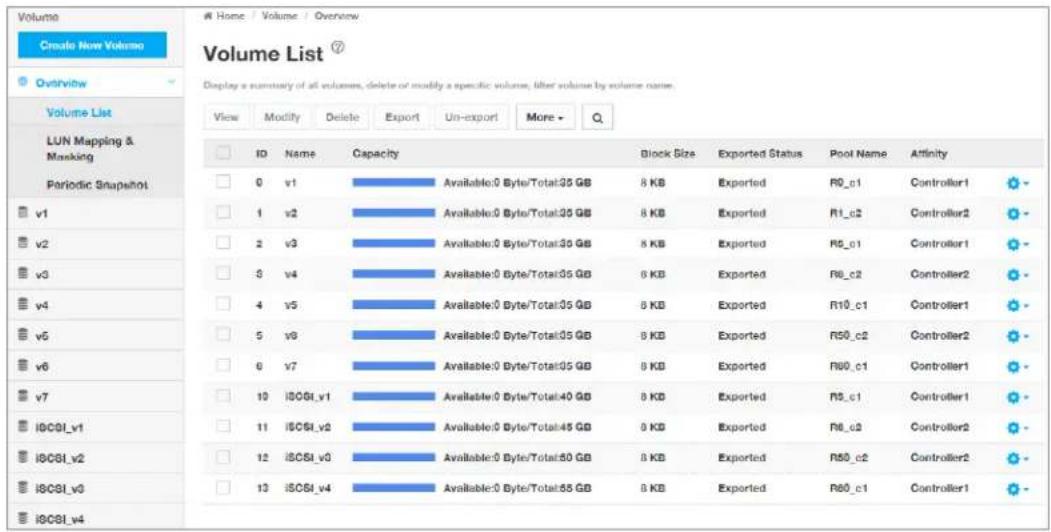
Volume List
Use the Volume List menu to Un-export, Export, or Delete existing volumes. Also, this is where you can link to LUN Mapping and Masking to enable it.
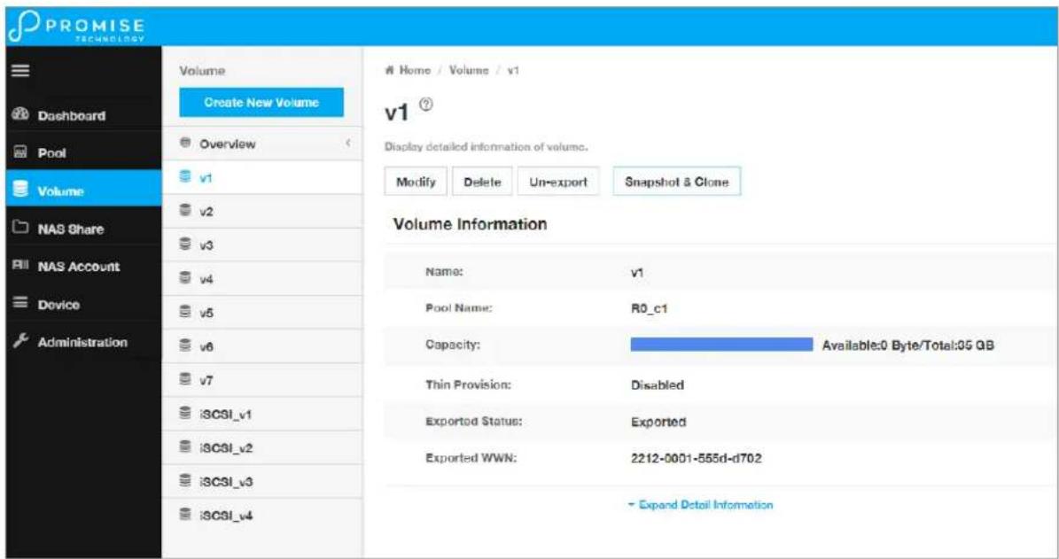
To view more detailed information for a volume, you can either click the gear icon for the volume and select the Detail option, or click on the volume name in the left panel under Overview. Use the individual volume menu to link to the Snapshot and Clone menus.
Volume List
Individual volume information
Snapshots
A volume snapshot is used to capture a read-only copy of the volume status at the time the snapshot is created. The snapshot is saved in case it is necessary to revert back to the volume status at the time of the snapshot for disaster recovery. This is called a rollback.
Rolling back to a previous snapshot will discard all data changes that have occurred between the time of the snapshot and the current time.
Snapshots and clones are a quick and low cost (in terms of capacity used) means of backing up a volume for the purpose of recovery.
To create a volume snapshot, click on the volume name in the left panel, click the Snapshot & Clone button, you will see the Snapshot & Clone list, then click the Create Snapshot button.
Create Snapshot
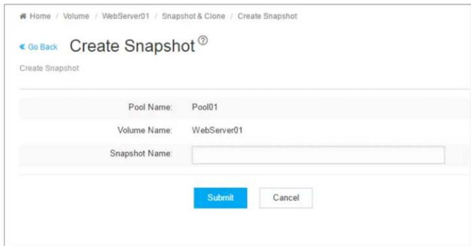
In the Create Snapshot menu, enter a name for the snapshot and click the Submit button. The snapshot will appear listed Snapshot and Clone list.
Clones
A clone is created from a snapshot as a means of backing up the snapshot. If you intend to delete a snapshot that has a clone, you must first delete the clone.
To create a snapshot clone, first create the snapshot, select it in the Snapshot & Clone list, click on the Create Clone button.
Create Clone
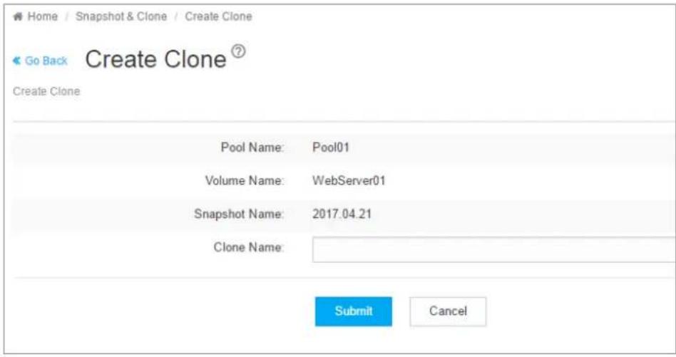
In the Create Clone menu, enter a name for the clone and click the Submit button.
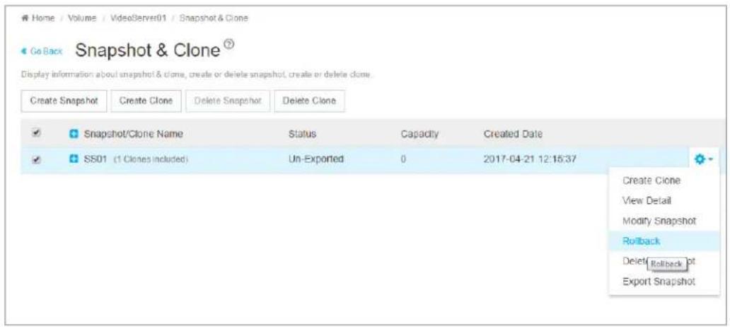
Rollbacks
To rollback using a snapshot, select the snapshot, click on the gear icon, and choose the Rollback option. You are required to confirm that you want to rollback using the snapshot in a pop-up menu. Type "confirm" and click on the Confirm button to proceed with the rollback. Remember, any changes in the volume that have occurred since the snapshot will be lost.
Rollback option
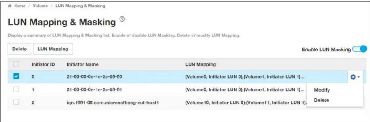
LUN Mapping and Masking
This feature applies to Fibre Channel SAN and iSCSI subsystems and controls user access to storage resources.
- LUN Mapping – Maps a LUN to an initiator; a LUN can be mapped to multiple initiators.
- LUN Masking – The process of applying a LUN Map.
To access LUN mapping:
- Click the Volume tab.
- Under Overview, click the LUN Mapping & Masking menu link.
To enable or disable LUN Masking, click on the Enable LUN Masking slider to toggle on LUN masking.
Adding a LUN Map
For Fibre Channel and iSCSI (SAN) systems, you can set up an Initiator LUN map.
A maximum of 256 logical drives can be mapped to a Fibre Channel initiator.
To assign a LUN to an initiator, the initiator must have been previously added to the initiator list.
(See "Adding a Fibre Channel or iSCSI Initiator" on page 93.)
To add a LUN map:
- Click the Volume tab.
- Click on LUN Mapping & Masking.
- Click the LUN Mapping button. (See sample menu on next page)
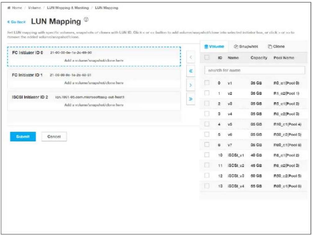
-
In the LUN Mapping menu, the Initiators appear on the left side with volumes (including snapshots and clones) on the right. Use this menu to select a volume or volumes to assign to an initiator. Click the box to select an ID number of existing volumes, snapshots or clones in the right side, and use the arrow transfer button to assign them to the preferred initiator.
-
Click the Submit button.
The new LUN map is created.
- By default, LUN Mapping & Masking is not enabled. To use LUN Mapping & Masking, it must be enabled in the LUN Mapping & Masking tab.
LUN Mapping
Editing a LUN Map
Editing a LUN map is the action of assigning a logical drive or LUN to an initiator. By changing the assignment, you change the initiator's access.
To edit a LUN map:
- Click the Volume tab.
- Click on LUN Mapping & Masking.
- Select the LUN to be edited.
- Click on the Gear icon and select the Modify option.
-
To remove a volume from an initiator, click to select a Volume on the left side, and use the arrow transfer button to remove the volume from the initiator. To add a volume, Click the box to select an ID number of existing volumes in the right side, and use the arrow transfer button to assign the volume to the preferred initiator.
-
Click the Submit button.
The modified LUN map is created.
LUN Mapping & Masking
Deleting a LUN Map
Deleting a LUN map prevents the initiator from accessing the LUN while LUN masking is enabled.
To delete a LUN map:
- Click the Volume tab.
- Click on LUN Mapping & Masking.
The list of LUN maps appears.
- Click to select the LUN map you want, then click the Gear icon, and select the Delete option
- In the Confirmation box, type the word "confirm" in the field provided and click the Confirm button.
Enabling and Disabling LUN Masking
Disabling LUN masking allows all initiators to access all LUNs in your data storage. However, disabling LUN masking does not delete existing LUN maps.
These actions require Administrator or Super User privileges.
To enable or disable LUN masking:
- Click the Volume tab.
-
Click on LUN Mapping & Masking.
-
Click on the Enable LUN Masking slider to toggle off (disable) or on (enable) LUN masking.
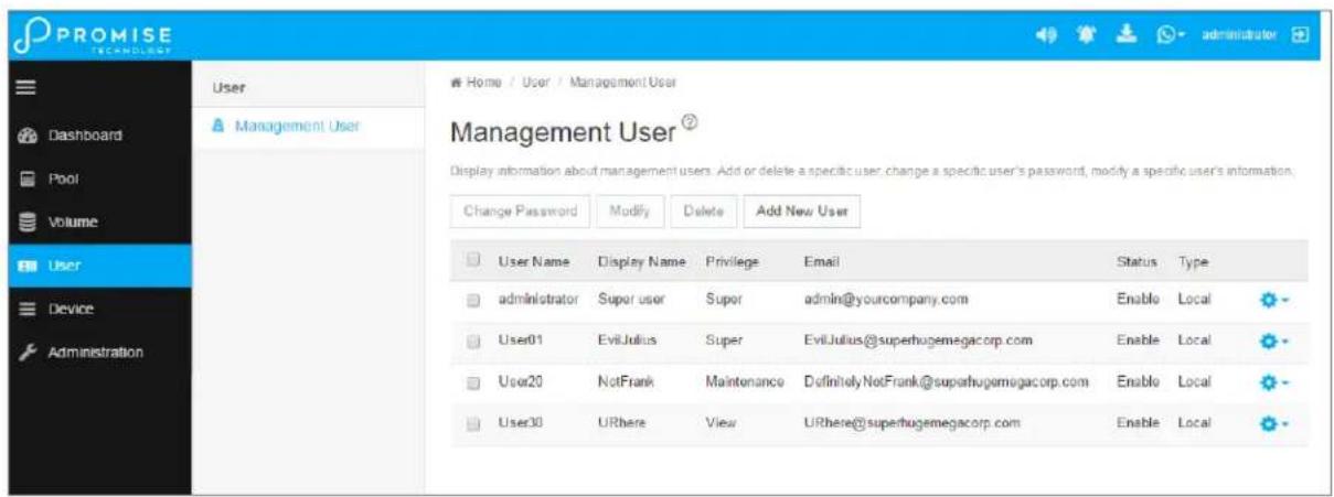
MANAGEMENT USER
Management users can view the VTrak D5000 user interface or make configuration changes according to the privilege level configured for the user. Only Super user level management users can add, remove or modify users. Note that the Administrator has Super user level privilege.
Management User list
Making Maintenance Mode Settings
Each controller has its own IP addresses for access when the controller goes into maintenance mode.
To make maintenance mode settings:
- Click the Device tab.
- Click the Network Management tab.
- Click the Management Portal tab.
- For maintenance mode, use the Static IP settings.

Important
Static IP settings are used when the controller is in maintenance mode.
Management Portal
Management Portal ⑦
Display a summary of Floating IPs and Static IPs. View detail information, change configuration for a specific floating IP or a specific static IP.
| View | Modify | Enable | Disable |
Floating IP
| Controller ID | Port ID | Protocol Family | IP Address | IP Mask | Link Status | |
| 1 | 1 | IPv4 (Enabled) | 102.168.201.182 | 255.255.255.0 | Up | |
| 1 | 1 | IPv6 (Disabled) | 2001:1 | 111:1 | Up |
Static IP
| Controller ID | Port ID | Protocol Family | IP Address | IP Mask | |
| 1 | 1 | IPv4 (Enabled) | 10.0.0.3 | 255.0.0.0 | |
| 1 | 1 | IPv6 (Disabled) | 2001::9 | ffff:: | |
| 2 | 1 | IPv4 (Enabled) | 10.0.0.5 | 255.255.255.0 | |
| 2 | 1 | IPv6 (Disabled) | fd00::5 | ff00:: |
Adding a New User
This action requires Administrator or Super User privileges.
To create a user:
- Click the Administration tab.
- Click the Management User tab
- In the Management User menu, click the Add New User button.
-
In the Add User dialog box, enter the information in the fields provided:
-
Name – This is the user's login name
- Display Name
- Password
- Retype Password
-
User Email – Required for event notification
-
Choose a privilege level from the drop-down menu. See the table below for a description of the privilege types.
- (Optional) Uncheck to disable this User account.
- Click the Submit button. The user is added to the list.
| User Privileges | |
| Level Meaning | |
| View | Allows the user to See all status and settings but not to make any changes |
| Maintenance | Allows the user to perform maintenance tasks including Media Patrol, and Redundancy Check |
| Power | Allows the user to create (but not delete) pools and volumes, change RAID levels, change stripe size; change settings of components such as pools, volumes, physical drives, and the controller |
| Super | Allows the user full access to all functions including create and delete users and changing the settings of other users, and delete pools and volumes. The default “administrator” account is a Super User |
Changing User Settings
This action requires Administrator or a Super User privileges.
To change user settings:
- Click the Administration tab.
- Click the Management User tab
- In the Management User menu, choose the user and click the Modify button.
-
Make settings changes as required:
-
For the Status box, check to enable this user account, uncheck to disable this user account
• In the User Settings dialog box, enter a new Display Name or User Email address -
Choose a new Privilege level from the drop-down menu.
-
Click the Save button.
Changing User Passwords
This action requires Administrator or Super User privileges.
To change a user's password:
- Click the Administration tab.
- Click the Management User tab
- In the Management User menu, choose the user and click the Change Password button.
-
In the Change Password dialog box, enter the information in the fields provided:
-
New Password
-
Retype Password
-
Click the Save button.
Deleting a User
This action requires Administrator or Super User privileges
To delete a user:
- Click the User tab.
-
In the Management User menu, choose the user and click the Delete button.
-
In the Confirmation box, type the word "confirm" in the field provided and click the Confirm button.

Note
The Administrator account cannot be deleted and the privilege level cannot be changed.
Setting User Event Subscriptions
By default, event notification is set to the Major (severity) level for all events.
Subscribing users receive notification of events at the chosen severity level and all higher levels.

Note
Each user must have a valid Email address to receive events. Also, the email service must be properly configured with the SMTP server, including login information if necessary.
Changing a user subscription requires Administrator or Super User privileges.
To set a user event subscription:
- Click the User tab.
- In the User list, click the Gear icon for the user to configure, and choose the Event Subscription option.
- Make settings changes as required:
- For the Enable Event Notification box, check to enable for this user, uncheck to disable.
-
Click to change the priority options for each category of event.
-
Click the Submit button.
DEVICE
Use the Device menus to monitor subsystem status and make settings changes to subsystem components, drives, network settings, etc.
Device Overview
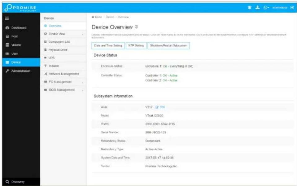
Viewing Subsystem Information
To view subsystem information, click the Device menu tab.
The list of subsystems and host controllers is displayed in Device Overview. Subsystem information includes:
- Alias, if assigned
- Model
- WWN – World Wide Name
- Serial number
- Redundancy status
- Redundancy Type
- System date and time
- Time Zone
- Vendor
Restarting the Subsystem
This function shuts down the subsystem and then restarts it.
To restart the subsystem:
- Click the Device tab.
- Click the Overview icon.
- Click the Shutdown/Restart Subsystem button.
- Choose the Apply to option, Subsystem, Controller 1 or Controller 2.
- Click the Restart button.
- Type the word "confirm" in the field provided.
- Click the Confirm button.
When the controller shuts down, your WebPAM PROe connection is lost.
- Wait at least two minutes.
- In your browser, click Logout in the WebPAM PROe Header, then log in again.
If you cannot log in immediately, wait 30 seconds and try again.
Shutting Down the Subsystem
This function shuts down the RAID subsystem without restarting it.
To shutdown the subsystem:
- Click the Device tab.
- Click the Overview icon.
- Click the Shutdown/Restart Subsystem button.
- Choose the Apply to option, Subsystem, Controller 1 or Controller 2.
- Click the Shutdown button.
- Type the word "confirm" in the field provided.
- Click the Confirm button.
When the controller shuts down, your WebPAM PROe connection is lost.

Important
If your RAID subsystem manages JBOD expansion units, you must follow the proper startup procedure.
Restarting the Subsystem after a Shutdown
To start the RAID subsystem:
- Press the Power button on the front left side of the device being restarted.
- Wait at least two minutes.
- Open your browser and log into WebPAM PROe.
If you cannot log in immediately, wait 30 seconds and try again.
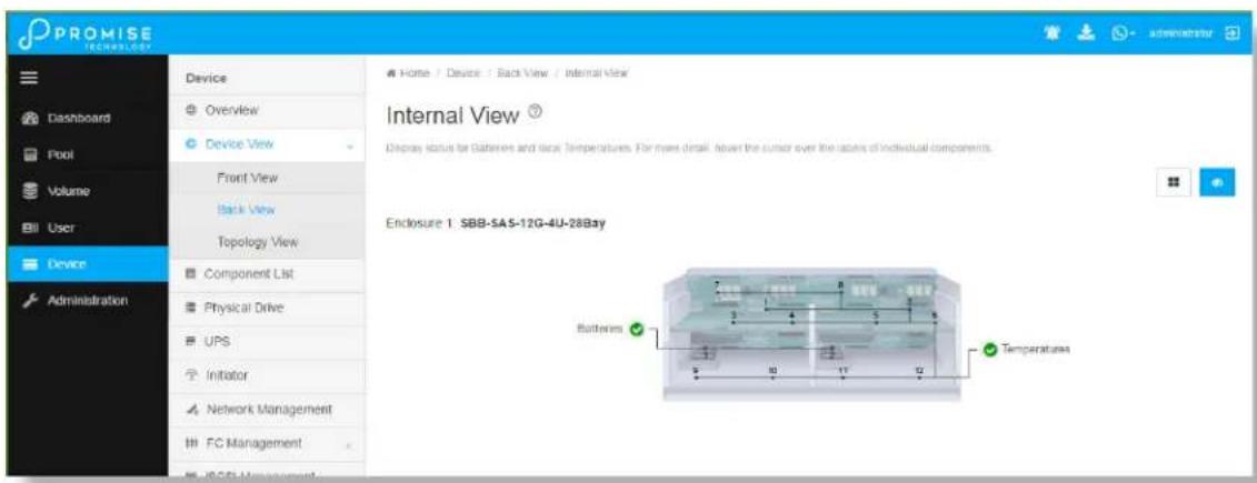
Device View
The Device View menus display a real time virtual representation of the device used to check status of the subsystem and its components. Choose the Front View, Back View, and Internal View (click button in Back View menu).
Hover the cursor over different components to see a summary of the status for that component.
Device Front View
Device Back View
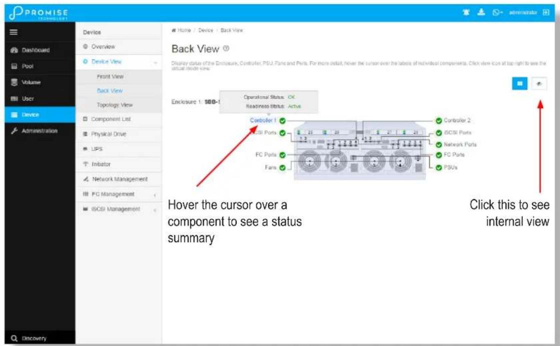
Device Internal View
Viewing Enclosure Information
To view enclosure information:
- Click the Device tab.
-
Click the Component List icon.
-
Click the Enclosure and select View in the gear icon.
Enclosure information includes:
- Enclosure ID
- Enclosure Type
• Operational Status of PSUs - Operational Status of Fans, including Current Fan Speed and Healthy Threshold
• Temperature Sensors for Controllers, PSUs and Backplane include Location, Status and current Temperature, and Healthy Threshold
• Voltage Sensors for Controllers and PSUs, including Sensor Type, Current Voltage, and Healthy Threshold
Locating an Enclosure
To locate an enclosure:
- Click the Device tab.
- Click the Component List icon.
- Click the Enclosure you want, then click the Locate button.
The enclosure LEDs blink for one minute.
Making Controller Settings
In a dual-controller RAID subsystem, settings made to one controller are applied to both controllers.
To make controller settings:
- Click the Device tab.
- Click the Component List icon.
- For the controller you want to configure, then click the Gear icon and select the Settings option.
-
Make settings changes as required:
-
Enter, change or delete the alias in the Alias field.
- HDD Power Saving – Choose time periods from the drop-down menus.
After an HDD has been idle for the set period of time:
* Power Saving Idle Time – Parks the read/write heads.
* Power Saving Standby Time – Lowers disk rotation speed.
* Power Saving Stopped Time – Spins down the disk (stops rotation).
- Coercion – Check the box to enable or uncheck to disable.
- Coercion Method – Choose a method from the drop-down menu:
* GBTruncate
* 10GBTruncate
* GrpRounding
* TableRounding
- Write Back Cache Flush Interval – Enter a value into the field, 1 to 12 seconds.
- Enclosure Polling Interval – Enter a value into the field, 15 to 255 seconds.
- Adaptive Writeback Cache – Check the box to enable or uncheck to disable.
- Host Cache Flushing – Check the box to enable or uncheck to disable.
- Forced Read Ahead (cache) – Check the box to enable or uncheck to disable.
- SMART Log – Check the box to enable or uncheck to disable.
- SSD Trim Support – Check the box to enable or uncheck to disable.
• SMART Polling Interval – Enter a value into the field, 1 to 1440 minutes - Pseudo Device Type - From the drop-down menu, choose:
* DAS
* CTRL
- Click the Save button.
Viewing Controller Information
To view controller information:
- Click the Device tab.
- Click the Component List icon.
- Click the controller you want, then click the View button.
Basic controller information includes:
- Controller ID
- Alias – If assigned
- Readiness Status
- Power On Time
• LUN Mapping method - Serial Number
- WWN – World Wide Name
- Dirty Cache Usage – Percentage
- Boot Loader Version
- Firmware Version
-
Software Version
-
Operational Status
• SCSI Protocol Supported - Part Number
- Hardware Revision
- Cache Usage – Percentage
- Host Cache Flushing
- Boot Loader Build Date
- Firmware Build Date
- Software Build Date
Advanced controller information includes:
| Slot 1 Memory Type | Slot 1 Memory Size |
| Slot 2 Memory Type | Slot 2 Memory Size |
| Slot 3 Memory Type | Slot 3 Memory Size |
| Slot 4 Memory Type | Slot 4 Memory Size |
| M.2 Device Present 1 | M.2 Device Size 1 |
| M.2 Device Present 2 | M.2 Device Size 2 |
| LUN Affinity | ALUA * |
| Controller Role | Flash Type |
| Flash Size | NVRAM Type |
| NVRAM Size | Preferred Cache Line Size |
| Coercion * | Coercion Method * |
| SMART Log | SMART Polling Interval * |
| Write Back Cache Flush Interval * | Enclosure Polling Interval * |
| Adaptive Writeback Cache * | Forced Read Ahead |
| Forced Read Ahead (cache) * | Power Saving Standby Time |
| Power Saving Idle Time * | Cache Line Size |
| Power Saving Stopped Time | Pseudo Device Type |
| SSD Trim Support: |
Items with an asterisk (*) are adjustable under Controller Settings.
Buzzer Settings
To make buzzer settings:
- Click the Device tab.
-
Click the Component List icon.
-
Choose the Enable Buzzer / Disable Buzzer option to enable or disable the buzzer.
-
Choose the Turn on Buzzer / Turn off Buzzer option to turn the buzzer on or off. Note that while the buzzer is on, the status reads Sounding; when the buzzer is off, the status reads Silent.

Caution
If you disable the buzzer, it is disabled for all events. To stop the buzzer from sounding, you can use either the Mute Alarm button located on the front of the subsystem hardware, or follow the instructions below.
Silencing the Buzzer
To silence the buzzer, you can press the Mute Alarm button on the front of the VTrak enclosure hardware, located on the left side under the power button and USB ports. Or, click on the virtual Mute Buzzer button at the top of the user interface in WebPAM PROe. This only appears when the buzzer is sounding.
Managing Physical Drives
Viewing Physical Drive Information
To view physical drive information:
- Click the Device tab.
- Click the Physical Drive icon. Information for each drive is listed in the menu.
Physical drive information includes:
- Physical Drive ID – ID number of the physical drive
- Operational Status – OK is normal, Stale, PFA, Dead
- Model Number– Make and model of the drive
- Drive Interface Type – SATA or SAS
- Location – Enclosure number and slot number
- Configuration Status – Pool number or spare number
• Physical Capacity – Total capacity in TB
Making Global Physical Drive Settings
To make global physical drive settings:
- Click the Device tab.
- Click the Physical Drive icon.
- Click the Global Physical Drive Settings button.
- Check the boxes to enable, uncheck to disable.
For SATA drives:
- Enable Write Cache
- Enable Read Look Ahead Cache
• DMA Mode (use pull down menu to select option)
• Medium Error Threshold (Default is 64, range is 0-4294967294)
For SAS drives:
- Enable Write Cache
- Enable Read Look Ahead Cache
-
Enable Read Cache
• Medium Error Threshold -
Click the Save button.
Managing UPS Units
Viewing UPS Information
To view information about a specific UPS unit:
- Click the Device tab.
- Click the UPS icon.
UPS information includes:
- UPS ID
- Status
- Model
- Battery Capacity – Backup capacity expressed as a percentage.
- Run Time Remaining
Making UPS Settings
These settings control how the VTrak D5000 subsystem detects the UPS unit and responds to data reported by the UPS unit.
To make UPS settings:
- Click the Device tab.
- Click the UPS icon.
- Click the UPS Settings button.
- Perform the following actions as required:
- Choose a Detection Setting from the drop-down menu:
* Auto – Default. If a UPS is detected when the subsystem boots, the setting changes to Enable.
* Enable – Monitors UPS. Reports warnings and logs events.
* Disable – Does not monitor UPS.
- Type values into the Threshold fields:
* Running Time Remaining Threshold – Actual time below this value resets adaptive writeback cache to writethrough. Default is 5 minutes, range is 3-20 minutes.
- For UPS units with network cards, type the IP addresses or DNS names in fields UPS 1 and UPS 2. See Note 2.
- Press Submit to save your settings.
Note 1: VTrak D5000 supports multiple UPS units using network or USB connections, but not a combination of both methods.
Note 2: To specify UPS units by DNS names, ask your IT administrator to add the DNS names to the DNS server, before you make UPS settings. DNS settings must first be configured in Network Management using the Global Settings menu.
MANAGING INITIATORS
Adding a Fibre Channel or iSCSI Initiator
You must add an initiator to the VTrak D5000's initiator list in order to map your LUN or logical drive to the initiator.
This action requires Administrator or Super User privileges.
To add a Fibre Channel or iSCSI initiator to the list:
- Click the Device tab.
- Click the Initiator icon.
- Click the Add Initiator button.
- Choose the network Type (FC or iSCSI)
- Input the initiator name in the fields provided.
A Fibre Channel initiator name is the World Wide Port Name of the initiator, composed of a series of eight, two-digit hexadecimal numbers. The iSCSI initiator name is composed of a single text string. - Click the Submit button.
The initiator is added.
Viewing Initiators
The VTrak D5000's initiator list displays initiators available for mapping to a LUN or logical drive. You must add initiators to the VTrak D5000's initiator list to make them available for mapping to a LUN.
To view a list of initiators:
- Click the Device tab.
- Click the Initiator icon.
The list of initiators appears. Initiator information includes:
• ID – Initiator 0, Initiator 1, Initiator 2, etc.
• Type - Choose FC or iSCSI
Fibre Channel – WWPN: Enter the World Wide Port Name of the initiator, composed of a series of eight, two-digit hexadecimal numbers.
iSCSI – Name: Enter the iSCSI name of the initiator device, composed of a single text string.
Deleting an Initiator

Caution
If you delete an initiator, you delete the LUN map associated with that initiator. Verify that the LUN map is no longer needed before deleting the initiator
This action requires Administrator or Super User privileges.
To delete a Fibre Channel initiator:
- Click the Device tab.
- Click the Initiator icon.
- Click the trash can icon on the initiator if you want to delete it.
- In the Confirmation box, type the word "confirm" in the field provided and click the Confirm button The initiator is removed from VTrak D5000's initiator list.
Managing Network Connections
Making Virtual Management Port Settings
The VTrak D5000 subsystem has a virtual management port, enabling you to log into a VTrak D5000 with dual controllers using one IP address.
You initially made these settings during subsystem setup. You can change them later as required.

Caution
Changing virtual management port settings can interrupt your WebPAM PROe connection and require you to log in again.
To make virtual management port settings:
- Click the Device tab.
- Click the Network Management tab.
- Under Floating IP, click on the gear icon and choose the Modify option.
- In the new menu, make the following settings are needed:
- Check the Enable DHCP box to enable a DHCP server to make your network settings. DHCP is currently supported in IPv4 only. Note that you will have the option to enable Auto DNS.
- For manual network settings, type the RAID subsystem's IP address, subnet mask and gateway IP address into the fields provided.
- Click the Save button.
Making Maintenance Mode Port Settings
The IP settings of management ports are also configured in Network Management.
To make physical management port settings:
- Click the Device tab.
-
Click the Management Portal icon.
-
Under Static IP, click on the gear icon and choose the Modify option.
-
In the new menu, make the following settings are needed:
-
Check the Enable DHCP box to enable a DHCP server to make your network settings. DHCP is currently supported in IPv4 only. Note that you will have the option to enable Auto DNS.
- For manual network settings, type the RAID subsystem's IP address, subnet mask and gateway IP address into the fields provided.
-
You can choose to Enable Physical IP.
-
Click the Save button.
Managing Fibre Channel Connections
Viewing Fibre Channel Node Information
To view Fibre Channel node information:
- Click the Device tab.
- Click the FC Management tab.
- Click the Node tab.
Node information includes:
• Worldwide Node Name (WWNN)
• Maximum Frame Size
• Supported Fibre Channel Class
- Supported Speed
Viewing Fibre Channel Port Information
To view Fibre Channel port information:
- Click the Device tab.
- Click the FC Management tab.
-
Click the Port tab.
-
Click the gear icon in the list of FC ports and select the View option.
Port information includes:
- Controller ID
- Link Status
- Topology
- Alias WWNN - World Wide Node Name
- Fabric WWPN
- Current Speed
- Configured Link Speed
-
Hard ALPA
-
Port ID:
- Identifier - (hexadecimal)
• WWPN - Worldwide Port Name
• Number Of Current Aliases - Fabric WWNN
- Link Type
- Configured Topology
Making Fibre Channel Port Settings
To make Fibre Channel port settings:
- Click the Device tab.
- Click the FC Management tab.
-
Click the Port tab.
-
Click the gear icon in the list of FC ports and select the Modify option.
-
Make these changes as required:
-
Choose a configured link speed from the drop-down menu. The choices are Auto (default), 4 Gb/s, 8 Gb/s and 16 Gb/s.
- Choose a topology from the drop-down menu.
-
Enter a Hard ALPA in the field provided. Enter 255 to disable Hard ALPA.
-
Click the Save button.
Port Setting Information
The examples below show the type of attached topology you achieve based on your connection type and the configured topology you select.
Example 1: If you connect the VTrak D5000 to a Fibre Channel switch and choose NL-Port topology, you create a Public Loop attached topology.
Example 2: If you have a Point-to-Point attached topology, you made a direct connection (no Fibre Channel switch) and selected N-port topology.

Note
In some cases, HBA settings to N-Port only work if connected to the switch. Refer to your HBA manual for more information.
Viewing Fibre Channel Port Statistics
To view Fibre Channel port statistics:
- Click the Device tab.
- Click the FC Management tab.
- Click the Statistics tab.
- Click the gear icon in the list of FC ports and select the View option.
Viewing Fibre Channel Logged-in Devices
Logged-in devices refers to all Fibre Channel devices currently logged into the VTrak D5000. The device list includes:
- Fibre Channel ports
- Fibre Channel switches, if attached
- Fibre Channel initiators
To view a list Fibre Channel logged-in devices:
- Click the Device tab.
- Click the Fibre Channel Management icon.
- Click the Logged In Device tab.
To add a Fibre Channel initiator in the list, select it and click on the Add to Initiator List button. This is the method described in "Adding a Fibre Channel or iSCSI Initiator" on page 93.
Viewing Fibre Channel Initiators on the Fabric
To view a list Fibre Channel initiators on the fabric:
- Click the Device tab.
- Click the FC Management tab.
- Click the Device on Fabric tab.
Also see "Viewing Initiators" on page 94.
To add a Fibre Channel initiator in the list, select it and click on the Add to Initiator List button. See “Adding a Fibre Channel or iSCSI Initiator” on page 93.
Viewing Fibre Channel SFPs
The term SFP refers to Small Form Pluggable transceivers used in Fibre Channel ports. The SFPs convert electrical signals to optical signals and send them over the Fibre Channel fabric, where another transceiver converts the optical signal back to an electrical signal again.
To view a list Fibre Channel SFPs:
- Click the Device tab.
- Click the Fibre Channel Management icon.
- Click the SFP tab.
SFP information includes:
- Controller ID
- FC Port ID
- Connector type
- Transceiver type
- Transceiver code
- Vendor name
MANAGING ISCSI CONNECTIONS
Viewing iSCSI Target Information
To view information about the iSCSI target:
- Click the Device tab.
- Click the iSCSI Management icon.
- Click the Target tab. (Note that you need to click Expand Detail Information to view the entire list)
Target information includes:
• ID – ID number of the target.
- Status – Up or down.
- Name – iSCSI qualified name (iqn) of this target.
- Alias – Maximum of 32 characters. Use letters, numbers, space between words, and underscore. An alias is optional.*
- Error Recovery Level – Error recovery level supported.
- Initial R2T – Allows initiator to begin sending data to a target without receiving a ready to transfer command.
- Max Outstanding R2T – Maximum number of R2T PDUs the target can have outstanding for a single iSCSI command.
- Max Burst Length – Maximum length of a solicited data sequence in bytes.
- Data Digest – Adds a data digest (CRC).*
- Header Digest – Enables the use of header digest (CRC).*
- Data PDU in Order – Enables placement of data in PDU order
- Data Sequence in Order – Enables placement of data in sequence order
- Default Time to Wait – After a dropped connection, the number of seconds to wait before attempting to reconnect
- Default Time to Retain – Number of seconds after time to wait (above) before reassigning outstanding commands
- Uni-directional CHAP Authentication – Uni-directional (peer) CHAP authentication, enabled or disabled*
- Bi-directional CHAP Authentication – Bi-directional (local) CHAP authentication, enabled or disabled*
• Maximum Connections – The maximum number of concurrent connections
- Immediate Data – Enables the initiator to send unsolicited data with the iSCSI command PDU.
- First Burst Length – In bytes.
- Assigned Portal IDs
- Keep Alive - Enable or Disable
Making iSCSI Target Settings
To make target settings:
- Click the Device tab.
-
Click the iSCSI Management icon.
-
Click the Target tab.
-
Click the target you want, then click the Modify button.
-
Make settings changes are required:
-
Alias
- Enable/Disable Keep Alive
- Enable/Disable Header Digest
- Enable Data Digest
- Enable Bi-directional CHAP Authentication
-
Enable Uni-directional CHAP Authentication
-
Click the Save button.
Viewing a List of iSCSI Sessions
To view a list of iSCSI sessions:
- Click the Device tab.
- Click the iSCSI Management icon.
- Click the Session tab.
iSCSI session information includes:
• ID – ID number of the session
- Controller ID - Controller 1 or 2
• Target Alias – Alias of the target
- Initiator Alias – Part of the IQN
- Portal ID – ID number of the portal
- Portal IP - IP address of the portal
- Status – Active or inactive.
Viewing iSCSI Session Information
To view a list of iSCSI sessions:
- Click the Device tab.
- Click the iSCSI Management icon.
- Click the Session tab.
- Click the View button.
Deleting an iSCSI Session
To delete an iSCSI session:
- Click the Device tab.
- Click the iSCSI Management icon.
- Click the Session tab.
- Click the iSCSI session you want and click the Delete button.
- Type "confirm" in the field provided, then click the Confirm button.
Viewing iSCSI iSNS Information
To view information about iSNS:
- Click the Device tab.
- Click the iSCSI Management icon.
- Click the iSNS tab.
The information includes:
- IO Portal ID
- Type
- Controller
- Status
- Server IP
- Server Port
Making iSCSI iSNS Settings
To make iSNS settings:
- Click the Device tab.
- Click the iSCSI Management icon.
- Click the iSNS tab.
- Click on a portal to select it.
-
Click the Modify button.
-
Make settings changes are required:
-
Enable (check to enable)
• Server Port (1-65535) - Server IP
-
IO Portal ID
-
Click the Submit button.
Viewing a List of iSCSI CHAPs
To view a list of iSCSI CHAPs:
- Click the Device tab.
- Click the iSCSI Management icon.
- Click the CHAP tab.
CHAP information includes:
• ID – ID number of the CHAP
- Type – Peer or local
Peer is one-way or uni-directional.
Local is two-way or bi-directional.
- Name – User assigned name of the CHAP
Adding iSCSI CHAPs
To add an iSCSI CHAP:
- Click the Device tab.
- Click the iSCSI Management icon.
- Click the CHAP tab.
-
Click the Create CHAP button.
-
Make your choices and inputs as required:
-
Enter a name in the Name field.
- Choose a CHAP type.
Peer is one-way or uni-directional.
Local is two-way or bi-directional. - Enter a secret of 12 to 16 characters in the Secret field.
-
Enter the secret again in the Retype Secret field.
-
Click the Submit button.
The new CHAP is added to the list.
Deleting iSCSI CHAPs
To delete an iSCSI CHAP:
- Click the Device tab.
- Click the iSCSI Management icon.
- Click the CHAP tab.
- Click the CHAP you want, then click the Delete button.
- Type "CONFIRM" into the popup menu and click the Confirm button.
The CHAP is removed from the list.
Making iSCSI CHAP Settings
When you change CHAP settings, you must change the secret. You cannot change the type (peer or local).
To make iSCSI CHAP settings:
- Click the Device tab.
- Click the iSCSI Management icon.
-
Click the CHAP tab.
-
Click the CHAP you want, then click the Modify button.
-
Make settings changes are required:
-
Enter a name in the Name field.
- Enter the current secret in the Current Secret field.
- Enter a new secret of 12 to 16 characters in the Secret field.
-
Enter the new secret again in the Retype Secret field.
-
Click the Save button.
Viewing a List of Logged-in Devices
Logged-in devices refers to all iSCSI devices currently logged into the VTrak D5000. The device list includes:
To view a list of logged-in devices:
- Click the Device tab.
- Click the iSCSI Management icon.
- Click the Logged In Device tab.
USING THE EVENT VIEWER
The Event Viewer displays log of subsystem events. Events are classified as:
- Runtime Events – A list of and information of up to about 300,000 of the most recent runtime events recorded since the subsystem was started.
| Event Severity Levels | |
| Level | Description |
| Fatal | Non-recoverable error or failure has occurred. |
| Critical | Action is needed now and the implications of the condition are serious. |
| Major | Action is needed now. |
| Minor | Action is needed but the condition is not a serious at this time. |
| Warning | User can decide whether or not action is required. |
| Information | Information only, no action is required. |
Viewing Events
To display Events:
- Click the Administration tab.
- Click the Events icon.
The log of Events appears. Events are added to the top of the list. Each item includes:
- Index number – Begins with 0 at system startup.
• Device – Disk Array, Logical Drive, Physical Drive by its ID number. - Event ID – Hexadecimal code for the specific event
- Severity – see table on previous page
- Time – Date and time the event happened.
-
Description – A description of the event in plain language.
-
Press the up and down arrow keys to scroll through the log. Choose the page size and event log page you want to view.
Saving Events
This feature saves a plain text file of runtime events to your host PC or server using your browser.
To save the Events log:
- Click the Administration tab.
- Click the Events icon.
- Click the Save button.
- Follow your browser's procedure to save the event file to the desired location.
Clearing Events
To clear the Events log:
1. Click the Administration tab.
2. Click the Events icon.
3. Click the Clear button.
4. In the Confirmation box, type the word "confirm" in the field provided and click the Confirm button.
MANAGING USERS
Viewing User Information
To view user information:
- Click the Administration tab.
- Click the Management User tab.
The list of users displays. User information includes:
- User name
- Display Name
- Privilege level
- Email address
- Status
Creating a User
This action requires Administrator or Super User privileges.
To create a user:
- Click the Administration tab.
- Click the Management User tab.
-
Click the Add New User button.
-
In the Add User dialog box, enter the information in the fields provided:
-
Name – This is the user's login name
- Display Name
- Password
- Retype Password
- User Email – Required for event notification
- Enable this user - Check box to enable the user. Click to remove check to disable.
-
Privilege - Use pull down menu to select View, Maintenance, Power, or Super user level. See the table below for a description of the privilege types.
-
Click the Submit button. The user is added to the list.
| User Privileges | |
| Level Meaning | |
| View | Allows the user to See all status and settings but not to make any changes |
| Maintenance | Allows the user to perform maintenance tasks including Rebuilding, PDM, Media Patrol, and Redundancy Check |
| Power | Allows the user to create (but not delete) disk arrays and logical drives, change RAID levels, change stripe size; change settings of components such as disk arrays, logical drives, physical drives, and the controller |
| Super | Allows the user full access to all functions including create and delete users and changing the settings of other users, and delete disk arrays and logical drives.The default “administrator” account is a Super User |
Making User Settings
This action requires Administrator or a Super User privileges.
To make user settings:
- Click the Administration tab.
- Click the Management User tab.
- In the User list, click the user you want, then click the gear icon and select the Modify option.
-
Make settings changes as required:
-
For the Enable box, check to enable this user account, uncheck to disable this user account
• In the User Settings dialog box, enter a new Display Name or User Email address -
Choose a new Privilege level from the drop-down menu. See the table on the next page.
-
Click the Save button.
Changing User Passwords
This action requires Administrator or Super User privileges.
To change a user's password:
- Click the Administration tab.
- Click the User Management icon.
- In the User list, click the user you want, then click Change Password.
- In the Change Password dialog box, enter the information in the fields provided:
- New Password
-
Retype Password
-
Click the Save button.
Deleting a User
This action requires Administrator or Super User privileges
To delete a user:
- Click the Administration tab.
- Click the User Management icon.
- In the User list, click the user you want, then click the Delete button.
- In the Confirmation box, type the word "confirm" in the field provided and click the Confirm button.

Note
The Administrator account cannot be deleted.
Setting User Event Subscriptions
By default, all users have event notification:
- Enabled
- Set to the Major (severity) level for all events
Subscribing users receive notification of events at the chosen severity level and all higher levels.

Note
Each user must have a valid Email address to receive events.
Changing a user subscription requires Administrator or Super User privileges.
To set a user event subscription:
- Click the Administration tab.
- Click the Management User tab.
- In the User list, click the user you want, then click the Subscription button.
-
Make settings changes as required:
-
For the Enable Event Notification box, check to enable for this user, uncheck to disable.
-
Click to change the priority options for each category of event.
-
Click the Save button.
Viewing Services
This feature displays all software services running on the RAID subsystem.
To view the list of software services:
- Click the Administration tab.
- Click the Service icon.
The Services list displays the Status and Start Type of the services available. These services are described in the sections that follow. To view the actions available for the various services in the list, click the gear icon for the respective service.
Email Service
Email service enables the RAID subsystem to send you Email messages about events and status changes. By default, Email service is set to Automatic.
Stopping Email Service
To stop the Email service:
- Click the Administration tab.
- Click the Service icon.
- Click the gear icon for Email service and select the Stop option.
- Click the Confirm button.
To start the Email service after stopping it:
- Click the Administration tab.
- Click the Services icon.
- Click the gear icon for Email service and select the Start option.
Restarting Email Service
To restart the Email service:
- Click the Administration tab.
- Click the Service icon.
- Click the gear icon for Email service and select the Restart option.
Making Email Settings
To change Email service settings:
- Click the Administration tab.
- Click the Service icon.
- Click the gear icon for Email service and select the Settings option.
- Make settings changes as required:
- Choose a startup type,
* Automatic – (default) Starts and runs with the subsystem.
* Manual – You start the service when you need it.
- SMTP Server IP address
- SMTP Server Port
- SMTP Authentication – Choose the Yes radio button to enable authentication or the No radio button to disable authentication.
- Authentication Username – Required if SMTP authentication is enabled.
- Authentication Password – Required if SMTP authentication is enabled.
- Sender (From) Address – The sender's name shown on notification messages.
-
Email Subject – The subject line of the notification message.
-
To enable SSL for the connection to the Email server, check the Enable SSL box.
- To send a test email, one time, check the Send a Test Email box.
- Click the Save button.
- Type "CONFIRM" in the popup menu and click the Confirm button.

Note
To verify your settings, send a test message.
SLP Service
Service Location Protocol (SLP) discovers services over the Internet. SLP applies to IPv4 protocol only.
Stopping SLP Service
To stop the SLP service:
- Click the Administration tab.
- Click the Service icon.
- Click the gear icon for SLP service and select the Stop option.
- Type "CONFIRM" in the popup menu and click the Confirm button.
To start the SLP service after stopping it:
- Click the Administration tab.
- Click the Services icon.
- Click the gear icon for SLP service and choose the Start option.
Restarting SLP Service
To restart the SLP service:
- Click the Administration tab.
- Click the Service icon.
- Click the gear icon for SLP service and select the Restart option.
- Type "CONFIRM" in the popup menu and click the Confirm button.
Making SLP Settings
To change SLP service settings:
- Click the Administration tab.
- Click the Service icon.
- Click the gear icon for SLP service and select the Settings option.
-
Choose a startup type:
-
Automatic – (default) Starts and runs with the subsystem.
-
Manual – You start the service when you need it.
-
Click the Save button.
-
Type "CONFIRM" in the popup menu and click the Confirm button.
Webserver Service
Webserver service connects the WebPAM PROe interface to the RAID subsystem though your browser.
Stopping Webserver Service
To stop the Webserver service:
- Click the Administration tab.
- Click the Service icon.
- Click the gear icon for Webserver service and select the Stop option.
- Type "CONFIRM" in the popup menu and click the Confirm button.
To start the Webserver service after stopping it:
- Click the Administration tab.
- Click the Services icon.
- Click the Webserver service and click the Start button.
- Type "CONFIRM" in the popup menu and click the Confirm button.
Restarting Webserver Service
- Click the Administration tab.
- Click the Service icon.
- Click the gear icon for SLP service and select the Restart option.
- Type "CONFIRM" in the popup menu and click the Confirm button.
Making Webserver Settings
To change Webserver service settings:
- Click the Administration tab.
- Click the Service icon.
-
Click the gear icon for SLP service and select the Settings option.
-
Make settings changes as required:
-
Choose a startup type,
* Automatic – (default) Starts and runs with the subsystem.
* Manual – You start the service when you need it. -
Session Time Out – Default is 24 minutes.
-
Click the Save button.
- Type "CONFIRM" in the popup menu and click the Confirm button.
SSH Service
Secure Shell (SSH) service enables you to access the subsystem's Command Line Interface (CLI) through a network connection.
Stopping SSH Service
To stop SSH service:
- Click the Administration tab.
- Click the Service icon.
- Click the gear icon for SSH service and select the Stop option.
- Type "CONFIRM" in the popup menu and click the Confirm button.
To start SSH service after stopping it:
- Click the Administration tab.
- Click the Services icon.
- Click the gear icon for SSH service and select the Start option.
- Type "CONFIRM" in the popup menu and click the Confirm button.
Restarting SSH Service
To restart SSH service:
- Click the Administration tab.
- Click the Service icon.
- Click the gear icon for SSH service and select the Restart option.
- Type "CONFIRM" in the popup menu and click the Confirm button.
Making SSH Settings
To change SSH service settings:
- Click the Administration tab.
- Click the Service icon.
-
Click the gear icon for SSH service and select the Settings option.
-
In the SSH Settings tab, make settings changes as required:
-
Choose a startup type,
* Automatic – (default) Starts and runs with the subsystem.
* Manual – You start the service when you need it. - Port number - Default is 22.
- Max Number of Concurrent Connections – Default is 4. Maximum number is 4.
-
Session Time Out - Default is 24 minutes.
-
Click the Save button.
- Type "CONFIRM" in the popup menu and click the Confirm button.
SSH Public Key Management
To change SSH service settings:
- Click the Administration tab.
- Click the Service icon.
- Click the gear icon for SSH service and select the SSH Public Key Management option.
-
In the SSH Public Key Management menu, make settings changes as required:
-
Click the Choose File button and locate the file with the SSH Public Key
- Enter a comment
-
Enter TFTP IP and file path information
-
Click the Upload button.
MANAGING BACKGROUND ACTIVITIES
Background activities perform a variety of preventive and remedial functions on your physical drives, disk arrays, logical drives, and other components.
You can run a background activity immediately or schedule it to run at a later time. Scheduling options are described below.
Setting options for each activity are listed after the scheduling options. These settings determine how the background activity affects I/O performance.
View Current Background Activities
To view a list of current background activities:
- Click the Administration tab.
- Click the Background Activities tab.
The list of background appears.
Currently running activities show a progress bar.
View Scheduled Background Activities
To view a list of scheduled background activities:
- Click the Administration tab.
-
Click the Background Activities tab.
The list of background appears. -
Click the Scheduler button.
The list of currently scheduled background activities appears.
Add a Scheduled Background Activity
To add a new scheduled background activity:
-
Click the Administration tab.
-
Click the Background Activities tab. The list of background appears.
-
Click the Background Activity Scheduler button.
The list of currently scheduled background activities appears.
-
Click the Add Schedule button.
-
In the new menu, choose the option (radio button) for the activity you want:
-
Redundancy Check
-
Spare Check
-
Check the box to Enable This Scheduler if you want to make the schedule active. (Remove check if you want to disable.)
-
Choose a Start Time from the drop-down menus.
The menus have a 24-hour clock.
-
Choose a Recurrence Pattern option, daily, weekly, or monthly.
-
For the Daily option, enter an interval in the Every field.
- For the Weekly option, enter an interval in the Every field and choose one or more days of the week.
-
For the Monthly option, choose, Day of the Month option then choose a number from the drop-down menu. The day of the week option then choose the day of the month from the drop-down menus.
-
Choose a Start From date from the drop-down menus.
-
Choose an End On option,
-
No end date or perpetual.
• End after a specific number of activity actions. -
Until date from the drop-down menus.
-
For Redundancy Check, choose,
• Auto Fix option – Attempts to repair the problem when it finds an error. Check to enable
- Pause on Error option – The process stops when it finds a non-repairable error. Check to enable
- Select LD – Check the boxes for the logical drives to run Redundancy Check. Check at least one logical drive
- Click the Submit button.
Change a Background Activity Schedule
To change an existing scheduled background activity:
- Click the Administration tab.
- Click the Background Activities tab.
The list of background appears.
- Click the Scheduler button.
The list of currently scheduled background activities appears.
-
Click the background activity and click the Settings button.
-
Make settings changes as required:
-
Choose a Start Time from the drop-down menus.
The menus have a 24-hour clock. - Choose a Recurrence Pattern option, daily, weekly, or monthly.
For the Daily option, enter an interval in the Every field.
For the Weekly option, enter an interval in the Every field and choose one or more days of the week.
For the Monthly option, choose the Day of the Month option or the day of the week option, and choose the day from the drop-down menu. - Choose a Start From date from the drop-down menus.
- Choose an End On option,
No end date or perpetual.
End after a specific number of activity actions.
Until date from the drop-down menus. -
For Redundancy Check, choose,
Auto Fix option – Attempts to repair the problem when it finds an error. Check to enable Pause on Error option – The process stops when it finds a non-repairable error. Check to enable
Select LD – Check the boxes for the logical drives to run Redundancy Check. Check at least one logical drive -
Click the Save button.
Enable/Disable Scheduled Background Activity
Background activity schedules are enabled by default when you create the schedule. If you want to stop a background activity now but plan to use it again in the future, disable the scheduled activity rather than deleting it.
To enable or disable change an existing scheduled background activity:
- Click the Administration tab.
- Click the Background Activities tab.
The list of background appears. - Click the Scheduler button.
The list of currently scheduled background activities appears. - Click the background activity and click the Settings button.
- Uncheck the Enable This Schedule box to disable this schedule.
Check the box to enable this schedule. - Click the Save button.
Delete a Scheduled Background Activity
To change an existing scheduled background activity:
- Click the Administration tab.
- Click the Background Activities tab.
The list of background appears. - Click the Scheduler button.
The list of currently scheduled background activities appears. - Click the background activity and click the Delete button.
- In the confirmation box, click the confirm button.
Media Patrol
Media Patrol is a routine maintenance procedure that checks the magnetic media on each disk drive. Media Patrol checks are enabled by default on all disk arrays and spare drives. Media Patrol is concerned with the media itself, not the data recorded on the media. If Media Patrol encounters a critical error, it triggers a PDM if PDM is enabled on the disk array.
Starting, Stopping, Pausing and Resuming Media Patrol
To make Media Patrol settings:
- Click the Administration tab.
- Click the Background Activities tab.
The list of background appears.
- To begin Media Patrol, click the Start button. To Pause a running Media Patrol, click on the Gear icon and select Pause; click Resume to continue the Media Patrol. To Stop a running Media Patrol, click on the Gear icon, select Stop. Stopping Media Patrol requires confirmation by typing "Confirm" in the Confirmation pop up menu and clicking on the Confirm button.
Media Patrol actions menu
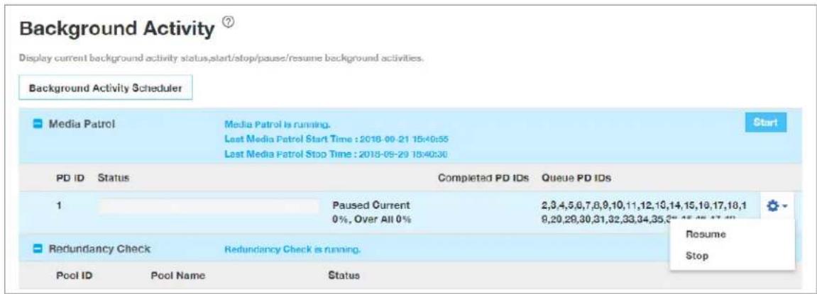
Redundancy Check
Redundancy Check is a routine maintenance procedure for fault-tolerant disk arrays (those with redundancy) that ensures all the data matches exactly. Redundancy Check can also correct inconsistencies.
Starting, Stopping, Pausing and Resuming Redundancy Check
To make Redundancy Check settings:
- Click the Administration tab.
- Click the Background Activities tab.
The list of background activities appears.
-
Use the check boxes to select the pools to run Redundancy Checks. Note that you can also enable/disable Auto Fix and Pause on Error for each pool.
-
To begin Redundancy Check on existing pools, click the Start button. To Pause a Redundancy Check for a pool, click on the Gear icon for the pool and select Pause; click Resume to continue the Redundancy Check. To Stop a running Redundancy Check, click on the Gear icon, select Stop. Stopping Redundancy Check requires confirmation by typing "Confirm" in the Confirmation pop up menu and clicking on the Confirm button.
Redundancy Check actions menu
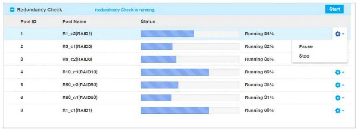
bar
Redundancy Check Redundancy Check is running. | Pool ID | Pool Name | Status | Status (%) | | :--- | :--- | :--- | :--- | | 1 | R1_c2(RAID1) | Running | 54 | | 2 | R5_c1(RAID5) | Running | 32 | | 3 | R6_c2(RAID6) | Running | 38 | | 4 | R10_c1(RAID10) | Running | 69 | | 5 | R50_c2(RAID50) | Running | 38 | | 6 | R60_c1(RAID90) | Running | 31 | | 8 | R1_c1(RAID1) | Running | 69 | StartRebuild
When you rebuild a disk array, you are actually rebuilding the data on one physical drive.
- When a physical drive in a disk array fails and a spare drive of adequate capacity is available, the disk array begins to rebuild automatically using the spare drive.
- If there is no spare drive of adequate capacity, but the Auto Rebuild function is ENABLED, the disk array begins to rebuild automatically as soon as you remove the failed physical drive and install an unconfigured physical drive in the same slot. See “Making Rebuild Settings” below.
- If there is no spare drive of adequate capacity and the Auto Rebuild function is DISABLED, you must replace the failed drive with an unconfigured physical drive, then perform a Manual Rebuild.
Starting a Rebuild
Rebuilding a disk pool is only available if the status of a pool has been determined to be degraded or critical.
- Click the Administration tab.
- Click the Background Activities icon.
The list of background activities appears. - Choose the options in the Rebuild menu, including the Source Physical Drive and Target Physical Drive from the respective pull down menus.
- Click the Submit button to begin the rebuild. A rebuild requires confirmation by typing "Confirm" in the Confirmation pop up menu and clicking on the Confirm button.
Restore Factory Default Settings
This feature restores settings to their default values.

Caution
Use this feature only when required and only on the settings that you must reset to default in order to set them correctly.
To restore all settings to their default values:
- Click the Administration tab.
- Click Restore Factory Default.
- In the Restore factory default settings screen, check the boxes beside the settings you want to reset to default value (see Factory Default Settings (by type) table below). Note that you have the option to select all firmware or all software settings to factory default, or choose each setting to reset individually for both categories.
- Click the Submit button.
- In the Confirmation box, type the word "confirm" in the field provided and click the Confirm button.

Caution
If you apply Restore Factory Default settings to the Management Network Settings, you might lose your WebPam Pro connection.
Factory Default Settings (by type)
Firmware Settings Software Settings
• Background Activities Settings
- Controller Settings
- Enclosure Settings
- FC Settings
- iSCSI Settings
• Management Network Settings
• Physical Drive Settings
- Subsystem Settings
- BGA Scheduler Settings
- Service Settings
- Web Server Settings
- SNMP Settings
- SSH Settings
- Email Settings
- NTP Settings
- User Settings
- UPS Settings
- Syslog Settings
- Time Zone Settings
- NAS Settings
Export User Database
You can save the user information and settings from one VTrak D5000 RAID subsystem, export it, and then import it to automatically configure your other VTrak D5000 RAID subsystems.
To export a user database:
- Click the Administration tab.
- Click the Import/Export tab.
- Click the Export option.
- Choose User Database radio button in the Type menu.
- Click the Submit button.

Note
The user database file is not designed to be opened or edited in the field. The User.dat file is downloaded to the default download folder.
Export Service Report
You can save a service report from a VTrak D5000 RAID subsystem.
To export a Service Report:
- Click the Administration tab.
- Click the Import/Export tab.
- Click the Export option.
- Choose Service Report radio button in the Type menu.
- Click the Submit button.
Export Configuration Script, NAS Configuration, NAS Account
You can save a system report from a VTrak D5000 RAID subsystem.
To export a user database:
- Click the Administration tab.
- Click the Import/Export tab.
- Click the Export option.
- Choose the radio button (Configuration Script, NAS Configuration or NAS Account) in the Type menu.
- Click the Submit button.
Import User Database
You can save the user information and settings from one VTrak E5000 RAID subsystem, export it, and then import it to automatically configure your other VTrak E5000 RAID subsystems.

Caution
Importing a user database overwrites the current users and user settings on your VTrak E5000 subsystem.
To import a user database:
- Click the Administration tab.
- Click the Import/Export icon.
- Click the Import option.
- Choose User Database radio button from the Type menu.
- Click the Upload button and navigate to the user database file and click the OK button.
- Click the Next button.
The system verifies that the file is a valid user database and displays any errors or warnings.
-
Click the Submit button to continue.
-
In the Confirmation box, type the word "confirm" in the field provided and click the Confirm button.
The user database is imported and applied automatically.
Import Configuration Script, NAS Configuration, NAS Account
You can save a settings script for system configuration, NAS configuration or NAS account settings and use it to automatically configure your VTrak E5000 subsystem. The script must be a plain, non-encrypted text file. From there, you can import the script from the Host PC and perform the configuration automatically.

Cautions
Do NOT attempt to write or modify a configuration script until you receive guidance from Technical Support.
Importing a settings script overwrites the current settings on your VTrak D5000 subsystem.
Or you can save the configuration from one VTrak E5000 RAID subsystem, export it, and then import it to automatically configure your other VTrak E5000 RAID subsystems. To import a configuration script:
- Click the Administration tab.
- Click the Import/Export icon.
- Click the Import option.
- Choose radio button (Configuration Script, NAS Configuration or NAS Account) in the Type menu.
- Click the Choose File button and navigate to the configuration script and click the Upload button.
- Click the Next button.
The system verifies that the file is a valid configuration script and displays any errors or warnings. - Click the Submit button to continue.
- In the Confirmation box, type the word "confirm" in the field provided and click the Confirm button.
The settings script is imported and applied automatically.
Update Firmware
Use this function to flash (update) the firmware on the VTrak D5000.
Download the latest firmware image file from PROMISE support:
http://www.promise.com/support/ and save it to your Host PC or TFTP server.

Important
Verify that no background activities are running on the RAID subsystem.
To update the firmware on the subsystem and JBOD expansion units:
- Click the Administration tab.
- Click the Firmware Update tab.
-
Choose a download option:
-
Local File through HTTP – Click the Choose File button, locate the firmware image file, click the file to choose it, then click the Open button.
-
TFTP Server – Enter the TFTP Server host name or IP address, port number and file name.
-
Optional. Check the Non-disruptive Image Update (NDIU) box.
NDIU updates the RAID controllers and I/O modules one at a time, enabling I/O operations continue during the firmware update. Updates with this option take a longer period of time to complete. Only dual controller models support this feature.
- Click the Download button.
The next screen shows the Flash Image (firmware image file) Version Number and Build Date.
- Click the Submit button.
The progress of the update displays.

Warning
Do NOT power off the subsystem during the update!
Do NOT move to any other screen until the firmware update operation is completed!
When the update is completed a message tells you to reboot the subsystem,
7. Click the OK button.
- If you chose the Disruptive Flash Method, the RAID subsystem and JBOD expansion units automatically restart.
- If you chose the Non-Disruptive Flash Method, the system automatically flashes and restarts the RAID controllers one at a time.
Automatic Restart
If you did NOT check the NDIU box, the RAID subsystem and JBOD expansion units automatically restart. That action temporarily disrupts I/O operations and drops your WebPAM PROe connection.
To reestablish your WebPAM PROe connection:
- Wait no less than two minutes.
- Click Logout in the WebPAM PROe Header, then log in again.
If you cannot log in, wait 30 seconds and try again.
- In your browser, click Logout in the WebPAM PROe Header, then log in again.
If you cannot log in immediately, wait 30 seconds and try again.
MANAGING WITH THE CLI
Making a Serial Connection
Before you begin, be sure the RJ11-to-DB9 serial data cable is connected between the Host PC and the VTrak D5000 enclosure, and that both machines are booted and running.
Serial port on the VTrak D5000 controller
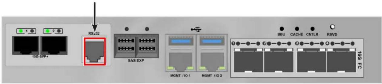
Then do the following actions:
-
Change your terminal emulation program settings to match the following specifications:
-
Bits per second: 115200
- Data bits: 8
- Parity: None
- Stop bits: 1
-
Flow control: none
-
Start your PC's terminal VT100 or ANSI emulation program.
- Press Enter once to launch the CLI.
Logging Into the CLI
- At the Login prompt, type the user name and press Enter.
The default user name is administrator.
- At the Password prompt, type the password and press Enter.
The default password is password.
The CLI screen appears.
TABLE OF SUPPORTED COMMANDS
The table below and on the following pages provides a brief description of the CLI commands available on the VTrak D5000 Series.
| Command | Action |
| about | View utility information. |
| acl | List, set, clear, cancel or refresh the ACL settings on the NAS Share |
| allowip | NFS allow share IP settings. |
| battery | View battery information or to recondition a battery. |
| bbm | View or clear the BBM defect list of the specified configured physical drive. |
| bga | View status of all current background activities.Enable or disable relevant background activities.Modify the background task rate for each of the background tasks. |
| bgasched | View status of all current background activities.Enable or disable relevant background activities.Modify the background task rate for each of the background tasks. |
| buzz | View buzzer status, enable/disable and turn on/off buzzer. |
| chap | View, create, edit or delete a CHAP record. iSCSI host interface product only. |
| clone | View logical drive clone status and progress. Start, stop a clone. |
| ctrl | View or edit controller information and settings. |
| date | View or edit system time. |
| domain | Domain settings |
| encldiag | View enclosure element information. |
| enclosure | View or edit enclosure and SEP information and settings. Locate an enclosure via LEDs. |
| event | View or clear events logs. |
| export | Subsystems only. Export files to remote TFTP host. |
| factorydefaults | Restore settings to factory defaults. |
| fc | View or edit fc information and settings. Fibre Channel host interface product only. |
| group | List, add, modify or delete nas group. |
| import | Import files or license from remote TFTP host. |
| initiator | View initiator list, add or delete initiator entry. |
| iscsi | View or edit iSCSI information and settings. iSCSI host interface product only. |
| isns | View or edit iSNS information and settings. iSCSI host interface product only. |
| logout | Logout session for the current user. |
| lunmap | View the LUN mapping and masking table. Enable or disable LUN mapping and masking on iSCSI and Fibre Channel host interface product.Add, delete or modify a LUN mapping and masking entry. |
| maintenance | Enter or exit maintenance mode. |
| migrate | Start or stop volume migration |
| mp | View media patrol status and progress.Start, stop a media patrol process. |
| nasconfig | List, reset or restore NAS configuration |
| nasshare | NAS share settings |
| net | View or edit ethernet network information and settings. |
| ntp | View or edit NTP status and settings |
| password | Modify a user's password |
| net | View or edit Ethernet network information and settings. |
| ntp | View or edit NTP status and settings. |
| password | Modify a user's password. |
| pcie | View PCIe slots information in controller. |
| pdm | View PDM status and progress.Start, stop, pause or resume a PDM process. |
| perfstats | Start and view performance statistics for controllers, logical drives, physical drives or ports. |
| periodsnap | List, add, modify or delete periodic snapshot task. |
| phydrv | View or edit physical drive information and settings. Locate a physical drive via LEDs. |
| ping | Ping another system through management port. |
| pool | View or edit pool information. Create, edit or delete a new or existing pool. |
| protocol | Protocol settings. |
| ptiflash | Update system software and firmware through tftp server. |
| quota | List, set, cancel or refresh the Quota settings on NAS Share. |
| rb | View rebuild status and progress. Start, stop, pause, or resume a rebuild process. |
| rc | View redundancy check status and progress. Start, stop, pause or resume redundancy check. |
| replication | View volume replication status. Start or stop replication. |
| sasdiag | SAS diagnostic command. |
| sc | View spare check status. Start spare check. |
| session | View the list of active sessions. |
| shutdown | Shutdown or restart system. |
| smart | S.M.A.R.T diagnostic for physical drives. |
| CommandAction | |
| snapshot | Create snapshots or modify snapshot settings. |
| spare | Create or modify hot spare drives. |
| stats | View or reset statistics. |
| subscription | View, modify, enable or disable event notification. |
| subsys | View or edit subsystem information and settings. |
| swmgt | View, start or stop software component. |
| sync | View logical drive synchronization status and progress. |
| target | View the target list. Add or delete a target entry. |
| topology | View SAS topology, the physical connections and device information. For products that support multiple enclosures only. |
| transit | View transition status and progress. Start, stop, pause or resume a transition process. |
| trunk | List, modify, create and delete trunk information and settings. iSCSI host interface product only. |
| tz | View and modify timezone information.. |
| ups | View or modify UPS information and status. |
| user | List, modify, create and delete user accounts on subsystem. |
| volume | List, add, modify, delete, export and un-export a volume. |
Note: Commands are NOT case sensitive.
NOTES AND CONVENTIONS
Commands and options are NOT case sensitive.
Not all extended keys are supported. However, you can use the backspace and the left and right arrow keys for command line editing. In addition, the up and down arrow keys allow scrolling through the command history buffer.
If you need context-sensitive help, type one of the following commands:
-
That action will display full context-sensitive help for the specific command. Each command when used alone, such as “array” will display a summary of relevant information. If more information is desired, the -v verbose mode can be used. This will provide information for all relevant aspects of that command.
Usage terminology is as follows:
• [square braces] depict an optional switch
-
Type " | more" at the end of each command, to display info page by page
about
Usage
about
Summary
Displays firmware information.
battery
Usage
battery [-a <action>] [-b <batId>]
battery -a recondition -b <batId>
Summary
Battery is used to display the current status of a battery indicating the percentage of charge left.
This command is also used to recondition a battery. Reconditioning of a battery attempts to fully discharge, and then recharge it. In addition the battery will be reconditioned automatically once per month.
-a <action> Which action to perform.
list (Default) List information for all batteries or a specific battery unit.
recondition Recondition a specific battery.
-b
Examples
battery
battery -a recondition -b 1
bbm
Usage
bbm [-a <action>] [-p <PdId>]
bbm -a clear -p <PdId>
Summary
The bbm command displays or clears the Bad Block Map (BBM) defect list for all configured physical drives.
Options
-a
list (Default) List the BBM information.
clear Clears the BBM list. For configured SATA drives only.
-p
all physical drives. For the -a clear option, you must specify a
physical drive id.
Examples
bbm -p 1
bbm -a clear -p 3
bga
Usage
bga [-a
bga -a mod -s ""
Summary
The bga command displays all current background activities and makes settings for each background activity.
Options
-a
list (Default) Lists current background activities.
mod Makes changes to one of the settings.
-s "
autorebuild= Enable or disable auto-rebuild and auto-transition.
enable Auto-rebuild initiates a rebuild of an array when an unconfigured
drive is inserted into the slot of a dead drive.
disable Auto-transition means transitioning is initiated on a used revertible
spare in the following condition:
- When the rebuild has been completed using the revertible spare, and
- When an unconfigured drive is inserted into the slot of the dead drive
which the was part of the array.
or
When a non-revertible spare has been inserted or created, and is
applicable to the array This option affects all arrays on the subsystem.
load on the controller should be dedicated to the background task. A
lower number will mean the task takes longer to complete, a higher
number will cause the task to complete faster, all other things being equal.
rebuildrate= Rebuild rate determines the rate at which rebuild will run.
(low=25, medium=50, high=75)
low
medium
high
rcrate= Redundancy check rate determines the rate at which redundancy
check will run. (low=25, medium=50, high=75)
low
medium
high
syncrate= Synchronization rate determines the rate at which synchronization
will run. (low=25, medium=50, high=75)
low
medium
high
Examples
bga
bga -a mod -s"rebuildrate=high"
Type ' | grep "word1,word2,..."' at the end of each command, to display
filtered info.
buzz
Usage
buzz [-a
buzz -a list buzz -a enable buzz -a disable buzz -a on
buzz -a off
Summary
The buzz command displays the status of the buzzer, and enables, disables, turns on or turns off the buzzer.
Options
-a
list (Default) List the status of the buzzer.
enable Enable the buzzer.
disable Disable the buzzer.
on Turn on the buzzer.
off Turn off the buzzer.
chap
Usage
chap [-a <action>] [-i <ChapId>]

chap -a add [-s "<list of settings>"]

chap -a mod -i <ChapId> [-s "<list of settings>"]

chap -a del -i <ChapId>
Summary
The chap command is used to create, modify or delete a CHAP record. CHAP authentication is used between the subsystem and an initiator for the iSCSI host interface.
Options
-a <action> Which action to perform.

list (Default) List the existing CHAP records.

add Create a CHAP record.

mod Modify an existing CHAP record. To change CHAP secret, use this operation without specifying -s.

del Delete a CHAP.

-i <chap ID> Used when viewing, modifying or deleting a CHAP record to uniquely identify the CHAP record which to manipulate.

-s "<option>=<value>"

name= Specifies chap name.

type= Specifies chap type. Could be local or peer.

peer: A peer CHAP record is one that the initiator must know when logging into the subsystem local: A local CHAP is one that the subsystem must know when the initiator logs into the subsystem to create a session.
Examples
chap
chap -a del -i2
chap -a mod -i1 -s "name=chap1"
chap -a add -s "name=chap1, type=local"
> Chap Secret: **********
clone
Usage
clone [-a <action>] [-i <clone id>] [-d <snapshot id>] [-n <clone name>] [-v]
clone -a list
clone -a add -d <snapshot id> -s "name=<clonename>"
clone -a mod -i <clone id> -s "name=<newclonename>"
clone -a del -i <clone id>
clone -a export -i <clone id>
clone -a unexport -i <clone id>
clone -a mount -i <clone id>
clone -a unmount -i <clone id>
Summary
The clone command allow user to view, add, delete a clone.
Can export or uexport a clone if it's type is volume. Can mount or unmount a clone if it's type is nasshare.
Options
-a <action> Which action to perform.
list (Default) Displays the current active Clone(s) and their status(es).
add Add a clone based on snapshot.
mod Modify clone setting.
del Delete a clone.
export Export a clone. For volume type only.
unexport Unexport a clone. For volume type only.
mount Mount a clone. For nasshare type only.
unmount Unmount a clone. For nasshare type only.
-i <clone id> Specify clone id.
-d <snapshot id> S pecify snapshot id.
-s "<option>=<value>"
name= Name to clone, accept double-bytes.
-f Force delete the clone.
-v Verbose mode. Used with -a list.
-y Enable non-interactive mode.
Examples
clone
clone -a add -d 1 -s "name=abc"
clone -a mod -i 1 -s "name=abc"
clone -a export -i 1
clone -a mount -i 1
ctrl
Usage
ctrl [-a <action>] [-i <ctrlId>] [-c <ctrl count>] [-v]
ctrl -a mod [-i <ctrlId>] -s "<list of settings>"
ctrl -a clear [-i <ctrlId>] [-t <condition type>]
Summary
The ctrl command displays controller information and changes controller settings.
Options
-a <action> Which action tto perform.
list (Default) List current information of the controller(s).
mod Make changes to one of the settings.
clear Clear certain condition on the controller.
-i <ctrl ID> Controller ID that information or settings are for. For high availability products, controller ID is required when setting alias of controller.
-c <ctrl count> Controller count. Used if the user wants information for multiple controllers.
-s "<option>=<value>" Used to specify which settings to change.
alias= A user specified name used to identify a controller.
It can be up to 47 characters long, containing alpha-
numeric characters, blank spaces and underscores.
The beginning and ending blank spaces will be discarded.
Following setting is shared if there are dual controllers:
coercion= To enable or disable disk coercion functionality. Disk coercion will
truncate the size of the physical disks but will make different sized drives
appear as though they are similarly sized. For example, a 90.1 GB drive
would appear as the same size as an 89.8 GB drive.
This is important when using drives of different manufacturers when
performing rebuilds or in use as hot spares.
Coercion settings are shared if there are dual controllers:
enable
disable
coercionmethod= The method of coercion.
GBTruncate Truncates the drive to the nearest 1-billion byte boundary.
10GBTruncate Truncates the drive to the nearest 10-billion byte boundary.
GrpRounding Truncates the drive using an intelligent algorithm.
This allows the maximum amount of usable space while at the same time
attempting to keep drives in the same size group the same size. For
example a 253 GB drive would appear the same size as a 248 GB drive.
TableRounding This uses a pre-defined coercion table to determine how much
will be truncated.
smart= Enables or disables polling drive SMART status.
enable
disable
smartpollinginterval= (1 - 1440) Sets the time interval in number of minutes to poll the drive SMART status.
cacheflushinterval= (1-12) Sets the time interval in seconds to flush the controller writeback cache.
pollinterval= Polling interval in seconds to poll enclosure SEP information. 15..255
adaptivewbcache= To enable or disable adaptive writeback cache.
enable Writeback logical drives will change the write policy based on the availability of protection. If BBU or UPS is available, the write policy is retained as Writeback, otherwise the policy is switched to Writethru.
disable The write policy of the writeback logical drives are not changed irrespective of the availability of BBU or UPS.
hostcacheflushing= To enable or disable host cache flushing. When enabled, SYNCHRONIZE CACHE SCSI command from host is supported.
For high availability products only.
enable
disable
forcedreadahead= To enable or disable forced read ahead. For high availability products only.
enable
disable
ssdtrimsupport= To enable or disable SSD trim. Default value is enabled.
enable
disable
powersavingidletime= After an HDD has been idle for the set period of time, parks the read/write
heads. Set the time interval in number of minutes. Valid values are
0(never), 15, 30, 60(= 1 hour)..1440(=24 hours).
powersavingstandbytime= After an HDD has been idle for the set period of time, lowers disk rotation
speed. Set the time interval in number of minutes. Valid values are
0(never), 15, 30, 60(= 1 hour)..1440(=24 hours).
powersavingstoppedtime=
Examples
ctrl
ctrl -v
ctrl -l
ctrl -a mod -i 1 -s "alias=ctrl1, coercion=enable"
ctrl -a mod -s "powersavingstoppedtime=180"
date
Usage
date
date -a mod [-d <date>] [-t <time>] [-z <timezone>]
Summary
The date command allows the user to view and modify the system time.
Options
-a <action> Which action to perform.
list (Default) Displays the current system time.
mod Modifies the current system time.
-d <date> Used to specifies date in the following format: yyyy/mm/dd where month's range is 1-12 and day's range is 1-31.
-t <time> Used to specifies time in the following format: hh:mm:ss where hour's range is 0-23, minute's and seconds' range are 0-59.
Examples
date
date -a mod -d 2004/02/25 -t 14:50:05
encldiag
Usage
encldiag -a
Summary
The enclosure diagnostic command is used to get enclosure element information, such as PSU usage, PSU power on time.
Options
-a
list Display enclosure diagnosis information.
-e
-t
all (Default) Display the all enclosure diagnosis information.
psu Display the PSU Usage Info.
powerontime Display the enclosure element power on time information.
Examples
enldiag -a list
enldiag -a list -t all
enldiag -a list -e 1 -t psu
enclosure
Usage
enclosure [-a
enclosure -a mod -s
enclosure -a locate [-t
Summary
The enclosure command provides status and information about the various components of the enclosure unit. It is also used to set thresholds for temperature and polling. In addition when using the -v option all VPD (Vendor Provided Data) will be displayed.
Options
-a
list (Default) Displays information and status of the enclosure.
mod Allows the user to modify settings when coupled with the -s switch.
locate Allows the user to locate an enclosure by flashing LEDs
-e
For list action, the default is for all enclosures if unspecified.
-i
threshold. If unspecified, only the IOM sensor 1,4 will be set, the IOM
sensor 2,3,5,6 will not changed.
-s "
tempwarning= (47 - 51) Temperature, displayed in Celsius, that the SEP will consider as
a warning threshold.
tempcritical= (57 - 61) Temperature, in Celsius, that the SEP will consider as a critical
threshold.
ctrltempwarning= Controller temperature, displayed in Celsius, that the controller will consider as a warning threshold.
(61-65) For IOM sensor 1,4.
(66-70) For IOM sensor 2,5.
(71-78) For IOM sensor 3,6.
ctrltempcritical= Controller temperature, displayed in Celsius, that the controller will consider as a critical threshold.
(68-72) For IOM sensor 1,4.
(73-77) For IOM sensor 2,5.
(81-88) For IOM sensor 3,6.
-t
ctrl To locate controller.
cooling To locate cooling unit. It only works with SAS type enclosure.
psu To locate power supply unit. It only works with SAS type enclosure.
-f
-v Verbose mode. Used with -a list. VPD information will also be displayed when using this switch.
Examples
enclosure
    enclosure -v
    enclosure -a mod -s "tempwarning=40, tempcritical=70"
event
Usage
event [-a <action>] [-i <SeqNo>] [-c <event count>] [-v]
event -a clear
Summary
The event command displays and clears the RAM and NVRAM event logs.
Options
-a <action> Specified the action to perform.
list (Default) Displays the events for the specified location. RAM events are displayed if no location is specified.
clear Clear events for a specified location.
-i <sequence ID> Specifies a specific event by its sequence number. This is a starting point.
Requires the -a list option. You can use the -c option.
-c <event count> Specifies the number of events to retrieve when displaying events.
-v Verbose mode. Requires the -a list option.
Examples
event
event -v
event -c 200
event -a list -i 852 -c 200
Usage
export -t
Summary
The export command exports certain types of configuration files to a TFTP server.
Options
-t
userdb User database file.
configscript Configuration script.
servicereport System service report file in compressed HTML format.
nasconfig NAS configuration
nasaccount NAS account
-f
-x
txt Saves service report as a text file.
html Saves service report as a compressed HTML file (default).
-s
-p
Examples
export -t userdb -s 192.168.1.1 -f userdb.bin
export -t servicereport -s 192.168.1.1 -f servicereport
export -t servicereport -s 192.168.1.1 -f servicereport -x txt
Note: Make sure that you have a file named
factorydefaults
Usage
factorydefaults -a
Summary
The factorydefaults command restores specified settings to the factory default values.
Options
-a
restore Restore the factory default settings.
-t
all All settings.
allfw All firmware settings.
allsw Subsystems only. All software settings.
The following are individual Firmware settings:
bga Background activity settings.
ctrl Controller settings.
encl Enclosure settings, including temperature thresholds, buzzer, etc.
fc fc port settings. Fibre Channel host interface product only.
iscsi iSCSI settings, restore operation applies to port and iSNS; erase
operation applies to all iSCSI components, including target, portal, chap,
trunk, etc. iSCSI host interfa
netmgmt Subsystems only. Network settings of management ports.
phydrv Physical drive settings.
subsys Subsystem settings.
The following are individual Software settings:
bgasched bga scheduler settings.
service service startup type settings.
webserver web server settings.
snmp snmp settings.
ssh ssh settings.
email email settings.
ntp ntp settings.
tz Time zone settings.
user user settings.
ups ups manager configuration settings.
syslog syslog settings.
nas nas settings.(Only valid when nas feature is enabled)
Examples
factorydefaults -a restore -t phydrv
factorydefaults -a restore -t all
fc
Usage
fc [-a <action>] [-t <Type>] [-i <CtrlId>] [-p <PortId>] [-v]
fc -a mod -t <Type> -i <CtrlId> -p <PortId> -s "<list of settings>"
fc -a reset -i <CtrlId> -p <PortId>
Summary
The fc command is used to view and modify Fibre Channel information and settings. Fibre Channel host interface product only.
Options
-a <action> Which action to perform.
list (Default) Gives summary information about Fibre Channel status.
mod Modify Fibre Channel settings.
reset Reset Fibre Channel port(s)
clear Clear the port statistics.
-t <type> Specifies what type of information to display or modify.
node Display Fibre Channel node information.
port (Default) Specifies Fibre Channel port as the device type to
display or modify information.
SFP Display port SFP (Small Form Factor Pluggable) information.
stats Display port statistics information.
loggedininitiators Display port logged in initiator information.
loggedintargets Display port logged in target information.
device Display port logged in devices information.
fabricdevices Display devices list from fabric switch.
-i <ctrlId> Controller Id. Default to be all available controllers for listing if -i is not specified. Default to be controller 1 for modifying if -i is not specified.
-p <port id> Port Id. Default to be all ports for listing if -p is not specified.
Default to be port 1 for modifying if -p is not specified.
-s "<option>=<value>" Specifies Fibre Channel settings to change.
linkspeed= Fibre Channel link speed.
4gb 4 GB/s
8gb 8 GB/s
16gb 16 GB/s
auto Automatic
topology= Fibre Channel topology method.
nlport NL-Port
nport N-Port
auto Automatic
hardalpa= Hard Arbitrated Loop Physical Address (ALPA)
0..255 Value 255 will disable hard ALPA.
-v Verbose mode. Used with -a list.
Examples
fc
fc -t port -v
fc -a mod -t port -p 1 -s "linkspeed=8gb"
fc -a reset -i 1 -p 2
fc -a clear -i 1 -p 2
import
Usage
import -t <fileType> -s <tftpServer> -f <fileName> [-p <port>] [-i] [-l]
Summary
The import command is used to import files from a remote host.
Options
-t <file type> Specifies what type file to import.
userdb User database file.
configscript Configuration script.
nasconfig NAS configuration
-s <TFTP server> Specifies tftp server's IP or host name.
-f <file name> Specifies the name of the file to import.
-p <port num> The port number of the TFTP server. Default is 69.
- i Get format validation information about imported file only. File is not really applied to subsystem yet.
This option is applicable for userdb file only.
-1 Do not use tftp server.
Examples
import -t userdb -s 192.168.10.168 -f userdb.xml
initiator
Usage
initiator [-a <action>] [-i <Index>] [-c <Count>]
initiator -a add [-i <Index>] -n <Name>
initiator -a del -i <Index>
Summary
Use this to display information about the current initiator list as well as to add or delete an initiator.
Options
-a <action> Which action to perform.
list (Default) Displays the current initiator list.
add Add an initiator to the list.
del Delete an initiator from the list.
-i <Index> (0-2047) Used to specify the index of the initiator. For -a list option, it is
the starting index and may be used with -c option. For other options, it is
the specific index.

Caution
For -a add option, if the index specified is already in use, the existing initiator name is overwritten with new name.
-c
Only used with -a list option.
-t
fc For a Fibre Channel host interface.
iscsi For an iSCSI host interface.
-n
For an iSCSI host interface product, the name should be the initiator's iSCSI name, e.g. iqn.vendorcompany.com
For a Fibre Channel host interface product, the name should be the initiator's WWPN in hex format, e.g. aa-bb-cc-dd-ee-ff-11-22
For a SAS host interface product, the name should be the initiator's SAS address in hex format, e.g. aa-bb-cc-dd-ee-ff-11-22
For slot based lun mapping product, the first byte is slot id. For example, for slot 2, the name is 02-00-00-00-00-00-00-00
Examples
initiator -i 1 -c 2
initiator -a add -n iqn.vendorcompany.com
iscsi
Usage
iscsi [-a <action>] [-t <Type>] [-i <componentId>] [-r <CtrlId> -p <PortId>]
[-c <Count>] [-m <PortalInterfaceType>] [-v]

iscsi -a mod [-t <Type>] [-i <TargetId|SessionId|PortalId|DeviceId>]
[-r <CtrlId> -p <PortId>] -s "<list of settings>"
Summary
The iscsi command is used to display and modify iSCSI information and settings. Use this to view and modify iSCSI component and global settings, and to add and delete iSCSI portals. iSCSI host interface product only.
Options
-a <action> Which action to perform.

list (Default) Gives summary information about iSCSI status.
add Add iSCSI portal.
mod Modify iSCSI settings.
del Delete iSCSI target, portal or session.

-t <type> Specifies the type of information. For list action, the default is target if unspecified. For modify action, the default is global iSCSI setting if the type is unspecified.

target Specifies iSCSI target as the device type to display, add, modify delete information.
port Specifies iSCSI port as the device type to display or modify information.
session Display or delete session information.
portal Display, add, modify or delete portal information.
device Displays the logged in devices information.
-i
-n <target id> Target id
-i <session id> Session id
-g <portal id> Portal id
<device id> Device id for iSCSI device type.
-c
-p
-c
Only used with -a list option.
-m
phy (Default)
vlan
trunk
-s "
The following are for target settings. Requires -t target and -n
alias= Target alias.
Can up to 31 characters long, containing alphanumeric characters, blank spaces and underscores. The beginning and ending blank spaces will be discarded.
headerdigest= 32bit CRC for iSCSI headers. Enabling a header digest may decrease performance.
enable
disable
datadigest 32bit CRC for iSCSI data. Enabling a data digest may decrease
performance.
enable
disable
unichapauth Unidirectional CHAP authorization. Requires the initiator to have a CHAP
secret to log into the subsystem. Can be configured only when modify a
target.
enable
disable
bichapauth Bidirectional CHAP authorization. Requires both the subsystem and
initiator to have a CHAP secret to log in. Can be configured only when
modify a target.
enable
disable
The following setting applies to sessions and targets.
Requires -t session and -r
keepalive = Keeps an iSCSI session alive. For global setting,
enable omit -t and -i options.
disable
The following settings apply to ports.
Requires -t port and -r
jumboframe = Enable or Disable the jumbo frame of the port.
enable
disable
The following settings apply to portals.
Requires -t portal and -g
Adding a portal also requires -m
vlantag = The VLAN tag of a portal in LAN-mode. Range is 1 to 4094.
trunkid = The Trunk ID of a portal in Trunk-mode. Range is 1 to 8.
dhcp = Enable or Disable DHCP on the portal.
enable
disable
iptype = The IP address type of portal.
4 IPv4
6 IPv6
primaryip = The primary IP address of portal. Use when DHCP is disabled.
primaryipmask = The primary IP mask of portal. Use when DHCP is disabled.
gateway = Specify the gateway.
tcpport = Specify the tcp port number.
porttype = The port type used to create portal.
Only valid for -m phy or vlan interface type.
io
mgmt
attribute = The portal mode.
io
advanced
-v Verbose mode. Used with -a list.
Examples
iscsi
iscsi -t port -r 1 -p 2
iscsi -a del -t session -i 2 -r 1
iscsi -a mod -s "keepalive=enable"
iscsi -a mod -t target -i 1 -s "alias=vendorNode"
iscsi -a add -t portal -r 1 -p 1 -m phy -s "iptype=4,dhcp=enable, porttype=io"
iscsi -a add -t portal -r 1 -p 2 -m vlan -s "iptype=4,dhcp=enable, vlantag=4,porttype=io"
iscsi -a add -t portal -m trunk -s "iptype=4,dhcp=enable,trunkid=0"
isns
Usage
isns [-a <action>]
isns -a mod -t <Type> [-g <PortalID>] -s "<list of settings>"
Summary
iSCSI iSNS Information and Settings. iSCSI host interface product only.
Options
-a <action> Which action to perform.
list (Default) Displays a summary of iSNS settings.
mod Allows the user to change iSNS settings
-t <port type> The type of port to iSNS through. If -t is not specified, the default value is Mgmt port.
portal iSCSI portal. For iSCSI host interface product only.
mgmt Management port. For embedded only.
-g <portal id> Portal ID
-s "<option>=<value>" Used to specify what options to change.
isns = Enable and disable iSNS.
enable
disable
serverip = iSNS server ip address.
serverport = iSNS server port number. The default value is 3205.
1..65535
Examples
isns
isns -a mod -t mgmt -s "isns=enable,serverip=10.0.10.90"
logout
Usage
logout
Summary
The logout command is used to logout the current user from the session.
Examples
logout
lunmap
Usage
lunmap [-a <action>] [-i <InitiatorId>] [-t <type>] [-c <Count]

lunmap -a addlun -i <InitiatorId> [-p <SourceType>] [-I <SourceIdList>] [-m <LunMapList]

lunmap -a dellun -i <InitiatorId> [-p <SourceType>] [-I <SourceIdList]

lunmap -a add [-i <InitiatorId>] -n <Name> -t <type> [-p <SourceType>] [-I <LdIdList>] [-m <LunMap>

lunmap -a del -i <InitiatorId>

lunmap -a enable

lunmap -a disable
Summary
The lunmap command displays information about the current LUN mapping and masking (LMM) table information and enables you to add, modify, and delete LMM entries. LMM can be enabled or disabled.
Options
-a
list (Default) Displays the current LMM table.
enable Enables LMM.
disable Disables LMM.
add Adds an LMM entry and its LUN maps to the table.
del Deletes an LMM entry from the table.
addlun Adds or modifies an LUN map for an existing LMM entry.
dellun Deletes a LUN map for an existing LMM entry.
-i
For -a list option, it is the starting index.
May be used with -c option.
-c
Only used with -a list option.
-t
fc
iscsi
-n
For iSCSI host interface, the name is the initiator's
iSCSI name, such as iqn.vendorcompany.com
For Fibre Channel host interface, the name is the initiator's WWPN in hex
format, such as aa-bb-cc-dd-ee-ff-11-22
-p
volume
snapshot
clone
- I
-m
Please check the maximum number of LUNs supported by host OS.
Examples
lunmap -i 1 -c 2
lunmap -a addlun -p volume -i 1 -l 2 -m 2
lunmap -a dellun -p volume -i 1 -l 2
lunmap -a enable
lunmap -a add -i 0 -p volume -l 0,1 -m 0,1
maintenance
Usage
maintenance [-a <action>] -i <CtrlId>
maintenance -a enter -i <CtrlId>
Summary
The maintenance command instructs the selected RAID controller to enter maintenance mode.
Note: To bring the RAID controller out of maintenance mode, enter the command "shutdown -a restart".
Options
-a <action> Which action to perform.
enter (Default)Enter maintenance mode.
-i <CtrlId> Controller id.
Examples
maintenance -i 1
net
Usage
net [-a <action>] [-t <type>] [-f <protocol family>] [-c <ctrl |D>] [-p <portid>] [-s "<list of settings>"] [-m] [-v]
net -a mod -t port -s "<list of settings>"
net -a mod -t portal [-f <protocol family>] -s "<list of settings>"
net -a mod -t portal -m -c <ctrl ID> [-f <protocol family>] -s "<list of settings>"
net -a enable -t port
net -a enable -t portal [-m] [-c <ctrl ID>] -f <protocol family>
Summary
Net is used to display the TCP/IP specific information for the management port and portal.
In addition to displaying IP address and subnet mask, changes to DHCP and DNS settings can be changed. Most often this command will be used during initial setup to either setup a static IP address or to display what DHCP assigned IP address the enclosure is using.
Options
-a <action> Which action to perform.
list (Default) Displays a list of IP configurations.
mod To modify current network settings.
enable To enable IPv4/IPv6 for portal type. To enable IO support for port type.
disable To disable IPv4/IPv6 for portal type. To disable IO support for port type.
-t <type>
port
portal (Defaults)
-m Physical portal IP configurations.
This option must be specified in maintenance mode
-c
-p
-f
ipv4 (Default)IPv4.
ipv6 IPv6.
-y Execute command in non-interactive mode.
Only valid for disable, mod action.
-s "
These options are comma separated.
Works only with modify command.
The following settings apply to portal. Requires -t portal or -t portal -m and -c
ip= Specify the primary IP address.
ipmask= Specify the primary subnet mask.
gateway= Specify the gateway.
dhcp= Enable or disable DHCP support.
Currently only supported for ipv4.
enable
disable
Followings are global settings apply to portal. Requires -t portal option.
primarydns= Set an IP address of the primary DNS server.
secondarydns= Set an IP address of the secondary DNS server.
autodns= Obtain DNS from DHCP server. Only valid when
DHCP is enabled on the default route portal.
enable
disable
defaultroute= Default route on which portal type.
floatingip
staticip
ioportal
ctrl1portalid= Default route portal ID on controller1. Valid for defaultroute as ioportal.
ctrl2portalid= Default route portal ID on controller2. Valid for defaultroute as ioportal.
wol= Enable or disable Wake On LAN support.
enable
disable
The following settings apply to port. Requires -t port, -c
jumboframe = Enable or Disable the jumbo frame of the port.
enable
disable
-v Verbose mode. Used with -a list.
Examples
*shows a list of floating IP info*
*shows a list of static IP info*
- a enable -t port *enable IO support
- a enable -t portal -f ipv4
- a enable -t portal -m -c 1 -f ipv4
- a mod -m -c 1 -s "ip=10.0.0.2"
- a mod -f ipv4 -s "ip=192.168.1.10, ipmask=255.255.255.0"
- a mod -t portal -s "autodns=enable, wol=disable"
- a mod -t port -c 1 -p 1 -s "jumboframe=enable"
ntp
Usage
ntp [-a
ntp -a list
ntp -a mod -s ""
ntp -a test -t
ntp -a sync
Summary
The ntp command enables a user to view NTP status, add an NTP server, modify NTP settings, test the NTP server connection, and synchronize subsystem time with the NTP server.
Options
-a
list (Default) Displays NTP information.
mod Change the settings for NTP.
test Test time server.
sync Sync time with time server.
-s "
ntp= Enable and disable ntp service.
enable
disable
server1= Specific to the time servers.
server2=
server3=
-t
Used with -a test. Returns only failure reports.
Examples
ntp -a list
ntp -a mod -s "server1=ABC.123.XYZ" (adds a NTP server)
ntp -a mod -s "ntp=enable, server1=ABC.123.XYZ"
ntp -a test -t ABC.123.XYZ
ntp -a sync
password
Usage
password [-u
Summary
Allows a user to change their password. A normal (non super user) user will never use the -u option, as they are allowed only to change their password. For any user who wants to change its own password, it will be first prompted for their old password before inputting their new password.
For a super management user, the -u option can be used to change the password of other users. When changing the password of another user, the old password is not required.
Maximum password length is 31 characters, no spaces.
Options
-u
-t
mgmt (Default)Change management user password.
snmp Change snmp user password.
nas Change nas user password.
-p
auth Change authentication protocol password.
priv Change privacy protocol password.
Examples
password
old password:*****
new password:*****
Retry password:*****
password -u snmpuser -t snmp -p auth
Input auth password:*****
Retype auth password:*****
password -u nasuser -t nas
new password:*****
Retry password:*****
pcie
Usage
pcie [-a list] [-h]
Summary
This command will display PCIE slot information for the controllers.
Options
-a
list (Default) Displays a list of PCIE slot info.
Examples
pcie Displays a list of PCIE slot information
perfstats
Usage
perfstats -a start
perfstats -a list [-t
Summary
The perfstats command will display performance statistics of controllers, disk pools, volumes, physical drives and ports.
Options
-a
list (Default) Displays the performance statistics.
start Starts the performance statistics.
-t
ctrl controller
phydrv physical drive
port port
all Includes all the above options
Examples
perfstats -a start
perfstats -a list -t all
phydrv
Usage
phydrv [-a <action>] [-p <Pdld>] [-c <Pd count>] [-v]
phydrv -a mod -p <Pdld> -s "<list of settings>"
phydrv -a locate -p <Pdld>
phydrv -a online -p <Pdld>
phydrv -a offline -p <Pdld>
phydrv -a clear -t <condition type> -p <Pdld>
Summary
The phydrv command displays physical drive information, changes physical drive settings, locates individual drives, and forces a drive to an online or offline state.
Note: Forcing a drive online should only be done in extreme conditions. It will almost always cause data corruption.
Options
-a <action> Which action to perform.

list (Default) Displays all physical drives in the enclosure, their make, model number, and array they belong to. Their status is also shown.

mod Allows the user to make modifications to the physical drive settings.

locate Allows the user to flash an LED for physically identifying the location of the drive.

online Allows the user to force a drive ONLINE from the OFFLINE state. It is highly recommended not to do this except in extreme conditions.

Performing this action will in almost all cases cause data corruption.

offline Allows the user to force a drive offline if it is misbehaving.

clear Allows the user to clear a drive's past condition.

-p <PD ID> Specifies the physical drive ID.
-c
-1 Used with -a list option to display external drive information.
-t
pfa Used to clear the PFA condition on the drive. staleconfig Used to clear the stale configuration on the drive.
-d
sata SATA related setting(s): writecache, rlacache, dmamode. The SATA settings apply to all SATA physical drives.
sas SAS related setting(s): writecache, rlacache, readcache. The SAS settings apply to all SAS physical drives.
all Apply to both SATA and SAS drives where is applicable.
-s "
alias= A user specified name used to identify a physical drive. Currently, this is the only setting that is specific to individual drive. It can only be set on a configured drive. It can be up to 32 characters long, containing alpha- numeric characters, blank spaces and underscores. The beginning and ending blank spaces will be discarded.
The following settings are global to same type of physical drives:
writecache= Enables or disables write cache on the physical drive(s).
enable
disable
rlacache= Enables or disables read look ahead cache on the physical drive(s).
enable
disable
temppollint= Drive temperature polling interval in seconds.
(15..255) If value is 0, polling is disabled. For high availability products
only.
mediumerororthreshold= (0..4294967294) Medium error threshold. If the threshold is exceeded,
the physical drive will be marked as dead. The default value is 0,
indicating that physical drive will not be marked as dead for medium
errors.
The following settings are only for SATA drives:
dmamode= For SATA drive only. Attempt to negotiate at the specified DMA transfer mode.
If a DMA transfer mode cannot be negotiate, the next slower mode will
be attempted until a mode can be negotiated
(udma6, udma5....udma0, mdma 2.....mdma0).
udma0 Ultra DMA Mode 0
udma1 Ultra DMA Mode 1
udma2 Ultra DMA Mode 2
udma3 Ultra DMA Mode 3
udma4 Ultra DMA Mode 4
udma5 Ultra DMA Mode 5
udma6 Ultra DMA Mode 6
mdma0 Multi DMA Mode 0
mdma1 Multi DMA Mode 1
mdma2 Multi DMA Mode 2
The following settings are only for SAS drives:
readcache= Applied to SAS drive only. Enables or disables read cache on the physical drive(s).
enable
disable
-v Verbose mode. Used with -a list.
Examples
phydrv
phydrv -v
phydrv -l -v
phydrv -a locate -p 9
phydrv -a mod -s "writecache=enable,rlacache=enable"
phydrv -a offline -p 8
phydrv -a online -p 8
phydrv -a clear -p 8
ping
Usage
ping -t <PortType> [-l <CtrlId>] [-p <PortId>] -i <ipAddr | DestinationId> [-d <DestinationType>]
Summary
Allows the user to ping another network device from the management port or FC port to verify that the device is able to be "seen" by the enclosure.
Options
-t <port type> The type of port to ping through. If -t is not specified, the default value is mgmt port.
iscsi iSCSI port. iSCSI host interface product only.
mgmt Management port. For embedded only.
fc FC port. FC host interface product only.
-l <CtrlId> Controller id. It is required when port type is fc.
-p <port ID> Physical port id. Port id is required when port type is fc.
-i <IP address | DestinationId> IP address to ping destination identifier for fc port.
-d <Destination Type> The type of destination for the ping. It is required when port type is fo
FCID
WWPN
Examples
ping -t mgmt -i 192.168.1.1 # for embedded
ping -t iscsi -l 1 -p 1 -i 192.168.1.1 -c 5
ping -t fc -l 1 -p 1 -d WWPN -i 26-03-00-01-55-60-01-0e
pool
Usage
pool [-a <action>] [-i <pool id>] [-v]
pool -a add [-s "<list of pool params>"] -p <pd id list>
pool -a del -i <pool id list>
pool -a mod -i <pool id> -s "<list of pool params>"
pool -a expand -p <pd id list>
Summary
Pool is the main command for performing advanced configuration maintenance and is used when performing tasks that are directly related to pool. It can be used to list, create, modify, delete, expand or locate the pool(s) configuration in the subsystem.
Options
-a <action> Specifies which action to perform.
list (Default) Displays a summary of all or a specific or a specified number of pools.
mod Modify pool name.
add Create new Pool by specific drives, RAID level and so on.
del Delete an existing pool.
expand Expand pool. The pool created by external drive can expand only with external drive. The pool created by HDD physical drive can expand with external drive.
locate Allows the user to flash the LED for physically identifying the location of the pool.
-i <Pool ID> The pool ID. Valid for list, mod, del and expand action.
-t
pd Physicsl drive
ed External drive
-p
conjunction with -a add. PD IDs can be used singly or separated by a
comma. Additionally a sequential group of physical drives can be specified
by placing a \~ between numbers such as 1\~6. This will include physical
drives 1,2,3,4,5,6.
-s "
modifying (mod) an pool. These options are separated by commas.
name= A user specified name used to identify an pool.
It can be up to 32 characters long, containing alpha-numeric characters,
blank spaces and underscores. The beginning and ending blank spaces
will be discarded. Valid for add or mod action
raid= Used to specify the RAID level of the pool Only valid for add action with
physical drive type.
0 Striping.
1 Mirroring on two drives.
5 Parity, requiring 3 or more drives.
10 Mirroring on even number of drives.
50 Striping on multiple RAID 5, requiring 6 or more drives.
6 Allow two drive failure, requiring 4 or more drives.
60 Striping on multiple RAID 6, requiring 8 or more drives.
stripe= Used to specify the stripe size of the logical drive.
The possible parameters are 64KB, 128KB, 256KB, 512KB, and 1MB.
If not specified, the default 64K will be used.
Only valid for add action
sector= Used to specify the desirable sector size of the logical drive. The possible
parameters are 512B, 1KB, 2KB, and 4KB.
It must not be greater than the Stripe size.
It will be auto-adjusted not to exceed the max supported sector size of the
controller, please see controller information.
If not specified, the default 512 will be used.
Only valid for add action
Axle= RAID 50, 3 to 32 drives per axle.
RAID 60, 4 to 32 drives per axle.
Valid for add action with physical drive type or expand action on the pool
created by physicsl drive with new drives is physical drive too.
ctrlid= Used to specify which controller the pool is preferred for LUN affinity. Valid
value is 1 or 2. If value is not specified, LUN affinity will be auto balanced.
Valid for add or mod action.
all pools:
capthreshold= (75..95) Pool capacity nearly full warning threshold.
Valid for add or mod action.
-f Force delete the pool.
-v Verbose mode. Used with -a list action.
-y Enable non-interactive mode.
Examples
pool -v -i 1
pool -a add -s "name=MyAxxx, raid=5" -t pd -p 1,3,5~9
pool -a add -s "name=MyAxxx" -t ed -p 1,2
pool -a mod -i 1 -s "name=xxx"
pool -a del -i 3
pool -a expand -i 1 -t pd -p 1,3,5~10 -s "axle=4"
pool -a expand -i 2 -t ed -p 1,2
pool -a locate -i 1
ptiflash
Usage
ptiflash [-a
[-e
Summary
This is the flash utility for the controller and physical drives. It is used to flash images such as firmware or software for controllers and drive firmware image for physical drives. For embedded, in order to update the flash image, the user must have a TFTP server setup that is accessible from the enclosure's management port and the flash image located on the TFTP server. For in-band, the flash image located on the local host must be accessible.
Please note that only one flash process should be running at one time.
Options
-a
start (Default) To start the flash process.
versioninfo To get the version and build information of running images of all controllers or the specified controller.
-t Indicates that TFTP get method is to be used to obtain the file from a TFTP server.
-s
-f
A flash image could be either a controller flash image or a physical drive firmware update image.
-p
-e
Only used with -a versioninfo option.
If not specified, default value is all enclosures.
-i
Only used with -a versioninfo option.
Enclosure id is required when controller id is specified.
If not specified, default value is all controllers.
-v Verbose mode. Only used with -a versioninfo option. To show the version
and build information of all the flash images of all controllers or the
specified controller.
-n Start the flash process/image update in NDIU mode.
This mode is applicable only if the system is in redundant state.
Default mode of flash is DIU (disruptive) mode.
-d
Only for physical drive firmware update.
If not specified, all the physical drives, which are supported by the
specified physical drive firmware, are selected.
-1 Display the status of currently running flash process.
-y Enable non-interactive mode.
Examples
ptiflash -t -s 192.168.1.1 -f fw_multi.ptif -p 69 # for embedded
ptiflash -f fw_multi_20031010.ptif # for in-band
ptiflash -l # list currently running flash process
ptiflash -t -s 192.168.1.1 -f fw_multi.ptif -n # for NDIU mode
ptiflash -t -s 192.168.1.1 -f pd_fw.ptif -d 1,2
<h1 id="update-the-pd-firmware-for-pd-1-and-2-using-the-pd_fwptif-image">update the pd firmware for pd 1 and 2 using the pd_fw.ptif image.</h1>
rb
Usage
rb [-a <action>] [-I <PoolId>] [-s <SeqNo>]
rb -a start -I <PoolId> -s <SeqNo> -p <PdId>
rb -a stop -I <PoolId> -s <SeqNo>
rb -a pause -I <PoolId> -s <SeqNo>
rb -a resume -I <PoolId> -s <SeqNo>
Summary
This command allows the user to check on the progress of a running or paused Rebuild as well as to check on the progress of a running Rebuild..
Options
-a <action> Which action to perform.
list (Default) Displays the current active and their status(es).
start Starts a manual rebuild.
stop Stops a rebuild.
pause Pauses a rebuild.
resume Resumes a paused rebuild.
-I <Pool ID> Specifies which Pool to perform rebuild action on.
-s <sequence Num> Specifies the sequence number of the physical drive that was marked offline and will be used for the rebuild.
-p <PD ID> Identifies the physical drive ID that will be used in the rebuild process.
Examples
rb
rb -a start -l 0 -s 2 -p 10
rb -a stop -l 0 -s 2
rc
Usage
rc [-a <action>] [-l <Ldld>]
rc -a start -l <Ldld> [-n] [-p]
rc -a stop -l <Ldld>
rc -a pause -l <Ldld>
rc -a resume -l <Ldld>
Summary
The rc command is used to start and stop a Redundancy Check and monitor the progress of a running Redundancy Check.
Options
-a <action> Specifies action to perform.
list (Default) Displays active and paused Redundancy Checks and their status.
start Starts a Redundancy Check.
stop Stops a Redundancy Check.
pause Pauses a Redundancy Check.
resume Resumes a paused Redundancy Check.
-1 <Pool ID> Specifies the Pool ID on which to run redundancy check.
-n Do not fix inconsistent data. This option causes Redundancy Check to run without correcting inconsistent data. All inconsistency errors are reported.
-p Pause on error. This option causes Redundancy Check to pause when it encounters inconsistent data. The default is to continue on error.
Examples
rc
rc -a start -13 -n -p
rc -a start -13
rc -a stop -12
sc
Usage
sc [-a <action>] [-i <SpareId>]
sc -a start [-i <SpareId>]
Summary
The sc command starts a Spare Check and monitors the status of a running Spare Check.
Options
-a
list (Default) Displays Spare Check status.
start Starts the Spare Check.
-i
0\~255.
Examples
SC
sc -a start -i 3
session
Usage
session
session -h (this command)
Summary
This command lists the current active sessions.
Examples
session
shutdown
Usage
shutdown -a <action> [-i <ctrlId>
shutdown -a shutdown
shutdown -a restart
shutdown -a restart -i 2
shutdown -a shutdown -i 1
Summary
Shutdown is the command used to shutdown or restart a controller or subsystem.
Options
-a
shutdown To shutdown the controller or subsystem.
restart To restart the controller or subsystem.
-i
1 Controller 1.
2 Controller 2.
subsys Subystem.
smart
Usage
smart [-a <action>] [-p <PdId>]
Options
-a <action> Which action to perform.
list (Default) Displays the status of S.M.A.R.T. diagnostic for phydrv drive(s).
enable Enable S.M.A.R.T.
disable Disable S.M.A.R.T.
-p <PdId> Specifies physical drive ID of the destination drive.
If not specified, the destination drive will be all physical drives.
-v Verbose mode. Used with -a list.
Summary
S.M.A.R.T diagnostic for physical drives.
Examples
smart
smart -v
smart -a list -p 1
smart -a enable -p 1
spare
Usage
spare [-a <action>]

spare -a list [-i <SpareId>] [-d <PoolId>] [-v]

spare -a add [-i <SpareId>] -p <PdId> [-t g|d] [-r y|n] [-d <PoolId list>] [-s "<list of settings>"]

spare -a del -i <SpareId>
Summary
Spare is the command used to display all hot spare drives as well as to create and delete hot spare drives.
A Global hot spare is the most generic form. A global hot spare drive can replace any drive from a pool of equal size or less.
A dedicated hot spare is a spare drive that has been assigned specifically to one or more pools. It is used to replace only drives that are in these assigned pools. If a drive is marked offline that was not in one of the assigned pools, the dedicated spare will not replace that drive. This feature can be used for prioritizing pools which may have a greater need to survive disk failures.
Options
-a
list (Default) Displays a list of hot spare drives.
add Adds new hot spare drives.
del Deletes a hot spare drive.
-i
-p
i
-p
-d
used with other actions, it is used to specify the ids list of the pools to which
the spare is dedicated.
-t
g A global hot spare will replace any drive from a redundant pool of same size or smaller.
d A dedicated hot spare will only replace drives from pools in which the spare is associated with. Drives that are being replaced must be of the same size or smaller.
-r
y Revertible.
n Committed.
-v Verbose mode. Used with -a list. spare is dedicated.
-t
g A global hot spare will replace any drive from a redundant pool of same size or smaller.
d A dedicated hot spare will only replace drives from pools in which the spare is associated with. Drives that are being replaced must be of the same size or smaller.
-r
y Revertible.
n Committed.
-v Verbose mode. Used with -a list.
Examples
spare
spare -a add -p 14 -t g
spare -a del -i 0
stats
Usage
stats [-t <type>] [-i <devId>] [-c <Count>]
stats -a clear
Summary
The stats command displays statistics of subsystem, controller, enclosure, physical drives, and logical drives; and resets the statistics count to zero.
Options
-a
list (Default) Displays the statistics.
clear Resets the statistics count to zero.
-t
ctrl
Controller.
phydrv Physical drive.
all All the above options.
-i
-c
Examples
stats -t phydrv -i 0 -c 5
stats -a list -t all
stats -a clear
subsys
Usage
subsys [-a <action>] [-v]
subsys -a mod -s "<list of settings>"
subsys -a lock [-r] [-t <number of minutes>]
subsys -a unlock [-f]
subsys -a chklock
Summary
The subsys command is used to display and make changes to subsystem settings. This is also used to lock the subsystem so that only the current administrator can make modifications.
Options
-a
list (Default) Displays information for the specified subsystem.
mod Modifies subsystem settings.
lock Locks the subsystem so other users cannot apply changes.
No changes can be made to subsystem settings by other users until the
lock expires or the system is unlocked.
unlock Clears a subsystem lock.
chklock Checks the status of the lock.
-s "
alias= A user specified name to identify the subsystem.
It can be up to 48 characters long, containing alpha-numeric characters,
blank spaces and underscores. The beginning and ending blank spaces
will be discarded.
cachemirroring= Enable and disable cache mirroring. Cache mirroring will only be available when redundancy type is active-active. The default value is enable if not specified.
enable
disable
-t
-r Renew the lock timer. Used with -a lock and -t
-f Force unlock. Only super user has the privilege to do it.
-v Verbose mode. Used with -a list.
Examples
subsys
subsys -v
subsys -a mod -s "alias=MySubsystem"
subsys -a lock -t 60
subsys -a lock -r -t 35
subsys -a unlock
subsys -a chklock
swmgt
Usage
swmgt [-a
swmgt -a mod -n ]
swmgt -a start -n
swmgt -a stop -n
swmgt -a restart -n
Summary
The swmgt command allows a user to view and modify setting of software components.
Options
-a
list (Default) Displays all software components.
start Start a software component.
stop Stop a software component.
restart Restart a software component.
mod Change a component's startup type when system boots.
add Add trap sink for snmp, public key for ssh or recipient for netsend.
del Delete trap sinks for snmp, public key for ssh or recipients for netsend.
-n
email Email notification.
slp Service location protocol service agent. SLP service is supported for IPv4
protocol only.
webserver Web server.
ssh SSH.
snmp SNMP.
advanced Advanced feature.
-t
automatic Component is automatically started when system boots.
manual Component has to be manually started by issuing command.
-s "
(mod). These options are comma separated.
email settings
smtpserver= SMTP server IP address or SMTP server name.
serverport= SMTP server port number.
authentication= SMTP server authentication.
no
yes
username=Username if using SMTP authentication.
password= Password if using SMTP authentication.
senderaddr= Sender's email address.
subject= Email subject.
webserver settings
sessiontimeout= Session time out in minutes. Maximum 1440.
ssh settings
port= Port number for ssh daemon.
sessiontimeout= Session time out in minutes. Maximum 1440.
maxconnection= Max number of ssh client connection. Maximum 4.
snmp settings
port= IPv4 Port number.
port6= IPv6 Port number.
sysname= System name string.
syslocation= System location string.
syscontact= System contact information string.
readcommunity= IPv4 Read community name.
readcommunity6= IPv6 Read community name.
option>=<value>" Used to specify trap sinks for snmp or public key for ssh.
Multiple -p option can be entered with -a add option for trap sink.
trapsinkserver= Trap sink IP address or trap sink server name. For snmp only.
trapfilter= Trap filter level. It implies the level and above. For snmp only.
info
warning
minor
major
critical
fatal
me= Ssh public key file name. For ssh only.
r= TFTP server IP address or server name. For ssh only.
ment= Ssh public key comment. For ssh only.
Examples
swmgt
swmgt -n webserver
swmgt -a start -n snmp
swmgt -a stop -n snmp
swmgt -a mod -n snmp -t automatic
swmgt -a add -n ssh -p "filename=key.pub, server=192.168.1.1, comment=root@server"
swmgt -a del -n ssh -i 1
For adding multiple trapsinkserver (SNMP):
swmgt -a add -n snmp -p "trapsinkserver=192.168.1.1, trapfilter=info"
-p "trapsinkserver=192.168.2.1, trapfilter=critical"
sync
Usage
sync [-l <Pool ld>]
Summary
This command allows the user to check the status of background synchronization.
Options
-a
list (Default) Displays the current active and their status(es).
-1
Examples
sync
topology
Usage
topology [-a
Summary
View enclosures topology, the physical connections and devices. For products that support multiple enclosures only.
Options
-a
list (Default) Displays topology information.
-v View complete information about topology.
Examples
topology
transit
Usage
transit [-a <action>] [-I <PoolId>] [-s <SeqNo>]
transit -a start -l <PoolId> -s <SeqNo> -p <PdId>
transit -a stop -l <PoolId> -s <SeqNo>
transit -a pause -l <PoolId> -s <SeqNo>
transit -a resume -l <PoolId> -s <SeqNo>
Summary
This command allows the user to start, stop, pause or resume a transition as well as to check on the progress of a running transition.
Transition is an operation to replace an used revertible spare in the pool with an appropriate physical drive, which is called the destination drive. The destination drive can be an unconfigured drive, a non-revertible global spare, or a non-revertible dedicated spare to the pool.
During transition, the data on the revertible spare is transferred to the destination drive while IO is going on.
After transition, the destination drive becomes the part of the pool; the revertible spare becomes available for later use.
Options
-a <action> Specifies the action to perform.

list (Default) Displays the running and paused transitions and their
start Starts a manual transition.

stop Stops a transition.

pause Pauses a transition.

resume Resumes a paused transition.

-l <pool ID> Specifies the pool id, which contains the revertible spare.

-s <sequence Num> Specifies the sequence number of the used revertible spare in the pool.

-p <PD ID> Specifies the physical drive ID of the destination drive.
Examples
transit
transit -a start -1 0 -s 2 -p 10
transit -a stop -1 0 -s 2
trunk
Usage
trunk [-a <action>] [-i <trunk id>]
trunk -a add -s "<list of settings>"
Summary
The trunk command is used to display and modify port trunk settings for the iSCSI host interface.
Options
-a <action> Specifies the action to perform.
add Create a new trunk.
list Displays trunk information.
mod Modify an existing trunk setting.
del Delete a trunk.
-i [<trunk id>] Port trunk identifier. (1 - 8).
-s ["<option>=<value>"] Used to specify which trunk settings to change.
ctrlid= Controller ID of Port
masterport= Master port of the Trunk. Range: Port ID
slaveport= List of ports aggregated in this trunk, excluding the master port
Range: Port ID.
trunktype= trunk type
balance_xor Transmits based on XOR formula. (Source MAC address is XOR'd
with destination MAC address) modulo slave count. This selects the same
slave for each destination MAC address and provides load balancing and
fault tolerance.
lacp This mode is known as Dynamic Link Aggregation mode. It creates
aggregation groups that share the same speed and duplex settings. This
mode requires a switch that supports IEEE 802.3ad Dynamic link.
active_standby Only one slave in the bond isactive. A different slave becomes active if, and only if, the active slave fails.
This mode provides fault tolerance.
porttype = The port type used to create trunk.
io
mgmt
Examples
trunk -a add -s"ctrlid=1,masterport=2,slaveport=3 4"
trunk -a del -i 2
ups
Usage
ups [-a
ups -a list [-v]
ups -a mod -s ""
Summary
The ups command allows a user to view and modify ups status and settings.
Network UPS is supported for IPv4 protocol only.
Options
-a
list (Default) Displays all current UPS status.
mod Change the settings for UPS.
-s "
detection= Detection mode setting
auto (Default. Whenever a UPS is detected, it changes the detection mode to "enable".)
enable (Monitors UPS, UPS Settings changes, reports warnings and logs events.)
disable (Monitors Serial UPS only.)
ups1= UPS1 IP address or Domain Name.
ups2= UPS2 IP address or Domain Name.
rtr= Running time remaining threshold in minute. The valid value range is 3\~20.
-v Verbose mode. Used with -a list.
Examples
ups -v
ups -a mod -s "ups1=192.168.1.1, rtr=5"
user
Usage
user [-a <action>] [-u <username>]
user -a add -u <username> -p <privilege> [-s "<list of settings>"]
user -a mod -u <username> [-p <privilege>] [-s "<list of settings>"]
user -a del -u <username> [-t <type>]
Summary
The user command allows a user to view and modify an existing user account.
Both management user and SNMP user are supported.
For management, only a Superuser can create, modify, or delete a user account.
User access levels are: Superuser, Poweruser, Maintenance, and View.
If a password is not specified when the user account is created, there will be no password when you log in.
Maximum password length is 31 characters, no spaces.
For SNMP user, only permission READ_ONLY is supported now.
The minimum length of password is 8 characters.
Maximum password length is 31 characters, no spaces.
Use the password command to change a password.
Options
-a
list (Default) Displays the current users.
add Create a new user.
mod Modify an existing user.
del Delete a user.
refresh Refresh the NAS domain user. Only applicable for NAS domain user.
-t
mgmt (Default) Management user.
snmp SNMP user, who can only view subsystem settings through
SNMP.
nas Nas user.
-u
Maximum username length is 25 characters, no spaces.
-p
super Superuser has max control
power Poweruser cannot modify users nor delete configs
maintenance Maintenance user can only perform background tasks
view View user can only view.
-f Force delete a user.
-s "
name= Specifies the user's display full name.
email= Specifies an email address for the user.
Management user settings:
status= Enable/disable this user's account. Default is enable.
SNMP user settings: To provide a secure environment, following authentication and privacy protocols are available. A password is required for each protocol.
auth= Specifies the authentication protocol.
md5 Using MD5 authentication protocol.
sha Using SHA authentication protocol.
priv= Specifies the privacy protocol. Only when authentication is set, can this be set.
des Using CBC-DES privacy protocol.
aes Using CFB-AES-128 privacy protocol.
NAS user settings:
group= Specifies the primary group name which the user belongs to.
department User department.
phone User phone.
-v Verbose mode. Used with -a list.
Examples
user
user -a add -u newuser -p view -s"name=NewUser, email=MyEmail@yourcompany.com"
Input password: *****
Retype password: *****
user -a add -t snmp -u snmpuser -s "auth=md5, priv=des"
Input auth password: *****
Retype auth password: *****
Input priv password: *****
Retype priv password: *****
user -a add -t nas -u nasuser -s "email=aa@123.com"
Input password: *****
Retype password: *****
CONTACTING TECHNICAL SUPPORT
PROMISE Technical Support provides several support options for PROMISE users to access information and updates. We encourage you to use one of our electronic services, which provide product information updates for the most efficient service and support.
PROMISE E-Support: https://support.promise.com
PROMISE web site: http://www.promise.com//
When you contact us, please have the following information available:
• Product model and serial number
- Firmware version
• A description of the problem / situation
- System configuration information, including: motherboard and CPU type
Please refer to "Export Service Report" on page 130 to create a service report with the needed information.
United States
580 Cottonwood Drive
Milpitas, Ca 95035, USA
Technical Support (E-Support): https://support.promise.com
Web site: http://www.promise.com//
Australia
Technical Support (E-Support): https://support.promise.com
Web site: http://www.promise.com//
EMEA
Netherlands
Science Park Eindhoven 5228
5692 EG Son, The Netherlands
Technical Support (E-Support): https://support.promise.com
Web site: http://www.promise.com//
Austria
Technical Support (E-Support): https://support.promise.com
Web site: http://www.promise.com//
France
Technical Support (E-Support): https://support.promise.com
Web site: http://www.promise.com//
Germany
Europaplatz 9
44269 Dortmund, Germany
Technical Support (E-Support): https://support.promise.com
Web site: http://www.promise.com//
Sweden
Technical Support (E-Support): https://support.promise.com
Web site: http://www.promise.com//
Switzerland ITF
Technical Support (E-Support): https://support.promise.com
Web site: http://www.promise.com//
Norway ITF
Technical Support (E-Support): https://support.promise.com
Web site: http://www.promise.com//
Belgium
Technical Support (E-Support): https://support.promise.com
Web site: http://www.promise.com//
Luxembourg
Technical Support (E-Support): https://support.promise.com
Web site: http://www.promise.com//
United Kingdom
Technical Support (E-Support): https://support.promise.com
Web site: http://www.promise.com//
Taiwan
Technical Support (E-Support): https://support.promise.com
Web site: http://www.promise.com//
China
Room 1108, West Wing, Shi Chuang Plaza, 22 Information Road
Shangdi IT Park, Haidian District, Beijing 100085
Fax: 86-10-8857-8015
Technical Support (E-Support): https://support.promise.com
Web site: http://www.promise.com//
Korea
Technical Support (E-Support): https://support.promise.com
Web site: http://www.promise.com//
Hong Kong
Technical Support (E-Support): https://support.promise.com
Web site: http://www.promise.com//
Singapore
Technical Support (E-Support): https://support.promise.com
Web site: http://www.promise.com//
Japan
3F, Mura Matsu Bldg, 3-8-5, Hongo Bunkyo-ku
Tokyo 113-0033, Japan
Technical Support (E-Support): https://support.promise.com
Web site: http://www.promise.com//
Limited Warranty
PROMISE Technology, Inc. ("PROMISE") warrants that this product, from the time of the delivery of the product to the original end user:
a) all components, except the cache backup battery, for a period of three (3) years;
b) the cache backup battery, for a period of one (1) year;
c) will conform to PROMISE's specifications;
d) will be free from defects in material and workmanship under normal use and service.
This warranty:
a) applies only to products which are new and in cartons on the date of purchase;
b) is not transferable;
c) is valid only when accompanied by a copy of the original purchase invoice.
d) Is not valid on spare parts.
This warranty shall not apply to defects resulting from:
a) improper or inadequate maintenance, or unauthorized modification(s), performed by the end user;
b) operation outside the environmental specifications for the product;
c) accident, misuse, negligence, misapplication, abuse, natural or personal disaster, or maintenance by anyone other than a PROMISE or a PROMISE-authorized service center.
Disclaimer of other warranties
This warranty covers only parts and labor, and excludes coverage on software items as expressly set above.
Except as expressly set forth above, PROMISE disclaims any warranties, expressed or implied, by statute or otherwise, regarding the product, including, without limitation, any warranties for fitness for any purpose, quality, merchantability, non-infringement, or otherwise. PROMISE makes no warranty or representation concerning the suitability of any product for use with any other item. You assume full responsibility for selecting products and for ensuring that the products selected are compatible and appropriate for use with other goods with which they will be used.
PROMISE does not warrant that any product is free from errors or that it will interface without problems with your computer system. It is your responsibility to back up or otherwise save important data before installing any product and continue to back up your important data regularly.
No other document, statement or representation may be relied on to vary the terms of this limited warranty.
PROMISE's sole responsibility with respect to any product is to do one of the following:
a) replace the product with a conforming unit of the same or superior product;
b) repair the product.
PROMISE shall not be liable for the cost of procuring substitute goods, services, lost profits, unrealized savings, equipment damage, costs of recovering, reprogramming, or reproducing of programs or data stored in or used with the products, or for any other general, special, consequential, indirect, incidental, or punitive damages, whether in contract, tort, or otherwise, notwithstanding the failure of the essential purpose of the foregoing remedy and regardless of whether PROMISE has been advised of the possibility of such damages. PROMISE is not an insurer. If you desire insurance against such damage, you must obtain insurance from another party.
Some states do not allow the exclusion or limitation of incidental or consequential damages for consumer products, so the above limitation may not apply to you.
This warranty gives specific legal rights, and you may also have other rights that vary from state to state. This limited warranty is governed by the State of California.
Your Responsibilities
You are responsible for determining whether the product is appropriate for your use and will interface with your equipment without malfunction or damage. You are also responsible for backing up your data before installing any product and for regularly backing up your data after installing the product. PROMISE is not liable for any damage to equipment or data loss resulting from the use of any product.
Returning the Product For Repair
If you suspect a product is not working properly, or if you have any questions about your product, contact our Technical Support staff, and be ready to provide the following information:
• Product model and serial number (required)
- Return shipping address
• Daytime phone number
• Description of the problem
• Copy of the original purchase invoice
The technician helps you determine whether the product requires repair. If the product needs repair, the technician issues an RMA (Return Merchandise Authorization) number.
Important
Obtain an RMA number from Technical Support before you return the product and write the RMA number on the label. The RMA number is essential for tracking your product and providing the proper service.
Return ONLY the specific product covered by the warranty. Do not ship cables, manuals, CDs, etc.
| USA and Canada: | PROMISE Technology, Inc.Customer Service Dept.Attn.: RMA # ____47654 Kato RoadFremont, CA 94538 |
Other Return the product to your dealer or retailer.
Countries: Contact them for instructions before shipping the product.
You must follow the packaging guidelines for returning products:
- Use the original shipping carton and packaging
- Include a summary of the product's problem(s)
- Write an attention line on the box with the RMA number
- Include a copy of your proof of purchase
You are responsible for the cost of insurance and shipment of the product to PROMISE. Note that damage incurred due to improper transport or packaging is not covered under the Limited Warranty.
When repairing returned product(s), PROMISE may replace defective parts with new or reconditioned parts, or replace the entire unit with a new or reconditioned unit. In the event of a replacement, the replacement unit is under warranty for the remainder of the original warranty term from purchase date, or 30 days, whichever is longer.
PROMISE pays for standard return shipping charges only. You must pay for any additional shipping options, such as express shipping.
Information for China RoHS

PROMISE
TECHNOLOGY
| 部件名稱ProductsDescription | Toxic or Hazardous Substances | |||||
| 鉛(Pb) | 汞(Hg) | 鎘(Cd) | 六價鉻(Cr6+) | 多溴联苯(PBB) | 多溴二苯醚(PBDE) | |
| PCBA | X | ○ | ○ | ○ | ○ | ○ |
| Metal parts | X | ○ | ○ | ○ | ○ | ○ |
| Plastic parts | ○ | ○ | ○ | ○ | ○ | ○ |
| Cable | ○ | ○ | ○ | ○ | ○ | ○ |
| Power Supply | X | ○ | ○ | ○ | ○ | ○ |
| Battery | X | ○ | ○ | ○ | ○ | ○ |
| Package | ○ | ○ | ○ | ○ | ○ | ○ |
| 本表格依據SJ/T 11364的規定編制。This table is prepared in accordance with the provisions of SJ/T 11364.0:表示该有害物质在该部件所有均質材料中的含量均在GB/T 26572规定的限量要求以下。0:Indicates that said hazardous substance contained in all of the homogeneous materials for this part is under the limitation requirement of GB/T 26572.X:表示该有害物质至少在该部件的某一均質材料中的含量超出GB/T 26572规定的限量要求。X:Indicates that said hazardous substance contained in at least one of the homogeneous materials used for this part is above the limit requirement of GB/T 26572.此产品符合EU RoHS指令2011/65/EUThe product complies with EU RoHS Directive 2011/65/EU | ||||||
生產日期代碼參考路徑:http://www.promise.com/Manufacturing-Dates-of-Products