BladeCenter HX5 - Server LENOVO - Free user manual and instructions
Find the device manual for free BladeCenter HX5 LENOVO in PDF.

User questions about BladeCenter HX5 LENOVO
0 question about this device. Answer the ones you know or ask your own.
Ask a new question about this device
Download the instructions for your Server in PDF format for free! Find your manual BladeCenter HX5 - LENOVO and take your electronic device back in hand. On this page are published all the documents necessary for the use of your device. BladeCenter HX5 by LENOVO.
USER MANUAL BladeCenter HX5 LENOVO
Type 7873, 7872, 1910 and 1909
Installation and User's Guide

natural_image
Abstract geometric pattern with diagonal blue lines and shaded segments (no text or symbols)IBM
IBM BladeCenter HX5
Type 7873, 7872, 1910 and 1909
Installation and User's Guide
Note
Before using this information and the product supports, read the general information in "Notices" on page 119, the Warranty Information document, and the IBM Safety Information and the Environmental Notices and User Guide documents on the IBM Documentation CD.
Contents
Safety. v
Safetystatements. . . . . . . . . . . . v i
Chapter1.Introduction. . . . . . . . 1
Relateddocumentation. 3
TheIBMDocumentationCD. 4
Hardwareandsoftwarerequirements. . . . . 4
UsingtheDocumentationBrowser. . . . . . 5
Noticesandstatementsinthisdocument. . . . . 6
Featuresandspecifications. 6
Whatyourbladeserveroffers. 8
Reliability, availability, and serviceability features..10
IBMSystemsDirector. 1 1
Majorcomponentsofthebladeserver ..... 1 2
Workingwithascalablebladecomplex ..... 1 3
Chapter2.Power,controls,and
indicators 15
Turningonthebladeserver. 1 5
Turningoffthebladeserver. 1 5
BladeservercontrolsandLEDs. 1 6
Scalabilityindicators 20
Bladeserverconnectors-BladeCenterHX5 ...21
Bladeserverconnectors-IBMMAX5. . . . . 2 1
Input/outputconnectorsanddevices. . . . . 2 2
Chapter3.Installingoptionaldevices 23
Installationguidelines. 2 3
Systemreliabilityguidelines. 2 3
Handlingstatic-sensitivedevices 2 4
RemovingthebladeserverfromtheBladeCenter
chassis. 2 4
Removingthebladeservercover ..... 2 5
Disassemblingascalablebladecomplex. . . . . 2 6
Removing the 2-node scalability card. . . . . . 28
RemovingtheIBMMAX51-nodeScalabilitycard.29
RemovinganIBMMAX5. 3 0
Installinganexpansionunit. 3 1
Removinganexpansionunit. 3 2
InstallingaDIMM-IBMMAX5 3 3
RemovingaDIMM-IBMMAX5 . . . . . . 3 6
Installing an SSD expansion card . . . . . . . . 37
RemovinganSSDexpansioncard. . . . . . . 3 7
Installingasolidstatedrive. 3 8
Removingasolidstatedrive. . . . . . . . 3 9
Installing a DIMM - BladeCenter HX5 . . . . . 39
RemovingaDIMM-BladeCenterHX5 . . . . . 4 2
Installingahypervisorkey. 4 3
Removingahypervisorkey. 4 5
InstallinganI/Oexpansioncard. 4 6
InstallingaCIOvexpansioncard . . . . . . 4 7
InstallingaCFFhexansioncard . . . . . . 4 8
RemovinganI/Oexpansioncard. . . . . . . 4 9
RemovingaCFFhexansioncard. . . . . . 4 9
RemovingaCIOvexpansioncard. . . . . . 4 9
Installing a microprocessor and heat sink . . . . 50
Installingthe1-nodespeedburstcard ..... 5 6
Removingthe1-nodespeedburstcard ..... 5 7
Completingtheinstallation . . . . . . . . . . 5 8
Assemblingascalablebladecomplex. . . . . 5 8
InstallinganIBMMAX5. 6 2
InstallingtheIBMMAX51-nodeScalabilitycard66
Installingthebladeservercover. . . . . . 6 7
InstallingabladeserverinaBladeCenterchassis 68
Updating the blade server configuration. . . . 70
Chapter4.Configuringthebladeserver 71
Partitioning a scalable blade complex. . . . . . 72
UsingtheSetuputility. 7 2
UsingthePXEbootagentutilityprogram ..... 7 6
Using the Boot Selection Menu program. . . . . 77
Using the Advanced Settings Utility (ASU) . . . . 77
UpdatingtheUniversalUniqueIdentifier(UUID) 77
UpdatingtheDMI/SMBIOSdata . . . . . . 7 9
UsingtheLSILogicConfigurationUtilityprogram 82
Updating firmware and device drivers . . . . . 82
Updatingfirmwareforbladeserversoperatingas
asinglepartition. 8 3
Updatingfirmwareforeachbladeserver
independently 8 4
RecoveringfromaUEFIupdatefailure ..... 9 8
In-bandmanualrecoverymethod . . . . . . 9 8
Out-of-bandmanualrecoverymethod. . . . 9 9
In-bandautomatedbootrecoverymethod ...100
Out-of-bandautomatedbootrecoverymethod 101
Chapter5. Installing the operating
system 103
UsingtheServerGuideSetupandInstallationCD 103
ServerGuidefeatures. 104
Typicaloperating-systeminstallation. . . . 1 0 4
Installingtheoperatingsystemwithoutusing
ServerGuide. 105
UsingIBMServerGuideScriptingToolkit . . . . 1 0 5
Chapter 6. Accessing the IMM ..... 107
PotentialconflictswiththeLANoverUSBinterface107
ResolvingconflictswiththeIMMLANoverUSB
interface 1 0 8
ConfiguringtheLANoverUSBinterfacemanually 108
InstallingtheLANoverUSBWindowsdevice
driver. 1 0 8
InstallingtheLANoverUSBLinuxdevice
driver. 109
Chapter7.Solvingproblems ..... 1 11
Diagnostic tools overview ..... 111
ServerGuideproblems 1 1 2
Appendix.Gettinghelpandtechnical assistance. 1 1 5
Beforeyoucall. 1 1 5
Usingthedocumentation. 1 1 6
GettinghelpandinformationfromtheWorldWide W e b . . . . . . . . . . . . . . . . . . 1
Softwareserviceandsupport. . . . . . . . 1 1 6
Hardwareserviceandsupport. 1 1 6
IBMTaiwanproductservice ..... 1 1 7
Notices 1 1 9
Trademarks . . . . . . . . . . . . . . . 1 20
Importantnotes 12 1
Particulatecontamination 12 2
Documentationformat 12 2
Electronicemissionnotices. 1 23
FederalCommunicationsCommission(FCC) statement. 12 3
IndustryCanadaClassA emissioncompliance statement. 12 3
1 Germany Class A statement ..... 124
JapanVCCIClassA statement. . . . . . . 1 25
JapanElectronicsandInformationTechnology Industries Association (JEITA) statement . . . 125
KoreaCommunicationsCommission(KCC) statement. 12 6
RussiaElectromagneticInterference(EMI)Class A statement . . . . . . . . . . . . . . . 126
People'sRepublicofChinaClassA electronic emissionstatement 1 26
Taiwan Class A compliance statement . . . . 126
Index. 1 2 7
Safety
Beforeinstallingthisproduct,readtheSafetyInformation.
Each caution and danger statement in this documentation is labeled with a number. This number is used to cross reference an English-language caution or danger statement with translated versions of the caution or danger statement in the Safety Information document.
Forexample, if a caution statement is labeled "Statement1," translations for that caution statement are in the Safety Information document under "Statement1."
Besuretoreadallcautionanddangerstatementsinthisdocumentationbeforeyou performtheprocedures.Readanyadditionalsafetyinformationthatcomeswith yoursystemoroptionaldevicebeforeyouinstallthedevice.
Statement1

DANGER
Electricalcurrentfrompower,telephone,andcommunicationcablesis hazardous.
Toavoidashockhazard:
- Donotconnectordisconnectanycablesorperforminstallation, maintenance, orreconfiguration of this product during an electrical storm.
- Connectallpowercordstoaproperlywiredandgroundedelectricaloutlet.
- Connecttoproperlywiredoutletsanyequipmentthatwillbeattachedto thisproduct.
- Whenpossible, useonehandonlytoconnectordisconnectsignalcables.
- Neverturnonanyequipmentwhenthereisevidenceoffire,water,or structuraldamage.
- Disconnecttheattachedpowercords,telecommunicationssystems,networks,andmodemsbeforeyouopenthedevicecovers,unlessinstructedotherwiseintheinstallationandconfigurationprocedures.
- Connectanddisconnectcablesasdescribedinthefollowingtablewhen installing,moving,oropeningcoversonthisproductorattacheddevices.
ToConnect: ToDisconnect:
- TurneverythingOFF.
- TurneverythingOFF.
- First, attachallcablestodevices.
- First, removepowercordsfromoutlet.
- Attachsignalcablestoconnectors.
- Removesignalcablesfromconnectors.
- Attachpowercordstooutlet.
- Removeallcablesfromdevices.
- TurndeviceON.
Statement2

CAUTION:
Whenreplacingthelithiumbattery,useonlyIBM ^ PartNumber33F8354oran equivalenttypebatteryrecommendedbythemanufacturer.Ifyoursystemhasa modulecontainingalithiumbattery,replaceitonlywiththesamemoduletype madebythesamemanufacturer.Thebatterycontainslithiumandcanexplodeif notproperlyused,handled,ordisposedof.
Donot:
- Throworimmerseintowater
•Heattomorethan100°C(212°F)
•Repairordisassemble
Disposeofthebatteryasrequiredbylocalordinancesorregulations.
Statement12

CAUTION:
The following label indicates ahotsurfacenearby.

Statement21

CAUTION:
Hazardousenergyispresentwhenthebladeisconnectedtothepowersource. Alwaysreplacethebladecoverbeforeinstallingtheblade.
UnitedKingdomtelecommunicationssafetyrequirement
NoticetoCustomers
ThisapparatusisapprovedunderapprovalnumberNS/G/1234/J/100003for indirectconnectiontopublictelecommunicationsystemsintheUnitedKingdom.
Chapter1.Introduction
TheIBMBladeCenterHX5Type7873,7872,1910,and1909bladeserversare high-density,scalablebladeserversideallysuitedforhighperformanceand virtualizedenvironments.ABladeCenterHX5canbecombinedwiththeIBM MAX5forBladeCenterexpansionbladetoprovidememoryexpansionformedium tolargebusinesses.
TheIBMBladeCenterHX5Type7873,7872,1910,and1909bladeserversupport thefollowingcomponents:
•Uptotwomulti-coremicroprocessors
•Upto16memorymodules(DIMMs)
Note: CombiningaBladeCenterHX5 and an IBM MAX5 expansion blade supports up to 40 DIMMs.
•Uptotwointernalsolidstatedrives(SSDs)
•Expansiondevices,suchas:
-Horizontal-compact-form-factor(CFFh)expansioncards
-Vertical-combination-I/O(CIOv)expansioncards
Inaddition,youcancombinetwoBladeCenterHX5bladeserverstoformascalable bladecomplex.CombiningtwoBladeCenterHX5bladeserversinascalableblade complexprovidesforFlexNodepartitioning.WithFlexNodepartitioning,youcan deploythebladeserversasasingleserverorastwoindependentservers,without changingthephysicalconfiguration.Theabilitytoswitchbetweensingle-partition modeandstand-alonemodeisprovidedthroughtheadvancedmanagement moduleWebinterface.Formoreinformationaboutscalablebladecomplexesand FlexNodepartitioning,see"Workingwithascalablebladecomplex"onpage13.
Note: YoucancombinetwoBladeCenterHX5bladeserverstoformascalable bladecomplex. YoucanalsocombineasinglBladeCenterHX5bladeserverwith anIBMMAX5expansionbladeforexp expandedmemoryaccess. You cannotattachan IBMMAX5toascalablebladecomplex.
FormoreinformationabouttheadadvancedmanagementmoduleWebinterface,see the.BMBladeCenterAdvancedManagementModule:User'sGuide.
TheBladeCenterHX5bladeserverissupportedinthefollowingBladeCenter chassis:
•IBMBladeCenterH
•IBMBladeCenterHT
•IBMBladeCenterS
ForthelatestinformationabouttheBladeCenterchassisthatsupportthe BladeCenterHX5bladeserver,seehttp://www.ibm.com/servers/eserver/serverproven/compat/us/eserver.htm.
ThisInstallationandUser'sGuideprovidesinformationaboutsettinguptheblade server,suchas:
•Startingandconfiguringthebladeserver
•Installingoptionalhardwaredevices
•Installingtheoperatingsystem
- Performingbasictroubleshootingofthebladeserver
Packaged with the bladeserveraresoftware CDsthathelpyoutoconfigure hardware, installdevicedrivers, and installtheoperatingsystem.
Todownloadthelatestfirmwareanddevicedrivers,completethefollowingsteps.
Note: Changesaremadeperiodically to the IBM website. The actual procedure might vary slightly from what is described in this document.
- Gotohttp://www.ibm.com/systems/support/.
- UnderProductsupport, clickBladeCenter.
- Under Popular links, click Software and device drivers.
- Click BladeCenter HX5 to display the matrix of downloadable files for the bladeserver.
Thebladeservercomeswithalimitedwarranty.Forinformationabouttheterms ofthewarrantyandgettingserviceandassistance,seetheWarrantyInformation documentforyourbladeserver.ThisdocumentisavailableontheIBM DocumentationCD.Youcanobtainup-to-dateinformationaboutthebladeserverat http://www.ibm.com/systems/bladecenter.
Thebladeservermighthavefeaturesthatarenotdescribedinthedocumentation thatcomeswiththebladeserver. Thedocumentationmightbeupdated occasionallytoincludeinformationaboutthosefeatures. Technicalupdatesmight alsobeavailabletoprovideadditionalinformationthatisnotincludedintheblade serverdocumentation.
Toobtainthelatestandmostup-to-datedocumentationforthisproduct, goto http://publib.boulder.ibm.com/infocenter/bladectr/documentation/index.jsp
Youcansubscribetoinformationupdatesthatarespecifictoyourbladeserverat http://www.ibm.com/support/mynotifications.
ThemodelnumberandserialnumberareontheIDlabelthatislocatednexttothe powerLEDonthebladeserverbezel.Theyarealsoonalabelonthesideofthe bladeserverthatisvisiblewhenthebladeserverisnotintheBladeCenterchassis.
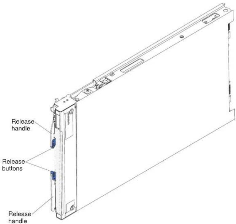
text_image
Release handle Release buttons Release handleAsetofblanklabelsforyourbladeservercomeswiththeBladeCenterchassis. WhenyouinstallthebladeserverintheBladeCenterchassis,writeidentifying informationaboutthebladeserveronalabel.Thenplacethelabelonthe BladeCenterchassisbezel.SeethedocumentationforyourBladeCenterchassisfor recommendedlabelplacement.
Important: Donotplacethelabelonthebladeserveritselforinanywayblock theventilationholesonthebladeserver.
Relateddocumentation
Usethisinformationtoidentifyandlocaterelatedbladeserverdocumentation.
ThisInstallationandUser'sGuidecontainsgeneralinformationabouttheblade server,includinghowtoinstallsupportedoptionaldevicesandhowtoconfigure thebladeserver.Thefollowingdocumentationisalsoavailable:
•ProblemDeterminationandServiceGuide
Thisdocumentcontainsinformationtohelpyousolveproblemsyourself, and it containsinformationforservicetechnicians.
•SafetyInformation
Thisdocumentcontainstranslatedcautionanddangerstatements.Eachcaution anddangerstatementthatappearsinthedocumentationhasanumberthatyou canusetolocatethecorrespondingstatementinyourlanguageintheSafety Informationdocument.
• WarrantyInformation
Thisdocumentcontainsinformationaboutthetermsofthewarranty.
•EnvironmentalNoticesandUserGuide
Thisdocumentcontainstranslatedenvironmentalnotices.
- IntegratedManagementModuleUser'sGuide
ThisdocumentexplainshowtousethefunctionsoftheIMMthatisinstalledin anIBMserver.TheIMMworkswithIBMSystemx ^® ServerFirmwaretoprovide systems-managementcapabilityforSystemxandBladeCenterservers.
- AdvancedManagementModuleUser'sGuide
This document provides information about configuring the advanced management module and managing components that are installed in an IBM Blade Center ^® chassis.
⑧
- AdvancedManagementModuleCommand-LineInterfaceReferenceGuide
Thisdocumentexplainshowtousetheadadvancedmanagementmodule command-lineinterface(CLI)todirectlyaccessBladeCentermanagement functions. The command-line interface alsoprovidesaccesstothetext-console command promptoneachbladeserverthroughaSerialoverLAN(SOL) connection.
- AdvancedManagementModuleMessagesGuide
Thisdocumentprovidesacompletelistofallnon-devicespecificeventsand recommendedactions,sortedbyeventID.Device-specificeventinformationis availableintheProblemDeterminationandServiceGuide.
In addition to the documentation in this library, besuretoreview the Planning and Installation Guide for your Blade Center chassis for information to help you prepare for system installation and configuration.
Tocheckforupdateddocumentation,completethefollowingsteps.
- Gotohttp://www.ibm.com/systems/support/.
- UnderProductsupport, clickBladeCenter.
- Under Popular links, click Publications lookup.
- From the Product family menu, select BladeCenter HX5.
YoucanalsofinddocumentationthatisrelatedtoBladeCenterproductsat http://publib.boulder.ibm.com/infocenter/bladectr/documentation/index.jsp
TheIBMDocumentationCD
TheIBMDocumentationCDcontainsdocumentationforyourbladeserverin PortableDocumentFormat(PDF).ItincludestheIBMDocumentationBrowser to helpyoufindinformationquickly.
YoucanruntheIBMDocumentationCDonanypersonalcomputerthatmeetsthehardwareandsoftwarerequirements.
Hardwareandsoftwarerequirements
Use this information to determine the minimum hardware and software requirements for the bladeserver.
TheIBMDocumentationCDrequiresthefollowingminimumhardwareand software:
•MicrosoftWindowsXP, Windows2000, or RedHat Enterprise Linux5Server
•100MHzmicroprocessor
•32MBofRAM
- AdobeAcrobatReader3.0(orlater)orxpdf, which comes with Linux operating systems
UsingtheDocumentationBrowser
UsetheseinstructionstostarttheDocumentationBrowser.
Use the Documentation Browsertobrowse the content of the CD, read brief descriptions of the documents, and view documents, using Adobe Acrobat Reader or x pdf. The Documentation Browser automatically detect the regional settings in use in your system and display the documents in the language for that region (if available). If a document is not available in the language for that region, the English-language version is displayed.
UseoneofthefollowingprocedurestostarttheDocumentationBrowser:
- If Autostartisenabled, insert the CD into the CD drive. The Documentation Browser starts automatically.
- If Autostartisdisabledorisnotenabledforallusers, useoneofthefollowing procedures:
-If you are using a Windows operating system, insert the CD into the CD or DVD drive and click Start → Run. In the Open field, type e:\win32.bat
whereeisthedriveletteroftheCDorDVDdrive,andclickOK.
-If you are using Red Hat Linux, insert the CD into the CD or DVD drive; then, run the following command from the /mnt /cdrom directory: sh run linux.sh
Select your blade server from the Product menu. The Available Topics list displays allthedocumentsforyourbladeserver.Somedocumentsmightbeinfolders.A plussign(+)indicateseachfolderordocumentthathasadditionaldocuments underit.Clicktheplussigntodisplaytheadditionaldocuments.
When you select a document, a description of the document is displayed under TopicDescription. Toselect more than anonedocument, press and hold the Ctrl key while you select the documents. Click View Book to view the selected document or documents in Acrobat Reader or xpdf. If you selected more than anonedocument, all these selected documents are opened in Acrobat Reader or xpdf.
Tosearchallthedocuments,typeawordorwordstringintheSearchfieldandclickSearch. Thedocumentsinwhichthewordorwordstringappearsarelisted inorderofthemostoccurrences.Clickadocumenttoviewit.PressCtrl+Ftouse theAcrobatsearchfunction,orpressAlt+Ftousethexpdfsearchfunctionwithin thedocument.
ClickHelpfordetailedinformationaboutusingtheDocumentationBrowser.
Noticesandstatementsinthisdocument
Use this information to understand them most common documentation notices and statements and how they are used.
The caution and danger statements in this document are also in them multilingual Safety Information document, which is on the IBM Documentation CD. Each statement is numbered for reference to the corresponding statement in the Safety Information document.
The following notices and statements are used in this document:
•Note: Thesenoticesprovideimportanttips, guidance, or advice.
- Important: These notices provide information or advice that might help you avoid inconvenientorproblemsituations.
- Attention: These notices indicate possible damage to programs, devices, or data. An attention notice is placed just before the instruction or situation in which damage might occur.
- Caution: These statements indicate situations that can be potentially hazardous to you. A caution statement is placed just before the description of a potentially hazardous procedure step or situation.
- Danger: These statements indicate situations that can be potentially lethal or hazardous to you. Adanger statement is placed just before the description of potentially lethal or hazardous procedure step or situation.
Featuresandspecifications
Usehistabletoviewspecificinformationaboutthebladeserver,suchasblade serverhardwarefeaturesandthedimensionsofthebladeserver.
Notes:
-
Power, cooling, removable-mediadrives, externalports, and advanced systems management are provided by the Blade Center chassis.
-
TheoperatingsysteminthebladeservermustprovideUSBsupportforthe bladeserververtorecognizeanduseUSBmediadrivesanddevices.The BladeCenterchassisusesUSBforinternalcommunicationswiththesedevices.
The following table is summary of the features and specifications of the BladeCenterHX5 bladeserver.
Table1.Featuresandspecifications
| Microprocessor:Upto2multi-coreIntelXeonprocessors.Note:UsetheSetuputilitytodeterminethetypeandspeedofthemicroprocessorsinthebladeserver.Memory:16dualinlinememorymodule(DIMM)connectorsType:VeryLowProfile(VLP)double-datarate(DDR3)DRAM.Supports2GB,4GB,8GB,and16GBDIMMswithupto256GBoftotalmemoryonthesystemboardIftwoBladeCenterHX5bladeserversareassembledintoascalablebladecomplex,upto512GBisavailabletothescalablebladecomplex.IftheIBMMAX5isinstalled:Supportsupto40dualinlinememorymodule(DIMM)connectorsforupto640GBoftotalmemory.Note:TheBladeCenterHX5bladeserversupportsmemorysparing.Integratedfunctions:Horizontal-compact-form-factor(CFFh)expansioncardinterfaceVertical-combination-I/O(CIOv)expansioncardinterfaceLocalserviceprocessor:integratedmanagementmodule(IMM)withIntelligentPlatformManagementInterface(IPMI)firmwareIntegratedMatroxG200eVvideocontroller | BroadcomBCM5709Sdual-portGigabitEthernetcontrollerIntegratedkeyboard/video/mouse(cKVM)controllerthroughIMMLightpathdiagnosticsRS-485interfaceforcommunicationwiththemanagementmoduleAutomaticserverrestart(ASR)USB2.0forcommunicationwithcKVMandremovablemediadrives(anexternalUSBportisnotsupported)SerialoverLAN(SOL)WakeonLAN(WOL)Redundantbusesforcommunicationwithkeyboard,mouse,andremovablemediadrivesPredictiveFailureAnalysis(PFA)alerts:MicroprocessorsMemoryElectricalinput:1 2 V dcSize:SingleBladeCenterHX5bladeserver:Height:24.5cm(9.7in)(6U)Depth:44.6cm(17.6in)Width:2.9cm(1.14in)Maximumweight:5.6kg(12.38lb)2BladeCenterHX5bladeserversassembledintoascalablebladecomplex:Height:24.5cm(9.7in)(6U)Depth:44.6cm(17.6in)Width:5.8cm(2.28in)Maximumweight:11.23kg(24.76lb)ABladeCenterHX5bladeservercombinedwithanIBMMAX5expansionblade:Height:24.5cm(9.7in)(6U)Depth:44.6cm(17.6in)Width:5.8cm(2.28in)Maximumweight:9.5kg(21.0lb) | Environment:Airtemperature:-Bladeserveron:10°Cto35°C(50°Fto95°F).Altitude:0 m t o914.4m(0ftto3000ft)-Bladeserveron:10°Cto32°C(50°Fto89.6°F).Altitude:914.4mto2133.6m(3000ftto7000ft)-Bladeserveroff:10°Cto43°C(50°Fto109.4°F).Altitude:914.4mto2133.6m(3000ftto7000ft)-Bladeservershipping:-40°Cto60°C(-40°Fto140°F)Humidity:-Bladeserveron:8%to80%-Bladeserveroff:8%to80%-Bladeserverstorage:5%to80%-Bladeservershipping:5%to100%ParticulatecontaminationAttention:Airborneparticulatesandreactivegasesactingaloneorincombinationwithotherenvironmentalfactorssuchashumidityortemperaturemightposearisktotheserver.Forinformationaboutthelimitsforparticulatesandgases,see"articulatecontamination"onpage122. |
Whatyourbladeserveroffers
Yourbladeserveroffersfeatures,suchastheintegratedmanagementmodule,storagediskdrivesupport,IBM ^® SystemsDirector,IBMEnterpriseX-Architecture ^® , microprocessortechnology,integratednetworksupport,I/Oexpansion,large system-memorycapacity,lightpathdiagnosticsLEDs,PCIExpress ^® ,andpower throttling.
•Integratedmanagementmodule(IMM)
The integrated management module (IMM) combines service processor functions, videocontroller, theremotepresence, and blue-screencapture features in asinglechip. The IMM provides advanced service processor control, monitoring, and alerting function. If an environmental condition exceeds a threshold or if a system component fails, the IMM lights LED stohelp you diagnosethe problem, recordsthe error in the IMM event log, and alerts y out to the problem.
Optionally, the IMMalsoprovidesavirtualpresencecapabilityforremoteserver managementcapabilities. The IMMprovidesremoveservermanagement throughindustry-standardinterfaces:
-IntelligentPlatformManagementInterface(IPMI)version2.0
-SimpleNetworkManagementProtocol(SNMP)version3.0
-CommonInformationModel(CIM)
-Webbrowser.
Formoreinformation,seeChapter6,"AccessingtheIMM,"onpage107.
•DynamicSystemAnalysis(DSA)
IBMDynamicSystemsAnalysis(DSA)collectsandanalysessysteminformation toaidindiagnosingserverproblems.DSAcollectsthefollowinginformation abouttheserver:
-Drivehealthinformation
-EventlogsforServeRAIDcontrollersandserviceprocessors
-Hardwareinventory,includingPCIandUSBinformation
-Installedapplicationsandhotfixes
-Kernelmodules
-Lightpathdiagnosticsstatus
-Networkinterfaceandsettings
-Performancedataanddetailsaboutprocessesthatarerunning
-RAIDandcontrollerconfiguration
-Serviceprocessor(integratedmanagementmodule)statusandconfiguration
-Systemconfiguration
-Vitalproductdataandfirmwareinformation
DSAcreatesaDSAlog,whichisachronologicallyorderedmergeofthe system-eventlog(astheIPMleventlog),theintegratedmanagementmodule (IMM)chassis-eventlog(astheASMeventlog),andtheoperating-systemevent logs.YoucansendtheDSAlogasafiletoIBMserviceorviewtheinformation asatextfileorHTMLfile.
Formoreinformation,seetheProblemDeterminationandServiceGuide.
•Harddiskdrivesupport
The bladeserversupportsuptotwosolidstatedrives(SSDs). You can implement RAID0 or RAID1 for the SSDs.
• IBMServerGuideSetupandInstallationCD
TheServerGuideSetupandInstallationCD, which you can download from the Web, provides program to help you setup the server and install a Windows operating system. The Server Guide program detects installed optional hardware devices and provides the correct configuration programs and device drivers. For more information, see "Using the Server Guide Setup and Installation CD" on page 103.
•IBMSystemsDirector
IBMSystemsDirectorisaplatform-managementfoundationthatstreamlinesthe wayyoumanagephysicalandvirtualsystemsinaheterogeneousenvironment. Byusingindustrystandards,IBMSystemsDirectorsupportsmultipleoperating systemsandvirtualizationtechnologiesforIBMandnon-IBMx86platforms. For moreinformation,seehttp://publib.boulder.ibm.com/infocenter/director/v6r2x/index.jsp.
•IBMEnterpriseX-Architecture
IBMEnterpriseX-Architecturetechnologycombinesproven,innovativeIBM designstomakeyourx86-processor-basedbladeserverpowerful,scalable,and reliable.Formoreinformation,seehttp://www.ibm.com/systems/x/hardware/enterprise/xarchitecture.htm.
•Microprocessortechnology
The bladeserversupportsuptotwomulti-coreIntelXeonmicroprocessors. For more information about supported microprocessors and their part numbers, see the Problem Determination and Service Guide.
Note: The optional microprocessor that IBM supports are limited by the capacity and capability of the server. Anymicroprocessor that you install must have the same specifications asthemicroprocessor that came with the servers.
•Integratednetworksupport
AllbladeservermodelscomewithanintegratedBroadcomdual-portGigabit Ethernetcontroller.Thecontrollersupportsconnectionstoa10Mbps,100Mbps, or1000MbpsnetworkthroughanEthernet-compatibleswitchmoduleinthe BladeCenterchassis.ThecontrolleralsosupportsWakeonLAN ^® technology.
•I/Oexpansion
Thebladeserverhasconnectorsonthesystemboardforoptionalexpansion cardsforaddingmorenetworkcommunicationcapabilitiestothebladeserver.
•Largesystem-memorycapacity
The bladeserversystemboardsupportsupto256GBofsystemmemory.The memorycontrollerprovidessupportforupto16industry-standardregistered ECCDDR3onVeryLowProfile(VLP)formfactorDIMMsinstalledonthe systemboard.ForthemostcurrentlistofsupportedDIMMs,seethe ServerProven® listath:http://www.ibm.com/servers/eserver/serverproven/ compat/us/eserver.htm.
Note: IftwoBladeCenterHX5bladeserversareassembledintoascalableblade complex, upto512GBofsystemmemoryisavailabletothescalableblade complex.
- Serverexpansion
Youcancombinetwobladeserverstogethertoformascalablebladecomplex. ThroughtheadadvancedmanagementmoduleWebinterface,youcanthen configure the scalable blade complex to function as a single hardware partition, whichissingleserverwithuptofourmulti-coremicroprocessorsandupto512 GBofsystemmemory.
Combiningtwobladeserversintoascalablebladecomplexprovidesyouwith implementationflexibilitythroughFlexNodepartitioning.Throughtheadadvanced managementmodule,youcanimplementthescalablebladecomplexasasingle serverorastwoindependentserverswithoutchangingthephysicalsetupofthe bladeservers.Formoreinformationaboutscalablebladecomplexesand
FlexNodepartitioning,see"Workingwithascalablebladecomplex"onpage13.
•Lightpathdiagnostics
Lightpathdiagnosticsprovideslight-emittingdiodes(LEDs)tohelpyou diagnoseproblems. Formoreinformation,seetheProblemDetermination and ServiceGuide.
Inaddition, scalability indicators are available through the front bezel. These indicators enable output to tell whether Blade Center HX5 blades servers are operating independently or as a single hardware partition.
•PCIExpress
PCIExpressisaserialinterfacethatisusedforchip-to-chipinterconnectand expansionadapterinterconnect.Withthebladeexpansionconnector,youcan adoptionII/Oandstoragedevices.
•Powerthrottling
Each bladeserverispoweredbytwoEnterpriseVoltageRegulator-Down (EVRD)11.0voltageregulators.Byenforcingapowerpolicyknownas power-domainoversubscription,theBladeCenterchassiscansharethepower loadbetweenwopowermodulestoensuresufficientpowerforeachdevicein theBladeCenterchassis.Thispolicyisenforcedwhentheinitialpoweris appliedtotheBladeCenterchassisorwhenabladeserverisinsertedintothe BladeCenterchassis.
The following settings forth this policy are available:
-Powermoduleredundancy
-Powermoduleredundancywithbladethrottlingallowed
-Basicpowermanagement
Youcanconfigureandmonitorthepowerenvironmentbyusingtheadvanced managementmodule.Formoreinformationaboutconfiguringandusingpower throttling,seetheAdvancedManagementModuleUser'sGuide(availableat
http://publib.boulder.ibm.com/infocenter/bladectr/documentation/index.jsp
orhttp://www.ibm.com/systems/support/.
Reliability, availability, and serviceability features
Threeofthemostimportantfeaturesinserverdesignarereliability,availability,andserviceability(RAS).TheseRASfeatureshelptoensuretheintegrityofthedatathatisstoredinthebladeserver,theavailabilityofthebladeserverwhenyouneedit,andtheeasewithwhichyoucandiagnoseandcorrectproblems.
ThebladeserverhasthefollowingRASfeatures:
- CustomerupgradeofflashROM-residentcodeanddiagnostics
•Powerpolicy24-hoursupportcenter
•Vitalproductdata(VPD)onmemory
•Processorpresencedetection
- AdvancedConfigurationandPowerInterface(ACPI)
•Automaticserverrestart(ASR)
•Built-indiagnosticsusingDSAPreboot,whichisstoredinintegratedUSB memory.
•Builtinmonitoringfortemperature,voltage,andharddiskdrives
- Customersupportcenter24hoursperday,7daysaweek.
- Customer-upgradeableUnifiedExtensibleFirmwareInterface(UEFI)code and diagnostics
•ECCprotectionontheL2cache - Errorcodesandmessages
•Integratedmanagementmodule(IMM)
•Lightpathdiagnostics
•Memoryparitytesting
•RegisteredECCDDR3memory - Microprocessorbuilt-inself-test(BIST)duringpower-onself-test(POST)
•Microprocessorserialnumberaccess
•PCIPMI2.2
•PCIExpress1.0a
•POST
•ROM-residentdiagnostics - Serviceprocessorthatcommunicateswiththeadvancedmanagementmoduleto enableremotebladeservermanagement
•System-errorlogging
•WakeonLANcapability
•WakeonPCI(PME)capability
•WakeonUSB2.0capability
IBMSystemsDirector
IBMSystemsDirectorisaplatform-managementfoundationthatstreamlinesthe wayyoumanagephysicalandvirtualsystemsinaheterogeneousenvironment.
By using industrystandards, IBMSystemsDirectorsupportsmultipleoperating systems and virtualization technologies in IBM and non-IBMx86 platforms.
Throughasing user interface, IBMSystems Director provides consistent views for viewing managed systems, determining how the systems relate to one another, and identifying their statuses, helping to correlate technical resources with business needs. A set of common task that are included with IBMSystems Director provides many of the core capabilities that are required for basic management, which means instance business value. These common tasks include discovery, inventory, configuration, system health, monitoring, updates, event notification, and automation for managed systems.
The IBMSystemsDirectorwebandcommand-lineinterfacesprovideaconsistent interfacethatisfocusedondrivingthesecommontasksandcapabilities:
•Discovering, navigating, and visualizing systemsonthenetworkwiththe detailedinventoryandrelationshipstotheothernetworkresources
- Notifying users of problem that occur on systems and the ability to isolate sources of the problems
- Notifying users when systems need updates and distributing and installing updates on a schedule
- Analyzing real-timedataforsystemsandsettingcriticalthresholdsthatnotify the administratorofemergingproblems
- Configuringsettingsofasinglesystemandcreatingaconfigurationplanthat canapplythosesettingstomultiplesystems
- Updatinginstalledplug-instoaddnewfeaturesandfunctionstothebase capabilities
•Managingthelifecyclesofvirtualresources
FormoreinformationaboutIBMSystemsDirector,seethedocumentationat http://publib.boulder.ibm.com/infocenter/director/v6r2x/index.jsp,andtheIBM xSeries® SystemsManagementwebsiteathttp://www.ibm.com/systems/management/,whichpresentsanoverviewofIBMSystemsManagementandIBM SystemsDirector.
Majorcomponentsofthebladeserver
Usethisinformationtolocatethemajorcomponentsonthebladeserver.The majorcomponentsofthebladeserverincludefieldreplaceableunits(FRUs), customerreplaceableunits(CRUs), andoptionaldevices.
The following illustrations show sthemajorcomponentsofthebladeserver.
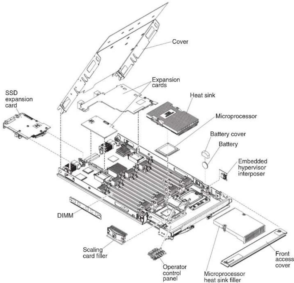
text_image
Cover Expansion cards Heat sink Microprocessor Battery cover Battery Embedded hypervisor interposer SSD expansion card DIMM Scaling card filler Operator control panel Microprocessor heat sink filler Front access coverWorkingwithascalablebladecomplex
YoucanassembletwoBladeCenterHX5bladeserverstogethertocreateascalable bladecomplex.
Ascalablebladecomplexsupportsthefollowingimplementationmodes:
- Single partition. The complex functions as a single server that contains up to fourmulti-coreprocessorsandupto32DIMMs.Whenthecomplexis implementedasasinglehardwarepartition,theleftmostbladeserver(as installedinaBladeCenterchassis)iscalledtheprimarybladeserver.Theblade serverontherightiscalledthesecondarybladeserver.

text_image
Primary blade server Secondary blade server- Multiple partitions (independent partitions). The blade servers are combined intoascalablebladecomplex, but each of the bladeserversissetupasasing partition.
- Stand-alonemode. The bladeserversoperateindependently.
Important: If you install the primary bladeserverofascalablebladecomplex in bladeserverbay7 of a BladeCenter HType8852 chassis, thesecondaryblade server is installed in bladeserverbay8. The primary bladeserverreceives power from powerdomain1 of the chassis and thesecondary bladeserverreceives power from powerdomain2 of the chassis. The following situations can occur if there is a power losstoeitherpowerdomain, depending on how the scalable blade complex is implemented:
- Ifthescalablebladecomplexisimplementedinsinglepartitionmode,alossof powertopowerdomain1orpowerdomain2resultsinbothbladeserversin thescalablebladecomplexgoingdown.
- Ifthescalablebladecomplexisimplementedinstand-alonemode, alossof powertopowerdomain1resultsintheentirescalablebladecomplexgoing down. Alossof powertopowerdomain2resultsinthebladeserverinstalledin bladeserverbay8goingdown, butthebladeserverinstalledin bladeserver bay7continuestofunction.
WithFlexNodeprocessing,youcantogglebetweensinglepartitionmodeand stand-alonemodewithouthavingtomodifythephysicalsetupoftheblade servers.Totogglebetweenmodes,usetheadadvancedmanagementmoduleWeb interface.
Forexample, assumethatyouhavecreatedascalablebladecomplexanddefined thatcomplexasasinglepartitionthroughtheadvancedmanagementmoduleWeb interface:
- Youcantogglethescalablebladecomplextostand-alonemodethroughtheWeb interface.Instand-alonemode,youcaninstalladifferentoperatingsystemoneachbladeserverandrundifferentapplicationsoneachbladeserver.
- Youcanthentogglethebladeservercomplexbacktoasinglepartitionandrun applicationsthattakeadvantagetoupto4processorsand32DIMMs.The operatingsystemthatisinuseistheoperatingsystemoftheprimaryblade server.
- Later, you cant toggle the complex back to stand-alone mode again to gain access to the operating system on these secondary bladeserver.
Singlepartitionmodeconsiderations
The following considerations apply to the blades servers in a scalable blade complex that operates as a single hardware partition:
- AllUEFIsettings(setthroughtheSetuputility)shouldbethesameonboth bladeservers.Iftheyarenot,thesettingsthataredefinedfortheprimaryblade serverreplacetheUEFIsettingsonthesecondaryserver.
Note: When you upgrade the firmware for the blades servers operating in single partition mode, you only have upgraded the primary blades server. The firmware on these secondary blades server is automatically updated. See "Using the Setuputility" on page 72 from more information about the Setuputility.
•The primary bladeserver has access to the SSD son these secondary bladeserver. However, the SSD son the primary bladeserver cannot be combined with the SSD son these secondary bladeserver vertoform a single RAID array. RAID arrays can be formed only using the SSD s within ab bladeserver.
•The primary bladeserver has access to any I/O expansion card that are installed in these secondary bladeserver. However, the I/O expansion cards in the secondary bladeserver cannot be used for a Serial Over LAN connection.
• The primary bladeserver has access to any expansion blades that are installed on these secondary bladeserver.
Important: Anexpansionbladeinstalledonthesecondarybladeservercannot beusedforaSerialOverLANconnection.
- If you press the power button on one bladeserver, both blades servers in the partitioneitherpoweruporpowerdown, depending on the state of the blade servers when you press the power button.
Chapter2.Power,controls,andindicators
Use this information to view power features, turn on and turn off the bladeserver, and view the function of the controls and indicators.
Turningonthebladeserver
AfteryouconnectthebladeservertopowerthroughtheBladeCenterchassis,the bladeservercanbestartedinanyofthefollowingways.
- Youcanpressthepowerbuttononthefrontofthebladeserver(see"Blade servercontrolsandLEDs"onpage16)tosartthebladeserver.Thepower buttonworksonlyiflocalpowercontrolisenabledforthebladeserver.Local powercontrolisenabledanddisabledthroughtheadvancedmanagement moduleWebinterface.
Notes:
-
WaituntilthepowerLEDonthebladeserverflashesslowlybeforeyoupress thepowerbutton.Whiletheserviceprocessorinthebladeserveris initializingandsynchronizingwiththeadadvancedmanagementmodule,the power-onLEDflashesrapidly,andthepower-controlbuttonontheblade serverdoesnotrespond.Thisprocesscantakeapproximately90seconds afterthebladeserverhasbeeninstalled.
-
Whilethebladeserverisstarting, thepowerLEDonthefrontoftheblade serverislitanddoesnotflash.See"BladeservercontrolsandLEDs"on page16forthepowerLEDstates.
- Ifapowerfailureoccurs, theBladeCenterchassisandthebladeservercanbe configuredthroughtheadadvancedmanagementmoduleWebinterfacetostart automaticallywhenpowerisrestored.
- Youcanturnonthebladeserverthroughtheadadvancedmanagementmodule Webinterface.Formoreinformationabouttheadadvancedmanagementmodule Webinterface,seetheIBMBladeCenterAdvancedManagementModule:User's Guide.
- YoucanturnonthebladeserverthroughtheWakeonLANfeature.Theblade servermustbeconnectedtopower(thepower-onLEDisflashingslowly),the bladeservermustbecommunicatingwiththeadvancedmanagementmodule, theoperatingsystemmustsupporttheWakeonLANfeature,andtheWakeon LANfeaturemustbeenabledthroughtheadvancedmanagementmodule interface.
Note: Procedure to enable the Wakeon LAN feature varies depending on the network device. Referto the documentation that is provided for your network device form more information.
Turningoffthebladeserver
Whenyouturnoffthebladeserver,itisstillconnectedtopowerthroughthe BladeCenterchassis.Thebladeservercanrespondtorequestsfromtheservice processor,suchasaremoterequesttoturnonthebladeserver.Toremoveall powerfromthebladeserver,youmustremoveitfromtheBladeCenterchassis.
Beforeyouturnoffthebladeserver,shutdowntheoperatingsystem.Seethe operating-systemdocumentationforinformationaboutshuttingdownthe operatingsystem.
Thebladeservercanbeturnedoffinanyofthefollowingways:
- Youcanpressthepowerbuttononthebladeserver(see"Bladeservercontrols and LEDs").Pressingthebuttonstartsanorderlyshutdownoftheoperating system,ifthisfeatureissupportedbytheoperatingsystem.
- If the operating system stops functioning, you can press and hold the power button form more than 4 second to turn off the blades server.
Attention: Pressing the button for 4 seconds force the operating system to shutdown immediately. Datalossis possible.
- Youcanturnoffthebladeserverthroughtheadadvancedmanagementmodule webinterface.Formoreinformationabouttheadadvancedmanagementmodule webinterface,seetheIBMBladeCenterAdvancedManagementModule:User's Guide.
BladeservercontrolsandLEDs
Use this information for details about the controls and LEDs on the blades server and IBM MAX5 expansion blade.
The following illustration identifies the buttons and LEDsonthebladeserver control panel.

text_image
NMI button Power button / LED KVM select button / LED Media tray select button / LED MT IBM Activity LED Location LED Information LED Fault LEDNMIbutton(recessed)
Thenonmaskableinterrupt(NMI)dumpsthepartition. Use this recessed buttononlyasdirected by IBMSupport.
Note: You can also send an NM event to these selected blades server remotely using the AMM. Referto the Blade Center Advanced Management Module User's Guide for information pertaining to the proper installation and configuration of Java, operating systems, and browser that are supported for remote access.
Powerbutton/LED
Whenthebladeserverhaspower, pressthisbuttontoturnonorturnoff thebladeserver.
Note: The power button work only if local power control is enabled for the bladeserver. Local power control is enabled and disabled through the advanced management module web interface.
Afterthebladeserverisremovedfromthechassis,pressthisbuttonto activatethesystemboardLEDs(lightpathdiagnostics).SeetheProblem DeterminationandServiceGuideformoreinformation.
ThisbuttonisalsothepowerLED. ThisgreenLED indicate the power status of the bladeserver:
- Flashingrapidly: TheLEDflashesrapidlyforoneofthefollowing reasons:
-Thebladeserverhasbeeninstalledinachassis.Whenyouinstallthe bladeserver,theLEDflashesrapidlyforupto90secondswhilethe integratedmanagementmodule(IMM)onthebladeserveris initializingandsynchronizingwiththeadvancedmanagement module.
-The bladeserverdoesnothavepowerpermissionsassignedtoit throughtheadvancedmanagementmodule.
-TheBladeCenterchassisdoesnothaveenoughpowertoturnonthe bladeserver.
-TheIMMonthebladeserverisnotcommunicatingwiththe advancedmanagementmodule.
- Flashing slowly: The blade server has power and is ready to be turned on.
•Litcontinuously:Thebladeserverhaspowerandisturnedon.
Whenthebladeserverison, pressing this button causes an orderly shutdown of the bladeservers or that it's safet remove. This includes shutting down the operating system (if possible) and removing power from the bladeserver.
Note: If you press the power button on the bladeserver that is part of a scalable blade complex running as single partition, both bladeservers in the partition power or shutdown.
Ifanoperatingsystemisrunning,youmighthavetopressthebuttonfor approximately4secondstoinitiatetheshutdown.
Attention: Pressing the button for 4 seconds force the operating system to shutdown immediately. Datalossis possible.
KVMselectbutton/LED
PressthisbuttontoassociatethesharedBladeCenterchassiskeyboard, video,andmouse(KVM)portswiththebladeserver.TheLEDonthis buttonflasheswhiletherequestisbeingprocessedandthenislitwhenthe ownershipofthekeyboard,video,andmousehasbeentransferredtothe bladeserver.Itcantakeapproximately20secondstoswitchthekeyboard, video,andmousecontroltothebladeserver.
Usingakeboardthatisdirectlyattachedtotheadadvancedmanagement module,youcanpresskeyboardkeysinthefollowingsequencetoswitch KVMcontrolbetweenbladeserversinsteadofusingtheKVMselect button:
NumLockNumLockblade_server_numberEnter
Whereblade_server_numberisthetwo-digitnumberofthebladeserver bayinwhichthebladeserverisinstalled.Abladeserverthatoccupies morethanonebladeserverbayisidentifiedbythelowestbaynumber thatitoccupies.
If there is no response when you press the KVM select button, you can use the advanced management module web interface to determine whether local control has been disabled on the bladeserver. See the IBM Blade Center Advanced Management Module: User's Guide to more information.
Notes:
- TheoperatingsysteminthebladeservermustprovideUSBsupportfor thebladeservertorecognizeandusethekeyboardandmouse,evenif thekeyboardandmousehavePS/2-styleconnectors.
- If you install as supported Microsoft Windows operating system on the bladeserver while it is not the current owner of the keyboard, video, and mouse, adelay of upto 1 minute occurs the first timethat you switch the keyboard, video, and mouseto the bladeserver. All subsequent switching takes place in then normal KVM switching time frame (upto 20 seconds).
Mediatrayselectbutton/LED
PressthisbuttontoassociatethesharedBladeCenterchassismediatray (removable-mediadrives)withthebladeserver.TheLEDonthebutton flasheswhiletherequestisbeingprocessedandthenislitwhenthe ownershipofthemediatrayhasbeentransferredtothebladeserver.Itcan takeapproximately20secondsfortheoperatingsysteminthebladeserver torecognizethemediatray.
If there is no response when you press the media-tray select button, you can use the advanced management module web interface to determine whether local control has been disabled on the bladeserver.
Note: The operating system in the bladeserver must provide USB support for the bladeserver to recognize and use a theremovable-mediated drives.
ActivityLED
WhenthisgreenLEDislit(flashing), it indicates that there is activity on thenetworkorexternalstoragedevice.
LocationLED
ThesystemadministratorcanremotelyturnonthisblueLEDtoaidin visuallylocatingthebladeserver.WhenthisLEDislit,thelocationLED ontheBladeCenterchassisalsolit.ThelocationLEDcanbeturnedon andoffthroughtheadvancedmanagementmodulewebinterfaceor throughIBMSystemsDirector.Formoreinformationabouttheadvanced managementmodulewebinterface,seetheIBMBladeCenterAdvanced ManagementModule:User'sGuide.FormoreinformationaboutIBMSystems Director,seethedocumentation,whichisavailableathttp://publib.boulder.ibm.com/infocenter/director/v6r2x/index.jsp.
InformationLED
WhenthisamberLEDislit, it indicates that an Automatic BIOS recovery (ABR) has occurred. The bladeserverstart supusing the backup UEFI image. Seethe Problem Determination and Service Guide
TheinformationLEDcanbeturnedoffthroughtheadadvancedmanagement moduleCLI,SNMP,orwebinterfacesorthroughIBM ^® SystemsDirector. Formoreinformationabouttheadadvancedmanagementmoduleweb
interface,seetheIBMBladeCenterAdvancedManagementModule:User's
Guide.FormoreinformationaboutIBMSystemsDirector,seethe documentation,whichisavailableathttp://publib.boulder.ibm.com/infocenter/director/v6r2x/index.jsp.
FaultLED
WhenthisamberLEDislit, it indicates that a system error has occurred in the bladeserver. In addition, the fault LED on the chassis system LED panel is lit. Seethe Problem Determination and Service Guide
The fault LED turn soffonly after the error is corrected.
Note: WhenthefaultLEDturnsoff, you should also clear the IMMevent log. Use the Setup utility to clear the IMMevent log.
IBMMAX5LEDs
WhenthereisafaultontheIBMMAX5expansionblade,thefrontbezelofthe IBMMAX5expansionbladewillappeartohaveanorangeglow.Youcanpressthe lightpathbuttononthesystemboardoftheIBMMAX5expansionbladeto determinewhichLEDsarelit.
Note: If there is an orangeglow, it will be referred to as MEU (Memory Expansion Unit) Fault in the system event log.
The following LEDs are available on the IBMMAX5 expansion bladelightpath diagnostic panel:
SeeLightPathBelow(LP1)
ThisamberLEDindicates that there is a problem with the Blade Center HX5 to which the IBM MAX5 expansion bladewas attached. If this LED is lit, complete the following steps:
-
RemovetheIBMMAX5expansionblade(see"RemovinganIBM MAX5"onpage30).
-
PressthepowerbuttonontheBladeCenterHX5bladeserverto determinewhichLEDsarelitonthebladeserver.
TheSeeLightPathBelow(LP1)LEDisreferredtoasMEULookBelowin thesystemeventlog.
SystemBoard(SBRD)
ThisamberLEDindicates that there is a problem with the system board. If this amber LED dislit, complete the following steps:
- InstalltheIBMMAX5(see"InstallinganIBMMAX5" onpage62).
-
InstalltheBladeCenterHX5inthechassis(see"Installingablade serverinaBladeCenterchassis" onpage68).
-
Restartthebladeserver.
-
If the problem remains, replacethesystemboard on the IBMMAX5 (seethe Problem Determination and Service Guide for instructions).
TheSystemBoard(SBRD)LEDisreferredtoasMEUErrorinthesystem eventlog.
Lightpathpower(LP2)
ThisamberLEDindicates that toneormore LEDs are lit on the IBMMAX5 systemboard..
TheLightpathpower(LP2)LEDisreferredtoasMEULEDPowerinthe systemeventlog.
SeetheProblemDeterminationandServiceGuide
Scalabilityindicators
TheBladeCenterHX5bladeserverprovidesscalabilityindicators, which are viewablethroughthefrontbezelofthebladeserverwhenitisinstalledina BladeCenterchassis.Thescalabilityindicatorsremainlituntilthebladeserveris started.
TheBladeCenterHX5bladeservercanbedeployedasastand-alonebladeserver. ItcanalsobecombinedwithanotherBladeCenterHX5bladeservertoforma scalablebladecomplex.WhentwoBladeCenterHX5bladeserversarecombined intoascalablebladecomplex,youcanspecifythattheyoperateasasing hardwarepartitionoroperateinstand-alonemode.
Thescalability indicatorshowwhetheraBladeCenterHX5bladeserverisa stand-alonebladeserveroranodeinascalablebladecomplexoperatingasa singlehardwarepartition.
WhenaBladeCenterHX5bladeserverisastand-alonebladeserver, thescalability indicatorscontinuallymoveupanddownthefrontofthebezel.

text_image
LEDsWhenaBladeCenterHX5bladeserverispartofthescalablebladecomplex operatinginsinglepartitionmode,thescalabilityindicatorsmoveupthefirst bladeserver,crossovertothesecondbladeserver,andthenmovedownthe secondbladeserver.
Note: If you have setup a scalable blade complex in single partition mode but when you start the blades servers, the scalability indicators foreach blades server seem to be operating independently, there might be a problem with the configuration of the scalable blade complex.

text_image
LEDsBladeserverconnectors-BladeCenterHX5
Use this information to locate blades serversystemboard components and connectors for optional devices.
The following illustrations show sthesystemboard components, including connectors for user-installable optional devices, in the bladeserver.
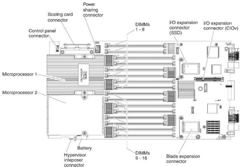
text_image
Scaling card connector Power sharing connector Control panel connector DIMMs 1 - 8 I/O expansion connector (SSD) I/O expansion connector (CIOv) Microprocessor 1 Microprocessor 2 Battery Hypervisor interposer connector DIMMs 9 - 16 Blade expansion connectorNote: The optional SSD expansion card is installed in the I/O expansion connector (SSD).
Bladeserverconnectors-IBMMAX5
UsethisinformationtolocatetheIBMMAX5expansionbladeconnectors.
The following illustrations show the system board components, including connectors for user-installable optional devices, in the IBMMAX5 expansion blade.
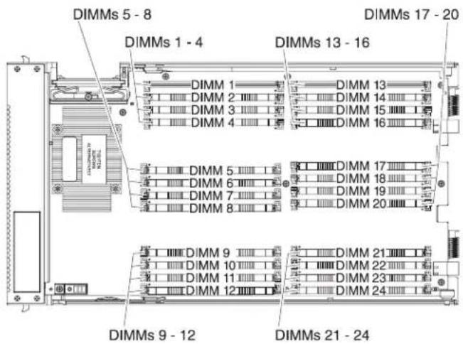
text_image
DIMMs 5 - 8 DIMMs 1 - 4 DIMMs 17 - 20 DIMMs 13 - 16 DIMM 1 DIMM 13 DIMM 2 DIMM 14 DIMM 3 DIMM 15 DIMM 4 DIMM 16 DIMM 5 DIMM 17 DIMM 6 DIMM 18 DIMM 7 DIMM 19 DIMM 8 DIMM 20 DIMM 9 DIMM 21 DIMM 10 DIMM 22 DIMM 11 DIMM 23 DIMM 12 DIMM 24 DIMMs 9 - 12 DIMMs 21 - 24Input/outputconnectorsanddevices
Theinput/outputconnectorsthatareavailabletothebladeserveraresuppliedby theBladeCenterchassis.SeethedocumentationthatcomeswiththeBladeCenter chassisforinformationabouttheinput/outputconnectors.
The bladeserverhastwoselectionbuttonsonthecontrolpanel:themediatray selectbuttonandthekeyboard/video/mouseselectbutton.See"Bladeserver controlsandLEDs"onpage16forinformationaboutthesebuttonsandtheir functions.
TheEthernetcontrollersthebladeservercommunicatewiththenetwork throughtheEthernet-compatibleI/OmodulesintheBladeCenterchassis.Network signalstoandfromthebladeserveroranyexpansioncardsareautomatically routedtoasame-network-interfaceI/Omodulethroughcircuitryinthe BladeCenterchassis.
Chapter3.Installingoptionaldevices
Use this information for instructions about installing optional hardware devices in the bladeserver and assembling bladeservers into a scalable blade complex. Some device-removal instructions are provided in case you have to remove one device to install another.
Note: If you are installing devices in a scalable blade complex, rememberto install them in both Blade Center HX5 blades servers in the complex.
Installationguidelines
Usetheseguidelinesbeforeyouinstallthebladeserveroroptionaldevices.
- Beforeyoubegin,read"Safety"onpagevand"Handlingstatic-sensitive devices"onpage24.Thisinformationhelpsyouworksafely.
- When you install your new blades server, take the opportunity to download and apply them most recent firmware updates. This step helps ensure that any known issues are addressed and that your blades server is ready to function at maximum level sof performance.
- Observegoodhousekeepingintheareawhereyouareworking.Placeremoved coversandotherpartsinasafeplace.
- Backupallimportantdatabeforeyoumakechangestodiskdrives.
- Before you remove abladeserver from the Blade Center chassis, you must shut down the operating system and turn off the bladeserver. You donot need to shutdown the chassis itself.
- Blueonaccomponentindicatestouchpoints,whereyoucangripthecomponent toremoveitfromorinstallitinthebladeserver,openorclosealatch,andso on.
•Foralistofsupportedoptionaldevicesforthebladeserver,see http://www.ibm.com/servers/eserver/serverproven/compat/us/eserver.htm.
Systemreliabilityguidelines
Usetheseguidelinestoensurethatthebladeservermeetsthepropercoolingand systemreliabilityrequirements.
- Toensurepropercooling, donotoperatetheBladeCenterchassiswithouta bladeserverorbladefillerinstalledineachbladeserverbay. Seethe documentation for your BladeCenterchassis for additional information.
- Each microprocessor socket always contain either a microprocessor dust cover and heatsink filler or a microprocessor and heatsink. If the bladeserver has only onemicroprocessor, it must be installed in microprocessor socket 1.
- Makesurethattheventilationholesonthebladeserverarenotblocked.
- The bladeserverbatterymustbeoperational. If the battery becomes defective, replace it immediately. For instructions, seethe Problem Determination and Service Guide.
Handlingstatic-sensitivedevices
Toreducethepossibility of damage from electrostatic discharge, observethese precautions.
Attention: Staticelectricity candamagethebladeserverandotherelectronic devices. To avoid damage, keep static-sensitive devices in their static-protective packages until you are ready to install them.
- WhenyouworkonaBladeCenterchassisthathasanelectrostaticdischarge (ESD)connector,useawriststrap,especiallywhenyouhandlemodules, optionaldevices,orbladeservers.Toworkcorrectly,thewriststrapmusthavea goodcontactatbothends(touchingyourskinatoneendandfirmlyconnected totheESDconnectoronthefrontorbackoftheBladeCenterchassis).
- Limityourmovement.Movementcancausestaticelectricitytobuilduparound you.
- Handlethedevicecarefully, holdingitbyitsedgesoritsframe.
- Donottouchsolderjoints,pins,orexposedcircuitry.
- Donotleavethedevicewhereotherscanhandleanddamageit.
- While the device is still in its static-protective package, touch it to an unpainted metalpartoftheBladeCenterchassisoranyunpaintedmetalsurfaceonany othergroundedrackcomponentintherackinwhichyouareinstallingthe deviceforatleast2seconds.Thisdrainsstaticelectricityfromthepackageand fromyourbody.
- Removethedevicefromitspackageandinstallitdirectlyintothebladeserver withoutsettingdownthedevice.Ifitisnecessarytosetdownthedevice.putit backintoitsstatic-protectivepackage.Donotplacethedeviceontheblade servercoveroronametalsurface.
•Takeadditionalcarewhenyouhandledevicesduringcoldweather.Heating reducesindoorhumidityandincreasesstaticelectricity.
RemovingthebladeserverfromtheBladeCenterchassis
UsetheseinstructionstoremoveaBladeCenterHX5bladeserverorascalable bladecomplexfromaBladeCenterchassis.
The following illustrations show show to remove a BladeCenter HX5 bladeserver from achassis.

natural_image
Technical line drawing of a server rack with internal fan array and directional arrows indicating assembly (no text or symbols)Attention:
- Tomaintainpropersystemcooling, donotoperatetheBladeCenterchassis withoutabladeserverorfillermoduleinstalledineachbladeserverbay.
- Whenyouremovethebladeserver,notethebladeserverbaynumber. Reinstallingabladeserverintoadifferentbladeserverbayfromtheoneitwas removedfromcanhaveunintendedconsequences.Someconfiguration informationandupdateoptionsareestablishedaccordingtobladeserverbay number.Ifyoureinstallthebladeserverintoadifferentbay,youmightneedto reconfigurethebladeserver.
ToremoveaBladeCenterHX5bladeserverorscalablebladecomplex,complete thefollowingsteps:
- Before you begin, read "Safety" on page and "Installation guidelines" on page 23.
- Ifthebladeserverisoperating, shutdowntheoperatingsystem.
- Pressthepowerbuttontoturnoffthebladeserver(see "Turningofftheblade server" onpage15for moreinformation).
Note: If the bladeserverispartofascalablebladecomplexoperatinginsingle partitionmode, pressing the power button on one blade server causes both bladeserverstoshutdown.
- Openthetworeleasehandlesasshownintheillustration.Thebladeserver movesoutofthebladeserverbayapproximately0.6cm(0.25inch).
- Pullthebladeserveroutofthebay.
- Installeitherabladefilleroranotherbladeserverinthebladeserverbay within1minute.
Removingthebladeservercover
Usetheseinstructionstoopenandremovethecoverfromabladeserverorfromthetopmostbladeserverinascalablebladecomplex.
Toopenandremovethebladeservercover,completethefollowingsteps.
- Before you begin, read "Safety" on page and "Installation guidelines" on page 23.
- Carefully lay the bladeserverona flat, static-protectives surface, orienting the bladeserver with the bezelpointing toward you.
- Pressthebladeservercoverreleaseoneachsideofthebladeserver,topmost bladeserverinascalablebladecomplex,orexpansionunit,andliftthecover awayfromthebladeserver,asshowninthefollowingillustration.
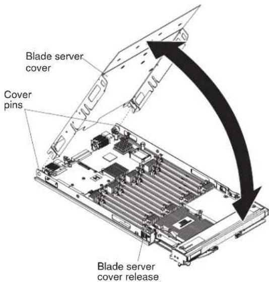
text_image
Blade server cover Cover pins Blade server cover release- Laythecoverflatorstoreitforfutureuse.
Statement12

CAUTION: The following label indicates ahotsurfacenearby.

Statement21

CAUTION: Hazardousenergyispresentwhenthebladeserverisconnectedtothepower source.Alwaysreplacethebladecoverbeforeinstallingthebladeserver.
Disassemblingascalablebladecomplex
Ifthescalablebladecomplexcamepreassembled,youmustdisassembleittoadd componentstoeachofthebladeserversinthescalablebladecomplex.
Note: This procedure assumes that you are disassembling scalable blade complex to install components since each of the blades servers but that you will assemble the bladeserverback into a scalable blade complex. If you are disassembling the scalable blade complex, you set the blades servers as independent, stand-alone blade servers, see the Problem Determination and Service Guide.
Todisassembleascalablebladecomplex,completethefollowingsteps.
-
Before you begin, read "Safety" on page and "Installation guidelines" on page23.
-
Removethecoverfromthetopmostbladeserver(see"Removingtheblade servercover"onpage25forinstructions).
-
Ifablaeexpansionunitisinstalled,removeit(see"Removinganexpansion unit"onpage32).
-
Standthebladeserversuprightonaclean,flatworksurface,withthe2-node scalabilitycardfacingup.
-
Releasethelowerhandles(rotatethelowerhandlesdown)toallowtheblade serverstositflatontheworksurface

natural_image
Technical line drawing of a mechanical or electronic component with mounting brackets and connectors (no text or symbols)-
Removethe2-nodescalabilitycard(see "Renovingthe2-nodescalabilitycard" onpage28forinstructions).
-
Pressthebladeservercoverreleaseoneachsideofthebladeserverandliftthe topmostbladeserverfromthebottombladeserverasshowninthefollowing illustration.
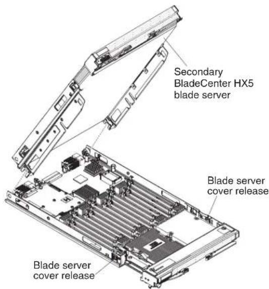
text_image
Secondary BladeCenter HX5 blade server Blade server cover release Blade server cover releaseRemovingthe2-nodescalabilitycard
Usethisinformationtoremovethe2-nodescalabilitycardfromabladeserver.
Toremovethe2-nodescalabilitycard,completethefollowingsteps:
-
Before you begin, read "Safety" on page and "Installation guidelines" on page23.
-
Looseneachscrewonthe2-nodescalabilitycard,usingtheprovided3/16"hex driver.Alternatethelooseningofeachscrewuntilbothscrewsareremoved.
-
Liftthe2-nodescalabilitycardoffbothbladeserversandstorethecardina safeplace.
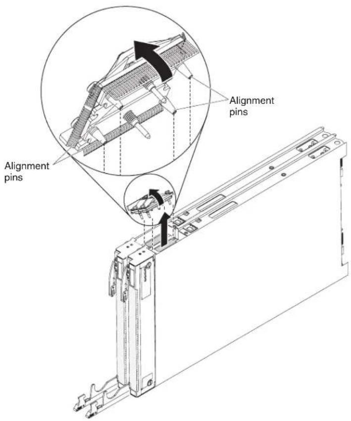
text_image
Alignment pins Alignment pinsNote: When you removethe2-nodescalability card, the Blade Center HX5 bladeserversarenolongerscaled; each bladeserveroperates independently in achassis.
RemovingtheIBMMAX51-nodeScalabilitycard
UsethisinformationtoremovetheIBMMAX51-nodescalabilitycardfromablade server.
ToremovetheIBMMAX51-nodescalabilitycard,completethefollowingsteps.
- Before you begin, read "Safety" on page and "Installation guidelines" on page23.
- Looseneachscrewonthe1-nodescalabilitycard,usingtheprovided3/16"hex driver.Alternatethelooseningofeachscrewuntilbothscrewsareremoved.
- Liftthe1-nodescalabilitycardoffofthebladeserverandexpansionbladeandstorethecardinasafeplace.

text_image
Alignment pins Alignment pinsRemovinganIBMMAX5
UsetheseinstructionstoremoveanIBMMAX5.
ToremoveanIBMMAX5,completethefollowingsteps:

text_image
IBM MAX5 Blade server cover release Upper ridge Power jumper Blade server cover release- Before you begin, read "Safety" on page and "Installation guidelines" on page 23.
- Carefully lay the bladeserverona flat, static-protectives surface.
- RemovetheIBMMAX51-nodescalabilitycard(see"RemovingtheIBMMAX51-nodeScalabilitycard"onpage29forInstructions).
- RemovetheIBMMAX5:
a. Pressthebladeservercoverreleaseoneachsideofthebladeserverandlift theIBMMAX5fromthebladeserver.
b. RotatetheIBMMAX5open;then,lifttheIBMMAX5fromthebladeserver.
- Complete following stepsify you are not going to install another IBMMAX5 expansion blade:
Note: TouseaBladeCenterHX5bladeserverthathastallheatsinks, you must installanotherTBMMAX5expansionblade.
a. LocatethepowersharingconnectorontheBladeCenterHX5bladeserver andinstallthepowersharingcover(see"Bladeserverconnectors-BladeCenterHX5" onpage21).
b. RemovetheEMCgasketfromtheupperridgeofthe"Bladeserver connectors-BladeCenterHX5"onpage21bladeserverifoneisinstalled.
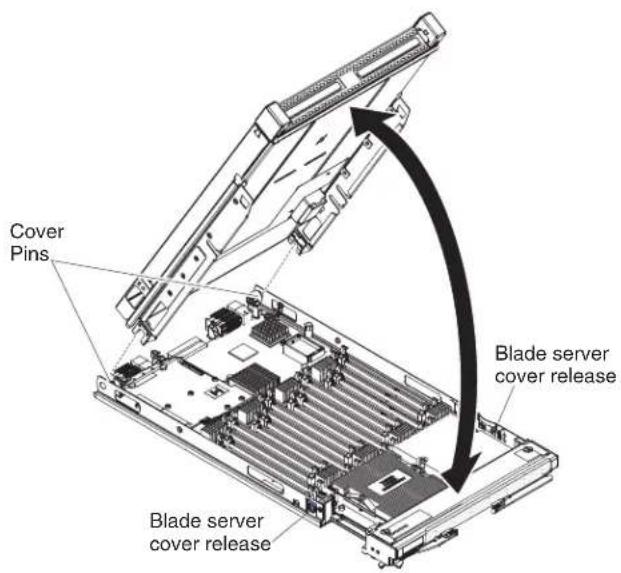
Installinganexpansionunit
Usetheseinstructionstoinstallanexpansionunitorforthetopmostbladeserver inascalablebladecomplex.
Attention: You cannot insert the blades server into the Blade Center chassis until the cover is installed and closed. Donot attempt to overridethis protection.
Statement21

CAUTION:
Hazardousenergyispresentwhenthebladeserverisconnectedtothepower source.Alwaysreplacethebladecoverbeforeinstallingthebladeserver.

text_image
Cover Pins Blade server cover release Blade server cover releaseToinstallandclosethebladeservercover,completethefollowingsteps:
-
Before you begin, read "Safety" on page and "Installation guidelines" on page 23.
-
Carefully lay the bladeserverona flat, static-protectives surface, orienting the bladeserver with the bezelpointing toward you.
-
Locatethebladeexpansionconnectorandremovethecoverifoneisinstalled (see 'Bladeserverconnectors-BladeCenterHX5" onpage21).
-
Touchthestatic-protectivepackagethatcontainstheoptionalexpansionunitto any unpainted metal surface on the BladeCenter unit or any unpainted metal surfaceonanyothergroundedrackcomponent;then,removetheoptional expansionunitfromthepackage.
-
Orienttheoptionalexpansionunitasshownintheillustration.
-
Lowertheexpansionunitsothattheslotsattherearslidedownontothecover pinsattherearofthebladeserver;then,pivottheexpansionunitdownonto thebladeserver.
-
Iftheexpansionunithasacoveralreadyinstalled,removeit(seeRemovingthe bladeservercover).
-
InstallthebladecoverfromtheBladeCenterHX5(seeInstallingtheblade servercover).
Important:TheBladeCenterHX5bladecovercontainsthesystem-servicelabel onthebottomofthecover.
- InstallthebladeserverorscalablebladecomplexintotheBladeCenterchassis (seeInstallingabladeserverinaBladeCenterchassisforinstructions).
Removinganexpansionunit
Usetheseinstructionstoremoveanexpansionunitfromabladeserverorfromthe topmostbladeserverinascalablebladecomplex.
text_image
Cover Pins Blade server cover release Blade server cover releaseToopenandremoveanexpansionunit,completethefollowingsteps.
-
Before you begin, read "Safety" on page and "Installation guidelines" on page 23.
-
IfthebladeserverorscalablebladecomplexisinstalledinaBladeCenter chassis,removeit.SeeRemovingthebladeserverfromtheBladeCenterchassis forinstructions.
-
Carefully lay the bladeserverona flat, static-protectives surface, orienting the bladeserver with the bezelpointing toward you.
-
Openthebladeservercover(see "Removingthebladeservercover" on page 25 for instructions).
-
Pressthebladeservercoverreleaseoneachsideofthebladeserverandliftthe expansionunitfromthebladeserver.
-
Rotatetheexpansionbladeopen;then,lifttheexpansionbladefromtheblade server.
-
If additionalexpansionunitsneedtoberemoved,repeatsteps5and6.
-
If you are instructed to return the expansion unit, follow all packaging instructions, and use an app packaging materials for shipping that a resupplied to you.
Important: Donotreturnthebladecover. You will need to install the blade cover from the BladeCenterHX5 onto thenewexpansion unit. The BladeCenterHX5 blade cover contains the system-specific label on the bottom of the cover.
Statement12

CAUTION:
The following label indicates ahotsurfacenearby.

Statement21

CAUTION:
Hazardousenergyispresentwhenthebladeserverisconnectedtothepower source.Alwaysreplacethebladecoverbeforeinstallingthebladeserver.
InstallingaDIMM-IBMMAX5
Theexpansionbladehasatotalof24dualinlinememorymodule(DIMM) connectors.Theexpansionbladesupports2GB(Type7873models),4GB,8GB, and16GB(Type7873models)memoryDIMMs.Typically,youwillinstall memorysupportedbytheBladeCenterHX5bladeserverbeforeinstallingmemory intheIBMMAX5expansionblade.
There are two versions of the IBM MAX5 expansion blade, referred to the IBM MAX5 version 1 and IBM MAX5 version 2 in this document. IBM MAX5 version 2 has a "MAX5" identifying label on the bottom of the front bezel. The functionality of the two IBM MAX5 expansion blades are equivalent except the type of DIMMs supported. The type of DIMM supported will differ, depending on the version of IBM MAX5 expansion blade installed.
Note: To ensure that all memory installed in the IBM MAX5 expansion blade is recognized by UEFI, makes sure that you install a minimum of 2 DIMMs in the Blade Center HX5 bladeserver.
DependingonthememorymodethatissetintheSetuputility,theexpansion bladecansupportaminimumof4GBandamaximumof384GBofsystem memory.ForacurrentlistofsupportedDIMMsfortheexpansionblade,see http://www.ibm.com/servers/eserver/serverproven/compat/us/eserver.html
MemorymustbeinstalledinpairsofDIMMs. Observethefollowingruleswith populatingtheIBMMAX5expansionblade:
Table2.DIMMpopulationrules
| DIMMGroupingAAllDIMMsinthisgroupmustbethesametechnology(DRAMsize,suchas2Gbit) | ||
| DIMM1,DIMM8 | DIMM2,DIMM7AllDIM | MMsmustbethesameDRAMwidth(such as4Rx8) |
| DIMM3,DIMM6 | DIMM4,DIMM5AllDIM | MMsmustbethesameDRAMwidth(such as4Rx8) |
| DIMMGroupingBAllDIMMsinthisgroupmustbethesametechnology(DRAMsize,suchas2Gbit) | ||
| DIMM13, DIMM17 | DIMM14,DIMM18AllD | DIMMsmustbethesameDRAMwidth(such as4Rx8) |
| DIMM15, DIMM19 | DIMM16,DIMM20AllD | DIMMsmustbethesameDRAMwidth(such as4Rx8) |
| DIMMGroupingCAllDIMMsinthisgroupmustbethesametechnology(DRAMsize,suchas2Gbit) | ||
| DIMM9,DIMM21 | DIMM10,DIMM22AllD | DIMMsmustbethesameDRAMwidth(such as4Rx8) |
| DIMM11, DIMM23 | DIMM12,DIMM24AllD | DIMMsmustbethesameDRAMwidth(such as4Rx8) |
Notes:
•EachDIMMpairmustbetheexactsamesizeandspeed. Forexample, DIMM1 and DIMM8 mustbethesamesizeandspeed. DIMM2 and DIMM7 must be the samesizeandspeed. However, DIMM1 and DIMM2 havetobethesame technology, but they donotneed to be the samesizeandspeed.
- WhenpopulatingtheIBMMAX5,usetheDIMMswiththegreatestsizefirst. For example,install8GBDIMMsbeforeyouinstall4GBDIMMs.Populatethe DIMMsaccordingtotheDIMMpopulationtableforyourenvironment.See Table3throughTable5onpage35fortheDIMMpopulationorder.
The installation order for DIMMs depends on whether you intend to optimize the DIMM installation for performance or for powersaving.
The following table lists the memory configurations and installation order to optimize the IBMMAX5 for performance.
Table3. Systemmemoryconfigurationforperformance
| Installed memory | DIMMconnector | |||||||||||||||||||||||
| 1 | 2 | 3 | 4 | 5 | 6 | 7 | 8 | 9 | 1 | 0 | 1 | 1 | 1 | 2 | 1 | 3 | 1 | 4 | 1 | 5 | 1 | 6 | 1 | |
| 2DIMMsXX | ||||||||||||||||||||||||
| 4DIMMsXX | X | X | ||||||||||||||||||||||
| 6DIMMsXX | X | X | XX | |||||||||||||||||||||
| 8 DIMMs | X | X | X | X | X | X | X | X | ||||||||||||||||
| 10 DIMMs | X | X | X | X | X | X | X | X | X | X | ||||||||||||||
| 12 DIMMs | X | X | X | X | X | X | X | X | X | X | X | X | ||||||||||||
| 14 DIMMs | X | X | X | X | X | X | X | X | X | X | X | X | X | X | ||||||||||
| 16 DIMMs | X | X | X | X | X | X | X | X | X | X | X | X | X | X | X | X | ||||||||
| 18DIMMsX | XXX | XXX | X | X | X | X | X | X | X | X | X | X | X | |||||||||||
| 20DIMMsX | X | X | X | X | X | X | X | X | X | X | X | X | X | X | X | X | X | X | ||||||
| 22DIMMsX | X | X | X | X | X | X | X | X | X | X | X | X | X | X | X | X | X | X | X | X | X | |||
| 24DIMMsX | XXX | XXX | XXX | XXX | XXX | XXX | XXX | XX | ||||||||||||||||
7 1 8
The following table lists the memory configurations and installation order to optimize the IBMMAX5 for powersaving.
Table4. Systemmemoryconfigurationforpowersaving(usesamaximumof8DIMMs)
| Installedmemory | DIMMconnector | |||||||||||||||||||||||
| 1 | 2 | 3 | 4 | 5 | 6 | 7 | 8 | 9 | 1 | 0 | 1 | 1 | 1 | 2 | 1 | 3 | 1 | 4 | 1 | 5 | 1 | 6 | 1 | |
| 2DIMMs | X | X | ||||||||||||||||||||||
| 4DIMMs | XX | XX | ||||||||||||||||||||||
| 6DIMMs | XXX | XXX | ||||||||||||||||||||||
| 8DIMMs | XXXXXXXXXX | |||||||||||||||||||||||
7 1 8 1
Table 5. System memory configuration for mirroring with power savings (uses a maximum of 16 DIMMs). This configuration mirrors the DIMMs in DIMM Grouping A with the DIMMs in DIMM Grouping B.
Note: Mirroring is supported between DIMM pairs.
| Installed memory | DIMMconnector | |||||||||||||||||||||||
| 1 | 2 | 3 | 4 | 5 | 6 | 7 | 8 | 9 | 1 | 0 | 1 | 1 | 1 | 2 | 1 | 3 | 1 | 4 | 1 | 5 | 1 | 6 | 1 | |
| 4 DIMMs | X | X | X | X | ||||||||||||||||||||
| 8DIMMs | XXXX | XXXX | ||||||||||||||||||||||
| 12DIMMsXX | XXXXXX | XXXXXX | ||||||||||||||||||||||
| 16DIMMsX | X | X | X | X | X | X | X | X | X | X | X | X | X | X | X | |||||||||
7 1 8
DIMMinstallationprocedure
ToinstallaDIMM, completethefollowingsteps:
- Before you begin, read "Safety" on page v and "Installation guidelines" on page23.
- ReadthedocumentationthatcomeswiththeDIMMs.
- Locate the DIMM connectors (see "Blade server connectors - BladeCenter HX5" onpage21). DeterminetheDIMMconnectorintowhichyouwillbeinstalling memory.
- If another memory module is already installed in the DIMM connector, remove it(see "RemovingaDIMM-BladeCenterHX5" onpage42).
- Touch the static-protective package that contains the DIMM to any unpainted metalsurfaceontheBladeCenterunitoranyunpaintedmetalsurfaceonanyothergroundedrackcomponentintherackinwhichyouareinstallingtheDIMMforatleast2seconds;then,removetheDIMMfromitspackage.
- To install the DIMMs, repeat the following steps for each DIMM that you install.

text_image
DIMM Retaining clipa. MakesurethatbothretainingclipsontheDIMMconnectorintowhichyou areinstallingtheDIMMareintheopenposition(standingstraightup).
b. TurntheDIMMsothattheDIMMkeysaligncorrectlywiththeDIMM connectoronthesystemboard.
Attention: To avoid breaking theretaining clipsordamaging the DIMM connector, handle the clips gently.
c. PresstheDIMMintotheDIMMconnector. Theretainingclipslockthe DIMMintotheconnector.
d. Makesurethatthesmalltabsontheretainingclipsareinthenotcheson theDIMM.IfthereisagapbetweentheDIMMandtheretainingclips,the DIMMhasnotbeencorrectlyinstalled.PresstheDIMMfirmlyintothe connector,andthenpresstheretainingclipstowardtheDIMMuntilthe tabsarefullyseated.WhentheDIMMiscorrectlyinstalled,theretaining clipsareparalleltothesidesoftheDIMM.
RemovingaDIMM-IBMMAX5
Usethisinformationtoremoveadualinlinememorymodule(DIMM)fromthe IBMMAX5expansionblade.
The following illustrations show show to remove a DIMM from the expansion blade.

text_image
DIMM Retaining clipToremoveaDIMM, completethefollowingsteps:
-
Before you begin, read "Safety" on page and "Installation guidelines" on page 23.
-
Carefully lay the expansion blade on a flat, static-protective surface.
-
Opentheexpansionbladecover(see"Removingthebladeservercover" on page25forinstructions).
-
LocatetheDIMMconnectors(see "Bladeserverconnectors-IBMMAX5" on page21). DeterminewhichDIMMyouwanttoremovefromtheexpansion blade.
Attention: To avoid breaking the retaining clips or damaging the DIMM connectors, handle the clips gently.
-
MakesurethatbothretainingclipsonDIMMconnectorintowhichyouwillbe removingtheDIMMareintheopenposition.
-
Using your fingers, pull the DIMM out of the connector.
InstallinganSSDexpansioncard
Use this information to install an SSD expansion card.
ToinstallanSSDexpansioncard,completethefollowingsteps:
-
Before you begin, read "Safety" on page and "Installation guidelines" on page 23.
-
IfaCFFhexpansioncardisinstalled,removeit(see"RemovingaCFFhexpansioncard"onpage49forinstructions).
-
InsertthebackoftheSSDexpansioncardintotheexpansion-cardstandoffson thebladeserverandrotatetheexpansioncarddowntowardthesystemboard.
Note: The expansion card standoff in the middle of the bladeserver has two slots. The top slot is for the CFF expansion card. Besureto insert the SSD expansion card into the bottom slot of the expansion card standoff that is located in the middle of the bladeserver.
- CarefullypushdownontheSSDexpansioncard(pressingonthebluelabel) untiltheexpansioncardisseated.
Note: Makesurethattheexpansioncardleverisintheclosedposition.

text_image
Expansion card standoff Expansion card Expansion card standoffRemovinganSSDexpansioncard
UsethisinformationtoremoveanSSDexpansioncard.
ToremoveanSSDexpansioncard, completethefollowingsteps:
-
Before you begin, read "Safety" on page and "Installation guidelines" on page 23.
-
LocatetheblueexpansioncardleverontheSSDexpansioncardandliftthe levertoreleasetheSSDexpansioncardfromthebladeexpansionconnector thesystemboard.
-
RotatetheSSDexpansioncardupandliftitawayfromtheexpansion-cardstandoffs.
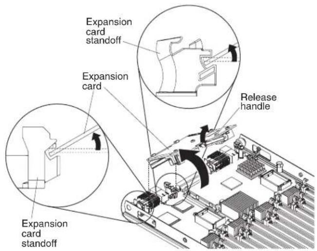
text_image
Expansion card standoff Expansion card Expansion card standoff Release handleInstallingasolidstatedrive
Usethisinformationtoinstallasolidstatedrive.
YoucaninstalluptotwosolidstatedrivesintheSSDexpansioncard.Theblade serversupportsusingRAID0orRAID1whentwostoragedrivesareinstalled. See UsingtheLSILogicConfigurationUtilityprogram"onpage82for informationaboutRAIDconfiguration.
Toinstallasolidstatedrive,completethefollowingsteps:
-
RemovetheSSDexpansioncard(see"RenovinganSSDexpansioncard" on page37forinstructions).
-
TurnovertheSSDexpansioncard.
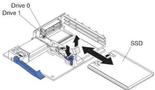
text_image
Drive 0 Drive 1 SSD-
Touchthestatic-protectivepackagethatcontainsthesolidstatedrivetoany unpainted metal surface on the BladeCenter unit or any unpainted metal surface onanyothergroundedrackcomponent;then,removethesolidstatedrivefrom thepackage.
-
Slidethesolidstatedriveintotheslotuntilitisfirmlyseatedintheconnector.
-
If you have a second solid stated rivetoinstall, repeat steps 3 and 4.
-
Closetheretentionleverandsecureitwiththebluetab.
Note: Youmighthavetopressthebluetabbeforeyouclosetheretentionlever.
- InstalltheSSDexpansioncard(see "InstallinganSSDexpansioncard" on page 37 for instructions).
Removingasolidstatedrive
Usethisinformationtoremoveasolidstatedrive.
Thebladeserverhasasolidstatedriveexpansioncardforinstallingorremoving solidstatedrives.Toremoveasolidstatedrive,completethefollowingsteps:
-
Before you begin, read "Safety" on page and "Installation guidelines" on page 23.
-
RemovetheSSDexpansioncard(see "RemovinganSSDexpansioncard" on page37 for instructions).
-
TurnovertheSSDexpansioncard.

text_image
Drive 0 Drive 1 SSD-
Pressdownonthebluetab. Theretentionleverautomaticallyopenssothatthe solidstatedriveordrivesareaccessible.
-
Slidethesolidstatedriveoutoftheslot.
Note: When you remove a drive from the SSD expansion card, consider labeling the driveto indicate the slot from which the drivewas removed so that you can install the drive back into the same slot.
- Closetheretentionleverandsecureitwiththebluetab.
Note: You might need top press the bluet ab before you close ther retention lever.
InstallingaDIMM-BladeCenterHX5
The bladeserverhasatotalof16directinlinememorymodule(DIMM)slots. The bladeserversupportsverylowprofile(VLP)DDR3DIMMswitherrorcode correction(ECC)in2GB,4GB,8GB,and16GBcapacities.
ForacurrentlistofsupportedDIMMsforthebladeserver,see http://www.ibm.com/servers/eserver/serverproven/compat/us/eserver.html.
DependingonthememorymodethatissetintheSetuputility,thebladeserver cansupportaminimumof4GBandamaximumof128GBofsystemmemoryon thesystemboardinabladeserverwithoneprocessor.Iftwomicroprocessorsare installed,thebladeservercansupportaminimumof8GBandamaximumof256 GBofsystemmemory.
MemorymustbeinstalledinpairsofDIMMsperprocessorinstalled.DIMMsmustbethesamesize,speed,andtechnologywithininstalledpairs.
Ifasingleprocessorisinstalled, itcanaccessthefirsteightDIMMslots. The followingtableliststhememoryconfigurationsandinstallationorderforthe BladeCenterHX5whenoneprocessorisinstalled.
Table6. Systemmemoryconfigurationforasingleprocessor(1microprocessor)
| Installed memory | DIMMsocket | |||||||
| 1 | 2 | 3 | 4 | 5 | 6 | 7 | 8 | |
| 2DIMMsXX | ||||||||
| 4DIMMsXXXX | ||||||||
| 6DIMMsX | X | X | X | X | X | |||
| 8DIMMsXXXX | XXXXX | |||||||
The following table lists the memory configurations and installation order for the BladeCenterHX5 when two processors are installed.
Table7.Systemmemoryconfigurationforatwoprocessors(2microprocessors)
| Installedmemory | DIMMsocket | |||||||||||||||
| 1 | 2 | 3 | 4 | 5 | 6 | 7 | 8 | 9 | 1 | 0 | 1 | 1 | 1 | 2 | 1 | |
| 2DIMMsXX | ||||||||||||||||
| 4DIMMsXXXX | ||||||||||||||||
| 6DIMMsXXXXXX | ||||||||||||||||
| 8DIMMsXXXXXXX | ||||||||||||||||
| 10 DIMMs | X | X | X | X | X | X | X | X | X | X | ||||||
| 12 DIMMs | X | X | X | X | X | X | X | X | X | X | X | X | ||||
| 14DIMMs | X | X | X | X | X | X | X | X | X | X | X | X | X | X | ||
| 16DIMMs | XXXX | XXXX | XXXX | XXXX | ||||||||||||
Important: If you are installing memory in a scalable blade complex, you should install the DIMMstohaveabalanceofmemoryamongprocessors. Additional memory can be installed in the top-most Blade Center HX5 of the scalable blade complex bladeservers that you donot need to disassemble the scalable blade complex. For example, if you are installing four DIMMs in a scalable blade complex consisting of two Blade Center HX5 bladeservers, you would install two DIMMs (in sockets 1 and 4) of each bladeserver.
Ifoneprocessorisinstalled, memorymirroringissetupasfollows:
Table8. Memorymirroringwithoneprocessor
| DIMMQuadrant | MirroredQuadrant | |
| DIMM1,DIMM2,DIMM3,DIMM4 | DIM | M5,DIMM6,DIMM7,DIMM8 |
Iftwoprocessorsareinstalled, memorymirroringissetupasfollows:
Table9. Memorymirroringwithtwoprocessors
| DIMMQuadrantMirroredQuadrant | |
| DIMM1, DIMM2, DIMM3, DIMM4DIMM5, DIMM6, DIMM7, DIMM8 | |
| DIMM9, DIMM10, DIMM11, DIMM12DIMM13, DIMM14, DIMM15, DIMM16 | |
TheBladeCenterHX5bladeserveralsosupportsmemorysparing, in which the content of the failing DIMM are transferred to the spare DIMM. To enable memory sparing, the DIMMs installed for each process must be identical.
Note: See "InstallingaDIMM-IBMMAX5" on page 33 form more information about memory requirements for the IBMMAX5 expansion blade.
Ifoneprocessorisinstalled, memorysparingissetupasfollows:
Table10. Memory sparing with one processor
| DIMMPairSparePair | |
| DIMM1,DIMM4DIMM2,DIMM3 | |
| DIMM5,DIMM8DIMM6,DIMM7 |
Iftwoprocessorsareinstalled, memorysparingissetupasfollows:
ToinstallaDIMM, completethefollowingsteps:
Table11. Memory sparing with twoprocessors
| DIMMPairSparePair | |
| DIMM1,DIMM4DIMM2,DIMM3 | |
| DIMM5,DIMM8DIMM6,DIMM7 | |
| DIMM9,DIMM12DIMM10,DIMM11 | |
| DIMM13,DIMM16DIMM14,DIMM15 |
ToinstallaDIMM, completethefollowingsteps:
- Before you begin, read "Safety" on page and "Installation guidelines" on page 23.
- LocatetheDIMMconnectors(see "Bladeserverconnectors-BladeCenterHX5" onpage21). DeterminetheDIMMconnectorintowhichyouwillbeinstalling memory.
- IfanothermemorymoduleisalreadyinstalledintheDIMMconnector,remove it(see"RemovingaDIMM-BladeCenterHX5" onpage42).
- Touch the static-protective package that contains the DIMM to any unpainted metalsurfaceontheBladeCenterunitoranyunpaintedmetalsurfaceonanyothergroundedrackcomponentintherackinwhichyouareinstallingtheDIMMforatleasttwoseconds;then,removetheDIMMfromitspackage.
- To install the DIMMs, repeat the following steps for each DIMM that you install:
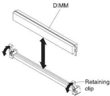
text_image
DIMM Retaining clipa. MakesurethatbothretainingclipsontheDIMMconnectorintowhichyou areinstallingtheDIMM,areintheopenposition.
b. TurntheDIMMsothattheDIMMkeysaligncorrectlywiththeDIMM connectoronthesystemboard.
Attention: To avoid breaking theretaining clipsordamaging the DIMM connectors, handle the clips gently.
c. PresstheDIMMintotheDIMMconnector. Theretainingclipswilllockthe DIMMintotheconnector.
d. Makesurethatthesmalltabsontheretainingclipsareinthenotcheson theDIMM.IfthereisagapbetweentheDIMMandtheretainingclips,the DIMMhasnotbeencorrectlyinstalled.PresstheDIMMfirmlyintothe connector,andthenpresstheretainingclipstowardtheDIMMuntilthe tabsarefullyseated.WhentheDIMMiscorrectlyinstalled,theretaining clipsareparalleltothesidesoftheDIMM.
RemovingaDIMM-BladeCenterHX5
Use this information to remove adual in line memory module (DIMM) from the bladeserver.
The following illustrations show show to remove a DIMM from the bladeserver.

text_image
DIMM Retaining clipToremoveaDIMM, completethefollowingsteps:
-
Before you begin, read "Safety" on page and "Installation guidelines" on page 23.
-
LocatetheDIMMconnectors(see"Bladeserverconnectors-BladeCenterHX5" onpage21).DeterminewhichDIMMyouwanttoremovefromtheblade server.
Attention: To avoid breaking the retaining clips or damaging the DIMM connectors, handle the clips gently.
-
MakesurethatbothretainingclipsonDIMMconnectorintowhichyouwillbe removingtheDIMMareintheopenposition.
-
Using your fingers, pull the DIMM out of the connector.
Installingahypervisorkey
Usetheseinstructionstoinstallahypervisorkeyinthebladeserver.
If you are using the Blade Center HX5 bladeserverin virtualized environment, you might need to install a hypervisor key, depending on the virtualization software that you are using. If you are using a scalable blade complex that is configured as a single hardware partition, install the hypervisor key in the bottom (left) bladeserverin the complex.
Ifthebladeserversinascalablebladecomplexareoperatingindependently,you mighthavetoinstallahypervisorkeyineachbladeserver.Todeterminewhether youneedahypervisorkey,seethedocumentationthatcomeswithyour virtualizationsoftware.Formoreinformationaboutvirtualization,see http://www.ibm.com/itsolutions/virtualization/.
Note:TheBladeCenterHX5supportstheoptionpartnumber41Y8278,which containsVMWareESXi4.0.Whenyouorderareplacement,order42D0545,which isablade2GBUSBkey.
The following illustrations show the installation of the hypervisor key.
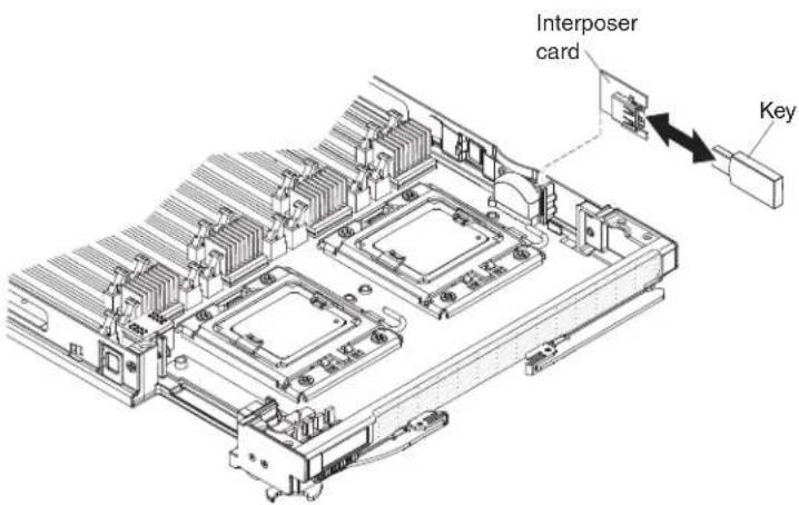
text_image
Interposer card KeyToinstallahypervisorkey,completethefollowingsteps:
-
Before you begin, read "Safety" on page and "Installation guidelines" on page 23.
-
Removetheaccesspanelifyouhavethestandardheatsinksinstalled.
Note: If you have the all heatsinks installed, you don't need to remove the access panel.
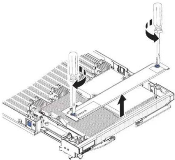
natural_image
Technical diagram of a mechanical assembly with two screwdrivers and directional arrows indicating motion (no text or symbols)a. Usingascrewdriveroracoin,turneachofthescrewstowardthemiddleof thebladeserveruntiltheyareintheunlockedposition.
b. Whileyouliftthebackoftheaccesspanel, slidethepanelawayfromthe bezel.
- Removethehypervisorinterposer:
a. Locatethehypervisorinterposeronthesystemboard(see"Major componentsofthebladeserver"onpage12).
b. Pressdownonthefrontedgeofthehypervisorinterposertodisengagethe hypervisorinterposerfromthehypervisorinterposercardguide.
c. Carefullyliftthehypervisorinterposerupfromthesystemboard.
-
Touchthestatic-protectivepackagethatcontainsthehypervisorkeytoany unpainted metal surface on the BladeCenter unit or any unpainted metal surface onanyothergroundedrackcomponentintherackinwhichyouareinstalling thehypervisorkeyforatleast2seconds;then,removetheUSBmodulefrom itspackage.
-
Install the hypervisor key into the hypervisor adapter:
a. Orienttheconnectoronthehypervisorkeywiththeconnectoronthehypervisoradapter.
b. Useyourfingerstopushthehypervisorkeyintothehypervisoradapter.
- Installthehypervisoradapter:
a. Orienttheconnectoronthehypervisorinterposerwiththeinterposer connectoronthesystemboard, aligningthepinsonthesideofthe hypervisorinterposerwiththepinholesontheinterposerconnector(see "Bladeserverconnectors-BladeCenterHX5" onpage21).
b. Useyourfingerstopushtheadapterintothecnjectoronthebladeserver. Attention: Becarefulnottodamagethepinsonthehypervisorinterposer.
- Installtheaccesspanelifyouhavestandardheatsinksinstalled.
Note: If you have the all heatsinks installed, you don't need to install the access panel.
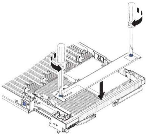
natural_image
Technical line drawing of a mechanical assembly with two vertical sensors and a central platform (no text or symbols)a. Makesurethatthescrewsontheaccesspanelareintheopenposition(the screwinsertisparalleltothesideoftheaccesspanel).
b. Slidethebackofthecoverunderthebladeserverbezel, aligningthescrews withtheslotsonthebladeserver.
c. Using as crew driver or acoin, turn each of the screws away from the middle of the blades server until it is in the locked position.
Removingahypervisorkey
Usethisinformationtoremoveahypervisorkeyfromthebladeserver.
The following illustrations show stheremovalofahypervisorkey from the blade server.
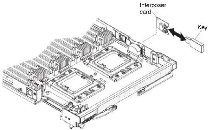
text_image
Interposer card KeyToremovethehypervisorkey, completethefollowingsteps:
-
Before you begin, read "Safety" on page and "Installation guidelines" on page23.
-
Removetheaccesspanelifyouhavethestandardheatsinksinstalled.
Note: If you have the all heatsinks installed, you don't need to remove the access panel.

natural_image
Technical line drawing of a mechanical assembly with two screwdrivers and a conveyor belt (no text or symbols)a. Usingascrewdriveroracoin,turneachofthescrewstowardthemiddleof thebladeserveruntiltheyareintheunlockedposition.
b. While you lift the back of the access panel, slid the panel away from the bezel.
-
Locatethehypervisorinterposeronthesystemboard(see "Majorcomponents ofthebladeserver" onpage12).
-
Pressdownonthefrontedgeofthehypervisorinterposertodisengagethe hypervisorinterposerfromthehypervisorinterposercardguide.
-
Carefullyliftthehypervisorinterposerupfromthesystemboard.
-
Pullthehypervisorkeyawayfromthehypervisorinterposer.
Installinganl/Oexpansioncard
The following sections describe how to install the following expansion cards:
•CFFhexansioncards,forexample:
-OLogic2-Port10GbConvergedNetworkAdapter
-OLogicEthernetand8GBFibreChannelExpansionCard
-2/4-PortGbEthernetExpansionCard
-2-Port40GbInfinibandExpansionCard
-Brocade2-Port10GbEthernetConvergedNetworkAdapter
-Broadcom4-Port10GbEthernetExpansionCard
-Broadcom2-Port10GbEthernetExpansionCard(CFFh)
-EmulexVirtualFabricAdapter
-EmulexVirtualFabricAdapterAdvanced
-Intel10Gb2-PortEthernetExpansionCard
•CIOvexpansioncards,forexample:
-EthernetExpansionCard
- QLogic8GbFibreChannelExpansionCard
-QLogic4GbFibreChannelExpansionCard
-SASConnectivityCard
Note: ACIOvexpansioncardissupportedforallcombinations.
The following illustrations show sthe cardsthataresupportedinabladeserver.
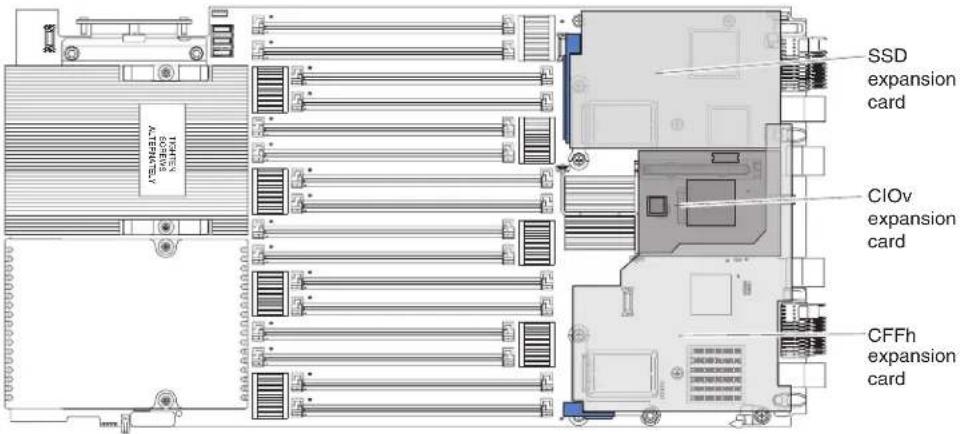
text_image
SSD expansion card CIOv expansion card CFFh expansion cardForinformationaboutinstallinganSSDexpansioncard,see"InstallinganSSD expansioncard"onpage37.
TodeterminewhichexpansioncardsaresupportedintheBladeCenterHX5blade server,seehhttp://www.ibm.com/servers/eserver/serverproven/compat/us/eserver.htm].
Productdocumentationforexpansioncardsisavailableaathttp://publib.boulder.ibm.com/infocenter/bladectr/documentation/index.jsp?topic=/com.ibm.bladecenter.common.nav.doc/bc_expansion_cards_welcome_page.html
InstallingaCIOvexpansioncard
UsetheseinstructionstoinstallaCIOvexpansioncardinthebladeserver.
The following illustrations show the location and installation of a CIO expansion card.
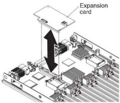
text_image
Expansion cardToinstallaCIOvexpansioncard,completethefollowingsteps:
-
Before you begin, read "Safety" on page and "Installation guidelines" on page23.
-
IfaCFFhexpansioncardisinstalled,removeit(see"RemovingaCFFhexpansioncard"onpage49forinstructions).
-
LocatetheCIOvexpansionconnector(see"Bladeserverconnectors-BladeCenterHX5" onpage21).
-
Touchthestatic-protectivepackagethatcontainstheexpansioncardtoany unpainted metal surface on the BladeCenter unit or any unpainted metal surface onanyothergroundedrackcomponent;then,removethexpansioncardfrom thepackage.
-
OrienttheconnectorontheexpansioncardwiththeCIOvexpansionconnector onthesystemboard;then,pressthecardintotheCIOvexpansionconnector.
-
Firmlypressontheindicatedlocationstoseattheexpansioncard.
Note: For device-driver and configuration information to complete the installation of the expansion card, seethedocumentation that comes with the expansion card.
- InstalltheCFFhexansioncard, if you removed one from the bladeserver (see "InstallingaCFFhexansioncard" for instructions).
InstallingaCFFhexpansioncard
Usetheseinstructionstoinstallacompact-form-factorexpansioncardintheblade server.
The bladeserversupportsahorizontal-combination-form-factor(CFFh)expansion card. The following illustrations show show to install a CFFhexpansion card.
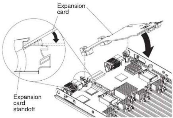
text_image
Expansion card Expansion card standoffToinstallaCFFhexansioncard,completethefollowingsteps:
-
Before you begin, read "Safety" on page and "Installation guidelines" on page23.
-
Locatethebladeserverexpansionconnector(see "Bladeserverconnectors-BladeCenterHX5" onpage21).
-
Ifacoverisinstalledonthebladeexpansionconnector,removeitbyusing yourfingerstoliftthecoverfromthebladeexpansionconnector.
-
Touchthestatic-protectivepackagethatcontainstheexpansioncardtoany unpainted metal surface on the BladeCenter unit or any unpainted metal surface onanyothergroundedrackcomponent;then,removethexpansioncardfrom thepackage.
-
Orienttheexpansioncardandslidetheslotsatthebackofthecardontothe pinsontheexpansion-cardstandoff;then,gentlypivotthecardintotheblade serverexpansionconnector.
-
Firmlypressontheindicatedlocationstoseattheexpansioncard.
Note: For device-driver and configuration information to complete the installation of the expansion card, seethedocumentation that comes with the expansion card.
Removinganl/Oexpansioncard
The following sections describe how to remove the following expansion cards:
•CFFh
•CIOv
ForinformationaboutremovinganSSDexpansioncard,see"RemovinganSSD expansioncard"onpage37.
RemovingaCFFhexansioncard
UsetheseinstructionstoremoveaCFFhexansioncardfromthebladeserver.
ToremoveaCFFhexansioncard, completethefollowingsteps:
-
Before you begin, read "Safety" on page and "Installation guidelines" on page23.
-
LocatetheCFFhexansioncard.TheCFFhcardisinstalledintheblade expansionconnector(see"Bladeserverconnectors-BladeCenterHX5"onpage [2]).
-
UseyourfingerstoholdtheedgeoftheCFFhexpansioncardwhereit connectstothebladeexpansionconnector;then,liftuponthecard.

text_image
Expansion card Expansion card standoff Release lever- Liftthecardawayfromtheexpansion-cardstandoff.
RemovingaCIOvexpansioncard
UsetheseinstructionstoremoveaCIOvexpansioncardfromthebladeserver.
The following illustrations show to remove a vertical-combination-I/O(CIOv) expansion card.
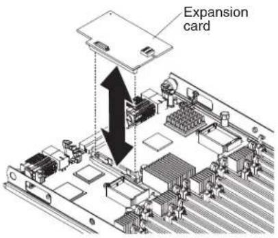
text_image
Expansion cardToremoveaCIOvexpansioncard,completethefollowingsteps:
- Before you begin, read "Safety" on page and "Installation guidelines" on page23.
- RemovetheCFFhexpansioncard,ifoneisinstalled(see"RemovingaCFFh expansioncard"onpage49forinstructions).
- LocatetheCIOvexpansionconnector(see"Bladeserverconnectors-BladeCenterHX5"onpage21).
- Using your fingers, mov ether retaining clips away from the CIOvcard; then, lift the card out of the connector.
Installingamicroprocessorandheatsink
Usethisinformationtoinstallamicroprocessorandheatsinkinthebladeserver.
Note: The optional microprocessor that IBM supports are limited by the capacity and capability of the server. Anymicroprocessor that you install must have the same specifications asthemicroprocessor that came with the bladeserver.
The following illustrations show to install a microprocessor and heatsink in the bladeserver.
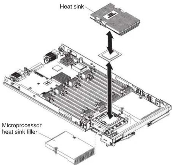
text_image
Heat sink Microprocessor heat sink fillerAttention:
-
Donotuscanytoolsorsharpobjectstoliftthelockingleveronthe microprocessorsocket.Doingsomightresultinpermanentdamagetothe systemboard.
-
Donottouchthecontactsinthemicroprocessorsocket.Touchingthesecontacts mightresultinpermanentdamagetothesystemboard.
Toinstallamicroprocessorandheatsink,completethefollowingsteps:
-
Before you begin, read "Safety" on page and "Installation guidelines" on page 23.
-
Carefully lay the bladeserverona flat, static-protectives surface.
-
Removetheaccesspanelifyouareinstallingstandardheatsinks.
Note: If you installing tall heatsinks, you donotneed to remove the access panel.
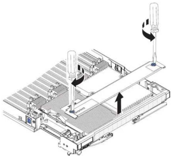
natural_image
Technical line drawing of a mechanical assembly with two screwdrivers and a conveyor belt (no text or symbols)a. Usingascrewdriveroracoin,turneachofthescrewstowardthemiddle ofthebladeserveruntiltheyareintheunlockedposition.
b. While you lift the back of the access panel, slid the panel away from the bezel.
- Removetheaccesspanelifyouhavethestandardheatsinksinstalled.
Note: If you have the all heats inks installed, you don't need to remove the access panel.
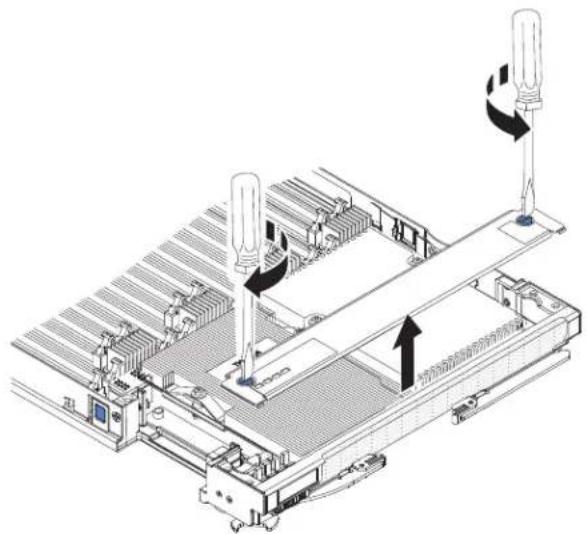
natural_image
Technical diagram of a mechanical assembly with two vertical sensors and directional arrows indicating motion (no text or symbols present)a. Usingascrewdriveroracoin,turneachofthescrewstowardthemiddle ofthebladeserveruntiltheyareintheunlockedposition.
b. Whileyouliftthebackoftheaccesspanel, slidethepanelawayfromthe bezel.
- Openthemicroprocessorsocketreleaseleverandretainer.

text_image
Microprocessor release lever Microprocessor retainera. Rotatethereleaseleveronthemicroprocessorsocketfromitsclosedand lockedpositionuntilitstopsinthefullyopenposition(approximately a 135°angle).
b. Rotatethemicroprocessorretaineronthemicroprocessorsocketfromits closedpositionuntilstopsinthefullyopenposition(approximately a 135°angle).
-
Ifadustcoverisinstalledoverthemicroprocessorsocket,liftthedustcover fromthesocketandstoreitinasafeplace.
-
Installthemicroprocessorinthemicroprocessorinstallationtool.
Attention: If you are installing E7 series microprocessors in the bladeserver, you must set them microprocessor installation tool with the text "X7500+E7" on the bottom of the tool (seeth following illustration). Tool that donot havethistext on the bottom will not work correctly with the E7 series microprocessors.
text_image
X7500 + E7a. Removethestatic-protectivebagandthefoamsurroundingthebagfrom thebox.
b. Touchthestatic-protectivebagthatcontainsthenewmicroprocessorto any unpainted surface on the BladeCenter chassis or any unpainted metal surfaceonanyothergroundedrackcomponent.
c. Carefullyremovethemicroprocessorfromthestatic-protectivebag, touchingonlytheedgesofthemicroprocessor.
d. If thereisaplasticprotectivecoveronthebottomofthemicroprocessor, carefullyremoveit.
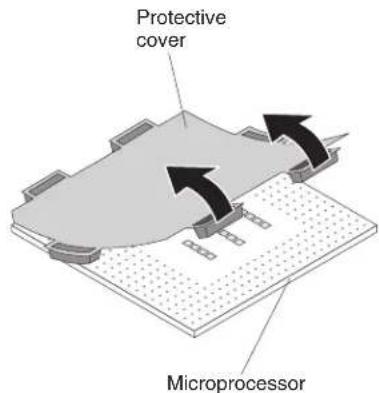
text_image
Protective cover Microprocessore. Putthemicroprocessorbackinthebox,componentsidedown,onthe solidpieceoffoam.
f. Twist the handle of the installation tool counterclock wises that it is in the open position.
g. Using the triangle on the microprocess to align with the installation tool, placethemicroprocessor on the underside of the tool.
h. Twistthehandleoftheinstallationtoolclockwisetosecurethe microprocessorinthetool.
Note: You can pickup or release them microprocessor by twisting the microprocessor installation tool handle.
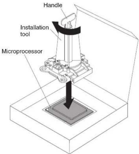
text_image
Handle Installation tool Microprocessor- Carefully placethemicroprocessor into the microprocessor socket, using the alignment tabson the microprocessor with the alignment notches in the microprocessor socket as a guide.
Thealignmentholesonthetoolwillnotsitflushonthemicroprocessor bracketscrews. However, the holescanbeusedasaguidetoensure the properalignmentbetweenthemicroprocessorinstallationtoolandthe microprocessorbracket.
Attention:
- Donotpressthemicroprocessorintothesocket.
- Donottouchexposedpinsofthemicroprocessorsocket.
- Makesurethatthemicroprocessorisorientedandalignedcorrectlyinthe socketbeforeyoutrytoclosethemicroprocessorretainer.
- Donottouchthethermalmaterialonthebottomoftheheatsinkorontop ofthemicroprocessor.Touchingthethermalmaterialwillcontaminateit.If thethermalmaterialonthemicroprocessororheatsinkbecomes contaminated,contactyourservicetechnician.
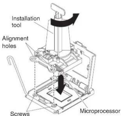
text_image
Installation tool Alignment holes Screws Microprocessor- Carefullyclosethemicroprocessorretainer.
-
Rotatethelockingleveronthemicroprocessorsockettotheclosedandlocked position.Makesurethattheleverissecuredinthelockedpositionbypassing thetabonthemicroprocessorsocket.
-
If you are installing a heatsink that was removed from the bladeserver, complet the following steps:
Attention:
- Donottouchthethermalmaterialonthebottomoftheheatsink.Touching thethermalmaterialwillcontaminateit.Ifthethermalmaterialonthe microprocessororheatsinkbecomescontaminated,contactyourservice technician.
- Donottouchexposedpinsofthemicroprocessorsocket.
a. Makesurethatthethermalmaterialisstillonthebottomoftheheatsink andonthetopofthemicroprocessor.
b. Alignandplacetheheatsinkontopofthemicroprocessorintheretention bracket, thermalmaterialsidedown. Pressfirmlyontheheatsink.
c. Alignthethreescrewsontheheatsinkwiththeholesontheheat-sink retentionmodule.
d. Pressfirmlyonthecaptivescrewsandtightenthemwithascrewdriver, alternatingamongthescrewsuntiltheyaretight.Ifpossible,eachscrew shouldberotatedtwofullrotationsatatime.Repeatuntilthescrewsare tight.Donotovertightenthescrewsbyusingexcessiveforce.Ifyouare usingatorquewrench,tightenthescrewsto8.5Newton-meters(Nm)to 13Nm(6.3foot-poundsto9.6foot-pounds).
- If you are installing an new wheatsink, complete the following steps:
Attention:
- Donotsetdowntheheatsinkafteryouremovetheplasticcover.
- Donottouchthethermalmaterialonthebottomoftheheatsink.Touching thethermalmaterialwillcontaminateit.Ifthethermalmaterialonthe microprocessororheatsinkbecomescontaminated,contactyourservice technician.
- Donottouchexposedpinsofthemicroprocessorsocket.
a. Removetheplasticprotectivecoverfromthebottomoftheheatsink.
b. Alignandplacetheheatsinkontopofthemicroprocessorintheretention bracket, thermalmaterialsidedown. Pressfirmlyontheheatsink.
c. Alignthescrewsontheheatsinkwiththeholesontheheat-sinkretention module.
d. Pressfirmlyonthecaptivescrewsandtightenthemwithascrewdriver, alternatingamongthescrewsuntiltheyaretight.Ifpossible,eachscrew shouldberotatedtwofullrotationsatatime.Repeatuntilthescrewsare tight.Donotovertightenthescrewsbyusingexcessiveforce.Ifyouare usingatorquewrench,tightenthescrewsto1.13±0.13Newton-meters (Nm)(10±0.15in-lbs).
-
Makesurethat, ataminimum, memorymodules are installed in DIMM connectors and 4. See "InstallingaDIMM-BladeCenterHX5" on page 39 formoreinformationoninstallingamemorymodule.
-
Installtheaccesspanelifyouremoveditearlier.
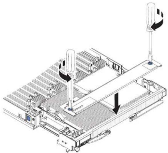
natural_image
Technical line drawing of a mechanical assembly with two vertical posts and a central conveyor (no text or symbols)a. Makesurethatthescrewsontheaccesspanelareintheopenposition(the screwinsertisparalleltothesideoftheaccesspanel).
b. Slidethebackofthecoverunderthebladeserverbezel, aligningthe screwswiththeslotsonthebladeserver.
c. Using as crew driver or acoin, turn each of the screws away from the middle of the blades server until it is in the locked position.
Installingthe1-nodespeedburstcard
Usethisinformationtoinstalla1-nodespeedburstcardinabladeserver.
Toinstalla1-nodespeedburstcard, completethefollowingsteps:

text_image
Alignment pins-
Before you begin, read "Safety" on page and "Installation guidelines" on page 23.
-
Standthebladeserveruprightonaclean,flatworksurface,withthescalability fillerconnectorfacingup.
-
Openthelowerhandle(rotatethelowerhandlesdown)toallowtheblade servertositflatontheworksurface.
-
Removethescalabilityfillerfromthebladeserveror2-nodescalabilitycard (see 'Installingthe2-nodescalabilitycard" onpage60).Toremovethe scalabilityfiller,completethefollowingsteps:
a. Usingthe3/16"hexdriverthatisprovidedwiththe1-nodespeedburst card,loosenthenutthatattachesthefillertothebladeserver.
b. Liftthefilleroffthebladeserver.
-
Alignthepinsonthebottomofthe1-nodespeedburstcardwiththeholeson thescalabilityconnectoronthebladeserver.
-
Pressdownfirmlysothatthe1-nodespeedburstcardisflushwith the scalabilityconnectoronthebladeserver.
-
Tightenthescrewonthefillerbyhandtoensurethatthescrewthreadsstart properly.
Important: Alwayshandtightenthescrewbeforeusingthe3/16"hexdriver.
- Usingthe3/16"hexdriver,tightenthenutthatattachesthe1-nodespeedburst cardtothebladeserver.
Note: If you are using a torquedriver, the correct torque is 15 in-lb.
Removingthe1-nodespeedburstcard
Usethisinformationtoremovethe1-nodespeedburstcardfromabladeserver.
Toremovethe1-nodespeedburstcard,completethefollowingsteps.
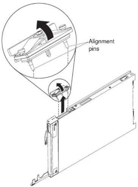
text_image
Alignment pins- Before you begin, read "Safety" on page and "Installation guidelines" on page 23.
- Standthebladeserveruprightonaclean,flatworksurface,withthescalability connectorfacingup.
- Openthelowerhandle(rotatethelowerhandlesdown)toallowtheblade servertositflatontheworksurface.
- Usingthe3/16"hexdriverthatcomeswiththe1-nodespeedburstcard,loosen thenutthatattachesthe1-nodespeedburstcardtothebladeserver.
- Liftthe1-nodespeedburstcardoffthebladeserver.
Completingtheinstallation
Tocompletetheinstallation,completethefollowingtasks.
- Assemblethescalablebladecomplexifnecessary(see "Assemblingascalable bladecomplex").
- InstalltheIBMMAX5expansionbladeifnecessary(see "Install"nganIBM MAX5"onpage62).
- Closethebladeservercover(see "Installingthebladeservercover" on page 67).
Statement21


CAUTION:
Hazardousenergyispresentwhenthebladeserverisconnectedtothepower source.Alwaysreplacethebladeservercoverbeforeinstallingtheblade server.
- ReinstallthebladeserverintotheBladeCenterchassis(see "InstallngabladeserverinaBladeCenterchassis" onpage68).
- Turnonthebladeserver(see "Turningonthebladeserver" onpage15). If you have just connected the power cord of the Blade Center chassistoelectrical outlets, you must wait until the power LED onthe bladeserver flashesslowly before you press the power button.
- For certain optional devices, you might have to run the blades server setup utility to configure the blades server (see Chapter 4, "Configuring the blade server," on page 71). Seethedocumentation that comes with your optional device for additional information.
Assemblingascalablebladecomplex
Use this information to assemble a scalable blade complex.
Toassembleascalablebladecomplex, you will need the following parts:
•TwoBladeCenterHX5bladeservers
- 2-nodescalabilitykit, which include the 2-nodescalability card, the scalability tray, and the 3/16"hexdriver.
Toassembleascalablebladecomplex, completethefollowingsteps.
Note: Makesurethatyouinstalledahypervisorkeyintheprimarybladeserver, if required, tousethescalablebladecomplexasasinglehardwarepartitionina virtualizedenvironment. Todeterminewhetheryouneedtoinstallahypervisor
key,seethedocumentationthatcomeswithyourvirtualizationsoftware.Formore informationaboutvirtualization,seehttp://www.ibm.com/itsolutions/virtualization/.
- Before you begin, read "Safety" on page and "Installation guidelines" on page23.
- Installthescalabilitytrayinthetopmostbladeserver(see"Installingthe scalabilitytray"forinstructions).
- Attachthebladeserverwiththescalabilitytraytothebottombladeserver.

text_image
Cover Pins Blade server cover release Blade server cover releasea. Lowerthetopmostbladeserversothattheslotsattherearslidedownonto thepinsattherearofthebottombladeserver,asshownintheillustration.
b. Pivotthetopmostbladeservertotheclosedposition,asshowninthe illustration,untilclicksintoplace.
- Installthe2-nodescalabilitycard(see "Installingthe2-nodescalabilitycard" on page60).
Installingthescalabilitytray
Usethisinformationtoinstallthescalabilitytrayonabladeserver.
Toinstallthescalabilitytray,completethefollowingsteps:
- Before you begin, read "Safety" on page and "Installation guidelines" on page23.
- Carefully lay the blades server on a flat, static-protective surface, with the cover sidedown.
- Alignthescalability tray flush with the bladeserver in the start position. The pinsonthescalability tray should be aligned with the holes in the bladeserver.
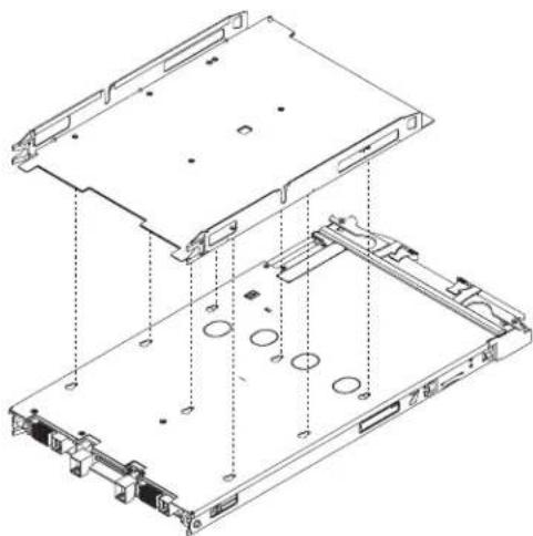
natural_image
Technical line drawing of an open computer drive chassis showing internal components and mounting holes (no text or labels)- Pressingdownfirmlyonthemiddleofthetray, slidethescalabilitytray forwardtowardthebezeluntilthereisanaudibleclickeachsideoftheblade server.

natural_image
Technical line drawing of a computer drive chassis with two directional arrows indicating movement or force (no text or symbols present)-
Attempttopullthescalability trayback to ensure that the scalability tray is firmly seated.
-
Lookintheholesoneachsideofthebladeservertoensurethatthespring platesareengaged.
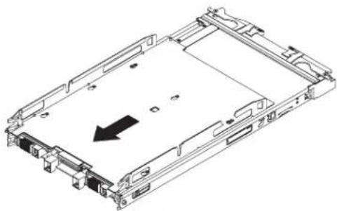
natural_image
Technical line drawing of a computer chassis with an arrow indicating a component (no text or symbols present)Installingthe2-nodescalabilitycard
Usethisinformationtoinstallthe2-nodescalabilitycardonabladeserver.
Toinstallthe2-nodescalabilitycard,completethefollowingsteps:
-
Before you begin, read "Safety" on page and "Installation guidelines" on page23.
-
Standthebladeserversuprightonaclean,flatworksurface,withthe scalabilityconnectoronthebladeserversfacingup.
-
Releasethelowerhandles(rotatethelowerhandlesdown)toallowtheblade serverstositflatontheworksurface.
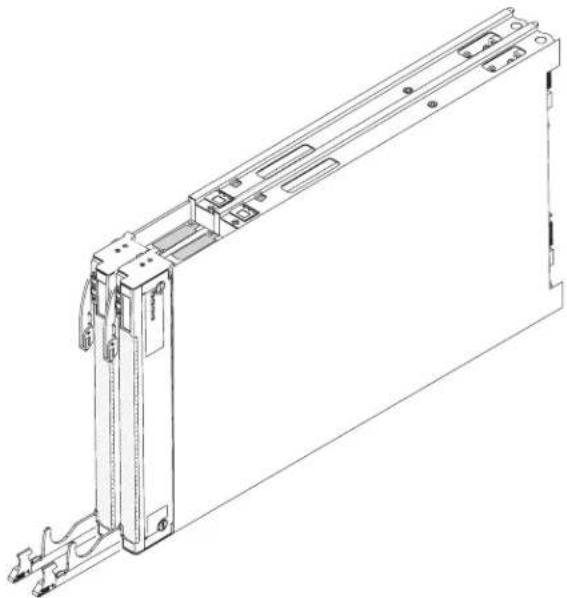
natural_image
Technical line drawing of a mechanical device with mounting brackets and internal components (no text or symbols)-
AlignthepinsonthebottomoftheIBM2-nodescalabilitycardwiththeholes onthescalabilityconnectoronthebladeserver.
-
Pressdownfirmlysothatthe2-nodescalabilitycardisflushwiththe scalabilityconnectoronthebladeserver.
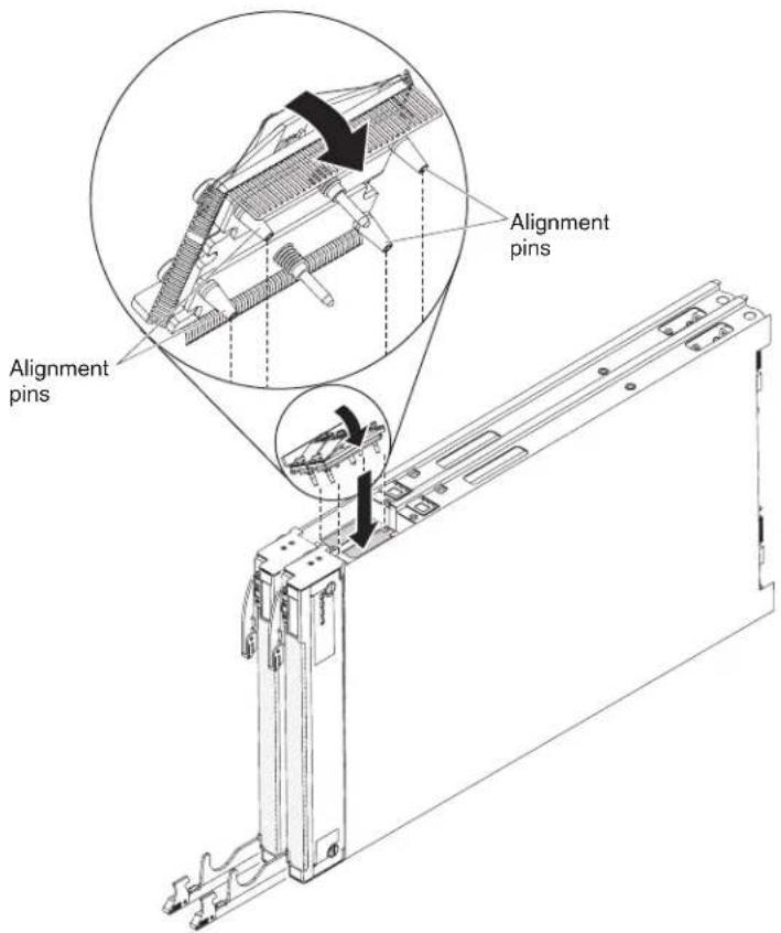
text_image
Alignment pins Alignment pins- Makesurethatthe2-nodescalabilitycardisflushwiththeedgeoftheblade server.
- Alternatelytightenthescrewsonthe2-nodescalabilitycardbyhandtoensure thatthescrewthreadsstartproperly.
Important: Alwayshandtighteneachscrewbeforeyouusethe3/16"hex driver.
- Alternatelytighteneachscrewonthe2-nodescalabilitycardusingthe3/16" hexdriver.Alternatethetighteningofeachscrewuntilbothscrewsare tightened.
Note: If you are using a torquedriver, the correct torque is 15 in-lb.
InstallinganIBMMAX5
UsetheseinstructionstoinstallanIBMMAX5.
Note: Before installing the IBM MAX5 expansion blade, makes sure that you have updated the firmware on the Blade Center HX5 bladeserver to the latest level. If you attach and try to set the IBM MAX5 expansion bladewithout updating the server firmware, you might get unexpected system behavior or the server might not power on. For information about updating the firmware on the Blade Center HX5 bladeserver, see "Updating firmware and device drivers" on page 82.
TherearetwoversionsoftheIBMMAX5expansionblade,referredtoastheIBM MAX5version1andIBMMAX5version2inthisdocument.IBMMAX5version2 hasa"MAX5"identifyinglabelonthebottomofthefrontbezel.Thefunctionality ofthetwoIBMMAX5expansionbladesareequivalentexceptforthetypeof DIMMssupported.ThetypeofDIMMssupportedwilldiffer,dependingonthe versionofIBMMAX5expansionbladeinstalled.ForthelistofDIMMsavailable foryourIBMMAX5expansionblade,seetheProblemDeterminationandService Guideorgotohttp://www.ibm.com/systems/support/foranupdatedparts listing.
ToinstallanIBMMAX5expansionblade,completethefollowingsteps.

text_image
IBM MAX5 Blade server cover release Upper ridge Power jumper Blade server cover release-
Before you begin, read "Safety" on page and "Installation guidelines" on page 23.
-
RemovethecoverontheBladeCenterHX5bladeserverifoneisinstalled(see "Removingthebladeservercover" onpage25forinstructions).
-
LocatethepowersharingconnectorontheBladeCenterHX5bladeserverand removethepowersharingcoverifoneisinstalled(see "Bladeserver connectors-BladeCenterHX5" onpage21).
-
TherearetwotypesofaccesspanelsavailableontheBladeCenterHX5blade server,dependingonwhetherallheatsinksareinstalledinthebladeserver. CompletethefollowingstepsifyouareinstallinganIBMMAX5expansion bladeonaBladeCenterHX5bladeserverthathastallheatsinks:
a. Removetheoperatorcontrolpanelaccesspanel:
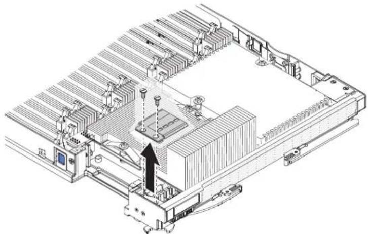
natural_image
Technical line drawing of an electronic device chassis with cooling fans and heat exchangers (no text or symbols)1) Using as crew driver, remove each of the crew son theright access panel.
2) Lifttheaccesspanelawayfromthebladeserver.
b. Removetheembeddedhypervisorcardaccesspanel:
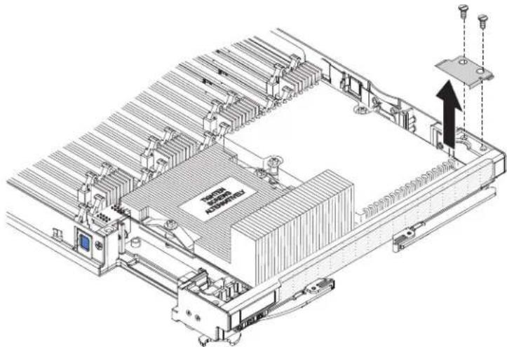
natural_image
Isometric technical diagram of an electronic device with labeled components and a directional arrow (no readable text or symbols)1) Using as crew driver, remove each of the screws on the right access panel.
2) Lifttheaccesspanelawayfromthebladeserver.
c. InstalltheEMCgasketontheupperridgeoftheBladeCenterHX5blade serverbezel.
d. Installtheoperatorcontrolpanelaccesspanel:

natural_image
Technical line drawing of an electronic device chassis with cooling fans and a black arrow indicating a component (no text or symbols present)1) Aligntheholesintheaccesspanelwiththeholesinthebladeserver.
2) Useascrewdrivertoinstallthescrewsintheholesoftheaccesspanel.
e. Installtheembeddedhypervisorkeyaccesspanel:
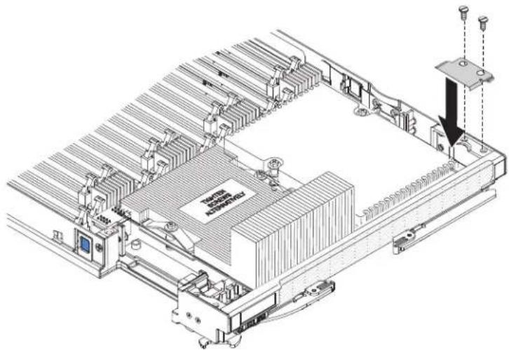
natural_image
Isometric technical diagram of a computer motherboard with cooling fans and drive slots (no text or symbols)1) Aligntheholesintheaccesspanelwiththeholesinthebladeserver.
2) Useascrewdrivertoinstallthescrewsintheholesoftheaccesspanel.
f. RemovetheheatsinkaccessplatesontheIBMMAX5expansionblade.
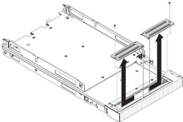
natural_image
Technical line drawing of a computer chassis with two vertical connectors and mounting holes (no text or symbols)1) LaytheIBMMAX5expansionbladeonaflat,static-protectivesurface, coversidedown.
2) Useascrewdrivertoremovebothheatsinkaccessplates.
-
Touchthestatic-protectivepackagethatcontainstheIBMMAX5toany unpainted metal surface on the BladeCenter unit or any unpainted metal surface onanyothergroundedrackcomponent;then,removetheoptionalexpansion unitfromthepackage.
-
OrienttheIBMMAX5asshownintheillustration.
-
LowertheIBMMAX5sothattheslotsattherearslidedownontothecover pinsattherearofthebladeserver;then,pivottheIBMMAX5downontothe bladeserver.
-
PresstheIBMMAX5firmlyintotheclosedpositionuntilitclicksintoplace.
-
InstalltheIBMMAX51-nodescalabilitycard(see "InstallingtheIBMMAX51-nodeScalabilitycard" onpage66forinstructions).
InstallingtheIBMMAX51-nodeScalabilitycard
UsethisinformationtoinstalltheIBMMAX51-nodescalabilitycardonablade server.
ToinstalltheIBMMAX51-nodescalabilitycard,completethefollowingsteps.
-
Before you begin, read "Safety" on page and "Installation guidelines" on page23.
-
Removethe1-nodeSpeedBurstcard(see "Installingthe1-nodespeedburst card" onpage56) orscalabilityfillerfromthebladeserver,dependingon which you have installed. Toremovethescalabilityfiller,completethe following steps:
a. Usingthesocketnutdriverprovidedwiththescalabilitykit,loosenthe nutthatattachesthefillertothebladeserver.
b. Liftthefilleroffofthebladeserver.
-
InstalltheIBMMAX5expansionblade(see "InstalinganIBMMAX5" on page62).
-
Removethecoverfortheexpansionblade(see"Removingthebladeserver cover"onpage25forinstructions).
-
Standthebladeserverandexpansionbladeuprightonaclean,flatwork surface,withthescalabilityconnectoronthebladeserversfacingup.
-
Openthelowerhandles(rotatethelowerhandlesdown)toallowtheblade serverandexpansionbladetositflatontheworksurface.
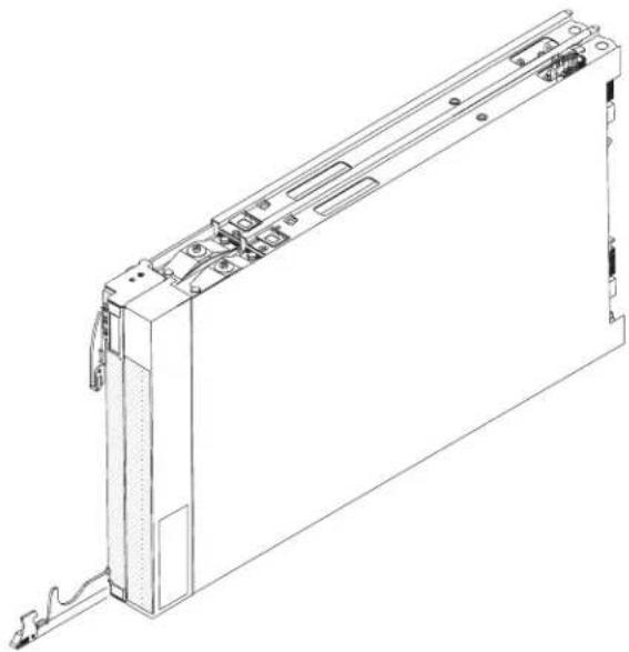
natural_image
Technical line drawing of a mechanical or electronic device component (no text or symbols visible)-
AlignthepinsonthebottomoftheIBMMAX51-nodescalabilitycardwith theholesonthescalabilityconnectoronthebladeserver.
-
Pressdownfirmlysothatthe1-nodescalabilitycardisflushwiththe scalabilityconnectoronthebladeserver.
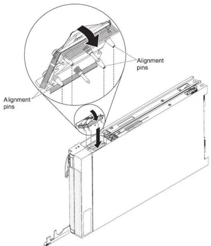
text_image
Alignment pins Alignment pins-
Makesurethatthe1-nodescalabilitycardisflushwiththeedgeoftheblade server.
-
Alternatelytightenthescrewsonthe1-nodescalabilitycardbyhandto ensurethatthescrewthreadsstartproperly.
Important: Always hand tight enough screw before you use the 3/16"hex driver.
Installingthebladeservercover
Usetheseinstructionstoinstallandclosethecoverforabladeserverorforthe topmostbladeserverinascalablebladecomplex.
Attention: You cannot insert the blades server into the Blade Center chassis until the cover is installed and closed. Donot attempt to overridethis protection.
Statement21

CAUTION:
Hazardousenergyispresentwhenthebladeserverisconnectedtothepower source.Alwaysreplacethebladecoverbeforeinstallingthebladeserver.
Toinstallandclosethebladeservercover,completethefollowingsteps:
- Before you begin, read "Safety" on page and "Installation guidelines" on page 23.
- Carefully lay the bladeserverona flat, static-protectives surface, orienting the bladeserver with the bezelpointing toward you.
- Lowerthecoversothattheslotsattherearslidedownontothepinsatthe rearofthebladeserver,asshownintheillustration.Beforeyouclosethecover, makesurethatallcomponentsareinstalledandseatedcorrectlyandthatyou havenotleftloosetoolsorpartsinsidethebladeserver.
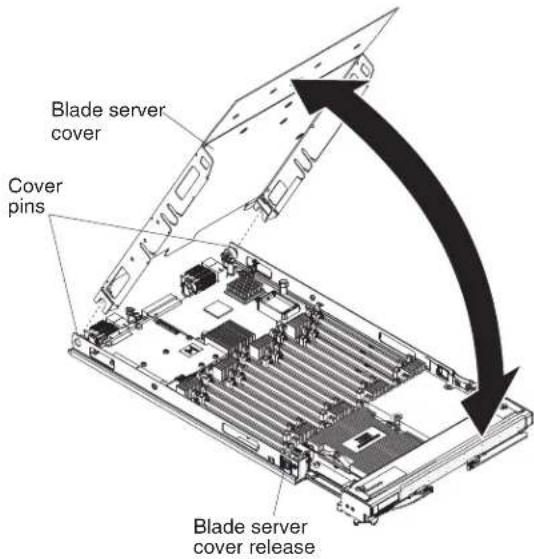
text_image
Blade server cover Cover pins Blade server cover release- Pivotthecovertotheclosedposition,asshownintheillustration,untilitclicks intoplace.
InstallingabladeserverinaBladeCenterchassis
UsetheseinstructionstoinstallaBladeCenterHX5bladeserverinaBladeCenter chassis.
The following illustrations show show to install a BladeCenterHX5 bladeserver into a BladeCenterchassis. Seethedocumentation for your BladeCenterchassis for additional information.
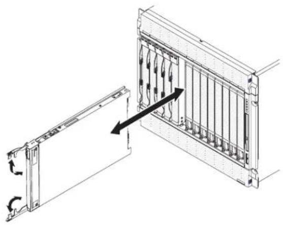
natural_image
Technical line drawing of a server rack with internal components and directional arrows indicating assembly (no text or symbols)Statement21

CAUTION:
Hazardousenergyispresentwhenthebladeserverisconnectedtothepower source.Alwaysreplacethebladecoverbeforeinstallingthebladeserver.
ToinstallaBladeCenterHX5bladeserver,completethefollowingsteps.
-
Before you begin, read "Safety" on page and "Installation guidelines" on page 23.
-
Selectthebladeserverbayforthebladeserver;atleastonebladeserverbayis required.
Notes:
a. ForBladeCenterchassisthatsupportupto14bladeservers,whenany bladeserverordeviceisinbladeserverbay7through14,powermodules mustbeinstalledinallfourpower-modulebays.Foradditional information,seetheInstallationandUser'sGuideforyourchassis.
b. If you are installing bladeserver that you removed, you must install it in the same bladeserver bay from which you removed. Some blade server configuration information and update options are established according to bladeserver bay number. Re installing bladeserver into a different bladeserver bay from the one it was removed from can have unintended consequences. If you install the bladeserver into a different bay, you might need to configure the bladeserver.
c. Tomaintainpropersystemcooling, donotoperatetheBladeCenterchassis withoutabladeserver, expansionunit, orfillermoduleinstalledineach bladeserverbay.
-
Makesurethatthereleasehandlesonthebladeserverareintheopenposition (perpendiculartothebladeserver).
-
Slidethebladeserverintothebladeserverbayuntilstops.
-
Pushthereleasehandlesonthefrontofthebladeservertotheclosedposition.
Note: Afterthebladeserverisinstalled, theIMMinthebladeserverinitializes andsynchronizes with theadvancedmanagementmodule. Thisprocesstakes approximately 90secondstocomplete. ThepowerLEDflashesrapidly, and the power-controlbuttononthebladeserverdoesnotresponduntilthisprocessis complete.
-
Turnonthebladeserver(see "Turningonthebladeserver" on page 15 for instructions).
-
MakesurethatthepowerLEDonthebladeservercontrolpanelislit continuously, indicating that the bladeserver is receiving power and disturbed on.
-
If you have other blades server stoinstall, dosonow.
-
Optional: Write identifying information about one of the label that comewith the bladeservers and placethelabel on the Blade Center chassis bezel. Seethe documentation for your Blade Center chassis for information about the label placement.
Important: Donotplacethelabelonthebladeserverorinanywayblockthe ventilationholesonthebladeserver.
If this is the initial installation of the bladeserver in the Blade Center chassis, you must configure the bladeserver through the Setup utility and install the blade server operating system. See "Updating the bladeserver configuration" and Chapter 5, "Installing the operating system," on page 103 for details.
If you have changed the configuration of the bladeserver or if you are installing a different bladeserver from the one that you removed, you must configure the bladeserver through the Setuputility, and you might have to install the blade server operating system. For more information, see the "Using the Setuputility" on page 72.
Updatingthebladeserverconfiguration
Use this information to update the blades server configuration.
Whenthebladeserverstartsforthefirsttimeafteryouaddorremoveaninternal device,youmightreceiveamessagethattheconfigurationhaschanged.TheSetup utilityautomaticallystartssothatyoucansavethenewconfigurationsettings.See "UsingtheSetuputility"onpage72formoreinformationabouttheSetuputility.
Somedeviceshavedevicedriversthatyoumustinstall.Seethedocumentation thatcomeswitheachdeviceforinformationaboutinstallingdevicedrivers.
The bladeserveroperatesas asymmetric multiprocessing(SMP)server, regardless of how many microprocessors are installed. For optimum performance, you must upgrade the operating system to support SMP. See Chapter 5, "Installing the operating system," on page 103 and your operating-system documentation for additional information.
Chapter4.Configuringthebladeserver
There are several components on the bladeserver that you can configure and several methods for configuring those components.
Note: If you intend to use a scalable blade complex in single partition mode, you must partition the complex before you turn on the blade servers or begin the configuration process. See "Partitioning a scalable blade complex" on page 72 for information.
Typically, you complet the following step to configure the bladeserver:
- ConfiguretheUnifiedExtensibleFirmwareInterface(UEFI)firmwareforthe bladeserver.YoucanconfiguretheUEFIfirmwarebyusingtheSetuputilityor theAdvancedSettingsUtility(ASU).FormoreinformationabouttheSetup utility,see"UsingtheSetuputility"onpage72.Formoreinformationabout ASU,see"UsingtheAdvancedSettingsUtility(ASU)"onpage77.
Note: Formoreinformationaboutfirmwareconfigurationoptions, see IntroducingUEFI-CompliantFirmwareonIBMSystemxandBladeCenterServersat http://www.ibm.com/systems/support/supportsite.wss/docdisplay?Indocid=MIGR-5083207&brandind=5000008.
- Setthebootprotocol.Tosetthebootprotocol,useeithertheSetupUtilityor thePrebootExecutionEnvironment(PXE)bootagentutilityprogram.Formore informationaboutthePXEbootagentutilityprogram,see"UsingthePXEboot agentutilityprogram"onpage76.
Note: You cantemporarily redefinethebootorder by using the Bootmenu program that is provided with the bladeserverfirmware
- ConfiguretheRAIDarray.
Youcaninstalluptotwosolidstatedrivesinthebladeserverandimplement RAIDlevel-0(striping)orRAIDlevel-1(mirror)arraysinoperatingsystems thatarelistedontheServerProvenlistathttp://www.ibm.com/servers/eserver/serverproven/compat/us/eserver.html.Forthebladeserver,youmust configuretheRAIDbyusingtheLSIConfigurationUtilityprogram.
Note: If you are implementing a scalable blade-complexing single partition mode, you cannot combine the SSD in both the primary and these secondary server to define a RAID array. RAID arrays can be defined using only the SSDs within an bladeserver.
IfanoptionalRAIDexpansioncardisinstalled,youcanuseittocontrolallthe storagedrivesthatareinstalledinthebladeserver.Seethedocumentationthat comeswiththeexpansioncardforinformationabouthowtoconfigurethe RAIDarray.
Important: You must create the RAID array before you install the operating systemonthebladeserver.
-
Configuretheintegratedmanagementmodule(IMM).ToconfiguretheIMM, useeithertheSetuputilityortheAdvancedSettingsUtility(ASU).
-
Updatethebladeserverfirmware.Formoreinformationaboutupdatingblade serverfirmware,see"Updatingfirmwareanddevicedrivers"onpage82Ifyou areperforminginbandupdatestofirmwareonbladeserversoperatingasa singlepartitioninascalablebladecomplex,see"Updatingfirmwareforblade
serversoperatingasasinglepartition"onpage83.Ifyouareupdating firmwareforbladeserversthatareoperatingasindependentpartitionsina scalablebladecomplexoryouareperformingout-of-bandupdatestofirmware forbladeserversinascalablebladecomplex,see"Updatingfirmwareforeach bladeserverindependently"onpage84.
Afteryouconfigurethebladeserver,youcaninstalltheoperatingsystemand updatedevicedrivers(seeChapter5,"Installingtheoperatingsystem,"onpage103formoreinformation).
Partitioningascalablebladecomplex
Beforeyouconfigurethebladeserversthatarepartofascalablebladecomplex operatinginsinglepartitionmode,youmustpartitionthescalablebladecomplex.
Formoreinformationaboutscalablebladecomplexesandoperatingmodes,see "Workingwithascalablebladecomplex" onpage13.
Topartitionascalablebladecomplex,completethefollowingsteps:
- From the advanced management module Web interface, click Scalable Complex >Configuration.
- Selectoneormoreofthebladeserversthatarepartofthecomplex.
- Click Available actions > Create partition.
UsingtheSetuputility
UsetheseinstructionstostarttheSetuputility.
TostarttheSetuputility, completethefollowingsteps:
- Turnonthebladeserver(see "Turningonthebladeserver" on page 15).
- ImmediatelygivethebladeservercontroloftheBladeCenterunitshared keyboard,video,andmouseports.
- If you are managing the bladeserver by using the BladeCentersystem console, press the KVM select button on the bladeserver (see "Bladeserver controls and LEDs" on page 16 for information).
-
If you are managing the blade server from a remote location, see the IBM BladeCenterAdvancedManagementModule:User'sGuide,IBMBladeCenter Advanced Management Module: Command-Line Interface Reference Guide, or Serial overLANSetupGuideforIBMBladeCenterforinformationandinstructions.
-
When the prompt Press
Setup is displayed, press F1. If you have set an administratorpassword,youmusttypetheadministratorpasswordtoaccess thefullSetuputilitymenu.Ifyoudonottypetheadministratorpassword,a limitedSetuputilitymenuisavailable. -
Follow the instructions on the screen.
The following menu items are on the Setup utility main menu. Depending on the version of the Unified Extensible Firmware Interface (UEFI), some menu items might differs lightly from these descriptions.
•SystemInformation
Selectthischoicetoviewinformationabouttheserver.WhenyoumakechangesthroughotherchoicesintheSetuputility, someofthosechangesarereflectedinthesysteminformation; youcannotchangesettingsdirectlyinthesysteminformation.ThischoiceisonthefullSetuputilitymenuonly.
-SystemSummary
Selectthischoicetoviewconfigurationinformation,includingtheID,speed,andcachesizeofthemicroprocessors,machinetypeandmodeloftheserver,theserialnumber,thesystemUUID,andthedetailsaboutthememorythatisinstalledintheBladeCenterHX5bladeserverandtheIBMMAX5expansionblade.
-ProductData
Select this choicetoview the system board identifier, therevision level or issued at the firmware, the integrated management module and diagnostics code, and the version and date.
ThischoiceisonthefullUEFISetupUtilitymenuonly.
- SystemSettings
Selectthischoicetovieworchangetheservercomponentsettings.
-AdaptersandUEFIDrivers
SelectthischoicetoviewinformationabouttheadaptersandUEFIdrivers installedintheserver.
Note: Before you configure a UEFI-compatible device, you should update the firmware for your blades server. See "Updating firmware and devices drivers" on page 82 for information about how to update the firmware for your blade server.
ToconfigureaUEFI-compatibleexpansioncard,completethefollowingsteps:
- SelectPleaserefreshthispagefirstandpressEnter.
- Select the device driver that you want to configure and press Enter.
- When you have finished changing settings, press Escto exit from the program; select Savetosavethesetting that you have changed.
-Processors
Selectthischoicetovieworchangetheprocessorsettings.
-Memory
Selectthischoicetovieworchangethememorysettingsrelatedtothe BladeCenterHX5bladeserverandtheMAX5expansionblade.
Note: Select the Memory Scaling Affinity setting to specify whether the memoryintheMAX5expansionbladeisdistributedtoeachprocessor domain(non-pooled)orsetupasaseparatememorydomain(pooled).
-DevicesandI/OPorts
Selectthischoicetovieworchangeassignmentsfordevicesand input/output(I/O)ports.Youcanconfiguretheremoteconsoleredirection, andenableordisableintegratedEthernetcontrollers.Ifyoudisableadevice, itcannotbeconfigured,andtheoperatingsystemcannotdetectit(disablinga deviceisequivalenttodisconnectingthedevice).
YoucanalsochoosetoenableordisableadapteroptionROMsupport. Disablingsupportcanpotentiallyimprovethetimeittakeshebladeserver tostart.
-Power
Select this choice to view or change Active Energy Manager (AEM) power capping to control power consumption and processor performance states.
-OperatingModes
Select this choicetodetermine operational settings, such as operating mode (acoustic, efficiency, or performance) and memory speed.
-IntegratedManagementModule
Select this choicetovieworchangethesettings for the integrated management module (IMM).
-POSTWatchdogTimer
SelectthischoicetovieworenablethePOSTwatchdogtimer.
-POSTWatchdogTimerValue
SelectthischoicetovieworsetthePOSTloaderwatchdogtimervalue.
-RebootSystemonNMI
Selectthischoicetoenableordisablererestartingthesystemwhenevera nonmaskableinterrupt(NMI)occurs.Disableisthedefault.
-CommandsonUSBInterfacePreference
SelectthischoicetospecifywhethertheEthernetoverUSBinterfaceis enabledordisabled.
Note: This option is primarily for older operating system that have problems with USB communications device class (CDC) Ethernet interfaces.
Disabling this option will cause the following issues:
• Onlineupdatepackageswillnotwork.
- Update that use Bootable Media Creator (BoMC) will not work because BoMC uses the LANover USB interface.
- YoumustinstalltheIPMldevicedrivertouseASUtochangetheIMM orUEFlconfiguration.
- YoucannotsettheIMMOSLoaderwatchdog.
-NetworkConfiguration
Selectthischoicetoviewthesystemmanagementnetworkinterfaceport, theIMMMACaddress, thecurrentIMMIPaddress, andhostname; define thestaticIMMIPaddress, subnetmask, andgatewayaddress; specify whetherousethestaticIPaddressorhaveDHCPassigntheIMMIP address; savethenetworkchanges; andresettheIMM.
-ResetIMMtoDefaults
SelectthischoicetoresettheIMMtothedefaultsettings.
-ResetIMM
SelectthischoicetoresettheIMM.
-LegacySupport
Selectthischoicetovieworsetlegacysupport.
Select this choiceto enable or disable devices from taking control of the bootprocess. The default is Disable.
-LegacyThunkSupport
SelectthischoicetoenableordisableUEFItointeractwithPCImass storagedevicesthatarenon-UEFICompliant. ThedefaultisEnable.
-SystemSecurity
Select this choice to view or configure security options for Trusted Platform Module(TPM).
-Network
Selectthischoicetovieworconfigurethenetworkdeviceoptions,suchas iSCSI,PXE,andBroadcom.
- TrustedPlatformModule(TPM)
SelectthischoicetoviewandconfigureTPMsettings.
- DateandTime
Selectthischoicetosethedateandtimefortheserver.Thedateissetin month/day/year format. The time is set in 24-hour format (hour:minute:second). ThischoiceisonthefullUEFISetupUtilitymenuonly.
- StartOptions
Select this choicetovieworchangethestartoptions, including the startup sequence, keyboard NumLockstate, PXEbootoption, and PCI device boot priority. Changes in the startup option stake effect when you start the blade server.
The startup sequences specifies the order in which the bladeserver checks device to find about record. The bladeserver starts from the first boot record that finds. If the bladeserver has Wakeon LAN hardware and software and the operating systems supports Wakeon LAN functions, you can specify a startup sequence for the Wakeon LAN functions. For example, you can define a startup sequence that checks for adiscin the CD-RW/DVD drive, then checks the hard disk drive, and then checks an network adapter.
ThischoiceisonthefullUEFISetuputilitymenuonly.
- BootManager
Selectthischoicetoview,add,delete,orchangethedevicebootpriority,boot fromafile,selectaone-timeboot,orresetthebootordertothedefaultsetting.
- SystemEventLogs
SelectthischoicetoaccesstheSystemEventManager,whereyoucanviewthePOSTeventlogandthesystem-eventlog.
ThePOSTeventlogcontainsthethreemostrecenterrorcodesandmessages thatweregeneratedduringPOST.
Thesystem-eventlogcontainsPOSTandsystemmanagementinterrupt(SMI) eventsandalleventsthataregeneratedbythebaseboardmanagement controllerthatisembeddedintheintegratedmanagementmodule.
Important: If the system-error LED on the front of the server is lit but there are no other error indications, clear the system-event log. Also, after you complete a repair or correct an error, clear the system-event log to turn off the system-error LED on the front of the server.
-POSTEventViewer
SelectthischoicetoenterthePOSTeventviewertoviewthePOSTerror messages.
-SystemEventLog
Selectthischoicetoviewthesystem-eventlog.
-ClearSystemEventLog
Selectthischoicetoclearthesystem-eventlog.
-UserSecurity
Selectthischoicetoset,change,orclearpasswords.
Youcanset,change,anddeleteapower-onpasswordandanadministrator passwordthroughthisselection.Ifyousetapower-onpassword,youmusttype thepower-onpasswordtocompletethesystemstartupandtohaveaccesstothe SetupUtilitymenu.
Thepasswordmustbefrom6to20characters.YoucanuseanycombinationofASCIIprintablecharactersforthepassword.Keeparecordofyourpasswordinasecureplace.
If you forget the power-on password, you can regain access to the blades server either by removing the blades server battery and then reinstalling itor by using the power-on password over overrides with (see the Problem Determination and Service Guide for instructions).
Anadministratorpasswordisintendedtobeusedbyasystemadministrator;it limitsaccesstothefullSetuputilitymenu.
Attention: If you set an administrator password and then forget it, there is no way to change, override, or remove it. You must replace the system board.
- SaveSettings
Selectthischoicetosavethechangesthatyouhavemadeinthesettings.
-RestoreSettings
Select this choicetocancel the changest hat you havemade in the settings and restore the previous settings.
- LoadDefaultSettings
Select this choicetocancel the changest hat you hav made in these settings and restore the factory settings.
- ExitSetup
SelectthischoicetoexitfromtheSetuputility.Ifyouhavenotsavedthe changesthatyouhavemadeinthesettings,youareaskedwhetheryouwantto savethechangesorexitwithoutsavingthem.
UsingthePXEbootagentutilityprogram
Use the Preboot Execution Environment (PXE) bootagent utility program to select the boot protocol and other boot options and to select a power-management option.
Notes:
- The bladeserverdoesnotsupportRemoteProgramLoad(RPL)selectionfor thebootprotocoloption.
- Enabling PXEmightreducethenumberofoptionalexpansionmodulesthat yourbladeservercanmanage.
TostartthePXEbootagentutilityprogram,completethefollowingsteps:
- Turnonthebladeserver(see "Turningonthebladeserver" on page 15).
- When the Broadcom NetXtreme Boot Agent vX.X.X prompt is displayed, press Ctrl+S.Youhave2seconds(bydefault)topressCtrl+Safterthepromptis displayed.
- Follow the instructions on the screentochangetesettings of theselected items.
UsingtheBootSelectionMenuprogram
The BootSelectionMenuprogramisabuilt-in, menu-drivenconfigurationutility program that you can usetotemporarily redefinethe first startup device without changing settings in the Setuputility.
TousetheBootSelectionMenuprogram,completethefollowingsteps:
- Turnoffthebladeserver.
- Restartthebladeserver.
- Press F12 (Select Boot Device). If a bootable USB mass storage device is installed, asubmenuitem(USBKey/Disk) is displayed.
- Use the Up Arrow and Down Arrow keystoselect an item from the Boot SelectionMenu and press Enter.
Thenexttimethebladeserverstarts, itreturnstothestartupsequencethatisset intheSetuputility.
UsingtheAdvancedSettingsUtility(ASU)
YoucanusetheAdvancedSettingsUtility(ASU)tomodifyfirmwaresettingsfrom thecommandlineonmultipleoperatingsystems,suchasLinux,Windows,and WindowsProfessionalEdition(PE).
YoucanusetheASUtoperformthefollowingtasks:
- ModifyselectedfirmwareUEFIsettingswithoutrestartingthebladeserverto accessF1settings.
- Modifyselectedsettingsinintegratedmanagementmodule(IMM)basedblade serversfortheIMMfirmwareandIBMSystemxServerFirmware.
- ModifyalimitednumberofVPDsettingsonIMM-basedbladeservers.
- ModifyiSCSIbootsettings.
FormoreinformationaboutusingtheASU,seehttp://www.ibm.com/systems/support/supportsite.wss/docdisplay?Indocid=TOOL-CENTER&brandind=5000016
UpdatingtheUniversalUniqueldentifier(UUID)
TheUniversalUniqueIdentifier(UUID)mustbeupdatedwhenthesystemboard isreplaced. UsetheAdvancedSettingsUtilitytoupdatetheUUID.
YoucandownloadtheASUfromtheIBMwebsite.TodownloadtheASUandupdatetheUUID,completethefollowingsteps.
-
DownloadtheAdvancedSettingsUtility(ASU)fromhttp://www.ibm.com/systems/support/supportsite.wss/docdisplay?lndocid=TOOL-ASU&brandind=5000016.
-
SelectoneofthefollowingmethodstoaccesstheIMMtosettheUUID:
• Onlinefromthetargetsystem(LANorkeyboardconsolestyle(KCS)access)
•Remoteaccesstothetargetsystem(LANbased)
- BootablemediacontainingASU(LANorKCS,dependinguponthebootable media)
Note: IBM provides a method for building a bootable media. You can create a bootable media using the Bootable Media Creator (BoMC) application from http://www.ibm.com/systems/support/supportsite.wss/
docdisplay?Indocid=TOOL-BOMC&brandind=5000016. In addition, the Windows-based and Linux-based tool kits are also available to build a bootable media.
- CopyandunpacktheASUpackage, which also includes other required files, to the server. BesuretounpacktheASU and there required file to the same directory. In addition to the application program (asuorasu64), the following files are required:
- ForWindows-basedoperatingsystems:
    -ibm_rndis_server_os.inf
    -device.cat
-ForLinux-basedoperatingsystems:
    -cdc_interface.sh
- AfteryouunpackASU, usethefollowingcommandssyntaxosettheUUID: asu set SYSTEM_PROD_DATA.SysInfoUUID uuid_value [access_method]
uuid_value Upto16-bytehexadecimalvalueassignedbyyou.
access_method Theaccessmethodthatyouselectedtousefromthefollowing methods:
- OnlineauthenticatedLANaccess, usethefollowingsyntax: [host imm_internal_ip] [user imm_user_id][password imm_password] Where:
imm_internal_ip TheIMMinternalLAN/USBIPaddress. Thedefaultvalueis 169.254.95.118.
imm_user_id TheIMMaccount(1of12accounts).ThedefaultvalueisUSERID.
imm_password TheIMMaccountpassword(1of12accounts).Thedefaultvalueis PASSWORD(withazero, nottheletterO).
Note: If you donot specify any of these parameters, ASU use the default values. Whenthe default values are used and ASU is unable to access the IMM by using the online authenticated LAN access method, ASU automatically uses the unauthenticated KCS access method.
The following commands are examples of using the user ID and password default values and not using the default values:
Example that does not us the user ID and password default values: asu set SYSTEM_PROD_DATA.SYsInfoUUID uuid_value user user_id password password
Example that does us the user ID and password default values: asu set SYSTEM_PROD_DATA.SysInfoUUID uuid_value
- OnlineKCSaccess(unauthenticatedanduserrestricted): Youdonotneedtospecifyavalueforaccess_methodwhenyouusethis accessmethod.
Example: asu set SYSTEM_PROD_DATA.SysInfoUUID uuid_value
TheKCSaccessmethodusestheIPMI/KCSinterface. This method requires that the IPMI driver be installed. Some operating system shavethe IPMI driver installed by default. ASU provides the corresponding mapping layer. Seethe Advanced Settings Utility User's Guide formoredetails. You can access the guide from http://www.ibm.com/systems/support/supportsite.wss/docdisplay?Indocid=TOOL-ASU&brandind=5000016.
- RemoteLANaccess.Usethefollowingsyntax:
Note: When you use theremote LAN access method to access IMM using the LAN from a client, the host and the imm_external_ip address are required parameters.
host imm_external_ip [user imm_user_id[[password imm_password] Where:
imm_external_ip TheexternalIMMLANIPaddress.Thereisnodefaultvalue.This parameterisrequired.
imm_user_id TheIMMaccount(1of12accounts).ThedefaultvalueisUSERID.
imm_password TheIMMaccountpassword(1of12accounts).Thedefaultvalueis PASSWORD(withazero,notaletterO).
The following commands are examples of using the user ID and password default values and not using the default values:
Example that does not us the user ID and password default values: asu set SYSTEM_PROD_DATA.SYsInfoUUID uuid_value host imm_ip user user_id password password
Example that does us the user ID and password default values: asu set SYSTEM_PROD_DATA.SysInfoUUID uuid_value host imm_ip
- Bootablemedia: Youcanalsobuildabootablemediausingtheapplicationsavailableat http://www.ibm.com/systems/support/supportsite.wss/ docdisplay?lndocid=TOOL-CENTER&brandind=5000016..
- Restartthebladeserver.
UpdatingtheDMI/SMBIOSdata
TheDesktopManagementInterface(DMI)mustbeupdatedwhenthesystem boarddisplaced. UsetheAdvancedSettingsUtilitytoupdatetheDMI.
TodownloadtheASUandupdatetheDMI,completethefollowingsteps.
-
DownloadtheAdvancedSettingsUtility(ASU)fromhttp://www.ibm.com/systems/support/supportsite.wss/docdisplay?Indocid=TOOL-ASU&brandind=5000016.
-
ASUsetstheDMIintheIMM.Selectoneofthefollowingmethodstoaccess theIMMtosettheDMI:
• Onlinefromthetargetsystem(LANorkeyboardconsolestyle(KCS)access)
- Remoteaccesstothetargetsystem(LANbased)
- BootablemediacontainingASU(LANorKCS,dependinguponthebootable media)
Note: IBM provides a method for building a bootable media. You can create a bootable media using the Bootable Media Creator (BoMC) application from http://www.ibm.com/systems/support/supportsite.wss/docdisplay?Indocid=TOOL-BOMC&brandind=5000016. In addition, the Windows-based Linux-based tool kits are also available to build a bootable media.
-
CopyandunpacktheASUpackage,whichalsoincludesotherrequiredfiles,to theserver.MakesurethatyouunpacktheASUandtherequiredfilestothe samedirectory.Inadditiontotheapplicationprogram(asuorasu64),the followingfilesarerequired:
-
ForWindows-basedoperatingsystems:
-ibm_rndis_server_os.inf
-device.cat
•ForLinux-basedoperatingsystems:
-cdc_interface.sh -
AfteryouunpackASU. Usethefollowingsyntax:
asu set SYSTEM_PROD_DATA.SysInfoProdName m/t_model[access_method] asu set SYSTEM_PROD_DATA.SysInfoSerialNum s/n [access_method] asu set SYSTEM_PROD_DATA.SysEncloseAssetTag asset_tag[access_method] Where:
m/t_model Theservermachinetypeandmodelnumber.Typemtm xxxxyyy,where xxxxisthemachinetypeandyyyyistheservermodelnumber.
s/n The serial number on the server. Type sn zzzzzzz, where zzzzzzz is the serialnumber.
asset_method Theserverassettagnumber.Typeasset aaaaaaaaaaaaaaaaaaaaaaaaaaaaaaaaaaaaaaa,where aaaaaaaaaaaaaaaaaaaaaaaaaaaaaaaaaaaaaaaaaaistheassettagnumber.
[access_method] Theaccessmethodthatyouselecttousefromthefollowingmethods:
- OnlineauthenticatedLANaccess.Use the following syntax: [host imm_internal_ip] [user imm_user_id][password imm_password] imm_internal_ip TheIMMinternalLAN/USBIPaddress.Thedefaultvalueis 169.254.95.118.
imm_user_id TheIMMaccount(1of12accounts).ThedefaultvalueisUSERID.
imm_password TheIMMaccountpassword(1of12accounts).Thedefaultvalueis PASSWORD(withazero, nottheletterO).
Note: If you donots specify any of these parameters, ASU use the default values. Whenthe default values are used and ASU is unable to access the IMM using the online authenticated LAN access method, ASU automatically use the following unauthenticated KCS access method.
The following commands are examples of using the user ID and password default values and not using the default values:
Examplesthatdonotusetheuseridandpassworddefaultvalues:
asu set SYSTEM_PROD_DATA.SYsInfoProdName m/t_model --user
imm_user_id--password imm_password

asu set SYSTEM_PROD_DATA.SYsInfoSerialNum s/n--user imm_user_id
--password imm_password

asu set SYSTEM_PROD_DATA.SYsEncloseAssetTag asset_tag --user
imm_user_id--password imm_password

ExamplesthatdousetheuserIDandpassworddefaultvalues:asu set
SYSTEM_PROD_DATA.SysInfoProdName m/t_modelasu set
SYSTEM_PROD_DATA.SysInfoSerialNum s/nasu set
SYSTEM_PROD_DATA.SysEncloseAssetTag asset_tag
•OnlineKCSaccess(unauthenticatedanduserrestricted):
Youdonotneedtospecifyavalueforaccess_methodwhenyouusethis accessmethod.
TheKCSaccessmethodusestheIPMI/KCSinterface.Thismethodrequires thattheIPMIdriverisinstalled.SomeoperatingsystemshavetheIPMI driverinstalledbydefault.ASUprovidesthecorrespondingmappinglayer.SeetheAdvancedSettingsUtilityUsersGuideformoredetails.Youcanaccess theASUUsersGuidefromhttp://www.ibm.com/systems/support/supportsite.wss/docdisplay?lndocid=TOOL-ASU&brandind=5000016.
The following commands are examples of using the user ID and password default values and not using the default values:
ExamplesthatdonotusetheuserIDandpassworddefaultvalues:
asu set SYSTEM_PROD_DATA.SYsInfoProdName m/t_model
asu set SYSTEM_PROD_DATA.SYsInfoSerialNum s/n
asu set SYSTEM_PROD_DATA.SYsEncloseAssetTag asset_tag
- RemoteLANaccess.Usethefollowingsyntax:
Note: When using theremote LAN access method to access IMM using the LAN from a client, the host and the imm_external_ip address are required parameters.
host imm_external_ip [user imm_user_id][password imm_password]
imm_external_ip
TheexternalIMMLANIPaddress.Thereisnodefaultvalue.This parameterisrequired.
imm_user_id
TheIMMaccount(1of12accounts).ThedefaultvalueisUSERID.
imm_password
TheIMMaccountpassword(1of12accounts).Thedefaultvalueis PASSWORD(withazero,nottheletterO).
The following commands are examples of using the user ID and password default values and not using the default values:
ExamplesthatdonotusetheuserIDandpassworddefaultvalues:
asu set SYSTEM_PROD_DATA.SYsInfoProdName m/t_model--host imm_ip --user imm_user_id--password imm_password
asu set SYSTEM_PROD_DATA.SYsInfoSerialNum s/n --host imm_ip --user imm_user_id--password imm_password
asu set SYSTEM_PROD_DATA.SYsEncloseAssetTag asset_tag--host imm_ip --user imm_user_id --password imm_password
ExamplesthatdousetheuserIDandpassworddefaultvalues:
asu set SYSTEM_PROD_DATA.SysInfoProdName m/t_model --host imm_ip asu set SYSTEM_PROD_DATA.SysInfoSerialNum s/n --host imm_ip asu set SYSTEM_PROD_DATA.SysEncloseAssetTag asset_tag --host imm_ip
- Bootablemedia: Youcanalsobuildabootablemediausingtheapplicationsavailablefrom http://www.ibm.com/systems/support/supportsite.wss/docdisplay?Indocid=TOOL-BOMC&brandind=5000016.
- Restartthebladeserver.
UsingtheLSILogicConfigurationUtilityprogram
UsetheseinstructionstostarttheLSILogicConfigurationUtilityprogram.
YoucanusetheLSILogicConfigurationUtilityprogramtoperformthefollowing tasks:
- Setthedevicebootorder
- Addorremoveddevicesfromthebootlist
•ManagetheRAIDconfiguration
TostarttheLSILogicConfigurationUtilityprogram, completethefollowingsteps:
Note:TheLSIcontrolleryourbladeserverisaUEFIcompatibledevice.Itcan beconfiguredthroughtheSetuputilityforyourbladeserver(see"UsingtheSetup utility"onpage72).
- Turnonthebladeserver,andmakesurethatthebladeserveristheownerof thekeyboard,video,andmouse.
- When the <<
>> promptisdisplayed,pressCtrl+C. - Usethearowkeystoselectthecontrollerfromthelistofadapters; then, press Enter.
- Followtheinstructionsonthescreentochangethesettingsoftheselected items; then, press Enter. If you select SAS Topology or Advanced Adapter Properties, additionalscreensaredisplayed.
Updatingfirmwareanddevicedrivers
IBMperiodicallymakesUEFIcode,serviceprocessor(IMM)firmware,diagnostic firmwareupdates,anddevicedriverupdatesavailableforthebladeserver.Several methodsareavailabletoupdatethefirmwareforthebladeserver.
Note: Typically, you update the firmware before you install the operating system and updated device drivers after the operating system is installed.
If you are updating the firmware for the blades servers in a scalable blade complex operating in single partition mode, you only must update the firmware for the primary blades server. When you update the firmware for the primary blades server, the firmware for these secondary blades servers is updated as well. Devicedrivers are updated through the operatingsystem.
Youcanupdatethefirmwareanddevicedriversforthebladeserverbyusingone ofthefollowingmethods.
- UsingUpdateXpressSystemPacks.UpdateXpressSystemPacks(UXSP)contain anintegration-testedbundleofonline,updatablefirmwareanddevicedrivers
foryourservers.FormoreinformationaboutUpdateXpressSystemPacks,see http://www.ibm.com/systems/support/supportsite.wss/docdisplay?lndocid=SERV-XPRESS&brandind=5000008
•UsingtheIBMToolsCenterBootableMediaCreator.YoucanuseIBM ToolsCenterBootableMediaCreatortocreatebootablemediathatisuitablefor applyingfirmwareupdates,runningprebootdiagnostics,anddeploying Windowsoperatingsystemsonsupportedsystems.UsingIBMToolsCenter BootableMediaCreator,youcancreateasinglebootableimageonsupported media(suchasCD,DVD,ISOimage,USBflashdrive,orsetofPXEfiles)that bundlesmultipleIBMBladeCentertoolsandupdatesfromUpdateXpressSystem Packs,whichcontainWindowsandLinux ^® firmwareanddevice-driverupdates.YoucanalsocreateanIBMServerGuideSetupandInstallationCDfordeploying Windowsoperatingsystemsandupdatesonsupportedsystems.Formore informationabouttheBootableMediaCreator,seehttp://www.ibm.com/systems/support/supportsite.wss/docdisplay?Indocid=TOOL-BOMC&brandind=5000008.
- Downloadingthefirmwareanddevicedriversfromhttp://www.ibm.com/support/fixcentral/systemx/groupView?query.productGroup=ibm%2FBladeCenter.Followtheinstructionsthatcomewiththefirmwareanddevicedriverstoinstallthem.
Youmustmakesurethatyouupdatethefirmwareforeachbladeserverinthe scalablebladecomplextothesamelevelsbeforeresettingthescalableblade complex. Refertothefollowingtabletoselectthecorrectproceduretofollow basedonyourconfigurationandpreferredupdatemethod:
Table12.Procedurestoupdatefirmwareforbladeserversinascalablebladecomplex
| Scalablebladecomplex modeInbandupdatesOut-of-bandupdates | ||
| Singlepartition“Updatingfirmwareforbladeserversoperatingasasingepartition” | “Updatingfirmwareforeach bladeserverindependently”onpage84 | |
| Independentpartitions“Updatingfirmwareforeach bladeserverindependently”onpage84 | “Updatingfirmwareforeach bladeserverindependently”onpage84 | |
Formoreinformationaboutupdatingfirmwareandthepreferredmethods,seethe FirmwareUpdateBestPracticeswhitepaperathttp://www-947.ibm.com/ systems/support/supportsite.wss/docdisplay?Indocid=MIGR-5082923 &brandind=5000020.
For additional instructions about updating the firmware before attaching a IBM MAX5 expansion blade, see http://www.ibm.com/support/entry/portal/docdisplay?Indocid=MIGR-5085756
Updatingfirmwareforbladeserversoperatingasasingle partition
If you are performing in band updates of firmware on blades servers operating as a single partition in a scalable blade complex, updates made to the firmware on the primary blades server are also applied to these secondary blades server.
Youcanobtainthefirmwareupdatesfromhttp://www.ibm.com/support/fixcentral/systemx/groupView?query.productGroup=ibm%2FBladeCenter.
Completethefollowingstepstoupdatethefirmwareforthebladeservers operatingasasinglepartitioninascalablebladecomplex:
- RuntheIMMfirmwareupdatepackageontheprimarybladeserver.
- RuntheUEFIfirmwareupdatepackageontheprimarybladeserver.
- RuntheFPGAfirmwareupdatepackageontheprimarybladeserver.
- RuntheDSAprebootfirmwareupdatepackagetheprimarybladeserver.
- Restartthescalablebladecomplextoactivatethefirmware.
The firmware updates that were made to the primary bladeserver are applied to these secondary bladeserver.
Updatingfirmwareforeachbladeserverindependently
If you are updating firmware for blades, server that are operating as independent partitions in a scalable blade complex. You are performing out-of-band updates to firmware for blades, servers in a scalable blade complex, updates must be applied to each system in the scalable complex independently.
Youcanobtainthefirmwareupdatesfromhttp://www.ibm.com/support/fixcentral/systemx/groupView?query.productGroup=ibm%2FBladeCenter.
Completethefollowingstepstoupdatethefirmwareforthebladeservers:
Note: The bladeserversinthescalablebladecomplexmustbeatthesame firmwarelevelsbeforetheyarererestarted.
- Update the IMM firmware on the primary bladeserver. Then update the IMM firmware on these secondary bladeserver.
-
ResettheIMMontheprimaryandsecondarysystems.Completethefollowing stepstoresettheIMMthroughtheadadvancedmanagementmoduleWeb interface:
a. Click Blade Tasks > Power/Restart.
b. Clickthecheckboxnexttothebladeserverstobereset.
c. Click Available actions > Restart Blade System Mgmt Processor.
d. ClickPerformAction. -
Update the UEFI firmware on the primary bladeserver. Then update the UEFI firmware on these secondary bladeserver.
-
Update the FPGA firmware on the primary bladeserver. Then update the FPGA firmware on these secondary bladeserver.
-
Update the DSAPrebootfirmware on the primary bladeserver. Then update the DSAPrebootfirmware on these secondary bladeserver.
-
Restartbothbladeserverstoactivatethefirmware
YoucanalsouseanExpecttypescripttoautomateadvancedmanagementmodule command-lineinterface(CLI)commandsforupdatingthefirmwareforbothblade servers.CompletethefollowingstepstouseanExpecttypescript:
- Download the firmware for the Blade Center HX5 bladeserver from http://www.ibm.com/support/fixcentral/systemx/groupView?query.productGroup=ibm%2FBladeCenter.PlacethefilesonaTFTPserver that is on the same TCP/IP subnet asthead advanced management module for the chassis in which the bladeservers are installed.
Note: RemembertorecordthedirectorylocationontheTFTPserverwhereyou placethefiles;youwillneedthatlocationtoruntheExpecttypescript.
- GenerateanExpecttypescriptthatwilllogintotheadvancedmanagement moduleCLI,updatethefirmwareforthebladeservers,andrestarttheblade serverswhencomplete.
- FromacomputerthatisonthesameTCP/IPsubnetastheadadvanced managementmoduleforthechassisinwhichthescalablebladecomplexis installed,runtheExpecttypescript.
ExampleofanExpectscript
The following script illustrates how an Expected types script might be created to update the firmware for both blades servers.
Important: IBM does not provide support for Expects scripts. Form more information about using Expect, seethe Expect website at http://expect.sourceforge.net/. For more information about using the Advanced Management module CLL, seethe Blade Center Advanced Management Module Command-Line Interface Reference Guide at http://publib.boulder.ibm.com/infocenter/bladectr/documentation/topic/com.ibm.bladecenter.advmgtmod.doc/adv_man_mod_printable_doc.htm.
#!/usr/bin/expect
###
<h1 id="this-tool-has-been-built-from-the-following-sources"># This tool has been built from the following sources: #</h1>
#
<h1 id="supportflashmnbladeviaammexp-11">support/FlashMNBladeViaAmm.exp : 1.1 #</h1>
<h1 id="supportincludelogexp-19">support/include/Log.exp : 1.9 #</h1>
<h1 id="supportincludeammexp-129">support/include/AMM.exp : 1.29 #</h1>
<h1 id="supportincludemultinodeexp-11">support/include/MultiNode.exp : 1.1 #</h1>
<h1 id="supportincludeflashbladeexp-116">support/include/FlashBlade.exp : 1.16 #</h1>
#
###
###
#
<h1 id="code-from-source-supportincludelogexp"># Code from source : support/include/Log.exp #</h1>
#
###
###
#
<h1 id="globals">Globals.</h1>
#
###
log_user 0
exp_internal -f /tmp/diag.txt 0
set fm_logfile ""
set g_normal_timeout_value 30
set timeout $g_normal_timeout_value
###
#
<h1 id="init-the-logging-system">Init the logging system.</h1>
#
###
proc log_init { display_stdout } {
    global fm_logfile
    if {$display_stdout == 0} {
    log_user 1
    }
    set fm_logfile "/tmp/expect_logs.txt"
}
###
###
#
<h1 id="log-to-a-directory">Log to a directory. #</h1>
<h1 id="cod">Cod</h1>
proc log_init_directory { directory } {
    global fm_logfile
    set fm_logfile "$directory/ExpectLogs.txt"
    exp_internal -f $directory/ExpectDiag.txt 0
}

**********************************************************************
<h1 id="temp-hack">Temp hack. #</h1>
<h1 id="cod-2">Cod</h1>
proc log_init_custom { logfile } {
    global fm_logfile
    global g_module_name
    global g_test_results_base_dir
    #
    # Cache the module name.
    #
    set g_module_name $logfile
    #
    # Figure out the logfile path.
    #
    test_results_set_base_dir
    #
    # Set it.
    #
    set fm_logfile "$g_test_results_base_dir/LogFile.txt"
}

**********************************************************************
#
<h1 id="capture-a-log-message-with-a-nice-time-stamp">Capture a log message with a nice time stamp.</h1>
#
<h1 id="cod-3">Cod</h1>
proc ft_log { message } {
    global fm_logfile
    set date_val [ timestamp -format "%m/%d: %X: " ]
    log_file $fm_logfile
    send_log -- "date_valmessage\n"
    log_file
    send_user -- "date_valmessage\n"
}

**********************************************************************
#
<h1 id="bail-on-a-critical-error">Bail on a critical error.</h1>
#
<h1 id="cod-4">Cod</h1>
proc ft_error { message } {
    ft_Tog "ERROR: $message"
    puts "\n\nERROR: $message"
    exit
}

**********************************************************************
#
<h1 id="code-from-source-supportincludeammexp">Code from source : support/include/AMM.exp #</h1>
#
#
<h1 id="globals-2">Globals. #</h1>
#
###
set amm_id ""
    ;# Spawn ID for AMM ssh connection.
set save_amm ""
    ;# Save pointer of original amm value.
set save_target ""
    ;# Save pointer for current AMM state.
set save_userid ""
    ;# Save pointer of original userid value.
set save_password ""
    ;# Save pointer of original password value
array set g_imm_fw_levels { }
    ;# Array of IMM firmware levels.
array set g_uefi_fw_levels { }
    ;# Array of uEFI firmware levels.

###
#
<h1 id="unexpected-eof-handler">Unexpected EOF handler. #</h1>
#
###
proc eof_handler { } {
    global save_amm save_userid save_password
    ft_log "Unexpected EOF talking to AMM."
    #
    # Clean up any zombies.
    #
    catch {close -i $amm_id}
    wait -nowait
    #
    # The AMM closed the connection on us -- try to resume.
    #
    set amm_id ""
    set rv [ amm_login save_ammsave_userid $save_password ]
    set rv [ amm_restore_save_target ]
}

###
#
<h1 id="save-off-the-current-target-value">Save off the current target value.</h1>
#
###
proc amm_save_target { string } {
    global save_target
    set save_target $string
}

###
#
<h1 id="restore-the-amm-to-its-saved-target-value">Restore the AMM to its saved target value.</h1>
#
###
proc amm_restore_save_target { } {
    global amm_id save_target
    send -i amm_id "env -Tsave_target\r"
    expect -i $amm_id -exact "OK" {
    return 0
    }
    ft_error "Unable to restore AMM target after disconnect."
}

###
#
<h1 id="handy-function-to-collect-all-flash-failure-logs-for-a-given-blade">Handy function to collect all flash failure logs for a given blade.</h1>
#
###
proc collect_flash_failure_logs { blade } {
    global g_target_blade g_test_results_dir
    #
<h1 id="create-a-storage-space-for-our-output">Create a storage space for our output.</h1>
#
set g_target_blade $blade
set rv [ test_results_set_cwd ]

#
<h1 id="have-to-be-on-an-mmn-target">Have to be on an MM[N] target.</h1>
#
set rv [ amm_set_mm_target ]

#
<h1 id="grab-the-vdbg-data-from-the-amm">Grab the VDBG data from the AMM.</h1>
#
ft_log "Blade: $blade -- Collecting AMM vdbg log."
set vdbg_output "$g_test_results_dir/AMM_vdbg.txt"
set rv [ collect_vdbg $vdbg_output ]

if { $rv == 0 } {
    ft_log "Blade: $blade -- Successfully collected AMM vdbg log."
} else {
    ft_log "Blade: $blade -- Failure collecting AMM vdbg log."
}

#
<h1 id="grab-the-ffdc-data-from-the-imm">Grab the FFDC data from the IMM.</h1>
#
ft_log "Blade: $blade -- Collecting IMM FFDC logs."
set rv [ imm_ffdc_init_capture $blade ]
set rv [ imm_ffdc_collect_capture $blade ]
set fn [ imm_ffdc_get_service_file_name $blade ]
set rv [ collect_file_from_amm service "." fng_test_results_dir/IMM_FFDC.tgz ]

if { $rv == 0 } {
    ft_log "Blade: $blade -- Successfully collected IMM FFDC data."
} else {
    ft_log "Blade: $blade -- Failure collecting IMM FFDC data."
}

#
<h1 id="cleanup">Cleanup.</h1>
#
set rv [ imm_ffdc_cleanup_amm $fn ]
###
###
<h1 id="reset-all-of-the-configured-blades-in-the-chassis">Reset all of the configured blades in the chassis. #</h1>
###
###
proc reset_all_blades { } {
    global blade_presence_bits
    for { set slot 1 } { $slot < 15 } { incr slot 1 } {
    if { ! [info exists blade_presence_bits($slot)] } {
    continue
    }
    set present blade_presence_bits(slot)
    if { $present == 1 } {
    set rv [ reset_blade $slot ]
    if { $rv != 0 } {
    ft_log "Blade: $slot did not reboot."
    }
    }
}
#
<h1 id="reset-a-blade-via-the-amm-returns-0-on-success-and-1-on-timeout">Reset a blade via the AMM. Returns 0 on success and 1 on timeout.</h1>
#
###
proc reset_blade { blade } {
    global_amm_id
    #
    # Reboot the blade.
    #
    send -i $amm_id "reset -T blade[blade]\r\n"
    expect -i $amm_id "OK" {
    ft_log "Blade $blade: Rebooted host OS."
    return 0
    } timeout {
    return 1
    }
}

###
#
<h1 id="reset-a-blade-via-the-amm-returns-0-on-success-and-1-on-timeout-2">Reset a blade via the AMM. Returns 0 on success and 1 on timeout.</h1>
#
###
proc reset_blade_gator { blade } {
    global_amm_id
    #
    # Gator zap.
    #
    set gator_map { 1 2 3 4 5 6 7 8 9 a b c d e f }
    set gator_offset [lindex gator_mapblade_no]
    send -i amm_id "dbg gator xgater_offset -Tsystem:mm[1]\r\n"
    expect -i $amm_id "OK" {
    ft_log "Blade $blade: Gator zap."
    return 0
    } timeout {
    return 1
    }
}

###
#
<h1 id="reboot-the-amm">Reboot the AMM.</h1>
#
###
proc reboot_amm { } {
    global_amm_id
    #
    # Reboot the AMM.
    #
    send -i $amm_id "reset\r"
    #
    # The AMM CLI needs to have the session opened until it goes away.
    #
    sleep 10
    ft_log "AMM: Rebooted."
    return 0
}

###
#
<h1 id="set-the-mm-target-to-the-value">Set the MM target to the value.</h1>
#
###
#
proc amm_set_mm_target { } {
    global amm_id

    #
    # We should discover what bay the MM is in, hardcoded to 1 right now.
    #
    set mm 1

    send -i $amm_id "env -T system:mm[\(mm\)]\r"
    expect -i $amm_id -exact "system:mm[\(mm\]]

    expect -i $amm_id "OK" {
    set rv [ amm_save_target "system:mm[\(mm\)]" ]
    return 0
    }

    return 1
}

#########
<h1 id="section">#</h1>
<h1 id="set-the-cli-target-to-system">Set the CLI target to 'system'.    #</h1>
<h1 id="returns-0-on-success-and-1-on-failure">Returns 0 on success and 1 on failure.    #</h1>
<h1 id="section-2">#</h1>
#########
proc amm_set_system_target { } {
    global amm_id

    send -i $amm_id "env -T system\r"

    expect -i $amm_id "OK" {
    set rv [ amm_save_target "system" ]
    return 0
    }

    return 1
}

#########
<h1 id="section-3">#</h1>
<h1 id="set-the-cli-target-to-a-blade">Set the CLI target to a blade.    #</h1>
<h1 id="returns-0-on-success-and-1-on-failure-2">Returns 0 on success and 1 on failure.    #</h1>
<h1 id="section-4">#</h1>
#########
proc amm_set_blade_target { blade_no } {
    global amm_id

    send -i $amm_id "env -T system:blade[\(blade_no\)]\r"

    expect -i $amm_id "OK" {
    set rv [ amm_save_target "system:blade[\(blade_no\)]" ]
    return 0
    }

    return 1
}

#########
<h1 id="section-5">#</h1>
<h1 id="collect-the-current-sol-ready-status">Collect the current SOL ready status.    #</h1>
<h1 id="section-6">#</h1>
#########
proc blade_collect_sol_ready_status { } {
    global amm_id

    send -i $amm_id "sol\r"

    expect -i $amm_id "OK" {
    } timeout {
    return 1
    }
    expect -i $amm_id "SOL Session: Ready" {
    return 0
    }
return 1
<h1 id="log-into-the-amm">Log into the AMM. #</h1>
<h1 id="section-7">----------------------------------------------------------------</h1>
proc amm_login { amm userid password } {
    global amm_id save_amm save_userid save_password
    #
    # Backup our login creds.
    #
    set save_amm $amm
    set save_userid $userid
    set save_password $password
    #
    # SSH command with no host key checking.
    #
    spawn ssh -o StrictHostKeyChecking=no -o UserKnownHostsFile=/dev/null -luseridamm
    set amm_id $spawn_id
    ft_log "AMM: Login -- id: $amm_id"
    #
    # Install an end of file handler to bomb out incase the AMM connection dies.
    #
    expect_after -i $amm_id eof eof_handler
    #
    # Log into the AMM.
    #
    expect {
    "password:" {
    send "$password\r"
    }
    }
    #
    # Make sure we made it.
    #
    expect -exact "system>"
}
******************************************************************************************
#
<h1 id="log-out-of-the-amm-be-nice-to-the-cli-it-wont-run-commands-some-times">Log out of the AMM. (Be nice to the CLI, it won't run commands some times #</h1>
<h1 id="if-you-close-the-connection-on-it-too-soon">if you close the connection on it too soon).</h1>
#
******************************************************************************************
proc amm_logout { } {
    global amm_id
    #
    # Log out and let the CLI figure out what happened.
    #
    send -i $amm_id "exit\r"
    catch {close -i $amm_id}
    #
    # Reap the child process.
    #
    wait
    ft_log "AMM: Logout -- id: $amm_id"
    set amm_id ""
}
###
<h1 id="section-8">#    #</h1>
<h1 id="section-9">#    #</h1>
###
#####
proc collect_blade_info { blade } {
    global amm_id amm g_imm_fw_levels g_uefi_fw_levels
    send -i $amm_id "info -T blade\[blade\]\r"
    #
    #    Find the BIOS string.
    #
    expect -i $amm_id "BIOS" {
    expect -i $amm_id "Build ID:" {
    expect -i $amm_id "\n" {
    set temp $expect_out(buffer)
    set length [ string length ${temp} ]
    set length [ expr $length - 3 ]
    set uefi_level [string range temp 1length]
    set g_uefi_fw_levels(blade)uefi_level
    }
    }
    }
    #
    #    Find the SP string.
#
expect -i $amm_id -re "Blade*" {
    expect -i $amm_id "Build ID:" {
    expect -i $amm_id "\n" {
    set temp $expect_out(buffer)
    set length [ string length ${temp} ]
    set length [ expr $length - 3 ]
    set imm_level [string range temp 1length]
    set g_imm_fw_levels(blade)imm_level
    }
    }
    }
return 0
###
###
<h1 id="section-10">#    #</h1>
<h1 id="section-11">#    #</h1>
###
######
proc collect_blade_power_state { blade } {
    global amm_id amm
    send -i $amm_id "info -T blade\[blade]\r"
}
###
###
<h1 id="section-12">#    #</h1>
<h1 id="section-13">#    #</h1>
###
###
proc collect_file_from_amm { remote_directory filename local_copy } {
    global amm userid password
    set command "/usr/bin/cur1"
    set arg1 "--silent"
    set arg2 "--user"
    set arg3 "userid:{password}"
    set arg4 "ftp://amm/{remote_directory}/${filename}"
set arg5 "-o"
set arg6 "${local_copy}"
set run_command [list exec commandarg1 arg2arg3 arg4arg5 $arg6]
if {[catch $run_command result]} {
    ft_log "Curl: command crashed with result result fetchingarg4"
    ft_log "Curl: The command was: (commandarg1 arg2arg3 arg4arg5 $arg6"
    return 1
}
return 0
###
###
<h1 id="delete-a-file-from-the-amm">Delete a file from the AMM.</h1>
#
###
proc delete_file_from_amm { filename } {
    global amm_id
    send -i amm_id "files -d{filename}\r"
    expect -i $amm_id "OK" {
    return 0
    }
    return 1
###
###
<h1 id="code-from-source-supportincludemultinodeexp">Code from source : support/include/MultiNode.exp</h1>
#
###
###
set multinode_complex [ list ]
###
#
<h1 id="build-a-list-of-complexes">Build a list of complexes.</h1>
#
###
proc populate_complex_list {} {
    global amm_id multinode_complex
    set multinode_entry [ list ]
    send -i $amm_id "scale\r\n"
    expect {
    #
    # Find the complex ID.
    #
    -i $amm_id "Complex ID:" {
    expect -i $amm_id "\n" {
    set temp $expect_out(buffer)
    set complex [ string trimright $temp ]
    set complex [ string range ${complex} 1 4 ]
    set multinode_entry [ list ]
    lappend multinode_entry ${complex}
    } timeout {
    ft_error "parse error"
    }
    exp_continue
    }
    #
    # Find the slots.
    #
    -i $amm_id "Bay: " {
expect -i $amm_id "\n" {
    set temp $expect_out(buffer)
    set bay [ string trimright $temp ]
    set bay [ string range bay 0 [string length{bay}]]
    lappend multinode_entry ${bay}
    } timeout {
    ft_error "parse error"
    }
    exp_continue
    }
    -i $amm_id "No scalable complex found" {
    ft_log "AMM: No multi nodes found."
    }
}

lappend multinode_complex $multinode_entry
}

###################
<h1 id="return-a-list-element-for-a-given-slot-configuration">Return a list element for a given slot configuration. #</h1>
###
###################
proc get_multinode_list_for_slot { slot_no } {
    global multinode_complex

    set empty [ list ]
    set temp [ list ]

    #
    # Return an empty list if the multinode complex is has nothing.
    #
    set count [ llength $multinode_complex ]
    if {$count == 0 } {
    return $empty
    }
    #
    # Search each list in the multinode complex list.
    #
    foreach temp $multinode_complex {

    #
    # Now seach the sublist.
    #
    foreach temp1 $temp {
    if {temp1 ==slot_no} {
    return $temp
    }
    }
    }

    return $empty
}

###################
<h1 id="send-the-update-command-for-the-blade">Send the update command for the blade. #</h1>
###
###################
proc flash_update_mn_blade { blade_no firmware_image } {
    global^amm_id tftp_server g_normal_timeout_value
    #
    # Tell the AMM no timeout.
    #
    send -i $amm_id "telnetcfg -t 0\r\n"
    expect -i $amm_id -exact "OK"
#
<h1 id="populate-a-list-of-multi-node-targets">Populate a list of multi node targets.</h1>
#
set slots [ list ]
set slots [ get multinode_list_for_slot $blade_no ]

#
<h1 id="validate-it-has-data">Validate it has data.</h1>
#
set count [ llength $slots ]

if {$count == 0} {
    ft_error "Unable to find any valid multi node configuration."
    return 1
}

#
<h1 id="get-a-big-timeout-value-while-we-flash">Get a big timeout value while we flash.</h1>
#
set timeout 1000
set complex_name [ lindex $slots 0 ]

ft_log "Attempting to flash complex: $complex_name"

#
<h1 id="flash-each-slot-number">Flash each slot number.</h1>
#
foreach slot $slots {
    if {slot ==complex_name} {
    continue
    }
    ft_log "Flashing slot number: $slot"
    #
    # Send the update command.
    #
    send -i amm_id "update -itftp_server -l firmware_image -T system:blade[ (slot]:sp\r\n"
    #
    # Process results.
    #
    set rv 1
    expect {
    -i $amm_id "successful" { set rv 0 }
    -i $amm_id "meant" { set rv 1 }
    -i $amm_id "failed" { set rv 1 }
    -i $amm_id "*nable*" { set rv 1 }
    }
    if {$rv == 0} {
    ft_log "AMM reports flash success for slot $slot"
    } else {
    return ${rv}
    }
}

#
<h1 id="restore-the-timeout-and-return-the-rv">Restore the timeout and return the rv.</h1>
#
set timeout $g_normal_timeout_value
return 0
}
###
<h1 id="section-14">#</h1>
<h1 id="code-from-source-supportincludeflashbladeexp"># Code from source    : support/include/FlashBlade.exp</h1>
#
###
###
#
<h1 id="sometimes-the-amm-leaves-old-upd-files-hanging-around">Sometimes the AMM leaves old UPD files hanging around.</h1>
#
proc purge_old_upd_files { } {
    global amm_id
    #
    # AMM53 series introduced a strange behaviour that needs to
    # be investigated but can be worked around with a delay.
    #
    sleep 20
    #
    # Look for stale files.
    #
    send -i $amm_id "files -T system:mm\[1]\r\n"

    expect {
    -i $amm_id "Available:" { return }
    -i $amm_id "volatile/*.upd*" {
    puts "\n\n Must delete: $expect_out(buffer)\n\n"
    return
    }
    }
}
<h1 id="send-the-update-command-for-the-blade-2">Send the update command for the blade.</h1>
#
#
proc flash_update_blade { blade_no firmware_image } {
    global amm_id tftp_server g_normal_timeout_value
    #
    # Get a big timeout value while we flash.
    #
    set timeout 1000
    #
    # Make sure the AMM knows too.
    #
    send -i $amm_id "telnetcfg -t 0\r\n"
    expect -i $amm_id -exact "OK"
    #
    # Populate a list
    #
    #
    # Send the update command.
    #
    send -i amm_id "update -itftp_server -l firmware_image -T system:blade[blade_no]:sp\r\n"
    #
    # Process results.
    #
    set rv 1
    expect {
    -i $amm_id "successful" { set rv 0 }
    -i $amm_id "meant" { set rv 1 }
    -i $amm_id "failed" { set rv 1 }
    -i $amm_id "*nable*" { set rv 1 }
}
<h1 id="restore-the-timeout-and-return-the-rv-2">Restore the timeout and return the rv.</h1>
#
set timeout $g_normal_timeout_value
return $rv
}

###################
<h1 id="this-loop-will-flash-all-blades-in-a-given-chassis-to-a-given-level-of">This loop will flash all blades in a given chassis to a given level of #</h1>
<h1 id="imm-or-uefi-firmware-via-the-amm">IMM or uEFI firmware via the AMM.</h1>
#
###################
proc flash_all_blades { firmware } {
    global blade_presence_bits
    for {set slot 1} {$slot < 15} {incr slot 1} {
    if { ! [info exists blade_presence_bits($slot)]} {
    continue
    }
    set present blade_presence_bits(slot)
    if {$present == 1} {
    ft_log "Blade: slot -- Updating to firmware:firmware."
    set rv [ flash_update_blade slotfirmware ]
    if {$rv == 0} {
    ft_log "Blade: $slot -- Firmware update success."
    } else {
    ft_log "Blade: $slot -- Firmware update failed."
    set rv [ collect_flash_failure_logs $slot ]
    }
    global amm_id
    send -i $amm_id "\r"
    set rv [ ft_delay 2 ]
    }
    }
}

###################
<h1 id="script-startup-check-usage-and-assign-globals">Script startup -- check usage and assign globals.</h1>
#
###############
if {$argc < 6} {
    puts "USAGE: $argv0 <Chassis_Ip> <UserId> <Password> <TftpServer> <TftpFilename> <Blade_No>"
    exit
}
set amm [lindex $argv 0]
set userid [lindex $argv 1]
set password [lindex $argv 2]
set tftp_server [lindex $argv 3]
set tftp_filename [lindex $argv 4]
set blade_no [lindex $argv 5]

###################
<h1 id="code-start">Code start. #</h1>
#
###################
set rv [ log_init 1 ]
set rv [ amm_login ammuserid $password ]
set rv [ purge_old_upd_files ]
set rv [ populate_complex_list ]
set rv [ amm_set_mm_target ]
set rv [ flash_update_mn_blade blade_notftp_filename ]
#
<h1 id="display-user-output-data">Display user output data.</h1>
#
if {$rv == 0} {
    ft_log "FlashStatusOut: success"
} else {
    ft_log "FlashStatusOut: failure"
}
exit
RecoveringfromaUEFlupdatefailure
UsethisinformationtorecoverfromaUEFIupdatefailureinthebladeserver.
Important: Some clusters solutions requires specific code levels or coordinated code updates. If the device is part of clusters solution, verify that the latest level of code is supported for the clusters solution before you update the decode.
If the server firmware has become corrupted, such as from a power failure during an update, you can recover the server firmware in one of four ways:
- In-band manual recovery method (See "In-band manual recovery method.")
- Out-of-bandmanualrecoverymethod(See"Out-of-bandmanualrecovery method"onpage99.)
- In-bandautomatedbootrecoverymethod(See"In-bandautomatedboot recoverymethod"onpage100.)
- Out-of-band automated boot recovery method (See "Out-of-band automated bootrecoverymethod" on page 101.)
In-bandmanualrecoverymethod
Torecovertheserverfirmwareandrestoretheserveroperationtotheprimary bank,completethefollowingsteps:
- DownloadthebladeserverUEFIfirmwareupdatefromtheWorldWideWeb (see "Updatingfirmwareanddevicedrivers" onpage82).
- Turnofftheserver(see "Turningoffthebladeserver" onpage15).
- RemovethebladeserverfromtheBladeCenterunit(seeRemovingtheblade serverfromtheBladeCenterchassis).
- Removetheservercover.SeeRemovingthebladeservercoverformore information.
- LocatetheUEFIbootblockrecoveryswitch(SW2-7)onthesystemboard(see System-boardswitches).
- UseyourfingertomoveswitchSW2-7totheONposition.
- ReplacethecoverandreinstallthebladeserverintheBladeCenterunit, makingsurethatthemediatrayisselectedbytherelevantbladeserver.See installingthebladeservercoverandInstallingabladeserverinaBladeCenter chassis.
- Restartthebladeserver(see "Turningonthebladeserver" onpage15). The systembeginsthepower-onself-test(POST).
- Boottheservertoanoperatingsystemthatissupportedbythefirmware updatepackagethatyoudownloaded.
-
Perform the firmware update by following the instruction that are in the firmware update package read me file.
-
Copythedownloadedfirmwareupdatepackageintoadirectory.
- From a command line, type filename-s, where filename is the name of the executablefilethatyoudownloadedwiththefirmwareupdatepackage.
- ReboottheserverandverifythatitcompletesPOST(see"Turningoffthe bladeserver"onpage15and"Turningonthebladeserver"onpage15).
- Turnofftheserver(see "Turningoffthebladeserver" onpage15).
- RemovethebladeserverformtheBladeCenterunit(seeRemovingthebladeserverfromtheBladeCenterchassis).
- Removetheservercover.SeeRemovingthebladeservercover.
- MovetheUEFIbootblockrecoveryswitch(SW2-7)totheOFFposition(see System-boardswitches).
- ReplacethecoverandreinstallthebladeserverintheBladeCenterunit, makingsurethatthemediatrayisselectedbytherelevantbladeserver.See InstallingthebladeservercoverandInstallingabladeserverinaBladeCenter chassis.
- Restartthebladeserver(see "Turningoffthebladeserver" onpage15 and "Turningonthebladeserver" onpage15). The system begins the power-on self-test (POST). If this does not recover the primary bank continue with the following steps.
- RemovethebladeserverformtheBladeCenterunit(seeRemovingtheblade serverfromtheBladeCenterchassis).
- Removetheservercover.SeeRemovingthebladeservercover.
- ResettheCMOSbyremovingthebattery(seeRemovingthebattery).
- Leavethebatteryoutoftheserverfor5minutes.
- Reinstallthebattery(seeInstallingthebattery).
- ReplacethecoverandreinstallthebladeserverintheBladeCenterunit, makingsurethatthemediatrayisselectedbytherelevantbladeserver.See InstallingthebladeservercoverandInstallingabladeserverinaBladeCenter chassis.
- Restartthebladeserver(see"Turningonthebladeserver" onpage15).
Thesystembeginsthepower-onself-test(POST).
Out-of-bandmanualrecoverymethod
Torecovertheserverfirmwareandrestoretheserveroperationtotheprimary bank,completethefollowingsteps:
-
DownloadthebladeserverUEFIfirmwareupdatefromtheWorldWideWeb (see "Updatingfirmwareanddevicedrivers" onpage82).
-
Turnofftheserver(see "Turningoffthebladeserver" on page 15).
-
RemovethebladeserverfromtheBladeCenterunit(seeRemovingtheblade serverfromtheBladeCenterchassis).
-
Removetheservercover.SeeRemovingthebladeservercoverformore information.
-
LocatetheUEFIbootblockrecoveryswitch(SW2-7)onthesystemboard(see System-boardswitches).
-
UseyourfingertomoveswitchSW2-7totheONposition.
-
ReplacethecoverandreinstallthebladeserverintheBladeCenterunit, makingsurethatthemediatrayisselectedbytherelevantbladeserver.See InstallingthebladeservercoverandInstallingabladeserverinaBladeCenter chassis.
- Restartthebladeserver(see"Turningonthebladeserver" onpage15).The systembeginsthepower-onself-test(POST).
- BoottheservertotheoperatingsystemortheF1UEFIconfigurationmenu.
- LogintotheAdvancedManagement'swebinterface.
- After you log in, select MM Control -> Network Protocol and ensure that TFTPisenabledonthemanagementmodule.Thedefaultsettingisdisable.
- Select Blade Tasks -> Firmware update and select the blade server you want to recover.
- UsethebrowsebuttontopointtotheUEFIupdatefile.
- ClicktheUpdatebuttontoupdatetheUEFIfirmware.
- ReboottheserverandverifythatitcompletesPOST(see"Turningoffthe bladeserver"onpage15and"Turningonthebladeserver"onpage15).
- Turnofftheserver(see "Turningoffthebladeserver" onpage15).
- RemovethebladeserverformtheBladeCenterunit(seeRemovingtheblade serverfromtheBladeCenterchassis).
- Removetheservercover.SeeRemovingthebladeservercover.
- MovetheUEFIbootblockrecoveryswitch(SW2-7)totheOFFposition(see System-boardswitches).
- ReplacethecoverandreinstallthebladeserverintheBladeCenterunit, makingsurethatthemediatrayisselectedbytherelevantbladeserver.See InstallingthebladeservercoverandInstallingabladeserverinaBladeCenter chassis.
- Restartthebladeserver(see "Turningoffthebladeserver" onpage15 and "Turningonthebladeserver" onpage15). The system begins the power-on self-test (POST). If this does not recover the primary bank continue with the following steps.
- RemovethebladeserverformtheBladeCenterunit(seeRemovingtheblade serverfromtheBladeCenterchassis).
- Removetheservercover.SeeRemovingthebladeserverfromtheBladeCenter chassis.
- ResettheCMOSbyremovingthebattery(seeRemovingthebattery).
- Leavethebatteryoutoftheserverfor5minutes.
- Reinstallthebattery(seeInstallingthebattery).
- ReplacethecoverandreinstallthebladeserverintheBladeCenterunit, makingsurethatthemediatrayisselectedbytherelevantbladeserver.See InstallingthebladeservercoverandInstallingabladeserverinaBladeCenter chassis
- Restartthebladeserver(see"Turningonthebladeserver"onpage15).
Thesystembeginsthepower-onself-test(POST).
In-bandautomatedbootrecoverymethod
TodownloadtheserverUEFIfirmwareupdatepackagefromtheWorldWideWeb, completethefollowingsteps.
Note: UsethismethodiftheSYSBRDLEDonthelightpathdiagnosticspanelis litandthereisanAMMeventlogentryorBootingBackupImageisdisplayedon thefirmwaresplashscreen; otherwise, usethein-bandmanualrecoverymethod.
- DownloadthebladeserverUEFIfirmwareupdatefromtheWorldWideWeb (see "Updatingfirmwareanddevicedrivers" onpage82).
- Boottheservertoanoperatingsystemthatissupportedbythefirmware updatepackagethatyoudownloaded(see"Turningonthebladeserver"on page15).
- Perform the firmware update by following the instruction that are in the firmware update package read me file.
- Restarttheserver(see "Turningoffthebladeserver" onpage15 and "Turning onthebladeserver" onpage15).
- Atthefirmwaresplashscreen, pressF3 when prompted to restore the primary bank. Theserverboots from the primary bank.
Out-of-bandautomatedbootrecoverymethod
TodownloadtheserverUEFIfirmwareupdatepackagefromtheWorldWideWeb, completethefollowingsteps.
Note: UsethismethodiftheSYSBRDLEDonthelightpathdiagnosticspanelis litandthereisanAMMeventlogentryorBootingBackupImageisdisplayedon thefirmwaresplashscreen; otherwise, usetheout-of-bandmanualrecovery method.
- DownloadthebladeserverUEFIfirmwareupdateforyourbladeserver(see "Updatingfirmwareanddevicedrivers" onpage82).
- LogintotheAdvancedManagementModule'swebinterface.
- After you log in, select MM Control → Network Protocols and ensure that TFTPisenabledonthemanagementmodule.Itisdisabledbydefault.
- Select Blade Tasks → Firmware update and select the blade server to recover.
- UsethebrowsebuttonontopointtotheUEFIupdatefile.
- ClicktheUpdatebuttontoupdatetheUEFIfirmware.
- Restarttheserver(see "Turningoffthebladeserver" onpage15 and "Turning onthebladeserver" onpage15).
- Atthefirmwaresplashscreen, pressF3 when prompted to restore the primary bank. Theserverboots from the primary bank.
Chapter5.Installingtheoperatingsystem
Usetheseinstructionstoinstalltheoperatingsystemonthebladeserver.
Toinstalltheoperatingsystemonabladeserver,youcanuseanyofthefollowing methods:
- Use the ServerGuide Setup and Installation CD to install a supported Microsoft Windowsoperatingsystem.
- Download the latest operating-system installation instructions and install the operating system.
Important: The operating system in the bladeserver must provide USB support for the bladeserver vertorecognize and use the keyboard, mouse, and removable-media drives. The Blade Center unit uses USB for internal communication with these devices.
UsingtheServerGuideSetupandInstallationCD
Use this information as an overview for using the Server Guide Setup and Installation CD.
TheServerGuideSetupandInstallationCDcontainsasetupandinstallationprogram thatisdesignedforyourbladeserver.TheServerGuideprogramdetectstheblade servermodelandoptionalhardwaredevicesthatareinstalledandusesthat informationduringsetuptoconfigurethehardware.TheServerGuideprogram simplifiesoperating-systeminstallationsbyprovidingupdateddevicedriversand, insomecases,installingthemautomatically.
YoucandownloadafreeimageoftheServerGuideSetupandInstallationCDor purchasetheCDfromtheServerGuidefulfillmentwebsiteathttp:// www.ibm.com/systems/x/hardware/enterprise/xarchitecture.html.Todownload thefreeimage,clickIBMServiceandSupportSite.
Note: Changes are made periodically to the IBM website. The actual procedure might vary slightly from what is in this document.
TheServerGuideprogramperformsthefollowingtasks:
•Aneasy-to-useinterface
- Diskette-freesetupandconfigurationprogramsthatarebasedondetected hardware
- Devicedriversthatareprovidedforthebladeservermodelanddetected hardware
- Operating-systempartitionsizeandfile-systemtypethatareselectableduring setup
ServerGuidefeatures
UsethisinformationtodeterminetheServerGuidefeatures.
FeaturesandfunctionscanvaryslightlywithdifferentversionsoftheServerGuide program.Tolearnmoreabouttheversionthatyouhave,starttheServerGuideSetup andInstallationCDandviewtheonlineoverview.Notallfeaturesaresupportedon allbladeservermodels.
TheServerGuideprogramrequiresasupportedIBMbladeserverthatisassociated withanenabledstartable(bootable)CDdrive.InadditiontotheServerGuideSetup andInstallationCD,youmusthavetheoperating-systemCDtoinstalltheoperating system.
TheServerGuideprogramhasthefollowingfeatures:
- Setssystemdateandtime
- Detectsinstalledoptionalhardwaredevicesandprovidesupdateddevicedrivers formostadaptersanddevices
- Providesdiskette-freeinstallationforsupportedWindowsoperatingsystems
- Includesanonlinereadmefilewithlinkstotipsforthehardwareand operating-systeminstallation
Typicaloperating-systeminstallation
UsethisinformationforatypicalServerGuideoperating-systeminstallation.
TheServerGuideprogramcanreducethetimeittakestoinstallanoperating system.Itprovidesthedevidedriversthatarerequiredforthehardwareandfor theoperatingsystemthatyouareinstalling.Thissectiondescribesatypical ServerGuideoperating-systeminstallation.
Note: Features and functions can vary slightly with different versions of the ServerGuideprogram.
- After you have completed the setup process, the operating-system installation program starts. (You will need your operating-system CD to complete the installation.)
- TheServerGuideprogramstoresinformationaboutthebladeservermodel, serviceprocessor, harddiskdrivecontrollers, and network adapters. Then, the programcheck the CD for newer devices. This information is stored and then passed to the operating system installation program.
- TheServerGuideprogrampresentsoperating-systempartitionoptionsthatare basedonyouroperating-systemselectionandtheinstalledharddiskdrives.
- TheServerGuideprogrampromptsyoutoinsertyouroperating-systemCD andrestartthebladeserver.Then,theinstallationprogramfortheoperating systemtakescontroltocompletetheinstallation.TheBladeCenterCDdrive mustbeassociatedwiththebladeserverwhenthisstepisperformed.
When you start the Server Guide Setup and Installation CD, the program prompts you to complete the following tasks:
- Selectyourlanguage.
- Selectyourkeyboardlayoutandcountry.
•ViewtheoverviewtolearnaboutServerGuidefeatures. - Viewthereadmefiletoreviewinstallationtipsforyouroperatingsystem andadapter.
- Starttheoperating-systeminstallation.Youwillneedyouroperating-system CD.
InstallingtheoperatingsystemwithoutusingServerGuide
Usetheseinstructionstoinstalltheoperatingsystemonthebladeserverwithout usingServerGuide.
If you have already configured the bladeserverhardware and you are not using the Server Guide program to install the operating system, complete the following step to download the latest operating system installation instructions from the IBM website.
Note: Changes are made periodically to the IBM website. The actual procedure might vary slightly from what is described in this document.
- Gotohttp://www.ibm.com/systems/support/.
- UnderSupporttype, selectBladeCenter.
- Under Popular links, select Operating system installation.
- Under Choose the system you want instructions for, click BladeCenter HX5.
- From the Installation list, select your operating system to display the available installation documents.
UsingIBMServerGuideScriptingToolkit
TheServerGuideScriptingToolkitisacollectionofsystem-configurationtoolsand installationscriptsthatyoucanusetodeploysoftwaretoyourIBMBladeCenter bladeserverinarepeatable,predictablemanner.WhenusedwithIBM ServerGuide,theServerGuideScriptingToolkitprovidesatotalsolutionfor deployingIBMBladeCenterbladeserversinanunattendedmode.
FormoreinformationaboutusingtheIBMServerGuideScriptingToolkit,see https://www.ibm.com/systems/support/supportsite.wss/docdisplay?lndocid=TOOL-CENTER&brandind=5000016IBMToolsCenterwebsite.
Chapter6.AccessingtheIMM
Unlike a baseboard management controller, the IMM does not require IPM device driveror USB daemons for in-band IMM communication. Instead, a LAN over USB interface enables in-band communication to the IMM; the IMM hardware on the system board presents an internal Ethernet interface from the IMM to the operating system. LAN over USB is also called the USB in-band interface in the IMM Web interface.
Inascalablebladecomplex, each IM Misshownasa LAN over USB device in the operating system. Foreach bladeserverin the scalable blade complex to be a unique and known IP address, both bladeservers haved different default IP addresses. The default IP address for the primary bladeserver is 169.254.95.118, and the Keyboard Controller Style (KCS) address is 0x6CA8.
ForpacketstoberoutedcorrectlyfromthehosttotheIMMs,eachoftheLAN overUSBinterfacesmustappearonaseparatesubnettothehost.TheIMM implementsaDHCPserverthatservicesonlytheLANoverUSBinterface.It assignsthesubnetmaskontheLANoverUSBinterfacesforthehostto 255.255.255.0.
The following tables show the IP addresses foreach of the blades servers in a complex.
Table13.LANoverUSBaddresses
| Blade server | Logical node ID | IMMIP addressHostad | dressHostsubnet | Hostsubnetmask | KeyboardController Style(KCS)address | |
| Primary0169 | 265.95.11 | 8169.254.95.1201 | 69.254.95.0/2425 | 5.255.255.00x8CA6 | ||
| Secondary11 | 69.265.96. | 118 169.254.96. | 120169.254.96.0/ | 24255.255.255.00x8CA8 |
LANoverUSBdevicesarenotawareofLANoverUSBdevicesinotherpartitions. Ifyouconfigurethetwobladeserversastwoindependentpartitionsinascalable bladecomplex,eachbladeserverisconsideredtotheprimarybladeserverofthe hardwarepartitionthatcontainsthatbladeserver.ThelogicalIDoftheprimaryin eachpartitionis0andthedefaultIPaddresssofeachprimarybladeserveris 169.254.95.118.
PotentialconflictswiththeLANoverUSBinterface
Insomesituations, the IMMLANover USB interface can conflict with certain network configurations, applications, or both.
Forexample,OpenMPI(MessagePassingInterface)attemptstouseallthe availablenetworkinterfacesonaserver.OpenMPIdetectstheIMMLANover USBinterfaceandattemptstouseittocommunicatewithothersystemsina clusteredenvironment.TheLANoverUSBinterfaceisaninternalinterface,sothis interfacedoesnotworkforexternalcommunicationwithothersystemsinthe cluster.
ResolvingconflictswiththeIMMLANoverUSBinterface
UseanyofthefollowingactionstoresolveLANoverUSBconflictswithnetwork configurationsandapplications.
- ForconflictswithOpenMPI,configuretheapplicationsothatitdoesnot attempttousethisinterface.
• Takedowntheinterface(runifdownunderLinux). - Removethedevicedriver(runrmmodunderLinux).
-
DisabletheLANoverUSBinterfacefromtheadadvancedmanagementmodule Webinterface:
-
LogintotheAMMWebinterface.
- In the navigation pane, click Blade Configuration under the Blade Tasks heading.
- ScrolldowntotheServiceProcessorLANoverUSBInterfaceontheBlade Configurationwebpage. Thesectionlistsallbladesinthechassisthatcan enableordisabletheLANoverUSBInterface.
- Selectthecheckboxesnexttothebladeserversthatyouwanttoenableor disable.
- Click Disable to disable the LAN over USB interface on the selected blade servers.
ConfiguringtheLANoverUSBinterfacemanually
AnIMMmustbeconfiguredtousetheLANoverUSBinterface.Thefirmware updatepackageorAdvancedSettingsUtilityattempttoperformthesetup automatically,ifneeded.Iftheautomaticsetupfailsorifyouprefertosetupthe LANoverUSBmanually,useoneofthefollowingprocesses.
FormoreinformationaboutLANoverUSBconfigurationondifferentoperating systems,seetheIBMwhitepaperTransitioningtoUEFIandIMMat http://www.ibm.com/systems/support/supportsite.wss/docdisplay?brandind=5000008&Indocid=MIGR-5079769.
InstallingtheLANoverUSBWindowsdevicedriver
When you install a Windows operating system, there will be an unknown RNDIS device in the Device Manager. IBM provides a Windows INF file that identifies this device. The signed version of the INF file is included in all of the Windows version so the IMM, UEFI, and DSA update packages. Complete the following step to install ibm_rndis_server_os.inf.
Note: You only havet perform the these steps if the server is running a Windows operating system and the ibm_rndis_server_os.inf file has not been previously installed. The file only hastobe installed once. It is required by Windows operating system to detect and use the LAN over USB functionality.
- Obtain a Windows version of the server UEFI code package (see "Updating firmware andDevice drivers" on page 82 form more information).
- Extract the ibm_rndis_server_os.inf and device.cat files from the firmware updatepackageandcopythemtothe\WINDOWS\inf subdirectory.
Note: You can use the -x path command-line interface option to extract the files. Formoreinformationaboutthisoption,seethereadmefilethatcomes withtheupdatepackage.
- (Windows 2003) Install the ibm_rndis_server_os.inf file by right-clicking the fileandclickingInstall.ThisgeneratesaPNFfileofthesamenamein\WINDOWS\inf.
(Windows2008)ClickComputerManagement,thenDeviceManagerand findtheRNDISDevice.ClickProperties>Driver>Reinstalldriver.Pointthe servertothe\Windows\inf directorywhereitcanfindthe ibm_rndis_server_os.inf fileandinstallthedevice. - Click Computer Management then Device Manager. Right-click Network adapters and select Scan for hardware changes. A small pop-up confirms that the Ethernet device is found and installed. The New Hardware Wizard starts automatically.
- When you are prompted Can Windows connect to Windows Update to search for software?, select No, not this time. Click Next to continue.
- When you are prompted What do you want the wizard to do?, select Install fromalistorspecificlocation(Advanced).ClickNexttocontinue.
- When you are prompted, please choose your search and installation options, select Don't search. I will choose the driver to install. Click Next to continue.
- When you are prompted Select a hardware type, and then click Next, select Network adapters. ClickNext to continue.
- When you are prompted with the statement Completing the Found New Hardware Wizard, click Finish.
Note: A new local area connection appears. If the message This connection has limited or no connectivity is displayed, ignorethismessage.
-
ReturntotheDeviceManager.IBMUSBRemoteNDISNetworkDevice appearsunderNetworkAdapters.
-
Use the Network Configuration option of the Setup utility to view or set the IPAddress.SeeTable13onpage107forinformationabouttheIPaddresses.See"UsingtheSetuputility"onpage72forinformationabouttheSetup utility.
InstallingtheLANoverUSBLinuxdevicedriver
VersionsofLinuxsinceRHEL5Update3andSLES10ServicePack2supportthe LANoverUSBinterfacebydefault.Thisinterfaceisdetectedanddisplayedduring theinstallationoftheseoperatingsystems.
See Table13onpage107for informationabouttheIPaddresses.
Note:OlderLinuxdistributionsmightnotdetecttheLANoverUSBinterface,and mightrequiremanualconfiguration.ForinformationaboutconfiguringLANover USBonspecificLinuxdistributions,seetheIBMwhitepaperTransitioningtoUEFI andIMMathhttp://www.ibm.com/systems/support/supportsite.wss/docdisplay?brandind=5000008&Indocid=MIGR-5079769.
The IMM LAN over USB interface requires that the usbnet and cdc_ether device driversbeloaded. If the drivershavenotbeeninstalled, use modprobetoinstall them. Whenthesedriversareinstalled, the IMMUSBnetworkinterfaceisshown as anetworkdeviceintheoperatingsystem. Todiscoverthenamethatthe operatingsystemhasassignedtotheIMMUSBnetworkinterface,type:
dmesg | grep -i cdc ether
Chapter7.Solvingproblems
Usetheseinstructionstosolveanyproblemsthatyoumightencounterwhenyou installthebladeserver.
If you install the bladeserver in the Blade Center unit and the bladeserver does not start, perform the following actions:
- MakesurethattheBladeCenterunitiscorrectlyconnectedtoapowersource.
- ReseatthebladeserverintheBladeCenterunit(see "Installingabladeserverin aBladeCenterchassis" onpage68).
- If the power-on LED is flashings slowly, turn on the bladeserver (see "Turning on the bladeserver" on page 15).
- If you have just added anew optional device or component, makes sure that it is correctly installed and compatible with the bladeserver and its components. If the device or component is not compatible, remove it from the bladeserver, reinstall the bladeserver in the BladeCenterunit, and then restart the blade server.
Ifthebladeserverdoesnotstartafteryouhaveperformedtheprecedingactions, seetheProblemDeterminationandServiceGuideforyourbladeserverontheIBM DocumentationCD.
Diagnostictoolsoverview
Usethisoverviewtolocatespecificdiagnostictoolstodiagnoseandsolvehardware-relatedproblems.
The following tools are available to help you diagnose and solve hardware-related problems:
- POSTcodes, errormessages, and errorlogs
ThePOSTerrorcodesindicate the detection of a problem. Seethe Problem Determination and Service Guide form more information.
- Troubleshootingtables
Thesetableslistproblemsymptomsandactionstocorrecttheproblems.Seethe ProblemDeterminationandServiceGuideforyourbladeserver.
•Lightpathdiagnostics
UselightpathdiagnosticsLEDsonthesystemboardtodiagnosesystemerrors. Ifthesystem-errorLEDonthesystemLEDpanelonthefrontorrearofthe BladeCenterchasisislit,oneormoreerrorLEDsontheBladeCenterchassis componentsalsomightbelit.TheseLEDshelpidentifythecauseofthe problem.BladeservererrorLEDsaredescribedintheProblemDeterminationand ServiceGuideforyourbladeserver.
•DynamicSystemAnalysis(DSA)InstallableandPortableEditiondiagnostic program
DSAteststhemajorcomponentsoftheBladeCenterunit,includingthe managementmodules,I/Omodules,removable-mediadrives,andtheblade servers,whiletheoperatingsystemisrunning.Fordocumentationand downloadinformationforDSA,seehttp://www.ibm.com/systems/management/.Formoreinformationaboutdiagnosticprogramsanderror messages,seetheProblemDeterminationandServiceGuide..
Note: If you are unable to find the system error logs in the blades server firmware code, view the advanced management module event log.
•DynamicSystemAnalysis(DSA)Prebootdiagnosticprogram
TheDSAPrebootdiagnosticprogramsarestoredinread-onlymemory.DSA Prebootcollectsandanalyzessysteminformation,aswellasoffersarichsetof diagnosticteststoaidindiagnosingserverproblems.Thediagnosticprograms collectthefollowinginformationabouttheserver:
-Drivehealthinformation
-EventlogsforServeRAIDcontrollersandserviceprocessors
-Hardwareinventory,includingPCIandUSBinformation
-Lightpathdiagnosticsstatus
-LSIRAIDandcontrollerconfiguration
-Networkinterfacesandsettings
-ServeRAIDconfiguration
-Serviceprocessorstatusandconfiguration
-Systemconfiguration
-Vitalproductdata,firmware,andUnifiedExtensibleFirmwareInterface (UEFI)configuration
-Microprocessor, input/output hub, and UEFI error logs
-ScalabilityLinkstatus
DSAcreatesaDSAlog,whichisachronologicallyorderedmergeofthe system-eventlog(astheIPMleventlog),theintegratedmanagementmodule (IMM)chassis-eventlog(astheASMeventlog),andtheoperating-systemevent logs.YoucansendtheDSAlogasafiletoIBMserviceorviewtheinformation asatextfileorHTMLfile.
DSAPrebootoffersthefollowingdiagnostictestsofyourserver:
-Microprocessor
-Memory
-IMMI ^2 C
-Optical(CDorDVD)drive
-Harddiskdrive
-Ethernetcontroller
Formoreinformationaboutdiagnosticprogramsanderrormessages,seethe ProblemDeterminationandServiceGuide.
ServerGuideproblems
UsethisinformationodiagnoseServerGuideproblemsandsuggestedactions.
The following table lists problems symptoms and suggested solutions.
| SymptomAction | |
| TheServerGuideSetupandInstallationCDwillnotstart. | •MakesurethattheCDdriveisassociatedwiththebladeserverthatyouare configuring.•MakesurethatthebladeserversupportstheServerGuideprogramandhasa bootableCD(orDVD)drive.•Ifthestartup(boot)sequencesettingshavebeenchanged,makesurethatthe CDdriveisfirstinthestartupsequence. |
| TheServerGuideprogramwill notstarttheoperating-system CD. | Makesurethattheoperating-systemCDissupportedbytheServerGuide program.SeetheServerGuideSetupandInstallationCDlabelforalistofsupported operating-systemversions. |
Appendix.Gettinghelpandtechnicalassistance
If you need help, service, or technical assistance or just want more information about IBM products, you will find a wide variety of sources available from IBM to assist you.
UsethisinformationtoobtainadditionalinformationaboutIBMandIBM products,determinewhattodoifyouexperienceaproblemwithyourIBMsystem oroptionaldevice,anddeterminewhomtocallforservice,ifitisnecessary.
Beforeyoucall
Beforeyoucall, makesurethatyouhavetakenthesestepstotrytosolvethe problemyourself.
If you believe that you require IBM to perform warranty service on your IBM product, the IBM servicetechnicians will be able to assist you more efficiently if you prepare before you call.
- Checkforupdatedfirmwareandoperating-systemdevicedriversforyourIBM product.TheIBMWarrantytermsandconditionsstatethatyou,theownerof theIBMproduct,areresponsibleformaintainingandupdatingallsoftwareand firmwarefortheproduct(unlessitiscoveredbyanadditionalmaintenance contract).YourIBMservicetechnicianwillrequestthatyouupgradeyour softwareandfirmwareiftheproblemhasadocumentedsolutionwithina softwareupgrade.
You can obtain the latest downloads for your IBM product from http://www.ibm.com/support/fixcentral/systemx/groupView?query.productGroup=ibm%2FBladeCenter.
- If you have installed new hardware or software in your environment, check http://www.ibm.com/servers/eserver/serverproven/compat/us/eserver.htm to make sure that the hardware and software is supported by your IBM product.
- Use the troubleshooting information in your system documentation, and use the diagnostic tools that comewith your IBM product. Information about diagnostic tools is in the Problem Determination and Service Guide on the IBM Documentation CD that comes with your product.
- Gotohttp://www.ibm.com/systems/support/tocheckforinformationtohelpyousvolvetheproblem.
• Gather the following information to provide to IBM service. This data will help IBM service quickly provide an solution to your problem and ensure that you receive the level of service for which you might have contracted.
-HardwareandSoftwareMaintenanceagreementcontractnumbers,if applicable
-Machinetypenumber(IBM4-digitmachineidentifier)
-Modelnumber
-Serialnumber
-CurrentsystemUEFI(orBIOS)andfirmwarelevels
-Otherpertinentinformationsuchaserormessagesandlogs
•Gotohttp://www.ibm.com/support/electronic/portal/to:submitanElectronicServiceRequest.SubmitinganElectronicServiceRequestwillstarttheprocess
of determining as solution to your problem by making the pertinent information available to IBM service quickly and efficiently. IBM servicetechnicians can start working on your solution as soon as you have completed and submitted an ElectronicServiceRequest.
Usingthedocumentation
InformationaboutyourIBMsystemandpreinstalledsoftware,ifany,oroptional deviceisavailableinthedocumentationthatcomeswiththeproduct.That documentationcanincludeprinteddocuments,onlinedocuments,readmefiles, andhelpfiles.
Seethetroubleshootinginformationinyoursystemdocumentationforinstructions forusingthediagnosticprograms. Thetroubleshootinginformationorthe diagnosticprogramsmighttellyouthatyouneedadditionalorupdateddevice driversorothersoftware.IBMmaintainspagesontheWorldWideWebwhereyou cangetthelatesttechnicalinformationanddownloaddevicedriversandupdates. Toaccessthesepages,gotohttp://www.ibm.com/systems/support/.
Youcanfindthemostup-to-dateinformationforBladeCenterproductsat http://publib.boulder.ibm.com/infocenter/bladectr/documentation/index.jsp.
GettinghelpandinformationfromtheWorldWideWeb
OntheWorldWideWeb, up-to-date information about IBM systems, optional devices, services, and support is available at http://www.ibm.com/systems/support/.
You can find them most up-to-date product information for Blade Center products at http://publib.boulder.ibm.com/infocenter/bladectr/documentation/index.jsp.
Softwareserviceandsupport
ThroughIBMSupportLine,youcangettelephoneassistance,forafee,withusage,configuration,andsoftwareproblemswithyourIBMproducts.
ForinformationaboutwhichproductsaresupportedbySupportLineinyourcountryorregion,seehttp://publib.boulder.ibm.com/infocenter/bladectr/documentation/index.jsp.
FormoreinformationaboutSupportLineandotherIBMservices,see http://www.ibm.com/services/us/index.wssorseehttp://www.ibm.com/planetwide/forsupporttelephonenumbers.IntheU.S.andCanada,call 1-800-IBM-SERV(1-800-426-7378).
Hardwareserviceandsupport
You can receive hard wareservicethrough your IBM reseller or IBMServices.
TolocatearesellerauthorizedbyIBMtoprovidewarrantyservice,goto http://www.ibm.com/partnerworld/andclickFindBusinessPartnersontherightsideofthepage.ForIBMsupporttelephonenumbers,see http://www.ibm.com/planetwide/.IntheU.S.andCanada,call1-800-IBM-SERV (1-800-426-7378).
IBMTaiwanproductservice
Use this information to contact IBM Taiwan product service.
IBMTaiwanproductservicecontactinformation:
IBMTaiwanCorporation 3F,No7,SongRenRd. Taipei,Taiwan Telephone:0800-016-888
Notices
This information was developed for products and services offered in the U.S.A.
IBMmaynotoffertheproducts,services,orfeaturesdiscussedinthisdocumentin othercountries.ConsultyourlocalIBMrepresentativeforinformationonthe productsandservicescurrentlyavailableinyourarea.AnyreferencetoanIBM product,program,orserviceisnotintendedtostateorimplythatonlythatIBM product,program,orservicemaybeused.Anyfunctionallyequivalentproduct, program,orservicethatdoesnotinfringeanyIBMintellectualpropertyrightmay beusedinstead.However,itistheuser'sresponsibilitytoevaluateandverifythe operationofanynon-IBMproduct,program,orservice.
IBMmayhavepatentsorpendingpatentapplicationscoveringsubjectmatter describedinthisdocument. The furnishingofthisdocumentdoesnotgiveyou anylicensetothesepatents. Youcansendlicenseinquiries, inwriting, to:
IBMDirectorofLicensing
IBMCorporation
NorthCastleDrive
Armonk,NY10504-1785
U.S.A.
INTERNATIONAL BUSINESSMACHINESCORPORATIONPROVIDESTHIS PUBLICATION"ASIS"WITHOUTWARRANTYOFANYKIND,EITHER EXPRESSORIMPLIED,INCLUDING,BUTNOTLIMITEDTO,THEIMPLIED WARRANTIESOFNON-INFRINGEMENT,MERCHANTABILITYORFITNESS FORAPARTICULARPURPOSE.Somestatesdonotallowdisclaimerofexpressor impliedwarrantiesincertaintransactions,therefore,thisstatementmaynotapply toyou.
This information could include technical inaccuracies in typographical errors. Changes are periodically made to the information herein; these changes will be incorporated in new editions of the publication. IBM may make improvements and/or changes in the product(s) and/or the program(s) described in this publication at any time without notice.
Anyreferencesinthisinformationtonon-IBMwebsitesareprovidedfor convenienceonlyanddonotinanymannerserveasanendorsementofthose websites.ThematerialsatthosewebsitesarenotpartofthematerialsforthisIBM product,anduseofthosewebsitesisatyourownrisk.
IBMmayuseordistributeanyoftheinformationyousupplyinanywayit believesappropriatewithoutincurringanyobligationtoyou.
Trademarks
IBM,theIBMlogo,andibm.comaretrademarksorregisteredtrademarksof InternationalBusinessMachinesCorporationintheUnitedStates,othercountries, orboth.IftheseandotherIBMtrademarkedtermsaremarkedontheirfirst occurrenceinthisinformationwithatrademarksymbol( ^® or ^™ ),thesesymbols indicateU.S.registeredorcommonlawtrademarksownedbyIBMatthetimethis informationwaspublished.Suchtrademarksmayalsoeregisteredorcommon lawtrademarksinothercountries.
AcurrentlistofIBMtrademarksisavailableonthewebat"Copyrightand trademarkinformation athttp://www.ibm.com/legal/copytrade.shtml.
AdobeandPostScriptareeitherregisteredtrademarksortrademarksofAdobe SystemsIncorporatedintheUnitedStatesand/orothercountries.
CellBroadbandEngineisattrademarkofSonyComputerEntertainment,Inc.,in theUnitedStates,othercountries,orbothandisusedunderlicensetherefrom.
Intel, IntelXeon, Itanium, and Pentium are trademarks or registered trademarks of Intel Corporation or its subsidiaries in the United States and other countries.
JavaandallJava-basedtrademarksandlogosaretrademarksorregistered trademarksofOracleand/oritsaffiliates.
LinuxisaregisteredtrademarkofLinusTorvaldsintheUnitedStates,other countries,orboth.
Microsoft, Windows, and Windows NTaretrademarksof Microsoft Corporation in the United States, other countries, or both.
UNIXisaregisteredtrademarkofTheOpenGroupintheUnitedStatesandother countries.
Othercompany, product, or servicenames may be trademarks or servicemark of others.
Importantnotes
Processorspeedindicates the internal clock speed of the microprocessor; other factors also affect application performance.
Thisproductisnotintendedtobeconnecteddirectlyorindirectlybyanymeanswhatsoevertointerfacesofpublictelecommunicationsnetworks,norisitintendedtobeusedinapublicservicesnetwork.
CDorDVDdrivespeedisthevariablereadrate.Actualspeedsvaryandareoften lessthanthepossiblemaximum.
Whenreferringtoprocessorstorage,realandvirtualstorage,orchannelvolume, KBstandsfor1024bytes,MBstandsfor1,048,576bytes,andGBstandsfor 1,073,741,824bytes.
When referring to hard disk drive capacity or communications volume, MBstands for 1,000,000 bytes, and GBstands for 1,000,000,000 bytes. Total user-accessible capacity can vary depending on operating environments.
Maximuminternalharddiskdrivecapacitiesassumethereplacementofany standardharddiskdrivesandpopulationofallharddiskdrivebayswiththe largestcurrentlysupporteddrivesthatareavailablefromIBM.
Maximummemorymightrequirereplacementofthestandardmemorywithan optionalmemorymodule.
IBMmakesnorepresentationorwarrantiesregardingnon-IBMproductsand servicesthatareServerProven,includingbutnotlimitedtotheimpliedwarranties ofmerchantabilityandfitnessforaparticularpurpose.Theseproductsareoffered andwarrantedsolelybythirdparties.
IBMmakesnorepresentationsorwarrantieswithrespecttonon-IBMproducts. Support(ifany)forthenon-IBMproductsisprovidedbythethirdparty,notIBM.
Somesoftwaremightdifferfromitsretailversion(ifavailable)andmightnot includeusermanualsorallprogramfunctionality.
Particulatecontamination
Attention: Airborneparticulates (including metalflakesorparticles) and reactive gases acting alone or in combination with other environmental factors such as humidity or temperature might pose risk to the device that is described in this document.
Riskstatareposedbythepresenceofexcessiveparticulatelevelsor concentrationsofharmfulgasesincludedamagethatmightcausethedeviceto malfunctionorceasefunctioningaltogether.Thisspecificationsetsforthlimitsfor particulatesandgasesthatareintendedtoavoidsuchdamage.Thelimitsmustnot beviewedorusedasdefinitivelimits,becausenumerousotherfactors,suchas temperatureormoisturecontentoftheair,caninfluencetheimpactofparticulates orenvironmentalcorrosivesandgaseouscontaminanttransfer.Intheabsence of specificlimitsthataresetforthinthisdocument,youmustimplementpractices thatmaintainparticulateandgaslevelsthatareconsistentwiththeprotectionof humanhealthandsafety.IfIBMdeterminesthatthelevelsofparticulatesorgases inyourenvironmenthavecauseddamagetothedevice,IBMmaycondition provisionofrepairorreplacementofdevicesorpartsonimplementationof appropriateremedialmeasurestomitigatesuchenvironmentalcontamination.Implementationofsuchremedialmeasuresisacustomerresponsibility.
Table14. Limits for particulates and gases
| ContaminantLimits | |
| Particulate | Theroomairmustbecontinuouslyfilteredwith40%atmospheric dustspotefficiency(MERV9)accordingtoASHRAEStandard52.21.Airthatentersadatacentermustbefilterdto99.97%efficiencyor greater,usinghigh-efficiencyparticulateair(HEPA)filtersthatmeet MIL-STD-282.Thedeliquescentrelativehumidityoftheparticulatecontamination mustbemorethan60%2.Theroommustbefreeofconductivecontaminationsuchaszinc whiskers. |
| Gaseous | Copper:ClassG1asperANSI/ISA71.04-19853Silver:Corrosionrateoflessthan300Åin30days |
| 1ASHRAE52.2-2008-MethodofTestingGeneralVentilationAir-CleaningDevicesfor RemovalEfficiencybyParticleSize.Atlanta:AmericanSocietyofHeating,Refrigerating andAir-ConditioningEngineers,Inc.2Thedeliquescentrelativehumidityofparticulatecontaminationistherelativehumidity atwhichthedustabsorbsenoughwatertobecomewetandpromoteionicconduction.3ANSI/ISA-71.04-1985.Environmentalconditionsforprocessmeasurementandcontrol systems:Airbornecontaminants.InstrumentSocietyofAmerica,ResearchTrianglePark, NorthCarolina,U.S.A. | |
Documentationformat
The publications forth this product are in Adobe Portable Document Format (PDF) and should be compliant with accessibility standards. If you experience difficulties when you use the PDF files and want to request a web-based formator accessible PDF document for a publication, directly your mail to the following address:
InformationDevelopment
IBMCorporation
205/A015
3039E.CornwallisRoad
P.O.Box12195
ResearchTrianglePark, North Carolina 27709-2195
U.S.A.
Intherequest,besuretoincludethepublicationpartnumberandtitle.
WhenyousendinformationtoIBM,yougrantIBManonexclusiverighttouseordistributetheinformationinanywayitbelievesappropriatewithoutincurringanyobligationtoyou.
Electronicemissionnotices
When you attach a monitorto the equipment, you must be the designated monitor cable and any interferences suppression device that a resupplied with the monitor.
FederalCommunicationsCommission(FCC)statement
Note: This equipment has been tested and found to comply with the limits for a Class Adigital device, pursuant to Part 15 of the FCC Rules. These limits are designed to provide reasonable protection against harmful interference when the equipment is operated in a commercial environment. This equipment generates, uses, and can radiater radio frequency energy and, if not installed and used in accordance with the instruction manual, may cause harmful interference or communication. Operation of this equipment in a residential area is likely to cause harmful interference, in which case the user will berequired to correct the interference this own expense.
Properlyshieldedandgroundedcablesandconnectorsmustbeusedinorderto meetFCCemissionlimits.IBMisnotresponsibleforanyradioortelevision interferencecausedbyusingotherthanrecommendedcablesandconnectorsorby unauthorizedchangesormodificationstothisequipment.Unauthorizedchanges ormodificationscouldvoidtheuser'sauthoritytooperatetheequipment.
This device complies with Part 15 of the FCC Rules. Operation is subject to the following two conditions: (1) this device may not cause harmful interference, and (2) this device must accept any interference received, including interference that might cause undesired operation.
IndustryCanadaClassAemissioncompliancestatement
ThisClassAdigitalapparatuscomplieswithCanadianICES-003.
Avisdeconformitéàlaréglementationd'IndustrieCanada
CetappareilnumériquedelaclasseAestconformeàlanormeNMB-003du Canada.
AustraliaandNewZealandClassAstatement
Attention: ThisisaClassAproduct. Inadomesticenvironment thisproduct may causeradiointerference in which casetheuser may be required to take adequate measures.
EuropeanUnionEMCDirectiveconformancestatement
ThisproductisinconformitywiththeprotectionrequirementsofEUCouncil Directive2004/108/EContheapproximationofthelawsoftheMemberStates relatingtoelectromagneticcompatibility.IBMcannotacceptresponsibilityforany failuretosatisfytheprotectionrequirementsresultingfromanonrecommended modificationoftheproduct,includingthefittingofnon-IBMoptioncards.
Attention: ThisisanEN55022ClassAproduct.Inadomesticenvironmentthis productmaycauseradiointerferenceinwhichcasetheusermayberequiredto takeadequatemeasures.
Responsiblemanufacturer:
InternationalBusinessMachinesCorp.
NewOrchardRoad
Armonk, New York 10504
914-499-1900
EuropeanCommunitycontact:
IBMTechnicalRegulations, DepartmentM456
IBM-Allee1,71137Ehningen, Germany
Telephone:+49703215-2937
Email:tjahn@de.ibm.com
GermanyClassAstatement
ThisisaClassAproductbasedonthestandardoftheVoluntaryControlCouncil forInterference(VCCI).Ifthisequipmentisusedinadomesticenvironment,radio interferencemayoccur,inwhichcasetheusermayberequiredtotakecorrective actions.
JapanElectronicsandInformationTechnologyIndustries Association(JEITA)statement
高調波ガイドライン準用品
JapanElectronicsandInformationTechnologyIndustriesAssociation(JEITA) ConfirmedHarmonicsGuidelineswithModifications(productsgreaterthan20A perphase)
KoreaCommunicationsCommission(KCC)statement
This is electromagnetic wave compatibility equipment for business (TypeA). Sellers and users need to pay attention to it. This is for any areas other than home.
RussiaElectromagneticInterference(EMI)ClassAstatement
People'sRepublicofChinaClassAelectronicemission statement
中华人民共和国“A类”警告声明
声明
1-nodescalabilitycard installing66
1-nodespeedburstcard installing56 removing57
2-nodescalabilitycard installing60 removing28
A
accessibledocumentation122
activityLED16
adaptersandUEFIdrivers,Setup utility72
advancedmanagementmodule, partitioningascalableblade complex72
AdvancedSettingUtility77
assemblingscalablebladecomplex58
assistance,getting115
ASU77
Attentionnotice, meaning6
AustraliaClassAstatement123
B
battery21
BIOSupdatefailure98
bladecomplex Seescalablebladecomplex
bladeexpansionconnector21
bladefiller68
bladeserver installing68 removing24
bladeservercover closing67 opening25
BladeCenterHX5 dimensions6 specifications6 weight6
bootmanager, Setuputility72
BootSelectionMenuprogram77
buttons keyboard/video/mouse16 mediatrayselect16 NMI16 power16
C
Cautionnotice,meaning6
CFFhexpansioncard I/Oexpansioncard48,49
chassis, supportforIBMBladeCenter HX5Type7873,7872,1910,and19091
ChinaClassAelectronicemission statement126
CIOvexpansioncard I/Oexpansioncard47 installing47
CIOv-form-factorexpansioncard 1/Oexpansioncard49 removing49
ClassAelectronicemissionnotice123
commandsonUSBinterfacepreference, Setuputility72
compact-form-factorexpansioncard I/Oexpansioncard48,49 installing48 removing49
completingthebladeserver installation58
components illustrated12
configuration updating70
configuring bladeserver71 LANoverUSBmanually108
connectors input/output22
connectors,systemboard21
connectors,systemboard-IBM MAX521
contamination, particulate and gaseous122
controlpanelconnector21
controller memory8
cover closing67 opening25
D
Dangernotice, meaning6
devicedrivers, updating82
devicesandI/Oports,Setuputility72
diagnostictools111
dimensions,BladeCenterHX56
DIMM
installing33
removing42
removing, IBMMAX536
specifications6
DIMMconnectors21
DIMMconnectors-IBMMAX521
DIMM.39
disablingLANoverUSBinterface108
disassemblingscalablebladecomplex26
DMI/SMBIOSdata, updating79
documentation using116
DocumentationBrowser, using5
documentationCD4
documentationformat122
documentation,related3 drive38
E
electronicemissionClassAnotice123
Electronicemissionnotices123
errors
BIOSupdate98
keyboardandmouse98,99,100,101
UEFIupdate98
Ethernetcontroller8
EuropeanUnionEMCDirective conformancestatement124
expansionunit
installing31
removing30,32
F
faultLED16
FCCClassAnotice123
features
ServerGuide104
features, bladeserver8
filler,blade68
firmware
updating82
updating,inband83
updating,out-of-band84
Forcelegacyvideoonboot, Setup utility72
G
gaseouscontamination122
GermanyClassAstatement124
gettinghelp116
guidelines
installation23
systemreliability23
H
harddiskdrive
solidstatedrive,installing38
harddiskdrives
support8
hardwareandsoftware
requirements4
hardwareserviceandsupporttelephone
umbers116
heatsink
installing50
help
getting115
help,WorldWideWeb116
hypervisor
installing43
hypervisorinterposerconnector21
hypervisorkey removing45
|
I/Oexpansioncard CFFh48,49
CIOvexpansioncard47
CIOv-form-factorexpansioncard49
compact-form-factorexpansion card48,49
I/Oexpansioncards installing46
I/Oexpansionconnector(CIOv)21
I/Oexpansionconnector(SSD)21
I/O-expansioncards removing49
IBMDirector8
IBMMAX51-nodescalabilitycard removing29
IBMMAX5expansionblade installing62
IBMServerGuideScriptingToolkit105
IBMSystemsDirector11
IBMTaiwanproductservice117
IMM
accessing107
clearingthesystemeventlog72
IPaddresses, LANoverUSB107
resettodefaults72
Setuputility72
viewingthesystemeventlog72
Importantnotice,meaning6
importantnotices121
independentpartitionsmode13
IndustryCanadaClassAemission compliancestatement123
informationcenter116
informationLED16
installation
completing58
installationguidelines23
installationorderformemory modules39
installing
1-nodescalabilitycard66
1-nodespeedburstcard56
2-nodescalabilitycard60
bladeserver68
CFFh48
CIOvexpansioncard47
compact-form-factorexpansion card48
hypervisor43
IBMMAX5expansionblade62
memorymodule39
scalablebladecomplex68
solidstatedrives38
speedburstcard56
SSDexpansioncard37
integratedmanagementmodule SeeIMM
IPaddresses, LANoverUSB107
J
JapanElectronicsandInformation
TechnologyIndustriesAssociation statement125
JapanVCCIClassAstatement125
JapanVoluntaryControlCouncilfor InterferenceClassAstatement125
JEITAstatement125
K
KCSaddress,IMM107
keyboardcontrollerstyleaddress, IMM107
KoreaCommunicationsCommission statement126
KVMselectbutton16
KVMselectLED16
L
LANoverUSB
configuringmanually108
conflicts107
disablinginterface108
IPaddresses107
Linuxdriverinstallation109
resolvingconflicts108
Windowsdriverinstallation108
LEDs
activity16
fault16
information16
KVMselect16
location16
mediatrayselect16
power16
scalability20
singlepartitionmode20
stand-alonemode20
legacysupport,Setuputility72
legacyThunksupport,Setuputility72
Linuxdriver, LANoverUSB109
load-sharing
powerthrottling8
locationLED16
LogicConfigurationUtility,LSI82
LSILogicConfigurationUtility program82
M
majorcomponents
systemboard12
mediatrayselectbutton16
mediatrayselectLED16
memory
configurationchanges39
specifications6
memorymirroring33
memorymodule
installing33,39
orderofinstallation39
removing42
removing,IBMMAX536
memorymodule(continued)
specifications8
supported39
memory, Setuputility72
MEU(MemoryExpansionUnit)16
microprocessor
installing50
specifications6
microprocessorconnector21
multiplepartitionsmode13
N
networkconfiguration, Setuputility72
Networkoperatingsystem(NOS)
installation
withServerGuide104
network,Setuputility72
NewZealandClassAstatement123
NMIbutton16
NOSinstallation
withoutServerGuide105
notes,important121
notices119
electronicemission123
FCC,ClassA123
0
openingthebladeservercover25
operatingmodes, Setuputility72
operatingsystem
installing103
orderofinstallationformemory
modules39
P
particulatecontamination122
partitioningascalablebladecomplex72
People'sRepublicofChinaClassA
electronicemissionstatement126
port
input/output22
POST
eventviewer72
POSTwatchdogtimer,Setuputility72
power
throttling8
powerbutton16
powerLED16
powersharingconnector21
power, Setuputility72
problems,solving111
processors, Setuputility72
productservice,IBMTaiwan117
publicationsCD4
publications,related3
PXEbootagentutilityprogram76
R
rebootsystemonNMI, Setuputility72
recoveringfromaBIOSfailure98
recoveringfromaUEFIfailure98
rehookINT, Setuputility72
relateddocumentation3
reliability
features10
removing
1-nodespeedburstcard57
2-nodescalabilitycard28
bezelassembly59
bladeserver24
CFFh49
CIOv-form-factorexpansioncard49
compact-form-factorexpansion card49
DIMM42
hypervisorkey45
IBMMAX51-nodescalability card29
memorymodule42
scalablebladecomplex24
solidstatedrive39
speedburstcard57
SSDexpansioncard37
removingthebezelassembly59
requirements
hardware4
hardwareandsoftware4
software4
RussiaClassAelectromagnetic
interferencestatement126
RussiaElectromagneticInterference(EMI)
ClassAstatement126
S
safetyv
safetystatementsv,vi
scalabilityindicators20
scalabilityLEDs20
scalablebladecomplex
assembling58
considerations13
disassembling26
IMMIPaddresses107
implementationmodes13
installing68
partitioning72
removing24
updatingfirmwareinband83
updatingfirmwareout-of-band84
scalingcardconnector21
ServerGuide
errorsymptoms112
features104
networkoperatingsystem(NOS)
installation104
using103
ServerGuideCD8
serviceandsupport
beforeyoucall115
hardware116
software116
Setuputility
menu72
overview72
singlepartitionmode13
SMBIOSdata,updating79
softwareserviceandsupporttelephone numbers116
solidstatedrive
removing39
specifications
BladeCenterHX56
speedburstcard
installing56
removing57
SSD
installing38
SSDexpansioncard
installing37
removing37
stand-alonemode13
startoptions, Setuputility72
startingthebladeserver15
staticelectricity24
static-sensitive devices, handling24
stoppingthebladeserver16
storagedrive
support8
systemboard
connectors21
connectors, IBMMAX521
systemeventlogs, Setuputility72
systeminformation,Setuputility72
systemreliabilityguidelines23
systemsecurity,Setuputility72
systemsettings, Setuputility72
systemsummary,Setuputility72
system-boardcomponents
locationof12
T
TaiwanClassAcompliance
statement126
TPM
Setuputility72
trademarks120
trustedplatformmodule, Setup
utility72
turningoffthebladeserver16
turningonthebladeserver15
U
UEFIdrivers, Setuputility72
UEFIfirmware
updating82
UEFIupdatefailure98
UnitedStateselectronicemissionClassA
notice123
UnitedStatesFCCClassAnotice123
universaluniqueidentifier,updating77
updating
universaluniqueidentifier77
updatingdevicedrivers82
updatingfirmware82
updatingfirmwareinband83
updatingfirmwareout-of-band84
updatingtheconfiguration70
usersecurity, Setuputility72
using
DocumentationBrowser5
utility
PXEbootagentprogram76
UUID,updating77
W
Website
ServerGuide103
weight,BladeCenterHX56
Windowsdriver,LANoverUSB108
IBM
Part Number: 90Y5562
Printed in USA
(1P) P/N: 90Y5562
