
eServer xSeries System x3100 M5 - Server LENOVO - Free user manual and instructions
Find the device manual for free eServer xSeries System x3100 M5 LENOVO in PDF.


| Product Type | Rack/Tower Server |
| Model | Lenovo eServer xSeries System x3100 M5 |
| Form Factor | Tower (4U convertible to rack) |
| Processor | Intel Xeon E3-1200 v3/v4 (4th/5th Gen) or Intel Core i3, Pentium, Celeron |
| Maximum CPU Count | 1 |
| Chipset | Intel C226 |
| Memory | Up to 32 GB DDR3 ECC 1600 MHz, 4 DIMM slots |
| Storage | Up to 8x 2.5-in or 4x 3.5-in hot-swap or simple-swap SATA/SAS drives |
| RAID Support | Integrated RAID 0/1/10/5 (optional hardware RAID) |
| Networking | 2x Gigabit Ethernet (Broadcom BCM5720) |
| Expansion Slots | 1x PCIe 3.0 x16, 1x PCIe 3.0 x8, 1x PCIe 3.0 x4, 1x PCIe 2.0 x4 |
| Ports | 6x USB 2.0 (2 front, 4 rear), 1x DB-15 VGA, 1x serial, 1x RJ-45 management |
| Power Supply | 350 W or 460 W fixed or hot-plug (80 PLUS Gold optional) |
| Dimensions (H x W x D) | 175 mm x 375 mm x 431 mm (6.9 in x 14.8 in x 17.0 in) |
| Weight (max) | 15.0 kg (33.1 lbs) |
| Cooling | 3x fixed system fans (non-hot-swap) |
| Management | Lenovo XClarity (imm2.1 optional) |
| Operating Systems | Windows Server 2012/2016, Red Hat, SUSE, VMware ESXi |
| Security | TPM 1.2/2.0, chassis intrusion detection, secure boot |
| Warranty | 1 year standard, upgradeable |
| Maintenance | Tool-less access, hot-swap drive bays, LED diagnostics |
| Certifications | ENERGY STAR, ErP Lot 9 |
Frequently Asked Questions - eServer xSeries System x3100 M5 LENOVO
User questions about eServer xSeries System x3100 M5 LENOVO
0 question about this device. Answer the ones you know or ask your own.
Ask a new question about this device
Download the instructions for your Server in PDF format for free! Find your manual eServer xSeries System x3100 M5 - LENOVO and take your electronic device back in hand. On this page are published all the documents necessary for the use of your device. eServer xSeries System x3100 M5 by LENOVO.
USER MANUAL eServer xSeries System x3100 M5 LENOVO
Installation and Service Guide

natural_image
Abstract geometric pattern with diagonal blue lines and shaded segments (no text or symbols)
System x3100 M5
Type 5457
Installation and Service Guide
Note
Before using this information and the product supports, read the general information in
AppendixD,"Gettinghelpandtechnicalassistance,"onpage651,"Notices"onpage655,the
Warranty Information document, and the Safety Information and Environmental Notices and User Guide documents on the IBM Documentation CD.
Contents
Safety. . . . . . . . . . . . . . . . . . v i i
Safetystatements. . . . . . . . . . . . . i x
Chapter1.TheIBMSystemx3100M5
Type5457server. 1
TheIBMDocumentationCD. 4
Hardwareandsoftwarerequirements. . . . . 4
TheDocumentationBrowser. 4
Relateddocumentation. 5
Noticesandstatementsinthisdocument. . . . . 6
Serverfeaturesandspecifications. 6
Whatyourserveroffers. 1 4
Reliability, availability, and serviceability. . . . 1 7
IBMSystemsDirector. 18
Servercontrols,LEDs,andpower. 1 9
Frontview. 1 9
Rearview. 2 3
Serverpowerfeatures. 2 5
Turningontheserver. 2 5
Turningofftheserver . . . . . . . . . 2 6
Chapter2.Installingoptional devices 27
InstructionsforIBMBusinessPartners ..... 2 8
HowtosendDSA datatoIBM. 28
Servercomponents. 2 9
System-boardinternalconnectors ..... 3 0
System-boardexternalconnectors ..... 3 1
System-boardswitchesandjumpers ..... 3 2
System-boardLEDs. 3 4
Installationguidelines. 3 5
Systemreliabilityguidelines. 3 6
Workinginsidetheserverwiththepoweron ..37
Handlingstatic-sensitivedevices 37
Removingthesidecover . . . . . . . . . . 3 8
Removingtheairbaffle 3 9
Removingthebezel. 4 0
Removingthelowerbezel 4 2
UnbufferedDIMMs(UDIMMs)....45
Installingdrives. 49
InstallingaDVDdrive. 5 1
Installingatapedrive. 5 5
Installing a simple-swap hard disk drive . . . 58
Installingahot-swapharddiskdrive. . . . . 6 0
Installinganadapter 6 2
Installingamicroprocessorandheatsink. . . . 6 6
Thermalgrease 7 1
Installingthenon-hot-swappowersupply ..... 7 2
Installingthehot-swappowersupply ..... 7 4
Installingthethermalsolutionfankit. . . . . . 7 6
Installingthebatteryholderinto5Uservermodel 78
Installingtheoperatingtemperatureenhancement
k i t . . . . . . . . . . . . . . .
Completingtheinstallation 8 2
Replacingthebezel. 8 3
Replacingthelowerbezel 84
Replacingthesidecover 8 7
Connectingthecables. 8 9
Updatingtheserverconfiguration. . . . . . 9 1
Connectingexternaldevices. 9 1
Installingtheserverinarack. 9 1
Chapter3.Configurationinformation andinstructions. 9 3
Updatingthefirmware 93
Configuringtheserver. 9 4
UsingtheServerGuideSetupandInstallationCD 96
ServerGuidefeatures 96
Setupandconfigurationoverview. . . . . 9 7
Typicaloperating-systeminstallation ..... 9 7
Installing your operating system without
usingServerGuide. 9 8
UsingtheSetuputility. 9 8
StartingtheSetuputility . . . . . . . . 9 8
Setuputilitymenuchoices ..... 9 9
Passwords 103
UsingtheBootManager. 1 0 4
Startingthebackupserverfirmware. . . . . 1 0 4
The UpdateXpress System Pack Installer . . . 105
UsingtheIntegratedManagementModuleII
(IMM2). 1 0 5
Usingtheremotepresenceandblue-screen
capturefeatures. 106
ObtainingtheIMMhostname. . . . . . 1 0 7
ObtainingtheIPaddressfortheIMM .. .107
Loggingontothewebinterface. . . . . 1 0 8
Usingtheembeddedhypervisor. . . . . . 1 0 9
ConfiguringtheGigabitEthernetcontroller ..110
EnablingFeaturesonDemandEthernetsoftware110
EnablingFeaturesonDemandRAIDsoftware 111
Configuring RAID arrays ..... 111
IBM Advanced Settings Utility program . . . 111
UpdatingIBMSystemsDirector ..... 11 2
Installinganewerversion ..... 11 2
Installingupdateswithyourmanagement server is connected to the Internet . . . . 112
Installingupdateswithyourmanagement serverisnotconnectedtotheInternet .. .113
UpdatingtheUniversalUniqueIdentifier
(UUID) 11 3
Updating the DMI/SMBIOS data. . . . . . 116
Chapter4.Troubleshooting ..... 1 1 9
Starthere. 11 9
Diagnosingaproblem 11 9
Undocumentedproblems 1 2 1
Servicebulletins. 1 2 2
Checkoutprocedure. 1 2 2
About the checkout procedure. 1 2 2
Performingthecheckoutprocedure. . . . . 1 2 3
Diagnostictools. 1 2 4
Lightpathdiagnostics. 1 2 6
ErrorLEDs. 1 2 7
Power-supplyLEDs. 1 2 9
SystempulseLEDs. 1 3 2
Eventlogs. 1 3 3
ViewingeventlogsthroughtheSetuputility134
Viewingeventlogswithoutrestartingthe server. 1 3 4
Clearingtheeventlogs. 1 3 5
POST. 1 3 6
IBMDynamicSystemAnalysis. 1 3 6
DSAeditions. 1 3 7
RunningDSAPrebootdiagnosticprograms138
Diagnostictextmessages. . . . . . . 1 3 9
Viewingthetestlogresultsandtransferring theDSAcollection. 1 3 9
Automatedservicerequest(callhome). . . . . 1 3 9
IBMElectronicServiceAgent. . . . . . . 1 4 0
Errormessages. 1 4 0
Troubleshootingbysymptom. 1 4 0
Generalproblems . . . . . . . . . . 1 4 1
Harddiskdriveproblems. . . . . . . . 1 4 1
CD/DVDdriveproblems 1 4 4
Hypervisorproblems. 1 4 5
Intermittentproblems 1 4 5
Keyboard,mouse,orUSB-deviceproblems . .146
Memoryproblems. 1 4 7
Microprocessorproblems. 1 4 8
Monitorproblems. 1 4 9
Networkconnectionproblems. . . . . . . 1 5 1
Optional-deviceproblems 1 5 1
Powerproblems. 1 5 2
Serialportproblems. 1 5 3
ServerGuideproblems 1 5 4
Softwareproblems. 1 5 5
UniversalSerialBus(USB)portproblems. .. 156
Solvingpowerproblems. 1 5 6
SolvingEthernetcontrollerproblems. . . . . 1 5 7
Solvingundeterminedproblems. 1 5 8
Problem determination tips. 1 5 9
Recovering the server firmware (UEFI update
failure). 1 6 1
In-bandmanualrecoverymethod ..... 1 6 1
In-band automated boot recovery method . . . 163
Out-of-bandmethod. 1 6 3
Automatedbootrecovery(ABR) . . . . . . . 1 6 3
Nx-bootfailure. 1 6 4
Chapter5. Partslisting, IBMSystem x3100 M5 Type 5457 ..... 165
Replaceableservercomponents ..... 1 6 5
Structuralparts. 1 7 4
Powercords. 1 7 6
Chapter6. Removing and replacing components ..... 179
Returningadeviceorcomponent ..... 1 7 9
Removingandreplacingservercomponents. . .179
Removing and replacing structural parts . . . 180
Removingthesidecover. . . . . . 1 8 0
Replacingthesidecover. 1 8 2
Removingtheairbaffle. . . . . . . . 1 8 4
Replacingtheairbaffle. . . . . . . . 1 8 5
Removingthebezel . . . . . . . . . 1 8 6
Replacingthebezel 188
Removingthelowerbezel. . . . . . . 1 8 9
Replacingthelowerbezel ..... 1 9 0
Removingtheupperbezel. . . . . . . 1 9 1
Replacingtheupperbezel. . . . . . . 1 9 2
Removingtheharddiskdrivecage. . . . 1 9 3
Replacingtheharddiskdrivecage. . . . 1 9 6
Removingthebatteryholderfrom5Userver model. . . . . . . . . . . . . . . 1 9 8
Replacingthebatteryholderon5Userver model. 2 0 0
RemovingandreplacingTier1CRUs ..... 2 0 1
Removing and installing internal drives.. 201
Removing the hard disk drive fan duct. . . 222
Replacing the hard disk drive fan duct . . . 225
RemovingtheUSBembeddedhypervisor flashdevice . . . . . . . . . . . . . . 2 2 7
ReplacingtheUSBembeddedhypervisor flashdevice . . . . . . . . . . . . . . 2 3 0
Removing the simple-swap backplate . . . 233
Replacingthesimple-swapbackplate.. . 234
ReplacingsoftwareRAIDsimple-swaphard diskdrivebackplatewithhardwareRAID simple-swapharddiskdrivebackplate .. .237
Removingthehot-swapharddiskdrive backplane. 2 4 0
Replacingthehot-swapharddiskdrive backplane. 2 4 3
Removingtheoperatorinformationpanel assembly. 2 4 6
Replacingtheoperatorinformationpanel assembly. 2 4 8
RemovingthefrontUSBconnectorassembly250
ReplacingthefrontUSBconnectorassembly254
Removingtherearadapterretentionbracket257
Replacingtherearadapterretentionbracket 258
Removingthenon-hot-swappowersupply 259
Replacingthenon-hot-swappowersupply 261
Removingthehot-swappowersupply. .. 263
Replacingthehot-swappowersupply.. .264
Removinganadapter. 2 6 6
Replacinganadapter. 2 6 9
Removingamemorymodule ..... 2 7 2
Replacingamemorymodule ..... 2 7 4
Removingthesystembattery. . . . . . 2 7 9
Replacingthesystembattery. . . . . . 2 8 1
Removingtherearsystemfan. . . . . . 2 8 3
Replacingtherearsystemfan. 2 8 4
Removingthethermalsolutionfankit. .. 286
Replacingthethermalsolutionfankit. . .288
Removingtheoperatingtemperature enhancementkit. 2 9 0
Replacing the operating temperature enhancement kit. 2 9 3
RemovingandreplacingTier2CRUs. . . . 2 9 5
Removingthehot-swappowersupplycage295
Replacingthehot-swappowersupplycage297
Removingthemicroprocessorandheatsink300
Replacingthemicroprocessorandheatsink304
Removingthesystemboard. . . . . . 3 1 0
Replacingthesystemboard. . . . . . 3 1 7
AppendixA.Integratedmanagement moduleII(IMM2)errormessages...327
IMMEventsthatautomaticallynotifySupport.. 328
AppendixB.UEFI/POSTdiagnostic codes. 501
AppendixC.DSA diagnostictest results . . . . . . . . . . . . . . . . . 515
DSABroadcomnetworktestresults . . . . . 5 1 5
DSABrocadetestresults. 5 2 4
DSAcheckpointpaneltestresults. . . . . 5 3 2
DSACPUstresstestresults. 5 3 3
DSAEmulexadaptertestresults . . . . . . 5 3 6
DSAEXA portpingtestresults. . . . . . . 5 3 9
DSA harddrivetestresults. . . . . . . . 5 4 1
DSA Intel network test results. . . . . . . . 543
DSA LSI hard drive test results . . . . . . . 548
DSA Mellanox adapter test results ..... 549
DSA memory isolation test results ..... 552
DSA memorystresstestresults . . . . . . . 6 2 2
DSA NvidiaGPUtestresults. 6 2 5
DSA optical drive test results . . . . . . . . . 631
DSA system management test results ..... 635
DSA tapedrivetestresults. 6 4 6
Usingthedocumentation. 6 5 2
GettinghelpandinformationfromtheWorldWide We b 6 5 2
HowtosendDSA datatoIBM 6 5 2
Creatingapersonalizedsupportwebpage. .. 653
Softwareserviceandsupport . . . . . . . . 6 5 3
Hardwareserviceandsupport. . . . . . . 6 5 3
IBMTaiwanproductservice 6 5 3
Notices 655
Trademarks 6 5 6
Importantnotes 6 5 6
Particulatecontamination. 6 5 7
Documentationformat. 6 5 8
Telecommunicationregulatorystatement . . . . 6 5 8
Electronicemissionnotices . . . . . . . . . 6 5 9
FederalCommunicationsCommission(FCC) statement. 6 5 9
IndustryCanadaClassA emissioncompliance statement. 6 5 9
Russia Electromagnetic Interference(EMI) Class A statement. 6 6 2
People'sRepublicofChinaClassA electronic emissionstatement 6 6 2
TaiwanClassAcompliancestatement . . . . 6 6 3
Index 665
AppendixD.Gettinghelpand technical assistance ..... 651
Beforeyoucall . . . . . . . . . . . . . 6 5 1
Safety
Beforeinstallingthisproduct,readtheSafetyInformation.
These statements provide the caution and danger information that is used in this documentation.
Important:
Each caution and danger statement in this documentation is labeled with a number. This number is used to cross reference an English-language caution or danger statement with translated versions of the caution or danger statement in the Safety Information document.
Forexample, if a caution statement is labeled Statement 1, translations for that caution statement are in the Safety Information document under Statement 1.
Besuretoreadallcautionanddangerstatementsinthisdocumentationbeforeyou performtheprocedures.Readanyadditionalsafetyinformationthatcomeswith yoursystemoroptionaldevicebeforeyouinstallthedevice.
Statement1

DANGER
Electricalcurrentfrompower,telephone,andcommunicationcablesis hazardous.
Toavoidashockhazard:
- Donotconnectordisconnectanycablesorperforminstallation, maintenance, orreconfiguration of this product during an electrical storm.
- Connectallpowercordstoaproperlywiredandgroundedelectricaloutlet.
- Connecttoproperlywiredoutletsanyequipmentthatwillbeattachedto thisproduct.
- When possible, use one hand only to connect disconnect signals.
- Neverturnonanyequipmentwhenthereisevidenceoffire,water,or structuraldamage.
- Disconnecttheattachedpowercords,telecommunicationssystems,networks,andmodemsbeforeyouopenthedevicecovers,unlessinstructedotherwiseintheinstallationandconfigurationprocedures.
- Connectanddisconnectcablesasdescribedinthefollowingtablewhen installing,moving,oropeningcoversonthisproductorattacheddevices.
ToConnect: ToDisconnect:
- TurneverythingOFF.
- First, attachallcablestodevices.
- Attachsignalcablestoconnectors.
- Attachpowercordstooutlet.
-
TurndeviceON.
-
TurneverythingOFF.
- First, removepowercordsfromoutlet.
- Removesignalcablesfromconnectors.
- Removeallcablesfromdevices.
Statement2

CAUTION:
Whenreplacingthelithiumbattery,useonlyIBM ^ PartNumber33F8354oran equivalenttypebatteryrecommendedbythemanufacturer.Ifyoursystemhasa modulecontainingalithiumbattery,replaceitonlywiththesamemoduletype madebythesamemanufacturer.Thebatterycontainslithiumandcanexplodeif notproperlyused,handled,ordisposedof.
Donot:
- Throworimmerseintowater
•Heattomorethan100°C(212°F)
•Repairordisassemble
Disposeofthebatteryasrequiredbylocalordinancesorregulations.
Statement3

CAUTION:
When laser products(suchasCD-ROMs, DVD drives, fiberoptic devices, or transmitters) are installed, not the following:
- Donotremovethecovers.Removingthecoversofthelaserproductcould resultinexposuretohazardouslaserradiation.Therearenoserviceableparts insidethedevice.
- Useofcontrolsoradjustmentsorperformanceofproceduresotherthanthose specifiedhereinmightresultinhazardousradiationexposure.

DANGER
SomelaserproductscontainanembeddedClass3AorClass3Blaserdiode. Notethefollowing.
Laserradiationwhenopen.Donotstareintothebeam,donotviewdirectly withopticalinstruments,andavoiddirectexposuretothebeam.
Class 1 Laser Product
Laser Klasse 1
Laser Klass 1
Luokan 1 Laserlaite
Usesafepracticeswhenlifting.

$$ \geq 1 8 \mathrm{kg} (3 9. 7 \mathrm{lb}) $$

$$ \geq 3 2 \mathrm{kg} (7 0. 5 \mathrm{lb}) $$

natural_image
Symbolic icon of three human figures holding a box, enclosed in a circle (no text or symbols)$$ \geq 5 5 \mathrm{kg} (1 2 1. 2 \mathrm{lb}) $$
Statement5

CAUTION:
The power control button on the device and the powers switch on the power supply donotturnoff the electrical currents supplied to the device. The device also might have more than one power cord. Toremove all electrical current from the device, ensure that all power cords are disconnected from the powersource.

2
1
Statement6

CAUTION:
If you install a strain-relief bracket option over the end of the power cord that is connected to the device, you must connect the other end of the power cord to an easily accessible powersource.
Statement8

CAUTION:
Neverremovethecoveronapowersupplyoranypartthathasthefollowing labelattached.

Hazardous voltage, current, and energy levels are present inside an component that has this label attached. There are no serviceable parts inside these components. If you suspect a problem with one of these parts, contact as service technician.
Statement12

CAUTION:
The following label indicates ahotsurfacenearby.

Statement26

CAUTION:
Donotplaceanyobjectontopofrack-mounteddevices.

Statement27

CAUTION:
Hazardousmovingpartsarenearby.

RackSafetyInformation,Statement2

DANGER
•Alwayslowerthelevelingpadsontherackcabinet.
•Alwaysinstallstabilizerbracketsontherackcabinet.
• Alwaysinstallserversandoptionaldevicesstartingfromthebottomofthe rackcabinet.
•Alwaysinstalltheheaviestdevicesinthebottomoftherackcabinet.
Chapter1.TheIBMSystemx3100M5Type5457server
ThisInstallationandServiceGuidecontainsinformationandinstructionsforsetting upyourIBMSystemx3100M5Type5457server,instructionsforinstallingsome optionaldevices,cablingandconfiguringtheserver,removingandreplacing devices,anddiagnosticsandtroubleshootinginformation.
InadditiontheinstructionsinChapter2,"Installingoptionaldevices,"onpage27forinstallingoptionalhardwaredevices,updatingfirmwareanddevicedrivers, andcompletingtheinstallation,IBMBusinessPartnersmustalsocompletethe stepsin"InstructionsforIBMBusinessPartners"onpage28.
TheIBMSystemx3100M5Type5457server ^1 includes4Uor5Umodels.Itisa self-contained,highperformancetowersystem,whichisscalableincost, configurationandperformance.
Performance, ease of use, reliability, manageability and expansion capabilities were key considerations in the design of the server. Thesdesign features make it possible for your customization system hardware to meet your need today and provide flexible expansion capabilities for the future.
The server comes with a limited warranty. For information about the term so the warranty and getting service and assistance, seethe IBM Warranty Information document that comes with the server.
The server contains IBM next generation technologies, which help increase performance and reliability. Form more information, see "What your server offers" on page 14 and "Reliability, availability, and serviceability" on page 17.
Youcanobtainup-to-dateinformationabouttheserverandotherIBMserver productsathttp://www.ibm.com/systems/x.Athttp://www.ibm.com/supportporta,youcancreateapersonalizedsupportpagebyidentifyingIBM productsthatareofinteresttoyou.Fromthispersonalizedpage,youcansubscribe toweeklyemailnotificationsaboutnewtechnicaldocuments,searchfor informationanddownloads,andaccessvariousadministrativeservices.
If you participate in the IBM client reference program, you can share information about your use of technology, best practices, and innovative solutions; build a professional network; and gain visibility for your business. Form more information about the IBM client reference program, see http://www.ibm.com/ibm/clientreference/.
If firmware and documentation updates are available, you can download them from the IBM website. The server might have features that are not described in the documentation that comes with the server, and the documentation might be updated occasionally to include information about those features, or technical updates might be available to provide additional information that is not included in the server documentation. To check for updates, goto http://www.ibm.com/supportporta.
Reordinformationabouttheserverinthefollowingtable.
Table1. Recordofthesysteminformation
| ProductnameMachine | Type(s)Modelnumber | Serialnumber | |
| IBMSystemx3100M5server | Type5457 |
ThemodelnumberandserialnumberareontheIDlabelonthefrontofthe server,asshowninthefollowingillustrationsfortherespective4Uand5User models.
Note: The illustrations in this document might differ slightly from your hardware.

Figure1.Locationofmodeltype/serialnumberofthe4Uservermodelwithnon-hot-swap powersupplies

Figure2.Locationofmodeltype/serialnumberofthe5Uservermodelwithhot-swappower supplies
Important: Theserverkeys cannot be duplicated by a locksmith. If you lose them, order replacement keys from the key manufacturer. The key serial number and the telephone number of the manufacturer are on a tag that is attached to the keys.
Inaddition, thesystemservicelabel, which is on the cover of the server, provides a QR code form mobile access to service information. You can scan the QR code using a QR code reader and scanner with a mobile device and quick access to the IBM Service Information website. The IBM Service Information website provides additional information for parts installation and replacement videos, and error codes for servers support.
Inaddition, thesystemservicelabel, which is on the cover of the server, provides a QRcode form mobile access to service information. You can scan the QR code using a QR code reader and scanner with a mobile device and quick access to the IBM Service Information website. The IBM Service Information website provides additional information for parts installation and replacement videos, and error codes for servers support.
The following illustrations show the QRcode(http://ibm.co/1ja7bP8):

Figure3.QRcode
YoucandownloadtheIBMServerGuideSetupandInstallationCDtohelpyou configurethehardware,installdevicedrivers,andinstalltheoperatingsystem.
Foralistofsupportedoptionaldevicesfortheserver,seehttp://www.ibm.com/
systems/info/x86servers/serverproven/compat/us.
See the Rack Installation Instructions document on the IBM System x Documentation
CDforcompleterackinstallationandremovalinstructions.
TheIBMDocumentationCD
TheIBMDocumentationCDcontainsdocumentationfortheserverinPortable DocumentFormat(PDF)andincludestheIBMDocumentationBrowsertohelp youfindinformationquickly.
Hardwareandsoftwarerequirements
The hardware and software requirements of the IBM Documentation CD.
TheIBMDocumentationCDrequiresthefollowingminimumhardwareand software:
•MicrosoftWindowsorRedHatLinux
•100MHzmicroprocessor
•32MBofRAM
- Adobe AcrobatReader3.0(orlater)orxpdf, which comes with Linux operating systems
TheDocumentationBrowser
Use the Documentation Browser to browse the content of the CD, read brief descriptions of the documents, and view documents, using Adobe Acrobat Reader or xpdf.
TheDocumentationBrowserautomaticallydetectstheregionalsettingsinusein yourserveranddisplaythedocumentsinthelanguageforthatregion(if available).Ifadocumentisnotavailableinthelanguageforthatregion,the English-languageversionisdisplayed.Useoneofthefollowingprocedurestart theDocumentationBrowser:
- IfAutostartisenabled,inserttheCDintotheCDorDVDdrive.The DocumentationBrowserstartsautomatically.
- If Autostartisdisabledorisnotenabledforallusers, useoneofthefollowing procedures:
- If you are using a Windows operating system, insert the CD into the CD or DVD drive and click Start > Run. In the Open field, type:
e:\win32.bat
whereeisthedriveletteroftheCDorDVDdrive,andclickOK.
- If you are using Red Hat Linux, insert the CD into the CD or DVD drive; then, run the following command from the /mnt/ cdrom directory:
sh runlinux.sh
Select the server from the Product menu. The Available Topics list displays all the documentsfortheserver.Somedocumentsmightbeinfolders.Aplussign(+) indicateseachfolderordocumentthathasadditionaldocumentsunderit.Click theplussigntodisplaytheadditionaldocuments.
When you select a document, a description of the document is displayed under Topic Description. Toselect more than one document, press and hold the Ctrl key
while you select the documents. Click View Book to view the selected document ordocumentsinAcrobatReaderorxpdf.Ifyouselectedmorethanonedocument, alltheselecteddocumentsareopenedinAcrobatReaderorxpdf.
Tosearchallthedocuments,typeawordorwordstringintheSearchfieldandclickSearch. Thedocumentsinwhichthewordorwordstringappearsarelisted inorderofthemostoccurrences.Clickadocumenttoviewit,andpressCrtl+Fto usetheAcrobatsearchfunction,orpressAlt+Ftousethexpdfsearchfunction withinthedocument.
ClickHelpfordetailedinformationaboutusingtheDocumentationBrowser.
Relateddocumentation
ThisInstallationandServiceGuidecontainsgeneralinformationabouttheserver includinghowtosetupandcabletheserver,howtoinstallsupportedoptional devices,howtoconfiguretheserver,andinformationtohelpyousolveproblems yourselfandinformationforservicetechnicians.
The following documentation alsocomes with the server:
• WarrantyInformation
Thisdocumentisinprintedformatandcomeswiththeserver.Itcontains warrantytermsandapointertotheIBMStatementofLimitedWarrantyonthe IBMwebsite.
- ImportantNotices
Thisdocumentisinprintedformatandcomeswiththeserver.Itcontains informationaboutthesafety,environmental,andelectronicemissionnoticesfor yourIBMproduct.
•EnvironmentalNoticesandUserGuide
ThisdocumentisinPDFformatontheIBMDocumentationCD.Itcontains translatedenvironmentalnotices.
•IBMLicenseAgreementforMachineCode
ThisdocumentisinPDFontheIBMDocumentationCD.Itprovidestranslated versionsoftheIBMLicenseAgreementforMachineCodeforyourproduct.
•LicensesandAttributionsDocument
ThisdocumentisinPDFontheIBMDocumentationCD.Itprovidestheopen sourcenotices.
•SafetyInformation
ThisdocumentisinPDFontheIBMDocumentationCD.Itcontainstranslated cautionanddangerstatements.Eachcautionanddangerstatementthatappears inthedocumentationhasanumberthatyoucanusetolocatethecorresponding statementinyourlanguageintheSafetyInformationdocument.
•RackInstallationInstructions
Thisprinteddocumentcontainsinstructionsforinstallingtheserverinarack.
Depending on the server model, additional documentation might be included on the IBM Documentation CD.
TheToolsCenterforSystemxandBladeCenterisanonlineinformationcenterthat containsinformationabouttoolsforupdating,managing,anddeployingfirmware,
devicedrivers,andoperatingsystems.TheToolsCenterforSystemxand BladeCenterisathttp://www.ibm.com/support/entry/portal/docdisplay?Indocid=TOOL-CENTER.
Theservermighthavefeaturesthatarenotdescribedinthedocumentationthat youreceivedwiththeserver. Thedocumentationmightbeupdatedoccasionallyto includeinformationaboutthosefeatures,ortechnicalupdatesmightbeavailable toprovideadditionalinformationthatisnotincludedintheserverdocumentation. TheseupdatesareavailablefromtheIBMwebsite.Tocheckforupdates,goto http://www.ibm.com/supportporta.
Noticesandstatementsinthisdocument
The caution and danger statements in this document are also in them multilingual Safety Information document, which is on the IBM Documentation CD. Each statement is numbered for reference to the corresponding statement in your language in the Safety Information document.
The following notices and statements are used in this document:
•Note: Thesenoticesprovideimportanttips, guidance, or advice.
- Important: These notices provide information or advice that might help you avoid inconvenientorproblemsituations.
- Attention: These notices indicate potential damage to programs, devices, or data. An attention notice is placed just before the instruction or situation in which damage might occur.
- Caution: These statements indicate situations that can be potentially hazardous to you. A caution statement is placed just before the description of a potentially hazardous procedure step or situation.
- Danger: These statements indicate situations that can be potentially lethal or extremelyhazardoustoyou. Adangerstatementisplacedjustbeforethe descriptionofapotentiallylethalorextremelyhazardousprocedurestepor situation.
Serverfeaturesandspecifications
Usethisinformationforanoverviewoftheserverfeaturesandspecifications.
The following information is summary of the features and specifications of the 4User model with non-hot-swappowersupplies. For the 5User model with hot-swappowersupplies, please seethenextsub-section. Depending on the model, some features might not be available, or some specifications might not apply.
Microprocessor(dependingonthemodel):
•SupportsoneInteldual-coreorquad-core(XeonE3-1200V3series) processor
•Multi-chipPackageprocessorarchitecture
•DesignedforLGA1150socket
•Scalableuptofourcores
•32KBinstructionL1cache,32KBdataL1cache,256KB instruction/dataL2cache,andupto8MBL3cachethatisshared amongthecores
•SupportforIntelExtendedMemory64Technology(EM64T)
Notes:
- Use the Setup utility to determine the type and speed of the microprocessors in the server
- Foralistofsupportedmicroprocessors,seehttp://www.ibm.com/systems/info/x86servers/serverproven/compat/us.
Memory:
- Connectors: four dual in line memory module (DIMM) connectors, two-way interleaved
•Minimum:1GB
•Maximum:32GB - Types:PC3-12800(single-rankordual-rank),1333and1600MHz,ECC, DDR3unbufferedSDRAMDIMMsonly
- Sizes:1GB(single-rank)2GB(single-rank)4GB(dual-rank)8GB (dual-rank)
Fan:
- Onesystemfan
•OneoptionfanforPCIecard
Powersupply:
•Onefixed350-wattor300-wattpowersupply
Size:
•Height:360mm(14.17in.)
•Depth:480mm(18.89in.)
•Width:180mm(7.08in.)
•Weight:10kg(22lb)to13kg(28.66lb)dependinguponconfiguration
RAIDcontrollers(dependingonthemodel):
- ServeRAIDH1110SAS/SATAControllerthatprovidesRAIDlevels0,1, and10.
- ServeRAIDC100capabilitiesthatsupportRAIDlevels0,1,and10 (RAID5upgradeavailableforIBMSystemx)
- ServeRAIDM1115SAS/SATAControllerthatprovidesRAIDlevels0,1, and10(RAID5upgradeavailableforIBMSystemx).
Environment:
•Poweron:
-Temperature: 5^ to 40^(40^ to 104^) upto950mm(3,117ft); above950m, derated maximum air temperature is 1^ / 175m
-Humidity, non-condensing: -12°C dewpoint (10.4°F) and 8%\~85% relative humidity
-Maximumdewpoint:24°C(75°F)
-Maximumaltitude:3,050m(10,000ft)and 5^ to 28^(41^ to 82^)
-Maximumrateoftemperaturechange: 5^ perhour(41°Fperhour) fortapedrive,20°Cperhour(68°Fperhour)forharddiskdrives
•Poweroff:
-Temperature: 5^ to 45^(41^ to 113^)
-Humidity:8%\~85%
-Maximumdewpoint:27°C(80.6°F)
•Storage(non-operating):
-Temperature:1°C to 60°C (33.8°F to 140°F)
-Altitude:3,050m(10,000)
-Humidity:5%\~80%
-Maximumdewpoint: 29^(84.2^)
•Shipment(non-operating)
-Temperature:-40°C to 60°C (-40°F to 140°F)
-Altitude:10.700m(35,105ft)
-Humidity:5%\~100%
-Maximumdewpoint: 29^(84.2^)
•Particulatecontamination:
Attention: Design to ASHRAEClass A3, ambient of 40^ C, with relaxed support:
- Thesystemwillsupportcloud-likeworkloadwithnoperformance degradationacceptable(Turbo-Off).
- Undernocircumstancecananycombinationofworst-caseworkload and configurationresultinsystemshutdownndesignexposureat 40^ .
Drives(dependingonthemodel):
•Harddiskdrives:uptofour3.5-inchsimple-swapSATA
•OneofthefollowingSATAattachedopticaldrives:
-DVD-ROM
-Tapedrive
Drivebays(dependingonthemodel):
•Two5.25-inchhalf-highbays(oneopticaldriveinstalled).
•Four3.5-inchharddiskdrivebays
Attention: Asageneralconsideration, donotmixstandard512-byte and advanced4-KBformatdrivesinthesameRAIDarraybecauseitmight leadtopotentialperformanceissues.
Integratedfunctions:
- IntegratedmanagementmoduleII(IMM2), which consolidates multiple managementfunctionsinasinginglechip
- Broadcom5717GbEthernetcontrollerwithTCP/IPOffloadEngine (TOE)andWakeonLANsupport
•IntegratedSATAcontroller
•SevenUniversalSerialBus(USB)ports:
-TwoUSB3.0portsonthefront.(DuetothelimitationofUSB3.0,the frontUSBisnotusableforRHEL5.10,Vmware5.1andVmware5.5.)
-FourUSB2.0portsontherear
-OneinternalUSB2.0portforanoptionaltapedrive
- SixSATAports(blue-coloredportsforDVDdriveoroptionaltapedrive)
•Oneserialport
•TwoEthernetports
•OneVGAport
Heatoutput:
Approximateheatoutput:
• Minimum configuration:341Btuperhour(100watts)
•Maximumconfiguration:1194Btuperhour(350watts)
Expansionslots:
•OnePCIExpressx16slot
•OnePCIExpressx8slot
•OnePCIExpressx8slot
•OnePCIExpressx4slot
Electricalinput:
•Sine-waveinput(50-60Hz)required
- Inputvoltagelowrange:
-Minimum:100VAC
-Maximum:127VAC
- Inputvoltagehighrange:
-Minimum:200Vac
-Maximum:240Vac
- Inputkilovolt-amperes(kVA), approximately:
-Minimum:0.100kVA(allmodels)
-Maximum:0.350kVA
Acousticalnoiseemissions
•Soundpower,idling:5.0bels
•Soundpower,operating:5.0bels
Notes:
- Powerconsumptionandheatoutputvarydependingonthenumberandtype ofoptionalfeaturesinstalledandthepower-managementoptionalfeaturesin use.
- Thenoiseemissionlevelstatedisthedeclared(upperlimit)soundpowerlevel, inbels,forarandomsampleofmachines.Allmeasurementsaremadein accordancewithISO7779andreportedinconformancewithISO9296.
EURegulation617/2013TechnicalDocumentation:
InternationalBusinessMachinesCorporation
NewOrchardRoad
Armonk, New York 10504
http://www.ibm.com/customersupport/
Formoreinformationontheenergyefficiencyprogram,goto
http://www.ibm.com/systems/x/hardware/energy-star/index.html
ProductType:
Computerserver
Yearfirstmanufactured:
2014
Internal/externalpowersupplyefficiency:
- http://www.plugloadsolutions.com/psu_reports/IBM_DPS-430EB %20A_430W_SO-385_Report.pdf
- http://www.plugloadsolutions.com/psu_reports/DELTA %20ELECTRONICS_DPS-300AB-62%20A_ECOS %202471_300W_Report.pdf
Maximumpower(watts):
See Powersupply.
Idlestatepower(watts):
102
Sleepmodepower(watts):
Notapplicableforservers.
Offmodepower(watts):
6
Noiselevels(thedeclaredA-weighedsoundpowerlevelofthecomputer):
See Acoustical noise emissions.
Testvoltageandfrequency:
230V/50Hzor60Hz
Totalharmonicdistortionoftheelectricitysupplysystem:
Themaximumharmoniccontentoftheinputvoltagewaveformwillbe equalorlessthan2%.ThequalificationiscompliantwithEN61000-3-2.
Informationandddocumentationontheinstrumentationset-upandcircuitsused forelectricaltesting:
ENERGYSTARTestMethodforComputerServers;ECOVAGeneralized TestProtocolforCalculatingtheEnergyEfficiencyofInternalAc-Dcand Dc-DcPowerSupplies.
Measurementmethodologyusedtodetermineinformationinthisdocument:
ENERGYSTARServersVersion2.0ProgramRequirements;ECOVA GeneralizedTestProtocolforCalculatingtheEnergyEfficiencyofInternal Ac-DcandDc-DcPowerSupplies.
The following information is summary of the features and specifications of the 5User model with hot-swappowersupplies. For the 4User model with non-hot-swappowersupplies, please see the above sub-section. Depending on the model, some features might not be available, or some specifications might not apply.
Microprocessor(dependingonthemodel):
•SupportsoneInteldual-coreorquad-core(XeonE3-1200V3series) processor
•Multi-chipPackageprocessorarchitecture
•DesignedforLGA1150socket
•Scalableuptofourcores
•32KBinstructionL1cache,32KBdataL1cache,256KB instruction/dataL2cache,andupto8MBL3cachethatisshared amongthecores
•SupportforIntelExtendedMemory64Technology(EM64T)
Notes:
- Use the Setuputility to determine the type and speed of the microprocessors in the server
- Foralistofsupportedmicroprocessors, seehttp://www.ibm.com/systems/info/x86servers/serverproven/compat/us.
Memory:
- Connectors: four dual in line memory module (DIMM) connectors, two-way interleaved
•Minimum:1GB
•Maximum:32GB
- Types:PC3-12800(single-rankordual-rank),1333and1600MHz,ECC, DDR3unbufferedSDRAMDIMMsonly
- Sizes:1GB(single-rank)2GB(single-rank)4GB(dual-rank)8GB (dual-rank)
Fan:
- Onesystemfan
•OneoptionfanforPCIecard
Powersupply:
•Oneortworedundant430-wattpowersupply
Size:
•Height:438.60mm(17.27in.)
•Depth:569.11mm(22.41in.)
•Width:217.3mm(8.56in.)
•Weight:19.6kg(43lb)to22kg(48.50lb)dependinguponconfiguration
RAIDcontrollers(dependingonthemodel):
- ServeRAIDH1110SAS/SATAControllerthatprovidesRAIDlevels0,1, and10.
- ServeRAIDC100capabilitiesthatsupportRAIDlevels0,1,and10 (RAID5upgradeavailableforIBMSystemx)
- ServeRAIDM1115SAS/SATAControllerthatprovidesRAIDlevels0,1,and10(RAID5upgradeavailableforIBMSystemx).
Environment:
•Poweron:
-Temperature: 5^ to 40^(40^ to 104^) upto950mm(3,117ft); above950m, derated maximum air temperature is 1^ / 175m
-Humidity,non-condensing:-12°Cdewpoint(10.4°F)and8%\~85% relativehumidity
-Maximumdewpoint:24°C(75°F)
-Maximumaltitude:3,050m(10,000ft)and 5^ to 28^(41^ to 82^)
-Maximumrateoftemperaturechange:5°Cperhour(41°Fperhour) fortapedrive,20°Cperhour(68°Fperhour)forharddiskdrives
•Poweroff:
-Temperature: 5^ to 45^(41^113^)
-Humidity:8%\~85%
-Maximumdewpoint:27°C(80.6°F)
•Storage(non-operating):
-Temperature: 1^ to 60^(33.8^ to 140^)
-Altitude:3,050m(10,000)
-Humidity:5%\~80%
-Maximumdewpoint: 29^(84.2^)
- Shipment(non-operating)
-Temperature:-40°C to 60°C (-40°F to 140°F)
-Altitude:10.700m(35,105ft)
-Humidity:5%\~100%
-Maximumdewpoint: 29^(84.2^)
•Particulatecontamination:
Attention: Design to ASHRAE Class A3, ambient of 40^ C, with relaxed support:
- Thesystemwillsupportcloud-likeworkloadwithnoperformance degradationacceptable(Turbo-Off).
- Undernocircumstancecananycombinationofworst-caseworkload and configurationresultinsystemshutdowndownordesignexposureat 40°C.
Drives(dependingonthemodel):
- Harddiskdrives:uptoeight2.5-inchhot-swapSATA/SASorfour 3.5-inchhot-swapSATA/SAS
- OneofthefollowingSATAattachedopticaldrives: -DVD-ROM
Drivebays(dependingonthemodel):
- Two5.25-inchhalf-highbays(oneopticaldriveinstalled).
•Eight2.5-inchharddiskdrivebays
•Four3.5-inchharddiskdrivebays
Attention: Asageneralconsideration, donotmixstandard512-byte and advanced4-KBformatdrivesinthesameRAIDarraybecauseitmight leadtopotentialperformanceissues.
Integratedfunctions:
- IntegratedmanagementmoduleII(IMM2), which consolidates multiple managementfunctionsinasinginglechip
- Broadcom5717GbEthernetcontrollerwithTCP/IPOffloadEngine (TOE)andWakeonLANsupport
•IntegratedSATAcontroller
•SevenUniversalSerialBus(USB)ports:
-TwoUSB3.0portsonthefront.(DuetothelimitationofUSB3.0,the frontUSBisnotusableforRHEL5.10,Vmware5.1andVmware5.5.)
-FourUSB2.0portsontherear -OneinternalUSB2.0portforanoptionaltapedrive
•SixSATAports(blue-coloredportsforDVDdriveoroptionaltapedrive)
•Oneserialport
•TwoEthernetports
•OneVGAport
Heatoutput:
Approximateheatoutput:
•Minimumconfiguration:341Btuperhour(100watts)
•Maximumconfiguration:1726Btuperhour(506watts)
Expansionslots:
•OnePCIExpressx16slot
•OnePCIExpressx8slot
•OnePCIExpressx8slot
•OnePCIExpressx4slot
Electricalinput:
•Sine-waveinput(50-60Hz)required
- Inputvoltagelowrange:
-Minimum:100VAC
-Maximum:127VAC
- Inputvoltagehighrange:
-Minimum:200Vac
-Maximum:240Vac
- Inputkilovolt-amperes(kVA), approximately:
-Minimum:0.100kVA(allmodels)
-Maximum:0.506kVA
Acousticalnoiseemissions
•Soundpower,idling:5.0bels
•Soundpower,operating:5.0bels
Notes:
- Powerconsumptionandheatoutputvarydependingonthenumberandtype ofoptionalfeaturesinstalledandthepower-managementoptionalfeaturesin use.
- Thenoiseemissionlevelstatedisthedeclared(upperlimit)soundpowerlevel, inbels,forarandomsampleofmachines.Allmeasurementsaremadein accordancewithISO7779andreportedinconformancewithISO9296.
EURegulation617/2013TechnicalDocumentation:
InternationalBusinessMachinesCorporation
NewOrchardRoad
Armonk, New York 10504
http://www.ibm.com/customersupport/
Formoreinformationontheenergyefficiencyprogram,goto
http://www.ibm.com/systems/x/hardware/energy-star/index.html
ProductType:
Computerserver
Yearfirstmanufactured:
2014
Internal/externalpowersupplyefficiency:
- http://www.plugloadsolutions.com/psu_reports/IBM_DPS-430EB %20A_430W_SO-385_Report.pdf
- http://www.plugloadsolutions.com/psu_reports/DELTA %20ELECTRONICS_DPS-300AB-62%20A_ECOS %202471_300W_Report.pdf
Maximumpower(watts):
See Powersupply.
Idlestatepower(watts):
102
Sleepmodepower(watts):
Notapplicableforservers.
Offmodepower(watts):
6
Noiselevels(thedeclaredA-weighedsoundpowerlevelofthecomputer):
See Acoustical noise emissions.
Testvoltageandfrequency:
230V/50Hz or 60Hz
Totalharmonicdistortionoftheelectricitysupplysystem:
Themaximumharmoniccontentoftheinputvoltagewaveformwillbe equalorlessthan2%. ThequalificationiscompliantwithEN61000-3-2.
Informationandddocumentationontheinstrumentationset-upandcircuitsused forelectricaltesting:
ENERGYSTARTestMethodforComputerServers;ECOVAGeneralized TestProtocolforCalculatingtheEnergyEfficiencyofInternalAc-Dcand Dc-DcPowerSupplies.
Measurementmethodologyusedtodetermineinformationinthisdocument:
ENERGYSTARServersVersion2.0ProgramRequirements;ECOVA GeneralizedTestProtocolforCalculatingtheEnergyEfficiencyofInternal Ac-DcandDc-DcPowerSupplies.
Whatyourserveroffers
Theserverusesthefollowingfeaturesandtechnologies.
•IntegratedmanagementmoduleII(IMM2)
The integrated management module II (IMM2) is the second generation of the IMM. The IMM2 is the common management controller for IBMSystemx hardware. The IMM2 consolidates multiple management functions in a single chip on the serversystem board.
SomeofthefeaturesthatareuniquetotheIMM2areenhancedperformance, expandedcompatibilitywithbladeservers,higher-resolutionremotevideo, expandedsecurityoptions,andFeatureonDemandenablementforhardware andfirmwareoptions.
For additional information, see "Using the Integrated Management Module II (IMM2)" on page 105 and the Integrated Management Module II User's Guide at http://www-947.ibm.com/support/entry/portal/docdisplay?Indocid=migr-5086346.
•UEFI-compliantserverfirmware
The IBMSystemxServerFirmwareoffersseveralfeatures, including Unified ExtensibleFirmwareInterface(UEFI)version2.1 compliance, enhanced reliability, availability, and serviceability (RAS) capabilities, and basic input / output system(BIOS) compatibility support. UEFI replaces the legacy BIOS. UEFI defines a standard interface between the operating system, platform firmware and external devices, and offers capability that exceed that of the legacy BIOS.
TheserverdesigncombinestheUEFIcapabilitiesandfeatureswithlegacyBIOS compatibility. TheserveriscapableofbootingUEFI-compliantoperating systems, BIOS-basedoperatingsystems, and BIOS-basedadaptersaswellas UEFI-compliantadapters.
Note: TheserverdoesnotsupportDOS(DiskOperatingSystem).
•DynamicSystemAnalysis(DSA)
DynamicSystemAnalysis(DSA) collects and analyzes system information to aid indiagnosing server problems. DSA collect the following information about the server:
-Drivehealthinformation
-EventlogsforServeRAIDcontrollersandserviceprocessors
-Hardwareinventory,includingPCIandUSBinformation
-Installedapplicationsandhotfixes(availableinDSAPortableonly)
-Kernelmodules(availableinDSAPortableonly)
-Lightpathdiagnosticsstatus
-Networkinterfacesandsettings
-Performancedataanddetailsaboutprocessesthatarerunning
-RAIDandcontrollerconfiguration
-Serviceprocessor(IntegratedManagementModuleII(IMM2)statusand configuration
-Systemconfiguration
-Vitalproductdataandfirmwareinformation
-IMM2configurationinformation
-IMM2environmentalsinformation
-Optioncarddriverandfirmwareinformation
DSAcreatesaDSALog,whichisachronologicallyorderedmergeofthe system-eventlog(astheIPMleventlog),theintegratedmanagementmoduleII (IMM2)eventlog(astheASMeventlog),andtheoperating-systemeventlogs. YoucansendtheDSALogasafiletoasupportrepresentativeorviewthe informationasatextfileorHTMLfile.
IfaFeaturesonDemandfeatureisintegratedintheserverorinanoptional devicehatisinstalledintheserver,youcanpurchaseanactivationkeyto activatethefeature.ForinformationaboutFeaturesonDemand,see /http://www.ibm.com/systems/x/fod/.
•High-performancegraphicscontroller
The server comes with an onboard high-performance graphics controller that supports high resolutions and includes many performance-enhancing features for the operating-system environment..
•MobileaccesstoIBMServiceInformationwebsite
TheserverprovidesaQRcodeonthesystemservicelabel,whichisonthe coveroftheserver,thatyoucanscanusingaQRcodereaderandscannerwith amobiledevicetogetquickaccesstotheIBMServiceInformationwebsite.The IBMServiceInformationwebsiteprovidesadditionalinformationforparts installationandreplacementvideos,anderrorcodesforserversupport.Forthe QRcode,seeQRcodeinformationonpageChapter1,"TheIBMSystemx3100 M5Type5457server,"onpage1.
•IBMSystemsDirector
IBMSystemsDirectorisaplatform-managementfoundationthatstreamlinesthe wayyoumanagephysicalandvirtualsystemsinaheterogeneousenvironment. Byusingindustrystandards,IBMSystemsDirectorsupportsmultipleoperating systemsandvirtualizationtechnologiesforIBMandnon-IBMx86platforms. For moreinformation,seetheIBMSystemsDirectorInformationCenteratand“IBM SystemsDirector”onpage18.
•IBMEnterpriseX-Architecturetechnology
IBMX-Architecture ^® technologycombinesproven, innovativeIBMdesignsto makeyourIntel-processor-basedserverpowerful, scalable, and reliable.
•IBMServerGuideSetupandInstallationCD
TheServerGuideSetupandInstallationCD, which you can download from the web, provides program to help you setup the server and install a Windows operating system. The Server Guide program detects installed optional hardware devices and provides the correct configuration programs and device drivers. For more information about the Server Guide Setup and Installation CD, see "Using the Server Guide Setup and Installation CD" on page 96.
•Integratednetworksupport
The server comes with an integrated dual-port Intel 82574LGigabitEthernet controller, which supports connection to a 10 Mbps, 100 Mbps, or 1000 Mbps network. Form more information, see "Configuring the Gigabit Ethernet controller" on page 110.
•PCIadaptercapabilities
TheserverhasfourPCIinterfaceslots.TheslotscansupportPCIExpressor PCI-Xadapters.See"Replacinganadapter"onpage269fordetailed information.
•Largesystem-memorycapacity
Theserversupportsupto32GBofsystemmemorywhenunbufferedDIMMs areinstalled. Thememorycontrollersupportserrorcorrectingcode(ECC)and non-errorcorrectingcodeforupto4industry-standardPC3-10600R-999 (single-rankordual-rank),1066and1333MHz,DDR3(third-generation double-data-rate)unbufferedsynchronousdynamicrandomaccessmemory (SDRAM)dualinlinememorymodules(DIMMs).
•Redundantconnection
The addition of an optional network interface card (NIC) provides a failover capability to be redundant Ethernet connection. If a problem occurs with the primary Ethernet connection, all Ethernet traffic that is associated with the primary connection is automatically switched to the redundant NIC. If the applicable device drivers are installed, this switching occurs without dataloss and without user intervention.
•ServeRAIDsupport
TheServeRAIDadapterprovideshardwareredundantarrayofindependent disks(RAID)supporttocreateconfigurations. ThestandardRAIDadapter providesRAIDlevels0,1,and10. AnoptionalRAIDadapterisavailablefor purchase.
•Dual-coreorquad-coreprocessing
TheserversupportsoneIntelXeon ^TM dual-coreorquad-coremicroprocessor.
•Systems-managementcapabilities
TheservercomeswithanintegratedmanagementmoduleII(IMM2).Whenthe IMM2isusedwiththesystems-managementsoftwarethatcomeswiththe
server,youcanmanagethefunctionsoftheserverlocallyandremotely.The IMM2alsoprovidessystemmonitoring,eventrecording,andnetworkalert capability.
•TCP/IPoffloadengine(TOE)support
TheEthernetcontrollerintheserversupportTOE,whichisatechnologythat offloadstheTCP/IPflowfromthemicroprocessorandI/Osubsystemto increasethespeedoftheTCP/IPflow.Whenanoperatingsystemthatsupports TOEisrunningontheserverandTOEisenabled,theserversupportsTOE operation.Seetheoperating-systemdocumentationforinformationabout enablingTOE.TheWindowsoperatingsystemrequiresthattheWindows ScalableNetworkPack(SNP)beinstalledforTOEsupport.
Reliability, availability, and serviceability
Threeimportantcomputerdesignfeaturesarereliability,availability,and serviceability(RAS).TheRASfeatureshelptoensuretheintegrityofthedatathat isstoredintheserver,theavailabilityoftheserverwhenyouneedit,andtheease withwhichyoucandiagnoseandcorrectproblems.
YourserverhasthefollowingRASfeatures:
- AdvancedConfigurationandPowerInterface(ACPI)
- AdvancedDesktopManagementInterface(DMI)features
•AutomaticBIOSrecoverytoabackupimage
•Automaticerrorretryorrecovery
•Automaticmemorydownsizingonerrordetection
•Automaticrestartonnonmaskableinterrupt(NMI)
•AutomaticServerRestart(ASR)logicsupportingasystemrestartwhenthe operatingsystembecomesunresponsive
•Automaticserverrestartafterapowerfailure, based on the UEFI setting
•Availabilityofmicrocodelevel
- Boot-blockrecovery
•Built-in, menu-drivensetup, systemconfiguration, and redundantarray of independentdisks(RAID) configuration
•Built-inmonitoringforfan,power,temperature,andvoltage
•Coolingfanswithspeed-sensingcapability
- Customersupportcenterthatisavailable24hoursaday,7daysaweek
•DiagnosticsupportofServeRAIDadapters
- Errorcodesandmessages
- Errorcorrectingcode(ECC)double-data-rate3(DDR3)synchronousdynamic random-accessmemory(SDRAM)withserialpresencedetect(SPD)
- ErrorloggingofPOSTfailures
•Simple-swapSerialATA(SATA)harddiskdrives
•IntegratedEthernetcontroller
- IntelligentPlatformManagementInterface(IPMI)
•Key-locksupportforphysicalsecurity
•Memorychangemessagespostedtotheerrorlog
•integratedmanagementmoduleII(IMM2)
•Powermanagement
•Power-onself-test(POST)
- Read-onlymemory(ROM)checksums
- RedundantEthernetcapabilities(requiresanoptionalEthernetadapter)with failoversupport
•ROM-baseddiagnosticprograms
•Simple-swapSerialAdvancedTechnologyAttachment(SATA)harddiskdrives
• Standby voltage for system-management features and monitoring
- Systemauto-configuringfromtheconfigurationmenu
•System-errorLEDonthefrontbezelanddiagnosticLEDsonthesystemboard
•System-errorlogging(POSTandIMM2)
- UpgradeableintegratedmanagementmoduleII(IMM2)firmware
- UpgradeablemicrocodeforPOST,serverfirmware,andread-onlymemory (ROM)residentcode,locallyoroveraLAN
•Vitalproductdata(VPD);cludesserial-numberinformationandreplacement partnumbers,storedinnonvolatilememory,foreasierremotemaintenance
•WakeonLANcapability
IBMSystemsDirector
IBMSystemsDirectorisaplatform-managementfoundationthatstreamlinesthe wayyoumanagephysicalandvirtualsystemsinaheterogeneousenvironment.By usingindustrystandards,IBMSystemsDirectorsupportsmultipleoperating systemsandvirtualizationtechnologiesinIBMandnon-IBMx86platforms.
Throughasingleuserinterface, IBMSystemsDirectorprovidesconsistentviews forviewingmanagedsystems,determininghowthesesystemsrelatetooneother, andidentifyingtheirstatuses,helpingtocorrelatetechnicalresourceswithbusiness needs.AsetofcommontasksthatareincludedwithIBMSystemsDirector providesmanyofthecorecapabilitiesthatarerequiredforbasicmanagement, whichmeansinstantout-of-the-boxbusinessvalue.Thecommontasksinclude discovery,inventory,configuration,systemhealth,monitoring,updates,event notification,automationformanagedsystems,hardwarelog,power,andlight path.
The IBMSystems Directorwebandcommand-line interfaces provide a consistent interface that is focused on driving these common tasks and capabilities:
•Discovering, navigating, and visualizing systems on thenetwork with the detailed inventory and relationship to the other network resources
- Notifying users of problem that occur on systems and the ability to isolate the source of the problem
- Notifying users when systems need updates and distributing and installing updates on a schedule
- Analyzing real-timedataforsystemsandsettingcriticalthresholdsthatnotify theadministratorofemergingproblems
- Configuringsettingsofasinglesystemandcreatingaconfigurationplanthat canapplythosesettingstomultiplesystems
- Updatinginstalledplug-instoaddnewfeaturesandfunctionstothebase capabilities
•Managingthelifecyclesofvirtualresources
FormoreinformationaboutIBMSystemsDirector,seetheIBMSystemsDirector InformationCenterathttp://pic.dhe.ibm.com/infocenter/director/pubs/index.jsp?topic=%2Fcom.ibm.director.main.helps.doc%2Ffqm0_main.htm,andthe
SystemsManagementwebpageathttp://www.ibm.com/systems/management, whichpresentsanoverviewofIBMSystemsManagementandIBMSystems Director.
Servercontrols, LEDs, and power
Thissectiondescribesthecontrolsandlight-emittingdiodes(LEDs)andhowto turntheserveronandoff.
ForthelocationsofotherLEDsonthesystemboard,see"System-boardLEDs"on page34.
Frontview
The following illustrations respectively show the controls, LEDs and connectors on the front of the 4U and 5User models.

Figure4.Frontviewof4Uservermodelwithnon-hot-swappowersupplies(bezelinstalled)
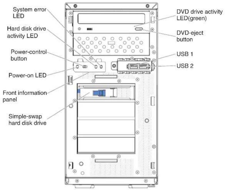
Figure5.Frontviewof4Uservermodelwithnon-hot-swappowersupplies(bezelremoved)
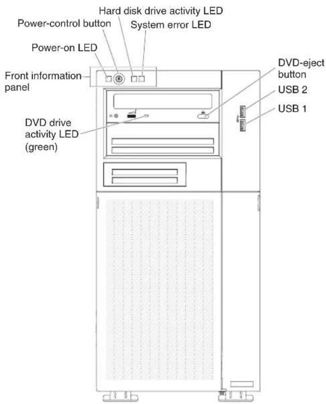
Figure6. Frontviewof5Uservermodelwithhot-swappowersupplies(lowerandupper bezelinstalled)
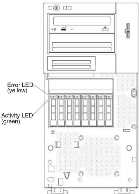
Figure7.Frontviewof5Usermodelwithhot-swappowersupplies(lowerandupper bezelinstalled)(Eight2.5"harddiskdriveconfiguration)

Figure8.Frontviewof5Usermodelwithhot-swappowersupplies(lowerandupper bezelinstalled)(Four3.5"harddiskdriveconfiguration)
•Powercontrolbuttonandpower-onLED:
Pressthisbuttontoturntheserveronandoffmanually.Thestatesofthe power-onLEDareasfollows:
-Off:ACpowerisnotpresent,orthepowersupplyortheLEDitselfhas failed.
-Flashingrapidly(4timespersecond):Theserverispartiallyon,butnot readytobefullyturnedon.Thepower-controlbuttonisdisabled.Thiswill lastapproximately1to3minutes.
-Flashingslowly(oncepersecond):Theserverisreadytobeturnedon.You canpressthepower-controlbuttontototurnontheserver.
-Lit: Theserveristurnedon.
•HarddiskdriveactivityLEDs:
WhenthisLEDisflashing, it indicates that the associated hard disk drive is in use.
- System-errorLED:
WhenthysyellowLEDislit, it indicates that asystemerror has occurred. An LEDonthesystemboard might also belitto help isolate the error. See "Diagnostictools" on page 124 for additional information.
•USBconnectors:
ConnectUSBdevicestotheseconnectors.
•DVDejectbutton:
PressthisbuttontoreleaseaDVDorCDfromtheDVDdrive.
•DVDdriveactivityLED:
WhenthisLEDislit, it indicates that the DVD drive is in use.
•Hot-swapharddiskdriveactivityLED(somemodels):
Onsomeservermodels, eachhot-swapdrivehasaharddiskdriveactivityLED. WhenthisgreenLEDisflashing, itindicates that the drive is in use.
Whenthedriveisremoved, this LED also is visible on the SAS/SATA backplane, next to the drive connector. The backplane is the printed circuit board behind drive bays 4 through 7 on 3.5-inch hard disk drivemodels.
•Hot-swapharddiskdrivestatusLED(somemodels):
Onsomeservermodels, eachhot-swapharddiskdrivehasanyellowstatus LED. If this yellow status LED for a drive is lit, it indicates that the associated hard disk drive has failed.
IfanoptionalServeRAIDadapterisinstalledintheserverandtheLEDflashes slowly(oneflashpersecond),thedriveisbeingrebuilt.IftheLEDflashes rapidly(threeflashespersecond),theadapterisidentifyingthedrive.
Whenthedriveisremoved, thisLEDalsoisvisibleontheSAS/SATA backplane, belowthehot-swapharddiskdriveactivityLED.
Rearview
The following illustrations respectively show the controls, LEDs and connectors there are of the 4U and 5User models.
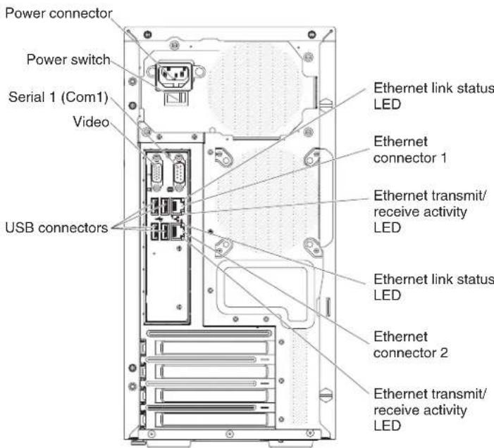
Figure9. Rearviewof4Uservermodelwithnon-hot-swappowersupplies(nopowersupply LEDspresent)
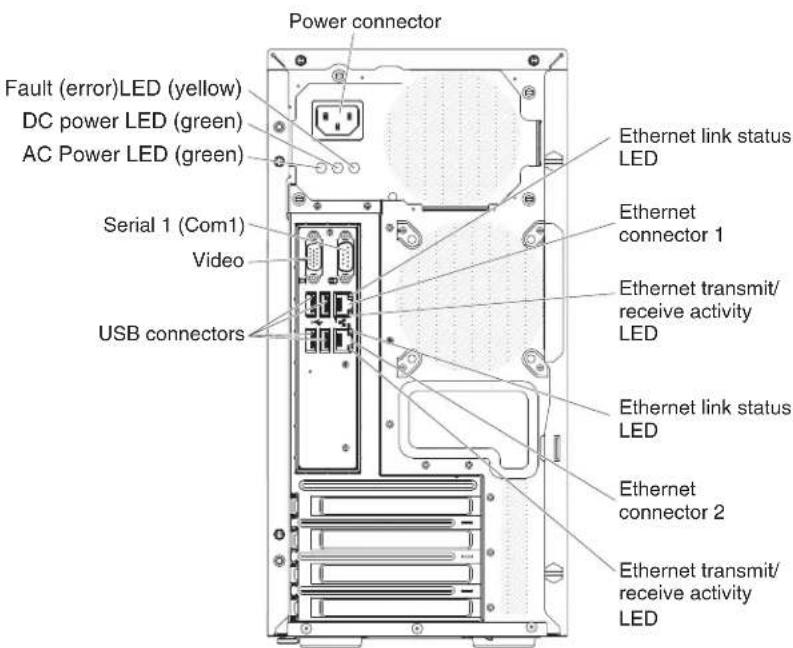
Figure10. Rearviewof4Uservermodelwithnon-hot-swappowersupplies(powersupply LEDspresent)

Figure 11. Rearviewof5Usermodelwithhot-swappowersupplies
•Powerconnector:Connectthepowercordtothisconnector.
- AC power LED: This green LED provides status information about the power supply. During typical operation, both the acanddc power LEDs are lit.
- DC power LED: This green LED provides status information about the power supply. During typical operation, both the acand dpower LEDs are lit.
- Fault-error LED: When this yellow LED is lit, it indicates that the power supply hasfailed..
- Serial connector: Connect a 9-pin serial device to this connector. The serial port is shared with the integrated management module II (IMM2). The IMM2 can take control of the shared serial port to direct serial traffic, using Serialover LAN(SOL).
•Videoconnector:Connectamonitortothisconnector.
- USBconnectors:ConnectUSBdevicestotheseclocknctors.
- NMI button: Press this button to force a nonmaskable interrupt to the microprocessor.Itallowsyoutobluescreentheserverandtakeamemory dump(usethisbuttononlywhendirectedbytheIBMservicesupport).You mighthavetouseapenortheendofastraightenedpapercliptopressthe button.
- Ethernet connector: Use either of these connectors to connect the server to a network. When you use the Ethernet1 connector, then network can be shared with the IMM2 through asinglenetworkable.
- Ethernet transmit/receive activity LED: This LED is on the Ethernet connector. WhenthisLEDisflashing, it indicates that there is activity between the server and thenetwork..
- Ethernet link status LED: This LED is on the Ethernet connector. When this LEDislit, it indicates that there is an active connection on the Ethernet port.
Serverpowerfeatures
When the server is connected to an ac powersource but is not turned on, the operating system does not run, and all core logic except for the integrated management module II (IMM2) is shutdown; however, the server can respond to requests from IMM2, such as a remoterequest to turn non the server.
The power-on LED flashesto indicate that the server is connected to an ac power source but is not turned on.
Turningontheserver
Usethisinformationtoturnontheserver.
Aboutthistask
Approximately5secondsaftertheserverisconnectedtoinputpower,oneormore fansmightstartrunningandthepower-onLEDflashesquickly.Approximately10 secondsaftertheserverisconnectedtoinputpower,thepower-onbuttonbecomes active.Afterthepower-onbuttonbecomesactive,thepower-onLEDflashes slowly.Youcanturnontheserverbypassingthepower-onbutton.
Procedure
- Pressthepower-onbuttontoturnontheserver.
- Theservercanalsobeturnedoninanyofthefollowingways:
- Ifapowerfailureoccurswhiletheserveristurnedon,theserverwillrestart automaticallywhenpowerisrestored.
- If your operating systems supports the WakeonLANfeature, the Wakeon LANfeature can turn on the server.
Whattodonext
- When4GBormoreofmemory(physicalorological)isinstalled,somememory isreservedforvariousystemresourcesandisunavailabletotheoperating system.Theamountofmemorythatisreservedforsystemresourcesdepends ontheoperatingsystem,theconfigurationoftheserver,andtheconfigured PCIoptions.
- Whenyouturnontheserverwithexternalgraphicaladaptersinstalled,the IBMlogodisplaysonthescreenafterapproximately3minutes.Thisisnormal operationwhilethesystemloads.
- Makesuretheleft-sidecoverisclosed.
Turningofftheserver
Usethisinformationtoturnofftheserver.
Aboutthistask
Whenyouturnofftheserverandleitconnectedtoinputpower,theservercan respondtorequeststotheserviceprocessor(theintegratedmanagementmodule), suchasaremoterequesttoturnontheserver.Whiletheserverremainsconnected toinputpower,oneormorefansmightcontinuetorun.Toremoveallpowerfrom theserver,youmustdisconnectitfromthepowersource.
Someoperatingsystemsrequireanorderlyshutdownbeforeyouturnoffthe server.Seeyouroperating-systemdocumentationforinformationaboutshutting downtheoperatingsystem.
Statement5

CAUTION:
The power control button on the device on turn off the electrical current supplied to the device. The device also is enough to have more than one power cord. Remove all electrical current from the device, ensure that all power cords are disconnected from the powersource.

Procedure
Theservercanbeturnedoffinanyofthefollowingways:
- Youcanturnofftheserverfromtheoperatingsystem,ifyouoperatingsystem supportthisfeature.Afteranorderlyshutdownoftheoperatingsystem,the serverwillturnoffautomatically.
- Youcanpressthepower-controlbuttontostartanorderlyshutdownofthe operatingsystemandturnofftheserver,ifyouroperatingsystemsupportthis feature.
- If the operating system stops functioning, you can press and hold the power-control button form more than 4 second to turn off the server.
- TheservercanbeturnedoffbyWakeonLANfeaturewiththefollowing limitation:
•The integrated management module II (IMM2) canturnoff the server as an automatic responsetoacritical system failure.
Chapter2.Installingoptionaldevices
Thischapterprovidesdetailedinstructionsforinstallingoptionalhardwaredevices intheserver.
Beforeyoubegin
In addition to the instructions in this chapter for installing optional hardware devices, updating the firmware and device drivers, and completing the installation, IBM Business Partners must also complete the steps in "Instructions for IBM Business Partners" on page 28.
Important: To help ensure that the device that you install work correctly and do not introduce problems, observ the following precautions.
Procedure
- Makesurethattheserverandtheinstalledfirmwarelevelssupportthedevices
thatyouareinstalling.Ifnecessary,updatetheUEFIandIMMfirmwareand
anyotherfirmwarethatisstoredonthesystemboard.Forinformationabout
wherefirmwareisstoredintheserver,see"Updatingthefirmware"onpage -
Foralistofsupportedoptionaldevicesfortheserver,see
http://www.ibm.com/systems/info/x86servers/serverproven/compat/us. -
Usethebestpracticestoapplycurrentfirmwareanddevice-driverupdatesfor
theserverandoptionaldevices.Todownloadthe"IBMSystemxFirmware
UpdateBestPractices"document,gotowww.ibm.com/support/entry/portal/
docdisplay?Indocid=MIGR-5082923&brandind=5000008.Additionalhintsand
tipsareavailablefromthefollowingsites:
•IBMsupport:http://www.ibm.com/supportportal/
•Systemxconfigurationtools:http://www.ibm.com/systems/x/hardware/
configtools.html
- Before you install optional hardware devices, makes sure that the server is
workingcorrectly.Starttheserverandmakesurethattheoperatingsystem
starts,ifanoperatingsystemisinstalled,orthata19990305errorcodeis
displayed, indicating that an operating system was not found but the server is otherwise working correctly. If the server is not working correctly, see
"RunningDSAPrebootdiagnosticprograms"onpage138forinformation
abouthowtorundiagnostics.
- Follow the installation procedures in this chapter and use the correct tools.
Incorrectly installed devices can cause system failure because of damaged pins
insocketsorconnectors,loosecabling,orloosecomponents.
InstructionsforIBMBusinessPartners
Instructions for IBM Business Partner, verifying the newly installed devices by running the Dynamic System Analysis (DSA) stress test.
Inadditiontotheinstructionsinthischapterforinstallingoptionalhardware devices,updatingfirmwareanddevicedrivers,andcompletingtheinstallation, IBMBusinessPartnersmustalsocompletethefollowingsteps:
-
After you have confirmed that the server starts correctly and recognizes the newly installed devices and that no error LEDs are lit, run the Dynamic System Analysis (DSA) stress test. For information about using DSA, see "IBM Dynamic System Analysis" on page 136.
-
Shutdownandrestarttheservermultipletimestoensurethattheserveris correctlyconfiguredandfunctionscorrectlywiththenewlyinstalleddevices.
-
SavetheDSAlogasafileandsendittoIBM.Forinformationabout transferringdataandlogs,see"HowtosendDSAdatatoIBM."
-
Toshiptheserver, repackageitintheoriginal undamaged packing material and observe IBM procedures for shipping.
SupportinformationforIBMBusinessPartnersisavailableathttp://www.ibm.com/partnerworld.
HowtosendDSAdatatoIBM
UsetheIBMEnhancedCustomerDataRepositorytosenddiagnosticdatatoIBM.
BeforeyousenddiagnosticdatatoIBM,readthetermsofuseat http://www.ibm.com/de/support/ecurep/terms.html.
You can use any of the following method to send diagnostic data to IBM:
-Standardupload:http://www.ibm.com/de/support/ecurep/send_http.html
- Standard upload with the system serial number: http://www.ecurep.ibm.com/app/upload_hw
- Secureupload:http://www.ibm.com/de/support/ecurep/send_http.html#secure
- Secure upload with the system serial number: https://www.ecurep.ibm.com/app/upload_hw
Servercomponents
Thesectionshowsthemajorcomponentsintheserver.
The following illustrations show the server components in 4 User models with non-hot-swappowersupplies. The illustrations in this document might differ slightly from your hardware.
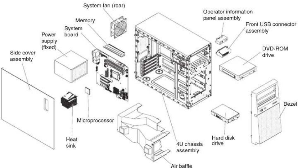
Figure12.Servercomponentsfor4Uservermodelswithnon-hot-swappowersupplies
The following illustrations show the server components in 5 User models with hot-swappowersupplies. The illustrations in this document might differs lightly from your hardware.

Figure 13. Servercomponentsfor5Uservermodelswithhot-swappowersupplies
Blueonaccomponentindicatestouchpoints,whereyoucangripthecomponentto removeitfromorinstallitintheserver,openorclosealatch,andsoon.
Orangeonaccomponentoranorangelabelonornearacomponentindicates that thecomponentcanbehot-swapped,whichmeansthatiftheserverandoperating systemsupporthot-swapcapability,youcanremoveorinstallthecomponent whiletheserverisrunning.(Orangecanalsoindicatetouchpointsonhot-swap components.)Seetheinstructionsforremovingorinstallingaspecifichot-swap componentforanyadditionalproceduresthatyoumighthavetoperformbefore youremoveorinstallthecomponent.
System-boardinternalconnectors
Thissectioncontainsinformationregardingthesystemboardinternalconnectors.
The following illustrations show the internal connectors on the system board.

Figure14. Internalconnectorsonsystemboard
System-boardexternalconnectors
Thissectioncontainsinformationregardingthesystemboardexternalconnectors.

Figure15.Externalconnectorsonsystemboard
System-boardswitchesandjumpers
Thissectioncontainsinformationregardingthesystemboardswitchesand jumpers.

Figure16.Locationanddescriptionofswitchesandjumpers
The following table describes the function of switches and jump person the system board.
Table2. Systemboardswitchesandjumpersdefinition
| JumpernumberJumppernameJumpersetting | ||
| J12Lowsecurityjumper | •Pins1and2:Normal(default).•Pins2and3:Activatelowsecurity. | |
| OVR1IMMSPIenablejumper | •Pins1and2:Disabled.•Pins2and3:EnableIMMSPIhalf ROMdefault) | |
| J16UEFIbootbackupjumper | •Pins1and2:Bootfromprimary BIOSpage(default).•Pins2and3:Bootfrombackup BIOSpage. | |
| CLRRTC1ClearCMOSjumper | •Pins1and2:KeepCMOSdata (default).•Pins2and3:ClearCMOSdata. | |
| Note:1. Ifnojumperispresent,theserverrespondsasdefault.2. Changing the position of the boot block jumper from pins 1 and 2 to pins 2 and 3 for 5 seconds before the server isturnedonalterswhichflashROMpageisloaded.Donotchangethejumperpinpositionaftertheserveris turnedon.Thiscancauseanunpredictableproblem. | ||
Important:
- Before you change an any switch settings or move any jumpers, turn off the server; then, disconnect all power cords and external cables. Review the information in "safety" on page 26, "Handling static-sensitive devices" on page 35, "Turning off the server" on page 26.
- Anysystem-boardswitchorjumperblocksthatarenotshowninthe illustrationsinthisdocumentarereserved.
- If there is unclear protectivesticker on the top of the switch blocks, you must remove and discard it to access the switches.
System-boardLEDs
ThissectioncontainsinformationregardingthesystemboardLEDs.
The following illustrations show the LED sonthesystem board.

Figure17.LEDlocationonsystemboard
Note: When you disconnect the powersource from the server, you lose the ability to view the LEDs because the LEDs are not lit when the powersource is removed. Before you disconnect the powersource, make an note of which LEDs are lit, including the LED sthatareliton the operation information panel and LEDs inside the server on the system board.
Installationguidelines
UsetheinstallationguidelinestoinstalltheIBMSystemx3100M5Type5457.
Attention: Staticelectricity that is released to internal server components when the server is powered on might cause the system to halt, which might result in the loss of data. To avoid this potential problem, always use an electrostatic discharge wrist strap or other groundingsystem when removing or installing a hot-swap device.
Before you install optional devices, read the following information:
- Readthesafetyinformationin "Safety" onpageviandtheguidelinesin "Workinginsidetheserverwiththepoweron" onpage37,and"Handling static-sensitivedevices" onpage37.Thisinformationwillhelpyouworksafely.
• Makesurethatthedevicesthatyouareinstallingaresupported.Foralistof supportedoptionaldevicesfortheserver,seehttp://www.ibm.com/systems/info/x86servers/serverproven/compat/us
- Whenyouinstallyournewserver,taketheopportunitytodownloadandapply themostrecentfirmwareupdates.Thisstepwillhelptoensurethatanyknown issuesareaddressedandthatyourserverisreadytofunctionatmaximum levelsofperformance.Todownloadfirmwareupdatesforyourserver,goto http://www.ibm.com/support/fixcentra.
Important: Some clusters solutions requires specific code levels or coordinated code updates. If the device is part of clusters solution, verify that the latest level of code is supported for the clusters solution before you update the decode.
For additional information about tools for updating, managing and deploying firmware, seethe Tools Center for Systemx and Blade Center at http://www.ibm.com/support/entry/portal/docdisplay?Indocid=TOOL CENTER
- Beforeyouinstalloptionalhardware,makesurethattheserverisworking correctly.Starttheserver,andmakesurethattheoperatingsystemstarts,ifan operatingsystemisinstalled,orthata19990305errorcodeisdisplayed, indicatingthatanoperatingsystemwasnotfoundbuttheserverisotherwise workingcorrectly.Iftheserverisnotworkingcorrectly,see"RunningDSA Prebootdiagnosticprograms"onpage138forinformationabouthowtorun diagnostics.
- Observegoodhousekeepingintheareawhereyouareworking.Placeremoved coversandotherpartsinasafeplace.
- Donotattempttoliftanobjectthatyouthinkistooheavyforyou.Ifyouhave toliftaheavyobject,observethefollowingprecautions:
-Makesurethatyoucanstandsafelywithoutslipping.
-Distributetheweightoftheobjectequallybetweenyourfeet.
-Useaslowliftingforce.Nevermovesuddenlyortwistwhenyouliftaheavy object.
-To avoid straining them muscles in your back, lift by standing or bypassing up with your leg muscles.
- Makesurethatyouhaveanadequatenumberofproperlygroundedelectrical outletsfortheserver,monitor,andotherdevices.
- Backupallimportantdatabaseforeyoumakechangestodiskdrives.
- Haveasmallflat-bladescrewdriveravailable.
- ToviewtheerrorLEDsonthesystemboardandinternalcomponents,leavethe serverconnectedtopower.
- Youdonothavetoturnofftheservertoinstallorreplacehot-swappower supplies, hot-swapfans, or hot-plugUniversalSerialBus(USB) devices. However, you must turn off the server before you perform any step that involves removing installing adapter cables and you must disconnect the powers from the server before you perform any step that involve removing installing a risercard.
- Blueonaccomponentindicatestouchpoints,whereyoucangripthecomponent toremoveitfromorinstallitintheserver,openorclosealatch,andsoon.
- Orangeancomponentoranorangelabelonornearacompontindicates thatthecomponentcanbehot-swapped,whichmeansthatiftheserverand operatingsystemsupporthot-swapcapability,youcanremoveorinstallthe componentwhiletheserverisrunning.(Orangecanalsoindicatetouchpoints onhot-swapcomponents.)Seetheinstructionsforremovingorinstallinga specifichot-swapcomponentforanyadditionalproceduresthatyoumighthave toperformbeforeyouremoveorinstallthecomponent.
- When you are finished working on the server, reinstall all safety shields, guards, labels, and ground wires.
Systemreliabilityguidelines
Thesystemreliabilityguidelinestoensurepropersystemcooling.
To help ensure propersystem cooling and system reliability, makes sure that the following requirements are met:
•Eachofthedrivebayshasadriveorafillerpanelandelectromagnetic compatibility(EMC)shieldinstalledinit.
- If the server has redundant power, each of the power supply by bayshas a power supply installed init.
- Thereisadequatespacearoundtheservertoallowtheservercoolingsystemtoworkproperly.Leaveapproximately50mm(2.0in.)ofopenspacearoundthefontandrearoftheserver.Donotplaceobjectsinfrontofthefans.Forpropercoolingandairflow,replacetheservercoverbeforeyouturnontheserver.Operatingtheserverforextendedperiodsoftime(morethan30minutes)withtheservercoverremovedmightdamageservercomponents.
- You have followed the cabling instruction that comewith optional adapters.
- Youhavereplacedafailedfanassoonaspossible.
- Youhavereplacedahot-swapdrivewithin2minutesofremoval.
- Youdonotoperatetheserverwithouttheairbaffleinstalled. Operating the serverwithouttheairbafflemightcausethemicroprocessortooverheat.
Workinginsidetheserverwiththepoweron
Guidelinestoworkinsidetheserverwiththepoweron.
Attention: Staticelectricity that is released to internal server components when the server is powered on might cause the server to hold, which might result in the loss of data. To avoid this potential problem, always use an electrostatic discharge wrist strap or other groundings system when you work inside the server with the poweron.
Theserversupportshot-plug, hot-add, and hot-swap devices and is designed to operates safely while it is turned on and the server covers removed. Follow these guidelines when you work inside a server that is turned on:
Note: Inordertoworkinsidetheserverwiththepoweron, you havetodisable thepowercut-offswitchbeforeremovingtheservercover.
- Avoidwearingloose-fittingclothingonyourforearms.Buttonlong-sleeved shirtsbeforeworkinginsidetheserver;donotwearcufflinkswhileyouare workinginsidetheserver.
- Donotallowyournecktieorscarftohanginsidetheserver.
- Removejewelry, such as bracelets, necklaces, rings, and loose-fitting wrist watches.
- Removeitemsfromyourshirtpocket,suchaspensandpencils,thatcouldfall intotheserverasyouleanoverit.
- Avoiddroppinganymetallicobjects,suchaspaperclips,hairpins,andscrews, intotheserver.
Handlingstatic-sensitivedevices
Usethisinformationtohandlestatic-sensitivedevices.
Attention: Staticelectricity and damage the server and other electronic devices. To avoid damage, keep static-sensitive devices in their static-protective packages until you are ready to install them.
Toreducethepossibility of damage from electrostatic discharge, observ the following precautions:
- Limityourmovement.Movementcancausestaticelectricitytobuilduparound you.
•Theuseofagroundingsystemisrecommended. Forexample, wearan electrostatic-dischargewriststrap, ifoneisavailable. Alwaysusean electrostatic-dischargewriststraporothergroundingsystemwhenworking insidetheserverwiththepoweron. - Handlethedevicecarefully, holdingitbyitsedgesoritsframe.
- Donottouchsolderjoints,pins,orexposedcircuitry.
- Donotleavethedevicewhereotherscanhandleanddamageit.
- While the device is still its static-protective package, touch it to an unpainted metals surface on the outside of the server for at least 2 seconds. This drains static electricity from the package and from your body.
- Removethedevicefromitspackageandinstallitdirectlyintotheserver withoutsettingdownthedevice.Ifitisnecessarytosetdownthedevice,putit backintoitsstatic-protectivepackage.Donotplacethedeviceontheserver coveroronametalsurface.
•Takeadditionalcarewhenhandlingdevicesduringcoldweather.Heating reducesindoorhumidityandincreasesstaticelectricity.
Removingthesidecover
Usethisinformationtoremovethesidecover.
Attention: Operating the server perform more than 30 minutes with the sidecover removed might damage server components. For proper cooling and airflow, install the sidecover before output nontheserver.
For4Uservermodelswithnon-hot-swappowersupplies,completethefollowing stepstoremovethesidecover.Forthe5Uservermodelwithhot-swappower supplies,pleaseseethenextsub-section.
- Readthesafetyinformationin"Safety"onpageviiand"Installation guidelines"onpage35.
- Turnofftheserverandperipheraldevicesanddisconnectthepowercordsandallexternalcables(see"Turningofftheserver"onpage26).
- Carefullyturntheserveronitssidesothatitislyingflat,withthecoverfacing up.
Attention: Donotallowtheservertofallover.
- Unscrewthetwochassisscrewsontherearsideoftheserver.
- Pulltherearsidecoverhandleandpushthefrontsidecoverhandleatthe sametime.
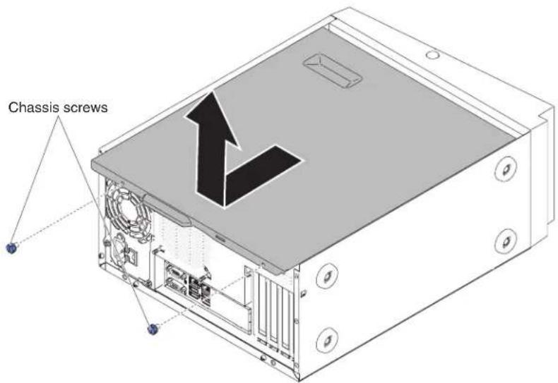
Figure18.Sidecoverremovalfor4Uservermodelwithnon-hot-swappowersupplies
Attention: For proper cooling and airflow, replacetheservercover before you turnontheserver.
- If you are instructed to return the side cover, follow all packaging instructions, and use an y packaging materials for shipping that a resupplied to you.
Forthe5Uservermodelwithhot-swappowersupplies,completethefollowing stepstoremovethesidecover.For4Uservermodelswithnon-hot-swappower supplies,pleaseseetheabovesub-section.
- Readthesafetyinformationin"Safety"onpageviand"Installation guidelines"onpage35.
- Turnofftheserverandperipheraldevicesanddisconnectthepowercordsandallexternalcables(see"Turningofftheserver"onpage26).
- Unlockthesidecover; then, pressthecover-releaselatchdown (asshownin theillustration) toremovethecover.

Figure19. Sidecoverremovalfor5Uservermodelwithhot-swappowersupplies
Attention: For proper cooling and airflow, replacetheservercover before you turn on the server.
- If you are instructed to return the side cover, follow all packaging instructions, and use any packaging materials for shipping that aresupplied to you.
Removingtheairbaffle
Thisprocedureappliesonlyto4Uservermodelswithnon-hot-swappower supplies.
Toremovetheairbaffle, completethefollowingsteps.
- Readthesafetyinformationin"Safety"onpageviand"Installation guidelines"onpage35.
- Turnofftheserverandperipheraldevicesanddisconnectthepowercordsandallexternalcables(see"Turningofftheserver"onpage26).
- Unlockandremovethesidecover(see"Removingthesidecover" on page 38).
- Carefullyturntheserveronitssidesothatitislyingflat,withthesystem boardfacingup.
Attention: Donotallowtheservertofallover.
- Grasphetopoftheairbaffleandliftitoutoftheserver.

Figure20. Airbaffleremovalfor4Uservermodelwithnon-hot-swappowersupplies
Attention: For proper cooling and airflow, reinstall the airbaffle, making sure all cables are out of the way, before you turn on the server. Operating the server with the airbaffle removed might damage server components.
- If you are instructed to return the air baffle, follow all packaging instructions, and use an y packaging materials for shipping that a resupplied to you.
Removingthebezel
Thisprocedureappliesonlyto4Uservermodelswithnon-hot-swappower supplies.
Whenyouworkwithsomedeviceson4Uservermodelswithnon-hot-swappower supplies,suchasthedrivesinbays3through6,youmustfirstremovethebezelto accessthedevices.
- Readthesafetyinformationin"Safety"onpageviand"Installation guidelines"onpage35.
- Pressthebuttononthecleftedgeofthebezel;then,rotatetheleftsideofthe bezelawayfromtheserveruntildisengagesandsetitaside.
Note: When rotating the bezel to acertain point, it may automatically disengage from the chassis.

natural_image
Line drawing of a desktop computer tower with a blue indicator button (no text or symbols)Figure21. Bezelremovalfor4Uservermodelwithnon-hot-swappowersupplies(1)
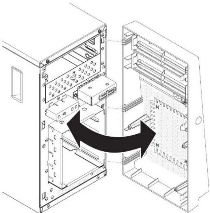
natural_image
Diagram of a computer tower internal structure showing internal components and an arrow indicating a transformation or assembly (no text or symbols present)Figure22. Bezelremovalfor4Uservermodelwithnon-hot-swappowersupplies(2)
- If you are instructed to return the bezel, follow all packaging instructions, and use anYPackaging materials for shipping that a resupplied to you.
Removingthelowerbezel
Thisprocedureappliesonlytothe5Uservermodelwithhot-swappowersupplies.
Toaccesstheharddiskdrivesonthe5Uservermodelwithhot-swappower supplies,youmustfirstremovethelowerbezel.
- Readthesafetyinformationin"Safety"onpageviand"Installation guidelines"onpage35.
- If you are replacing an on-hot-swap component, turn off the server and all attached devices; then, disconnect all power cords and external cables.
- Presstheblue-coloredreleasebuttonontherightsideofthelowerbezeland rotatethelowerbezeldownwardtodisengagefromthechassis.
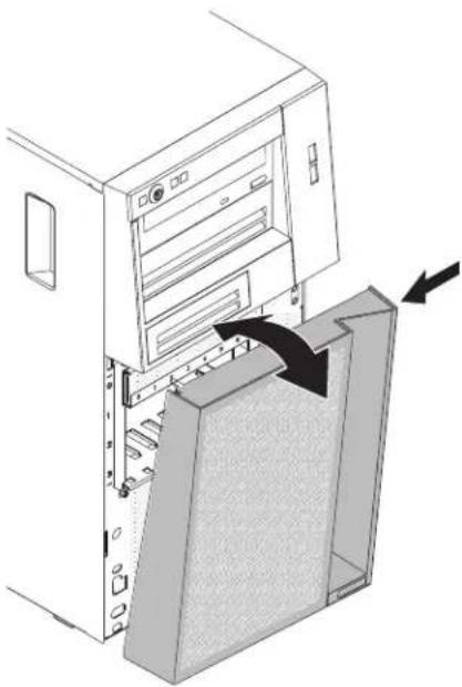
natural_image
Diagram of a computer tower with an open storage unit and a closed panel, showing internal components and directional arrows (no text or symbols)Figure23. Lowerbezelremovalfor5Uservermodelwithhot-swappowersupplies
- If you are instructed to return the lower bezel, follow all packaging instructions, and use an app packaging materials for shipping that a resupplied to you.
Thisprocedureappliesonlytothe5Uservermodelwithhot-swappowersupplies.
ToaccesstheDVDdriveortapedriveonthe5Uservermodelwithhot-swap powersupplies,youmustfirstremovetheupperbezeltoaccessthedevices.
Toremovetheupperbezelonthe5Uservermodelwithhot-swappowersupplies, completethefollowingsteps.
- Readthesafetyinformationin"Safety"onpageviand"Installation guidelines"onpage35.
- If you are replacing an on-hot-swap component, turn off the server and all attached devices; then, disconnect all power cords and external cables.
- Unlockandremovethesidecover(see"Removingthesidecover" on page 38).
- Removethelowerbezel(see"Removingthelowerbezel"onpage42).
- Carefullypullthetwobezelclipsontheleftsideoftheupperbezel;then, rotatetheupperbezeltotherightsideoftheservertodisengagethetwo right-sidetabsfromthechassis.

Figure24. Lowerbezelremovalfor5Uservermodelwithhot-swappowersupplies
- If you are instructed to return the upper bezel, follow all packaging instructions, and use an y packaging materials for shipping that a resupplied to you.
Installingamemorymodule
Usethisinformationtoinstallamemorymodule
The following notes describe the types of dual in line memory modules (DIMMs) that the servers supports and other information that you must consider when you install DIMMs (see "System-board internal connectors" on page 30).
If you are replacing an memory module, makes sure that:
- Theserversupportsindustry-standard,1066,1333and1600MHz,PC3-12800 (single-rankordual-rank)double-data-rate3(DDR3),registeredorunbuffered, synchronousdynamicrandom-accessmemory(SDRAM)dualinlinememory modules(DIMMs)witherrorcorrectingcode(ECC).Foralistofsupported optionsfortheserver,seehttp://www.ibm.com/systems/info/x86servers/serverproven/compat/us;then,selectyourcountryandnavigatetothelistof optionsfortheserver.
- Themaximumamountofmemorythattheserversupportsisdependentonthe typeofmemorythatyouinstallintheserver.
•Theamountofusablememoryisreduced,dependingonthesystem configuration.Acertainamountofmemorymustbereservedforsystem resources.Toviewthetotalamountofinstalledmemoryandtheamountof configuredmemory,runtheSetuputility.Foradditionalinformation,see"Using theSetuputility"onpage98. - Themaximumoperatingspeedoftheserverisdeterminedbytheslowest DIMMintheserver.
- If you install a pair of DIMMsinDIMMconnectors1 and 3, these and speed of the DIMMsthat you install in DIMMconnectors1 and 3 must match each other. However, they donothavetobethesamesize and speed as the DIMMs that are installed in DIMMconnectors2 and 4.
- YoucanusecompatibleDIMMsfromvariousmanufacturersinthesamepair.
- When you install or remove DIMMs, the server configuration information changes. When you restart the server, the system displays message that indicates that the memory configuration has changed.
Attention: Staticelectricity that is released to internal server components when the server is powered on might cause the server vertostop, which could result in the loss of data. To avoid this potential problem, always use an electrostatic-dischargewrist strap or other groundings system when working inside the server with the poweron.
- ThespecificationsofaDDR3DIMMareonalabelontheDIMM, inthe followingformat.
ggg eRxff-PC3-wwwwwm-aa-bb-cc where:
-gggisthetotalcapacityoftheDIMM(forexample,1GB,2GB,or4GB)
-eisthenumberofranks
-1=single-rank
-2=dual-rank
-4=quad-rank
-ffisthedeviceorganization(bitwidth)
-4=x4organization(4DQlinesperSDRAM)
-8=x8organization
-16=x16organization
- wwwwwistheDIMMbandwidth, in MBps
-8500=8.53GBps(PC3-1066SDRAMs, 8-byteprimarydatabus)
-10600=10.66GBps(PC3-1333SDRAMs, 8-byteprimarydatabus)
-12800=12.8GBps(PC3-1600SDRAMs, 8-byteprimarydatabus)
-mistheDIMMtype
-E=UnbufferedDIMM(UDIMM)withECC(x72-bitmoduledatabus)
-R=RegisteredDIMM(RDIMM)
-U=UnbufferedDIMMwithnoECC(x64-bitprimarydatabus)
-aaistheCASlatency, inclocksatmaximumoperatingfrequency
-bbistheJEDECSPDRevisionEncodingandAdditionslevel
-ccisthereferencedesignfileforthedesignoftheDIMM
-distherevisionnumberofthereferencedesignoftheDIMM
Note: TodeterminethetypeofaDIMM, seethelabelontheDIMM. The informationonthelabelisintheformatxxxxxnRxxxPC3-xxxxx-xx-xx-xxx. The numeralinthesixthnumericalpositionindicateswhethertheDIMMis single-rank(n=1)ordual-rank(n=2).
UnbufferedDIMMs(UDIMMs)
The following notes provide information that you must consider when you install UDIMMs:
- ThememorychannelsrunatthelowestcommonfrequencyoftheDIMMs installed.
•TheUDIMMoptionsthatareavailablefortheserverare1GB,2GB,4GB,and 8GB(whenavailable)DIMMs. - Theserversupportsuptotwosingle-rankordual-rankUDIMMsperchannel.
The following table lists supported UDIMM population.
Table3.SupportedUDIMMpopulationperchannel
| DIMM connectorsper channel | DIMMs installedineach channelDIMMtype | eDIMMspeed | Ranksper DIMM(any combination) | |
| 21Unbuffered | DDR3ECC | 1333,1600Single-rank,dual-rank | ||
| 22Unbuffered | DDR3ECC | 1333,1600Single-rank,dual-rank |
The following table lists the maximum DIMM population using ranked UDIMMs.
Table4.MaximummemorypopulationusingrankedUDIMMs(dependingonyourmodel)
| Numberof UDIMMsDIMMtype | SizeTotalmemory | ||
| 4 | Single-rankUDIMMs | 1GB | 4GB |
| 4 | Dual-rankUDIMMs | 2GB | 8GB |
| 4 | Dual-rankUDIMMs | 4GB | 16GB |
| 4 | Dual-rankUDIMMs | 8GB(when available) | 32GB |
The following tables show the UDIMM memory population rule to optimize the system performance.
Table5.UDIMMpopulationrule
| DIMMconnector1DIM | Mconnector2DIMMconnector3DIMMconnector4 | |
| PopulatedEmptyEmpty | Empty | |
| PopulatedEmptyPopulated | Empty | |
| PopulatedPopulatedPopulatedPopulated | ||
The following illustrations show the location of the DIMM connector on the systemboard.
Note: The illustrations in this document might differs slightly from your model.

Figure25.DIMMconnectorsonsystemboard
Attention: Staticelectricity that is released to internal server components when the server is powered on might cause the server to hold, which might result in the loss of data. To avoid this potential problem, always use an electrostatic discharge wrist strap or other groundings system when you work inside the server with the poweron.
ToinstallaDIMMon4Uservermodelswithnon-hot-swappowersupplies, completethefollowingsteps.Forthe5Uservermodelwithhot-swappower supplies,pleaseseethenextsub-section.
-
Readthesafetyinformationin"Safety"onpageviand"Installation guidelines"onpage35.
-
Turnoff the server and peripheral devices, and disconnect the power cords and all external cables.
-
Carefullyturntheserveronitssidesothatitislyingflat,withthecover facingup.
Attention: Donotallowtheservertofallover. -
Removethesidecover(see "Removingthesidecover" on page 38).
-
Removetheairbaffle(see "Removingtheairbaffle" on page 39).
-
LocatetheDIMMconnectorsonthesystemboard.Determinetheconnectors intowhichyouwillinstalltheDIMMs.InstalltheDIMMsinthesequence showninthefollowingtable.
Table6.DIMMinstallationsequence
| NumberofDIMMsInstallationsequence(connectors) | |
| FirstpairofDIMMs1,3 | |
| SecondpairofDIMMs2,4 | |
-
Opentheretainingclipsand,ifnecessary,removeanyexistingDIMM. Attention:ToavoidbreakingtheretainingclipsordamagingtheDIMM connectors,openandclosetheclipsgently.
-
Touchthestatic-protectivepackagethatcontainstheDIMMtoanyunpainted metalsurfaceontheoutsideoftheserver.Then,removetheDIMMfromthe package.
-
TurntheDIMMsothattheDIMMkeysaligncorrectlywiththeconnector.
-
InserttheDIMMintotheconnectorbyaligningtheedgesoftheDIMMwith theslotsattheendsoftheDIMMconnector.
-
FirmlypresstheDIMMstraightdownintotheconnectorbyapplyingpressure onbothendsoftheDIMMsimultaneously.Theretainingclipssnapinto the lockedpositionwhentheDIMMisfirmlyseatedintheconnector.
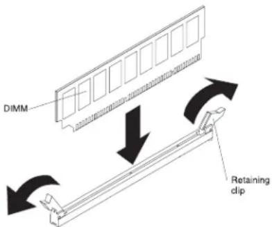
Figure26.DIMMinstallation
Note: If thereisagapbetween the DIMM and theretaining clips, the DIMM has not been correctly inserted; open theretaining clips, remove the DIMM, and then reinsert it.
- If you have other device to install, do on now. Otherwise, goto "Completing the installation" on page 82.
ToinstallaDIMMonthe5Uservermodelwithhot-swappowersupplies, completethefollowingsteps.For4Uservermodelswithnon-hot-swappower supplies,pleaseseetheabovesub-section.
- Readthesafetyinformationin"Safety"onpageviand"Installation guidelines"onpage35.
- Turnoff the server and peripheral devices, and disconnect the power cords and all external cables.
- Unlockandremovethesidecover(see"Removingthesidecover" on page 38).
- Carefullyturntheserveronitssidesothatitislyingflat,withthesystem boardfacingup.
Attention: Donotallowtheservertofallover.
- LocatetheDIMMconnectorsonthesystemboard.Determinetheconnectors intowhichyouwillinstalltheDIMMs.InstalltheDIMMsinthesequence showninthefollowingtable.
Table7.DIMMinstallationsequence
| NumberofDIMMsInstallationsequence(connectors) | |
| FirstpairofDIMMs1,3 | |
| SecondpairofDIMMs2,4 | |
- Opentheretainingclipsand, if necessary, remove any existing DIMM. Attention: To avoid breaking the retaining clips or damaging the DIMM connectors, open and closethe clips gently.
- Touchthestatic-protectivepackagethatcontainstheDIMMtoanyunpainted metalsurfaceontheserver.Then,removethenewDIMMfromthepackage.
- TurntheDIMMsothattheDIMMkeysaligncorrectlywiththeconnector.
- InserttheDIMMintotheconnectorbyaligningtheedgesoftheDIMMwith theslotsattheendsoftheDIMMconnector.
- Firmlypress the DIMM straightdown into the connector by applying pressure on both end of the DIMMs simultaneously. Theretaining clipssnap into the locked position when the DIMMis firmly seated in the connector.

Figure27.DIMMinstallation
Note: If there is a gap between the DIMM and theretaining clips, the DIMM has not been correctly inserted; open theretaining clips, remove the DIMM, and then reinsert it.
- If you have other device to install, do onow. Otherwise, goto "Completing the installation" on page 82.
Installingdrives
Usethisinformationtoinstalldrives.
Dependingontheservermodel,aDVD-ROMormultiburnerdrivemightbe installedintheserver.For4Uservermodelswithnon-hot-swappowersupplies, theserversupportsuptofour3.5-inchsimple-swapSATAharddiskdrives (dependingonthemodel).Forthe5Uservermodelwithhot-swappowersupplies, theserversupportsuptoeight2.5"hot-swapSATA/SASharddiskdrivesorfour 3.5"hot-swapSATA/SASharddiskdrives.
The following figures show the location of the four 3.5" simple-swapharddisk drivebays in the 4User vermodel with non-hot-swappowersupplies.

Figure28.Locationofthefour3.5"simple-swapharddiskdrivebaysinthe4Uservermodel withnon-hot-swappowersupplies
The following figures show the location of the eight 2.5"hot-swapharddisk drive baysinthe5Uservermodel with hot-swappowersupplies.

Figure29.Locationoftheeight2.5"hot-swapharddiskdrivebaysinthe5Uservermodel withhot-swappowersupplies
The following figures show the location of the four 3.5" hot-swaphard disk drive bays in the 5 User model with hot-swappowers supplies.

Figure30.Locationofthefour3.5"hot-swapharddiskdrivebaysinthe5Uservermodel withhot-swappowersupplies
The following notes describe the types of drivesthat the servers supports and other information that you must consider when installing a drive:
- Locatethedocumentationthatcomeswiththedriveandfollowthose instructionsinadditiontotheinstructionsinthischapter.
- Makesurethatyouhaveallthecablesandotherequipmentthatarespecifiedin thedocumentationthatcomeswiththedrive.
- Selectthebayinwhichyouwanttoinstallthedrive.
- Check the instruction that comewith the drivetodeterminewhethery you have to set any switches or jump person the drive.
•Theelectromagneticinterference(EMI)integrityandcoolingoftheserverare protectedbyhavingallbaysandPCIandPCIExpressslotscoveredoroccupied. Whenyouinstalladrive,PCI,orPCIExpressadapter,savetheEMCshieldand fillerpanelfromthebayorPCIadapterorPCIExpressadapterslotcoverinthe eventthatyoulaterremovethedevice.
•Foracompletelistofsupportedoptionsfortheserver,seehttp://www.ibm.com/systems/info/x86servers/serverproven/compat/us
InstallingaDVDdrive
UsethisinformationtoinstallaDVDdrive
If you are replacing are moved drivewith anew drive, makes sure that:
- You have all the cables and other equipment that are specified in the documentation that comes with thenew drive.
- Youhavecheckedtheinstructionsthatcomewiththenewdrivetodetermine whetheryoumustsetanyswitchesorjumpersinthedrive.
- Youhaveremovedtheblueopticaldriverailsfromthesideoftheolddriveand havethemavailableforinstallationonthenewdrive.
Note: If you are installing a drivethat contains alaser, observ the following safety precautions.
Statement3

CAUTION:
When laser products(suchasCD-ROMs, DVD drives, fiberoptic devices, or transmitters) are installed, not the following:
- Donotremovethecovers.Removingthecoversofthelaserproductcould resultinexposuretohazardouslaserradiation.Therearenoserviceableparts insidethedevice.
- Useofcontrolsoradjustmentsorperformanceofproceduresotherthanthose specifiedhereinmightresultinhazardousradiationexposure.

DANGER
SomelaserproductscontainanembeddedClass3AorClass3Blaserdiode.
Notethefollowing.Laserradiationwhenopen.Donotstareintothebeam, donotviewdirectlywithopticalinstruments,andavodidirectexposure to thebeam.

Class 1 Laser Product
Laser Klasse 1
Laser Klass 1
Luokan 1 Laserlaite
ToinstallaDVDdriveon4Uservermodelswithnon-hot-swappowersupplies, completethefollowingsteps.Forthe5Uservermodelwithhot-swappower supplies,pleaseseethenextsub-section.
-
Readthesafetyinformationin"Safety"onpageviand"Installation guidelines"onpage35.
-
Follow the instruction that comewith the drivetosetjumpersorswitches, if there are any.
Note: You might find it asiert install thenew drive from the front and then attach the cables.
-
Turnoff the server and all peripheral devices; then, disconnect the power cords and all external cables.
-
Removethebezel(see "Removingthebezel" on page 40).
-
Carefullyturntheserveronitssidesothatitislyingflat,withthecover facingup.
Attention: Donotallowtheservertofallover.
-
Removethesidecover(see "Removingthesidecover" on page 38).
-
Touchthestatic-protectivepackagethatcontainsthenewDVDdrivetoany unpaintedmetalsurfaceontheserver;then,removetheDVDdrivefromthe packageandplaceitonastatic-protectivesurface.
-
Standtheserverbackupinitsverticalposition.
-
Removethedriveretainerclipfromthesideofthedrivecageofbay1orbay 2.Slidethedriveretainercliptothefronttoremoveitfromthedrivecage; then, snapthedriveretainerclipintothescrewholesonthesideofthedrive.
-
Pushthedriveintothebay.

Figure31.DVDdriveinstallationfor4Uservermodelswithnon-hot-swappowersupplies
- Carefullyturntheserveronitssidesothatitislyingflat.
Attention: Donotallowtheserverterofallover.
- Connectthepower(powerconnectorP9)andsignalcablestothedrive.
Note: Routethesignalcablesothatitdoesnotblocktheairflowtotherearof thedrivesoroverthemicroprocessoranddualinlinememorymodules (DIMMs).
If you have other device to install, do onow. Otherwise, goto "Completing the installation" on page 82.
ToinstallaDVDdriveonthe5Usermodelwithhot-swappowersupplies, completethefollowingsteps.For4Uservermodelswithnon-hot-swappower supplies,pleaseseetheabovesub-section.
-
Readthesafetyinformationin"Safety"onpageviiand"Installation guidelines"onpage35.
-
Follow the instruction that comewith the drivetosetjumpersor switches, if there are any.
Note: You might find it asiertoinstall thenewdrive from the front and then attach the cables.
-
Turnoff the server and all attached devices; then, disconnect all power cords and external cables.
-
Unlockandremovethesidecover(see"Removingthesidecover" on page 38).
-
Removethelowerbezel(see"Removingthelowerbezel"onpage42).
-
Removetheupperbezel(see"Removingtheupperbezel"onpage43).
-
Touchthestatic-protectivepackagethatcontainsthenewDVDdrivetoany unpaintedmetalsurfaceontheserver;then,removetheDVDdrivefromthe packageandplaceitonastatic-protectivesurface.
-
Follow the instruction that comewith the drivetosetjumpersor switches, if there are any.
Note: You might find it asierto install thenew drive from the front and then attach the cables. - Attachthedriveretainerclipthatyouremovedfromthepreviousdrivetothe sideofthenewdrive.
- Pushthedriveintothebay.

Figure32.DVDdriveinstallationfor5Uservermodelwithhot-swappowersupplies
- Connect the power and signal cable to the drive.
Note: Routethesignalcablesothatitdoesnotblocktheairflowtotherearof thedrivesoroverthemicroprocessoranddualinlinememorymodules (DIMMs).
If you have other device to install, dosonow. Otherwise, goto "Completing the installation" on page 82.
Installingatapedrive
Usethisinformationtoinstallatapedrive
If you are replacing a drive, makes sure that:
- Youhaveallthecablesandotherequipmentthatisspecifiedinthe documentationthatcomeswiththenewdrive.
- Youchecktheinstructionsthatcomewiththenewdrivetodeterminewhether youmustsetanyswitchesorjumpersonthedrive.
- Youhaveremovedthedriveretainercliponthesideoftheolddriveandhaveit availableforinstallationonthenewdrive.
Toinstallatapedriveon4Uservermodelswithnon-hot-swappowersupplies, completethefollowingsteps.Forthe5Uservermodelwithhot-swappower supplies,pleaseseethenextsub-section.
-
Readthesafetyinformationin"Safety"onpageviiand"Installation guidelines"onpage35.
-
Turnoff the server and peripheral devices, and disconnect the power cords and all external cables.
-
Removethebezel(see"Removingthebezel"onpage40).
-
Carefullyturntheserveronitssidesothatitislyingflat,withthecover facingup.
Attention: Donotallowtheservertofallover.
-
Removethesidecover(see "Removingthesidecover" on page 38).
-
Removetheairbaffle(see "Removingtheairbaffle" on page 39).
-
Touchthestatic-protectivepackagethatcontainsthedrivetoanyunpainted metalsurfaceontheserver;then,removethedrivefromthepackageand placeitonastatic-protectivesurface.
-
Setanyjumpersorswitchesonthedriveaccordingtothedocumentationthat comeswiththedrive.
-
Standtheserverbackupinitsverticalposition.
-
Removethefillerfromthedrivecage,ifanyispresent.
-
Removethedriveretainerclipfromthesideofthedrivecageofbaylorbay 2.Slidethedriveretainercliptothefronttoremoveitfromthedrivecage; then, snapthedriveretainerclipintothescrewholesonthesideofthedrive.
-
Pushthedriveintothebay.
Note: Atapedrivecanonlybeinstalledinbay1orbay2

Figure33. Tapedriveinstallationfor4Uservermodelwithnon-hot-swappowersupplies
-
Carefullyturntheserveronitssidesothatitislyingflat,withthecover facingup. Attention:Donotallowtheserverterofallover.
-
Connectoneendoftheapplicablesignalcableintotherearofthedriveand makesurethattheotherendofthiscableisconnectedintotheapplicable connectoronthesystemboard.
-
Routethesignalcablesothatitdoesnotblocktheairflowtotherearofthe drivesoroverthemicroprocessoranddualinlinememorymodules(DIMMs).
If you have other device to install, dosonow. Otherwise, goto "Completing the installation" on page 82.
Toinstallatapedriveonthe5Uservermodelwithhot-swappowersupplies, completethefollowingsteps.For4Uservermodelswithnon-hot-swappower supplies,pleaseseetheabovesub-section.
-
Readthesafetyinformationin"Safety"onpageviiand"Installation guidelines"onpage35.
-
Turnoff the server and peripheral devices, and disconnect the power cords and all external cables.
-
Unlockandremovethesidecover(see"Removingthesidecover" on page 38).
-
Removethelowerbezel(see "Removingthelowerbezel" on page 42).
-
Removetheupperbezel(see"Removingtheupperbezel"onpage43).
-
Touchthestatic-protectivepackagethatcontainsthedrivetoanyunpainted metalsurfaceontheserver;then,removethedrivefromthepackageand placeitonastatic-protectivesurface.
-
Setanyjumpersorswitchesonthedriveaccordingtothedocumentationthat comeswiththedrive.
-
Removethefillerfromthedrivecage,ifanyispresent.
-
Slidethedriveretainercliptothefronttoremoveitfromthedrivecageof bay2;then, snapthedriveretainerclipintothescrewholesonthesideofthe drive.
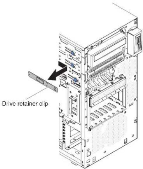
Figure34.Driveretainerclipinstallationfor5Uservermodelwithhot-swappowersupplies
- Pushthedriveintothebay.
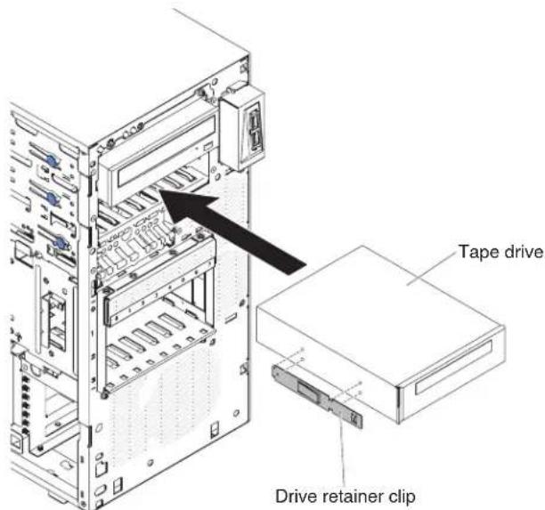
Figure35. Tapedrive installation for 5User model with hot-swappowersupplies
-
Connectoneendoftheapplicablesignalcableintotherearofthedriveand makesurethattheotherendofthiscableisconnectedintotheapplicable connectoronthesystemboard.
-
Routethesignalcablesothatitdoesnotblocktheairflowtotherearofthe drivesoroverthemicroprocessoranddualinlinememorymodules(DIMMs).
-
Connectthepowercabletotherearofthedrive.Theconnectorsarekeyed andcanbeinsertedonlyoneway.
Attention: If notapedrive is installed, it is important to install the filler back to the bay.
If you have other device to install, dosonow. Otherwise, goto "Completing the installation" on page 82.
Installingasimple-swapharddiskdrive
Thisprocedureappliesonlyto4Uservermodelswithnon-hot-swappower supplies.
The4Usermodelwithnon-hot-swappowersuppliessupportsuptofour 3.5-inchsimple-swapSATAharddiskdrives,whichareaccessiblefromthefrontof theserver.
Note: Only 3TBorbelowharddiskdriveoptionsaresupported by the 4Userver model with non-hot-swappowersupplies.
Youmustdisconnectallpowerfromtheserverbeforeyouremoveorinstall simple-swapdrives.Beforeyouinstallasimple-swapSATAharddiskdrive,read thefollowinginformation:
Installthedrivesstartingfromthetopbaytothebottombay(bay3,4,5,and then 6).ThefollowingtableslisttheIDsoftheharddiskdrives:
Table8.IDsofsimple-swapdrives
| DrivebayHDDID | |
| 3 | 0 |
| 4 | 1 |
| 5 | 2 |
| 6 | 3 |
- Thesimple-swapSATAharddiskdrivesconnecttotheSATA0throughSATA3 connectorsonthesystemboardasfollows:
- Systemboardendcableconnector0connectstotheSATA0connectoronthe systemboard.
- Systemboardendcableconnector1connectstotheSATA1connectoronthe systemboard.
- Systemboardendcableconnector2connectstotheSATA2connectoronthe systemboard.
- Systemboardendcableconnector3connectstotheSATA3connectoronthe systemboard.
•
-Harddiskdrive0connectstotheSATA0connectoronthesystemboard.
-Hardiskdrive1connectstotheSATA1connectoronthesystemboard.
-Harddiskdrive2connectstotheSATA2connectoronthesystemboard.
-Hardiskdrive3connectstotheSATA3connectoronthesystemboard.
Note: UnderRAIDmode:
- InuEFIsetupmenu:
-Drive0indicatesharddiskdrive0.
- Drive1indicatesharddiskdrive1.
- Drive2indicatesharddiskdrive2.
- Drive3indicatesharddiskdrive3.
- InMegaRAIDStorageManagerutility:
- Slot0indicatesharddiskdrive0.
- Slot1indicatesharddiskdrive1.
- Slot2indicatesharddiskdrive2.
- Slot3indicatesharddiskdrive3.
Attention: Simple-swapharddiskdrivesarenothot-swappable.Disconnectall powerfromtheserverbeforeyouremoveorinstallasimple-swapharddiskdrive
Note: If you installed a Serve RAID adapter in the server, connect the other end of the SATAsignal cable to the connector on the Serve RAID adapter.
Toinstallasimple-swapSATAharddiskdriveon4Uservermodelswith non-hot-swappowersupplies,completethefollowingsteps.
-
Readthesafetyinformationin"Safety"onpageviand"Installation guidelines"onpage35.
-
Turnoff the server and peripheral devices and disconnect all external cables and power cords.
-
Removethebezel(see"Removingthebezel"onpage40).
-
Touchthestatic-protectivepackagethatcontainsthedrivetoanyunpainted metalsurfaceontheserver;then,removethedrivefromthepackageandplaceitonastatic-protectivesurface.
-
Alignthedriveassemblywiththeguiderailsinthebay(theconnectorendof thedrivegoesinfirst).
-
Grasptheblackdrivehandleandslidethebluereleaselatchtotheright;then, carefullyslidethedriveassemblyintothedrivebayuntilitstops,andrelease thelatch.
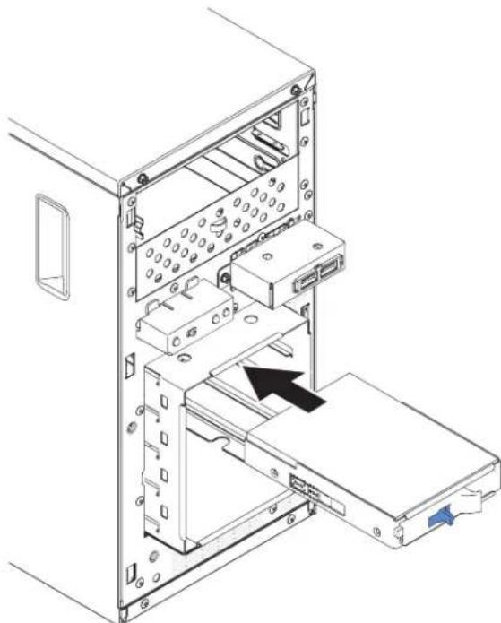
natural_image
Technical line drawing of a computer tower internal structure showing internal components and an arrow indicating a specific component (no text or symbols present)Figure36. Simple-swapharddiskdriveinstallationfor4Uservermodelwithnon-hot-swap powersupplies
If you have other device to install, do sonow. Otherwise, goto "Completing the installation" on page 82.
Installingahot-swapharddiskdrive
Thisprocedureappliesonlytothe5Uservermodelwithhot-swappowersupplies.
If you are replacing a drive, makes sure that:
•Thehot-swapdrivesmustbeeitherallSASharddiskdrivesorallSATAhard diskdrives;thetwotypescannotbecombined.
- Inspectthedrivetrayforsignsofdamage.
• Tomaintainpropersystemcooling, donotoperatetheserverformorethan10 minutes without at least one hard disk drive installed in the drive bay.
- Youdonothavetoturnofftheservertoinstallhot-swapdrivesinthehot-swap drivebays.
Toinstallahot-swapharddiskdriveonthe5Uservermodelthathavehot-swap powersupplies,completethefollowingsteps.
The following illustrations show the installation of a 2.5" hot swaphard disk into a 5User model with hot-swappowers supplies.

Figure37.2.5"hotswapharddiskdriveinstallationfor5Uservermodelwithhot-swappower supplies
The following illustrations show the installation of a 3.5" hot swaphard disk into a 5User model with hot-swappowers supplies.

Figure38.3.5"hotswapharddiskdriveinstallationfor5Uservermodelwithhot-swappower supplies
-
Readthesafetyinformationin"Safety"onpageviand"Installation guidelines"onpage35.
-
Touchthestatic-protectivepackagethatcontainsthedrivetoanyunpainted metalsurfaceontheserver;then,removethedrivefromthepackageandplaceitonastatic-protectivesurface.
- Makesurethatthedrivetrayhandleisintheopenposition.
- Alignthedriveassemblywiththeguiderailsinthebay;then,carefullyslide thedriveassemblyintothedrivebayuntilthedrivestops.
- Rotatethedrivetrayhandletotheclosedposition.
- Checktheharddiskdrivestatusindicatortomakesurethattheharddisk driveisoperatingcorrectly.(Youmighthavetorestarttheserverforthedrive toberecognized.)IftheyellowharddiskdrivestatusLEDforadriveislit continuously,itindicatesthatthedriveisfaultyandmustbereplaced.Ifthe greenharddiskdriveactivityLEDisflashing,thisindicatesthatthedriveis beingaccessed.
Note: If the server is configured for RAID operation using a Serve RAID controller, you might have to configure the disk arrays after you replace hard disk drives. See the Serve RAID documentation for additional information about RAID operation and complete instructions for using Serve RAID Manager.
If you have other device to install, dosonow. Otherwise, goto "Completing the installation" on page 82.
Installinganadapter
Usethisinformationtoinstallanadapter
Attention: When installing the Intel x520 Dual Port 10 Gb ESFP + adapter (option part number is 49 Y7960), the maximum number that can be installed in the server istwo.
Forthelocationsoftheexpansionslotsandconnectors,pleasesee"System-boardinternalconnectors"onpage30.
Toinstallareplacementadapteron4Uservermodelswithnon-hot-swappower supplies,completethefollowingsteps.Forthe5Uservermodelwithhot-swap powersupplies,pleaseseethenextsub-section.
- Readthesafetyinformationin"Safety"onpageviand"Installation guidelines"onpage35.
- Check the instruction that comewith the adapter for any requirements, restrictions, or cabling instructions. It might be easier to route cables before you install the adapter.
- Follow the instruction that comewith the adapter to set jumpers or switches, if any.
- Touchthestatic-protectivepackagethatcontainstheadaptertoanyunpainted metalsurfaceontheserver.Then,removtheadapterfromthe static-protectivepackage.Avoidtouchingthecomponentsandgold-edge connectorsontheadapter.
- Turnoff the server and all peripheral devices; then, disconnect the power cords and all external cables.
- Carefullyturntheserveronitssidesothatitislyingflat, with thecover facingup.
Attention: Donotallowtheserverterofallover.
-
Removethesidecover(see "Removingthesidecover" on page 38).
-
Removetheairbaffle(see"Removingtheairbaffle"onpage39).
- Followthecablinginstructions,ifany,thatcomewiththeadapter.Routethe adaptercablesbeforeyouinstalltheadapter.
- Follow the instruction that comewith the adapter to set jumpers or switches, if any.
- Lifttheendoftherearadapterretentionbrackettillthetabdisengagesthe holeonthechassis.
- Rotatetherearadapterretentionbracketupwardtoremoveitfromthe chassis.
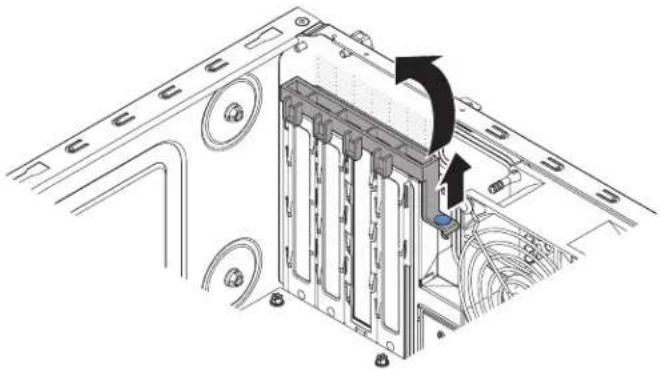
natural_image
Technical diagram of a computer motherboard showing internal components and a scroll wheel (no text or labels)Figure39. Rearadapterretentionbracketremovalfor4Uservermodelwithnon-hot-swap powersupplies
- Removetheexpansion-slotcoverbyunscrewingthescrewthatsecuresitto thechassis.Storetheexpansion-slotcoverandscrewinasafeplaceforfuture use.
Note: Expansion-slotcoversmustbeinstalledonallyvacantslots. This maintains the electronicemissions standard of the server and ensures proper ventilation of server components.
- Carefullygrasptheadapterbythetopedgeoruppercorners, and alignit with the expansions slot guides; then, press the adapter firmly into the expansions slot. Makes sure that the adapter is correctly seated in the expansion slot before you turn on the server. In complete installation of an adapter might damage the system board or the adapter.
Attention: Makesurethattheadapteriscorrectlyseatedintheexpansion slotbeforeyouturnontheserver.Incompleteinstallationofanadaptermight damagethesystemboardortheadapter.

Figure40. Adapterinstallationfor4Uservermodelwithnon-hot-swappowersupplies
- Positiontherearadapterretentionbracketsothattheholeinoneofthehinge pointsisalignedwiththehingepinonthechassis;then,placethehingepin throughtheholeonthechassis.

natural_image
Technical diagram of a computer motherboard showing internal components and a close-up inset of a pipe fitting (no text or symbols)Figure41. Rearadapterretentionbracketinstallationfor4Uservermodelwithnon-hot-swap powersupplies
-
Rotatetherearadapterretentionbracketintoplacesothattheholeinthe oppositehingepointsnapsintoplaceoverthehingepinonthechassis.
-
Connectanyrequiredcablestotheadapter.Routethecablessothattheydo notblocktheflowofairfromthesystemfan.
- Installtheairbaffle(see"Replacingtheairbaffle"onpage185).
If you have other device to install, do so now. Otherwise, goto "Completing the installation" on page 82.
Toinstallaanadapteronthe5Usermodelwithhot-swappowersupplies, completethefollowingsteps.For4Uservermodelswithnon-hot-swappower supplies.pleaseseetheabovesub-section.
- Readthesafetyinformationin"Safety"onpageviiand"Installation guidelines"onpage35.
- Check the instruction that comewith the adapter for any requirements, restrictions, or cabling instructions. It might be easier to route cables before you install the adapter.
- Follow the instruction that comewith the adapter to set jumpers or switches, if any.
- Touchthestatic-protectivepackagethatcontainstheadaptertoanyunpainted metalsurfaceontheserver.Then,removtheadapterfromthe static-protectivepackage.Avoidtouchingthecomponentsandgold-edge connectorsontheadapter.
- Turnoff the server and all peripheral devices; then, disconnect the power cords and all external cables.
- Unlockandremovethesidecover(see "Removingthesidecover" on page 38).
- Carefullyturntheserveronitssidesothatitislyingflat, with the system board facing up.
Attention: Donotallowtheservertofallover.
-
Rotatetherearadapter-retentionbrackettotheopen(unlocked)position.
-
Removetheexpansion-slotcoverbyunscrewingthescrewthatsecuresitto thechassis.Storetheexpansion-slotcoverandscrewinasafeplaceforfuture use.
Note: Expansion-slotcoversmustbeinstalledonallvacantslots. This maintains the electronic missions standards of the server and ensures proper ventilation of server components.
- Carefullygrasptheadapterbythetopedgeoruppercorner,andmovethe adapterdirectlyfromthestatic-protectivepackagetotheexpansionslot.Align theadapterwiththeexpansionslotguides;then,presstheadapterfirmlyinto theexpansionslot.
- Connecttherequiredcablestotheadapter.Routecablessothattheydonot blocktheairflowfromthefan.
- Positiontherearadapterretentionbracketsothattheholeinoneofthehinge pointsisalignedwiththehingepinonthechassis;then,placethehingepin throughtheholeonthechassis.

Figure42. Adapterinstallationfor5Usermodelwithhot-swappowersupplies
If you have other device to install, do onow. Otherwise, goto "Completing the installation" on page 82.
Installingamicroprocessorandheatsink
Usethisinformationtoinstallamicroprocessorandheatsink
Toinstallthemicroprocessorandheatsinkon4Uservermodelswith non-hot-swappowersupplies,completethefollowingsteps.Forthe5User modelwithhot-swappowersupplies,pleaseseethenextsub-section.
- Readthesafetyinformationin"Safety"onpageviand"Installation guidelines"onpage35.
- Turnoff the server and all attached devices; then, disconnect all power cords and external cables.
- Carefullyturntheserveronitssidesothatitislyingflat,withthecover facingup.
Attention: Donotallowtheservertofallover.
- Removethesidecover(see"Removingthesidecover"onpage38).
- Removetheairbaffle(see "Removingtheairbaffle" on page 39).
- Touchthestatic-protectivepackagethatcontainsthemicroprocessortoany unpaintedmetalsurfaceontheserver.Then,removethemicroprocessorfrom thepackage.
-
Removetheprotectivecover, tape, or labelfrom the surface of the microprocessor socket, if any is present.
-
Rotatethereleaseleveronthemicroprocessorsockettothefullyopen position.
Attention: Makesure that there lease cleveronthemicroprocessorsocket is in the fully open position before you insert them microprocessor in the socket. Failure todos might result in permanent damage to the microprocessor, microprocessor socket, and system board.
- Carefullygraspthemicroprocessorandplacethemicroprocessorintothe microprocessorsocket.
Note: Tomaintaincorrectorientationbetweenthemicroprocessorandthe microprocessorsocketduringinstallation,observethefollowinginformation:
- Themicroprocessorhastwonotchesthatarekeyedtotwotabsonthesides ofthesocket.
- A triangle-shaped indicator on one corner of the microprocessor point stoa 45-degree angle on the system board.
-
Donotuseexcessiveforcewhenyoupressthemicroprocessorintothe socket.
-
Closethemicroprocessorbracketframe;then,closethemicroprocessor retentionlatchandlockitsecurelyinplace.

Figure43. Microprocessorbracketframe and retentionlatchengagement for 4User models with non-hot-swappowersupplies
- Installtheheatsink:
Attention: Tomaintaincorrectorientationbetweenthemicroprocessorand themicroprocessorsocketduringinstallation,observethefollowing information:
a. Alignthescrewholesontheheatsinkwiththeholesonthesystemboard.
b. Tightenthescrewswithascrewdriver,alternatingamongthescrewsuntil theyaretight.Ifpossible,eachscrewshouldberotatedtwofullrotations atatime.Repeatuntilthescrewsaretight.Donotovertightenthescrews byusingexcessiveforce.
Important: Donottouchthethermalmaterialonthebottomoftheheat sink. Touchingthethermalmaterialwillcontaminateit. If the thermal materialonthemicroprocessororheatsinkbecomescontaminated, contact yourservicetechnician.

Figure44.Heatsinkinstallationfor4Uservermodelswithnon-hot-swappowersupplies
- Reconnectanycablesthatyoudisconnectedduringtheremovaloftheold microprocessor.
- SecuretheSATAsignalcableswiththeretention-clips.
- Installtheairbaffle(see"Replacingtheairbaffle"onpage185).
If you have other device to install, dosonow. Otherwise, goto "Completing the installation" on page 82.
Toinstall themicroprocessor and heatsinkon the 5User vermodel with hot-swap powersupplies, complet the following steps. For 4 User ver models with non-hot-swappowersupplies, please seethe abovesub-section.
- Readthesafetyinformationin"Safety"onpageviiand"Installation guidelines"onpage35.
- Turnoff the server and all attached devices; then, disconnect all power cords and external cables.
-
Unlockandremovethesidecover(see"Removingthesidecover" on page 38).
-
Carefullyturntheserveronitssidesothatitislyingflat,withthesystem boardfacingup.
Attention: Donotallowtheservertofallover.
-
Touchthestatic-protectivepackagethatcontainsthemicroprocessortoany unpaintedmetalsurfaceontheserver.Then,removethemicroprocessorfrom thepackage.
-
Removetheprotectivecover, tape, or labelfromthesurfaceofthe microprocessorsocket, if any is present.
-
Rotatethereleaseleveronthemicroprocessorsockettothefullyopen position.
Attention: Makesurethatthereleaseleveronthemicroprocessorsocketis inthefullyopenpositionbeforeyouinsertthemicroprocessorinthesocket. Failuretodosomightresultinpermanentdamagetothemicroprocessor, microprocessorsocket,andsystemboard.
- Carefullygraspthemicroprocessorandplacethemicroprocessorintothe microprocessorsocket.
Note: Tomaintaincorrectorientationbetweenthemicroprocessorandthe microprocessorsocketduringinstallation,observethefollowinginformation:
• Themicroprocessorhastwonotchesthatarekeyedtotwotabsonthesides ofthesocket.
- A triangle-shaped indicator on one corner of the microprocessor point stoa 45-degree angle on the system board.
- Donotuseexcessiveforcewhenyoupressthemicroprocessorintothe socket.
- Closethemicroprocessorbracketframe;then,closethemicroprocessor retentionlatchandlockitsecurelyinplace.

Figure45. Microprocessorbracketframeandretentionlatchengagementfor5Userver modelswithhot-swappowersupplies
- Installtheheatsink:
Attention: Tomaintaincorrectorientationbetweenthemicroprocessorand themicroprocessorsocketduringinstallation,observethefollowing information:
a. Alignthescrewholesontheheatsinkwiththeholesonthesystemboard.
b. Tightenthescrewswithascrewdriver,alternatingamongthescrewsuntil theyaretight.Ifpossible,eachscrewshouldberotatedtwofullrotations atatime.Repeatuntilthescrewsaretight.Donotovertightenthescrews byusingexcessiveforce.
Important: Donottouchthethermalmaterialonthebottomoftheheat sink. Touchingthethermalmaterialwillcontaminateit. If the thermal materialonthemicroprocessororheatsinkbecomescontaminated, contact yourservicetechnician.

Figure46.Heatsinkinstallationfor5Uservermodelswithhot-swappowersupplies
- Reconnectanycablesthatyoudisconnectedduringtheremovaloftheold microprocessor.
- Rotatetherearadapter-retentionbrackettotheclosed(locked)position.
If you have other device to install, dosonow. Otherwise, goto "Completing the installation" on page 82.
Thermalgrease
Thethermalgreasemustbereplacedwhenevertheheatsinkhasbeenremoved fromthetopofthemicroprocessorandisgoingtobereusedorwhendebrisis foundinthegrease.Usethisinformationoreplacedamagedorcontaminated thermalgreaseonthemicroprocessorandheatsink.
When you are installing the heatsinkonthesamemicroprocessorthatiswas removed from, makesure that the following requirements are met:
- Thethermalgreaseontheheatsinkandmicroprocessorisnotcontaminated.
• Additional thermal grease is not added to the existing thermal grease on the heatsink and microprocessor.
Notes:
- Readthesafetyinformationin"Safety"onpagevii.
- Readthe"Installationguidelines"onpage35.
- Read "Handlingstatic-sensitivedevices" on page 37.
Toreplacedamagedorcontaminatedthermalgreaseonthemicroprocessorand heatsink,completethefollowingsteps:
- Placetheheatsinkonacleanworksurface.
- Removethecleaningpadfromitspackageandunfolditcompletely.
- Usethecleaningpadtowipethethermalgreasefromthebottomoftheheat sink.
Note: Makesurethatallofthermalgreaseisremoved.
-
Useacleanareaofthecleaningpadtowipethethermalgreasefromthe microprocessor;then,disposeofthecleaningpadafterallofthermalgrease isremoved.
-
Use the thermal-greasesyringetoplace9uniformlyspaceddotsof0.02mL eachonthetopofthemicroprocessor. The outermostdotsmustbewithin approximately 5mmoftheedgeofthemicroprocessor; thisistoensure uniformdistributionofthegrease.
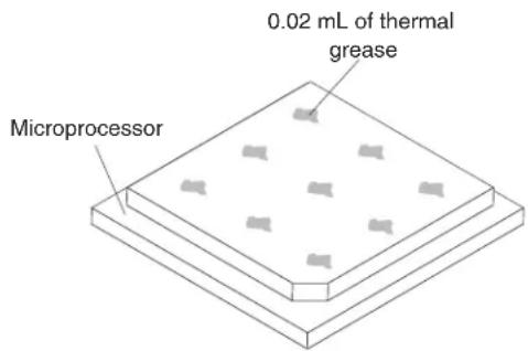
Figure47. Thermalgreasedistribution
Note: If the grease is properly applied, approximately half of the greas will remain in the syringe.

Figure48.Syringe
- Installtheheatsinkontothemicroprocessorasdescribedin"Replacing the microprocessorandheatsink"onpage304.
Installingthenon-hot-swappowersupply
Thisprocedureappliesonlyto4Uservermodelswithnon-hot-swappower supplies.
Statement8

CAUTION:
Neverremovethecoveronapowersupplyoranypartthathasthefollowing labelattached.

Hazardousvoltage,current,andenergylevelsarepresentinsideanycomponent thathasthislabelattached.Therearenoserviceablepartsinsidethese components.Ifyoususpectawithoneoftheseparts,contactaservice technician.
Toinstallanon-hot-swappowersupplyon4Uservermodelswithnon-hot-swap powersupplies,completethefollowingsteps.
-
Readthesafetyinformationin"Safety"onpageviand"Installation guidelines"onpage35.
-
Touchthestatic-protectivepackagethatcontainsthenon-hot-swappower supplytoanyunpaintedmetalsurfaceontheserver;then,removethepower supplyfromthepackageandplaceitonastatic-protectivesurface.
-
Turnoff the server and all attached devices; then, disconnect all power cords and external cables.
-
Carefullyturntheserveronitssidesothatitislyingflat,withthecoverfacing up. Attention:Donotallowtheserverterofallover.
-
Removethesidecover(see"Removingthesidecover"onpage38).
-
Removetheairbaffle(see"Removingtheairbaffle"onpage39).
-
Removethecatsink(see "Removingthemicroprocessorandheatsink" on page300).
-
Position the powers supply in the chassis so that the crew holes in the power supply are aligned with the corresponding holes in therear of the chassis.
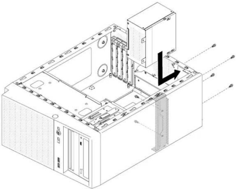
natural_image
Isometric technical diagram of a computer tower internal structure with no visible text or symbolsFigure49. Non-hot-swappowersupplyalignmentwithchassisfor4Uservermodelswith non-hot-swappowersupplies
Note: Makesurethetopandthebottomofthepowersupplyalignwiththe upperandlowertabsontheopening.

Figure50.Non-hot-swappowersupplyinstallationfor4Uservermodelswithnon-hot-swap powersupplies
- Installthescrewsthatsecurethepowersupplytothechassis.
If you have other device to install, dosonow. Otherwise, goto "Completing the installation" on page 82.
Installingthehot-swappowersupply
Thisprocedureappliesonlytothe5Uservermodelwithhot-swappowersupplies.
The following items describe the type of powersupply that the servers supports and other information that you must consider when you install powersupply:
•Toconfirmthattheserversupportsthepowersupplythatyouareinstalling,see http://www.ibm.com/systems/info/x86servers/serverproven/compat/us
- Theservercomesstandardwithone430-watthot-swappowersupply.Theinput voltageis110Vacor220Vacauto-sensing.
- Thesepowersuppliesaredesignedforparalleloperation.Intheeventofa power-supplyfailure,theredundantpowersupplycontinuestopowerthe system.Theserversupportsamaximumoftwopowersupplies.
- Theservercanrunfullyconfiguredwithonepowersupply.Forredundancy support,youmustinstallthesecondhot-swappowersupply.
Note: You cannot mix high-efficiency and non-high-efficiency powers supplies in the server.
Statement5

CAUTION:
The power control button on the device and the powers switch on the power supply don't turn off the electrical currents supplied to the device. The device also might have more than one power cord. Toremove all electrical current from the device, ensure that all power cords are disconnected from the powers source.

Statement8

CAUTION:
Neverremovethecoveronapowersupplyoranypartthathasthefollowing labelattached.

Hazardous voltage, current, and energy levels are present inside an component that has this label attached. There are no serviceable parts inside these components. If you suspect with one of these parts, contact a service technician.
Attention: During normal operation, each power-supply bay must contain either apowersupply or power-supply filler for proper cooling.
Toinstallahot-swappowersupplyonthe5Uservermodelwithhot-swappower supplies,completethefollowingsteps.
-
Readthesafetyinformationin"Safety"onpageviiand"Installation guidelines"onpage35.
-
Touchthestatic-protectivepackagethatcontainsthehot-swappowersupplyto anyunpaintedmetalsurfaceontheserver;then,removethepowersupply fromthepackageandplaceitonastatic-protectivesurface.
-
Placethepowersupplyintothebayguides.
-
Using the handle, push the powers supply toward the front of the chassis until it locks in to place.

Figure51. Hot-swappowersupplyinstallationfor5Uservermodelwithhot-swappower supplies
- Connectoneendofthepowercordintotheconnectoronthebackofthepower supplyandconnecttheotherendofthepowercordintoaproperlygrounded electricaloutlet.
- MakesurethatboththeacanddcpowerLEDsontherearofthepower supplyarelit, indicating that the powersupply is operating correctly.
If you have other device to install, do onow. Otherwise, goto "Completing the installation" on page 82.
Installingthethermalsolutionfankit
Usethisinformationtoinstallthethermalsolutionfankit
Attention:
- Toensurepropercoolingandairflow,donotoperatetheserverformorethan 30minuteswiththesidecoverremoved.
- When you install second adapter in the headapters slot on the system board, you must install the IBM Thermal Solution Fankit option to ensure proper cooling and airflow to the system. For 4 User models with non-hot-swaps powers supplies, the part number is 46 W9177. For 5 User models with hot-swaps powers supplies, the part number is 00 Y8200.
Toinstallthethermalsolutionfankiton4Uservermodelswithnon-hot-swap powersupplies,completethefollowingsteps.Forthe5Uservermodelwith hot-swappowersupplies,pleaseseethenextsub-section.
- Readthesafetyinformationin"Safety"onpageviiand"Installation guidelines"onpage35.
-
Turnoff the server and all attached devices; then, disconnect all power cords and external cables.
-
Carefullyturntheserveronitssidesothatitislyingflat,withthecoverfacing up.
Attention: Donotallowtheservertofallover.
-
Removethesidecover(see"Removingthesidecover"onpage38).
-
Removetheairbaffle(see"Removingtheairbaffle"onpage39).
-
Followanyspecialhandlingandinstallationinstructionsthatcomewiththe thermalsolutionfankit.
-
Insertthethermalsolutionfankit:
a. Graspthesystemfanbythebluepointandloweritintotheserver, making sureitlatchesontothechassis.
b. Connectthefancabletothesystemboard(see"System-boardinternal connectors"onpage30).

Figure52. Thermalsolutionfankitinstallationfor4Uservermodelwithnon-hot-swappower supplies
- If you have other device to install, do on now. Otherwise, goto "Completing the installation" on page 82.
Toinstallthethermalsolutionfankiton5Uservermodelswithhot-swappower supplies,completethefollowingsteps.Forthe4Uservermodelwithnon-hot-swappowersupplies,pleasesectheabovesub-section.
-
Readthesafetyinformationin"Safety"onpageviand"Installation guidelines"onpage35.
-
Turnoff the server and all attached devices; then, disconnect all power cords and external cables.
-
Unlockandremovethesidecover(see"Removingthesidecover" on page 38).
-
Carefullyturntheserveronitssidesothatitislyingflat,withthecoverfacing up.
Attention: Donotallowtheservertofallover.
- Insertthethermalsolutionfankit:
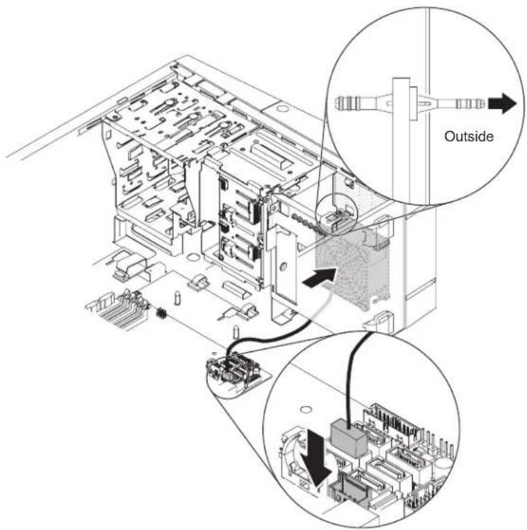
Figure53. Thermalsolutionfankitinstallationfor5Uservermodelwithhot-swappower supplies
a. Positionthefansothatthegrommetsprotrudethroughtheholesinthe chassis;then,useneedle-nosedplierstopullthegrommetsthroughthe holesfromoutsidethechassis.
b. Connectthefancableintothesystemboard(see"System-boardinternal connectors"onpage30).
- If you have other devices to install, do so now. Otherwise, goto "Completing the installation" on page 82.
Installingthebatteryholderinto5Uservermodel
Usethisinformationtoinstallthebatteryholderinto5Uservermodel
Attention: To ensure proper cooling and airflow, donotoperatetheserver for more than 30 minutes with the sidecover removed.
To install the battery holder into 5 User models with hot-swappowers supplies, complet the following steps.
-
Readthesafetyinformationin"Safety"onpageviiand"Installation guidelines"onpage35.
-
Turnoff the server and all attached devices; then, disconnect all power cords and external cables.
-
Unlockandremovethesidecover(see"Removingthesidecover" onpage38).
-
Carefully turn the server on its sides that it is lying flat, with the cover facing up.
Attention: Donotallowtheservertofallover.
- Insert the battery holder into the bracket.
Battery holder
Figure 54. Battery holder insertion into bracket for 5U server models with hot-swap power supplies
- Tighten the screw to secure the battery holder and bracket to the chassis.
Figure 55. Securing battery holder to chassis for 5U server models with hot-swap power supplies
- If you have other devices to install, do so now. Otherwise, go to "Completing the installation" on page 82.
Installingtheoperatingtemperatureenhancementkit
Usethisinformationtoinstalltheoperatingtemperatureenhancementkit
Attention: To ensure proper cooling and airflow, donotoperatetheserver for more than 30 minutes with theseidecover removed.
Toinstalltheoperatingtemperatureenhancementkiton4Uservermodelswith non-hot-swappowersupplies,completethefollowingsteps.Forthe5Userver modelwithhot-swappowersupplies,pleaseseethenextsub-section.
- Readthesafetyinformationin"Safety"onpageviiand"Installation guidelines"onpage35.
- Turnoff the server and all attached devices; then, disconnect all power cords and external cables.
- Removethebezel(see"Removingthebezel"onpage40).
- Carefully turn the server on its sides that it is lying flat, with the cover facing up.
Attention: Donotallowtheservertofallover.
- Removethesidecover(see"Removingthesidecover"onpage38).
- Insertthethermalsensorboardintothethermalsensorholder.Attachthe holderontotheserverandmakesurethecablinggoesthroughtheholeas shownintheillustration.

Figure56. Thermalsensorinstallationfor4Uservermodelswithnon-hot-swappower supplies
- Connectthethermalsensorconnectortothesystemboardandrememberto closethecableclipstosecurethecable.

Figure57. Installing thermalsensorconnectortosystemboard for 4Uservermodel with non-hot-swappowersupplies
- If you have other device to install, do onow. Otherwise, goto "Completing the installation" on page 82.
Toinstalltheoperatingtemperatureenhancementkiton5Uservermodelswith hot-swappowersupplies,completethefollowingsteps.Forthe4Uservermodel withnon-hot-swappowersupplies,pleaseseetheabovesub-section.
-
Readthesafetyinformationin"Safety"onpageviiand"Installation guidelines"onpage35.
-
Turnoff the server and all attached devices; then, disconnect all power cords and external cables.
-
Unlockandremovethesidecover(see"Removingthesidecover" on page 38).
-
Removethelowerbezel(see"Removingthelowerbezel"onpage42).
-
Removetheupperbezel(see"Removingtheupperbezel"onpage43).
-
Insertthethermalsensorboardintothethermalsensorholder.Attachthe holderontotheserverbyfittingitontothehook.Makesurethecablinggoes throughtherespectiveholesandcableclips,asshownintheillustration.

Figure58. Thermalsensorboardinstallationfor5Uservermodelwithhot-swappower supplies
-
Connectthethermalsensorconnectortothesystemboard.
-
If you have other device to install, do on now. Otherwise, goto "Completing the installation."
Completingtheinstallation
Usethisinformationtocompletetheinstallation.
Aboutthistask
Tocompletetheinstallation,completethefollowingsteps:
Procedure
- If you removed the air baffle, reinstall it (see "Replacing the bezel" on page 83).
- If you removed the airbaffle, reinstall it (see "Replacing the lower bezel" on page 84).
- If you removed the air baffle, reinstall it (see "Replacing the upper bezel" on page 84).
- If you removed the airbaffle, reinstall it (see "Replacing the airbaffle" on page 85).
- If you removed these sidecover, reinstall it (see "Replacing these sidecover" on page87).
- Reconnectthecablesandpowercords(see"Connectingthecables" on page 89).
- Updatetheserverconfiguration(see "Updatingtheserverconfiguration" on page91).
- Starttheserver.Confirmthatitstartscorrectlyandrecognizesthenewly installeddevices,andmakesurethatnoerrorLEDsarelit.
- (IBMBusinessPartnersonly) Complete the additional steps in "Instructions for IBMBusinessPartners" on page 28.
Replacingthebezel
Thisprocedureappliesonlyto4Uservermodelswithnon-hot-swappower supplies.
Toinstallthebezelon4Uservermodelswithnon-hot-swappowersupplies, completethefollowingsteps.
- Readthesafetyinformationin"Safety"onpageviiand"Installation guidelines"onpage35.
- Insertthethreetabsonthebezelintothecorrespondingholesinthefrontof theserver.
- Rotatethebezeltotheserveruntillockssecurelyintoplace.
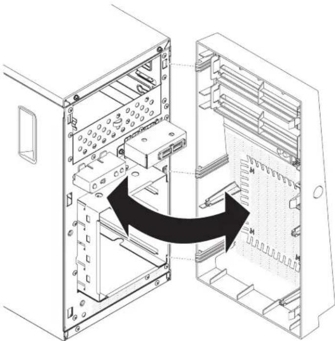
natural_image
Diagram of an internal server rack showing internal components and a black arrow indicating a directional flow (no text or symbols present)Figure59. Bezelinstallationfor4Uservermodelwithnon-hot-swappowersupplies
Replacingthelowerbezel
Thisprocedureappliesonlytothe5Uservermodelwithhot-swappowersupplies.
Toinstallthelowerbezelonthe5Uservermodelwithhot-swappowersupplies, completethefollowingsteps.
- Readthesafetyinformationin"Safety"onpageviiand"Installation guidelines"onpage35.
- Insertthetwobottomtabsonthelowerbezelintothecorrespondingholesin thefrontofthechassis.

natural_image
Diagram of a computer tower with an open storage unit and a closed panel, showing internal components and directional arrows (no text or symbols)Figure60. Lowerbezelinstallationfor5Uservermodelwithhot-swappowersupplies
- Rotatethetopofthelowerbezeluptothechassis;then,presstheblue-colored releasetabontherightsideofthelowerbezelandcompletelyclosethelower bezeluntilillockssecurelyintoplace.
Thisprocedureappliesonlytothe5Uservermodelwithhot-swappowersupplies.
Toinstalltheupperbezelonthe5Uservermodelwithhot-swappowersupplies, completethefollowingsteps.
- Readthesafetyinformationin"Safety"onpageviiand"Installation guidelines"onpage35.
- Insertthetwotabsontheright-sideoftheupperbezelintothecorresponding holesontherightsideofthechassis.
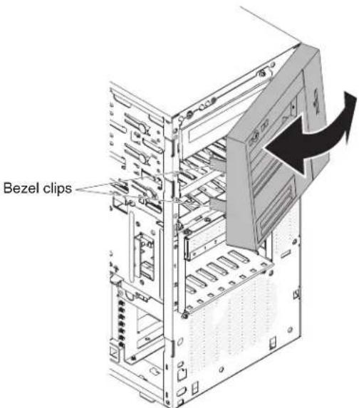
Figure61. Upperbezelinstallationfor5Uservermodelwithhot-swappowersupplies
- Rotatetheupperbezeltotheleftsideofthechassisuntilthebezelclipsare alignedwiththecorrespondingindentationsontheleftsideofthechassisand snapthemintoplace.
Replacingtheairbaffle
Thisprocedureappliesonlyto4Uservermodelswithnon-hot-swappower supplies.
Toinstalltheairbaffleinto4Uservermodelswithnon-hot-swappowersupplies, completethefollowingsteps.
-
Readthesafetyinformationin"Safety"onpageviiand"Installation guidelines"onpage35.
-
Alignthetabsontheairbafflewiththeslotsonthechassis.
-
Lowertheairbaffleintotheserver.
Attention:
- Makenoteofthemicroprocessorpowercablerouting, asthecablemay interferewith the airbaffle installation.

Figure62. Microprocessorpowercableroutingwheninstallingairbafflefor4Uservermodel withnon-hot-swappowersupplies
- Makesurethatthetabsontheairbaffleareinsertedintotheholesonthe chassisandnocablesarenotcaughtorpinched.
- Forpropercoolingandairflow,reinstalltheairbafflebeforeyouturnonthe server.Operatingtheserverwiththeairbaffleremovedmightdamageserver components.
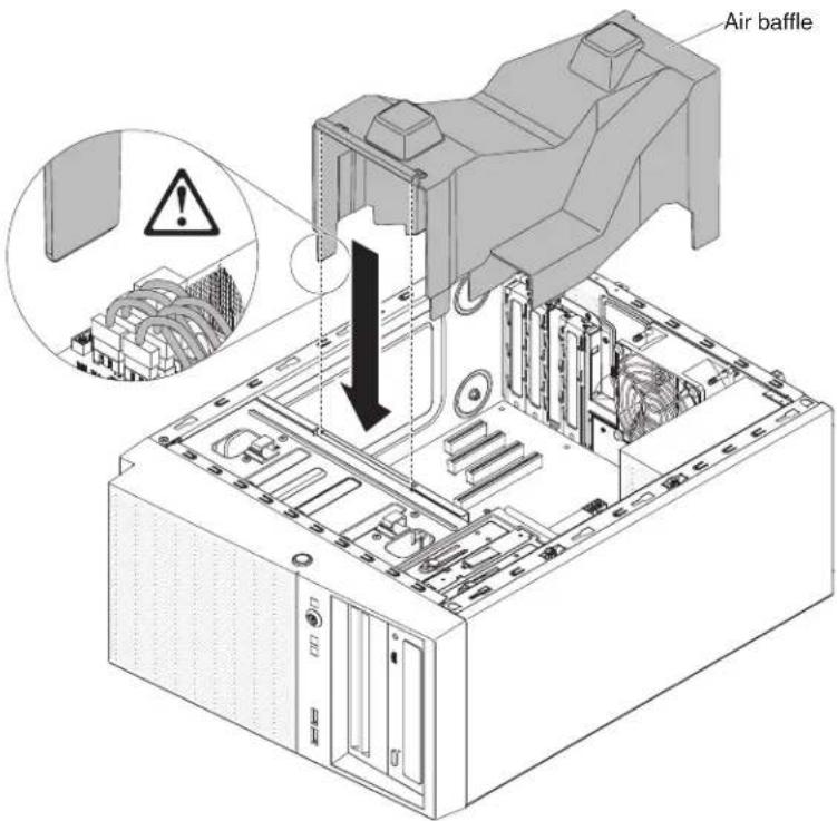
Figure63.Airbaffleinstallationfor4Uservermodelwithnon-hot-swappowersupplies
Replacingthesidecover
Usethisinformationoreplacethesidecover.
Attention: For proper cooling and airflow, replacethesidecover before returning on the server. Operating the server forextended period so time (more than 30 minutes) with the sidecover removed might damage server components.
For4Uservermodelswithnon-hot-swappowersupplies,completethefollowing stepstoremovethesidecover.Forthe5Uservermodelwithhot-swappower supplies,pleaseseethenextsub-section.
- Readthesafetyinformationin"Safety"onpageviiand"Installation guidelines"onpage35.
- Makesurethatallcables, adapters, and other components are installed and seated correctly and that you havenot left loose tools or parts inside the server. Also, makesure that all internal cables are correctly routed.
- Carefullyturntheserveronitssidesothatitislyingflat,withthecoverfacing up.
Attention: Donotallowtheserverterofallover. - Pressonthesidecoverandpushfromtherearsideofthesidecoveruntil lockssecurelyintoplace.

natural_image
Illustration of a computer tower case with two downward arrows indicating compression or disassembly (no text or symbols present)Figure64.Sidecoverinstallationfor4Uservermodelwithnon-hot-swappowersupplies
- Securethesidecoverinplacewiththetwochassisscrewsontherearofthe sidecover.
Forthe5Usermodelwithhot-swappowersupplies,completethefollowing stepsinordertoremovethesidecover.For4Usermodelswithnon-hot-swap powersupplies,pleaseseetheabovesub-section.
Attention: Thecoverlockmustbeintheunlocked(opened)positionbeforeyou installthesidecover.
-
Readthesafetyinformationin"Safety"onpageviand"Installation guidelines"onpage35.
-
Makesurethatallcables, adapters, and other components are installed and seated correctly and that you haven o left loose tools or parts inside the server. Also, makesure that all internal cables are correctly routed.
-
If you removed the upper and lower bezels, reinstall them before you replace the sidecover (see "Replacing the lower bezel" on page 190 and "Replacing the upper bezel" on page 192).
-
Positionthelipatthebottomedgeofthesidecoverontheledgeatthebottom ofthechassis;then,rotatethecoveruptothechassis.Pressdownonthecover releaselatchandpushthecoverintothechassisuntilitlatchessecurelyinto place.

Figure65.Sidecoverinstallationfor5Uservermodelwithhot-swappowersupplies
5. Lockthesidecover.
Connectingthecables
Usethisinformationtoconnectthecables.
Attention: Topreventdamagetoequipment, connectthepowercordslast.
If the server cables and connector panel have color-coded connections, match the color of the cable end with the color of the connector. Forexample, match a blue cable end with a blue panel connector, are cable end with a red connector, and so on.
The following illustrations show the input/output(I/O) connector on therear of therear of 4User models with non-hot-swappowersupplies.
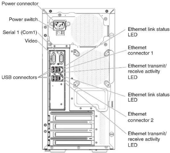
Figure66.Input/output(I/O)connectorsontherearof4Uservermodelswithnon-hot-swap powersupplies

Figure67.Input/output(I/O)connectorsontherearof5Uservermodelswithhot-swappower supplies
Updatingtheserverconfiguration
Usethisinformationtoupdatetheserverconfiguration.
When you start the server for the first time after you add or remove a device, you might receive a message that the configuration has changed. The Setup utility starts automatically so that you can save thenew configurations settings.
Someoptionaldeviceshavedevicedriversthatyoumustinstall.Forinformation aboutinstallingdevicedrivers,seethedocumentationthatcomeswitheachdevice.
If the server has an optional RAID adapter and you have installed or removed a hard disk drive, seethedocumentation that comes with the RAID adapter for information about reconfiguring the disk arrays.
ForinformationaboutconfiguringtheintegratedGigabitEthernetcontroller,see "ConfiguringtheGigabitEthernetcontroller" onpage110.
Connectingexternaldevices
Usethisinformationtoconnectexternaldevices
If you install as supported optional adapter, you can attach external device to the server.
Toattachanexternaldevice, completethefollowingsteps:
-
Readthesafetyinformationin"Safety"onpageviiand"Installation guidelines"onpage35.
-
Turnofftheserverandallattacheddevices.
-
Follow the instruction that comewith the device to prepare it for installation and to connect it to the server.
Note: If you are attaching an external device, seethedocumentation that comes with the device for information about cabling.
Installingtheserverinarack
Usethisinformationtoinstalltheserverinarack
Toconverttheserverfromatowermodeltoarackmodel,youmustusea Tower-to-RackKit.Youcantheninstalltheserverinarackcabinet.Toordera Tower-to-RackKitfortheserver,contactyourIBMmarketingrepresentativeor authorizedreseller.
Note:
- It is not necessary to remove the following items from the tower when installing the systemarack cabinet.
•Frontbezel
•DVD-ROMdrive
•Tapedrive
•FrontUSBconnectorassembly
•Operatorinformationpanelassembly
- Afterinstallingthesysteminarackcabinet,thedistancebetweentheEIA bracketandlowerbezelwillberoughly67mm.Inlightofthisdistance,please makesureyourrackcabinetdoorcanfullyclosebeforeyoubegintoinstallthe systemintherackcabinet.
Chapter3.Configurationinformationandinstructions
Thischapterprovidesinformationaboutupdatingthefirmwareandusingthe configurationutilities.
Updatingthefirmware
Use this information to update the system firmware.
Important:
- Someclustersolutionsrequiresspecificcodelevelsorcoordinatedcodeupdates. Ifthedeviceispartofaclustersolution,verifythatthelatestlevelofcodeis supportedfortheclustersolutionbeforeyouupdatethecode.
- Beforeyouupdatethefirmware,besuretobackupanydatathatisstoredin theTrustedPlatformModule(TPM),incaseanyoftheTPMcharacteristicsare changedbythenewfirmware.Forinstructions,seeyourencryptionsoftware documentation.
- Installingthewrongfirmwareordevice-driverupdatemightcausetheserver tomalfunction.Beforeyouinstallafirmwareordevice-driverupdate,readany readmeandchangehistoryfilesthatareprovidedwiththedownloaded update.Thesefilescontainimportantinformationabouttheupdateandthe procedureforinstallingtheupdate,includinganyspecialprocedurefor updatingfromanearlyfirmwareordevice-driverversiontothelatestversion.
You can install code updates that are packaged as an UpdateXpress System Pack or UpdateXpressCDimage.AnUpdateXpressSystemPackcontainsan integration-testedbundleofonlinefirmwareanddevice-driverupdatesforyour server. Use UpdateXpress System Pack Installer to acquire and apply UpdateXpress SystemPacksandindividualfirmwareanddevice-driverupdates.Foradditional informationandtodownloadtheUpdateXpressSystemPackInstaller,gotothe ToolsCenterforSystemxandBladeCenterathttp://www.ibm.com/support/entry/portal/docdisplay?Indocid=TOOL-CENTERandclickUpdateXpressSystem PackInstaller.
When you click an update, an information page is displayed, including a list of the problem that the update fixes. Review this list for your specific problem; however, even if your problem is not listed, installing the update might solve the problem.
Besuretoseparatelyinstallanylistedcriticalupdatesthathavereleasedatesthat are later than the release date of the UpdateXpress System Pack or UpdateXpress image.
The firmware fortheserverisperiodically updated and is available for download on the IBM website. To check forthelatest level off firmware, such as the UEFI firmware, devicedrivers, and integrated management module (IMM) firmware, go to http://www.ibm.com/support/fixcentral
Download the latest firmware for the server; then, install the firmware, using the instruction that are included with the downloaded files.
When you replace device in the server, you might have updated the firmware that is stored in memory on the device or restore the pre-existing firmware from a CD or DVD image.
The following list indicates where the firmware is stored:
•UEFIfirmwareisstoredinROMonthesystemboard.
- IMM2firmwareisstoredinROMonthesystemboard.
- EthernetfirmwareisstoredinROMontheEthernetcontrollerandonthe systemboard.
- ServeRAIDfirmwareisstoredinROMonthesystemboardandtheRAID adapter(ifoneisinstalled).
- SAS/SATAfirmwareisstoredinROMontheSAS/SATAcontrolleronthe systemboard.
Configuringtheserver
The following configuration programs comewith the server:
- Setuputility
TheSetuputilityispartoftheUEFIfirmware.Useittoperformconfiguration taskssuchaschanginginterruptrequest(IRQ)settings,changingthe startup-devicesequence,settingthedateandtime,andsettingpasswords.For informationaboutusingthisprogram,see"UsingtheSetuputility"onpage98.
- BootManagerprogram
TheBootManagerispartoftheUEFIfirmware.Useittooverridetheststartup sequence that i ssetin the Setuputility and temporarily assignadevicetobe firstinthestartupsequence. Formoreinformationaboutusing this program, see "UsingtheBootManager" on page 104.
• IBMServerGuideSetupandInstallationCD
TheServerGuideprogramprovidesoftware-setuptoolsandinstallationtools thataredesignedfortheserver. Use this CD during the installation of the server to configure basic hardware features, such as an integrated SAS/SATA controller with RAID capabilities, and to simplify the installation of your operating system. For information about using this CD, see "Using the Server Guide Setup and Installation CD" on page 96.
•Integratedmanagementmodule
Use the integrated management module II (IMM2) for configuration, to update the firmware and sensor data record / field replaceable unit (SDR/FRU) data, and to remotely manage an network. For information about using the IMM, see "Using the Integrated Management Module II (IMM2)" on page 105 and the Integrated Management Module II User's Guide at http://www-947.ibm.com/support/entry/portal/docdisplay?lndocid=migr-5086346.
- Remotepresencecapabilityandblue-screencapture
Theremotepresenceandblue-screencapturefeaturesareintegratedfunctionsof theintegratedmanagementmodule(IMM2).Theremotepresencefeature providesthefollowingfunctions:
- Remotelyviewingvideowithgraphicsresolutionupto1600x1200at75Hz, regardlessofthesystemstate
- Remotely accessing the server, using the keyboard and mouse from a remote client
-MappingtheCDorDVDdrive,diskettedrive,andUSBflashdriveona remoteclient,andmappingISOanddisketteimagefilesasvirtualdrivesthat areavailableforusebytheserver
-UploadingadisketteimagetotheIMMmemoryandmappingittotheserver asavirtualdrive
Theblue-screencapturefeaturecapturesthevideodisplaycontentsbeforethe IMMrestartstheserverwhentheIMMdetectsanoperating-systemhang condition. Asystemadministratorcanusetheblue-screencapturefeatureto assistindeterminingthecauseofthehangcondition. Formoreinformation, see "Usingtheremotepresenceandblue-screencapturefeatures" onpage106.
•Ethernetcontrollerconfiguration
ForinformationaboutconfiguringtheEthernetcontroller,see"Configuringthe GigabitEthernetcontroller"onpage110.
•FeaturesonDemandsoftwareEthernetsoftware
TheserverprovidesFeaturesonDemandsoftwareEthernetsupport.Youcan purchaseaFeaturesonDemandsoftwareupgradekeyforFibreChannelover Ethernet(FCoE)andiSCSIsstorageprotocols.Formoreinformation,see "EnablingFeaturesonDemandEthernetsoftware"onpage110.
•FeaturesonDemandsoftwareRAIDsoftware
The server provides Features on Demand software RAID support. You can purchase a Features on Demand software upgrade key for RAID. Form more information, see "Enabling Features on Demand RAID software" on page 111.
•IBMAdvancedSettingsUtility(ASU)program
Use this program as an alternative the Setup utility form modifying UEFI settings and IMM settings. Use the ASU program online or out of band to modify UEFI settings from the command line without the needed to restart the server tor on the Setup utility. Form more information about using this program, see "IBM Advanced Settings Utility program" on page 111.
- ConfiguringRAIDarrays
ForinformationaboutconfiguringRAIDarrays,see"ConfiguringRAIDarrays" onpage111.
The following table lists the different server configurations and the applications that are available for configuring and managing RAID arrays.
Table9.ServerconfigurationandapplicationsforconfiguringandmanagingRAIDarrays
| Serverconfiguration | RAIDarrayconfiguration (beforeoperatingsystemis installed) | RAIDarraymanagement (afteroperatingsystemis installed) |
| ServeRAID-M1115adapterMega | RAIDBIOSConfigurationUtility(press Ctrl+Htostart),pre-bootCLI (pressCtrl+Ptostart), ServerGuide,HII | MegaRAIDStorageManager (MSM),MegaCLI(Command LineInterface),andIBM Director |
| ServeRAID-M5110adapterMega | RAIDBIOSConfigurationUtility(press Ctrl+Htostart),pre-bootCLI (pressCtrl+Ptostart), ServerGuide,HII | MegaRAIDStorageManager (MSM),MegaCLI,andIBM Director |
| ServeRAID-M5120adapterMega | aRAIDBIOSConfigurationUtility(press Ctrl+Htostart),pre-bootCLI (pressCtrl+Ptostart), ServerGuide,HII | MegaRAIDStorageManager (MSM),MegaCLI,andIBM Director |
Notes:
- FormoreinformationabouttheHumanInterfaceInfrastructure(HII)and SAS2IRCU,gotohttp://www.ibm.com/support/entry/portal/docdisplay?Indocid=MIGR-5088601.
- FormoreinformationabouttheMegaRAID, gotohttp://www.ibm.com/support/entry/portal/docdisplay?Indocid=MIGR-5073015.
UsingtheServerGuideSetupandInstallationCD
Use this information as an overview for using the Server Guide Setup and Installation CD.
TheServerGuideSetupandInstallationCDprovidesoftwaresetuptoolsand installationtoolsthataredesignedforyourserver.TheServerGuideprogram detectstheservermodelandoptionalhardwaredevicesthatareinstalledanduses thatinformationduringsetuptoconfigurethehardware.TheServerGuide simplifiestheoperating-systeminstallationsbyprovidingupdateddevicedrivers and,insomecases,installingthemautomatically.
YoucandownloadafreeimageoftheServerGuideSetupandInstallationCDfrom http://www.ibm.com/support/entry/portal/docdisplay?Indocid=SERV-GUIDE
InadditiontotheServerGuideSetupandInstallationCD,youmusthaveyour operating-systemCDtoinstalltheoperatingsystem.
ServerGuidefeatures
ThisinformationprovidesanoverviewoftheServerGuidefeatures.
FeaturesandfunctionscanvaryslightlywithdifferentversionsoftheServerGuide program.Tolearnmoreabouttheversionthatyouhave,starttheServerGuideSetup andInstallationCDandviewtheonlineoverview.Notallfeaturesaresupportedon allservermodels.
TheServerGuideprogramhasthefollowingfeatures:
•Aneasy-to-useinterface
- Diskette-freesetup, and configurationprogramsthatarebasedondetected hardware
•Devidedriversthatareprovidedfortheservermodelanddetectedhardware
- Operating-systempartitionsizeandfile-systemtypethatareselectableduring setup
TheServerGuideprogramperformsthefollowingtasks:
- Setssystemdateandtime
- Detectsinstalledhardwareoptionsandprovidesupdateddevicedriversformostadaptersanddevices
- Providesdiskette-freeinstallationforsupportedWindowsoperatingsystems
- Includesanonlinereadmefilewithlinkstotipsforyourhardwareand operating-systeminstallation
Setupandconfigurationoverview
UsethisinformationfortheServerGuidesetupandconfiguration.
WhenyouusetheServerGuideSetupandInstallationCD,youdonotneedsetup diskettes.YoucanusetheCDtoconfigureanysupportedIBMservermodel.The setupprogramprovidesalistoftasksthatarerequiredtosetupyourserver model.OnaserverwithaServeRAIDadapterorSAS/SATAcontrollerwithRAID capabilities,youcanruntheSAS/SATARAIDconfigurationprogramtocreate logicaldrives.
Note: Features and functions can vary slightly with different versions of the ServerGuideprogram.
Typicaloperating-systeminstallation
ThissectiondetailstheServerGuidetypicaloperating-systeminstallation.
TheServerGuideprogramcanreducethetimeittakestoinstallanoperating system.Itprovidesthedevidedriversthatarerequiredforyourhardwareandfor theoperatingsystemthatyouareinstalling.Thissectiondescribesatypical ServerGuideoperating-systeminstallation.
Note: Features and functions can vary slightly with different versions of the ServerGuideprogram.
- After you have completed the setup process, the operating-system installation program starts. (You will need your operating-system CD to complete the installation.)
- TheServerGuideprogramstoresinformationabouttheservermodel,service processor,harddiskdrivecontrollers,andnetworkadapters.Then,the programcheckstheCDfornewerdevicedrivers.Thisinformationisstored andthenpassedtotheoperating-systeminstallationprogram.
- TheServerGuideprogrampresentsoperating-systempartitionoptionsthatare basedonyouroperating-systemselectionandtheinstalledharddiskdrives.
- TheServerGuideprogram prompts youtoinsert youroperating-systemCD and restart the server. At this point, the installation program for the operating system takes control to complete the installation.
Installing your operating system without using Server Guide
Usethisinformationtoinstalltheoperatingsystemontheserverwithoutusing ServerGuide.
If you have already configured the server hardware and you are not using the Server Guide program to install your operating system, you can download operating system installation instructions for the server from http://www.ibm.com/supportporta.
UsingtheSetuputility
UsetheseinstructionstostarttheSetuputility.
Use the Unified Extensible Firmware Interface (UEFI) Setup Utility program to perform the following tasks:
•Viewconfigurationinformation
•ViewandchangeassignmentsfordevicesandI/Oports
- Setthedateandtime
- Setandchangepasswords
- Setthestartupcharacteristicsoftheserverandtheorderofstartupdevices
- Setandchangesettingsforadvancedhardwarefeatures
•View,set,andchangesettingsforpower-managementfeatures
•Viewandclearerrorlogs
- Changeinterruptrequest(IRQ Cuba)settings
- Resolveconfigurationconflicts
StartingtheSetuputility
UsethisinformationtostartuptheSetuputility.
Aboutthistask
TostarttheSetuputility, completethefollowingsteps:
Procedure
- Turnontheserver.
Note: Approximately 5 to 10 seconds after the server is connected top power, the power-control button becomes active.
-
When the prompt
Setup is displayed, press F1. If you have set an administratorpassword,youmustypetheadministratorpasswordtoaccess thefullSetuputilitymenu.Ifyoudonottypetheadministratorpassword,a limitedSetuputilitymenuisavailable. -
Selectsettingstovieworchange.
Setuputilitymenuchoices
Use the Setup utility main menu to view and configureserver configuration data and settings.
The following choices are on the Setup utility main menu for the UEFI. Depending on the version of the firmware, some menu choices might differ slightly from these descriptions.
•SystemInformation
Selectthischoicetoviewinformationabouttheserver.WhenyoumakechangesthroughotherchoicesintheSetuputility, someofthosechangesarereflectedinthesysteminformation; youcannotchangesettingsdirectlyinthesysteminformation. ThischoiceisonthefullSetuputilitymenuonly.
-SystemSummary
Selectthischoicetoviewconfigurationinformation,includingtheID,speed,andcachesizeofthemicroprocessors,machinetypeandmodeloftheserver,theserialnumber,thesystemUUID,andtheamountofinstalledmemory.WhenyoumakeconfigurationchangesthroughotheroptionsintheSetuputility,thechangesarereflectedinthesystemsummary;youcannotchangesettingsdirectlyinthesystemsummary.
-ProductData
Select this choicetoview the system-boardidentifier, therevision level or issued at the firmware, the integrated management module and diagnosticscode, and the version and date.
ThischoiceisonthefullSetuputilitymenuonly.
- SystemSettings
Selectthischoicetovieworchangetheservercomponentsettings.
-AdaptersandUEFIDrivers
Select this choicetoviewinformationabouttheUEFI1.10andUEFI2.0 compliant adapters and drivers installed in the server.
-Processors
Selectthischoicetovieworchangetheprocessorsettings.
-Memory
Selectthischoicetovieworchangethememorysettings.
-DevicesandI/OPorts
Selectthischoicetovieworchangeassignmentsfordevicesand input/output(I/O)ports.Youcanconfiguretheserialports,configureremote consoleredirection,enableordisableintegratedEthernetcontrollers,the SAS/SATAcontrollers,SATAopticaldrivechannels,PCIslots,andvideo controller.Ifyoudisableadevice,itcannotbeconfigured,andtheoperating systemwillnotbeabletodetectit(thisisequivalenttodisconnectingthe device).
-Power
Select this choice to view or change powerercapping to control consumption, processors, and performance states.
-OperatingModes
Select this choice to view or change the operating profile (performance and power utilization).
-LegacySupport
Selectthischoicetovieworsetlegacysupport.
Select this choice to force INT video support, if the operating system does not support UEFI video output standards.
-RehookINT19h
Select this choiceto enable or disable devices from taking control of the bootprocess. The default is Disable.
-LegacyThunkSupport
SelectthischoicetoenableordisableUEFItointeractwithPCImass storagedevicesthatarenon-UEFIcompliant. ThedefaultisEnable.
-InfiniteBootRetry
SelectthischoicetoenableordisableUEFItoinfinitelyretrythelegacybootorder. ThedefaultisDisable.
-BBSBoot
SelectthischoicetoenableordisablelegacybootinBBSmanner. The defaultisEnable.
-SystemSecurity
SelectthischoicetovieworconfigureTrustedPlatformModule(TPM) support.
-IntegratedManagementModule
Select this choicetovieworchangethesettingsfortheintegrated managementmodule.
-PowerRestorePolicy
Selectthischoicetosethemodeofoperationafterthepowerlost.
-CommandsonUSBInterface
SelectthischoicetoenableordisabletheEthernetoverUSBinterfaceon IMM. ThedefaultisEnable.
-NetworkConfiguration
Selectthischoicetoviewthesystemmanagementnetworkinterfaceport, theIMMMACaddress, thecurrentIMMIPaddress, andhostname; define thestaticIMMIPaddress, subnetmask, andgatewayaddress, specify whetherousethestaticIPaddressorhaveDHCPassigntheIMM2IP address, savethenetworkchanges, andresettheIMM.
-ResetIMMtoDefaults
SelectthischoicetovieworresetIMMtothedefaultsettings.
-ResetIMM
Selectthischoicetovieworchangethestoragedevicesettings.
-Network
Selectthischoicetovieworchangethenetworkdeviceoptions,suchas iSCSI.
-DriveHealth
Selectthischoicetoviewthestatusofthecontrollersinstalledintheblade server.
- DateandTime
Selectthischoicetosethedateandtimeintheserver,in24-hourformat (hour:minute:second).
ThischoiceisonthefullSetuputilitymenuonly.
- StartOptions
Selectthischoicetovieworchangethestartoptions,includingthestartup sequence,keyboardNumLockstate,PXEbootoption,andPCIdeviceboot priority.Changesinthestartupoptionstakeeffectwhenyoustarttheserver.
The startup sequences specifiesthe orderin which the server checks device to find a boot record. The server starts from the first boot record that it finds. If the server has Wakeon LAN hardware and software and the operating system supports Wakeon LAN functions, you can specify a startup sequence for the Wakeon LAN functions. For example, you can define a startup sequence that checks for ad disc in the CD-RW/DVD drive, then check the hard disk drive, and then checks an network adapter.
ThischoiceisonthefullSetuputilitymenuonly.
- BootManager
Selectthischoicetoview,add,delete,orchangethedevicebootpriority,boot fromafile,selectaone-timeboot,orresetthebootordertothedefaultsetting.
- SystemEventLogs
SelectthischoicetoentertheSystemEventManager,whereyoucanviewthePOSTeventlogandthesystem-eventlog.Youcanusethearrowkeystomove betweenpagesintheerrorlog.ThischoiceisonthefullSetuputilitymenuonly.
ThePOSTeventlogcontainsthemostrecenterrorcodesandmessagesthat weregeneratedduringPOST.
Thesystem-eventlogcontainsPOSTandsystemmanagementinterrupt(SMI) eventsandalleventsthataregeneratedbythebaseboardmanagement controllerthatisembeddedintheintegratedmanagementmodule(IMM).
Important: If the system-error LED on the front of the server is lit but there are no other error indications, clear the system-event log. Also, after you complete a repair or correct an error, clear the system-event log to turn off the system-error LED on the front of the server.
-POSTEventViewer
SelectthischoicetoenterthePOSTeventviewertoviewthePOSTerror messages.
-SystemEventLog
Selectthischoicetoviewthesystemeventlog.
-ClearSystemEventLog
Selectthischoicetoclearthesystemeventlog.
-UserSecurity
Selectthischoicetoset,change,orclearpasswords.See"Passwords"onpage 103formoreinformation.
ThischoiceisonthefullandlimitedSetuputilitymenu.
-SetPower-onPassword
Selectthischoicetosetorchangepower-onpassword.See"Power-on password"onpage103formoreinformation.
-ClearPower-onPassword
Selectthischoicetoclearapower-onpassword.See"Power-onpassword"on page103formoreinformation.
-SetAdministratorPassword
Selectthischoicetosetorchangeanadministratorpassword.An administratorpasswordisintendedtobeusedbyasystemadministrator;it limitsaccesstothefullSetuputilitymenu.Ifanadministratorpasswordis set,thefullSetuputilitymenuisavailableonlyifyoutypetheadministrator passwordatthepasswordprompt.See"Administratorpassword"onpage [104]formoreinformation.
-ClearAdministratorPassword
Selectthischoicetoclearanadministratorpassword.See"Administrator password"onpage104formoreinformation.
- SaveSettings
Selectthischoicetosavethechangesthatyouhavemadeinthesettings.
-RestoreSettings
Select this choicetocancel the changest hat you havemade in these settings and restore the previous settings.
- LoadDefaultSettings
Select this choice to cancel the change that you have made in these settings and restore the factory settings.
- ExitSetup
SelectthischoicetoexitfromtheSetuputility.Ifyouhavenotsavedthe changesthatyouhavemadeinthesettings,youareaskedwhetheryouwantto savethechangesorexitwithoutsavingthem.
Passwords
From the User Security menu choice, you can set, change, and delete a power-on password and an administrator password.
TheUserSecuritymenuchoiceisonthefullSetuputilitymenuonly.
Ifyousetonlyapower-onpassword,youmusttypethepower-onpasswordto completethesystemstartupandtohaveaccesstothefullSetuputilitymenu.
Anadministratorpassworddisintendedtobeusedbyasystemadministrator;it limitsaccesstothefullSetuputilitymenu.Ifyousetonlyanadministrator password,youdonothavetotypeapasswordtocompletethesystemstartup,but youmusttypetheadministratorpasswordtoaccesstheSetuputilitymenu.
Ifyousetapower-onpasswordforauserandanadministratorpasswordforasystemadministrator,youmusttypethepower-onpasswordtocompletethesystemstartup.AsystemadministratorwhotypestheadministratorpasswordhasaccesstothefullSetuputilitymenu;thesystemadministratorcangivetheuserauthoritytoset,change,anddeletethepower-onpassword.Auserwhotypesthepower-onpasswordhasaccesstonlythelimitedSetuputilitymenu;theusercanset,change,anddeletethepower-onpassword,ifthesystemadministratorhasgiventheuserthatauthority.
Power-onpassword:
Ifapower-onpasswordisset,whenyouturnontheserver,youmusttypethe power-onpasswordtocompletethesystemstartup.Youcanuseanycombination of 6 - 2 0 printableASCIIcharactersforthepassword.
Whenapower-onpasswordisset,youcanenabletheUnattendedStartmode,in whichthekeyboardandmouseremainlockedbuttheoperatingsystemcanstart. Youcanunlockthekeyboardandmousebytypingthepower-onpassword.
If you forget the power-on password, you can regain access to the server in any of the following ways:
- If an administrator password, type the administrator password at the password prompt. Start the Setup utility and reset the power-on password.
Attention: If you set an administrator password and then forget it, there is no way to change, override, or remove it. You must replace the system board.
- Removethebatteryfromtheserver, wait30seconds, and thenreinstallit.
Administratorpassword:
Ifanadministratorpasswordisset,youmusttypetheadministratorpasswordfor accesstothefullSetuputilitymenu.Youcanuseanycombinationof6to20 printableASCIIcharactersforthepassword.
Attention: If you set an administrator password and then forget it, there is no way to change, override, or remove it. You must replace the system board.
UsingtheBootManager
UsethisinformationfortheBootManager.
Aboutthistask
TheBootManagerprogramisabuilt-in, menu-drivenconfigurationutility programthatyoucanusetotemporarilyredefinethefirststartupdevicewithout changingsettingsintheSetuputility.
TousetheBootManagerprogram, completethefollowingsteps:
Procedure
- Turnofftheserver.
- Restarttheserver.
- When the prompt
Select Boot Device is displayed, press F12. - UsetheUparrowandDownarrowkeystoselectanitemfromthemenuand pressEnter.
Results
Thenexttimetheserverstarts, itreturnstothestartupsequencethatissetinthe Setuputility.
Startingthebackupserverfirmware
Usethisinformationtostartthebackupserverfirmware.
Thesystemboardcontainsabackupcopyareafortheserverfirmware.Thisisa secondarycopyoftheserverfirmwarethatyouupdateonlyduringtheprocessof updatingtheserverfirmware.Iftheprimarycopyoftheserverfirmwarebecomes damaged,usethisbackupcopy.
Toforcetheservertostartfromthebackupcopy,turnofftheserver;then,change thepositionoftheUEFIbootbackupswitch(changeswitch1oftheSW4totheon position)toenabletheUEFIrecoverymode.
Use the backup copy of the server firmware until the primary copy is restored. After the primary copy is restored, turn off the server; then, change back the position of the UEFI boot backup switch (changes switch 1 of the SW4 to the off position).
TheUpdateXpressSystemPackInstaller
TheUpdateXpressSystemPackInstallerdetectssupportedandinstalleddevice driversandfirmwareintheserverandinstallsavailableupdates.
ForadditionalinformationandtodownloadtheUpdateXpressSystemPack Installer,gototheToolsCenterforSystemxandBladeCenterat http://publib.boulder.ibm.com/infocenter/toolsctr/v1r0/andclickUpdateXpress SystemPackInstaller.
Using the Integrated Management Module II (IMM2)
The Integrated Management Module II (IMM2) is a second generation of the function that were formerly provided by the baseboard management controller hardware. It combines service processor functions, videocontroller, and remote presence function in asinglechip.
TheIMM2supportsthefollowingbasicsystems-managementfeatures:
- Alerts(in-bandandout-of-bandalerting, PETtraps-IPMIstyle, SNMP, e-mail).
•AutoBootFailureRecovery(ABR).
- Automaticmicroprocessordisableonfailureandrestartinatwo-microprocessor configurationwhenonemicroprocessorsignalsaninternalerror.Whenoneof themicroprocessorsfail,theserverwilldisablethefailingmicroprocessorand restartwiththeothermicroprocessor.
- AutomaticServerRestart(ASR)whenPOSTisnotcompleteortheoperating systemhangsandtheoperatingsystemwatchdogtimertimes-out.TheIMM2 mightbeconfiguredtowatchfortheoperatingsystemwatchdogtimerand rebootthesystemafteratimeout,iftheASRfeatureisenabled.Otherwise,the IMM2allowstheadministratortogenerateanonmaskableinterrupt(NMI)by pressinganNMIbuttononthelightpathdiagnosticspanelforan operating-systemmemorydump.ASRissupportedbyIPMI.
- Avirtualmediakey, which enables remote presence support (remote video, remote keyboard/mouse, and remotestorage).
•Bootsequencemanipulation.
- Command-lineinterface.
- Configurationsaveandrestore.
- DIMMerrorassistance.TheUnifiedExtensibleFirmwareInterface(UEFI) disablesafailingDIMMthatisdetectedduringPOST,andtheIMM2lightsthe associatedsystemerrorLEDandthefailingDIMMerrorLED.
- Environmentalmonitorwithfanspeedcontrolfortemperature,voltages,fan failure,powersupplyfailure,andpowerbackplanefailure.
- IntelligentPlatformManagementInterface(IPMI)SpecificationV2.0and IntelligentPlatformManagementBus(IPMB)support.
- Invalidsystemconfiguration(CONFIG)LEDsupport.
- LightpathdiagnosticsLEDsindicatorstoreporterrorsthatoccurwithfans, powersupplies,microprocessor,harddiskdrives,andsystemerrors.
- Localfirmwarecodeflashupdate
•Nonmaskableinterrupt(NMI)detectionandreporting.
- Operating-systemfailurebluescreencapture.
- PCIconfigurationdata.
- Power/resetcontrol(power-on,hardandsoftshutdown,hardandsoftreset,schedulepowercontrol).
•Querypower-supplyinputpower.
- ROM-basedIMM2firmwareflashupdates.
- SerialoverLAN(SOL).
- Serialportredirectionovertelnetorssh.
•SMIhandling
- Systemeventlog(SEL)-userreadableeventlog.
TheIMM2alsoprovidesthefollowingremoteservermanagementcapabilities throughtheipmitoolmanagementutilityprogram:
•Command-lineinterface(IPMIShell)
The command-line interface provides direct access to server management function through the IPMI2.0 protocol. Use the command-line interface to issue command to control the server power, view system information, and identify the server. You can also save one more commands as at text file and run the file as a script.
- SerialoverLAN
EstablishaSerialoverLAN(SOL)connectiontomanageserversfromaremote location.YoucanremotelyviewandchangetheUEFIsettings,restarttheserver, identifytheserver,andperformothermanagementfunctions.Anystandard TelnetclientapplicationcanaccesstheSOLconnection.
FormoreinformationaboutIMM2,seetheIntegratedManagementModuleIIUser's Guideathhttp://www-947.ibm.com/support/entry/portal/docdisplay?lndocid=migr-5086346.
Usingtheremotepresenceandblue-screencapturefeatures
Theremotepresenceandblue-screencapturefeaturesareintegratedfunctionsof theintegratedmanagementmoduleII(IMM2).
Theremotepresencefeatureprovidesthefollowingfunctions:
- Remotelyviewingvideowithgraphicsresolutionupto1600x1200at75Hz, regardlessofthesystemstate
- Remotely accessing the server, using the keyboard and mouse from a remote client
- MappingtheCDorDVDdrive,diskettedrive,andUSBflashdriveonaremote client,andmappingISOanddisketteimagefilesasvirtualdrivesthatare availableforusebytheserver
- UploadingadisketteimagetotheIMMmemoryandmappingittotheserveras avirtualdrive
The blue-screencapturefeaturecapturesthevideodisplaycontentsbeforetheIMM restartstheserverwhentheIMMdetectsanoperating-systemhangcondition.A systemadministratorcanusetheblue-screencapturetoassistindeterminingthe causeofthehangcondition.
ObtainingtheIMMhostname
UsethisinformationtoobtaintheIMMhostname.
Aboutthistask
If you are logging onto the IMM for the first time after installation, the IMM default to DHCP. If a DHCP server is not available, the IMM uses a static IP address of 192.168.70.125. The default IPv4 hostname is "IMM-"(plusthelast12 characters on the IMMMAC address). The default hostname also comes on the IMM network access that comes attached to the powers supply on therear of the server. The IMM network access tag provides the default hostname of the IMM and does not require your start the server.
TheIPv6link-localaddress(LLA)isderivedfromtheIMMdefaulthostname.TheIMMLLAisontheIMMnetworkaccesstagisonthepowersupplyontherearoftheserver.Toderivethelink-localaddress,completethefollowingsteps:
Procedure
- Takethelast12charactersontheIMMMACaddress(forexample, 5CF3FC5EAAD0).
- Separatethenumberintopairsofhexadecimalcharacters(forexample, 5C:F3:FC:5E:AA:D0).
- Separatethefirstsixandlastsixhexadecimalcharacters.
- Add "FF" and "FE" in themiddleofthe12characters(forexample,5CF3FC FFFE5EAAD0).
- Convert the first pair of hexadecimal character stobinary (forexample, 5=0101, C=1100, which results in 01011100F3FCFFFE5EAAD0).
- Flipthe7thbinarycharacterfromleft(0to1or1to0), which results in 01011110F3FFFE5EAAD0.
- Convertthebinarybacktohexadecimal(forexample,5EF3FCFFFE5EAAD0).
ObtainingthelPaddressforthelMM
UsethisinformationtoobtaintheIPaddressfortheIMM.
Aboutthistask
Toaccessthewebinterfaceousetheremotepresencefeature,youneedtheIP addressorhostnameoftheIMM.YoucanobtaintheIMMIPaddresssthroughthe SetuputilityandyoucanobtaintheIMMhostnamefromtheIMMnetworkaccess tag.TheservercomeswithadefaultIPaddressfortheIMMof192.168.70.125.
ToobtaintheIPaddress,completethefollowingsteps:
Procedure
- Turnofftheserver.
Note: Approximately 5 to 10 seconds after the server is connected top power, the power-control button becomes active.
-
When the prompt
Setup is displayed, press F1. (This prompt is displayed on the screen for only a few seconds. You must press F1 quickly.) If you have set both a power-on password and an administrator password, you must type the administrator password to access the full Setup utility menu. -
From the Setup utility main menu, select System Settings.
-
Onthenextscreen, selectIntegratedManagementModule.
- Onthenextscreen, selectNetworkConfiguration.
- FindtheIPaddressandwriteitdown.
- ExitfromtheSetuputility.
Loggingontothewebinterface
Usethisinformationontologontothewebinterface.
Aboutthistask
TologontotheIMMwebinterface,completethefollowingsteps:
Procedure
- Onasystemthatisconnectedtotheserver, openawebbrowser. In the Address or URL field, type the IP address or host name of the IMM to which youwanttoconnect.
Note: If you are logging onto the IMM for the first time after installation, the IMM default to DHCP. If a DHCP host is not available, the IMM assigns a static IP address of 192.168.70.125. The IMM network accesses tag provides the default hostname of the IMM and does not require your start the server.
- OntheLoginpage, type the username and password. If you are using the IMM for the first time, you can obtain the username and password from your system administrator. All login attempts are documented in the system-event log.
Note: The IMMissetinitially with a username of USERID and password of PASSWORD (with a zero, not the letter O). You have read/write access. You must change default password the first time you log on.
- Click Log in to start the session. The System Status and Health page provides a quickviewofthesystemstatus.
Results
Note: If you boot to the operating system while in the IMMGUI and the message "Booting OS or in unsupported OS" is displayed under System Status > System State, disable Windows 2008 firewall ortypethe following command in the Windows 2008 console. This might also affect blue-screencapture features.
netsh firewall set icmpsetting type=8 mode=ENABLE
Bydefault, theicmppacketis blocked by Windows firewall. The IMMGUI will then changeto "OSbooted" status after you can get these settings indicated above in both the Web and CLI interfaces.
Usingtheembeddedhypervisor
TheVMwareESXiembeddedhypervisorsoftwareisavailableontheoptionalIBM USBflashdeviceIdwithembeddedhypervisor.
Aboutthistask
TheUSBflashdevicecanbeinstalledinUSBconnectorsonthesystemboard(see "System-boardinternalconnectors" onpage30forthelocationoftheconnectors). Hypervisorisvirtualizationsoftwarethatenablesmultipleoperatingsystemsto runonahostsystematthesametime. TheUSBflashdeviceisrequiredtoactivate thehypervisorfunctions.
Tostartusingtheembeddedhypervisorfunctions,youmustaddtheUSBflash devicetothestartupsequenceintheSetuputility.
ToaddtheUSBflashdevicetothestartupsequence,completethefollowingsteps:
Procedure
- Turnontheserver.
Note: Approximately 5 to 10 seconds after the server is connected top power, the power-control button becomes active.
- When the prompt
Setup is displayed, press F1. - From the Setuputilitymainmenu, select BootManager.
- Select Add Boot Option; then, select Generic Boot Option > Embedded Hypervisor. PressEnter, and thenselectEsc.
- Select Change Boot Order > Change the order. Use the Up arrow and Down ArrowkeystoselectEmbeddedHypervisorandusetheplus(+)andminus(-) keystomoveEmbeddedHypervisorinthebootorder.WhenEmbedded Hypervisorisinthecorrectlocationinthebootorder,pressEnter.Select CommitChangesandpressEnter.
- Select Save Settings and then select Exit Setup.
Results
Iftheembeddedhypervisorflashdeviceimagebecomescorrupt,youcan downloadtheimagefromhttp://www-03.ibm.com/systems/x/os/vmware/esxi/.
For additional information and instructions, see VMwareSphere4.1 Documentation at http://www.vmware.com/support/pubs/vs_pages/ vsp_pubs_esxi41_e_vc41.htm or the VMware vSphere Installation and Setup Guide at http://pubs.vmware.com/vsphere-50/topic/com.vmware.ICbase/PDF/vsphere-esxi-vcenter-server-50-installation-setup-guide.pdf.
ConfiguringtheGigabitEthernetcontroller
UsethisinformationtoconfiguretheEthernetcontroller.
TheEthernetcontrollersareintegratedonthesystemboard. Theyprovidean interfaceforconnectingtoa10Mbps, 100Mbps, or1Gbpsnetworkandprovide full-duplex(FDX)capability, whichenablessimultaneoustransmission and receptionofdataonthenetwork. If the Ethernet portsintheserversupport auto-negotiation, the controllers detect the data-transferrate (10BASE-T, 100BASE-TX, or 1000BASE-T) and duplex mode (full-duplexorhalf-duplex) of the network and automatically operate at that rate and mode.
BydefaulttheserverhasenabledEthernet1andEthernet2.Ethernet3and Ethernet4canbeenabledbytheFeaturesonDemand(FoD).Pleasenotethatthe servermayneedtoberestartedtoactivatethefeature.Meanwhile,whenswitching fromdedicatedmode(Ethernet2)tosharedmode(Ethernet1),followedbythe activationofEthernet3andEthernet4viatheFeaturesonDemand(FoD)orvice versa,remembertofirstunplugandsubsequentlyplugbackthepowercableor cablestotheserver(powercycle).FormoreinformationonFeaturesonDemand (FoD),includinginstructionsforautomatingtheactivationandinstallationofthe activationkeybyusingIBMToolsCenterorIBMDirector,seetheIBMSystemx FeaturesonDemandUser'sGuideat/http://www.ibm.com/systems/x/fod/ undertheHelpsection.
Youdonothavetosetanyjumpersorconfigurethecontrollers. However, you must install a deviceed rivert to enable the operating system to address the controllers. For deviceed rivers and information about configuring the Ethernet controllers sort of updated information about configuring the controllers, see http://www.ibm.com/supportportal/.
EnablingFeaturesonDemandEthernetsoftware
UsethisinformationtoenableFeaturesonDemandEthernetsoftware.
YoucanactivatetheFeaturesonDemand(FoD)softwareupgradekeyforFibre ChanneloverEthernet(FCoE)andiSCSIstorageprotocolsthatisintegratedinthe IntegratedManagementModuleII(IMM2).Formoreinformationandinstructions foractivatingtheFeaturesonDemandEthernetsoftwarekey,seetheIBMFeatures onDemandUser'sGuide.Todownloadthedocument,goto/http://www.ibm.com/systems/x/fod/,login,andclickHelp.
EnablingFeaturesonDemandRAIDsoftware
Use this information to enable Features on Demand RAID software.
YoucanactivatetheFeaturesonDemand(FoD)softwareupgradekeyforRAID thatisintegratedintheintegratedmanagementmodule.Formoreinformationand instructionsforactivatingtheFeaturesonDemandRAIDsoftwarekey,seetheIBM FeaturesonDemandUser'sGuide.Todownloadthedocument.goto /http://www.ibm.com/systems/x/fod/.login,andclickHelp.
ConfiguringRAIDarrays
UsetheSetuputilitytoconfigureRAIDarrays.
Aboutthistask
ThespecificprocedureforconfiguringarraysdependsontheRAIDcontrollerthat youareusing.Fordetails,seethedocumentationforyourRAIDcontroller.To accesstheutilityforyourRAIDcontroller,completethefollowingsteps:
Procedure
- Turnontheserver.
Note: Approximately 10 seconds after the server is connected top power, the power-control button becomes active. - When prompted,
is displayed, press F1. If you have set an administratorpassword,youmusttypetheadministratorpasswordtoaccess thefullSetuputilitymenu.Ifyoudonottypetheadministratorpassword,a limitedSetuputilitymenuisavailable. - SelectSystemSettings>Storage.
- PressEntertorefreshthelistofdevicedrivers.
- Select the device driver for your RAID controller and press Enter.
- Follow the instructions in the documentation for your RAID controller.
IBMAdvancedSettingsUtilityprogram
The IBM Advanced Settings Utility (ASU) program is an alternative to the Setup utility form modifying UEFI settings.
UsetheASUprogramonlineoroutofbandtomodifyUEFIsettingsfromthe commandlinewithouttheneedtorestarthesystemtoaccesstheSetuputility.
YoucanalsousetheASUprogramtoconfiguretheoptionalremotepresencefeaturesorotherIMM2settings.Theremotepresencefeaturesprovideenhanced systems-managementcapabilities.
Inaddition, the ASUprogram provides IMMLANoverUSBinterface configuration through the command-line interface.
Usethecommand-lineinterfacetoissuesetupcommands.Youcansaveanyofthe settingsasafileandrunthefileasascript.TheASUprogramsupportsscripting environmentsthroughabatch-processingmode.
FormoreinformationandtodownloadtheASUprogram,goto
http://www.ibm.com/support/entry/portal/docdisplay?Indocid=TOOL-ASU.
UpdatingIBMSystemsDirector
UsethisinformationtoupdatetheIBMSystemsDirector.
Aboutthistask
If you plantouse IBM Systems Directortomanagetheserver, you must check for the latest applicable IBM Systems Director updates and interim fixes.
Note: Changes are made periodically to the IBM website. The actual procedure might vary slightly from what is described in this document.
Installinganewerversion Aboutthistask
TolocateandinstallanewerversionofIBMSystemsDirector,completethe followingsteps:
Procedure
- CheckforthelatestversionofIBMSystemsDirector:
a. Goto.
b. IfanewerversionofIBMSystemsDirectorthanwhatcomeswiththe serverisshowninthedrop-downlist,followtheinstructionsontheweb pagetodownloadthelatestversion.
- InstalltheIBMSystemsDirectorprogram.
Installingupdateswithyourmanagementserverisconnectedto theInternet Aboutthistask
If your management server is connected to the Internet, to locate and install updates and interim fixes, complete the following steps:
Procedure
- MakesurethatyouhaveruntheDiscoveryandInventorycollectiontasks.
- On the Welcome page of the IBM Systems Director web interface, click View updates.
- Click Check for updates. The available updates are displayed in a table.
- Selecttheupdatesthatyouwanttoinstall, andclickInstalltostartthe installationwizard.
Installingupdateswithyourmanagementserverisnot connectedtothelnternet Aboutthistask
If your management server is not connected to the Internet, to locate and install updates and interim fixes, complete the following steps:
Procedure
- MakesurethatyouhaveruntheDiscoveryandInventorycollectiontasks.
- OnasystemthatisconnectedtotheInternet, gotohttp://www.ibm.com/support/fixcentral.
- From the Product family list, select IBM Systems Director.
- From the Product list, select IBM Systems Director.
- From the Installed version list, select the latest version, and clickContinue.
- Downloadtheavailableupdates.
- Copythedownloadedfilestothemanagementserver.
- Onthemanagementserver, ontheWelcomepageoftheIBMSystemsDirectorwebinterface, clicktheManagetab, and clickUpdateManager.
- Click Import updates and specify the location of the downloaded files that youcopiedtothemannagementserver.
- Return to the Welcome page of the Web interface, and click View updates.
- Select the updates that you want to install, and click Install to start the installation wizard.
UpdatingtheUniversalUniqueldentifier(UUID)
TheUniversalUniqueIdentifier(UUID)mustbeupdatedwhenthesystemboard isreplaced.UsetheAdvancedSettingsUtilitytoupdatetheUUIDintheUEFI-basedserver.
Aboutthistask
The ASUisanonlinetoolthatsupportsseveraloperatingsystems.Makesurethat youdownloadtheversionforyouoperatingsystem.YouandownloadtheASU fromtheIBMWebsite.TodownloadtheASUandupdatetheUUID,completethe followingsteps.
Note: Changes are made periodically to the IBM website. The actual procedure might vary slightly from what is described in this document.
Procedure
- DownloadtheAdvancedSettingsUtility(ASU):
a. Gotohttp://www.ibm.com/supportportal.
b. ClickontheDownloadstabatthetopofthepanel.
c. Under ToolsCenter, select View ToolsCenter downloads.
d. SelectAdvancedSettingsUtility(ASU).
e. ScrolldownandclickonthelinkanddownloadtheASUversionforyour operatingsystem.
- ASUsetstheUUIDintheIntegratedManagementModule(IMM).Selectoneof thefollowingmethodstoaccesstheIntegratedManagementModule(IMM)to settheUUID:
• Onlinefromthetargetsystem(LANorkeyboardconsolestyle(KCS)access)
- Remoteaccesstothetargetsystem(LANbased)
-
BootablemediacontainingASU(LANorKCS,dependinguponthebootable media)
-
CopyandunpacktheASUpackage,whichalsoincludesotherrequiredfiles,to theserver.MakesurethatyouunpacktheASUandtherequiredfilestothe samedirectory.Inadditiontotheapplicationexecutable(asuorasu64),the followingfilesarerequired:
- ForWindowsbasedoperatingsystems:
-ibm_rndis_server_os.inf
-device.cat
•ForLinuxbasedoperatingsystems:
-cdc_interface.sh
- After you install ASU, use the following command syntax to set the UUID: asu set SYSTEM_PROD_DATA.SysInfoUUID
Where:
<uuid_value>
Upto16-bytehexadecimalvalueassignedbyyou.
[access_method]
Theaccessmethodthatyouselectedtousefromthefollowing methods:
• OnlineauthenticatedLANaccess, typethecommand:
[host <imm_internal_ip>] [user <imm_user_id>][password <imm_password>]
Where:
imm_internal_ip
TheIMMinternalLAN/USBIPaddress. Thedefaultvalueis 169.254.95.118.
imm_user_id
TheIMMaccount (1of12accounts).ThedefaultvalueisUSERID.
imm_password
TheIMMaccountpassword(1of12accounts).Thedefaultvalueis PASSWORD(withazero0notanO).
Note: If you donot specify any of these parameters, ASU will us the default values. Whenthe default values are used and ASU is unable to access the IMM using the online authenticated LAN access method, ASU will automatically use the unauthenticated KCS access method.
The following commands are examples of using the userid and password default values and not using the default values:
Example that does not us the user id and password default values:
asu set SYSTEM_PROD_DATA.SYsInfoUUID
Example that does us the userid and password default values: asu set SYSTEM_PROD_DATA.SysInfoUUID
•OnlineKCSaccess(unauthenticatedanduserrestricted):
Youdonotneedtospecifyavalueforaccess_methodwhenyouusethis accessmethod.
Example:
asu set SYSTEM_PROD_DATA.SysInfoUUID <uuid_value>
TheKCSaccessmethodusestheIPMI/KCSinterface. This method requires that the IPMI driverbeinstalled. Some operating system shavethe IPMI driver installed by default. ASU provides the corresponding mapping layer. Seethe Advanced Settings Utility Users Guide form more details. You can access the ASU Users Guide from the IBM website.
Note: Changesaremadeperiodically to the IBM website. The actual procedure might vary slightly from what is described in this document.
a. Gotohttp://www.ibm.com/supportportal.
b. ClickontheDownloadstabatthetopofthepanel.
c. Under ToolsCenter, select View ToolsCenter downloads.
d. SelectAdvancedSettingsUtility(ASU).
e. ScrolldownandclickonthelinkanddownloadtheASUversionfor youroperatingsystem.ScrolldownandlookunderOnlineHelpto downloadtheAdvancedSettingsUtilityUsersGuide.
- RemoteLANaccess, typethecommand:
Note: When using theremote LAN access method to access IMM using the LAN from a client, the host and the imm_external_ip address are required parameters.
host
imm_external_ip TheexternalIMMLANIPaddress.Thereisnodefaultvalue.This parameterisrequired.
imm_user_id TheIMMaccount (1of12accounts).ThedefaultvalueisUSERID.
imm_password TheIMMaccountpassword(1of12accounts).Thedefaultvalueis PASSWORD(withazero0notanO).
The following commands are examples of using the userid and password default values and not using the default values:
Example that does not set the user and password default values:
asu set SYSTEM_PROD_DATA.SYsInfoUUID
Example that does us the userid and password default values:
asu set SYSTEM_PROD_DATA.SysInfoUUID
Youcanalsobuildabootablemediausingtheapplicationsavailablethrough theToolsCenterwebsiteathttp://www.ibm.com/support/entry/portal/docdisplay?Indocid=TOOL-CENTER.FromtheIBMToolsCenterpage,scroll downfortheavailabletools.
- Restarttheserver.
UpdatingtheDMI/SMBIOSdata
UsethisinformationoupdatetheDMI/SMBIOSdata.
Aboutthistask
TheDesktopManagementInterface(DMI)mustbeupdatedwhenthesystem boardisreplaced. UsetheAdvancedSettingsUtilitytoupdatetheDMIinthe UEFI-basedserver.TheASUisanonlinetoolthatsupportsseveraloperating systems.Makesurethatyoudownloadtheversionforyouoperatingsystem.You candownloadtheASUfromtheIBMwebsite.TodownloadtheASUandupdate theDMI,completethefollowingsteps.
Note: Changes are made periodically to the IBM website. The actual procedure might vary slightly from what is described in this document.
Procedure
- DownloadtheAdvancedSettingsUtility(ASU):
a. Gotohttp://www.ibm.com/supportportal.
b. ClickontheDownloadstabatthetopofthepanel.
c. Under ToolsCenter, select View ToolsCenter downloads.
d. SelectAdvancedSettingsUtility(ASU).
e. ScrolldownandclickonthelinkanddownloadtheASUversionforyour operatingsystem.
- ASUsetstheDMIintheIntegratedManagementModule(IMM).Selectoneof thefollowingmethodstoaccesstheIntegratedManagementModule(IMM)to settheDMI:
• Onlinefromthetargetsystem(LANorkeyboardconsolestyle(KCS)access)
- Remoteaccesstothetargetsystem(LANbased)
- BootablemediacontainingASU(LANorKCS,dependinguponthebootable media)
- CopyandunpacktheASUpackage,whichalsoincludesotherrequiredfiles,to theserver.MakesurethatyouunpacktheASUandtherequiredfilestothe samedirectory.Inadditiontotheapplicationexecutable(asuorasu64),the followingfilesarerequired:
•ForWindowsbasedoperatingsystems:
-ForLinuxbasedoperatingsystems: -cdc_interface.sh
-ibm_rndis_server_os.inf
-device.cat
- AfteryouinstallASU, TypethefollowingcommandstosettheDMI:
asu set SYSTEM_PROD_DATA.SysInfoProdName [access_method]
asu set SYSTEM_PROD_DATA.SysEncloseAssetTag
The serial number on the server. Type sn zzzzzzz, where zzzzzzz is the serialnumber.
<asset_method>
    Theserverassettagnumber.Typeasset
    aaaaaaaaaaaaaaaaaaaaaaaaaaaaaaaa,where
    aaaaaaaaaaaaaaaaaaaaaaaaaaaaaaaaaaistheassettagnumber.

[access_method]
    Theaccessmethodthatyouselecttousefromthefollowingmethods:
•OnlineauthenticatedLANaccess,typethecommand:
    [host <imm_internal_ip>] [user <imm_user_id>][password <imm_password>]
    Where:
    imm_internal_ip
    TheIMMinternalLAN/USBIPaddress.Thedefaultvalueis
    169.254.95.118.
    imm_user_id
    TheIMMaccount (1of12accounts).ThedefaultvalueisUSERID.
    imm_password
    TheIMMaccountpassword(1of12accounts).Thedefaultvalueis
    PASSWORD(withazero0notanO).

Note:Ifyoudonotspecifyanyoftheseparameters,ASUwillusethe defaultvalues.WhenthedefaultvaluesareusedandASUisunabletoaccess theIMMusingtheonlineauthenticatedLANaccessmethod,ASUwill automaticallyusetheunauthenticatedKCSaccessmethod.
Thefollowingcommandsareexamplesofusingtheuseridandpassword defaultvaluesandnotusingthedefaultvalues:

Examplesthatdonotusetheuseridandpassworddefaultvalues:
asu set SYSTEM_PROD_DATA.SysInfoProdName <m/t_model>
--user <imm_user_id> --password <imm_password>
asu set SYSTEM_PROD_DATA.SysInfoSerialNum <s/n> --user <imm_user_id>
--password <imm_password>
asu set SYSTEM_PROD_DATA.SysEncloseAssetTag <asset_tag>
--user <imm_user_id> --password <imm_password>

Examplesthatdousetheuseridandpassworddefaultvalues:
asu set SYSTEM_PROD_DATA.SysInfoProdName <m/t_model>
asu set SYSTEM_PROD_DATA.SysInfoSerialNum <s/n>
asu set SYSTEM_PROD_DATA.SysEncloseAssetTag <asset_tag>

•OnlineKCSaccess(unauthenticatedanduserrestricted):
Youdonotneedtospecifyavalueforaccess_methodwhenyouusethis accessmethod.
TheKCSaccessmethodusestheIPMI/KCSinterface.Thismethodrequires thattheIPMIdriverbeinstalled.SomeoperatingsystemshavetheIPMI driverinstalledbydefault.ASUprovidesthecorrespondingmappinglayer. TodownloadtheAdvancedSettingsUtilityUsersGuide,completethe followingsteps:

Note:ChangesaremadeperiodicallytotheIBMwebsite.Theactual proceduremightvaryslightlyfromwhatisdescribedinthisdocument.
a. Gotohttp://www.ibm.com/supportportal.
b. ClickontheDownloadstabatthetopofthepanel.
c. Under ToolsCenter, select View ToolsCenter downloads.
d. SelectAdvancedSettingsUtility(ASU).
e. ScrolldownandclickonthelinkanddownloadtheASUversionfor youroperatingsystem.ScrolldownandlookunderOnlineHelpto downloadtheAdvancedSettingsUtilityUsersGuide.
- The following commands are examples of using the userid and password default values and not using the default values:
Example that donot us the userid and password default values:
asu set SYSTEM_PROD_DATA.SysInfoProdName <m/t_model>
asu set SYSTEM_PROD_DATA.SysInfoSerialNum <s/n>
asu set SYSTEM_PROD_DATA.SysEncloseAssetTag <asset_tag>
- RemoteLANaccess, typethecommand:
Note: When using theremote LAN access method to access IMM using the LAN from a client, the host and the imm_external_ip address are required parameters.
host <imm_external_ip> [user <imm_user_id>][password <imm_password>]
Where:
imm_external_ip
TheexternalIMMLANIPaddress.Thereisnodefaultvalue.This parameterisrequired.
imm_user_id
TheIMMaccount (1of12accounts).ThedefaultvalueisUSERID.
imm_password
TheIMMaccountpassword(1of12accounts).Thedefaultvalueis PASSWORD(withazero0notanO).
The following commands are examples of using the userid and password default values and not using the default values:
Example that donot us the userid and password default values:
asu set SYSTEM_PROD_DATA.SysInfoProdName <m/t_model> --host <imm_ip>
--user <imm_user_id> --password <imm_password>
asu set SYSTEM_PROD_DATA.SysInfoSerialNum <s/n> --host <imm_ip>
--user <imm_user_id> --password <imm_password>
asu set SYSTEM_PROD_DATA.SysEncloseAssetTag <asset_tag> --host <imm_ip>
--user <imm_user_id> --password <imm_password>
Examplesthatdousetheuseridandpassworddefaultvalues:
asu set SYSTEM_PROD_DATA.SysInfoProdName <m/t_model> --host <imm_ip>
asu set SYSTEM_PROD_DATA.SysInfoSerialNum <s/n> --host <imm_ip>
asu set SYSTEM_PROD_DATA.SysEncloseAssetTag <asset_tag> --host <imm_ip>
- Bootablemedia:
Youcanalsobuildaboutablemediausingtheapplicationsavailablethrough theToolsCenterwebsiteathttp://www.ibm.com/support/entry/portal/docdisplay?Indocid=TOOL-CENTER.FromtheIBMToolsCenterpage,scroll downfortheavailabletools.
- Restarttheserver.
Chapter4.Troubleshooting
This chapter describes the diagnostic tools and troubleshooting information that are available to help you solve problems that might occur in the server.
If you cannot diagnose and correct a problem by using the information in this chapter, see AppendixD, "Getting help and technical assistance," on page 651 for more information.
Starthere
Youcansolvemanyproblemswithoutoutsideassistancebyfollowingthe troubleshootingproceduresinthisdocumentationandontheWorldWideWeb.
This document describes the diagnostic test that you can perform, troubleshooting procedures, and explanation so ferromessages and error codes. The documentation that comes with your operating system and software also contains troubleshooting information.
Diagnosingaproblem
BeforeyoucontactIBMMoranapprovedwarrantyserviceprovider, followthese proceduresintheorderinwhichtheyarepresentedtodiagnoseaproblemwith yourserver.
Procedure
- Return the server to the condition it was in before the problem occurred. If anyhardware,software,orfirmwarewaschangedbeforetheproblemoccurred, ifpossible,reversethosechanges.Thismightincludeanyofthefollowing items:
•Hardwarecomponents
•Devidedriversandfirmware
•Systemsoftware
•UEFIfirmware
•Systeminputpowerornetworkconnections
-
View the light path diagnostics LEDs and event logs. The server is designed to rease of diagnosis of hardware and software problems.
-
Light path diagnostics LEDs: See "Light path diagnostics" on page 126 for information about using lightpath diagnostics LEDs.
- Event logs: See "Event logs" on page 133 for information about notification eventsanddiagnosis.
-
Software or operating-system error codes: See the documentation for the software or operating system for information about aspecific error code. See the manufacturer's website for documentation.
-
RunIBMDynamicSystemAnalysis(DSA)andcollectsystemdata.Run
DynamicSystemAnalysis(DSA)tocollectinformationaboutthehardware, firmware,software,andoperatingsystem.Havethisinformationavailable whenyoucontactIBMoranapprovedwarrantyserviceprovider.For instructionsforrunningDSA,seetheDynamicSystemAnalysisInstallationand User'sGuide.
TodownloadthelatestversionofDSAcodeandtheDynamicSystemAnalysis InstallationandUser'sGuide,gotohttp //www.ibm.com/support/entry/portal/docdisplay?Indocid=SERV-DSA.
- Check for and apply code updates. Fixes or workarounds for many problems mightbeavailableinupdatedUEFIfirmware,devicefirmware,ordevice drivers.Todisplayalistofavailableupdatesfortheserver,goto http://www.ibm.com/support/fixcentra.
Attention: Installing the wrong firmware or device-driver updatemight cause the server to malfunction. Before you install a firmware or device-driver update, read any read me and change history file that are provided with the downloaded update. These files contain important information about the update and the procedure for installing the update, including any special procedure for updating from an early firmware or device-driverversion to the latest version.
Important: Some clusters solutions requires specific code levels or coordinated code updates. If the device is part of clusters solution, verify that the latest level of code is supported for the clusters solution before you update the decode.
a. Install UpdateXpress system updates. You can install code updates that are packaged as an UpdateXpressSystemPackorUpdateXpressCDimage. An UpdateXpressSystemPackcontainsanintegration-testedbundleofonline firmware and device-driver updates for your server. In addition, you can use IBMTools Center Bootable Media Creatort create bootable mediathat issuitable for applying firmware updates and running preboot diagnostics.
FormoreinformationaboutUpdateXpressSystemPacks,see
http://www.ibm.com/support/entry/portal/docdisplay?lndocid=SERV-
XPRESSand"Updatingthefirmware"onpage93.Formoreinformation
abouttheBootableMediaCreator,seehttp://www.ibm.com/support/
entry/portal/docdisplay?lndocid=TOOL-BOMC.
Besuretoseparatelyinstallanylistedcriticalupdatesthathaverelease datesthatarelaterthanthereleasedateoftheUpdateXpressSystemPack orUpdateXpressimage(seestep4b).☐
b. Installmanualsystemupdates.
1) Determinetheexistingcodelevels.
InDSA, click Firmware/VPD to view system firmware levels, or click Software to view operating system levels.
2) Download and install updates of codethatis not at the latest level.
Todisplayalistofavailableupdatesfortheserver, goto http://www.ibm.com/support/fixcentra.
When you click an update, an information page is displayed, including a list of the problem that the update fixes. Review this list for your specific problem; however, even if your problem is not listed, installing the update might solve the problem.
- Check for and correct an incorrect configuration. If the server is incorrectly configured, asystemfunctioncanfailtoworkwhenyouenableit; if you make an incorrect changetotheserverconfiguration, asystemfunctionthathasbeen enabled can stop working.
a. Make sure that all installed hardware and software are supported. See http://www.ibm.com/systems/info/x86servers/serverproven/compat/us toverifythattheserversupportstheinstalledoperatingsystem,optional devices,andsoftwarelevels.Ifanyhardwareorsoftwarecomponentisnot supported,uninstallittodeterminewhetheritiscausingtheproblem.You
mustremovenonsupportedhardwarebeforeyoucontactIBMoran approvedwarrantyserviceproviderforsupport.
b. Makesurethattheserver,operatingsystem,andsoftwareareinstalled andconfiguredcorrectly.Manyconfigurationproblemsarecausedbyloose powerorsignalcablesorincorrectlyseatedadapters.Youmightbeableto solvetheproblembyturningofftheserver,reconnectingcables,reseating adapters,andturningtheserverbackon.Forinformationaboutperforming thecheckoutprocedure,see"Aboutthecheckoutprocedure"onpage122. Forinformationaboutconfiguringtheserver,seeChapter3,"Configuration informationandinstructions,"onpage93.
- See controller and management software documentation. If the problem is associated with as specific function (forexample, if a RAID hard disk drive is marked offline in the RAID array), seethedocumentation for the associated controller and management or controlling software to verify that the controller is correctly configured.
Problem determination information is available for many devices such as RAID and network adapters.
ForproblemswithoperatingsystemsorIBMsoftwaredevices, goto http://www.ibm.com/supportporta.
-
Check for troubleshooting procedures and RETAIN tips. Troubleshooting proceduresandRETAINtipsdocumentknownproblemsandsuggested solutions. TosearchfortroubleshootingproceduresandRETAINtips, goto http://www.ibm.com/supportportal.
-
Use the troubleshooting tables. See "Troubleshooting by symptom" on page 140 to find solution to a problem that has identifiable symptoms.
Asingleproblemmightcausemultiplesymptoms.Followthetroubleshooting procedureforthemostobvioussymptom.Ifthatproceduredoesnotdiagnose theproblem,usetheprocedureforanothersymptom,ifpossible.
If the problem remains, contact IBM Moran approved warranty service provider for assistance with additional problem determination and possible hardware replacement. To open an online servicerequest, goto http://www.ibm.com/
support/entry/portal/Open_service_request.Bepreparedtoprovide informationaboutanyerrorcodesandcollecteddata.
Undocumentedproblems
If you have completed the diagnostic procedure and the problem remains, the problem might not have been previously identified by IBM. After you have verified that all code is at the latest level, all hardware and software configurations are valid, and no lightpath diagnostics LEDs or log entries indicate a hardware component failure, contact IBM or an approved warranty service provider for assistance.
Toopenanonlineservicerequest, gotohttp://www.ibm.com/support/entry/portal/Open_service_request.Bepreparedtoprovideinformationaboutanyerrorcodesandcollecteddataandtheproblemdeterminationproceduresthatyouhave used.
Servicebulletins
IBMcontinuallyupdatesthesupportwebsitewiththelatesttipsandtechniques thatyoucanusetosolveproblemthatyoumighthavewiththeIBMSystemx3100 M5server.
TofindservicebulletinsthatareavailablefortheIBMIBMSystemx3100M5 server, gotohttp://www.ibm.com/supportportal/andsearchfor5457,and retain.
Checkoutprocedure
Thecheckoutprocedureisthesequenceoftasksthatyoushouldfollowto diagnoseaproblemintheserver.
Aboutthecheckoutprocedure
Before you perform the checkout procedure for diagnosing hardware problems, review the following information.
- Read the safety information that begin on page "Safety" on page vii.
- IBMDynamicSystemAnalysis(DSA)providestheprimarymethodsoftesting themajorcomponentsoftheserver,suchasthesystemboard,Ethernet controller,keyboard,mouse(pointingdevice),serialports,andharddiskdrives. Youcanalsousethemtotestsomeexternaldevices.Ifyouarenotsurewhether aproblemiscausedbythehardwareorbythesoftware,youcanusethe diagnosticprogramstoconfirmthatthehardwareisworkingcorrectly.
- WhenyourunDSA,asingleproblemmightcausemorethanoneerrormessage. Whenthishappens,correctthecauseofthefirsterormessage.Theothererror messagesusuallywillnotoccurthenexttimeyourunDSA.
Exception: If multiple error codes or light path diagnostics LEDs indicate a microprocessor error, the error might be in the microprocessor or in the microprocessor socket. See "Microprocessor problems" on page 148 for information about diagnosing microprocessor problems.
- BeforeyourunDSA,youmustdeterminewhetherthefailingserverispartofa sharedharddiskdrivecluster(twoormoreserverssharingexternalstorage devices).Ifitispartofacluster,youcanrunalldiagnosticprogramsexceptthe onesthattestthestorageunit(thatis,aharddiskdriveinthestorageunit)or thestorageadapterthatisattachedtothestorageunit.Thefailingservermight bepartofaclusterifanyofthefollowingconditionsistrue:
- You have identified the failing server as part of a cluster (twoormoreservers sharing external storage devices).
- Oneormoreexternalstorageunitsareattachedtothefailingserverandat leastoneoftheattachedstorageunitsisalsoattachedtoanotherserveror unidentifiabledevice.
-Oneormoreserversarelocatednearthefailingserver.
Important: If the server is part of a shared hard disk drive cluster, run on test at time. Donot run any suite of tests, such as "quick" or "normal" tests, because this might enable the hard disk driven by diagnostic tests.
- If the server is halted and a POSTerrorcode is displayed, see Appendix B, "UEFI/POSTdiagnostic codes," on page 501. If the server is halted and no error message is displayed, see "Troubleshooting by symptom" on page 140 and "Solving undetermined problems" on page 158.
- For information about power-supply problems, see "Solvingpowerproblems" on page 156, "lowerproblems" on page 152, and "Power-supply LEDs" on page 129.
- Forintermittentproblems,checktheeventlog;see"Eventlogs"onpage133 andAppendixC,"DSAdiagnostictestresults,"onpage515.
Performingthecheckoutprocedure
Use this information to perform the checkout procedure.
Aboutthistask
Toperformthecheckoutprocedure,completethefollowingsteps:
Procedure
- Istheserverpartofacluster?
•No:Gotostep2.
- Yes: Shut down all failing servers that are related to the cluster. Go to step 2.
- Complethethefollowingsteps:
a. CheckthepowersupplyLEDs(see "Power-supplyLEDs" on page 129).
b. Turnofftheserverandallexternaldevices.
c. Checkallinternalandexternaldevicesforcompatibilityat
http://www.ibm.com/systems/info/x86servers/serverproven/compat/us
d. Checkallcablesandpowercords.
e. Setalldisplaycontrolstothemiddlepositions.
f. Turnonallexternaldevices.
g. Turnontheserver.Iftheserverdoesnotstart,see"Troubleshootingby symptom"onpage140.
h. Check the system-error LED on the front information panel. If it is lit, check the light path diagnostics LEDs (see "Light path diagnostics" on page 126).
i. Checkforthefollowingresults:
- Successful completion of POST (see "POST" on page 136 form more information).
-
Successful completion of startup, which is indicated by areadable display of the operating-system desktop.
-
Istherearableimageonthemonitorscreen?
-
No: Find the failures symptom "Troubleshooting by symptom" on page 140; if necessary, see "Solving undetermined problems" on page 158.
- Yes:RunDSA(see"RunningDSAPrebootdiagnosticprograms" onpage 138).
-IfDSAreportsanerror,followtheinstructionsinAppendixC,"DSA diagnostictestresults,"onpage515.
-IfDSAdoesnotreportanerrorbutyoustillsuspectaproblem,see "Solvingundeterminedproblems" onpage158.
Diagnostictools
The following tools are available to help you diagnose and solve hardware-related problems.
•Eventlogs
The event logs list the error codes and messages that are generated when an error is detected forth the subsystems IMM2, POST, DSA, and the server baseboard management controller. See "Event logs" on page 133 form more information.
•Troubleshootingtables
Thesetableslistproblemsymptomsandactionstocorrecttheproblems.
•IntegratedmanagementmoduleII
The integrated management module II (IMM2) combineservice processor functions, videocontroller, and remote presence and blue-screencapture features in asinglechip. The IMM provides advanced service-processor control, monitoring, and alerting function. If an environmental condition exceeds a threshold or if a system component fails, the IMM lights LED stohelp you diagnosis the problem, record the error in the IMMeventlog, and alerts you to the problem. Optionally, the IMM als provides avirtual presence capability for remote server management capabilities. The IMM provides remoteserver management through the following industry-standard interfaces:
-IntelligentPlatformManagementProtocol(IPMI)version2.0
-SimpleNetworkManagementProtocol(SNMP)version3
-CommonInformationModel(CIM)
-Webbrowser
FormoreinformationabouttheintegratedmanagementmoduleII(IMM2),see
"UsingtheIntegratedManagementModuleII(IMM2)"onpage105, AppendixA, "IntegratedmanagementmoduleII(IMM2)errormessages," on page327, and the Integrated Management Module II User's Guide at http://www-947.ibm.com/support/entry/portal/docdisplay?lndocid=migr-5086346.
•IBMDynamicSystemAnalysis
TwoeditionsofIBMDynamicSystemAnalysis(DSA)areavailablefor diagnosingproblems,DSAPortableandDSAPreboot:
-DSAPortable
DSAPortablecollectsandanalyzessysteminformationtoaidindiagnosing serverproblems.DSAPortablerunsontheserveroperatingsystemand collectsthefollowinginformationabouttheserver:
-Drivehealthinformation
-EventlogsforServeRAIDcontrollersandserviceprocessors
-Installedhardware, including PCI and USB information
-Installedapplicationsandhotfixes
-Kernelmodules
-Lightpathdiagnosticsstatus
-Microprocessor, input/outhub, and UEFIerrorlogs
-Networkinterfacesandsettings
-RAIDcontrollerconfiguration
-Serviceprocessor(integratedmanagementmodule)statusand configuration
-Systemconfiguration
-Vitalproductdata,firmware,andUEFIconfiguration
DSAPortablecreatesaDSALog,whichisachronologicallyorderedmergeof thesystem-eventlog(astheIPMleventlog),theintegratedmanagement module(IMM)eventlog(astheASMeventlog),andtheoperating-system eventlogs.YoucansendtheDSAlogasafiletoIBMSupport(when requestedbyIBMSupport)orviewtheinformationasatextfileorHTML file.
Note: UsethelatestavailableversionofDSAtomakesureyouareusingthe mostrecentconfigurationdata.Fordocumentationanddownloadinformation forDSA,seehttp://www.ibm.com/systems/management.
Foradditionalinformation,see“IBMDynamicSystemAnalysis”onpage136 and AppendixC,“DSAdiagnostictestresults,”onpage515.
-DSAPreboot
DSAPrebootdiagnosticprogramisstoredintheintegratedUSBmemoryon theserver.DSAPrebootcollectsandanalyzessysteminformationtoaidin diagnosingserverproblems,aswellasofferingarichsetofdiagnostictestsof themajorcomponentsoftheserver.DSAPrebootcollectsthefollowing informationabouttheserver:
-Drivehealthinformation
-EventlogsforServeRAIDcontrollersandserviceprocessors
-Installedhardware, including PCI and USB information
-Lightpathdiagnosticsstatus
-Microprocessor, input/output hub, and UEFI error logs
-Networkinterfacesandsettings
-RAIDcontrollerconfiguration
-Serviceprocessor(integratedmanagementmodule)statusand configuration
-Systemconfiguration
-Vitalproductdata,firmware,andUEFIconfiguration
DSAPrebootalsoprovidesdiagnosticsforthefollowingsystemcomponents (whentheyareinstalled):
-
Emulexnetworkadapter
-
IMMI2Cbus
-
Lightpathdiagnosticspanel
-
Memorymodules
-
Microprocessors
-
Opticaldevices(CDorDVD)
-
SASorSATAdrives
See "RunningDSAPrebootdiagnosticprograms" on page 138 form more information on running the DSAPrebootprogram on the server.
•Troubleshootingbysymptom
Thesetableslistproblemsymptomsandactionstocorrecttheproblems.See
"Troubleshootingbysymptom" onpage140formoreinformation.
Lightpathdiagnostics
TheLightpathdiagnosticsisasystemofLEDsthatleadsyoutothefailed component.Whenanerroroccurs,LEDsarelitalongthepathofthelightpath diagnostics,thenonthefailedcomponent.ByviewingtheLEDsinaparticular order,youcanoftenidentifythesourceoftheerror.
WhenLEDsarelittoindicateanerror, theyremainlitwhentheserveristurned off, provided that the server is still connected to power and the powersupply is operating correctly.
BeforeyouworkinsidetheservertoviewlightpathdiagnosticsLEDs,readthe safetyinformation"Safety"onpageviiand"Hardlingstatic-sensitivedevices"on page37.
Ifanerroroccurs, view the LED sonthelightpathdiagnostics on the front of the server.
- If the checklog LED dislit, it indicates that an error or multiple error have occurred. The sources of the errors cannot be isolated or concluded by observing the lightpath diagnostics LEDs directly. A further investigation into IMMevent logorsystem-error log might be required.
The following illustrations show the lightpath diagnostics on the front of the server.

Figure68.Lightpathdiagnostics
•Powercontrolbuttonandpower-onLED:
Pressthisbuttontoturntheserveronandoffmanually.Thestatesofthe power-onLEDareasfollows:
-Off:ACpowerisnotpresent,orthepowersupplyortheLEDitselfhas failed.
-Flashingrapidly(4timespersecond):Theserverispartiallyon,butnot readytobefullyturnedon.Thepower-controlbuttonisdisabled.Thiswill lastapproximately1to3minutes.
-Flashingslowly(oncepersecond):Theserverisreadytobeturnedon.You canpressthepower-controlbuttontototurnontheserver.
-Lit: Theserveristurnedon.
•HarddiskdriveactivityLEDs:
WhenthisLEDisflashing, it indicates that the associated hard disk drive is in use.
- System-errorLED:
WhenthysyellowLEDislit, it indicates that a system error has occurred. An LEDonthesystemboard might also belit to help isolate the error.
See "Diagnostictools" on page 124 for additional information.
ErrorLEDs
ThissectiondescribestheErrorLEDsonthesystemboardandthesuggested actionstocorrectthedetectedproblems.
The illustrations show the system-board LEDs. Thesystemboard has error LEDs that will help to locate the source of the error. Run the diagnostic program to find out the cause of the error (see "IBM Dynamic System Analysis" on page 136).

Figure69.LEDlocationonsystemboard
TheserverisdesignedsothatLEDsremainlitwhentheserverisconnectedtoan acpowersourcebutisnotturnedon,providedthatthepowersupplyisoperating correctly.Thisfeaturehelpsyoutoisolatetheproblemwhentheoperatingsystem isshutdown.
Note: When you disconnect the powersource from the server, you lose the ability to view the LEDs because the LEDs are not lit when the powersource is removed. Before you disconnect the powersource, make an note of which LEDs are lit, including the LED sthat are lit on the operation information panel and LEDs inside the server on the system board.
Manyerrorsarefirstindicatedbyalitsystem-errorLEDonthecontrol-panel assemblyoftheserver.IfthisLEDislit,oneormoreLEDselsewhereintheserver mightalsobelitandcandirectyoutothesourceoftheerror.
BeforeyouworkinsidetheservertoviewtheLEDs,readthe"Safety"onpagevii and"Handlingstatic-sensitivedevices"onpage37.
Ifanerroroccurs,viewtheserverLEDsinthefollowingorder:
-
Checkthecontrol-panelassemblyonthefrontoftheserver.Ifthesystem-error LEDislit,itindicatesthatanerrorhasoccurred.
-
Checkthefrontandrearoftheservertodeterminewhetheranycomponent LEDsarelit.
-
RemovetheservertopcoverandlookinsidetheserverforlitLEDs.Certain componentsinsidetheserverhaveLEDsthatwillbelittoindicatethelocation ofaproblem.Forexample,aDIMMerrorwilllighttheLEDnexttothefailing DIMMonthesystemboard.
- Lookatthesystemservicelabelinsidethetopcoveroftheserver, which gives anoverviewofinternalcomponents. This information can often provide enough information to correct the error.
The following table describes the LED sonthesystemboard and suggested actions to correct the detected problems.
Table10. Suggested actionstocorrectthedetectedproblemforeachLEDlight
| Follow the suggested actions in the order in which they are listed in the Action column until the problem is solved.If an action step is preceded by “(Trained technician only)”, that step must be performed only by a trained technician.Go to the IBM support website at http://www.ibm.com/supportportal to check for technical information, hints, tips,andnewdevicedriversortosubmitarequestforinformation. | ||
| LEDDescriptionAction | ||
| DIMMerrorLEDsAmemoryDIMMhasfailedoris incorrectlyinstalled. | 1. RemovetheDIMMthathasthelit errorLED.2. ReseattheDIMM.3. Replacethefollowingcomponentsone atatime,intheordershown, restartingtheservereachtime:a. DIMMb. (Trainedtechnicianonly)System board | |
| MicroprocessorerrorLEDMicroprocessorhasfailed,ismissing,or hasbeenincorrectlyinstalled.Note:(Trainedservicetechnicianonly) Makesurethatthemicroprocessoris installedinthecorrectsequence;see “Replacingthemicroprocessorandheat sink”onpage304. | 1. Checkthesystem-eventlogto determinethereasonforthelitLED.2. (Trainedtechnicianonly)Reseathe failingmicroprocessor.3. Replacethefollowingcomponentsone atatime,intheordershown, restartingtheservereachtime:a. (Trainedtechnicianonly)Failing microprocessorb. (Trainedtechnicianonly)System board | |
| System-boarderrorLEDSystem-boardCPUVRDand/orpower voltageregulatorshavefailed. | (Trainedtechnicianonly)Replace the systemboard. | |
| IMM2heartbeatLEDIndicates thestatusofthebootprocessof theIMM2.Whentheserverisconnectedtopower thisLEDflashesquicklytoindicate that theIMM2codeisloading.Whenthe loadingiscomplete,theLEDstops flashingbrieflyandthenflashesslowlyto indicate that theIMM2iffullyoperational andyoucanpressthepower-control buttontostarttheserver.RTMMheartbeatLEDPower-onandpower-offsequencing. | IftheLEDdoesnotbeginflashingwithin 30secondsofwhentheserverisconnected topower,completethefollowingsteps:1. (Trainedtechnicianonly)Recoverthe firmware(see“Recoveringtheserver firmware(UEFlupdatefailure)”on page161).2. (Trainedtechnicianonly)Replace the systemboard.1. IftheLEDflashesat1Hz,itis functioningproperlyandnoactionis necessary.2. (Trainedtechnicianonly)IftheLEDis notflashing,replacethesystemboard. | |
Power-supplyLEDs
Thissectiondescribesthepower-supplyLEDsontherearoftheserverandthe suggestedactionstocorrectthedetectedproblems.
The following minimum configuration is required for the server to start:
•Onemicroprocessor
•One1GBDIMM
•Powersupply
•Powercord
•ServeRAIDSAS/SATAadapter
•Onecoolingfan
The following illustrations show the LEDs and connectors on therear of the respective 4U and 5User models.

Figure70.LEDsandconnectorsontherearofthe4Uservermodelwithnon-hot-swappower supplies(nopowersupplyLEDspresent)
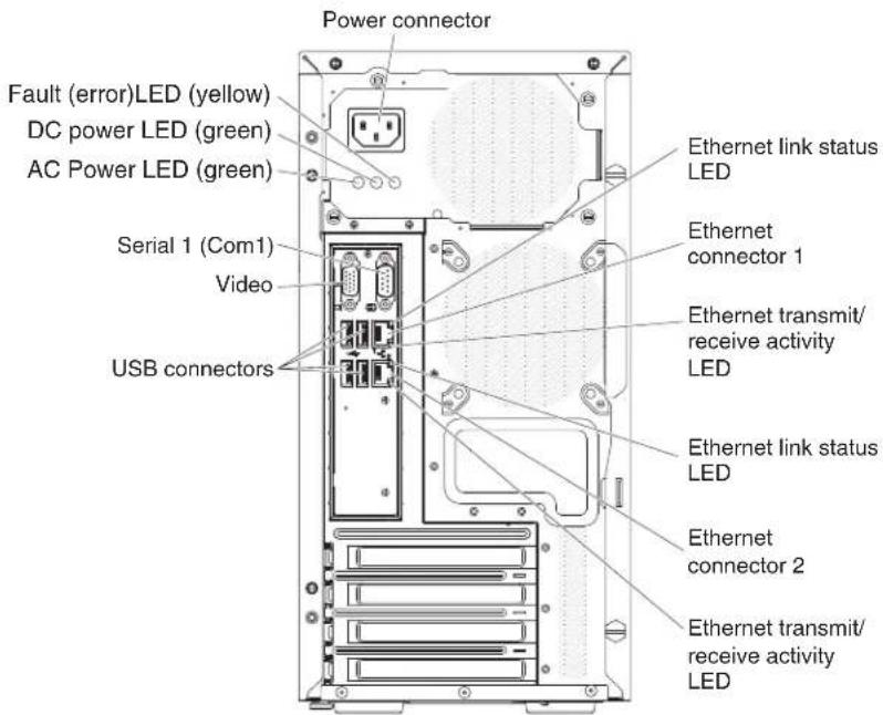
Figure71.LEDsandconnectorsontherearofthe4Uservermodelwithnon-hot-swappower supplies(powersupplyLEDspresent)

Figure 72. LEDs and connectors on the rear of the 5U server model with hot-swap power supplies
The following table describes the problem that are indicated by various combinations of the power supply LEDs and suggested action to correct the detected problems.
Table11.Power-supplyLEDs
| ACPower-supplyLEDs | DescriptionAction | NotesACDCError | |||
| OnOn | OffNormal | operation | |||
| OffOff | OffNoacpowerto | theserveroraproblemwiththeacpowersource. | 1. Checktheacpowertotheserver.2. Makesurethatthe power cordisconnected toafunctioningpowersource.3. Restart the server. If the error remains,check thepower-supplyLEDs.4. If the problem remains, replace thepower-supply. | This isanormalcondition whennoac powerispresent. | |
| On | OffOff | Faulty system | board orfaultypower supply | 1. Turn offtheserverand disconnectthepower cordfrom theserver;then,reconnect thepowercord.2. If thesystemboarderror (fault)LEDis notlit,replacethe powersupply.3. (Trained technicianonly)Ifthesystemboard error LEDislit,replace thesystem board. | Typically indicatesthat apowersupplyis notfullyseated.This isanormalcondition beforeturning onthesystem. |
| OnOffor Flashing | OnFaultypower supply | Replacethepowersupply. | |||
| OnOnOffNormal | operation | ||||
| OnOnOnPowersupply | faultybutstill operational | Replacethepowersupply. | |||
System pulse LEDs
This section describes the system pulse LEDs on the system board that monitors the system power-on and power-off and boot progress.
The following LEDs are on the system board and monitor the system power-on and power-off sequencing and boot progress (see "System-board LEDs" on page 34 for the location of these LEDs).
Table12.SystempulseLEDs
| LED | Description | Action |
| RTMMheartbeat | Power-onandpower-off sequencing. | 1. IftheLEDblinksat1Hz,itisfunctioning properlyandnoactionisnecessary.2. IftheLEDisnotblinking,(trained technicianonly)replacethesystemboard. |
| IMM2heartbeat | IMM2heartbeatbootprocess.Thefollowingstepsdescribethedifferent stagesoftheIMM2heartbeatsequencing process.1. WhenthisLEDisblinkingfast (approximately4Hz),thisindicates,thatthe IMM2codeisintheloadingprocess.2. WhenthisLEDgoesoffmomentarily,this indicatesthattheIMM2codehasloaded completely.3. WhenthisLEDgoesoffmomentarilyand thenstartsblinkingslowing(approximately 1Hz),thisindicatesthatIMM2isfully operational.Youcannowpressthe power-controlbuttontopower-onthe server.4. IfthisLEDdoesnotblinkwithin30 secondsofconnectingapowersourceto theserver,(trainedtechnicianonly)replace thesystemboard. |
Eventlogs
ErrorcodesandmessagesaredisplayedinPOSTeventlog,system-eventlog, integratedmanagementmodule(IMM2)eventlog,andDSAeventlog.
- POST event log: This log contains the most recent error codes and messages that were generated during POST. You can view the content of the POST event log from the Setuputility (see "Starting the Setuputility" on page 98). Form more information about POSTerrorcodes, see Appendix B, "UEFI/POST diagnostic codes," on page 501.
- System-event log: This log contains POST and system management interrupt (SMI)eventsandalleventsthataregeneratedbythebaseboardmanagement controllerthatisembeddedintheintegratedmanagementmodule(IMM).You canviewthecontentsofthesystem-eventlogthroughtheSetuputilityand throughtheDynamicSystemAnalysis(DSA)program(asIPMIeventlog). Thesystem-eventlogislimitedinsize.Whenitisfull,newentrieswillnot overwriteexistingentries;therefore,youmustperiodicallyclearthe system-eventlogthroughtheSetuputility.Whenyouaretroubleshootingan error,youmighthavetosaveandthenclearthesystem-eventlogtomakethe mostrecenteventsavailableforanalysis.Formoreinformationaboutthe system-eventlog,seeAppendixA,"IntegratedmanagementmoduleII(IMM2) errormessages,"onpage327.
Messagesarelistedontheleftsideofthescreen,anddetailsabouttheselectedmessagearedisplayedontherightsideofthescreen.Tomovefromoneentrytothenext,usetheUpArrow(↑)andDownArrow(↓)keys.
SomeIMMsensorscauseassertioneventstobelloggedwhentheirsetpointsare reached.Whenasetpointconditionnolongerexists,acorrespondingdeassertion eventislogged.However,notalleventsareassertion-typeevents.
- Integrated management module II (IMM2) event log: This log contains a filtered subset of all IMM, POST, and system management interrupt (SMI) events. You can view the IMMeventlog through the IMMwebinterface. For more information, see "Logging onto the web interface" on page 108. You can also view the IMMeventlog through the Dynamic System Analysis (DSA) program (as the ASMeventlog). Form more information about IMMerror messages, see Appendix A, "Integrated management module II (IMM2) error messages," on page 327.
- DSA event log: This log is generated by the Dynamic System Analysis (DSA) program, and itisachronologically ordered mergeofthesystem-eventlog(as theIPMEventlog), theIMMchassis-eventlog (astheASMeventlog), and the operating-systemeventlogs. You can view the DSA event log through the DSA program (see "Viewingeventlog without restarting the server" on page 134). Form more information about DSA and DSAmessages, see "IBMDynamicSystem Analysis" on page 136 and Appendix C, "DSAdiagnostictestresults," on page 515.
ViewingeventlogsthroughtheSetuputility
Use this information to view the event log through the Setup utility.
Aboutthistask
ToviewthePOSTeventlogorsystem-eventlog,completethefollowingsteps:
Procedure
- Turnontheserver.
- When the prompt
Setup is displayed, press F1. If you have set both a power-onpasswordandanadministratorpassword,youmustypethe administratorpasswordtoviewtheeventlogs. - SelectSystemEventLogsanduseoneofthefollowingprocedures:
• To view the POST event log, select POST Event Viewers.
•Toviewthesystem-eventlog,selectSystemEventLog.
Viewingeventlogswithoutrestartingtheserver
Use this information to view the event log without restarting the server.
If the server is nothing and the IM misconnected to an network, methods are available for out view one or more event logs without having to start the server.
If you have installed Dynamic System Analysis (DSA) Portable, you can use it to view the system-event log (asthe IPMI event log), or the IM Mevent log (asthe ASMevent log), the operating system event logs, orthemerged DS A log. You can also use DSAP reboot to view these logs, although you must restart these vererto use DSAP reboot. To install DSAP portable or check for and download a later version of DSAP reboot CD image, goto http://www.ibm.com/support/entry/portal/doc display?Indocid=SERV-DSA.
IfIPMItoolisinstalledintheserver,youcanuseittoviewthesystem-eventlog. MostrecentversionsoftheLinuxoperatingsystemcomewithacurrentversionof IPMItool.ForanoverviewofIPMI,gotohttp://www.ibm.com/developerworks/ linux/blueprints/andclickUsingIntelligentPlatformManagementInterface (IPMI)onIBMLinuxplatforms.
YoucanviewtheIMMeventlogthroughtheEventLoglinkintheintegrated managementmoduleII(IMM2)webinterface.Formoreinformation,see"Logging ontothewebinterface"onpage108.
The following table describes the method that you can set to view the event logs, depending on the condition of the server. The first three conditions generally do not require that you start the server.
Table13.Methodsforviewingeventlogs
| ConditionAction | |
| Theserverisnothungandisconnectedtoanetwork(usinganoperatingsystemcontrollednetworkports). | Useanyofthefollowingmethods:RunDSAPortabletoviewthediagnosticeventlog (requiresIPMIdriver)orcreateanoutputfilethatyou cansendtoIBMserviceandsupport(usingftpor localcopy).UseIPMItooltoviewthesystem-eventlog(requires IPMIdriver).UsethewebbrowserinterfacetotheIMM2toview thesystem-eventloglocally(requiresRNDISUSB LANdriver). |
| Theserverisnothungandisnotconnectedtoanetwork(usinganoperatingsystemcontrollednetworkports). | RunDSAPortabletoviewthediagnosticeventlog (requiresIPMIdriver)orcreateanoutputfilethatyou cansendtoIBMserviceandsupport(usingftpor localcopy).UseIPMItooltoviewthesystem-eventlog(requires IPMIdriver).UsethewebbrowserinterfacetotheIMM2toview thesystem-eventloglocally(requiresRNDISUSB LANdriver). |
| Theserverisnohungandtheintegratedmanagement moduleII(IMM2)isconnectedtoanetwork. | Inawebbrowser,typetheIPaddressfortheIMM2and gototheEventLogpage.Formoreinformation,see "ObtainingtheIMMhostname"onpage107and "Loggingontothewebinterface"onpage108. |
| Theserverishung,andnocommunicationcanbemade withtheIMM. | IfDSAPrebootisinstalled,restarttheserverandpress F2 tostartDSAPrebootandviewtheeventlogs(see "RunningDSAPrebootdiagnosticprograms"onpage 138 formoreinformation).Alternatively,youcanrestarttheserverandpressF1 tostarttheSetuputilityandviewthePOSTeventlog orsystem-eventlog.Formoreinformation,see "ViewingeventlogsthroughtheSetuputility"on page134. |
Clearingtheeventlogs
Usethisinformationtocleartheeventlogs.
Aboutthistask
Tocleartheeventlogs, completethefollowingsteps.
Note: The POSTerrorlogis automatically clearedeachtimetheserveris restarted.
Procedure
- Turnontheserver.
- When the prompt
Setup is displayed, press F1. If you have set both a power-onpasswordandanadministratorpassword,youmusttypethe administratorpasswordtoviewtheeventlogs. - To clear the IMM system-event log, select System Event Logs > Clear System EventLog, then pressEnter twice.
POST
When youturnontheserver, it performs a series of test to check the operation of the server components and some optional devices in the server. This series of tests is called the power-onself-test, or POST.
Note: This server does not use beepcodes for server status.
If a power-on password disset, you must typethe password and press Enter (when you are prompted), for POSTtorun.
IfPOSTdetectsaproblem, anerrormessageisdisplayed. SeeAppendixB, "UEFI/POSTdiagnosticcodes," onpage501formoreinformation.
IfPOSTdetectsaproblem, an error message is sent to the POSTeventlog, see "Eventlogs" on page 133 from more information.
IBMDynamicSystemAnalysis
IBMDynamicSystemAnalysis(DSA) collects and analyzes system information to aid indiagnosing server problems.
DSAcollectsthefollowinginformationabouttheserver:
•Drivehealthinformation
• EventlogsforServeRAIDcontrollersandserviceprocessors
•Hardwareinventory,includingPCIandUSBinformation
- Installedapplicationsandhotfixes(availableinDSAPortableonly)
- Kernelmodules(availableinDSAPortableonly)
•Lightpathdiagnosticsstatus
•Networkinterfacesandsettings
•Performancedataanddetailsaboutprocessesthatarerunning
•RAIDcontrollerconfiguration
•Serviceprocessor(integratedmanagementmodule)statusandconfiguration
- Systemconfiguration
•Vitalproductdataandfirmwareinformation
•IMM2configurationinformation
•IMM2environmentalsinformation
- Optioncarddriverandfirmwareinformation
Forsystem-specificinformationabouttheactionthatyoushouldtakeasresultof amessagethatDSAgenerates,seeAppendixC,"DSAdiagnostictestresults,"on page515.
If you cannot find a problem by using DSA, see "Solving undetermined problems" on page 158 for information about testing the server.
Note: DSAPrebootmightappeartobeunresponsivewhenyoustarttheprogram. Thisisnormaloperationwhiletheprogramloads.
MakesurethattheserverhasthelatestversionoftheDSAcode.ToobtainDSA code and the Dynamic System Analysis Installation and User's Guide, go to http://www.ibm.com/support/entry/portal/docdisplay?Indocid=SERV-DSA.
DSAeditions
TwoeditionsofDynamicSystemAnalysisareavailable.
•DSAPortable
DSAPortableEditionrunswithintheoperatingsystem;youdonothaveto restarttheservertorunit.Itispackagedasaself-extractingfilethatyou downloadfromtheweb.Whenyourunthefile,itself-extractstoatemporary folderandperformscomprehensivecollectionofhardwareandoperating-system information.Afteritruns,itautomaticallydeletesthetemporaryfilesandfolder andleavestheresultsofthedatacollectionanddiagnosticsontheserver.
If you are unable to start the server, use DSAPortable.
•DSAPreboot
DSAPrebootrunsoutsideoftheoperatingsystem;youmustrestarttheserverto runit.Itisprovidedintheflashmemoryontheserver,oryoucancreatea bootablemediasuchasaCD,DVD,ISO,USB,orPXEusingtheIBM ToolsCenterBootableMediaCreator(BoMC).Formoredetails,seetheBoMC
UserGuideathttp://www.ibm.com/support/entry/portal/
docdisplay?Indocid=TOOL-BOMC. In addition to the capabilities of the other edition of DSA, DSAPreboot includes diagnostic routines that would be disruptivector unwithin the operating system environment (such as resetting devices and causing loss of network connectivity). Ithasagraphical user interface that you can usetospecify which diagnostic storunandtoview the diagnostic and data collection results.
DSAPrebootprovidesdiagnosticsforthefollowingsystemcomponents,ifthey areinstalled:
-Emulexnetworkadapter
-Opticaldevices(CDorDVD)
-Tapedrives(SCSI,SAS,orSATA)
-Memory
-Microprocessor
-Checkpointpanel
-I2Cbus
-SASandSATAdrives
-LSIController
-Broadcomnetworkadapter
-FusionIOstorage
-IntelGPU
-NvidiaGPU
If you are able to start the server orify you need comprehensive diagnostics, use DSAPreboot.
Formoreinformationandtodownloadtheutilities,gotohttp://www.ibm.com/support/entry/portal/docdisplay?Indocid=SERV-DSA.
RunningDSAPrebootdiagnosticprograms
UsethisinformationtoruntheDSAPrebootdiagnosticprograms.
Aboutthistask
Note: The DSAmemorytestmighttakeup to 30 minute test or run. If the problem is not a memory problem, skipthememory test.
ToruntheDSAPrebootdiagnosticprograms,completethefollowingsteps:
Procedure
- If the server is running, turn off the server and all attached devices.
- Turnonallattacheddevices; then, turnontheserver.
- When the prompt
Diagnostics is displayed, press F2.
Note: The DSAPrebootdiagnosticprogram might appeartobeunresponsive for an unusual length to timewhen you start the program. This is normal operation while the program loads. Theloading process may take up to 10 minutes.
- Optionally, select Quit to DSA to exit from the stand-alone memory diagnostic program.
Note: After you exit from the stand-alone memory diagnostic environment, you must restart these server to access the stand-alone memory diagnostic environment again.
- Type gui to display the graphical user interface, or type cmd to display the DSAinteractivemenu.
- Follow the instructions on the screentoselect the diagnostic test torun.
Results
If the diagnostic programs donot detect any hardware errors but the problem remains during normal server operation, as software error might be the cause. If you suspect as software problem, see the information that comes with your software.
Asingleproblemmightcausemorethanoneerrormessage.Whenthishappens, correctthecauseofthefirsterrormessage.Theothererrormessagesusuallywill notoccurthenexttimeyourunthediagnosticprograms.
If the server stops during testing and you cannot continue, restart the server and try running the DSAP reboot diagnostic programs again. If the problem remains, replace the component that was being tested when the server stopped.
Diagnostictextmessages
Diagnostictextmessagesaredisplayedwhilethetestsarerunning.
Adiagnostictextmessagecontainsoneofthefollowingresults:
Passed: Thetestwascompletedwithoutanyerrors.
Failed: Thetestdetectedanerror.
Aborted: Thetestcouldnotproceedbecauseoftheserverconfiguration
Additional information concerning test failures is available in the extended diagnostic results foreach test.
ViewingthetestlogresultsandtransferringtheDSAcollection
Use this information to view the test log results and transferring the DSA collection.
Aboutthistask
Toviewthetestlogfortheresultswhentetestsarecompleted,clicktheSuccess linkintheStatuscolumn,ifyouarerunningtheDSAgraphicaluserinterface,or type:x toexittheExecuteTestsmenu,ifyouarerunningtheDSAinteractive menu,orselectDiagnosticEventLoginthegraphicaluserinterface.Totransfer DSAPrebootcollectionstoanexternalUSBdevice,typethecopy commandinthe DSAinteractivemenu.
Procedure
- If you are running the DSA graphical user interface (GUI), click the Success link intheStatuscolumn.
- If you are running the DSA interactive menu (CLI), type :x to exit the Execute Testsmenu;then,selectcompletedteststoviewtheresults.
Results
YoucanalsosendtheDSAerrorlogtoIBMsupporttoaidindiagnosingthe serverproblems.
Automatedservicerequest(callhome)
IBMprovidestoolsthatcanautomaticallycollectandsenddataorcallIBM Supportwhenanerrorisdetected.
ThesetoolscanhelpIBMSupportspeeduptheprocessofdiagnosingproblems. Thefollowingsectionsprovideinformationaboutthecallhometools.
IBMElectronicServiceAgent
IBMElectronicServiceAgentmonitors,tracks,andcapturessystemhardware errorsandhardwareandsoftwareinventoryinformation,andreportsserviceable problemsdirectlytoIBMSupport.
Youcanalsochoosetocollectdatamanually.Itusesminimalsystemresources, andcanbedownloadedfromtheIBMwebsite.Formoreinformationandto downloadIBMElectronicServiceAgent,gotohttp://www-01.ibm.com/support/esa/.
Errormessages
ThissectionprovidesthelistoferrorcodesandmessagesforUEF1/POST,IMM2, andDSAthataregeneratedwhenaproblemisdetected.
See AppendixB, "UEFI/POSTdiagnosticcodes," onpage501, AppendixA, "IntegratedmanagementmoduleII(IMM2)errormessages," onpage327, and AppendixC, "DSAdiagnostictestresults," onpage515formoreinformation.
Troubleshootingbysymptom
Usethetroubleshootingtablestofindsolutionstoproblemsthathaveidentifiable symptoms.
Aboutthistask
If you cannot find solution to the problem in the setables, see Appendix C, "DSA diagnostic test results," on page 515 for information about testing the server and "Running DSAPreboot diagnostic programs" on page 138 for additional information about running DSAPreboot program. For additional information to help you solve problems, see "Starthere" on page 119.
If you have just added new software or anew optional device and the server is not working, complete the following steps before you use the troubleshooting tables:
Procedure
- Check the system-error LED on the front information panel; if it is lit, check the lightpath diagnostics LEDs (see "Lightpath diagnostics" on page 126).
- Removethesoftwareordevicethatyoujustadded.
- RunIBMDynamicSystemAnalysis(DSA)todeterminewhethertheserveris runningcorrectly(forinformationaboutusingDSA,seeAppendixC,"DSA diagnostictestresults,"onpage515).
- Reinstallthenewsoftwareornewdevice.
Generalproblems
Table14. Generalsymptomsandactions
| Follow the suggested actions in the order in which they are listed in the Action column until the problem is solved.If an action step is preceded by “(Trained technician only)”, that step must be performed only by a trained technician.Go to the IBM support website at http://www.ibm.com/supportportal to check for technical information, hints, tips,andnewdevicedriversortosubmitarequestforinformation. | |
| SymptomAction | |
| Acoverlatchisbroken,anLED isnotworking,orasimilar problemhasoccurred. | IfthepartisaCRU,replaceit.Ifthepartisamicroprocessororthesystemboard, thepartmustbereplacedbyatrainedtechnician. |
| Theserverishungwhilethe screenison.Cannotstartthe SetuputilitybypassingF1. | See“Nx-bootfailure”onpage164formoreinformation.See“Recoveringtheserverfirmware(UEFlupdatefailure)”onpage161for moreinformation. |
Harddiskdriveproblems
Table15. Harddiskdrivesymptomsandactions
| Follow the suggested actions in the order in which they are listed in the Action column until the problem is solved.If an action step is preceded by “(Trained technician only)”, that step must be performed only by a trained technician.Go to the IBM support website at http://www.ibm.com/supportportal to check for technical information, hints, tips,andnewdevicedriversortosubmitarequestforinformation. | |
| SymptomAction | |
| Notalldrivesarerecognizedby theharddiskdrivediagnostictests. | Removethedrivethatisindicatedbythediagnostictests;then,runtheharddiskdrivediagnostictestsagain.Iftheremainingdrivesarerecognized,replacethe drivethatyouremovedwithanewone. |
| Theserverstopsresponding duringtheharddiskdrive diagnostictest. | Removetheharddiskdrivethatwasbeingtestedwhentheserverstopped responding,andrunthediagnostictestagain.Iftheharddiskdrivediagnostictestrunssuccessfully,replacethedrivethatyouremovedwithanewone. |
| Aharddiskdrivewasnot detectedwhiletheoperating systemwasbeingstarted. | Reseatallharddiskdrivesandcables;then,runtheharddiskdrivediagnostictestsagain. |
| Aharddiskdrivepassesthe diagnosticFixedDiskTest,but theproblemremains. | RunthediagnosticSCSIFixedDiskTest(see“RunningDSAPrebootdiagnosticprograms”onpage138).Note:ThistestisnotavailableonserversthathaveRAIDarraysorserversthat haveSATAharddiskdrives. |
| Aharddiskdrivehasfailed, andtheassociatedyellowhard diskdrivestatusLEDslit.(Hot-swapharddiskdrives) | 1. Re-configuretheintegratedSAS/SATAcontrollerwithRAIDcapabilitiesand thedevicesthatareattachedoit.2. RuntheDSAdiskdrivetest(see“IBM DynamicSystemAnalysis”onpage 136).3. Ifthedrivefailsthetest,replacethedrive. |
| Anewlyinstalledharddisk driveisnotrecognized. | 1. ObservetheassociatedyellowharddiskdrivestatusLED.IftheLEDislit,it indicatesadrivefault.2. IftheLEDislit,removethedrivefromthebay,wait45seconds,andreinsert thedrive,makingsurethatthedriveassemblyconnectstotheharddisk drivebackplane.3. ObservetheassociatedgreenharddiskdriveactivityLEDandtheyellow statusLED:IfthegreenactivityLEDisflashingandtheyellowstatusLEDisnotlit, thedriveisrecognizedbythecontrollerandisworkingcorrectly.Runthe DSAharddiskdrivetesttodeterminewhetherthedriveisdetected.IfthegreenactivityLEDisflashingandtheyellowstatusLEDisflashing slowly,thedriveisrecognizedbythecontrollerandisrebuilding.IfneitherLEDislitorflashing,checktheharddiskdrivebackplane(goto step4).IfthegreenactivityLEDisflashingandtheyellowstatusLEDislit, replacethedrive.IftheactivityoftheLEDsremainsthesame,gotostep4. IftheactivityoftheLEDschanges,returntostep1.4. Makesurethattheharddiskdrivebackplaneiscorrectlyseated.Whenitis correctlyseated,thedriveassembliescorrectlyconnecttothebackplane withoutbowingorcausingmovementofthebackplane.5. Reseatthebackplanepowercableandreptsteps1through3.6. Reseatthebackplanesignalcableandreptsteps1through3.7. Reseatthebackplaneconfigurationcableandreptsteps1through3.8. Suspectthebackplanesignalcableorthebackplane:Replaceheaffectedbackplanesignalcable.Replaceheaffectedbackplane.9. RuntheDSAtestsfortheSAS/SATAadapterandharddiskdrives(see“IBM DynamicSystemAnalysis”onpage136).Iftheadapterpassesthetestbutthedrivesarenotrecognized,replacethe backplanesignalcableandrunthetestssagain.Replacehebackplane.Iftheadapterfailsthetest,disconnectthebackplanesignalcablefromthe adapterandrunthetestssagain.Iftheadapterfailsthetest,replacetheadapter.10. See“Problemderminationtips”onpage159. |
| Multipleharddiskdrivesfail.Makesurethattheharddiskdrive,SAS/SATARADadapter,andserverdevice driversandfirmwareareatthelatestlevel.Important:Someclustersolutionsrequirespecificcodelevelsorcoordinatedcode updates.Ifthedeviceispartofaclustersolution,verifythatthelatestlevelof codeissupportedfortheclustersolutionbeforeyouupdatethecode. | |
| Multipleharddiskdrivesare offline. | 1. Reviewthestoragesubsystemlogsforindicationsofproblemswithinthe storagesubsystem,suchasbackplaneorcableproblems.See“Problemderminationtips”onpage159. |
| Areplacementharddiskdrive doesnotrebuild. | 1. Makesurethattheharddiskdriveisrecognizedbytheadapter(thegreen harddiskdriveactivityLEDisflashing).2. ReviewtheSAS/SATARAIDadapterdocumentationtodeterminethecorrect configurationparametersandsettings. |
| Agreenharddiskdriveactivity LEDdoesnotaccurately representtheactualstateofthe associateddrive.(Hot-swap harddiskdrives) | 1. IfthegreenharddiskdriveactivityLEDdoesnotflashwhenthedriveisin use,runtheDSAdiskdrivetest(see“IBM DynamicSystemAnalysis”onpage 136).2. Useoneofthefollowingprocedures:Ifthedrivepassesthetest,replacethebackplane.Ifthedrivefailsthetest,replacethedrive. |
| Anyellowharddiskdrive statusLEDdoesnotaccurately representtheactualstateofthe associateddrive.(Hot-swap harddiskdrives) | 1. IftheyellowharddiskdriveLEDandtheRAIDadaptersoftwaredonot indicatethesamestatusforthedrive,completethefollowingsteps:a. Turnofftheserver.b. ReseattheSAS/SATAadapter.c. Reseatthebackplaneconfigurationcable,signalcable,andbackplane powercable.d. Reseattheharddiskdrive.e. TurnontheserverandobservetheactivityoftheharddiskdriveLEDs.2. See“Problem determinationtips”onpage159. |
CD/DVDdriveproblems
Table 16. CD/DVD drive's symptoms and actions
| Follow the suggested actions in the order in which they are listed in the Action column until the problem is solved.If an action step is preceded by “(Trained technician only)”, that step must be performed only by a Trained technician.Go to the IBM support website at http://www.ibm.com/supportporta to check for technical information, hints, tips,andnewdevicedriversortosubmitarequestforinformation. | |
| SymptomAction | |
| TheoptionalDVDdriveisnot recognized. | 1. Makesurethat:•TheSATAconnectortowhichtheDVDdriveisattached(primaryor secondary)isenabledintheSetuputility.•Allcablesandjumpersareinstalledcorrectly.•ThecorrectdevidedriverisinstalledfortheDVDdrive.2. RuntheDVDdrivediagnosticprograms.3. Reseatthefollowingcomponents:a. DVDdriveb. DVDdrivecable4. Replacethecomponentslistedinstep3oneatatime,intheordershown, restartingtheservereachtime.5. (Trainedtechnicianonly)Replacethesystemboard. |
| ACDorDVDisnotworking correctly. | 1. CleantheCDorDVD.2. ReplacetheCDorDVDwithnewCDorDVDmedia.3. RuntheDVDdrivediagnosticprograms.4. ReseattheDVDdrive.5. ReplacetheDVDdrive. |
| TheDVDdrivetrainisnot working. | 1. Makesurethattheserveristurnedon.2. Inserttheendofastraightenedpaperclipintothemanualtray-release opening.3. ReseattheDVDdrive.4. ReplacetheDVDdrive. |
Hypervisorproblems
Table17. Hypervisor'ssymptomsandactions
| Follow the suggested actions in the order in which they are listed in the Action column until the problem is solved.If an action step is preceded by “(Trained technician only)”, that step must be performed only by a trained technician.Go to the IBM support website athttp://www.ibm.com/supportportato check for technical information, hints, tips,andnewdevicedriversortosubmitarequestforinformation. | |
| SymptomAction | |
| Ifanoptionalembedded hypervisorflashdeviceisnot listedintheexpectedboot order,doesnotappearinthe listofbootdevices,orasimilar problemhasoccurred. | 1. Makesurethattheoptionalembeddedhypervisorflashdeviceisselectedon thebootmanagerSelect Boot Device atstartup.2. Makesurethattheembeddedhypervisorflashdeviceisseatedinthe connectorcorrectly(see“RemovingtheUSBembeddedhypervisorflash device”onpage227and“ReplacingtheUSBembeddedhypervisorflash device”onpage230).3. Seethedocumentationthatcomeswiththeoptionalembeddedhypervisor flashdeviceforsetupandconfigurationinformation.4. Makesurethatothersoftwareworksontheserver. |
Intermittentproblems
Use this information to solve intermittent problems.
Table18. Intermittentproblemsandactions
| Follow the suggested actions in the order in which they are listed in the Action column until the problem is solved.If an action step is preceded by “(Trained technician only),” that step must be performed only by a trained technician.Go to the IBM support website at http://www.ibm.com/supportportal/ to check for technical information, hints, tips,andnewdevicedriversortosubmitarequestforinformation. | |
| SymptomAction | |
| Aproblemoccursonlyoccasionallyandisdifficulttodiagnose. | 1. Makesurethat:Allcablesandcordsareconnectedsecurelytotherearoftheserverand attacheddevices.Whentheserveristurnedon,airisflowingfromthefangrille.Ifthereisno airflow,thefanisnotworking.Thiscancausetheservertooverheatand shutdown.2. Checkthesystem-errorlogorIMMeventlogs(see“Eventlogs”onpage133). |
| Theserverresets(restarts)occasionally. | 1. IftheresetoccursduringPOSTandthePOSTwatchdogtimerisenabled(click System Settings >Recovery>System Recovery>POST Watchdog Timer in theSetuputilitytoseethePOSTwatchdogsetting),makesurethatsufficient time is allowed in the watchdog timeout value (POST Watchdog Timer). If the servercontinuestoresetduringPOST,seeAppendixB,“UEFI/POST diagnosticcodes,”onpage501andAppendixC,“DSAdiagnostictestresults,”onpage515.2. Ifneitherconditionapplies,checkthesystem-errorlogorIMMsystem-event log(see“Eventlogs”onpage133). |
Keyboard, mouse, or USB-device problems
Table19. Keyboard, mouse, or USB-device'ssymptomsandactions
| Follow the suggested actions in the order in which they are listed in the Action column until the problem is solved.If an action step is preceded by “(Trained technician only)”, that step must be performed only by a trained technician.Go to the IBM support website athttp://www.ibm.com/supportportato check for technical information, hints, tips,andnewdevicedriversortosubmitarequestforinformation. | |
| SymptomAction | |
| Allorsomekeysonthe keyboarddonotwork. | 1. Makesurethat:Thekeyboardcableissecurelyconnected.Theserverandthemonitorareturnedon.IfyouareusingaUSBkeyboard,runtheSetuputilityandenablekeyboardless operation.IfyouareusingaUSBkeyboardanditisconnectedtoaUSBhub,disconnect thekeyboardfromthehubandconnectitdirectlytotheserver.Replacethekeyboard. |
| ThemouseorUSB-devicedoes notwork. | 1. Makesurethat:ThemouseorUSBdevicecableissecurelyconnectedtotheserver.ThemouseorUSBdevicedriversareinstalledcorrectly.Theserverandthemonitorareturnedon.ThemouseoptionisenabledintheSetuputility.IfyouareusingaUSBmouseorUSBdeviceanditisconnectedtoaUSBhub, disconnectthemouseorUSBdevicefromthehubandconnectitdirectlyto theserver.ReplacethemouseorUSB-device. |
Memoryproblems
Table20. Memoryproblemsandactions
| Follow the suggested actions in the order in which they are listed in the Action column until the problem is solved.If an action step is preceded by “(Trained technician only)”, that step must be performed only by a trained technician.Go to the IBM support website at http://www.ibm.com/supportportal to check for technical information, hints, tips,andnewdevicedriversortosubmitarequestforinformation. | |
| SymptomAction | |
| Theamountofsystemmemory thatisdisplayedislessthanthe amountofinstalledphysical memory. | Note:EachtimeyouinstallorremoveaDIMM,youmustdisconnecttheserver fromthepowersource;then,wait10secondsbeforererestartingtheserver.1. Makesurethat:NoerrorLEDsarelitontheoperatorinformationpanel.NoDIMMerrorLEDsarelitonthesystemboard.Memoryymirroredchanneldoesnotaccountforthediscrepancy.Thememorymodulesareseatedcorrectly.Youhaveinstalledthecorrecttypeofmemory.Ifyouchangedthememory,youupdatedthememoryconfigurationinthe Setuputility.Allbanksofmemoryareenabled.Theservermighthaveautomatically disabledamemorybankwhenitdetectedaproblem,oramemorybank mighthavebeenmanuallydisabled.Thereisnomemorymismatchwhentheserverisatthemminimummemory configuration.2. ReseattheDIMMs,andthenrestarttheserver.3. CheckthePOSTerrorlog:IfaDIMMwasdisabledbyasystems-managementinterrupt(SMI),replace theDIMM.IfaDIMMwasdisabledbytheuserorbyPOST,reseattheDIMM;then,run theSetuputilityandenabletheDIMM.4. CheckthatallDIMMsareinitializedintheSetuputility;then,runmemory diagnostics(see“RunningDSAPrebootdiagnosticprograms”onpage138).5. ReversetheDIMMsbetweenhechannels(ofthesamemicroprocessor),and thenrestarttheserver.IftheproblemsrelatedtoaDIMM,replacethefailing DIMM.6. Re-enableallDIMMsusingtheSetuputility,andthenrestarttheserver.(Trainedtechnicianonly)InstallthefailingDIMMintoaDIMMconnectorfor microprocessor2(ifinstalled)toverifythattheproblemisnotthe microprocessorortheDIMMconnector.8. (Trainedtechnicianonly)Replacethesystemboard. |
| Follow the suggested actions in the order in which they are listed in the Action column until the problem is solved.If an action step is preceded by “(Trained technician only)”, that step must be performed only by a trained technician.Go to the IBM support website athttp://www.ibm.com/supportportato check for technical information, hints, tips,andnewdevicedriversortosubmitarequestforinformation. | |
| SymptomAction | |
| MultipleDIMMsinachannel areidentifiedasfailing. | Note:EachtimeyouinstallorremoveaDIMM,youmustdisconnecttheserver fromthepowersource;then,wait10secondsbeforererestartingtheserver.1. ReseattheDIMMs;then,restarttheserver.2. Removethehighest-numberedDIMMofthosethatareidentifiedandreplaceit withanidenticalknowngoodDIMM;then,restarttheserver.Repeatas necessary.IfthefailurescontinueafterallidentifiedDIMMsarereplaced,goto step4.3. ReturntheremovedDIMMs,oneatatime,totheiroriginalconnectors, restartingtheserveraftereachDIMM,untilaDIMMfails.Replaceeachfailing DIMMwithanidenticalknowngoodDIMM,restartingtheserveraftereach DIMMreplacement.Repeatstep3untilyouhavetestedallremovedDIMMs.4. Replacethehighest-numberedDIMMofthoseidentified;then,restartthe server.Repeatasnecessary.5. ReversetheDIMMsbetweenhechannels(ofthesamemicroprocessor),and thenrestarttheserver.IftheproblemisrelatedtoaDIMM,replacethefailing DIMM.6. (Trainedtechnicianonly)InstallthefailingDIMMintoaDIMMconnectorfor microprocessor2(ifinstalled)toverifythattheproblemisnotthe microprocessorortheDIMMconnector.7. (Trainedtechnicianonly)Replacethesystemboard. |
Microprocessorproblems
Table21. Microprocessor'ssymptomsandactions
| Follow the suggested actions in the order in which they are listed in the Action column until the problem is solved.If an action step is preceded by “(Trained technician only)”, that step must be performed only by a trained technician.Go to the IBM support website at http://www.ibm.com/supportporta to check for technical information, hints, tips,andnewdevicedriversortosubmitarequestforinformation. | |
| SymptomAction | |
| Theservergoesdirectlytothe POSTEventViewerwhenitis turnedon. | 1. CorrectanyerrorsthatareindicatedbythelightpathdiagnosticsLEDs(see "Lightpathdiagnostics" onpage126).2. Makesurethattheserversupportsallthemicroprocessorsandthatthe microprocessorsmatchinspeedandcachesize.Toviewthemicroprocessor information, run the Setup utility and select System Information > System Summary>ProcessorDetails.3. (Trainedtechnicianonly)Makesurethatmicroprocessor1isseatedcorrectly.4. (Trainedtechnicianonly)Removemicroprocessor2andrestarttheserver.5. Replacethefollowingcomponentsoneatatime,intheordershown,restarting theservereachtime:a. (Trainedtechnicianonly)Microprocessorb. (Trainedtechnicianonly)Systemboard |
Monitorproblems
SomeIBMmonitorshavetheirownself-tests.Ifyoususpectaproblemwithyour monitor,seethedocumentationthatcomeswiththemonitorforinstructionsfor testingandadjustingthemonitor.Ifyoucannotdiagnosetheproblem,callfor service.
Table22. Monitorandvideo'ssymptomsandactions
| Follow the suggested actions in the order in which they are listed in the Action column until the problem is solved.If an action step is preceded by “(Trained technician only)”, that step must be performed only by a trained technician.Go to the IBM support website at http://www.ibm.com/supportportal to check for technical information, hints, tips,andnewdevicedriversortosubmitarequestforinformation. | |
| SymptomAction | |
| Testingthemonitor. | 1. Makesurethatthemonitorcablesarefirmlyconnected.2. Tryusingadifferentmonitorontheserver,ortryusingthemonitorthatis beingtestedonadifferentserver.3. Runthediagnosticprograms.Ifthemonitorpassesthediagnosticprograms, theproblemmightbeavideodevicedriver.4. (Trainedtechnicianonly)Replacethesystemboard. |
| Thescreenisblank. | 1. IftheserverisattachedtoaKVMswitch,bypasstheKVMswitchtoeliminate itasaposiblcauseoftheproblem:connectthemonitorcabledirectlytothe correctconnectorontherearoftheserver.2. TheIMM2remotepresencefunctionisdisabledifyuinstallanoptionalvideo adapter.TousetheIMM2remotepresencefunction,removetheoptionalvideo adapter.3. Iftheserverinstalledwiththegraphicaladapterswhileturningontheserver, theIBMlogodisplaysonthescreenafterapproximately3minutes.Thiss normaloperationwhilethesystemloads.4. Makesurethat:·Theserveristurnedon.Ifthereisnopowertotheserver,see“Power problems”onpage152. ·Themonitorcablesareconnectedcorrectly. ·Themonitoristurnedonandthebrightnessandcontrastcontrolsare adjustedcorrectly.5. Makesurethatthecorrectserveriscontrollingthemonitor,ifapplicable.6. Makesurethatdamagedserverfirmwareisnotaffectingthevideo;see “Updatingthefirmware”onpage93.7. ObservethecheckpointLEDsonthesystemboard;ifthecodesarechanging, gotostep6.8. Replacethefollowingcomponentsoneatatime,intheordershown,restarting theservereachtime:a. Monitorb. Videoadapter(ifoneisinstalled)c. (Trainedtechnicianonly)Systemboard.9. See“Solvingundeterminedproblems”onpage158. |
| Follow the suggested actions in the order in which they are listed in the Action column until the problem is solved.If an action step is preceded by “(Trained technician only)”, that step must be performed only by a trained technician.Go to the IBM support website at http://www.ibm.com/supportporta. to check for technical information, hints, tips,andnewdevicedriversortosubmitarequestforinformation. | |
| SymptomAction | |
| Themonitorworkshenyou turnontheserver,butthe screengoesblankwhenyou startsomeapplication programs. | 1. Makesurethat:Theapplicationprogramisnotsettingadisplaymodethatishigherthan thecapabilityofthemonitor.Youinstalledthenecessarydevicedriversfortheapplication.2. Runvideodiagnostics(see“RunningDSAPrebootdiagnosticprograms”on page138.Iftheserverpassesthevideodiagnostics,thevideoisgood;see“Solving undeterminedproblems”onpage158.(Trainedtechnicianonly)Iftheserverfailsthevideodiagnostics,replacethe systemboard. |
| Themonitorhasscreenjitter,or thescreenimageiswavy, unreadable,rolling,ordistorted. | 1. Ifthemonitorself-testsshowthatthemonitorisworkingcorrectly,consider thelocationofthemonitor.Magneticfieldsaroundotherdevices(suchas transformers,appliances,fluorescents,andothermonitors)cancausescreen jitterorwavy,unreadable,rolling,ordistortedscreenimages.Ifthishappens,turnoffthemonitor.Attention:Movingacolormonitorwhileitisturnedonmightcausescreen discoloration.Movethedeviceandthemonitoratleast305mm(12in.)apart,andturnon themonitor.Notes:a. Toppreventdiskettedriveread/writeerrors,makesurethatthedistance betweenthemonitorandanyexternaldiskettedriveisatleast76mm(3 in.).b. Non-IBMmonitorcablesmightcauseunpredictableproblems.2. Reseatthemonitorcable.3. Replacethecomponentslistedinstep2oneatatime,intheordershown, restartingtheservereachtime:a. Monitorcableb. Videoadapter(ifoneisinstalled)c. Monitord. (Trainedtechnicianonly)Systemboard. |
| Wrongcharactersappearonthescreen. | 1. Ifthewronglanguageisdisplayed,updatetheserverfirmwaretothelatest level(see“Updatingthefirmware”onpage93)with thecorrectlanguage.2. Reseatthemonitorcable.3. Replacethecomponentslistedinstep2oneatatime,intheordershown, restartingtheservereachtime:a. Monitorcableb. Videoadapter(ifoneisinstalled)c. Monitord. (Trainedtechnicianonly)Systemboard. |
Networkconnectionproblems
Table23.Networkconnectionproblemsandactions
| Follow the suggested actions in the order in which they are listed in the Action column until the problem is solved.If an action step is preceded by “(Trained technician only)”, that step must be performed only by a trained technician.Go to the IBM support website athttp://www.ibm.com/supportportato check for technical information, hints, tips,andnewdevicedriversortosubmitarequestforinformation. | |
| SymptomAction | |
| LoginfailedbyusingLDAPaccountwithSSLenabled. | 1. Makesurethelicensekeyisvalid.2. Generateanewlicensekeyandloginagain. |
Optional-deviceproblems
Table24.Optional-deviceproblemsandactions
| Follow the suggested actions in the order in which they are listed in the Action column until the problem is solved.If an action step is preceded by “(Trained technician only)”, that step must be performed only by a trained technician.Go to the IBM support website at http://www.ibm.com/supportportal to check for technical information, hints, tips,andnewdevicedriversortosubmitarequestforinformation. | |
| SymptomAction | |
| AnIBMoptionaldevicethat wasjustinstalleddoesnot work. | 1. Makesurethat:Thedeviceisdesignedfortheserver(seehttp://www.ibm.com/systems/info/x86servers/serverproven/compat/us).Youfollowedtheinstallationinstructionsthatcamewiththedeviceandthe deviceisinstalledcorrectly.Youhavenotloosenedanyotherinstalleddevicesorcables.YouupdatedtheconfigurationinformationintheSetuputility.Whenever memoryoranyotherdeviceischanged,youmustupdatetheconfiguration.2. Reseatthedevicethatyoujustinstalled.3. Replacethedevicethatyoujustinstalled. |
| AnIBMoptionaldevicethat workedpreviouslydoesnot worknow. | 1. Makesurethatallofthecableconnectionsforthedevicearesecure.2. Ifthedevicecomeswithtestinstructions,usethoseinstructionstotestthe device.3. Reseatthefailingdevice.4. Replacethefailingdevice. |
Powerproblems
Table25.Powerproblemsandactions
| Follow the suggested actions in the order in which they are listed in the Action column until the problem is solved.If an action step is preceded by “(Trained technician only)”, that step must be performed only by a trained technician.Go to the IBM support website at http://www.ibm.com/supportporta to check for technical information, hints, tips,andnewdevicedriversortosubmitarequestforinformation. | |
| SymptomAction | |
| Thepower-controlbuttondoesnotwork,andtheresetbuttondoesnotwork(theserverdoes notstart).Note:Thepower-controlbuttonwillnotfunctionuntilapproximately5to10secondsaftertheserverhasbeenconnectedtopower. | 1. Makesurethatthepower-controlbuttonisworkingcorrectly:a. Disconnecttheserverpowercords.b. Reconnectthepowercords.c. (Trainedtechnicianonly)Reseattheoperatorinformationpanelcable,andthenrepeatsteps1aand1b.(Trainedtechnicianonly)Iftheserverstarts,reseattheoperatorinformationpanel.Iftheproblemremains,replacetheoperatorinformationpanel.Iftheserverdoesnotstart,bypassthepower-controlbuttonbyusingtheforcepower-onjumper(see“System-boardswitchesandjumpers”onpage32).Iftheserverstarts,reseattheoperatorinformationpanel.Iftheproblemremains,replacetheoperatorinformationpanel.2. Makesurethattheresetbuttonisworkingcorrectly:•Disconnecttheserverpowercord.•Reconnectthepowercord.3. Makesurethat:a. Thepowercordsarecorrectlyconnectedtotheserverandtoaworkingelectricaloutlet.b. Thetypeofmemorythatisinstallediscorrect.c. TheDIMMisfullyseated.d. TheLEDsonthepowersupplydonotindicateaproblem.e. Themicroprocessorsareinstalledinthecorrectsequence.4. Reseatthefollowingcomponents:a. DIMMsb. (Trainedtechnicianonly)Powerswitchconnectorc. (Trainedtechnicianonly)Powerbackplane5. Replacethefollowingcomponentsoneatatime,intheordershown,restartingtheservereachtime:a. DIMMsb. (Trainedtechnicianonly)Powerswitchconnectorc. (Trainedtechnicianonly)Powerbackplaned. (Trainedtechnicianonly)Systemboard6. Ifyoujustinstalledanoptionaldevice,removeit,andrestarttheserver.Iftheservernowstarts,youmighthaveinstalledmoredevicesthanthepowersupplysupports.7. See“Power-supplyLEDs”onpage129.8. See“Solvingundeterminedproblems”onpage158. |
| Follow the suggested actions in the order in which they are listed in the Action column until the problem is solved.If an action step is preceded by “(Trained technician only)”, that step must be performed only by a trained technician.Go to the IBM support website at http://www.ibm.com/supportportal to check for technical information, hints, tips,andnewdevicedriversortosubmitarequestforinformation. | |
| SymptomAction | |
| Theserverdoesnotturnoff. | DeterminewhetheryouareusinganAdvancedConfigurationandPower Interface(ACPI)oranon-ACPIoperatingsystem.Ifyouareusinganon-ACPI operatingsystem,completethefollowingsteps:a. PressCtrl+Alt+Delete.b. Turnofftheserverbypassingthepower-controlbuttonfor5seconds.c. Restarttheserver.d. IftheserverfailsPOSTandthepower-controlbuttondoesnotwork, disconnectthepowercordfor5seconds;then,reconnectthepowercord andrestarttheserver.2. IftheproblemremainsorifyouareusinganACPI-awareoperatingsystem, suspectthesystemboard. |
| Theserverunexpectedlyshuts down,andtheLEDsonthe operatorinformationpanelare notlit. | See‘Solvingundeterminedproblems”onpage158. |
Serialportproblems
Table26.Serialportproblemsandactions
| Follow the suggested actions in the order in which they are listed in the Action column until the problem is solved.If an action step is preceded by “(Trained technician only)”, that step must be performed only by a trained technician.Go to the IBM support website at http://www.ibm.com/supportporta to check for technical information, hints, tips,andnewdevicedriversortosubmitarequestforinformation. | |
| SymptomAction | |
| Thenumberofserialportsthat areidentifiedbytheoperating systemislessthanthenumber ofinstalledserialports. | 1. Makesurethat:EachportisassignedauniqueaddressintheSetuputilityandnoneofthe serialportsisdisabled.Theserial-portadapter(ifoneispresent)isseatedcorrectly.2. Reseattheserialportadapter.3. Replacetheserialportadapter. |
| Aserialdevidedoesnotwork. | 1. Makesurethat:Thedeviceiscompatiblewiththeserver.Theserialportisenabledandissassignedauniqueaddress.Thedeviceisconnectedtothecorrectconnector.2. Reseatthefollowingcomponents:a. Failingserialdeviceb. Serialcable3. Replacethefollowingcomponentsoneatatime,intheordershown,restartingtheservereachtime:a. Failingserialdeviceb. Serialcablec. (Trainedtechnicianonly)Systemboard |
ServerGuideproblems
Table27.ServerGuideproblemsandactions
| Follow the suggested actions in the order in which they are listed in the Action column until the problem is solved.If an action step is preceded by “(Trained technician only)”, that step must be performed only by a trained technician.Go to the IBM support website athttp://www.ibm.com/supportportato check for technical information, hints, tips,andnewdevicedriversortosubmitarequestforinformation. | |
| SymptomAction | |
| TheServerGuideSetupand InstallationCDwillnotstart. | 1. MakesurethattheserversupportstheServerGuideprogramandhasa startable(bootable)DVDdrive.2. Ifthestartup(boot)sequencesettingshavebeenchanged,makesurethatthe DVDdriveisfirstinthestartupsequence.3. IfmorethanoneDVDdriveisinstalled,makesurethatonlyonedriveisset astheprimarydrive.StarttheCDfromtheprimarydrive. |
| TheServeRAIDManager programcannotviewall installeddrives,orthe operatingsystemcannotbe installed. | 1. Makesurethattheharddiskdriveisconnectedcorrectly.2. MakesurethattheSASharddiskdrivecablesaresecurelyconnected. |
| Theoperating-system installationprogram continuouslyloops. | Makemorespaceavailableontheharddisk. |
| TheServerGuideprogramwill notstarttheoperating-system CD. | Makesurethattheoperating-systemCDissupportedbytheServerGuide program.Foralistofsupportedoperating-systemversions,gotohttp://www.ibm.com/support/entry/portal/docdisplay?Indocid=SERV-GUID, clickthelinkforyourServerGuideversion,andscrolldowntothelistof supportedMicrosoftWindowsoperatingsystems. |
| Theoperatingsystemcannotbe installed;theoptionisnot available. | Makesurethattheserversupportstheoperatingsystem.Ifitdoes,eitherno logicaldriveisdefined(SCSIRAIDservers),ortheServerGuideSystemPartition isnotpresent.RuntheServerGuideprogramandmakesurethatsetupis complete. |
Softwareproblems
Table28. Softwareproblemsandactions
| Follow the suggested actions in the order in which they are listed in the Action column until the problem is solved.If an action step is preceded by “(Trained technician only)”, that step must be performed only by a trained technician.Go to the IBM support website at http://www.ibm.com/supportporta to check for technical information, hints, tips,andnewdevicedriversortosubmitarequestforinformation. | |
| SymptomAction | |
| Yoususpectasoftware problem. | 1. Todeterminewhethertheproblemiscausedbythesoftware,makesurethat:Theserverhasheminimummemorythatisneededtousethesoftware.For memoryrequirements,seetheinformationthatcomeswiththesoftware.If youhavejustinstalledanadapterormemory,theservermighthavea memory-addressconflict.Thesoftwareisdesignedtooperateontheserver.Othersoftwareworksontheserver.Thesoftwareworksonanotherserver.2. Ifyoureceivedanyerrormessageswhenusingthesoftware,seethe informationthatcomeswiththesoftwareforadescriptionofthemessagesand suggestedsolutionstotheproblem.3. Contactthesoftwarevendor. |
UniversalSerialBus(USB)portproblems
Table29. Universal Serial Bus (USB) port problems and actions
| Follow the suggested actions in the order in which they are listed in the Action column until the problem is solved.If an action step is preceded by “(Trained technician only)”, that step must be performed only by a trained technician.Go to the IBM support website at http://www.ibm.com/supportporta to check for technical information, hints, tips,andnewdevicedriversortosubmitarequestforinformation. | |
| SymptomAction | |
| AUSBdeviceIdoesnotwork. | 1. Makesurethat:•ThecorrectUSBdevicedriverisinstalled.•TheoperatingsystemsupportsUSBdevices.2. MakesurethattheUSBconfigurationoptionsaresetcorrectlyintheSetup utility(see“UsingtheSetuputility”onpage98formoreinformation).3. IfyouareusingaUSBhub,disconnecttheUSBdevicefromthehuband connectitdirectlytotheserver. |
Solvingpowerproblems
Usethisinformationtosolvepowerproblems.
Aboutthistask
Powerproblemscanbedifficulttosolve. Forexample, ashortcircuitcanexist anywhereonanyofthepowerdistributionbuses. Usually, ashortcircuitwill causethepowersubsystemtoshutdownbecauseofanovercurrentcondition. To diagnoseapowerproblem, usethefollowinggeneralprocedure:
Procedure
- Turnofftheserveranddisconnectallpowercords.
- Checkforloosecablesinthepowersubsystem. Also check for shortcircuits, for example, if aloosescrewiscausingashortcircuitonacircuitboard.
- CheckthelitLEDsonthelightpathdiagnostics(see "Lightpathdiagnostics" onpage126).
- Removetheadaptersanddisconnectthecablesandpowercordstoallinternal andexternaldevicesuntiltheserverisatthemminimumconfigurationthatis requiredfortheservertostart(see "Solvingundeterminedproblems" onpage 158).
- Reconnectallacpowercordsandturnontheserver.Iftheserverstarts successfully,reseatheadaptersanddevicesoneatatimeuntiltheproblems isolated.
Whattodonext
If the server does not start from the minimum configuration, see "Power-supply
LEDs"onpage129toreplacethecomponentsintheminimumconfigurationone atatimeuntiltheproblemisisolated.
SolvingEthernetcontrollerproblems
UsethisinformationtosolvetheEthernetcontrollerproblems.
Aboutthistask
ThemethodthatyouusetotesttheEthernetcontrollerdependsonwhich operatingsystemyouareusing.Seetheoperating-systemdocumentationfor informationaboutEthernetcontrollers,andseetheEthernetcontroller device-driverreadmefile.
Trythefollowingprocedures:
Procedure
- Makesurethatthecorrectdevicedrivers, whichcomewiththeserverare installedandthattheyareatthelatestlevel.
-
MakesurethattheEthernetcableisinstalledcorrectly.
-
Thecablemustbesecurelyattachedatallconnections.Ifthecableis attachedbuttheproblemremains,tryadifferentcable.
- If you set the Ethernet controller to operate at 100 Mbps, you must use Category 5cabling.
-
If you directly connect two servers (without a hub), or if you are not using a hub with Xports, use acrossovercable. Todetermin whether a hub has an Xport, check the port label. If the label contains an X, the hub has an Xport.
-
Determinewhetherthehubsupportsauto-negotiation.Ifitdoesnot,try configuringtheintegratedEthernetcontrollermanuallytomatchthespeedand duplexmodeofthehub.
- ChecktheEthernetcontrollerLEDsontherearpaneloftheserver.TheseLEDs indicatewhetherthereisaproblemwiththeconnector,cable,orhub.
•TheEthernetlinkstatusLEDislitwhentheEthernetcontrollerreceivesa linkpulsefromthehub.IftheLEDisoff,theremightbeadefective connectororcableoraproblemwiththehub.
•TheEthernettransmit/receiveactivityLEDislitwhentheEthernetcontroller sendsorreceivesdataovertheEthernetnetwork.IftheEthernet transmit/receiveactivityisoff,makesurethatthehubandnetworkare operatingandthatthecorrectdevicedriversareinstalled.
- ChecktheLANactivityLEDontherearoftheserver.TheLANactivityLEDis litwhendataisactiveontheEthernetnetwork.IftheLANActivityLEDisoff, makesurethatthehubandnetworkareoperatingandthatthecorrectdevice driversareinstalled.
- Checkforoperating-system-specificcausesoftheproblem.
- Makesurethatthedevicedriversontheclientandserverareusingthesame protocol.
8.
Whattodonext
If the Ethernet controller still cannot connect to thenetwork but the hardware appear to be working, then network administrator must investigate other possible causes of the error.
Solvingundeterminedproblems
If DynamicSystemAnalysis(DSA) cannot diagnose the failure or if the server is inoperative, use the information in this section to solve the undetermined problems.
Aboutthistask
If you suspect that as software problem miscausing failures (continuous or intermittent), see "software problems" on page 155.
Corrupted data in CMOS memory or corrupted UEFI firmware can cause undetermined problems. To set the CMOS data, use the CMOS clear jumper (JP1) to clear the CMOS memory and overrid the power-on password; see "System-board internal connectors" on page 30 form more information. If you suspect that the UEFI firmware is corrupted, see "Recovering the server firmware (UEFI update failure)" on page 161.
If the powers supplies are working correctly, complete the following steps:
Procedure
- Turnofftheserver.
- Makesurethattheserveriscabledcorrectly.
- Removeordisconnectthefollowingdevices,oneatatime,untilyoufindthe failure.Turnontheserverandreconfigureiteachtime.
• Anyexternaldevices.
- Surge-suppressordevice(ontheserver).
- Printer,mouse,andnon-IBMdevices.
•Eachadapter.
•Harddiskdrives.
Note: The minimum configuration required for the server to start a microprocessor and one 2GBDIMM.
- Turnontheserver.Iftheproblemremains,suspectthefollowingcomponents inthefollowingorder:
a. Powersupply
b. Memory
c. Microprocessor
d. Systemboard
Whattodonext
If the problem is dissolved when you remove an adapter from the server but the problem recurs when you install the same adapter, suspect the adapter; if the problem recurs when you replace the adapter with a different one, suspect theiser card.
If you suspect an networking problem and the server passes all the system tests, suspect an network cabling problem that is external to the server.
Problem determination tips
Becauseofthevarietyofhardwareandsoftwarecombinationsthatcanencounter, usethefollowinginformationtoassistyouinproblemdetermination.Ifpossible, havethisinformationavailablewhenrequestingassistancefromIBM.
Ifpossible,havethisinformationavailablewhenrequestingassistancefromIBM.
ThemodelnumberandserialnumberareontheIDlabelonthefrontofthe server,asshowninthefollowingillustrationsfortherespective4Uand5User models.
Note:Theillustrationsinthisdocumentmightdifferslightlyfromyourhardware.
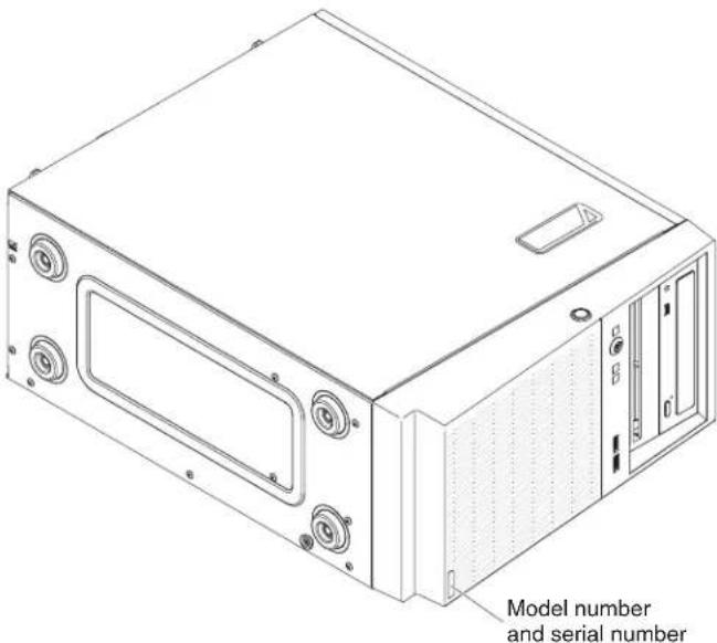
Figure73.IDlabelofthe4Uservermodelwithnon-hot-swappowersupplies

Figure74. IDlabelofthe5Usermodelwithnon-hot-swappowersupplies
•Machinetypeandmodel
•Microprocessororharddiskdriveupgrades
•Failuresymptom
-Doestheserverfailthediagnostictests?
-Whatoccurs?When?Where?
-Doesthefailureoccuronasingleserveroronmultipleservers?
-Isthefailurerepeatable?
-Hasthisconfigurationeverworked?
-Whatchanges,ifany,weremadebeforetheconfigurationfailed?
-Isthistheoriginalreportedfailure?
•Diagnosticprogramtypeandversionlevel
•Hardwareconfiguration(printscreenofthesystemsummary)
•UEFIfirmwarelevel
•IMMfirmwarelevel
•Operatingsystemsoftware
Youcansolvesomeproblemsbycomparingtheconfigurationandsoftwaresetups betweenworkingandnonworkingservers.Whenyoucompareserverstoeach otherfordiagnosticpurposes,considerthemidenticalonlyifallthefollowing factorsareexactlythesameinalltheservers:
•Machinetypeandmodel
•UEFIfirmwarelevel
•IMMfirmwarelevel
•Adaptersandattachments,inthesamelocations
- Addressjumpers,terminators,andcabling
•Softwareversionsandlevels
•Diagnosticprogramtypeandversionlevel
-Configurationoptionsettings
- Operating-systemcontrol-filesetup
See AppendixD, "Gettinghelpandtechnicalassistance," onpage651 for informationaboutcallingIBMforservice.
Recoveringtheserverfirmware(UEFlupdatefailure)
Usethisinformationtorecovertheserverfirmware.
Important: Some clusters solutions requires specific code levels or coordinated code updates. If the device is part of clusters solution, verify that the latest level of code is supported for the clusters solution before you update the decode.
If the server firmware has become corrupted, such as from a power failure during an update, you can recover the server firmware in the following way:
- In-band method: Recover server firmware, using either the boot block jumper (AutomatedBootRecovery) and aserverFirmwareUpdatePackageService Pack.
- Out-of-band method: Use the IMM web interface to update the firmware, using the latest server firmware update package.
Note: You can obtain a server update package from one of the following sources:
- DownloadtheserverfirmwareupdatefromtheWorldWideWeb.
- ContactyourIBMservicerepresentative.
TodownloadtheserverfirmwareupdatepackagefromtheWorldWideWeb,goto http://www.ibm.com/supportporta.
Theflashmemoryoftheserverconsistsofaprimarybankandabackupbank. You mustmaintainabootableUEFIfirmwareimageinthebackupbank.Iftheserver firmwareintheprimarybankbecomescorrupted,youcaneithermanuallyboot thebackupbankwiththeUEFIbootbackupjumper(JP2),orinthecaseofimage corruption,thiswilloccurautomaticallywiththeAutomatedBootRecovery function.
In-bandmanualrecoverymethod
Thissectiondetailsthein-bandmanualrecoverymethod.
Aboutthistask
Torecovertheserverfirmwareandrestoretheserveroperationtotheprimary bank,completethefollowingsteps:
Procedure
- Readthesafetyinformationthatbeginson"Safety"onpageviiand "Installationguidelines"onpage35.
- Turnofftheserver, and disconnectallpowercordsandexternalcables.
- Unlockandremovethesidecover(see "Removingthesidecover" on page 38).
- LocatetheUEFlbootbackupjumperonthesystemboard.
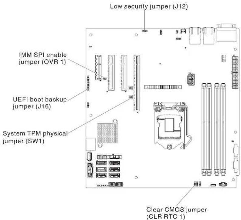
Figure75.Locationoftheswitches,jumpers,andbuttonsonthesystemboard
-
MovetheUEFIbootbackupjumperfrompins1and2topins2and3to enabletheUEFIrecoverymode.
-
Reinstalltheservercover;then,reconnectallpowercords.
-
Restart the server. Thesystem beginsthe power-onself-test (POST).
-
Boottheservertoanoperatingsystemthatissupportedbythefirmware updatepackagethatyoudownloaded.
-
Perform the firmware update by following the instruction that are in the firmware update package read me file.
-
Turnoff the server and disconnect all power cords and external cables, and then removethesidecover (see "Removingthesidecover" on page 38).
-
MovetheUEFIbootbackupjumperfrompins2and3backtotheprimary position(pins1and2).
-
Reinstallthecover(see "Replacingthesidecover" onpage182).
-
Reconnectthepowercordandanycablesthatyouremoved.
-
Restart the server. Thesystem begins the power-on self-test (POST). If this does not recover the primary bank, continue with the following steps.
-
Removethesidecover(see"Removingthesidecover"onpage38).
-
ResettheCMOSbyremovingthesystembattery(see"Removingthesystem battery"onpage279).
-
Leavethesystembatteryoutoftheserverforapproximately5to15minutes.
-
Reinstallthesystembattery(see"Replacingthesystembattery" on page 281).
-
Reinstallthecover(see"Replacingthesidecover" onpage182).
-
Reconnectthepowercordandanycablesthatyouremoved.
-
Restarttheserver.Thesystembeginsthepower-onself-test(POST).
-
If the recovery efforts fail, contact your IBM servicerepresentative for support.
In-bandautomatedbootrecoverymethod
Thissectiondetailsthein-bandautomatedbootrecoverymethod.
Aboutthistask
Note: UsethismethodiftheSystemboardLEDonthelightpathdiagnostics panelislitandthereisalogentryorBooting Backup Image isdisplayedonthe firmwaresplashscreen; otherwise, usethein-bandmanualrecoverymethod.
Procedure
- Boottheservertoanoperatingsystemthatissupportedbythefirmware updatepackagethatyoudownloaded.
- Perform the firmware update by following the instruction that are in the firmware update package read me file.
- Restarttheserver.
- Atthefirmwaresplashscreen, pressF3 when prompted to restore the primary bank. Theserverboots from the primary bank.
Out-of-bandmethod
See the IMM2 documentation (Integrated Management Module II User's Guide) at http://www-947.ibm.com/support/entry/portal/docdisplay?lndocid=migr-5086346.
Automatedbootrecovery(ABR)
Use this information for Automated boot recovery (ABR).
Aboutthistask
While the server is starting, if the integrated management module II detects problems with the server firmware in the primary bank, the server automatically switches the backup firmware and gives you the opportunity to recover the firmware in the primary bank. For instructions for recovering the UEFI firmware,see"Recoveringtheserverfirmware(UEFlupdatefailure)"onpage161.
Afteryouhaverecoveredthefirmwareintheprimarybank,completethe followingsteps:
Procedure
- Restarttheserver.
- When the prompt Press F3 to restore to primary is displayed, press F3 to start the server from the primary bank.
Nx-bootfailure
UsethisinformationforNx-bootfailure.
Configurationchanges,suchasaddeddevicesoradapterfirmwareupdates,and firmwareorapplicationcodeproblemscancausetheservertofailPOST(the power-onself-test).Ifthisoccurs,theserverrespondsineitherofthefollowing ways:
- TheserverrestartsautomaticallyandattemptsPOSTagain.
- Theserverhangs, and you must manually restart the server for the server to attempt POSTagain.
Afteraspecifiednumberofconsecutiveattempts(automaticormanual),the Nx-bootfailurefeaturecausestheservertoreverttothedefaultUEFlconfiguration andstarttheSetuputilitysothatyoucanmakethenecessarycorrectionstothe configurationandrestarttheserver.Iftheserverisunabletosuccessfullycomplete POSTwiththedefaultconfiguration,theremightbeaproblemwiththesystem board.
TospecifythenumberofconsecutivererestartattemptsthatwilltriggertheNx-boot failure feature, in the Setup utility, click System Settings > Recovery > POST Attempts > POST Attempts Limit. The available options are 3, 6, 9, and 255 (disableNx-bootfailure).
Chapter5.Partslisting,IBMSystemx3100M5Type5457
ThepartslistingofIBMSystemx3100M5Type5457.
The following replaceable components are available for the IBM System x3100M5 Type 5457 server, except a specified otherwise in "Replaceable server components." For an updated parts listing, goto http://www.ibm.com/supportportal.
Replaceableservercomponents
ThereplaceableservercomponentsforIBMSystemx3100M5Type5457.
Replaceablecomponentsconsistofstructuralparts,andfieldreplaceableunits (FRUs):
- Structural parts: Purchase and replacement of structural parts (components, such aschassisassembly,topcover,andbezel)isyourresponsibility.IfIBMacquires orinstallsastructuralcomponentatyourrequest,youwillbechargedforthe service.See"Structuralparts"onpage174forthelistofstructuralparts.
- Tier 1 customer replaceable unit (CRU): Replacement of Tier 1 CRUs is your responsibility. If IBMInstallsaTier1CRUatyourrequest, you will be charged for the installation.
- Tier 2 customer replaceable unit: You may install a Tier 2 CRU yourself or requestIBMtoinstallit,atnoadditionalcharge,underthetypeofwarranty servicethatisdesignatedforyourserver.
Forinformationaboutthetermsofthewarrantyandgettingserviceandassistance, seetheWarrantyInformationdocumentthatcomeswiththeserver.Formore informationaboutgettingserviceandassistance,seeAppendixD,"Gettinghelp andtechnicalassistance,"onpage651.
Visit http://www.ibm.com/systems/info/x86servers/serverproven/compat/usfor thelatestoptionssupportingplan.
The following illustrations show sthemajor components in 4User models with non-hot-swappowers supplies. The illustrations in this document might differ slightly from your hardware. For the 5User model with hot-swappower supplies, please seethetable below.
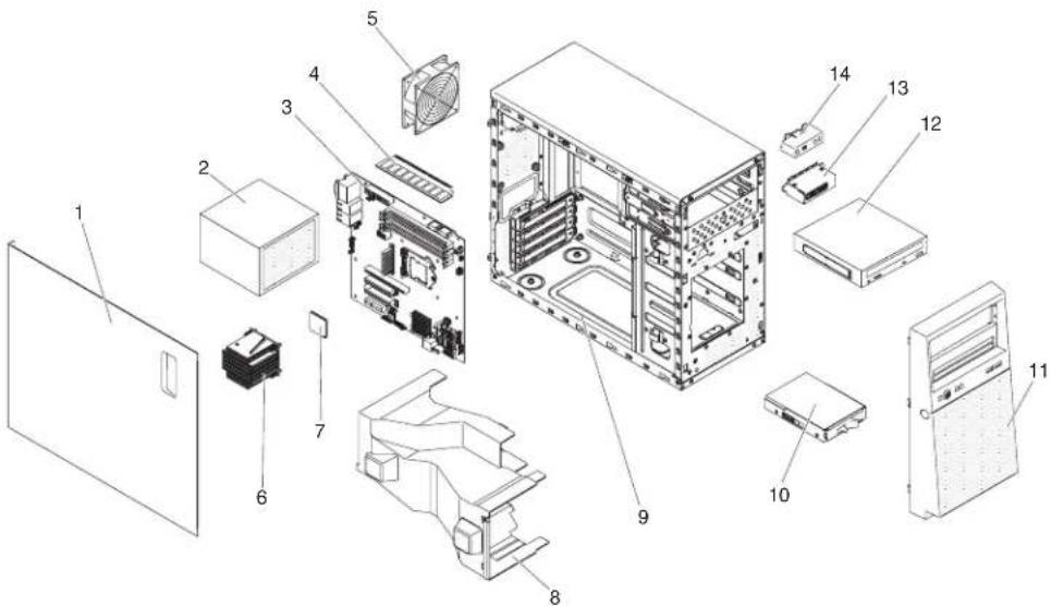
Figure76.Servercomponentsfor4Uservermodelwithnon-hot-swappowersupplies
The following table lists the part numbers for the server replaceable components.
Table30. Partslisting, 4Uservermodelwithnon-hot-swappowersupplies
| Index number | Descriptionofservercomponent | CRUpart number(Tier1) | CRUpart number(Tier2) |
| 2Powersupply,300W,fixed00AL206 | |||
| 2Powersupply,350W,fixed00AL205 | |||
| 3Systemboard46W9038 | |||
| 4Memory,4GB2Rx8UDIMM,1600MHz,DDR300D5014 | |||
| 4Memory,8GB2Rx8UDIMM,1600MHz,DDR300D5018 | |||
| 5Systemfan,rear00AL089 | |||
| 6Heatsink00Y8238 | |||
| 7Microprocessor,IntelCore-i34360,3.7GHz,4MB,1600MHz,54W (2-core) | 00KA424 | ||
| 7Microprocessor,IntelCore-i34350,3.6GHz,4MB,1600MHz,54W (2-core) | 00KA425 | ||
| 7Microprocessor,IntelCore-i34150,3.5GHz,3MB,1600MHz,54W (2-core) | 00KA427 | ||
| 7Microprocessor,IntelCore-i34150T,3.0GHz,3MB,1600MHz,35W (2-core) | 00KA428 | ||
| 7Microprocessor,IntelPentiumG3450,3.4GHz,3MB,1600MHz,54 W(2-core) | 00KA429 | ||
| 7Microprocessor,IntelPentiumG3240,3.1GHz,3MB,1600MHz,54 W(2-core) | 00KA431 | ||
| 7Microprocessor,IntelPentiumG3240T,2.7GHz,3MB,1600MHz,35 W(2-core) | 00KA432 | ||
| 7Microprocessor,IntelCeleronG1840,2.8GHz,2MB,1600MHz,54 W(2-core) | 00KA434 | ||
| 7Microprocessor,IntelPentiumG3440,3.3GHz,3MB,1600MHz,54 W(2-core) | 00KA450 | ||
| 7Microprocessor,IntelXeonE3-1231v3,3.4GHz,8MB,1600MHz,80 W(4-core) | 00KA451 | ||
| 7Microprocessor,IntelXeonE3-1241v3,3.5GHz,8MB,1600MHz,80 W(4-core) | 00KA452 | ||
| 7Microprocessor,IntelXeonE3-1271v3,3.6GHz,8MB,1600MHz,80 W(4-core) | 00KA453 | ||
| 7Microprocessor,IntelXeonE3-1281v3,3.7GHz,8MB,1600MHz,95 W(4-core) | 00KA454 | ||
| 7Microprocessor,IntelXeonE3-1275Lv3,2.7GHz,8MB,1600MHz, 45W(4-core) | 00KA455 | ||
| 7Microprocessor,IntelXeonE3-1240Lv3,2.0GHz,8MB,1600MHz, 25W(4-core) | 00KA456 | ||
| 7Microprocessor,IntelXeonE3-1220v3,3.1GHz,8MB,1600MHz,80 W(4-core) | 00Y8235 | ||
| 7Microprocessor,IntelXeonE3-1220Lv3,1.1GHz,4MBcache,1600 MHz,13W(2-core) | 00AM097 | ||
| 10DVD-ROMDrive43W8466 | |||
| 10DVD MultiburnerDrive43W8467 | |||
| 11Hard diskdrive,3.5-inchsimple-swap,500GB,7.2K81Y9803 | |||
| 11Hard diskdrive,3.5-inchsimple-swap,1TB,7.2K81Y9807 | |||
| 11Hard diskdrive,3.5-inchsimple-swap,2TB,7.2K81Y9811 | |||
| 11Hard diskdrive,3.5-inchsimple-swap,3TB,7.2K81Y9815 | |||
| 13Front USBconnectorholderfor4Uchassis00AL691 | |||
| 14Operatorinformationpanelassembly00KA584 | |||
| Thermalsensorkit46W9221 | |||
| Battery,3.0volt33F8354 | |||
| Cable,SAS680Rcable | 00D2814 | ||
| Cable,SAS700mmcable | 00D2817 | ||
| Cable,USBfor4Uchassis | 00Y8282 | ||
| Cable,3.5"SATA | 00Y8279 | ||
| Cable,3.5"backplanesignalcable | 46W9217 | ||
| Cable,2.5"backplanesignalcable | 46W9218 | ||
| Cable,24-inchSATA | 25R5635 | ||
| Cable,1M | 39R6530 | ||
| Cable,3M | 39R6532 | ||
| Cable,SASY-cable | 44E8878 | ||
| Cable,USB1m | 44E8893 | ||
| Cable,USBdongle | 44E8894 | ||
| Cable,powersupplyinterposer | 00D8861 | ||
| Cable,powersupplyinterposer | 00D2749 | ||
| Cable,USBconversion | 39M2909 | ||
| Cable,USB | 46M6475 | ||
| Cable,USB46M6477 | |||
| Cable,USB81Y3643 | |||
| Cord,4-4.3Mline39M5076 | |||
| Cord,1.5Mline39M5375 | |||
| Cord,4.3Mline39M5378 | |||
| Cord,PDUjumper30M5392 | |||
| Cord,PDUC1960A3Pwithline39Y8926 | |||
| Cord,C13PDUwithoutline46W1588 | |||
| Retentionbracket(front),adapter13N2993 | |||
| ServeRAIDM1115SAS/SATAController46C8928 | |||
| ServeRAIDH1110SAS/SATAController81Y4494 | |||
| ServeRAIDM5100series512MBcache(RAID5upgrade) | 81Y4485 | ||
| ServeRAIDM5100series512MBflash(RAID5upgrade) | 46C9027 | ||
| ServeRAIDM5110SAS/SATAController | 00AE807 | ||
| ServeRAIDM5120SAS/SATAController | 00AE811 | ||
| 6GbSAShostbusadapter(HBA) | 46C8935 | ||
| N2115SAS/SATAHBA | 46C8989 | ||
| N2125SAS/SATAHBA | 46C9011 | ||
| 10GbSFP+SRopticaltransceiver | 46C9297 | ||
| Brocade8GbFCsingle-porthostbusadapter | 46M6061 | ||
| Brocade8GbFCdual-porthostbusadapter | 46M6062 | ||
| Brocade16GbFCsingle-portHBA | 81Y1671 | ||
| Brocade16GbFCdual-portHBA | 81Y1678 | ||
| BroadcomNetXtremeIIdual-port10Gbadapter | 49Y7912 | ||
| BroadcomNetXtremeIdual-portGbEadapter | 90Y9373 | ||
| BroadcomNetXtremelquad-portGbEadapter | 90Y9355 | ||
| IntelX520-DA2dual-port10Gbvirtualfabricadapter | 49Y7962 | ||
| IntelX540-T2dual-port10GbBaseTAdapter | 49Y7972 | ||
| Intell340-T2Ethernetdual-portadapter | 94Y5166 | ||
| Intell340-T4Ethernetquad-portadapter | 94Y5167 | ||
| IntelPRO/1000PFserveradapter | 42C1752 | ||
| QLogic8200dual-port10GbSFP+VFAadapter | 90Y4605 | ||
| Emulex10GbEvirtualfabricadapterIII95Y3766 | |||
| MellanoxConnectX-310GbEadapter | 00D9692 | ||
| Videoadapter,NVIDIAQuadroK600 | 90Y2383 | ||
| QLogic16GbFCSingle-portHBA | 00Y3340 | ||
| QLogic16GbFCDual-portHBA | 00Y3344 | ||
| QLogic8GbFCSingle-portHBA | 00Y5628 | ||
| QLogic8GbFCDual-portHBA | 00Y5629 | ||
| Index numberD | descriptionofservercomponent | CRUpart number(Tier1) | CRUpart number(Tier2) |
| Emulex8GbFCSingle-portHBA42D0491 | |||
| Emulex8GbFCDual-portHBA42D0500 | |||
| Emulex16GbFCDual-portHBA00D8548 | |||
| QLogic10GbvirtualfabricandSRopticaltransceiver42C1816 | |||
| InternalUSB3RDXcarrier/dock46C2346 | |||
| InternalUSBRDXcarrier/dock46C5380 | |||
| RDX320GBcartridge46C5394 | |||
| RDX500GBcartridge46C5395 | |||
| RSPDU+24C1330A46W1562 | |||
| RSPDU24C133P46W1568 | |||
| RSPDU24C131P46W1570 | |||
| RSPDU+12C19/146W1574 | |||
| RSPDU12C19/12 | 46W1578 | ||
| RPDU+9C19/3C1 | 46W1582 | ||
| 60A3PhasePDU | 46W1612 | ||
| 60A3PhasePDU | 46W1614 | ||
| NEMAPDU | 39Y8913 | ||
| IECRackPDU | 39Y8914 | ||
| DPIFEPDU | 39Y8916 | ||
| HalfhighLTOGen4SASTapedrive | 46X5672 | ||
| HalfhighLTOGen5SASTapedrive | 46X5683 | ||
| Drive,5.25-inch,80GB,USB | 99Y3870 | ||
| Mouse,USB | 39Y9875 | ||
| Thermalsolutionfankitfor4Uchassis | 00AL719 | ||
| USBcableholderfor4Uchassis | 00AL691 | ||
| Operatingtemperatureenhancementkitfor4Uchassis | 00AL720 | ||
| 3.5"simple-swaphardwareRAIDupgradekit | 00Y8280 | ||
| Miscellaneoushardware | 00AL703 |
Consumable parts (parts that are purchased separately) are not covered by the IBM Statement of Limited Warranty. The following consumable parts are available for purchase from the retailstore.
| Index | Description | Partnumber |
| Battery,ServeRAID-M5100 series | 81Y4491 |
The following illustration shows the major components in the 5U server model with hot-swap power supplies. The illustrations in this document might differ slightly from your hardware. For 4U server models with non-hot-swap power
supplies,pleaseseethetableabove.
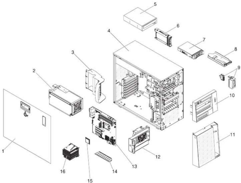
Figure77.Servercomponentsfor5Usermodelwithhot-swappowersupplies
Table31. Partslisting, 5Uservermodelwithhot-swappowersupplies
| Index numberD | descriptionofservercomponent | CRUpart number(Tier1) | CRUpart number(Tier2) |
| 2Powersupply, redundant, 430watt00AL204 | |||
| 5DVD-ROMDrive43W8466 | |||
| 5DVD MultiburnerDrive43W8467 | |||
| 6Hard diskdrive, 2.5-inchhot-swap, 900GB, 10K81Y9651 | |||
| 6Hard diskdrive, 2.5-inchhot-swap, 900GB, 10K, SED81Y9663 | |||
| 6Hard diskdrive, 2.5-inchhot-swap, 300GB, 15K81Y9671 | |||
| 6Hard diskdrive, 2.5-inchhot-swap, 1TB, 7.2K81Y9691 | |||
| 6Hard diskdrive, 2.5-inchhot-swap, 250GB, 7.2K81Y9735 | |||
| 6Hard diskdrive, 2.5-inchhot-swap, 500GB, 7.2K81Y9739 | |||
| 6Hard diskdrive, 2.5-inchhot-swap, 1TB, 7.2K81Y9743 | |||
| 6Solid statedrive, 2.5-inchsimple-swap, SATA, 256GB90Y8664 | |||
| 6Hard diskdrive, 2.5-inchhot-swap, 600GB, 10K90Y8873 | |||
| 6Hard diskdrive, 2.5-inchhot-swap, 300GB, 10K90Y8878 | |||
| 6Hard diskdrive, 2.5-inchhot-swap, 600GB, 10K, SED90Y8909 | |||
| 6Hard diskdrive, 2.5-inchhot-swap, 146GB, 15K90Y8927 | |||
| 6Hard diskdrive, 2.5-inchhot-swap, 500GB, 7.2K90Y8954 | |||
| 6Hard diskdrive, 2.5-inchhot-swap, 500GB, 7.2K | 42D0708 | ||
| Index number | Descriptionofservercomponent | CRUpart number(Tier1) | CRUpart number(Tier2) |
| 7Hard | diskdrive,3.5-inchhot-swap,300GB,15K49Y6093 | ||
| 7Hard | diskdrive,3.5-inchhot-swap,450GB,15K49Y6098 | ||
| 7Hard | diskdrive,3.5-inchhot-swap,600GB,15K49Y6103 | ||
| 7Hard | diskdrive,3.5-inchhot-swap,500GB,7.2K81Y9787 | ||
| 7Hard | diskdrive,3.5-inchhot-swap,1TB,7.2K81Y9791 | ||
| 7Hard | diskdrive,3.5-inchhot-swap,2TB,7.2K81Y9795 | ||
| 7Hard | diskdrive,3.5-inchhot-swap,3TB,7.2K81Y9799 | ||
| 8Operatorinformationpanelassembly49Y8456 | |||
| 9Front | USBconnectorholderfor5Uchassis00AL692 | ||
| 122.5"harddiskdrivefanduct00AL088 | |||
| 123.5"harddiskdrivefanduct00AL684 | |||
| 13Systemboard46W9038 | |||
| 14Memory,4GB2Rx8UDIMM,1600MHz,DDR300D5014 | |||
| 14Memory,8GB2Rx8UDIMM,1600MHz,DDR300D5018 | |||
| 15Microprocessor,IntelCore-i34360,3.7GHz,4MB,1600MHz,54W(2-core) | 00KA424 | ||
| 15Microprocessor,IntelCore-i34350,3.6GHz,4MB,1600MHz,54W(2-core) | 00KA425 | ||
| 15Microprocessor,IntelCore-i34150,3.5GHz,3MB,1600MHz,54W(2-core) | 00KA427 | ||
| 15Microprocessor,IntelCore-i34150T,3.0GHz,3MB,1600MHz,35W(2-core) | 00KA428 | ||
| 15Microprocessor,IntelPentiumG3450,3.4GHz,3MB,1600MHz,54W(2-core) | 00KA429 | ||
| 15Microprocessor,IntelPentiumG3240,3.1GHz,3MB,1600MHz,54W(2-core) | 00KA431 | ||
| 15Microprocessor,IntelPentiumG3240T,2.7GHz,3MB,1600MHz,35W(2-core) | 00KA432 | ||
| 15Microprocessor,IntelCeleronG1840,2.8GHz,2MB,1600MHz,54W(2-core) | 00KA434 | ||
| 15Microprocessor,IntelPentiumG3440,3.3GHz,3MB,1600MHz,54W(2-core) | 00KA450 | ||
| 15Microprocessor,IntelXeonE3-1231v3,3.4GHz,8MB,1600MHz,80W(4-core) | 00KA451 | ||
| 15Microprocessor,IntelXeonE3-1241v3,3.5GHz,8MB,1600MHz,80W(4-core) | 00KA452 | ||
| 15Microprocessor,IntelXeonE3-1271v3,3.6GHz,8MB,1600MHz,80W(4-core) | 00KA453 | ||
| 15Microprocessor,IntelXeonE3-1281v3,3.7GHz,8MB,1600MHz,95W(4-core) | 00KA454 | ||
| 15Microprocessor,IntelXeonE3-1275Lv3,2.7GHz,8MB,1600MHz,45W(4-core) | 00KA455 | ||
| 15Microprocessor,IntelXeonE3-1240Lv3,2.0GHz,8MB,1600MHz,25W(4-core) | 00KA456 | ||
| 15Microprocessor,IntelXeonE3-1220v3,3.1GHz,8MB,1600MHz,80W(4-core) | 00Y8235 | ||
| 15Microprocessor,IntelXeonE3-1220Lv3,1.1GHz,4MBcache,1600MHz,13W(2-core) | 00AM097 | ||
| 16Heatsink00Y8238 | |||
| Thermalsensorkit46W9221 | |||
| Battery,3.0volt33F8354 | |||
| Cable,SAS680Rcable00D2814 | |||
| Cable,SAS700mmcable00D2817 | |||
| Cable,USBfor5Uchassis00KA532 | |||
| Cable,3.5"SATA00Y8279 | |||
| Cable,3.5"backplanesignalcable46W9217 | |||
| Cable,2.5"backplanesignalcable46W9218 | |||
| Cable,24-inchSATA25R5635 | |||
| Cable,1M | 39R6530 | ||
| Cable,3M | 39R6532 | ||
| Cable,SASY-cable | 44E8878 | ||
| Cable,USB1m | 44E8893 | ||
| Cable,USBdongle | 44E8894 | ||
| Cable,powersupplyinterposer | 00D8861 | ||
| Cable,powersupplyinterposer | 00D2749 | ||
| Cable,USBconversion | 39M2909 | ||
| Cable,USB | 46M6475 | ||
| Cable,USB | 46M6477 | ||
| Cable,USB | 81Y3643 | ||
| Cord,4-4.3Mline | 39M5076 | ||
| Cord,1.5Mline | 39M5375 | ||
| Cord,4.3Mline | 39M5378 | ||
| Cord,PDUjumper | 30M5392 | ||
| Cord,PDUC1960A3Pwithline | 39Y8926 | ||
| Cord,C13PDUwithoutline | 46W1588 | ||
| Retentionbracket(front),adapter | 13N2993 | ||
| ServeRAIDM1115SAS/SATAController | 46C8928 | ||
| ServeRAIDH1110SAS/SATAController | 81Y4494 | ||
| ServeRAIDM5100series512MBcache(RAID5upgrade) | 81Y4485 | ||
| ServeRAIDM5100series512MBflash(RAID5upgrade) | 46C9027 | ||
| ServeRAIDM5110SAS/SATAController | 00AE807 | ||
| ServeRAIDM5120SAS/SATAController | 00AE811 | ||
| 6GbSAShostbusadapter(HBA) | 46C8935 | ||
| N2115SAS/SATAHBA | 46C8989 | ||
| N2125SAS/SATAHBA46C9011 | |||
| 10GbSFP+SRopticaltransceiver46C9297 | |||
| Brocade8GbFCsingle-porthostbusadapter46M6061 | |||
| Brocade8GbFCdual-porthostbusadapter46M6062 | |||
| Brocade16GbFCsingle-portHBA81Y1671 | |||
| Brocade16GbFCdual-portHBA81Y1678 | |||
| BroadcomNetXtremeIIdual-port10Gbadapter49Y7912 | |||
| BroadcomNetXtremeldual-portGbEadapter90Y9373 | |||
| BroadcomNetXtremeIquad-portGbEadapter90Y9355 | |||
| IntelX520-DA2dual-port10Gbvirtualfabricadapter49Y7962 | |||
| IntelX540-T2dual-port10GbBaseTAdapter | 49Y7972 | ||
| IntelI340-T2Ethernetdual-portadapter | 94Y5166 | ||
| IntelI340-T4Ethernetquad-portadapter | 94Y5167 | ||
| IntelPRO/1000PFserveradapter42C1752 | |||
| QLogic8200dual-port10GbSFP+VFAadapter | 90Y4605 | ||
| Emulex10GbEvirtualfabricadapterIII | 95Y3766 | ||
| MellanoxConnectX-310GbEadapter | 00D9692 | ||
| Videoadapter,NVIDIAQuadroK600 | 90Y2383 | ||
| QLogic16GbFCSingle-portHBA | 00Y3340 | ||
| QLogic16GbFCDual-portHBA | 00Y3344 | ||
| QLogic8GbFCSingle-portHBA | 00Y5628 | ||
| QLogic8GbFCDual-portHBA | 00Y5629 | ||
| Emulex8GbFCSingle-portHBA | 42D0491 | ||
| Emulex8GbFCDual-portHBA | 42D0500 | ||
| Emulex16GbFCDual-portHBA00D8548 | |||
| QLogic10GbvirtualfabricandSRopticaltransceiver | 42C1816 | ||
| Powersupplycage,430watt | 49Y8459 | ||
| 2.5-inchhot-swapharddiskdriveCR2backplane | 46W9187 | ||
| 3.5-inchhot-swapharddiskdrivebackplane | 49Y4462 | ||
| InternalUSB3RDXcarrier/dock | 46C2346 | ||
| InternalUSBRDXcarrier/dock | 46C5380 | ||
| RDX320GBcartridge | 46C5394 | ||
| RDX500GBcartridge | 46C5395 | ||
| RSPDU+24C1330A | 46W1562 | ||
| RSPDU24C133P | 46W1568 | ||
| RSPDU24C131P | 46W1570 | ||
| RSPDU+12C19/1 | 46W1574 | ||
| RSPDU12C19/12 | 46W1578 | ||
| RPDU+9C19/3C1 | 46W1582 | ||
| Index numberD | Descriptionofservercomponent | CRUpart number(Tier1) | CRUpart number(Tier2) |
| 60A3PhasePDU46W1612 | |||
| 60A3PhasePDU46W1614 | |||
| NEMAPDU39Y8913 | |||
| IECRackPDU39Y8914 | |||
| DPIFEPDU39Y8916 | |||
| HalfhighLTOGen4SASTapedrive46X5672 | |||
| HalfhighLTOGen5SASTapedrive46X5683 | |||
| Drive,5.25-inch,80GB,USB99Y3870 | |||
| Mouse,USB39Y9875 | |||
| Thermalsolutionfankitfor5Uchassis00AL001 | |||
| USBcableholderfor5Uchassis00AL692 | |||
| Operatingtemperatureenhancementkitfor5Uchassis00AL721 | |||
| Miscellaneoushardware | 00AL703 | ||
Consumable parts (parts that are purchased separately) are not covered by the IBM Statement of Limited Warranty. The following consumable parts are available for purchase from the retailstore.
| Index | Description | Partnumber |
| Battery,ServeRAID-M5100 series | 81Y4491 |
Structural parts
Structural parts are not covered by the IBM Statement of Limited Warranty. You can place an order on the structural parts from the IBM retail store.
The following structural parts are for 4U server models with non-hot-swap power supplies. They are available for purchase from the retail store.
Table32. Structuralpartsfor4Uservermodelswithnon-hot-swappowersupplies, Type5457
| Index | Description | Partnumber |
| 1 | Sidecoverassembly | 00AL701 |
| 8 | Airbaffle | 00AL109 |
| 9 | 4Uchassisassembly | 00AL700 |
| 12 | Bezel | 13N2450 |
| 12 | Bezel | 00AL690 |
| Simple-swapharddiskdrivecage,3.5"drives | 00AL689 | |
| Filler,powersupply | 00D8860 | |
| Filler,DVD-ROMDrive | 13N2450 | |
| Feet,chassis | 13N2985 | |
| EMCshieldkit,opticaldiskdrive/tapedrive | 13N2997 | |
| Kit,Retainer(foropticalanddiskettedrives) | 39R9369 | |
| IndexDescription | Partnumber | |
| EMCshield49Y8455 | ||
| Filler,PCIcard81Y7472 | ||
| DVDdriveretentionbracketfor4Uchassis81Y7473 | ||
| PCIadapterretentionbracketfor4Uchassis81Y7474 | ||
| Shieldkit,simple-swap3.5-inchharddiskdrive81Y7479 | ||
| Chassisstandfootassembly81Y7483 | ||
| Miscellaneoushardwareforrack00N7193 | ||
| Rackkitassembly00Y7580 | ||
| Holder,battery(retainer)00Y8545 | ||
| Bottomcover | 39R9363 | |
| Rackchassis | 39Y9760 | |
| Cablemanagementarm | 39Y9761 | |
| Miscellaneoushardware | 39Y9837 | |
| Screw,fourM3x5screws | 42C3933 | |
| Frictionslide | 69Y4391 | |
| RemoteRAIDbattery/powermoduletray | 94Y7609 | |
| 3UBRACKETKIT | 94Y7628 | |
| EIAbrackets | 39Y9758 | |
| Side/topcover49Y8446 |
The following structural parts are for 5U server models with hot-swap power supplies. They are available for purchase from the retail store.
Table33. Structuralpartsfor5Uservermodelswithhot-swappowersupplies, Type5457
| IndexDescription | Partnumber | |
| 1 | Sidecoverwithlock | 49Y8447 |
| 3 | Retentionbracket(rear)for5Uchassis,adapter | 00AL013 |
| 4 | 5Uchassisassembly | 00AL688 |
| 10 | Bezel,upper | 00AL687 |
| 11 | Bezel,lower(for3.5"harddiskdrives) | 00AL693 |
| 11 | Bezel,lower(for2.5"harddiskdrives) | 90Y5210 |
| Harddiskdrivecage,3.5" drives | 00AL685 | |
| Harddiskdrivecage,2.5" drives | 00D8852 | |
| Filler,powersupply | 00D8860 | |
| Filler,DVD-ROMDrive | 13N2450 | |
| Feet,chassis | 13N2985 | |
| EMCshieldkit,opticaldiskdrive/tapedrive | 13N2997 | |
| Keylock,keyed-random | 26K7364 | |
| Kit,Retainer(foropticalanddiskettedrives) | 39R9369 | |
| EMCshield49Y8455 | ||
| Filler,PCIcard81Y7472 | ||
| Chassisstandfootassembly81Y7483 | ||
| Miscellaneoushardwareforrack00N7193 | ||
| Rackkitassembly00Y7580 | ||
| Holder,battery(retainer)00Y8545 | ||
| Bottomcover39R9363 | ||
| Rackchassis39Y9760 | ||
| Cablemanagementarm39Y9761 | ||
| Miscellaneoushardware39Y9837 | ||
| Screw,fourM3x5screws42C3933 | ||
| Towertorackslidekitfor5Uchassis | 42R5348 | |
| HardwareRAIDbatteryholderfor5Uchassis | 00AL722 | |
| Frictionslide | 69Y4391 | |
| RemoteRAIDbattery/powermoduletray | 94Y7609 | |
| 3UBRACKETKIT | 94Y7628 | |
| EIAbrackets | 39Y9758 | |
| Keylockassembly | 26K7363 | |
| Side/topcover | 49Y8446 |
To order a structural part, complete the following steps:
Note: Changes are made periodically to the IBM website. The actual procedure might vary slightly from what is described in this document.
-
Go to http://www.ibm.com.
-
From the Products menu, select Upgrades, accessories & parts.
-
Click Obtain maintenance parts; then, follow the instructions to order the part from the retailstore.
If you need help with your order, call the toll-free number that is listed on the retail parts page, or contact your local IBM representative for assistance.
Power cords
For your safety, a power cord with a grounded attachment plug is provided to use with this product. To avoid electrical shock, always use the power cord and plug with a properly grounded outlet.
IBM power cords used in the United States and Canada are listed by Underwriter's Laboratories (UL) and certified by the Canadian Standards Association (CSA).
For units intended to be operated at 115 volts: Use a UL-listed and CSA-certified cord set consisting of a minimum 18 AWG, Type SVT or SJT, three-conductor cord, a maximum of 15 feet in length and a parallel blade, grounding-type attachment plug rated 15 amperes, 125 volts.
For units intended to be operated at 230 volts (U.S. use): Use a UL-listed and CSA-certified cord set consisting of a minimum 18 AWG, Type SVT or SJT,
three-conductorcord, a maximum of 15 feet in length and at an end of blade, grounding-type attachment plugrated 15 amperes, 250 volts.
For units intended to be operated at 230 volts (outside the U.S.): Use acordset with grounding-type attachment plug. The cordset should have the appropriate safety approvals for the country in which the equipment will be installed.
Powercordsforaspecificcountryorregionareusuallyavailableonlyinthat countryorregion.
| PowercordpartnumberUsedinthe | esecountriesandregions |
| 39M5206China | |
| 39M5102Australia,Fiji,Kiribati,Nauru,NewZealand,PapuaNewGuinea | |
| 39M5123Afghanistan,Albania,Algeria,Andorra,Angola,Armenia,Austria,Azerbaijan,Belarus,Belgium,Benin,BosniaandHerzegovina,Bulgaria,BurkinaFaso,Burundi,Cambodia,Cameroon,CapeVerde,CentralAfricanRepublic,Chad,Comoros,Congo(DemocraticRepublicof),Congo(Republicof),CoteD'Ivoire(IvoryCoast),Croatia(Republicof),CzechRepublic,Dahomey,Djibouti,Egypt,EquatorialGuinea,Eritrea,Estonia,Ethiopia,Finland,France,FrenchGuyana,FrenchPolynesia,Germany,Greece,Guadeloupe,Guinea,GuineaBissau,Hungary,Iceland,Indonesia,Iran,Kazakhstan,Kyrgyzstan,Laos(People'sDemocraticRepublicof),Latvia,Lebanon,Lithuania,Luxembourg,Macedonia(formerYugoslavRepublicof),Madagascar,Mali,Martinique,Mauritania,Mauritius,Mayotte,Moldova(Republicof),Monaco,Mongolia,Morocco,Mozambique,Netherlands,NewCaledonia,Niger,Norway,Poland,Portugal,Reunion,Romania,RussianFederation,Rwanda,SaoTomeandPrincipe,SaudiArabia,Senegal,Serbia,Slovakia,Slovenia(Republicof),Somalia,Spain,Suriname,Sweden,SyrianArabRepublic,Tajikistan,Tahiti,Togo,Tunisia,Turkey,Turkmenistan,Ukraine,UpperVolta,Uzbekistan,Vanuatu,Vietnam,WallisandFutuna,Yugoslavia(FederalRepublicof),Zaire | |
| 39M513039M5179 | Denmark |
| 39M5144Bangladesh,Lesotho,Macao,Maldives,Namibia,Nepal,Pakistan,Samoa,SouthAfrica,SriLanka,Swaziland,Uganda | |
| 39M5151AbuDhabi,Bahrain,Botswana,BruneiDarussalam,ChannelIslands,China(HongKongS.A.R.),Cyprus,Dominica,Gambia,Ghana,Grenada,Iraq,Ireland,Jordan,Kenya,Kuwait,Liberia,Malawi,Malaysia,Malta,Myanmar(Burma),Nigeria,Oman,Polynesia,Qatar,SaintKittsandNevis,SaintLucia,SaintVincentandtheGrenadines,Seychelles,SierraLeone,Singapore,Sudan,Tanzania(UnitedRepublicof),TrinidadandTobago,UnitedArabEmirates(Dubai),UnitedKingdom,Yemen,Zambia,Zimbabwe | |
| 39M5158Liechtenstein,Switzerland | |
| 39M5165Chile,Italy,LibyanArabjamahiriya | |
| 39M5172Israel | |
| 39M5095220-240V | AntiguaandBarbuda,Aruba,Bahamas,Barbados,Belize,Bermuda,Bolivia,CaicosIslands,Canada,CaymanIslands,Colombia,CostaRica,Cuba,DominicanRepublic,Ecuador,ElSalvador,Guam,Guatemala,Haiti,Honduras,Jamaica,Mexico,Micronesia(FederalStatesof),NetherlandsAntilles,Nicaragua,Panama,Peru,Philippines,SaudiArabia,Thailand,Taiwan,UnitedStatesofAmerica,Venezuela |
| 39M5081110-120V | AntiguaandBarbuda,Aruba,Bahamas,Barbados,Belize,Bermuda,Bolivia,Caicos Islands,Canada,CaymanIslands,Colombia,Costa Rica,Cuba,Dominican Republic,Ecuador,ElSalvador,Guam,Guatemala,Haiti,Honduras,Jamaica, Mexico,Micronesia(Federal States of),Netherlands Antilles,Nicaragua,Panama, Peru,Philippines,Saudi Arabia,Thailand,Taiwan,United States of America, Venezuela |
| 39M507639M5512 | United States of America |
| 39M5463Taiwan | |
| 39M5087Thailand | |
| 39M5219Korea(Democratic People's Republic of),Korea(Republic of) | |
| 39M5199Japan | |
| 39M5068Argentina,Paraguay,Uruguay | |
| 39M5226India | |
| 39M524039M5241 | Brazil |
| 39M537539M537839M5509 | Canada,Germany,United States of America |
Chapter6.Removingandreplacingcomponents
Usethisinformationtoremoveandreplacetheservercomponents.
Thetypesofreplaceablecomponentsare:
- Structural parts: Purchase and replacement of structural parts (components, such aschassisassembly,cover,andbezel)isyourresponsibility.IfIBMacquiresor installsastructuralcomponentatyourrequest,youwillbechargedforthe service.
- Tier 1 customer replaceable unit (CRU): Replacement of Tier 1 CRUs is your responsibility. If IBMInstallsaTier1CRU atyourrequest, you will be charged for the installation.
- Tier 2 customer replaceable unit (CRU): You may install a Tier 2 CRU yourself orrequestIBMtoinstallit,atnoadditionalcharge,underthetypeofwarranty servicethatisdesignatedforyourserver.
See Chapter5, "Partslisting, IBMSystemx3100M5Type5457," onpage165 to determine whether a component is a structural part, Tier1CRU, or Tier2CRU.
For information about the term so the warranty, se the Warranty Information document that comes with the server.
Formoreinformationaboutgettingserviceandassistance,seeAppendixD, "Gettinghelpandtechnicalassistance,"onpage651.
Returningadeviceorcomponent
If you are instructed to return a device or component, follow all packaging instructions, and use an y packaging materials for shipping that a resupplied to you.
Removingandreplacingservercomponents
Thissectionprovidesinformationforremovingandreplacingstructuralpartsor componentsintheserver.
Removingandreplacingstructuralparts
Thissectionprovidesinformationforremovingandreplacingstructuralpartsin theserver.
Replacementofstructuralpartsisyourresponsibility.IfIBMinstallsastructuralpartatyourrequest,youwillbechargedfortheinstallation.
Theillustrationsinthisdocumentmightdifferslightlyfromyourhardware.
Removingthesidecover
Usethisinformationtoremovethesidecover.
Attention: Operating the server form more than 30 minutes with the sidecover removed might damage server components. For proper cooling and airflow, install the sidecover before you turn on the server.
For4Uservermodelswithnon-hot-swappowersupplies,completethefollowing stepstoremovethesidecover.Forthe5Uservermodelwithhot-swappower supplies,pleaseseethenextsub-section.
- Readthesafetyinformationin"Safety"onpageviiand"Installation guidelines"onpage35.
- Turnofftheserverandperipheraldevicesanddisconnectthepowercordsandallexternalcables(see"Turningofftheserver"onpage26).
- Carefullyturntheserveronitssidesothatitislyingflat, with theoverfacing up.
Attention: Donotallowtheservertofallover.
- Unscrewthetwochassisscrewsontherearsideoftheserver.
- Pulltherearsidecoverhandleandpushthefrontsidecoverhandleatthe sametime.

Figure78.Sidecoverremovalfor4Uservermodelwithnon-hot-swappowersupplies
Attention: For proper cooling and airflow, replacetheservercover before you turnontheserver.
- If you are instructed to return the side cover, follow all packaging instructions, and use an y packaging materials for shipping that a resupplied to you.
Forthe5Uservermodelwithhot-swappowersupplies,completethefollowing stepstoremovethesidecover.For4Uservermodelswithnon-hot-swappower supplies,pleaseseetheabovesub-section.
- Readthesafetyinformationin"Safety"onpageviand"Installation guidelines"onpage35.
- Turnofftheserverandperipheraldevicesanddisconnectthepowercordsand allexternalcables(see"Turningofftheserver" onpage26).
- Unlockthesidecover; then, pressthecover-releaselatchdown (asshownin theillustration) toremovethecover.
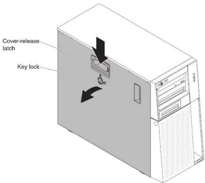
Figure79. Sidecoverremovalfor5Uservermodelwithhot-swappowersupplies
Attention: For proper cooling and airflow, replacetheservercover before you turnontheserver.
- If you are instructed to return the side cover, follow all packaging instructions, and use an y packaging materials for shipping that a resupplied to you.
Replacingthesidecover
Usethisinformationtoreplacethesidecover.
Attention: For proper cooling and airflow, replacethesidecover before returning on the server. Operating the server forextended period of time (more than 30 minutes) with the sidecover removed might damage server components.
For4Uservermodelswithnon-hot-swappowersupplies,completethefollowing stepstoremovethesidecover.Forthe5Uservermodelwithhot-swappower supplies,pleaseseethenextsub-section.
-
Readthesafetyinformationin"Safety"onpageviand"Installation guidelines"onpage35.
-
Makesurethatallcables, adapters, and other components are installed and seated correctly and that you havenot left loose tools or parts inside the server. Also, makesure that all internal cables are correctly routed.
-
Carefullyturntheserveronitssidesothatitislyingflat,withthecoverfacing up.
Attention: Donotallowtheserverterofallover.
- Pressonthesidecoverandpushfromtherearsideofthesidecoveruntil lockssecurelyintoplace.

natural_image
Illustration of a computer tower case with two downward-pointing arrows indicating compression or disassembly (no text or symbols present)Figure80.Sidecoverinstallationfor4Uservermodelwithnon-hot-swappowersupplies
- Securethesidecoverinplacewiththetwochassisscrewsontherearofthe sidecover.
- Reconnecttheexternalcablesandpowercords;then,turnontheattached devicesandturnontheserver.
Forthe5Usermodelwithhot-swappowersupplies,completethefollowing stepsinordertoremovethesidecover.For4Usermodelswithnon-hot-swap powersupplies,pleaseseetheabovesub-section.
Attention: Thecoverlockmustbeintheunlocked(opened)positionbeforeyou installthesidecover.
- Readthesafetyinformationin"Safety"onpageviand"Installation guidelines"onpage35.
- Makesurethatallcables, adapters, and other components are installed and seated correctly and that you havenot left loose tools or parts inside the server. Also, makesure that all internal cables are correctly routed.
- If you removed the upper and lower bezels, reinstall them before you replace the sidecover (see "Replacing the lower bezel" on page 190 and "Replacing the upper bezel" on page 192).
- Positionthelipatthebottomedgeofthesidecoverontheledgeatthebottom ofthechassis;then,rotatethecoveruptothechassis.Pressdownonthecover releaselatchandpushthecoverintothechassisuntillatchessecurelyinto place.
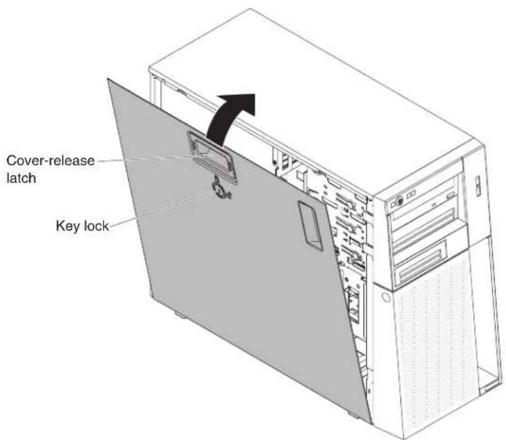
Figure81. Sidecoverinstallationfor5Uservermodelwithhot-swappowersupplies
- Lockthesidecover.
- Reconnecttheexternalcablesandpowercords;then,turnontheattached devicesandturnontheserver.
Removingtheairbaffle
Thisprocedureappliesonlyto4Uservermodelswithnon-hot-swappower supplies.
Toremovetheairbaffle,completethefollowingsteps.
- Readthesafetyinformationin"Safety"onpageviand"Installation guidelines"onpage35.
- Turnofftheserverandperipheraldevicesanddisconnectthepowercordsandallexternalcables(see"Turningofftheserver"onpage26).
- Unlockandremovethesidecover(see"Removingthesidecover" on page 38).
- Carefullyturntheserveronitssidesothatitislyingflat, with the system boardfacingup.
Attention: Donotallowtheservertofallover.
- Grasphetopoftheairbaffleandliftitoutoftheserver.

Figure82.Airbaffleremovalfor4Uservermodelwithnon-hot-swappowersupplies
Attention: For proper cooling and airflow, reinstall the airbaffle, makingsure all cables are out of the way, before you turn on the server. Operating the server with the airbaffle removed might damage server components.
- If you are instructed to return the air baffle, follow all packaging instructions, and use an y packaging materials for shipping that a resupplied to you.
Replacingtheairbaffle
Thisprocedureapplicsonlyto4Uservermodelswithnon-hot-swappower supplies.
Toinstalltheairbaffleon4Uservermodelswithnon-hot-swappowersupplies, completethefollowingsteps.
-
Readthesafetyinformationin"Safety"onpageviiand"Installation guidelines"onpage35.
-
Alignthetabsontheairbafflewiththeslotsonthechassis.
-
Lowertheairbaffleintotheserver.
Attention:
- Makenoteofthemicroprocessorpowercablerouting, asthecablemay interferewiththeairbaffleinstallation.

Figure83. Microprocessorpowercableroutingwheninstallingairbafflefor4Uservermodel withnon-hot-swappowersupplies
- Makesurethatthetabsontheairbaffleareinsertedintotheholesonthe chassisandnocablesarenotcaughtorpinched.
- Forpropercoolingandairflow,reinstalltheairbafflebeforeyouturnonthe server.Operatingtheserverwiththeairbaffleremovedmightdamageserver components.

Figure84. Airbaffle installation for 4Uservermodel with non-hot-swappowersupplies
- Installandlockthesidecover(see"Replacingthesidecover"onpage182).
- Reconnecttheexternalcablesandpowercords;then,turnontheattached devicesandturnontheserver.
Removingthebezel
Thisprocedureappliesonlyto4Uservermodelswithnon-hot-swappower supplies.
When you work with some devices on 4 User models with non-hot-swappower supplies, such as the drives in bays 3 through 6, you must first remove the bezel to access the devices.
- Readthesafetyinformationin"Safety"onpageviiand"Installation guidelines"onpage35.
- Pressthebuttonontheleftedgeofthebezel;then,rotatetheleftsideofthe bezelawayfromtheserveruntilidisengagesandsetitaside.
Note: When rotating the bezel to acertain point, it may automatically disengage from the chassis.

natural_image
Line drawing of a desktop computer tower with a blue indicator button pointing to the front panel (no text or symbols present)Figure85. Bezelremovalfor4Uservermodelwithnon-hot-swappowersupplies(1)
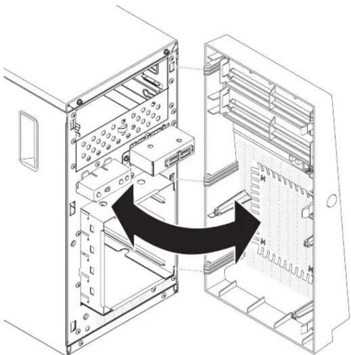
natural_image
Diagram of a computer tower internal structure showing internal components and an arrow indicating a transformation or assembly (no text or symbols present)Figure86. Bezelremovalfor4Uservermodelwithnon-hot-swappowersupplies(2)
- If you are instructed to return the bezel, follow all packaging instructions, and use anYPackaging materials for shipping that a resupplied to you.
Replacingthebezel
Thisprocedureappliesonlyto4Uservermodelswithnon-hot-swappower supplies.
Toinstallthebezelon4Uservermodelswithnon-hot-swappowersupplies, completethefollowingsteps.
- Readthesafetyinformationin"Safety"onpageviiand"Installation guidelines"onpage35.
- Insertthethreetabsonthebezelintothecorrespondingholesinthefrontof theserver.
- Rotatethebezeltotheserveruntillockssecurelyintoplace.

natural_image
Diagram of an open computer case showing internal components and a black arrow indicating a process or transformation (no text or symbols present)Figure87. Bezelinstallationfor4Uservermodelwithnon-hot-swappowersupplies
- Reconnecttheexternalcablesandpowercords;then,turnontheattached devicesandturnontheserver.
Removingthelowerbezel
Thisprocedureapppliesonlytothe5Uservermodelwithhot-swappowersupplies.
Toaccesstheharddiskdrivesonthe5Uservermodelwithhot-swappower supplies,youmustfirstremovethelowerbezel.
-
Readthesafetyinformationin"Safety"onpageviand"Installation guidelines"onpage35.
-
If you are replacing an on-hot-swap component, turn off the server and all attached devices; then, disconnect all power cords and external cables.
-
Presstheblue-coloredreleasebuttonontherightsideofthelowerbezeland rotatethelowerbezeldownwardtodisengagefromthechassis.
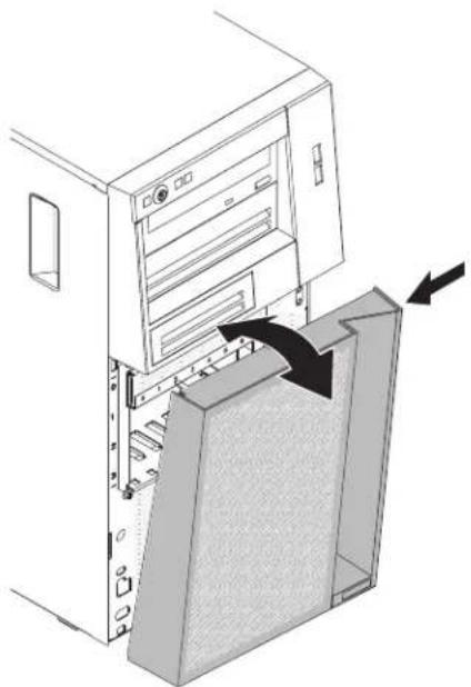
natural_image
Diagram of a computer tower with an open storage unit and a V-shaped cover, showing internal components and directional arrows (no text or symbols)Figure88. Lowerbezelremovalfor5Uservermodelwithhot-swappowersupplies
- If you are instructed to return the lower bezel, follow all packaging instructions, and use an app packaging materials for shipping that aresupplied to you.
Replacingthelowerbezel
Thisprocedureapppliesonlytothe5Uservermodelwithhot-swappowersupplies.
Toinstallthelowerbezelonthe5Uservermodelwithhot-swappowersupplies, completethefollowingsteps.
- Readthesafetyinformationin"Safety"onpageviand"Installation guidelines"onpage35.
- Insertthetwobottomtabsonthelowerbezelintothecorrespondingholesin thefrontofthechassis.

natural_image
Diagram of a computer tower with an open storage unit and a side panel, showing internal components and directional arrows (no text or symbols)Figure89. Lowerbezelinstallationfor5Uservermodelwithhot-swappowersupplies
- Rotatethetopofthelowerbezeluptothechassis;then,presstheblue-colored releasetabontherightsideofthelowerbezelandcompletelyclosethelower bezeluntilillockssecureyintoplace.
- Reconnecttheexternalcablesandpowercords;then,turnontheattached devicesandturnontheserver.
Thisprocedureapppliesonlytothe5Uservermodelwithhot-swappowersupplies.
ToaccesstheDVDdriveortapedriveonthe5Uservermodelwithhot-swap powersupplies,youmustfirstremovetheupperbezeltoaccessthedevices.
Toremovetheupperbezelonthe5Uservermodelwithhot-swappowersupplies, completethefollowingsteps.
- Readthesafetyinformationin"Safety"onpageviiand"Installation guidelines"onpage35.
- If you are replacing an on-hot-swap component, turn off the server and all attached devices; then, disconnect all power cords and external cables.
- Unlockandremovethesidecover(see"Removingthesidecover" onpage38).
- Removethelowerbezel(see"Removingthelowerbezel"onpage42).
- Carefullypullthetwobezelclipsontheleftsideoftheupperbezel;then, rotatetheupperbezeltotherightsideoftheservertodisengagethetwo right-sidetabsfromthechassis.
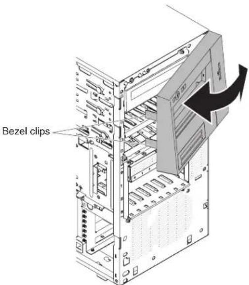
Figure90. Lowerbezelremovalfor5Uservermodelwithhot-swappowersupplies
- If you are instructed to return the upper bezel, follow all packaging instructions, and use an app packaging materials for shipping that a resupplied to you.
Thisprocedureappliesonlytothe5Uservermodelwithhot-swappowersupplies.
Toinstalltheupperbezelonthe5Uservermodelwithhot-swappowersupplies, completethefollowingsteps.
- Readthesafetyinformationin"Safety"onpageviand"Installation guidelines"onpage35.
- Insertthetwotabsontheright-sideoftheupperbezelintothecorresponding holesontherightsideofthechassis.
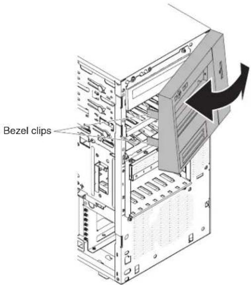
Figure91. Upperbezelinstallationfor5Uservermodelwithhot-swappowersupplies
- Rotatetheupperbezeltotheleftsideofthechassisuntilthebezelclipsare alignedwiththecorrespondingindentationsontheleftsideofthechassisand snapthemintoplace.
- Unlockandremovethesidecover(see"Replacingthelowerbezel" on page 190).
- Removethelowerbezel(see"Replacingthesidecover"onpage182).
- Reconnecttheexternalcablesandpowercords;then,turnontheattached devicesandturnontheserver.
Removingtheharddiskdrivecage
Usethisinformationtoremovetheharddiskdrivecage.
Toremovetheharddiskdrivecageon4Uservermodelswithnon-hot-swappowersupplies,completethefollowingsteps.Forthe5Uservermodelwith hot-swappowersupplies,pleaseseethenextsub-section.
-
Readthesafetyinformationin"Safety"onpageviiand"Installation guidelines"onpage35.
-
Turnoff the server and all attached devices; then, disconnect all power cords and external cables.
-
Removethebezel(see"Removingthebezel" on page 40).
-
Carefullyturntheserveronitssidesothatitislyingflat,withthecover facingup.
Attention: Donotallowtheservertertofallover.
-
Removethesidecover(see"Removingthesidecover" on page 38).
-
Removetheairbaffle(see"Removingtheairbaffle"onpage39).
-
Removethesimple-swapharddiskdrives(see"Removingasimple-swap harddiskdrive"onpage216).
-
Removethesimple-swapbackplate(see"Removingthesimple-swap backplate"onpage233).
-
Pressandholdthedrivecagereleaselatches.

Figure92. Harddiskdrivecageremovalfor4Uservermodelwithnon-hot-swappower supplies
-
Carefullypulltheharddiskdrivecageoutoftheopeninginthechassis.
-
If you are instructed to return the drive cage, follow all packaging instructions, and use an app packaging materials for shipping that aresupplied to you.
Toremovetheharddiskdrivecageon5Uservermodelswithhot-swappower supplies,completethefollowingsteps.For4Uservermodelswithnon-hot-swap powersupplies,pleaseseetheabovesub-section.
- Readthesafetyinformationin"Safety"onpageviand"Installation guidelines"onpage35.
- Turnoff the server and all attached devices; then, disconnect all power cords and external cables.
- Unlockandremovethesidecover(see"Removingthesidecover" on page 38).
- Removethelowerbezel(see"Removingthelowerbezel"onpage42).
- Removethehot-swapSAS/SATAharddiskdrivesinstalledintheharddisk drivecage(see "Removingahot-swapharddiskdrive" onpage219).
- Carefullyturntheserveronitssidesothatitislyingflat,withthesystem boardfacingup.
Attention: Donotallowtheservertofallover. - Removetheharddiskdrivefanduct(see"Removingtheharddiskdrivefanduct"onpage222).
- Removetheharddiskdrivecablesfromthecableclips.
- Pressandholdthedrivecagereleasetab;then,rotatethedrivecageoutofthe chassisuntiltheretainingtabontopofthecagelocksintoplace.

Figure93. Rotatingharddiskdrivecageoutofchassisfor5Uservermodelwithhot-swap powersupplies
-
Disconnect the power, signal and configuration cables from the hard disk drive backplane (for details regarding the cabling, see "Removing the hot-swapharddisk drive backplane" on page 240).
-
Removethescrewsasshownintheillustration.
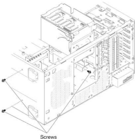
natural_image
Technical line drawing of a computer tower with visible internal components and screw connections (no text or symbols)Figure94. Harddiskdrivecagescrewremovalfor5Uservermodelwithhot-swappower supplies
- Lifttheharddiskdrivecageoutofthechassis.
Note: You may need to lightly twist and turn the hard disk drive cage in ordertoremove it from the server.

Figure95.Harddiskdrivecageremovalfor5Uservermodelwithhot-swappowersupplies
Replacingtheharddiskdrivecage
Usethisinformationoreplacetheharddiskdrivecage
Toinstalltheharddiskdrivecageon4Uservermodelswithnon-hot-swappower supplies,completethefollowingsteps.Forthe5Uservermodelwithhot-swap powersupplies,pleaseseethenextsub-section.
- Readthesafetyinformationin"Safety"onpageviiand"Installation guidelines"onpage35.
- Presstheharddiskdrivecageinuntilthereleaselatchesclickintoplace.

natural_image
Technical line drawing of a computer tower case with internal components and an arrow indicating a specific part (no text or symbols present)Figure96. Harddiskdrivecageinstallationfor4Uservermodelwithnon-hot-swappower supplies
Note: Makesurethebackplateisalreadyinstalledonthediskdrivecage(see "Replacingthesimple-swapbackplate" onpage234).
- Installtheairbaffle(see"Replacingtheairbaffle"onpage185).
- Installthesidecover(see"Replacingthesidecover"onpage182).
- Standtheserverbackupinitsverticalposition.
- Installthebezel(see"Replacingthebezel"onpage188).
- Reconnecttheexternalcablesandpowercords;then,turnontheattached devicesandturnontheserver.
Toinstalltheharddiskdrivecageon5Uservermodelswithhot-swappower supplies,completethefollowingsteps.For4Uservermodelswithnon-hot-swap powersupplies,pleaseseetheabovesub-section.
- Readthesafetyinformationin"Safety"onpageviiand"Installation guidelines"onpage35.
- Lowertheharddiskdrivecageintothechassis.

Figure97.Harddiskdrivecageinstallationfor5Uservermodelwithhot-swappowersupplies
- Installthescrewstosecuretheharddiskdrivecageintothechassis.

natural_image
Isometric technical diagram of a computer tower with labeled screw assembly (no text or symbols beyond label)Figure98. Harddiskdrivecagescrewinstallationfor5Uservermodelwithhot-swappower supplies
-
Connectthepower, signalandconfigurationcablestotheharddiskdrive backplane (fordetailsregardingthecabling, see "Replacingthehot-swaphard diskdrivebackplane" onpage243).
-
Pressandholdtheretainingtabonthesideofthecage;then,rotatethedrive cageintothechassisuntillocksintoplace.
Note: You may need to slightly lift up the cage in order to press and hold the retaining tab.
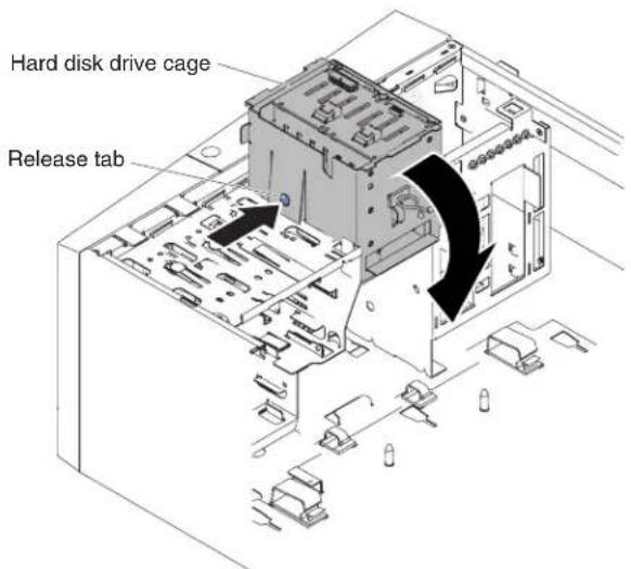
Figure99. Rotatingharddiskdrivecageintochassisfor5Uservermodelwithhot-swap powersupplies
- Installtheharddiskdrivefanductontotheharddiskdrivecage(see "Replacingtheharddiskdrivefanduct" onpage225).
- Standtheserverbackupinitsverticalposition.
- Installthehot-swapharddiskdrivesthatyouremovedfromtheharddisk drivecage(see"Replacingahot-swapharddiskdrive"onpage220).
- Installthelowerbezel(see "Replacingthelowerbezel" onpage190).
- Installandlockthesidecover(see"Replacingthesidecover" on page 182).
- Reconnecttheexternalcablesandpowercords; then, turnontheattached devicesandturnontheserver.
Removingthebatteryholderfrom5Uservermodel
Usethisinformationtoremovethebatteryholderfrom5Uservermodel
Toremovethebatteryholderfromthe5Uservermodelwithhot-swappower supplies,completethefollowingsteps.
- Readthesafetyinformationin"Safety"onpageviiand"Installation guidelines"onpage35.
- Turnoff the server and all attached devices; then, disconnect all power cords and external cables.
- Unlockandremovethesidecover(see"Removingthesidecover" on page 38).
- Carefullyturntheserveronitssidesothatitislyingflat, with theoverfacing up.
Attention: Donotallowtheservertofallover.
- Removethebatteryholderandbracketfromthechassisbyunscrewingthe screw.
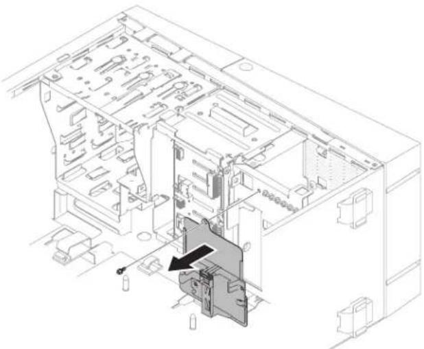
natural_image
Technical line drawing of an internal mechanical assembly with no visible text or symbolsFigure100.Batteryholderandbracketremovalfromchassisfor5Uservermodelwith hot-swappowersupplies
- Removethebatteryholderfromthebracketbyslidingitoutoftheslot.

Figure101.Batteryholderremovalfrombracketfor5Uservermodelwithhot-swappower supplies
- Removethelatchretainerfromthebatteryholder.

Figure102.Latchretainerremovalfrombatteryholderfor5Uservermodelswithhot-swap powersupplies
- If you are instructed to return the battery, follow all packaging instructions, and use anYPackaging materials for shipping that aresupplied to you.
Replacingthebatteryholderon5Uservermodel
Usethisinformationtoreplacethebatteryholderonthe5Uservermodel
Attention: To ensure proper cooling and airflow, donotoperatetheserver for more than 30 minutes with the sidecover removed.
Toinstallthebatteryholderonthe5Uservermodelwithhot-swappower supplies,completethefollowingsteps.
- Readthesafetyinformationin"Safety"onpageviiand"Installation guidelines"onpage35.
- Attachthelatchretainerontothebatteryholder.

Figure103.Latchretainerattachmentontobatteryholderfor5Uservermodelswithhot-swap powersupplies
- Insertthebatteryholderintothebracket.

Figure104. Installing batteryholder intobracket for 5User model with hot-swappower supplies
- Tightenthescrewtosecurethebatteryholderandbrackettothechassis.

Figure105. Installing batteryholder and bracket into chassis for 5 User model with hot-swappowersupplies
-
Standtheserverbackupinitsverticalposition.
-
Installandlockthesidecover(see"Replacingthesidecover"onpage182).
-
Reconnecttheexternalcablesandpowercords;then,turnontheattached devicesandturnontheserver.
RemovingandreplacingTier1CRUs
ThissectionprovidesinformationforremovingandreplacingTier1CRUsinthe server.
ReplacementofTier1CRUsisyourresponsibility.IfIBMinstallsaTier1CRUat yourrequest,youwillbechargedfortheinstallation.
The illustrations in this document might differs slightly from your hardware.
Removing and installing internal drives
Usethisinformationtoremoveandinstallinternaldrives.
The following figures show the locations of the four 3.5" simple-swapharddisk drivebays in the 4User model with non-hot-swappowers supplies.
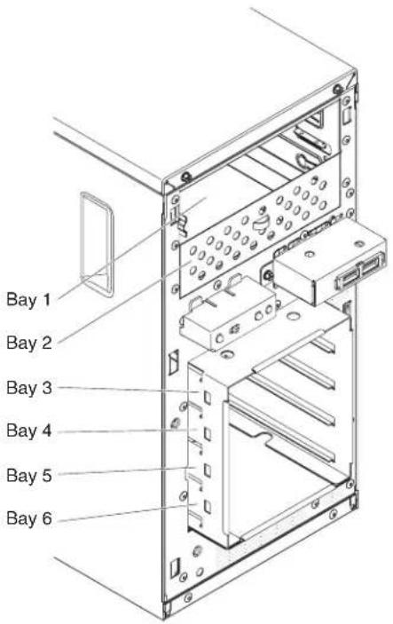
Figure106.Locationofthefour3.5"simple-swapharddiskdrivebaysinthe4Userver modelwithnon-hot-swappowersupplies
The following figures show the location of the eight 2.5" hot-swaphard disk drive bays in the 5 User model with hot-swappowers supplies.

Figure107.Locationoftheeight2.5"hot-swapharddiskdrivebaysinthe5Uservermodel withhot-swappowersupplies
The following figures show the location of the four 3.5" hot-swaphar disk drive bays in the 5 User model with hot-swappowers supplies.

Figure108.Locationofthefour3.5"hot-swapharddiskdrivebaysinthe5Uservermodel withhot-swappowersupplies
The following notes describe the types of drivesthat the servers supports and other information that you must consider when installing a drive:
- Makesurethatyouhaveallthecablesandotherequipmentthatisspecifiedin thedocumentationthatcomeswiththedrive.
- Checktheinstructionsthatcomewiththedrivetoseewhetheryouhavetoset anyswitchesorjumpersonthedrive.IfyouareinstallingaSATAdevice,be suretosettheSATAIDforthatdevice.
- Optional external taped drives, DVD-ROM drive are examples of removable-mediated drives. You can install removable-mediated drives only in bays1 and 2.
•Theelectromagneticinterference(EMI)integrity and cooling of the server are protected by having all bays and PCIslots covered or occupied. When you install a driveor PCI adapter, save the EMC shield and filler panel from the bay or the PCI adapters slot cover in the event that you later removethed driveor adapter.
•Foracompletelistofsupportedoptionsfortheserver,seehttp://www.ibm.com/systems/info/x86servers/serverproven/compat/us
RemovingaDVDdrive:
UsethisinformationtoremoveaDVDdrive.
ToremoveaDVDdrivein4Uservermodelswithnon-hot-swappowersupplies, completethefollowingsteps.Forthe5Uservermodelwithhot-swappower supplies,pleaseseethenextsub-section.
- Readthesafetyinformationin"Safety"onpageviand"Installation guidelines"onpage35.
- Turnoff the server and all attached devices; then, disconnect all power cords and external cables.
- Removethebezel(see"Removingthebezel"onpage40).
- Carefullyturntheserveronitssidesothatitislyingflat, with the cover facing up.
Attention: Donotallowtheservertofallover.
-
Removethesidecover(see"Removingthesidecover"onpage38).
-
Disconnect the power cable and then the signal cables from the drivethatist to be removed.
-
Standtheserverbackupinitsverticalposition.
-
Pressandholdthebluereleasebuttononthesideofthebaytoreleasethe drive;then,pullthedriveoutofthefrontoftheserver.
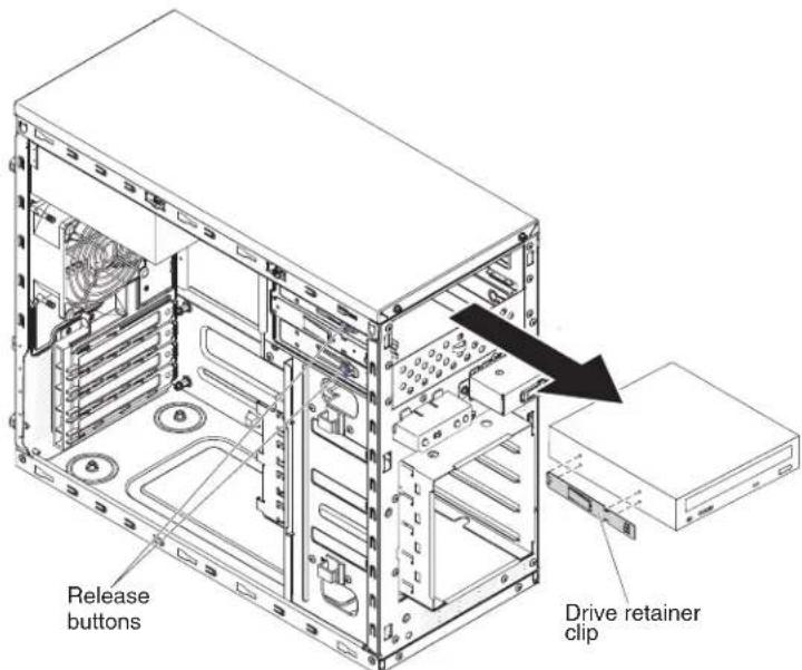
Figure109.DVDdriveremovalfor4Uservermodelwithnon-hot-swappowersupplies
-
Removethedriveretainerclipfromthesideofthedrive.Savethecliptouse whenyouinstallthereplacementdrive.
-
If you are instructed to return the drive, follow wall packaging instructions, and use anYPackaging materials for shipping that aresupplied to you.
Important: To helpensuresystemreliability and electromagnetic compatibility (EMC), makesurethatafillerpanel(partnumberis00KC799) is installed in the drivebay when not taped driveor CD/DVD drive is installed.
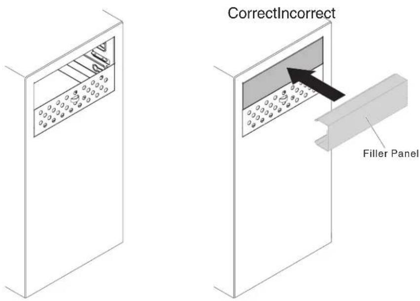
ToremoveaDVDdriveinthe5Uservermodelwithhot-swappowersupplies, completethefollowingsteps.For4Uservermodelswithnon-hot-swappower supplies,pleaseseetheabovesub-section.
-
Readthesafetyinformationin"Safety"onpageviiand"Installation guidelines"onpage35.
-
Turnoff the server and all attached devices; then, disconnect all power cords and external cables.
-
Unlockandremovethesidecover(see"Removingthesidecover"onpage38).
-
Removethelowerbezel(see"Removingthelowerbezel" on page 42).
-
Removetheupperbezel(see"Removingtheupperbezel"onpage43).
-
Disconnect the power and signal cables from the drivethatistoberemoved.
-
Pressandholdtheblue-coloredreleasebuttononthesideofthebaytorelease thedrive;then,pullthedriveoutofthefrontoftheserver.

Figure110.DVDdriveremovalfor5Uservermodelwithhot-swappowersupplies
- Removethedriveretainerclipfromthesideofthedrive.Savethecliptouse whenyouinstallthereplacementdrive.
- If you are instructed to return the drive, follow all packaging instructions, and use anYPackaging materials for shipping that aresupplied to you.
Important: To helpensuresystemreliability and electromagnetic compatibility (EMC), makesurethatafillerpanel(partnumberis00KC799) is installed in the drivebay when not taped driveor CD/DVD drive is installed.

natural_image
Isometric line drawing of a cabinet or enclosure with internal compartments and a door (no text or symbols)
ReplacingtheDVDdrive:
UsethisinformationoreplacetheDVDdrive
If you are replacing a drive, makes sure that:
- Youhaveallthecablesandotherequipmentthatarespecifiedinthe documentationthatcomeswiththenewdrive.
- Youhavecheckedtheinstructionsthatcomewiththenewdrivetodetermine whetheryoumustsetanyswitchesorjumpersinthedrive.
- Youhaveremovedtheblueopticaldriverailsfromthesideoftheolddriveand havethemavailableforinstallationonthenewdrive.
Note: If you are installing a drivethat contains alaser, observ the following safety precautions.
Statement3

CAUTION:
When laser products(suchasCD-ROMs, DVD drives, fiberoptic devices, or transmitters) are installed, not the following:
- Donotremovethecovers.Removingthecoversofthelaserproductcould resultinexposuretohazardouslaserradiation.Therearenoserviceableparts insidethedevice.
- Useofcontrolsoradjustmentsorperformanceofproceduresotherthanthose specifiedhereinmightresultinhazardousradiationexposure.

DANGER
SomelaserproductscontainanembeddedClass3AorClass3Blaserdiode.
Notethefollowing.Laserradiationwhenopen.Donotstareintothebeam, donotviewdirectlywithopticalinstruments,andavodidirectexposureto thebeam.

Class 1 Laser Product
Laser Klasse 1
Laser Klass 1
Luokan 1 Laserlaite
ToinstallaDVDdriveon4Uservermodelswithnon-hot-swappowersupplies, completethefollowingsteps.Forthe5Uservermodelwithhot-swappower supplies,pleaseseethenextsub-section.
- Readthesafetyinformationin"Safety"onpageviiand"Installation guidelines"onpage35.
- Follow the instruction that comewith the drivetosetjumpersorswitches, if there are any.
Note: You might find it asierto install thenew drive from the front and then attach the cables.
-
Touchthestatic-protectivepackagethatcontainsthenewDVDdrivetoany unpaintedmetalsurfaceontheserver;then,removetheDVDdrivefromthe packageandplaceitonastatic-protectivesurface.
-
Standtheserverbackupinitsverticalposition.
-
Removethedriveretainerclipfromthesideofthedrivecageofbay1orbay 2.Slidethedriveretainercliptothefronttoremoveitfromthedrivecage; then, snapthedriveretainerclipintothescrewholesonthesideofthedrive.
-
Pushthedriveintothebay.
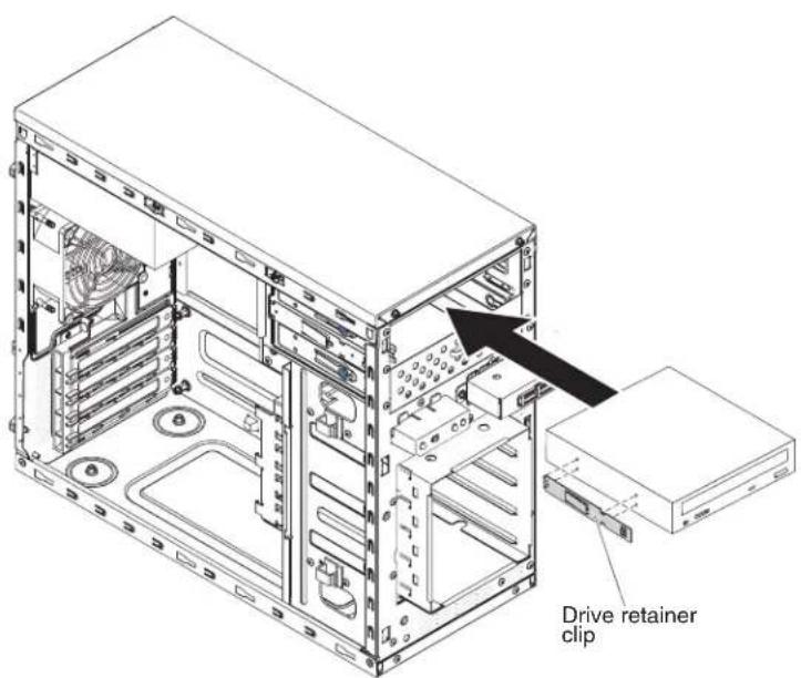
Figure 111. DVD drive installation for 4 User models with non-hot-swappowers supplies
- Carefullyturntheserveronitssidesothatitislyingflat.
Attention: Donotallowtheservertofallover.
- Connectthepower(powerconnectorP9)andsignalcablestothedrive.
Note: Routethesignalcablesothatitdoesnotblocktheairflowtotherearof thedrivesoroverthemicroprocessoranddualinlinememorymodules (DIMMs).
-
If you have another driveto install or remove, do so now.
-
Installthesidecover(see"Replacingthesidecover"onpage182).
-
Installthebezel(see"Replacingthebezel"onpage188).
Note:Removethefillerblockingtheinstalleddriveifany.
- Reconnecttheexternalcablesandpowercords;then,turnontheattached devicesandturnontheserver.
ToinstallaDVDdriveonthe5Usermodelwithhot-swappowersupplies, completethefollowingsteps.For4Uservermodelswithnon-hot-swappower supplies,pleaseseetheabovesub-section.
-
Readthesafetyinformationin"Safety"onpageviiand"Installation guidelines"onpage35.
-
Follow the instruction that comewith the drivetosetjumpersorswitches, if there are any.
Note: You might find it asiertoinstall thenewdrive from the front and then attach the cables.
-
Touchthestatic-protectivepackagethatcontainsthenewDVDdrivetoany unpaintedmetalsurfaceontheserver;then,removetheDVDdrivefromthe packageandplaceitonastatic-protectivesurface.
-
Attachthedriveretainerclipthatyouremovedfromthepreviousdrivetothe sideofthenewdrive.
-
Pushthedriveintothebay.

Figure112.DVDdriveinstallationfor5Uservermodelwithhot-swappowersupplies
- Connectthepowerandsignalcablestothedrive.
Note: Routethesignalcablesothatitdoesnotblocktheairflowtotherearof thedrivesoroverthemicroprocessoranddualinlinememorymodules (DIMMs).
-
Installtheupperbezel(see"Replacingtheupperbezel"onpage192).
-
Installthelowerbezel(see"Replacingthelowerbezel"onpage190).
-
Installandlockthesidecover(see"Replacingthesidecover" on page 182).
-
Reconnecttheexternalcablesandpowercords;then,turnontheattached devicesandturnontheserver.
Removingatapedrive:
Usethisinformationtoremoveatapedrive.
Toremoveatapedriveon4Uservermodelswithnon-hot-swappowersupplies, completethefollowingsteps.Forthe5Uservermodelwithhot-swappower supplies,pleaseseethenextsub-section.
- Readthesafetyinformationin"Safety"onpageviand"Installation guidelines"onpage35.
- Turnoff the server and all attached devices; then, disconnect all power cords and external cables.
- Removethebezel(see"Removingthebezel"onpage40).
- Carefullyturntheserveronitssidesothatitislyingflat, with thecover facingup.
Attention: Donotallowtheservertofallover.
-
Removethesidecover(see"Removingthesidecover"onpage38).
-
Disconnect the power cable and then the signal cables from the drivethatist to be removed.
-
Standtheserverbackupinitsverticalposition.
-
Pressandholdthebluereleasebuttononthesideofthebaytoreleasethe drive;then,pullthedriveoutofthefrontoftheserver.
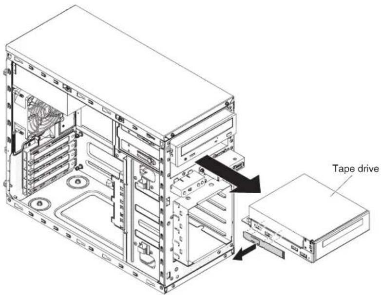
Figure 113. Tapedriveremovalfor4Uservermodelwithnon-hot-swappowersupplies
-
Removethedriveretainerclipfromthesideofthedrive.Savethecliptouse whenyouinstallthereplacementdrive.
-
If you are instructed to return the drive, follow wall packaging instructions, and use an y packaging materials for shipping that a resupplied to you.
Important: To helpensuresystemreliability and electromagnetic compatibility (EMC), makesurethatafillerpanel(partnumberis00KC799) is installed in the drivebaywhennotapedriveorCD/DVDdriveisinstalled.

Toremoveatapedriveonthe5Uservermodelwithhot-swappowersupplies, completethefollowingsteps.For4Uservermodelswithnon-hot-swappower supplies,pleaseseetheabovesub-section.
-
Readthesafetyinformationin"Safety"onpageviiand"Installation guidelines"onpage35.
-
Turnoff the server and all attached devices; then, disconnect all power cords and external cables.
-
Unlockandremovethesidecover(see"Removingthesidecover"onpage38).
-
Removethelowerbezel(see"Removingthelowerbezel" on page 42).
-
Removetheupperbezel(see"Removingtheupperbezel"onpage43).
-
Disconnect the power and signal cables from the drivethatistoberemoved.
-
Pressandholdtheblue-coloredreleasebuttononthesideofthebaytorelease thedrive;then,pullthedriveoutofthefrontoftheserver.
-
Removethedriveretainerclipfromthesideofthedrive.Savethecliptouse whenyouinstallthereplacementdrive.
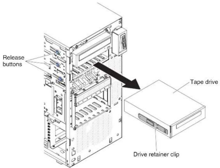
Figure114. Tapedriveremovalfor5Uservermodelwithhot-swappowersupplies
- If you are instructed to return the drive, follow all packaging instructions, and use anYPackaging materials for shipping that a resupplied to you.
Important: To helpensuresystemreliability and electromagnetic compatibility (EMC), makesurethatafillerpanel(partnumberis00KC799) is installed in the drivebay when not taped driveor CD/DVD drive is installed.

natural_image
Isometric line drawing of a cabinet or enclosure with a patterned panel and circular elements (no text or symbols)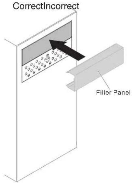
Replacingthetapedrive:
Usethisinformationoreplacethetapedrive
If you are replacing a drive, makes sure that:
- You have all the cables and other equipment that is specified in the documentation that comes with thenew drive.
- Youcheck the instruction that comewith thenew drivetodeterminewhether you must set anyswitchesorjumpersonthedrive.
- Youhaveremovedthedriveretainercliponthesideoftheolddriveandhaveit availableforinstallationonthenewdrive.
Toinstallatapedriveon4Uservermodelswithnon-hot-swappowersupplies, completethefollowingsteps.Forthe5Uservermodelwithhot-swappower supplies,pleaseseethenextsub-section.
- Readthesafetyinformationin"Safety"onpageviiand"Installation guidelines"onpage35.
- Touchthestatic-protectivepackagethatcontainsthedrivetoanyunpainted metalsurfaceontheserver;then,removethedrivefromthepackageand placeitonastatic-protectivesurface.
- Setanyjumpersorswitchesonthedriveaccordingtothedocumentationthat comeswiththedrive.
- Standtheserverbackupinitsverticalposition.
- Removethefillerfromthedrivecage,ifanyispresent.
- Removethedriveretainerclipfromthesideofthedrivecageofbay1orbay 2.Slidethedriveretainercliptothefronttoremoveitfromthedrivecage; then, snapthedriveretainerclipintothescrewholesonthesideofthedrive.
- Pushthedriveintothebay.
Note: Atapedrivecanonlybeinstalledinbay1orbay2

Figure 115. Tapedrive installation for 4 User ver model with non-hot-swappowersupplies
- Carefullyturntheserveronitssidesothatitislyingflat,withthecover facingup.
Attention: Donotallowtheservertofallover. - Connectoneendoftheapplicablesignalcableintotherearofthedriveand makesurethattheotherendofthiscableisconnectedintotheapplicable connectoronthesystemboard.
- Routethesignalcablesothatitdoesnotblocktheairflowtotherearofthe drivesoroverthemicroprocessoranddualinlinememorymodules(DIMMs).
- If you have another drivetoinstallorremove, dosonow.
- Installtheairbaffle(see"Replacingtheairbaffle" onpage185).
- Installthesidecover(see"Replacingthesidecover"onpage182).
- Standtheserverbackupinitsverticalposition.
- Installthebezel(see"Replacingthebezel"onpage188
- Reconnecttheexternalcablesandpowercords;then,turnontheattached devicesandturnontheserver.
Attention: If notaped drive is installed, it is important to install the filler back to the bay.
Toinstallatapedriveonthe5Uservermodelwithhot-swappowersupplies, completethefollowingsteps.For4Uservermodelswithnon-hot-swappower supplies,pleaseseetheabovesub-section.
- Readthesafetyinformationin"Safety"onpageviiand"Installation guidelines"onpage35.
-
Touchthestatic-protectivepackagethatcontainsthedrivetoanyunpainted metalsurfaceontheserver;then,removethedrivefromthepackageand placeitonastatic-protectivesurface.
-
Setanyjumpersorswitchesonthedriveaccordingtothedocumentationthat comeswiththedrive.
- Removethefillerfromthedrivecage,ifanyispresent.
- Attachthedriveretentionclipthatyouremovedfromthepreviousdriveinto thescrewholesonthesideofthenewdrive.
- Pushthedriveintothebay.
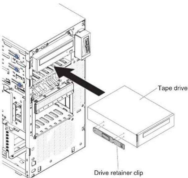
Figure116. Tapedriveinstallationfor5Uservermodelwithhot-swappowersupplies
- Connectoneendoftheapplicablesignalcableintotherearofthedriveand makesurethattheotherendofthiscableisconnectedintotheapplicable connectoronthesystemboard.
- Routethesignalcablesothatitdoesnotblocktheairflowtotherearofthe drivesoroverthemicroprocessoranddualinlinememorymodules(DIMMs).
- Connectthepowercabletotherearofthedrive.Theconnectorsarekeyed andcanbeinsertedonlyoneway.
- Installtheupperbezel(see"Replacingtheupperbezel"onpage192).
- Installthelowerbezel(see "Replacingthelowerbezel" onpage190).
- Installandlockthesidecover(see"Replacingthesidecover"onpage182).
- Reconnecttheexternalcablesandpowercords;then,turnontheattached devicesandturnontheserver.
Removingasimple-swapharddiskdrive:
Thisprocedureappliesonlyto4Uservermodelswithnon-hot-swappower supplies.
Attention: Simple-swapharddiskdrivesarenothot-swappable.Disconnectall powerfromtheserverbeforeyouremoveorinstallasimple-swapharddiskdrive.
Toremoveasimple-swapSATAharddiskdriveon4Uservermodelsthathave non-hot-swappowersupplies,completethefollowingsteps.
- Readthesafetyinformationin"Safety"onpageviiand"Installation guidelines"onpage35.
- Turnoff the server and all attached devices; then, disconnect all power cords and external cables.
- Removethebezel(see"Removingthebezel"onpage40).
- Slidethebluereleaselatchtotherightwithonefinger(toreleasethedrive) whileusinganotherfingertograsptheblackdrivehandleandpullthehard diskdriveoutofthedrivebay.
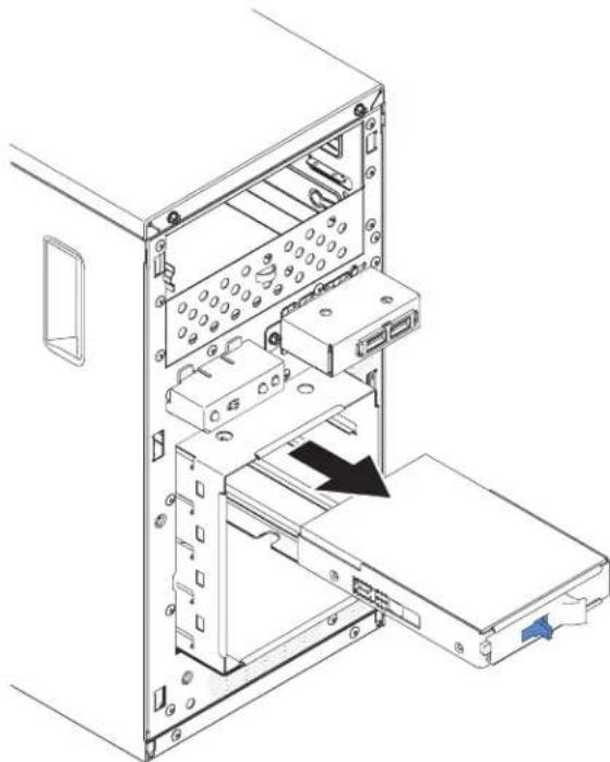
natural_image
Technical line drawing of a computer tower internal structure showing internal components and an external panel (no text or symbols)Figure117.Simple-swapharddiskdriveremovalfor4Uservermodelwithnon-hot-swap powersupplies
- If you are instructed to return the drive assembly, follow all packaging instructions, and use an y packaging materials for shipping that a resupplied to you.
Replacingasimple-swapharddiskdrive:
Thisprocedureappliesonlyto4Uservermodelswithnon-hot-swappower supplies.
The4Usermodelwithnon-hot-swappowersuppliessupportsuptofour 3.5-inchsimple-swapSATAharddiskdrives,whichareaccessiblefromthefrontof theserver.
Note: Only3TBorbelowharddiskdriveoptionsaresupportedbythe4Userver modelwithnon-hot-swappowersupplies.
Youmustdisconnectallpowerfromtheserverbeforeyouremoveorinstall simple-swapdrives.Beforeyouinstallasimple-swapSATAharddiskdrive,read thefollowinginformation:
Installthedrivesstartingfromthetopbaytothebottombay(bay3,4,5,and then 6).ThefollowingtableslisttheIDsoftheharddiskdrives:
Table34.IDsofsimple-swapdrives
| DrivebayHDDID | |
| 3 | 0 |
| 4 | 1 |
| 5 | 2 |
| 6 | 3 |
- Thesimple-swapSATAharddiskdrivesconnecttotheSATA0throughSATA3 connectorsonthesystemboardasfollows:
- Systemboardendcableconnector0connectstotheSATA0connectoronthe systemboard.
- Systemboardendcableconnector1connectstotheSATA1connectoronthe systemboard.
- Systemboardendcableconnector2connectstotheSATA2connectoronthe systemboard.
- Systemboardendcableconnector3connectstotheSATA3connectoronthe systemboard.
-Harddiskdrive0connectstotheSATA0connectoronthesystemboard.
-Harddiskdrive1connectstotheSATA1connectoronthesystemboard.
-Hardiskdrive2connectstotheSATA2connectoronthesystemboard.
-Harddiskdrive3connectstotheSATA3connectoronthesystemboard.
Note: UnderRAIDmode:
- InuEFIsetupmenu:
-Drive0indicatesharddiskdrive0.
- Drive1indicatesharddiskdrive1.
-Drive2indicatesharddiskdrive2.
-Drive3indicatesharddiskdrive3.
- InMegaRAIDStorageManagerutility:
- Slot0indicatesharddiskdrive0.
- Slot1 indicates hard disk drive1.
- Slot2indicatesharddiskdrive2.
- Slot3indicatesharddiskdrive3.
Attention: Simple-swapharddiskdrivesarenothot-swappable.Disconnectall powerfromtheserverbeforeyouremoveorinstallasimple-swapharddiskdrive
Note: If you installed a Serve RAID adapter in the server, connect the other end of the SATAsignal cable to the connector on the Serve RAID adapter.
Toinstallasimple-swapSATAharddiskdriveon4Uservermodelswith non-hot-swappowersupplies,completethefollowingsteps.
- Readthesafetyinformationin"Safety"onpageviiand"Installation guidelines"onpage35.
- Touchthestatic-protectivepackagethatcontainsthedrivetoanyunpainted metalsurfaceontheserver;then,removethedrivefromthepackageandplace itonastatic-protectivesurface.
- Alignthedriveassemblywiththeguiderailsinthebay(theconnectorendof thedrivegoesinfirst).
- Grasptheblackdrivehandleandslidethebluereleaselatchtotheright;then, carefullyslidethedriveassemblyintothedrivebayuntilitstops,andrelease thelatch.

natural_image
Technical line drawing of a computer tower internal structure showing drive bays and an open chassis (no text or labels)Figure 118. Simple-swapharddiskdriveinstallationfor4Uservermodelwithnon-hot-swap powersupplies
- If you have another drivetoinstallorremove, dosonow.
- Installthebezel(see"Replacingthebezel"onpage188).
- Reconnecttheexternalcablesandpowercords;then,turnontheattached devicesandturnontheserver.
Removingahot-swapharddiskdrive:
Thisprocedureappliesonlytothe5Uservermodelwithhot-swappowersupplies.
Attention: Tomaintainpropersystemcooling, donotoperatetheserverformore than 10 minutes without at least one hard disk drive installed in the drive bay.
Toremoveahot-swapharddiskdriveonthe5Uservermodelwithhot-swap powersupplies,completethefollowingsteps.
- Readthesafetyinformationin"Safety"onpageviiand"Installation guidelines"onpage35.
Note: You donothavetoturnofftheserververtoremovehot-swapdrivesfrom thehot-swapdrivebays.
-
Removethelowerbezel(see"Removingthelowerbezel"onpage42).
-
Rotatethedrivetrayhandleofthedriveassemblythatistoberemovedtothe openposition.
The following illustrations show stheremovalofa2.5"hotswapharddiskfrom a5Uservermodelwithhot-swappowersupplies.
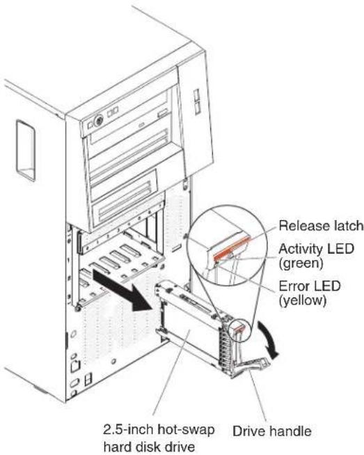
Figure 119.2.5 "hotswapharddiskdriveremovalfor5Uservermodelwithhot-swappower supplies
The following illustrations show stheremovalofa3.5"hotswapharddiskfrom a5Uservermodelwithhot-swappowersupplies.

Figure120.3.5"hotswapharddiskdriveremovalfor5Uservermodelwithhot-swappower supplies
- Graspthehandleofthedriveassemblythatistobereplacedandpullthe assemblyoutofthebay.
- If you are instructed to return the drive assembly, follow all packaging instructions, and use any packaging materials for shipping that a resupplied to you.
Replacingahot-swapharddiskdrive:
Thisprocedureappliesonlytothe5Uservermodelwithhot-swappowersupplies.
If you are replacing a drive, makes sure that:
•Thehot-swapdrivesmustbeeitherallSASharddiskdrivesorallSATAhard diskdrives;thetwotypescannotbecombined.
- Inspectthedrivetrayforsignsofdamage.
• Tomaintainpropersystemcooling, donotoperatetheserverformorethan10 minutes without at least one hard disk drive installed in the drive bay.
- Youdonothavetoturnofftheservertoinstallhot-swapdrivesinthehot-swap drivebays.
Toinstallahot-swapharddiskdriveonthe5Uservermodelthathavehot-swap powersupplies,completethefollowingsteps.
The following illustrations show the installation of a 2.5" hot swaphard disk for 5User vermodel with hot-swappowersupplies.

Figure121.2.5"hotswapharddiskdriveinstallationfor5Uservermodelwithhot-swap powersupplies
The following illustrations show the installation of a 3.5"hotswapharddisk for 5Usermodel with hot-swappowersupplies.

Figure122.3.5"hotswapharddiskdriveinstallationfor5Uservermodelwithhot-swap powersupplies
-
Readthesafetyinformationin"Safety"onpageviand"Installation guidelines"onpage35.
-
Touchthestatic-protectivepackagethatcontainsthedrivetoanyunpainted metalsurfaceontheserver;then,removethedrivefromthepackageandplaceitonastatic-protectivesurface.
- Makesurethatthedrivetrayhandleisintheopenposition.
- Alignthedriveassemblywiththeguiderailsinthebay;then,carefullyslide thedriveassemblyintothedrivebayuntilthedrivestops.
- Rotatethedrivetrayhandletotheclosedposition.
- Checktheharddiskdrivestatusindicatortomakesurethattheharddisk driveisoperatingcorrectly.(Youmighthavetorestarttheserverforthedrive toberecognized.)IftheyellowharddiskdrivestatusLEDforadriveislit continuously,itindicatesthatthedriveisfaultyandmustbereplaced.Ifthe greenharddiskdriveactivityLEDisflashing,thisindicatesthatthedriveis beingaccessed.
Note: If the server is configured for RAID operation using a Serve RAID controller, you might have to configure the disk arrays after you replace hard disk drives. See the Serve RAID documentation for additional information about RAID operation and complete instructions for using Serve RAID Manager.
- Installthelowerbezel(see"Replacingthelowerbezel"onpage190).
Removingtheharddiskdrivefanduct
Thisprocedureappliesonlytothe5Uservermodelwithhot-swappowersupplies.
Toremovetheharddiskdrivefanductonthe5Uservermodelwithhot-swap powersupplies,completethefollowingsteps.
- Turnoff the server and all attached devices; then, disconnect all power cords and external cables.
- Unlockandremovethesidecover(see "Removingthesidecover" on page 38).
- Carefullyturntheserveronitssidesothatitislyingflat,withthesystem boardfacingup.
Attention: Donotallowtheservertofallover.
- Unfastentheretentionclipsthatsecuretheharddiskdrivefanductcable and thendisconnecttheharddiskdrivefanductcablefromthesystemboard. The followingillustrationisfor5Uservermodelswith2.5"hotswapharddisk drivesinstalled.

Figure123.2.5"harddiskdrivefanductcableremovalfor5Uservermodelwithhot-swap powersupplies
The following illustration is for 5User models with 3.5" hotswaphard disk drives installed.

Figure124.3.5"harddiskdrivefanductcableremovalfor5Uservermodelwithhot-swap powersupplies
- Grasptheharddiskdrivefanductbythebluepointandpulluptoliftitout ofthechassis.
The following illustration is for 5User models with 2.5" hotswaphard disk drives installed.

Figure125.2.5"harddiskdrivefanductremovalfor5Uservermodelwithhot-swappower supplies
The following illustration is for 5User vermodel with 3.5" hotswapharddisk drives installed.

Figure126.3.5"harddiskdrivefanductremovalfor5Uservermodelwithhot-swappower supplies
- If you are instructed to return the fan, follow all packaging instructions, and use any packaging materials for shipping that a resupplied to you.
Replacingtheharddiskdrivefanduct
Thisprocedureapppliesonlytothe5Uservermodelwithhot-swappowersupplies.
Attention: To ensure proper cooling and airflow, donotoperatetheserver for more than 30 minutes with these decover removed.
Toinstalltheharddiskdrivefanductonthe5Uservermodelwithhot-swap powersupplies,completethefollowingsteps.
-
Readthesafetyinformationin"Safety"onpageviiand"Installation guidelines"onpage35.
-
Lowertheharddiskdrivefanductintothechassis,makingsurethetwoguide pinsandtwolatchesonthechassisprotrudethroughtherespectiveholeson theharddiskdrivefanduct.
The following illustration is for 5User vermodelswith2.5"hotswapharddisk drives installed.
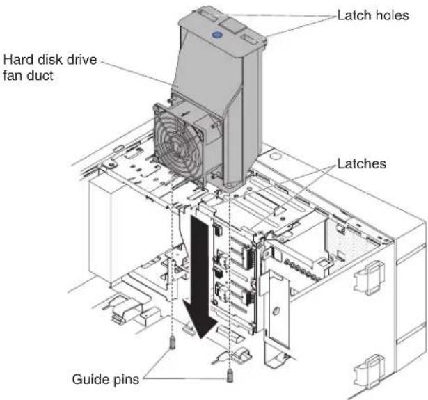
Figure127.2.5"harddiskdrivefanductinstallationfor5Uservermodelwithhot-swappower supplies
The following illustration is for 5User models with 3.5" hotswaphard disk drives installed.

Figure128.3.5"harddiskdrivefanductinstallationfor5Uservermodelwithhot-swappower supplies
- Connecttheharddiskdrivefanductcabletothesystemboard(see "System-boardinternalconnectors" onpage30forthelocationofthefan assemblyconnector).
Attention: Remembertoinserttheharddiskdrivefanductcableintothe relevantretentionclips.
The following illustration is for 5User models with 2.5" hotswapharddisk drives installed.

Figure129.2.5"harddiskdrivefanductcableinstallationfor5Uservermodelwithhot-swap powersupplies
The following illustration is for 5User models with 3.5" hotswapharddisk drives installed.
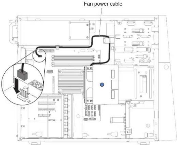
Figure130.3.5"harddiskdrivefanductcableinstallationfor5Uservermodelwithhot-swap powersupplies
- Standtheserverbackupinitsverticalposition.
- Installandlockthesidecover(see"Replacingthesidecover"onpage182).
- Reconnecttheexternalcablesandpowercords;then,turnontheattached devicesandturnontheserver.
RemovingtheUSBembeddedhypervisorflashdevice
Use this information to remove the USB embedded hypervisor flash device.
ToremovetheUSBhypervisorkeyon4Uservermodelswithnon-hot-swappower supplies,completethefollowingsteps.Forthe5Uservermodelwithhot-swap powersupplies,pleaseseethenextsub-section.
- Readthesafetyinformationin"Safety"onpageviand"Installation guidelines"onpage35.
- Turnoff the server and all peripheral devices; then, disconnect the power cords and all external cables.
- Carefullyturntheserveronitssidesothatitislyingflat,withthecoverfacing up.
Attention: Donotallowtheservertofallover.
- Removethesidecover(see"Removingthesidecover"onpage38).
- Removetheairbaffle(see"Removingtheairbaffle"onpage39).
- LocatetheUSBembeddedhypervisorflashdeviceconnectoronthesystem board.

Figure131.USBhypervisorflashdeviceconnectorlocationonsystemboardfor4Userver modelwithnon-hot-swappowersupplies
- Slidethelockbarontheflashdeviceconnectortotheunlockedpositionand pulltheUSBflashdeviceoutoftheconnector.

Figure132. USBhypervisorflashdeviceremovalfromsystemboardfor4Uservermodel withnon-hot-swappowersupplies
- If you are instructed to return the hypervisormemory key, follow all packaging instructions, and use an app packaging materials for shipping that a resupplied to you.
Note: You must configure the server not to look for the hypervisor USB drive. See "Configuring the server" on page 94 for information about disabling hypervisors support.
Toremovethesystemboardonthe5Uservermodelwithhot-swappower supplies,completethefollowingsteps.For4Uservermodelswithnon-hot-swap powersupplies,pleaseseetheabovesub-section.
- Readthesafetyinformationin"Safety"onpageviand"Installation guidelines"onpage35.
- Turnoff the server and all attached devices; then, disconnect all power cords and external cables.
- Unlockandremovethesidecover(see"Removingthesidecover" on page 38).
- Carefully turn the server on its sides that it is lying flat, with the system board facing up.
Attention: Donotallowtheservertofallover. - Rotatetherearadapter-retentionbrackettotheopen(unlocked)position.
- LocatetheUSBembeddedhypervisorflashdeviceconnectoronthesystem board.

Figure133.USBhypervisorflashdeviceconnectorlocationonsystemboardfor5Userver modelwithhot-swappowersupplies
- Slidethelockbarontheflashdeviceconnectortotheunlockedpositionand pulltheUSBflashdeviceoutoftheconnector.

Figure 134. USBhypervisorflashdeviceremovalfromsystemboardfor5Uservermodel withhot-swappowersupplies
- If you are instructed to return the hypervisormemory key, follow all packaging instructions, and use an app packaging materials for shipping that a resupplied to you.
Note: You must configure the server not to look for the hypervisor USB drive. See "Configuring the server" on page 94 for information about disabling hypervisors support.
ReplacingtheUSBembeddedhypervisorflashdevice
UsethisinformationtoreplaceaUSBembeddedhypervisorflashdevice.
ToinstallaUSBembeddedhypervisorflashdeviceon4Uservermodelswith non-hot-swappowersupplies,completethefollowingsteps.Forthe5Userver modelwithhot-swappowersupplies,pleasesecthenextsub-section.
-
Readthesafetyinformationin"Safety"onpageviiand"Installation guidelines"onpage35.
-
LocatetheUSBembeddedhypervisorflashdeviceconnectoronthesystem board.

Figure135.USBhypervisorflashdeviceconnectorlocationonsystemboardfor4Userver modelwithnon-hot-swappowersupplies
- AligntheUSBflashdevicewiththeconnectoronthesystemboardandpushit intotheconnectoruntilitisfirmlyseated.
- Slidethelockbartowardtheriser-cardassemblytothelockedpositionuntil isseatedfirmly.

Figure136.USBhypervisorflashdeviceinstallationfor4Uservermodelwithnon-hot-swap powersupplies
- Installtheairbaffle(see "Replacingtheairbaffle" onpage185).
- Installthesidecover(see "Replacingthesidecover" on page 182).
- Standtheserverbackupinitsverticalposition.
- Reconnecttheexternalcablesandpowercords;then,turnontheattached devicesandturnontheserver.
Toinstallthesystemboardonthe5Uservermodelwithhot-swappowersupplies, completethefollowingsteps.For4Uservermodelswithnon-hot-swappower supplies,pleaseseetheabovesub-section.
- Readthesafetyinformationin"Safety"onpageviand"Installation guidelines"onpage35.
- LocatetheUSBembeddedhypervisorflashdeviceconnectoronthesystem board.

Figure137. USBhypervisorflashdeviceconnectorlocationonsystemboardfor5Userver modelwithhot-swappowersupplies
- AligntheUSBflashdevicewiththeconnectoronthesystemboardandpushit intotheconnectoruntilitisfirmlyseated.
- Slidethelockbartowardtheriser-cardassemblytothelockedpositionuntil isseatedfirmly.
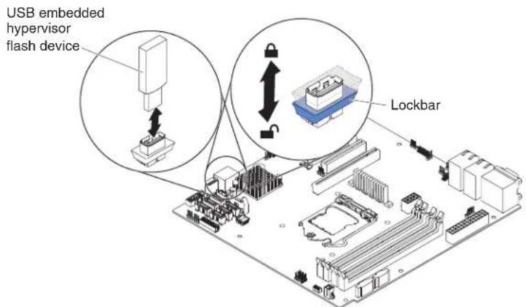
Figure138.USBhypervisorflashdeviceinstallationfor5Usermodelwithhot-swappower supplies
- Rotatetherearadapter-retentionbrackettotheclosed(locked)position.
- Standtheserverbackupinitsverticalposition.
-
Installandlockthesidecover(see"Replacingthesidecover"onpage182).
-
Reconnecttheexternalcablesandpowercords;then,turnontheattached devicesandturnontheserver.
Removingthesimple-swapbackplate
Thisprocedureappliesonlyto4Uservermodelswithnon-hot-swappower supplies.
Toremovethesimple-swapbackplateon4Uservermodelswithnon-hot-swap powersupplies,completethefollowingsteps.
Note: You need as crew driver in order to complete the steps.
- Readthesafetyinformationin"Safety"onpageviand"Installation guidelines"onpage35.
- Turnoff the server and all attached devices; then, disconnect all power cords and external cables.
- Removethebezel(see"Removingthebezel"onpage40).
- Carefullyturntheserveronitssidesothatitislyingflat,withthecover facingup.
Attention: Donotallowtheserverterofallover.
- Removethesidecover(see"Removingthesidecover" on page 38).
- Removetheairbaffle(see"Removingtheairbaffle" onpage39).
- Removethesimple-swapharddiskdrivesthatareinstalledintheharddisk drivecage(see"Removingasimple-swapharddiskdrive" onpage216).
- Toremovethesimple-swapbackplate, slideitoutwardsandthenrotateitout oftheharddiskdrivecage.

Figure139. Simple-swapbackplateremovalfor4Uservermodelwithnon-hot-swappower supplies
- Disconnect the powercable from the simple swapback plate and then the signalcable from the system board.
Note: Thesignalcablesonthesimple-swapbackplatecannotberemoved.
- If you are instructed to return the simple swap back plate, follow all packaging instructions, and use an y packaging materials for shipping that a resupplied to you.
Replacingthesimple-swapbackplate
Thisprocedureapplicsonlyto4Uservermodelswithnon-hot-swappower supplies.
Toinstallthesimple-swapbackplateon4Uservermodelswithnon-hot-swap powersupplies,completethefollowingsteps.
-
Readthesafetyinformationin"Safety"onpageviiand"Installation guidelines"onpage35.
-
Pressandholdtheharddiskdrivecagereleaselatchestopullthedrivecage out.

Figure140. Harddiskdrivecageremovalfor4Uservermodelwithnon-hot-swappower supplies
- Alignthebottomedgeofthesimple-swapbackplatebetweenthetabsandthe bottomedgeoftheharddiskdrivecage(areacoloredingreen),thenrotate thebackplatetowardtheharddiskdrivecageandslideitinwards.
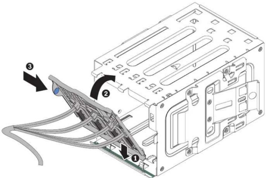
Figure141. Simple-swapbackplateinstallationinharddiskdrivecagefor4Uservermodel withnon-hot-swappowersupplies
- Slidetheharddiskdrivecageintotheopeninginthefrontofthechassistill halfin.

natural_image
Technical line drawing of a computer tower internal structure showing internal components and mounting holes (no text or labels)Figure142. Slidingharddiskdrivecagehalfinintochassisfor4Uservermodelwith non-hot-swappowersupplies
-
Connecttheharddiskdrivepowercablestothebackplate(connectorP3tobay3,connectorP4tobay4,connectorP5tobay5,andconnectorP6tobay6,).
-
ConnecttheharddiskdrivesignalcablestotheSATAconnectorsonthe systemboardortheconnectorontheadapter(ifoneisinstalled).
Note: In the LSIRAIDutility, SATA1 represents sharddisk drive in drive bay two and SATA2 represents sharddisk drive in drive bay one (see "Replacing a simple-swapharddisk drive" on page 217).
The following illustrations show the SATA connector on the system board:
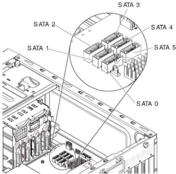
Figure143.SATAconnectorlocationonsystemboardfor4Uservermodelwithnon-hot-swap powersupplies
- Pushharddiskdrivecageinuntilthereleaselatchesclickintoplace.

natural_image
Technical line drawing of a computer tower case with internal components and an arrow indicating a specific space (no text or symbols present)Figure144.Pushingharddiskdrivecageintochassisfor4Uservermodelwithnon-hot-swap powersupplies
- Installthesimple-swapharddiskdrivesthatyouremovedfromtheharddisk drivecage(see"Replacingasimple-swapharddiskdrive"onpage217).
- Installtheairbaffle(see"Replacingtheairbaffle"onpage185).
- Installthesidecover(see"Replacingthesidecover"onpage182).
- Stand the server backup in its vertical position.
- Installbezel(see"Replacingthebezel"onpage188).
- Reconnecttheexternalcablesandpowercords;then,turnontheattached devicesandturnontheserver.
ReplacingsoftwareRAIDsimple-swapharddiskdrivebackplate withhardwareRAIDsimple-swapharddiskdrivebackplate
Thisprocedureappliesonlyto4Uservermodelswithnon-hot-swappower supplies.
ToreplacethesoftwareRAIDsimple-swapharddiskdrivebackplate with hardwareRAIDsimple-swapharddiskdrivebackplate, completethefollowing steps:
- Readthesafetyinformationin"Safety"onpageviiand"Installation guidelines"onpage35.
- Turnoff the server and all attached devices; then, disconnect all power cords and external cables.
- Removethesimple-swapbackplate(see"Removingthesimple-swap backplate"onpage233).
- Alignthebottomedgeofthesimple-swapbackplatebetweenthetabsand the bottomedgeoftheharddiskdrivecage(areacoloredingrey),thenrotatethe backplatetowardtheharddiskdrivecageandslideitinwards.

Figure 145. Installingsimple-swapbackplateinharddiskdrivecagefor4Uservermodelwith non-hot-swappowersupplies
- Slidetheharddiskdrivecageintotheopeninginthefrontofthechassistill halfin.
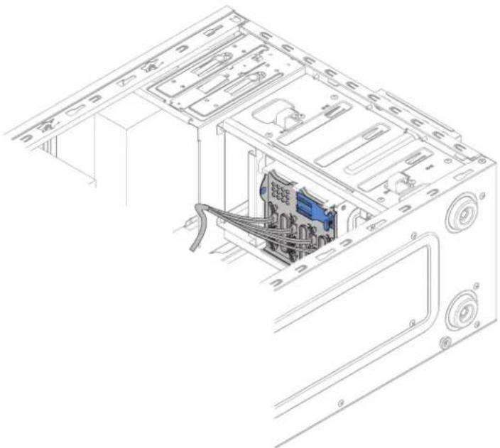
natural_image
Technical line drawing of a computer tower internal structure showing internal components and mounting holes (no text or labels)Figure 146. Slidingharddiskdrivecagehalfinintochassisfor4Uservermodelwith non-hot-swappowersupplies
-
Connecttheharddiskdrivepowercablestothebackplate(connectorP3tobay3,connectorP4tobay4,connectorP5tobay5,andconnectorP6tobay6).
-
ConnecttheharddiskdrivesignalcabletotheSASconnectorontheadapter.
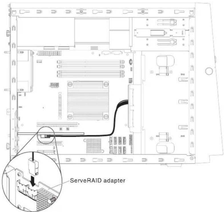
Figure147. HarddiskdrivesignalcableconnectiontoSASconnectorodapterfor4U servermodelwithnon-hot-swappowersupplies
- Securethecableswiththeretentionclips.
- Pushharddiskdrivecageinuntilthereleaselatchesclickintoplace.
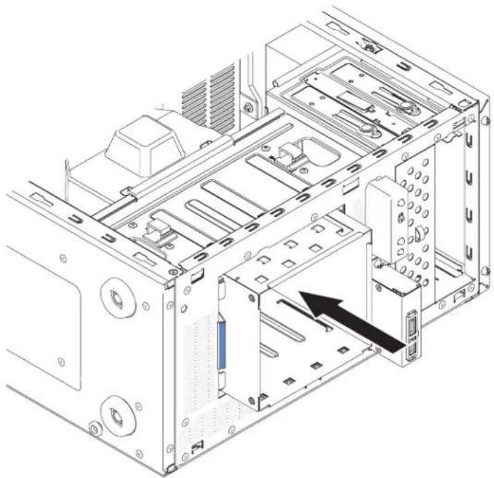
natural_image
Technical line drawing of a computer tower case with internal components and an arrow indicating a specific part (no text or symbols present)Figure148.Pushingharddiskdrivecageintochassisfor4Uservermodelwithnon-hot-swap powersupplies
- Installthesimple-swapharddiskdrivesthatyouremovedfromtheharddisk drivecage(see"Replacingasimple-swapharddiskdrive"onpage217).
- Installtheairbaffle(see "Replacingtheairbaffle" on page 185).
- Installthesidecover(see"Replacingthesidecover"onpage182).
- Standtheserverbackupinitsverticalposition.
- Installbezel(see "Replacingthebezel" onpage188).
- Reconnecttheexternalcablesandpowercords;then,turnontheattached devicesandturnontheserver.
Removingthehot-swapharddiskdrivebackplane
Thisprocedureapplicsonlytothe5Uservermodelwithhot-swappowersupplies.
Toremovethehot-swapbackplaneonthe5Uservermodelwithhot-swappower supplies,completethefollowingsteps.
- Readthesafetyinformationin"Safety"onpageviiand"Installation guidelines"onpage35.
- Turnoff the server and all attached devices; then, disconnect all power cords and external cables.
- Unlockandremovethesidecover(see"Removingthesidecover" on page 38).
- Removethelowerbezel(see"Removingthelowerbezel" onpage42).
- Removethehot-swapSAS/SATAharddiskdrivesinstalledintheharddisk drivecage(see "Removingahot-swapharddiskdrive" onpage219).
- Carefullyturntheserveronitssidesothatitislyingflat,withthesystem boardfacingup.
Attention: Donotallowtheservertofallover.
-
Removetheharddiskdrivefanduct(see"Removingtheharddiskdrivefanduct"onpage222).Doingsorequiresremovingthecablesfromthecable clips.
-
Pressandholdtheharddiskdrivecagereleasetab;then,rotatetheharddisk drivecageoutofthechassisuntiltheretainingtabontopofthecagelocks intoplace.

Figure149. Rotatingharddiskdrivecageoutofchassisfor5Uservermodelwithhot-swap powersupplies
- Disconnect the power, signal and configuration cables from the hard disk drive back plane.
The following illustration is for 5User models with 2.5" hotswaphard disk drives installed.
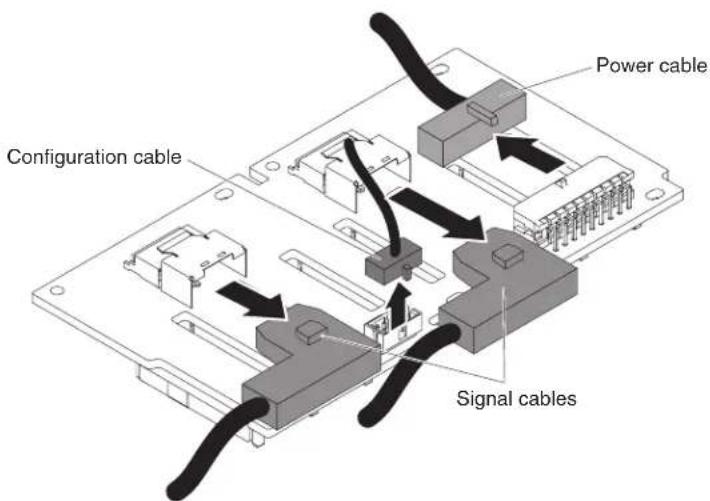
Figure150.2.5"hotswapharddiskdrivebackplanecablingremovalfor5Uservermodel withhot-swappowersupplies
The following illustration is for 5User vermodel with 3.5" hotswaphard disk drives installed.

Figure151.3.5"hotswapharddiskdrivebackplanecablingremovalfor5Uservermodel withhot-swappowersupplies
- RemovethescrewsthatsecuretheSAS/SATAharddiskdrivebackplaneto thedrivecage.
Note:
- A total offours crews need to be removed for back planest that support 2.5" hotswaphard disk drives.
- Atotaloftwoscrewsneedtoberemovedforbackplanesthatsupport3.5" hotswapharddiskdrives.
The following illustration is for 5User vermodel with 2.5" hotswaphard disk drives installed.
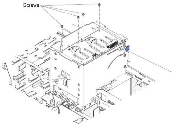
Figure 152.2.5"hotswapharddiskdrivebackplanescrewremovalfor5Uservermodelwith hot-swappowersupplies
The following illustration is for 5User models with 3.5" hotswaphard disk drives installed.

Figure153.3.5"hotswapharddiskdrivebackplanescrewremovalfor5Uservermodelwith hot-swappowersupplies
- Liftthehot-swapbackplaneoutofthelowerliponthedrivecageandsetit aside.
- If you are instructed to return the SAS/SATAhard disk drive backplane, follow all packaging instructions, and use an y packaging materials for shipping that a resupplied to you.
Replacingthehot-swapharddiskdrivebackplane
Thisprocedureappliesonlytothe5Uservermodelwithhot-swappowersupplies.
Toinstalltheharddiskdrivebackplaneonthe5Uservermodelwithhot-swap powersupplies,completethefollowingsteps.
-
Readthesafetyinformationin"Safety"onpageviiand"Installation guidelines"onpage35.
-
Placethebottomedgeofthehot-swapharddiskdrivebackplaneinthelower lipofthedrivecage.
-
Connectthepower, signalandconfigurationcablestotheharddiskdrive backplane.
Note: MakesurethatPort1onthehardwareServeRAIDisconnectedtoPort1onthebackplane. Likewise, Port0onthehardwareServeRAIDshouldbe connectedtoPort0onthebackplane.
The following illustration is for 5User vermodelswith2.5"hotswaphard disk drives installed.

Figure154.2.5"hotswapharddiskdrivebackplanecablinginstallationfor5Uservermodel withhot-swappowersupplies
The following illustration is for 5User models with 3.5"hotswaphard disk drives installed.

Figure155.3.5"hotswapharddiskdrivebackplanecablinginstallationfor5Uservermodel withhot-swappowersupplies
- Installthescrewsthatsecurethehot-swapharddiskdrivebackplanetothe drivecage.
Note:
- A total offours crews needtobe installed for backplanesthatsupport2.5" hot-swapharddiskdrives.
- Atotaloftwoscrewsneedtobeinstalledforbackplanesthatsupport3.5" hot-swapharddiskdrives.
The following illustration is for 5User vermodelswith2.5"hotswaphard disk drives installed.

Figure156.2.5"hotswapharddiskdrivebackplanescrewinstallationfor5Uservermodel withhot-swappowersupplies
The following illustration is for 5User vermodel with 3.5" hotswaphard disk drives installed.
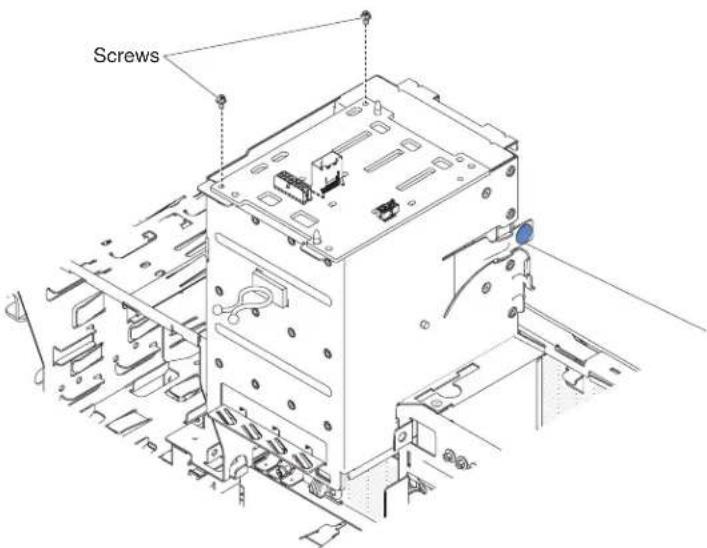
Figure157.3.5"hotswapharddiskdrivebackplanescrewinstallationfor5Uservermodel withhot-swappowersupplies
- Pressandholdtheretainingtabonthesideofthecage;then,rotatethedrive cageintothechassisuntillocksintoplace.
Note: You may need to slightly lift up the cage in order to press and hold the retaining tab.
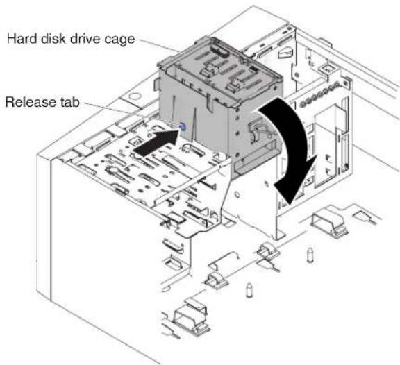
Figure158. Rotatingharddiskdrivecageintochassisfor5Uservermodelwithhot-swap powersupplies
- Installtheharddiskdrivefanductontotheharddiskdrivecage(see "Replacingtheharddiskdrivefanduct" onpage225).
- Standtheserverbackupinitsverticalposition.
- Installthehot-swapharddiskdrivesthatyouremovedfromtheharddisk drivecage(see"Replacingahot-swapharddiskdrive"onpage220).
- Installthelowerbezel(see"Replacingthelowerbezel"onpage190).
- Installandlockthesidecover(see"Replacingthesidecover"onpage182).
- Reconnecttheexternalcablesandpowercords; then, turnontheattached devicesandturnontheserver.
Removing the operator information panel assembly
Usethisinformationtoremovetheoperatorinformationpanelassembly
Toremovetheoperatorinformationpanelassemblyon4Uservermodelswith non-hot-swappowersupplies,completethefollowingsteps.Forthe5Userver modelwithhot-swappowersupplies,pleaseseethenextsub-section.
- Readthesafetyinformationin"Safety"onpageviiand"Installation guidelines"onpage35.
- Turnoff the server and all peripheral devices; then, disconnect the power cords and all external cables.
- Removethebezel(see"Removingthebezel"onpage40).
- Carefullyturntheserveronitssidesothatitislyingflat,withthecover facingup.
Attention: Donotallowtheservertofallover.
- Removethesidecover(see "Removingthesidecover" on page 38).
- Removetheairbaffle(see "Removingtheairbaffle" on page 39).
- Disconnect the operator information panel assembly cable from the system board, and not ether routing of the cable (see "System-board internal connectors" on page 30 for the location of the operator information panel assembly connector).
-
Standtheserverbackupinitsverticalposition.
-
Pressontopoftheoperatorinformationpanelassemblyandrotatethe assemblytowardthebottomoftheserver;then,removetheoperator informationpanelassemblyfromthechassis.

natural_image
Technical line drawing of an internal server rack with a central component (no text or symbols)Figure 159. Operator information panel assembly removal for 4 User vermodel with non-hot-swappowersupplies
Note: Carefully pull the cable out from the opening. Donot allow the LED to disconnect from the operator information panel assembly.
- If you are instructed to return the operator information panel assembly, follow all packaging instructions, and use an typ packaging materials for shipping that aresupplied to you.
Toremovetheoperatorinformationpanelassemblyonthe5Uservermodelwith hot-swappowersupplies,completethefollowingsteps.For4Uservermodelswith non-hot-swappowersupplies,pleaseseetheabovesub-section.
-
Readthesafetyinformationin"Safety"onpageviiand"Installation guidelines"onpage35.
-
Turnoff the server and all attached devices; then, disconnect all power cords and external cables.
-
Unlockandremovethesidecover(see "Removingthesidecover" on page 38).
-
Removethelowerbezel(see"Removingthelowerbezel"onpage42).
-
Removetheupperbezel(see"Removingtheupperbezel"onpage43).
-
Slidethedrivesinbay1andbay2forwardslightly(see"RemovirgaDVD drive"onpage204ard"Removingatapedrive"onpage210formore information).Itisnotnecessarytoremovethesedrives.
-
Carefullyturntheserveronitssidesothatitislyingflat,withthesystem boardfacingup.
Attention: Donotallowtheserverterofallover.
-
Removethehot-swappowersuppliesandthehot-swappower-supplycage (see"Removingthehot-swappowersupply"onpage263)and"Removingthe hot-swappowersupplycage"onpage295).
-
Disconnect the operator information panel assembly cable from the system board, and not ether routing of the cable (see "System-board internal connectors" on page 30 for the location of the operator information panel assembly connector).
-
Pressonthereleasetaboftheoperatorinformationpanelassemblyandpull theassemblytowardtherearoftheserver;then,removetheoperator informationpanelassemblyfromthechassis.

Figure160. Operatorinformationpanelassemblyremovalfor5Uservermodelwithhot-swap powersupplies
- If you are instructed to return the operator information panel assembly, follow all packaging instructions, and use an typ packaging materials for shipping that a resupplied toy you.
Replacing the operator information panel assembly
Usethisinformationtoreplacetheoperatorinformationpanelassembly
Toinstalltheoperatorinformationpanelassemblyon4Uservermodelswith non-hot-swappowersupplies,completethefollowingsteps.Forthe5Userver modelwithhot-swappowersupplies,pleaseseethenextsub-section.
-
Readthesafetyinformationin"Safety"onpageviiand"Installation guidelines"onpage35.
-
Reroutetheoperatorinformationpanelassemblycableintotheopening.
Note: Carefully pull the cable out from the opening. Donot allow the LED to disconnect from the operator information panel assembly.
- Insertthebottomtabsoftheoperatorinformationpanelassemblyintothe correspondingholesandrotatetheassemblytowardthechassis.
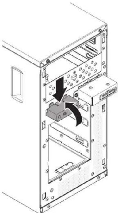
natural_image
Technical diagram of a computer tower internal structure showing internal components and a black arrow indicating a directional flow (no text or labels present)Figure161. Operatorinformationpanelassemblyinstallationfor4Uservermodelwith non-hot-swappowersupplies
- Pushtheoperatorinformationpanelassemblytowardthechassisuntil clicksintoplace.
- Rerouteandconnecttheoperatorinformationpanelassemblycabletothesystemboard(see"System-boardinternalconnectors"onpage30forthelocationoftheoperatorinformationpanelassemblyconnector).
- Installtheairbaffle(see"Replacingtheairbaffle"onpage185).
- Installthesidecover(see"Replacingthesidecover"onpage182).
- Standtheserverbackupinitsverticalposition.
- Installbezel(see"Replacingthebezel"onpage188).
- Reconnecttheexternalcablesandpowercords;then,turnontheattached devicesandturnontheserver.
Toinstalltheoperatorinformationpanelassemblyonthe5Uservermodelwith hot-swappowersupplies,completethefollowingsteps.For4Uservermodelswith non-hot-swappowersupplies,pleaseseetheabovesub-section.
- Readthesafetyinformationin"Safety"onpageviiand"Installation guidelines"onpage35.
- Carefullyturntheserveronitssidesothatitislyingflat.
Attention: Donotallowtheservertofallover.
-
Positionthefrontendoftheoperatorinformationpanelassemblyinthe channelabovebay1.
-
Pushtheoperatorinformationpanelassemblytowardthefrontofthechassis untilclicksintoplace.

Figure162. Operatorinformationpanelassemblyinstallationfor5Uservermodelwith hot-swappowersupplies
- Rerouteandconnecttheoperatorinformationpanelassemblycabletothe systemboard(see"System-boardinternalconnectors"onpage30forthe locationoftheoperatorinformationpanelassemblyconnector).
- Install the power-supply cage and the powers supplies (see "Replacing the hot-swappowersupplycage" on page 297 and "Replacing the hot-swap powersupply" on page 264).
- Pushthedrivesinbay1andbay2intothedrivebays(see "Replacing the DVDdrive" onpage207 and "Replacingthetapedrive" onpage213 formore information).
- Standtheserverbackupinitsverticalposition.
- Installtheupperbezel(see"Replacingtheupperbezel"onpage192).
- Installthelowerbezel(see"Replacingthelowerbezel"onpage190).
- Installandlockthesidecover(see "Replacingthesidecover" on page 182).
- Reconnecttheexternalcablesandpowercords;then,turnontheattached devicesandturnontheserver.
RemovingthefrontUSBconnectorassembly
UsethisinformationtoremovethefrontUSBconnectorassembly
ToremovethefrontUSBconnectorassemblyon4Uservermodelswith non-hot-swappowersupplies,completethefollowingsteps.Forthe5Userver modelwithhot-swappowersupplies,pleaseseethenextsub-section.
- Readthesafetyinformationin"Safety"onpageviiand"Installation guidelines"onpage35.
- Turnoff the server and all peripheral devices; then, disconnect the power cords and all external cables.
- Removethebezel(see"Removingthebezel"onpage40).
- Carefullyturntheserveronitssidesothatitislyingflat,withthecover facingup.
Attention: Donotallowtheservertofallover.
- Removethesidecover(see "Removingthesidecover" on page 38).
- Removetheairbaffle(see "Removingtheairbaffle" on page 39).
- DisconnectthefrontUSBcablefromthesystemboardbypushingonthe latch, and not etheroutingofthecable(see"System-boardinternal
connectors"onpage30forthelocationofthefrontUSBconnectorassembly connector).

Figure163.FrontUSBcableremovalfor4Uservermodelwithnon-hot-swappowersupplies
-
UnscrewthefrontUSBhousing;then,tiltthetopofthehousingawayfrom thechassisandliftthehousingoutoftheopeninginthechassis.
-
Pulltheassemblyoutofthebackofthehousing.

Figure164.FrontUSBconnectorassemblyremovalfor4Uservermodelwithnon-hot-swap powersupplies
-
CarefullypullthefrontUSBcableoutoftheopeninginthechassis.
-
If you are instructed to return the front USB connector assembly, follow all packaging instructions, and use an app packaging materials for shipping that are supplied to you.
ToremovethefrontUSBconnectorassemblyonthe5Uservermodelwith hot-swappowersupplies,completethefollowingsteps.For4Uservermodelswith non-hot-swappowersupplies,pleaseseetheabovesub-section.
-
Readthesafetyinformationin"Safety"onpageviand"Installation guidelines"onpage35.
-
Turnoff the server and all attached devices; then, disconnect all power cords and external cables.
-
Unlockandremovethesidecover(see"Removingthesidecover" on page 38).
-
Removethelowerbezel(see"Removingthelowerbezel"onpage42).
-
Removetheupperbezel(see"Removingtheupperbezel"onpage43).
-
Carefullyturntheserveronitssidesothatitislyingflat,withthesystem boardfacingup.
Attention: Donotallowtheservertofallover.
- DisconnectthefrontUSBcablefromthesystemboardbypushingonthe latch, and notetheroutingofthecable(see"System-boardinternal connectors"onpage30for thelocationofthefrontUSBconnectorassembly connector).
Note: Disconnection of the SATA cables is suggested if any of them interferes with the process.
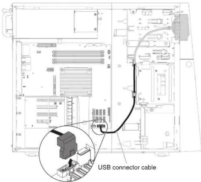
Figure 165. Front USB cableremoval for 5 User ver model with hot-swappowersupplies
-
Standtheserverbackupinitsverticalposition.
-
Removetheharddiskdrivefanduct(see"Removingtheharddiskdrivefanduct"onpage222).
-
PressdownandholdthereleasetabonthetopofthefrontUSBhousing; then,tiltthetopofthehousingawayfromthechassisandliftthehousingout
oftheopeninginthechassis.

Figure166. FrontUSBconnectorassemblyremovalfor5Uservermodelwithhot-swap powersupplies(1)
- SqueezethespringclipsonthesidesofthefrontUSBconnectorassemblyand pulltheassemblyoutofthebackofthehousing.
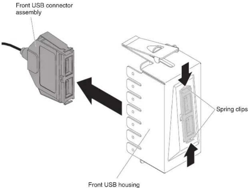
Figure167. FrontUSBconnectorassemblyremovalfor5Uservermodelwithhot-swap powersupplies(2)
- Carefully pull the front USB cable out of the opening in the chassis.
- If you are instructed to return the front USB connector assembly, follow all packaging instructions, and use an app packaging materials for shipping that are supplied to you.
ReplacingthefrontUSBconnectorassembly
UsethisinformationtoreplacethefrontUSBconnectorassembly
ToinstallthefrontUSBconnectorassemblyonthe4Uservermodelwith non-hot-swappowersupplies,completethefollowingsteps.For5Uservermodels withhot-swappowersupplies,pleaseseethenextsub-section.
- Readthesafetyinformationin"Safety"onpageviiand"Installation guidelines"onpage35.
- Carefully insert the front USB cable through the opening in the front of the chassis.
- PlacethetabonthebottomedgeoftheUSBhousingintothebottomofthe openinginthechassis.

Figure168.FrontUSBconnectorassemblyinstallationfor4Uservermodelwith non-hot-swappowersupplies
- TiltthetopoftheUSBhousingintopositiontotheend.
- SecurethefrontUSBhousingwiththescrew.
- RerouteandconnectthefrontUSBcabletothefrontUSBconnectoronthe systemboard(see"System-boardinternalconnectors"onpage30forthe locationofthefrontUSBconnector).
Note: Disconnection of the SATA cables is suggested if any of them interferes with the process.
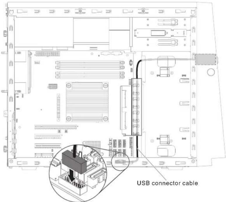
Figure169.FrontUSBcableinstallationfor4Uservermodelwithnon-hot-swappower supplies
- Installtheairbaffle(see"Replacingtheairbaffle"onpage185).
- Installthesidecover(see"Removingthesidecover" on page 38).
- Standtheserverbackupinitsverticalposition.
- Installbezel(see"Replacingthebezel"onpage188).
- Reconnecttheexternalcablesandpowercords;then,turnontheattached devicesandturnontheserver.
ToinstallthefrontUSBconnectorassemblyonthe5Uservermodelwithhot-swap powersupplies,completethefollowingsteps.For4Uservermodelswith non-hot-swappowersupplies,pleaseseetheabovesub-section.
- Readthesafetyinformationin"Safety"onpageviand"Installation guidelines"onpage35.
- Carefully insert the front USB cable through the opening in the front of the chassis.
- SqueezethespringclipsonthesidesofthefrontUSBconnectorassemblyand inserttheassemblyintothehousingthroughthebackofthehousing.
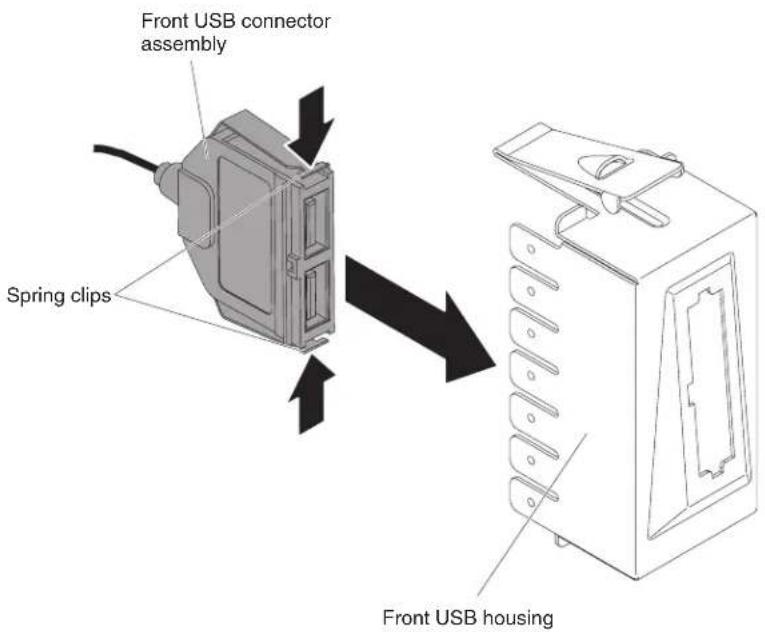
Figure170.FrontUSBconnectorassemblyinstallationfor5Uservermodelwithhot-swap powersupplies(1)
- Placethebottomedgeofthehousingintothebottomoftheopeninginthe chassis;then,tiltthetopofthehousingintopositionuntilitclicksintoplace.

Figure171.FrontUSBconnectorassemblyinstallationfor5Uservermodelwithhot-swap powersupplies(2)
- Carefullyturntheserveronitssidesothatitislyingflat,withthecover facingup.
Attention: Donotallowtheservertofallover.
- RerouteandconnectthefrontUSBcabletothefrontUSBconnectoronthe systemboard(see"System-boardinternalconnectors"onpage30forth locationofthefrontUSBconnector).
Note: Remembertoroutethecablingthroughthecableclips.

Figure 172. FrontUSBcableinstallationfor5Uservermodelwithhot-swappowersupplies
- Installtheharddiskdrivefanduct(see"Replacingtheharddiskdrivefanduct"onpage225).
- Standtheserverbackupinitsverticalposition.
- Installtheupperbezel(see"Replacingtheupperbezel"onpage192).
- Installthelowerbezel(see"Replacingthelowerbezel"onpage190).
- Installandlockthesidecover(see "Replacingthesidecover" on page 182).
- Reconnecttheexternalcablesandpowercords;then,turnontheattached devicesandturnontheserver.
Removingtherearadapterretentionbracket
Thisprocedureappliesonlytothe5Uservermodelwithhot-swappowersupplies.
Toremovetherearadapter-retentionbracketonthe5Uservermodelwith hot-swappowersupplies,completethefollowingsteps.
-
Turnoff the server and all attached devices; then, disconnect all power cords and external cables.
-
Unlockandremovethesidecover(see"Removingthesidecover" on page 38).
-
Carefullyturntheserveronitssidesothatitislyingflat,withthesystem boardfacingup.
Attention: Donotallowtheservertofallover.
- Removealladapters(ifnecessary)andplacetheadaptersonastatic-protective surface(see"Removinganadapter"onpage266).
Note: You might find the helpful to not where each adapter is installed before you remove the adapters.
-
Rotatetherearadapter-retentionbrackettotheopen(unlocked)position.
-
Graspthebracketononesideatthehingepointandpullinward(whileyou rotatethebracketslightlytowardthefrontoftheserver)untilthebracketis
freeofthehingepin;then,graspthebracketontheothersideatthehinge point,pullinwarduntilthebracketisfreeofthehingepin,andremovethe rearadapter-retentionbracketfromtheserver.
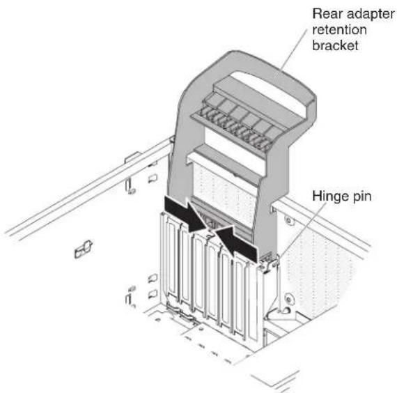
Figure173. Rearadapter-retentionbracketremovalfor5Uservermodelwithhot-swappower supplies
Replacingtherearadapterretentionbracket
Thisprocedureappliesonlytothe5Uservermodelwithhot-swappowersupplies.
Toinstalltherearadapter-retentionbracketonthe5Uservermodelwithhot-swap powersupplies,completethefollowingsteps.
- Readthesafetyinformationin"Safety"onpageviiand"Installation guidelines"onpage35.
- Positiontherearadapter-retentionbracketsothattheholeinoneofthehinge pointsisalignedwiththehingepinonthechassis;then,placethehingepin throughtheholeonthechassis.
- Rotatetherearadapter-retentionbracketintoplacesothattheholeinthe oppositheingepointsnapsintoplaceoverthehingepinonthechassis.

Figure174. Rearadapter-retentionbracketinstallationfor5Uservermodelwithhot-swap powersupplies
- Installheadapters.
- Standtheserverbackupinitsverticalposition.
- Installandlockthesidecover(see"Replacingthesidecover"onpage182).
- Reconnecttheexternalcablesandpowercords;then,turnontheattached devicesandturnontheserver.
Removingthenon-hot-swappowersupply
Thisprocedureappliesonlyto4Uservermodelswithnon-hot-swappower supplies.
When you remove or install a fixed powersupply, observ the following precautions.
Statement8

CAUTION:
Neverremovethecoveronapowersupplyoranypartthathasthefollowing labelattached.

Hazardousvoltage,current,andenergylevelsarepresentinsideanycomponent thatasthislabelattached.Therearenoserviceablepartsinsidethese components.Ifyoususpectaproblemwithoneoftheseparts,contactaservice technician.
Toremoveanon-hot-swappowersupplyon4Uservermodelswithnon-hot-swap powersupplies,completethefollowingsteps.
-
Readthesafetyinformationin"Safety"onpageviand"Installation guidelines"onpage35.
-
Turnoff the server and all attached devices; then, disconnect all power cords and external cables.
-
Carefullyturntheserveronitssidesothatitislyingflat, with theoverfacing up.
Attention: Donotallow the server to fallover.
-
Removethesidecover(see"Removingthesidecover" on page 38).
-
Removetheairbaffle(see"Removingtheairbaffle"onpage39).
-
Disconnecttheharddiskpowercablesfromthebackplate.
-
Disconnect the cables from the powersupply to the system board and all internal components. Not ether routing of all power-supply cables; you will need to order the power-supply cable the same way when you install the powersupply.
-
While you support the powersupply, remove the six screws that secure it to the chassis; then, lift the powersupply out of the chassis. Savethescrewsto use when you install there replacement powersupply.
Attention: It is important to support the powers supply while you remove the mountings screws. After all six screws are removed, the powers supply is loose and can damage other components in the server.

natural_image
Isometric technical diagram of a computer tower internal structure with no visible text or symbolsFigure 175. Non-hot-swappowersupplyscrewremovalfor4Uservermodelwith non-hot-swappowersupplies
Note: You may find it asiertoremovethe powersupply by pushing the bottom upward. Donotpull the cables.
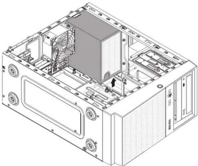
natural_image
Technical line drawing of a computer tower internal structure showing fan, drive, and ventilation components (no text or labels)Figure176.Non-hot-swappowersupplyremovalfor4Uservermodelwithnon-hot-swap powersupplies
- If you are instructed to return the powers supply, follow all packaging instructions, and use an y packaging materials for shipping that a resupplied to you.
Replacingthenon-hot-swappowersupply
Thisprocedureappliesonlyto4Uservermodelswithnon-hot-swappower supplies.
Statement8

CAUTION:
Neverremovethecoveronapowersupplyoranypartthathasthefollowing labelattached.

Hazardous voltage, current, and energy levels are present inside an component that has this label attached. There are no serviceable parts inside these components. If you suspect with one of these parts, contact a service technician.
Toinstallanon-hot-swappowersupplyon4Uservermodelswithnon-hot-swap powersupplies,completethefollowingsteps.
-
Readthesafetyinformationin"Safety"onpageviiand"Installation guidelines"onpage35.
-
Position the powers supply in the chassis so that the crew holes in the power supply are aligned with the corresponding holes in therear of the chassis.

natural_image
Isometric technical diagram of a computer tower internal structure with no visible text or symbolsFigure177.Non-hot-swappowersupplyinstallationfor4Uservermodelwithnon-hot-swap powersupplies(1)
Note: Makesurethetopandthebottomofthepowersupplyalignwiththe upperandlowertabsontheopening.

Figure178.Non-hot-swappowersupplyinstallationfor4Uservermodelwithnon-hot-swap powersupplies(2)
- Installthesixscrewstosecurethepowersupplytothechassis.
- Installtheairbaffle(see"Replacingtheairbaffle"onpage185).
- Installthesidecover(see "Replacingthesidecover" on page 182).
-
Standtheserverbackupinitsverticalposition.
-
Installthebezel(see "Replacingthebezel" on page 188).
- Reconnecttheexternalcablesandpowercords;then,turnontheattached devicesandturnontheserver.
Removingthehot-swappowersupply
Thisprocedureappliesonlytothe5Uservermodelwithhot-swappowersupplies.
When you remove or install a hot-swappowersupply, observ the following precautions.
Statement5

CAUTION:
The power control button on the device and the powers switch on the power supply on turn off the electrical currents supplied to the device. The device also might have more than one power cord. Toremove electrical current from the device, ensure that all power cords are disconnected from the powersource.

Statement8

CAUTION:
Neverremovethecoveronapowersupplyoranypartthathasthefollowing labelattached.

Hazardousvoltage,current,andenergylevelsarepresentinsideanycomponent thathasthislabelattached.Therearenoserviceablepartsinsidethese components.Ifyoususpectaproblemwithoneoftheseparts,contactaservice technician.
Attention: During normal operation, each power-supply bay must contain either a hot-swappowers supply or a hot-swappower-supply filler for proper cooling.
Toremoveahot-swappowersupplyonthe5Uservermodelwithhot-swappower supplies,completethefollowingsteps.
- Readthesafetyinformationin"Safety"onpageviand"Installation guidelines"onpage35.
- Disconnect the power cord from the powers supply that is to be removed.
- Pressdownontheorangereleaseleverandpullthepowersupplyoutofthe bay,usingthehandle.

Figure179. Hot-swappowersupplyremovalfor5Uservermodelwithhot-swappower supplies
- If you are instructed to return the powers supply, follow wall packaging instructions, and use an typ packaging materials for shipping that a resupplied to you.
Replacingthehot-swappowersupply
Thisprocedureappliesonlytothe5Uservermodelwithhot-swappowersupplies.
The following items describe the type of powersupply that the servers supports and other information that you must consider when you install powersupply:
•Toconfirmthattheserversupportsthepowersupplythatyouareinstalling,see http://www.ibm.com/systems/info/x86servers/serverproven/compat/us
- Theservercomesstandardwithone430-watthot-swappowersupply.Theinput voltageis110Vacor220Vacauto-sensing.
- Thesepowersuppliesaredesignedforparalleloperation.Intheeventofa power-supplyfailure,theredundantpowersupplycontinuestopowerthe system.Theserversupportsamaximumoftwopowersupplies.
- Theservercanrunfullyconfiguredwithonepowersupply.Forredundancy support,youmustinstallthesecondhot-swappowersupply.
Note: You cannot mix high-efficiency and non-high-efficiency powers supplies in the server.
Statement5

CAUTION:
rThepowercontrolbuttononthedeviceandthepowerswitchonthepower supplydonotturnofftheelectricalcurrentsuppliedtothedevice. Thedevice alsomighthavemorethanonepowercord. Toremoveallelectricalcurrentfrom thedevice,ensurethatallpowercordsaredisconnectedfromthepowersource.

Statement8

CAUTION:
Neverremovethecoveronapowersupplyoranypartthathasthefollowing labelattached.

Hazardousvoltage,current,andenergylevelsarepresentinsideanycomponent thathasthislabelattached.Therearenoserviceablepartsinsidethese components.Ifyoususpectawithoneoftheseparts,contactaservice technician.
Attention: During normal operation, each power-supply bay must contain either apowersupply or power-supply filler for proper cooling.
Toinstallahot-swappowersupplyonthe5Uservermodelwithhot-swappower supplies,completethefollowingsteps.
-
Readthesafetyinformationin"Safety"onpageviand"Installation guidelines"onpage35.
-
Placethepowersupplyintothebayguides.
-
Using the handle, push the powers supply toward the front of the chassis until it locks in to place.

Figure180. Hot-swappowersupplyinstallationfor5Uservermodelwithhot-swappower supplies
- Connectoneendofthepowercordintotheconnectoronthebackofthepower supplyandconnecttheotherendofthepowercordintoaproperlygrounded electricaloutlet.
- MakesurethatboththeacanddcpowerLEDsontherearofthepower supplyarelit, indicating that the powersupply is operating correctly.
Removinganadapter
Usethisinformationtoremoveanadapter
Toremoveanadapteron4Uservermodelswithnon-hot-swappowersupplies, completethefollowingsteps.Forthe5Uservermodelwithhot-swappower supplies,pleaseseethenextsub-section.
- Readthesafetyinformationin"Safety"onpageviiand"Installation guidelines"onpage35.
- Turnoff the server and all peripheral devices; then, disconnect the power cords and all external cables.
-
Carefullyturntheserveronitssidesothatitislyingflat,withthecover facingup.
Attention: Donotallowtheservertofallover. -
Removethesidecover(see"Removingthesidecover"onpage38).
-
Removetheairbaffle(see"Removingtheairbaffle"onpage39).
-
Disconnectanycablesfromtheadapteroranycablesthatimpedeaccessto theServeRAIDadapter.
-
Lifttheendoftherearadapterretentionbrackettillthetabdisengagesthe holeonthechassis.

natural_image
Technical diagram of a computer motherboard showing internal components and wiring (no text or labels)Figure 181. Rearadapterretentionbracketremovalfor4Uservermodelwithnon-hot-swap powersupplies
-
Removetheexpansion-slotscrewattherearoftheadapterifany.
-
Carefullygrasptheadapterbyitstopedgeoruppercorners;then,pullthe adaptertoremoveitfromtheserver.
Attention: Expansion-slotcoversmustbeinstalledinallemptyslots. This maintains the electronic emissions standards of the computer and ensures proper ventilation of computer components.

Figure182. Adapterremovalfor4Uservermodelwithnon-hot-swappowersupplies
-
If you are not replacing the adapter, install an expansion-slot cover in the expansion-slot opening.
-
If you are instructed to return the adapter, follow all packaging instructions, and use an app packaging materials for shipping that a resupplied to you.
Toremoveanadapteronthe5Usermodelwithhot-swappowersupplies, completethefollowingsteps.For4Uservermodelswithnon-hot-swappower supplies,pleaseseetheabovesub-section.
-
Readthesafetyinformationin"Safety"onpageviiand"Installation guidelines"onpage35.
-
Turnoff the server and all attached devices; then, disconnect all power cords and external cables.
-
Unlockandremovethesidecover(see"Removingthesidecover" onpage38).
-
Carefullyturntheserveronitssidesothatitislyingflat,withthesystem boardfacingup.Donotallowtheservertofallover.
Attention: Donotallow the server to fallover.
-
Disconnectanycablesfromtheadapteroranycablesthatimpedeaccesstothe adapter.
-
Rotatetherearadapter-retentionbrackettotheopen(unlocked)position.
-
Carefullygrasptheadapterbyitstopedgeoruppercorners, andpullthe adapterfromtheserver.
Attention: Expansion-slotcoversmustbeinstalledinallemptyslots. This maintains the electronic emissions standards of the computer and ensures proper ventilation of computer components.

Figure183. Adapterremovalfor5Uservermodelwithhot-swappowersupplies
-
If you are not replacing the adapter, install an expansion-slot cover in the expansion-slot opening.
-
If you are instructed to return the adapter, follow all packaging instructions, and use an y packaging materials for shipping that a resupplied to you.
Replacinganadapter
Usethisinformationtoreplaceanadapter
Attention: When installing the Intel x520 Dual Port 10 Gb ESFP + adapter (option part number is 49 Y7960), the maximum number that can be installed in the server istwo.
Forthelocationsoftheexpansionslotsandconnectors,pleasesee"System-board internalconnectors"onpage30.
Toinstallareplacementadapteron4Uservermodelswithnon-hot-swappower supplies,completethefollowingsteps.Forthe5Uservermodelwithhot-swap powersupplies,pleaseseethenextsub-section.
- Readthesafetyinformationin"Safety"onpageviiand"Installation guidelines"onpage35.
- Check the instruction that comewith the adapter for any requirements, restrictions, or cabling instructions. It might be easier to route cables before you install the adapter.
- Follow the instruction that comewith the adapter to set jumpers or switches, if any.
- Touchthestatic-protectivepackagethatcontainstheadaptertoanyunpainted metalsurfaceontheserver.Then,removetheadapterfromthe static-protectivepackage.Avoidtouchingthecomponentsandgold-edge connectorsontheadapter.
- Followthecablinginstructions,ifany,thatcomewiththeadapter.Routethe adaptercablesbeforeyouinstalltheadapter.
- Follow the instruction that comewith the adapter to set jumpers or switches, if any.
- Removetheexpansion-slotcoverbyunscrewingthescrewthatsecuresitto thechassis.Storetheexpansion-slotcoverandscrewinasafeplaceforfuture use.
Note: Expansion-slotcoversmustbeinstalledonallvacantslots. This maintains the electronicemissions standard of the server and ensures proper ventilation of server components.
- Carefullygrasptheadapterbythetopedgeoruppercorners, and alignit with the expansionslotguides; then, presstheadapterfirmly into the expansionslot.
Attention: Makesurethattheadapteriscorrectlyseatedintheexpansion slotbeforeyouturnontheserver.Incompleteinstallationofanadaptermight damagethesystemboardortheadapter.

Figure 184. Adapter installation for 4User vermodel with non-hot-swappowersupplies
- Positiontherearadapterretentionbracketsothattheholeinoneofthehinge pointsisalignedwiththehingepinonthechassis;then,placethehingepin throughtheholeonthechassis.

natural_image
Technical diagram of a computer motherboard showing internal components and a close-up inset of a pipe fitting (no text or symbols)Figure185. Rearadapterretentionbracketinstallationfor4Uservermodelwithnon-hot-swap powersupplies
-
Rotatetherearadapterretentionbracketintoplacesothattheholeinthe oppositehingepointsnapsintoplaceoverthehingepinonthechassis.
-
Connectanyrequiredcablestotheadapter.Routethecablessothattheydo notblocktheflowofairfromthesystemfan.
- Installtheairbaffle(see"Replacingtheairbaffle"onpage185).
- Installthesidecover(see "Replacingthesidecover" on page 182).
- Standtheserverbackupinitsverticalposition.
- Installthebezel(see"Replacingthebezel"onpage188).
- Reconnecttheexternalcablesandpowercords;then,turnontheattached devicesandturnontheserver.
Toinstallareplacementadapteronthe5Uservermodelwithhot-swappower supplies,completethefollowingsteps.For4Uservermodelswithnon-hot-swap powersupplies,pleaseseetheabovesub-section.
- Readthesafetyinformationin"Safety"onpageviiand"Installation guidelines"onpage35.
- Check the instruction that comewith the adapter for any requirements, restrictions, or cabling instructions. It might be easier to route cables before you install the adapter.
- Follow the instruction that comewith the adapter to set jumpers or switches, if any.
- Touchthestatic-protectivepackagethatcontainstheadaptertoanyunpainted metalsurfaceontheserver.Then,removtheadapterfromthe static-protectivepackage.Avoidtouchingthecomponentsandgold-edge connectorsontheadapter.
- Turnoff the server and all peripheral devices; then, disconnect the power cords and all external cables.
- Removetheexpansion-slotcoverbyunscrewingthescrewthatsecuresitto thechassis.Storetheexpansion-slotcoverandscrewinasafeplaceforfuture use.
Note: Expansion-slotcoversmustbeinstalledonallvacantslots. This maintains the electronicemissions standards of the server and ensures proper ventilation of server components.
- Carefullygrasptheadapterbythetopedgeoruppercorner,andmovethe adapterdirectlyfromthestatic-protectivepackagetotheexpansionslot.Align theadapterwiththeexpansionslotguides;then,presstheadapterfirmlyinto theexpansionslot.
Attention: Makesurethattheadapteriscorrectlyseatedintheexpansion slotbeforeyouturnontheserver.Incompleteinstallationofanadaptermight damagethesystemboardortheadapter.

Figure186. Adapterinstallationfor5Uservermodelwithhot-swappowersupplies
- Connecttherequiredcablestotheadapter.Routecablessothattheydonot blocktheairflowfromthefan.
- Rotatetherearadapter-retentionbrackettotheclosed(locked)position.
- Standtheserverbackupinitsverticalposition.
- Installandlockthesidecoversee"Replacingthesidecover"onpage182).
- Reconnecttheexternalcablesandpowercords;then,turnontheattached devicesandturnontheserver.
Removingamemorymodule
Usethisinformationtoremoveamemorymodule.
Toremoveadualinlinememorymodule(DIMM)on4Uservermodelswith non-hot-swappowersupplies,completethefollowingsteps.Forthe5Userver modelwithhot-swappowersupplies,pleaseethenextsub-section.
- Readthesafetyinformationin"Safety"onpageviiand"Installation guidelines"onpage35.
- Turnoff the server and all attached devices; then, disconnect all power cords and external cables.
- Carefully turn the server on its sides that it is lying flat, with the cover facing up.
Attention: Donotallowtheservertofallover.
- Removethesidecover(see"Removingthesidecover" on page 38).
- Removetheairbaffle(see"Removingtheairbaffle" on page39).
- LocatetheDIMMconnectorthatcontainstheDIMMthatistobereplaced(see "System-boardinternalconnectors" onpage30).
Attention: To avoid breaking the DIMM retaining clips or damaging the DIMM connectors, open and closethe clips gently.
- CarefullyopentheretainingclipsoneachendoftheDIMMconnectorand removetheDIMM.

Figure187.DIMMremoval
- If you are instructed to return the DIMM, follow wall packaging instructions, and use an y packaging materials for shipping that a resupplied to you.
Toremoveadualinlinememorymodule(DIMM)onthe5Uservermodelwith hot-swappowersupplies,completethefollowingsteps.For4Uservermodelswith non-hot-swappowersupplies,pleaseseetheabovesub-section.
-
Readthesafetyinformationin"Safety"onpageviiand"Installation guidelines"onpage35.
-
Turnoff the server and all attached devices; then, disconnect all power cords and external cables.
-
Unlockandremovethesidecover(see"Removingthesidecover" onpage38).
-
Carefullyturntheserveronitssidesothatitislyingflat,withthecoverfacing up.
Attention: Donotallowtheservertofallover.
- LocatetheDIMMconnectorthatcontainstheDIMMthatistobereplaced(see "System-boardinternalconnectors" onpage30).
Attention: To avoid breaking the DIMM retaining clips or damaging the DIMM connectors, open and closethe clips gently.
- CarefullyopentheretainingclipsoneachendoftheDIMMconnectorand removetheDIMM.
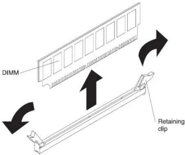
Figure188.DIMMremoval
- If you are instructed to return the DIMM, follow wall packaging instructions, and use an y packaging materials for shipping that a resupplied to you.
Replacingamemorymodule
Usethisinformationtoreplaceamemorymodule
The following notes describe the types of dual in line memory modules (DIMMs) that the servers supports and other information that you must consider when you install DIMMs (see "System-board internal connectors" on page 30).
If you are replacing a drive, makes sure that:
- Theserversupportsindustry-standard,1066,1333and1600MHz,PC3-12800 (single-rankordual-rank)double-data-rate3(DDR3),registeredorunbuffered, synchronousdynamicrandom-accessmemory(SDRAM)dualinlinememory modules(DIMMs)witherrorcorrectingcode(ECC).Foralistofsupported optionsfortheserver,seehttp://www.ibm.com/systems/info/x86servers/serverproven/compat/us;then,selectyourcountryandnavigatetothelistof optionsfortheserver.
- Themaximumamountofmemorythattheserversupportsisdependentonthe typeofmemorythatyouinstallintheserver.
•Theamountofusablememoryisreduced,dependingonthesystem configuration.Acertainamountofmemorymustbereservedforsystem resources.Toviewthetotalamountofinstalledmemoryandtheamountof configuredmemory,runtheSetuputility.Foradditionalinformation,seeUsing theSetuputility.
- Themaximumoperatingspeedoftheserverisdeterminedbytheslowest DIMMintheserver.
- If you install a pair of DIMMs in DIMM connectors 1 and 3, the size and speed of the DIMM that you install in DIMM connectors 1 and 3 must match each other. However, they donothavetobethesame size and speed as the DIMMs that are installed in DIMM connectors 2 and 4.
- YoucanusecompatibleDIMMsfromvariousmanufacturersinthesamepair.
- WhenyouinstallorremoveDIMMs, theserverconfigurationinformation changes. Whenyourestarttheserver, thesystemdisplaysamessagethat indicate that the memory configuration has changed. Staticelectricity thatis
released to internal server components when the server is powered on might cause the server to stop, which could result in the loss of data. To avoid this potential problem, always use an electrostatic-discharge wrist strap or other grounding system when working inside the server with the poweron.
Attention: Staticelectricity that is released to internal server components when the server is powered on might cause the server vertostop, which could result in the loss of data. To avoid this potential problem, always use an electrostatic-discharge wrist strap or other groundings system when working inside the server with the poweron.
- ThespecificationsofaDDR3DIMMareonalabelontheDIMM,inthe followingformat.
ggg eRxff-PC3-wwwwwm-aa-bb-cc
where:
-gggisthetotalcapacityoftheDIMM(forexample,1GB,2GB,or4GB)
-eisthenumberofranks
-1=single-rank
-2=dual-rank
-4=quad-rank
-ffisthedeviceorganization(bitwidth)
-4=x4organization(4DQlinesperSDRAM)
-8=x8organization
-16=x16organization
- wwwwwistheDIMMbandwidth, in MBps
-8500=8.53GBps(PC3-1066SDRAMs,8-byteprimarydatabus)
-10600=10.66GBps(PC3-1333SDRAMs,8-byteprimarydatabus)
-12800=12.8GBps(PC3-1600SDRAMs,8-byteprimarydatabus)
-mistheDIMMtype
-E=UnbufferedDIMM(UDIMM)withECC(x72-bitmoduledatabus)
-R=RegisteredDIMM(RDIMM)
-U=UnbufferedDIMMwithnoECC(x64-bitprimarydatabus)
-aaistheCASlatency,inclocksatmaximumoperatingfrequency
-bbistheJEDECSPDRevisionEncodingandAdditionslevel
-ccisthereferencedesignfileforthedesignoftheDIMM
-distherevisionnumberofthereferencedesignoftheDIMM
Note: TodeterminethetypeofaDIMM, seethelabelontheDIMM. The informationonthelabelisintheformatxxxxxnRxxxPC3-xxxxx-xx-xx-xxx. The numeralinthesixthnumericalpositionindicateswhethertheDIMMis single-rank(n=1)ordual-rank(n=2).
UnbufferedDIMMs(UDIMMs):
The following notes provide information that you must consider when you install UDIMMs:
- ThememorychannelsrunatthelowestcommonfrequencyoftheDIMMs installed.
•TheUDIMMoptionsthatareavailablefortheserverare1GB,2GB,4GB,and 8GB(whenavailable)DIMMs. - Theserversupportsuptotwosingle-rankordual-rankUDIMMsperchannel.
The following table lists supported UDIMM population.
Table35.SupportedUDIMMpopulationperchannel
| DIMM connectorsper channel | DIMMs installedineach channelDIMMtype | DIMMspeed | Ranksper DIMM(any combination) | |
| 21Unbuffered | DDR3ECC | 1333,1600Single-rank,dual-rank | ||
| 22Unbuffered | DDR3ECC | 1333,1600Single-rank,dual-rank | ||
The following table lists the maximum DIMM population using ranked UDIMMs.
Table36.MaximummemorypopulationusingrankedUDIMMs(dependingonyourmodel)
| Numberof UDIMMsDIMMtype | SizeTotalmemory | ||
| 4Single-rankUDIMMs1 | GB | 4GB | |
| 4Dual-rankUDIMMs | 2GB | 8GB | |
| 4Dual-rankUDIMMs | 4GB | 16GB | |
| 4Dual-rankUDIMMs | 8GB(when available) | 32GB | |
The following tables show the UDIMM memory population rule to optimize the system performance.
Table37.UDIMMpopulationrule
| DIMM connector 1 | DIMM connector 2 | DIMM connector 3 | DIMM connector 4 |
| Populated | Empty | Empty | Empty |
| Populated | Empty | Populated | Empty |
| Populated | Populated | Populated | Populated |
The following illustrations show the location of the DIMM connectors on the systemboard.
Note: The illustrations in this document might differ slightly from your model.
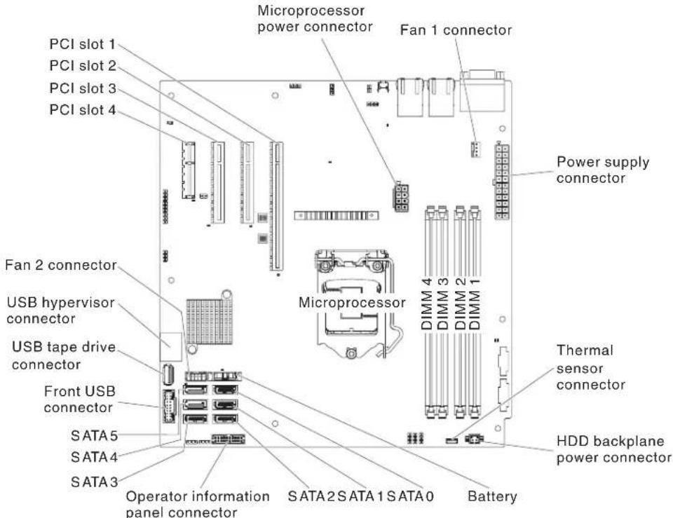
Figure189.DIMMconnectorsonsystemboard
Attention: Staticelectricity that is released to internal server components when the server is powered on might cause the server to hold, which might result in the loss of data. To avoid this potential problem, always use an electrostatic discharge wrist strap or other groundings system when you work inside the server with the poweron.
ToinstallaDIMMon4Usermodelswithnon-hot-swappowersupplies, completethefollowingsteps.Forthe5Usermodelwithhot-swappower supplies,pleaseseethenextsub-section.
-
Readthesafetyinformationin"Safety"onpageviand"Installation guidelines"onpage35.
-
LocatetheDIMMconnectorsonthesystemboard.Determinetheconnectors intowhichyouwillinstalltheDIMMs.InstalltheDIMMsinthesequence showninthefollowingtable.
Table38.DIMMinstallationsequence
| NumberofDIMMsInstallationsequence(connectors) | |
| FirstpairofDIMMs1,3 | |
| SecondpairofDIMMs2,4 | |
- Opentheretainingclipsand,ifnecessary,removeanyexistingDIMM. Attention:ToavoidbreakingtheretainingclipsordamagingtheDIMM connectors,openandclosetheclipsgently.

Figure190.DIMMinstallation
- Touchthestatic-protectivepackagethatcontainstheDIMMtoanyunpainted metalsurfaceontheoutsideoftheserver.Then,removetheDIMMfromthe package.
- TurntheDIMMsothattheDIMMkeysaligncorrectlywiththeconnector.
- InserttheDIMMintotheconnectorbyaligningtheedgesoftheDIMMwith theslotsattheendsoftheDIMMconnector.
- Firmlypress the DIMM straightdown into the connector by applying pressure on both end of the DIMMs simultaneously. Theretainingclipssnap into the locked position when the DIMMis firmly seated in the connector.
Note: If thereisagapbetween the DIMM and theretaining clips, the DIMM has not been correctly inserted; open theretaining clips, remove the DIMM, and then reinsert it.
- Installtheairbaffle(see"Replacingtheairbaffle"onpage185).
- Installthesidecover(see "Replacingthesidecover" on page 182).
- Standtheserverbackupinitsverticalposition.
- Installthebezel(see"Replacingthebezel"onpage188).
- Reconnecttheexternalcablesandpowercords;then,turnontheattached devicesandturnontheserver.
ToinstallaDIMMonthe5Uservermodelwithhot-swappowersupplies, completethefollowingsteps.For4Uservermodelswithnon-hot-swappower supplies,pleaseseetheabovesub-section.
- Readthesafetyinformationin"Safety"onpageviiand"Installation guidelines"onpage35.
- LocatetheDIMMconnectorsonthesystemboard.Determinetheconnectors intowhichyouwillinstalltheDIMMs.InstalltheDIMMsinthesequence showninthefollowingtable.
Table39.DIMMinstallationsequence
| NumberofDIMMsInstallationsequence(connectors) | |
| FirstpairofDIMMs1,3 | |
| SecondpairofDIMMs2,4 | |
- Opentheretainingclipsand,ifnecessary,removeanyexistingDIMM. Attention:ToavoidbreakingtheretainingclipsordamagingtheDIMM connectors,openandclosetheclipsgently.

Figure191.DIMMinstallation
- Touchthestatic-protectivepackagethatcontainstheDIMMtoanyunpainted metalsurfaceontheserver.Then,removethenewDIMMfromthepackage.
- TurntheDIMMsothattheDIMMkeysaligncorrectlywiththeconnector.
- InserttheDIMMintotheconnectorbyaligningtheedgesoftheDIMMwith theslotsattheendsoftheDIMMconnector.FirmlypresstheDIMMstraight downintotheconnectorbyapplyingpressureonbothendsoftheDIMM simultaneously.Theretainingclipssnapintothelockedpositionwhenthe DIMMisfirmlyseatedintheconnector.IfthereisagapbetweentheDIMM andtheretainingclips,theDIMMhasnotbeencorrectlyinstalled.Openthe retainingclips,removetheDIMM,andthenreinsertit.
- Standtheserverbackupinitsverticalposition.
- Installandlockthesidecover(see "Replacingthesidecover" on page 182).
- Reconnecttheexternalcablesandpowercords;then,turnontheattached devicesandturnontheserver.
Removingthesystembattery
Usethisinformationtoremoveasystembattery.
The following notes describe information that you must consider when replacing the battery:
- IBMhasdesignedthisproductwithyoursafetyinmind.Thelithiumbattery mustbehandledcorrectlytoavoidpossibledanger.Ifyoureplacethebattery, youmustadheretothefollowinginstructions.
Note: In the U.S., call 1-800-IBM-4333 for information about battery disposal.
- If you're placethe original lithium battery with a heavy-metal battery or a battery with heavy-metal components, be aware of the following environmental consideration. Batteries and accumulator that contain heavy metals must not be disposed of with normal domestic waste. They will be taken back free of charge by the manufacturer, distributor, or representative, to be recycled or disposed of inapopermanner.
•Toorderreplacementbatteries,call1-800-IBM-SERVwithintheUnitedStates, and1-800-465-7999or1-800-465-6666withinCanada.OutsidetheU.S.and Canada,callyoursupportcenterorbusinesspartner.
Note: After you replace the battery, you must reconfigure the server and reset the system date and time.
Statement2

CAUTION:
When replacing the lithium battery, use only IBMPartNumber33F8354oran equivalent type battery recommended by the manufacturer. If your system has a module containing alithium battery, replace it only with the samemodule typemade by the samemanufacturer. The battery contains lithium and can explode if not properly used, handled, or disposed of.
Donot:
-Throworimmerseintowater
-Heattomorethan100°C(212°F)
-Repairordisassemble
Disposeofthebatteryasrequiredbylocalordinancesorregulations.
Toremovethebatteryonthe4Uservermodelwithnon-hot-swappowersupplies, completethefollowingsteps.Forthe5Uservermodelwithhot-swappower supplies,pleaseseethenextsub-section.
-
Readthesafetyinformationin"Safety"onpageviand"Installation guidelines"onpage35.
-
Turnoff the server and all attached devices; then, disconnect all power cords and external cables.
-
Carefullyturntheserveronitssidesothatitislyingflat, with theoverfacing up.
Attention: Donotallowtheservertofallover.
-
Removethesidecover(see"Removingthesidecover" on page38).
-
Removetheairbaffle(see "Removingtheairbaffle" on page39).
-
Locatethebatteryonthesystemboard(see"System-boardinternalconnectors" onpage30).
-
Removethebattery:
a. Useonefingertotiltthebatteryhorizontallyoutofitssocket,pushingit awayfromthesocket.
b. Liftandremovethebatteryfromthesocket.
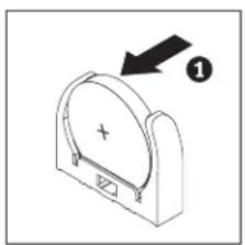
natural_image
Simple line drawing of a mechanical component with an arrow and label (no text or symbols)
Figure192. System battery removal for 4 User model with non-hot-swappowers supplies
Toremovethebatteryonthe5Uservermodelwithhot-swappowersupplies, completethefollowingsteps.For4Uservermodelswithnon-hot-swappower supplies,pleaseseetheabovesub-section.
-
Readthesafetyinformationin"Safety"onpageviand"Installation guidelines"onpage35.
-
Turnoff the server and all attached devices; then, disconnect all power cords and external cables.
-
Unlockandremovethesidecover(see "Removingthesidecover" on page 38).
-
Carefullyturntheserveronitssidesothatitislyingflat,withthecoverfacing up.
Attention: Donotallowtheserverterofallover.
-
Locatethebatteryonthesystemboard(see "System-boardinternalconnectors" onpage30).
-
Removethebattery:
a. Useonefingertotiltthebatteryhorizontallyoutofitssocket,pushingit awayfromthesocket.
b. Liftandremovethebatteryfromthesocket.
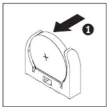

Figure193. System battery removal for 5 User model with hot-swappowersupplies
Replacingthesystembattery
Usethisinformationoreplacethesystembattery
The following notes describe information that you must consider when replacing the system-board battery in the server.
- Whenreplacingthesystem-boardbattery,youmustreplaceitwithalithium batteryofthesametypefromthesamemanufacturer.
•Toorderreplacementbatteries,call1-800-426-7378withintheUnitedStates,and 1-800-465-7999or1-800-465-6666withinCanada.OutsidetheU.S.andCanada, callyourIBMmarketingrepresentativeorauthorizedreseller.
- Afteryoureplacethesystem-boardbattery,youmustreconfiguretheserverandresetthesystemdateandtime.
•To avoid possible danger, read and follow the following safety statement.
Statement2

CAUTION:
Whenreplacingthelithiumbattery,useonlyIBMPartNumber33F8354oran equivalenttypebatteryrecommendedbythemanufacturer.Ifyoursystemhasa modulecontainingalithiumbattery,replaceitonlywiththesamemoduletype madebythesamemanufacturer.Thebatterycontainslithiumandcanexplodeif notproperlyused,handled,ordisposedof.
Donot:
- Throworimmerseintowater
•Heattomorethan100°C(212°F)
•Repairordisassemble
Disposeofthebatteryasrequiredbylocalordinancesorregulations.
Toinstallthereplacementbatteryonthe4Uservermodelwithnon-hot-swap powersupplies,completethefollowingsteps.Forthe5Uservermodelwith hot-swappowersupplies,pleaseseethenextsub-section.
- Readthesafetyinformationin"Safety"onpageviiand"Installation guidelines"onpage35.
- Followanyspecialhandlingandinstallationinstructionsthatcomewiththe replacementbattery.
- Insertthebattery:
a. Holdthebatteryinaverticalorientationsothatthesmallersideisfacing thesocket.
b. Tiltthebatteryandslidethebatteryintoitssocket;then,pressthebattery towardthesocketuntilitclicksintoplace.Makesurethatthebatteryclip holdsthebatterysecurely.
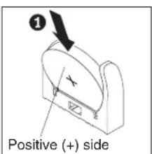

natural_image
Simple line drawing of a mechanical component with an arrow and plus sign, no text or symbols present.Figure 194. System battery installation for 4 User model with non-hot-swappowersupplies
- Installtheairbaffle(see "Replacingtheairbaffle" on page 185).
- Installthesidecover(see "Replacingthesidecover" on page 182).
- Standtheserverbackupinitsverticalposition.
- Reconnecttheexternalcablesandpowercords;then,turnontheattached devicesandturnontheserver.
-
StarttheConfiguration/SetupUtilityprogramandresettheconfiguration:
-
Setthesystemdateandtime.
- Setthepower-onpassword.
•Reconfiguretheserver.
See "Setuputilitymenuchoices" on page 99 for details.
Toinstallthereplacementbatteryonthe5Uservermodelwithhot-swappower supplies,completethefollowingsteps.For4Uservermodelswithnon-hot-swap powersupplies,pleaseseetheabovesub-section.
- Readthesafetyinformationin"Safety"onpageviiand"Installation guidelines"onpage35.
- Followanyspecialhandlingandinstallationinstructionsthatcomewiththe replacementbattery.
- Insertthebattery:
a. Orientthebatterysothatthepositivesidefacesup.
b. Tiltthebatteryandslidethebatteryintoitssocket.


natural_image
Simple line drawing of a mechanical component with an arrow and plus sign, no text or symbols present.Figure195. System battery installation for 5User model with hot-swappowersupplies
c. Pressthebatterydownintothesocketuntilitclicksintoplace.Makesure thatthebatteryclipholdsthebatterysecurely.
- Standtheserverbackupinitsverticalposition.
- Installandlockthesidecover(see "Replacingthesidecover" on page 182).
- Reconnecttheexternalcablesandpowercords;then,turnontheattached devicesandturnontheserver.
- StarttheConfiguration/SetupUtilityprogramandresettheconfiguration:
- Setthesystemdateandtime.
- Setthepower-onpassword.
•Reconfiguretheserver.
See "Setuputilitymenuchoices" on page 99 for details.
Removingtherearsystemfan
Thisprocedureappliesonlyto4Uservermodelswithnon-hot-swappower supplies.
Toremovetherearsystemfanonthe4Uservermodelwithnon-hot-swappower supplies,completethefollowingsteps.
- Turnoff the server and all attached devices; then, disconnect all power cords and external cables.
- Carefullyturntheserveronitssidesothatitislyingflat, with theoverfacing up.
Attention: Donotallowtheservertofallover.
- Removethesidecover(see "Removingthesidecover" on page 38).
- Removetheairbaffle(see "Removingtheairbaffle" on page 39).
- Removeanyadaptersthatimpedeaccesstothefanandthefanconnectoron thesystemboard(see"Removinganadapter"onpage266).
- Removethesystemfan:
a. Disconnectthefancablefromthesystemboard(see"System-boardinternal connectors"onpage30).
b. Whileyousupportthesystemfanwithonehand,pulltherubbergrommet awayfromthechassistomakeitthinner;then,pullthefantowardthefront oftheservertoremovetherubbergrommetthroughtheholeonthe chassis.Repeatthissteptillalltheremainingrubbergrommetsare removed.
c. Liftthesystemfanupandoutofthechassis.

Figure196. Systemfanremovalfor4Uservermodelwithnon-hot-swappowersupplies
- If you are instructed to return the fan, follow all packaging instructions, and use any packaging materials for shipping that a resupplied to you.
Replacingtherearsystemfan
Thisprocedureappliesonlyto4Uservermodelswithnon-hot-swappower supplies.
Attention: To ensure proper cooling and airflow, donotoperatetheserver for more than 30 minutes with the side cover removed.
Toinstalltherearsystemfanonthe4Uservermodelwithnon-hot-swappower supplies,completethefollowingsteps.
-
Readthesafetyinformationin"Safety"onpageviiand"Installation guidelines"onpage35.
-
Thereplacementfancomeswiththerubbergrommetsinstalled;however,they mighthavecomeoutduringshipment.Ifanyoftherubbergrommetsare missingfromthefan,installthemonthefanbeforeyoucontinue.Use needle-nosedplierstopullthegrommetsthroughtheholesinthefan.
-
Positionthefansothatthegrommetsprotrudethroughtheholesinthechassis; then,useneedle-nosedplierstopullthegrommetsthroughtheholesfrom outsidethechassis.

Figure 197. Systemfaninstallationfor4Uservermodelwithnon-hot-swappowersupplies(1)

Figure198. Systemfaninstallationfor4Uservermodelwithnon-hot-swappowersupplies(2)
-
Connectthefancabletothesystemboard(see "System-boardinternal connectors" onpage30forthelocationoftherearfanconnector).
-
Installanyadaptersthatyouremoved(see"Replacinganadapter"onpage 269).
-
Installtheairbaffle(see"Replacingtheairbaffle"onpage185).
- Installthesidecover(see "Replacingthesidecover" on page 182).
- Standtheserverbackupinitsverticalposition.
- Reconnecttheexternalcablesandpowercords;then,turnontheattached devicesandturnontheserver.
Removingthethermalsolutionfankit
Usethisinformationtoremovethethermalsolutionfankit
Toremovethethermalsolutionfankitonthe4Uservermodelwithnon-hot-swap powersupplies,completethefollowingsteps.For5Uservermodelswithhot-swap powersupplies,pleaseseethenextsub-section.
- Readthesafetyinformationin"Safety"onpageviiand"Installation guidelines"onpage35.
- Turnoff the server and all attached devices; then, disconnect all power cords and external cables.
- Carefullyturntheserveronitssidesothatitislyingflat, with theoverfacing up.
Attention: Donotallowtheservertofallover.
- Removethesidecover(see"Removingthesidecover"onpage38).
- Removetheairbaffle(see"Removingtheairbaffle"onpage39).
- Removethethermalsolutionfankit:

Figure 199. Thermalsolutionfankitremovalfor4Uservermodelwithnon-hot-swappower supplies
a. Disconnect the fancable from the system board (see "System-board internal connectors" on page 30).
b. While you support the system fan with one hand, pull the rubber grommet away from the chassis make it thinner; then pull the front forward the front of the server to remove the rubber grommet through the hole on the chassis. Repeat this step till all their remaining rubber grommets are removed.
c. Liftthesystemfanupandoutofthechassis.
- If you are instructed to return the thermals solution fankit, follow all packaging instructions, and use any packaging materials for shipping that aresupplied to you.
Toremovethethermalsolutionfankitonthe5Uservermodelwithhot-swap powersupplies,completethefollowingsteps.For4Uservermodelswith non-hot-swappowersupplies,pleaseseetheabovesub-section.
-
Readthesafetyinformationin"Safety"onpageviiand"Installation guidelines"onpage35.
-
Turnoff the server and all attached devices; then, disconnect all power cords and external cables.
-
Unlockandremovethesidecover(see"Removingthesidecover" onpage38).
-
Carefullyturntheserveronitssidesothatitislyingflat,withthecoverfacing up.
Attention: Donotallowtheservertofallover.
- Removethethermalsolutionfankit:

Figure200. Thermalsolutionfankitremovalfor5Uservermodelwithhot-swappower supplies
a. Disconnectthefancablefromthesystemboard(see"System-boardinternal connectors"onpage30).
b. Graspthesystemfanbythebluepointandpulluptoliftitoutofthe chassis.
- If you are instructed to return the thermals solution fankit, follow wall packaging instructions, and use an y packaging materials for shipping that a resupplied to you.
Replacingthethermalsolutionfankit
Usethisinformationoreplacethethermalsolutionfankit
Attention:
- Toensurepropercoolingandairflow,donotoperatetheserverformorethan 30minuteswiththesidecoverremoved.
- When you install second adapter in the headapters slot on the system board, you must install the IBM Thermal Solution Fankit option to ensure proper cooling and airflow to the system. For 4 User models with non-hot-swaps powers supplies, the part number is 46 W 9177. For 5 User models with hot-swaps powers supplies, the part number is 00 Y 8200.
Toinstallthethermalsolutionfankitonthe4Uservermodelwithnon-hot-swap powersupplies,completethefollowingsteps.For5Uservermodelswithhot-swap powersupplies,pleaseseethenextsub-section.
- Readthesafetyinformationin"Safety"onpageviiand"Installation guidelines"onpage35.
- Insertthethermalsolutionfankit:
a. Graspthesystemfanbythebluepointandloweritintotheserver, making sureitlatchesontothechassis.
b. Connectthefancabletothesystemboard(see"System-boardinternal connectors"onpage30).

Figure201. Thermalsolutionfankitinstallationfor4Uservermodelwithnon-hot-swappower supplies
- Installtheairbaffle(see"Replacingtheairbaffle"onpage185).
- Installthesidecover(see"Replacingthesidecover"onpage182).
- Standtheserverbackupinitsverticalposition.
- Reconnecttheexternalcablesandpowercords;then,turnontheattached devicesandturnontheserver.
Toinstallthethermalsolutionfankitonthe5Uservermodelwithhot-swap powersupplies,completethefollowingsteps.For4Uservermodelswith non-hot-swappowersupplies,pleaseseetheabovesub-section.
-
Readthesafetyinformationin"Safety"onpageviiand"Installation guidelines"onpage35.
-
Insertthethermalsolutionfankit:
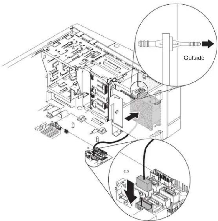
Figure202. Thermalsolutionfankitinstallationfor5Uservermodelwithhot-swappower supplies
a. Positionthefansothatthegrommetsprotrudethroughtheholesinthe chassis;then,useneedle-nosedplierstopullthegrommetsthroughthe holesfromoutsidethechassis.
b. Connectthefancableintothesystemboard(see"System-boardinternal connectors"onpage30).
-
Standtheserverbackupinitsverticalposition.
-
Installandlockthesidecover(see"Replacingthesidecover"onpage182).
-
Reconnecttheexternalcablesandpowercords;then,turnontheattached devicesandturnontheserver.
Removingtheoperatingtemperatureenhancementkit
Usethisinformationtoremovetheoperatingtemperatureenhancementkit
Toremovetheoperatingtemperatureenhancementkitonthe4Uservermodel withnon-hot-swappowersupplies,completethefollowingsteps.For5Userver modelswithhot-swappowersupplies,pleaseseethenextsub-section.
- Readthesafetyinformationin"Safety"onpageviiand"Installation guidelines"onpage35.
- Turnoff the server and all attached devices; then, disconnect all power cords and external cables.
- Removethebezel(see"Removingthebezel"onpage40).
-
Carefullyturntheserveronitssidesothatitislyingflat, with theoverfacing up.
Attention: Donotallowtheservertertofallover. -
Removethesidecover(see"Removingthesidecover"onpage38).
-
Disconnect the thermalsensor connector from the system board and open the cable clips.

Figure203. Thermalsensorconnectorremovalfromsystemboardfor4Uservermodelwith non-hot-swappowersupplies
- Removethethermalsensorboardbypullingapartthesecuringclipsofthe thermalsensorboardholder.
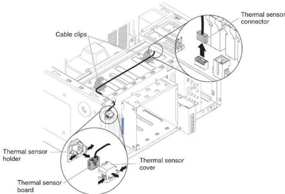
Figure204. Thermalsensorboardremovalfor4Uservermodelwithnon-hot-swappower supplies
- If you are instructed to return the thermals solution fankit, follow wall packaging instructions, and use an y packaging materials for shipping that a resupplied to you.
Toremovetheoperatingtemperatureenhancementkitonthe5Uservermodel withhot-swappowersupplies,completethefollowingsteps.For4Uservermodels withnon-hot-swappowersupplies,pleaseseetheabovesub-section.
- Readthesafetyinformationin"Safety"onpageviiand"Installation guidelines"onpage35.
- Turnoff the server and all attached devices; then, disconnect all power cords and external cables.
- Unlockandremovethesidecover(see"Removingthesidecover"onpage38).
- Removethelowerbezel(see"Removingthelowerbezel"onpage42).
- Removetheupperbezel(see"Removingtheupperbezel" onpage43).
- Carefullyturntheserveronitssidesothatitislyingflat,withthecoverfacing up.
Attention: Donotallowtheservertofallover.
- Disconnect the thermalsensor connector from the system board and open the cable clips.

Figure205. Thermalsensorconnectorremovalfromsystemboardfor5Uservermodelwith hot-swappowersupplies
- Removethethermalsensorboardbypullingapartthesecuringclipsofthe thermalsensorboardholder.

Figure206. Thermalsensorboardremovalfor5Uservermodelwithhot-swappowersupplies
- If you are instructed to return the thermals solution fankit, follow wall packaging instructions, and use an y packaging materials for shipping that a resupplied to you.
Replacingtheoperatingtemperatureenhancementkit
Usethisinformationtoreplacetheoperatingtemperatureenhancementkit
Attention: To ensure proper cooling and airflow, donot operate the server for more than 30 minutes with the side cover removed.
Toinstalltheoperatingtemperatureenhancementkitonthe4Uservermodelwith non-hot-swappowersupplies,completethefollowingsteps.For5Uservermodels withhot-swappowersupplies,pleaseseethenextsub-section.
-
Readthesafetyinformationin"Safety"onpageviiand"Installation guidelines"onpage35.
-
Insertthethermalsensorboardintothethermalsensorholder.Makesurethe cablinggoesthroughtheholeasshownintheillustrationandconnectthe thermalsensorconnectortothesystemboard.Remembertoclosethecable clipstosecurethecable.
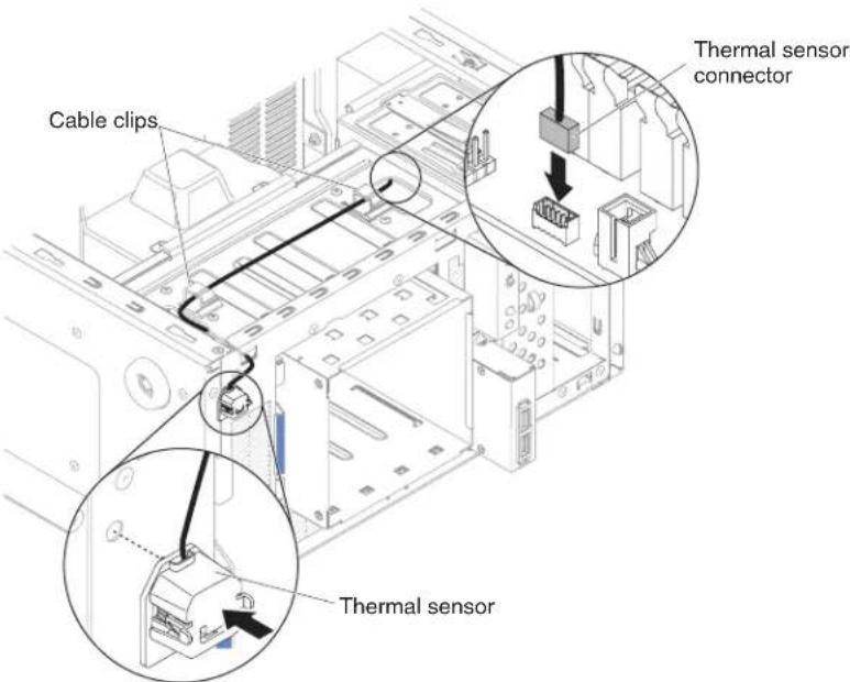
Figure207. Thermalsensorboardinstallationfor4Uservermodelwithnon-hot-swappower supplies
- Installthesidecover(see"Replacingthesidecover"onpage182).
- Standtheserverbackupinitsverticalposition.
- Installthebezel(see"Replacingthebezel"onpage188).
- Reconnecttheexternalcablesandpowercords;then,turnontheattached devicesandturnontheserver.
Toinstalltheoperatingtemperatureenhancementkitonthe5Usermodelwith hot-swappowersupplies,completethefollowingsteps.For4Usermodelswith non-hot-swappowersupplies,pleaseseetheabovesub-section.
-
Readthesafetyinformationin"Safety"onpageviiand"Installation guidelines"onpage35.
-
Insertthethermalsensorboardintothethermalsensorholderandtheninstall theholderontothechassis.Makesurethecablinggoesthroughtherespective
holesasshownintheillustration.
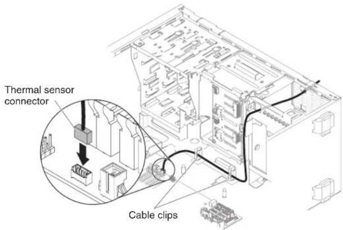
Figure208. Thermalsensorboardinstallationfor5Uservermodelwithhot-swappower supplies
- Connectthethermalsensorconnectortothesystemboard.Remembertoclose thecableclipstosecurethecable.

Figure209. Installing thermalsensorconnectortosystemboard for 5Usermodel with non-hot-swappowersupplies
- Standtheserverbackupinitsverticalposition.
- Installtheupperbezel(see"Replacingtheupperbezel"onpage192).
- Installthelowerbezel(see"Replacingthelowerbezel"onpage190).
- Installandlockthesidecover(see "Replacingthesidecover" on page 182).
- Reconnecttheexternalcablesandpowercords;then,turnontheattached devicesandturnontheserver.
RemovingandreplacingTier2CRUs
YoumayinstallaTier2CRUyourselforrequestIBMtoinstallit,atnoadditional charge,underthetypeofwarrantyservicethatisdesignatedforyourserver.
Theillustrationsinthisdocumentmightdifferslightlyfromyourhardware.
Removingthehot-swappowersupplycage
Thisprocedureappliesonlytothe5Uservermodelwithhot-swappowersupplies.
Toremovethehot-swappower-supplycagefromthe5Uservermodelwith hot-swappowersupplies,completethefollowingsteps.
-
Readthesafetyinformationin"Safety"onpageviand"Installation guidelines"onpage35.
-
Turnoff the server and all attached devices; then, disconnect all power cords and external cables.
-
Unlockandremovethesidecover(see"Removingthesidecover"onpage38).
-
Removethehot-swappowersupplies(see"Removingthehot-swappower supply"onpage263).
-
Carefully turn the server on it sides so that it is lying flat, with the system board facing up.
Attention: Donotallowtheservertofallover.
- Disconnect the cables from the power-supply cageto the system board and all internal components. Rotatethe hard disk drive cage out of the chassis to remove the power cable from the back plane.

Figure210.Powercableremovalfrombackplanefor5Uservermodelwithhot-swappower supplies(1)

Figure211. Powercableremovalfrombackplanefor5Uservermodelwithhot-swappower supplies(2)
- Removethetwoscrewsthatsecurethepower-supplycagetothechassis;the twoscrewsarelocatedinthefrontofthehot-swappowersupplycage.

Figure212. Hot-swappowersupplycagescrewremovalfor5Uservermodelwithhot-swap powersupplies
- Removetheotherfourscrewsthatalsosecurethepower-supplycagetothe chassis;then,slidethecagetowardthefrontoftheservertodisengagethe retainingclipsfromthetopofthechassisandliftthecageoutofthechassis.
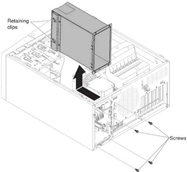
Figure213. Hot-swappowersupplycageandscrewremovalfor5Uservermodelwith hot-swappowersupplies
- If you are instructed to return the power-supply cage, follow all packaging instructions, and use an y packaging materials for shipping that a resupplied to you.
Replacingthehot-swappowersupplycage
Thisprocedureappliesonlytothe5Uservermodelwithhot-swappowersupplies.
Toinstallthehot-swappowersupplycageinthe5Uservermodelwithhot-swap powersupplies,completethefollowingsteps.
-
Readthesafetyinformationin"Safety"onpageviiand"Installation guidelines"onpage35.
-
Placethepower-supplycageintothechassisandslideittowardtherearofthe serveruntiltheretainingclipsengagethetopofthechassis,theninstallthe fourscrewstosecurethepower-supplycagetothechassis.
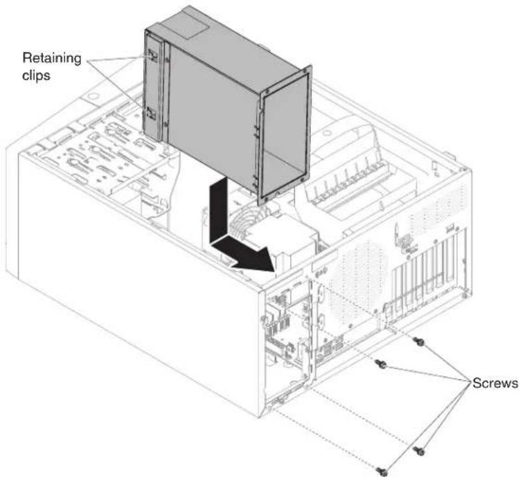
Figure214. Hot-swappowersupplycageandscrewinstallationfor5Uservermodelwith hot-swappowersupplies
- Installtheothertwoscrewstofurthersecurethepower-supplycagetothe chassis,whichislocatedonthefrontofthepower-supplycage.

Figure215.Hot-swappowersupplycagescrewinstallationfor5Uservermodelwith hot-swappowersupplies
- Connectthecablesfromthepower-supplycagetothesystemboardandall internalcomponents(see"System-boardinternalconnectors"onpage30forthe locationsoftheinternalconnectors).Rotatetheharddiskdrivecageoutofthe chassistoinsertthepowercabletothebackplane.
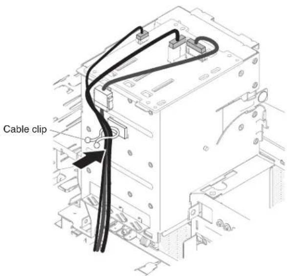
Figure216. Powercableinsertiontothebackplanefor5Uservermodelwithhot-swappower supplies(1)
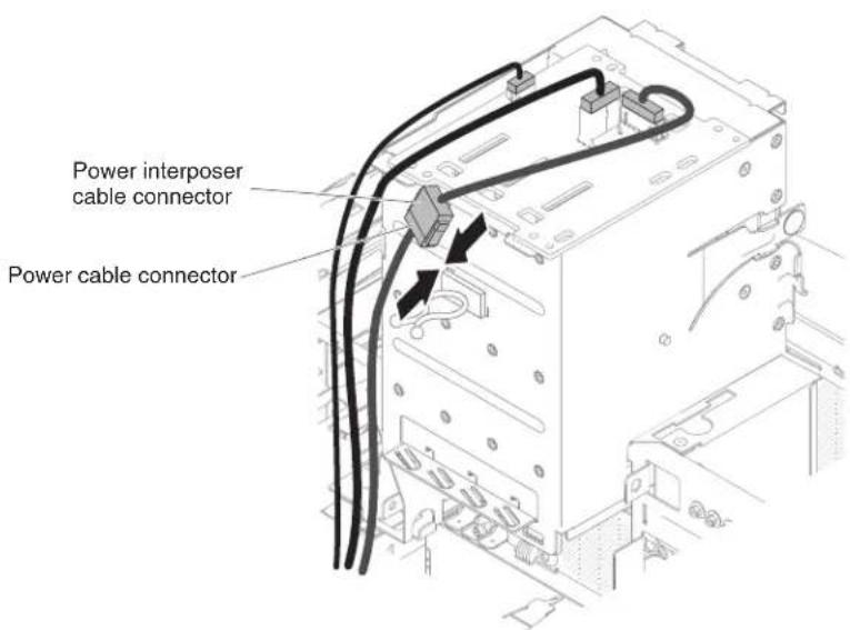
Figure217. Powercableinsertion to the backplane for 5 User vermodel with hot-swappower supplies(2)

Figure218. Powercableinsertiontothebackplanefor5Uservermodelwithhot-swappower supplies(3)
- Standtheserverbackupinitsverticalposition.
- Reinstallthehot-swappowersupplies(see"Repacingthehot-swappower supply"onpage264).
- Installandlockthesidecover(see"Replacingthesidecover" onpage182).
- Reconnecttheexternalcablesandpowercords;then,turnontheattached devicesandturnontheserver.
Removingthemicroprocessorandheatsink
Usethisinformationtoremovethemicroprocessorandheatsink
Toremovethemicroprocessorandheatsinkonthe4Uservermodelwith non-hot-swappowersupplies,completethefollowingsteps.For5Uservermodels withhot-swappowersupplies,pleaseseethenextsub-section.
- Readthesafetyinformationin"Safety"onpageviiand"Installation guidelines"onpage35.
- Turnoff the server and all attached devices; then, disconnect all power cords and external cables.
- Carefullyturntheserveronitssidesothatitislyingflat,withthecover facingup.
Attention: Donotallowtheservertofallover.
- Removethesidecover(see"Removingthesidecover"onpage38).
- Removetheairbaffle(see"Removingtheairbaffle" on page39).
- Removetheheatsinkfromthemicroprocessor:
CAUTION:
Theheatsinkmaybecomeveryhotduringnormaloperation.Allowtime fortheheatsinktocooldownbeforeyoutouchit.
a. Loosenthescrewsandalternateamongthescrewsuntiltheybreakthe sealwiththemicroprocessor.
b. Pressfirmlyonthecaptivescrewsandloosenthemwithascrewdriver.
c. Useyourfingerstogentlypulltheheatsinkfromthemicroprocessor.
Important: Becareful when you handle the microprocessor and heatsink. If the microprocessor and heatsink will be reused, donotcontaminatethe thermal material between them.

Figure219.Heatsinkremovalfor4Uservermodelwithnon-hot-swappowersupplies
Attention: Themicroprocessorretentionlatchisspring-loadedwhenthe microprocessorisinplace.Releasingthelatchtooquicklyorallowingitto springupwardcandamagethemicroprocessorandsurroundingcomponents.
- Releasethemicroprocessorretentionlatchbypassingdownontheend, movingittotheside, and slowly releasing ittotheopen(up)position.

Figure220. Microprocessorsocketleversandretainerdisengagementfor4Uservermodel withnon-hot-swappowersupplies
-
Openthemicroprocessorbracketframebyliftingupthetabonthetopedge.
-
Carefully lift them microprocessor straightup and out of the socket, and place it on a static-protectives surface.
-
If you are instructed to return them microprocessor and heatsink, follow all packaging instructions, and use an typackaging materials for shipping that are supplied to you.
Toremovethemicroprocessorandheatsinkonthe5Uservermodelwith hot-swappowersupplies,completethefollowingsteps.For4Uservermodelswith non-hot-swappowersupplies,pleaseseetheabovesub-section.
-
Read the safety information in "Safety" on page vi and "Installation guidelines" on page 35.
-
Turnoff the server and all attached devices; then, disconnect all power cords and external cables.
-
Unlockandremovethesidecover(see"Removingthesidecover" on page 38).
-
Carefullyturntheserveronitssidesothatitislyingflat, with the system boardfacingup.
Attention: Donotallowtheservertofallover.
-
Rotatetherearadapter-retentionbrackettotheopen(unlocked)position.
-
Removetheatsinkfromthemicroprocessor:
CAUTION: Theheatsinkmaybecomeveryhotduringnormaloperation.Allowtime fortheheatsinktocooldownbeforeyoutouchit.
a. Loosenthescrewsandalternateamongthescrewsuntiltheybreakthe sealwiththemicroprocessor.
b. Pressfirmlyonthecaptivescrewsandloosenthemwithascrewdriver.
c. Useyourfingerstogentlypulltheheatsinkfromthemicroprocessor.
Important: Becareful when you handle them microprocessor and heatsink. If them microprocessor and heatsink will be reused, donotcontaminate the thermal material between them.
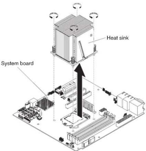
Figure221.Heatsinkremovalfor5Uservermodelwithhot-swappowersupplies
Attention: Themicroprocessorretentionlatchisspring-loaded when the microprocessorisinplace. Releasingthelatchtooquicklyorallowingitto springupwardcandamagethemicroprocessorandsurroundingcomponents.
- Releasethemicroprocessorretentionlatchbypassingdownontheend, movingittotheside, and slowly releasing ittotheopen(up)position.

Figure222. Microprocessorsocketleversandretainerdisengagementfor5Uservermodel withhot-swappowersupplies
- Openthemicroprocessorbracketframebyliftingupthetabonthetopedge.
- Carefully lift them microprocessor straightup and out of the socket, and place it on a static-protectives surface.
- If you are instructed to return them microprocessor and heatsink, follow all packaging instructions, and use an typackaging materials for shipping that are supplied to you.
Replacingthemicroprocessorandheatsink
Usethisinformationoreplacethemicroprocessorandheatsink
Toinstallthemicroprocessorandheatsinkonthe4Uservermodelwith non-hot-swappowersupplies,completethefollowingsteps.For5Uservermodels withhot-swappowersupplies,pleaseseethenextsub-section.
- Readthesafetyinformationin"Safety"onpageviiand"Installation guidelines"onpage35.
- Touchthestatic-protectivepackagethatcontainsthemicroprocessortoany unpaintedmetalsurfaceontheserver.Then,removethemicroprocessorfrom thepackage.
- Removetheprotectivecover, tape, or labelfrom the surface of the microprocessor socket, if any is present.
- Rotatethereleaseleveronthemicroprocessorsockettothefullyopen position.
Attention: Makesure that there lease leveronthemicroprocessorsocket is in the fully open position before you insert them microprocessor in the socket. Failure todos might result in permanent damage to them microprocessor, microprocessor socket, and system board.
- Carefullygraspthemicroprocessorandplacethemicroprocessorintothe microprocessorsocket.
Note: Tomaintaincorrectorientationbetweenthemicroprocessorandthe microprocessorsocketduringinstallation,observethefollowinginformation:
- Themicroprocessorhastwonotchesthatarekeyedtotwotabsonthesides ofthesocket.
- A triangle-shaped indicator on one corner of the microprocessor point stoa 45-degree angle on the system board.
-
Donotuseexcessiveforcewhenyoupressthemicroprocessorintothe socket.
-
Closethemicroprocessorbracketframe;then,closethemicroprocessor retentionlatchandlockitsecurelyinplace.

Figure223. Microprocessorsocketleversandretainerengagementfor4Uservermodelwith non-hot-swappowersupplies
7. Installtheheatsink:
Attention: Donottouchthethermalmaterialonthebottomoftheheatsink. Touchingthethermalmaterialwillcontaminateit. If thethermalmaterialon themicroprocessororheatsinkbecomescontaminated, contact your service technician.
a. Alignthescrewholesontheheatsinkwiththeholesonthesystemboard.
b. Tightenthescrewswithascrewdriver,alternatingamongthescrewsuntil theyaretight.Ifpossible,eachscrewshouldberotatedtwofullrotations atatime.Repeatuntilthescrewsaretight.Donotovertightenthescrews byusingexcessiveforce.

Figure224.Heatsinkinstallationfor4Uservermodelwithnon-hot-swappowersupplies
- Reconnectanycable that you disconnected during theremoval of the old microprocessor.
- SecuretheSATAsignalcableswiththeretention-clips.
- Installtheairbaffle(see"Replacingtheairbaffle"onpage185).
- Installthesidecover(see "Replacingthesidecover" on page 182).
- Standtheserverbackupinitsverticalposition.
- Installthebezel(see"Replacingthebezel"onpage188).
- Reconnecttheexternalcablesandpowercords;then,turnontheattached devicesandturnontheserver.
Toinstall themicroprocessor and heatsinkon the 5User vermodel with hot-swap powersupplies, complet the following steps. For 4User vermodel with non-hot-swappowersupplies, please seethe abovesub-section.
- Readthesafetyinformationin"Safety"onpageviiand"Installation guidelines"onpage35.
- Touchthestatic-protectivepackagethatcontainsthemicroprocessortoany unpaintedmetalsurfaceontheserver.Then,removethemicroprocessorfrom thepackage.
- Removetheprotectivecover, tape, orlabelfromthesurfaceofthe microprocessorsocket, ifanyispresent.
- Rotatethereleaseleveronthemicroprocessorsockettothefullyopen position.
Attention: Makesurethatthereleaseleveronthemicroprocessorsocketis inthefullyopenpositionbeforeyouinsertthemicroprocessorinthesocket. Failuretodosomightresultinpermanentdamagetothemicroprocessor, microprocessorsocket,andsystemboard.
- Carefullygraspthemicroprocessorandplacethemicroprocessorintothe microprocessorsocket.
Note: Tomaintaincorrectorientationbetweenthemicroprocessorandthe microprocessorsocketduringinstallation,observethefollowinginformation:
• Themicroprocessorhastwonotchesthatarekeyedtotwotabsonthesides ofthesocket.
- A triangle-shaped indicator on one corner of the microprocessor point stoa 45-degree angle on the system board.
- Donotuseexcessiveforcewhenyoupressthemicroprocessorintothe socket.
- Closethemicroprocessorbracketframe; then, closethemicroprocessor retentionlatchandlockitsecurelyinplace.
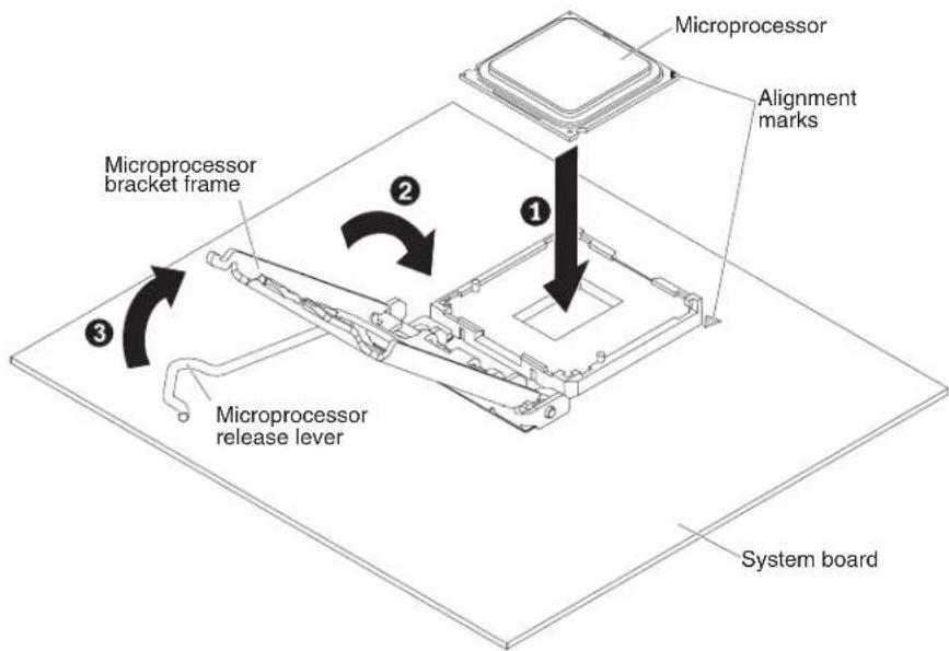
Figure225. Microprocessorsocketleversandretainerengagementfor5Uservermodelwith hot-swappowersupplies
7. Installtheheatsink:
Attention: Donottouchthethermalmaterialonthebottomoftheheatsink. Touchingthethermalmaterialwillcontaminateit. If the thermal material on themicroprocessororheatsinkbecomescontaminated, contact your service technician.
a. Alignthescrewholesontheheatsinkwiththeholesonthesystemboard.
b. Tightenthescrewswithascrewdriver,alternatingamongthescrewsuntil theyaretight.Ifpossible,eachscrewshouldberotatedtwofullrotations atatime.Repeatuntilthescrewsaretight.Donotovertightenthescrews byusingexcessiveforce.

Figure226.Heatsinkinstallationfor5Uservermodelwithhot-swappowersupplies
- Reconnectanycable that you disconnected during theremoval of the old microprocessor.
- Rotatetherearadapter-retentionbrackettotheclosed(locked)position.
- Standtheserverbackupinitsverticalposition.
- Installandlockthesidecover(see "Replacingthesidecover" on page 182).
- Reconnecttheexternalcablesandpowercords;then,turnontheattached devicesandturnontheserver.
Thermalgrease:
Thethermalgreasemustbereplacedwhenevertheheatsinkhasbeenremoved fromthetopofthemicroprocessorandisgoingtobereusedorwhendebrisis foundinthegrease. Usethisinformationoreplacedamagedorcontaminated thermalgreaseonthemicroprocessorandheatsink.
When you are installing the heatsinkonthesamemicroprocessorthatiswas removed from, makesurethatthefollowingrequirementsaremet:
• Thethermalgreaseontheheatsinkandmicroprocessorisnotcontaminated.
• Additional thermal grease is not added to the existing thermal grease on the heatsink and microprocessor.
Notes:
- Readthesafetyinformationin"Safety"onpagevii.
- Readthe"Installationguidelines" onpage35.
- Read "Handlingstatic-sensitivedevices" on page 37.
Toreplacedamagedorcontaminatedthermalgreaseonthemicroprocessorand heatsink,completethefollowingsteps:
- Placetheheatsinkonacleanworksurface.
-
Removethecleaningpadfromitspackageandunfolditcompletely.
-
Usethecleaningpadtowipethethermalgreasefromthebottomoftheheat sink.
Note: Makesurethatallofthermalgreaseisremoved.
-
Useacleanareaofthecleaningpadtowipethethermalgreasefromthe microprocessor;then,disposeofthecleaningpadafterallofthethermalgrease isremoved.
-
Use the thermal-greasesyringetoplace9uniformlyspaceddotsof0.02mL eachonthetopofthemicroprocessor. The outermostdotsmustbewithin approximately 5mmoftheedgeofthemicroprocessor; thisistoensure uniformdistributionofthegrease.

Figure227. Thermalgreasedistribution
Note: If the grease is properly applied, approximately half of the greas will remain in the syringe.
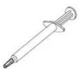
Figure228.Syringe
- Installtheheatsinkontothemicroprocessorasdescribedin"Replacing the microprocessorandheatsink"onpage304.
Removingthesystemboard
Usethisinformationtoremovethesystemboard.
Beforeyouremovethesystemboardfromtheserver,takethefollowingstepsto savedata,firmware,andconfigurationdata:
- Recordallsystemconfigurationinformation,suchasIMMIPaddresses,vital productdata,andthemachinetype,modelnumber,serialnumber,Universally UniqueIdentifier,andassettagoftheserver.
- UsingtheAdvancedSettingsUtility(ASU),savethesystemconfigurationto externalmedia.
•Savethesystem-eventlogtoexternalmedia.
Note: When you're placethesystemboard, you must either update the server with the latest firmware or restore the pre-existing firmware that the customer provides on a CD or DVD image. Makes sure that you have the latest firmware or a copy of the pre-existing firmware before you proceed.
Toremovethesystemboardonthe4Uservermodelwithnon-hot-swappower supplies,completethefollowingsteps.For5Uservermodelswithhot-swappower supplies,pleaseseethenextsub-section.
-
Readthesafetyinformationin"Safety"onpageviiand"Installation guidelines"onpage35.
-
Turnoff the server and all peripheral devices; then, disconnect the power cords and all external cables.
-
Carefullyturntheserveronitssidesothatitislyingflat, with thecover facing up.
Attention: Donotallowtheserverterofallover.
-
Removethesidecover(see "Removingthesidecover" on page 38).
-
Removetheairbaffle(see "Removingtheairbaffle" on page 39).
-
Removethemicroprocessorandheatsink(see"Removingthemicroprocessor andheatsink"onpage300).
Attention: Removethesocketcoversfromthemicroprocessorsocketsonthe newsystemboardandplacethemonthemicroprocessorsocketsofthe systemboardyouareremoving.
- Pulltheharddiskdrivecagehalfoutofthechassis.

natural_image
Technical line drawing of an internal computer tower with visible internal components and ventilation ducts (no text or labels)Figure229. Pullingharddiskdrivecagehalfoutofchassisfor4Uservermodelwith non-hot-swappowersupplies
- Disengagethecablesfromanyretention-clips.
- Notewhereeachcableisconnected;then,disconnectallcablesfromthe systemboard.
Attention: Disengagealllatches, releasetabsorlocksoncableconnectors when you disconnectallcablesfromthesystemboard. Failingtoreleasethem beforeremovingthecableswilldamagethecablesocketsonthesystemboard. Thecablesocketsonthesystemboardarefragile. Anydamagetothecable socketsmayrequirereplacingthesystemboard.
-
Remove any of the following components (in addition to other that might not be listed) that are installed on the system board and put them in asafe, static-protective place:
-
Adapters(see"Removinganadapter"onpage266).
•DIMMs(see"Replacingamemorymodule"onpage274). - Battery(see"Removingthesystembattery"onpage279).
-
USBembeddedhypervisorflashdevice(see"RemovingtheUSBembeddedhypervisorflashdevice"onpage227).
-
Removethesevenscrewsthatsecurethesystemboardtothechassis.

Figure230. Systemboardscrewremovalfor4Uservermodelwithnon-hot-swappower supplies
- Slightly lift the system board at the sidesidethatis near the hard disk drive cage to create a small angle of elevation between the system board and chassis.

Figure231. Slightlyliftingsystemboardfor4Uservermodelwithnon-hot-swappower supplies
- Gentlypushtheexternalinput/outputconnectorsoutoftheirrespectiveholes inthechassis.
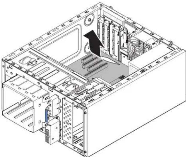
natural_image
Isometric technical diagram of a computer tower case with visible internal components and a black arrow indicating a specific area (no text or labels present)Figure232. Pushingexternalinput/outputconnectorsoutofchassisfor4Uservermodelwith non-hot-swappowersupplies
- Graspthesystemboardbytheedges;then,carefullyliftupthesystemboard andremoveitfromthechassis,beingcarefulnottodamageanysurrounding components.
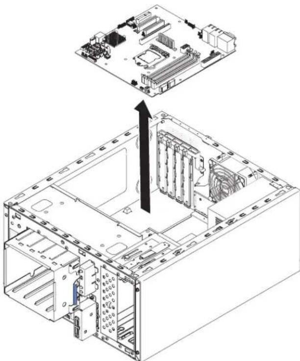
natural_image
Technical line drawing of a computer motherboard showing CPU socket, drive bays, and internal components (no text or labels)Figure233.Systemboardremovalfor4Uservermodelwithnon-hot-swappowersupplies
- If you are instructed to return the system board, follow all packaging instructions, and use an app packaging materials for shipping that a resupplied to you.
Attention: Makesuretoplacethesocketcoversforthemicroprocessor socketsonthesystemboardbeforereturningthesystemboard.
Toremovethesystemboardonthe5Uservermodelwithhot-swappower supplies,completethefollowingsteps.For4Uservermodelswithnon-hot-swap powersupplies,pleaseseetheabovesub-section.
- Readthesafetyinformationin"Safety"onpageviiand"Installation guidelines"onpage35.
- Turnoff the server and all attached devices; then, disconnect all power cords and external cables.
- Unlockandremovethesidecover(see"Removingthesidecover" on page 38).
- Carefullyturntheserveronitssidesothatitislyingflat,withthesystem boardfacingup.
Attention: Donotallowtheservertofallover.
-
Rotatetherearadapter-retentionbrackettotheopen(unlocked)position.
-
Removetheharddiskdrivefanduct(see"Removingtheharddiskdrivefanduct"onpage222).
-
Removethemicroprocessorandheatsink(see"Removingthemicroprocessor andheatsink"onpage300).
Attention: Removethesocketcoversfromthemicroprocessorsocketsonthe newsystemboardandplacethemonthemicroprocessorsocketsofthe systemboardyouareremoving.
-
Disengagethecablesfromanyretention-clips.
-
Notewhereeachcableisconnected;then,disconnectallcablesfromthe systemboard.
Attention: Disengage all latches, releasetabsorlocksoncableconnectors when you disconnect all cables from the system board. Failing to releasethem before removing the cables will damage the cables oset on the system board. The cables oset on the system board are fragile. Any damagetothecable sockets may require replacing the system board.
- Removeanyofthefollowingcomponents(inadditiontoothersthatmightnot belisted)thatareinstalledonthesystemboardandputtheminasafe, static-protectiveplace:
- Adapters(see"Removinganadapter" on page266).
•DIMMs(see"Replacingamemorymodule"onpage274).
- Battery(see"Removingthesystembattery" onpage279).
- USBembeddedhypervisorflashdevice(see"RemovingtheUSBembeddedhypervisorflashdevice"onpage227).
- Removethesevenscrewsthatsecurethesystemboardtothechassis.
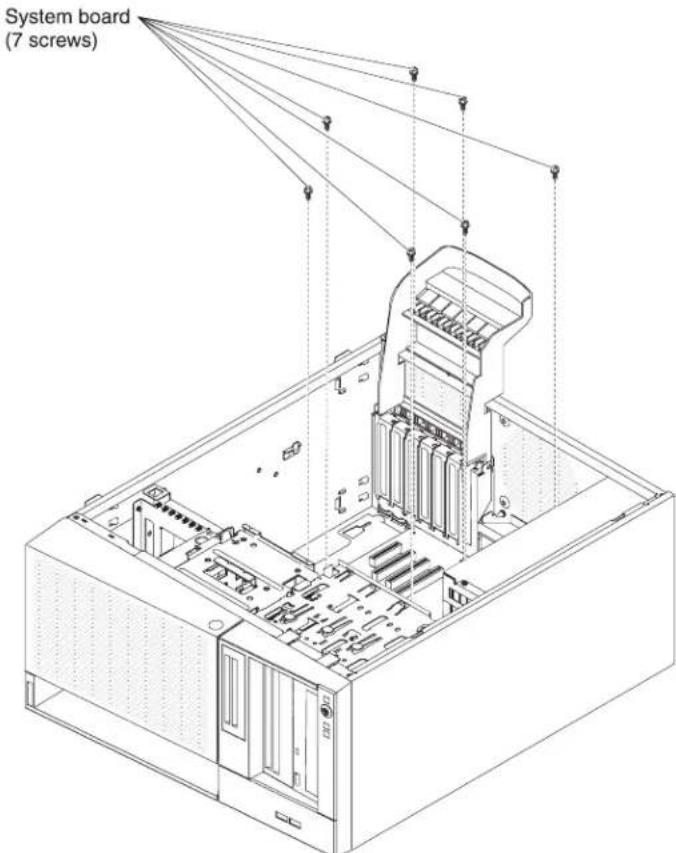
Figure234. Systemboardscrewremovalfor5Uservermodelwithhot-swappowersupplies
- Slightly lift the system board at the sidesidethatis near the hard disk drive cage to create a small angle of elevation between the system board and chassis.

Figure235.Slightlyliftingsystemboardfor5Uservermodelwithhot-swappowersupplies
- Gentlypushtheexternalinput/outputconnectorsoutoftheirrespectiveholes inthechassis.

natural_image
Isometric line drawing of a computer tower internal structure showing internal components like CPU, RAM slots, and drive bays (no text or labels)Figure236. Pushingexternalinput/outputconnectorsoutofchassisfor5Uservermodelwith hot-swappowersupplies
- Graspthesystemboardbytheedges;then,carefullyliftupthesystemboard andremoveitfromthechassis,beingcarefulnottodamageanysurrounding components.

natural_image
Isometric diagram of a computer motherboard showing CPU socket, drive bays, and internal components (no text or labels)Figure237. Systemboardremovalfor5Uservermodelwithhot-swappowersupplies
- If you are instructed to return the system board, follow all packaging instructions, and use any packaging materials for shipping that aresupplied to you.
Attention: Makesuretoplacethesocketcoversforthemicroprocessor socketsonthesystemboardbeforereturningthesystemboard.
Replacingthesystemboard
Usethisinformationoreplacethesystemboard.
Note:
-
When you are assemble the components in the server, besuretoroute all cables carefully so that they are not exposed to excessive pressure.
-
Whenyoureplacethesystemboard,youmusteitherupdatetheserverwith thelatestfirmwareorrestorethepre-existingfirmwarethatthecustomer providesonadisketteorCDimage.Thevitalproductdata(VPD)mustalsobe updated.Makesurethatyouhavethelatestfirmwareoracopyofthe pre-existingfirmwarebeforeyouproceed.See"Updatingthefirmware"on page93and(see"UpdatingtheDMI/SMBIOSdata"onpage116)formore information.
Attention: Installing the wrong firmware or device-driver updatemight cause the server to malfunction. Before you install a firmware or device-driver update, read any read me and change history file that are provided with the downloaded update. These files contain important information about the update and the procedure for installing the update, including anyspecial procedure for updating from an early firmware or device-driverversion to the latest version.
- ReactivateanyFeaturesonDemandfeatures.Instructionsforautomatingthe activationoffeaturesandinstallingactivationkeysisintheIBMSystemx FeaturesonDemandUser'sGuide.Todownloadthedocument,goto /http://www.ibm.com/systems/x/fod/,login,andclickHelp.
Important: Some clusters solutions requires specific code levels or coordinated code updates. If the device is part of clusters solution, verify that the latest level of code is supported for the clusters solution before you update the decode
Toinstallthesystemboardonthe4Uservermodelwithnon-hot-swappower supplies,completethefollowingsteps.For5Uservermodelswithhot-swappower supplies,pleaseseethenextsub-section.
-
Readthesafetyinformationin"Safety"onpageviiand"Installation guidelines"onpage35.
-
Pulltheharddiskdrivecagehalfoutofthechassis.

natural_image
Technical line drawing of an internal computer tower with visible drive bays and cable (no text or labels)Figure238. Pullingharddiskdrivecagehalfoutofchassisfor4Uservermodelwith non-hot-swappowersupplies
-
Touchthestatic-protectivepackagethatcontainsthesystemboardtoany unpaintedmetalsurfaceontheserver.Then,removethesystemboardfrom thepackage.
-
Lowerthesystemboardintothechassis.Payattentiontothepositionsofthestandoffsastheywillbeusedlater.

Figure239. Systemboard installation for 4User vermodel with non-hot-swappowersupplies
- Gentlypushthesystemboardbythesidenaresttothefancagetoinserthe externalinput/outputconnectorsintotheirrespectiveholesinthechassis.

natural_image
Technical line drawing of a computer tower case with internal components and an arrow indicating a specific area (no text or symbols present)Figure240.Pushingexternalinput/outputconnectorsintochassisfor4Uservermodelwith non-hot-swappowersupplies
Attention: When inserting the system board external input/output connectors into their respective holes in the chassis, makes sure the EMC springs are not inserted into the holes. Inserting the EMC springs into the holes in the chassis could damage the EMC springs.
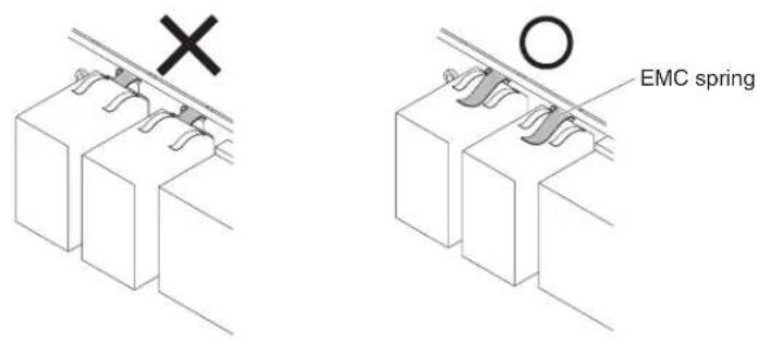
Figure241.HowtocorrectlyinsertEMCsprings
- Aligntheholes(sevenintotal)onthesystemboardwiththerespective standoffsonthechassis.

Figure242. Systemboardalignmentwithrespectivestandoffsonchassisfor4Userver modelwithnon-hot-swappowersupplies
- Install these seven screws that secure the system board to the chassis.
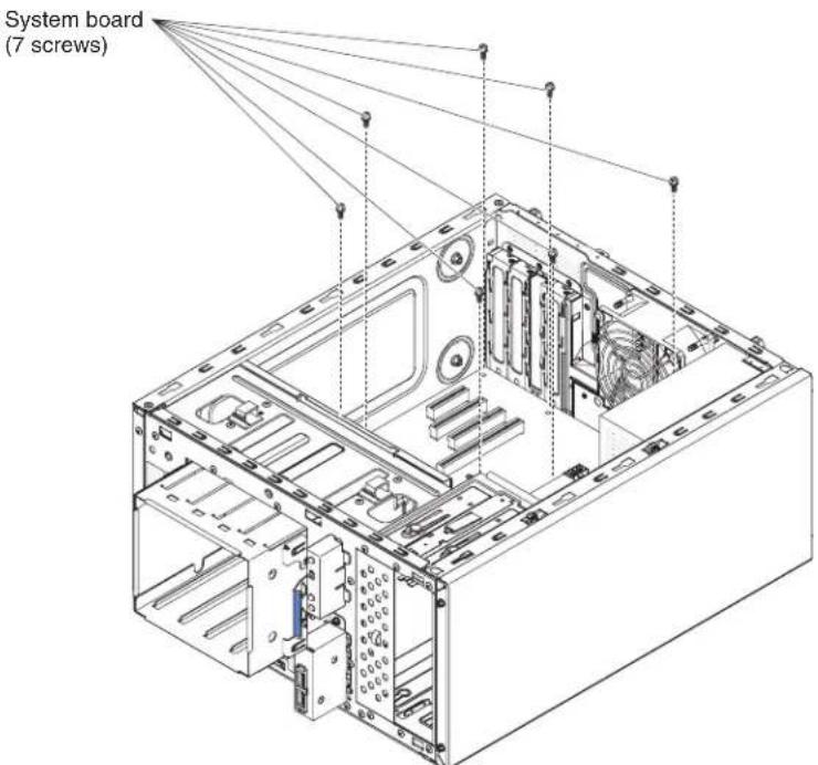
Figure243. Systemboardscrewinstallationfor4Uservermodelwithnon-hot-swappower supplies
-
Installanyofthefollowingcomponentsthatyouremovedfromthesystem board:
-
Battery(see"Replacingthesystembattery"onpage281).
•DIMMs(see"Replacingamemorymodule"onpage274). - Microprocessorandheatsink(see "Replacingthemicroprocessorandheat sink" onpage304).
-Adapters(see"Replacinganadapter"onpage269). -
USBembeddedhypervisorflashdevice(see"ReplacingtheUSBembeddedhypervisorflashdevice"onpage230).
-
Reconnectanycabletothesystemboardthatyoudisconnectedduring removal(see "System-boardinternalconnectors" onpage30).
-
Securethecableswiththeretention-clips.
- Presstheharddiskdrivecageinuntilthereleaselatchesclickintoplace.
- Installtheairbaffle(see"Replacingtheairbaffle"onpage185).
- Installthesidecover(see"Replacingthesidecover"onpage182).
- Standtheserverbackupinitsverticalposition.
- Installbezel(see"Replacingthebezel"onpage188).
- Reconnecttheexternalcablesandpowercords;then,turnontheattached devicesandturnontheserver.
Important: Perform the following updates:
- EitherupdatetheserverwiththelatestRAIDfirmwareorrestorethe pre-existingfirmwarefromadisketteorCDimage.
- UpdatetheUUID(see"UpdatingtheUniversalUniqueIdentifier(UUID)" onpage113)
- Update the DMI/SMBIOS(see "Updating the DMI/SMBIOS data" on page 116).
•ReactivateanyFeaturesonDemandfeatures.
Toinstallthesystemboardonthe5Uservermodelwithhot-swappowersupplies, completethefollowingsteps.For4Uservermodelswithnon-hot-swappower supplies,pleaseseetheabovesub-section.
- Readthesafetyinformationin"Safety"onpageviiand"Installation guidelines"onpage35.
- Touchthestatic-protectivepackagethatcontainsthesystemboardtoany unpaintedmetalsurfaceontheserver.Then,removethesystemboardfrom thepackage.
- Lowerthesystemboardintothechassis.Payattentiontothepositionsofthestandoffsastheywillbeusedlater.
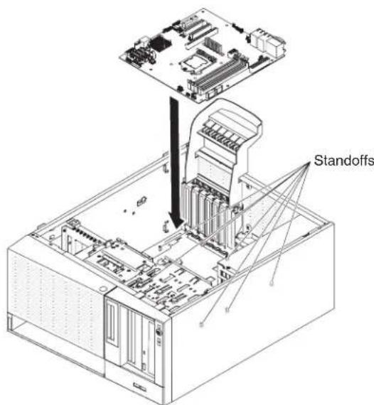
Figure244. Systemboard installation for 5User vermodel with hot-swappowersupplies
- Gentlypushthesystemboardbythesidenearesttothefancagetoinserthe externalinput/outputconnectorsintotheirrespectiveholesinthechassis.

natural_image
Isometric line drawing of a computer tower internal structure showing internal components like CPU socket and drive bays (no text or labels)Figure245.Pushingexternalinput/outputconnectorsintochassisfor5Uservermodelwith hot-swappowersupplies
Attention: When inserting the system board external input/output connectors into their respective holes in the chassis, makes sure the EMC springs are not inserted into the holes. Inserting the EMC springs into the holes in the chassis could damage the EMC springs.

natural_image
Diagram of two rectangular blocks mounted on a wall with a black X mark above (no text or symbols)
Figure246.HowtocorrectlyinsertEMCsprings
- Aligntheholes(sevenintotal)onthesystemboardwiththerespective standoffsonthechassis.

Figure247. Systemboardalignmentwithrespectivestandoffsonchassisfor5Userver modelwithhot-swappowersupplies
- Installthesevenscrewsthatsecurethesystemboardtothechassis.
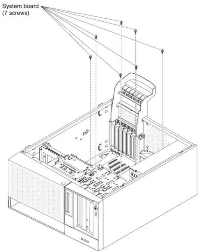
Figure248. Systemboardscrewinstallationfor5Uservermodelwithhot-swappower supplies
- Installanyofthefollowingcomponentsthatyouremovedfromthesystem board:
- Adapters(see "Replacinganadapter" on page 269).
- Battery(see"Replacingthesystembattery"onpage281).
•DIMMs(see "Replacingamemorymodule" onpage274).
- Microprocessorandheatsink(see"Replacingthemicroprocessorandheat sink"onpage304).
- USBembeddedhypervisorflashdevice(see"ReplacingtheUSBembeddedhypervisorflashdevice"onpage230).
- Reconnectanycablestothesystemboardthatyoudisconnectedduring removal(see"System-boardinternalconnectors"onpage30).
- Securethecables with theretention-clips.
- Installtheharddiskdrivefanduct(see"Replacingtheharddiskdrivefanduct"onpage225).
- Rotatetherearadapter-retentionbrackettotheclosed(locked)position.
- Standtheserverbackupinitsverticalposition.
- Installandlockthesidecover(see"Replacingthesidecover"onpage182).
- Reconnecttheexternalcablesandpowercords;then,turnontheattached devicesandturnontheserver.
Important: Perform the following updates:
- EitherupdatetheserverwiththelatestRAIDfirmwareorrestorethe pre-existingfirmwarefromadisketteorCDimage.
- UpdatetheUUID(see"UpdatingtheUniversalUniqueIdentifier(UUID)" onpage113)
- Update theDMI/SMBIOS(see "UpdatingtheDMI/SMBIOSdata" on page 116).
- ReactivateanyFeaturesonDemandfeatures.
AppendixA.IntegratedmanagementmoduleII(IMM2)error messages
WhenahardwareeventisdetectedbytheIMMontheserver,theIMMlogsthat eventinthesystem-eventlogintheserver.
Foreacheventcode, the following fields are displayed:
Eventidentifier
Ahexadecimalidentifierthatuniquelyidentifiesaneventorclassof events. In this documentation, the event identifiers are prefixed with 0x and followed by eight characters.
Eventdescription
Theloggedmessagestringthatappearsforanevent.Whentheevent stringisdisplayedinthesystem-eventlog,informationsuchasaspecific componentisdisplayed.Inthisdocumentation,thatadditionalinformation appearsasvariables,suchas[arg1]or[arg2].
Explanation
Additionalinformationtoexplainwhytheeventoccurred.
Severity
Anindicationofthelevelofconcernforthecondition.Inthesystem-event log,severityisabbreviatedtothefirstcharacter.Thefollowingseverities canbedisplayed.
Info: The event was recorded for audit purposes, usually auseraction or change of state that is normal behavior.
Warning:
The event is not as severe as an error, but if possible, the condition should be corrected before it becomes an error. It might also be a condition that requires additional monitoring or maintenance.
Error: The eventisafailure or critical condition that impairs service or an expected function.
AlertCategory
Similareventsaregroupedtogetherincategories.Thealertcategoryisin thefollowingformat:
severity-device
severityisoneofthefollowingseveritylevels:
•Critical:Akeycomponentintheserverisnolongerfunctioning.
- Warning: The event might progress to a critical level.
- System: The eventistheresultofasystemerrororaconfiguration change.
deviceisthespecificdeviceintheserverthatcausedtheeventtobe generated.
Serviceable
Whether user action is required to correct the problem.
CIMInformation
TheprefixofthemessageIDandthesequencenumberthatisusedbythe CIMmessageregistry.
SNMPTrapID
TheSNMPtrapIDthatisfoundintheSNMPalertmanagement informationbase(MIB).
AutomaticallycontactService
If this fieldissetto Yes, and you have enabled Electronic Service Agent (ESA), IBMSupport will be notified automatically if the event is generated.
While you wait for IBM Support to call, you can perform the recommended actions for the event.
Userresponse
Theactionsthatyoushouldperformtosolvetheevent.
Performthestepslistedinthissectionintheordershownuntilthe problemissolved. Afteryouperformalloftheactionsthataredescribed in thisfield, if you cannot solvetheproblem, contact IBMSupport.
Note: Thislistincludeserrorcodesandmessagesthatmightnotapplyto thismachinetypeandmodel.
The following isthelistofIMM2errormessages and suggested actionstocorrect the detected server problems. FormoreinformationaboutIMM2, seetheIntegrated
ManagementModuleIIUser'sGuideathttp://www-947.ibm.com/support/entry/
portal/docdisplay?Indocid=migr-5086346.
IMMEventsthatautomaticallynotifySupport
YoucanconfiguretheIntegratedManagementModuleII(IMM2)toautomatically notifySupport(alsoknownascallhome)ifcertaintypesoferrorsareencountered. Ifyouhaveconfiguredthisfunction,seethetableforalistofeventsthat automaticallynotifySupport.
Table40.EventsthatautomaticallynotifySupport
| EventIDMessageString | Automatically Notify Support | |
| 40000086-00000000TestCallHomeGeneratedbyuser[arg1].Yes | ||
| 40000087-00000000ManualCallHomebyuser[arg1]:[arg2].Yes | ||
| 80010202-0701ffffNumericsensor[NumericSensorElementName]goinglow(lowercritical)hasasserted.(CMOS Battery) | Yes | |
| 80010902-0701ffffNumericsensor[NumericSensorElementName]goinghigh(uppercritical)hasasserted. | Yes | |
| 806f0021-2201ffffFaultinslot[PhysicalConnectorSystemElementName]on system[ComputerSystemElementName].(NoOpROMSpace) | Yes | |
| 806f0021-2582ffffFaultinslot | [PhysicalConnectorSystemElementName]on system[ComputerSystemElementName].(AllPCIError/OneofPCIError) | Yes |
| 806f0021-3001ffffFaultinslot | [PhysicalConnectorSystemElementName]on system[ComputerSystemElementName].(PCI1) | Yes |
| 806f0021-3002ffffFaultinslot | [PhysicalConnectorSystemElementName]on system[ComputerSystemElementName].(PCI2) | Yes |
| 806f0021-3003ffffFaultinslot | [PhysicalConnectorSystemElementName]on system[ComputerSystemElementName].(PCI3) | Yes |
| 806f0021-3004ffffFaultinslot | [PhysicalConnectorSystemElementName]on system[ComputerSystemElementName].(PCI4) | Yes |
| 806f0108-0a01ffff[PowerSupply | ElementName]hasFailed.(PowerSupply1) | Yes |
| 806f0108-0a02ffff[PowerSupply | ElementName]hasFailed.(PowerSupply2) | Yes |
| 806f010c-2001ffffUncorrectable | errordetectedfor[PhysicalMemoryElementName]on Subsystem[MemoryElementName].(DIMM 1) | Yes |
| 806f010c-2002ffffUncorrectable | errordetectedfor[PhysicalMemoryElementName]on Subsystem[MemoryElementName].(DIMM 2) | Yes |
| 806f010c-2003ffffUncorrectable | errordetectedfor[PhysicalMemoryElementName]on Subsystem[MemoryElementName].(DIMM 3) | Yes |
| 806f010c-2004ffffUncorrectable | errordetectedfor[PhysicalMemoryElementName]on Subsystem[MemoryElementName].(DIMM 4) | Yes |
| 806f010c-2581ffffUncorrectable | errordetectedfor[PhysicalMemoryElementName]on Subsystem[MemoryElementName].(All DIMMS/OneoftheDIMMs) | Yes |
| 806f010d-0400ffffTheDrive[StorageVolumeElementName]hasbeendisabledduetoadetectedfault.(Drive0) | Yes | |
| 806f010d-0401ffffTheDrive[StorageVolumeElementName]hasbeendisabledduetoadetectedfault.(Drive1) | Yes | |
| 806f010d-0402ffffTheDrive[StorageVolumeElementName]hasbeendisabledduetoadetectedfault.(Drive2) | Yes | |
| 806f010d-0403ffffTheDrive[StorageVolumeElementName]hasbeendisabledduetoadetectedfault.(Drive3) | Yes | |
| 806f010d-0404ffffTheDrive[StorageVolumeElementName]hasbeendisabledduetoadetectedfault.(Drive4) | Yes | |
| 806f010d-0405ffffTheDrive[StorageVolumeElementName]hasbeendisabledduetoadetectedfault.(Drive5) | Yes | |
| 806f010d-0406ffffTheDrive[StorageVolumeElementName]hasbeendisabledduetoadetectedfault.(Drive6) | Yes | |
| 806f010d-0407ffffTheDrive[StorageVolumeElementName]hasbeendisabledduetoadetectedfault.(Drive7) | Yes | |
| 806f0207-0301ffff[ProcessorElementName]hasFailedwithFRB1/BISTcondition.(CPU1) | Yes | |
| 806f020d-0400ffffFailurePredictedondrive[StorageVolumeElementName]forarray[ComputerSystemElementName].(Drive0) | Yes | |
| 806f020d-0401ffffFailurePredictedondrive[StorageVolumeElementName]forarray[ComputerSystemElementName].(Drive1) | Yes | |
| 806f020d-0402ffffFailurePredictedondrive[StorageVolumeElementName]forarray[ComputerSystemElementName].(Drive2) | Yes | |
| 806f020d-0403ffffFailurePredictedondrive[StorageVolumeElementName]forarray[ComputerSystemElementName].(Drive3) | Yes | |
| 806f020d-0404ffffFailurePredictedondrive[StorageVolumeElementName]forarray[ComputerSystemElementName].(Drive4) | Yes | |
| 806f020d-0405ffffFailurePredictedondrive[StorageVolumeElementName]forarray[ComputerSystemElementName].(Drive5) | Yes | |
| 806f020d-0406ffffFailurePredictedondrive[StorageVolumeElementName]forarray[ComputerSystemElementName].(Drive6) | Yes | |
| 806f020d-0407ffffFailurePredictedondrive[StorageVolumeElementName]forarray[ComputerSystemElementName].(Drive7) | Yes | |
| 806f050c-2001ffffMemoryLoggingLimitReachedfor[PhysicalMemoryElementName]onSubsystem[MemoryElementName].(DIMM1) | Yes | |
| 806f050c-2002ffffMemoryLogging | LimitReachedfor[PhysicalMemoryElementName]on Subsystem[MemoryElementName].(DIMM 2) | Yes |
| 806f050c-2003ffffMemoryLogging | LimitReachedfor[PhysicalMemoryElementName]on Subsystem[MemoryElementName].(DIMM 3) | Yes |
| 806f050c-2004ffffMemoryLogging | LimitReachedfor[PhysicalMemoryElementName]on Subsystem[MemoryElementName].(DIMM 4) | Yes |
| 806f050c-2581ffffMemoryLogging | LimitReachedfor[PhysicalMemoryElementName]on Subsystem[MemoryElementName].(All DIMMS/OneoftheDIMMs) | Yes |
| 806f060d-0400ffffArray[ComputerSystemElementName]has failed.(Drive0) | Yes | |
| 806f060d-0401ffffArray[ComputerSystemElementName]has failed.(Drive1) | Yes | |
| 806f060d-0402ffffArray[ComputerSystemElementName]has failed.(Drive2) | Yes | |
| 806f060d-0403ffffArray[ComputerSystemElementName]has failed.(Drive3) | Yes | |
| 806f060d-0404ffffArray[ComputerSystemElementName]has failed.(Drive4) | Yes | |
| 806f060d-0405ffffArray[ComputerSystemElementName]has failed.(Drive5) | Yes | |
| 806f060d-0406ffffArray[ComputerSystemElementName]has failed.(Drive6) | Yes | |
| 806f060d-0407ffffArray[ComputerSystemElementName]has failed.(Drive7) | Yes | |
| 806f0813-2581ffffAUncorrectable | BusErrorhasoccurredon system[ComputerSystemElementName]. (DIMMs) | Yes |
| 806f0813-2582ffffAUncorrectable | BusErrorhasoccurredon system[ComputerSystemElementName]. (PCIs) | Yes |
| 806f0813-2584ffffAUncorrectable | BusErrorhasoccurredon system[ComputerSystemElementName]. (CPUs) | Yes |
40000001-00000000ManagementController[arg1]NetworkInitializationComplete.
Explanation: This message is for the use case where a Management Controller network has completed initialization.
Mayalsobeshownas4000000100000000or0x4000000100000000
Severity:Info
AlertCategory:System-IMMNetworkevent
Serviceable: No
CIMInformation:Prefix:IMMandID:0001
SNMPTrapID:37
Automatically notify Support: No
Userresponse: Information only; no action is required.
40000002-00000000CertificateAuthority[arg1]hasdetecteda[arg2]CertificateError.
Explanation: This message is for the use case when there is an error with an SSL Server, SSL Client, or SSL Trusted CACertificate.
Mayalsobeshownas4000000200000000or0x4000000200000000
Severity:Error
AlertCategory:System-SSLcertification
Serviceable: No
CIMInformation:Prefix:IMMandID:0002
SNMPTrapID:22
Automatically notify Support: No
User response: Make sure that the certificate that you are importing is correct and properly generated.
40000003-00000000EthernetDataRatemodifiedfrom[arg1]to[arg2]byuser[arg3].
Explanation: This message is for the use case where a user modifies the Ethernet Port data rate.
Mayalsobeshownas4000000300000000or0x4000000300000000
Severity:Info
AlertCategory:none
Serviceable: No
CIMInformation:Prefix:IMMandID:0003
SNMPTrapID:
Automatically notify Support: No
Userresponse:Informationonly;noactionisrequired.
40000004-00000000EthernetDuplexsettingmodifiedfrom[arg1]to[arg2]byuser[arg3].
Explanation: This message is for the use case where A user modifies the Ethernet Port duplex setting.
Mayalsobeshownas4000000400000000or0x4000000400000000
Severity:Info
AlertCategory:none
Serviceable: No
CIMInformation:Prefix:IMMandID:0004
SNMPTrapID:
Automatically notify Support: No
Userresponse:Informationonly;noactionisrequired.
40000005-00000000EthernetMTUsettingmodifiedfrom[arg1]to[arg2]byuser[arg3].
Explanation: This message is for the use case where a user modifies the Ethernet Port MTU setting.
Mayalsobeshownas4000000500000000or0x4000000500000000
Severity:Info
AlertCategory:none
Serviceable: No
CIMInformation:Prefix:IMMandID:0005
SNMPTrapID:
Automatically notify Support: No
Userresponse:Informationonly;noactionisrequired.
40000006-00000000EthernetlocallyadministeredMACaddressmodifiedfrom[arg1]to[arg2]byuser[arg3].
Explanation: This message is for the use case where a user modifies the Ethernet Port MAC address setting.
Mayalsobeshownas4000000600000000or0x4000000600000000
Severity:Info
AlertCategory:none
Serviceable: No
CIMInformation:Prefix:IMMandID:0006
SNMPTrapID:
Automatically notify Support: No
Userresponse:Informationonly;noactionisrequired.
40000007-00000000Ethernetinterface(arg1)byuser(arg2).
Explanation: This message is for the use case where a user enables or disabled the ethernet interface.
Mayalsobeshownas4000000700000000or0x4000000700000000
Severity:Info
AlertCategory:none
Serviceable: No
CIMInformation:Prefix:IMMandID:0007
SNMPTrapID:
Automatically notify Support: No
Userresponse:Informationonly;noactionisrequired.
40000008-00000000Hostnamesetto[arg1]byuser[arg2].
Explanation: This message is for the use case where user modifies the Hostname of a Management Controller.
Mayalsobeshownas4000000800000000or0x4000000800000000
Severity:Info
AlertCategory:System-IMMNetworkevent
Serviceable: No
CIMInformation:Prefix:IMMandID:0008
SNMPTrapID:37
Automatically notify Support: No
Userresponse:Informationonly;noactionisrequired.
40000009-00000000IPaddressofnetworkinterfacemodifiedfrom[arg1]to[arg2]byuser[arg3].
Explanation: This message is for the use case where user modifies the IP address of a Management Controller.
Mayalsobeshownas4000000900000000or0x4000000900000000
Severity:Info
AlertCategory:System-IMMNetworkevent
Serviceable: No
CIMInformation:Prefix:IMMandID:0009
SNMPTrapID:37
Automatically notify Support: No
Userresponse:Informationonly;noactionisrequired.
4000000a-00000000IPsubnetmaskofnetworkinterfacemodifiedfrom[arg1]to[arg2]byuser[arg3].
Explanation: This message is for the use case where a user modifies the IP subnet mask of a Management Controller.
Mayalsobeshownas4000000a00000000or0x4000000a00000000
Severity:Info
AlertCategory:none
Serviceable: No
CIMInformation:Prefix:IMMandID:0010
SNMPTrapID:
Automatically notify Support: No
Userresponse:Informationonly;noactionisrequired.
4000000b-00000000IPaddressofdefaultgatewaymodifiedfrom(arg1)to(arg2)byuser(arg3).
Explanation: This message is for the use case where a user modifies the default gateway IP address of a ManagementController.
Mayalsobeshownas4000000b00000000or0x4000000b00000000
Severity:Info
AlertCategory:none
Serviceable: No
CIMInformation:Prefix:IMMandID:0011
SNMPTrapID:
Automatically notify Support: No
Userresponse:Informationonly;noactionisrequired.
4000000c-00000000OSWatchdogresponse(arg1)by(arg2).
Explanation: This message is for the use case where an OS Watchdog has been enabled or disabled by a user.
Mayalsobeshownas4000000c00000000or0x4000000c00000000
Severity:Warning
AlertCategory:none
Serviceable: No
CIMInformation:Prefix:IMMandID:0012
SNMPTrapID:
Automatically notify Support: No
Userresponse:Informationonly;noactionisrequired.
4000000d-00000000DHCP[[arg1]]failure,noIPaddressassigned.
Explanation: This message is for the use case where a DHCP server fails to assign an IP address to a Management Controller.
Mayalsobeshownas4000000d00000000or0x4000000d00000000
Severity:Warning
AlertCategory:none
Serviceable: No
CIMInformation:Prefix:IMMandID:0013
SNMPTrapID:
Automatically notify Support: No
Userresponse: Completer the following steps until the problem is dissolved:
-
MakesurethattheIMMnetworkcableisconnected.
-
Make sure that there is a DHCP server on the network that can assign an IP address to the IMM.
4000000e-00000000RemoteLoginSuccessful.LoginID:[arg1]from[arg2]atIPaddress(arg3).
Explanation: This message is for the use case where a user successfully logs in to a Management Controller.
Mayalsobeshownas4000000e00000000or0x4000000e00000000
Severity:Info
AlertCategory:System-RemoteLogin
Serviceable: No
CIMInformation:Prefix:IMMandID:0014
SNMPTrapID:30
Automatically notify Support: No
Userresponse:Informationonly;noactionisrequired.
4000000f-00000000 Attemptingto[arg1]server[arg2]byuser[arg3].
Explanation: This message is for the use case where a user is using the Management Controller to perform a power functiononthesystem.
Mayalsobeshownas4000000f00000000or0x4000000f00000000
Severity:Info
AlertCategory:none
Serviceable: No
CIMInformation:Prefix:IMMandID:0015
SNMPTrapID:
Automatically notify Support: No
Userresponse:Informationonly;noactionisrequired.
40000010-00000000Security:Userid:[arg1]had[arg2]loginfailuresfromWEBclientatIPaddress[arg3].
Explanation: This message is for the use case where a user has failed to log in to a Management Controller from a webbrowser.
Mayalsobeshownas4000001000000000or0x4000001000000000
Severity:Warning
AlertCategory:System-RemoteLogin
Serviceable: No
CIMInformation:Prefix:IMMandID:0016
SNMPTrapID:30
Automatically notify Support: No
Userresponse: Complete the following steps until the problem is dissolved:
- MakesurethatthecorrectloginIDandpasswordarebeingused.
- HavethesystemadministratorresettheloginIDorpassword.
40000011-00000000Security:LoginID:[arg1]had[arg2]loginfailuresfromCLIat(arg3).
Explanation: This message is for the use case where a user has failed to log in to a Management Controller from the LegacyCLI.
Mayalsobeshownas4000001100000000or0x4000001100000000
Severity:Warning
AlertCategory:System-RemoteLogin
Serviceable: No
CIMInformation:Prefix:IMMandID:0017
SNMPTrapID:30
Automatically notify Support: No
Userresponse: Complethefollowingstepsuntiltheproblemissolved:
- MakesurethatthecorrectloginIDandpasswordarebeingused.
- HavethesystemadministratorresettheloginIDorpassword.
40000012-00000000Remoteaccessattemptfailed.Invaliduseridorpasswordreceived.Useridis[arg1]fromWEBbrowseratIPaddress(arg2).
Explanation: This message is for the use case where a remote user has failed to establish a remote control session fromaWebbrowsersession.
Mayalsobeshownas4000001200000000or0x4000001200000000
Severity:Info
AlertCategory:System-RemoteLogin
Serviceable: No
CIMInformation:Prefix:IMMandID:0018
SNMPTrapID:30
Automatically notify Support: No
Userresponse: MakesurethatthecorrectloginIDandpasswordarebeingused.
40000013-00000000Remoteaccessattemptfailed.Invaliduseridorpasswordreceived.Useridis[arg1]from TELNETclientatIPaddress(arg2).
Explanation: This message is for the use case where a user has failed to log in to a Management Controller from a telnetsession.
Mayalsobeshownas4000001300000000or0x4000001300000000
Severity:Info
AlertCategory:System-RemoteLogin
Serviceable: No
CIMInformation:Prefix:IMMandID:0019
SNMPTrapID:30
Automatically notify Support: No
Userresponse: MakesurethatthecorrectloginIDandpasswordarebeingused.
40000014-00000000The[arg1]onsystem[arg2]clearedbyuser[arg3].
Explanation: This message is for the use case where a Management Controller Event Log on a system is cleared by auser.
Mayalsobeshownas4000001400000000or0x4000001400000000
Severity:Info
AlertCategory:none
Serviceable: No
CIMInformation:Prefix:IMMandID:0020
SNMPTrapID:
Automatically notify Support: No
Userresponse:Informationonly;noactionisrequired.
40000015-00000000ManagementController(arg1)resetwasinitiatedbyuser(arg2).
Explanation: This message is for the use case where a Management Controller reset is initiated by a user.
Mayalsobeshownas4000001500000000or0x4000001500000000
Severity:Info
AlertCategory:none
Serviceable: No
CIMInformation:Prefix:IMMandID:0021
SNMPTrapID:
Automatically notify Support: No
Userresponse:Informationonly;noactionisrequired.
40000016-00000000ENET[[arg1]]DHCP-HSTN=[arg2],DN=[arg3],IP@=[arg4],SN=[arg5],GW@=[arg6],DNS1@=[arg7].
Explanation: This message is for the use case where a Management Controller IP address and configuration has been assigned by the DHCP server.
Mayalsobeshownas4000001600000000or0x4000001600000000
Severity:Info
AlertCategory:none
Serviceable: No
CIMInformation:Prefix:IMMandID:0022
SNMPTrapID:
Automatically notify Support: No
Userresponse:Informationonly;noactionisrequired.
40000017-00000000ENET[[arg1]]IP-Cfg:HstName=[arg2],IP@=[arg3],NetMsk=[arg4],GW@=[arg5].
Explanation: This message is for the use case where a Management Controller IP address and configuration has been assigned statically using user data.
Mayalsobeshownas4000001700000000or0x4000001700000000
Severity:Info
AlertCategory:none
Serviceable: No
CIMInformation:Prefix:IMMandID:0023
SNMPTrapID:
Automatically notify Support: No
Userresponse: Information only; no action is required.
40000018-00000000LAN:Ethernet[[arg1]]interfaceisnolongeractive.
Explanation: This message is for the use case where a Management Controller ethernet interface is no longer active.
Mayalsobeshownas4000001800000000or0x4000001800000000
Severity:Info
AlertCategory:none
Serviceable: No
CIMInformation:Prefix:IMMandID:0024
SNMPTrapID:
Automatically notify Support: No
Userresponse:Informationonly;noactionisrequired.
40000019-00000000LAN:Ethernet[[arg1]]interfaceisnowactive.
Explanation: This message is for the use case where a Management Controller ethernet interface is now active.
Mayalsobeshownas4000001900000000or0x4000001900000000
Severity:Info
AlertCategory:none
Serviceable: No
CIMInformation:Prefix:IMMandID:0025
SNMPTrapID:
Automatically notify Support: No
Userresponse:Informationonly;noactionisrequired.
4000001a-00000000DHCPsettingchangedto[arg1]byuser[arg2].
Explanation: This message is for the use case where a user changest the DHCP setting.
Mayalsobeshownas4000001a00000000or0x4000001a00000000
Severity:Info
AlertCategory:none
Serviceable: No
CIMInformation:Prefix:IMMandID:0026
SNMPTrapID:
Automatically notify Support: No
Userresponse:Informationonly;noactionisrequired.
4000001b-00000000ManagementController(arg1):Configurationrestoredfromafilebyuser(arg2).
Explanation: This message is for the use case where a user restores a Management Controller configuration from a file.
Mayalsobeshownas4000001b00000000or0x4000001b00000000
Severity:Info
AlertCategory:none
Serviceable: No
CIMInformation:Prefix:IMMandID:0027
SNMPTrapID:
Automatically notify Support: No
Userresponse:Informationonly;noactionisrequired.
4000001c-00000000Watchdog[arg1]ScreenCaptureOccurred.
Explanation: This message is for the use case where an operating system error has occurred and the screen was captured.
Mayalsobeshownas4000001c00000000or0x4000001c00000000
Severity:Info
AlertCategory:System-other
Serviceable: No
CIMInformation:Prefix:IMMandID:0028
SNMPTrapID:22
Automatically notify Support: No
User response: If there was no operating-system error, complete the following steps until the problem is solved:
- Reconfigurethewatchdogtimertoahighervalue.
- MakesurethattheIMMEthernet-over-USBinterfaceisenabled.
- ReinstalltheRNDISorcdc_etherdevicedriverfortheoperatingsystem.
- Disablethewatchdog.
If there was an operating-system error, check the integrity of the installed operating system.
4000001d-00000000Watchdog[arg1]FailedtoCaptureScreen.
Explanation: This message is for the use case where an operating system error has occurred and the screen capture failed.
Mayalsobeshownas4000001d00000000or0x4000001d00000000
Severity:Error
AlertCategory:System-other
Serviceable: No
CIMInformation:Prefix:IMMandID:0029
SNMPTrapID:22
Automatically notify Support: No
Userresponse: Complete the following steps until the problem is dissolved:
- Reconfigurethewatchdogtimertoahighervalue.
- MakesurethattheIMMEthernetoverUSBinterfaceisenabled.
- ReinstalltheRNDISorcdc_etherdevicedriverfortheoperatingsystem.
-
Disablethewatchdog.Checktheintegrityoftheinstalledoperatingsystem.
-
Update the IMM firmware. Important: Some cluster solutions require specific code levels or coordinated code updates. If the device is part of clusters solution, verify that the latest level of code is supported for the cluster solution before you update the code.
4000001e-00000000RunningthebackupManagementController[arg1]mainapplication.
Explanation: This message is for the use case where a Management Controller has resorted to running the backup mainapplication.
Mayalsobeshownas4000001e00000000or0x4000001e00000000
Severity:Warning
AlertCategory:System-other
Serviceable: No
CIMInformation:Prefix:IMMandID:0030
SNMPTrapID:22
Automatically notify Support: No
User response: Update the IMM firmware. Important: Some cluster solutions require specific code levels or coordinatedcodeupdates.Ifthedeviceispartofaclustersolution,verifythatthalatestlevelofcodeissupported fortheclustersolutionbeforeyouupdatethecode.
4000001f-00000000PleaseensurethattheManagementController[arg1]isflashedwiththecorrectfirmware.The ManagementControllerisunabletomatchitsfirmwaretotheserver.
Explanation: This message is for the use case where a Management Controller firmware version does not match the server.
Mayalsobeshownas4000001f00000000or0x4000001f00000000
Severity:Error
AlertCategory:System-other
Serviceable: No
CIMInformation:Prefix:IMMandID:0031
SNMPTrapID:22
Automatically notify Support: No
User response: Update the IMM firmware to a version that the server supports. Important: Some cluster solutions requires specificcode levels or coordinated code updates. If the device is part of clusters solution, verify that the latest level of code is supported for the clusters solution before you update the decode.
40000020-00000000ManagementController[arg1]Resetwascausedbyrestoringdefaultvalues.
Explanation: This message is for the use case where a Management Controller has been reset due to a user restoring the configuration todefaultvalues.
Mayalsobeshownas4000002000000000or0x4000002000000000
Severity:Info
AlertCategory:none
Serviceable: No
CIMInformation:Prefix:IMMandID:0032
SNMPTrapID:
Automatically notify Support: No
Userresponse:Informationonly;noactionisrequired.
40000021-00000000ManagementController(arg1)clockhasbeensetfromNTPserver(arg2).
Explanation: This message is for the use case where a Management Controller clock has been set from the Network TimeProtocolserver.
Mayalsobeshownas4000002100000000or0x4000002100000000
Severity:Info
AlertCategory:none
Serviceable: No
CIMInformation:Prefix:IMMandID:0033
SNMPTrapID:
Automatically notify Support: No
Userresponse:Informationonly;noactionisrequired.
40000022-00000000SSLdataintheManagementController[arg1]configurationdataisinvalid.Clearing configurationdataregionanddisablingSSL.
Explanation: This message is for the use case where a Management Controller has detected invalid SSL data in the configurationdataandisclearingtheconfigurationdataregionanddisablingtheSSL.
Mayalsobeshownas4000002200000000or0x4000002200000000
Severity:Error
AlertCategory:System-other
Serviceable: No
CIMInformation:Prefix:IMMandID:0034
SNMPTrapID:22
Automatically notify Support: No
Userresponse: Complete the following steps until the problem is dissolved:
-
Makesurethatthecertificatethatyouareimportingiscorrect.
-
Trytoimportthecertificateagain.
40000023-00000000Flashof[arg1]from[arg2]succeededforuser[arg3].
Explanation: This message is for the use case where a user has successfully flashed the firmware component (MC MainApplication, MCBootROM, BIOS, Diagnostics, SystemPowerBackplane, RemoteExpansionEnclosurePower Backplane, IntegratedSystemManagementProcessor, or RemoteExpansionEnclosureProcessor) from the interface and IPaddress(%d.
Mayalsobeshownas4000002300000000or0x4000002300000000
Severity:Info
AlertCategory:none
Serviceable: No
CIMInformation:Prefix:IMMandID:0035
SNMPTrapID:
Automatically notify Support: No
Userresponse:Informationonly;noactionisrequired.
40000024-00000000Flashof[arg1]from[arg2]failedforuser[arg3].
Explanation: This message is for the use case where a user has not flashed the firmware component from the interfaceandIPaddressduetoafailure.
Mayalsobeshownas4000002400000000or0x4000002400000000
Severity:Info
AlertCategory:System-other
Serviceable: No
CIMInformation:Prefix:IMMandID:0036
SNMPTrapID:22
Automatically notify Support: No
Userresponse:Informationonly;noactionisrequired.
40000025-00000000The[arg1]onsystem[arg2]is75%full.
Explanation: This message is for the use case where a Management Controller Event Log on a system is 75% full.
Mayalsobeshownas4000002500000000or0x4000002500000000
Severity:Info
AlertCategory:System-EventLog75%full
Serviceable: No
CIMInformation:Prefix:IMMandID:0037
SNMPTrapID:35
Automatically notify Support: No
Userresponse:Informationonly;noactionisrequired.
40000026-00000000The[arg1]onsystem[arg2]is100%full.
Explanation: This message is for the use case where a Management Controller Event Log on a system is 100% full.
Mayalsobeshownas4000002600000000or0x4000002600000000
Severity:Info
AlertCategory:System-EventLog75%full
Serviceable: No
CIMInformation:Prefix:IMMandID:0038
SNMPTrapID:35
Automatically notify Support: No
User response: To avoid losing older log entries, save the log as a text file and clear the log.
40000027-00000000PlatformWatchdogTimerexpiredfor[arg1].
Explanation: This message is for the use case when an implementation has detected a Platform Watchdog Timer Expired
Mayalsobeshownas4000002700000000or0x4000002700000000
Severity:Error
AlertCategory:System-OSTimeout
Serviceable: No
CIMInformation:Prefix:IMMandID:0039
SNMPTrapID:21
Automatically notify Support: No
Userresponse: Complete the following steps until the problem is dissolved:
- Reconfigurethewatchdogtimertoahighervalue.
- MakesurethattheIMMEthernet-over-USBinterfaceisenabled.
- ReinstalltheRNDISorcdc_etherdevicedriverfortheoperatingsystem.
- Disablethewatchdog.
- Checktheintegrityoftheinstalledoperatingsystem.
40000028-00000000ManagementControllerTestAlertGeneratedby[arg1].
Explanation: ThismessageisfortheusecasewhereauserhasgeneratedaTestAlert.
Mayalsobeshownas4000002800000000or0x4000002800000000
Severity:Info
AlertCategory:System-other
Serviceable: No
CIMInformation:Prefix:IMMandID:0040
SNMPTrapID:22
Automatically notify Support: No
Userresponse:Informationonly;noactionisrequired.
40000029-00000000Security:Userid:[arg1]had[arg2]loginfailuresfromanSSHclientatIPaddress(arg3).
Explanation: This message is for the use case where a user has failed to log in to a Management Controller from SSH.
Mayalsobeshownas4000002900000000or0x4000002900000000
Severity:Info
AlertCategory:System-RemoteLogin
Serviceable: No
CIMInformation:Prefix:IMMandID:0041
SNMPTrapID:30
Automatically notify Support: No
Userresponse: Completer the following steps until the problem is dissolved:
- MakesurethatthecorrectloginIDandpasswordarebeingused.
- HavethesystemadministratorresettheloginIDorpassword.
| 4000002a-00000000[arg1]firmwaremismatchchinternaltosystem[arg2].Pleaseattempttoflashthe[arg3] firmware. |
| Explanation: This message is for the use case where a specific type of firmware mismatch has been detected. Mayalsobeshownas4000002a00000000or0x4000002a00000000 |
| Severity:Error |
| AlertCategory:System-Other |
| Serviceable:No |
| CIMInformation:Prefix:IMMandID:0042 |
| SNMPTrapID:22 |
| AutomaticallynotifySupport:No |
| Userresponse:ReflashtheIMMfirmwaretothelatestversion. |
| 4000002b-00000000Domainnamesetto[arg1]. |
| Explanation:Domainnamesetbyuser |
| Mayalsobeshownas4000002b00000000or0x4000002b00000000 |
| Severity:Info |
| AlertCategory:none |
| Serviceable:No |
| CIMInformation:Prefix:lMMandID:0043 |
| SNMPTrapID: |
| AutomaticallynotifySupport:No |
| Userresponse:Informationonly;noactionisrequired. |
| 4000002c-00000000DomainSourcechangedto[arg1]byuser[arg2].Explanation:DomainsourcechangedbyuserMayalsobeshownas4000002c00000000or0x4000002c00000000Severity:InfoAlertCategory:noneServiceable:NoCIMInformation:Prefix:IMMandID:0044SNMPTrapID:AutomaticallynotifySupport:NoUserresponse:Informationonly;noactionisrequired. |
4000002d-00000000DDNSsettingchangedto[arg1]byuser[arg2].
Explanation: DDNSsettingchangedbyuser
Mayalsobeshownas4000002d00000000or0x4000002d00000000
Severity:Info
AlertCategory:none
Serviceable: No
CIMInformation:Prefix:IMMandID:0045
SNMPTrapID:
Automatically notify Support: No
Userresponse:Informationonly;noactionisrequired.
4000002e-00000000DDNSregistrationsuccessful.Thedomainnameis[arg1].
Explanation: DDNSregistationandvalues
Mayalsobeshownas4000002e00000000or0x4000002e00000000
Severity:Info
AlertCategory:none
Serviceable: No
CIMInformation:Prefix:IMMandID:0046
SNMPTrapID:
Automatically notify Support: No
Userresponse:Informationonly;noactionisrequired.
4000002f-00000000IPv6enabledbyuser[arg1].
Explanation: IPv6protocolisenabledbyuser
Mayalsobeshownas4000002f00000000or0x4000002f00000000
Severity:Info
AlertCategory:none
Serviceable: No
CIMInformation:Prefix:IMMandID:0047
SNMPTrapID:
Automatically notify Support: No
Userresponse:Informationonly;noactionisrequired.
40000030-00000000IPv6disabledbyuser[arg1].
Explanation: IPv6protocolisdisabledbyuser
Mayalsobeshownas4000003000000000or0x4000003000000000
Severity:Info
AlertCategory:none
Serviceable: No
CIMInformation:Prefix:IMMandID:0048
SNMPTrapID:
Automatically notify Support: No
Userresponse:Informationonly;noactionisrequired.
40000031-00000000IPv6staticIPconfigurationenabledbyuser[arg1].
Explanation: IPv6staticaddressassignmentmethodisenabledbyuser
Mayalsobeshownas4000003100000000or0x4000003100000000
Severity:Info
AlertCategory:none
Serviceable: No
CIMInformation:Prefix:IMMandID:0049
SNMPTrapID:
Automatically notify Support: No
Userresponse: Information only; no action is required.
40000032-00000000IPv6DHCPenabledbyuser[arg1].
Explanation: IPv6DHCPassignmentmethodisenabledbyuser
Mayalsobeshownas4000003200000000or0x4000003200000000
Severity:Info
AlertCategory:none
Serviceable: No
CIMInformation:Prefix:IMMandID:0050
SNMPTrapID:
Automatically notify Support: No
Userresponse:Informationonly;noactionisrequired.
40000033-00000000IPv6statelessauto-configurationenabledbyuser[arg1].
Explanation: IPv6statlessauto-assignmentmethodisenabledbyuser
Mayalsobeshownas4000003300000000or0x4000003300000000
Severity:Info
AlertCategory:none
Serviceable: No
CIMInformation:Prefix:IMMandID:0051
SNMPTrapID:
Automatically notify Support: No
Userresponse:Informationonly;noactionisrequired.
40000034-00000000IPv6staticIPconfigurationdisabledbyuser[arg1].
Explanation: IPv6staticassignmentmethodisdisabledbyuser
Mayalsobeshownas4000003400000000or0x4000003400000000
Severity:Info
AlertCategory:none
Serviceable: No
CIMInformation:Prefix:IMMandID:0052
SNMPTrapID:
Automatically notify Support: No
Userresponse:Informationonly;noactionisrequired.
40000035-00000000IPv6DHCPdisabledbyuser[arg1].
Explanation: IPv6DHCPassignmentmethodisdisabledbyuser
Mayalsobeshownas4000003500000000or0x4000003500000000
Severity:Info
AlertCategory:none
Serviceable: No
CIMInformation:Prefix:IMMandID:0053
SNMPTrapID:
Automatically notify Support: No
Userresponse:Informationonly;noactionisrequired.
40000036-00000000IPv6statelessauto-configurationdisabledbyuser[arg1].
Explanation: IPv6statlessauto-assignmentmethodisdisabledbyuser
Mayalsobeshownas4000003600000000or0x4000003600000000
Severity:Info
AlertCategory:none
Serviceable: No
CIMInformation:Prefix:IMMandID:0054
SNMPTrapID:
Automatically notify Support: No
Userresponse:Informationonly;noactionisrequired.
40000037-00000000ENET[[arg1]]IPv6-LinkLocal:HstName=[arg2],IP@=[arg3],Pref=[arg4].
Explanation: IPv6LinkLocaladdressisactive
Mayalsobeshownas4000003700000000or0x4000003700000000
Severity:Info
AlertCategory:none
Serviceable: No
CIMInformation:Prefix:IMMandID:0055
SNMPTrapID:
Automatically notify Support: No
Userresponse: Information only; no action is required.
40000038-00000000ENET[[arg1]]IPv6-Static:HstName=[arg2],IP@=[arg3],Pref=[arg4],GW@=[arg5].
Explanation: IPv6Staticaddressisactive
Mayalsobeshownas4000003800000000or0x4000003800000000
Severity:Info
AlertCategory:none
Serviceable: No
CIMInformation:Prefix:IMMandID:0056
SNMPTrapID:
Automatically notify Support: No
Userresponse:Informationonly;noactionisrequired.
40000039-00000000ENET[[arg1]]DHCPv6-HSTN=[arg2],DN=[arg3],IP@=[arg4],Pref=[arg5].
Explanation: IPv6DHCP-assignedaddressisactive
Mayalsobeshownas4000003900000000or0x4000003900000000
Severity:Info
AlertCategory:none
Serviceable: No
CIMInformation:Prefix:IMMandID:0057
SNMPTrapID:
Automatically notify Support: No
Userresponse:Informationonly;noactionisrequired.
4000003a-00000000IPv6staticaddressofnetworkinterfacemodifiedfrom(arg1)to(arg2)byuser(arg3).
Explanation:AusermodifiestheIPv6staticaddressofaManagementController
Mayalsobeshownas4000003a00000000or0x4000003a00000000
Severity:Info
AlertCategory:none
Serviceable: No
CIMInformation:Prefix:IMMandID:0058
SNMPTrapID:
Automatically notify Support: No
Userresponse:Informationonly;noactionisrequired.
4000003b-00000000DHCPv6failure,noIPaddressassigned.
Explanation: SDHCP6 serverfailsto assignanIP address to a Management Controller.
Mayalsobeshownas4000003b00000000or0x4000003b00000000
Severity:Warning
AlertCategory:none
Serviceable: No
CIMInformation:Prefix:IMMandID:0059
SNMPTrapID:
Automatically notify Support: No
Userresponse: Completer the following steps until the problem is dissolved:
-
MakesurethattheIMMnetworkcableisconnected.
-
Make sure that there is a DHCPv6 server on the network that can assign an IP address to the IMM.
4000003c-00000000PlatformWatchdogTimerexpiredfor[arg1].
Explanation: An implementation has detected an OSPLoaderWatchdogTimerExpired
Mayalsobeshownas4000003c00000000or0x4000003c00000000
Severity:Error
AlertCategory:System-Loadertimeout
Serviceable: No
CIMInformation:Prefix:IMMandID:0060
SNMPTrapID:26
Automatically notify Support: No
Userresponse:
- Reconfigurethewatchdogtimertoahighervalue.
- MakesurethattheIMMEthernetoverUSBinterfaceisenabled.
- ReinstalltheRNDISorcdc_etherdevicedriverfortheoperatingsystem.
- Disablethewatchdog.
- Checktheintegrityoftheinstalledoperatingsystem.
4000003d-00000000Telnetportnumberchangedfrom[arg1]to[arg2]byuser[arg3].
Explanation:Auserhasmodifiedthetelnetportnumber
Mayalsobeshownas4000003d00000000or0x4000003d00000000
Severity:Info
AlertCategory:none
Serviceable: No
CIMInformation:Prefix:IMMandID:0061
SNMPTrapID:
Automatically notify Support: No
Userresponse:Informationonly;noactionisrequired.
4000003e-00000000SSHportnumberchangedfrom[arg1]to[arg2]byuser[arg3].
Explanation:AuserhasmodifiedtheSSHportnumber
Mayalsobeshownas4000003e00000000or0x4000003e00000000
Severity:Info
AlertCategory:none
Serviceable: No
CIMInformation:Prefix:IMMandID:0062
SNMPTrapID:
Automatically notify Support: No
Userresponse:Informationonly;noactionisrequired.
4000003f-00000000Web-HTTPportnumberchangedfrom[arg1]to[arg2]byuser[arg3].
Explanation:AuserhasmodifiedtheWebHTTPportnumber
Mayalsobeshownas4000003f00000000or0x4000003f00000000
Severity:Info
AlertCategory:none
Serviceable: No
CIMInformation:Prefix:IMMandID:0063
SNMPTrapID:
Automatically notify Support: No
Userresponse: Information only; no action is required.
40000040-00000000Web-HTTPSportnumberchangedfrom[arg1]to[arg2]byuser[arg3].
Explanation:AuserhasmodifiedtheWebHTTPSportnumber
Mayalsobeshownas4000004000000000or0x400000400000000
Severity:Info
AlertCategory:none
Serviceable: No
CIMInformation:Prefix:IMMandID:0064
SNMPTrapID:
Automatically notify Support: No
Userresponse:Informationonly;noactionisrequired.
40000041-00000000CIM/XMLHTTPportnumberchangedfrom[arg1]to[arg2]byuser[arg3].
Explanation:AuserhasmodifiedtheCIMHTTPportnumber
Mayalsobeshownas4000004100000000or0x4000004100000000
Severity:Info
AlertCategory:none
Serviceable: No
CIMInformation:Prefix:IMMandID:0065
SNMPTrapID:
Automatically notify Support: No
Userresponse:Informationonly;noactionisrequired.
40000042-00000000CIM/XMLHTTPSportnumberchangedfrom[arg1]to[arg2]byuser[arg3].
Explanation:AuserhasmodifiedtheCIMHTTPSportnumber
Mayalsobeshownas4000004200000000or0x4000004200000000
Severity:Info
AlertCategory:none
Serviceable: No
CIMInformation:Prefix:IMMandID:0066
SNMPTrapID:
Automatically notify Support: No
Userresponse: Information only; no action is required.
40000043-00000000SNMPAgentportnumberchangedfrom[arg1]to[arg2]byuser[arg3].
Explanation:AuserhasmodifiedtheSNMPAgentportnumber
Mayalsobeshownas4000004300000000or0x4000004300000000
Severity:Info
AlertCategory:none
Serviceable: No
CIMInformation:Prefix:IMMandID:0067
SNMPTrapID:
Automatically notify Support: No
Userresponse:Informationonly;noactionisrequired.
40000044-00000000SNMPTrapsportnumberchangedfrom(arg1)to(arg2)byuser(arg3).
Explanation:AuserhasmodifiedtheSNMPTrapsportnumber
Mayalsobeshownas4000004400000000or0x4000004400000000
Severity:Info
AlertCategory:none
Serviceable: No
CIMInformation:Prefix:IMMandID:0068
SNMPTrapID:
Automatically notify Support: No
Userresponse:Informationonly;noactionisrequired.
40000045-00000000Syslogportnumberchangedfrom[arg1]to[arg2]byuser[arg3].
Explanation:AuserhasmodifiedtheSyslogreceiverportnumber
Mayalsobeshownas4000004500000000or0x4000004500000000
Severity:Info
AlertCategory:none
Serviceable: No
CIMInformation:Prefix:IMMandID:0069
SNMPTrapID:
Automatically notify Support: No
Userresponse: Information only; no action is required.
40000046-00000000RemotePresenceportnumberchangedfrom(arg1)to(arg2)byuser(arg3).
Explanation:AuserhasmodifiedtheRemotePresenceportnumber
Mayalsobeshownas4000004600000000or0x4000004600000000
Severity:Info
AlertCategory:none
Serviceable: No
CIMInformation:Prefix:IMMandID:0070
SNMPTrapID:
Automatically notify Support: No
Userresponse:Informationonly;noactionisrequired.
40000047-00000000LED(arg1)statechangedto(arg2)by(arg3).
Explanation:AuserhasmodifiedthestateofanLED
Mayalsobeshownas4000004700000000or0x4000004700000000
Severity:Info
AlertCategory:none
Serviceable: No
CIMInformation:Prefix:IMMandID:0071
SNMPTrapID:
Automatically notify Support: No
Userresponse:Informationonly;noactionisrequired.
40000048-00000000Inventorydatachangedfordevice[arg1],newdevicedatahash=[arg2],newmasterdatahash=[arg3].
Explanation: Something has caused the physical inventory to change
Mayalsobeshownas4000004800000000or0x4000004800000000
Severity:Info
AlertCategory:none
Serviceable: No
CIMInformation:Prefix:IMMandID:0072
SNMPTrapID:
Automatically notify Support: No
Userresponse:Informationonly;noactionisrequired.
40000049-00000000SNMP(arg1]enabledbyuser(arg2).
Explanation:AuserenabledSNMPv1orSNMPv3orTraps
Mayalsobeshownas4000004900000000or0x4000004900000000
Severity:Info
AlertCategory:none
Serviceable: No
CIMInformation:Prefix:IMMandID:0073
SNMPTrapID:
Automatically notify Support: No
Userresponse:Informationonly;noactionisrequired.
4000004a-00000000SNMP[arg1]disabledbyuser[arg2].
Explanation:AuserdisabledSNMPv1orSNMPv3orTraps
Mayalsobeshownas4000004a00000000or0x4000004a00000000
Severity:Info
AlertCategory:none
Serviceable: No
CIMInformation:Prefix:IMMandID:0074
SNMPTrapID:
Automatically notify Support: No
Userresponse:Informationonly;noactionisrequired.
4000004b-00000000SNMPv1[arg1]setbyuser[arg2]:Name=[arg3],AccessType=[arg4],Address=[arg5].
Explanation:AuserchangedtheSNMPcommunitystring
Mayalsobeshownas4000004b00000000or0x4000004b00000000
Severity:Info
AlertCategory:none
Serviceable:No
CIMInformation:Prefix:IMMandID:0075
SNMPTrapID:
Automatically notify Support: No
Userresponse:Informationonly;noactionisrequired.
4000004c-00000000LDAPServerconfigurationsetbyuser(arg1):SelectionMethod=[arg2],DomainName=[arg3],Server1=[arg4],Server2=[arg5],Server3=[arg6],Server4=[arg7].
Explanation:AuserchangedtheLDAPserverconfiguration
Mayalsobeshownas4000004c00000000or0x4000004c00000000
Severity:Info
AlertCategory:none
Serviceable: No
CIMInformation:Prefix:IMMandID:0076
SNMPTrapID:
Automatically notify Support: No
Userresponse:Informationonly;noactionisrequired.
4000004d-00000000LDAPsetbyuser(arg1):RootDN=[arg2],UIDSearchAttribute=[arg3],BindingMethod=[arg4],EnhancedRBS=[arg5],TargetName=[arg6],GroupFilter=[arg7],GroupAttribute=[arg8],LoginAttribute=[arg9].
Explanation:AuserconfiguredanLDAPMiscellaneoussetting
Mayalsobeshownas4000004d00000000or0x4000004d00000000
Severity:Info
AlertCategory:none
Serviceable: No
CIMInformation:Prefix:IMMandID:0077
SNMPTrapID:
Automatically notify Support: No
Userresponse:Informationonly;noactionisrequired.
4000004e-00000000SerialRedirectionsetbyuser[arg1]:Mode=[arg2],BaudRate=[arg3],StopBits=[arg4],Parity=[arg5],SessionTerminateSequence=[arg6].
Explanation:AuserconfiguredtheSerialPortmode
Mayalsobeshownas4000004e00000000or0x4000004e00000000
Severity:Info
AlertCategory:none
Serviceable: No
CIMInformation:Prefix:IMMandID:0078
SNMPTrapID:
Automatically notify Support: No
Userresponse:Informationonly;noactionisrequired.
4000004f-00000000DateandTimesetbyuser[arg1]:Date=[arg2],Time-[arg3],DSTAuto-adjust=[arg4],Timezone=[arg5].
Explanation:AuserconfiguredtheDateandTimesettings
Mayalsobeshownas4000004f00000000or0x4000004f00000000
Severity:Info
AlertCategory:none
Serviceable:No
CIMInformation:Prefix:IMMandID:0079
SNMPTrapID:
Automatically notify Support: No
Userresponse:Informationonly;noactionisrequired.
40000050-00000000ServerGeneralSettingssetbyuser[arg1]:Name=[arg2],Contact=[arg3],Location=[arg4],Room=[arg5],RackID=[arg6],RackU-position=[arg7].
Explanation:AuserconfiguredtheLocationsetting
Mayalsobeshownas4000005000000000or0x4000005000000000
Severity:Info
AlertCategory:none
Serviceable: No
CIMInformation:Prefix:IMMandID:0080
SNMPTrapID:
Automatically notify Support: No
Userresponse:Informationonly,noactionisrequired.
40000051-00000000ServerPowerOffDelaysetto[arg1]byuser[arg2].
Explanation:AuserconfiguredtheServerPowerOffDelay
Mayalsobeshownas4000005100000000or0x4000005100000000
Severity:Info
AlertCategory:none
Serviceable: No
CIMInformation:Prefix:IMMandID:0081
SNMPTrapID:
Automatically notify Support: No
Userresponse: Information only; no action is required.
40000052-00000000Server[arg1]scheduledfor[arg2]at[arg3]byuser[arg4].
Explanation:AuserconfiguredaServerPoweractionataspecifictime
Mayalsobeshownas4000005200000000or0x4000005200000000
Severity:Info
AlertCategory:none
Serviceable: No
CIMInformation:Prefix:IMMandID:0082
SNMPTrapID:
Automatically notify Support: No
Userresponse:Informationonly;noactionisrequired.
40000053-00000000Server(arg1)scheduledforevery(arg2)at(arg3)byuser(arg4).
Explanation:AuserconfiguredarecurringServerPowerAction
Mayalsobeshownas4000005300000000or0x4000005300000000
Severity:Info
AlertCategory:none
Serviceable: No
CIMInformation:Prefix:IMMandID:0083
SNMPTrapID:
Automatically notify Support: No
Userresponse:Informationonly;noactionisrequired.
40000054-00000000Server(arg1)[arg2]clearedbyuser(arg3).
Explanation:AuserclearedaServerPowerAction.
Mayalsobeshownas4000005400000000or0x4000005400000000
Severity:Info
AlertCategory:none
Serviceable: No
CIMInformation:Prefix:IMMandID:0084
SNMPTrapID:
Automatically notify Support: No
Userresponse: Information only; no action is required.
40000055-00000000Synchronizetimesettingbyuser(arg1):Mode=[arg2], NTPServerHost=[arg3]:[arg4],NTPUpdateFrequency=[arg5].
Explanation:AuserconfiguredtheDateandTimesynchronizesettings
Mayalsobeshownas4000005500000000or0x4000005500000000
Severity:Info
AlertCategory:none
Serviceable: No
CIMInformation:Prefix:IMMandID:0085
SNMPTrapID:
Automatically notify Support: No
Userresponse:Informationonly;noactionisrequired.
40000056-00000000SMTPServersetbyuser[arg1]to[arg2]:[arg3].
Explanation:AuserconfiguredtheSMTPserver
Mayalsobeshownas4000005600000000or0x4000005600000000
Severity:Info
AlertCategory:none
Serviceable: No
CIMInformation:Prefix:IMMandID:0086
SNMPTrapID:
Automatically notify Support: No
Userresponse:Informationonly;noactionisrequired.
40000057-00000000Telnet[arg1]byuser[arg2].
Explanation:AuserenablesordisablesTelnetservices
Mayalsobeshownas4000005700000000or0x4000005700000000
Severity:Info
AlertCategory:none
Serviceable: No
CIMInformation:Prefix:IMMandID:0087
SNMPTrapID:
Automatically notify Support: No
Userresponse:Informationonly;noactionisrequired.
40000058-00000000DNSserverssetbyuser[arg1]:UseAdditionalServers=[arg2],PreferredDNStype=[arg3],IPv4Server1=[arg4],IPv4Server2=[arg5],IPv4Server3=[arg6],IPv6Server1=[arg7],IPv6Server2=[arg8],IPv6Server3=[arg9].
Explanation:AuserconfiguretheDNSservers
Mayalsobeshownas4000005800000000or0x4000005800000000
Severity:Info
AlertCategory:none
Serviceable: No
CIMInformation:Prefix:IMMandID:0088
SNMPTrapID:
Automatically notify Support: No
Userresponse:Informationonly;noactionisrequired.
40000059-00000000LANoverUSB[arg1]byuser[arg2].
Explanation:AuserconfiguredUSB-LAN
Mayalsobeshownas4000005900000000or0x4000005900000000
Severity:Info
AlertCategory:none
Serviceable: No
CIMInformation:Prefix:IMMandID:0089
SNMPTrapID:
Automatically notify Support: No
Userresponse:Informationonly;noactionisrequired.
4000005a-00000000LANoverUSBPortForwardingsetbyuser[arg1]:ExternalPort=[arg2],USB-LANport=[arg3].
Explanation:AuserconfiguredUSB-LANportforwarding
Mayalsobeshownas4000005a00000000or0x4000005a00000000
Severity:Info
AlertCategory:none
Serviceable: No
CIMInformation:Prefix:IMMandID:0090
SNMPTrapID:
Automatically notify Support: No
Userresponse:Informationonly;noactionisrequired.
4000005b-00000000SecureWebservices(HTTPS)[arg1]byuser[arg2].
Explanation:AuserenablesordisablesSecurewebservices
Mayalsobeshownas4000005b00000000or0x4000005b00000000
Severity:Info
AlertCategory:none
Serviceable: No
CIMInformation:Prefix:IMMandID:0091
SNMPTrapID:
Automatically notify Support: No
Userresponse: Informationonly; noactionisrequired.
4000005c-00000000SecureCIM/XML(HTTPS)[arg1]byuser[arg2].
Explanation:AuserenablesordisablesSecureCIM/XMLservices
Mayalsobeshownas4000005c00000000or0x4000005c00000000
Severity:Info
AlertCategory:none
Serviceable: No
CIMInformation:Prefix:IMMandID:0092
SNMPTrapID:
Automatically notify Support: No
Userresponse:Informationonly;noactionisrequired.
4000005d-00000000SecureLDAP[arg1]byuser[arg2].
Explanation:AuserenablesordisablesSecureLDAPservices
Mayalsobeshownas4000005d00000000or0x4000005d00000000
Severity:Info
AlertCategory:none
Serviceable: No
CIMInformation:Prefix:IMMandID:0093
SNMPTrapID:
Automatically notify Support: No
Userresponse:Informationonly;noactionisrequired.
4000005e-00000000SSH(arg1]byuser(arg2).
Explanation:AuserenablesordisablesSSHservices
Mayalsobeshownas4000005e00000000or0x4000005e00000000
Severity:Info
AlertCategory:none
Serviceable: No
CIMInformation:Prefix:IMMandID:0094
SNMPTrapID:
Automatically notify Support: No
Userresponse:Informationonly;noactionisrequired.
4000005f-00000000Servertimeoutsetbyuser(arg1):EnableOSWatchdog=[arg2],OSWatchdogTimeout=[arg3],EnableLoaderWatchdog=[arg4],LoaderTimeout=[arg5].
Explanation:AuserconfiguresServerTimeouts
Mayalsobeshownas4000005f00000000or0x4000005f00000000
Severity:Info
AlertCategory:none
Serviceable: No
CIMInformation:Prefix:IMMandID:0095
SNMPTrapID:
Automatically notify Support: No
Userresponse:Informationonly;noactionisrequired.
40000060-00000000Licensekeyfor(arg1)addedbyuser(arg2).
Explanation:AuserinstallsLicenseKey
Mayalsobeshownas4000006000000000or0x4000006000000000
Severity:Info
AlertCategory:none
Serviceable: No
CIMInformation:Prefix:IMMandID:0096
SNMPTrapID:
Automatically notify Support: No
Userresponse: Information only; no action is required.
40000061-00000000Licensekeyfor(arg1)removedbyuser(arg2).
Explanation:AuserremovesaLicenseKey
Mayalsobeshownas4000006100000000or0x4000006100000000
Severity:Info
AlertCategory:none
Serviceable: No
CIMInformation:Prefix:IMMandID:0097
SNMPTrapID:
Automatically notify Support: No
Userresponse: Information only; no action is required.
40000062-00000000GlobalLoginGeneralSettingssetbyuser[arg1]:AuthenticationMethod=[arg2], LockoutPeriod=[arg3],SessionTimeout=[arg4].
Explanation:AuserchangestheGlobalLoginGeneralSettings
Mayalsobeshownas4000006200000000or0x4000006200000000
Severity:Info
AlertCategory:none
Serviceable: No
CIMInformation:Prefix:IMMandID:0098
SNMPTrapID:
Automatically notify Support: No
Userresponse:Informationonly;noactionisrequired.
40000063-00000000GlobalLoginAccountSecuritysetbyuser[arg1]:PasswordRequired=[arg2], PasswordExpirationPeriod=[arg3], MinimumPasswordReuseCycle=[arg4], MinimumPasswordLength=[arg5], MinimumPasswordChangeInterval=[arg6], MaximumLoginFailures=[arg7], LockoutAfterMaxFailures=[arg8], MinimumDifferentCharacters=[arg9], DefaultIDExpired=[arg10], ChangePasswordFirstAccess=[arg11].
Explanation:AuserchangestheGlobalLoginAccountSecuritySettingstoLegacy
Mayalsobeshownas4000006300000000or0x4000006300000000
Severity:Info
AlertCategory:none
Serviceable: No
CIMInformation:Prefix:IMMandID:0099
SNMPTrapID:
Automatically notify Support: No
Userresponse:Informationonly;noactionisrequired.
40000064-00000000User(arg1)created.
Explanation:Auseraccountwascreated
Mayalsobeshownas4000006400000000or0x4000006400000000
Severity:Info
AlertCategory:none
Serviceable: No
CIMInformation:Prefix:IMMandID:0100
SNMPTrapID:
Automatically notify Support: No
Userresponse:Informationonly;noactionisrequired.
40000065-00000000User(arg1)removed..
Explanation:Auseraccountwasdeleted
Mayalsobeshownas4000006500000000or0x4000006500000000
Severity:Info
AlertCategory:none
Serviceable: No
CIMInformation:Prefix:IMMandID:0101
SNMPTrapID:
Automatically notify Support: No
Userresponse:Informationonly;noactionisrequired.
40000066-00000000User[arg1]passwordmodified.
Explanation:Auseraccountwaschanged
Mayalsobeshownas4000006600000000or0x4000006600000000
Severity:Info
AlertCategory:none
Serviceable: No
CIMInformation:Prefix:IMMandID:0102
SNMPTrapID:
Automatically notify Support: No
Userresponse:Informationonly;noactionisrequired.
40000067-00000000User(arg1]rolesetto(arg2).
Explanation:Auseraccountroleassigned
Mayalsobeshownas4000006700000000or0x4000006700000000
Severity:Info
AlertCategory:none
Serviceable: No
CIMInformation:Prefix:IMMandID:0103
SNMPTrapID:
Automatically notify Support: No
Userresponse: Informationonly; noactionisrequired.
40000068-00000000User(arg1)customprivilegesset:[arg2].
Explanation: Useraccountprivelegesassigned
Mayalsobeshownas4000006800000000or0x4000006800000000
Severity:Info
AlertCategory:none
Serviceable: No
CIMInformation:Prefix:IMMandID:0104
SNMPTrapID:
Automatically notify Support: No
Userresponse:Informationonly;noactionisrequired.
40000069-00000000User[arg1]forSNMPv3set:AuthenticationProtocol=[arg2],PrivacyProtocol=[arg3], AccessType=[arg4],HostforTraps=[arg5].
Explanation: UseraccountSNMPv3settingschanged
Mayalsobeshownas4000006900000000or0x4000006900000000
Severity:Info
AlertCategory:none
Serviceable: No
CIMInformation:Prefix:IMMandID:0105
SNMPTrapID:
Automatically notify Support: No
Userresponse:Informationonly;noactionisrequired.
4000006a-00000000SSHClientkeyaddedforuser[arg1].
Explanation:UserlocallydefinedanSSHClientkey
Mayalsobeshownas4000006a00000000or0x4000006a00000000
Severity:Info
AlertCategory:none
Serviceable: No
CIMInformation:Prefix:IMMandID:0106
SNMPTrapID:
Automatically notify Support: No
Userresponse:Informationonly;noactionisrequired.
4000006b-00000000SSHClientkeyimportedforuser(arg1)from(arg2).
Explanation: UserimportedanSSHClientkey
Mayalsobeshownas4000006b00000000or0x4000006b00000000
Severity:Info
AlertCategory:none
Serviceable: No
CIMInformation:Prefix:IMMandID:0107
SNMPTrapID:
Automatically notify Support: No
Userresponse:Informationonly;noactionisrequired.
4000006c-00000000SSHClientkeyremovedfromuser[arg1].
Explanation:UserremovedanSSHClientkey
Mayalsobeshownas4000006c00000000or0x4000006c00000000
Severity:Info
AlertCategory:none
Serviceable: No
CIMInformation:Prefix:IMMandID:0108
SNMPTrapID:
Automatically notify Support: No
Userresponse: Information only; no action is required.
4000006d-00000000ManagementController(arg1):Configurationsavedtoafilebyuser(arg2).
Explanation:AusersavesaManagementControllerconfigurationtoafile.
Mayalsobeshownas4000006d00000000or0x4000006d00000000
Severity:Info
AlertCategory:none
Serviceable: No
CIMInformation:Prefix:IMMandID:0109
SNMPTrapID:
Automatically notify Support: No
Userresponse: Information only; no action is required.
4000006e-00000000AlertConfigurationGlobalEventNotificationsetbyuser(arg1):RetryLimit=[arg2],RetryInterval=[arg3],EntryInterval=[arg4].
Explanation:AuserchangestheGlobalEventNotificationsettings.
Mayalsobeshownas4000006e00000000or0x4000006e00000000
Severity:Info
AlertCategory:none
Serviceable: No
CIMInformation:Prefix:IMMandID:0110
SNMPTrapID:
Automatically notify Support: No
Userresponse:Informationonly;noactionisrequired.
4000006f-00000000AlertRecipientNumber[arg1]updated:Name=[arg2],DeliveryMethod=[arg3],Address=[arg4],IncludeLog=[arg5],Enabled=[arg6],EnabledAlerts=[arg7],AllowedFilters=[arg8].
Explanation:AuseraddsorupdatesanAlertRecipient
Mayalsobeshownas4000006f00000000or0x4000006f00000000
Severity:Info
AlertCategory:none
Serviceable: No
CIMInformation:Prefix:IMMandID:0111
SNMPTrapID:
Automatically notify Support: No
Userresponse:Informationonly;noactionisrequired.
40000070-00000000SNMPTrapsenabledbyuser[arg1]:EnabledAlerts=[arg2], AllowedFilters=[arg3].
Explanation:AuserenabledtheSNMPTrapsconfiguration
Mayalsobeshownas4000007000000000or0x4000007000000000
Severity:Info
AlertCategory:none
Serviceable: No
CIMInformation:Prefix:IMMandID:0112
SNMPTrapID:
Automatically notify Support: No
Userresponse:Informationonly;noactionisrequired.
40000071-00000000Thepowercapvaluechangedfrom[arg1]wattsto[arg2]wattsbyuser[arg3].
Explanation: PowerCapvalueschangedbyuser
Mayalsobeshownas4000007100000000or0x4000007100000000
Severity:Info
AlertCategory:none
Serviceable: No
CIMInformation:Prefix:IMMandID:0113
SNMPTrapID:
Automatically notify Support: No
Userresponse:Informationonly;noactionisrequired.
40000072-00000000The minimum power cap value changed from [arg1] watt to [arg2] watts.
Explanation: MinimumPowerCapvaluechanged
Mayalsobeshownas4000007200000000or0x4000007200000000
Severity:Info
AlertCategory:none
Serviceable: No
CIMInformation:Prefix:IMMandID:0114
SNMPTrapID:
Automatically notify Support: No
Userresponse: Information only; no action is required.
40000073-00000000Themaximumpowercapvaluechangedfrom[arg1]wattsto[arg2]watts.
Explanation: Maximum Power Cap value changed
Mayalsobeshownas4000007300000000or0x4000007300000000
Severity:Info
AlertCategory:none
Serviceable: No
CIMInformation:Prefix:IMMandID:0115
SNMPTrapID:
Automatically notify Support: No
Userresponse: Informationonly; noactionisrequired.
40000074-00000000Thesoftminimumpowercapvaluechangedfrom[arg1]wattsto[arg2]watts.
Explanation: SoftMinimumPowerCapvaluechanged
Mayalsobeshownas4000007400000000or0x4000007400000000
Severity:Info
AlertCategory:none
Serviceable: No
CIMInformation:Prefix:IMMandID:0116
SNMPTrapID:
Automatically notify Support: No
Userresponse:Informationonly;noactionisrequired.
40000075-00000000Themeasuredpowervalueexceededthepowercapvalue.
Explanation: Powerexceededcap
Mayalsobeshownas4000007500000000or0x4000007500000000
Severity:Warning
AlertCategory:Warning-Power
Serviceable: No
CIMInformation:Prefix:IMMandID:0117
SNMPTrapID:164
Automatically notify Support: No
Userresponse:Informationonly;noactionisrequired.
40000076-00000000 Thenewminimumpowercapvalue exceeded the powercap value.
Explanation: Minimum Power Cap exceeds Power Cap
Mayalsobeshownas4000007600000000or0x4000007600000000
Severity:Warning
AlertCategory:Warning-Power
Serviceable: No
CIMInformation:Prefix:IMMandID:0118
SNMPTrapID:164
Automatically notify Support: No
Userresponse:Informationonly;noactionisrequired.
40000077-00000000Powercappingwasactivatedbyuser[arg1].
Explanation: Powercappingactivated by user
Mayalsobeshownas4000007700000000or0x400000770000000
Severity:Info
AlertCategory:none
Serviceable: No
CIMInformation:Prefix:IMMandID:0119
SNMPTrapID:
Automatically notify Support: No
Userresponse:Informationonly;noactionisrequired.
40000078-00000000Powercappingwasdeactivatedbyuser[arg1].
Explanation: Powercappingdeactivatedbyuser
Mayalsobeshownas4000007800000000or0x4000007800000000
Severity:Info
AlertCategory:none
Serviceable: No
CIMInformation:Prefix:IMMandID:0120
SNMPTrapID:
Automatically notify Support: No
Userresponse: Information only; no action is required.
40000079-00000000StaticPowerSavingsmodehasbeenturnedonbyuser[arg1].
Explanation: StaticPowerSavingsmodeturnedonbyuser
Mayalsobeshownas4000007900000000or0x4000007900000000
Severity:Info
AlertCategory:none
Serviceable: No
CIMInformation:Prefix:IMMandID:0121
SNMPTrapID:
Automatically notify Support: No
Userresponse: Information only; no action is required.
4000007a-00000000StaticPowerSavingsmodehasbeenturnedoffbyuser[arg1].
Explanation: StaticPowerSavingsmodeturnedoffbyuser
Mayalsobeshownas4000007a00000000or0x4000007a00000000
Severity:Info
AlertCategory:none
Serviceable: No
CIMInformation:Prefix:IMMandID:0122
SNMPTrapID:
Automatically notify Support: No
Userresponse:Informationonly;noactionisrequired.
4000007b-00000000DynamicPowerSavingsmodehasbeenturnedonbyuser[arg1].
Explanation: DynamicPowerSavingsmodeturnedonbyuser
Mayalsobeshownas4000007b00000000or0x4000007b00000000
Severity:Info
AlertCategory:none
Serviceable: No
CIMInformation:Prefix:IMMandID:0123
SNMPTrapID:
Automatically notify Support: No
Userresponse:Informationonly;noactionisrequired.
4000007c-00000000DynamicPowerSavingsmodehasbeenturnedoffbyuser[arg1].
Explanation: DynamicPowerSavingsmodeturnedoffbyuser
Mayalsobeshownas4000007c00000000or0x4000007c00000000
Severity:Info
AlertCategory:none
Serviceable: No
CIMInformation:Prefix:IMMandID:0124
SNMPTrapID:
Automatically notify Support: No
Userresponse:Informationonly;noactionisrequired.
4000007d-00000000Powercapandexternalthrottlingoccurred.
Explanation: Powercapandexternalthrottlingoccurred
Mayalsobeshownas4000007d00000000or0x4000007d00000000
Severity:Info
AlertCategory:none
Serviceable: No
CIMInformation:Prefix:IMMandID:0125
SNMPTrapID:
Automatically notify Support: No
Userresponse:Informationonly;noactionisrequired.
4000007e-00000000Externalthrottlingoccurred.
Explanation: Externalthrottlingoccurred
Mayalsobeshownas4000007e00000000or0x4000007e00000000
Severity:Info
AlertCategory:none
Serviceable: No
CIMInformation:Prefix:IMMandID:0126
SNMPTrapID:
Automatically notify Support: No
Userresponse: Information only; no action is required.
4000007f-00000000Powercapthrottlingoccurred.
Explanation: Powercapthrottlingoccurred
Mayalsobeshownas4000007f00000000or0x4000007f00000000
Severity:Info
AlertCategory:none
Serviceable: No
CIMInformation:Prefix:IMMandID:0127
SNMPTrapID:
Automatically notify Support: No
Userresponse:Informationonly;noactionisrequired.
40000080-00000000RemoteControlsessionstartedbyuser[arg1]in[arg2]mode.
Explanation: RemoteControlsession started
Mayalsobeshownas4000008000000000or0x4000008000000000
Severity:Info
AlertCategory:none
Serviceable: No
CIMInformation:Prefix:IMMandID:0128
SNMPTrapID:
Automatically notify Support: No
Userresponse:Informationonly;noactionisrequired.
40000081-00000000PXEbootrequestedbyuser[arg1].
Explanation: PXEbootrequested
Mayalsobeshownas4000008100000000or0x4000008100000000
Severity:Info
AlertCategory:none
Serviceable: No
CIMInformation:Prefix:IMMandID:0129
SNMPTrapID:
Automatically notify Support: No
Userresponse:Informationonly;noactionisrequired.
40000082-00000000Themeasuredpowervaluehasreturnedbelowthepowercapvalue.
Explanation: Powerexceededcaprecovered
Mayalsobeshownas4000008200000000or0x4000008200000000
Severity:Info
AlertCategory:Warning-Power
Serviceable: No
CIMInformation:Prefix:IMMandID:0130
SNMPTrapID:164
Automatically notify Support: No
Userresponse:Informationonly;noactionisrequired.
40000083-00000000 Thenewminimumpowercapvaluehasreturnedbelowthepowercapvalue.
Explanation: MinimumPowerCapexceedsPowerCaprecovered
Mayalsobeshownas4000008300000000or0x4000008300000000
Severity:Info
AlertCategory:Warning-Power
Serviceable: No
CIMInformation:Prefix:IMMandID:0131
SNMPTrapID:164
Automatically notify Support: No
Userresponse:Informationonly;noactionisrequired.
40000084-00000000IMMfirmwaremismatchbetweennodes[arg1]and[arg2].PleaseattempttoflashtheIMM firmwaretothesamelevelonallnodes.
Explanation: Amismatch of IMM firmware has been detected between nodes
Mayalsobeshownas4000008400000000or0x4000008400000000
Severity:Error
AlertCategory:System-Other
Serviceable: No
CIMInformation:Prefix:IMMandID:0132
SNMPTrapID:22
Automatically notify Support: No
Userresponse: AttempttoflashtheIMMfirmwaretothesamelevelonallnodes.
40000085-00000000FPGAfirmwaremismatchbetweennodes[arg1]and[arg2].PleaseattempttoflashtheFPGA firmwaretothesamelevelonallnodes.
Explanation: AmismatchofFPGAfirmwarehasbeendetectedbetweennodes
Mayalsobeshownas4000008500000000or0x4000008500000000
Severity:Error
AlertCategory:System-Other
Serviceable:No
CIMInformation:Prefix:IMMandID:0133
SNMPTrapID:22
Automatically notify Support: No
Userresponse: AttempttoflashtheFPGAfirmwaretothesamelevelonallnodes.
40000086-00000000TestCallHomeGeneratedbyuser[arg1].
Explanation: TestCallHomegeneratedbyuser.
Mayalsobeshownas4000008600000000or0x4000008600000000
Severity:Info
AlertCategory:none
Serviceable: No
CIMInformation:Prefix:IMMandID:0134
SNMPTrapID:
Automatically notify Support: Yes
Userresponse:Informationonly;noactionisrequired.
40000087-00000000ManualCallHomebyuser[arg1]:[arg2].
Explanation: ManualCallHomebyuser.
Mayalsobeshownas4000008700000000or0x4000008700000000
Severity:Info
AlertCategory:none
Serviceable: No
CIMInformation:Prefix:IMMandID:0135
SNMPTrapID:
Automatically notify Support: Yes
Userresponse: IBMSupportwilladdressstheproblem.
40000088-00000000ManagementController(arg1):Configurationrestorationfromafilebyuser(arg2)completed.
Explanation: This message is for the use case where a user restores a Management Controller configuration from a fileanditcompletes.
Mayalsobeshownas4000008800000000or0x4000008800000000
Severity:Info
AlertCategory:none
Serviceable: No
CIMInformation:Prefix:IMMandID:0136
SNMPTrapID:
Automatically notify Support: No
Userresponse:Informationonly;noactionisrequired.
40000089-00000000ManagementController(arg1):Configurationrestorationfromafilebyuser(arg2)failedto complete.
Explanation: This message is for the use case where a user restores a Management Controller configuration from a fileandtherestorationfailstocomplete.
Mayalsobeshownas4000008900000000or0x4000008900000000
Severity:Error
AlertCategory:System-Other
Serviceable: No
CIMInformation:Prefix:IMMandID:0137
SNMPTrapID:22
Automatically notify Support: No
Userresponse:
- Turn off the server and disconnect it from the power source. You must disconnect the server from ac power to resettheIMM.
- After45seconds,reconnecttheservertothepowersourceandturnontheserver.
- Retrytheoperation.
4000008a-00000000ManagementController(arg1):Configurationrestorationfromafilebyuser(arg2)failedto start.
Explanation: This message is for the use case where a user restores a Management Controller configuration from a fileandtherestorationfailstostart.
Mayalsobeshownas4000008a00000000or0x4000008a00000000
Severity:Error
AlertCategory:System-Other
Serviceable: No
CIMInformation:Prefix:IMMandID:0138
SNMPTrapID:22
Automatically notify Support: No
Userresponse:
- Turn off the server and disconnect it from the power source. You must disconnect the server from ac power to resettheIMM.
- After45seconds,reconnecttheservertothepowersourceandturnontheserver.
- Retrytheoperation.
4000008b-00000000OneormoreoftheStorageManagementIPaddresseshaschanged.
Explanation: This message is for the use case where an IP address for the Storage Management has changed
Mayalsobeshownas4000008b00000000or0x4000008b00000000
Severity:Info
AlertCategory:System-IMMNetworkevent
Serviceable: No
CIMInformation:Prefix:IMMandID:0139
SNMPTrapID:37
Automatically notify Support: No
Userresponse:Informationonly;noactionisrequired.
80010002-0701ffff Numeric sensor [NumericSensorElementName] going low (lower non-critical) has asserted. (CMOSBattery)
Explanation: This message is for the use case when an implementation has detected a Lower Non-critical sensor goinglowhasasserted.
Mayalsobeshownas800100020701ffffor0x800100020701ffff
Severity:Warning
AlertCategory: Warning-Voltage
Serviceable:Yes
CIMInformation:Prefix:PLATandID:0476
SNMPTrapID:13
Automatically notify Support: No
Userresponse:Replacethesystembattery.
80010202-0701ffff Numeric sensor [NumericSensorElementName] going low (lower critical) has asserted. (CMOS Battery)
Explanation: This message is for the use case when an implementation has detected a Lower Critical sensor going lowhasasserted.
Mayalsobeshownas800102020701ffffor0x800102020701ffff
Severity:Error
AlertCategory: Critical-Voltage
Serviceable:Yes
CIMInformation:Prefix:PLATandID:0480
SNMPTrapID:1
Automatically notify Support: Yes
User response: If the specified sensor is CMOS battery, replace the system battery. If the specified sensor is Planar 3.3VorPlanar5V,(trainedtechnicianonly)replacethesystemboard.IfthespecifiedsensorisPlanar12V,complete thefollowingstepsuntiltheproblemissolved:
- CheckpowersupplynLED.
- Removethefailingpowersupply.
- Followactionsin"PowerProblemsandSolvingPowerProblems".
- (Trainedtechnicianonly)Replacethesystemboard.(n=powersupplynumber)
80010204-1d01ffff Numeric sensor [NumericSensorElementName] going low (lower critical) has asserted. (Fan 1 Tach)
Explanation: This message is for the use case when an implementation has detected a Lower Critical sensor going lowhasasserted.
Mayalsobeshownas800102041d01ffffor0x800102041d01ffff
Severity:Error
AlertCategory: Critical-FanFailure
Serviceable: Yes
CIMInformation:Prefix:PLATandID:0480
SNMPTrapID:11
Automatically notify Support: No
Userresponse:
- Reseat the failing fan n, which is indicated by a lit LED near the fan connector on the system board.
- Replacethefailingfan.(n=fannumber)
80010204-1d02ffff Numeric sensor [NumericSensorElementName] going low (lower critical) has asserted. (Fan 2 Tach)
Explanation: This message is for the use case when an implementation has detected a Lower Critical sensor going lowhasasserted.
Mayalsobeshownas800102041d02ffffor0x800102041d02ffff
Severity:Error
AlertCategory: Critical-FanFailure
Serviceable: Yes
CIMInformation:Prefix:PLATandID:0480
SNMPTrapID:11
Automatically notify Support: No
Userresponse:
-
Reseat the failing fan n, which is indicated by a lit LED near the fan connector on the system board.
-
Replacethefailingfan.(n=fannumber)
80010701-0701ffff Numeric sensor [NumericSensorElementName] going high (upper non-critical) has asserted. (PCITemp)
Explanation: This message is for the use case when an implementation has detected an Upper Non-critical sensor goinghighhasasserted.
Mayalsobeshownas800107010701ffffor0x800107010701ffff
Severity:Warning
AlertCategory: Warning-Temperature
Serviceable:Yes
CIMInformation:Prefix:PLATandID:0490
SNMPTrapID:12
Automatically notify Support: No
Userresponse:
-
Make sure that the fans are operating, that there are no obstructions to the airflow (front and rear of the server), that the airbaffle is in place and correctly installed, and that the server covers in installed and completely closed.
-
Check the ambient temperature. You must be operating within the specifications (see Server Features and specifications form more information).
-
Makesurethattheheatsinkformicroprocessorn.
-
(Trainedtechnicianonly)Replacesystemboard.
80010701-0702ffff Numeric sensor [NumericSensorElementName] going high (upper non-critical) has asserted. (VRDTemp)
Explanation: This message is for the use case when an implementation has detected an Upper Non-critical sensor goinghighhasasserted.
Mayalsobeshownas800107010702ffffor0x800107010702ffff
Severity:Warning
AlertCategory: Warning-Temperature
Serviceable:Yes
CIMInformation:Prefix:PLATandID:0490
SNMPTrapID:12
Automatically notify Support: No
Userresponse:
- Make sure that the fans are operating, that there are no obstructions to the airflow (front and rear of the server), that the airbaffle is in place and correctly installed, and that the server covers installed and completely closed.
- Check the ambient temperature. You must be operating within the specifications (see Server Features and specifications form more information).
- Makesurethattheheatsinkformicroprocessorn.
- (Trainedtechnicianonly)Replacesystemboard.
80010701-0703ffff Numeric sensor [NumericSensorElementName] going high (upper non-critical) has asserted. (Ambient1Temp)
Explanation: This message is for the use case when an implementation has detected an Upper Non-critical sensor goinghighhasasserted.
Mayalsobeshownas800107010703ffffor0x800107010703ffff
Severity:Warning
AlertCategory: Warning-Temperature
Serviceable:Yes
CIMInformation:Prefix:PLATandID:0490
SNMPTrapID:12
Automatically notify Support: No
Userresponse:
- Make sure that the fans are operating, that there are no obstructions to the airflow (front and rear of the server), that the airbaffle is in place and correctly installed, and that the server covers installed and completely closed.
- Check the ambient temperature. You must be operating within the specifications (see Server Features and specifications form more information).
- Makesurethattheheatsinkformicroprocessorn.
- (Trainedtechnicianonly)Replacesystemboard.
80010701-2701ffff Numeric sensor [NumericSensorElementName] going high (upper non-critical) has asserted. (Ambient2Temp)
Explanation: This message is for the use case when an implementation has detected an Upper Non-critical sensor goinghighhasasserted.
Mayalsobeshownas800107012701ffffor0x800107012701ffff
Severity:Warning
AlertCategory: Warning-Temperature
Serviceable: Yes
CIMInformation:Prefix:PLATandID:0490
SNMPTrapID:12
Automatically notify Support: No
Userresponse:
- Make sure that the fans are operating, that there are no obstructions to the airflow (front and rear of the server), that the airbaffle is in place and correctly installed, and that the server covers installed and completely closed.
- Check the ambient temperature. You must be operating within the specifications (see Server Features and specifications form more information).
- Makesurethattheheatsinkformicroprocessorn.
- (Trainedtechnicianonly)Replacesystemboard.
80010701-2d01ffff Numeric sensor [NumericSensorElementName] going high (upper non-critical) has asserted. (PCHTemp)
Explanation: This message is for the use case when an implementation has detected an Upper Non-critical sensor goinghighhasasserted.
Mayalsobeshownas800107012d01ffffor0x800107012d01ffff
Severity:Warning
AlertCategory: Warning-Temperature
Serviceable:Yes
CIMInformation:Prefix:PLATandID:0490
SNMPTrapID:12
Automatically notify Support: No
Userresponse:
- Make sure that the fans are operating, that there are no obstructions to the airflow (front and rear of the server), that the airbaffle is in place and correctly installed, and that the server covers installed and completely closed.
- Check the ambient temperature. You must be operating within the specifications (see Server Features and specifications form more information).
- Makesurethattheheatsinkformicroprocessorn.
- (Trainedtechnicianonly)Replacesystemboard.
80010901-0701ffff Numeric sensor [NumericSensorElementName] going high (upper critical) has asserted. (PCI Temp)
Explanation: This message is for the use case when an implementation has detected an Upper Critical sensor going highhasasserted.
Mayalsobeshownas800109010701ffffor0x800109010701ffff
Severity:Error
AlertCategory: Critical-Temperature
Serviceable:Yes
CIMInformation:Prefix:PLATandID:0494
SNMPTrapID:0
Automatically notify Support: No
Userresponse:
- Make sure that the fans are operating, that there are no obstructions to the airflow (front and rear of the server), that the airbaffle is in place and correctly installed, and that the server covers installed and completely closed.
- Check the ambient temperature. You must be operating within the specifications (see Server Features and specifications form more information).
- Makesurethattheheatsinkformicroprocessorn.
- (Trainedtechnicianonly)Replacesystemboard.
80010901-0702ffff Numeric sensor [NumericSensorElementName] going high (upper critical) has asserted. (VRD Temp)
Explanation: This message is for the use case when an implementation has detected an Upper Critical sensor going highhasasserted.
Mayalsobeshownas800109010702ffffor0x800109010702ffff
Severity:Error
AlertCategory: Critical-Temperature
Serviceable:Yes
CIMInformation:Prefix:PLATandID:0494
SNMPTrapID:0
Automatically notify Support: No
Userresponse:
- Make sure that the fans are operating, that there are no obstructions to the airflow (front and rear of the server), that the airbaffle is in place and correctly installed, and that the server covers installed and completely closed.
- Check the ambient temperature. You must be operating within the specifications (see Server Features and specifications form more information).
- Makesurethattheheatsinkformicroprocessorn.
- (Trainedtechnicianonly)Replacesystemboard.
80010901-0703ffff Numeric sensor [NumericSensorElementName] going high (upper critical) has asserted. (Ambient1Temp)
Explanation: This message is for the use case when an implementation has detected an Upper Critical sensor going highhasasserted.
Mayalsobeshownas800109010703ffffor0x800109010703ffff
Severity:Error
AlertCategory: Critical-Temperature
Serviceable:Yes
CIMInformation:Prefix:PLATandID:0494
SNMPTrapID:0
Automatically notify Support: No
Userresponse:
- Make sure that the fans are operating, that there are no obstructions to the airflow (front and rear of the server), that the airbaffle is in place and correctly installed, and that the server covers installed and completely closed.
- Check the ambient temperature. You must be operating within the specifications (see Server Features and specifications form more information).
- Makesurethattheheatsinkformicroprocessorn.
- (Trainedtechnicianonly)Replacesystemboard.
80010901-2701ffff Numeric sensor [NumericSensorElementName] going high (upper critical) has asserted. (Ambient2Temp)
Explanation: This message is for the use case when an implementation has detected an Upper Critical sensor going highhasasserted.
Mayalsobeshownas800109012701ffffor0x800109012701ffff
Severity:Error
AlertCategory: Critical-Temperature
Serviceable:Yes
CIMInformation:Prefix:PLATandID:0494
SNMPTrapID:0
Automatically notify Support: No
Userresponse:
- Make sure that the fans are operating, that there are no obstructions to the airflow (front and rear of the server), that the airbaffle is in place and correctly installed, and that the server covers installed and completely closed.
- Check the ambient temperature. You must be operating within the specifications (see Server Features and specifications form more information).
- Makesurethattheheatsinkformicroprocessorn.
- (Trainedtechnicianonly)Replacesystemboard.
80010901-2d01ffff Numeric sensor [NumericSensorElementName] going high (upper critical) has asserted. (PCH Temp)
Explanation: This message is for the use case when an implementation has detected an Upper Critical sensor going highhasasserted.
Mayalsobeshownas800109012d01ffffor0x800109012d01ffff
Severity:Error
AlertCategory: Critical-Temperature
Serviceable:Yes
CIMInformation:Prefix:PLATandID:0494
SNMPTrapID:0
Automatically notify Support: No
Userresponse:
- Make sure that the fans are operating, that there are no obstructions to the airflow (front and rear of the server), that the airbaffle is in place and correctly installed, and that the server covers installed and completely closed.
- Check the ambient temperature. You must be operating within the specifications (see Server Features and specifications form more information).
- Makesurethattheheatsinkformicroprocessorn.
- (Trainedtechnicianonly)Replacesystemboard.
80010902-0701ffff Numeric sensor [NumericSensorElementName] going high (upper critical) has asserted.
Explanation: This message is for the use case when an implementation has detected an Upper Critical sensor going highhasasserted.
Mayalsobeshownas800109020701ffffor0x800109020701ffff
Severity:Error
AlertCategory: Critical-Voltage
Serviceable:Yes
CIMInformation:Prefix:PLATandID:0494
SNMPTrapID:1
Automatically notify Support: Yes
User response: If the specified sensor is Planar 3.3V or Planar 5V, (Trained technician only) replace the system board. If the specified sensor is Planar 12V, complete the following steps until the problem is solved:
- CheckpowersupplynLED.
- Removethefailingpowersupply.
- (Trained technician only) Replacethesystemboard. (n=powersupply number)
80010b01-0701ffff Numeric sensor [NumericSensorElementName] going high (upper non-recoverable) has asserted.(PCITemp)
Explanation: This message is for the use case when an implementation has detected an Upper Non-recoverable sensorgoinghighhasasserted.
Mayalsobeshownas80010b010701ffffor0x80010b010701ffff
Severity:Error
AlertCategory: Critical-Temperature
Serviceable: Yes
CIMInformation:Prefix:PLATandID:0498
SNMPTrapID:0
Automatically notify Support: No
Userresponse:
- Make sure that the fans are operating, that there are no obstructions to the airflow (front and rear of the server), that the airbaffle is in place and correctly installed, and that the server covers installed and completely closed.
- Check the ambient temperature. You must be operating within the specifications (see Server Features and specifications form more information).
- Makesurethattheheatsinkformicroprocessorn.
- (Trainedtechnicianonly)Replacesystemboard.
80010b01-0702ffff Numeric sensor [NumericSensorElementName] going high (upper non-recoverable) has asserted.(VRDTemp)
Explanation: This message is for the use case when an implementation has detected an Upper Non-recoverable sensorgoinghighhasasserted.
Mayalsobeshownas80010b010702ffffor0x80010b010702ffff
Severity:Error
AlertCategory: Critical-Temperature
Serviceable:Yes
CIMInformation:Prefix:PLATandID:0498
SNMPTrapID:0
Automatically notify Support: No
Userresponse:
- Make sure that the fans are operating, that there are no obstructions to the airflow (front and rear of the server), that the airbaffle is in place and correctly installed, and that the server covers installed and completely closed.
- Check the ambient temperature. You must be operating within the specifications (see Server Features and specifications form more information).
- Makesurethattheheatsinkformicroprocessorn.
- (Trainedtechnicianonly)Replacesystemboard.
80010b01-0703ffff Numeric sensor [NumericSensorElementName] going high (upper non-recoverable) has asserted.(Ambient1Temp)
Explanation: This message is for the use case when an implementation has detected an Upper Non-recoverable sensorgoinghighhasasserted.
Mayalsobeshownas80010b010703ffffor0x80010b010703ffff
Severity:Error
AlertCategory: Critical-Temperature
Serviceable:Yes
CIMInformation:Prefix:PLATandID:0498
SNMPTrapID:0
Automatically notify Support: No
Userresponse:
- Make sure that the fans are operating, that there are no obstructions to the airflow (front and rear of the server), that the airbaffle is in place and correctly installed, and that the server covers installed and completely closed.
- Check the ambient temperature. You must be operating within the specifications (see Server Features and specifications form more information).
- Makesurethattheheatsinkformicroprocessorn.
- (Trainedtechnicianonly)Replacesystemboard.
80010b01-2701ffff Numeric sensor [NumericSensorElementName] going high (upper non-recoverable) has asserted.(Ambient2Temp)
Explanation: This message is for the use case when an implementation has detected an Upper Non-recoverable sensorgoinghighhasasserted.
Mayalsobeshownas80010b012701ffffor0x80010b012701ffff
Severity:Error
AlertCategory: Critical-Temperature
Serviceable:Yes
CIMInformation:Prefix:PLATandID:0498
SNMPTrapID:0
Automatically notify Support: No
Userresponse:
- Make sure that the fans are operating, that there are no obstructions to the airflow (front and rear of the server), that the airbaffle is in place and correctly installed, and that the server covers installed and completely closed.
- Check the ambient temperature. You must be operating within the specifications (see Server Features and specifications form more information).
- Makesurethattheheatsinkformicroprocessorn.
- (Trainedtechnicianonly)Replacesystemboard.
80010b01-2d01ffff Numeric sensor [NumericSensorElementName] going high (upper non-recoverable) has asserted.(PCHTemp)
Explanation: This message is for the use case when an implementation has detected an Upper Non-recoverable sensorgoinghighhasasserted.
Mayalsobeshownas80010b012d01ffffor0x80010b012d01ffff
Severity:Error
AlertCategory: Critical-Temperature
Serviceable: Yes
CIMInformation:Prefix:PLATandID:0498
SNMPTrapID:0
Automatically notify Support: No
Userresponse:
- Make sure that the fans are operating, that there are no obstructions to the airflow (front and rear of the server), that the airbaffle is in place and correctly installed, and that the server covers installed and completely closed.
- Check the ambient temperature. You must be operating within the specifications (see Server Features and specifications form more information).
- Makesurethattheheatsinkformicroprocessorn.
- (Trainedtechnicianonly)Replacesystemboard.
80030006-2101ffffSensor[SensorElementName]hasdeasserted.(SigVerifyFail)
Explanation: This message is for the use case when an implementation has detected a Sensor has deasserted.
Mayalsobeshownas800300062101ffffor0x800300062101ffff
Severity:Info
AlertCategory:System-Other
Serviceable: No
CIMInformation:Prefix:PLATandID:0509
SNMPTrapID:
Automatically notify Support: No
Userresponse:Noaction;informationonly.
80030012-2301ffffSensor[SensorElementName]hasdeasserted.(OSRealTimeMod)
Explanation: This message is for the use case when an implementation has detected a Sensor has deasserted.
Mayalsobeshownas800300122301ffffor0x800300122301ffff
Severity:Info
AlertCategory:System-Other
Serviceable: No
CIMInformation:Prefix:PLATandID:0509
SNMPTrapID:
Automatically notify Support: No
Userresponse:Noaction;informationonly.
80030112-0601ffffSensor[SensorElementName]hasasserted.(SMMMode,SMMMonitor)
Explanation: This message is for the use case when an implementation has detected a Sensor has asserted.
Mayalsobeshownas800301120601ffffor0x800301120601ffff
Severity:Info
AlertCategory:System-Other
Serviceable:No
CIMInformation:Prefix:PLATandID:0508
SNMPTrapID:
Automatically notify Support: No
Userresponse:Noaction;informationonly.
8007010f-2201ffff Sensor [SensorElementName] has transitioned from normal to non-critical state. (GPT Status)
Explanation: This message is for the use case when an implementation has detected a Sensor transitioned to non-criticalfromnormal.
Mayalsobeshownas8007010f2201ffffor0x8007010f2201ffff
Severity: Warning
AlertCategory:Warning-Other
Serviceable:Yes
CIMInformation:Prefix:PLATandID:0520
SNMPTrapID:60
Automatically notify Support: No
Userresponse:
-
Check the IBM support site for service bulletins or firmware updates that apply to this GPT error.
-
SettheUEFIsettingDISKGPTRecoverytoAutomatic.
-
Replacethecorruptdisk.
8007010f-2582ffff Sensor [SensorElementName] has transitioned from normal to non-critical state. (I/O Resources)
Explanation: This message is for the use case when an implementation has detected a Sensor transitioned to non-criticalfromnormal.
Mayalsobeshownas8007010f2582ffffor0x8007010f2582ffff
Severity:Warning
AlertCategory:Warning-Other
Serviceable:Yes
CIMInformation:Prefix:PLATandID:0520
SNMPTrapID:60
Automatically notify Support: No
Userresponse: Complete the following steptosolve PCII/Oresourceerrors:
-
GotoF1Setup
-
SystemSettings
-
Deviceandl/Oports
-
PCI64bitResourceandchooseenable
80070114-2201ffff Sensor [SensorElementName] has transitioned from normal to non-critical state. (TPM Phy PresSet)
Explanation: This message is for the use case when an implementation has detected a Sensor transitioned to non-criticalfromnormal.
Mayalsobeshownas800701142201ffffor0x800701142201ffff
Severity:Warning
AlertCategory:Warning-Other
Serviceable:Yes
CIMInformation:Prefix:PLATandID:0520
SNMPTrapID:60
Automatically notify Support: No
Userresponse:
- Complete the administrative tasks that require the TPM physical presence switch to be in the ON position.
- Restore the physical presence switch to the OFF position.
- Rebootthesystem.
- (Trainedtechnicianonly) If the error continues, replace the planar.
80070201-0301ffff Sensor [SensorElementName] has transitioned to critical from a less severe state. (CPU 1 OverTemp)
Explanation: This message is for the use case when an implementation has detected a Sensor transitioned to critical fromlesssevere.
Mayalsobeshownas800702010301ffffor0x800702010301ffff
Severity:Error
AlertCategory: Critical-Temperature
Serviceable:Yes
CIMInformation:Prefix:PLATandID:0522
SNMPTrapID:0
Automatically notify Support: No
Userresponse:
- Make sure that the fans are operating, that there are no obstructions to the airflow (front and rear of the server), that the air baffles are in place and correctly installed, and that the server covers installed and completely closed.
- Check the ambient temperature. You must be operating within the specifications (see Features and specifications formoreinformation).
- Makesurethattheheatsinkformicroprocessornisinstalledcorrectly.
- (Trained technician only) Replacement. (n=microprocessor number)
80070201-0701ffff Sensor [SensorElementName] has transitioned to critical from a less severe state. (VR Hot)
Explanation: This message is for the use case when an implementation has detected a Sensor transitioned to critical fromlesssevere.
Mayalsobeshownas800702010701ffffor0x800702010701ffff
Severity:Error
AlertCategory: Critical-Temperature
Serviceable:Yes
CIMInformation:Prefix:PLATandID:0522
SNMPTrapID:0
Automatically notify Support: No
Userresponse:
- Make sure that the fans are operating, that there are no obstructions to the airflow (front and rear of the server), that the air baffles are in place and correctly installed, and that the server covers installed and completely closed.
- Check the ambient temperature. You must be operating within the specifications (see Features and specifications formoreinformation).
- Makesurethattheheatsinkformicroprocessornisinstalledcorrectly.
- (Trained technician only) Replacement.(n=microprocessor number)
80070202-0701ffff Sensor [SensorElementName] has transitioned to critical from a less severe state. (SysBrd Vol Fault)
Explanation: This message is for the use case when an implementation has detected a Sensor transitioned to critical fromlesssevere.
Mayalsobeshownas800702020701ffffor0x800702020701ffff
Severity:Error
AlertCategory: Critical-Voltage
Serviceable:Yes
CIMInformation:Prefix:PLATandID:0522
SNMPTrapID:1
Automatically notify Support: No
Userresponse:
- Checkthesystem-eventlog.
- CheckforanerrorLEDonthesystemboard.
- Replaceanyfailingdevice.
- Check for a server firmware update. Important: Some cluster solutions require specific code levels or coordinated codeupdates. If the device is part of clusters solution, verify that the latest level of code is supported for the clusters solution before you update the decode.
- (Trainedtechnicianonly)Replacethesystemboard.
80070204-0a01ffff Sensor [SensorElementName] has transitioned to critical from a less severe state. (PS 1 Fan Fault)
Explanation: This message is for the use case when an implementation has detected a Sensor transitioned to critical fromlesssevere.
Mayalsobeshownas800702040a01ffffor0x800702040a01ffff
Severity:Error
AlertCategory: Critical-FanFailure
Serviceable:Yes
CIMInformation:Prefix:PLATandID:0522
SNMPTrapID:11
Automatically notify Support: No
Userresponse:
-
Make sure that there are no obstructions, such as bundled cables, to the airflow from the power-supply fan.
-
Replacepowersupplyn.(n=powersupplynumber)
80070204-0a02ffff Sensor [SensorElementName] has transitioned to critical from a less severe state. (PS 2 Fan Fault)
Explanation: This message is for the use case when an implementation has detected a Sensor transitioned to critical fromlesssevere.
Mayalsobeshownas800702040a02ffffor0x800702040a02ffff
Severity:Error
AlertCategory: Critical-FanFailure
Serviceable: Yes
CIMInformation:Prefix:PLATandID:0522
SNMPTrapID:11
Automatically notify Support: No
Userresponse:
-
Make sure that there are no obstructions, such as bundled cables, to the airflow from the power-supply fan.
-
Replacepowersupplyn.(n=powersupplynumber)
8007020f-2201ffff Sensor [SensorElementName] has transitioned to critical from a less severe state. (TXT ACM Module)
Explanation: This message is for the use case when an implementation has detected a Sensor transitioned to critical fromlesssevere.
Mayalsobeshownas8007020f2201ffffor0x8007020f2201ffff
Severity:Error
AlertCategory: Critical-Other
Serviceable:Yes
CIMInformation:Prefix:PLATandID:0522
SNMPTrapID:50
Automatically notify Support: No
Userresponse:
-
IfenablingTXTisnotrequired, disableTXTfromtheSetupUtility.
-
If enabling TXT is required, verify that the TPM is enabled and activated from the Setup Utility.
- If the problem remains, contact your servicerepresentative.
8007020f-2582ffff Sensor [SensorElementName] has transitioned to critical from a less severe state. (I/O Resources)
Explanation: This message is for the use case when an implementation has detected a Sensor transitioned to critical fromlessevere.
Mayalsobeshownas8007020f2582ffffor0x8007020f2582ffff
Severity:Error
AlertCategory: Critical-Other
Serviceable: Yes
CIMInformation:Prefix:PLATandID:0522
SNMPTrapID:50
Automatically notify Support: No
Userresponse: ComplethefollowingsteptosolvePCII/Oresourceerrors:
- GotoF1Setup
- SystemSettings
- DeviceandI/Oports
- PCI64bitResourceandchooseenable
80070214-2201ffff Sensor [SensorElementName] has transitioned to critical from a less severe state. (TPM Lock)
Explanation: This message is for the use case when an implementation has detected a Sensor transitioned to critical fromlesssevere.
Mayalsobeshownas800702142201ffffor0x800702142201ffff
Severity:Error
AlertCategory: Critical-Other
Serviceable: No
CIMInformation:Prefix:PLATandID:0522
SNMPTrapID:
Automatically notify Support: No
Userresponse:
- Update the server firmware (see Recovering the server firmware).
- If the problem persists, (trained technician only) replace the system board (see Removing the system board and Installingthesystemboard).
80070219-0701ffff Sensor [SensorElementName] has transitioned to critical from a less severe state. (SysBrd Fault)
Explanation: This message is for the use case when an implementation has detected a Sensor transitioned to critical fromlesssevere.
Mayalsobeshownas800702190701ffffor0x800702190701ffff
Severity:Error
AlertCategory: Critical-Other
Serviceable: Yes
CIMInformation:Prefix:PLATandID:0522
SNMPTrapID:50
Automatically notify Support: No
Userresponse:
- CheckforanerrorLEDonthesystemboard.
- Checkthesystem-eventlog.
- Check for the system firmware version and update to the latest version. Important: Some cluster solutions requires specificcode levels or coordinated code updates. If the device is part of clusters solution, verify that the latest level of code is supported for the clusters solution before you updatethecode.
- UnplugandrestoreACpowercord, then, performstep1 and 2 again.
- Ifproblemsstilloccurred,(trainedtechnicianonly)replacethesystemboard.
80070301-0301ffff Sensor [SensorElementName] has transitioned to non-recoverable from a less severe state. (CPU1OverTemp)
Explanation: This message is for the use case when an implementation has detected a Sensor transitioned to non-recoverable from less severe.
Mayalsobeshownas800703010301ffffor0x800703010301ffff
Severity:Error
AlertCategory: Critical-Temperature
Serviceable:Yes
CIMInformation:Prefix:PLATandID:0524
SNMPTrapID:0
Automatically notify Support: No
Userresponse:
- Make sure that the fans are operating, that there are no obstructions to the airflow (front and rear of the server), that the airbaffle is in place and correctly installed, and that the server covers installed and completely closed.
- Check the ambient temperature. You must be operating within the specifications (see Server Features and specifications form more information).
- Makesurethattheheatsinkformicroprocessorn.
- (Trained technician only) Replacement.(n=microprocessor number)
80070614-2201ffff Sensor [SensorElementName] has transitioned to non-recoverable. (TPM Phy Pres Set)
Explanation: This message is for the use case when an implementation has detected a Sensor transitioned to non-recoverable.
Mayalsobeshownas800706142201ffffor0x800706142201ffff
Severity:Error
AlertCategory: Critical-Other
Serviceable:Yes
CIMInformation:Prefix:PLATandID:0530
SNMPTrapID:50
Automatically notify Support: No
Userresponse:
- Update the server firmware (see Recovering the server firmware).
- If the problem persists, (trained technician only) replace the system board (see Removing the system board and Installingthesystemboard).
80080128-2101ffffDevice[LogicalDeviceElementName]hasbeenadded.(LowSecurityJmp)
Explanation: This message is for the use case when an implementation has detected a Device was inserted.
Mayalsobeshownas800801282101ffffor0x800801282101ffff
Severity:Info
AlertCategory:System-Other
Serviceable: No
CIMInformation:Prefix:PLATandID:0536
SNMPTrapID:
Automatically notify Support: No
Userresponse:Noaction;informationonly.
800b0008-1301ffffRedundancy[RedundancySetElementName]hasbeenrestored.(PowerUnit)
Explanation: This message is for the use case when an implementation has detected Redundancy was Restored.
Mayalsobeshownas800b00081301ffffor0x800b00081301ffff
Severity:Info
AlertCategory: Warning-RedundantPowerSupply
Serviceable: No
CIMInformation:Prefix:PLATandID:0561
SNMPTrapID:10
Automatically notify Support: No
Userresponse:Noaction;informationonly.
800b0108-1301ffffRedundancyLostfor[RedundancySetElementName]hasasserted.(PowerUnit)
Explanation: This message is for the use case when Redundancy Lost has asserted.
Mayalsobeshownas800b01081301ffffor0x800b01081301ffff
Severity:Error
AlertCategory: Critical-RedundantPowerSupply
Serviceable:Yes
CIMInformation:Prefix:PLATandID:0802
SNMPTrapID:9
Automatically notify Support: No
Userresponse:
-
ChecktheLEDsforbothpowersupplies.
-
Follow the actions in Power-supply LEDs.
806f0007-0301ffff[ProcessorElementName]hasFailedwithIERR.(CPU1)
Explanation: This message is for the use case when an implementation has detected a Processor Failed - IERR Condition.
Mayalsobeshownas806f00070301ffffor0x806f00070301ffff
Severity:Error
AlertCategory: Critical-CPU
Serviceable:Yes
CIMInformation:Prefix:PLATandID:0042
SNMPTrapID:40
Automatically notify Support: No
Userresponse:
- Update the latest level of system firmware and device drivers are installed for all adapters and standard devices, such as UEFI, IMMEthernet, and SAS. Important: Some clusters solutions requires specific code levels or coordinated code updates. If the device is part of clusters solution, verify that the latest level of code is supported for the clusters solution before you update the code.
- RuntheDSAprogram.
- Reseattheadapter.
- Replacethadapter.
- (Trained technician only) Replacement. (n=microprocessor number)
- (Trained technician only)Replacethesystemboard.
806f0008-0a01ffff [PowerSupplyElementName] has been added to container [PhysicalPackageElementName]. (PowerSupply1)
Explanation: This message is for the use case when an implementation has detected a Power Supply has been added.
Mayalsobeshownas806f00080a01ffffor0x806f00080a01ffff
Severity:Info
AlertCategory:System-Other
Serviceable: No
CIMInformation:Prefix:PLATandID:0084
SNMPTrapID:
Automatically notify Support: No
Userresponse:Noaction;informationonly.
806f0008-0a02ffff [PowerSupplyElementName] has been added to container [PhysicalPackageElementName]. (PowerSupply2)
Explanation: This message is for the use case when an implementation has detected a Power Supply has been added.
Mayalsobeshownas806f00080a02ffffor0x806f00080a02ffff
Severity:Info
AlertCategory:System-Other
Serviceable: No
CIMInformation:Prefix:PLATandID:0084
SNMPTrapID:
Automatically notify Support: No
Userresponse: Noaction; informationonly.
806f0009-1301ffff[PowerSupplyElementName]hasbeenturnedoff.(HostPower)
Explanation: This message is for the use case when an implementation has detected a Power Unit that has been Disabled.
Mayalsobeshownas806f00091301ffffor0x806f00091301ffff
Severity:Info
AlertCategory:System-PowerOff
Serviceable: No
CIMInformation:Prefix:PLATandID:0106
SNMPTrapID:23
Automatically notify Support: No
Userresponse:Noaction;informationonly.
806f000d-0400ffffTheDrive[StorageVolumeElementName]hasbeenadded.(Drive0)
Explanation: This message is for the use case when an implementation has detected a Drive has been Added.
Mayalsobeshownas806f000d0400ffffor0x806f000d0400ffff
Severity:Info
AlertCategory: Critical-HardDiskdrive
Serviceable: No
CIMInformation:Prefix:PLATandID:0162
SNMPTrapID:5
Automatically notify Support: No
Userresponse:Noaction;informationonly.
806f000d-0401ffffTheDrive[StorageVolumeElementName]hasbeenadded.(Drive1)
Explanation: This message is for the use case when an implementation has detected a Drive has been Added.
Mayalsobeshownas806f000d0401ffffor0x806f000d0401ffff
Severity:Info
AlertCategory: Critical-HardDiskdrive
Serviceable: No
CIMInformation:Prefix:PLATandID:0162
SNMPTrapID:5
Automatically notify Support: No
Userresponse:Noaction;informationonly.
806f000d-0402ffffTheDrive[StorageVolumeElementName]hasbeenadded.(Drive2)
Explanation: This message is for the use case when an implementation has detected a Drive has been Added.
Mayalsobeshownas806f000d0402ffffor0x806f000d0402ffff
Severity:Info
AlertCategory: Critical-HardDiskdrive
Serviceable: No
CIMInformation:Prefix:PLATandID:0162
SNMPTrapID:5
Automatically notify Support: No
Userresponse: Noaction; informationonly.
806f000d-0403ffffTheDrive[StorageVolumeElementName]hasbeenadded.(Drive3)
Explanation: This message is for the use case when an implementation has detected a Drive has been Added.
Mayalsobeshownas806f000d0403ffffor0x806f000d0403ffff
Severity:Info
AlertCategory: Critical-HardDiskdrive
Serviceable: No
CIMInformation:Prefix:PLATandID:0162
SNMPTrapID:5
Automatically notify Support: No
Userresponse:Noaction;informationonly.
806f000d-0404ffffTheDrive[StorageVolumeElementName]hasbeenadded.(Drive4)
Explanation: This message is for the use case when an implementation has detected a Drive has been Added.
Mayalsobeshownas806f000d0404ffffor0x806f000d0404ffff
Severity:Info
AlertCategory: Critical-HardDiskdrive
Serviceable: No
CIMInformation:Prefix:PLATandID:0162
SNMPTrapID:5
Automatically notify Support: No
Userresponse:Noaction;informationonly.
806f000d-0405ffffTheDrive[StorageVolumeElementName]hasbeenadded.(Drive5)
Explanation: This message is for the use case when an implementation has detected a Drive has been Added.
Mayalsobeshownas806f000d0405ffffor0x806f000d0405ffff
Severity:Info
AlertCategory: Critical-HardDiskdrive
Serviceable: No
CIMInformation:Prefix:PLATandID:0162
SNMPTrapID:5
Automatically notify Support: No
Userresponse:Noaction;informationonly.
806f000d-0406ffffTheDrive[StorageVolumeElementName]hasbeenadded.(Drive6)
Explanation: This message is for the use case when an implementation has detected a Drive has been Added.
Mayalsobeshownas806f000d0406ffffor0x806f000d0406ffff
Severity:Info
AlertCategory: Critical-HardDiskdrive
Serviceable: No
CIMInformation:Prefix:PLATandID:0162
SNMPTrapID:5
Automatically notify Support: No
Userresponse:Noaction;informationonly.
806f000d-0407ffffTheDrive[StorageVolumeElementName]hasbeenadded.(Drive7)
Explanation: This message is for the use case when an implementation has detected a Drive has been Added.
Mayalsobeshownas806f000d0407ffffor0x806f000d0407ffff
Severity:Info
AlertCategory: Critical-HardDiskdrive
Serviceable: No
CIMInformation:Prefix:PLATandID:0162
SNMPTrapID:5
Automatically notify Support: No
Userresponse: Noaction; informationonly.
806f000f-220101ffTheSystem[ComputerSystemElementName]hasdetectednomemoryinthesystem.(ABR Status)
Explanation: This message is for the use case when an implementation has detected that memory was detected in the system.
Mayalsobeshownas806f000f220101ffor0x806f000f220101ff
Severity:Error
AlertCategory: Critical-Memory
Serviceable:Yes
CIMInformation:Prefix:PLATandID:0794
SNMPTrapID:41
Automatically notify Support: No
Userresponse:
- Makesuretheservermeetstheiminimumconfigurationtostart(seePower-supplyLEDs).
- Recover the server firmware from the backup page: a. Restart the server. b. At the prompt, press F3 to recover the firmware.
- Update the server firmware on the primary page. Important: Some cluster solutions require specific code levels or coordinatedcodeupdates. If the device is part of clusters solution, verify that the latest level of code is supported for the clusters solution before you update the code.
- Remove components one at a time, restarting the server each time, to see if the problem goes away.
- If the problem remains, (trained technician only) replacethesystemboard.
FirmwareError:SysBootStatus:
806f000f-220102ffSubsystem[MemoryElementName]hasinsufficientmemoryforoperation.(ABRStatus)
Explanation: This message is for the use case when an implementation has detected that the usable Memory is insufficientforoperation.
Mayalsobeshownas806f000f220102ffor0x806f000f220102ff
Severity:Error
AlertCategory: Critical-Memory
Serviceable:Yes
CIMInformation:Prefix:PLATandID:0132
SNMPTrapID:41
Automatically notify Support: No
Userresponse:
- Makesuretheservermeetstheiminimumconfigurationtostart(seePower-supplyLEDs).
- Update the server firmware on the primary page. Important: Some cluster solutions require specific code levels or coordinatedcodeupdates. If the device is part of clusters solution, verify that the latest level of code is supported for the clusters solution before you update the code.
- (Trainedtechnicianonly)Replacethesystemboard.
FirmwareError:SysBootStatus:
806f000f-220103ffTheSystem[ComputerSystemElementName]encounteredfirmwareerror-unrecoverableboot devicefailure.(ABRStatus)
Explanation: This message is for the use case when an implementation has detected that System Firmware Error Unrecoverablebootdevicefailurehasoccurred.
Mayalsobeshownas806f000f220103ffor0x806f000f220103ff
Severity:Error
AlertCategory: Critical-HardDiskdrive
Serviceable:Yes
CIMInformation:Prefix:PLATandID:0770
SNMPTrapID:5
Automatically notify Support: No
User response: This is a UEFI detected event. The UEFI(POST) error code for this event can be found in the logged IMMmessageText.PleaserefertotheUEFI(POST)errorcodeinthe"UEFI(POST)errorcode"sectionofthe InformationCenterfortheappropriateuserresponse.FirmwareError:SysBootStatus:
806f000f-220104ffTheSystem[ComputerSystemElementName]hasencounteredamotherboardfailure.(ABR Status)
Explanation: This message is for the use case when an implementation has detected that a fatal motherboard failure inthesystem.
Mayalsobeshownas806f000f220104ffor0x806f000f220104ff
Severity:Error
AlertCategory: Critical-Other
Serviceable: Yes
CIMInformation:Prefix:PLATandID:0795
SNMPTrapID:50
Automatically notify Support: No
User response: This is a UEFI detected event. The UEFI(POST) error code for this event can be found in the logged IMMmessageText.PleaserefertotheUEFI(POST)errorcodeinthe"UEFI(POST)errorcode"sectionofthe InformationCenterfortheappropriateuserresponse.FirmwareError:SysBootStatus:
806f000f-220107ffTheSystem[ComputerSystemElementName]encounteredfirmwareerror-unrecoverable keyboardfailure.(ABRStatus)
Explanation: This message is for the use case when an implementation has detected that System Firmware Error UnrecoverableKeyboardfailurehasoccurred.
Mayalsobeshownas806f000f220107ffor0x806f000f220107ff
Severity:Error
AlertCategory: Critical-Other
Serviceable:Yes
CIMInformation:Prefix:PLATandID:0764
SNMPTrapID:50
Automatically notify Support: No
User response: This is a UEFI detected event. The UEFI(POST) error code for this event can be found in the logged IMMmessageText.PleaserefertotheUEFI(POST)errorcodeinthe"UEFI(POST)errorcode"sectionofthe InformationCenterfortheappropriateuserresponse.FirmwareError:SysBootStatus:
806f000f-22010affTheSystem[ComputerSystemElementName]encounteredfirmwareerror-novideodevice detected.(ABRStatus)
Explanation: This message is for the use case when an implementation has detected that System Firmware Error No videodevicedetectedhasoccurred.
Mayalsobeshownas806f000f22010affor0x806f000f22010aff
Severity:Error
AlertCategory: Critical-Other
Serviceable: Yes
CIMInformation:Prefix:PLATandID:0766
SNMPTrapID:50
Automatically notify Support: No
User response: This is a UEFI detected event. The UEFI(POST) error code for this event can be found in the logged IMMmessageText.PleaserefertotheUEFI(POST)errorcodeinthe"UEFI(POST)errorcode"sectionofthe InformationCenterfortheappropriateuserresponse.FirmwareError:SysBootStatus:
806f000f-22010bffFirmwareBIOS(ROM)corruptionwasdetectedonsystem[ComputerSystemElementName] duringPOST.(ABRStatus)
Explanation: FirmwareBIOS(ROM)corruptionwasdetectedonthesystemduringPOST.
Mayalsobeshownas806f000f22010bffor0x806f000f22010bff
Severity:Info
AlertCategory: Critical-Other
Serviceable:Yes
CIMInformation:Prefix:PLATandID:0850
SNMPTrapID:40
Automatically notify Support: No
Userresponse:
- Makesuretheservermeetstheiminimumconfigurationtostart(seePower-supplyLEDs).
- Recover the server firmware from the backup page: a.Restart the server. b.At the prompt, press F3 to recover the firmware.
- Update the server firmware to the latest level (see Updating the firmware). Important: Some cluster solutions requires specificcode levels or coordinated code updates. If the device is part of clusters solution, verify that the latest level of code is supported for the clusters solution before you update the decode.
- Remove components one at a time, restarting the server each time, to see if the problem goes away.
- If the problem remains, (trained servicetechnician) replacethesystemboard.
FirmwareError:SysBootStatus:
806f000f-22010cffCPUvoltagemismatchdetectedon[ProcessorElementName].(ABRStatus)
Explanation: This message is for the use case when an implementation has detected a CPU voltage mismatch with the socket voltage.
Mayalsobeshownas806f000f22010cffor0x806f000f22010cff
Severity:Error
AlertCategory: Critical-CPU
Serviceable:Yes
CIMInformation:Prefix:PLATandID:0050
SNMPTrapID:40
Automatically notify Support: No
User response: This is a UEFI detected event. The UEFI(POST) error code for this event can be found in the logged IMMmessageText.PleaserefertotheUEFI(POST)errorcodeinthe"UEFI(POST)errorcode"sectionofthe InformationCenterfortheappropriateuserresponse.FirmwareError:SysBootStatus:
806f000f-2201ffffTheSystem[ComputerSystemElementName]encounteredaPOSTError.(ABRStatus)
Explanation: ThismessageisfortheusecasewhenanimplementationhasdetectedaPostError.
Mayalsobeshownas806f000f2201ffffor0x806f000f2201ffff
Severity:Error
AlertCategory: Critical-Other
Serviceable:Yes
CIMInformation:Prefix:PLATandID:0184
SNMPTrapID:50
Automatically notify Support: No
User response: This is a UEFI detected event. The UEFI(POST) error code for this event can be found in the logged IMMmessageText.PleaserefertotheUEFI(POST)errorcodeinthe"UEFI(POST)errorcode"sectionofthe InformationCenterfortheappropriateuserresponse.FirmwareError:SysBootStatus:
806f0013-1701ffff A diagnostic interrupt has occurred on system [ComputerSystemElementName]. (NMI State)
Explanation: This message is for the use case when an implementation has detected a Front Panel NMI / Diagnostic Interrupt.
Mayalsobeshownas806f00131701ffffor0x806f00131701ffff
Severity:Error
AlertCategory: Critical-Other
Serviceable:Yes
CIMInformation:Prefix:PLATandID:0222
SNMPTrapID:50
Automatically notify Support: No
Userresponse: If the NMI button has not been pressed, complet the following steps:
- MakesurethattheNMIbuttonisnotpressed.
- Replacetheoperatorinformationpanelcable.
- Replacetheoperatorinformationpanel.
806f001e-2201ffff No bootable media available for system [ComputerSystemElementName]. (No Boot Device)
Explanation: This message is for the use case when an implementation has detected a System with No Bootable Media.
Mayalsobeshownas806f001e2201ffffor0x806f001e2201ffff
Severity:Info
AlertCategory:System-Other
Serviceable: No
CIMInformation:Prefix:PLATandID:0286
SNMPTrapID:
Automatically notify Support: No
Userresponse: Pleaseinsertabootabledevice.
806f0021-2201ffffFaultinslot[PhysicalConnectorSystemElementName]onsystem [ComputerSystemElementName].(NoOpROMSpace)
Explanation: This message is for the use case when an implementation has detected a Fault in a slot.
Mayalsobeshownas806f00212201ffffor0x806f00212201ffff
Severity:Error
AlertCategory: Critical-Other
Serviceable:Yes
CIMInformation:Prefix:PLATandID:0330
SNMPTrapID:50
Automatically notify Support: Yes
Userresponse:
- CheckthePCILED.
- Reseattheaffectedadaptersandrisercard.
- Update the server firmware (UEFI and IMM) and adapter firmware. Important: Some cluster solutions require specificcode levels or coordinated code updates. If the device is part of clusters solution, verify that the latest level of code is supported for the clusters solution before you update the decode.
- Replacetheaffectedadapters.
- Replacetherisercard.
- (Trainedservicetechniciansonly)Replacethesystemboard.
806f0021-2582ffffFaultinslot[PhysicalConnectorSystemElementName]onsystem [ComputerSystemElementName].(AllPCIError/OneofPCIError)
Explanation: This message is for the use case when an implementation has detected a Fault in a slot.
Mayalsobeshownas806f00212582ffffor0x806f00212582ffff
Severity:Error
AlertCategory: Critical-Other
Serviceable:Yes
CIMInformation:Prefix:PLATandID:0330
SNMPTrapID:50
Automatically notify Support: Yes
Userresponse:
- CheckthePCILED.
- Reseattheaffectedadaptersandrisercard.
- Update the server firmware (UEFI and IMM) and adapter firmware. Important: Some cluster solutions require specificcode levels or coordinated code updates. If the device is part of clusters solution, verify that the latest level of code is supported for the clusters solution before you update the decode.
- Replacetheaffectedadapters.
- Replacetherisercard.
- (Trainedservicetechniciansonly)Replacethesystemboard.
806f0021-3001ffffFaultinslot[PhysicalConnectorSystemElementName]onsystem [ComputerSystemElementName].(PCI1)
Explanation: This message is for the use case when an implementation has detected a Fault in a slot.
Mayalsobeshownas806f00213001ffffor0x806f00213001ffff
Severity:Error
AlertCategory: Critical-Other
Serviceable:Yes
CIMInformation:Prefix:PLATandID:0330
SNMPTrapID:50
Automatically notify Support: Yes
Userresponse:
- CheckthePCILED.
- Reseattheaffectedadaptersandrisercard.
- Update the server firmware (UEFI and IMM) and adapter firmware. Important: Some cluster solutions require specificcode levels or coordinated code updates. If the device is part of clusters solution, verify that the latest level of code is supported for the clusters solution before you update the decode.
- Replacetheaffectedadapters.
- Replacetherisercard.
- (Trainedservicetechniciansonly)Replacethesystemboard.
806f0021-3002ffffFaultinslot[PhysicalConnectorSystemElementName]onsystem [ComputerSystemElementName].(PCI2)
Explanation: This message is for the use case when an implementation has detected a Fault in a slot.
Mayalsobeshownas806f00213002ffffor0x806f00213002ffff
Severity:Error
AlertCategory: Critical-Other
Serviceable:Yes
CIMInformation:Prefix:PLATandID:0330
SNMPTrapID:50
Automatically notify Support: Yes
Userresponse:
- CheckthePCILED.
- Reseattheaffectedadaptersandrisercard.
- Update the server firmware (UEFI and IMM) and adapter firmware. Important: Some cluster solutions require specificcode levels or coordinated code updates. If the device is part of clusters solution, verify that the latest level of code is supported for the clusters solution before you update the decode.
- Replacetheaffectedadapters.
- Replacetherisercard.
- (Trainedservicetechniciansonly)Replacethesystemboard.
806f0021-3003ffffFaultinslot[PhysicalConnectorSystemElementName]onsystem [ComputerSystemElementName].(PCI3)
Explanation: This message is for the use case when an implementation has detected a Fault in a slot.
Mayalsobeshownas806f00213003ffffor0x806f00213003ffff
Severity:Error
AlertCategory: Critical-Other
Serviceable:Yes
CIMInformation:Prefix:PLATandID:0330
SNMPTrapID:50
Automatically notify Support: Yes
Userresponse:
- CheckthePCILED.
- Reseattheaffectedadaptersandrisercard.
- Update the server firmware (UEFI and IMM) and adapter firmware. Important: Some cluster solutions require specificcode levels or coordinated code updates. If the device is part of clusters solution, verify that the latest level of code is supported for the clusters solution before you update the decode.
- Replacetheaffectedadapters.
- Replacetherisercard.
- (Trainedservicetechniciansonly)Replacethesystemboard.
806f0021-3004ffffFaultinslot[PhysicalConnectorSystemElementName]onsystem [ComputerSystemElementName].(PCI4)
Explanation: This message is for the use case when an implementation has detected a Fault in a slot.
Mayalsobeshownas806f00213004ffffor0x806f00213004ffff
Severity:Error
AlertCategory: Critical-Other
Serviceable:Yes
CIMInformation:Prefix:PLATandID:0330
SNMPTrapID:50
Automatically notify Support: Yes
Userresponse:
- CheckthePCILED.
- Reseattheaffectedadaptersandrisercard.
- Update the server firmware (UEFI and IMM) and adapter firmware. Important: Some cluster solutions require specificcode levels or coordinated code updates. If the device is part of clusters solution, verify that the latest level of code is supported for the clusters solution before you update the decode.
- Replacetheaffectedadapters.
- Replacetherisercard.
- (Trainedservicetechniciansonly)Replacethesystemboard.
806f0023-2101ffff Watchdog Timer expired for [WatchdogElementName]. (IPMI Watchdog)
Explanation: This message is for the use case when an implementation has detected a Watchdog Timer Expired.
Mayalsobeshownas806f00232101ffffor0x806f00232101ffff
Severity:Info
AlertCategory:System-Other
Serviceable: No
CIMInformation:Prefix:PLATandID:0368
SNMPTrapID:
Automatically notify Support: No
Userresponse:Noaction;informationonly.
806f0107-0301ffff An Over-Temperature Condition has been detected on [ProcessorElementName]. (CPU 1)
Explanation: This message is for the use case when an implementation has detected an Over-Temperature Condition DetectedforProcessor.
Mayalsobeshownas806f01070301ffffor0x806f01070301ffff
Severity:Error
AlertCategory: Critical-Temperature
Serviceable: Yes
CIMInformation:Prefix:PLATandID:0036
SNMPTrapID:0
Automatically notify Support: No
Userresponse:
-
Make sure that the fans are operating. There are no obstructions to the airflow (front and rear of the server), the airbafflesareinplaceandcorrectlyinstalled,andtheservercoverisinstalledandcompletelyclosed.
-
Makesurethattheheatsinkformicroprocessornisinstalledcorrectly.
-
(Trained technician only) Replacement.(n=microprocessor number)
806f0108-0a01ffff[PowerSupplyElementName]hasFailed.(PowerSupply1)
Explanation: This message is for the use case when an implementation has detected a Power Supply has failed.
Mayalsobeshownas806f01080a01ffffor0x806f01080a01ffff
Severity:Error
AlertCategory: Critical-Power
Serviceable:Yes
CIMInformation:Prefix:PLATandID:0086
SNMPTrapID:4
Automatically notify Support: Yes
Userresponse:
- Reseatpowersupplyn.
- If the power-on LED is not lit and the power-supply error LED is lit, replace power supply n.
- If both the power-on LED and the power-supply error LED are not lit, see Power problems for more information. (n=powersupplynumber)
806f0108-0a02ffff[PowerSupplyElementName]hasFailed.(PowerSupply2)
Explanation: This message is for the use case when an implementation has detected a Power Supply has failed.
Mayalsobeshownas806f01080a02ffffor0x806f01080a02ffff
Severity:Error
AlertCategory: Critical-Power
Serviceable:Yes
CIMInformation:Prefix:PLATandID:0086
SNMPTrapID:4
Automatically notify Support: Yes
Userresponse:
- Reseatpowersupplyn.
- If the power-on LED is not lit and the power-supply error LED is lit, replace power supply n.
- If both the power-on LED and the power-supply error LED are not lit, see Power problems for more information. (n=powersupplynumber)
806f0109-1301ffff[PowerSupplyElementName]hasbeenPowerCycled.(HostPower)
Explanation: This message is for the use case when an implementation has detected a Power Unit that has been powercycled.
Mayalsobeshownas806f01091301ffffor0x806f01091301ffff
Severity:Info
AlertCategory:System-Other
Serviceable: No
CIMInformation:Prefix:PLATandID:0108
SNMPTrapID:
Automatically notify Support: No
Userresponse:Noaction;informationonly.
806f010c-2001ffffUncorrectableerrordetectedfor[PhysicalMemoryElementName]onSubsystem [MemoryElementName].(DIMM1)
Explanation: This message is for the use case when an implementation has detected a Memory uncorrectable error.
Mayalsobeshownas806f010c2001ffffor0x806f010c2001ffff
Severity:Error
AlertCategory: Critical-Memory
Serviceable:Yes
CIMInformation:Prefix:PLATandID:0138
SNMPTrapID:41
Automatically notify Support: Yes
Userresponse:
- Check the IBM support website for an applicable retain tip or firmware update that applies to this memory error.
- Swap the affected DIMMs (as indicated by the error LEDs on the system board or the event logs) to a different memorychannelormicroprocessor.
- If the problem follows the DIMM, replace the failing DIMM.
806f010c-2002ffff
- (Trained technician only) If the problem occurs on the same DIMM connector, check the DIMM connector. If the connector contains any foreign material or is damaged, replacethesystem board.
- (Trained technician only) Remove the affected microprocessor and check the microprocessor socket pins for any damagedpins. If a damage is found, replacethesystemboard.
- (Trained technician only)Replace the affected microprocessor.
- Manually re-enable all affected DIMMs if the server firmware version is older than UEFI v1.10. If the server firmwareversionisUEF1v1.10ornewer, disconnectandreconnecttheservertothepowersourceandrestartthe server.
- (TrainedServicetechnicianonly)Replacetheaffectedmicroprocessor.
806f010c-2002ffffUncorrectableerrordetectionfor[PhysicalMemoryElementName]onSubsystem [MemoryElementName].(DIMM2)
Explanation: This message is for the use case when an implementation has detected a Memory uncorrectable error.
Mayalsobeshownas806f010c2002ffffor0x806f010c2002ffff
Severity:Error
AlertCategory: Critical-Memory
Serviceable:Yes
CIMInformation:Prefix:PLATandID:0138
SNMPTrapID:41
Automatically notify Support: Yes
Userresponse:
- Check the IBM support website for an applicable retain tip or firmware update that applies to this memory error.
- Swap the affected DIMMs (as indicated by the error LEDs on the system board or the event logs) to a different memorychannelormicroprocessor.
- If the problem follows the DIMM, replace the failing DIMM.
- (Trained technician only) If the problem occurs on the same DIMM connector, check the DIMM connector. If the connector contains any foreign material or is damaged, replacethesystem board.
- (Trained technician only) Remove the affected microprocessor and check the microprocessor socket pins for any damagedpins.Ifadamageisfound,replacethesystemboard.
- (Trained technician only)Replace the affected microprocessor.
- Manually re-enable all affected DIMMs if the server firmware version is older than UEFI v1.10. If the server firmwareversionisUEFiv1.10ornewer, disconnectandreconnecttheservertothepowersourceandrestartthe server.
- (TrainedServicetechnicianonly)Replaceaffectedmicroprocessor.
806f010c-2003ffffUncorrectableerrordectedfor[PhysicalMemoryElementName]onSubsystem [MemoryElementName].(DIMM3)
Explanation: This message is for the use case when an implementation has detected a Memory uncorrectable error.
Mayalsobeshownas806f010c2003ffffor0x806f010c2003ffff
Severity:Error
AlertCategory: Critical-Memory
Serviceable:Yes
CIMInformation:Prefix:PLATandID:0138
SNMPTrapID:41
Automatically notify Support: Yes
Userresponse:
- Check the IBM support website for an applicable retain tip or firmware update that applies to this memory error.
- Swap the affected DIMMs (as indicated by the error LEDs on the system board or the event logs) to a different memorychannelormicroprocessor.
- If the problem follows the DIMM, replace the failing DIMM.
- (Trained technician only) If the problem occurs on the same DIMM connector, check the DIMM connector. If the connector contains any foreign material or is damaged, replace the system board.
- (Trained technician only) Remove the affected microprocessor and check the microprocessor socket pins for any damagedpins. If a damage is found, replacethesystemboard.
- (Trainedtechnicianonly)Replaceheaffectedmicroprocessor.
- Manually re-enable all affected DIMMs if the server firmware version is older than UEFI v1.10. If the server firmwareversionisUEFiv1.10ornewer, disconnectandreconnecttheservertothepowersourceandrestartthe server.
- (TrainedServicetechnicianonly)Replaceheaffectedmicroprocessor.
806f010c-2004ffffUncorrectableerrordectedfor[PhysicalMemoryElementName]onSubsystem [MemoryElementName].(DIMM4)
Explanation: This message is for the use case when an implementation has detected a Memory uncorrectable error.
Mayalsobeshownas806f010c2004ffffor0x806f010c2004ffff
Severity:Error
AlertCategory: Critical-Memory
Serviceable:Yes
CIMInformation:Prefix:PLATandID:0138
SNMPTrapID:41
Automatically notify Support: Yes
Userresponse:
- Check the IBM support website for an applicable retain tip or firmware update that applies to this memory error.
- Swap the affected DIMMs (as indicated by the error LEDs on the system board or the event logs) to a different memorychannelormicroprocessor.
- If the problem follows the DIMM, replace the failing DIMM.
- (Trained technician only) If the problem occurs on the same DIMM connector, check the DIMM connector. If the connector contains any foreign material or is damaged, replace the system board.
- (Trained technician only) Remove the affected microprocessor and check the microprocessor socket pins for any damagedpins. If a damage is found, replacethesystemboard.
-
(Trained technician only)Replace affected microprocessor.
-
Manually re-enable all affected DIMMs if the server firmware version is older than UEFI v1.10. If the server firmwareversionisUEFiv1.10ornewer, disconnectandreconnecttheservertothepowersourceandrestartthe server.
- (TrainedServicetechnicianonly)Replacetheaffectedmicroprocessor.
806f010c-2581ffffUncorrectableerrordetectionfor[PhysicalMemoryElementName]onSubsystem [MemoryElementName].(AllDIMMS/OneoftheDIMMs)
Explanation: This message is for the use case when an implementation has detected a Memory uncorrectable error.
Mayalsobeshownas806f010c2581ffffor0x806f010c2581ffff
Severity:Error
AlertCategory: Critical-Memory
Serviceable: Yes
CIMInformation:Prefix:PLATandID:0138
SNMPTrapID:41
Automatically notify Support: Yes
Userresponse:
- Check the IBM support website for an applicable retain tip or firmware update that applies to this memory error.
- Swap the affected DIMMs (as indicated by the error LEDs on the system board or the event logs) to a different memorychannelormicroprocessor.
- If the problem follows the DIMM, replace the failing DIMM.
- (Trained technician only) If the problem occurs on the same DIMM connector, check the DIMM connector. If the connector contains any foreign material or is damaged, replacethesystem board.
- (Trained technician only) Remove the affected microprocessor and check the microprocessor socket pins for any damagedpins.Ifadamageisfound,replacethesystemboard.
- (Trained technician only)Replace the affected microprocessor.
- Manually re-enable all affected DIMMs if the server firmware version is older than UEFI v1.10. If the server firmwareversionisUEFlv1.10ornewer, disconnectandreconnecttheservertothepowersourceandrestartthe server.
- (TrainedServicetechnicianonly)Replaceheaffectedmicroprocessor.
806f010d-0400ffff The Drive [StorageVolumeElementName] has been disabled due to a detected fault. (Drive 0)
Explanation: This message is for the use case when an implementation has detected a Drive was Disabled due to fault.
Mayalsobeshownas806f010d0400ffffor0x806f010d0400ffff
Severity:Error
AlertCategory: Critical-HardDiskdrive
Serviceable:Yes
CIMInformation:Prefix:PLATandID:0164
SNMPTrapID:5
Automatically notify Support: Yes
Userresponse:
- Runtheharddiskdrivediagnostictestondriven.
- Reseat the following components: a. Hard disk drive (wait 1 minute or more before reinstalling the drive) b. Cablefromthesystemboardtothebackplane
- Replace the following components one at a time, in the order shown, restarting the server each time: a. Hard diskdriveb.Cablefromthesystemboardtothebackplanec.Harddiskdrivebackplane(n=harddiskdrive number)
806f010d-0401ffff The Drive [StorageVolumeElementName] has been disabled due to a detected fault. (Drive 1)
Explanation: This message is for the use case when an implementation has detected a Drive was Disabled due to fault.
Mayalsobeshownas806f010d0401ffffor0x806f010d0401ffff
Severity:Error
AlertCategory: Critical-HardDiskdrive
Serviceable:Yes
CIMInformation:Prefix:PLATandID:0164
SNMPTrapID:5
Automatically notify Support: Yes
Userresponse:
- Runtheharddiskdrivediagnostictestondriven.
- Reseat the following components: a. Hard disk drive (wait 1 minute or more before reinstalling the drive) b. Cablefromthesystemboardtothebackplane
- Replace the following components one at a time, in the order shown, restarting the server each time: a. Hard diskdriveb.Cablefromthesystemboardtothebackplanec.Harddiskdrivebackplane(n=harddiskdrive number)
806f010d-0402ffff The Drive [StorageVolumeElementName] has been disabled due to a detected fault. (Drive 2)
Explanation: This message is for the use case when an implementation has detected a Drive was Disabled due to fault.
Mayalsobeshownas806f010d0402ffffor0x806f010d0402ffff
Severity:Error
AlertCategory: Critical-HardDiskdrive
Serviceable:Yes
CIMInformation:Prefix:PLATandID:0164
SNMPTrapID:5
Automatically notify Support: Yes
Userresponse:
- Runtheharddiskdrivediagnostictestondriven.
- Reseat the following components: a. Hard disk drive (wait 1 minute or more before reinstalling the drive) b. Cablefromthesystemboardtothebackplane
- Replace the following components one at a time, in the order shown, restarting the server each time: a. Hard diskdriveb.Cablefromthesystemboardtothebackplanec.Harddiskdrivebackplane(n=harddiskdrive number)
806f010d-0403ffff The Drive [StorageVolumeElementName] has been disabled due to a detected fault. (Drive 3)
Explanation: This message is for the use case when an implementation has detected a Drive was Disabled due to fault.
Mayalsobeshownas806f010d0403ffffor0x806f010d0403ffff
Severity:Error
AlertCategory: Critical-HardDiskdrive
Serviceable:Yes
CIMInformation:Prefix:PLATandID:0164
SNMPTrapID:5
Automatically notify Support: Yes
Userresponse:
- Runtheharddiskdrivediagnostictestondriven.
- Reseat the following components: a. Hard disk drive (wait 1 minute or more before reinstalling the drive) b. Cablefromthesystemboardtothebackplane
- Replace the following components one at a time, in the order shown, restarting the server each time: a. Hard diskdriveb.Cablefromthesystemboardtothebackplanec.Harddiskdrivebackplane(n=harddiskdrive number)
806f010d-0404ffff The Drive [StorageVolumeElementName] has been disabled due to a detected fault. (Drive 4)
Explanation: This message is for the use case when an implementation has detected a Drive was Disabled due to fault.
Mayalsobeshownas806f010d0404ffffor0x806f010d0404ffff
Severity:Error
AlertCategory: Critical-HardDiskdrive
Serviceable:Yes
CIMInformation:Prefix:PLATandID:0164
SNMPTrapID:5
Automatically notify Support: Yes
Userresponse:
- Runtheharddiskdrivediagnostictestondriven.
- Reseat the following components: a. Hard disk drive (wait 1 minute or more before reinstalling the drive) b. Cablefromthesystemboardtothebackplane
- Replace the following components one at a time, in the order shown, restarting the server each time: a. Hard diskdriveb.Cablefromthesystemboardtothebackplanec.Harddiskdrivebackplane(n=harddiskdrive number)
806f010d-0405ffff The Drive [StorageVolumeElementName] has been disabled due to a detected fault. (Drive 5)
Explanation: This message is for the use case when an implementation has detected a Drive was Disabled due to fault.
Mayalsobeshownas806f010d0405fffffor0x806f010d0405ffff
Severity:Error
AlertCategory: Critical-HardDiskdrive
Serviceable:Yes
CIMInformation:Prefix:PLATandID:0164
SNMPTrapID:5
Automatically notify Support: Yes
Userresponse:
- Runtheharddiskdrivediagnostictestondriven.
- Reseat the following components: a. Hard disk drive (wait 1 minute or more before reinstalling the drive) b. Cablefromthesystemboardtothebackplane
- Replace the following components one at a time, in the order shown, restarting the server each time: a. Hard diskdriveb.Cablefromthesystemboardtothebackplanec.Harddiskdrivebackplane(n=harddiskdrive number)
806f010d-0406ffff The Drive [StorageVolumeElementName] has been disabled due to a detected fault. (Drive 6)
Explanation: This message is for the use case when an implementation has detected a Drive was Disabled due to fault.
Mayalsobeshownas806f010d0406ffffor0x806f010d0406ffff
Severity:Error
AlertCategory: Critical-HardDiskdrive
Serviceable:Yes
CIMInformation:Prefix:PLATandID:0164
SNMPTrapID:5
Automatically notify Support: Yes
Userresponse:
- Runtheharddiskdrivediagnostictestondriven.
- Reseat the following components: a. Hard disk drive (wait 1 minute or more before reinstalling the drive) b. Cablefromthesystemboardtothebackplane
- Replace the following components one at a time, in the order shown, restarting the server each time: a. Hard diskdriveb.Cablefromthesystemboardtothebackplanec.Harddiskdrivebackplane(n=harddiskdrive number)
806f010d-0407ffff The Drive [StorageVolumeElementName] has been disabled due to a detected fault. (Drive 7)
Explanation: This message is for the use case when an implementation has detected a Drive was Disabled due to fault.
Mayalsobeshownas806f010d0407ffffor0x806f010d0407ffff
Severity:Error
AlertCategory: Critical-HardDiskdrive
Serviceable:Yes
CIMInformation:Prefix:PLATandID:0164
SNMPTrapID:5
Automatically notify Support: Yes
Userresponse:
- Runtheharddiskdrivediagnostictestondriven.
- Reseat the following components: a. Hard disk drive (wait 1 minute or more before reinstalling the drive) b. Cablefromthesystemboardtothebackplane
- Replace the following components one at a time, in the order shown, restarting the server each time: a. Hard diskdriveb.Cablefromthesystemboardtothebackplanec.Harddiskdrivebackplane(n=harddiskdrive number)
806f010f-2201ffff The System [ComputerSystemElementName] encountered a firmware hang. (Firmware Error)
Explanation: This message is for the use case when an implementation has detected a System Firmware Hang.
Mayalsobeshownas806f010f2201ffffor0x806f010f2201ffff
Severity:Error
AlertCategory:System-Bootfailure
Serviceable:Yes
CIMInformation:Prefix:PLATandID:0186
SNMPTrapID:25
Automatically notify Support: No
Userresponse:
- Makesuretheservermeetstheiminimumconfigurationtostart(seePower-supplyLEDs).
- Update the server firmware on the primary page. Important: Some cluster solutions require specific code levels or coordinatedcodeupdates.Ifthedeviceispartofaclustersolution,verifythatthelatestlevelofcodeis supportedfortheclustersolutionbeforeyouupdatethecode.
- (Trainedtechnicianonly)Replacethesystemboard.
806f0123-2101ffff Reboot of system [ComputerSystemElementName] initiated by [WatchdogElementName]. (IPMIWatchdog)
Explanation: This message is for the use case when an implementation has detected a Reboot by a Watchdog occurred.
Mayalsobeshownas806f01232101ffffor0x806f01232101ffff
Severity:Info
AlertCategory:System-Other
Serviceable: No
CIMInformation:Prefix:PLATandID:0370
SNMPTrapID:
Automatically notify Support: No
Userresponse:Noaction;informationonly.
806f0207-0301ffff[ProcessorElementName]hasFailedwithFRB1/BISTcondition.(CPU1)
Explanation: This message is for the use case when an implementation has detected a Processor Failed - FRB1/BIST condition.
Mayalsobeshownas806f02070301ffffor0x806f02070301ffff
Severity:Error
AlertCategory: Critical-CPU
Serviceable:Yes
CIMInformation:Prefix:PLATandID:0044
SNMPTrapID:40
Automatically notify Support: Yes
Userresponse:
- Update the latest level of system firmware and device drivers are installed for all adapters and standard devices, such as UEFI, IMMEthernet, and SAS. Important: Some clusters solutions requires specific code levels or coordinated code updates. If the device is part of clusters solution, verify that the latest level of code is supported for the clusters solution before you update the code.
- RuntheDSAprogram.
- Reseattheadapter.
- Replacetheadapter.
- (Trained technician only) Replacement.(n=microprocessor number)
- (Trainedtechnicianonly)Replacethesystemboard.
806f020d-0400ffffFailurePredictedondrive[StorageVolumeElementName]forarray[ComputerSystemElementName].(Drive0)
Explanation: This message is for the use case when an implementation has detected an Array Failure is Predicted.
Mayalsobeshownas806f020d0400ffffor0x806f020d0400ffff
Severity:Warning
AlertCategory:System-PredictedFailure
Serviceable:Yes
CIMInformation:Prefix:PLATandID:0168
SNMPTrapID:27
Automatically notify Support: Yes
Userresponse:
- Runtheharddiskdrivediagnostictestondriven.
- Reseat the following components: a. Hard disk drive (wait 1 minute or more before reinstalling the drive) b. Cablefromthesystemboardtothebackplane
- Replace the following components one at a time, in the order shown, restarting the server each time: a. Hard diskdriveb.Cablefromthesystemboardtothebackplanec.Harddiskdrivebackplane(n=harddiskdrive number)
806f020d-0401ffffFailurePredictedondrive[StorageVolumeElementName]forarray[ComputerSystemElementName].(Drive1)
Explanation: This message is for the use case when an implementation has detected an Array Failure is Predicted.
Mayalsobeshownas806f020d0401ffffor0x806f020d0401ffff
Severity:Warning
AlertCategory:System-PredictedFailure
Serviceable:Yes
CIMInformation:Prefix:PLATandID:0168
SNMPTrapID:27
Automatically notify Support: Yes
Userresponse:
- Runtheharddiskdrivediagnostictestondriven.
- Reseat the following components: a. Hard disk drive (wait 1 minute or more before reinstalling the drive) b. Cablefromthesystemboardtothebackplane
- Replace the following components one at a time, in the order shown, restarting the server each time: a. Hard diskdriveb.Cablefromthesystemboardtothebackplanec.Harddiskdrivebackplane(n=harddiskdrive number)
806f020d-0402ffffFailurePredictedondrive[StorageVolumeElementName]forarray [ComputerSystemElementName].(Drive2)
Explanation: This message is for the use case when an implementation has detected an Array Failure is Predicted.
Mayalsobeshownas806f020d0402ffffor0x806f020d0402ffff
Severity:Warning
AlertCategory:System-PredictedFailure
Serviceable:Yes
CIMInformation:Prefix:PLATandID:0168
SNMPTrapID:27
Automatically notify Support: Yes
Userresponse:
- Runtheharddiskdrivediagnostictestondriven.
- Reseat the following components: a. Hard disk drive (wait 1 minute or more before reinstalling the drive) b. Cablefromthesystemboardtothebackplane
- Replace the following components one at a time, in the order shown, restarting the server each time: a. Hard diskdriveb.Cablefromthesystemboardtothebackplanec.Harddiskdrivebackplane(n=harddiskdrive number)
806f020d-0403ffffFailurePredictedondrive[StorageVolumeElementName]forarray[ComputerSystemElementName].(Drive3)
Explanation: This message is for the use case when an implementation has detected an Array Failure is Predicted.
Mayalsobeshownas806f020d0403ffffor0x806f020d0403ffff
Severity:Warning
AlertCategory:System-PredictedFailure
Serviceable:Yes
CIMInformation:Prefix:PLATandID:0168
SNMPTrapID:27
Automatically notify Support: Yes
Userresponse:
- Runtheharddiskdrivediagnostictestondriven.
- Reseat the following components: a. Hard disk drive (wait 1 minute or more before reinstalling the drive) b. Cablefromthesystemboardtothebackplane
- Replace the following components one at a time, in the order shown, restarting the server each time: a. Hard diskdriveb.Cablefromthesystemboardtothebackplanec.Harddiskdrivebackplane(n=harddiskdrive number)
806f020d-0404ffffFailurePredictedondrive[StorageVolumeElementName]forarray [ComputerSystemElementName].(Drive4)
Explanation: This message is for the use case when an implementation has detected an Array Failure is Predicted.
Mayalsobeshownas806f020d0404ffffor0x806f020d0404ffff
Severity:Warning
AlertCategory:System-PredictedFailure
Serviceable:Yes
CIMInformation:Prefix:PLATandID:0168
SNMPTrapID:27
Automatically notify Support: Yes
Userresponse:
- Runtheharddiskdrivediagnostictestondriven.
- Reseat the following components: a. Hard disk drive (wait 1 minute or more before reinstalling the drive) b. Cablefromthesystemboardtothebackplane
- Replace the following components one at a time, in the order shown, restarting the server each time: a. Hard diskdriveb.Cablefromthesystemboardtothebackplanec.Harddiskdrivebackplane(n=harddiskdrive number)
806f020d-0405ffffFailurePredictedondrive[StorageVolumeElementName]forarray[ComputerSystemElementName].(Drive5)
Explanation: This message is for the use case when an implementation has detected an Array Failure is Predicted.
Mayalsobeshownas806f020d0405ffffor0x806f020d0405ffff
Severity:Warning
AlertCategory:System-PredictedFailure
Serviceable:Yes
CIMInformation:Prefix:PLATandID:0168
SNMPTrapID:27
Automatically notify Support: Yes
Userresponse:
- Runtheharddiskdrivediagnostictestondriven.
- Reseat the following components: a. Hard disk drive (wait 1 minute or more before reinstalling the drive) b. Cablefromthesystemboardtothebackplane
- Replace the following components one at a time, in the order shown, restarting the server each time: a. Hard diskdriveb.Cablefromthesystemboardtothebackplanec.Harddiskdrivebackplane(n=harddiskdrive number)
806f020d-0406ffffFailurePredictedondrive[StorageVolumeElementName]forarray [ComputerSystemElementName].(Drive6)
Explanation: This message is for the use case when an implementation has detected an Array Failure is Predicted.
Mayalsobeshownas806f020d0406fffffor0x806f020d0406ffff
Severity:Warning
AlertCategory:System-PredictedFailure
Serviceable:Yes
CIMInformation:Prefix:PLATandID:0168
SNMPTrapID:27
Automatically notify Support: Yes
Userresponse:
- Runtheharddiskdrivediagnostictestondriven.
- Reseat the following components: a. Hard disk drive (wait 1 minute or more before reinstalling the drive) b. Cablefromthesystemboardtothebackplane
- Replace the following components one at a time, in the order shown, restarting the server each time: a. Hard diskdriveb.Cablefromthesystemboardtothebackplanec.Harddiskdrivebackplane(n=harddiskdrive number)
806f020d-0407ffffFailurePredictedondrive[StorageVolumeElementName]forarray[ComputerSystemElementName].(Drive7)
Explanation: This message is for the use case when an implementation has detected an Array Failure is Predicted.
Mayalsobeshownas806f020d0407ffffor0x806f020d0407ffff
Severity:Warning
AlertCategory:System-PredictedFailure
Serviceable:Yes
CIMInformation:Prefix:PLATandID:0168
SNMPTrapID:27
Automatically notify Support: Yes
Userresponse:
- Runtheharddiskdrivediagnostictestondriven.
- Reseat the following components: a. Hard disk drive (wait 1 minute or more before reinstalling the drive) b. Cablefromthesystemboardtothebackplane
- Replace the following components one at a time, in the order shown, restarting the server each time: a. Hard diskdriveb.Cablefromthesystemboardtothebackplanec.Harddiskdrivebackplane(n=harddiskdrive number)
806f0223-2101ffff Powering off system [ComputerSystemElementName] initiated by [WatchdogElementName]. (IPMIWatchdog)
Explanation: This message is for the use case when an implementation has detected a Poweroff by Watchdog has occurred.
Mayalsobeshownas806f02232101ffffor0x806f02232101ffff
Severity:Info
AlertCategory:System-Other
Serviceable: No
CIMInformation:Prefix:PLATandID:0372
SNMPTrapID:
Automatically notify Support: No
Userresponse:Noaction;informationonly.
806f0308-0a01ffff[PowerSupplyElementName]haslostinput.(PowerSupply1)
Explanation: This message is for the use case when an implementation has detected a Power Supply that has input thathasbeenlost.
Mayalsobeshownas806f03080a01ffffor0x806f03080a01ffff
Severity:Info
AlertCategory:System-Other
Serviceable: No
CIMInformation:Prefix:PLATandID:0100
SNMPTrapID:
Automatically notify Support: No
Userresponse:
- Reconnectthepowercords.
- CheckpowersupplynLED.
- SeePower-supplyLEDsformoreinformation.(n=powersupplynumber)
806f0308-0a02ffff[PowerSupplyElementName]haslostinput.(PowerSupply2)
Explanation: This message is for the use case when an implementation has detected a Power Supply that has input thathasbeenlost.
Mayalsobeshownas806f03080a02ffffor0x806f03080a02ffff
Severity:Info
AlertCategory:System-Other
Serviceable: No
CIMInformation:Prefix:PLATandID:0100
SNMPTrapID:
Automatically notify Support: No
Userresponse:
- Reconnectthepowercords.
- CheckpowersupplynLED.
- SeePower-supplyLEDsformoreinformation.(n=powersupplynumber)
806f030c-2001ffff Scrub Failure for [PhysicalMemoryElementName] on Subsystem [MemoryElementName]. (DIMM1)
Explanation: This message is for the use case when an implementation has detected a Memory Scrub failure.
Mayalsobeshownas806f030c2001ffffor0x806f030c2001ffff
Severity:Error
AlertCategory: Critical-Memory
Serviceable:Yes
CIMInformation:Prefix:PLATandID:0136
SNMPTrapID:41
Automatically notify Support: No
User response: Note: Each time you install or remove a DIMM, you must disconnect the server from the power source; then, wait10secondsbeforeerestartingtheserver.
-
Check the IBM support website for an applicable retain tip or firmware update that applies to this memory error.
-
Manuallyre-enableallaffectedDIMMs.
-
Swap the affected DIMMs (as indicated by the error LEDs on the system board or the event logs) to a different memorychannelormicroprocessor.
-
If the problem follows the DIMM, replace the failing DIMM.
-
(Trained technician only) If the problem occurs on the same DIMM connector, check the DIMM connector. If the connector contains any foreign material or is damaged, replace the system board.
-
(Trained technician only) Remove the affected microprocessor and check the microprocessor socket pins for any damaged pins. If a damage is found, replacethesystemboard.
-
(Trained technician only)Replace the affected microprocessor.
806f030c-2002ffff Scrub Failure for [PhysicalMemoryElementName] on Subsystem [MemoryElementName]. (DIMM2)
Explanation: This message is for the use case when an implementation has detected a Memory Scrub failure.
Mayalsobeshownas806f030c2002ffffor0x806f030c2002ffff
Severity:Error
AlertCategory: Critical-Memory
Serviceable:Yes
CIMInformation:Prefix:PLATandID:0136
SNMPTrapID:41
Automatically notify Support: No
User response: Note: Each time you install or remove a DIMM, you must disconnect the server from the power source; then, wait10secondsbeforeerestartingtheserver.
-
Check the IBM support website for an applicable retain tip or firmware update that applies to this memory error.
-
Manuallyre-enableallaffectedDIMMs.
-
Swap the affected DIMMs (as indicated by the error LEDs on the system board or the event logs) to a different memorychannelormicroprocessor.
-
If the problem follows the DIMM, replace the failing DIMM.
-
(Trained technician only) If the problem occurs on the same DIMM connector, check the DIMM connector. If the connector contains any foreign material or is damaged, replace the system board.
-
(Trained technician only) Remove the affected microprocessor and check the microprocessor socket pins for any damagedpins. If a damage is found, replacethesystemboard.
-
(Trained technician only) Replacethe affected microprocessor.
806f030c-2003ffff Scrub Failure for [PhysicalMemoryElementName] on Subsystem [MemoryElementName]. (DIMM3)
Explanation: This message is for the use case when an implementation has detected a Memory Scrub failure.
Mayalsobeshownas806f030c2003ffffor0x806f030c2003ffff
Severity:Error
AlertCategory: Critical-Memory
Serviceable:Yes
CIMInformation:Prefix:PLATandID:0136
SNMPTrapID:41
Automatically notify Support: No
User response: Note: Each time you install or remove a DIMM, you must disconnect the server from the power source; then, wait 10 seconds before restarting the server.
- Check the IBM support website for an applicable retain tip or firmware update that applies to this memory error.
- Manuallyre-enableallaffectedDIMMs.
- Swap the affected DIMMs (as indicated by the error LEDs on the system board or the event logs) to a different memorychannelormicroprocessor.
- If the problem follows the DIMM, replace the failing DIMM.
- (Trained technician only) If the problem occurs on the same DIMM connector, check the DIMM connector. If the connector contains any foreign material or is damaged, replacethesystem board.
- (Trained technician only) Remove the affected microprocessor and check the microprocessor socket pins for any damagedpins. If a damage is found, replacethesystemboard.
- (Trained technician only)Replace the affected microprocessor.
806f030c-2004ffff Scrub Failure for [PhysicalMemoryElementName] on Subsystem [MemoryElementName]. (DIMM4)
Explanation: This message is for the use case when an implementation has detected a Memory Scrub failure.
Mayalsobeshownas806f030c2004ffffor0x806f030c2004ffff
Severity:Error
AlertCategory: Critical-Memory
Serviceable:Yes
CIMInformation:Prefix:PLATandID:0136
SNMPTrapID:41
Automatically notify Support: No
User response: Note: Each time you install or remove a DIMM, you must disconnect the server from the power source; then, wait10secondsbeforeerestartingtheserver.
- Check the IBM support website for an applicable retain tip or firmware update that applies to this memory error.
- Manuallyre-enableallaffectedDIMMs.
- Swap the affected DIMMs (as indicated by the error LEDs on the system board or the event logs) to a different memorychannelormicroprocessor.
- If the problem follows the DIMM, replace the failing DIMM.
- (Trained technician only) If the problem occurs on the same DIMM connector, check the DIMM connector. If the connector contains any foreign material or is damaged, replacethesystem board.
- (Trained technician only) Remove the affected microprocessor and check the microprocessor socket pins for any damagedpins. If a damage is found, replacethesystemboard.
- (Trained technician only)Replace affected microprocessor.
806f030c-2581ffff Scrub Failure for [PhysicalMemoryElementName] on Subsystem [MemoryElementName]. (All DIMMS/OneoftheDIMMs)
Explanation: This message is for the use case when an implementation has detected a Memory Scrub failure.
Mayalsobeshownas806f030c2581ffffor0x806f030c2581ffff
Severity:Error
AlertCategory: Critical-Memory
Serviceable:Yes
CIMInformation:Prefix:PLATandID:0136
SNMPTrapID:41
Automatically notify Support: No
User response: Note: Each time you install or remove a DIMM, you must disconnect the server from the power source; then, wait10secondsbeforeerestartingtheserver.
- Check the IBM support website for an applicable retain tip or firmware update that applies to this memory error.
- Manuallyre-enableallaffectedDIMMs.
- Swap the affected DIMMs (as indicated by the error LEDs on the system board or the event logs) to a different memorychannelormicroprocessor.
- If the problem follows the DIMM, replace the failing DIMM.
- (Trained technician only) If the problem occurs on the same DIMM connector, check the DIMM connector. If the connector contains any foreign material or is damaged, replace the system board.
- (Trained technician only) Remove the affected microprocessor and check the microprocessor socket pins for any damaged pins. If a damage is found, replacethesystemboard.
- (Trained technician only)Replace the affected microprocessor.
806f0313-1701ffff A software NMI has occurred on system [ComputerSystemElementName]. (NMI State)
Explanation: This message is for the use case when an implementation has detected a Software NMI.
Mayalsobeshownas806f03131701ffffor0x806f03131701ffff
Severity:Error
AlertCategory: Critical-Other
Serviceable:Yes
CIMInformation:Prefix:PLATandID:0228
SNMPTrapID:50
Automatically notify Support: No
Userresponse:
- Checkthedevicedriver.
- Reinstallthedevicedriver.
- Updatealldevicedriverstothelatestlevel.
- Updatethefirmware(UEFIandIMM).
806f0323-2101ffffPowercycleofsystem[ComputerSystemElementName]initiatedbywatchdog [WatchdogElementName].(IPMIWatchdog)
Explanation: This message is for the use case when an implementation has detected a Power Cycle by Watchdog occurred.
Mayalsobeshownas806f03232101ffffor0x806f03232101ffff
Severity:Info
AlertCategory:System-Other
Serviceable: No
CIMInformation:Prefix:PLATandID:0374
SNMPTrapID:
Automatically notify Support: No
Userresponse:Noaction;informationonly.
806f040c-2001ffff [PhysicalMemoryElementName] Disabled on Subsystem [MemoryElementName]. (DIMM 1)
Explanation: This message is for the use case when an implementation has detected that Memory has been Disabled.
Mayalsobeshownas806f040c2001ffffor0x806f040c2001ffff
Severity:Info
AlertCategory:System-Other
Serviceable: No
CIMInformation:Prefix:PLATandID:0131
SNMPTrapID:
Automatically notify Support: No
Userresponse:
- MakesuretheDIMMisinstalledcorrectly.
- If the DIMM was disabled because of a memory fault (memory uncorrectable error or memory logging limit reached), follow the suggested actions forth a terrorevent and restart the server.
- Check the IBM support website for an applicable retain tip or firmware update that applies to this memory event. If non-memory fault is recorded in the logs and no DIMM connector error LEDs lit, you can re-enable the DIMM through the Setup utility or the Advanced Settings Utility (ASU).
806f040c-2002ffff [PhysicalMemoryElementName] Disabled on Subsystem [MemoryElementName]. (DIMM 2)
Explanation: This message is for the use case when an implementation has detected that Memory has been Disabled.
Mayalsobeshownas806f040c2002ffffor0x806f040c2002ffff
Severity:Info
AlertCategory:System-Other
Serviceable: No
CIMInformation:Prefix:PLATandID:0131
SNMPTrapID:
Automatically notify Support: No
Userresponse:
- MakesuretheDIMMisinstalledcorrectly.
- If the DIMM was disabled because of a memory fault (memory uncorrectable error or memory logging limit reached), follow the suggested actions forth a terrorevent and restart the server.
- Check the IBM support website for an applicable retain tip or firmware update that applies to this memory event. If non-memory faults recorded in the logs and no DIMM connector error LEDslit, you can re-enable the DIMM through the Setuputility or the Advanced Settings Utility (ASU).
806f040c-2003ffff [PhysicalMemoryElementName] Disabled on Subsystem [MemoryElementName]. (DIMM 3)
Explanation: This message is for the use case when an implementation has detected that Memory has been Disabled.
Mayalsobeshownas806f040c2003ffffor0x806f040c2003ffff
Severity:Info
AlertCategory:System-Other
Serviceable: No
CIMInformation:Prefix:PLATandID:0131
SNMPTrapID:
Automatically notify Support: No
Userresponse:
- MakesuretheDIMMisinstalledcorrectly.
- If the DIMM was disabled because of a memory fault (memory uncorrectable error or memory logging limit reached), follow the suggested actions forth a therrovent and restart the server.
- Check the IBM support website for an applicable retain tip or firmware update that applies to this memory event. If nonmemory faults recorded in the logs and no DIMM connector error LEDs lit, you can re-enable the DIMM through the Setup utility or the Advanced Settings Utility (ASU).
806f040c-2004ffff [PhysicalMemoryElementName] Disabled on Subsystem [MemoryElementName]. (DIMM 4)
Explanation: This message is for the use case when an implementation has detected that Memory has been Disabled.
Mayalsobeshownas806f040c2004ffffor0x806f040c2004ffff
Severity:Info
AlertCategory:System-Other
Serviceable: No
CIMInformation:Prefix:PLATandID:0131
SNMPTrapID:
Automatically notify Support: No
Userresponse:
- MakesuretheDIMMisinstalledcorrectly.
- If the DIMM was disabled because of a memory fault (memory uncorrectable error or memory logging limit reached), follow the suggested actions forth a terrorevent and restart the server.
- Check the IBM support website for an applicable retain tip or firmware update that applies to this memory event. If non-memory faults recorded in the logs and no DIMM connector error LED is lit, you can re-enable the DIMM through the Setup utility or the Advanced Settings Utility (ASU).
806f040c-2581ffff [PhysicalMemoryElementName] Disabled on Subsystem [MemoryElementName]. (All DIMMS /OneoftheDIMMs)
Explanation: This message is for the use case when an implementation has detected that Memory has been Disabled.
Mayalsobeshownas806f040c2581ffffor0x806f040c2581ffff
Severity:Info
AlertCategory:System-Other
Serviceable: No
CIMInformation:Prefix:PLATandID:0131
SNMPTrapID:
Automatically notify Support: No
Userresponse:
- MakesuretheDIMMisinstalledcorrectly.
- If the DIMM was disabled because of a memory fault (memory uncorrectable error or memory logging limit reached), follow the suggested actions forth a terrorevent and restart the server.
- Check the IBM support website for an applicable retain tip or firmware update that applies to this memory event. If non-memory fault is recorded in the logs and no DIMM connector error LED slit, you can re-enable the DIMM through the Setup utility or the Advanced Settings Utility (ASU).
806f0413-2582ffffAPCIPERRhasoccurredonsystem[ComputerSystemElementName].(PCIs)
Explanation: This message is for the use case when an implementation has detected a PCIPERR.
Mayalsobeshownas806f04132582ffffor0x806f04132582ffff
Severity:Error
AlertCategory: Critical-Other
Serviceable:Yes
CIMInformation:Prefix:PLATandID:0232
SNMPTrapID:50
Automatically notify Support: No
Userresponse:
- CheckthePCILED.
- Reseattheaffectedadaptersandrisercards.
- Update the server firmware (UEFI and IMM) and adapter firmware. Important: Some cluster solutions require specificcode levels or coordinated code updates. If the device is part of clusters solution, verify that the latest level of code is supported for the clusters solution before you update the decode.
- Removebothadapters.
- ReplacethePCleadapters.
- Replacetherisercard.
806f050c-2001ffffMemoryLoggingLimitReachedfor[PhysicalMemoryElementName]onSubsystem[MemoryElementName].(DIMM1)
Explanation: This message is for the use case when an implementation has detected that the Memory Logging Limit has been reached.
Mayalsobeshownas806f050c2001ffffor0x806f050c2001ffff
Severity:Warning
AlertCategory:Warning-Memory
Serviceable:Yes
CIMInformation:Prefix:PLATandID:0144
SNMPTrapID:43
Automatically notify Support: Yes
Userresponse:
- Check the IBM support website for an applicable retain tip or firmware update that applies to this memory error.
- Swap the affected DIMMs (as indicated by the error LEDs on the system board or the event logs) to a different memorychannelormicroprocessor.
- If the problem follows the DIMM, replace the failing DIMM.
- (Trained technician only) If the problem occurs on the same DIMM connector, check the DIMM connector. If the connector contains any foreign material or is damaged, replacethesystem board.
- (Trained technician only) Remove the affected microprocessor and check the microprocessor socket pins for any damagedpins. If a damage is found, replacethesystemboard.
- (Trained technician only)Replace the affected microprocessor.
- Manually re-enable all affected DIMMs if the server firmware version is older than UEFI v1.10. If the server firmwareversionisUEFiv1.10ornewer, disconnectandreconnecttheservertothepowersourceandrestartthe server.
- (TrainedServicetechnicianonly)Replacetheaffectedmicroprocessor.
806f050c-2002ffffMemoryLoggingLimitReachedfor[PhysicalMemoryElementName]onSubsystem[MemoryElementName].(DIMM2)
Explanation: This message is for the use case when an implementation has detected that the Memory Logging Limit has been reached.
Mayalsobeshownas806f050c2002ffffor0x806f050c2002ffff
Severity:Warning
AlertCategory:Warning-Memory
Serviceable:Yes
CIMInformation:Prefix:PLATandID:0144
SNMPTrapID:43
Automatically notify Support: Yes
Userresponse:
- Check the IBM support website for an applicable retain tip or firmware update that applies to this memory error.
- Swap the affected DIMMs (as indicated by the error LEDs on the system board or the event logs) to a different memorychannelormicroprocessor.
- If the problem follows the DIMM, replace the failing DIMM.
- (Trained technician only) If the problem occurs on the same DIMM connector, check the DIMM connector. If the connector contains any foreign material or is damaged, replacethesystem board.
- (Trained technician only) Remove the affected microprocessor and check the microprocessor socket pins for any damagedpins.Ifadamageisfound,replacethesystemboard.
- (Trainedtechnicianonly)Replaceheaffectedmicroprocessor.
- Manually re-enable all affected DIMMs if the server firmware version is older than UEFI v1.10. If the server firmwareversionisUEFiv1.10ornewer, disconnectandreconnecttheservertothepowersourceandrestartthe server.
- (TrainedServicetechnicianonly)Replacetheaffectedmicroprocessor.
806f050c-2003ffffMemoryLoggingLimitReachedfor[PhysicalMemoryElementName]onSubsystem[MemoryElementName].(DIMM3)
Explanation: This message is for the use case when an implementation has detected that the Memory Logging Limit has been reached.
Mayalsobeshownas806f050c2003ffffor0x806f050c2003ffff
Severity: Warning
AlertCategory:Warning-Memory
Serviceable:Yes
CIMInformation:Prefix:PLATandID:0144
SNMPTrapID:43
Automatically notify Support: Yes
Userresponse:
- Check the IBM support website for an applicable retain tip or firmware update that applies to this memory error.
- Swap the affected DIMMs (as indicated by the error LEDs on the system board or the event logs) to a different memorychannelormicroprocessor.
- If the problem follows the DIMM, replace the failing DIMM.
- (Trained technician only) If the problem occurs on the same DIMM connector, check the DIMM connector. If the connector contains any foreign material or is damaged, replace the system board.
-
(Trained technician only) Remove the affected microprocessor and check the microprocessor socket pins for any damagedpins.Ifadamageisfound,replacethesystemboard.
-
(Trained technician only)Replace the affected microprocessor.
- Manually re-enable all affected DIMMs if the server firmware version is older than UEFI v1.10. If the server firmwareversionisUEFIV1.10ornewer, disconnectandreconnecttheservertothepowersourceandrestartthe server.
- (TrainedServicetechnicianonly)Replaceheaffectedmicroprocessor.
806f050c-2004ffffMemoryLoggingLimitReachedfor[PhysicalMemoryElementName]onSubsystem[MemoryElementName].(DIMM4)
Explanation: This message is for the use case when an implementation has detected that the Memory Logging Limit has been reached.
Mayalsobeshownas806f050c2004ffffor0x806f050c2004ffff
Severity:Warning
AlertCategory:Warning-Memory
Serviceable:Yes
CIMInformation:Prefix:PLATandID:0144
SNMPTrapID:43
Automatically notify Support: Yes
Userresponse:
- Check the IBM support website for an applicable retain tip or firmware update that applies to this memory error.
- Swap the affected DIMMs (as indicated by the error LEDs on the system board or the event logs) to a different memorychannelormicroprocessor.
- If the problem follows the DIMM, replace the failing DIMM.
- (Trained technician only) If the problem occurs on the same DIMM connector, check the DIMM connector. If the connectorcontainsanyforeignmaterialorisdamaged,replacethesystemboard.
- (Trained technician only) Remove the affected microprocessor and check the microprocessor socket pins for any damagedpins. If a damage is found, replacethesystemboard.
- (Trainedtechnicianonly)Replaceheaffectedmicroprocessor.
- Manually re-enable all affected DIMMs if the server firmware version is older than UEFI v1.10. If the server firmwareversionisUEFlv1.10ornewer, disconnectandreconnecttheservertothepowersourceandrestartthe server.
- (TrainedServicetechnicianonly)Replaceheaffectedmicroprocessor.
806f050c-2581ffffMemoryLoggingLimitReachedfor[PhysicalMemoryElementName]onSubsystem[MemoryElementName].(AllDIMMS/OneoftheDIMMs)
Explanation: This message is for the use case when an implementation has detected that the Memory Logging Limit has been reached.
Mayalsobeshownas806f050c2581ffffor0x806f050c2581ffff
Severity:Warning
AlertCategory:Warning-Memory
Serviceable:Yes
CIMInformation:Prefix:PLATandID:0144
SNMPTrapID:43
Automatically notify Support: Yes
Userresponse:
- Check the IBM support website for an applicable retain tip or firmware update that applies to this memory error.
- Swap the affected DIMMs (as indicated by the error LEDs on the system board or the event logs) to a different memorychannelormicroprocessor.
806f050d-0400ffff·806f050d-0401ffff
- If the problem follows the DIMM, replace the failing DIMM.
- (Trained technician only) If the problem occurs on the same DIMM connector, check the DIMM connector. If the connector contains any foreign material or is damaged, replacethesystem board.
- (Trained technician only) Remove the affected microprocessor and check the microprocessor socket pins for any damagedpins.Ifadamageisfound,replacethesystemboard.
- (Trained technician only)Replace the affected microprocessor.
- Manually re-enable all affected DIMMs if the server firmware version is older than UEFI v1.10. If the server firmwareversionisUEFiv1.10ornewer, disconnectandreconnecttheservertothepowersourceandrestartthe server.
- (TrainedServicetechnicianonly)Replaceheaffectedmicroprocessor.
806f050d-0400ffffArray[ComputerSystemElementName]isincriticalcondition.(Drive0)
Explanation: This message is for the use case when an implementation has detected that an Array is Critical.
Mayalsobeshownas806f050d0400ffffor0x806f050d0400ffff
Severity:Error
AlertCategory: Critical-HardDiskdrive
Serviceable: Yes
CIMInformation:Prefix:PLATandID:0174
SNMPTrapID:5
Automatically notify Support: No
Userresponse:
- Make sure that the RAID adapter firmware and hard disk drive firmware are at the latest level.
- MakesurethattheSAScableisconnectedcorrectly.
- ReplacetheSAScable.
- Checkbackplanecableconnection.
- ReplacetheRAIDadapter.
- ReplacetheharddiskdrivethatisindicatedbyalitstatusLED.
806f050d-0401ffffArray[ComputerSystemElementName]isincriticalcondition.(Drive1)
Explanation: This message is for the use case when an implementation has detected that an Array is Critical.
Mayalsobeshownas806f050d0401ffffor0x806f050d0401ffff
Severity:Error
AlertCategory: Critical-HardDiskdrive
Serviceable: Yes
CIMInformation:Prefix:PLATandID:0174
SNMPTrapID:5
Automatically notify Support: No
Userresponse:
- Make sure that the RAID adapter firmware and hard disk drive firmware are at the latest level.
- MakesurethattheSAScableisconnectedcorrectly.
- ReplacetheSAScable.
- Checkbackplanecableconnection.
- ReplacetheRAIDadapter.
- ReplacetheharddiskdrivethatisindicatedbyalitstatusLED.
806f050d-0402ffffArray[ComputerSystemElementName]isincriticalcondition.(Drive2)
Explanation: This message is for the use case when an implementation has detected that an Array is Critical.
Mayalsobeshownas806f050d0402ffffor0x806f050d0402ffff
Severity:Error
AlertCategory: Critical-HardDiskdrive
Serviceable:Yes
CIMInformation:Prefix:PLATandID:0174
SNMPTrapID:5
Automatically notify Support: No
Userresponse:
- Make sure that the RAID adapter firmware and hard disk drive firmware are at the latest level.
- MakesurethattheSAScableisconnectedcorrectly.
- ReplacetheSAScable.
- Checkbackplanecableconnection.
- ReplacetheRAIDadapter.
- ReplacetheharddiskdrivethatisindicatedbyalitstatusLED.
806f050d-0403ffffArray[ComputerSystemElementName]isincriticalcondition.(Drive3)
Explanation: This message is for the use case when an implementation has detected that an Array is Critical.
Mayalsobeshownas806f050d0403ffffor0x806f050d0403ffff
Severity:Error
AlertCategory: Critical-HardDiskdrive
Serviceable:Yes
CIMInformation:Prefix:PLATandID:0174
SNMPTrapID:5
Automatically notify Support: No
Userresponse:
- Make sure that the RAID adapter firmware and hard disk drive firmware are at the latest level.
- MakesurethattheSAScableisconnectedcorrectly.
- ReplacetheSAScable.
- Checkbackplanecableconnection.
- ReplacetheRAIDadapter.
- ReplacetheharddiskdrivethatisindicatedbyalitstatusLED.
806f050d-0404ffffArray[ComputerSystemElementName]isincriticalcondition.(Drive4)
Explanation: This message is for the use case when an implementation has detected that an Array is Critical.
Mayalsobeshownas806f050d0404ffffor0x806f050d0404ffff
Severity:Error
AlertCategory: Critical-HardDiskdrive
Serviceable:Yes
CIMInformation:Prefix:PLATandID:0174
SNMPTrapID:5
Automatically notify Support: No
Userresponse:
- Make sure that the RAID adapter firmware and hard disk drive firmware are at the latest level.
- MakesurethattheSAScableisconnectedcorrectly.
- ReplacetheSAScable.
- Checkbackplanecableconnection.
- ReplacetheRAIDadapter.
- ReplacetheharddiskdrivethatisindicatedbyalitstatusLED.
806f050d-0405ffffArray[ComputerSystemElementName]isincriticalcondition.(Drive5)
Explanation: This message is for the use case when an implementation has detected that an Array is Critical.
Mayalsobeshownas806f050d0405ffffor0x806f050d0405ffff
Severity:Error
AlertCategory: Critical-HardDiskdrive
Serviceable: Yes
CIMInformation:Prefix:PLATandID:0174
SNMPTrapID:5
Automatically notify Support: No
Userresponse:
- Make sure that the RAID adapter firmware and hard disk drive firmware are at the latest level.
- MakesurethattheSAScableisconnectedcorrectly.
- ReplacetheSAScable.
- Checkbackplanecableconnection.
- ReplacetheRAIDadapter.
- ReplacetheharddiskdrivethatisindicatedbyalitstatusLED.
806f050d-0406ffffArray[ComputerSystemElementName]isincriticalcondition.(Drive6)
Explanation: This message is for the use case when an implementation has detected that an Array is Critical.
Mayalsobeshownas806f050d0406ffffor0x806f050d0406ffff
Severity:Error
AlertCategory: Critical-HardDiskdrive
Serviceable:Yes
CIMInformation:Prefix:PLATandID:0174
SNMPTrapID:5
Automatically notify Support: No
Userresponse:
- Make sure that the RAID adapter firmware and hard disk drive firmware are at the latest level.
- MakesurethattheSAScableisconnectedcorrectly.
- ReplacetheSAScable.
- Checkbackplanecableconnection.
- ReplacetheRAIDadapter.
- ReplacetheharddiskdrivethatisindicatedbyalitstatusLED.
806f050d-0407ffffArray[ComputerSystemElementName]isincriticalcondition.(Drive7)
Explanation: This message is for the use case when an implementation has detected that an Array is Critical.
Mayalsobeshownas806f050d0407ffffor0x806f050d0407ffff
Severity:Error
AlertCategory: Critical-HardDiskdrive
Serviceable:Yes
CIMInformation:Prefix:PLATandID:0174
SNMPTrapID:5
Automatically notify Support: No
Userresponse:
- Make sure that the RAID adapter firmware and hard disk drive firmware are at the latest level.
- MakesurethattheSAScableisconnectedcorrectly.
- ReplacetheSAScable.
- Checkbackplanecableconnection.
- ReplacetheRAIDadapter.
- ReplacetheharddiskdrivethatisindicatedbyalitstatusLED.
806f0513-2582ffffAPCISERRhasoccurredonsystem[ComputerSystemElementName].(PCIs)
Explanation: ThismessageisfortheusecasewhenanimplementationhasdetectedaPCISERR.
Mayalsobeshownas806f05132582ffffor0x806f05132582ffff
Severity:Error
AlertCategory: Critical-Other
Serviceable:Yes
CIMInformation:Prefix:PLATandID:0234
SNMPTrapID:50
Automatically notify Support: No
Userresponse:
- CheckthePCILED.
- Reseattheaffectedadaptersandrisercard.
- Update the server firmware (UEFI and IMM) and adapter firmware. Important: Some cluster solutions require specificcode levels or coordinated code updates. If the device is part of clusters solution, verify that the latest level of code is supported for the clusters solution before you update the decode.
- Make sure that the adapter is supported. For a list of supported optional devices, see http://www.ibm.com/systems/info/x86servers/serverproven/compat/us/.
- Removebothadapters.
- ReplacethePCIeadapters.
- Replacetherisercard.
806f052b-2101ffffInvalidorUnsupportedfirmwareorsoftwareasdetectedonsystem [ComputerSystemElementName].(IMM2FWFailover)
Explanation: This message is for the use case when an implementation has detected an Invalid/Unsupported Firmware/SoftwareVersion.
Mayalsobeshownas806f052b2101ffffor0x806f052b2101ffff
Severity:Error
AlertCategory: Critical-Other
Serviceable:Yes
CIMInformation:Prefix:PLATandID:0446
SNMPTrapID:50
Automatically notify Support: No
Userresponse:
- Makesuretheservermeetstheiminimumconfigurationtostart(seePower-supplyLEDs).
- Recovertheserverfirmwarefromthebackuppagebyrestartingtheserver.
- Update the server firmware to the latest level (see Updating the firmware). Important: Some cluster solutions requires specificcode levels or coordinated code updates. If the device is part of clusters solution, verify that the latest level of code is supported for the clusters solution before you update the decode.
- Remove components one at a time, restarting the server each time, to see if the problem goes away.
- If the problem remains, (trained servicetechnician) replacethesystemboard.
806f0607-0301ffff An SM BIOS Uncorrectable CPU complex error for [ProcessorElementName] has asserted. (CPU1)
Explanation: This message is for the use case when an SM BIOS Uncorrectable CPU complex error has asserted.
Mayalsobeshownas806f06070301ffffor0x806f06070301ffff
Severity:Error
AlertCategory: Critical-CPU
Serviceable:Yes
CIMInformation:Prefix:PLATandID:0816
SNMPTrapID:40
Automatically notify Support: No
Userresponse:
- Update the latest level of system firmware and device drivers are installed for all adapters and standard devices, suchasUEFI,IMMEthernet,andSAS.Important:Someclustersolutionsrequirespecificcodelevelsor coordinatedcodeupdates.Ifthedeviceispartofaclustersolution,verifythatthelatestlevelofcodeis supportedfortheclustersolutionbeforeyouupdatethecode.
- RuntheDSAprogram.
- Reseattheadapter.
- Replaceteadapter.
- (Trained technician only) Replacement.(n=microprocessor number)
- (Trainedtechnicianonly)Replacethesystemboard.
806f060d-0400ffffArray[ComputerSystemElementName]hasfailed.(Drive0)
Explanation: This message is for the use case when an implementation has detected that an Array Failed.
Mayalsobeshownas806f060d0400ffffor0x806f060d0400ffff
Severity:Error
AlertCategory: Critical-HardDiskdrive
Serviceable:Yes
CIMInformation:Prefix:PLATandID:0176
SNMPTrapID:5
Automatically notify Support: Yes
Userresponse:
- Make sure that the RAID adapter firmware and hard disk drive firmware are at the latest level.
- MakesurethattheSAScableisconnectedcorrectly.
- ReplacetheSAScable.
- ReplacetheRAIDadapter.
- ReplacetheharddiskdrivethatisindicatedbyalitstatusLED.
806f060d-0401ffffArray[ComputerSystemElementName]hasfailed.(Drive1)
Explanation: This message is for the use case when an implementation has detected that an Array Failed.
Mayalsobeshownas806f060d0401ffffor0x806f060d0401ffff
Severity:Error
AlertCategory: Critical-HardDiskdrive
Serviceable:Yes
CIMInformation:Prefix:PLATandID:0176
SNMPTrapID:5
Automatically notify Support: Yes
Userresponse:
- Make sure that the RAID adapter firmware and hard disk drive firmware are at the latest level.
- MakesurethattheSAScableisconnectedcorrectly.
- ReplacetheSAScable.
- ReplacetheRAIDadapter.
- ReplacetheharddiskdrivethatisindicatedbyalitstatusLED.
806f060d-0402ffffArray[ComputerSystemElementName]hasfailed.(Drive2)
Explanation: This message is for the use case when an implementation has detected that an Array Failed.
Mayalsobeshownas806f060d0402ffffor0x806f060d0402ffff
Severity:Error
AlertCategory: Critical-HardDiskdrive
Serviceable:Yes
CIMInformation:Prefix:PLATandID:0176
SNMPTrapID:5
Automatically notify Support: Yes
Userresponse:
- Make sure that the RAID adapter firmware and hard disk drive firmware are at the latest level.
- MakesurethattheSAScableisconnectedcorrectly.
- ReplacetheSAScable.
- ReplacetheRAIDadapter.
- ReplacetheharddiskdrivethatisindicatedbyalitstatusLED.
806f060d-0403ffffArray[ComputerSystemElementName]hasfailed.(Drive3)
Explanation: This message is for the use case when an implementation has detected that an Array Failed.
Mayalsobeshownas806f060d0403fffffor0x806f060d0403ffff
Severity:Error
AlertCategory: Critical-HardDiskdrive
Serviceable:Yes
CIMInformation:Prefix:PLATandID:0176
SNMPTrapID:5
Automatically notify Support: Yes
Userresponse:
- Make sure that the RAID adapter firmware and hard disk drive firmware are at the latest level.
- MakesurethattheSAScableisconnectedcorrectly.
- ReplacetheSAScable.
- ReplacetheRAIDadapter.
- ReplacetheharddiskdrivethatisindicatedbyalitstatusLED.
806f060d-0404ffffArray[ComputerSystemElementName]hasfailed.(Drive4)
Explanation: This message is for the use case when an implementation has detected that an Array Failed.
Mayalsobeshownas806f060d0404ffffor0x806f060d0404ffff
Severity:Error
AlertCategory: Critical-HardDiskdrive
Serviceable:Yes
CIMInformation:Prefix:PLATandID:0176
SNMPTrapID:5
Automatically notify Support: Yes
Userresponse:
- Make sure that the RAID adapter firmware and hard disk drive firmware are at the latest level.
- MakesurethattheSAScableisconnectedcorrectly.
- ReplacetheSAScable.
- ReplacetheRAIDadapter.
- ReplacetheharddiskdrivethatisindicatedbyalitstatusLED.
806f060d-0405ffffArray[ComputerSystemElementName]hasfailed.(Drive5)
Explanation: This message is for the use case when an implementation has detected that an Array Failed.
Mayalsobeshownas806f060d0405ffffor0x806f060d0405ffff
Severity:Error
AlertCategory: Critical-HardDiskdrive
Serviceable:Yes
CIMInformation:Prefix:PLATandID:0176
SNMPTrapID:5
Automatically notify Support: Yes
Userresponse:
- Make sure that the RAID adapter firmware and hard disk drive firmware are at the latest level.
- MakesurethattheSAScableisconnectedcorrectly.
- ReplacetheSAScable.
- ReplacetheRAIDadapter.
- ReplacetheharddiskdrivethatisindicatedbyalitstatusLED.
806f060d-0406ffffArray[ComputerSystemElementName]hasfailed.(Drive6)
Explanation: This message is for the use case when an implementation has detected that an Array Failed.
Mayalsobeshownas806f060d0406ffffor0x806f060d0406ffff
Severity:Error
AlertCategory: Critical-HardDiskdrive
Serviceable:Yes
CIMInformation:Prefix:PLATandID:0176
SNMPTrapID:5
Automatically notify Support: Yes
Userresponse:
- Make sure that the RAID adapter firmware and hard disk drive firmware are at the latest level.
- MakesurethattheSAScableisconnectedcorrectly.
- ReplacetheSAScable.
- ReplacetheRAIDadapter.
- ReplacetheharddiskdrivethatisindicatedbyalitstatusLED.
806f060d-0407ffffArray[ComputerSystemElementName]hasfailed.(Drive7)
Explanation: This message is for the use case when an implementation has detected that an Array Failed.
Mayalsobeshownas806f060d0407ffffor0x806f060d0407ffff
Severity:Error
AlertCategory: Critical-HardDiskdrive
Serviceable:Yes
CIMInformation:Prefix:PLATandID:0176
SNMPTrapID:5
Automatically notify Support: Yes
Userresponse:
- Make sure that the RAID adapter firmware and hard disk drive firmware are at the latest level.
- MakesurethattheSAScableisconnectedcorrectly.
- ReplacetheSAScable.
- ReplacetheRAIDadapter.
- ReplacetheharddiskdrivethatisindicatedbyalitstatusLED.
806f070c-2001ffffConfigurationErrorfor[PhysicalMemoryElementName]onSubsystem[MemoryElementName].(DIMM1)
Explanation: This message is for the use case when an implementation has detected a Memory DIMM configuration errorhasbeencorrected.
Mayalsobeshownas806f070c2001ffffor0x806f070c2001ffff
Severity:Error
AlertCategory: Critical-Memory
Serviceable:Yes
CIMInformation:Prefix:PLATandID:0126
SNMPTrapID:41
Automatically notify Support: No
User response: Make sure that DIMMs are installed and following the memory population chart in the system publication.
806f070c-2002ffffConfigurationErrorfor[PhysicalMemoryElementName]onSubsystem[MemoryElementName].(DIMM2)
Explanation: This message is for the use case when an implementation has detected a Memory DIMM configuration errorhasbeencorrected.
Mayalsobeshownas806f070c2002ffffor0x806f070c2002ffff
Severity:Error
AlertCategory: Critical-Memory
Serviceable:Yes
CIMInformation:Prefix:PLATandID:0126
SNMPTrapID:41
Automatically notify Support: No
User response: Make sure that DIMMs are installed and following the memory population chart in the system publication.
806f070c-2003ffffConfigurationErrorfor[PhysicalMemoryElementName]onSubsystem[MemoryElementName].(DIMM3)
Explanation: This message is for the use case when an implementation has detected a Memory DIMM configuration errorhasbeencorrected.
Mayalsobeshownas806f070c2003ffffor0x806f070c2003ffff
Severity:Error
AlertCategory: Critical-Memory
Serviceable:Yes
CIMInformation:Prefix:PLATandID:0126
SNMPTrapID:41
Automatically notify Support: No
User response: Make sure that DIMMs are installed and following the memory population chart in the system publication.
806f070c-2004ffffConfigurationErrorfor[PhysicalMemoryElementName]onSubsystem [MemoryElementName].(DIMM4)
Explanation: This message is for the use case when an implementation has detected a Memory DIMM configuration errorhasbeencorrected.
Mayalsobeshownas806f070c2004ffffor0x806f070c2004ffff
Severity:Error
AlertCategory: Critical-Memory
Serviceable:Yes
CIMInformation:Prefix:PLATandID:0126
SNMPTrapID:41
Automatically notify Support: No
User response: Make sure that DIMMs are installed and following the memory population chart in the system publication.
806f070c-2581ffffConfigurationErrorfor[PhysicalMemoryElementName]onSubsystem[MemoryElementName].(AllDIMMS/OneoftheDIMMs)
Explanation: This message is for the use case when an implementation has detected a Memory DIMM configuration errorhasbeencorrected.
Mayalsobeshownas806f070c2581ffffor0x806f070c2581ffff
Severity:Error
AlertCategory: Critical-Memory
Serviceable:Yes
CIMInformation:Prefix:PLATandID:0126
SNMPTrapID:41
Automatically notify Support: No
User response: Make sure that DIMMs are installed and following the memory population chart in the system publication.
806f070d-0400ffff Rebuild in progress for Array in system [ComputerSystemElementName]. (Drive 0)
Explanation: This message is for the use case when an implementation has detected that an Array Rebuild is in Progress.
Mayalsobeshownas806f070d0400ffffor0x806f070d0400ffff
Severity:Info
AlertCategory:System-Other
Serviceable: No
CIMInformation:Prefix:PLATandID:0178
SNMPTrapID:
Automatically notify Support: No
Userresponse:Noaction;informationonly.
806f070d-0401ffff Rebuild in progress for Array in system [ComputerSystemElementName]. (Drive 1)
Explanation: This message is for the use case when an implementation has detected that an Array Rebuild is in Progress.
Mayalsobeshownas806f070d0401ffffor0x806f070d0401ffff
Severity:Info
AlertCategory:System-Other
Serviceable: No
CIMInformation:Prefix:PLATandID:0178
SNMPTrapID:
Automatically notify Support: No
Userresponse:Noaction;informationonly.
806f070d-0402ffff Rebuild in progress for Array in system [ComputerSystemElementName]. (Drive 2)
Explanation: This message is for the use case when an implementation has detected that an Array Rebuild is in Progress.
Mayalsobeshownas806f070d0402ffffor0x806f070d0402ffff
Severity:Info
AlertCategory:System-Other
Serviceable: No
CIMInformation:Prefix:PLATandID:0178
SNMPTrapID:
Automatically notify Support: No
Userresponse:Noaction;informationonly.
806f070d-0403ffff Rebuild in progress for Array in system [ComputerSystemElementName]. (Drive 3)
Explanation: This message is for the use case when an implementation has detected that an Array Rebuild is in Progress.
Mayalsobeshownas806f070d0403ffffor0x806f070d0403ffff
Severity:Info
AlertCategory:System-Other
Serviceable: No
CIMInformation:Prefix:PLATandID:0178
SNMPTrapID:
Automatically notify Support: No
Userresponse:Noaction;informationonly.
806f070d-0404ffff Rebuild in progress for Array in system [ComputerSystemElementName]. (Drive 4)
Explanation: This message is for the use case when an implementation has detected that an Array Rebuild is in Progress.
Mayalsobeshownas806f070d0404ffffor0x806f070d0404ffff
Severity:Info
AlertCategory:System-Other
Serviceable:No
CIMInformation:Prefix:PLATandID:0178
SNMPTrapID:
Automatically notify Support: No
Userresponse:Noaction;informationonly.
806f070d-0405ffff Rebuild in progress for Array in system [ComputerSystemElementName]. (Drive 5)
Explanation: This message is for the use case when an implementation has detected that an Array Rebuild is in Progress.
Mayalsobeshownas806f070d0405ffffor0x806f070d0405ffff
Severity:Info
AlertCategory:System-Other
Serviceable: No
CIMInformation:Prefix:PLATandID:0178
SNMPTrapID:
Automatically notify Support: No
Userresponse:Noaction;informationonly.
806f070d-0406ffff Rebuild in progress for Array in system [ComputerSystemElementName]. (Drive 6)
Explanation: This message is for the use case when an implementation has detected that an Array Rebuild is in Progress.
Mayalsobeshownas806f070d0406fffffor0x806f070d0406ffff
Severity:Info
AlertCategory:System-Other
Serviceable: No
CIMInformation:Prefix:PLATandID:0178
SNMPTrapID:
Automatically notify Support: No
Userresponse:Noaction;informationonly.
806f070d-0407ffff Rebuild in progress for Array in system [ComputerSystemElementName]. (Drive 7)
Explanation: This message is for the use case when an implementation has detected that an Array Rebuild is in Progress.
Mayalsobeshownas806f070d0407ffffor0x806f070d0407ffff
Severity:Info
AlertCategory:System-Other
Serviceable: No
CIMInformation:Prefix:PLATandID:0178
SNMPTrapID:
Automatically notify Support: No
Userresponse:Noaction;informationonly.
806f072b-2101ffffAsuccessfulsoftwareorfirmwarechangewasdetectedonsystem
[ComputerSystemElementName].(IMMPromotion/IMMRecovery)
Explanation: This message is for the use case when an implementation has detected a Successful Software or FirmwareChange.
Mayalsobeshownas806f072b2101ffffor0x806f072b2101ffff
Severity:Info
AlertCategory:System-Other
Serviceable: No
CIMInformation:Prefix:PLATandID:0450
SNMPTrapID:
Automatically notify Support: No
User response: If the primary build level roll back to the older version, please reflash primary bank again.
Otherwise, no action required; information only.
806f072b-2201ffffAsuccessfulsoftwareorfirmwarechangewasdetectedonsystem [ComputerSystemElementName].(BkupAutoUpdate/ROMRecovery)
Explanation: This message is for the use case when an implementation has detected a Successful Software or FirmwareChange.
Mayalsobeshownas806f072b2201ffffor0x806f072b2201ffff
Severity:Info
AlertCategory:System-Other
Serviceable: No
CIMInformation:Prefix:PLATandID:0450
SNMPTrapID:
Automatically notify Support: No
Userresponse: Noaction; information only.
806f0807-0301ffff[ProcessorElementName]hasbeenDisabled.(CPU1)
Explanation: This message is for the use case when an implementation has detected a Processor has been Disabled.
Mayalsobeshownas806f08070301ffffor0x806f08070301ffff
Severity:Info
AlertCategory:System-Other
Serviceable:No
CIMInformation:Prefix:PLATandID:0061
SNMPTrapID:
Automatically notify Support: No
Userresponse:Noaction;informationonly.
806f0813-2581ffff A Uncorrectable Bus Error has occurred on system [ComputerSystemElementName]. (DIMMs)
Explanation: This message is for the use case when an implementation has detected a Bus Uncorrectable Error.
Mayalsobeshownas806f08132581ffffor0x806f08132581ffff
Severity:Error
AlertCategory: Critical-Other
Serviceable:Yes
CIMInformation:Prefix:PLATandID:0240
SNMPTrapID:50
Automatically notify Support: Yes
Userresponse:
-
Checkthesystem-eventlog.
-
ChecktheDIMMerrorLEDs.
-
RemovethefailingDIMMfromthesystemboard.
-
Check for a server firmware update. Important: Some cluster solutions require specific code levels or coordinated codeupdates. If the device is part of clusters solution, verify that the latest level of code is supported for the clusters solution before you update the decode.
-
MakesurethattheinstalledDIMMsaresupportedandconfiguredcorrectly.
-
(Trainedtechnicianonly)Replacethesystemboard.
806f0813-2582ffff A Uncorrectable Bus Error has occurred on system [ComputerSystemElementName]. (PCIs)
Explanation: This message is for the use case when an implementation has detected a Bus Uncorrectable Error.
Mayalsobeshownas806f08132582ffffor0x806f08132582ffff
Severity:Error
AlertCategory: Critical-Other
Serviceable:Yes
CIMInformation:Prefix:PLATandID:0240
SNMPTrapID:50
Automatically notify Support: Yes
Userresponse:
- Checkthesystem-eventlog.
- CheckthePCILED.
- RemovtheadapterfromtheindicatedPCIslot.
- Check for a server firmware update. Important: Some cluster solutions require specific code levels or coordinated codeupdates. If the device is part of clusters solution, verify that the latest level of code is supported for the clusters solution before you update the decode.
- (Trainedtechnicianonly)Replacethesystemboard.
806f0813-2584ffff A Uncorrectable Bus Error has occurred on system [ComputerSystemElementName]. (CPUs)
Explanation: This message is for the use case when an implementation has detected a Bus Uncorrectable Error.
Mayalsobeshownas806f08132584ffffor0x806f08132584ffff
Severity:Error
AlertCategory: Critical-Other
Serviceable:Yes
CIMInformation:Prefix:PLATandID:0240
SNMPTrapID:50
Automatically notify Support: Yes
Userresponse:
- Checkthesystem-eventlog.
- (Trained technician only) Remove the failing microprocessor from the system board (see Removing a microprocessor and heatsink).
- Check for a server firmware update. Important: Some cluster solutions require specific code levels or coordinated codeupdates. If the device is part of clusters solution, verify that the latest level of code is supported for the clusters solution before you update the decode.
- (Trainedtechnicianonly)Replacethesystemboard.
806f0823-2101ffff Watchdog Timer interrupt occurred for [WatchdogElementName]. (IPMI Watchdog)
Explanation: This message is for the use case when an implementation has detected a Watchdog Timer interrupt occurred.
Mayalsobeshownas806f08232101ffffor0x806f08232101ffff
Severity:Info
AlertCategory:System-Other
Serviceable: No
CIMInformation:Prefix:PLATandID:0376
SNMPTrapID:
Automatically notify Support: No
Userresponse:Noaction;informationonly.
806f090c-2001ffff [PhysicalMemoryElementName] on Subsystem [MemoryElementName] Throttled. (DIMM 1)
Explanation: This message is for the use case when an implementation has detected Memory has been Throttled.
Mayalsobeshownas806f090c2001ffffor0x806f090c2001ffff
Severity:Warning
AlertCategory:System-Other
Serviceable:Yes
CIMInformation:Prefix:PLATandID:0142
SNMPTrapID:22
Automatically notify Support: No
Userresponse:
-
ReseattheDIMM, and then restart the server.
-
ReplaceDIMMn.(n=DIMMnumber)
806f090c-2002ffff [PhysicalMemoryElementName] on Subsystem [MemoryElementName] Throttled. (DIMM 2)
Explanation: This message is for the use case when an implementation has detected Memory has been Throttled.
Mayalsobeshownas806f090c2002ffffor0x806f090c2002ffff
Severity:Warning
AlertCategory:System-Other
Serviceable:Yes
CIMInformation:Prefix:PLATandID:0142
SNMPTrapID:22
Automatically notify Support: No
Userresponse:
-
ReseattheDIMM, and then restart the server.
-
ReplaceDIMMn.(n=DIMMnumber)
806f090c-2003ffff [PhysicalMemoryElementName] on Subsystem [MemoryElementName] Throttled. (DIMM 3)
Explanation: This message is for the use case when an implementation has detected Memory has been Throttled.
Mayalsobeshownas806f090c2003ffffor0x806f090c2003ffff
Severity:Warning
AlertCategory:System-Other
Serviceable:Yes
CIMInformation:Prefix:PLATandID:0142
SNMPTrapID:22
Automatically notify Support: No
Userresponse:
- ReseattheDIMM, and then restart the server.
- ReplaceDIMMn.(n=DIMMnumber)
806f090c-2004ffff [PhysicalMemoryElementName] on Subsystem [MemoryElementName] Throttled. (DIMM 4)
Explanation: This message is for the use case when an implementation has detected Memory has been Throttled.
Mayalsobeshownas806f090c2004ffffor0x806f090c2004ffff
Severity:Warning
AlertCategory:System-Other
Serviceable:Yes
CIMInformation:Prefix:PLATandID:0142
SNMPTrapID:22
Automatically notify Support: No
Userresponse:
- ReseattheDIMM, and then restart the server.
- ReplaceDIMMn.(n=DIMMnumber)
806f0a07-0301ffff[ProcessorElementName]isoperatinginaDegradedState.(CPU1)
Explanation: This message is for the use case when an implementation has detected a Processor is running in the Degradedstate.
Mayalsobeshownas806f0a070301ffffor0x806f0a070301ffff
Severity:Warning
AlertCategory:Warning-CPU
Serviceable:Yes
CIMInformation:Prefix:PLATandID:0038
SNMPTrapID:42
Automatically notify Support: No
Userresponse:
- Make sure that the fans are operating, that there are no obstructions to the airflow (front and rear of the server), that the air baffles are in place and correctly installed, and that the server covers installed and completely closed.
- Checktheambienttemperature.Youmustbeoperatingwithinthespecifications.
- Makesurethattheheatsinkformicroprocessornisinstalledcorrectly.
- (Trained technician only) Replacement.(n=microprocessor number)
806f0a0c-2001ffff An Over-Temperature Condition has been detected on the [PhysicalMemoryElementName] on Subsystem[MemoryElementName].(DIMM1)
Explanation: This message is for the use case when an implementation has detected an Over Temperature Condition for MemorythathasbeenDetected.
Mayalsobeshownas806f0a0c2001ffffor0x806f0a0c2001ffff
Severity:Error
AlertCategory: Critical-Temperature
Serviceable:Yes
CIMInformation:Prefix:PLATandID:0146
SNMPTrapID:0
Automatically notify Support: No
Userresponse:
- Make sure that the fans are operating, that there are no obstructions to the airflow, that the air baffles are in place and correctly installed, and that the server covers installed and completely closed.
- Makesurethatambienttemperatureiswithinthespecifications.
- Ifafanhasfailed, completetheactionforafanfailure.
- ReplaceDIMMn.(n=DIMMnumber)
806f0a0c-2002ffff An Over-Temperature Condition has been detected on the [PhysicalMemoryElementName] on Subsystem[MemoryElementName].(DIMM2)
Explanation: This message is for the use case when an implementation has detected an Over Temperature Condition for MemorythathasbeenDetected.
Mayalsobeshownas806f0a0c2002ffffor0x806f0a0c2002ffff
Severity:Error
AlertCategory: Critical-Temperature
Serviceable:Yes
CIMInformation:Prefix:PLATandID:0146
SNMPTrapID:0
Automatically notify Support: No
Userresponse:
- Make sure that the fans are operating, that there are no obstructions to the airflow, that the air baffles are in place and correctly installed, and that the server covers installed and completely closed.
- Makesurethatambienttemperatureiswithinthespecifications.
- Ifafanhasfailed, completetheactionforafanfailure.
- ReplaceDIMMn.(n=DIMMnumber)
806f0a0c-2003ffff An Over-Temperature Condition has been detected on the [PhysicalMemoryElementName] on Subsystem[MemoryElementName].(DIMM3)
Explanation: This message is for the use case when an implementation has detected an Over Temperature Condition for MemorythathasbeenDetected.
Mayalsobeshownas806f0a0c2003ffffor0x806f0a0c2003ffff
Severity:Error
AlertCategory: Critical-Temperature
Serviceable:Yes
CIMInformation:Prefix:PLATandID:0146
SNMPTrapID:0
Automatically notify Support: No
Userresponse:
- Make sure that the fans are operating, that there are no obstructions to the airflow, that the air baffles are in place and correctly installed, and that the server covers installed and completely closed.
- Makesurethatambienttemperatureiswithinthespecifications.
- Ifafanhasfailed, completetheactionforafanfailure.
- ReplaceDIMMn.(n=DIMMnumber)
806f0a0c-2004ffff An Over-Temperature Condition has been detected on the [PhysicalMemoryElementName] on Subsystem[MemoryElementName].(DIMM4)
Explanation: This message is for the use case when an implementation has detected an Over Temperature Condition for MemorythathasbeenDetected.
Mayalsobeshownas806f0a0c2004ffffor0x806f0a0c2004ffff
Severity:Error
AlertCategory: Critical-Temperature
Serviceable:Yes
CIMInformation:Prefix:PLATandID:0146
SNMPTrapID:0
Automatically notify Support: No
Userresponse:
- Make sure that the fans are operating, that there are no obstructions to the airflow, that the air baffles are in place and correctly installed, and that the server covers installed and completely closed.
- Makesurethatambienttemperatureiswithinthespecifications.
- Ifafanhasfailed, completetheactionforafanfailure.
- ReplaceDIMMn.(n=DIMMnumber)
81010002-0701ffff Numeric sensor [NumericSensorElementName] going low (lower non-critical) has deasserted. (CMOSBattery)
Explanation: This message is for the use case when an implementation has detected a Lower Non-critical sensor goinglowhasdeasserted.
Mayalsobeshownas810100020701ffffor0x810100020701ffff
Severity:Info
AlertCategory:Warning-Voltage
Serviceable: No
CIMInformation:Prefix:PLATandID:0477
SNMPTrapID:13
Automatically notify Support: No
Userresponse: Noaction; information only.
81010202-0701ffff Numeric sensor [NumericSensorElementName] going low (lower critical) has deasserted. (CMOSBattery)
Explanation: This message is for the use case when an implementation has detected a Lower Critical sensor going lowhasdeasserted.
Mayalsobeshownas810102020701ffffor0x810102020701ffff
Severity:Info
AlertCategory: Critical-Voltage
Serviceable: No
CIMInformation:Prefix:PLATandID:0481
SNMPTrapID:1
Automatically notify Support: No
Userresponse: Noaction; informationonly.
81010204-1d01ffff Numeric sensor [NumericSensorElementName] going low (lower critical) has deasserted. (Fan 1Tach)
Explanation: This message is for the use case when an implementation has detected a Lower Critical sensor going lowhasdeasserted.
Mayalsobeshownas810102041d01ffffor0x810102041d01ffff
Severity:Info
AlertCategory: Critical-FanFailure
Serviceable: No
CIMInformation:Prefix:PLATandID:0481
SNMPTrapID:11
Automatically notify Support: No
Userresponse:Noaction;informationonly.
81010204-1d02ffff Numeric sensor [NumericSensorElementName] going low (lower critical) has deasserted. (Fan 2Tach)
Explanation: This message is for the use case when an implementation has detected a Lower Critical sensor going lowhasdeasserted.
Mayalsobeshownas810102041d02ffffor0x810102041d02ffff
Severity:Info
AlertCategory: Critical-FanFailure
Serviceable: No
CIMInformation:Prefix:PLATandID:0481
SNMPTrapID:11
Automatically notify Support: No
Userresponse: Noaction; information only.
81010701-0701ffff Numeric sensor [NumericSensorElementName] going high (upper non-critical) has deasserted. (PCITemp)
Explanation: This message is for the use case when an implementation has detected an Upper Non-critical sensor goinghighhasdeasserted.
Mayalsobeshownas810107010701ffffor0x810107010701ffff
Severity:Info
AlertCategory:Warning-Temperature
Serviceable: No
CIMInformation:Prefix:PLATandID:0491
SNMPTrapID:12
Automatically notify Support: No
Userresponse: Noaction; informationonly.
81010701-0702ffff Numeric sensor [NumericSensorElementName] going high (upper non-critical) has deasserted. (VRDTemp)
Explanation: This message is for the use case when an implementation has detected an Upper Non-critical sensor goinghighhasdeasserted.
Mayalsobeshownas810107010702ffffor0x810107010702ffff
Severity:Info
AlertCategory:Warning-Temperature
Serviceable: No
CIMInformation:Prefix:PLATandID:0491
SNMPTrapID:12
Automatically notify Support: No
Userresponse:Noaction;informationonly.
81010701-0703ffff Numeric sensor [NumericSensorElementName] going high (upper non-critical) has deasserted. (Ambient1Temp)
Explanation: This message is for the use case when an implementation has detected an Upper Non-critical sensor goinghighhasdeasserted.
Mayalsobeshownas810107010703ffffor0x810107010703ffff
Severity:Info
AlertCategory: Warning-Temperature
Serviceable: No
CIMInformation:Prefix:PLATandID:0491
SNMPTrapID:12
Automatically notify Support: No
Userresponse:Noaction;informationonly.
81010701-2701ffff Numeric sensor [NumericSensorElementName] going high (upper non-critical) has deasserted. (Ambient2Temp)
Explanation: This message is for the use case when an implementation has detected an Upper Non-critical sensor goinghighhasdeasserted.
Mayalsobeshownas810107012701ffffor0x810107012701ffff
Severity:Info
AlertCategory:Warning-Temperature
Serviceable: No
CIMInformation:Prefix:PLATandID:0491
SNMPTrapID:12
Automatically notify Support: No
Userresponse:Noaction;informationonly.
81010701-2d01ffff Numeric sensor [NumericSensorElementName] going high (upper non-critical) has deasserted. (PCHTemp)
Explanation: This message is for the use case when an implementation has detected an Upper Non-critical sensor goinghighhasdeasserted.
Mayalsobeshownas810107012d01ffffor0x810107012d01ffff
Severity:Info
AlertCategory: Warning-Temperature
Serviceable: No
CIMInformation:Prefix:PLATandID:0491
SNMPTrapID:12
Automatically notify Support: No
Userresponse: Noaction; informationonly.
81010901-0701ffff Numeric sensor [NumericSensorElementName] going high (upper critical) has deasserted. (PCI Temp)
Explanation: This message is for the use case when an implementation has detected an Upper Critical sensor going highhasdeasserted.
Mayalsobeshownas810109010701ffffor0x810109010701ffff
Severity:Info
AlertCategory: Critical-Temperature
Serviceable: No
CIMInformation:Prefix:PLATandID:0495
SNMPTrapID:0
Automatically notify Support: No
Userresponse:Noaction;informationonly.
81010901-0702ffff Numeric sensor [NumericSensorElementName] going high (upper critical) has deasserted. (VRDTemp)
Explanation: This message is for the use case when an implementation has detected an Upper Critical sensor going highhasdeasserted.
Mayalsobeshownas810109010702ffffor0x810109010702ffff
Severity:Info
AlertCategory: Critical-Temperature
Serviceable: No
CIMInformation:Prefix:PLATandID:0495
SNMPTrapID:0
Automatically notify Support: No
Userresponse:Noaction;informationonly.
81010901-0703ffff Numeric sensor [NumericSensorElementName] going high (upper critical) has deasserted. (Ambient1Temp)
Explanation: This message is for the use case when an implementation has detected an Upper Critical sensor going highhasdeasserted.
Mayalsobeshownas810109010703ffffor0x810109010703ffff
Severity:Info
AlertCategory: Critical-Temperature
Serviceable: No
CIMInformation:Prefix:PLATandID:0495
SNMPTrapID:0
AutomaticallynotifySupport:No
Userresponse:Noaction;informationonly.
81010901-2701ffff Numeric sensor [NumericSensorElementName] going high (upper critical) has deasserted. (Ambient2Temp)
Explanation: This message is for the use case when an implementation has detected an Upper Critical sensor going highhasdeasserted.
Mayalsobeshownas810109012701ffffor0x810109012701ffff
Severity:Info
AlertCategory: Critical-Temperature
Serviceable: No
CIMInformation:Prefix:PLATandID:0495
SNMPTrapID:0
Automatically notify Support: No
Userresponse:Noaction;informationonly.
81010901-2d01ffff Numeric sensor [NumericSensorElementName] going high (upper critical) has deasserted. (PCHTemp)
Explanation: This message is for the use case when an implementation has detected an Upper Critical sensor going highhasdeasserted.
Mayalsobeshownas810109012d01ffffor0x810109012d01ffff
Severity:Info
AlertCategory: Critical-Temperature
Serviceable: No
CIMInformation:Prefix:PLATandID:0495
SNMPTrapID:0
Automatically notify Support: No
Userresponse:Noaction;informationonly.
81010902-0701ffff Numeric sensor [NumericSensorElementName] going high (upper critical) has deasserted. (SysBrd12V)
Explanation: This message is for the use case when an implementation has detected an Upper Critical sensor going highhasdeasserted.
Mayalsobeshownas810109020701ffffor0x810109020701ffff
Severity:Info
AlertCategory: Critical-Voltage
Serviceable: No
CIMInformation:Prefix:PLATandID:0495
SNMPTrapID:1
Automatically notify Support: No
Userresponse:Noaction;informationonly.
81010b01-0701ffff Numeric sensor [NumericSensorElementName] going high (upper non-recoverable) has deasserted.(PCITemp)
Explanation: This message is for the use case when an implementation has detected an Upper Non-recoverable sensorgoinghighhasdeasserted.
Mayalsobeshownas81010b010701ffffor0x81010b010701ffff
Severity:Info
AlertCategory: Critical-Temperature
Serviceable: No
CIMInformation:Prefix:PLATandID:0499
SNMPTrapID:0
Automatically notify Support: No
Userresponse:Noaction;informationonly.
81010b01-0702ffff Numeric sensor [NumericSensorElementName] going high (upper non-recoverable) has deasserted.(VRDTemp)
Explanation: This message is for the use case when an implementation has detected an Upper Non-recoverable sensorgoinghighhasdeasserted.
Mayalsobeshownas81010b010702ffffor0x81010b010702ffff
Severity:Info
AlertCategory: Critical-Temperature
Serviceable: No
CIMInformation:Prefix:PLATandID:0499
SNMPTrapID:0
Automatically notify Support: No
Userresponse:Noaction;informationonly.
81010b01-0703ffff Numeric sensor [NumericSensorElementName] going high (upper non-recoverable) has deasserted.(Ambient1Temp)
Explanation: This message is for the use case when an implementation has detected an Upper Non-recoverable sensorgoinghighhasdeasserted.
Mayalsobeshownas81010b010703ffffor0x81010b010703ffff
Severity:Info
AlertCategory: Critical-Temperature
Serviceable: No
CIMInformation:Prefix:PLATandID:0499
SNMPTrapID:0
Automatically notify Support: No
Userresponse:Noaction;informationonly.
81010b01-2701ffff Numeric sensor [NumericSensorElementName] going high (upper non-recoverable) has deasserted.(Ambient2Temp)
Explanation: This message is for the use case when an implementation has detected an Upper Non-recoverable sensorgoinghighhasdeasserted.
Mayalsobeshownas81010b012701ffffor0x81010b012701ffff
Severity:Info
AlertCategory: Critical-Temperature
Serviceable: No
CIMInformation:Prefix:PLATandID:0499
SNMPTrapID:0
Automatically notify Support: No
Userresponse:Noaction;informationonly.
81010b01-2d01ffff Numeric sensor [NumericSensorElementName] going high (upper non-recoverable) has deasserted.(PCHTemp)
Explanation: This message is for the use case when an implementation has detected an Upper Non-recoverable sensorgoinghighhasdeasserted.
Mayalsobeshownas81010b012d01ffffor0x81010b012d01ffff
Severity:Info
AlertCategory: Critical-Temperature
Serviceable: No
CIMInformation:Prefix:PLATandID:0499
SNMPTrapID:0
Automatically notify Support: No
Userresponse: Noaction; informationonly.
81030006-2101ffffSensor[SensorElementName]hasasserted.(SigVerifyFail)
Explanation: This message is for the use case when an implementation has detected a Sensor has asserted.
Mayalsobeshownas810300062101ffffor0x810300062101ffff
Severity:Info
AlertCategory:System-Other
Serviceable: No
CIMInformation:Prefix:PLATandID:0508
SNMPTrapID:
Automatically notify Support: No
Userresponse: Noaction; information only.
81030012-2301ffffSensor[SensorElementName]hasasserted.(OSRealTimeMod)
Explanation: This message is for the use case when an implementation has detected a Sensor has asserted.
Mayalsobeshownas810300122301ffffor0x810300122301ffff
Severity:Info
AlertCategory:System-Other
Serviceable: No
CIMInformation:Prefix:PLATandID:0508
SNMPTrapID:
Automatically notify Support: No
Userresponse:Noaction;informationonly.
81030112-0601ffffSensor[SensorElementName]hasdeasserted.(SMMMode,SMMMonitor)
Explanation: This message is for the use case when an implementation has detected a Sensor has deasserted.
Mayalsobeshownas810301120601ffffor0x810301120601ffff
Severity:Info
AlertCategory:System-Other
Serviceable: No
CIMInformation:Prefix:PLATandID:0509
SNMPTrapID:
Automatically notify Support: No
Userresponse:Noaction;informationonly.
8107010f-2201ffff Sensor [SensorElementName] has deasserted the transition from normal to non-critical state. (GPTStatus)
Explanation: This message is for the use case when an implementation has detected that a Sensor has deasserted a transitiontonon-criticalfromnormal.
Mayalsobeshownas8107010f2201ffffor0x8107010f2201ffff
Severity:Info
AlertCategory:Warning-Other
Serviceable: No
CIMInformation:Prefix:PLATandID:0521
SNMPTrapID:60
Automatically notify Support: No
Userresponse: Noaction; informationonly.
8107010f-2582ffff Sensor [SensorElementName] has deasserted the transition from normal to non-critical state. (I/OPResources)
Explanation: This message is for the use case when an implementation has detected that a Sensor has deasserted a transitiontonon-criticalfromnormal.
Mayalsobeshownas8107010f2582ffffor0x8107010f2582ffff
Severity:Info
AlertCategory:Warning-Other
Serviceable: No
CIMInformation:Prefix:PLATandID:0521
SNMPTrapID:60
Automatically notify Support: No
Userresponse:Noaction;informationonly.
81070201-0301ffff Sensor [SensorElementName] has transitioned to a less severe state from critical. (CPU 1 OverTemp)
Explanation: This message is for the use case when an implementation has detected a Sensor transition to less severefromcritical.
Mayalsobeshownas810702010301ffffor0x810702010301ffff
Severity:Info
AlertCategory: Critical-Temperature
Serviceable: No
CIMInformation:Prefix:PLATandID:0523
SNMPTrapID:0
Automatically notify Support: No
Userresponse: Noaction; informationonly.
81070201-0701ffff Sensor [SensorElementName] has transitioned to a less severe state from critical. (VR Hot)
Explanation: This message is for the use case when an implementation has detected a Sensor transition to less severefromcritical.
Mayalsobeshownas810702010701ffffor0x810702010701ffff
Severity:Info
AlertCategory: Critical-Temperature
Serviceable: No
CIMInformation:Prefix:PLATandID:0523
SNMPTrapID:0
Automatically notify Support: No
Userresponse: Noaction; information only.
81070202-0701ffff Sensor [SensorElementName] has transitioned to a less severe state from critical. (SysBrd Vol Fault)
Explanation: This message is for the use case when an implementation has detected a Sensor transition to less severefromcritical.
Mayalsobeshownas810702020701ffffor0x810702020701ffff
Severity:Info
AlertCategory: Critical-Voltage
Serviceable: No
CIMInformation:Prefix:PLATandID:0523
SNMPTrapID:1
Automatically notify Support: No
Userresponse:Noaction;informationonly.
81070204-0a01ffff Sensor [SensorElementName] has transitioned to a less severe state from critical. (PS 1 Fan Fault)
Explanation: This message is for the use case when an implementation has detected a Sensor transition to less severefromcritical.
Mayalsobeshownas810702040a01ffffor0x810702040a01ffff
Severity:Info
AlertCategory: Critical-FanFailure
Serviceable: No
CIMInformation:Prefix:PLATandID:0523
SNMPTrapID:11
Automatically notify Support: No
Userresponse: Noaction; informationonly.
81070204-0a02ffff Sensor [SensorElementName] has transitioned to a less severe state from critical. (PS 2 Fan Fault)
Explanation: This message is for the use case when an implementation has detected a Sensor transition to less severefromcritical.
Mayalsobeshownas810702040a02ffffor0x810702040a02ffff
Severity:Info
AlertCategory: Critical-FanFailure
Serviceable: No
CIMInformation:Prefix:PLATandID:0523
SNMPTrapID:11
AutomaticallynotifySupport:No
Userresponse:Noaction;informationonly.
8107020f-2201ffff Sensor [SensorElementName] has transitioned to a less severe state from critical. (TXT ACM Module)
Explanation: This message is for the use case when an implementation has detected a Sensor transition to less severefromcritical.
Mayalsobeshownas8107020f2201ffffor0x8107020f2201ffff
Severity:Info
AlertCategory: Critical-Other
Serviceable: No
CIMInformation:Prefix:PLATandID:0523
SNMPTrapID:50
Automatically notify Support: No
Userresponse:Noaction;informationonly.
8107020f-2582ffff Sensor [SensorElementName] has transitioned to a less severe state from critical. (I/O Resources)
Explanation: This message is for the use case when an implementation has detected a Sensor transition to less severefromcritical.
Mayalsobeshownas8107020f2582ffffor0x8107020f2582ffff
Severity:Info
AlertCategory: Critical-Other
Serviceable: No
CIMInformation:Prefix:PLATandID:0523
SNMPTrapID:50
Automatically notify Support: No
Userresponse: Noaction; information only.
81070214-2201ffff Sensor [SensorElementName] has transitioned to a less severe state from critical. (TPM Lock)
Explanation: This message is for the use case when an implementation has detected a Sensor transition to less severefromcritical.
Mayalsobeshownas810702142201ffffor0x810702142201ffff
Severity:Info
AlertCategory: Critical-Other
Serviceable: No
CIMInformation:Prefix:PLATandID:0523
SNMPTrapID:50
Automatically notify Support: No
Userresponse: Noaction; informationonly.
81070219-0701ffff Sensor [SensorElementName] has transitioned to a less severe state from critical. (SysBrd Fault)
Explanation: This message is for the use case when an implementation has detected a Sensor transition to less severefromcritical.
Mayalsobeshownas810702190701ffffor0x810702190701ffff
Severity:Info
AlertCategory: Critical-Other
Serviceable: No
CIMInformation:Prefix:PLATandID:0523
SNMPTrapID:50
Automatically notify Support: No
Userresponse:Noaction;informationonly.
81070301-0301ffff Sensor [SensorElementName] has deasserted the transition to non-recoverable from a less severestate.(CPU1OverTemp)
Explanation: This message is for the use case when an implementation has detected that the Sensor transition to non-recoverable from less severe has deasserted.
Mayalsobeshownas810703010301ffffor0x810703010301ffff
Severity:Info
AlertCategory: Critical-Temperature
Serviceable: No
CIMInformation:Prefix:PLATandID:0525
SNMPTrapID:0
Automatically notify Support: No
Userresponse: Noaction; informationonly.
816f0007-0301ffff[ProcessorElementName]hasRecoveredfromIERR.(CPU1)
Explanation: This message is for the use case when an implementation has detected a Processor Recovered - IERR Condition.
Mayalsobeshownas816f00070301ffffor0x816f00070301ffff
Severity:Info
AlertCategory: Critical-CPU
Serviceable: No
CIMInformation:Prefix:PLATandID:0043
SNMPTrapID:40
Automatically notify Support: No
Userresponse: Noaction; information only.
816f0008-0a01ffff[PowerSupplyElementName]hasbeenremovedfromcontainer [PhysicalPackageElementName].(PowerSupply1)
Explanation: This message is for the use case when an implementation has detected a Power Supply has been removed.
Mayalsobeshownas816f00080a01ffffor0x816f00080a01ffff
Severity:Info
AlertCategory:System-Other
Serviceable: No
CIMInformation:Prefix:PLATandID:0085
SNMPTrapID:
Automatically notify Support: No
Userresponse: Noaction; information only.
816f0008-0a02ffff[PowerSupplyElementName]hasbeenremovedfromcontainer [PhysicalPackageElementName].(PowerSupply2)
Explanation: This message is for the use case when an implementation has detected a Power Supply has been removed.
Mayalsobeshownas816f00080a02ffffor0x816f00080a02ffff
Severity:Info
AlertCategory:System-Other
Serviceable: No
CIMInformation:Prefix:PLATandID:0085
SNMPTrapID:
Automatically notify Support: No
Userresponse:Noaction;informationonly.
816f0009-1301ffff[PowerSupplyElementName]hasbeenturnedon.(HostPower)
Explanation: This message is for the use case when an implementation has detected a Power Unit that has been Enabled.
Mayalsobeshownas816f00091301ffffor0x816f00091301ffff
Severity:Info
AlertCategory:System-PowerOn
Serviceable: No
CIMInformation:Prefix:PLATandID:0107
SNMPTrapID:24
Automatically notify Support: No
Userresponse: Noaction; information only.
816f000d-0400ffffTheDrive[StorageVolumeElementName]hasbeenremovedfromunit [PhysicalPackageElementName].(Drive0)
Explanation: This message is for the use case when an implementation has detected a Drive has been Removed.
Mayalsobeshownas816f000d0400fffffor0x816f000d0400ffff
Severity:Error
AlertCategory: Critical-HardDiskdrive
Serviceable:Yes
CIMInformation:Prefix:PLATandID:0163
SNMPTrapID:5
Automatically notify Support: No
Userresponse:
- Reseat hard disk drive n.(n = hard disk drive number). Wait 1 minute or more before reinstalling the drive.
- Make sure that the disk firmware and RAID controller and backplane firmware are at the latest level.
- ChecktheSAScable.
- Replacetheharddiskdrive.
816f000d-0401ffffTheDrive[StorageVolumeElementName]hasbeenremovedfromunit [PhysicalPackageElementName].(Drive1)
Explanation: This message is for the use case when an implementation has detected a Drive has been Removed.
Mayalsobeshownas816f000d0401ffffor0x816f000d0401ffff
Severity:Error
AlertCategory: Critical-HardDiskdrive
Serviceable:Yes
CIMInformation:Prefix:PLATandID:0163
SNMPTrapID:5
Automatically notify Support: No
Userresponse:
- Reseat hard disk drive n.(n = hard disk drive number). Wait 1 minute or more before reinstalling the drive.
- Make sure that the disk firmware and RAID controller and backplane firmware are at the latest level.
- ChecktheSAScable.
- Replacetheharddiskdrive.
816f000d-0402ffffTheDrive[StorageVolumeElementName]hasbeenremovedfromunit [PhysicalPackageElementName].(Drive2)
Explanation: This message is for the use case when an implementation has detected a Drive has been Removed.
Mayalsobeshownas816f000d0402ffffor0x816f000d0402ffff
Severity:Error
AlertCategory: Critical-HardDiskdrive
Serviceable:Yes
CIMInformation:Prefix:PLATandID:0163
SNMPTrapID:5
Automatically notify Support: No
Userresponse:
- Reseat hard disk drive n.(n = hard disk drive number). Wait 1 minute or more before reinstalling the drive.
- Make sure that the disk firmware and RAID controller and backplane firmware are at the latest level.
- ChecktheSAScable.
- Replacetheharddiskdrive.
816f000d-0403ffffTheDrive[StorageVolumeElementName]hasbeenremovedfromunit [PhysicalPackageElementName].(Drive3)
Explanation: This message is for the use case when an implementation has detected a Drive has been Removed.
Mayalsobeshownas816f000d0403ffffor0x816f000d0403ffff
Severity:Error
AlertCategory: Critical-HardDiskdrive
Serviceable:Yes
CIMInformation:Prefix:PLATandID:0163
SNMPTrapID:5
Automatically notify Support: No
Userresponse:
- Reseat hard disk drive n.(n = hard disk drive number). Wait 1 minute or more before reinstalling the drive.
- Make sure that the disk firmware and RAID controller and backplane firmware are at the latest level.
- ChecktheSAScable.
- Replacetheharddiskdrive.
816f000d-0404ffffTheDrive[StorageVolumeElementName]hasbeenremovedfromunit [PhysicalPackageElementName].(Drive4)
Explanation: This message is for the use case when an implementation has detected a Drive has been Removed.
Mayalsobeshownas816f000d0404fffffor0x816f000d0404ffff
Severity:Error
AlertCategory: Critical-HardDiskdrive
Serviceable:Yes
CIMInformation:Prefix:PLATandID:0163
SNMPTrapID:5
Automatically notify Support: No
Userresponse:
- Reseat hard disk drive n.(n = hard disk drive number). Wait 1 minute or more before reinstalling the drive.
- Make sure that the disk firmware and RAID controller and backplane firmware are at the latest level.
- ChecktheSAScable.
- Replacetheharddiskdrive.
816f000d-0405ffffTheDrive[StorageVolumeElementName]hasbeenremovedfromunit [PhysicalPackageElementName].(Drive5)
Explanation: This message is for the use case when an implementation has detected a Drive has been Removed.
Mayalsobeshownas816f000d0405ffffor0x816f000d0405ffff
Severity:Error
AlertCategory: Critical-HardDiskdrive
Serviceable:Yes
CIMInformation:Prefix:PLATandID:0163
SNMPTrapID:5
Automatically notify Support: No
Userresponse:
- Reseat hard disk drive n.(n = hard disk drive number). Wait 1 minute or more before reinstalling the drive.
- Make sure that the disk firmware and RAID controller and backplane firmware are at the latest level.
- ChecktheSAScable.
- Replacetheharddiskdrive.
816f000d-0406ffffTheDrive[StorageVolumeElementName]hasbeenremovedfromunit [PhysicalPackageElementName].(Drive6)
Explanation: This message is for the use case when an implementation has detected a Drive has been Removed.
Mayalsobeshownas816f000d0406fffffor0x816f000d0406ffff
Severity:Error
AlertCategory: Critical-HardDiskdrive
Serviceable:Yes
CIMInformation:Prefix:PLATandID:0163
SNMPTrapID:5
Automatically notify Support: No
Userresponse:
- Reseat hard disk drive n.(n = hard disk drive number). Wait 1 minute or more before reinstalling the drive.
- Make sure that the disk firmware and RAID controller and backplane firmware are at the latest level.
- ChecktheSAScable.
- Replacetheharddiskdrive.
816f000d-0407ffffTheDrive[StorageVolumeElementName]hasbeenremovedfromunit [PhysicalPackageElementName].(Drive7)
Explanation: This message is for the use case when an implementation has detected a Drive has been Removed.
Mayalsobeshownas816f000d0407ffffor0x816f000d0407ffff
Severity:Error
AlertCategory: Critical-HardDiskdrive
Serviceable:Yes
CIMInformation:Prefix:PLATandID:0163
SNMPTrapID:5
Automatically notify Support: No
Userresponse:
- Reseat hard disk drive n.(n = hard disk drive number). Wait 1 minute or more before reinstalling the drive.
- Make sure that the disk firmware and RAID controller and backplane firmware are at the latest level.
- ChecktheSAScable.
- Replacetheharddiskdrive.
816f000f-2201ffff The System [ComputerSystemElementName] has detected a POST Error deassertion. (ABR Status)
Explanation: This message is for the use case when an implementation has detected that Post Error has deasserted.
Mayalsobeshownas816f000f2201ffffor0x816f000f2201ffff
Severity:Info
AlertCategory: Critical-Other
Serviceable: No
CIMInformation:Prefix:PLATandID:0185
SNMPTrapID:50
Automatically notify Support: No
User response: If the specified sensor is one of the following, ABR Status, Firmware Error or Sys Boot Status: No action; information only.
816f0013-1701ffff System [ComputerSystemElementName] has recovered from a diagnostic interrupt. (NMI State)
Explanation: This message is for the use case when an implementation has detected a recovery from a Front Panel NMI/DiagnosticInterrupt
Mayalsobeshownas816f00131701ffffor0x816f00131701ffff
Severity:Info
AlertCategory: Critical-Other
Serviceable: No
CIMInformation:Prefix:PLATandID:0223
SNMPTrapID:50
Automatically notify Support: No
Userresponse:Noaction;informationonly.
816f0021-2201ffffFaultconditionremovedonslot[PhysicalConnectorElementName]onsystem [ComputerSystemElementName].(NoOpROMSpace)
Explanation: This message is for the use case when an implementation has detected a Fault condition in a slot has been removed.
Mayalsobeshownas816f00212201ffffor0x816f00212201ffff
Severity:Info
AlertCategory: Critical-Other
Serviceable: No
CIMInformation:Prefix:PLATandID:0331
SNMPTrapID:50
Automatically notify Support: No
Userresponse: Noaction; informationonly.
816f0021-2582ffffFaultconditionremovedonslot[PhysicalConnectorElementName]onsystem [ComputerSystemElementName].(AllPCIError/OneofPCIError)
Explanation: This message is for the use case when an implementation has detected a Fault condition in a slot has been removed.
Mayalsobeshownas816f00212582ffffor0x816f00212582ffff
Severity:Info
AlertCategory: Critical-Other
Serviceable: No
CIMInformation:Prefix:PLATandID:0331
SNMPTrapID:50
Automatically notify Support: No
Userresponse:Noaction;informationonly.
816f0021-3001ffffFaultconditionremovedonslot[PhysicalConnectorElementName]onsystem [ComputerSystemElementName].(PCI1)
Explanation: This message is for the use case when an implementation has detected a Fault condition in a slot has been removed.
Mayalsobeshownas816f00213001ffffor0x816f00213001ffff
Severity:Info
AlertCategory: Critical-Other
Serviceable: No
CIMInformation:Prefix:PLATandID:0331
SNMPTrapID:50
Automatically notify Support: No
Userresponse: Noaction; informationonly.
816f0021-3002ffffFaultconditionremovedonslot[PhysicalConnectorElementName]onsystem [ComputerSystemElementName].(PCI2)
Explanation: This message is for the use case when an implementation has detected a Fault condition in a slot has been removed.
Mayalsobeshownas816f00213002ffffor0x816f00213002ffff
Severity:Info
AlertCategory: Critical-Other
Serviceable: No
CIMInformation:Prefix:PLATandID:0331
SNMPTrapID:50
Automatically notify Support: No
Userresponse: Noaction; informationonly.
816f0021-3003ffffFaultconditionremovedonslot[PhysicalConnectorElementName]onsystem [ComputerSystemElementName].(PCI3)
Explanation: This message is for the use case when an implementation has detected a Fault condition in a slot has been removed.
Mayalsobeshownas816f00213003ffffor0x816f00213003ffff
Severity:Info
AlertCategory: Critical-Other
Serviceable: No
CIMInformation:Prefix:PLATandID:0331
SNMPTrapID:50
Automatically notify Support: No
Userresponse:Noaction;informationonly.
816f0021-3004ffffFaultconditionremovedonslot[PhysicalConnectorElementName]onsystem [ComputerSystemElementName].(PCI4)
Explanation: This message is for the use case when an implementation has detected a Fault condition in a slot has been removed.
Mayalsobeshownas816f00213004ffffor0x816f00213004ffff
Severity:Info
AlertCategory: Critical-Other
Serviceable: No
CIMInformation:Prefix:PLATandID:0331
SNMPTrapID:50
Automatically notify Support: No
Userresponse:Noaction;informationonly.
816f0107-0301ffff An Over-Temperature Condition has been removed on [ProcessorElementName]. (CPU 1)
Explanation: This message is for the use case when an implementation has detected a Over-Temperature Condition has been removed for Processor.
Mayalsobeshownas816f01070301ffffor0x816f01070301ffff
Severity:Info
AlertCategory: Critical-Temperature
Serviceable: No
CIMInformation:Prefix:PLATandID:0037
SNMPTrapID:0
Automatically notify Support: No
Userresponse:Noaction;informationonly.
816f0108-0a01ffff[PowerSupplyElementName]hasreturnedtoOKstatus.(PowerSupply1)
Explanation: This message is for the use case when an implementation has detected a Power Supply return to normaloperationalstatus.
Mayalsobeshownas816f01080a01ffffor0x816f01080a01ffff
Severity:Info
AlertCategory: Critical-Power
Serviceable: No
CIMInformation:Prefix:PLATandID:0087
SNMPTrapID:4
Automatically notify Support: No
Userresponse:Noaction;informationonly.
816f0108-0a02ffff[PowerSupplyElementName]hasreturnedtoOKstatus.(PowerSupply2)
Explanation: This message is for the use case when an implementation has detected a Power Supply return to normaloperationalstatus.
Mayalsobeshownas816f01080a02ffffor0x816f01080a02ffff
Severity:Info
AlertCategory: Critical-Power
Serviceable:No
CIMInformation:Prefix:PLATandID:0087
SNMPTrapID:4
Automatically notify Support: No
Userresponse:Noaction;informationonly.
816f010c-2001ffff Uncorrectable error recovery detected for [PhysicalMemoryElementName] on Subsystem [MemoryElementName].(DIMM1)
Explanation: This message is for the use case when an implementation has detected a Memory uncorrectable error recovery.
Mayalsobeshownas816f010c2001ffffor0x816f010c2001ffff
Severity:Info
AlertCategory: Critical-Memory
Serviceable: No
CIMInformation:Prefix:PLATandID:0139
SNMPTrapID:41
Automatically notify Support: No
Userresponse:Noaction;informationonly.
816f010c-2002ffff Uncorrectable error recovery detected for [PhysicalMemoryElementName] on Subsystem [MemoryElementName].(DIMM2)
Explanation: This message is for the use case when an implementation has detected a Memory uncorrectable error recovery.
Mayalsobeshownas816f010c2002ffffor0x816f010c2002ffff
Severity:Info
AlertCategory: Critical-Memory
Serviceable: No
CIMInformation:Prefix:PLATandID:0139
SNMPTrapID:41
Automatically notify Support: No
Userresponse:Noaction;informationonly.
816f010c-2003ffff Uncorrectable error recovery detected for [PhysicalMemoryElementName] on Subsystem [MemoryElementName].(DIMM3)
Explanation: This message is for the use case when an implementation has detected a Memory uncorrectable error recovery.
Mayalsobeshownas816f010c2003ffffor0x816f010c2003ffff
Severity:Info
AlertCategory: Critical-Memory
Serviceable: No
CIMInformation:Prefix:PLATandID:0139
SNMPTrapID:41
Automatically notify Support: No
Userresponse: Noaction; informationonly.
816f010c-2004ffff Uncorrectable error recovery detected for [PhysicalMemoryElementName] on Subsystem [MemoryElementName].(DIMM4)
Explanation: This message is for the use case when an implementation has detected a Memory uncorrectable error recovery.
Mayalsobeshownas816f010c2004ffffor0x816f010c2004ffff
Severity:Info
AlertCategory: Critical-Memory
Serviceable: No
CIMInformation:Prefix:PLATandID:0139
SNMPTrapID:41
Automatically notify Support: No
Userresponse:Noaction;informationonly.
816f010c-2581ffff Uncorrectable error recovery detected for [PhysicalMemoryElementName] on Subsystem [MemoryElementName].(AllDIMMS/OneoftheDIMMs)
Explanation: This message is for the use case when an implementation has detected a Memory uncorrectable error recovery.
Mayalsobeshownas816f010c2581ffffor0x816f010c2581ffff
Severity:Info
AlertCategory: Critical-Memory
Serviceable: No
CIMInformation:Prefix:PLATandID:0139
SNMPTrapID:41
Automatically notify Support: No
Userresponse:Noaction;informationonly.
816f010d-0400ffffTheDrive[StorageVolumeElementName]hasbeenenabled.(Drive0)
Explanation: This message is for the use case when an implementation has detected a Drive was Enabled.
Mayalsobeshownas816f010d0400ffffor0x816f010d0400ffff
Severity:Info
AlertCategory: Critical-HardDiskdrive
Serviceable:No
CIMInformation:Prefix:PLATandID:0167
SNMPTrapID:5
Automatically notify Support: No
Userresponse:Noaction;informationonly.
816f010d-0401ffffTheDrive[StorageVolumeElementName]hasbeenenabled.(Drive1)
Explanation: This message is for the use case when an implementation has detected a Drive was Enabled.
Mayalsobeshownas816f010d0401ffffor0x816f010d0401ffff
Severity:Info
AlertCategory: Critical-HardDiskdrive
Serviceable: No
CIMInformation:Prefix:PLATandID:0167
SNMPTrapID:5
Automatically notify Support: No
Userresponse: Noaction; informationonly.
816f010d-0402ffffTheDrive[StorageVolumeElementName]hasbeenabled.(Drive2)
Explanation: This message is for the use case when an implementation has detected a Drive was Enabled.
Mayalsobeshownas816f010d0402ffffor0x816f010d0402ffff
Severity:Info
AlertCategory: Critical-HardDiskdrive
Serviceable: No
CIMInformation:Prefix:PLATandID:0167
SNMPTrapID:5
Automatically notify Support: No
Userresponse:Noaction;informationonly.
816f010d-0403ffffTheDrive[StorageVolumeElementName]hasbeenenabled.(Drive3)
Explanation: This message is for the use case when an implementation has detected a Drive was Enabled.
Mayalsobeshownas816f010d0403ffffor0x816f010d0403ffff
Severity:Info
AlertCategory: Critical-HardDiskdrive
Serviceable: No
CIMInformation:Prefix:PLATandID:0167
SNMPTrapID:5
Automatically notify Support: No
Userresponse:Noaction;informationonly.
816f010d-0404ffffTheDrive[StorageVolumeElementName]hasbeenabled.(Drive4)
Explanation: This message is for the use case when an implementation has detected a Drive was Enabled.
Mayalsobeshownas816f010d0404ffffor0x816f010d0404ffff
Severity:Info
AlertCategory: Critical-HardDiskdrive
Serviceable: No
CIMInformation:Prefix:PLATandID:0167
SNMPTrapID:5
Automatically notify Support: No
Userresponse:Noaction;informationonly.
816f010d-0405ffffTheDrive[StorageVolumeElementName]hasbeenenabled.(Drive5)
Explanation: This message is for the use case when an implementation has detected a Drive was Enabled.
Mayalsobeshownas816f010d0405ffffor0x816f010d0405ffff
Severity:Info
AlertCategory: Critical-HardDiskdrive
Serviceable: No
CIMInformation:Prefix:PLATandID:0167
SNMPTrapID:5
Automatically notify Support: No
Userresponse:Noaction;informationonly.
816f010d-0406ffffTheDrive[StorageVolumeElementName]hasbeenenabled.(Drive6)
Explanation: This message is for the use case when an implementation has detected a Drive was Enabled.
Mayalsobeshownas816f010d0406ffffor0x816f010d0406ffff
Severity:Info
AlertCategory: Critical-HardDiskdrive
Serviceable: No
CIMInformation:Prefix:PLATandID:0167
SNMPTrapID:5
Automatically notify Support: No
Userresponse:Noaction;informationonly.
816f010d-0407ffffTheDrive[StorageVolumeElementName]hasbeenenabled.(Drive7)
Explanation: This message is for the use case when an implementation has detected a Drive was Enabled.
Mayalsobeshownas816f010d0407ffffor0x816f010d0407ffff
Severity:Info
AlertCategory: Critical-HardDiskdrive
Serviceable: No
CIMInformation:Prefix:PLATandID:0167
SNMPTrapID:5
Automatically notify Support: No
Userresponse: Noaction; informationonly.
816f010f-2201ffff The System [ComputerSystemElementName] has recovered from a firmware hang. (Firmware Error)
Explanation: This message is for the use case when an implementation has recovered from a System Firmware Hang.
Mayalsobeshownas816f010f2201ffffor0x816f010f2201ffff
Severity:Info
AlertCategory: Critical-Other
Serviceable: No
CIMInformation:Prefix:PLATandID:0187
SNMPTrapID:50
Automatically notify Support: No
Userresponse:Noaction;informationonly.
816f0207-0301ffff[ProcessorElementName]hasRecoveredfromFRB1/BISTcondition.(CPU1)
Explanation: This message is for the use case when an implementation has detected a Processor Recovered - FRB1/BISTcondition.
Mayalsobeshownas816f02070301ffffor0x816f02070301ffff
Severity:Info
AlertCategory: Critical-CPU
Serviceable: No
CIMInformation:Prefix:PLATandID:0045
SNMPTrapID:40
Automatically notify Support: No
Userresponse:Noaction;informationonly.
816f020d-0400ffffFailurenolongerPredictedondrive[StorageVolumeElementName]forarray[ComputerSystemElementName].(Drive0)
Explanation: This message is for the use case when an implementation has detected an Array Failure is no longer. Predicted.
Mayalsobeshownas816f020d0400ffffor0x816f020d0400ffff
Severity:Info
AlertCategory:System-PredictedFailure
Serviceable: No
CIMInformation:Prefix:PLATandID:0169
SNMPTrapID:27
Automatically notify Support: No
Userresponse: Noaction; informationonly.
816f020d-0401ffffFailurenolongerPredictedondrive[StorageVolumeElementName]forarray [ComputerSystemElementName].(Drive1)
Explanation: This message is for the use case when an implementation has detected an Array Failure is no longer Predicted.
Mayalsobeshownas816f020d0401ffffor0x816f020d0401ffff
Severity:Info
AlertCategory:System-PredictedFailure
Serviceable: No
CIMInformation:Prefix:PLATandID:0169
SNMPTrapID:27
Automatically notify Support: No
Userresponse:Noaction;informationonly.
816f020d-0402ffffFailurenolongerPredictedondrive[StorageVolumeElementName]forarray[ComputerSystemElementName].(Drive2)
Explanation: This message is for the use case when an implementation has detected an Array Failure is no longer. Predicted.
Mayalsobeshownas816f020d0402ffffor0x816f020d0402ffff
Severity:Info
AlertCategory:System-PredictedFailure
Serviceable: No
CIMInformation:Prefix:PLATandID:0169
SNMPTrapID:27
Automatically notify Support: No
Userresponse: Noaction; informationonly.
816f020d-0403ffffFailurenolongerPredictedondrive[StorageVolumeElementName]forarray[ComputerSystemElementName].(Drive3)
Explanation: This message is for the use case when an implementation has detected an Array Failure is no longer Predicted.
Mayalsobeshownas816f020d0403ffffor0x816f020d0403ffff
Severity:Info
AlertCategory:System-PredictedFailure
Serviceable: No
CIMInformation:Prefix:PLATandID:0169
SNMPTrapID:27
Automatically notify Support: No
Userresponse:Noaction;informationonly.
816f020d-0404ffffFailurenolongerPredictedondrive[StorageVolumeElementName]forarray[ComputerSystemElementName].(Drive4)
Explanation: This message is for the use case when an implementation has detected an Array Failure is no longer. Predicted.
Mayalsobeshownas816f020d0404ffffor0x816f020d0404ffff
Severity:Info
AlertCategory:System-PredictedFailure
Serviceable: No
CIMInformation:Prefix:PLATandID:0169
SNMPTrapID:27
Automatically notify Support: No
Userresponse:Noaction;informationonly.
816f020d-0405ffffFailurenolongerPredictedondrive[StorageVolumeElementName]forarray[ComputerSystemElementName].(Drive5)
Explanation: This message is for the use case when an implementation has detected an Array Failure is no longer. Predicted.
Mayalsobeshownas816f020d0405ffffor0x816f020d0405ffff
Severity:Info
AlertCategory:System-PredictedFailure
Serviceable: No
CIMInformation:Prefix:PLATandID:0169
SNMPTrapID:27
Automatically notify Support: No
Userresponse:Noaction;informationonly.
816f020d-0406ffffFailurenolongerPredictedondrive[StorageVolumeElementName]forarray[ComputerSystemElementName].(Drive6)
Explanation: This message is for the use case when an implementation has detected an Array Failure is no longer. Predicted.
Mayalsobeshownas816f020d0406ffffor0x816f020d0406ffff
Severity:Info
AlertCategory:System-PredictedFailure
Serviceable: No
CIMInformation:Prefix:PLATandID:0169
SNMPTrapID:27
Automatically notify Support: No
Userresponse:Noaction;informationonly.
816f020d-0407ffffFailurenolongerPredictedondrive[StorageVolumeElementName]forarray[ComputerSystemElementName].(Drive7)
Explanation: This message is for the use case when an implementation has detected an Array Failure is no longer. Predicted.
Mayalsobeshownas816f020d0407ffffor0x816f020d0407ffff
Severity:Info
AlertCategory:System-PredictedFailure
Serviceable: No
CIMInformation:Prefix:PLATandID:0169
SNMPTrapID:27
Automatically notify Support: No
Userresponse:Noaction;informationonly.
816f0308-0a01ffff [PowerSupplyElementName] has returned to a Normal Input State. (Power Supply 1)
Explanation: This message is for the use case when an implementation has detected a Power Supply that has input thatasreturnedtonormal.
Mayalsobeshownas816f03080a01ffffor0x816f03080a01ffff
Severity:Info
AlertCategory:System-Other
Serviceable: No
CIMInformation:Prefix:PLATandID:0099
SNMPTrapID:
Automatically notify Support: No
Userresponse:Noaction;informationonly.
816f0308-0a02ffff [PowerSupplyElementName] has returned to a Normal Input State. (Power Supply 2)
Explanation: This message is for the use case when an implementation has detected a Power Supply that has input thatasreturnedtonormal.
Mayalsobeshownas816f03080a02ffffor0x816f03080a02ffff
Severity:Info
AlertCategory:System-Other
Serviceable: No
CIMInformation:Prefix:PLATandID:0099
SNMPTrapID:
Automatically notify Support: No
Userresponse:Noaction;informationonly.
816f030c-2001ffff Scrub Failure for [PhysicalMemoryElementName] on Subsystem [MemoryElementName] has recovered.(DIMM1)
Explanation: This message is for the use case when an implementation has detected a Memory Scrub failure recovery.
Mayalsobeshownas816f030c2001ffffor0x816f030c2001ffff
Severity:Info
AlertCategory: Critical-Memory
Serviceable: No
CIMInformation:Prefix:PLATandID:0137
SNMPTrapID:41
Automatically notify Support: No
Userresponse:Noaction;informationonly.
816f030c-2002ffff Scrub Failure for [PhysicalMemoryElementName] on Subsystem [MemoryElementName] has recovered.(DIMM2)
Explanation: This message is for the use case when an implementation has detected a Memory Scrub failure recovery.
Mayalsobeshownas816f030c2002ffffor0x816f030c2002ffff
Severity:Info
AlertCategory: Critical-Memory
Serviceable: No
CIMInformation:Prefix:PLATandID:0137
SNMPTrapID:41
Automatically notify Support: No
Userresponse: Noaction; informationonly.
816f030c-2003ffff Scrub Failure for [PhysicalMemoryElementName] on Subsystem [MemoryElementName] has recovered.(DIMM3)
Explanation: This message is for the use case when an implementation has detected a Memory Scrub failure recovery.
Mayalsobeshownas816f030c2003ffffor0x816f030c2003ffff
Severity:Info
AlertCategory: Critical-Memory
Serviceable: No
CIMInformation:Prefix:PLATandID:0137
SNMPTrapID:41
Automatically notify Support: No
Userresponse:Noaction;informationonly.
816f030c-2004ffff Scrub Failure for [PhysicalMemoryElementName] on Subsystem [MemoryElementName] has recovered.(DIMM4)
Explanation: This message is for the use case when an implementation has detected a Memory Scrub failure recovery.
Mayalsobeshownas816f030c2004ffffor0x816f030c2004ffff
Severity:Info
AlertCategory: Critical-Memory
Serviceable: No
CIMInformation:Prefix:PLATandID:0137
SNMPTrapID:41
Automatically notify Support: No
Userresponse: Noaction; information only.
816f030c-2581ffff Scrub Failure for [PhysicalMemoryElementName] on Subsystem [MemoryElementName] has recovered.(AllDIMMS/OneoftheDIMMs)
Explanation: This message is for the use case when an implementation has detected a Memory Scrub failure recovery.
Mayalsobeshownas816f030c2581ffffor0x816f030c2581ffff
Severity:Info
AlertCategory: Critical-Memory
Serviceable: No
CIMInformation:Prefix:PLATandID:0137
SNMPTrapID:41
Automatically notify Support: No
Userresponse: Noaction; informationonly.
816f0313-1701ffffSystem[ComputerSystemElementName]hasrecoveredfromanNMI.(NMISTate)
Explanation: This message is for the use case when an implementation has detected a Software NMI has been Recovered from.
Mayalsobeshownas816f03131701ffffor0x816f03131701ffff
Severity:Info
AlertCategory: Critical-Other
Serviceable: No
CIMInformation:Prefix:PLATandID:0230
SNMPTrapID:50
Automatically notify Support: No
Userresponse:Noaction;informationonly.
816f040c-2001ffff [PhysicalMemoryElementName] Enabled on Subsystem [MemoryElementName]. (DIMM 1)
Explanation: This message is for the use case when an implementation has detected that Memory has been Enabled.
Mayalsobeshownas816f040c2001ffffor0x816f040c2001ffff
Severity:Info
AlertCategory:System-Other
Serviceable: No
CIMInformation:Prefix:PLATandID:0130
SNMPTrapID:
Automatically notify Support: No
Userresponse:Noaction;informationonly.
816f040c-2002ffff [PhysicalMemoryElementName] Enabled on Subsystem [MemoryElementName]. (DIMM 2)
Explanation: This message is for the use case when an implementation has detected that Memory has been Enabled.
Mayalsobeshownas816f040c2002ffffor0x816f040c2002ffff
Severity:Info
AlertCategory:System-Other
Serviceable: No
CIMInformation:Prefix:PLATandID:0130
SNMPTrapID:
Automatically notify Support: No
Userresponse:Noaction;informationonly.
816f040c-2003ffff [PhysicalMemoryElementName] Enabled on Subsystem [MemoryElementName]. (DIMM 3)
Explanation: This message is for the use case when an implementation has detected that Memory has been Enabled.
Mayalsobeshownas816f040c2003ffffor0x816f040c2003ffff
Severity:Info
AlertCategory:System-Other
Serviceable: No
CIMInformation:Prefix:PLATandID:0130
SNMPTrapID:
Automatically notify Support: No
Userresponse:Noaction;informationonly.
816f040c-2004ffff [PhysicalMemoryElementName] Enabled on Subsystem [MemoryElementName]. (DIMM 4)
Explanation: This message is for the use case when an implementation has detected that Memory has been Enabled.
Mayalsobeshownas816f040c2004ffffor0x816f040c2004ffff
Severity:Info
AlertCategory:System-Other
Serviceable: No
CIMInformation:Prefix:PLATandID:0130
SNMPTrapID:
Automatically notify Support: No
Userresponse:Noaction;informationonly.
816f040c-2581ffff [PhysicalMemoryElementName] Enabled on Subsystem [MemoryElementName]. (All DIMMS / OneoftheDIMMs)
Explanation: This message is for the use case when an implementation has detected that Memory has been Enabled.
Mayalsobeshownas816f040c2581ffffor0x816f040c2581ffff
Severity:Info
AlertCategory:System-Other
Serviceable: No
CIMInformation:Prefix:PLATandID:0130
SNMPTrapID:
Automatically notify Support: No
Userresponse:Noaction;informationonly.
816f0413-2582ffff A PCI PERR recovery has occurred on system [ComputerSystemElementName]. (PCIs)
Explanation: This message is for the use case when an implementation has detected a PCI PERR recovered.
Mayalsobeshownas816f04132582ffffor0x816f04132582ffff
Severity:Info
AlertCategory: Critical-Other
Serviceable: No
CIMInformation:Prefix:PLATandID:0233
SNMPTrapID:50
Automatically notify Support: No
Userresponse:Noaction;informationonly.
816f050c-2001ffffMemoryLoggingLimitRemovedfor[PhysicalMemoryElementName]onSubsystem [MemoryElementName].(DIMM1)
Explanation: This message is for the use case when an implementation has detected that the Memory Logging Limit has been Removed.
Mayalsobeshownas816f050c2001ffffor0x816f050c2001ffff
Severity:Info
AlertCategory:Warning-Memory
Serviceable: No
CIMInformation:Prefix:PLATandID:0145
SNMPTrapID:43
Automatically notify Support: No
Userresponse:Noaction;informationonly.
816f050c-2002ffffMemoryLoggingLimitRemovedfor[PhysicalMemoryElementName]onSubsystem [MemoryElementName].(DIMM2)
Explanation: This message is for the use case when an implementation has detected that the Memory Logging Limit has been Removed.
Mayalsobeshownas816f050c2002ffffor0x816f050c2002ffff
Severity:Info
AlertCategory:Warning-Memory
Serviceable: No
CIMInformation:Prefix:PLATandID:0145
SNMPTrapID:43
Automatically notify Support: No
Userresponse: Noaction; informationonly.
816f050c-2003ffffMemoryLoggingLimitRemovedfor[PhysicalMemoryElementName]onSubsystem [MemoryElementName].(DIMM3)
Explanation: This message is for the use case when an implementation has detected that the Memory Logging Limit has been Removed.
Mayalsobeshownas816f050c2003ffffor0x816f050c2003ffff
Severity:Info
AlertCategory:Warning-Memory
Serviceable: No
CIMInformation:Prefix:PLATandID:0145
SNMPTrapID:43
Automatically notify Support: No
Userresponse:Noaction;informationonly.
816f050c-2004ffffMemoryLoggingLimitRemovedfor[PhysicalMemoryElementName]onSubsystem [MemoryElementName].(DIMM4)
Explanation: This message is for the use case when an implementation has detected that the Memory Logging Limit has been Removed.
Mayalsobeshownas816f050c2004ffffor0x816f050c2004ffff
Severity:Info
AlertCategory:Warning-Memory
Serviceable: No
CIMInformation:Prefix:PLATandID:0145
SNMPTrapID:43
Automatically notify Support: No
Userresponse:Noaction;informationonly.
816f050c-2581ffffMemoryLoggingLimitRemovedfor[PhysicalMemoryElementName]onSubsystem [MemoryElementName].(AllDIMMS/OneoftheDIMMs)
Explanation: This message is for the use case when an implementation has detected that the Memory Logging Limit has been Removed.
Mayalsobeshownas816f050c2581ffffor0x816f050c2581ffff
Severity:Info
AlertCategory:Warning-Memory
Serviceable: No
CIMInformation:Prefix:PLATandID:0145
SNMPTrapID:43
Automatically notify Support: No
Userresponse: Noaction; informationonly.
816f050d-0400ffffCriticalArray[ComputerSystemElementName]hasdeasserted.(Drive0)
Explanation: This message is for the use case when an implementation has detected that an Critiacal Array has deasserted.
Mayalsobeshownas816f050d0400ffffor0x816f050d0400ffff
Severity:Info
AlertCategory: Critical-HardDiskdrive
Serviceable: No
CIMInformation:Prefix:PLATandID:0175
SNMPTrapID:5
Automatically notify Support: No
Userresponse:Noaction;informationonly.
816f050d-0401ffffCriticalArray[ComputerSystemElementName]hasdeasserted.(Drive1)
Explanation: This message is for the use case when an implementation has detected that an Critiacal Array has deasserted.
Mayalsobeshownas816f050d0401ffffor0x816f050d0401ffff
Severity:Info
AlertCategory: Critical-HardDiskdrive
Serviceable: No
CIMInformation:Prefix:PLATandID:0175
SNMPTrapID:5
Automatically notify Support: No
Userresponse:Noaction;informationonly.
816f050d-0402ffffCriticalArray[ComputerSystemElementName]hasdeasserted.(Drive2)
Explanation: This message is for the use case when an implementation has detected that an Critiacal Array has deasserted.
Mayalsobeshownas816f050d0402ffffor0x816f050d0402ffff
Severity:Info
AlertCategory: Critical-HardDiskdrive
Serviceable: No
CIMInformation:Prefix:PLATandID:0175
SNMPTrapID:5
Automatically notify Support: No
Userresponse:Noaction;informationonly.
816f050d-0403ffffCriticalArray[ComputerSystemElementName]hasdeasserted.(Drive3)
Explanation: This message is for the use case when an implementation has detected that an Critiacal Array has deasserted.
Mayalsobeshownas816f050d0403ffffor0x816f050d0403ffff
Severity:Info
AlertCategory: Critical-HardDiskdrive
Serviceable: No
CIMInformation:Prefix:PLATandID:0175
SNMPTrapID:5
Automatically notify Support: No
Userresponse:Noaction;informationonly.
816f050d-0404ffffCriticalArray[ComputerSystemElementName]hasdeasserted.(Drive4)
Explanation: This message is for the use case when an implementation has detected that an Critiacal Array has deasserted.
Mayalsobeshownas816f050d0404ffffor0x816f050d0404ffff
Severity:Info
AlertCategory: Critical-HardDiskdrive
Serviceable: No
CIMInformation:Prefix:PLATandID:0175
SNMPTrapID:5
Automatically notify Support: No
Userresponse:Noaction;informationonly.
816f050d-0405ffffCriticalArray[ComputerSystemElementName]hasdeasserted.(Drive5)
Explanation: This message is for the use case when an implementation has detected that an Critiacal Array has deasserted.
Mayalsobeshownas816f050d0405ffffor0x816f050d0405ffff
Severity:Info
AlertCategory: Critical-HardDiskdrive
Serviceable:No
CIMInformation:Prefix:PLATandID:0175
SNMPTrapID:5
Automatically notify Support: No
Userresponse:Noaction;informationonly.
816f050d-0406ffffCriticalArray[ComputerSystemElementName]hasdeasserted.(Drive6)
Explanation: This message is for the use case when an implementation has detected that an Critiacal Array has deasserted.
Mayalsobeshownas816f050d0406ffffor0x816f050d0406ffff
Severity:Info
AlertCategory: Critical-HardDiskdrive
Serviceable: No
CIMInformation:Prefix:PLATandID:0175
SNMPTrapID:5
Automatically notify Support: No
Userresponse:Noaction;informationonly.
816f050d-0407ffffCriticalArray[ComputerSystemElementName]hasdeasserted.(Drive7)
Explanation: This message is for the use case when an implementation has detected that an Critiacal Array has deasserted.
Mayalsobeshownas816f050d0407ffffor0x816f050d0407ffff
Severity:Info
AlertCategory: Critical-HardDiskdrive
Serviceable: No
CIMInformation:Prefix:PLATandID:0175
SNMPTrapID:5
Automatically notify Support: No
Userresponse:Noaction;informationonly.
816f0607-0301ffff An SM BIOS Uncorrectable CPU complex error for [ProcessorElementName] has deasserted. (CPU1)
Explanation: This message is for the use case when an SM BIOS Uncorrectable CPU complex error has deasserted.
Mayalsobeshownas816f06070301ffffor0x816f06070301ffff
Severity:Info
AlertCategory: Critical-CPU
Serviceable: No
CIMInformation:Prefix:PLATandID:0817
SNMPTrapID:40
Automatically notify Support: No
Userresponse:Noaction;informationonly.
816f060d-0400ffffArrayinsystem[ComputerSystemElementName]hasbeenrestored.(Drive0)
Explanation: This message is for the use case when an implementation has detected that a Failed Array has been Restored.
Mayalsobeshownas816f060d0400ffffor0x816f060d0400ffff
Severity:Info
AlertCategory: Critical-HardDiskdrive
Serviceable: No
CIMInformation:Prefix:PLATandID:0177
SNMPTrapID:5
Automatically notify Support: No
Userresponse:Noaction;informationonly.
816f060d-0401ffffArrayinsystem[ComputerSystemElementName]hasbeenrestored.(Drive1)
Explanation: This message is for the use case when an implementation has detected that a Failed Array has been Restored.
Mayalsobeshownas816f060d0401ffffor0x816f060d0401ffff
Severity:Info
AlertCategory: Critical-HardDiskdrive
Serviceable: No
CIMInformation:Prefix:PLATandID:0177
SNMPTrapID:5
Automatically notify Support: No
Userresponse:Noaction;informationonly.
816f060d-0402ffffArrayinsystem[ComputerSystemElementName]hasbeenrestored.(Drive2)
Explanation: This message is for the use case when an implementation has detected that a Failed Array has been Restored.
Mayalsobeshownas816f060d0402ffffor0x816f060d0402ffff
Severity:Info
AlertCategory: Critical-HardDiskdrive
Serviceable:No
CIMInformation:Prefix:PLATandID:0177
SNMPTrapID:5
Automatically notify Support: No
Userresponse:Noaction;informationonly.
816f060d-0403ffffArrayinsystem[ComputerSystemElementName]hasbeenrestored.(Drive3)
Explanation: This message is for the use case when an implementation has detected that a Failed Array has been Restored.
Mayalsobeshownas816f060d0403ffffor0x816f060d0403ffff
Severity:Info
AlertCategory: Critical-HardDiskdrive
Serviceable: No
CIMInformation:Prefix:PLATandID:0177
SNMPTrapID:5
Automatically notify Support: No
Userresponse:Noaction;informationonly.
816f060d-0404ffffArrayinsystem[ComputerSystemElementName]hasbeenrestored.(Drive4)
Explanation: This message is for the use case when an implementation has detected that a Failed Array has been Restored.
Mayalsobeshownas816f060d0404fffffor0x816f060d0404ffff
Severity:Info
AlertCategory: Critical-HardDiskdrive
Serviceable: No
CIMInformation:Prefix:PLATandID:0177
SNMPTrapID:5
Automatically notify Support: No
Userresponse:Noaction;informationonly.
816f060d-0405ffffArrayinsystem[ComputerSystemElementName]hasbeenrestored.(Drive5)
Explanation: This message is for the use case when an implementation has detected that a Failed Array has been Restored.
Mayalsobeshownas816f060d0405ffffor0x816f060d0405ffff
Severity:Info
AlertCategory: Critical-HardDiskdrive
Serviceable: No
CIMInformation:Prefix:PLATandID:0177
SNMPTrapID:5
Automatically notify Support: No
Userresponse:Noaction;informationonly.
816f060d-0406ffffArrayinsystem[ComputerSystemElementName]hasbeenrestored.(Drive6)
Explanation: This message is for the use case when an implementation has detected that a Failed Array has been Restored.
Mayalsobeshownas816f060d0406ffffor0x816f060d0406ffff
Severity:Info
AlertCategory: Critical-HardDiskdrive
Serviceable: No
CIMInformation:Prefix:PLATandID:0177
SNMPTrapID:5
Automatically notify Support: No
Userresponse:Noaction;informationonly.
816f060d-0407ffffArrayinsystem[ComputerSystemElementName]hasbeenrestored.(Drive7)
Explanation: This message is for the use case when an implementation has detected that a Failed Array has been Restored.
Mayalsobeshownas816f060d0407ffffor0x816f060d0407ffff
Severity:Info
AlertCategory: Critical-HardDiskdrive
Serviceable: No
CIMInformation:Prefix:PLATandID:0177
SNMPTrapID:5
Automatically notify Support: No
Userresponse:Noaction;informationonly.
816f070c-2001ffffConfigurationerrorfor[PhysicalMemoryElementName]onSubsystem [MemoryElementName]hasdeasserted.(DIMM1)
Explanation: This message is for the use case when an implementation has detected a Memory DIMM configuration errorhasdeasserted.
Mayalsobeshownas816f070c2001ffffor0x816f070c2001ffff
Severity:Info
AlertCategory: Critical-Memory
Serviceable: No
CIMInformation:Prefix:PLATandID:0127
SNMPTrapID:41
Automatically notify Support: No
Userresponse:Noaction;informationonly.
816f070c-2002ffffConfigurationerrorfor[PhysicalMemoryElementName]onSubsystem [MemoryElementName]hasdeasserted.(DIMM2)
Explanation: This message is for the use case when an implementation has detected a Memory DIMM configuration errorhasdeasserted.
Mayalsobeshownas816f070c2002ffffor0x816f070c2002ffff
Severity:Info
AlertCategory: Critical-Memory
Serviceable: No
CIMInformation:Prefix:PLATandID:0127
SNMPTrapID:41
Automatically notify Support: No
Userresponse:Noaction;informationonly.
816f070c-2003ffffConfigurationerrorfor[PhysicalMemoryElementName]onSubsystem [MemoryElementName]hasdeasserted.(DIMM3)
Explanation: This message is for the use case when an implementation has detected a Memory DIMM configuration errorhasdeasserted.
Mayalsobeshownas816f070c2003ffffor0x816f070c2003ffff
Severity:Info
AlertCategory: Critical-Memory
Serviceable: No
CIMInformation:Prefix:PLATandID:0127
SNMPTrapID:41
Automatically notify Support: No
Userresponse:Noaction;informationonly.
816f070c-2004ffffConfigurationerrorfor[PhysicalMemoryElementName]onSubsystem [MemoryElementName]hasdeasserted.(DIMM4)
Explanation: This message is for the use case when an implementation has detected a Memory DIMM configuration errorhasdeasserted.
Mayalsobeshownas816f070c2004ffffor0x816f070c2004ffff
Severity:Info
AlertCategory: Critical-Memory
Serviceable: No
CIMInformation:Prefix:PLATandID:0127
SNMPTrapID:41
Automatically notify Support: No
Userresponse: Noaction; informationonly.
816f070c-2581ffffConfigurationerrorfor[PhysicalMemoryElementName]onSubsystem [MemoryElementName]hasdeasserted.(AllDIMMS/OneoftheDIMMs)
Explanation: This message is for the use case when an implementation has detected a Memory DIMM configuration errorhasdeasserted.
Mayalsobeshownas816f070c2581ffffor0x816f070c2581ffff
Severity:Info
AlertCategory: Critical-Memory
Serviceable: No
CIMInformation:Prefix:PLATandID:0127
SNMPTrapID:41
Automatically notify Support: No
Userresponse: Noaction; informationonly.
816f070d-0400ffffRebuildcompletedforArrayinsystem[ComputerSystemElementName].(Drive0)
Explanation: This message is for the use case when an implementation has detected that an Array Rebuild has Completed.
Mayalsobeshownas816f070d0400ffffor0x816f070d0400ffff
Severity:Info
AlertCategory:System-Other
Serviceable: No
CIMInformation:Prefix:PLATandID:0179
SNMPTrapID:
Automatically notify Support: No
Userresponse:Noaction;informationonly.
816f070d-0401ffffRebuildcompletedforArrayinsystem[ComputerSystemElementName].(Drive1)
Explanation: This message is for the use case when an implementation has detected that an Array Rebuild has Completed.
Mayalsobeshownas816f070d0401ffffor0x816f070d0401ffff
Severity:Info
AlertCategory:System-Other
Serviceable:No
CIMInformation:Prefix:PLATandID:0179
SNMPTrapID:
Automatically notify Support: No
Userresponse:Noaction;informationonly.
816f070d-0402ffffRebuildcompletedforArrayinsystem[ComputerSystemElementName].(Drive2)
Explanation: This message is for the use case when an implementation has detected that an Array Rebuild has Completed.
Mayalsobeshownas816f070d0402ffffor0x816f070d0402ffff
Severity:Info
AlertCategory:System-Other
Serviceable: No
CIMInformation:Prefix:PLATandID:0179
SNMPTrapID:
Automatically notify Support: No
Userresponse:Noaction;informationonly.
816f070d-0403ffffRebuildcompletedforArrayinsystem[ComputerSystemElementName].(Drive3)
Explanation: This message is for the use case when an implementation has detected that an Array Rebuild has Completed.
Mayalsobeshownas816f070d0403ffffor0x816f070d0403ffff
Severity:Info
AlertCategory:System-Other
Serviceable: No
CIMInformation:Prefix:PLATandID:0179
SNMPTrapID:
Automatically notify Support: No
Userresponse:Noaction;informationonly.
816f070d-0404ffffRebuildcompletedforArrayinsystem[ComputerSystemElementName].(Drive4)
Explanation: This message is for the use case when an implementation has detected that an Array Rebuild has Completed.
Mayalsobeshownas816f070d0404ffffor0x816f070d0404ffff
Severity:Info
AlertCategory:System-Other
Serviceable: No
CIMInformation:Prefix:PLATandID:0179
SNMPTrapID:
Automatically notify Support: No
Userresponse:Noaction;informationonly.
816f070d-0405ffffRebuildcompletedforArrayinsystem[ComputerSystemElementName].(Drive5)
Explanation: This message is for the use case when an implementation has detected that an Array Rebuild has Completed.
Mayalsobeshownas816f070d0405ffffor0x816f070d0405ffff
Severity:Info
AlertCategory:System-Other
Serviceable: No
CIMInformation:Prefix:PLATandID:0179
SNMPTrapID:
Automatically notify Support: No
Userresponse:Noaction;informationonly.
816f070d-0406ffffRebuildcompletedforArrayinsystem[ComputerSystemElementName].(Drive6)
Explanation: This message is for the use case when an implementation has detected that an Array Rebuild has Completed.
Mayalsobeshownas816f070d0406ffffor0x816f070d0406ffff
Severity:Info
AlertCategory:System-Other
Serviceable: No
CIMInformation:Prefix:PLATandID:0179
SNMPTrapID:
Automatically notify Support: No
Userresponse:Noaction;informationonly.
816f070d-0407ffffRebuildcompletedforArrayinsystem[ComputerSystemElementName].(Drive7)
Explanation: This message is for the use case when an implementation has detected that an Array Rebuild has Completed.
Mayalsobeshownas816f070d0407ffffor0x816f070d0407ffff
Severity:Info
AlertCategory:System-Other
Serviceable:No
CIMInformation:Prefix:PLATandID:0179
SNMPTrapID:
Automatically notify Support: No
Userresponse:Noaction;informationonly.
816f0807-0301ffff[ProcessorElementName]hasbeenEnabled.(CPU1)
Explanation: This message is for the use case when an implementation has detected a Processor has been Enabled.
Mayalsobeshownas816f08070301ffffor0x816f08070301ffff
Severity:Info
AlertCategory:System-Other
Serviceable: No
CIMInformation:Prefix:PLATandID:0060
SNMPTrapID:
Automatically notify Support: No
Userresponse: Noaction; informationonly.
816f0813-2581ffff System [ComputerSystemElementName] has recovered from an Uncorrectable Bus Error. (DIMMs)
Explanation: This message is for the use case when an implementation has detected a that a system has recovered from a Bus Uncorrectable Error.
Mayalsobeshownas816f08132581ffffor0x816f08132581ffff
Severity:Info
AlertCategory: Critical-Other
Serviceable: No
CIMInformation:Prefix:PLATandID:0241
SNMPTrapID:50
Automatically notify Support: No
Userresponse:Noaction;informationonly.
816f0813-2582ffff System [ComputerSystemElementName] has recovered from an Uncorrectable Bus Error. (PCIs)
Explanation: This message is for the use case when an implementation has detected a that a system has recovered from a Bus Uncorrectable Error.
Mayalsobeshownas816f08132582ffffor0x816f08132582ffff
Severity:Info
AlertCategory: Critical-Other
Serviceable: No
CIMInformation:Prefix:PLATandID:0241
SNMPTrapID:50
Automatically notify Support: No
Userresponse:Noaction;informationonly.
816f0813-2584ffff System [ComputerSystemElementName] has recovered from an Uncorrectable Bus Error. (CPUs)
Explanation: This message is for the use case when an implementation has detected a that a system has recovered from a Bus Uncorrectable Error.
Mayalsobeshownas816f08132584ffffor0x816f08132584ffff
Severity:Info
AlertCategory: Critical-Other
Serviceable: No
CIMInformation:Prefix:PLATandID:0241
SNMPTrapID:50
Automatically notify Support: No
Userresponse: Noaction; informationonly.
| 816f090c-2001ffff [PhysicalMemoryElementName] on Subsystem [MemoryElementName] is no longer Throttled. (DIMM1) |
| Explanation: This message is for the use case when an implementation has detected Memory is no longer Throttled. Mayalsobeshownas816f090c2001fffffor0x816f090c2001ffff |
| Severity:Info |
| AlertCategory:System-Other |
| Serviceable:No |
| CIMInformation:Prefix:PLATandID:0143 |
| SNMPTrapID: |
| AutomaticallynotifySupport:No |
| Userresponse:Noaction;informationonly. |
| 816f090c-2002ffff [PhysicalMemoryElementName] on Subsystem [MemoryElementName] is no longer Throttled. (DIMM2) |
| Explanation: This message is for the use case when an implementation has detected Memory is no longer Throttled. Mayalsobeshownas816f090c2002fffffor0x816f090c2002ffff |
| Severity:Info |
| AlertCategory:System-Other |
| Serviceable:No |
| CIMInformation:Prefix:PLATandID:0143 |
| SNMPTrapID: |
| AutomaticallynotifySupport:No |
| Userresponse:Noaction;informationonly. |
| 816f090c-2003ffff [PhysicalMemoryElementName] on Subsystem [MemoryElementName] is no longer Throttled. (DIMM3) |
| Explanation: This message is for the use case when an implementation has detected Memory is no longer Throttled. Mayalsobeshownas816f090c2003fffffor0x816f090c2003ffff |
| Severity:Info |
| AlertCategory:System-Other |
| Serviceable:No |
| CIMInformation:Prefix:PLATandID:0143 |
| SNMPTrapID: |
| AutomaticallynotifySupport:No |
| Userresponse:Noaction;informationonly. |
| 816f090c-2004ffff [PhysicalMemoryElementName] on Subsystem [MemoryElementName] is no longer Throttled. (DIMM4) |
| Explanation: This message is for the use case when an implementation has detected Memory is no longer Throttled. Mayalsobeshownas816f090c2004fffffor0x816f090c2004ffff |
| Severity:Info |
| AlertCategory:System-Other |
| Serviceable:No |
| CIMInformation:Prefix:PLATandID:0143 |
| SNMPTrapID: |
| AutomaticallynotifySupport:No |
| Userresponse:Noaction;informationonly. |
816f0a07-0301ffff The Processor [ProcessorElementName] is no longer operating in a Degraded State. (CPU 1)
Explanation: This message is for the use case when an implementation has detected a Processor is no longer running in the Degraded state.
Mayalsobeshownas816f0a070301ffffor0x816f0a070301ffff
Severity:Info
AlertCategory:Warning-CPU
Serviceable: No
CIMInformation:Prefix:PLATandID:0039
SNMPTrapID:42
Automatically notify Support: No
Userresponse: Noaction; information only.
816f0a0c-2001ffff An Over-Temperature Condition has been removed on the [PhysicalMemoryElementName] on Subsystem[MemoryElementName].(DIMM1)
Explanation: This message is for the use case when an implementation has detected an Over Temperature Condition for MemorythathasbeenRemoved.
Mayalsobeshownas816f0a0c2001ffffor0x816f0a0c2001ffff
Severity:Info
AlertCategory: Critical-Temperature
Serviceable: No
CIMInformation:Prefix:PLATandID:0147
SNMPTrapID:0
Automatically notify Support: No
Userresponse: Noaction; informationonly.
816f0a0c-2002ffff An Over-Temperature Condition has been removed on the [PhysicalMemoryElementName] on Subsystem[MemoryElementName].(DIMM2)
Explanation: This message is for the use case when an implementation has detected an Over Temperature Condition for MemorythathasbeenRemoved.
Mayalsobeshownas816f0a0c2002ffffor0x816f0a0c2002ffff
Severity:Info
AlertCategory: Critical-Temperature
Serviceable: No
CIMInformation:Prefix:PLATandID:0147
SNMPTrapID:0
Automatically notify Support: No
Userresponse:Noaction;informationonly.
816f0a0c-2003ffff An Over-Temperature Condition has been removed on the [PhysicalMemoryElementName] on Subsystem[MemoryElementName].(DIMM3)
Explanation: This message is for the use case when an implementation has detected an Over Temperature Condition for MemorythathasbeenRemoved.
Mayalsobeshownas816f0a0c2003ffffor0x816f0a0c2003ffff
Severity:Info
AlertCategory: Critical-Temperature
Serviceable: No
CIMInformation:Prefix:PLATandID:0147
SNMPTrapID:0
Automatically notify Support: No
Userresponse:Noaction;informationonly.
816f0a0c-2004ffff An Over-Temperature Condition has been removed on the [PhysicalMemoryElementName] on Subsystem[MemoryElementName].(DIMM4)
Explanation: This message is for the use case when an implementation has detected an Over Temperature Condition for MemorythathasbeenRemoved.
Mayalsobeshownas816f0a0c2004ffffor0x816f0a0c2004ffff
Severity:Info
AlertCategory: Critical-Temperature
Serviceable: No
CIMInformation:Prefix:PLATandID:0147
SNMPTrapID:0
Automatically notify Support: No
Userresponse:Noaction;informationonly.
AppendixB.UEFI/POSTdiagnosticcodes
UEFI/POSTdiagnosticerrorcodescanbegeneratedwhentheserverstartsor whiletheserverisrunning.UEFI/POSTcodesareloggedintheIMMeventlogin theserver.
Foreacheventcode, the following fields are displayed:
Eventidentifier
Anidentifierthatuniquelyidentifiesanevent.
Eventdescription
Theloggedmessagestringthatappearsforanevent.
Explanation
Additional information to explain why the event occurred.
Severity
Anindicationofthelevelofconcernforthecondition. Theseverity is abbreviated in the event log to the first character. The following severities can be displayed.
Table41.Eventseveritylevels
| SeverityDescription | |
| InformationalAninformation | onalmessageissomethingthatwasrecordedfor auditpurposes,usuallyauseractionorachangeofstatesthatis normalbehavior. |
| WarningAwarningisnotas | severeasanerror,butifpossible,the conditionsshouldbecorrectedbeforeitbecomesanerror.It mightalsobeaconditionthatrequiresadditionalmonitoringor maintenance. |
| ErrorAnerortypicallyind | icatesafailureorcriticalconditionthat impairsserviceoranexpectedfunction. |
Userresponse
Theactionsthatyoushouldtaketoresolvetheevent.
Performthestepsintheordershownuntiltheproblemissolved. After youperformalloftheactionsthataredescribedinthisfield, ifyoucannot solvetheproblem, contactIBMSupport.
The following isthelistoftheUEFI/POSTerrorcodesandsuggestedactionsto correctthedetectedproblems.
I.2018002[I.2018002]The device found at Bus % Device % Function % could not be configured due to resource constraints. The Vendor ID forth device is % and the Device ID is %.
Explanation: OUT_OF_RESOURCES(PCIOptionROM)
Severity:Info
Userresponse: Complethefollowingsteps:
- If this PCIe device and/or any attached cables were recently installed, moved, serviced or upgraded, reseat adapterandanyattachedcables.
- Check IBM Support website for any applicable service bulletin or UEFI or adapter firmware update that applies to this error. NOTE: It may be necessary to disable unused option ROMs from UEFIF1 setup or ASU or using adapter manufacturer utilities so that adapter firmware can be updated.
- Movecardtoadifferentslot.Ifslotnotavailableorerrorre-occurs,replaceadapter.
- (Trained service technician only) If adapter was moved to a different slot and error did not re-occur, verify that this is not as system limitation and then replace the system board. Also, if this is not the initial installation and the error persists after adapter replacement, replaces system board.
I.2018003[I.2018003]AbadoptionROMchecksumwasdetectedforthedevicefoundatBus%Device%Function%.TheVendorIDforthedeviceis%andtheDeviceIDis%.
Explanation: ROMCHECKSUMERROR
Severity:Info
Userresponse: Complethefollowingsteps:
- If this PCIe device and/or any attached cables were recently installed, moved, serviced or upgraded, reseat adapterandanyattachedcables.
- Moveadaptertoadifferentsystemslot,ifavailable.
- Check IBM Support website for any applicable service bulletin or UEFI or adapter firmware update that applies to this error. NOTE: It may be necessary to configures lottoGen1ortousespecialutilitysoftwaresothatadapter firmware can be upgraded. Gen1/Gen2settingscanbeconfigured via F1 Setup->System Settings->Devices and I/OPorts->PCIeGen1/Gen2/Gen3SpeedSelection, or the ASU Utility.
- Replaceadapter.
I.3048005[I.3048005]UEFIhasbootedfromthebackupflashbank.
Explanation: Booting Backup UEFI Image
Severity:Info
Userresponse: Complethefollowingsteps:
- Refer to service information for this product section on UEFI Recovery to return system to primary bank.
I.3808004[I.3808004]TheIMMSystemEventlog(SEL)isfull.
Explanation:IPMISystemEventLogisFull
Severity:Info
Userresponse: Complethefollowingsteps:
- UseIMMWebInterfacetocleareventlog.
- If IMM communication is unavailable, use F1 Setup to access System Event Logs Menu and Choose Clear IMM SystemEventLogandRestartServer.
I.3818001[I.3818001]Thefirmwareimagecapsulesignatureforthecurrentlybootedflashbankisinvalid.
Explanation: CurrentBankCRTMCapsuleUpdateSignatureInvalid
Severity:Info
Userresponse: Complethefollowingsteps:
- Rebootsystem.WillcomeuponbackupUEFlimage.ReflashtheprimaryUEFlimage.
- Iferrordoesnotpersistnoadditionalrecoveryactionisrequired.
- If error persists, or boot is unsuccessful, (trained service technician only) replace the system board.
I.3818002[I.3818002]Thefirmwareimagecapsulesignatureforthenon-bootedflashbankisinvalid.
Explanation: Opposite Bank CRTMCapsuleUpdateSignatureInvalid
Severity:Info
Userresponse: Complethethefollowingsteps:
- ReflashbackupUEFIimage.
- Iferrordoesnotpersistnoadditionalrecoveryactionisrequired.
- If error persists, or boot is unsuccessful, (trained service technician only) replace the system board.
I.3818003[I.3818003]TheCRTMflashdrivercouldnotlockthesecureflashregion.
Explanation:CRTMCouldnotlocksecureflashregion
Severity:Info
Userresponse: Complethefollowingsteps:
- If system failed to boot successfully, DC cyclesystem.
- If system boots to F1 setup, flash UEFI image and reset bank to primary (if required). If system boots without error, recovery is complete and no additional action is required.
- If system fails to boot, or if flash attempt fails, (trained service technician only) replace the system board.
1.580A4[1.580A4]Memorypopulationchangedetected.
Explanation:DIMMPopulationChangeDetected
Severity:Info
Userresponse: Complethefollowingsteps:
- ChecksystemeventlogforuncorrectedDIMMfailuresandreplacethoseDIMMs.
S.2011001[S.2011001]AnUncorrectedPCIeErrorhasOccurredatBus%Device%Function%.TheVendorID forthedeviceis%andtheDeviceIDis%.
Explanation:PCISERRDetected
Severity:Error
Userresponse: Complethethefollowingsteps:
- If this node and/or any attached cables were recently installed, moved, serviced or upgraded, a. Reseat Adapter and any attached cables.b ReloadDeviceDriverc.Ifdeviceisnotrecognized,reconfiguringslottoGen1or Gen2mayberequired.Gen1/Gen2settingscanbeconfiguredviaF1Setup->SystemSettings->DevicesandI/O Ports->PCIeGen1/Gen2/Gen3SpeedSelection,ortheASUUtility.
- Check IBM Support website for an applicable device driver, firmware update, revision of service information for thisproductotherinformationthatappliestothiserror.Loadnewdevicedriverandanyrequiredfirmware updates.
- If problem persists, then remove Adapter Card. If system reboots successfully without the adapter, replace that card.
- (Trainedservicetechnicianonly)Replacetheprocessor.
S.2018001[S.2018001]AnUncorrectedPCIeErrorhasOccurredatBus%Device%Function%.TheVendorID forthedeviceis%andtheDeviceIDis%.
Explanation: PCIeUncorrectedErrorDetected
Severity:Error
Userresponse: Complethefollowingsteps:
- If this node and/or any attached cables were recently installed, moved, serviced or upgraded, a. Reseat Adapter and any attached cables.b. ReloadDeviceDriverc.Ifdeviceisnotrecognized,reconfiguringslottoGen1or Gen2mayberequired.Gen1/Gen2settingscanbeconfiguredviaF1Setup->SystemSettings->DevicesandI/O Ports->PCIeGen1/Gen2/Gen3SpeedSelection,ortheASUUtility.
- Check IBM Support website for an applicable device driver, firmware update, version of service information for thisproductotherinformationthatappliestothiserror.Loadnewdevicedriverandanyrequiredfirmware updates.
- If problem persists, then remove Adapter Card. If system reboots successfully without the adapter, replace that card.
- (Trainedservicetechnicianonly)Replacetheprocessor.
S.3020007[S.3020007]AfirmwarefaulthasbeendetectedintheUEFIimage.
Explanation: InternalUEFIFirmwareFaultDetected, Systemhalted
Severity:Error
Userresponse: Complethefollowingsteps:
- Check IBM Support website for an applicable service bulletin or firmware update that applies to this error.
- ReflashUEFlimage.
- (Trainedservicetechnicianonly)Replacethesystemboard.
S.3028002[S.3028002]Bootpermissiontimeoutdetected.
Explanation: BootPermissionNegotiationTimeout
Severity:Error
Userresponse: Complethefollowingsteps:
- CheckIMMlogsforcommunicationerrorsandresolve.
- Reseatsystem
- Ifproblempersistesescalatetothenextlevelofsupport
S.3030007[S.3030007]AfirmwarefaulthasbeendetectedintheUEFIimage.
Explanation: InternalUEFIFirmwareFaultDetected, Systemhalted
Severity:Error
Userresponse: Complethefollowingsteps:
- Check IBM Support website for an applicable service bulletin or firmware update that applies to this error.
- ReflashUEFIimage.
- (Trainedservicetechnicianonly)Replacethesystemboard.
S.3040007[S.3040007]AfirmwarefaulthasbeendetectedintheUEFIimage.
Explanation: InternalUEFIFirmwareFaultDetected, Systemhalted
Severity:Error
Userresponse: Complethefollowingsteps:
- Check IBM Support website for an applicable service bulletin or firmware update that applies to this error.
- ReflashUEFlimage.
- (Trainedservicetechnicianonly)Replacethesystemboard.
S.3050007[S.3050007]AfirmwarefaulthasbeendetectedintheUEFIimage.
Explanation: InternalUEFIFirmwareFaultDetected, Systemhalted
Severity:Error
Userresponse: Complethefollowingsteps:
- Check IBM Support website for an applicable service bulletin or firmware update that applies to this error.
- ReflashUEFlimage.
- (Trainedservicetechnicianonly)Replacethesystemboard.
S.3058004[S.3058004]AThreeStrikebootfailurehasoccurred.ThesystemhasbootedwithdefaultUEFI settings.
Explanation: POSTfailurehasoccurred!Systembootedwithdefaultsettings.
Severity:Error
Userresponse: Complethefollowingsteps:
- This event resets UEFI to the default settings for the next boot. If successful, user is forced into F1 setup. Original UEFIsettingsarestillpresent.
- IfUserdidnotintentionallytriggerthereboots, checklogsforprobablecause.
- Undo recent system changes (settings or devices added). If not recent system changes, remove all options then removeCMOSbatteryfor30secondstoclearCMOScontents.Verifythatthesystemboots.Then,re-install optionsoneatatimetolocatetheproblem.
- Check IBM Support website for an applicable service bulletin or firmware update that applies to this error.
- ReflashUEFIfirmware.
- Removeandre-installCMOSbatteryfor30secondstoclearCMOScontents
- (Trainedservicetechnicianonly)Replacethesystemboard.
S.3060007[S.3060007]AfirmwarefaulthasbeendetectedintheUEFIimage.
Explanation: InternalUEFIFirmwareFaultDetected, Systemhalted
Severity:Error
Userresponse: Complethefollowingsteps:
- Check IBM Support website for an applicable service bulletin or firmware update that applies to this error.
- ReflashUEFlimage.
- (Trainedservicetechnicianonly)Replacethesystemboard.
S.3070007[S.3070007]AfirmwarefaulthasbeendetectedintheUEFIimage.
Explanation: InternalUEFIFirmwareFaultDetected, Systemhalted
Severity:Error
Userresponse: Complethefollowingsteps:
- Check IBM Support website for an applicable service bulletin or firmware update that applies to this error.
- ReflashUEFlimage.
- (Trainedservicetechnicianonly)Replacethesystemboard.
S.3108007[S.3108007]Thedefaultsystemsettingshavebeenrestored.
Explanation:SystemConfigurationRestoredtoDefaults
Severity:Error
Userresponse: Complethefollowingsteps:
- Check IBM Support website for an applicable service bulletin or firmware update that applies to this error.
S.3818004[S.3818004]TheCRTMflashdrivercouldnotsuccessfullyflashthestagingarea.Afailureoccurred.
Explanation:CRTMUpdateFailed
Severity:Error
Userresponse: Complethefollowingsteps:
- Continuebootingsystem.Ifsystemdoesnotreset,manuallyresetthesystem.
- If the error is not reported on the subsequent boot, no additional recovery action is required.
- If the error persists, continue bootingsystem and reflash UEFI image.
- (Trainedservicetechnicianonly)Replacethesystemboard.
S.3818007[S.3818007]Thefirmwareimagecapsulesforbothflashbankscouldnotbeverified.
Explanation:CRTMimagecapsulecouldnotbeverified
Severity:Error
Userresponse: Complethefollowingsteps:
- If system failed to boot successfully, DC cyclesystem.
- If system boots to F1 steup, flash UEFI image and reset bank to primary (if required). If system boots without error, recovery is complete and no additional action is required.
- If system fails to boot, or if flash attempt fails, (trained service technician only) replace the system board.
S.51003[S.51003]AnuncorrectablememoryerrorwasdetectedinDIMMslot%onrank%.
Explanation: FatalMemoryErrorOccurred
Severity:Error
Userresponse: Complethefollowingsteps:
- If the node has recently been installed, moved, serviced, or upgraded, verify that the DIMM is properly seated and visually verify that there is no foreign material in any DIMM connector on that memory channel. If either of these conditions is found, correct and retry with the same DIMM. (Note: Event Log may contain are recent 00580A4 event denoting detected change in DIMM population that could be related to this problem.)
- If no problem is observed on the DIMM connectors or the problem persists, replace the DIMM identified by LightPathand/oreventlogentry.
- If problem re-occurs on the same DIMM connector, replace the other DIMMs on the same memory channel.
- Check IBM Support website for an applicable service bulletin or firmware update that applies to this memory error.
- (Trained service technician only) If problem re-occurs on the same DIMM connector, inspect connector for damage.Iffound,replacesystemboard.
- (Trainedservicetechnicianonly)ReplaceaffectedProcessor.
- (Trainedservicetechnicianonly)Replacesystemboard.
S.51006[S.51006]Amemorymismatchhasbeendetected.Pleaseverifythatthememoryconfigurationis valid.
Explanation: One or More Mismatched DIMMs Detected
Severity:Error
Userresponse: Complethethefollowingsteps:
- Could follow an uncorrectable memory error or failed memory test. Check log and service that event first. DIMMsdisabledbyothererrorsoractionscouldcausethisevent.
- Verify that the DIMMs are installed in the correct population sequence, according to the service information for thisproduct.
- Disable memory mirroring and sparing. If this action eliminates the mismatch, check IBM Support website for information related to this problem.
- ReflashUEFIfirmware.
- ReplaceDIMM
- (Trainedservicetechnicianonly)ReplaceProcessor.
S.51009[S.51009]Nosystemmemoryhasbeendetected.
Explanation: NoMemoryDetected
Severity:Error
Userresponse: Complethefollowingsteps:
- MakesurethatoneormoreDIMMsareinstalledintheserver.
- If no memory fault is recorded in the logs and no DIMM connector error LEDs are lit, verify that all DIMM connectors are enabled using the Setuputility or the Advanced Settings Utility (ASU).
- Re-Install all DIMMs verifying the correct population sequence, according to the service information for this product.
- (Trainedservicetechnicianonly)Replacetheprocessor.
- (Trainedservicetechnicianonly)Replacethesystemboard.
S.58008[S.58008]ADIMMhasfailedthePOSTmemorytest.
Explanation:DIMMFailedMemoryTest
Severity:Error
Userresponse: Complethethefollowingsteps:
- You must AC-cycle the system to re-enable affected DIMM connector or re-enable manually using F1 setup
- If the node has been recently installed, serviced, moved, or upgraded, check to ensure that DIMMs are firmly seated and that no foreign material can be seen in the DIMM connector. If either condition is observed, correct and retry with the same DIMM. (Note: Event Log may contain a recent 00580A4 event denoting detected change in DIMM population that could be related to this problem.)
- If problem persists, replace the DIMM identified by LightPath and/or event log entry.
- If problem re-occurs on the same DIMM connector, swap the other DIMMs on the same memory channel across channelsoneatatimetoadifferentmemorychannelorProcessor.(checkserviceinformationforthis product/Installguideforpopulationrequirementsforsparing/paringmodes).IfproblemfollowsamovedDIMM toadifferentmemorychannel,replacethatDIMM.
- Check IBM Support website for an applicable service bulletin or firmware update that applies to this memory error.
- (Trained service technician only) If problem stays with the original DIMM connector, re-inspect DIMM connector for foreign material and remove, iffound. If connector is damaged, replacesystemboard.
-
(Trained service technician only) Remove affected Processor and inspect Processor socket pins for damaged or mis-aligned pins. If damage is found, orthisisan upgrade Processor, replacesystemboard. If there are multiple Processor's, swapProcessor's to move affected Procesorto another Processor socket and retry. If problem follows the affected Processor (or there is only one Processor), replace the affected Processor.
-
(Trainedservicetechnicianonly)Replacethesystemboard.
S.68005[S.68005]AnerorhasbeendetectedbythetheIIOcorelogiconBus%.TheGlobalFatalError Statusregistercontains%.TheGlobalNon-FatalErrorStatusregistercontains%.Pleasecheckerror logsforthepresenceofadditionaldownstreamdeviceerrordata.
Explanation: CriticalIOH-PCIError
Severity:Error
Userresponse: Complethefollowingsteps:
- ChecklogforaseparateerrorforanassociatedPCIedeviceandservicethaterror.
- Check IBM Support website for an applicable service bulletin or firmware update for the system or adapter that appliestothiserror.
- (Trainedservicetechnicianonly)Replacethesystemboard.
W.11004[W.11004]AprocessorwithinthesystemhasfailedtheBIST.
Explanation: ProcessorSelfTestFailureDetected
Severity:Warning
Userresponse: Complethefollowingsteps:
- If the Processor or firmware was just updated, check IBM Support website for an applicable service bulletin or firmwareupdatethatappliestothisProcessorerror.
- (Trained service technician only) If there are multiple Processor's, swap Processor's to move affected Processor to anotherProcessorsocketandretry.IfproblemfollowstheaffectedProcessor,orthisisasingleProcessorsystem, replacetheProcessor.InspectProcessorsocketoneachProcessorremovalandreplacesystemboardfirstif damagedormis-alignedpinsarefound.
- (Trainedservicetechnicianonly)Replacethesystemboard.
W.3048006[W.3048006]UEFIhasbootedfromthebackupflashbankduetoanAutomaticBootRecovery(ABR) event.
Explanation: AutomatedBootRecovery, BootingBackupUEFllImage
Severity:Warning
Userresponse: Complethefollowingsteps:
- Check IBM Support website for an applicable service bulletin or firmware update that applies to this error.
- Reflash Primary UEFI image. Refer to UEFI Recovery section of service information for this product.
- (Trainedservicetechnicianonly)Replacethesystemboard.
W.305000A[W.305000A]Aninvaliddateandtimehavebeendetected.
Explanation: RTCDateandTimeIncorrect
Severity:Warning
Userresponse: Complethefollowingsteps:
- Check IMM/chassis event log. This event should immediately precede 0068002 error. Service that event or any otherbatteryrelatederrors.
- Use F1 Setup to reset date and time. If problem returns after a system reset, replace CMOS battery.
- If problem persists then check IBM Support website for an applicable service bulletin or firmware update that appliestothiserror.
- (Trainedservicetechnicianonly)Replacethesystemboard.
W.3058009[W.3058009]DRIVERHEALTHPROTOCOL:MissingConfiguraiton.RequiresChangeSettingsFrom F1.
Explanation: DRIVERHEALTHPROTOCOL: MissingConfiguration.RequiresChangeSettingsFromF1
Severity:Warning
Userresponse: Complethethefollowingsteps:
- Go to System Settings > Settings > Driver Health Status List and find a driver/controller reporting Configuration Requiredstatus.
- SearchforthedrivermenufromSystemSettingsandchangesettingsappropriately.
- Savesettingsandrestartsystem.
W.305800A[W.305800A]DRIVERHEALTHPROTOCOL:Reports'Failed'StatusController.
Explanation: DRIVERHEALTHPROTOCOL:Reports'Failed'StatusController
Severity:Warning
Userresponse: Complethefollowingsteps:
- Rebootthesystem.
- If problem persists, switch to backup UEFI or reflash current UEFI image.
- (Trainedservicetechnicianonly)Replacesystemboard.
W.305800B[W.305800B]DRIVERHEALTHPROTOCOL:Reports'Reboot'RequiredController.
Explanation: DRIVERHEALTHPROTOCOL:Reports'Reboot'RequiredController
Severity:Warning
Userresponse: Complethefollowingsteps:
- Noactionrequired–systemwillrebootattheendofPOST.
- If problem persists, switch to backup UEFI or reflash current UEFI image.
- (Trainedservicetechnicianonly)Replacesystemboard.
W.305800C[W.305800C]DRIVERHEALTHPROTOCOL:Reports'SystemShutdown'RequiredController.
Explanation: DRIVERHEALTHPROTOCOL:Reports'SystemShutdown'RequiredController
Severity:Warning
Userresponse: Complethethefollowingsteps:
- Rebootthesystem.
- If problem persists, switch to backup UEFI or reflash current UEFI image.
- (Trainedservicetechnicianonly)Replacesystemboard.
W.305800D[W.305800D]DRIVERHEALTHPROTOCOL:DisconnectControllerFailed.Requires'Reboot'.
Explanation: DRIVERHEALTHPROTOCOL: DisconnectControllerFailed. Requires 'Reboot'
Severity:Warning
Userresponse: Complethefollowingsteps:
- Rebootthesystemtoreconnectthecontroller.
- If problem persists, switch to backup UEFI or reflash current UEFI image.
- (Trainedservicetechnicianonly)Replacesystemboard.
W.305800E[W.305800E]DRIVERHEALTHPROTOCOL:ReportsInvalidHealthStatusDriver.
Explanation: DRIVERHEALTHPROTOCOL:ReportsInvalidHealthStatusDriver
Severity:Warning
Userresponse: Complethethefollowingsteps:
- Rebootthesystem.
- If problem persists, switch to backup UEFI or reflash current UEFI image.
- (Trainedservicetechnicianonly)Replacesystemboard.
W.3808000[W.3808000]AnIMMcommunicationfailurehasoccurred.
Explanation: IMMCommunicationFailure
Severity:Warning
Userresponse: Complethefollowingsteps:
- ResetIMM.
- RemoveAUXpowerfromthenode.Thiswillreboottheentirenode.
- Check IBM Support website for an applicable service bulletin or firmware update that applies to this error.
- ReflashUEFIFirmware.
- (Trainedservicetechnicianonly)Replacethesystemboard.
W.3808002[W.3808002]AneroroccurredwhilesavingUEFIsettingstotheIMM.
Explanation:ErrorUpdatingSystemConfigurationtoIMM
Severity:Warning
Userresponse: Complethefollowingsteps:
- UseF1Setup, VerifySettingsandSaveSettingstorecoversettings.
- ResetIMM.
- RemoveAUXpowerfromthenode.Thiswillreboottheentirenode.
- Check IBM Support website for an applicable service bulletin or firmware update that applies to this error.
- ReflashIMMFirmware.
- Removeandre-installCMOSbatteryfor30secondstoclearCMOScontents.
- (Trainedservicetechnicianonly)Replacethesystemboard.
W.3808003.[W.3808003]UnabletoretrievethesystemconfigurationfromtheIMM.
Explanation: ErrorRetrievingSystemConfigurationfromIMM
Severity:Warning
Userresponse: Complethethefollowingsteps:
- UseF1Setup, VerifySettingsandSaveSettingstorecoversettings.
- ResetIMM.
- RemoveAUXpowerfromthenode.Thiswillreboottheentirenode.
- Check IBM Support website for an applicable service bulletin or firmware update that applies to this error.
- ReflashIMMFirmware.
- Removeandre-installCMOSbatteryfor30secondstoclearCMOScontents.
- (Trainedservicetechnicianonly)Replacethesystemboard.
W.3818005[W.3818005]TheCRTMflashdrivercouldnotsuccessfullyflashthestagingarea.Theupdatewas aborted
Explanation:CRTMUpdateAborted
Severity: Warning
Userresponse: Complethefollowingsteps:
- Continuebootingsystem.Ifsystemdoesnotreset,manuallyresetthesystem.
- If the error is not reported on the subsequent boot, no additional recovery action is required.
- If the event persists, continue bootingsystem and reflash UEFI image.
- (Trainedservicetechnicianonly)Replacethesystemboard.
W.381800D[W.381800D]TPMphysicalpresenceisinassertedstate
Explanation: TPM physical presence is in asserted state
Severity: Warning
Userresponse: Complethefollowingsteps:
- Complete any administrative tasks requiring the TPM physical presence switch to be in the "ON" position..
- Restore the physical presence switch to the "OFF" position and reboot the system.
- (Trainedservicetechnicianonly)Replacethesystemboard.
W.3938002[W.3938002]Abootconfigurationerrorhasbeendetected.
Explanation: BootConfigurationError
Severity:Warning
Userresponse: Complethefollowingsteps:
- F1Setup->SaveSettings
- RetryOOBconfigupdate
W.50001[W.50001]ADIMMhasbeendisabledduetoanerrordetectedduringPOST.
Explanation:DIMMDisabled
Severity:Warning
Userresponse: Complethefollowingsteps:
- If the DIMM was disabled because of a memory fault, follow the procedure for that event.
- If no memory fault is recorded in the logs and no DIMM connector error LEDs are lit, re-enable the DIMM throughtheSetuputilityortheAdvancedSettingsUtility(ASU).
- If problem persists, Powercycle thenode from management console.
- ResetIMMtodefaultsettings.
- ResetUEFltodefaultsettings.
- ReflashIMMandUEFIfirmware.
- (Trainedservicetechnicianonly)Replacesystemboard.
W.58001[W.58001]ThePFAThresholdlimit(correctableerrorlogginglimit)hasbeenexceededonDIMM number%ataddress%.MC5Statuscontains%andMC5Misccontains%.
Explanation:DIMMPFAThresholdExceeded
Severity:Warning
Userresponse: Complethefollowingsteps:
- If the node has recently been installed, moved, serviced, or upgraded, verify that the DIMM is properly seated and visually verify that there is no foreign material in any DIMM connector on that memory channel. If either of these conditions is found, correct and retry with the same DIMM. (Note: Event Log may contain are recent 00580A4 event denoting detected change in DIMM population that could be related to this problem.)
- Check IBM Support website for an applicable firmware update that applies to this memory error. The release noteswilllisttheknownproblemstheupdateaddresses.
- If the previous steps do not resolve the problem, at the next maintenance opportunity, replace the affected DIMM (asindicated by LightPath and/or failure logentry).
- If PFA re-occurs on the same DIMM connector, swap the other DIMMs on the same memory channel one at a timetoadifferentmemorychannelorProcessor.(checkserviceinformationforthisproduct/Installguidefor populationrequirementsforsparing/paringmodes).IfPFAfollowsamovedDIMMtoanyDIMMconnectoron thedifferentmemorychannel,replacethemovedDIMM.
- Check IBM Support website for an applicable Service Bulletins (Service bulletins) that applies to this memory error.(LinktoIBMsupportservicebulletins)
W.68002
- (Trained service technician only) If problem continues to re-occur on the same DIMM connector, inspect DIMM connectorforforeignmaterialandremove,iffound.Ifconnectorisdamaged,replacesystemboard.
- (Trained service technician only) Remove affected Processor and inspect Processor socket pins for damaged or mis-aligned pins. If damage is found or Processor is an upgrade part, replaces system board.
- (Trainedservicetechnicianonly)Replaceaffectedprocessor.
- (Trainedservicetechnicianonly)Replacesystemboard.
W.68002[W.68002]ACMOSbatteryerrorhasbeendetected
Explanation: CMOSBatteryFault
Severity:Warning
Userresponse: Complethefollowingsteps:
- If the system was recently Installed, Moved, or Serviced, makesure the batter is properly seated.
- Check IBM Support website for an applicable service bulletin or firmware update that applies to this error.
- ReplaceCMOSBattery
- (Trainedservicetechnicianonly)Replacethesystemboard.
AppendixC.DSAdiagnostictestresults
AfterrunningtheDSAdiagnostictests, usethisinformationtoresolveanyissues that werefound.
DSABroadcomnetworktestresults
The following messages can result when your run the Broadcom network test.
405-000-000BRCM:TestControlRegistersTestPassed
Explanation: Thetestpassed.
Severity:Event
Serviceable: No
Recoverable: No
Automatically notify Support: No
RelatedLinks:
• IBMSupportWebsite
- LatestlevelofDSA
•LatestlevelofBMC/IMM
405-001-000BRCM:TestMIIRegistersTestPassed
Explanation: Thetestpassed.
Severity:Event
Serviceable: No
Recoverable: No
Automatically notify Support: No
RelatedLinks:
•IBMSupportWebsite
- LatestlevelofDSA
•LatestlevelofBMC/IMM
405-002-000BRCM:TestEEPROMTestPassed
Explanation: Thetestpassed.
Severity:Event
Serviceable: No
Recoverable: No
Automatically notify Support: No
RelatedLinks:
• IBMSupportWebsite
•LatestlevelofDSA
•LatestlevelofBMC/IMM
405-003-000BRCM:TestInternalMemoryTestPassed
Explanation: Thetestpassed.
Severity:Event
Serviceable: No
Recoverable: No
Automatically notify Support: No
RelatedLinks:
•IBMSupportWebsite
•LatestlevelofDSA
•LatestlevelofBMC/IMM
405-004-000BRCM:TestInterruptTestPassed
Explanation: Thetestpassed.
Severity:Event
Serviceable: No
Recoverable: No
Automatically notify Support: No
RelatedLinks:
• IBMSupportWebsite
•LatestlevelofDSA
•LatestlevelofBMC/IMM
405-005-000BRCM:TestLoopbackMACTestPassed
Explanation: Thetestpassed.
Severity:Event
Serviceable: No
Recoverable: No
Automatically notify Support: No
RelatedLinks:
•IBMSupportWebsite
•LatestlevelofDSA
•LatestlevelofBMC/IMM
405-006-000BRCM:TestLoopbackPhysicalTestPassed
Explanation: Thetestpassed.
Severity:Event
Serviceable: No
Recoverable: No
Automatically notify Support: No
RelatedLinks:
•IBMSupportWebsite
•LatestlevelofDSA
•LatestlevelofBMC/IMM
405-007-000BRCM:TestLEDsTestPassed
Explanation: Thetestpassed.
Severity:Event
Serviceable: No
Recoverable: No
Automatically notify Support: No
RelatedLinks:
•IBMSupportWebsite
•LatestlevelofDSA
•LatestlevelofBMC/IMM
405-800-000BRCM:TestControlRegistersTestAborted
Explanation:Thecontrolregisterstestwascanceled.
Severity:Warning
Serviceable: No
Recoverable: No
Automatically notify Support: No
RelatedLinks:
• IBMSupportWebsite
•LatestlevelofDSA
•LatestlevelofBMC/IMM
405-801-000BRCM:TestMIIRegistersTestAborted
Explanation:TheMIIregistertestwascanceled.
Severity:Warning
Serviceable: No
Recoverable: No
Automatically notify Support: No
RelatedLinks:
•IBMSupportWebsite
•LatestlevelofDSA
•LatestlevelofBMC/IMM
405-802-000BRCM:TestEEPROMTestAborted
Explanation:TheEEPROMtestwascanceled.
Severity:Warning
Serviceable: No
Recoverable: No
Automatically notify Support: No
RelatedLinks:
• IBMSupportWebsite
•LatestlevelofDSA
•LatestlevelofBMC/IMM
405-803-000BRCM:TestInternalMemoryTestAborted
Explanation:Theinternalmemorytestwascanceled.
Severity:Warning
Serviceable: No
Recoverable: No
Automatically notify Support: No
RelatedLinks:
•IBMSupportWebsite
•LatestlevelofDSA
•LatestlevelofBMC/IMM
405-804-000BRCM:TestInterruptTestAborted
Explanation:Theinterrupttestwascanceled.
Severity:Warning
Serviceable: No
Recoverable: No
Automatically notify Support: No
RelatedLinks:
•IBMSupportWebsite
•LatestlevelofDSA
•LatestlevelofBMC/IMM
405-805-000BRCM:TestLoopbackMACTestAborted
Explanation: LoopbacktestingattheMAClayerwascanceled.
Severity:Warning
Serviceable: No
Recoverable: No
Automatically notify Support: No
RelatedLinks:
•IBMSupportWebsite
•LatestlevelofDSA
•LatestlevelofBMC/IMM
405-806-000BRCM:TestLoopbackPhysicalTestAborted
Explanation: Loopbacktestingatthephysicallayerwascanceled.
Severity:Warning
Serviceable: No
Recoverable: No
Automatically notify Support: No
RelatedLinks:
• IBMSupportWebsite
•LatestlevelofDSA
•LatestlevelofBMC/IMM
405-807-000BRCM:TestLEDsTestAborted
Explanation: VerificationofstatusLEDswascanceled.
Severity:Warning
Serviceable: No
Recoverable: No
Automatically notify Support: No
RelatedLinks:
•IBMSupportWebsite
•LatestlevelofDSA
•LatestlevelofBMC/IMM
405-900-000BRCM:TestControlRegistersTestFailed
Explanation: A failure was detected while testing internal MAC registers
Severity:Error
Serviceable:Yes
Recoverable: No
Automatically notify Support: No
Userresponse: Complethethefollowingsteps:
- Check component firmware level and upgrade if necessary. The installed firmware level can be found in the DSA DiagnosticEventLogwithintheFirmware/VPDsectionforthiscomponent.
- Rerunthetest.
- If failure remains, refer to "Troubleshooting by symptom" in the system "Installation and Service Guide" for the nextcorrectiveaction.
RelatedLinks:
•IBMSupportWebsite
•LatestlevelofDSA
•LatestlevelofBMC/IMM
405-901-000BRCM:TestMIIRegistersTestFailed
Explanation: A failure was detected while testing internal PHY registers.
Severity:Error
Serviceable:Yes
Recoverable: No
Automatically notify Support: No
Userresponse: Complethefollowingsteps:
- Check component firmware level and upgrade if necessary. The installed firmware level can be found in the DSA DiagnosticEventLogwithintheFirmware/VPDsectionforththiscomponent.
- Rerunthetest.
- If failure remains, refer to "Troubleshooting by symptom" in the system "Installation and Service Guide" for the nextcorrectiveaction.
RelatedLinks:
•IBMSupportWebsite
- LatestlevelofDSA
•LatestlevelofBMC/IMM
405-902-000BRCM:TestEEPROMTestFailed
Explanation: A failure was detected while testing non-volatile RAM.
Severity:Error
Serviceable:Yes
Recoverable: No
Automatically notify Support: No
Userresponse: Complethefollowingsteps:
- Check component firmware level and upgrade if necessary. The installed firmware level can be found in the DSA DiagnosticEventLogwithintheFirmware/VPDsectionforthiscomponent.
- Rerunthetest.
- If failure remains, refer to "Troubleshooting by symptom" in the system "Installation and Service Guide" for the nextcorrectiveaction.
RelatedLinks:
•IBMSupportWebsite
•LatestlevelofDSA
•LatestlevelofBMC/IMM
405-903-000BRCM:TestInternalMemoryTestFailed
Explanation: A failure was detected while testing internal memory.
Severity:Error
Serviceable:Yes
Recoverable: No
Automatically notify Support: No
Userresponse: Complethethefollowingsteps:
- Check component firmware level and upgrade if necessary. The installed firmware level can be found in the DSA DiagnosticEventLogwithintheFirmware/VPDsectionforththiscomponent.
- Rerunthetest.
- If failure remains, refer to "Troubleshooting by symptom" in the system "Installation and Service Guide" for the nextcorrectiveaction.
RelatedLinks:
• IBMSupportWebsite
•LatestlevelofDSA
•LatestlevelofBMC/IMM
405-904-000BRCM:TestInterruptTestFailed
Explanation: A failure was detected while testing interrupts.
Severity:Error
Serviceable:Yes
Recoverable: No
Automatically notify Support: No
Userresponse: Complethefollowingsteps:
- Check component firmware level and upgrade if necessary. The installed firmware level can be found in the DSA DiagnosticEventLogwithintheFirmware/VPDsectionforthiscomponent.
- Rerunthetest.
- If failure remains, refer to "Troubleshooting by symptom" in the system "Installation and Service Guide" for the nextcorrectiveaction.
RelatedLinks:
•IBMSupportWebsite
•LatestlevelofDSA
•LatestlevelofBMC/IMM
405-905-000BRCM:TestLoopbackMACTestFailed
Explanation:BRCM:TestLoopbackMACTestFailed.
Severity:Error
Serviceable:Yes
Recoverable: No
Automatically notify Support: No
Userresponse: Complethethefollowingsteps:
- Check component firmware level and upgrade if necessary. The installed firmware level can be found in the DSA DiagnosticEventLogwithintheFirmware/VPDsectionforththiscomponent.
- Rerunthetest.
- If failure remains, refer to "Troubleshooting by symptom" in the system "Installation and Service Guide" for the nextcorrectiveaction.
RelatedLinks:
•IBMSupportWebsite
- LatestlevelofDSA
•LatestlevelofBMC/IMM
405-906-000BRCM:TestLoopbackPhysicalTestFailed
Explanation: A failure was detected during the loop back test at the physical layer.
Severity:Error
Serviceable:Yes
Recoverable: No
Automatically notify Support: No
Userresponse: Complethefollowingsteps:
- Check component firmware level and upgrade if necessary. The installed firmware level can be found in the DSA DiagnosticEventLogwithintheFirmware/VPDsectionforthiscomponent.
- Rerunthetest.
- If failure remains, refer to "Troubleshooting by symptom" in the system "Installation and Service Guide" for the nextcorrectiveaction.
RelatedLinks:
• IBMSupportWebsite
•LatestlevelofDSA
•LatestlevelofBMC/IMM
405-907-000BRCM:TestLEDsTestFailed
Explanation: A failure was detected while verifying operation of the status LEDs.
Severity:Error
Serviceable:Yes
Recoverable: No
Automatically notify Support: No
Userresponse: Complethethefollowingsteps:
- Check component firmware level and upgrade if necessary. The installed firmware level can be found in the DSA DiagnosticEventLogwithintheFirmware/VPDsectionforthiscomponent.
- Rerunthetest.
- If failure remains, refer to "Troubleshooting by symptom" in the system "Installation and Service Guide" for the nextcorrectiveaction.
RelatedLinks:
•IBMSupportWebsite
•LatestlevelofDSA
•LatestlevelofBMC/IMM
DSABrocadetestresults
The following messages can result when your run the Brocadetest.
218-000-000Brocade:MemoryTestPassed
Explanation: Thetestpassed.
Severity:Event
Serviceable: No
Recoverable: No
Automatically notify Support: No
RelatedLinks:
•IBMSupportWebsite
- LatestlevelofDSA
•LatestlevelofBMC/IMM
218-001-000Brocade:ExternalLoopbackTestPassed
Explanation: Thetestpassed.
Severity:Event
Serviceable: No
Recoverable: No
Automatically notify Support: No
RelatedLinks:
•IBMSupportWebsite
•LatestlevelofDSA
•LatestlevelofBMC/IMM
218-002-000Brocade:SerdesLoopbackTestPassed
Explanation: Thetestpassed.
Severity:Event
Serviceable: No
Recoverable: No
Automatically notify Support: No
RelatedLinks:
•IBMSupportWebsite
- LatestlevelofDSA
•LatestlevelofBMC/IMM
218-003-000Brocade:PCILoopbackTestPassed
Explanation: Thetestpassed.
Severity:Event
Serviceable: No
Recoverable: No
Automatically notify Support: No
RelatedLinks:
•IBMSupportWebsite
•LatestlevelofDSA
•LatestlevelofBMC/IMM
218-004-000Brocade:ExternalEthLoopbackTestPassed
Explanation: Thetestpassed.
Severity:Event
Serviceable: No
Recoverable: No
Automatically notify Support: No
RelatedLinks:
•IBMSupportWebsite
•LatestlevelofDSA
•LatestlevelofBMC/IMM
218-005-000Brocade:SerdesEthLoopbackTestPassed
Explanation: Thetestpassed.
Severity:Event
Serviceable: No
Recoverable: No
Automatically notify Support: No
RelatedLinks:
•IBMSupportWebsite
- LatestlevelofDSA
•LatestlevelofBMC/IMM
218-006-000Brocade:InternalLoopbackTestPassed
Explanation: Thetestpassed.
Severity:Event
Serviceable: No
Recoverable: No
Automatically notify Support: No
RelatedLinks:
•IBMSupportWebsite
•LatestlevelofDSA
•LatestlevelofBMC/IMM
218-800-000Brocade:MemoryTestAborted
Explanation: Thetestwascanceled.
Severity:Warning
Serviceable: No
Recoverable: No
Automatically notify Support: No
RelatedLinks:
•IBMSupportWebsite
•LatestlevelofDSA
•LatestlevelofBMC/IMM
218-801-000Brocade:ExternalLoopbackTestAborted
Explanation: Thetestwascanceled.
Severity:Warning
Serviceable: No
Recoverable: No
Automatically notify Support: No
RelatedLinks:
•IBMSupportWebsite
•LatestlevelofDSA
•LatestlevelofBMC/IMM
218-802-000Brocade:SerdesLoopbackTestAborted
Explanation: The test was canceled.
Severity:Warning
Serviceable: No
Recoverable: No
Automatically notify Support: No
RelatedLinks:
•IBMSupportWebsite
•LatestlevelofDSA
•LatestlevelofBMC/IMM
218-803-000Brocade:PCILoopbackTestAborted
Explanation: Thetestwascanceled.
Severity:Warning
Serviceable: No
Recoverable: No
Automatically notify Support: No
RelatedLinks:
• IBMSupportWebsite
•LatestlevelofDSA
•LatestlevelofBMC/IMM
218-804-000Brocade:ExternalEthLoopbackTestAborted
Explanation: Thetestwascanceled.
Severity:Warning
Serviceable: No
Recoverable: No
Automatically notify Support: No
RelatedLinks:
•IBMSupportWebsite
•LatestlevelofDSA
•LatestlevelofBMC/IMM
218-805-000Brocade:SerdesEthLoopbackTestAborted
Explanation: Thetestwascanceled.
Severity:Warning
Serviceable: No
Recoverable: No
Automatically notify Support: No
RelatedLinks:
• IBMSupportWebsite
•LatestlevelofDSA
•LatestlevelofBMC/IMM
218-806-000Brocade:InternalLoopbackTestAborted
Explanation: Thetestwascanceled.
Severity:Warning
Serviceable: No
Recoverable: No
Automatically notify Support: No
RelatedLinks:
•IBMSupportWebsite
•LatestlevelofDSA
•LatestlevelofBMC/IMM
218-900-000Brocade:MemoryTestFailed
Explanation: A failure was detected while testing the adapter memory.
Severity:Error
Serviceable:Yes
Recoverable: No
Automatically notify Support: No
Userresponse: Complethefollowingsteps:
- Rerunthetest.
- Verifywhetherthefirmwareisatproperlevel.
- Rerunthetest.
- If the problem remains, contact your IBM technical-support representative.
RelatedLinks:
•IBMSupportWebsite
•LatestlevelofDSA
•LatestlevelofBMC/IMM
218-901-000Brocade:ExternalLoopbackTestFailed
Explanation: A failure was detected during the Loopback test.
Severity:Error
Serviceable:Yes
Recoverable: No
Automatically notify Support: No
Userresponse: Complethefollowingsteps:
- Checkcableconnections.
- Rerunthetest.
- Verifywhetherthefirmwareisatproperlevel.
- Rerunthetest.
- If the problem remains, contact your IBM technical-support representative.
RelatedLinks:
•IBMSupportWebsite
•LatestlevelofDSA
•LatestlevelofBMC/IMM
218-902-000Brocade:SerdesLoopbackTestFailed
Explanation: A failure was detected during the Loopback test.
Severity:Error
Serviceable:Yes
Recoverable: No
Automatically notify Support: No
Userresponse: Complethethefollowingsteps:
- Rerunthetest.
- Verifywhetherthefirmwareisatproperlevel.
- Rerunthetest.
- If the problem remains, contact your IBM technical-support representative.
RelatedLinks:
•IBMSupportWebsite
•LatestlevelofDSA
•LatestlevelofBMC/IMM
218-903-000Brocade:PCILoopbackTestFailed
Explanation:AfailurewasdetectedduringtheLoopbacktest.
Severity:Error
Serviceable: Yes
Recoverable: No
Automatically notify Support: No
Userresponse: Complethefollowingsteps:
- Rerunthetest.
- Verifywhetherthefirmwareisatproperlevel.
- Rerunthetest.
- If the problem remains, contact your IBM technical-support representative.
RelatedLinks:
•IBMSupportWebsite
•LatestlevelofDSA
•LatestlevelofBMC/IMM
218-904-000Brocade:ExternalEthLoopbackTestFailed
Explanation: A failure was detected during the Loopback test.
Severity:Error
Serviceable:Yes
Recoverable: No
Automatically notify Support: No
Userresponse: Complethefollowingsteps:
- CheckorreplaceSFP/cable.
- Rerunthetest.
- Verifywhetherthefirmwareisatproperlevel.
- Rerunthetest.
- If the problem remains, contact your IBM technical-support representative.
RelatedLinks:
•IBMSupportWebsite
•LatestlevelofDSA
•LatestlevelofBMC/IMM
218-905-000Brocade:SerdesEthLoopbackTestFailed
Explanation:AfailurewasdetectedduringtheLoopbacktest.
Severity:Error
Serviceable:Yes
Recoverable: No
Automatically notify Support: No
Userresponse: Complethefollowingsteps:
- Rerunthetest.
- Verifywhetherthefirmwareisatproperlevel.
- Rerunthetest.
- If the problem remains, contact your IBM technical-support representative.
RelatedLinks:
•IBMSupportWebsite
- LatestlevelofDSA
•LatestlevelofBMC/IMM
218-906-000Brocade:InternalLoopbackTestFailed
Explanation: A failure was detected during the Loopback test.
Severity:Error
Serviceable:Yes
Recoverable: No
Automatically notify Support: No
Userresponse: Complethethefollowingsteps:
- Rerunthetest.
- Verifywhetherthefirmwareisatproperlevel.
- Rerunthetest.
- If the problem remains, contact your IBM technical-support representative.
RelatedLinks:
•IBMSupportWebsite
•LatestlevelofDSA
•LatestlevelofBMC/IMM
DSAcheckpointpaneltestresults
The following messages can result when your unthe checkpoint panel test.
180-000-000Check-pointPanelTestPassed
Explanation: Check-pointPanelTestPassed.
Severity:Event
Serviceable: No
Recoverable: No
Automatically notify Support: No
RelatedLinks:
•IBMSupportWebsite
•LatestlevelofDSA
•LatestlevelofBMC/IMM
180-801-000Check-pointPanelTestAborted
Explanation: Check-point Panel Test Aborted. BMC is unable to verify that the operator information panel cable is connected.
Severity:Warning
Serviceable:Yes
Recoverable: No
Automatically notify Support: No
Userresponse: Complete the following steps:
- Inspectandreseatoperatorinformationpanelcableatbothends.
- Verify that the Baseboard Management Controller (BMC) is working.
- Runthetestagain.
- If failure remains, refer to "Troubleshooting by symptom" in the system "Installation and Service Guide" for the nextcorrectiveaction.
RelatedLinks:
• IBMSupportWebsite
- LatestlevelofDSA
•LatestlevelofBMC/IMM
180-901-000Check-pointPanelTestFailed
Explanation: Check-pointPanelTestFailed. Operatorreportedincorrectdisplay.
Severity:Error
Serviceable: Yes
Recoverable: No
Automatically notify Support: No
Userresponse: Complethefollowingsteps:
- Check the operator information panel cabling for loose or broken connections at both ends or damage to the cable.
- Replacetheinformationpanelcableifdamageispresent.
- Runthetestagain.
- Replacetheoperatorinformationpanelassembly.
- Runthetestagain.
- If failure remains, refer to "Troubleshooting by symptom" in the system "Installation and Service Guide" for the nextcorrectiveaction.
RelatedLinks:
•IBMSupportWebsite
•LatestlevelofDSA
•LatestlevelofBMC/IMM
DSACPUstresstestresults
The following messages can result when your run the CPU stress test.
089-000-000CPUStressTestPassed
Explanation: CPUStressTestPassed.
Severity:Event
Serviceable: No
Recoverable: No
Automatically notify Support: No
RelatedLinks:
•IBMSupportWebsite
•LatestlevelofDSA
•LatestlevelofBMC/1MM
089-801-000CPUStressTestAborted
Explanation: CPUStressTestAborted.InternalProgramError.
Severity: Warning
Serviceable:Yes
Recoverable: No
Automatically notify Support: No
Userresponse: Complethethefollowingsteps:
- Turnoffandrestartthesystem.
- MakesurethattheDSADiagnosticcodeisatthelatestlevel.
- Runthetestagain.
-
Check system firmware level and upgrade if necessary. The installed firmware level can be found in the DSA DiagnosticEventLogwithintheFirmware/VPDsectionforththiscomponent.Thelatestlevelfirmwareforth this componentcanbefoundinreferencetothissystemtypeattheIBMSupportwebsite.
-
Runthetestagain.
-
If the system has stopped responding, turn off and restart the system and then run the test again.
-
If failure remains, refer to "Troubleshooting by symptom" in the system "Installation and Service Guide" for the nextcorrectiveaction.
RelatedLinks:
•IBMSupportWebsite
•LatestlevelofDSA
•LatestlevelofBMC/IMM
089-802-000CPUStressTestAborted
Explanation: CPUStressTestAborted.Systemresourceunavailabilityerror.
Severity:Warning
Serviceable:Yes
Recoverable: No
Automatically notify Support: No
Userresponse: Complethefollowingsteps:
- Turnoffandrestartthesystem.
- MakesurethattheDSADiagnosticcodeisatthelatestlevel.
- Runthetestagain.
- Check system firmware level and upgrade if necessary. The installed firmware level can be found in the DSA DiagnosticEventLogwithintheFirmware/VPDsectionforthiscomponent.
- Runthetestagain.
- If the system has stopped responding, turn off and restart the system and then run the test again.
- If failure remains, refer to "Troubleshooting by symptom" in the system "Installation and Service Guide" for the nextcorrectiveaction.
RelatedLinks:
•IBMSupportWebsite
•LatestlevelofDSA
•LatestlevelofBMC/IMM
089-803-000CPUStressTestAborted
Explanation: CPU Stress Test Aborted. Memory size is insufficient to run the test. At least 1GB is required.
Severity:Warning
Serviceable:Yes
Recoverable: No
Automatically notify Support: No
RelatedLinks:
•IBMSupportWebsite
•LatestlevelofDSA
•LatestlevelofBMC/IMM
089-804-000CPUStressTestAborted
Explanation: CPUStressTestAborted.UserpressedCtrl-C.
Severity:Warning
Serviceable:Yes
Recoverable: No
Automatically notify Support: No
RelatedLinks:
•IBMSupportWebsite
•LatestlevelofDSA
•LatestlevelofBMC/IMM
089-901-000CPUStressTestFailed
Explanation: CPUStressTestFailed.
Severity:Error
Serviceable: Yes
Recoverable: No
Automatically notify Support: No
Userresponse: Complethethefollowingsteps:
- If the system has stopped responding, turn off and restart the system and then run the test again.
- MakesurethattheDSADiagnosticcodeisatthelatestlevel.
- Runthetestagain.
- Check system firmware level and upgrade if necessary. The installed firmware level can be found in the DSA DiagnosticEventLogwithintheFirmware/VPDsectionforthiscomponent.
- Runthetestagain.
- If the system has stopped responding, turn off and restart the system and then run the test again.
- If failure remains, refer to "Troubleshooting by symptom" in the system "Installation and Service Guide" for the nextcorrectiveaction.
RelatedLinks:
•IBMSupportWebsite
•LatestlevelofDSA
•LatestlevelofBMC/IMM
DSAEmulexadaptertestresults
The following messages can result when your run the Emulex adapter test.
516-000-000ELXUCNA:NICMACLoopBackTestPassed
Explanation: Thetestpassed.
Severity:Event
Serviceable: No
Recoverable: No
Automatically notify Support: No
RelatedLinks:
•IBMSupportWebsite
•LatestlevelofDSA
•LatestlevelofBMC/IMM
516-001-000ELXUCNA:NICPHYLoopBackTestPassed
Explanation: Thetestpassed.
Severity:Event
Serviceable: No
Recoverable: No
Automatically notify Support: No
RelatedLinks:
•IBMSupportWebsite
•LatestlevelofDSA
•LatestlevelofBMC/IMM
516-002-000ELXUCNA:ELXUCNA:NICLED(Beacon)TestPassed
Explanation: Thetestpassed.
Severity:Event
Serviceable: No
Recoverable: No
Automatically notify Support: No
RelatedLinks:
•IBMSupportWebsite
•LatestlevelofDSA
•LatestlevelofBMC/IMM
516-800-000ELXUCNA:NICMACLoopBackTestAborted
Explanation: LoopbacktestingattheMAClayerwascanceled.
Severity:Warning
Serviceable: No
Recoverable: No
Automatically notify Support: No
RelatedLinks:
•IBMSupportWebsite
•LatestlevelofDSA
•LatestlevelofBMC/IMM
516-801-000ELXUCNA:NICPHYLoopBackTestAborted
Explanation: Loopbacktestingatthephysicallayerwascanceled.
Severity:Warning
Serviceable: No
Recoverable: No
Automatically notify Support: No
RelatedLinks:
•IBMSupportWebsite
•LatestlevelofDSA
•LatestlevelofBMC/IMM
516-802-000ELXUCNA:ELXUCNA:NICLED(Beacon)TestAborted
Explanation: VerificationofstatusLEDswascanceled.
Severity:Warning
Serviceable: No
Recoverable: No
Automatically notify Support: No
RelatedLinks:
•IBMSupportWebsite
•LatestlevelofDSA
•LatestlevelofBMC/IMM
516-900-000ELXUCNA:NICMACLoopBackTestFailed
Explanation: A failure was detected during the loop back test at the MAC layer.
Severity:Error
Serviceable:Yes
Recoverable: No
Automatically notify Support: No
Userresponse: Complethethefollowingsteps:
- Check component firmware level and upgrade if necessary. The installed firmware level can be found in the DSA DiagnosticEventLogwithintheFirmware/VPDsectionforththiscomponent.
- Rerunthetest.
- If failure remains, refer to "Troubleshooting by symptom" in the system "Installation and Service Guide" for the nextcorrectiveaction.
RelatedLinks:
•IBMSupportWebsite
•LatestlevelofDSA
•LatestlevelofBMC/IMM
516-901-000ELXUCNA:NICPHYLoopBackTestFailed
Explanation: A failure was detected during the loop back test at the physical layer.
Severity:Error
Serviceable:Yes
Recoverable: No
Automatically notify Support: No
Userresponse: Complethefollowingsteps:
- Check component firmware level and upgrade if necessary. The installed firmware level can be found in the DSA DiagnosticEventLogwithintheFirmware/VPDsectionforthiscomponent.
- Rerunthetest.
- If failure remains, refer to "Troubleshooting by symptom" in the system "Installation and Service Guide" for the nextcorrectiveaction.
RelatedLinks:
•IBMSupportWebsite
•LatestlevelofDSA
•LatestlevelofBMC/IMM
516-902-000ELXUCNA:ELXUCNA:NICLED(Beacon)TestFailed
Explanation: A failure was detected while verifying operation of the status LEDs.
Severity:Error
Serviceable:Yes
Recoverable: No
Automatically notify Support: No
Userresponse: Complethethefollowingsteps:
- Check component firmware level and upgrade if necessary. The installed firmware level can be found in the DSA DiagnosticEventLogwithintheFirmware/VPDsectionforththiscomponent.
- Rerunthetest.
- If failure remains, refer to "Troubleshooting by symptom" in the system "Installation and Service Guide" for the nextcorrectiveaction.
RelatedLinks:
•IBMSupportWebsite
- LatestlevelofDSA
•LatestlevelofBMC/IMM
DSAEXAportpingtestresults
The following messages can result when your run the EXA port ping test.
401-000-000EXAPortPingTestPassed
Explanation: EXAPortPingTestPassed.
Severity:Event
Serviceable: No
Recoverable: No
Automatically notify Support: No
RelatedLinks:
•IBMSupportWebsite
- LatestlevelofDSA
•LatestlevelofBMC/IMM
401-801-000EXAPortPingTestAborted
Explanation: EXAPortPingTestAborted. Unabletogetdevicebaseaddress.
Severity:Warning
Serviceable:Yes
Recoverable: No
Automatically notify Support: No
Userresponse: Complethethefollowingsteps:
- Removepowercables, waitfor45seconds, reconnectandrerunthetest.
- Makesurethatthescalabilitycableconnectionsareasperspecification.
- MakesurethatDSAandBIOS/uEFIareatthelatestlevel.
- If the problem remains, contact your technical-servicerepresentative.
RelatedLinks:
•IBMSupportWebsite
•LatestlevelofDSA
•LatestlevelofBMC/IMM
401-802-000EXAPortPingTestAborted
Explanation: EXAPortPingTestAborted. Portconnectionsmaynotbecorrect.
Severity:Warning
Serviceable: Yes
Recoverable: No
Automatically notify Support: No
Userresponse: Complethefollowingsteps:
- Removepowercables, waitfor45seconds, reconnectandrerunthetest.
- Makesurethatthescalabilitycableconnectionsareasperspecification.
- MakesurethatDSAandBIOS/uEFIareatthelatestlevel.
- If the problem remains, contact your technical-servicerepresentative.
RelatedLinks:
•IBMSupportWebsite
•LatestlevelofDSA
•LatestlevelofBMC/IMM
401-901-001EXAPortPingTestFailed
Explanation: EXAPortPingTestFailed.
Severity:Error
Serviceable:Yes
Recoverable: No
Automatically notify Support: No
Userresponse: Complethefollowingsteps:
- Removepowercables, waitfor45seconds, reconnectandrerunthetest.
- Makesurethatthescalabilitycableconnectionsareasperspecification.
- Checkscalabilitycablesforlooseconnections.
- Replacethescalabilitycable(s)forspecifiedport(s).
- If the problem remains, contact your technical-servicerepresentative.
RelatedLinks:
•IBMSupportWebsite
- LatestlevelofDSA
•LatestlevelofBMC/IMM
DSAhardrivetestresults
The following messages can result when your unthe harddrivetest.
217-000-000HDDTestPassed
Explanation: HDDStressTestPassed.
Severity:Event
Serviceable: No
Recoverable: No
Automatically notify Support: No
RelatedLinks:
• IBMSupportWebsite
•LatestlevelofDSA
•LatestlevelofBMC/IMM
217-800-000HDDTestAborted
Explanation:HDDTestAborted. Thetestwascanceled.
Severity:Warning
Serviceable:Yes
Recoverable: No
Automatically notify Support: No
Userresponse: Complethethefollowingsteps:
- Checkcableconnections.
- Rerunthetest.
- VerifythatHarddrivesupportselftestandselftestlogging.
- If the problem remains, contact your technical-support representative.
RelatedLinks:
•IBMSupportWebsite
•LatestlevelofDSA
•LatestlevelofBMC/IMM
217-900-000HDDTestFailed
Explanation: HDDTestFailed. The hard driveself-testdetectedafailure.
Severity:Error
Serviceable: Yes
Recoverable: No
Automatically notify Support: No
Userresponse: Complethefollowingsteps:
- Checkcableconnections.
- Rerunthetest.
- Verifythefirmwareisatthelatestlevel.
- Rerunthetest.
- If the problem remains, contact your technical-support representative.
RelatedLinks:
•IBMSupportWebsite
•LatestlevelofDSA
•LatestlevelofBMC/IMM
DSAIntelnetworktestresults
The following messages can result when your run the Intel network test.
406-000-000IANet:RegistersTestPassed
Explanation: Thetestpassed.
Severity:Event
Serviceable: No
Recoverable: No
Automatically notify Support: No
RelatedLinks:
•IBMSupportWebsite
- LatestlevelofDSA
•LatestlevelofBMC/IMM
406-001-000IANet:EEPROMTestPassed
Explanation: Thetestpassed.
Severity:Event
Serviceable: No
Recoverable: No
Automatically notify Support: No
RelatedLinks:
•IBMSupportWebsite
•LatestlevelofDSA
•LatestlevelofBMC/IMM
406-002-000IANet:FIFOTestPassed
Explanation: Thetestpassed.
Severity:Event
Serviceable: No
Recoverable: No
Automatically notify Support: No
RelatedLinks:
•IBMSupportWebsite
•LatestlevelofDSA
•LatestlevelofBMC/IMM
406-003-000IANet:InterruptsTestPassed
Explanation: Thetestpassed.
Severity:Event
Serviceable: No
Recoverable: No
Automatically notify Support: No
RelatedLinks:
• IBMSupportWebsite
•LatestlevelofDSA
•LatestlevelofBMC/IMM
406-004-000IANet:LoopbackTestPassed
Explanation: Thetestpassed.
Severity:Event
Serviceable: No
Recoverable: No
Automatically notify Support: No
RelatedLinks:
•IBMSupportWebsite
•LatestlevelofDSA
•LatestlevelofBMC/IMM
406-800-000IANet:RegistersTestAborted
Explanation: Registerstestwascanceled.
Severity:Warning
Serviceable: No
Recoverable: No
Automatically notify Support: No
RelatedLinks:
• IBMSupportWebsite
•LatestlevelofDSA
•LatestlevelofBMC/IMM
406-801-000IANet:EEPROMTestAborted
Explanation: EEPROMtestwascanceled.
Severity:Warning
Serviceable: No
Recoverable: No
Automatically notify Support: No
RelatedLinks:
•IBMSupportWebsite
•LatestlevelofDSA
•LatestlevelofBMC/IMM
406-802-000IANet:FIFOTestAborted
Explanation: FIFOtestwascanceled.
Severity:Warning
Serviceable: No
Recoverable: No
Automatically notify Support: No
RelatedLinks:
•IBMSupportWebsite
•LatestlevelofDSA
•LatestlevelofBMC/IMM
406-803-000IANet:InterruptsTestAborted
Explanation: Interrupttestwascanceled.
Severity:Warning
Serviceable: No
Recoverable: No
Automatically notify Support: No
RelatedLinks:
•IBMSupportWebsite
•LatestlevelofDSA
•LatestlevelofBMC/IMM
406-804-000IANet:LoopbackTestAborted
Explanation: Loopbacktestwascanceled.
Severity:Warning
Serviceable: No
Recoverable: No
Automatically notify Support: No
RelatedLinks:
• IBMSupportWebsite
•LatestlevelofDSA
•LatestlevelofBMC/IMM
406-900-000IANet:RegistersTestFailed
Explanation: A failure was detected during the Register test.
Severity:Error
Serviceable:Yes
Recoverable: No
Automatically notify Support: No
Userresponse: Complethefollowingsteps:
- Check component firmware level and upgrade if necessary. The installed firmware level can be found in the DSA DiagnosticEventLogwithintheFirmware/VPDsectionforththiscomponent.
- Rerunthetest.
- If failure remains, refer to "Troubleshooting by symptom" in the system "Installation and Service Guide" for the nextcorrectiveaction.
RelatedLinks:
• IBMSupportWebsite
- LatestlevelofDSA
•LatestlevelofBMC/IMM
406-901-000IANet:EEPROMTestFailed
Explanation: A failure was detected during the EEPROM test.
Severity:Error
Serviceable:Yes
Recoverable: No
Automatically notify Support: No
Userresponse: Complethefollowingsteps:
-
Check component firmware level and upgrade if necessary. The installed firmware level can be found in the DSA DiagnosticEventLogwithintheFirmware/VPDsectionforthiscomponent.
-
Rerunthetest.
-
If failure remains, refer to "Troubleshooting by symptom" in the system "Installation and Service Guide" for the nextcorrectiveaction.
RelatedLinks:
•IBMSupportWebsite
•LatestlevelofDSA
•LatestlevelofBMC/IMM
406-902-000IANet:FIFOTestFailed
Explanation: A failure was detected during the FIFO test.
Severity:Error
Serviceable:Yes
Recoverable: No
Automatically notify Support: No
Userresponse: Complethefollowingsteps:
- Check component firmware level and upgrade if necessary. The installed firmware level can be found in the DSA DiagnosticEventLogwithintheFirmware/VPDsectionforththiscomponent.
- Rerunthetest.
- If failure remains, refer to "Troubleshooting by symptom" in the system "Installation and Service Guide" for the nextcorrectiveaction.
RelatedLinks:
•IBMSupportWebsite
- LatestlevelofDSA
•LatestlevelofBMC/IMM
406-903-000IANet:InterruptsTestFailed
Explanation:AfailurewasdetectedduringtheInterrupttest.
Severity:Error
Serviceable:Yes
Recoverable: No
Automatically notify Support: No
Userresponse: Complethefollowingsteps:
- Check component firmware level and upgrade if necessary. The installed firmware level can be found in the DSA DiagnosticEventLogwithintheFirmware/VPDsectionforthiscomponent.
- Rerunthetest.
- Check interrupt assignments in the PCI Hardware section of the DSA Diagnostic Log. If the ethernet device is sharing interrupts, if possible modify the interrupt assignments using F1 Setup to assign a unique interrupt to the device.
- Rerunthetest.
- If failure remains, refer to "Troubleshooting by symptom" in the system "Installation and Service Guide" for the nextcorrectiveaction.
RelatedLinks:
•IBMSupportWebsite
- LatestlevelofDSA
•LatestlevelofBMC/IMM
406-904-000IANet:LoopbackTestFailed
Explanation: A failure was detected during the Loopback test.
Severity:Error
Serviceable:Yes
Recoverable: No
Automatically notify Support: No
Userresponse: Complethethefollowingsteps:
- ChecktheEthernetcablefordamageandensurecorrectcabletypeandattachment.
- Check component firmware level and upgrade if necessary. The installed firmware level can be found in the DSA DiagnosticEventLogwithintheFirmware/VPDsectionforthiscomponent.
- Rerunthetest.
- If failure remains, refer to "Troubleshooting by symptom" in the system "Installation and Service Guide" for the nextcorrectiveaction.
RelatedLinks:
•IBMSupportWebsite
•LatestlevelofDSA
•LatestlevelofBMC/IMM
DSALSIharddrivetestresults
The following messages can result when your run the LSI hard drivetest.
407-000-000LSIESG:DiskDefaultDiagnosticTestPassed
Explanation: Thetestpassed.
Severity:Event
Serviceable: No
Recoverable: No
Automatically notify Support: No
RelatedLinks:
•IBMSupportWebsite
- LatestlevelofDSA
•LatestlevelofBMC/IMM
407-800-000LSIESG:DiskDefaultDiagnosticTestAborted
Explanation: Thetestwascanceled.
Severity:Warning
Serviceable: No
Recoverable: No
Automatically notify Support: No
RelatedLinks:
•IBMSupportWebsite
•LatestlevelofDSA
•LatestlevelofBMC/IMM
407-900-000LSIESG:DiskDefaultDiagnosticTestFailed
Explanation:Theharddriveself-testdetectedafailure.
Severity:Error
Serviceable:Yes
Recoverable: No
Automatically notify Support: No
Userresponse: Complethefollowingsteps:
- Checkcableconnections.
- Rerunthetest.
- Verifywhetherthefirmwareisatthelatestlevel.
- Rerunthetest.
- If the problem remains, contact your IBM technical-support representative.
RelatedLinks:
•IBMSupportWebsite
- LatestlevelofDSA
•LatestlevelofBMC/IMM
DSAMellanoxadaptertestresults
The following messages can result when your run the Mellanox adapter test.
408-000-000MLNX:MLNX_DiagnosticTestEthernetPortTestPassed
Explanation: PortTestPassed.
Severity:Event
Serviceable: No
Recoverable: No
Automatically notify Support: No
RelatedLinks:
• IBMSupportWebsite
•LatestlevelofDSA
•LatestlevelofBMC/IMM
408-001-000MLNX:MLNX_DiagnosticTestIBPortTestPassed
Explanation: PortTestPassed.
Severity:Event
Serviceable: No
Recoverable: No
Automatically notify Support: No
RelatedLinks:
•IBMSupportWebsite
•LatestlevelofDSA
•LatestlevelofBMC/IMM
408-800-000MLNX:MLNX_DiagnosticTestEthernetPortTestAborted
Explanation: PortTestwascanceled.
Severity:Warning
Serviceable: No
Recoverable: No
Automatically notify Support: No
RelatedLinks:
• IBMSupportWebsite
•LatestlevelofDSA
•LatestlevelofBMC/IMM
408-801-000MLNX:MLNX_DiagnosticTestIBPortTestAborted
Explanation: PortTestwascanceled.
Severity: Warning
Serviceable: No
Recoverable: No
Automatically notify Support: No
RelatedLinks:
•IBMSupportWebsite
•LatestlevelofDSA
•LatestlevelofBMC/IMM
408-900-000MLNX:MLNX_DiagnosticTestEthernetPortTestFailed
Explanation: PortTestFailed.
Severity:Error
Serviceable:Yes
Recoverable: No
Automatically notify Support: No
Userresponse: Complethefollowingsteps:
- Makesurethatthephysicallinkoftheportundertestintheactivestate.
- If these condition was met but the test keeps failing the port's adapter might be faulty.
- Tryreplacingtheadapterandrepeatingthetest.
RelatedLinks:
•IBMSupportWebsite
•LatestlevelofDSA
•LatestlevelofBMC/IMM
408-901-000MLNX:MLNX_DiagnosticTestIBPortTestFailed
Explanation: PortTestFailed.
Severity:Error
Serviceable:Yes
Recoverable: No
Automatically notify Support: No
Userresponse: Complethefollowingsteps:
- Make sure that the physical link of the port under test in the active state and a subnet manager running on the fabrictowhichtheportisattached.
- If these condition was met but the test keeps failing the port's adapter might be faulty.
- Tryreplacingtheadapterandrepeatingthetest.
RelatedLinks:
•IBMSupportWebsite
•LatestlevelofDSA
•LatestlevelofBMC/IMM
DSAmemoryisolationtestresults
The following messages can result when your unthememory isolation test.
201-000-000 Standalone Memory Test Passed
Explanation: Quick/FullMemoryTestAllCPUsPassed.
Severity:Event
Serviceable: No
Recoverable: No
Automatically notify Support: No
RelatedLinks:
•IBMSupportWebsite
•LatestlevelofDSA
•LatestlevelofBMC/IMM
201-000-001 Standalone Memory Test Passed
Explanation: Quick/FullMemoryTestCPU1Passed.
Severity:Event
Serviceable: No
Recoverable: No
Automatically notify Support: No
RelatedLinks:
•IBMSupportWebsite
•LatestlevelofDSA
•LatestlevelofBMC/IMM
201-000-002 Standalone Memory Test Passed
Explanation: Quick/FullMemoryTestCPU2Passed.
Severity:Event
Serviceable: No
Recoverable: No
Automatically notify Support: No
RelatedLinks:
•IBMSupportWebsite
•LatestlevelofDSA
•LatestlevelofBMC/IMM
201-000-003 Standalone Memory Test Passed
Explanation: Quick/FullMemoryTestCPU3Passed.
Severity:Event
Serviceable: No
Recoverable: No
Automatically notify Support: No
RelatedLinks:
•IBMSupportWebsite
•LatestlevelofDSA
•LatestlevelofBMC/IMM
201-000-004 Standalone Memory Test Passed
Explanation: Quick/FullMemoryTestCPU4Passed.
Severity:Event
Serviceable: No
Recoverable: No
Automatically notify Support: No
RelatedLinks:
•IBMSupportWebsite
- LatestlevelofDSA
•LatestlevelofBMC/IMM
201-811-000 Standalone Memory Test Aborted
Explanation: Unable to Locate SMBIOSkey "SM".
Severity:Warning
Serviceable: No
Recoverable: No
Automatically notify Support: No
Userresponse: Complethethefollowingsteps:
- Perform the actions mentioned one at time and try the test after each action.
- If the problem remains, contact your technical-servicerepresentative.
- Turn off the system and disconnect it from power. Wait for 45 seconds. Reseat DIMM(s). Reconnect it to power.
- MakesurethatDSAandBIOS/uEFIareatthelatestlevel.
RelatedLinks:
•IBMSupportWebsite
- LatestlevelofDSA
•LatestlevelofBMC/IMM
201-811-001 Standalone Memory Test Aborted
Explanation: Unable to Locate SMBIOSkey "SM".
Severity:Warning
Serviceable: No
Recoverable: No
Automatically notify Support: No
Userresponse: Complethethefollowingsteps:
- Perform the actions mentioned on at time and try the test after each action.
- If the problem remains, contact your technical-servicerepresentative.
- Turn off the system and disconnect it from power. Wait for 45 seconds. Reseat DIMM(s). Reconnect it to power.
- MakesurethatDSAandBIOS/uEFIareatthelatestlevel.
RelatedLinks:
•IBMSupportWebsite
- LatestlevelofDSA
•LatestlevelofBMC/IMM
201-811-002 Standalone Memory Test Aborted
Explanation: Unable to Locate SMBIOSkey "SM".
Severity:Warning
Serviceable: No
Recoverable: No
Automatically notify Support: No
Userresponse: Complethefollowingsteps:
- Perform the actions mentioned on at time and try the test after each action.
- If the problem remains, contact your technical-servicerepresentative.
- Turn off the system and disconnect it from power. Wait for 45 seconds. Reseat DIMM(s). Reconnect it to power.
- MakesurethatDSAandBIOS/uEFIareatthelatestlevel.
RelatedLinks:
•IBMSupportWebsite
•LatestlevelofDSA
•LatestlevelofBMC/IMM
201-811-003 Standalone Memory Test Aborted
Explanation: Unable to Locate SMBIOSkey "SM".
Severity:Warning
Serviceable: No
Recoverable: No
Automatically notify Support: No
Userresponse: Complethethefollowingsteps:
- Perform the actions mentioned one at time and try the test after each action.
- If the problem remains, contact your technical-servicerepresentative.
- Turn off the system and disconnect it from power. Wait for 45 seconds. Reseat DIMM(s). Reconnect it to power.
- MakesurethatDSAandBIOS/uEFIareatthelatestlevel.
RelatedLinks:
•IBMSupportWebsite
- LatestlevelofDSA
•LatestlevelofBMC/IMM
201-812-000 Standalone Memory Test Aborted
Explanation: Memorytestisnotsupportedforthissystem.
Severity:Warning
Serviceable: No
Recoverable: No
Automatically notify Support: No
Userresponse: Complethefollowingsteps:
- Perform the actions mentioned one at time and try the test after each action.
- If the problem remains, contact your technical-servicerepresentative.
- Turn off the system and disconnect it from power. Wait for 45 seconds. Reseat DIMM(s). Reconnect it to power.
- MakesurethatDSAandBIOS/uEFIareatthelatestlevel.
RelatedLinks:
• IBMSupportWebsite
- LatestlevelofDSA
•LatestlevelofBMC/IMM
201-812-001 Standalone Memory Test Aborted
Explanation: Memorytestisnotsupportedforthissystem.
Severity:Warning
Serviceable: No
Recoverable: No
Automatically notify Support: No
Userresponse: Complethethefollowingsteps:
- Perform the actions mentioned on at time and try the test after each action.
- If the problem remains, contact your technical-servicerepresentative.
- Turn off the system and disconnect it from power. Wait for 45 seconds. Reseat DIMM(s). Reconnect it to power.
- MakesurethatDSAandBIOS/uEFlareatthelatestlevel.
RelatedLinks:
•IBMSupportWebsite
- LatestlevelofDSA
•LatestlevelofBMC/IMM
201-812-002 Standalone Memory Test Aborted
Explanation: Memorytestisnotsupportedforthissystem.
Severity:Warning
Serviceable: No
Recoverable: No
Automatically notify Support: No
Userresponse: Complethefollowingsteps:
- Perform the actions mentioned on at time and try the test after each action.
- If the problem remains, contact your technical-servicerepresentative.
- Turn off the system and disconnect it from power. Wait for 45 seconds. Reseat DIMM(s). Reconnect it to power.
- MakesurethatDSAandBIOS/uEFIareatthelatestlevel.
RelatedLinks:
•IBMSupportWebsite
•LatestlevelofDSA
•LatestlevelofBMC/IMM
201-812-003 Standalone Memory Test Aborted
Explanation: Memory test is not supported for this system.
Severity:Warning
Serviceable: No
Recoverable: No
Automatically notify Support: No
Userresponse: Complethethefollowingsteps:
- Perform the actions mentioned one at time and try the test after each action.
- If the problem remains, contact your technical-servicerepresentative.
- Turn off the system and disconnect it from power. Wait for 45 seconds. Reseat DIMM(s). Reconnect it to power.
- MakesurethatDSAandBIOS/uEFIareatthelatestlevel.
RelatedLinks:
•IBMSupportWebsite
- LatestlevelofDSA
•LatestlevelofBMC/IMM
201-813-000 Standalone Memory Test Aborted
Explanation: ChipsetError: CannotturnOFFECCerrorreportinginCPU.
Severity: Warning
Serviceable: No
Recoverable: No
Automatically notify Support: No
Userresponse: Complethefollowingsteps:
- Perform the actions mentioned one at time and try the test after each action.
- If the problem remains, contact your technical-servicerepresentative.
- Turn off the system and disconnect it from power. Wait for 45 seconds. Reseat DIMM(s). Reconnect it to power.
- MakesurethatDSAandBIOS/uEFIareatthelatestlevel.
RelatedLinks:
• IBMSupportWebsite
- LatestlevelofDSA
•LatestlevelofBMC/IMM
201-813-001 Standalone Memory Test Aborted
Explanation: ChipsetError:CannotturnOFFECCerrorreportinginCPU.
Severity:Warning
Serviceable: No
Recoverable: No
Automatically notify Support: No
Userresponse: Complethethefollowingsteps:
- Perform the actions mentioned on at time and try the test after each action.
- If the problem remains, contact your technical-servicerepresentative.
- Turn off the system and disconnect it from power. Wait for 45 seconds. Reseat DIMM(s). Reconnect it to power.
- MakesurethatDSAandBIOS/uEFlareatthelatestlevel.
RelatedLinks:
•IBMSupportWebsite
- LatestlevelofDSA
•LatestlevelofBMC/IMM
201-813-002 Standalone Memory Test Aborted
Explanation: ChipsetError:CannotturnOFFECCerrorreportinginCPU.
Severity:Warning
Serviceable: No
Recoverable: No
Automatically notify Support: No
Userresponse: Complethefollowingsteps:
- Perform the actions mentioned on at time and try the test after each action.
- If the problem remains, contact your technical-servicerepresentative.
- Turn off the system and disconnect it from power. Wait for 45 seconds. Reseat DIMM(s). Reconnect it to power.
- MakesurethatDSAandBIOS/uEFIareatthelatestlevel.
RelatedLinks:
•IBMSupportWebsite
•LatestlevelofDSA
•LatestlevelofBMC/IMM
201-813-003 Standalone Memory Test Aborted
Explanation: ChipsetError:CannotturnOFFECCerrorreportinginCPU.
Severity:Warning
Serviceable: No
Recoverable: No
Automatically notify Support: No
Userresponse: Complethethefollowingsteps:
- Perform the actions mentioned one at time and try the test after each action.
- If the problem remains, contact your technical-servicerepresentative.
- Turn off the system and disconnect it from power. Wait for 45 seconds. Reseat DIMM(s). Reconnect it to power.
- MakesurethatDSAandBIOS/uEFIareatthelatestlevel.
RelatedLinks:
•IBMSupportWebsite
- LatestlevelofDSA
•LatestlevelofBMC/IMM
201-814-000 Standalone Memory Test Aborted
Explanation: ChipsetError: Cannot disable Scubbing feature for CPU.
Severity:Warning
Serviceable: No
Recoverable: No
Automatically notify Support: No
Userresponse: Complethefollowingsteps:
- Perform the actions mentioned one at time and try the test after each action.
- If the problem remains, contact your technical-servicerepresentative.
- Turn off the system and disconnect it from power. Wait for 45 seconds. Reseat DIMM(s). Reconnect it to power.
- MakesurethatDSAandBIOS/uEFIareatthelatestlevel.
RelatedLinks:
• IBMSupportWebsite
•LatestlevelofDSA
•LatestlevelofBMC/IMM
201-814-001 Standalone Memory Test Aborted
Explanation: ChipsetError: Cannot disable Scubbing feature for CPU.
Severity:Warning
Serviceable: No
Recoverable: No
Automatically notify Support: No
Userresponse: Complethethefollowingsteps:
- Perform the actions mentioned one at time and try the test after each action.
- If the problem remains, contact your technical-servicerepresentative.
- Turn off the system and disconnect it from power. Wait for 45 seconds. Reseat DIMM(s). Reconnect it to power.
- MakesurethatDSAandBIOS/uEFlareatthelatestlevel.
RelatedLinks:
•IBMSupportWebsite
- LatestlevelofDSA
•LatestlevelofBMC/IMM
201-814-002 Standalone Memory Test Aborted
Explanation: ChipsetError: Cannot disable Scubbing feature for CPU.
Severity:Warning
Serviceable: No
Recoverable: No
Automatically notify Support: No
Userresponse: Complethefollowingsteps:
- Perform the actions mentioned on at time and try the test after each action.
- If the problem remains, contact your technical-servicerepresentative.
- Turn off the system and disconnect it from power. Wait for 45 seconds. Reseat DIMM(s). Reconnect it to power.
- MakesurethatDSAandBIOS/uEFIareatthelatestlevel.
RelatedLinks:
•IBMSupportWebsite
- LatestlevelofDSA
•LatestlevelofBMC/IMM
201-814-003 Standalone Memory Test Aborted
Explanation: ChipsetError: Cannot disable Scubbing feature for CPU.
Severity:Warning
Serviceable: No
Recoverable: No
Automatically notify Support: No
Userresponse: Complethethefollowingsteps:
- Perform the actions mentioned one at time and try the test after each action.
- If the problem remains, contact your technical-servicerepresentative.
- Turn off the system and disconnect it from power. Wait for 45 seconds. Reseat DIMM(s). Reconnect it to power.
- MakesurethatDSAandBIOS/uEFIareatthelatestlevel.
RelatedLinks:
•IBMSupportWebsite
- LatestlevelofDSA
•LatestlevelofBMC/IMM
201-815-000 Standalone Memory Test Aborted
Explanation: ProgramErrorwithQuickMemoryMenuOptionSelection.
Severity:Warning
Serviceable: No
Recoverable: No
Automatically notify Support: No
Userresponse: Complethefollowingsteps:
- Perform the actions mentioned one at time and try the test after each action.
- If the problem remains, contact your technical-servicerepresentative.
- Turn off the system and disconnect it from power. Wait for 45 seconds. Reseat DIMM(s). Reconnect it to power.
- MakesurethatDSAandBIOS/uEFIareatthelatestlevel.
RelatedLinks:
• IBMSupportWebsite
- LatestlevelofDSA
•LatestlevelofBMC/IMM
201-815-001 Standalone Memory Test Aborted
Explanation: ProgramErrorwithQuickMemoryMenuOptionSelection.
Severity:Warning
Serviceable: No
Recoverable: No
Automatically notify Support: No
Userresponse: Complethethefollowingsteps:
- Perform the actions mentioned on at time and try the test after each action.
- If the problem remains, contact your technical-servicerepresentative.
- Turn off the system and disconnect it from power. Wait for 45 seconds. Reseat DIMM(s). Reconnect it to power.
- MakesurethatDSAandBIOS/uEFlareatthelatestlevel.
RelatedLinks:
•IBMSupportWebsite
- LatestlevelofDSA
•LatestlevelofBMC/IMM
201-815-002 Standalone Memory Test Aborted
Explanation: ProgramErrorwithQuickMemoryMenuOptionSelection.
Severity:Warning
Serviceable: No
Recoverable: No
Automatically notify Support: No
Userresponse: Complethefollowingsteps:
- Perform the actions mentioned on at time and try the test after each action.
- If the problem remains, contact your technical-servicerepresentative.
- Turn off the system and disconnect it from power. Wait for 45 seconds. Reseat DIMM(s). Reconnect it to power.
- MakesurethatDSAandBIOS/uEFIareatthelatestlevel.
RelatedLinks:
•IBMSupportWebsite
- LatestlevelofDSA
•LatestlevelofBMC/IMM
201-815-003 Standalone Memory Test Aborted
Explanation: ProgramErrorwithQuickMemoryMenuOptionSelection.
Severity:Warning
Serviceable: No
Recoverable: No
Automatically notify Support: No
Userresponse: Complethethefollowingsteps:
- Perform the actions mentioned one at time and try the test after each action.
- If the problem remains, contact your technical-servicerepresentative.
- Turn off the system and disconnect it from power. Wait for 45 seconds. Reseat DIMM(s). Reconnect it to power.
- MakesurethatDSAandBIOS/uEFIareatthelatestlevel.
RelatedLinks:
•IBMSupportWebsite
- LatestlevelofDSA
•LatestlevelofBMC/IMM
201-816-000 Standalone Memory Test Aborted
Explanation: ProgramErrorwithFullMemoryMenuOptionSelection.
Severity:Warning
Serviceable: No
Recoverable: No
Automatically notify Support: No
Userresponse: Complethefollowingsteps:
- Perform the actions mentioned one at time and try the test after each action.
- If the problem remains, contact your technical-servicerepresentative.
- Turn off the system and disconnect it from power. Wait for 45 seconds. Reseat DIMM(s). Reconnect it to power.
- MakesurethatDSAandBIOS/uEFIareatthelatestlevel.
RelatedLinks:
• IBMSupportWebsite
- LatestlevelofDSA
•LatestlevelofBMC/IMM
201-816-001 Standalone Memory Test Aborted
Explanation: ProgramErrorwithFullMemoryMenuOptionSelection.
Severity:Warning
Serviceable: No
Recoverable: No
Automatically notify Support: No
Userresponse: Complethethefollowingsteps:
- Perform the actions mentioned on at time and try the test after each action.
- If the problem remains, contact your technical-servicerepresentative.
- Turn off the system and disconnect it from power. Wait for 45 seconds. Reseat DIMM(s). Reconnect it to power.
- MakesurethatDSAandBIOS/uEFlareatthelatestlevel.
RelatedLinks:
•IBMSupportWebsite
- LatestlevelofDSA
•LatestlevelofBMC/IMM
201-816-002 Standalone Memory Test Aborted
Explanation: ProgramErrorwithFullMemoryMenuOptionSelection.
Severity:Warning
Serviceable: No
Recoverable: No
Automatically notify Support: No
Userresponse: Complethefollowingsteps:
- Perform the actions mentioned on at time and try the test after each action.
- If the problem remains, contact your technical-servicerepresentative.
- Turn off the system and disconnect it from power. Wait for 45 seconds. Reseat DIMM(s). Reconnect it to power.
- MakesurethatDSAandBIOS/uEFIareatthelatestlevel.
RelatedLinks:
•IBMSupportWebsite
- LatestlevelofDSA
•LatestlevelofBMC/IMM
201-816-003 Standalone Memory Test Aborted
Explanation: ProgramErrorwithFullMemoryMenuOptionSelection.
Severity:Warning
Serviceable: No
Recoverable: No
Automatically notify Support: No
Userresponse: Complethethefollowingsteps:
- Perform the actions mentioned one at time and try the test after each action.
- If the problem remains, contact your technical-servicerepresentative.
- Turn off the system and disconnect it from power. Wait for 45 seconds. Reseat DIMM(s). Reconnect it to power.
- MakesurethatDSAandBIOS/uEFIareatthelatestlevel.
RelatedLinks:
•IBMSupportWebsite
- LatestlevelofDSA
•LatestlevelofBMC/IMM
201-818-000 Standalone Memory Test Aborted
Explanation: Unable to Locate SMBIOSkey "SM".
Severity:Warning
Serviceable: No
Recoverable: No
Automatically notify Support: No
Userresponse: Complethefollowingsteps:
- Perform the actions mentioned one at time and try the test after each action.
- If the problem remains, contact your technical-servicerepresentative.
- Turn off the system and disconnect it from power. Wait for 45 seconds. Reseat DIMM(s). Reconnect it to power.
- MakesurethatDSAandBIOS/uEFIareatthelatestlevel.
RelatedLinks:
• IBMSupportWebsite
•LatestlevelofDSA
•LatestlevelofBMC/IMM
201-818-001 Standalone Memory Test Aborted
Explanation: Unable to Locate SMBIOSkey "SM".
Severity:Warning
Serviceable: No
Recoverable: No
Automatically notify Support: No
Userresponse: Complethethefollowingsteps:
- Perform the actions mentioned on at time and try the test after each action.
- If the problem remains, contact your technical-servicerepresentative.
- Turn off the system and disconnect it from power. Wait for 45 seconds. Reseat DIMM(s). Reconnect it to power.
- MakesurethatDSAandBIOS/uEFlareatthelatestlevel.
RelatedLinks:
•IBMSupportWebsite
- LatestlevelofDSA
•LatestlevelofBMC/IMM
201-818-002 Standalone Memory Test Aborted
Explanation: Unable to Locate SMBIOSkey "SM".
Severity:Warning
Serviceable: No
Recoverable: No
Automatically notify Support: No
Userresponse: Complethefollowingsteps:
- Perform the actions mentioned on at time and try the test after each action.
- If the problem remains, contact your technical-servicerepresentative.
- Turn off the system and disconnect it from power. Wait for 45 seconds. Reseat DIMM(s). Reconnect it to power.
- MakesurethatDSAandBIOS/uEFIareatthelatestlevel.
RelatedLinks:
•IBMSupportWebsite
- LatestlevelofDSA
•LatestlevelofBMC/IMM
201-818-003 Standalone Memory Test Aborted
Explanation: Unable to Locate SMBIOSkey "SM".
Severity:Warning
Serviceable: No
Recoverable: No
Automatically notify Support: No
Userresponse: Complethethefollowingsteps:
- Perform the actions mentioned one at time and try the test after each action.
- If the problem remains, contact your technical-servicerepresentative.
- Turn off the system and disconnect it from power. Wait for 45 seconds. Reseat DIMM(s). Reconnect it to power.
- MakesurethatDSAandBIOS/uEFIareatthelatestlevel.
RelatedLinks:
•IBMSupportWebsite
- LatestlevelofDSA
•LatestlevelofBMC/IMM
201-819-000 Standalone Memory Test Aborted
Explanation: The start-end address ranges in the restricted area of the memory.
Severity:Warning
Serviceable: No
Recoverable: No
Automatically notify Support: No
Userresponse: Complethefollowingsteps:
- Perform the actions mentioned one at time and try the test after each action.
- If the problem remains, contact your technical-servicerepresentative.
- Turn off the system and disconnect it from power. Wait for 45 seconds. Reseat DIMM(s). Reconnect it to power.
- MakesurethatDSAandBIOS/uEFIareatthelatestlevel.
RelatedLinks:
• IBMSupportWebsite
•LatestlevelofDSA
•LatestlevelofBMC/IMM
201-819-001 Standalone Memory Test Aborted
Explanation: The start-end address ranges in the restricted area of the memory.
Severity:Warning
Serviceable: No
Recoverable: No
Automatically notify Support: No
Userresponse: Complethethefollowingsteps:
- Perform the actions mentioned on at time and try the test after each action.
- If the problem remains, contact your technical-servicerepresentative.
- Turn off the system and disconnect it from power. Wait for 45 seconds. Reseat DIMM(s). Reconnect it to power.
- MakesurethatDSAandBIOS/uEFlareatthelatestlevel.
RelatedLinks:
•IBMSupportWebsite
- LatestlevelofDSA
•LatestlevelofBMC/IMM
201-819-002 Standalone Memory Test Aborted
Explanation: The start-end address ranges in the restricted area of the memory.
Severity:Warning
Serviceable: No
Recoverable: No
Automatically notify Support: No
Userresponse: Complethefollowingsteps:
- Perform the actions mentioned on at time and try the test after each action.
- If the problem remains, contact your technical-servicerepresentative.
- Turn off the system and disconnect it from power. Wait for 45 seconds. Reseat DIMM(s). Reconnect it to power.
- MakesurethatDSAandBIOS/uEFIareatthelatestlevel.
RelatedLinks:
•IBMSupportWebsite
•LatestlevelofDSA
•LatestlevelofBMC/IMM
201-819-003 Standalone Memory Test Aborted
Explanation: The start-end address ranges in therestricted area of the memory.
Severity:Warning
Serviceable: No
Recoverable: No
Automatically notify Support: No
Userresponse: Complethethefollowingsteps:
- Perform the actions mentioned one at time and try the test after each action.
- If the problem remains, contact your technical-servicerepresentative.
- Turn off the system and disconnect it from power. Wait for 45 seconds. Reseat DIMM(s). Reconnect it to power.
- MakesurethatDSAandBIOS/uEFIareatthelatestlevel.
RelatedLinks:
•IBMSupportWebsite
- LatestlevelofDSA
•LatestlevelofBMC/IMM
201-820-000 Standalone Memory Test Aborted
Explanation: MemoryUpperlimitislessthan16Mbytes.
Severity: Warning
Serviceable: No
Recoverable: No
Automatically notify Support: No
Userresponse: Complethefollowingsteps:
- Perform the actions mentioned one at time and try the test after each action.
- If the problem remains, contact your technical-servicerepresentative.
- Turn off the system and disconnect it from power. Wait for 45 seconds. Reseat DIMM(s). Reconnect it to power.
- MakesurethatDSAandBIOS/uEFIareatthelatestlevel.
RelatedLinks:
•IBMSupportWebsite
- LatestlevelofDSA
•LatestlevelofBMC/IMM
201-820-001 Standalone Memory Test Aborted
Explanation: MemoryUpperlimitislessthan16Mbytes.
Severity:Warning
Serviceable: No
Recoverable: No
Automatically notify Support: No
Userresponse: Complethethefollowingsteps:
- Perform the actions mentioned on at time and try the test after each action.
- If the problem remains, contact your technical-servicerepresentative.
- Turn off the system and disconnect it from power. Wait for 45 seconds. Reseat DIMM(s). Reconnect it to power.
- MakesurethatDSAandBIOS/uEFlareatthelatestlevel.
RelatedLinks:
•IBMSupportWebsite
- LatestlevelofDSA
•LatestlevelofBMC/IMM
201-820-002 Standalone Memory Test Aborted
Explanation: MemoryUpperlimitislessthan16Mbytes.
Severity:Warning
Serviceable: No
Recoverable: No
Automatically notify Support: No
Userresponse: Complethefollowingsteps:
- Perform the actions mentioned on at time and try the test after each action.
- If the problem remains, contact your technical-servicerepresentative.
- Turn off the system and disconnect it from power. Wait for 45 seconds. Reseat DIMM(s). Reconnect it to power.
- MakesurethatDSAandBIOS/uEFIareatthelatestlevel.
RelatedLinks:
•IBMSupportWebsite
•LatestlevelofDSA
•LatestlevelofBMC/IMM
201-820-003 Standalone Memory Test Aborted
Explanation: Memory Upper limit is less than 16 Mbytes.
Severity: Warning
Serviceable: No
Recoverable: No
Automatically notify Support: No
Userresponse: Complethethefollowingsteps:
- Perform the actions mentioned one at time and try the test after each action.
- If the problem remains, contact your technical-servicerepresentative.
- Turn off the system and disconnect it from power. Wait for 45 seconds. Reseat DIMM(s). Reconnect it to power.
- MakesurethatDSAandBIOS/uEFIareatthelatestlevel.
RelatedLinks:
•IBMSupportWebsite
- LatestlevelofDSA
•LatestlevelofBMC/IMM
201-821-000 Standalone Memory Test Aborted
Explanation: VariablerangeMTRRregistersarelargerthanfixedrangeMTRRregisters.
Severity:Warning
Serviceable: No
Recoverable: No
Automatically notify Support: No
Userresponse: Complethefollowingsteps:
- Perform the actions mentioned one at time and try the test after each action.
- If the problem remains, contact your technical-servicerepresentative.
- Turn off the system and disconnect it from power. Wait for 45 seconds. Reseat DIMM(s). Reconnect it to power.
- MakesurethatDSAandBIOS/uEFIareatthelatestlevel.
RelatedLinks:
• IBMSupportWebsite
- LatestlevelofDSA
•LatestlevelofBMC/IMM
201-821-001 Standalone Memory Test Aborted
Explanation: VariablerangeMTRRregisters are larger than fixed range MTRR registers.
Severity:Warning
Serviceable: No
Recoverable: No
Automatically notify Support: No
Userresponse: Complethethefollowingsteps:
- Perform the actions mentioned on at time and try the test after each action.
- If the problem remains, contact your technical-servicerepresentative.
- Turn off the system and disconnect it from power. Wait for 45 seconds. Reseat DIMM(s). Reconnect it to power.
- MakesurethatDSAandBIOS/uEFlareatthelatestlevel.
RelatedLinks:
•IBMSupportWebsite
- LatestlevelofDSA
•LatestlevelofBMC/IMM
201-821-002 Standalone Memory Test Aborted
Explanation: VariablerangeMTRRregistersarelargerthanfixedrangeMTRRregisters.
Severity:Warning
Serviceable: No
Recoverable: No
Automatically notify Support: No
Userresponse: Complethefollowingsteps:
- Perform the actions mentioned on at time and try the test after each action.
- If the problem remains, contact your technical-servicerepresentative.
- Turn off the system and disconnect it from power. Wait for 45 seconds. Reseat DIMM(s). Reconnect it to power.
- MakesurethatDSAandBIOS/uEFIareatthelatestlevel.
RelatedLinks:
•IBMSupportWebsite
- LatestlevelofDSA
•LatestlevelofBMC/IMM
201-821-003 Standalone Memory Test Aborted
Explanation: VariablerangeMTRRregistersarelargerthanfixedrangeMTRRregisters.
Severity:Warning
Serviceable: No
Recoverable: No
Automatically notify Support: No
Userresponse: Complethethefollowingsteps:
- Perform the actions mentioned one at time and try the test after each action.
- If the problem remains, contact your technical-servicerepresentative.
- Turn off the system and disconnect it from power. Wait for 45 seconds. Reseat DIMM(s). Reconnect it to power.
- MakesurethatDSAandBIOS/uEFIareatthelatestlevel.
RelatedLinks:
•IBMSupportWebsite
- LatestlevelofDSA
•LatestlevelofBMC/IMM
201-822-000 Standalone Memory Test Aborted
Explanation: Invalid MTRR servicerequest.
Severity:Warning
Serviceable: No
Recoverable: No
Automatically notify Support: No
Userresponse: Complethefollowingsteps:
- Perform the actions mentioned one at time and try the test after each action.
- If the problem remains, contact your technical-servicerepresentative.
- Turn off the system and disconnect it from power. Wait for 45 seconds. Reseat DIMM(s). Reconnect it to power.
- MakesurethatDSAandBIOS/uEFIareatthelatestlevel.
RelatedLinks:
• IBMSupportWebsite
- LatestlevelofDSA
•LatestlevelofBMC/IMM
201-822-001 Standalone Memory Test Aborted
Explanation: InvalidMTRRservicerequest.
Severity:Warning
Serviceable: No
Recoverable: No
Automatically notify Support: No
Userresponse: Complethethefollowingsteps:
- Perform the actions mentioned one at time and try the test after each action.
- If the problem remains, contact your technical-servicerepresentative.
- Turn off the system and disconnect it from power. Wait for 45 seconds. Reseat DIMM(s). Reconnect it to power.
- MakesurethatDSAandBIOS/uEFlareatthelatestlevel.
RelatedLinks:
•IBMSupportWebsite
•LatestlevelofDSA
•LatestlevelofBMC/IMM
201-822-002 Standalone Memory Test Aborted
Explanation: InvalidMTRRservicerequest.
Severity:Warning
Serviceable: No
Recoverable: No
Automatically notify Support: No
Userresponse: Complethefollowingsteps:
- Perform the actions mentioned on at time and try the test after each action.
- If the problem remains, contact your technical-servicerepresentative.
- Turn off the system and disconnect it from power. Wait for 45 seconds. Reseat DIMM(s). Reconnect it to power.
- MakesurethatDSAandBIOS/uEFIareatthelatestlevel.
RelatedLinks:
•IBMSupportWebsite
•LatestlevelofDSA
•LatestlevelofBMC/IMM
201-822-003 Standalone Memory Test Aborted
Explanation: Invalid MTRR servicerequest.
Severity:Warning
Serviceable: No
Recoverable: No
Automatically notify Support: No
Userresponse: Complethethefollowingsteps:
- Perform the actions mentioned one at time and try the test after each action.
- If the problem remains, contact your technical-servicerepresentative.
- Turn off the system and disconnect it from power. Wait for 45 seconds. Reseat DIMM(s). Reconnect it to power.
- MakesurethatDSAandBIOS/uEFIareatthelatestlevel.
RelatedLinks:
•IBMSupportWebsite
- LatestlevelofDSA
•LatestlevelofBMC/IMM
201-824-000 Standalone Memory Test Aborted
Explanation: Node Interleave feature must be OFF. Go to Setup and disable Node Interleave option and then re-run thetest.
Severity:Warning
Serviceable: No
Recoverable: No
Automatically notify Support: No
Userresponse: Complethefollowingsteps:
- Perform the actions mentioned one at a time and try the test after each action.
- If the problem remains, contact your technical-servicerepresentative.
- Turn off the system and disconnect it from power. Wait for 45 seconds. Reseat DIMM(s). Reconnect it to power.
- MakesurethatDSAandBIOS/uEFIareatthelatestlevel.
RelatedLinks:
•IBMSupportWebsite
- LatestlevelofDSA
•LatestlevelofBMC/IMM
201-824-001 Standalone Memory Test Aborted
Explanation: Node Interleave feature must be OFF. Go to Setup and disable Node Interleave option and then re-run thetest.
Severity: Warning
Serviceable: No
Recoverable: No
Automatically notify Support: No
Userresponse: Complethefollowingsteps:
- Perform the actions mentioned one at time and try the test after each action.
- If the problem remains, contact your technical-servicerepresentative.
- Turn off the system and disconnect it from power. Wait for 45 seconds. Reseat DIMM(s). Reconnect it to power.
- MakesurethatDSAandBIOS/uEFIareatthelatestlevel.
RelatedLinks:
•IBMSupportWebsite
- LatestlevelofDSA
•LatestlevelofBMC/IMM
201-824-002 Standalone Memory Test Aborted
Explanation: Node Interleave feature must be OFF. Go to Setup and disable Node Interleave option and then re-run thetest.
Severity:Warning
Serviceable: No
Recoverable: No
Automatically notify Support: No
Userresponse: Complethefollowingsteps:
- Perform the actions mentioned one at time and try the test after each action.
- If the problem remains, contact your technical-servicerepresentative.
- Turn off the system and disconnect it from power. Wait for 45 seconds. Reseat DIMM(s). Reconnect it to power.
- MakesurethatDSAandBIOS/uEFIareatthelatestlevel.
RelatedLinks:
•IBMSupportWebsite
- LatestlevelofDSA
•LatestlevelofBMC/IMM
201-824-003 Standalone Memory Test Aborted
Explanation: Node Interleave feature must be OFF. Go to Setup and disable Node Interleave option and then re-run thetest.
Severity:Warning
Serviceable: No
Recoverable: No
Automatically notify Support: No
Userresponse: Complethefollowingsteps:
- Perform the actions mentioned one at time and try the test after each action.
- If the problem remains, contact your technical-servicerepresentative.
- Turn off the system and disconnect it from power. Wait for 45 seconds. Reseat DIMM(s). Reconnect it to power.
- MakesurethatDSAandBIOS/uEFIareatthelatestlevel.
RelatedLinks:
• IBMSupportWebsite
- LatestlevelofDSA
•LatestlevelofBMC/IMM
201-826-000 Standalone Memory Test Aborted
Explanation: BIOS: Memory Controller has been disabled. Go to Setup and Enable Memory Controller.
Severity:Warning
Serviceable: No
Recoverable: No
Automatically notify Support: No
Userresponse: Complethefollowingsteps:
- Perform the actions mentioned one at time and try the test after each action.
- If the problem remains, contact your technical-servicerepresentative.
- Turn off the system and disconnect it from power. Wait for 45 seconds. Reseat DIMM(s). Reconnect it to power.
- MakesurethatDSAandBIOS/uEFIareatthelatestlevel.
RelatedLinks:
•IBMSupportWebsite
- LatestlevelofDSA
•LatestlevelofBMC/IMM
201-826-001 Standalone Memory Test Aborted
Explanation: BIOS: Memory Controller has been disabled. Go to Setup and Enable Memory Controller.
Severity:Warning
Serviceable: No
Recoverable: No
Automatically notify Support: No
Userresponse: Complethethefollowingsteps:
- Perform the actions mentioned on at time and try the test after each action.
- If the problem remains, contact your technical-servicerepresentative.
- Turn off the system and disconnect it from power. Wait for 45 seconds. Reseat DIMM(s). Reconnect it to power.
- MakesurethatDSAandBIOS/uEFlareatthelatestlevel.
RelatedLinks:
•IBMSupportWebsite
- LatestlevelofDSA
•LatestlevelofBMC/IMM
201-826-002 Standalone Memory Test Aborted
Explanation: BIOS: Memory Controller has been disabled. Go to Setup and Enable Memory Controller.
Severity:Warning
Serviceable: No
Recoverable: No
Automatically notify Support: No
Userresponse: Complethefollowingsteps:
- Perform the actions mentioned on at time and try the test after each action.
- If the problem remains, contact your technical-servicerepresentative.
- Turn off the system and disconnect it from power. Wait for 45 seconds. Reseat DIMM(s). Reconnect it to power.
- MakesurethatDSAandBIOS/uEFIareatthelatestlevel.
RelatedLinks:
•IBMSupportWebsite
•LatestlevelofDSA
•LatestlevelofBMC/IMM
201-826-003 Standalone Memory Test Aborted
Explanation: BIOS: Memory Controller has been disabled. Go to Setup and Enable Memory Controller.
Severity:Warning
Serviceable: No
Recoverable: No
Automatically notify Support: No
Userresponse: Complethethefollowingsteps:
- Perform the actions mentioned one at time and try the test after each action.
- If the problem remains, contact your technical-servicerepresentative.
- Turn off the system and disconnect it from power. Wait for 45 seconds. Reseat DIMM(s). Reconnect it to power.
- MakesurethatDSAandBIOS/uEFIareatthelatestlevel.
RelatedLinks:
•IBMSupportWebsite
- LatestlevelofDSA
•LatestlevelofBMC/IMM
201-827-000 Standalone Memory Test Aborted
Explanation: BIOS: ECC function has been disabled by BIOS. Go to Setup and enable ECC generation.
Severity: Warning
Serviceable: No
Recoverable: No
Automatically notify Support: No
Userresponse: Complethefollowingsteps:
- Perform the actions mentioned one at time and try the test after each action.
- If the problem remains, contact your technical-servicerepresentative.
- Turn off the system and disconnect it from power. Wait for 45 seconds. Reseat DIMM(s). Reconnect it to power.
- MakesurethatDSAandBIOS/uEFIareatthelatestlevel.
RelatedLinks:
• IBMSupportWebsite
- LatestlevelofDSA
•LatestlevelofBMC/IMM
201-827-001 Standalone Memory Test Aborted
Explanation: BIOS: ECC function has been disabled by BIOS. Go to Setup and enable ECC generation.
Severity:Warning
Serviceable: No
Recoverable: No
Automatically notify Support: No
Userresponse: Complethethefollowingsteps:
- Perform the actions mentioned on at time and try the test after each action.
- If the problem remains, contact your technical-servicerepresentative.
- Turn off the system and disconnect it from power. Wait for 45 seconds. Reseat DIMM(s). Reconnect it to power.
- MakesurethatDSAandBIOS/uEFlareatthelatestlevel.
RelatedLinks:
•IBMSupportWebsite
- LatestlevelofDSA
•LatestlevelofBMC/IMM
201-827-002 Standalone Memory Test Aborted
Explanation: BIOS: ECC function has been disabled by BIOS. Go to Setup and enable ECC generation.
Severity:Warning
Serviceable: No
Recoverable: No
Automatically notify Support: No
Userresponse: Complethefollowingsteps:
- Perform the actions mentioned on at time and try the test after each action.
- If the problem remains, contact your technical-servicerepresentative.
- Turn off the system and disconnect it from power. Wait for 45 seconds. Reseat DIMM(s). Reconnect it to power.
- MakesurethatDSAandBIOS/uEFIareatthelatestlevel.
RelatedLinks:
•IBMSupportWebsite
- LatestlevelofDSA
•LatestlevelofBMC/IMM
201-827-003 Standalone Memory Test Aborted
Explanation: BIOS: ECC function has been disabled by BIOS. Go to Setup and enable ECC generation.
Severity:Warning
Serviceable: No
Recoverable: No
Automatically notify Support: No
Userresponse: Complethethefollowingsteps:
- Perform the actions mentioned one at time and try the test after each action.
- If the problem remains, contact your technical-servicerepresentative.
- Turn off the system and disconnect it from power. Wait for 45 seconds. Reseat DIMM(s). Reconnect it to power.
- MakesurethatDSAandBIOS/uEFIareatthelatestlevel.
RelatedLinks:
•IBMSupportWebsite
- LatestlevelofDSA
•LatestlevelofBMC/IMM
201-844-000 Standalone Memory Test Aborted
Explanation: ChipsetError: ProbleminmaskingMSRmachinecheckcontrolMASKregisters.
Severity:Warning
Serviceable: No
Recoverable: No
Automatically notify Support: No
Userresponse: Complethefollowingsteps:
- Perform the actions mentioned one at time and try the test after each action.
- If the problem remains, contact your technical-servicerepresentative.
- Turn off the system and disconnect it from power. Wait for 45 seconds. Reseat DIMM(s). Reconnect it to power.
- MakesurethatDSAandBIOS/uEFIareatthelatestlevel.
RelatedLinks:
• IBMSupportWebsite
- LatestlevelofDSA
•LatestlevelofBMC/IMM
201-844-001 Standalone Memory Test Aborted
Explanation: ChipsetError: ProbleminmaskingMSRmachinecheckcontrolMASKregisters.
Severity:Warning
Serviceable: No
Recoverable: No
Automatically notify Support: No
Userresponse: Complethethefollowingsteps:
- Perform the actions mentioned on at time and try the test after each action.
- If the problem remains, contact your technical-servicerepresentative.
- Turn off the system and disconnect it from power. Wait for 45 seconds. Reseat DIMM(s). Reconnect it to power.
- MakesurethatDSAandBIOS/uEFlareatthelatestlevel.
RelatedLinks:
•IBMSupportWebsite
- LatestlevelofDSA
•LatestlevelofBMC/IMM
201-844-002 Standalone Memory Test Aborted
Explanation: ChipsetError: ProbleminmaskingMSRmachinecheckcontrolMASKregisters.
Severity:Warning
Serviceable: No
Recoverable: No
Automatically notify Support: No
Userresponse: Complethefollowingsteps:
- Perform the actions mentioned on at time and try the test after each action.
- If the problem remains, contact your technical-servicerepresentative.
- Turn off the system and disconnect it from power. Wait for 45 seconds. Reseat DIMM(s). Reconnect it to power.
- MakesurethatDSAandBIOS/uEFIareatthelatestlevel.
RelatedLinks:
•IBMSupportWebsite
•LatestlevelofDSA
•LatestlevelofBMC/IMM
201-844-003 Standalone Memory Test Aborted
Explanation: ChipsetError: ProbleminmaskingMSRmachinecheckcontrolMASKregisters.
Severity:Warning
Serviceable: No
Recoverable: No
Automatically notify Support: No
Userresponse: Complethethefollowingsteps:
- Perform the actions mentioned one at time and try the test after each action.
- If the problem remains, contact your technical-servicerepresentative.
- Turn off the system and disconnect it from power. Wait for 45 seconds. Reseat DIMM(s). Reconnect it to power.
- MakesurethatDSAandBIOS/uEFIareatthelatestlevel.
RelatedLinks:
•IBMSupportWebsite
- LatestlevelofDSA
•LatestlevelofBMC/IMM
201-845-000 Standalone Memory Test Aborted
Explanation: ChipsetError: Problemclearing MSRmachinecheckcontrol registers.
Severity:Warning
Serviceable: No
Recoverable: No
Automatically notify Support: No
Userresponse: Complethefollowingsteps:
- Perform the actions mentioned one at time and try the test after each action.
- If the problem remains, contact your technical-servicerepresentative.
- Turn off the system and disconnect it from power. Wait for 45 seconds. Reseat DIMM(s). Reconnect it to power.
- MakesurethatDSAandBIOS/uEFIareatthelatestlevel.
RelatedLinks:
• IBMSupportWebsite
•LatestlevelofDSA
•LatestlevelofBMC/IMM
201-845-001 Standalone Memory Test Aborted
Explanation: ChipsetError: ProblemclearingMSRmachinecheckcontrolregisters.
Severity:Warning
Serviceable: No
Recoverable: No
Automatically notify Support: No
Userresponse: Complethethefollowingsteps:
- Perform the actions mentioned on at time and try the test after each action.
- If the problem remains, contact your technical-servicerepresentative.
- Turn off the system and disconnect it from power. Wait for 45 seconds. Reseat DIMM(s). Reconnect it to power.
- MakesurethatDSAandBIOS/uEFlareatthelatestlevel.
RelatedLinks:
•IBMSupportWebsite
- LatestlevelofDSA
•LatestlevelofBMC/IMM
201-845-002 Standalone Memory Test Aborted
Explanation: ChipsetError: ProblemclearingMSRmachinecheckcontrolregisters.
Severity:Warning
Serviceable: No
Recoverable: No
Automatically notify Support: No
Userresponse: Complethefollowingsteps:
- Perform the actions mentioned on at time and try the test after each action.
- If the problem remains, contact your technical-servicerepresentative.
- Turn off the system and disconnect it from power. Wait for 45 seconds. Reseat DIMM(s). Reconnect it to power.
- MakesurethatDSAandBIOS/uEFIareatthelatestlevel.
RelatedLinks:
•IBMSupportWebsite
•LatestlevelofDSA
•LatestlevelofBMC/IMM
201-845-003 Standalone Memory Test Aborted
Explanation: ChipsetError: ProblemclearingMSRmachinecheckcontrolregisters.
Severity:Warning
Serviceable: No
Recoverable: No
Automatically notify Support: No
Userresponse: Complethethefollowingsteps:
- Perform the actions mentioned one at time and try the test after each action.
- If the problem remains, contact your technical-servicerepresentative.
- Turn off the system and disconnect it from power. Wait for 45 seconds. Reseat DIMM(s). Reconnect it to power.
- MakesurethatDSAandBIOS/uEFIareatthelatestlevel.
RelatedLinks:
•IBMSupportWebsite
- LatestlevelofDSA
•LatestlevelofBMC/IMM
201-859-000 Standalone Memory Test Aborted
Explanation: INVALIDXSECSRATtype.
Severity:Warning
Serviceable: No
Recoverable: No
Automatically notify Support: No
Userresponse: Complethefollowingsteps:
- Perform the actions mentioned one at time and try the test after each action.
- If the problem remains, contact your technical-servicerepresentative.
- Turn off the system and disconnect it from power. Wait for 45 seconds. Reseat DIMM(s). Reconnect it to power.
- MakesurethatDSAandBIOS/uEFIareatthelatestlevel.
RelatedLinks:
• IBMSupportWebsite
•LatestlevelofDSA
•LatestlevelofBMC/IMM
201-859-001 Standalone Memory Test Aborted
Explanation: INVALIDXSECSRATtype.
Severity:Warning
Serviceable: No
Recoverable: No
Automatically notify Support: No
Userresponse: Complethethefollowingsteps:
- Perform the actions mentioned one at time and try the test after each action.
- If the problem remains, contact your technical-servicerepresentative.
- Turn off the system and disconnect it from power. Wait for 45 seconds. Reseat DIMM(s). Reconnect it to power.
- MakesurethatDSAandBIOS/uEFlareatthelatestlevel.
RelatedLinks:
•IBMSupportWebsite
•LatestlevelofDSA
•LatestlevelofBMC/IMM
201-859-002 Standalone Memory Test Aborted
Explanation: INVALIDXSECSRATtype.
Severity:Warning
Serviceable: No
Recoverable: No
Automatically notify Support: No
Userresponse: Complethefollowingsteps:
- Perform the actions mentioned on at time and try the test after each action.
- If the problem remains, contact your technical-servicerepresentative.
- Turn off the system and disconnect it from power. Wait for 45 seconds. Reseat DIMM(s). Reconnect it to power.
- MakesurethatDSAandBIOS/uEFIareatthelatestlevel.
RelatedLinks:
•IBMSupportWebsite
•LatestlevelofDSA
•LatestlevelofBMC/IMM
201-859-003 Standalone Memory Test Aborted
Explanation: INVALIDXSECSRATtype.
Severity:Warning
Serviceable: No
Recoverable: No
Automatically notify Support: No
Userresponse: Complethethefollowingsteps:
- Perform the actions mentioned one at time and try the test after each action.
- If the problem remains, contact your technical-servicerepresentative.
- Turn off the system and disconnect it from power. Wait for 45 seconds. Reseat DIMM(s). Reconnect it to power.
- MakesurethatDSAandBIOS/uEFIareatthelatestlevel.
RelatedLinks:
•IBMSupportWebsite
- LatestlevelofDSA
•LatestlevelofBMC/IMM
201-860-000 Standalone Memory Test Aborted
Explanation: No OEM0 type1 found.
Severity: Warning
Serviceable: No
Recoverable: No
Automatically notify Support: No
Userresponse: Complethefollowingsteps:
- Perform the actions mentioned one at time and try the test after each action.
- If the problem remains, contact your technical-servicerepresentative.
- Turn off the system and disconnect it from power. Wait for 45 seconds. Reseat DIMM(s). Reconnect it to power.
- MakesurethatDSAandBIOS/uEFIareatthelatestlevel.
RelatedLinks:
• IBMSupportWebsite
- LatestlevelofDSA
•LatestlevelofBMC/IMM
201-860-001 Standalone Memory Test Aborted
Explanation: No OEM0 type1 found.
Severity:Warning
Serviceable: No
Recoverable: No
Automatically notify Support: No
Userresponse: Complethethefollowingsteps:
- Perform the actions mentioned one at time and try the test after each action.
- If the problem remains, contact your technical-servicerepresentative.
- Turn off the system and disconnect it from power. Wait for 45 seconds. Reseat DIMM(s). Reconnect it to power.
- MakesurethatDSAandBIOS/uEFlareatthelatestlevel.
RelatedLinks:
•IBMSupportWebsite
•LatestlevelofDSA
•LatestlevelofBMC/IMM
201-860-002 Standalone Memory Test Aborted
Explanation: No OEM0type1 found.
Severity:Warning
Serviceable: No
Recoverable: No
Automatically notify Support: No
Userresponse: Complethefollowingsteps:
- Perform the actions mentioned on at time and try the test after each action.
- If the problem remains, contact your technical-servicerepresentative.
- Turn off the system and disconnect it from power. Wait for 45 seconds. Reseat DIMM(s). Reconnect it to power.
- MakesurethatDSAandBIOS/uEFIareatthelatestlevel.
RelatedLinks:
•IBMSupportWebsite
•LatestlevelofDSA
•LatestlevelofBMC/IMM
201-860-003 Standalone Memory Test Aborted
Explanation: No OEM0 type1 found.
Severity:Warning
Serviceable: No
Recoverable: No
Automatically notify Support: No
Userresponse: Complethethefollowingsteps:
- Perform the actions mentioned one at time and try the test after each action.
- If the problem remains, contact your technical-servicerepresentative.
- Turn off the system and disconnect it from power. Wait for 45 seconds. Reseat DIMM(s). Reconnect it to power.
- MakesurethatDSAandBIOS/uEFIareatthelatestlevel.
RelatedLinks:
•IBMSupportWebsite
- LatestlevelofDSA
•LatestlevelofBMC/IMM
201-861-000 Standalone Memory Test Aborted
Explanation: NoSRATtype1found.
Severity:Warning
Serviceable: No
Recoverable: No
Automatically notify Support: No
Userresponse: Complethefollowingsteps:
- Perform the actions mentioned one at time and try the test after each action.
- If the problem remains, contact your technical-servicerepresentative.
- Turn off the system and disconnect it from power. Wait for 45 seconds. Reseat DIMM(s). Reconnect it to power.
- MakesurethatDSAandBIOS/uEFIareatthelatestlevel.
RelatedLinks:
• IBMSupportWebsite
- LatestlevelofDSA
•LatestlevelofBMC/IMM
201-861-001 Standalone Memory Test Aborted
Explanation: NoSRATtype1found.
Severity:Warning
Serviceable: No
Recoverable: No
Automatically notify Support: No
Userresponse: Complethethefollowingsteps:
- Perform the actions mentioned one at time and try the test after each action.
- If the problem remains, contact your technical-servicerepresentative.
- Turn off the system and disconnect it from power. Wait for 45 seconds. Reseat DIMM(s). Reconnect it to power.
- MakesurethatDSAandBIOS/uEFlareatthelatestlevel.
RelatedLinks:
•IBMSupportWebsite
•LatestlevelofDSA
•LatestlevelofBMC/IMM
201-861-002 Standalone Memory Test Aborted
Explanation: NoSRATtype1found.
Severity:Warning
Serviceable: No
Recoverable: No
Automatically notify Support: No
Userresponse: Complethefollowingsteps:
- Perform the actions mentioned on at time and try the test after each action.
- If the problem remains, contact your technical-servicerepresentative.
- Turn off the system and disconnect it from power. Wait for 45 seconds. Reseat DIMM(s). Reconnect it to power.
- MakesurethatDSAandBIOS/uEFIareatthelatestlevel.
RelatedLinks:
•IBMSupportWebsite
•LatestlevelofDSA
•LatestlevelofBMC/IMM
201-861-003 Standalone Memory Test Aborted
Explanation: NoSRATtype1found.
Severity:Warning
Serviceable: No
Recoverable: No
Automatically notify Support: No
Userresponse: Complethethefollowingsteps:
- Perform the actions mentioned one at time and try the test after each action.
- If the problem remains, contact your technical-servicerepresentative.
- Turn off the system and disconnect it from power. Wait for 45 seconds. Reseat DIMM(s). Reconnect it to power.
- MakesurethatDSAandBIOS/uEFIareatthelatestlevel.
RelatedLinks:
•IBMSupportWebsite
- LatestlevelofDSA
•LatestlevelofBMC/IMM
201-862-000 Standalone Memory Test Aborted
Explanation: No OEM1 structure found.
Severity: Warning
Serviceable: No
Recoverable: No
Automatically notify Support: No
Userresponse: Complethefollowingsteps:
- Perform the actions mentioned one at time and try the test after each action.
- If the problem remains, contact your technical-servicerepresentative.
- Turn off the system and disconnect it from power. Wait for 45 seconds. Reseat DIMM(s). Reconnect it to power.
- MakesurethatDSAandBIOS/uEFIareatthelatestlevel.
RelatedLinks:
• IBMSupportWebsite
- LatestlevelofDSA
•LatestlevelofBMC/IMM
201-862-001 Standalone Memory Test Aborted
Explanation: No OEM1 structure found.
Severity:Warning
Serviceable: No
Recoverable: No
Automatically notify Support: No
Userresponse: Complethethefollowingsteps:
- Perform the actions mentioned one at time and try the test after each action.
- If the problem remains, contact your technical-servicerepresentative.
- Turn off the system and disconnect it from power. Wait for 45 seconds. Reseat DIMM(s). Reconnect it to power.
- MakesurethatDSAandBIOS/uEFlareatthelatestlevel.
RelatedLinks:
•IBMSupportWebsite
•LatestlevelofDSA
•LatestlevelofBMC/IMM
201-862-002 Standalone Memory Test Aborted
Explanation: No OEM1 structure found.
Severity:Warning
Serviceable: No
Recoverable: No
Automatically notify Support: No
Userresponse: Complethefollowingsteps:
- Perform the actions mentioned on at time and try the test after each action.
- If the problem remains, contact your technical-servicerepresentative.
- Turn off the system and disconnect it from power. Wait for 45 seconds. Reseat DIMM(s). Reconnect it to power.
- MakesurethatDSAandBIOS/uEFIareatthelatestlevel.
RelatedLinks:
•IBMSupportWebsite
•LatestlevelofDSA
•LatestlevelofBMC/IMM
201-862-003 Standalone Memory Test Aborted
Explanation: No OEM1 structure found.
Severity:Warning
Serviceable: No
Recoverable: No
Automatically notify Support: No
Userresponse: Complethethefollowingsteps:
- Perform the actions mentioned one at time and try the test after each action.
- If the problem remains, contact your technical-servicerepresentative.
- Turn off the system and disconnect it from power. Wait for 45 seconds. Reseat DIMM(s). Reconnect it to power.
- MakesurethatDSAandBIOS/uEFIareatthelatestlevel.
RelatedLinks:
•IBMSupportWebsite
- LatestlevelofDSA
•LatestlevelofBMC/IMM
201-863-000 Standalone Memory Test Aborted
Explanation: NoIBMERRORkeyinOEM1structure.
Severity: Warning
Serviceable: No
Recoverable: No
Automatically notify Support: No
Userresponse: Complethefollowingsteps:
- Perform the actions mentioned one at time and try the test after each action.
- If the problem remains, contact your technical-servicerepresentative.
- Turn off the system and disconnect it from power. Wait for 45 seconds. Reseat DIMM(s). Reconnect it to power.
- MakesurethatDSAandBIOS/uEFIareatthelatestlevel.
RelatedLinks:
• IBMSupportWebsite
- LatestlevelofDSA
•LatestlevelofBMC/IMM
201-863-001 Standalone Memory Test Aborted
Explanation: NoIBMERRORkeyinOEM1structure.
Severity:Warning
Serviceable: No
Recoverable: No
Automatically notify Support: No
Userresponse: Complethethefollowingsteps:
- Perform the actions mentioned on at time and try the test after each action.
- If the problem remains, contact your technical-servicerepresentative.
- Turn off the system and disconnect it from power. Wait for 45 seconds. Reseat DIMM(s). Reconnect it to power.
- MakesurethatDSAandBIOS/uEFlareatthelatestlevel.
RelatedLinks:
•IBMSupportWebsite
- LatestlevelofDSA
•LatestlevelofBMC/IMM
201-863-002 Standalone Memory Test Aborted
Explanation: NoIBMERRORkeyinOEM1structure.
Severity:Warning
Serviceable: No
Recoverable: No
Automatically notify Support: No
Userresponse: Complethefollowingsteps:
- Perform the actions mentioned on at time and try the test after each action.
- If the problem remains, contact your technical-servicerepresentative.
- Turn off the system and disconnect it from power. Wait for 45 seconds. Reseat DIMM(s). Reconnect it to power.
- MakesurethatDSAandBIOS/uEFIareatthelatestlevel.
RelatedLinks:
•IBMSupportWebsite
- LatestlevelofDSA
•LatestlevelofBMC/IMM
201-863-003 Standalone Memory Test Aborted
Explanation: NoIBMERRORkeyinOEM1structure.
Severity:Warning
Serviceable: No
Recoverable: No
Automatically notify Support: No
Userresponse: Complethethefollowingsteps:
- Perform the actions mentioned one at time and try the test after each action.
- If the problem remains, contact your technical-servicerepresentative.
- Turn off the system and disconnect it from power. Wait for 45 seconds. Reseat DIMM(s). Reconnect it to power.
- MakesurethatDSAandBIOS/uEFIareatthelatestlevel.
RelatedLinks:
•IBMSupportWebsite
- LatestlevelofDSA
•LatestlevelofBMC/IMM
201-864-000 Standalone Memory Test Aborted
Explanation: No GAS located in OEM1.
Severity: Warning
Serviceable: No
Recoverable: No
Automatically notify Support: No
Userresponse: Complethefollowingsteps:
- Perform the actions mentioned one at time and try the test after each action.
- If the problem remains, contact your technical-servicerepresentative.
- Turn off the system and disconnect it from power. Wait for 45 seconds. Reseat DIMM(s). Reconnect it to power.
- MakesurethatDSAandBIOS/uEFIareatthelatestlevel.
RelatedLinks:
• IBMSupportWebsite
- LatestlevelofDSA
•LatestlevelofBMC/IMM
201-864-001 Standalone Memory Test Aborted
Explanation: No GASlocated in OEM1.
Severity:Warning
Serviceable: No
Recoverable: No
Automatically notify Support: No
Userresponse: Complethethefollowingsteps:
- Perform the actions mentioned one at time and try the test after each action.
- If the problem remains, contact your technical-servicerepresentative.
- Turn off the system and disconnect it from power. Wait for 45 seconds. Reseat DIMM(s). Reconnect it to power.
- MakesurethatDSAandBIOS/uEFIareatthelatestlevel.
RelatedLinks:
•IBMSupportWebsite
•LatestlevelofDSA
•LatestlevelofBMC/IMM
201-864-002 Standalone Memory Test Aborted
Explanation: No GASlocated in OEM1.
Severity:Warning
Serviceable: No
Recoverable: No
Automatically notify Support: No
Userresponse: Complethefollowingsteps:
- Perform the actions mentioned on at time and try the test after each action.
- If the problem remains, contact your technical-servicerepresentative.
- Turn off the system and disconnect it from power. Wait for 45 seconds. Reseat DIMM(s). Reconnect it to power.
- MakesurethatDSAandBIOS/uEFIareatthelatestlevel.
RelatedLinks:
•IBMSupportWebsite
•LatestlevelofDSA
•LatestlevelofBMC/IMM
201-864-003 Standalone Memory Test Aborted
Explanation: No GASlocated in OEM1.
Severity:Warning
Serviceable: No
Recoverable: No
Automatically notify Support: No
Userresponse: Complethethefollowingsteps:
- Perform the actions mentioned one at time and try the test after each action.
- If the problem remains, contact your technical-servicerepresentative.
- Turn off the system and disconnect it from power. Wait for 45 seconds. Reseat DIMM(s). Reconnect it to power.
- MakesurethatDSAandBIOS/uEFIareatthelatestlevel.
RelatedLinks:
•IBMSupportWebsite
- LatestlevelofDSA
•LatestlevelofBMC/IMM
201-865-000 Standalone Memory Test Aborted
Explanation: NoXSECSRATkeyinOEM0structure.
Severity:Warning
Serviceable: No
Recoverable: No
Automatically notify Support: No
Userresponse: Complethefollowingsteps:
- Perform the actions mentioned one at time and try the test after each action.
- If the problem remains, contact your technical-servicerepresentative.
- Turn off the system and disconnect it from power. Wait for 45 seconds. Reseat DIMM(s). Reconnect it to power.
- MakesurethatDSAandBIOS/uEFIareatthelatestlevel.
RelatedLinks:
• IBMSupportWebsite
- LatestlevelofDSA
•LatestlevelofBMC/IMM
201-865-001 Standalone Memory Test Aborted
Explanation: NoXSECSRATkeyinOEM0structure.
Severity:Warning
Serviceable: No
Recoverable: No
Automatically notify Support: No
Userresponse: Complethethefollowingsteps:
- Perform the actions mentioned on at time and try the test after each action.
- If the problem remains, contact your technical-servicerepresentative.
- Turn off the system and disconnect it from power. Wait for 45 seconds. Reseat DIMM(s). Reconnect it to power.
- MakesurethatDSAandBIOS/uEFlareatthelatestlevel.
RelatedLinks:
•IBMSupportWebsite
- LatestlevelofDSA
•LatestlevelofBMC/IMM
201-865-002 Standalone Memory Test Aborted
Explanation: NoXSECSRATkeyinOEM0structure.
Severity:Warning
Serviceable: No
Recoverable: No
Automatically notify Support: No
Userresponse: Complethefollowingsteps:
- Perform the actions mentioned on at time and try the test after each action.
- If the problem remains, contact your technical-servicerepresentative.
- Turn off the system and disconnect it from power. Wait for 45 seconds. Reseat DIMM(s). Reconnect it to power.
- MakesurethatDSAandBIOS/uEFIareatthelatestlevel.
RelatedLinks:
•IBMSupportWebsite
•LatestlevelofDSA
•LatestlevelofBMC/IMM
201-865-003 Standalone Memory Test Aborted
Explanation: NoXSECSRATkeyinOEM0structure.
Severity:Warning
Serviceable: No
Recoverable: No
Automatically notify Support: No
Userresponse: Complethethefollowingsteps:
- Perform the actions mentioned one at time and try the test after each action.
- If the problem remains, contact your technical-servicerepresentative.
- Turn off the system and disconnect it from power. Wait for 45 seconds. Reseat DIMM(s). Reconnect it to power.
- MakesurethatDSAandBIOS/uEFIareatthelatestlevel.
RelatedLinks:
•IBMSupportWebsite
- LatestlevelofDSA
•LatestlevelofBMC/IMM
201-866-000 Standalone Memory Test Aborted
Explanation: EFI-SALInvalidparameterfromGetMemoryMapfunction.
Severity:Warning
Serviceable: No
Recoverable: No
Automatically notify Support: No
Userresponse: Complethefollowingsteps:
- Perform the actions mentioned one at time and try the test after each action.
- If the problem remains, contact your technical-servicerepresentative.
- Turn off the system and disconnect it from power. Wait for 45 seconds. Reseat DIMM(s). Reconnect it to power.
- MakesurethatDSAandBIOS/uEFIareatthelatestlevel.
RelatedLinks:
• IBMSupportWebsite
- LatestlevelofDSA
•LatestlevelofBMC/IMM
201-866-001 Standalone Memory Test Aborted
Explanation: EFI-SALInvalidparameterfromGetMemoryMapfunction.
Severity:Warning
Serviceable: No
Recoverable: No
Automatically notify Support: No
Userresponse: Complethethefollowingsteps:
- Perform the actions mentioned on at time and try the test after each action.
- If the problem remains, contact your technical-servicerepresentative.
- Turn off the system and disconnect it from power. Wait for 45 seconds. Reseat DIMM(s). Reconnect it to power.
- MakesurethatDSAandBIOS/uEFlareatthelatestlevel.
RelatedLinks:
•IBMSupportWebsite
- LatestlevelofDSA
•LatestlevelofBMC/IMM
201-866-002 Standalone Memory Test Aborted
Explanation: EFI-SALInvalidparameterfromGetMemoryMapfunction.
Severity:Warning
Serviceable: No
Recoverable: No
Automatically notify Support: No
Userresponse: Complethefollowingsteps:
- Perform the actions mentioned on at time and try the test after each action.
- If the problem remains, contact your technical-servicerepresentative.
- Turn off the system and disconnect it from power. Wait for 45 seconds. Reseat DIMM(s). Reconnect it to power.
- MakesurethatDSAandBIOS/uEFIareatthelatestlevel.
RelatedLinks:
•IBMSupportWebsite
•LatestlevelofDSA
•LatestlevelofBMC/IMM
201-866-003 Standalone Memory Test Aborted
Explanation: EFI-SALInvalidparameterfromGetMemoryMapfunction.
Severity:Warning
Serviceable: No
Recoverable: No
Automatically notify Support: No
Userresponse: Complethethefollowingsteps:
- Perform the actions mentioned one at time and try the test after each action.
- If the problem remains, contact your technical-servicerepresentative.
- Turn off the system and disconnect it from power. Wait for 45 seconds. Reseat DIMM(s). Reconnect it to power.
- MakesurethatDSAandBIOS/uEFIareatthelatestlevel.
RelatedLinks:
•IBMSupportWebsite
- LatestlevelofDSA
•LatestlevelofBMC/IMM
201-867-000 Standalone Memory Test Aborted
Explanation: EFI/SAL: Buffernotallocated.
Severity:Warning
Serviceable: No
Recoverable: No
Automatically notify Support: No
Userresponse: Complethefollowingsteps:
- Perform the actions mentioned one at time and try the test after each action.
- If the problem remains, contact your technical-servicerepresentative.
- Turn off the system and disconnect it from power. Wait for 45 seconds. Reseat DIMM(s). Reconnect it to power.
- MakesurethatDSAandBIOS/uEFIareatthelatestlevel.
RelatedLinks:
• IBMSupportWebsite
- LatestlevelofDSA
•LatestlevelofBMC/IMM
201-867-001 Standalone Memory Test Aborted
Explanation: EFI/SAL: Buffernotallocated.
Severity:Warning
Serviceable: No
Recoverable: No
Automatically notify Support: No
Userresponse: Complethethefollowingsteps:
- Perform the actions mentioned one at time and try the test after each action.
- If the problem remains, contact your technical-servicerepresentative.
- Turn off the system and disconnect it from power. Wait for 45 seconds. Reseat DIMM(s). Reconnect it to power.
- MakesurethatDSAandBIOS/uEFlareatthelatestlevel.
RelatedLinks:
•IBMSupportWebsite
•LatestlevelofDSA
•LatestlevelofBMC/IMM
201-867-002 Standalone Memory Test Aborted
Explanation: EFI/SAL: Buffernotallocated.
Severity:Warning
Serviceable: No
Recoverable: No
Automatically notify Support: No
Userresponse: Complethefollowingsteps:
- Perform the actions mentioned on at time and try the test after each action.
- If the problem remains, contact your technical-servicerepresentative.
- Turn off the system and disconnect it from power. Wait for 45 seconds. Reseat DIMM(s). Reconnect it to power.
- MakesurethatDSAandBIOS/uEFIareatthelatestlevel.
RelatedLinks:
•IBMSupportWebsite
•LatestlevelofDSA
•LatestlevelofBMC/IMM
201-867-003 Standalone Memory Test Aborted
Explanation: EFI/SAL: Buffernotallocated.
Severity:Warning
Serviceable: No
Recoverable: No
Automatically notify Support: No
Userresponse: Complethethefollowingsteps:
- Perform the actions mentioned one at time and try the test after each action.
- If the problem remains, contact your technical-servicerepresentative.
- Turn off the system and disconnect it from power. Wait for 45 seconds. Reseat DIMM(s). Reconnect it to power.
- MakesurethatDSAandBIOS/uEFIareatthelatestlevel.
RelatedLinks:
•IBMSupportWebsite
- LatestlevelofDSA
•LatestlevelofBMC/IMM
201-868-000 Standalone Memory Test Aborted
Explanation: EFI/SAL:BufferallocatedinGetMemoryMaptoosmall.
Severity: Warning
Serviceable: No
Recoverable: No
Automatically notify Support: No
Userresponse: Complethefollowingsteps:
- Perform the actions mentioned one at time and try the test after each action.
- If the problem remains, contact your technical-servicerepresentative.
- Turn off the system and disconnect it from power. Wait for 45 seconds. Reseat DIMM(s). Reconnect it to power.
- MakesurethatDSAandBIOS/uEFIareatthelatestlevel.
RelatedLinks:
• IBMSupportWebsite
•LatestlevelofDSA
•LatestlevelofBMC/IMM
201-868-001 Standalone Memory Test Aborted
Explanation: EFI/SAL:BufferallocatedinGetMemoryMaptoosmall.
Severity:Warning
Serviceable: No
Recoverable: No
Automatically notify Support: No
Userresponse: Complethethefollowingsteps:
- Perform the actions mentioned on at time and try the test after each action.
- If the problem remains, contact your technical-servicerepresentative.
- Turn off the system and disconnect it from power. Wait for 45 seconds. Reseat DIMM(s). Reconnect it to power.
- MakesurethatDSAandBIOS/uEFlareatthelatestlevel.
RelatedLinks:
•IBMSupportWebsite
- LatestlevelofDSA
•LatestlevelofBMC/IMM
201-868-002 Standalone Memory Test Aborted
Explanation: EFI/SAL:BufferallocatedinGetMemoryMaptoosmall.
Severity:Warning
Serviceable: No
Recoverable: No
Automatically notify Support: No
Userresponse: Complethefollowingsteps:
- Perform the actions mentioned on at time and try the test after each action.
- If the problem remains, contact your technical-servicerepresentative.
- Turn off the system and disconnect it from power. Wait for 45 seconds. Reseat DIMM(s). Reconnect it to power.
- MakesurethatDSAandBIOS/uEFIareatthelatestlevel.
RelatedLinks:
•IBMSupportWebsite
•LatestlevelofDSA
•LatestlevelofBMC/IMM
201-868-003 Standalone Memory Test Aborted
Explanation: EFI/SAL:BufferallocatedinGetMemoryMaptoosmall.
Severity:Warning
Serviceable: No
Recoverable: No
Automatically notify Support: No
Userresponse: Complethethefollowingsteps:
- Perform the actions mentioned one at time and try the test after each action.
- If the problem remains, contact your technical-servicerepresentative.
- Turn off the system and disconnect it from power. Wait for 45 seconds. Reseat DIMM(s). Reconnect it to power.
- MakesurethatDSAandBIOS/uEFIareatthelatestlevel.
RelatedLinks:
•IBMSupportWebsite
- LatestlevelofDSA
•LatestlevelofBMC/IMM
201-869-000 Standalone Memory Test Aborted
Explanation: EFI/SALInvalidparameterfromGetMemoryMapfunction.
Severity: Warning
Serviceable: No
Recoverable: No
Automatically notify Support: No
Userresponse: Complethefollowingsteps:
- Perform the actions mentioned one at time and try the test after each action.
- If the problem remains, contact your technical-servicerepresentative.
- Turn off the system and disconnect it from power. Wait for 45 seconds. Reseat DIMM(s). Reconnect it to power.
- MakesurethatDSAandBIOS/uEFIareatthelatestlevel.
RelatedLinks:
• IBMSupportWebsite
- LatestlevelofDSA
•LatestlevelofBMC/IMM
201-869-001 Standalone Memory Test Aborted
Explanation: EFI/SALInvalidparameterfromGetMemoryMapfunction.
Severity:Warning
Serviceable: No
Recoverable: No
Automatically notify Support: No
Userresponse: Complethethefollowingsteps:
- Perform the actions mentioned on at time and try the test after each action.
- If the problem remains, contact your technical-servicerepresentative.
- Turn off the system and disconnect it from power. Wait for 45 seconds. Reseat DIMM(s). Reconnect it to power.
- MakesurethatDSAandBIOS/uEFlareatthelatestlevel.
RelatedLinks:
•IBMSupportWebsite
- LatestlevelofDSA
•LatestlevelofBMC/IMM
201-869-002 Standalone Memory Test Aborted
Explanation: EFI/SALInvalidparameterfromGetMemoryMapfunction.
Severity:Warning
Serviceable: No
Recoverable: No
Automatically notify Support: No
Userresponse: Complethefollowingsteps:
- Perform the actions mentioned on at time and try the test after each action.
- If the problem remains, contact your technical-servicerepresentative.
- Turn off the system and disconnect it from power. Wait for 45 seconds. Reseat DIMM(s). Reconnect it to power.
- MakesurethatDSAandBIOS/uEFIareatthelatestlevel.
RelatedLinks:
•IBMSupportWebsite
•LatestlevelofDSA
•LatestlevelofBMC/IMM
201-869-003 Standalone Memory Test Aborted
Explanation: EFI/SALInvalidparameterfromGetMemoryMapfunction.
Severity:Warning
Serviceable: No
Recoverable: No
Automatically notify Support: No
Userresponse: Complethethefollowingsteps:
- Perform the actions mentioned one at time and try the test after each action.
- If the problem remains, contact your technical-servicerepresentative.
- Turn off the system and disconnect it from power. Wait for 45 seconds. Reseat DIMM(s). Reconnect it to power.
- MakesurethatDSAandBIOS/uEFIareatthelatestlevel.
RelatedLinks:
•IBMSupportWebsite
- LatestlevelofDSA
•LatestlevelofBMC/IMM
201-870-000 Standalone Memory Test Aborted
Explanation: CPUDoaminin ACPInotvalid.
Severity:Warning
Serviceable: No
Recoverable: No
Automatically notify Support: No
Userresponse: Complethefollowingsteps:
- Perform the actions mentioned one at time and try the test after each action.
- If the problem remains, contact your technical-servicerepresentative.
- Turn off the system and disconnect it from power. Wait for 45 seconds. Reseat DIMM(s). Reconnect it to power.
- MakesurethatDSAandBIOS/uEFIareatthelatestlevel.
RelatedLinks:
• IBMSupportWebsite
- LatestlevelofDSA
•LatestlevelofBMC/IMM
201-870-001 Standalone Memory Test Aborted
Explanation: CPUDoamininACPInotvalid.
Severity:Warning
Serviceable: No
Recoverable: No
Automatically notify Support: No
Userresponse: Complethethefollowingsteps:
- Perform the actions mentioned one at time and try the test after each action.
- If the problem remains, contact your technical-servicerepresentative.
- Turn off the system and disconnect it from power. Wait for 45 seconds. Reseat DIMM(s). Reconnect it to power.
- MakesurethatDSAandBIOS/uEFlareatthelatestlevel.
RelatedLinks:
•IBMSupportWebsite
•LatestlevelofDSA
•LatestlevelofBMC/IMM
201-870-002 Standalone Memory Test Aborted
Explanation: CPUDoaminin ACPInotvalid.
Severity:Warning
Serviceable: No
Recoverable: No
Automatically notify Support: No
Userresponse: Complethefollowingsteps:
- Perform the actions mentioned on at time and try the test after each action.
- If the problem remains, contact your technical-servicerepresentative.
- Turn off the system and disconnect it from power. Wait for 45 seconds. Reseat DIMM(s). Reconnect it to power.
- MakesurethatDSAandBIOS/uEFIareatthelatestlevel.
RelatedLinks:
•IBMSupportWebsite
•LatestlevelofDSA
•LatestlevelofBMC/IMM
201-870-003 Standalone Memory Test Aborted
Explanation: CPUDoamininACPInotvalid.
Severity:Warning
Serviceable: No
Recoverable: No
Automatically notify Support: No
Userresponse: Complethethefollowingsteps:
- Perform the actions mentioned one at time and try the test after each action.
- If the problem remains, contact your technical-servicerepresentative.
- Turn off the system and disconnect it from power. Wait for 45 seconds. Reseat DIMM(s). Reconnect it to power.
- MakesurethatDSAandBIOS/uEFIareatthelatestlevel.
RelatedLinks:
•IBMSupportWebsite
- LatestlevelofDSA
•LatestlevelofBMC/IMM
201-871-000 Standalone Memory Test Aborted
Explanation: Data Mis-compareencountered.
Severity:Warning
Serviceable: No
Recoverable: No
Automatically notify Support: No
Userresponse: Complethefollowingsteps:
- Perform the actions mentioned one at time and try the test after each action.
- If the problem remains, contact your technical-servicerepresentative.
- Turn off the system and disconnect it from power. Wait for 45 seconds. Reseat DIMM(s). Reconnect it to power.
- MakesurethatDSAandBIOS/uEFIareatthelatestlevel.
RelatedLinks:
• IBMSupportWebsite
- LatestlevelofDSA
•LatestlevelofBMC/IMM
201-871-001 Standalone Memory Test Aborted
Explanation: DataMis-compareencountered.
Severity:Warning
Serviceable: No
Recoverable: No
Automatically notify Support: No
Userresponse: Complethethefollowingsteps:
- Perform the actions mentioned one at time and try the test after each action.
- If the problem remains, contact your technical-servicerepresentative.
- Turn off the system and disconnect it from power. Wait for 45 seconds. Reseat DIMM(s). Reconnect it to power.
- MakesurethatDSAandBIOS/uEFIareatthelatestlevel.
RelatedLinks:
•IBMSupportWebsite
•LatestlevelofDSA
•LatestlevelofBMC/IMM
201-871-002 Standalone Memory Test Aborted
Explanation: DataMis-compareencountered.
Severity:Warning
Serviceable: No
Recoverable: No
Automatically notify Support: No
Userresponse: Complethefollowingsteps:
- Perform the actions mentioned on at time and try the test after each action.
- If the problem remains, contact your technical-servicerepresentative.
- Turn off the system and disconnect it from power. Wait for 45 seconds. Reseat DIMM(s). Reconnect it to power.
- MakesurethatDSAandBIOS/uEFIareatthelatestlevel.
RelatedLinks:
•IBMSupportWebsite
•LatestlevelofDSA
•LatestlevelofBMC/IMM
201-871-003 Standalone Memory Test Aborted
Explanation: DataMis-compareencountered.
Severity:Warning
Serviceable: No
Recoverable: No
Automatically notify Support: No
Userresponse: Complethethefollowingsteps:
- Perform the actions mentioned one at time and try the test after each action.
- If the problem remains, contact your technical-servicerepresentative.
- Turn off the system and disconnect it from power. Wait for 45 seconds. Reseat DIMM(s). Reconnect it to power.
- MakesurethatDSAandBIOS/uEFIareatthelatestlevel.
RelatedLinks:
•IBMSupportWebsite
- LatestlevelofDSA
•LatestlevelofBMC/IMM
201-877-000 Standalone Memory Test Aborted
Explanation: BIOS:SparinginExtendedPCIreg.mustbeOFF.Gotosetupanddisablesparing.
Severity:Warning
Serviceable: No
Recoverable: No
Automatically notify Support: No
Userresponse: Complethefollowingsteps:
- Perform the actions mentioned one at time and try the test after each action.
- If the problem remains, contact your technical-servicerepresentative.
- Turn off the system and disconnect it from power. Wait for 45 seconds. Reseat DIMM(s). Reconnect it to power.
- MakesurethatDSAandBIOS/uEFIareatthelatestlevel.
RelatedLinks:
• IBMSupportWebsite
- LatestlevelofDSA
•LatestlevelofBMC/IMM
201-877-001 Standalone Memory Test Aborted
Explanation: BIOS:SparinginExtendedPCIreg.mustbeOFF.Gotosetupanddisablesparing.
Severity: Warning
Serviceable: No
Recoverable: No
Automatically notify Support: No
Userresponse: Complethethefollowingsteps:
- Perform the actions mentioned on at time and try the test after each action.
- If the problem remains, contact your technical-servicerepresentative.
- Turn off the system and disconnect it from power. Wait for 45 seconds. Reseat DIMM(s). Reconnect it to power.
- MakesurethatDSAandBIOS/uEFlareatthelatestlevel.
RelatedLinks:
•IBMSupportWebsite
- LatestlevelofDSA
•LatestlevelofBMC/IMM
201-877-002 Standalone Memory Test Aborted
Explanation: BIOS:SparinginExtendedPCIreg.mustbeOFF.Gotosetupanddisablesparing.
Severity:Warning
Serviceable: No
Recoverable: No
Automatically notify Support: No
Userresponse: Complethefollowingsteps:
- Perform the actions mentioned on at time and try the test after each action.
- If the problem remains, contact your technical-servicerepresentative.
- Turn off the system and disconnect it from power. Wait for 45 seconds. Reseat DIMM(s). Reconnect it to power.
- MakesurethatDSAandBIOS/uEFIareatthelatestlevel.
RelatedLinks:
•IBMSupportWebsite
•LatestlevelofDSA
•LatestlevelofBMC/IMM
201-877-003 Standalone Memory Test Aborted
Explanation: BIOS:SparinginExtendedPCIreg.mustbeOFF.Gotosetupanddisablesparing.
Severity:Warning
Serviceable: No
Recoverable: No
Automatically notify Support: No
Userresponse: Complethethefollowingsteps:
- Perform the actions mentioned one at time and try the test after each action.
- If the problem remains, contact your technical-servicerepresentative.
- Turn off the system and disconnect it from power. Wait for 45 seconds. Reseat DIMM(s). Reconnect it to power.
- MakesurethatDSAandBIOS/uEFIareatthelatestlevel.
RelatedLinks:
•IBMSupportWebsite
- LatestlevelofDSA
•LatestlevelofBMC/IMM
201-878-000 Standalone Memory Test Aborted
Explanation:SparingfeaturemustbeturnedOFF.GotosetupandturnthesparingfeatureOFF.
Severity:Warning
Serviceable: No
Recoverable: No
Automatically notify Support: No
Userresponse: Complethefollowingsteps:
- Perform the actions mentioned one at time and try the test after each action.
- If the problem remains, contact your technical-servicerepresentative.
- Turn off the system and disconnect it from power. Wait for 45 seconds. Reseat DIMM(s). Reconnect it to power.
- MakesurethatDSAandBIOS/uEFIareatthelatestlevel.
RelatedLinks:
• IBMSupportWebsite
•LatestlevelofDSA
•LatestlevelofBMC/IMM
201-878-001 Standalone Memory Test Aborted
Explanation:SparingfeaturemustbeturnedOFF.GotosetupandturnthesparingfeatureOFF.
Severity:Warning
Serviceable: No
Recoverable: No
Automatically notify Support: No
Userresponse: Complethethefollowingsteps:
- Perform the actions mentioned on at time and try the test after each action.
- If the problem remains, contact your technical-servicerepresentative.
- Turn off the system and disconnect it from power. Wait for 45 seconds. Reseat DIMM(s). Reconnect it to power.
- MakesurethatDSAandBIOS/uEFlareatthelatestlevel.
RelatedLinks:
•IBMSupportWebsite
- LatestlevelofDSA
•LatestlevelofBMC/IMM
201-878-002 Standalone Memory Test Aborted
Explanation:SparingfeaturemustbeturnedOFF.GotosetupandturnthesparingfeatureOFF.
Severity:Warning
Serviceable: No
Recoverable: No
Automatically notify Support: No
Userresponse: Complethefollowingsteps:
- Perform the actions mentioned on at time and try the test after each action.
- If the problem remains, contact your technical-servicerepresentative.
- Turn off the system and disconnect it from power. Wait for 45 seconds. Reseat DIMM(s). Reconnect it to power.
- MakesurethatDSAandBIOS/uEFIareatthelatestlevel.
RelatedLinks:
•IBMSupportWebsite
•LatestlevelofDSA
•LatestlevelofBMC/IMM
201-878-003 Standalone Memory Test Aborted
Explanation:SparingfeaturemustbeturnedOFF.GotosetupandturnthesparingfeatureOFF.
Severity:Warning
Serviceable: No
Recoverable: No
Automatically notify Support: No
Userresponse: Complethethefollowingsteps:
- Perform the actions mentioned one at time and try the test after each action.
- If the problem remains, contact your technical-servicerepresentative.
- Turn off the system and disconnect it from power. Wait for 45 seconds. Reseat DIMM(s). Reconnect it to power.
- MakesurethatDSAandBIOS/uEFIareatthelatestlevel.
RelatedLinks:
•IBMSupportWebsite
- LatestlevelofDSA
•LatestlevelofBMC/IMM
201-885-000 Standalone Memory Test Aborted
Explanation: Processor does not support MTRR register manipulation. Can not write to memory without cache.
Severity:Warning
Serviceable: No
Recoverable: No
Automatically notify Support: No
Userresponse: Complethefollowingsteps:
- Perform the actions mentioned one at time and try the test after each action.
- If the problem remains, contact your technical-servicerepresentative.
- Turn off the system and disconnect it from power. Wait for 45 seconds. Reseat DIMM(s). Reconnect it to power.
- MakesurethatDSAandBIOS/uEFIareatthelatestlevel.
RelatedLinks:
• IBMSupportWebsite
•LatestlevelofDSA
•LatestlevelofBMC/IMM
201-885-001 Standalone Memory Test Aborted
Explanation: Processor does not support MTRR register manipulation. Can not write to memory without cache.
Severity:Warning
Serviceable: No
Recoverable: No
Automatically notify Support: No
Userresponse: Complethethefollowingsteps:
- Perform the actions mentioned on at time and try the test after each action.
- If the problem remains, contact your technical-servicerepresentative.
- Turn off the system and disconnect it from power. Wait for 45 seconds. Reseat DIMM(s). Reconnect it to power.
- MakesurethatDSAandBIOS/uEFlareatthelatestlevel.
RelatedLinks:
•IBMSupportWebsite
- LatestlevelofDSA
•LatestlevelofBMC/IMM
201-885-002 Standalone Memory Test Aborted
Explanation: Processor does not support MTRR register manipulation. Can not write to memory without cache.
Severity:Warning
Serviceable: No
Recoverable: No
Automatically notify Support: No
Userresponse: Complethefollowingsteps:
- Perform the actions mentioned on at time and try the test after each action.
- If the problem remains, contact your technical-servicerepresentative.
- Turn off the system and disconnect it from power. Wait for 45 seconds. Reseat DIMM(s). Reconnect it to power.
- MakesurethatDSAandBIOS/uEFIareatthelatestlevel.
RelatedLinks:
•IBMSupportWebsite
•LatestlevelofDSA
•LatestlevelofBMC/IMM
201-885-003 Standalone Memory Test Aborted
Explanation: Processor does not support MTRR register manipulation. Can not write to memory without cache.
Severity:Warning
Serviceable: No
Recoverable: No
Automatically notify Support: No
Userresponse: Complethethefollowingsteps:
- Perform the actions mentioned one at time and try the test after each action.
- If the problem remains, contact your technical-servicerepresentative.
- Turn off the system and disconnect it from power. Wait for 45 seconds. Reseat DIMM(s). Reconnect it to power.
- MakesurethatDSAandBIOS/uEFIareatthelatestlevel.
RelatedLinks:
•IBMSupportWebsite
- LatestlevelofDSA
•LatestlevelofBMC/IMM
201-886-000 Standalone Memory Test Aborted
Explanation: MemoryUpperlimitislessthan16Mbytes.
Severity:Warning
Serviceable: No
Recoverable: No
Automatically notify Support: No
Userresponse: Complethefollowingsteps:
- Perform the actions mentioned one at time and try the test after each action.
- If the problem remains, contact your technical-servicerepresentative.
- Turn off the system and disconnect it from power. Wait for 45 seconds. Reseat DIMM(s). Reconnect it to power.
- MakesurethatDSAandBIOS/uEFIareatthelatestlevel.
RelatedLinks:
• IBMSupportWebsite
•LatestlevelofDSA
•LatestlevelofBMC/IMM
201-886-001 Standalone Memory Test Aborted
Explanation: MemoryUpperlimitislessthan16Mbytes.
Severity:Warning
Serviceable: No
Recoverable: No
Automatically notify Support: No
Userresponse: Complethethefollowingsteps:
- Perform the actions mentioned on at time and try the test after each action.
- If the problem remains, contact your technical-servicerepresentative.
- Turn off the system and disconnect it from power. Wait for 45 seconds. Reseat DIMM(s). Reconnect it to power.
- MakesurethatDSAandBIOS/uEFlareatthelatestlevel.
RelatedLinks:
•IBMSupportWebsite
- LatestlevelofDSA
•LatestlevelofBMC/IMM
201-886-002 Standalone Memory Test Aborted
Explanation: MemoryUpperlimitislessthan16Mbytes.
Severity:Warning
Serviceable: No
Recoverable: No
Automatically notify Support: No
Userresponse: Complethefollowingsteps:
- Perform the actions mentioned on at time and try the test after each action.
- If the problem remains, contact your technical-servicerepresentative.
- Turn off the system and disconnect it from power. Wait for 45 seconds. Reseat DIMM(s). Reconnect it to power.
- MakesurethatDSAandBIOS/uEFIareatthelatestlevel.
RelatedLinks:
•IBMSupportWebsite
•LatestlevelofDSA
•LatestlevelofBMC/IMM
201-886-003 Standalone Memory Test Aborted
Explanation: MemoryUpperlimitislessthan16Mbytes.
Severity:Warning
Serviceable: No
Recoverable: No
Automatically notify Support: No
Userresponse: Complethethefollowingsteps:
- Perform the actions mentioned one at time and try the test after each action.
- If the problem remains, contact your technical-servicerepresentative.
- Turn off the system and disconnect it from power. Wait for 45 seconds. Reseat DIMM(s). Reconnect it to power.
- MakesurethatDSAandBIOS/uEFIareatthelatestlevel.
RelatedLinks:
•IBMSupportWebsite
- LatestlevelofDSA
•LatestlevelofBMC/IMM
201-899-000 Standalone Memory Test Aborted
Explanation: Memory Diagnostics Test Aborted by user.
Severity:Warning
Serviceable: No
Recoverable: No
Automatically notify Support: No
RelatedLinks:
•IBMSupportWebsite
- LatestlevelofDSA
•LatestlevelofBMC/IMM
201-899-001 Standalone Memory Test Aborted
Explanation: Memory Diagnostics Test Aborted by user.
Severity: Warning
Serviceable: No
Recoverable: No
Automatically notify Support: No
RelatedLinks:
•IBMSupportWebsite
- LatestlevelofDSA
•LatestlevelofBMC/IMM
201-899-002 Standalone Memory Test Aborted
Explanation: Memory Diagnostics Test Aborted by user.
Severity:Warning
Serviceable: No
Recoverable: No
Automatically notify Support: No
RelatedLinks:
• IBMSupportWebsite
•LatestlevelofDSA
•LatestlevelofBMC/IMM
201-899-003 Standalone Memory Test Aborted
Explanation: Memory Diagnostics Test Aborted by user.
Severity:Warning
Serviceable: No
Recoverable: No
Automatically notify Support: No
RelatedLinks:
•IBMSupportWebsite
•LatestlevelofDSA
•LatestlevelofBMC/IMM
201-901-000 Standalone Memory Test Failed
Explanation: Memory Diagnostics Test Failed.
Severity:Error
Serviceable:Yes
Recoverable: No
Automatically notify Support: No
Userresponse: Complethethefollowingsteps:
- Perform the actions mentioned one at time and try the test after each action.
- If the problem remains, contact your technical-servicerepresentative.
- Turn off the system and disconnect it from power. Wait for 45 seconds. Reseat DIMM(s). Reconnect it to power.
- MakesurethatDSAandBIOS/uEFIareatthelatestlevel.
- ReplaceanyDIMMS(s)mentionedinerror,onebyone.
- MakesurethatallDIMMsareenabledintheConfiguration/SetupUtilityprogram.
- If failure remains, refer to "Troubleshooting by symptom" in the system "Installation and Service Guide" for the nextcorrectiveaction.
RelatedLinks:
•IBMSupportWebsite
•LatestlevelofDSA
•LatestlevelofBMC/IMM
201-901-001 Standalone Memory Test Failed
Explanation: Memory Diagnostics Test Failed.
Severity:Error
Serviceable:Yes
Recoverable: No
Automatically notify Support: No
Userresponse: Complethefollowingsteps:
- Perform the actions mentioned one at time and try the test after each action.
- If the problem remains, contact your technical-servicerepresentative.
- Turn off the system and disconnect it from power. Wait for 45 seconds. Reseat DIMM(s). Reconnect it to power.
- MakesurethatDSAandBIOS/uEFIareatthelatestlevel.
- ReplaceanyDIMMS(s)mentionedinerror,onebyone.
- MakesurethatallDIMMsareenabledintheConfiguration/SetupUtilityprogram.
- If failure remains, refer to "Troubleshooting by symptom" in the system "Installation and Service Guide" for the nextcorrectiveaction.
RelatedLinks:
•IBMSupportWebsite
•LatestlevelofDSA
•LatestlevelofBMC/IMM
201-901-002 Standalone Memory Test Failed
Explanation: Memory Diagnostics Test Failed.
Severity:Error
Serviceable:Yes
Recoverable: No
Automatically notify Support: No
Userresponse: Complethefollowingsteps:
- Perform the actions mentioned one at time and try the test after each action.
- If the problem remains, contact your technical-servicerepresentative.
- Turn off the system and disconnect it from power. Wait for 45 seconds. Reseat DIMM(s). Reconnect it to power.
- MakesurethatDSAandBIOS/uEFIareatthelatestlevel.
- ReplaceanyDIMMS(s)mentionedinerror,onebyone.
- MakesurethatalDIMMsareenabledintheConfiguration/SetupUtilityprogram.
- If failure remains, refer to "Troubleshooting by symptom" in the system "Installation and Service Guide" for the nextcorrectiveaction.
RelatedLinks:
•IBMSupportWebsite
•LatestlevelofDSA
•LatestlevelofBMC/IMM
201-901-003 Standalone Memory Test Failed
Explanation: Memory Diagnostics Test Failed.
Severity:Error
Serviceable:Yes
Recoverable: No
Automatically notify Support: No
Userresponse: Complethethefollowingsteps:
- Perform the actions mentioned one at time and try the test after each action.
- If the problem remains, contact your technical-servicerepresentative.
- Turn off the system and disconnect it from power. Wait for 45 seconds. Reseat DIMM(s). Reconnect it to power.
- MakesurethatDSAandBIOS/uEFlareatthelatestlevel.
- ReplaceanyDIMMS(s)mentionedinerror,onebyone.
- MakesurethatallDIMMsareenabledintheConfiguration/SetupUtilityprogram.
- If failure remains, refer to "Troubleshooting by symptom" in the system "Installation and Service Guide" for the nextcorrectiveaction.
RelatedLinks:
• IBMSupportWebsite
•LatestlevelofDSA
•LatestlevelofBMC/IMM
DSAmemorystresstestresults
The following messages can result when your unthememory stress test.
202-000-000MemStrTestPassed
Explanation: TestPassed.
Severity:Event
Serviceable: No
Recoverable: No
Automatically notify Support: No
RelatedLinks:
•IBMSupportWebsite
- LatestlevelofDSA
•LatestlevelofBMC/IMM
202-801-000MemStrTestAborted
Explanation: Internalprogramerror.
Severity:Warning
Serviceable:Yes
Recoverable: No
Automatically notify Support: No
Userresponse: Complethethefollowingsteps:
- Turnoffandrestartthesystem.
- MakesurethattheDSADiagnosticcodeisatthelatestlevel.
- Runthetestagain.
- If the system has stopped responding, turnoff and restart the system.
- Checkthesystemfirmwarelevelandupgradeifnecessary.
- RunthememorydiagnostictoidentifythespecificfailingDIMM.
- If the failure remains, refer to "Troubleshooting by symptom" in the system "Installation and Service Guide" for thenextcorrectiveaction.
RelatedLinks:
• IBMSupportWebsite
•LatestlevelofDSA
•LatestlevelofBMC/IMM
202-802-000MemStrTestAborted
Explanation: Memorysizeisinsufficienttorunthetest. At least 1 GB is required.
Severity:Warning
Serviceable:Yes
Recoverable: No
Automatically notify Support: No
RelatedLinks:
• IBMSupportWebsite
- LatestlevelofDSA
•LatestlevelofBMC/IMM
202-803-000MemStrTestAborted
Explanation:UserpressedCtrl-C.
Severity:Warning
Serviceable:Yes
Recoverable: No
Automatically notify Support: No
RelatedLinks:
• IBMSupportWebsite
•LatestlevelofDSA
•LatestlevelofBMC/IMM
202-901-000MemStrTestFailed
Explanation: TestFailed.
Severity:Error
Serviceable:Yes
Recoverable: No
Automatically notify Support: No
Userresponse: Complethefollowingsteps:
- ExecutethestandardDSAmemorydiagnosticstovalidateallmemory.
- MakesurethattheDSADiagnosticcodeisatthelatestlevel.
- Turnoffthesystemanddisconnectitfrompower.
- ReseatthememorycardsandDIMMs.
- Reconnectthesystemtopowerandturnthesystemon.
- Runthetestagain.
- ExecutethestandardDSAmemorydiagnosticstovalidateallmemory.
- If the failure remains, refer to "Troubleshooting by symptom" in the system "Installation and Service Guide" for thenextcorrectiveaction.
RelatedLinks:
• IBMSupportWebsite
•LatestlevelofDSA
•LatestlevelofBMC/IMM
202-902-000MemStrTestFailed
Explanation: Memorysizeisinsufficienttorunthetest.
Severity:Error
Serviceable:Yes
Recoverable: No
Automatically notify Support: No
Userresponse: Complethefollowingsteps:
- Ensure that all memory is enabled by checking the "Available System Memory" in the "Resource Utilization" sectionoftheDSADiagnosticEventlog.
- If necessary, access the Configuration/Setup Utility program by pressing F1 during system boot and enable all memory.
- MakesurethattheDSADiagnosticcodeisatthelatestlevel.
- Runthetestagain.
- ExecutethestandardDSAmemorydiagnosticstovalidateallmemory.
- If the failure remains, refer to "Troubleshooting by symptom" in the system "Installation and Service Guide" for thenextcorrectiveaction.
RelatedLinks:
•IBMSupportWebsite
- LatestlevelofDSA
•LatestlevelofBMC/IMM
DSANvidiaGPUtestresults
The following messages can result when your run the Nvidia GPU test.
409-000-000NVIDIAUserDiagnosticTestPassed
Explanation:NVIDIAUserDiagnostictestpassed.
Severity:Event
Serviceable: No
Recoverable: No
Automatically notify Support: No
RelatedLinks:
• IBMSupportWebsite
•LatestlevelofDSA
•LatestlevelofBMC/IMM
409-003-000Nvidia::DiagnosticServiceProvider::BandwidthTestPassed
Explanation: NvidiaGPUBandwidthtestpassed.
Severity:Event
Serviceable: No
Recoverable: No
Automatically notify Support: No
RelatedLinks:
• IBMSupportWebsite
•LatestlevelofDSA
•LatestlevelofBMC/IMM
409-004-000Nvidia::DiagnosticServiceProvider::QueryTestPassed
Explanation:NvidiaGPUQuerytestpassed.
Severity:Event
Serviceable: No
Recoverable: No
Automatically notify Support: No
RelatedLinks:
•IBMSupportWebsite
•LatestlevelofDSA
•LatestlevelofBMC/IMM
409-005-000Nvidia::DiagnosticServiceProvider::MatrixTestPassed
Explanation:NvidiaGPUMatrixtestpassed.
Severity:Event
Serviceable: No
Recoverable: No
Automatically notify Support: No
RelatedLinks:
• IBMSupportWebsite
•LatestlevelofDSA
•LatestlevelofBMC/IMM
409-006-000Nvidia::DiagnosticServiceProvider::BinomialTestPassed
Explanation:NvidiaGPUBinomialtestpassed.
Severity:Event
Serviceable: No
Recoverable: No
Automatically notify Support: No
RelatedLinks:
•IBMSupportWebsite
•LatestlevelofDSA
•LatestlevelofBMC/IMM
409-800-000NVIDIAUserDiagnosticTestAborted
Explanation: NVIDIAUserDiagnostictestwascanceled.
Severity:Event
Serviceable: No
Recoverable: No
Automatically notify Support: No
RelatedLinks:
•IBMSupportWebsite
- LatestlevelofDSA
•LatestlevelofBMC/IMM
409-803-000Nvidia::DiagnosticServiceProvider::BandwidthTestAborted
Explanation:NvidiaGPUBandwidthtestwascanceled.
Severity:Warning
Serviceable: No
Recoverable: No
Automatically notify Support: No
RelatedLinks:
•IBMSupportWebsite
•LatestlevelofDSA
•LatestlevelofBMC/IMM
409-804-000Nvidia::DiagnosticServiceProvider::QueryTestAborted
Explanation:NvidiaGPUQuerytestwascanceled.
Severity:Warning
Serviceable: No
Recoverable: No
Automatically notify Support: No
RelatedLinks:
• IBMSupportWebsite
•LatestlevelofDSA
•LatestlevelofBMC/IMM
409-805-000Nvidia::DiagnosticServiceProvider::MatrixTestAborted
Explanation:NvidiaGPUMatrixtestwascanceled.
Severity:Warning
Serviceable: No
Recoverable: No
Automatically notify Support: No
RelatedLinks:
•IBMSupportWebsite
•LatestlevelofDSA
•LatestlevelofBMC/IMM
409-806-000Nvidia::DiagnosticServiceProvider::BinomialTestAborted
Explanation: NvidiaGPUBinomialtestwascanceled.
Severity:Warning
Serviceable: No
Recoverable: No
Automatically notify Support: No
RelatedLinks:
• IBMSupportWebsite
•LatestlevelofDSA
•LatestlevelofBMC/IMM
409-900-000NVIDIAUserDiagnosticTestFailed
Explanation: NVIDIAUserDiagnosticTestFailed.
Severity:Event
Serviceable:Yes
Recoverable: No
Automatically notify Support: No
Userresponse: Complethefollowingsteps:
- Verify that the GPU is seated in the PCIe slot correctly by reseating the GPU. Then power cycle the system.
- Verify that the power connectors to the GPU are connected firmly. Then power cycle the system.
- Runnvidia-smi-qInsomecasesthiswillreportapoorlyconnectedpowercable.
- Rerun the diagnostics, using the same GPU, on system that is known to be working. A variety of system issues can cause diagnostic failure.
- If the problem remains, contact your IBM technical-support representative.
RelatedLinks:
•IBMSupportWebsite
•LatestlevelofDSA
•LatestlevelofBMC/IMM
409-903-000Nvidia::DiagnosticServiceProvider::BandwidthTestFailed
Explanation: NvidiaGPUBandwidthTestFailed.
Severity:Error
Serviceable:Yes
Recoverable: No
Automatically notify Support: No
Userresponse: Complethethefollowingsteps:
- Verify that the GPU is seated in the PCIe slot correctly by reseating the GPU. Then power cycle the system.
- Verify that the power connectors to the GPU are connected firmly. Then power cycle the system.
- Runnvidia-smi-qInsomecasesthiswillreportapoorlyconnectedpowercable.
- Rerun the diagnostics, using the same GPU, on system that is known to be working. A variety of system issues can cause diagnostic failure.
- If the problem remains, contact your IBM technical-support representative.
RelatedLinks:
•IBMSupportWebsite
•LatestlevelofDSA
•LatestlevelofBMC/IMM
409-904-000Nvidia::DiagnosticServiceProvider::QueryTestFailed
Explanation: Nvidia GPUQueryTestFailed.
Severity:Error
Serviceable:Yes
Recoverable: No
Automatically notify Support: No
Userresponse: Complethethefollowingsteps:
- Verify that the GPU is seated in the PCIe slot correctly by reseating the GPU. Then power cycle the system.
- Verify that the power connectors to the GPU are connected firmly. Then power cycle the system.
- Runnvidia-smi-qInsomecasesthiswillreportapoorlyconnectedpowercable.
- Rerun the diagnostics, using the same GPU, on system that is known to be working. A variety of system issues can cause diagnostic failure.
- If the problem remains, contact your IBM technical-support representative.
RelatedLinks:
•IBMSupportWebsite
•LatestlevelofDSA
•LatestlevelofBMC/IMM
409-905-000Nvidia::DiagnosticServiceProvider::MatrixTestFailed
Explanation:NvidiaGPUMatrixTestFailed.
Severity:Error
Serviceable:Yes
Recoverable: No
Automatically notify Support: No
Userresponse: Complethefollowingsteps:
- Verify that the GPU is seated in the PCIe slot correctly by reseating the GPU. Then power cycle the system.
- Verify that the power connectors to the GPU are connected firmly. Then power cycle the system.
- Runnvidia-smi-qInsomecasesthiswillreportapoorlyconnectedpowercable.
- Rerun the diagnostics, using the same GPU, on system that is known to be working. A variety of system issues can cause diagnostic failure.
- If the problem remains, contact your IBM technical-support representative.
RelatedLinks:
•IBMSupportWebsite
•LatestlevelofDSA
•LatestlevelofBMC/IMM
409-906-000Nvidia::DiagnosticServiceProvider::BinomialTestFailed
Explanation:NvidiaGPUBinomialTestFailed.
Severity:Error
Serviceable:Yes
Recoverable: No
Automatically notify Support: No
Userresponse: Complethethefollowingsteps:
- Verify that the GPU is seated in the PCIe slot correctly by reseating the GPU. Then power cycle the system.
- Verify that the power connectors to the GPU are connected firmly. Then power cycle the system.
- Runnvidia-smi-qInsomecasesthiswillreportapoorlyconnectedpowercable.
- Rerun the diagnostics, using the same GPU, on system that is known to be working. A variety of system issues can cause diagnostic failure.
- If the problem remains, contact your IBM technical-support representative.
RelatedLinks:
•IBMSupportWebsite
•LatestlevelofDSA
•LatestlevelofBMC/IMM
DSAopticaldrivetestresults
The following messages can result when your unthe optical drivetest.
215-000-000OpticalDriveTestPassed
Explanation: OpticalDriveTestPassed.
Severity:Event
Serviceable: No
Recoverable: No
Automatically notify Support: No
RelatedLinks:
•IBMSupportWebsite
•LatestlevelofDSA
•LatestlevelofBMC/IMM
215-801-000OpticalDriveTestAborted
Explanation: OpticalDriveTestAborted. Unable to communicate with driver.
Severity:Warning
Serviceable:Yes
Recoverable: No
Automatically notify Support: No
Userresponse: Complethethefollowingsteps:
- MakesurethattheDSADiagnosticcodeisatthelatestlevel.
- Runthetestagain.
- Runthetestagain.
-
Runthetestagain.
-
Check the drive cabling for loose or broken connections at both ends or damage to the cable. Replace the cable if damage is present.
-
Check system firmware level and upgrade if necessary. The installed firmware level can be found in the DSA DiagnosticEventLogwithintheFirmware/VPDsectionforthiscomponent.
RelatedLinks:
•IBMSupportWebsite
- LatestlevelofDSA
•LatestlevelofBMC/IMM
215-802-000OpticalDriveTestAborted
Explanation: OpticalDriveTestAborted. A reader error was encountered.
Severity:Warning
Serviceable: Yes
Recoverable: No
Automatically notify Support: No
Userresponse: Complethefollowingsteps:
- Insert a new CD or DVD into the drive and wait for 15 seconds for the media to be recognized. Rerun the test.
- Check the drive cabling for loose or broken connections at both ends or damage to the cable. Replace the cable if damage is present.
- Runthetestagain.
- If failure remains, refer to "Troubleshooting by symptom" in the system "Installation and Service Guide" for the nextcorrectiveaction.
RelatedLinks:
•IBMSupportWebsite
- LatestlevelofDSA
•LatestlevelofBMC/IMM
215-803-000OpticalDriveTestFailed
Explanation: OpticalDriveTestFailed. Diskmaybeinusebytheoperatingsystem.
Severity:Error
Serviceable:Yes
Recoverable: No
Automatically notify Support: No
Userresponse: Complethethefollowingsteps:
- Waitforthesystemactivitytoease
- Runthetestagain
- Turnoffandrestartthesystem.
- Runthetestagain.
RelatedLinks:
•IBMSupportWebsite
•LatestlevelofDSA
•LatestlevelofBMC/IMM
215-804-000OpticalDriveTestAborted
Explanation: OpticalDriveTestAborted. Themediatrayisopen.
Severity:Warning
Serviceable:Yes
Recoverable: No
Automatically notify Support: No
Userresponse: Complethefollowingsteps:
- Close the media tray and wait for 15 seconds for the media to be recognized. Run the test again.
- Insert a new CD or DVD into the drive and wait for 15 seconds for the media to be recognized. Rerun the test.
- Check the drive cabling for loose or broken connections at both ends or damage to the cable. Replace the cable if damage is present.
- Runthetestagain.
- If failure remains, refer to "Troubleshooting by symptom" in the system "Installation and Service Guide" for the nextcorrectiveaction.
RelatedLinks:
• IBMSupportWebsite
•LatestlevelofDSA
•LatestlevelofBMC/IMM
215-901-000OpticalDriveTestAborted
Explanation: OpticalDriveTestAborted. Drivemediaisnotdetected.
Severity:Warning
Serviceable:Yes
Recoverable: No
Automatically notify Support: No
Userresponse: Complethethefollowingsteps:
- Insert a new CD or DVD into the drive and wait for 15 seconds for the media to be recognized. Rerun the test.
- Check the drive cabling for loose or broken connections at both ends or damage to the cable. Replace the cable if damage is present.
- Runthetestagain.
- If failure remains, refer to "Troubleshooting by symptom" in the system "Installation and Service Guide" for the nextcorrectiveaction.
RelatedLinks:
•IBMSupportWebsite
•LatestlevelofDSA
•LatestlevelofBMC/IMM
215-902-000OpticalDriveTestFailed
Explanation: OpticalDriveTestFailed. Readmiscompare.
Severity:Error
Serviceable: Yes
Recoverable: No
Automatically notify Support: No
Userresponse: Complethefollowingsteps:
- Insert a new CD or DVD into the drive and wait for 15 seconds for the media to be recognized. Rerun the test.
- Check the drive cabling for loose or broken connections at both ends or damage to the cable. Replace the cable if damage is present.
- Runthetestagain.
- If failure remains, refer to "Troubleshooting by symptom" in the system "Installation and Service Guide" for the nextcorrectiveaction.
RelatedLinks:
•IBMSupportWebsite
•LatestlevelofDSA
•LatestlevelofBMC/IMM
215-903-000OpticalDriveTestAborted
Explanation: OpticalDriveTestAborted. Could not access the device.
Severity:Warning
Serviceable:Yes
Recoverable: No
Automatically notify Support: No
Userresponse: Complethethefollowingsteps:
- Insert a new CD or DVD into the drive and wait for 15 seconds for the media to be recognized. Rerun the test.
- Check the drive cabling for loose or broken connections at both ends or damage to the cable. Replace the cable if damage is present.
- Runthetestagain.
- Check system firmware level and upgrade if necessary. The installed firmware level can be found in the DSA DiagnosticEventLogwithintheFirmware/VPDsectionforthiscomponent.
- Runthetestagain.
- If failure remains, refer to "Troubleshooting by symptom" in the system "Installation and Service Guide" for the nextcorrectiveaction.
RelatedLinks:
•IBMSupportWebsite
- LatestlevelofDSA
•LatestlevelofBMC/IMM
DSAsystemmanagementtestresults
The following messages can result when your unthesystem management test.
166-000-001IMMI2CTestPassed
Explanation:IMMI2CTestPassed.
Severity:Event
Serviceable: No
Recoverable: No
Automatically notify Support: No
RelatedLinks:
• IBMSupportWebsite
•LatestlevelofDSA
•LatestlevelofBMC/IMM
166-801-001IMMI2CTestAborted
Explanation: IMMreturnedincorrectresponselength.
Severity:Warning
Serviceable:Yes
Recoverable: No
Automatically notify Support: No
Userresponse: Perform the actions mentioned one at time and try the test after each action:
-
Turn off the system and disconnect it from power. Wait for 45 seconds. Reconnect it to power.
-
MakesurethatDSAandBMC/IMMareatthelatestlevel.
RelatedLinks:
•IBMSupportWebsite
- LatestlevelofDSA
•LatestlevelofBMC/IMM
166-802-001IMMI2CTestAborted
Explanation: Test cannot be completed for unknown reason.
Severity:Warning
Serviceable:Yes
Recoverable: No
Automatically notify Support: No
Userresponse: Perform the actions mentioned on at a time and try the test after each action:
-
Turn off the system and disconnect it from power. Wait for 45 seconds. Reconnect it to power.
-
MakesurethatDSAandBMC/IMMareatthelatestlevel.
RelatedLinks:
•IBMSupportWebsite
•LatestlevelofDSA
•LatestlevelofBMC/IMM
166-803-001IMMI2CTestAborted
Explanation: NodeBusy.Trylater.
Severity:Warning
Serviceable: Yes
Recoverable: No
Automatically notify Support: No
Userresponse: Perform the actions mentioned one at time and try the test after each action:
-
Turn off the system and disconnect it from power. Wait for 45 seconds. Reconnect it to power.
-
MakesurethatDSAandBMC/IMMareatthelatestlevel.
RelatedLinks:
• IBMSupportWebsite
- LatestlevelofDSA
•LatestlevelofBMC/IMM
166-804-001IMMI2CTestAborted
Explanation:InvalidCommand.
Severity:Warning
Serviceable:Yes
Recoverable: No
Automatically notify Support: No
Userresponse: Perform the actions mentioned one at time and try the test after each action:
-
Turn off the system and disconnect it from power. Wait for 45 seconds. Reconnect it to power.
-
MakesurethatDSAandBMC/IMMareatthelatestlevel.
RelatedLinks:
• IBMSupportWebsite
•LatestlevelofDSA
•LatestlevelofBMC/IMM
166-805-001IMMI2CTestAborted
Explanation: InvalidCommandforgivenLUN.
Severity:Warning
Serviceable:Yes
Recoverable: No
Automatically notify Support: No
Userresponse: Perform the actions mentioned one at time and try the test after each action:
-
Turn off the system and disconnect it from power. Wait for 45 seconds. Reconnect it to power.
-
MakesurethatDSAandBMC/IMMareatthelatestlevel.
RelatedLinks:
•IBMSupportWebsite
•LatestlevelofDSA
•LatestlevelofBMC/IMM
166-806-001IMMI2CTestAborted
Explanation:Timeoutwhileprocessingcommand.
Severity:Warning
Serviceable:Yes
Recoverable: No
Automatically notify Support: No
Userresponse: Perform the actions mentioned one at a time and try the test after each action:
-
Turn off the system and disconnect it from power. Wait for 45 seconds. Reconnect it to power.
-
MakesurethatDSAandBMC/IMMareatthelatestlevel.
RelatedLinks:
•IBMSupportWebsite
•LatestlevelofDSA
•LatestlevelofBMC/IMM
166-807-001IMMI2CTestAborted
Explanation: Outofspace.
Severity:Warning
Serviceable:Yes
Recoverable: No
Automatically notify Support: No
Userresponse: Perform the actions mentioned one at time and try the test after each action:
-
Turn off the system and disconnect it from power. Wait for 45 seconds. Reconnect it to power.
-
MakesurethatDSAandBMC/IMMareatthelatestlevel.
RelatedLinks:
•IBMSupportWebsite
- LatestlevelofDSA
•LatestlevelofBMC/IMM
166-808-001IMMI2CTestAborted
Explanation: ReservationCanceledorInvalidReservationID.
Severity:Warning
Serviceable:Yes
Recoverable: No
Automatically notify Support: No
Userresponse: Perform the actions mentioned one at time and try the test after each action:
-
Turn off the system and disconnect it from power. Wait for 45 seconds. Reconnect it to power.
-
MakesurethatDSAandBMC/IMMareatthelatestlevel.
RelatedLinks:
•IBMSupportWebsite
•LatestlevelofDSA
•LatestlevelofBMC/IMM
166-809-001IMMI2CTestAborted
Explanation: Requestdatatruncated.
Severity:Warning
Serviceable: Yes
Recoverable: No
Automatically notify Support: No
Userresponse: Perform the actions mentioned one at time and try the test after each action:
-
Turn off the system and disconnect it from power. Wait for 45 seconds. Reconnect it to power.
-
MakesurethatDSAandBMC/IMMareatthelatestlevel.
RelatedLinks:
• IBMSupportWebsite
- LatestlevelofDSA
•LatestlevelofBMC/IMM
166-810-001IMMI2CTestAborted
Explanation: Requestdatalengthinvalid.
Severity:Warning
Serviceable:Yes
Recoverable: No
Automatically notify Support: No
Userresponse: Perform the actions mentioned one at time and try the test after each action:
-
Turn off the system and disconnect it from power. Wait for 45 seconds. Reconnect it to power.
-
MakesurethatDSAandBMC/IMMareatthelatestlevel.
RelatedLinks:
• IBMSupportWebsite
•LatestlevelofDSA
•LatestlevelofBMC/IMM
166-811-001IMMI2CTestAborted
Explanation: Requestdatafieldlengthlimitexceeded.
Severity:Warning
Serviceable:Yes
Recoverable: No
Automatically notify Support: No
Userresponse: Perform the actions mentioned one at time and try the test after each action:
-
Turn off the system and disconnect it from power. Wait for 45 seconds. Reconnect it to power.
-
MakesurethatDSAandBMC/IMMareatthelatestlevel.
RelatedLinks:
•IBMSupportWebsite
•LatestlevelofDSA
•LatestlevelofBMC/IMM
166-812-001IMMI2CTestAborted
Explanation: Parameteroutofrange.
Severity:Warning
Serviceable:Yes
Recoverable: No
Automatically notify Support: No
Userresponse: Perform the actions mentioned one at a time and try the test after each action:
-
Turn off the system and disconnect it from power. Wait for 45 seconds. Reconnect it to power.
-
MakesurethatDSAandBMC/IMMareatthelatestlevel.
RelatedLinks:
- IBMSupportWebsite
•LatestlevelofDSA
•LatestlevelofBMC/IMM
166-813-001IMMI2CTestAborted
Explanation: Cannotreturnnumberofrequesteddatabytes.
Severity:Warning
Serviceable:Yes
Recoverable: No
Automatically notify Support: No
Userresponse: Perform the actions mentioned one at time and try the test after each action:
-
Turn off the system and disconnect it from power. Wait for 45 seconds. Reconnect it to power.
-
MakesurethatDSAandBMC/IMMareatthelatestlevel.
RelatedLinks:
•IBMSupportWebsite
- LatestlevelofDSA
•LatestlevelofBMC/IMM
166-814-001IMMI2CTestAborted
Explanation: Requested Sensor, data, or record not present.
Severity:Warning
Serviceable:Yes
Recoverable: No
Automatically notify Support: No
Userresponse: Perform the actions mentioned one at time and try the test after each action:
-
Turn off the system and disconnect it from power. Wait for 45 seconds. Reconnect it to power.
-
MakesurethatDSAandBMC/IMMareatthelatestlevel.
RelatedLinks:
•IBMSupportWebsite
•LatestlevelofDSA
•LatestlevelofBMC/IMM
166-815-001IMMI2CTestAborted
Explanation:InvaliddatafieldinRequest.
Severity:Warning
Serviceable: Yes
Recoverable: No
Automatically notify Support: No
Userresponse: Perform the actions mentioned one at time and try the test after each action:
-
Turn off the system and disconnect it from power. Wait for 45 seconds. Reconnect it to power.
-
MakesurethatDSAandBMC/IMMareatthelatestlevel.
RelatedLinks:
• IBMSupportWebsite
- LatestlevelofDSA
•LatestlevelofBMC/IMM
166-816-001IMMI2CTestAborted
Explanation: Commandillegalforspecifiedsensororrecordtype.
Severity: Warning
Serviceable:Yes
Recoverable: No
Automatically notify Support: No
Userresponse: Perform the actions mentioned one at time and try the test after each action:
-
Turn off the system and disconnect it from power. Wait for 45 seconds. Reconnect it to power.
-
MakesurethatDSAandBMC/IMMareatthelatestlevel.
RelatedLinks:
• IBMSupportWebsite
•LatestlevelofDSA
•LatestlevelofBMC/IMM
166-817-001IMMI2CTestAborted
Explanation: Commandresponsecouldnotbeprovided.
Severity:Warning
Serviceable:Yes
Recoverable: No
Automatically notify Support: No
Userresponse: Perform the actions mentioned one at time and try the test after each action:
- Turn off the system and disconnect it from power. Wait for 45 seconds. Reconnect it to power.
- MakesurethatDSAandBMC/IMMareatthelatestlevel.
RelatedLinks:
•IBMSupportWebsite
•LatestlevelofDSA
•LatestlevelofBMC/IMM
166-818-001IMMI2CTestAborted
Explanation: Cannot executed duplicated request.
Severity:Warning
Serviceable:Yes
Recoverable: No
Automatically notify Support: No
Userresponse: Perform the actions mentioned one at a time and try the test after each action:
-
Turn off the system and disconnect it from power. Wait for 45 seconds. Reconnect it to power.
-
MakesurethatDSAandBMC/IMMareatthelatestlevel.
RelatedLinks:
- IBMSupportWebsite
- LatestlevelofDSA
•LatestlevelofBMC/IMM
166-819-001IMMI2CTestAborted
Explanation: Commandresponsecouldnotbeprovided.SDRRepositoryin?updatemode.
Severity:Warning
Serviceable:Yes
Recoverable: No
Automatically notify Support: No
Userresponse: Perform the actions mentioned one at time and try the test after each action:
-
Turn off the system and disconnect it from power. Wait for 45 seconds. Reconnect it to power.
-
MakesurethatDSAandBMC/IMMareatthelatestlevel.
RelatedLinks:
•IBMSupportWebsite
- LatestlevelofDSA
•LatestlevelofBMC/IMM
166-820-001IMMI2CTestAborted
Explanation: Commandresponsecouldnotbeprovided.Deviceinfirmwareupdatemode.
Severity:Warning
Serviceable:Yes
Recoverable: No
Automatically notify Support: No
Userresponse: Perform the actions mentioned one at time and try the test after each action:
-
Turn off the system and disconnect it from power. Wait for 45 seconds. Reconnect it to power.
-
MakesurethatDSAandBMC/IMMareatthelatestlevel.
RelatedLinks:
•IBMSupportWebsite
•LatestlevelofDSA
•LatestlevelofBMC/IMM
166-821-001IMMI2CTestAborted
Explanation: Commandresponse could not be provided. BMC initialization in progress.
Severity:Warning
Serviceable: Yes
Recoverable: No
Automatically notify Support: No
Userresponse: Perform the actions mentioned one at time and try the test after each action:
-
Turn off the system and disconnect it from power. Wait for 45 seconds. Reconnect it to power.
-
MakesurethatDSAandBMC/IMMareatthelatestlevel.
RelatedLinks:
• IBMSupportWebsite
- LatestlevelofDSA
•LatestlevelofBMC/IMM
166-822-001IMMI2CTestAborted
Explanation: Destination unavailable.
Severity:Warning
Serviceable:Yes
Recoverable:No
Automatically notify Support: No
Userresponse: Perform the actions mentioned one at time and try the test after each action:
-
Turn off the system and disconnect it from power. Wait for 45 seconds. Reconnect it to power.
-
MakesurethatDSAandBMC/IMMareatthelatestlevel.
RelatedLinks:
• IBMSupportWebsite
•LatestlevelofDSA
•LatestlevelofBMC/IMM
166-823-001IMMI2CTestAborted
Explanation: Cannot execute command. Insufficient privilege level.
Severity:Warning
Serviceable:Yes
Recoverable: No
Automatically notify Support: No
Userresponse: Perform the actions mentioned one at time and try the test after each action:
-
Turn off the system and disconnect it from power. Wait for 45 seconds. Reconnect it to power.
-
MakesurethatDSAandBMC/IMMareatthelatestlevel.
RelatedLinks:
•IBMSupportWebsite
•LatestlevelofDSA
•LatestlevelofBMC/IMM
166-824-001IMMI2CTestAborted
Explanation: Cannotexecutecommand.
Severity:Warning
Serviceable:Yes
Recoverable: No
Automatically notify Support: No
Userresponse: Perform the actions mentioned one at a time and try the test after each action:
-
Turn off the system and disconnect it from power. Wait for 45 seconds. Reconnect it to power.
-
MakesurethatDSAandBMC/IMMareatthelatestlevel.
RelatedLinks:
•IBMSupportWebsite
•LatestlevelofDSA
•LatestlevelofBMC/IMM
166-901-001IMMI2CTestFailed
Explanation: IMMIndicatesfailureinRTMMbus(BUS0).
Severity:Error
Serviceable:Yes
Recoverable: No
Automatically notify Support: No
Userresponse: Perform the actions mentioned one at time and try the test after each action:
- Turn off the system and disconnect it from power. Wait for 45 seconds. Reconnect it to power.
- MakesurethatDSAandBMC/IMMareatthelatestlevel.
- Runthetestagain.
- If failure remains, refer to "Troubleshooting by symptom" in the system "Installation and Service Guide" for the nextcorrectiveaction.
RelatedLinks:
•IBMSupportWebsite
•LatestlevelofDSA
•LatestlevelofBMC/IMM
166-904-001IMMI2CTestFailed
Explanation: IMMIndicatesfailureinPCA9543--2-ChannelI2CSwitchbus(BUS3).
Severity:Error
Serviceable:Yes
Recoverable: No
Automatically notify Support: No
Userresponse: Perform the actions mentioned one at time and try the test after each action:
- Turn off the system and disconnect it from power. Wait for 45 seconds. Reconnect it to power.
- MakesurethatDSAandBMC/IMMareatthelatestlevel.
- Runthetestagain.
- If failure remains, refer to "Troubleshooting by symptom" in the system "Installation and Service Guide" for the nextcorrectiveaction.
RelatedLinks:
• IBMSupportWebsite
•LatestlevelofDSA
•LatestlevelofBMC/IMM
166-907-001IMMI2CTestFailed
Explanation:IMMIndicatesfailureinPCA9545--failurein4-ChannelI2CSwitchbus(BUS6).
Severity:Error
Serviceable:Yes
Recoverable: No
Automatically notify Support: No
Userresponse: Perform the actions mentioned one at time and try the test after each action:
- Turn off the system and disconnect it from power. Wait for 45 seconds. Reconnect it to power.
- MakesurethatDSAandBMC/IMMareatthelatestlevel.
- Runthetestagain.
- If failure remains, refer to "Troubleshooting by symptom" in the system "Installation and Service Guide" for the nextcorrectiveaction.
RelatedLinks:
• IBMSupportWebsite
- LatestlevelofDSA
•LatestlevelofBMC/IMM
166-908-001IMMI2CTestFailed
Explanation: IMMIndicatesfailureinthePCA9557bus(BUS7).
Severity:Error
Serviceable:Yes
Recoverable: No
Automatically notify Support: No
Userresponse: Perform the actions mentioned one at time and try the test after each action:
- Turn off the system and disconnect it from power. Wait for 45 seconds. Reconnect it to power.
- MakesurethatDSAandBMC/IMMareatthelatestlevel.
- Runthetestagain.
- If failure remains, refer to "Troubleshooting by symptom" in the system "Installation and Service Guide" for the nextcorrectiveaction.
RelatedLinks:
•IBMSupportWebsite
- LatestlevelofDSA
•LatestlevelofBMC/IMM
DSAtapedrivetestresults
The following messages can result when your unthetaped rivetest.
264-000-000TapeTestPassed
Explanation:TapeTestPassed.
Severity:Event
Serviceable: No
Recoverable: No
Automatically notify Support: No
RelatedLinks:
•IBMSupportWebsite
•LatestlevelofDSA
•LatestlevelofBMC/IMM
264-901-000TapeTestFailed
Explanation: A error was found in the at least a list of 10 items.
Severity:Error
Serviceable:Yes
Recoverable: No
Automatically notify Support: No
Userresponse: Complethefollowingsteps:
-
Cleanthetapedrive using the appropriate cleaning media and install new media.
-
Runthetestagain.
-
Cleartheerrorlog.
-
Runthetestagain.
-
Makesurethatthedrivefirmwareisatthelatestlevel.
-
Rerunthetestafterupgradingtothelatestfirmwarelevel.
-
If the failure remains, refer to "Troubleshooting by symptom" in the system "Installation and Service Guide" for thenextcorrectiveaction.
RelatedLinks:
•IBMSupportWebsite
- LatestlevelofDSA
•LatestlevelofBMC/1MM
264-902-000TapeTestFailed
Explanation:TapeTestFailed.Mediaisnotdetected.
Severity:Error
Serviceable:Yes
Recoverable: No
Automatically notify Support: No
Userresponse: Complethefollowingsteps:
- Cleanthetapedriveusingtheappropriatecleaningmediaandinstallnewmedia.
- Runthetestagain.
- Makesurethatthedrivefirmwareisatthelatestlevel.
- Rerunthetestafterupgradingtothelatestfirmwarelevel.
- If the failure remains, refer to "Troubleshooting by symptom" in the system "Installation and Service Guide" for thenextcorrectiveaction.
RelatedLinks:
•IBMSupportWebsite
- LatestlevelofDSA
•LatestlevelofBMC/IMM
264-903-000TapeTestFailed
Explanation:TapeTestFailed.Mediaisnotdetected.
Severity:Error
Serviceable:Yes
Recoverable: No
Automatically notify Support: No
Userresponse: Complethethefollowingsteps:
- Cleanthetapedriveusingtheappropriatecleaningmediaandinstallnewmedia.
- Runthetestagain.
- Makesurethatthedrivefirmwareisatthelatestlevel.
- Rerunthetestafterupgradingtothelatestfirmwarelevel.
- If the failure remains, refer to "Troubleshooting by symptom" in the system "Installation and Service Guide" for thenextcorrectiveaction.
RelatedLinks:
•IBMSupportWebsite
•LatestlevelofDSA
•LatestlevelofBMC/IMM
264-904-000TapeTestFailed
Explanation: TapeTestFailed. Drivehardwareerror.
Severity:Error
Serviceable:Yes
Recoverable: No
Automatically notify Support: No
Userresponse: Complethethefollowingsteps:
- Check the tape drive cabling for loose or broken connections or damage to the cable. Replace the cable if damage is present.
- Cleanthetapedriveusingtheappropriatecleaningmediaandinstallnewmedia.
- Runthetestagain.
- Makesurethatthedrivefirmwareisatthelatestlevel.
- Rerunthetestafterupgradingtothelatestfirmwarelevel.
- If the failure remains, refer to "Troubleshooting by symptom" in the system "Installation and Service Guide" for thenextcorrectiveaction.
RelatedLinks:
•IBMSupportWebsite
- LatestlevelofDSA
•LatestlevelofBMC/IMM
264-905-000TapeTestFailed
Explanation:TapeTestFailed.Softwareerror:invalidrequest.
Severity:Error
Serviceable: Yes
Recoverable: No
Automatically notify Support: No
Userresponse: Complethefollowingsteps:
- If the system has stopped responding, turn off and restart the system.
- Check the system firmware level and upgrade if necessary. The installed firmware level can be found in the DSA DiagnosticEventLogwithintheFirmware/VPDsectionforthiscomponent.
- Runthetestagain.
- If the system has stopped responding, turnoff and restart the system.
- Makesurethatthedrivefirmwareisatthelatestlevel.
- Runthetestagain.
- If the failure remains, refer to "Troubleshooting by symptom" in the system "Installation and Service Guide" for thenextcorrectiveaction.
RelatedLinks:
• IBMSupportWebsite
•LatestlevelofDSA
•LatestlevelofBMC/IMM
264-906-000TapeTestFailed
Explanation: TapeTestFailed. Unrecognizederror.
Severity:Error
Serviceable:Yes
Recoverable: No
Automatically notify Support: No
Userresponse: Complethefollowingsteps:
- Cleanthetapedriveusingtheappropriatecleaningmediaandinstallnewmedia.
- Runthetestagain.
- Makesurethatthedrivefirmwareisatthelatestlevel.
- Rerunthetestafterupgradingtothelatestfirmwarelevel.
- MakesurethattheDSADiagnosticcodeisatthelatestlevel.
- Runthetestagain.
- Checkthesystemfirmwarelevelandupgradeifnecessary.
- Runthetestagain.
- If the failure remains, refer to "Troubleshooting by symptom" in the system "Installation and Service Guide" for thenextcorrectiveaction.
RelatedLinks:
•IBMSupportWebsite
•LatestlevelofDSA
•LatestlevelofBMC/IMM
264-907-000TapeTestFailed
Explanation: A error was found in the block address somewhere.
Severity:Error
Serviceable:Yes
Recoverable: No
Automatically notify Support: No
Userresponse: Complethefollowingsteps:
- Cleanthetapedriveusingtheappropriatecleaningmediaandinstallnewmedia.
RelatedLinks:
•IBMSupportWebsite
•LatestlevelofDSA
•LatestlevelofBMC/IMM
264-908-000TapeTestFailed
Explanation: A error was found in getting tapecapacity.
Severity:Error
Serviceable:Yes
Recoverable: No
Automatically notify Support: No
Userresponse: Complethethefollowingsteps:
- Makesurethatmediumispresent.
- Cleanthetapedrive using the appropriate cleaning media and install new media.
RelatedLinks:
•IBMSupportWebsite
•LatestlevelofDSA
•LatestlevelofBMC/IMM
AppendixD.Gettinghelpandtechnicalassistance
If you need help, service, or technical assistance or just want more information about IBM products, you will find a wide variety of sources available from IBM to assist you.
UsethisinformationtoobtainadditionalinformationaboutIBMandIBM products,determinewhattodoifyouexperienceaproblemwithyourIBMsystem oroptionaldevice,anddeterminewhomtocallforservice,ifitisnecessary.
Beforeyoucall
Beforeyoucall, makesurethatyouhavetakenthesestepstotrytosolvethe problemyourself.
If you believe that you require IBM to perform warranty service on your IBM product, the IBM servicetechnicians will be able to assist you more efficiently if you prepare before you call.
- Checkallcablestomakesurethattheyareconnected.
- Checkthepowerswitchestomakesurethatthesystemandanyoptional devicesareturnedon.
- Checkforupdatedsoftware,firmware,andoperating-systemdevicedriversfor yourIBMproduct.TheIBMWarrantytermsandconditionsstatethatyou,the owneroftheIBMproduct,areresponsibleformaintainingandupdatingall softwareandfirmwarefortheproduct(unlessitiscoveredbyanadditional maintenancecontract).YourIBMservicetechnicianwillrequestthatyou upgradeyoursoftwareandfirmwareiftheproblemhasadocumentedsolution withinasoftwareupgrade.
- If you have installed new hardware or software in your environment, check http://www.ibm.com/systems/info/x86servers/serverproven/compat/usto/makesurethatthehardwareandsoftwareissupportedbyyourIBMproduct.
•Gotohttp://www.ibm.com/supportportaltocheckforinformationtohelpyou solvetheproblem.
•GatherthefollowinginformationtoprovidetoIBMSupport. This data will help IBMSupport quickly provide as solution to your problemandensure that you receive the level of service for which you might have contracted.
-HardwareandSoftwareMaintenanceagreementcontractnumbers,if applicable
-Machinetypenumber(IBM4-digitmachineidentifier)
-Modelnumber
-Serialnumber
-CurrentsystemUEFIandfirmwarelevels
-Otherpertinentinformationsuchaserormessagesandlogs
•Gotohttp://www.ibm.com/support/entry/portal/Open_service_requestto submitanElectronicServiceRequest.SubmittinganElectronicServiceRequest will start the process of determining solution to your problem by making the pertinent information available to IBMSupport quickly and efficiently. IBM servicetechnicians can start working on your solution as soon as you have completed and submitted an ElectronicService Request.
Youcansolvemanyproblemswithoutoutsideassistancebyfollowingthe troubleshootingprocedurethatIBMprovidesintheonlinehelperinthe documentationthatisprovidedwithyourIBMproduct. Thedocumentationthat comeswithIBMsystemsalsodescribesthediagnosticteststhatyoucanperform. Mostsystems,operatingsystems,andprogramscomewithdocumentationthat containstroubleshootingproceduresandexplanationsoferrormessagesanderror codes.Ifyoususpectasoftwareproblem,seethedocumentationfortheoperating systemorprogram.
Usingthedocumentation
InformationaboutyourIBMsystemandpreinstalledsoftware,ifany,oroptional deviceisavailableinthedocumentationthatcomeswiththeproduct.That documentationcanincludeprinteddocuments,onlinedocuments,readmefiles, andhelpfiles.
Seethetroubleshootinginformationinoursystemdocumentationforinstructions forusingthediagnosticprograms. Thetroubleshootinginformationorthe diagnosticprogramsmighttellyouthatyouneedadditionalorupdateddevice driversorothersoftware.IBMmaintainspagesontheWorldWideWebwhereyou cangetthelatesttechnicalinformationanddownloaddevicedriversandupdates. Toaccessthesepages,gotohttp://www.ibm.com/supportportal.
GettinghelpandinformationfromtheWorldWideWeb
Up-to-date information about IBM products and support is available on the World WideWeb.
OntheWorldWideWeb, up-to-date information about IBMsystems, optional devices, services, and support is available at http://www.ibm.com/supportportal.IBMSystemxinformationisathttp://www.ibm.com/systems/x.IBMBladeCenterinformationisathttp://www.ibm.com/systems/bladecenter.IBMIntelliStationinformationisathttp://www.ibm.com/systems/intellistation.
HowtosendDSAdatatoIBM
UsetheIBMEnhancedCustomerDataRepositorytosenddiagnosticdatatoIBM.
BeforeyousenddiagnosticdatatoIBM,readthetermsofuseat http://www.ibm.com/de/support/ecurep/terms.htm.
YoucanuseanyofthefollowingmethodstosenddiagnosticdatatoIBM:
- Standardupload:http://www.ibm.com/de/support/ecurep/send_http.html
- Standard upload with the system serial number: http://www.ecurep.ibm.com/app/upload_hw
- Secureupload:http://www.ibm.com/de/support/ecurep/send_http.html#secure
- Secure upload with the system serial number: https://www.ecurep.ibm.com/app/upload_hw
Creatingapersonalizedsupportwebpage
YoucancreateapersonalizedsupportwebpagebyidentifyingIBMproductsthat areofinteresttoyou.
Tocreateapersonalizedsupportwebpage, gotohttp://www.ibm.com/support/mynotifications.Fromthispersonalizedpage,youcansubscribetoweeklyemail notificationsaboutnewtechnicaldocuments,searchforinformationanddownloads,andaccessvariousadministrativeservices.
Softwareserviceandsupport
ThroughIBMSupportLine,youcangettelephoneassistance,forafee,withusage,configuration,andsoftwareproblemswithyourIBMproducts.
FormoreinformationaboutSupportLineandotherIBMservices,see http://www.ibm.com/servicesorseehttp://www.ibm.com/planetwideforsupporttelephonenumbers.IntheU.S.andCanada,call1-800-IBM-SERV (1-800-426-7378).
Hardwareserviceandsupport
You can receive hardware servicethrough your IBMreseller or IBMServices.
Tolocatearesellerauthorized by IBM to provide warranty service, goto http://www.ibm.com/partnerworldandclickBusinessPartnerLocator. For IBM support telephonenumbers, see http://www.ibm.com/planetwide.In the U.S. and Canada, call 1-800-IBM-SERV (1-800-426-7378).
IntheU.S.andCanada,hardwareserviceandsupportisavailable24hoursaday,7daysaweek.IntheU.K.,theseservicesareavailableMondaythroughFriday,from9a.m.to6p.m.
IBMTaiwanproductservice
Use this information to contact IBMTaiwan product service.
IBMTaiwanproductservicecontactinformation:
IBMTaiwanCorporation 3F,No7,SongRenRd. Taipei,Taiwan Telephone:0800-016-888
Notices
This information was developed for products and services offered in the U.S.A.
IBMmaynotoffertheproducts,services,orfeaturesdiscussedinthisdocumentin othercountries.ConsultyourlocalIBMrepresentativeforinformationonthe productsandservicescurrentlyavailableinyourarea.AnyreferencetoanIBM product,program,orserviceisnotintendedtostateorimplythatonlythatIBM product,program,orservicemaybeused.Anyfunctionallyequivalentproduct, program,orservicethatdoesnotinfringeanyIBMintellectualpropertyrightmay beusedinstead.However,itistheuser'sresponsibilitytoevaluateandverifythe operationofanynon-IBMproduct,program,orservice.
IBMmayhavepatentsorpendingpatentapplicationscoveringsubjectmatter describedinthisdocument. The furnishingofthisdocumentdoesnotgiveyou anylicensetothesepatents. Youcansendlicenseinquiries, inwriting, to:
IBMDirectorofLicensing
IBMCorporation
NorthCastleDrive
Armonk,NY10504-1785
U.S.A.
INTERNATIONALBUSINESSMACHINESCORPORATIONPROVIDESTHIS PUBLICATION"ASIS"WITHOUTWARRANTYOFANYKIND,EITHER EXPRESSORIMPLIED,INCLUDING,BUTNOTLIMITEDTO,THEIMPLIED WARRANTIESOFNON-INFRINGEMENT,MERCHANTABILITYORFITNESS FORAPARTICULARPURPOSE.Somestatesdonotallowdisclaimerofexpressor impliedwarrantiesincertaintransactions,therefore,thisstatementmaynotapply toyou.
This information could include technical inaccuracies in typographical errors. Changes are periodically made to the information herein; these changes will be incorporated in new editions of the publication. IBM may make improvements and/or changes in the product(s) and/or the program(s) described in this publication at any time without notice.
Anyreferencesinthisinformationtonon-IBMwebsitesareprovidedfor convenienceonlyanddonotinanymannerserveasanendorsementofthose websites.ThematerialsatthosewebsitesarenotpartofthematerialsforthisIBM product,anduseofthosewebsitesisatyourownrisk.
IBMmayuseordistributeanyoftheinformationyousupplyinanywayit believesappropriatewithoutincurringanyobligationtoyou.
Trademarks
IBM, theIBMlogo, andibm.com are trademark sof International Business Machines Corp., registered in many jurisdictions worldwide. Other product and servicenames might be trademark sof IBM or other companies.
AcurrentlistofIBMtrademarksisavailableonthewebathttp://www.ibm.com/legal/us/en/copytrade.shtml.
AdobeandPostScriptareeitherregisteredtrademarksortrademarksofAdobe SystemsIncorporatedintheUnitedStatesand/orothercountries.
CellBroadbandEngineisatrademarkofSonyComputerEntertainment,Inc.,in theUnitedStates,othercountries,orbothandisusedunderlicensetherefrom.
Intel, Intel Xeon, Itanium, and Pentium are trademarks or registered trademarks of Intel Corporation or its subsidiaries in the United States and other countries.
JavaandallJava-basedtrademarksandlogosaretrademarksorregistered trademarksofOracleand/oritsaffiliates.
LinuxisaregisteredtrademarkofLinusTorvaldsintheUnitedStates,other countries,orboth.
Microsoft, Windows, and Windows NTaretrademarksof Microsoft Corporation in the United States, other countries, or both.
UNIXisaregisteredtrademarkofTheOpenGroupintheUnitedStatesandother countries.
Importantnotes
Processorspeedindicates the internal clockspeed of the microprocessor; other factors also affect application performance.
CDorDVDdrivespeedisthevariablereadrate.Actualspeedsvaryandareoften lessthanthepossiblemaximum.
Whenreferringtoprocessorstorage,realandvirtualstorage,orchannelvolume, KBstandsfor1024bytes,MBstandsfor1,048,576bytes,andGBstandsfor 1,073,741,824bytes.
When referring to hard disk drive capacity or communications volume, MBstands for 1,000,000 bytes, and GBstands for 1,000,000,000 bytes. Total user-accessible capacity can vary depending on operating environments.
Maximuminternalharddiskdrivecapacitiesassumethereplacementofany standardharddiskdrivesandpopulationofallharddiskdrivebayswiththe largestcurrentlysupporteddrivesthatareavailablefromIBM.
Maximummemorymightrequirereplacementofthestandardmemorywithan optionalmemorymodule.
Each solid-state memory cell has an intrinsic, finit number of write cycle that the cell can incur. Therefore, asolid-state device has a maximum number of write cycle that can be subjected to, expressed at total bytes written (TBW). A
devicethathasexceeded this limit might fail to respond to system-generated commands or might be incapable of being written to IBM. Misnot responsible for replacement of a device that has exceeded its maximum guaranteed number of program/erase cycles, as documented in the Official Published Specifications for the device.
IBMmakesnorepresentationorwarrantiesregardingnon-IBMproductsandservicesthatareServerProven ^® ,includingbutnotlimitedtotheimpliedwarrantiesofmerchantabilityandfitnessforaparticularpurpose.Theseproductsareofferedandwarrantedsolelybythirdparties.
IBMmakesnorepresentationsorwarrantieswithrespecttonon-IBMproducts. Support(ifany)forthenon-IBMproductsisprovidedbythethirdparty,notIBM.
Somesoftwaremightdifferfromitsretailversion(ifavailable)andmightnot includeusermanualsorallprogramfunctionality.
Particulatecontamination
Attention: Airborneparticulates (including metalflakesorparticles) and reactive gasesactingaloneorincombinationwithotherenvironmentalfactorssuchas humidityortemperaturemightposearisktothedevicethatisdescribedinthis document.
Risksthatareposedbythepresenceofexcessiveparticulatelevelsor concentrationsofharmfulgasesincludedamagethatmightcausethedeviceto malfunctionorceasefunctioningaltogether. This specificationsetsforthlimitsfor particulatesandgasesthatareintendedtoavoidsuchdamage. Thelimitsmustnot beviewedorusedasdefinitivelimits, because numerousotherfactors, such as temperatureormoisturecontentoftheair, caninfluencetheimpactofparticulates orenvironmentalcorrosivesandgaseouscontaminanttransfer. In the absence of specific limitsthataretforthinthisdocument, you must implement practices that maintain particulate and gas levelsthatareconsistentwith the protection of humanhealthandsafety. If IBM determines that the level of particulatesorgases in you environment have caused damage to the device, IBM may condition provision of repair or replacement of devices or partson implementation of appropriateremedial measure to mitigate such environmental contamination. Implementation of such remedial measures is a customer responsibility.
Table42. Limits for particulates and gases
| ContaminantLimits | |
| Particulate | Theroomairmustbecontinuouslyfilteredwith40%atmosphericdust spotefficiency(MERV9)accordingtoASHRAEStandard52.21.Airthatentersadatacentermustbefilteredto99.97%efficiencyor greater,usinghigh-efficiencyparticulateair(HEPA)filtersthatmeet MIL-STD-282.Thedeliquescentrelativehumidityoftheparticulatecontamination mustbemorethan60%2.Theroommustbefreeofconductivecontaminationsuchaszinc whiskers. |
| Gaseous | Copper:ClassG1asperANSI/ISA71.04-19853Silver:Corrosionrateoflessthan300Åin30days |
Table42.Limitsforparticulatesandgases(continued)
| ContaminantLimits |
| 1ASHRAE52.2-2008-MethodofTestingGeneralVentilationAir-CleaningDevicesforRemovalEfficiencybyParticleSize.Atlanta:AmericanSocietyofHeating,RefrigeratingandAir-ConditioningEngineers,Inc.2Thedeliquescentrelativehumidityofparticulatecontaminationistherelativehumidityatwhichthedustabsorbsenoughwatertobecomewetandpromoteionicconduction.3ANSI/ISA-71.04-1985.Environmentalconditionsforprocessmeasurementandcontrolsystems:Airbornecontaminants.InstrumentSocietyofAmerica,ResearchTrianglePark,NorthCarolina,U.S.A. |
Documentationformat
The publications forth this product are in Adobe Portable Document Format (PDF) and should be compliant with accessibility standards. If you experienced difficulties when you use the PDF files and want to request a web-based formator accessible PDF document for a publication, direct your mail to the following address:
InformationDevelopment
IBMCorporation
205/A015
3039E.CornwallisRoad
P.O.Box12195
ResearchTrianglePark, North Carolina 27709-2195
U.S.A.
Intherequest,besuretoincludethepublicationpartnumberandtitle.
WhenyousendinformationtoIBM,yougrantIBManonexclusiverighttouseordistributetheinformationinanywayitbelievesappropriatewithoutincurringanyobligationtoyou.
Telecommunicationregulatorystatement
Thisproductmaynotbecertifiedinyourcountryforconnectionbyanymeanswhatsoevertointerfacesofpublictelecommunicationsnetworks.Furthercertificationmayberequiredbylawpriortomakinganysuchconnection.ContactanIBMrepresentativeorresellerforanyquestions.
Electronicemissionnotices
When you attach a monitorto the equipment, you must be the designated monitorable and any interferences suppression device that a resupplied with the monitor.
FederalCommunicationsCommission(FCC)statement
Note: This equipment has been tested and found to comply with the limits for a Class Adigital device, pursuant to Part 15 of the FCC Rules. These limits are designed to provide reasonable protection against harmful interference when the equipment is operated in a commercial environment. This equipment generates, uses, and can radiater radio frequency energy and, if not installed and used in accordance with the instruction manual, may cause harmful interference or radio communications. Operation of this equipment in a residential area is likely to cause harmful interference, in which case the user will berequired to correct the interference this own expense.
Properlyshieldedandgroundedcablesandconnectorsmustbeusedinorderto meetFCCemissionlimits.IBMisnotresponsibleforanyradioortelevision interferencecausedbyusingotherthanrecommendedcablesandconnectorsorby unauthorizedchangesormodificationstothisequipment.Unauthorizedchanges ormodificationscouldvoidtheuser'sauthoritytooperatetheequipment.
This device complies with Part 15 of the FCC Rules. Operation is subject to the following two conditions: (1) this device may not cause harmful interference, and (2) this device must accept any interference received, including interference that might cause undesired operation.
IndustryCanadaClassAemissioncompliancestatement
ThisClassAdigitalapparatuscomplieswithCanadianICES-003.
Avisdeconformitéàlaréglementationd'IndustrieCanada
CetappareilnumériquedelaclasseAestconformeàlanormeNMB-003du Canada.
AustraliaandNewZealandClassAstatement
Attention: ThisisaClassAproduct. Inadomesticenvironment thisproduct may causeradiointerference in which casetheuser may be required to take adequate measures.
EuropeanUnionEMCDirectiveconformancestatement
ThisproductisinconformitywiththeprotectionrequirementsofEUCouncil Directive2004/108/EContheapproximationofthelawsoftheMemberStates relatingtoelectromagneticcompatibility.IBMcannotacceptresponsibilityforany failuretosatisfytheprotectionrequirementsresultingfromanonrecommended modificationoftheproduct,includingthefittingofnon-IBMoptioncards.
Attention: ThisisanEN55022ClassAproduct.Inadomesticenvironmentthis productmaycauseradiointerferenceinwhichcasetheusermayberequiredto takeadequatemeasures.
Responsiblemanufacturer:
InternationalBusinessMachinesCorp. NewOrchardRoad Armonk, New York 10504 914-499-1900
EuropeanCommunitycontact:
IBMDeutschlandGmbH TechnicalRegulations,DepartmentM372 IBM-Allee1,71139Ehningen,Germany Telephone:+497032152941 Email:lugi@de.ibm.com
GermanyClassAstatement
ThisisaClassAproductbasedonthestandardoftheVoluntaryControlCouncil forInterference(VCCI).Ifthisequipmentisusedinadomesticenvironment,radio interferencemayoccur,inwhichcasetheusermayberequiredtotakecorrective actions.
JapanElectronicsandInformationTechnologyIndustries Association(JEITA)statement
高調波ガイドライン準用品
JapanElectronicsandInformationTechnologyIndustriesAssociation(JEITA) ConfirmedHarmonicsGuidelineswithModifications(productsgreaterthan20A perphase)
KoreaCommunicationsCommission(KCC)statement
This is electromagnetic wave compatibility equipment for business (TypeA). Sellers and users need to pay attention to it. This is for any areas other than home.
RussiaElectromagneticInterference(EMI)ClassAstatement
People'sRepublicofChinaClassAelectronicemission statement
assistance,getting651
attentionnotices6
AustraliaClassAstatement659
automaticbootrecovery(ABR)163
availability,server17
B
backupfirmware
starting104
batteryholder
installing78
removing198
replacing200
battery,replacing281
battery,system
installing281
replacing279
bays6
beforeyouinstallalegacyoperating system97
bezel
removing39,40,184,186
replacing83,85,185,188
bluescreencapturefeatures14
blue-screencapturefeature
overview14,106
blue-screenfeature106
BootManager104
BootManagerprogram94
BusinessPartnersinstructions28
C
cable,connection89
cache6
callhomefeature
IBMElectronicServiceAgent140
callhometools139
CanadaClassAelectronicemission statement659
cautionstatements6
checkoutprocedure122
performing123
ChinaClassAelectronicemission statement662
ClassAelectronicemissionnotice659
collectingdata119
completing
optionsinstallation82
components
server29,165
configuration
information93
instructions93
Nx-bootfailure164
ServerGuideSetupandInstallation
CD93
Setuputility93
configurationprograms94
configuring
RAIDarrays111
withServerGuide97
configuringhardware94
configuringyourserver93
connecting
cable89
externaldevices91
connector
USB19
connectors
Ethernet23
Ethernetsystems-management23
external31
frontofserver19
internal30
ontherearoftheserver23
powersupply23
rear23
serial23
USB23
video23
connectors,internalsystemboard30
contamination, particulate and
gaseous6,657
controllers
Ethernet110
controls,LEDs,andpower19
cooling14
cover,side
removing38,180
replacing87,182
creatingapersonalizedsupportweb page653
CRUs,replacing
systembattery279
customsupportwebpage653
D
dangerstatements6
datacollection119
dcpowerLED23
deassertionevent,system-eventlog133
devicedrivers105
devices,static-sensitive
handlingguidelines37
diagnostic
on-boardprograms,starting138
tools,overview124
diagnosticcodesandmessages
POST/UEFI501
diagnostics
programoverview136
diagnosticsprogram
DSAPreboot14
dimensions6
displayproblems149
documentation
DocumentationBrowser4
DocumentationCD4
format658
using652
documentationcd4
documentation,updated
finding5
drive6
drivebays,internal201
drives
installation201
installing49
removal201
DSA28
edition137
program,overview136
testlog,viewing139
textmessageformat139
DSAlog14,133,134
DSAPortable124,137
DSAPreboot124,137
DSAPrebootdiagnosticprogram14
DSA, sending datato IBM28,652
DVD
driveactivityLED19
driveDVDLED19
ejectbutton19
DVDdrive
install51
problems144
removing204
replacing207
DynamicSystemAnalysis28
DynamicSystemAnalysis(DSA)Preboot
diagnosticsprogram14
E
electricalinput6
electronicemissionClassAnotice659
embeddedhypervisor
using109
enabling
FeaturesonDemand
Ethernetsoftware110
RAIDsoftware111
environment6
errorcodesandmessages
IMM2327
errormessages140
errorsymptoms149
DVDdrive144
general141
harddiskdrive141
hypervisorflashdevice145
intermittent145
keyboard146
memory147
microprocessor148
monitor149
mouse146
networkconnection151
optionaldevices151
power152
serialport153
ServerGuide154
software155
USBport156
USB-device146
errors
format,DSAcode139
Ethernet14
controller157
linkstatusLED23
systems-managementconnector23
Ethernetactivity
LED23
Ethernetconnector23
Ethernetcontrollerconfiguration94
Ethernetsupport14
EuropeanUnionEMCDirective
conformancestatement660
eventlog133
viewing134
eventlog,POST133
eventlog,system133
eventlogs
clearing135
eventlogs,methodsforviewing134
expansionbays6
externalconnectors31
externaldevices
connecting91
F
fan
simple-swap6
fans14
FCCClassAnotice659
features6
ServerGuide96
features, remotepresence and
blue-screen14
finding
updateddocumentation5
firmwareupdates1,35
firmware,server,recovering161
firmware, updating93
frontinformationpanel
LEDs126
frontpanelassembly
replacing248
frontUSBconnectorassembly
removing250
replacing254
frontview
connectors19
LEDlocation19
frontviewoftheserver19
G
gaseouscontamination6,657
general
problems141
GermanyClassAstatement660
grease,thermal71,308
guidelines
optionsinstallation35
systemreliability36
H
handlingstatic-sensitivedevices37
harddiskdrive
activityLED19
problems141
statusLED19
harddiskdrivecage
removing193
replacing196
harddiskdrivefanduct
removing222
replacing225
hardwarerequirements4
hardwareserviceandsupporttelephone
numbers653
hardware,configuring94
headoutput6
heatsink
installing66
removing300
replacing304
help
fromtheWorldWideWeb652
fromWorldWideWeb652
sendingdiagnosticdatatoIBM28,
652
sourcesof651
hot-swapbackplane
removing240
hot-swapdrive
installing60
replacing220
hot-swapdrives
removing219
hot-swapharddiskdrivebackplane
replacing243
hot-swappowersupply
installing74
removing263
replacing264
hot-swappowersupplycage
removing295
replacing297
humidity6
hypervisorflashdevice
problems145
|
IBMAdvancedSettingsUtilityprogram
overview111
IBMElectronicServiceAgent140
IBMSystemsDirector14
systemsmanagementtool18
updating112
IBMTaiwanproductservice653
IBM,nextgenerationtechnology14
IMMhostname107
IMMwebinterface108
IMM294
errormessages327
IMM2heartbeat
LED132
importantnotices6,656
in-band
automatedbootrecovery
method163
manualrecoverymethod161
informationcenter652
install
DVDdrive51
installation1
installationguidelines35
installation,options
completing82
installing
adapter62
batteryholder78
battery,system281
drives49,201
heatsink66
hot-swapdrive60
hot-swappowersupply74
memorymodule44
microprocessor66
non-hot-swappowersupply72
optionaldevices27
serverinarack91
simple-swapdrives58
tapedrive55
theoperatingtemperature
enhancementkit80
thermalsolutionfankit76
instructionsforIBMBusiness
Partners28
integratedbaseboardmanagement
controller26
integratedfunctions6
integratedmanagementmodule
eventlog14
overview14
using105
integratedmanagementmoduleII
errormessages327
eventlog133,134
programs94
intermittent
problems145
internalconnectors30
internal,systemboardconnectors30
introduction1
IPaddressfortheIMM107
IPMIeventlog14,133,134
IPMItool134
J
JapanClassAelectronicemission statement661
JapanElectronicsandInformation TechnologyIndustriesAssociation statement662
JEITAstatement662
jumper UEFIbootrecovery161
jumpers systemboard32
K
KoreaClassAelectronicemission statement662
L
LED
acpower23 dcpower23
DVDdriveactivity19
Ethernetactivity23
Ethernet-linkstatus23
harddiskdriveactivity19
harddiskdrivestatus19
IMM2heartbeat132
powersupplyerror23
RTMMheartbeat132
systempulse132
LEDs
frontinformationpanel126 frontofserver19
lightpathdiagnostics126
lightpathdiagnostics power-supply127,129
onthesystemboard34
power-supply127,129
power-supplydetected problems127,129
legacyoperatingsystem requirement97
lightpathdiagnosticpanel19
lightpathdiagnostics14,126 panel126
lightpathdiagnostics,viewingwithout power126
localareanetwork(LAN)14
logging108
lowerbezel removing42,189 replacing84,190
M
management,system14
memory14
specifications6
memorymodule
installing44
removing272
replacing274
memorysparing14
memorysupport14
menuchoices
Setuputility99
messages,diagnostic
POST/UEFI501
method163
methods,viewingeventlogs134
microprocessor14
andthermalgrease71,308
installing66
problems148
removing300
replacing304
specifications6
mirroring14
modelname
location159
N
NewZealandClassAstatement659
nextgenerationtechnology14
NMIbutton23
noiseemissions6
non-hot-swappowersupply
installing72
removing259
replacing261
NOSinstallation
withServerGuide97
withoutServerGuide98
notes6
notes,important656
notices655
electronicemission659
FCC,ClassA659
noticesandstatements6
Nx-bootfailure164
0
obtaining107
onlinedocumentation1
onlinepublications5
operatingsystem4
operatingtemperatureenhancementkit removing290
operating-systemeventlog14,133,134
operatorinformationpanel19
operatorinformationpanelassembly removing246
optionaldeviceproblems151
optionaldevices
installing27
out-of-band163
P
particulatecontamination6,657
partslisting165
parts,structural174
password103
administrator103
power-on103
password,power-on
switchonsystemboard103
PCI
slot123
slot223
slot323
slot423
slot523
slot623
slot723
slot823
PCIexpansionslots6
People'sRepublicofChinaClassA
electronicemissionstatement662
POST
eventlog134
POSTeventlog133
POST,intro136
POST/UEFI
diagnosticcodes501
power
power-controlbutton19
requirement6
specifications6
supply6
powercords176
powerfeatures
server25
poweronandworkinginsidethe server37
powerproblems152,156
powersupplies
redundancysupport14
powersupply6
power-controlbutton19
power-control-buttonshield19
power-onLED25
power-onself-test136
power-supply
LEDs127,129
LEDsanddetectedproblems127, 129
power-supplyLEDs127,129
Preboot,DSAdiagnosticsprogram14
problems149
DVDdrive144
Ethernetcontroller157
general141
harddiskdrive141
hypervisorflashdevice145
IMM2327
intermittent145
keyboard146
memory147
microprocessor148
monitor149
mouse146
networkconnection151
optionaldevices151
power152,156
serialport153
ServerGuide154
software155
undetermined158
USBport156
procedure,checkout123
productservice,IBMTaiwan653
R
RAIDarrays
configuring111
RASfeatures,server17
rearadapterretentionbracket
removing257
replacing258
rearfan
removing283
replacing284
rearview23
oftheserver23
recoveringtheserverfirmware161
redundancysupport
powersupplies14
redundant
cooling14
Ethernetconnection14
vNIC14
Redundant
Ethernetcapabilities17
hot-swappowersupplies17
reliability,server17
remindbutton19
remotepresencefeature
using106
removing
adapter266
batteryholder198
battery,system279
bezel39,40,184,186
components179
cover,side38,180
drives201
DVDdrive204
frontUSBconnectorassembly250
harddiskdrivecage193
harddiskdrivefanduct222
heatsink300
hot-swapbackplane240
hot-swapdrives219
hot-swappowersupply263
hot-swappowersupplycage295
lowerbezel42,189
memorymodule272
microprocessor300
non-hot-swappowersupply259
operatingtemperatureenhancement
kit290
operatorinformationpanel
assembly246
rearadapterretentionbracket257
rearfan283
simple-swapbackplate233
simple-swapdrives216
systemboard310
tapedrive210
thermalsolutionfankit286
Tier1CRUs201
upperbezel43,84,191,192
USBhypervisorflashdevice227
removingandreplacing
removing
structuralparts180
structuralparts180
Tier1CRUs201
Replaceableservercomponents165
replacing
adapter269
batteryholder200
battery,system279,281
bezel83,85,185,188
components179
cover,side87,182
DVDdrive207
frontpanelassembly248
frontUSBconnectorassembly254
harddiskdrivecage196
harddiskdrivefanduct225
heatsink304
hot-swapdrive220
hot-swapharddiskdrive
backplane243
hot-swappowersupply264
hot-swappowersupplycage297
lowerbezel84,190
memorymodule274
microprocessor304
non-hot-swappowersupply261
rearadapterretentionbracket258
rearfan284
servercomponents179
simple-swapbackplate234
simple-swapdrives217
softwareRAIDsimple-swapharddisk
drivebackplatewithhardware
RAIDsimple-swapharddiskdrive
backplate237
structuralparts180
systemboard317
tapedrive213
theoperatingtemperature
enhancementkit293
thesystemboard
notestoconsider317
thermalsolutionfankit288
Tier1CRUs201
Tier2CRUs295
USBhypervisorkey230
requirements
hardware4
software4
resetbutton19
returning
component179
device179
RTMMheartbeat
LED132
RussiaClassAelectronicemission
statement662
S
safetyvii
SafetyInformation6
safetystatementsvii,ix
sendingdiagnosticdatatoIBM28,652
serialconnector23
serialnumber
location159
serialportproblems153
server
offerings14
powerfeatures25
server(continued)
turningitoff26
turningiton25
workinginsidewiththepower
on37
server,backupfirmware
starting104
servercomponents29,165
serverconfiguration,updating91
servercontrols, LEDs, and power19
serverfirmware,recovering161
serverinarack
installing91
serverrearview23
servershutdown26
server,frontview19
ServeRAIDsupport14
ServerGuide
features96
NOSinstallation97
setup97
SetupandInstallationCD93
using96
ServerGuideCD14
serverproven35
serviceandsupport
beforeyoucall651
hardware653
software653
servicebulletins122
serviceability,server17
Setuputility93,94
menuchoices99
starting98
using98
shuttingdowntheserver26
simple-swapbackplate
removing233
replacing234
simple-swapdrives
installing58
removing216
replacing217
size6
slots
PCIexpansion6
SMP14
softwareproblems155
softwareRAIDsimple-swapharddisk
rivebackplatewithhardwareRAID
simple-swapharddiskdrivebackplate
replace237
softwareerequirements4
softwareserviceandsupporttelephone
umbers653
specifications6
starting
Setuputility98
thebackupfirmware104
statementsandnotices6
static-sensitivedevices
handlingguidelines37
structuralparts174
supportwebpage,custom653
SW4switchblockdescription32
switchblock32
switches
systemboard32
symmetricmultiprocessing14
systemboard
externalconnectors31
internalconnectors30
LEDs34
power-onpasswordswitch103
removing310
replacing317
switchesandjumpers32
systemboardinternalconnectors30
systemeventlog134
systempulseLEDs132
systemreliabilityguidelines36
system-eventlog133
system-eventlog, assertionevent133
system-eventlog,deassertionevent133
SystemsDirector, IBM
systemsmanagementtool18
systemsmanagement14
Ethernetconnector23
systemsmanagementtool
IBMSystemsDirector18
T
TaiwanClassAelectronicemission
statement663
tapedrive
installing55
removing210
replacing213
telecommunicationregulatory
statement658
telephonenumbers653
temperature6
testlog,viewing139
theoperatingtemperatureenhancement kit
installing80
replacing293
thermalgrease71,308
thermalsolutionfankit
installing76
removing286
replacing288
Tier1CRUs,replace201
Tier2CRUs, replacement295
TOE6
tools, callhome139
tools, diagnostic124
ToolsCenterforSystemxand
BladeCenter35
trademarks656
troubleshooting119
symptom140
turningofftheserver26
integratedbaseboardmanagement
controller26
turningontheserver25
U
UDIMM45,276
UEFI
bootrecoveryjumper161
unbufferedDIMM45,276
undeterminedproblems158
undocumentedproblems121
UnitedStatesFCCClassAnotice659
UniversalSerialBus(USB)problems156
UpdateXpress93,105
updating
firmware93
IBMSystemsDirector112
serverconfiguration91
SystemsDirector, IBM112
UniversalUniqueIdentifier
(UUID)113,116
upperbezel
removing43,84,191,192
USB
connector19,23
USBhypervisorflashdevice
removing227
USBhypervisorkey
replacing230
using
embeddedhypervisor109
integratedmanagementmodule105
Setuputility98
theremotepresencefeature106
Utilityprogram
IBMAdvancedSettings111
utility,Setup94
starting98
using98
V
videoconnector
rear23
videocontroller,integrated
specifications6
viewingeventlog134
VMwareHypervisorsupport94
W
WakeonLANfeature25
weight6
whattheserveroffers14
workinginsidewiththepoweron37
X
x3100
introduction1
IBM
Part Number: 00V9791
Printed in USA
(1P) P/N: 00V9791

- Note
- Contents
- Safety. . . . . . . . . . . . . . . . . . v i i
- Chapter1.TheIBMSystemx3100M5
- Type5457server. 1
- Chapter2.Installingoptional devices 27
- Chapter3.Configurationinformation andinstructions. 9 3
- Chapter4.Troubleshooting ..... 1 1 9
- Chapter5. Partslisting, IBMSystem x3100 M5 Type 5457 ..... 165
- Chapter6. Removing and replacing components ..... 179
- AppendixA.Integratedmanagement moduleII(IMM2)errormessages...327
- AppendixB.UEFI/POSTdiagnostic codes. 501
- AppendixC.DSA diagnostictest results . . . . . . . . . . . . . . . . . 515
- Notices 655
- Index 665
- AppendixD.Gettinghelpand technical assistance ..... 651
- Safety
- Important:
- Statement1
- DANGER
- ToConnect: ToDisconnect:
- Statement2
- CAUTION:
- Donot:
- Statement3
- Statement5
- Statement6
- Statement8
- Statement12
- Statement26
- Statement27
- RackSafetyInformation,Statement2
- Chapter1.TheIBMSystemx3100M5Type5457server
- TheIBMDocumentationCD
- Hardwareandsoftwarerequirements
- TheDocumentationBrowser
- Relateddocumentation
- Noticesandstatementsinthisdocument
- Serverfeaturesandspecifications
- Microprocessor(dependingonthemodel):
- Notes:
- Memory:
- Fan:
- Powersupply:
- Size:
- RAIDcontrollers(dependingonthemodel):
- Environment:
- Drives(dependingonthemodel):
- Drivebays(dependingonthemodel):
- Integratedfunctions:
- Heatoutput:
- Expansionslots:
- Electricalinput:
- Acousticalnoiseemissions
- EURegulation617/2013TechnicalDocumentation:
- ProductType:
- Yearfirstmanufactured:
- Internal/externalpowersupplyefficiency:
- Maximumpower(watts):
- Idlestatepower(watts):
- Sleepmodepower(watts):
- Whatyourserveroffers
- •High-performancegraphicscontroller
- •MobileaccesstoIBMServiceInformationwebsite
- •IBMSystemsDirector
- •IBMEnterpriseX-Architecturetechnology
- •IBMServerGuideSetupandInstallationCD
- •Integratednetworksupport
- •PCIadaptercapabilities
- •Largesystem-memorycapacity
- •Redundantconnection
- •ServeRAIDsupport
- •Dual-coreorquad-coreprocessing
- •Systems-managementcapabilities
- •TCP/IPoffloadengine(TOE)support
- Reliability, availability, and serviceability
- IBMSystemsDirector
- Servercontrols, LEDs, and power
- Frontview
- •Powercontrolbuttonandpower-onLED:
- •HarddiskdriveactivityLEDs:
- - System-errorLED:
- •USBconnectors:
- •DVDejectbutton:
- •DVDdriveactivityLED:
- •Hot-swapharddiskdriveactivityLED(somemodels):
- •Hot-swapharddiskdrivestatusLED(somemodels):
- Rearview
- Serverpowerfeatures
- Turningontheserver
- Aboutthistask
- Procedure
- Whattodonext
- Turningofftheserver
- Chapter2.Installingoptionaldevices
- Beforeyoubegin
- InstructionsforIBMBusinessPartners
- HowtosendDSAdatatoIBM
- Servercomponents
- System-boardinternalconnectors
- System-boardexternalconnectors
- System-boardswitchesandjumpers
- System-boardLEDs
- Installationguidelines
- Systemreliabilityguidelines
- Workinginsidetheserverwiththepoweron
- Handlingstatic-sensitivedevices
- Removingthesidecover
- Removingtheairbaffle
- Removingthebezel
- Removingthelowerbezel
- Installingamemorymodule
- UnbufferedDIMMs(UDIMMs)
- Installingdrives
- InstallingaDVDdrive
- Installingatapedrive
- Installingasimple-swapharddiskdrive
- Installingahot-swapharddiskdrive
- Installinganadapter
- Installingamicroprocessorandheatsink
- Thermalgrease
- Installingthenon-hot-swappowersupply
- Installingthehot-swappowersupply
- Installingthethermalsolutionfankit
- Attention:
- Installingthebatteryholderinto5Uservermodel
- Installingtheoperatingtemperatureenhancementkit
- Completingtheinstallation
- Replacingthebezel
- Replacingthelowerbezel
- Replacingtheairbaffle
- Replacingthesidecover
- Lockthesidecover.
- Connectingthecables
- Updatingtheserverconfiguration
- Connectingexternaldevices
- Installingtheserverinarack
- Note:
- Chapter3.Configurationinformationandinstructions
- Updatingthefirmware
- Configuringtheserver
- - Setuputility
- - BootManagerprogram
- • IBMServerGuideSetupandInstallationCD
- •Integratedmanagementmodule
- - Remotepresencecapabilityandblue-screencapture
- •Ethernetcontrollerconfiguration
- •FeaturesonDemandsoftwareEthernetsoftware
- •FeaturesonDemandsoftwareRAIDsoftware
- •IBMAdvancedSettingsUtility(ASU)program
- - ConfiguringRAIDarrays
- UsingtheServerGuideSetupandInstallationCD
- ServerGuidefeatures
- Setupandconfigurationoverview
- Typicaloperating-systeminstallation
- Installing your operating system without using Server Guide
- UsingtheSetuputility
- StartingtheSetuputility
- Setuputilitymenuchoices
- •SystemInformation
- -SystemSummary
- -ProductData
- - SystemSettings
- -AdaptersandUEFIDrivers
- -Processors
- -Memory
- -DevicesandI/OPorts
- -Power
- -OperatingModes
- -LegacySupport
- -RehookINT19h
- -LegacyThunkSupport
- -InfiniteBootRetry
- -BBSBoot
- -SystemSecurity
- -IntegratedManagementModule
- -PowerRestorePolicy
- -CommandsonUSBInterface
- -NetworkConfiguration
- -ResetIMMtoDefaults
- -ResetIMM
- -Network
- -DriveHealth
- - DateandTime
- - StartOptions
- - BootManager
- - SystemEventLogs
- -SystemEventLog
- -ClearSystemEventLog
- -UserSecurity
- -SetPower-onPassword
- -ClearPower-onPassword
- -SetAdministratorPassword
- -ClearAdministratorPassword
- - SaveSettings
- -RestoreSettings
- - LoadDefaultSettings
- - ExitSetup
- Passwords
- Power-onpassword:
- Administratorpassword:
- UsingtheBootManager
- Results
- Startingthebackupserverfirmware
- TheUpdateXpressSystemPackInstaller
- Using the Integrated Management Module II (IMM2)
- •Command-lineinterface(IPMIShell)
- - SerialoverLAN
- Usingtheremotepresenceandblue-screencapturefeatures
- ObtainingtheIMMhostname
- ObtainingthelPaddressforthelMM
- Loggingontothewebinterface
- Usingtheembeddedhypervisor
- ConfiguringtheGigabitEthernetcontroller
- EnablingFeaturesonDemandEthernetsoftware
- EnablingFeaturesonDemandRAIDsoftware
- ConfiguringRAIDarrays
- IBMAdvancedSettingsUtilityprogram
- UpdatingIBMSystemsDirector
- Installinganewerversion Aboutthistask
- Installingupdateswithyourmanagementserverisconnectedto theInternet Aboutthistask
- Installingupdateswithyourmanagementserverisnot connectedtothelnternet Aboutthistask
- UpdatingtheUniversalUniqueldentifier(UUID)
- UpdatingtheDMI/SMBIOSdata
- Chapter4.Troubleshooting
- Starthere
- Diagnosingaproblem
- Undocumentedproblems
- Servicebulletins
- Checkoutprocedure
- Aboutthecheckoutprocedure
- Performingthecheckoutprocedure
- Diagnostictools
- •Eventlogs
- •Troubleshootingtables
- •IntegratedmanagementmoduleII
- •IBMDynamicSystemAnalysis
- -DSAPreboot
- •Troubleshootingbysymptom
- Lightpathdiagnostics
- ErrorLEDs
- Power-supplyLEDs
- System pulse LEDs
- Eventlogs
- ViewingeventlogsthroughtheSetuputility
- Viewingeventlogswithoutrestartingtheserver
- Clearingtheeventlogs
- POST
- IBMDynamicSystemAnalysis
- DSAeditions
- •DSAPortable
- •DSAPreboot
- RunningDSAPrebootdiagnosticprograms
- Diagnostictextmessages
- ViewingthetestlogresultsandtransferringtheDSAcollection
- Automatedservicerequest(callhome)
- IBMElectronicServiceAgent
- Errormessages
- Troubleshootingbysymptom
- Generalproblems
- Harddiskdriveproblems
- CD/DVDdriveproblems
- Hypervisorproblems
- Intermittentproblems
- Keyboard, mouse, or USB-device problems
- Memoryproblems
- Microprocessorproblems
- Monitorproblems
- Networkconnectionproblems
- Optional-deviceproblems
- Powerproblems
- Serialportproblems
- ServerGuideproblems
- Softwareproblems
- UniversalSerialBus(USB)portproblems
- Solvingpowerproblems
- SolvingEthernetcontrollerproblems
- Solvingundeterminedproblems
- Problem determination tips
- Recoveringtheserverfirmware(UEFlupdatefailure)
- In-bandmanualrecoverymethod
- In-bandautomatedbootrecoverymethod
- Out-of-bandmethod
- Automatedbootrecovery(ABR)
- Nx-bootfailure
- Chapter5.Partslisting,IBMSystemx3100M5Type5457
- Replaceableservercomponents
- Structural parts
- Power cords
- Chapter6.Removingandreplacingcomponents
- Returningadeviceorcomponent
- Removingandreplacingservercomponents
- Removingandreplacingstructuralparts
- Removingtheharddiskdrivecage
- Replacingtheharddiskdrivecage
- Removingthebatteryholderfrom5Uservermodel
- Replacingthebatteryholderon5Uservermodel
- RemovingandreplacingTier1CRUs
- Removing and installing internal drives
- RemovingaDVDdrive:
- ReplacingtheDVDdrive:
- Removingatapedrive:
- Replacingthetapedrive:
- Removingasimple-swapharddiskdrive:
- Replacingasimple-swapharddiskdrive:
- Note: UnderRAIDmode:
- Removingahot-swapharddiskdrive:
- Replacingahot-swapharddiskdrive:
- Removingtheharddiskdrivefanduct
- Replacingtheharddiskdrivefanduct
- RemovingtheUSBembeddedhypervisorflashdevice
- ReplacingtheUSBembeddedhypervisorflashdevice
- Removingthesimple-swapbackplate
- Replacingthesimple-swapbackplate
- ReplacingsoftwareRAIDsimple-swapharddiskdrivebackplate withhardwareRAIDsimple-swapharddiskdrivebackplate
- Removingthehot-swapharddiskdrivebackplane
- Replacingthehot-swapharddiskdrivebackplane
- Removing the operator information panel assembly
- Replacing the operator information panel assembly
- RemovingthefrontUSBconnectorassembly
- ReplacingthefrontUSBconnectorassembly
- Removingtherearadapterretentionbracket
- Replacingtherearadapterretentionbracket
- Removingthenon-hot-swappowersupply
- Replacingthenon-hot-swappowersupply
- Removingthehot-swappowersupply
- Replacingthehot-swappowersupply
- Removinganadapter
- Replacinganadapter
- Removingamemorymodule
- Replacingamemorymodule
- UnbufferedDIMMs(UDIMMs):
- Removingthesystembattery
- Replacingthesystembattery
- Removingtherearsystemfan
- Replacingtherearsystemfan
- Removingthethermalsolutionfankit
- Replacingthethermalsolutionfankit
- Removingtheoperatingtemperatureenhancementkit
- Replacingtheoperatingtemperatureenhancementkit
- RemovingandreplacingTier2CRUs
- Removingthehot-swappowersupplycage
- Replacingthehot-swappowersupplycage
- Removingthemicroprocessorandheatsink
- CAUTION: Theheatsinkmaybecomeveryhotduringnormaloperation.Allowtime fortheheatsinktocooldownbeforeyoutouchit.
- Replacingthemicroprocessorandheatsink
- Installtheheatsink:
- Thermalgrease:
- Removingthesystemboard
- Replacingthesystemboard
- AppendixA.IntegratedmanagementmoduleII(IMM2)error messages
- Eventidentifier
- Eventdescription
- Explanation
- Severity
- Warning:
- AlertCategory
- Serviceable
- CIMInformation
- SNMPTrapID
- AutomaticallycontactService
- Userresponse
- IMMEventsthatautomaticallynotifySupport
- Userresponse:
- 806f010c-2002ffff
- 806f050d-0400ffff·806f050d-0401ffff
- AppendixB.UEFI/POSTdiagnosticcodes
- S.51006[S.51006]Amemorymismatchhasbeendetected.Pleaseverifythatthememoryconfigurationis valid.
- Severity:Error
- S.51009[S.51009]Nosystemmemoryhasbeendetected.
- S.58008[S.58008]ADIMMhasfailedthePOSTmemorytest.
- W.381800D[W.381800D]TPMphysicalpresenceisinassertedstate
- Explanation: TPM physical presence is in asserted state
- Severity: Warning
- Userresponse: Complethefollowingsteps:
- W.3938002[W.3938002]Abootconfigurationerrorhasbeendetected.
- Explanation: BootConfigurationError
- Severity:Warning
- W.50001[W.50001]ADIMMhasbeendisabledduetoanerrordetectedduringPOST.
- Explanation:DIMMDisabled
- W.58001[W.58001]ThePFAThresholdlimit(correctableerrorlogginglimit)hasbeenexceededonDIMM number%ataddress%.MC5Statuscontains%andMC5Misccontains%.
- Explanation:DIMMPFAThresholdExceeded
- W.68002
- AppendixC.DSAdiagnostictestresults
- DSABroadcomnetworktestresults
- RelatedLinks:
- DSABrocadetestresults
- DSAcheckpointpaneltestresults
- DSACPUstresstestresults
- 089-802-000CPUStressTestAborted
- Automatically notify Support: No
- DSAEmulexadaptertestresults
- DSAEXAportpingtestresults
- DSAhardrivetestresults
- DSAIntelnetworktestresults
- DSALSIharddrivetestresults
- DSAMellanoxadaptertestresults
- DSAmemoryisolationtestresults
- 201-824-001 Standalone Memory Test Aborted
- 201-824-002 Standalone Memory Test Aborted
- 201-824-003 Standalone Memory Test Aborted
- 201-826-000 Standalone Memory Test Aborted
- DSAmemorystresstestresults
- DSANvidiaGPUtestresults
- DSAopticaldrivetestresults
- DSAsystemmanagementtestresults
- DSAtapedrivetestresults
- AppendixD.Gettinghelpandtechnicalassistance
- Beforeyoucall
- Usingthedocumentation
- GettinghelpandinformationfromtheWorldWideWeb
- Creatingapersonalizedsupportwebpage
- Softwareserviceandsupport
- Hardwareserviceandsupport
- IBMTaiwanproductservice
- Notices
- Trademarks
- Importantnotes
- Particulatecontamination
- Documentationformat
- Telecommunicationregulatorystatement
- Electronicemissionnotices
- FederalCommunicationsCommission(FCC)statement
- IndustryCanadaClassAemissioncompliancestatement
- Avisdeconformitéàlaréglementationd'IndustrieCanada
- AustraliaandNewZealandClassAstatement
- EuropeanUnionEMCDirectiveconformancestatement
- GermanyClassAstatement
- JapanElectronicsandInformationTechnologyIndustries Association(JEITA)statement
- KoreaCommunicationsCommission(KCC)statement
- RussiaElectromagneticInterference(EMI)ClassAstatement
- People'sRepublicofChinaClassAelectronicemission statement
- B
- C
- D
- E
- F
- G
- H
- |
- J
- K
- L
- M
- N
- 0
- P
- R
- S
- T
- U
- V
- W
- X
Brand : LENOVO
Model : eServer xSeries System x3100 M5
Category : Server