
eServer BladeCenter HS22 - Server LENOVO - Free user manual and instructions
Find the device manual for free eServer BladeCenter HS22 LENOVO in PDF.

| Product Type | Blade Server |
| Model | eServer BladeCenter HS22 (Types 7870, 1936, 1911) |
| Microprocessor | Up to two multi-core Intel Xeon processors |
| Memory | Up to 192 GB (12 DIMM slots, DDR3 ECC VLP) |
| Storage Drives | Up to two hot-swap 2.5" SFF SAS or SATA drives |
| Integrated Network | Broadcom BCM5709S dual-port Gigabit Ethernet |
| Integrated Management | Integrated Management Module (IMM) with IPMI 2.0 |
| Video | Integrated Matrox G200eV |
| Expansion Slots | 1x CFFh, 1x CIOv, 1x internal USB |
| Dimensions (Type 7870/1936) | Height: 24.5 cm (9.7 in), Depth: 44.6 cm (17.6 in), Width: 2.9 cm (1.14 in) |
| Dimensions (Type 1911) | Height: 24.5 cm (9.7 in), Depth: 44.6 cm (17.6 in), Width: 14.5 cm (5.71 in) |
| Max Weight (Type 7870/1936) | 4.8 kg (10 lb) |
| Max Weight (Type 1911) | 8.15 kg (40.02 lb) |
| Power Input | 12 V DC |
| Operating Temperature | 10°C to 35°C (50°F to 95°F) at 0-914.4 m altitude |
| Humidity (Operating) | 8% to 80% |
| Hot-Swap Support | Yes (storage drives) |
| RAID Support | RAID 0, 1 (via LSI controller) |
| Warranty | Limited warranty (refer to documentation) |
Frequently Asked Questions - eServer BladeCenter HS22 LENOVO
User questions about eServer BladeCenter HS22 LENOVO
0 question about this device. Answer the ones you know or ask your own.
Ask a new question about this device
Download the instructions for your Server in PDF format for free! Find your manual eServer BladeCenter HS22 - LENOVO and take your electronic device back in hand. On this page are published all the documents necessary for the use of your device. eServer BladeCenter HS22 by LENOVO.
USER MANUAL eServer BladeCenter HS22 LENOVO
InstallationandUser'sGuide

natural_image
Abstract geometric pattern with diagonal blue stripes and light gray segments on white background (no text or symbols)
BladeCenterHS22
Type7870,1936,and1911
InstallationandUser'sGuide
Note: Before using this information and the product it supports, read the general information in "Notices" on page 83 and the Safety Information, Environmental Notices and User Guide, Warranty Information documents on the IBM Documentation CD.
Themostrecentversionofthisdocumentisavailableathttp://www.ibm.com/systems/support/.
Contents
Safety. v
Guidelinesfortrainedtechnicians. . . . . . . v i
Inspectingforunsafeconditions. . . . . . v i
Guidelinesforservicingelectricalequipment..vii
Safetystatements. . . . . . . . . . . . v i i
Chapter1.Introduction. . . . . . . . 1
Relateddocumentation. 4
TheIBMDocumentationCD. 5
Hardwareandsoftwarerequirements. . . . . 5
UsingtheDocumentationBrowser. . . . . . 5
Noticesandstatementsinthisdocument. . . . . 6
Featuresandspecifications. 7
Whatyourbladeserveroffers. 9
Reliability, availability, and serviceability features..11
IBMDirector. 1 2
Majorcomponentsofthebladeserver ..... 1 3
Chapter2.Power,controls, and indicators 15
BladeservercontrolsandLEDs. . . . . . . . 1 5
Turningonthebladeserver. 1 8
Turningoffthebladeserver. 1 8
Bladeserverconnectors 1 9
BladeCenterGPUexpansionunitLED ..... 1 9
Chapter3.Installingoptions ..... 21
Installationguidelines. 2 1
Systemreliabilityguidelines. 2 2
Handlingstatic-sensitivedevices 2 2
RemovingthebladeserverfromtheBladeCenter unit 2 3
Removingthebladeservercover. 2 4
Installinganoptionalexpansionunit. 2 5
Removinganoptionalexpansionunit ..... 2 6
Installingahot-swapstoragedrive 27
Removingahot-swapstoragedrive. 2 8
Installingamemorymodule. 2 9
Removingamemorymodule 3 3
InstallingaGPUadapterintheBladeCenterGPU expansionunit 3 4
RemovingaGPUadapterfromtheBladeCenter GPUexpansionunit 3 6
Installingamicroprocessorandheatsink . . . . 3 9
Thermalgrease. 4 2
InstallingaUSBFlashkey 43
I/Oexpansioncards 4 4 Installingahorizontal-compact-form-factor expansioncard. 4 5
Removingahorizontal-compact-form-factor expansioncard. 4 6
InstallingaCIOv-form-factorexpansioncard..47
RemovingaCIOv-form-factorexpansioncard ..48
Installingastorageinterfacecard. 4 9
Removingastorageinterfacecard. . . . . . 5 2
Completingtheinstallation. 5 4
Closingthebladeservercover. 5 5
InstallingthebladeserverinaBladeCenterunit56
Updatingthebladeserverconfiguration. . . . 5 8
Input/outputconnectorsanddevices. 5 8
Chapter4.Configuringthe bladeserver59
UsingtheSetuputility. 6 0
Setuputilitymenu. 6 0
Usingpasswords 6 3
UsingtheServerGuideSetupandInstallationCD .63
ServerGuidefeatures. 6 4
Setupandconfigurationoverview. . . . . . 6 4
Typicaloperating-systeminstallation. . . . . 6 5
Installingtheoperatingsystemwithoutusing
ServerGuide. 6 5
UsingthePXEbootagentutilityprogram . . . . 6 6
Firmware updates . . . . . . . . . . . . 6 6
ConfiguringUEFIcompatibledevices. . . . . 6 6
ConfiguringtheGigabitEthernetcontroller. . . . 6 7
ConfiguringaRAIDarray 67
UsingtheLSILogicConfigurationUtilityprogram 68
UsingLANoverUSBtointerfacetheIMM. . . . 6 8
PotentialconflictswiththeLANoverUSB
interface. 6 9
ResolvingconflictswiththeIMMLANoverUSB
interface. 6 9
ConfiguringtheLANoverUSBinterface
manually 70
Chapter5.Installingthe operating system.
UsingtheServerGuideSetupandInstallationCDto
installtheoperatingsystem . . . . . . . . . 7 3
UsingRDMtoinstalltheoperatingsystem. . . . 7 4
Downloadinginstallationinstructions. . . . . 7 4
Chapter6.Solvingproblems ..... 75
Diagnostictoolsoverview. 7 5
ServerGuideproblems. 7 6
Appendix.Getting helpandtechnical assistance.
Before youcall 7 9
Usingthedocumentation. 8 0
Getting help and information from the World Wide
We b. 80
HowtosendDSA datatoIBM. 80
Creating apersonalizedsupportwebpage. . . . 8 0
Software serviceandsupport. 8 1
Hardwareserviceandsupport. 8 1
IBMTaiwanproductservice. 8 1
Notices 83
Trademarks. 8 3
Importantnotes. 8 4
Particulatecontamination. 8 5
Documentationformat. 8 6
Telecommunicationregulatorystatement. . . . 8 6
Electronicemissionnotices. 8 6
FederalCommunicationsCommission(FCC) statement. 8 6
IndustryCanadaClassAemissioncompliance statement. 8 7
KoreaCommunicationsCommission(KCC) statement. 8 9
RussiaElectromagneticInterference(EMI)Class Astatement. 8 9
People'sRepublicofChinaClassAelectronic emissionstatement. 8 9
TaiwanClassAcompliancestatement. . . . 9 0
Index 91
Safety
Beforeinstallingthisproduct,readtheSafetyInformation.
Guidelinesfortrainedtechnicians
Thissectioncontainsinformationfortrainedtechnicians.
Inspectingforunsafeconditions
UsethisinformationtohelpyouidentifypotentialunsafeconditionsinanIBM productthatyouareworkingon.
EachIBMproduct,asitwasdesignedandmanufactured,hasrequiredsafetyitems toprotectusersandservicetechniciansfrominjury.Theinformationinthissection addressesonlythoseitems.Usegoodjudgmenttoidentifypotentialunsafe conditionsthatmightbecausedbynon-IBMalterationsorattachmentofnon-IBM featuresoroptionaldevicesthatarenotaddressedinthissection.Ifyouidentify
anunsafecondition,youmustdeterminehowseriousisthehazardisandwhether youmustcorrecttheproblembeforeyouworkontheproduct.
Consider the following conditions and the safety hazard that they present:
- Electricalhazards,especiallyprimarypower.Primaryvoltageontheframecan causeseriousorfatalelectricalshock.
•Explosivehazards,suchasadamagedCRTfaceorabulgingcapacitor.
- Mechanicalhazards, such as loose or missing hardware.
Toinspect the product for potential unsafe conditions, complet the following steps:
-
Makesure that the power is off and the power cords are disconnected.
-
Makesure that the exterior cover is not damaged, loose, or broken, and observe any sharpedges.
-
Check the power cords:
- Makesurethatthethird-wiregroundconnectorisingoodcondition. Usea metertomeasurethird-wiregroundcontinuity for 0.1ohmorlessbetween theexternalgroundpinandtheframeground.
- Makesurethatthepowercordsarethecorrecttype.
- Makesurethattheinsulationisnotfrayedorworn.
-
Removethecover.
-
Check for any obvious non-IBM alterations. Use good judgment at the safety of any non-IBM alterations.
-
Checkinsidethesystemforanyobviousunsafeconditions,suchasmetal filings,contamination,waterorotherliquid,orsignsoffireorsmokedamage.
-
Checkforworn, frayed, orpinchedcables.
-
Makesure that the power-supply cover fasteners (screws or rivets) haven not been removed to tampered with.
Guidelinesforservicingelectricalequipment
Observetheseguidelineswhenyouserviceelectricalequipment.
- Check the area forelectrical hazard such as moist floors, nongrounded power extension cords, and missingsafety grounds.
- Useonlyapprovedtoolsandtestequipment.Somehandtoolshavehandlethat arecoveredwithasoftmaterialthatdoesnotprovideinsulationfromlive electricalcurrent.
- Regularlyinspectandmaintainyourelectricalhandtoolsforsafeoperational condition.Donotusewornorbrokentoolsortesters.
- Donottouchthereflectivesurfaceofadentalmirrortoaliveelectricalcircuit. Thesurfaceisconductiveandcancausepersonalinjuryorequipmentdamageifittouchesaliveelectricalcircuit.
- Somerubberfloormatscontainsmallconductivefiberstodecreaseelectrostatic discharge.Donotusethistypeofmattoprotectyourselffromelectricalshock.
- Donotworkaloneunderhazardousconditionsornearequipmentthathas hazardousvoltages.
- Locatetheemergencypower-off(EPO)switch, disconnectingswitch, orelectrical outletsothatyoucanturnoffthepowerquicklyintheeventofanelectrical accident.
- Disconnectallpowerbeforeyouperformamechanicalinspection,worknear powersupplies,orremoveorinstallmainunits.
- Beforeyouworkontheequipment, disconnectthepowercord. If you cannot disconnect the power cord, havethe customer power-off the wall box that supplies power to the equipment and lock the wall box in the off position.
- Neverassumethatpowerhasbeendisconnectedfromacircuit.Checkitto makesurethatithasbeendisconnected.
- If you havetoworkonequipment that has exposed electrical circuits, observe the following precautions:
-Makesurethatanotherpersonwhoisfamiliarwiththepower-offcontrolsis nearyouandisavailabletotturnoffthepowerifnecessary.
-When you work with powered one electrical equipment, use only one hand. Keep the other hand in your pocket or behind your back to avoid creating a complete circuit that could cause an electrical shock.
- When you use a tester, set the controls correctly and use the approved probe leads and accessories forthatteter.
- Standonasuitablerubbermattoinsulateyoufromgroundssuchasmetal floorstripsandequipmentframes.
- Useextremecarewhenyoumeasurehighvoltages.
• To ensure proper grounding of component such as powers supplies, pumps, blowers, fans, and motorgenerators, donotservicethesecomponents outside of their normal operating locations.
- Ifanelectricalaccidentoccurs,usecaution,turnoffthepower,andsendanother persontogetmedicalaid.
Safetystatements
These statements provide the caution and danger information that is used in this documentation.
Important:
Each caution and danger statement in this documentation is labeled with a number. This number is used to cross reference an English-language caution or danger statement with translated versions of the caution or danger statement in the Safety Information document.
Forexample, if a caution statement is labeled "Statement1," translations for that caution statement are in the Safety Information document under "Statement1."
Besuretoreadallcautionanddangerstatementsinthisdocumentationbeforeyou performtheprocedures.Readanyadditionalsafetyinformationthatcomeswith yoursystemoroptionaldevicebeforeyouinstallthedevice.
Statement1

DANGER
Electrical current from power, telephone, and communication cablesis hazardous.
Toavoidashockhazard:
- Donotconnectordisconnectanycablesorperforminstallation, maintenance, orreconfiguration of this product during an electrical storm.
- Connectallpowercordstoaproperlywiredandgroundedelectricaloutlet.
- Connecttoproperlywiredoutletsanyequipmentthatwillbeattachedto thisproduct.
- When possible, use one hand only to connect disconnect signals.
- Neverturnonanyequipmentwhenthereisevidenceoffire,water,or structuraldamage.
- Disconnecttheattachedpowercords,telecommunicationssystems, networks,andmodemsbeforeyouopenthedevicecovers,unless instructedotherwiseintheinstallationandconfigurationprocedures.
- Connectanddisconnectcablesasdescribedinthefollowingtablewhen installing,moving,oropeningcoversonthisproductorattacheddevices.
ToConnect: ToDisconnect:
- TurneverythingOFF.
- TurneverythingOFF.
- First, attachallcablestodevices.
- First, removepowercords from outlet.
- Attachsignalcablestoconnectors.
- Removesignalcablesfromconnectors.
- Attachpowercordstooutlet.
- Remove all cables from devices.
5.TurndeviceON.
Statement2

CAUTION:
When replacing the lithium battery, use only IBMPartNumber33F8354oran equivalent type battery recommended by the manufacturer. If your system has a module containing alithium battery, replace it only with the samemodule type made by the samemanufacturer. The battery contains lithium and can explode if not properly used, handled, or disposed of.
Donot:
- Throworimmerseintowater
•Heattomorethan100°C(212°F)
•Repairordisassemble
Disposeofthebatteryasrequiredbylocalordinancesorregulations.
Statement3

CAUTION:
When laser products(suchasCD-ROMs,DVDdrives,fiberopticdevices,or transmitters) are installed, not the following:
- Donotremovethecovers.Removingthecoversofthelaserproductcould resultinexposuretohazardouslaserradiation.Therearenoserviceableparts insidethedevice.
- Useofcontrolsoradjustmentsorperformanceofproceduresotherthanthose specifiedhereinmightresultinhazardousradiationexposure.

DANGER
SomelaserproductscontainanembeddedClass3AorClass3Blaserdiode. Notethefollowing.
Laserradiationwhenopen.Donotstareintothebeam,donotviewdirectly withopticalinstruments,andavoiddirectexposuretothebeam.
Class 1 Laser Product
Laser Klasse 1
Laser Klass 1
Luokan 1 Laserlaite
natural_image
Symbolic icon of two stylized human figures carrying a box inside a circle (no text or symbols)≥ 32 kg (70.5 lb)

natural_image
Symbolic icon of three human figures carrying a box, enclosed in a circle (no text or symbols)≥ 55 kg (121.2 lb)
CAUTION:
Usesafepracticeswhenlifting.
Statement8

CAUTION:
Neverremovethecoveronapowersupplyoranypartthathasthefollowing labelattached.

Hazardousvoltage,current,andenergylevelsarepresentinsideanycomponent thathasthislabelattached.Therearenoserviceablepartsinsidethese components.Ifyoususpectaproblemwithoneoftheseparts,contactaservice technician.
Statement12

CAUTION:
The following label indicates ahotsurfacenearby.

Statement13

DANGER
Overloadingabranchcircuitispotentiallyafirehazardandashockhazard undercertainconditions.Toavoidthesehazards,ensurethatyoursystem electricalrequirementsdonotexceedbranchcircuitprotectionrequirements. Refertotheinformationthatisprovidedwithyourdeviceforelectrical specifications.
Statement21

CAUTION:
Hazardousenergyispresentwhenthebladeisconnectedtothepowersource. Alwaysreplacethebladecoverbeforeinstallingtheblade.
Statement32

CAUTION:
To avoid personal injury, before lifting the unit, remove all the blades, power supplies, and removable module to reduce the weight.

Statement33

CAUTION:
This device does not provide a power control button. Removing powers supply modules or turning off the server blades does not turn off the electrical current supplied to the device. The device also might have more than one power cord. Remove all electrical current from the device, ensure that all power cords are disconnected from the powers source.
RackSafetyInformation,Statement2

DANGER
•Alwayslowerthelevelingpadsontherackcabinet.
•Alwaysinstallstabilizerbracketsontherackcabinet.
• Alwaysinstallserversandoptionaldevicesstartingfromthebottomoftherackcabinet.
•Alwaysinstalltheheaviestdevicesinthebottomoftherackcabinet.
ULregulatoryinformation
This device is for use only with supported bladechassis.
Chapter1.Introduction
TheIBMBladeCenter ® HS22Type7870,1936,and1911bladeserveriscompatible withIBMBladeCenterunits. This high density, high performance, single-wide bladeserverisideally suited for medium and large businesses. The IBM Blade Center HS22 bladeserversupportsuptotwomulti-core Intel Xeon microprocessors and hast welvememory-moduleslots, two hot-swappable storage-devicebays, one Horizontal-compact-form-factor (CFFh) expansion card connector, one Vertical-combination-I/O(CIOv) connector, and one internal USB connector.
Note: Unless otherwise stated, reference to the BladeCenterunit apply to all BladeCenterunittypes.
ThisInstallationandUser'sGuideprovidesinformationabout:
- Settingupthebladeserver
•Startingandconfiguringthebladeserver
•Installinghardwareoptions
•Installingtheoperatingsystem
•Performingbasictroubleshootingofthebladeserver
Packaged with this document a resoftware CD sthath elpy outo configure hardware, install device drivers, and install the operatingsystem.
Todownloadthelatestdevicedrivers,completethefollowingsteps.
Note: Changes are made periodically to the IBM Website. The actual procedure might vary slightly from what is described in this document.
- Gotohttp://www.ibm.com/systems/support/.
- UnderProductsupport, clickBladeCenter.
- Under Popular links, click Software and device drivers.
- Click BladeCenter HS22 to display the matrix of downloadable files for the bladeserver.
The bladeservercomeswithalimitedwarranty.Forinformationabouttheterms ofthewarrantyandgettingserviceandassistance,seetheWarrantyandSupport Information document for your blade server on the IBM Documentation CD. You can obtainup-to-dateinformationaboutthebladeserverathttp://www.ibm.com/systems/bladecenter/.
Iffirmwareanddocumentationupdatesareavailable,youcandownloadthem fromtheIBMWebsite.Thebladeservermighthavefeaturesthatarenotdescribed inthedocumentationthatcomeswiththebladeserver,andthedocumentation mightbeupdatedoccasionallytoincludeinformationaboutthosefeatures,or technicalupdatesmightbeavailabletoprovideadditionalinformationthatisnot includedinthebladeserverdocumentation.
Tocheckforupdates,completethefollowingsteps.
Note: Changes are made periodically to the IBM Website. Procedures for locating firmware and documentation might change from what is described in this document.
1.Gotohttp://www.ibm.com/systems/support/.
-
UnderProductsupport, clickBladeCenter.
-
Under Popular links, click Software and device drivers for firmware updates, orclickPublicationslookupfordocumentationupdates.
Youcansubscribetoinformationupdatesspecifictoyourbladeserverat http://www.ibm.com/support/mynotifications.
Note:Theillustrationsinthisdocumentmightdifferslightlyfromthehardware.
The following illustrations shows an IBM Blade Center H22 bladeserver.

The following illustrations shows an IBM Blade Center H22 Type 1911 bladeserver that features four Blade Center GPU expansion units.
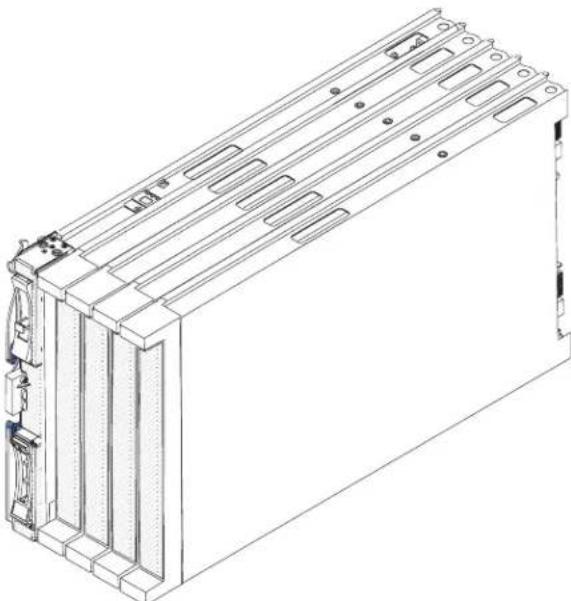
natural_image
Technical line drawing of a rectangular electronic device with multiple slots and mounting brackets (no text or symbols)ThemodelnumberandserialnumberareontheIDlabelonthesideofthecontrol panelonthefrontofthebladeserver,andonalabelonthesideoftheblade serverthatisvisiblewhenthebladeserverisnotintheBladeCenterunit.
Note: The illustrations in this document might differs slightly from the hardware.
Important: Donotplacethelabelonthebladeserveritselforinanywayblock theventilationholesonthebladeserver.
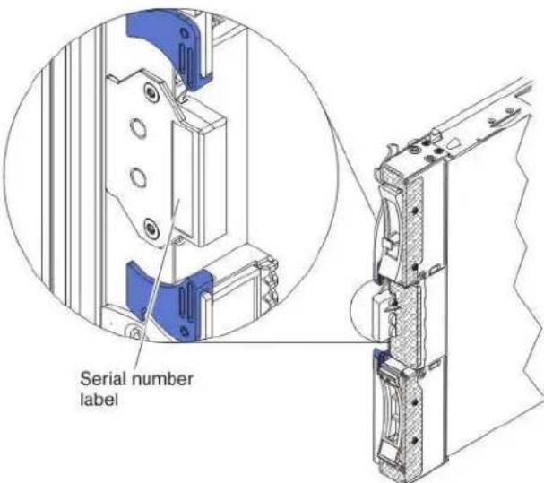
AsetofblanklabelsforyourbladeservercomeswiththeBladeCenterunit.When youinstallthebladeserverintheBladeCenterunit,writeidentifyinginformation onalabelandplacethelabelontheBladeCenterunitbezel.Seethe documentationforyourBladeCenterunitforrecommendedlabelplacement.
Relateddocumentation
Usethisinformationtoidentifyandlocaterelatedbladeserverdocumentation.
ThisInstallationandUser'sGuidecontainsgeneralinformationabouttheblade server,includinghowtoinstallsupportedoptionaldevicesandhowtoconfigure thebladeserver.Thefollowingdocumentationalsocomeswiththebladeserver:
•ProblemDeterminationandServiceGuide
ThisdocumentisinPortableDocumentFormat(PDF)ontheIBMDocumentation CD.Itcontainsinformationtohelpyousolveproblemsyourself, and it contains information for servicetechnicians.
•SafetyInformation
ThisdocumentisinPDFontheIBMDocumentationCD.Itcontainstranslated cautionanddangerstatements.Eachcautionanddangerstatementthatappears inthedocumentationhasanumberthatyoucanusetolocatethecorresponding statementinyourlanguageintheSafetyInformationdocument.
• Warranty and Support Information
ThisdocumentisinPDFontheIBMDocumentationCD.Itcontainsinformation aboutthetermsofthewarrantyandgettingserviceandassistance.
•EnvironmentalNoticesandUserGuide
ThisdocumentisinPDFontheIBMDocumentationCD.Itcontainstranslated environmentalnotices.
- IntegratedManagementModuleUser'sGuide
ThisdocumentisinPDFontheIBMWebsiteathttp://www.ibm.com/systems/support/. ThisdocumentexplainshowtousethefunctionsoftheIMM installedinandIBMserver.TheIMMworkswithIBMSystemxServerFirmware toprovidesystems-managementcapabilityforSystemxandBladeCenter servers.
•AdvancedManagementModuleMessagesGuide
ThisdocumentisinPDFontheIBMWebsiteathttp://www.ibm.com/systems/support/.Thisdocumentprovidesacompletelistofallnon-device-specificeventsandrecommendedactions,sortedbyeventID.Devicespecificeventinformationisinthedocumentationforthedevice.
Depending on your Blade Center product, additional documents might be included on the IBM Documentation CD. In addition to the documentation in this library, be sure to review the Planning and Installation Guide for your Blade Center unit for information to help you prepare for system installation and configuration. To check for updated documentation and technical updates, complete the following steps.
Note: Changes are made periodically to the IBM Website. The actual procedure might vary slightly from what is described in this document.
-
Gotohttp://www.ibm.com/systems/support/.
-
UnderProductsupport, clickBladeCenter.
-
Under Popular links, click Publications lookup.
-
From the Product family menu, select BladeCenter HS22.
TheIBMDocumentationCD
UsetheIBMDocumentationCDtoaccessthebladeserverdocumentationinPDF format.
You can run the IBMDocumentationCDonanypersonalcomputer that meets the hardware and software requirements.
TheIBMDocumentationCDcontainsdocumentationforyourbladeserverin PortableDocumentFormat(PDF)andincludestheIBMDocumentationBrowserto helpyoufindinformationquickly.
Hardwareandsoftwarerequirements
Use this information to determine the minimum hardware and software requirements for the bladeserver.
TheIBMDocumentationCDrequiresthefollowingminimumhardwareand software:
- MicrosoftWindowsXP, Windows2000, or RedHat Enterprise Linux5Server
•100MHzmicroprocessor
•32MBofRAM
- AdobeAcrobatReader3.0(orlater)orxpdf, which comes with Linux operating systems
UsingtheDocumentationBrowser
UsetheseinstructionstostarttheDocumentationBrowser.
Use the Documentation Browser to browse the content of the CD, read brief descriptions of the documents, and view documents, using Adobe Acrobat Reader or x pdf. The Documentation Browser automatically detects the regional settings in use in your system and display the documents in the language for that region (if available). If a document is not available in the language for that region, the English-language version is displayed.
UseoneofthefollowingprocedurestostarttheDocumentationBrowser:
- If Autostartisenabled, insert the CD into the CD drive. The Documentation Browser starts automatically.
- If Autostartisdisabledorisnotenabledforallusers, useoneofthefollowing procedures:
-If you are using a Windows operating system, insert the CD into the CD or DVD drive and click Start → Run. In the Open field, type e:\win32.bat
whereeisthedriveletteroftheCDorDVDdrive,andclickOK.
- If you are using Red Hat Linux, insert the CD into the CD or DVD drive; then, run the following command from the /mnt/cdrom directory: sh run linux.sh
Select your blade server from the Product menu. The Available Topics list displays allthedocumentsforyourbladeserver.Somedocumentsmightbeinfolders.A plussign(+)indicateseachfolderordocumentthathasadditionaldocuments underit.Clicktheplussigntodisplaytheadditionaldocuments.
When you select a document, a description of the document is displayed under TopicDescription. Toselect more than one document, press and hold the Ctrl key while you select the documents. Click View Book to view the selected document or documents in Acrobat Reader or x pdf. If you selected more than one document, all these selected documents are opened in Acrobat Reader or x pdf.
Tosearchallthedocuments,typeawordorwordstringintheSearchfieldandclickSearch.Thedocumentsinwhichthewordorwordstringappearsarelistedinorderofthemostoccurrences.Clickadocumenttoviewit,andpressCrtl+FtousetheAcrobatsearchfunction,orpressAlt+Ftousethexpdfsearchfunctionwithinthedocument.
ClickHelpfordetailedinformationaboutusingtheDocumentationBrowser.
Noticesandstatementsinthisdocument
Use this information to understand them most common documentation notices and statements and how they are used.
The caution and danger statements in this document are also in them multilingual Safety Information document, which is on the IBM Documentation CD. Each statement is numbered for reference to the corresponding statement in the Safety Information document.
The following notices and statements are used in this document:
•Note: Thesenoticesprovideimportanttips, guidance, or advice.
- Important: These notices provide information or advice that might help you avoid inconvenientorproblemsituations.
- Attention: These notices indicate possible damage to programs, devices, or data. An attention notice is placed just before the instruction or situation in which damage might occur.
- Caution: These statements indicate situations that can be potentially hazardous to you. A caution statement is placed just before the description of a potentially hazardous procedure step or situation.
- Danger: These statements indicate situations that can be potentially lethal or extremelyhazardoustoyou. Adangerstatementisplacedjustbefore the descriptionofapotentiallylethalorextremelyhazardousprocedurestepor situation.
Featuresandspecifications
Usehistabletoviewspecificinformationaboutthebladeserver,suchasblade serverhardwarefeaturesandthedimensionsofthebladeserver.
Notes:
-
Power, cooling, removable-mediadrives, external ports, and advanced system management are provided by the Blade Center unit.
-
The operating system in the bladeservermust provide USB support for the bladeservertertorecognize and use USB mediadrives and devices. The Blade Center unit uses USB for internal communications with these devices.
The following table is a summary of the features and specifications of the blade server.
Table1.Featuresandspecifications
| Microprocessor:Supportsuptotwomulti-coreIntelXeonmicroprocessors.Note:UsetheSetuputilitytodeterminethetypeandspeedofthemicroprocessorsinthebladeserver. | PredictiveFailureAnalysis(PFA) alerts:•Microprocessors•Memory•Storagedrives | Drives:Supportsuptotwohot-swap,smallformfactor(SFF)SerialAttachedSCSI(SAS)orSerialATA(SATA)storagedrives |
| Memory:•12dualinlinememorymodule(DIMM)connectors•Type:VeryLowProfile(VLP)double-datarate(DDR3)DRAM.Supports1GB,2GB,4GB,8GB,and16GBDIMMswithupto192GBoftotalmemoryonthesystemboard | Electricalinput:1 2 V d c | Size(Type7870andType1936):•Height:24.5cm(9.7inches)(6U)•Depth:44.6cm(17.6inches)•Width:2.9cm(1.14inches)•Maximumweight:4.8kg(10lb) |
| Integratedfunctions:•Horizontal-compact-form-factor(CFFh)expansioncardinterface•Vertical-combination-I/O(CIOv)expansioncardinterface•Localserviceprocessor:IntegratedManagementModule(IMM)withIntelligentPlatformManagementInterface(IPMI)firmware•IntegratedMatroxG200eVvideocontroller•LSI1064ESAScontroller•BroadcomBCM5709Sdual-portGigabitEthernetcontroller•Integratedkeyboard/video/mouse(cKVM)controllerthroughIMM•Lightpathdiagnostics•RS-485interfaceforcommunicationwiththemanagementmodule•Automaticserverrestart(ASR)•USB2.0forcommunicationwithcKVMandremovablemediadrives(anexternalUSBportisnotsupported)•SerialoverLAN(SOL)•Redundantbusesforcommunicationwithkeyboard,mouse,andremovablemediadrives | Environment:Airtemperature:-Bladeserveron:10°Cto35°C(50°Fto95°F).Altitude: 0 m to 914.4m(0ftto3000ft)-Bladeserveron:10°Cto32°C(50°Fto89.6°F).Altitude:914.4mto2133.6m(3000ftto7000ft)-Bladeserveroff:10°Cto43°C(50°Fto109.4°F).Altitude:914.4mto2133.6m(3000ftto7000ft)-Bladeservershipping:-40°Cto60°C(-40°Fto140°F)•Humidity:-Bladeserveron:8%to80%-Bladeserveroff:8%to80%-Bladeserverstorage:5%to80%-Bladeservershipment:5%to100%•Particulatecontamination:Attention:Airborneparticulatesandreactivegasesactingaloneorincombinationwithotherenvironmentalfactorssuchashumidityortemperaturemightposearisktotheserver.Forinformationaboutthelimitsforparticulatesandgases,see"Particulatecontamination"onpage85. | Size(Type1911):•Height:24.5cm(9.7in)•Depth:44.6cm(17.6in)•Width:14.5cm(5.71in)•Maximumweight:8.15kg(40.02lb)NEBSEnvironment•Airtemperature:-Bladeserveron:5°Cto40°C(41°Fto104°F).Altitude:-60mto1800m(-197ftto6000ft)-Bladeserveron:5°Cto30°C(41°Fto86°F).Altitude:1800mto4000m(6000ftto13000ft)-Bladeserveroff:-5°Cto55°C(23°Fto131°F).Altitude:-60mto1800m(-197ftto6000ft)-Bladeserveroff:-5°Cto45°C(23°Fto113°F).Altitude:1800mto4000m(6000ftto13000ft)-Bladeserverstorage:-40°Cto60°C(-40°Fto140°F)•Humidity:8%to85%•Particulatecontamination:Attention:Airborneparticulatesandreactivegasesactingaloneorincombinationwithotherenvironmentalfactorssuchashumidityortemperaturemightposearisktotheserver.Forinformationaboutthelimitsforparticulatesandgases,see"Particulatecontamination"onpage85. |
Whatyourbladeserveroffers
Yourbladeserveroffersfeatures,suchas,theIntegratedManagementModule,storagediskdrivesupport,IBM ® Director,IBMEnterpriseX-Architecture ® , microprocessortechnology,integratednetworksupport,I/Oexpansion,large system-memorycapacity,lightpathdiagnostics,PCIExpress,andpowerthrottling.
•IntegratedManagementModule(IMM)
TheIntegratedManagementModule(IMM)isonthesystemboardoftheblade server.TheIMMoperatesastheserviceprocessorforthebladeserverand performsseveraltasks,includingthefollowing:
-ProvidesRS-485interfacestotheAdvancedManagementModule
- I 2 CcompatibleTwoWireinterface
-LocalEnvironmentalMonitoring
-LocalLEDcontrol
-AutomaticServerRestart(ASR)
-Onechannel16550tosupportreadytosend(RTS)andcleartosend(CTS)modemcontrolpins(twoserialports)
-SerialoverLAN(SOL)
-IntelligentPlatformManagementInterface(IPMI)2.0compliant
-Remotepoweron/poweroffofaremotebladeserver
-Errorlogging
-Remotesystemsmanagement
-Bladeserveroversubscription
-Blowerspeedcontrol
- CPUthrottling
-Memorythrottling
-Integratedkeyboard/video/mouse(cKVM)
•Harddiskdrivesupport
The bladeserversupportsuptotwo2.5-inchhot-swapSASSFFharddisk drives,RAID0andRAID1support,upto300GBperdrive.
•IBM ® Director
IBMDirectorisaworkgroup-hardware-managementtoolthatyoucanuseto centrallymanageservers.Formoreinformation,seetheIBM ® Director documentationontheIBM ® DirectorCD.
•IBMEnterpriseX-Architecture
IBMEnterpriseX-Architecturetechnologycombinesproven,innovativeIBM designstomakeyourx86-processor-basedbladeserverpowerful,scalable,and reliable.Formoreinformation,seehttp://www.ibm.com/systems/x/hardware/enterprise/xarchitecture.html.
• IBMServerGuideSetupandInstallationCD
TheServerGuideSetupandInstallationCDprovidesprogramstohelpyousetup thebladeserverandinstallaWindowsoperatingsystem.TheServerGuide programdetectsinstalledoptionalhardwaredevicesandprovidesthecorrect configurationprogramsanddevicedrivers.Formoreinformationaboutthe ServerGuideSetupandInstallationCD,see"UsingtheServerGuideSetupand InstallationCD"onpage63.
•Integratednetworksupport
AllofthebladeservermodelscomewithanintegratedBroadcomdual-port GigabitEthernetcontroller.Thecontrollersupportsconnectionstoa10Mbps, 100Mbps,or1000MbpsnetworkthroughanEthernet-compatibleswitch moduleintheBladeCenterunit.ThecontrolleralsosupportsWakeonLAN technology.
®
•I/Oexpansion
Thebladeserverhasconnectorsonthesystemboardforoptionalexpansion cardsforaddingmorenetworkcommunicationcapabilitiestothebladeserver.
•Largesystem-memorycapacity
Thebladeserversystemboardsupportsupto96GBofsystemmemory.The memorycontrollerprovidessupportforuptotwelveindustry-standard registeredECCDDR3onVeryLowProfile(VLP)formfactorDIMMsinstalled onthesystemboard.ForthemostcurrentlistofsupportedDIMMs,seethe ServerProven® listathttp://www.ibm.com/servers/eserver/serverproven/ compat/us/.
•Lightpathdiagnostics
Lightpathdiagnosticsprovideslight-emittingdiodes(LEDs)tohelpyou diagnoseproblems. Formoreinformation,seetheProblemDetermination and ServiceGuide.
•PCIExpress
PCIExpressisaserialinterfacethatisusedforchip-to-chipinterconnectand expansionadapterinterconnect.Withthebladeexpansionconnectoryoucan adoptionII/Oandstoragedevices.
•Powerthrottling
Each bladeserverispoweredbytwoEnterpriseVoltageRegulator-Down (EVRD)11.0voltageregulators.Byenforcingapowerpolicyknownas power-domainoversubscription,theBladeCenterunitcansharethepowerload betweenwopowermodulestoensuresufficientpowerforeachdeviceinthe BladeCenterunit.Thispolicyisenforcedwhentheinitialpowerisappliedtothe BladeCenterunitorwhenabladeserverisinsertedintotheBladeCenterunit.
The following settings forth this policy are available:
-Redundantwithoutperformanceimpact
-Redundantwithperformanceimpact
-Nonredundant
YoucanconfigureandmonitorthepowerenvironmentbyusingtheAdvanced ManagementModule.Formoreinformationaboutconfiguringandusingpower throttling,seetheAdvanced-Management-Moduledocumentationor http://www.ibm.com/systems/support/.
Reliability, availability, and serviceability features
Reliability, availability, and serviceability features help to ensure the integrity of the datathatis stored in the bladeserver, the availability of the bladeserver when you need it, and the easewith which you can diagnose and correct problems.
Threeofthemostimportantfeaturesinserverdesignarereliability,availability,andserviceability(RAS).TheseRASfeatureshelptoensuretheintegrityofthedatathatisstoredinthebladeserver,theavailabilityofthebladeserverwhenyouneedit,andtheeasewithwhichyoucandiagnoseandcorrectproblems.
ThebladeserverhasthefollowingRASfeatures:
- CustomerupgradeofFlashROM-residentcodeanddiagnostics
•PowerPolicy24-hoursupportcenter
•VPDonMemory
- Customersupportcenter24hoursperday,7daysaweek.
- Customer-upgradeableUnifiedExtensibleFirmwareInterface(UEFI)codeand diagnostics
• DiagnosticsupportofEthernetcontrollers
•ECCprotectionontheL2cache
- Errorcodesandmessages
•Hot-swapSASstoragedrives
•IntegratedManagementModule(IMM)
•Lightpathdiagnosticsfeature
•Memoryparitytesting
•RegisteredECCDDR3memory
- Microprocessorbuilt-inself-test(BIST)duringpower-onself-test(POST)
•Microprocessorserialnumberaccess
•PCIPMI2.2
•PCIExpress1.0a
•POST
•ROMresidentdiagnostics
- ServiceprocessorthatcommunicateswiththeAdvancedManagementModuleto enableremotebladeservermanagement
•Systemerrorlogging
•WakeonLANcapability
•WakeonPCI(PME)capability
•WakeonUSB2.0capability
IBM® Director
UsethisinformationunderstandhowIBM ® Directorworkswiththeblade server.
WithIBM ® Director,anetworkadministratorcanperformthefollowingtasks:
•Viewthehardwareconfigurationofremotesystems,indetail
•Monitortheusageandperformanceofcriticalcomponents,suchas microprocessors,disks,andmemory
- CentrallymanageindividuallargegroupsofIBMandnon-IBM x86-processor-basedservers,desktopcomputers,workstations,andnotebook computersonavarietyofplatforms
IBM® Directorprovidesacomprehensiveentry-levelworkgrouphardware manager.Itincludesthefollowingkeyfeatures:
- Advancedself-managementcapabilitiesformaximumsystemavailability.
- Multipleoperating-systemplatformsupport,includingMicrosoftSmallBusiness Server,MicrosoftWindows2000Server,WindowsServer2003,AIX ,i5/OS TM , RedHatLinux,SUSELinux,andVMware.Foracompletelistofoperating systemsthatsupportIBMDirector,seethelBMDirectorCompatibility Document.ThisdocumentisinPortableDocumentFormat(PDF)at http://www.ibm.com/systems/management/director/resources/.Itisupdated every6to8weeks.
- SupportforIBMandnon-IBMservers,desktopcomputers,workstations,and notebookcomputers.
•Supportforsystems-managementindustrystandards.
- Integrationintoleadingworkgroupandenterprisesystems-management environments.
- Easeofuse, training, and setup.
IBM ® Directoralsoprovidesanextensibleplatformthatsupportsadvancedserver toolsthataredesignedtoreducethetotalcostofmanagingandsupporting networkedsystems.BydeployingIBM ® Director,youcanachievereductionsin ownershipcoststhroughthefollowingbenefits:
- Reduced downtime
- IncreasedproductivityofITpersonnelandusers
•Reducedserviceandsupportcosts
FormoreinformationaboutIBMDirector,seetheIBMSystemsDirector InformationCenterathttp://publib.boulder.ibm.com/infocenter/eserver/v1r2/topic/diricinfo_all/diricinfoparent.html andtheIBMxSeries SystemsManagement Webpageathttp://www.ibm.com/servers/eserver/xseries/systems_management/,whichpresentsanoverviewofIBMSystemsManagement andIBM® Director.
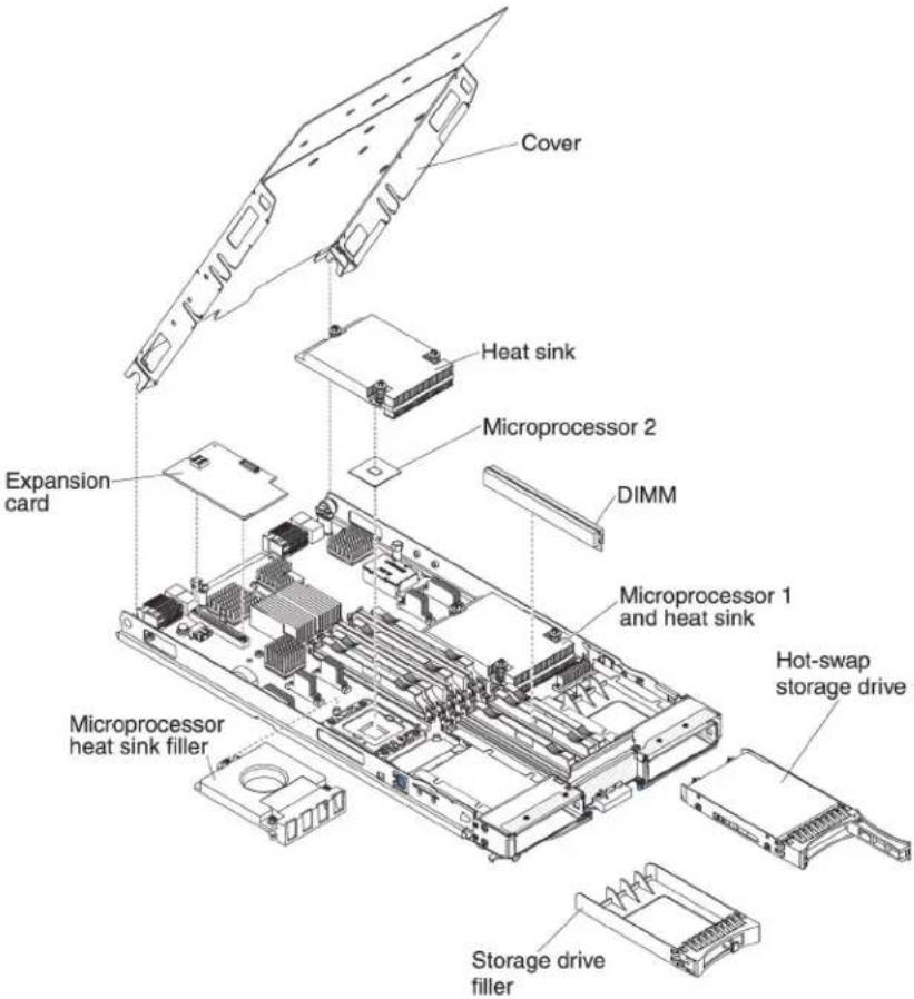
Majorcomponentsofthebladeserver
Use this information to locate them major components on the bladeserver. The major component of the bladeserver include Field Replaceable Units (FRUs), Customer Replaceable Units (CRUs), and optional devices.
The following illustrations show sthemajor component of the bladeserver.
Chapter2.Power,controls,andindicators
Use this information to view power features, turn on and turn off the bladeserver, and view the function of the controls and indicators.
BladeservercontrolsandLEDs
Use this information for details about the controls and LEDs on the bladeserver.
The following illustration identifies the buttons and information LEDs on the blade-server control panel.
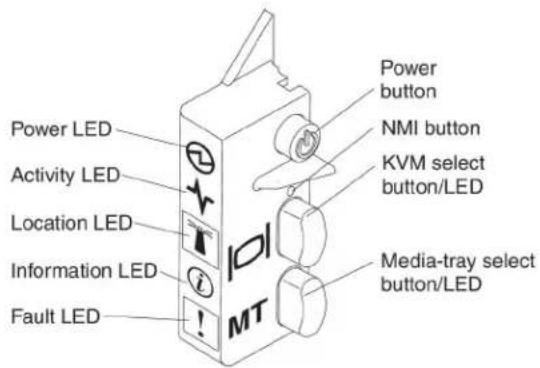
Power-onLED: ThisgreenLED indicates the power status of the blades server in the following manner:
- Flashingrapidly:Whiletheserviceprocessorinthebladeserverisinitializing andsynchronizingwiththemanagementmodule,thepower-onLEDflashes rapidly,andthepower-controlbuttononthebladeserverdoesnotrespond.This processcantakeapproximatelytwominutesafterthebladeserverhasbeen installed.IftheLEDcontinuestoflashrapidly,thebladeservermightnothave powerpermissionsassignedtoitthroughtheAdvancedManagementModule, theBladeCenterunitdoesnothaveenoughpowertoturnonthebladeserver, ortheserviceprocessor(IMM)onthebladeserverisnotcommunicatingwith theAdvancedManagementModule.
- Flashingslowly: The bladeserverhaspowersuppliedandisreadytobeturned on.
•Litcontinuously:Thebladeserverhaspowerandisturnedon.
ActivityLED: WhenthisgreenLEDislit, it indicates that there is activity on the external storage device or network.
LocationLED: Thesystemadministrator can remotely turn on this blue LED to aid invisually locating the blades server. Whenthis LED dislit, the location LED on the Blade Center unit is alsolit. Thelocation LED can be turned off through the Advanced-Management-Module Web interface through IBM Director Console. Formoreinformation about the Advanced-Management-Module Web interface, see http://www.ibm.com/systems/management/. Formoreinformation about IBM Director, seethedocumentation on the IBM Director CD that comes with the
server,orvisittheIBM ® DirectorInformationCenterathttp://publib.boulder.ibm.com/infocenter/director/v6r1x/index.jsp.
InformationLED: WhenthisamberLEDislit, it indicates that information about a system event in the blades server has been placed in the Advanced Management-Module event log. The information LED can be turned off through the Advanced Management Module CLI, SNMP, or Web interface through IBM DirectorConsole. Form more information about the Advanced Management Module Web interface, see http://www.ibm.com/systems/management/. Form more information about IBM Director, seethedocumentation on the IBM DirectorCD that comes with the server, or visit the IBM Director Information Center at http://publib.boulder.ibm.com/infocenter/director/v6r1x/index.jsp.
FaultLED: WhenthisamberLEDislit, it indicates that a system error has occurred in the bladeserver. The blade-error LED turn soffonly after the error is corrected.
Power-controlbutton:Pressthisbuttontoturnonorturnoffthebladeserver.
Note: The power-control button has effect only if local power control is enabled for the blades server. Local power control is enabled and disabled through the Advanced-Management-Module Web interface.
NMIbutton(recessed): Thenonmaskableinterrupt(NMI)dumpsthepartition. Use this recessed button only as directed by IBMSupport.
Note: You can also send an NM event to these selected blades server remotely using the AMM. Form more information, seethe Blade Center Advanced Management Module User's Guide.
Keyboard/video/mouse(KVM)selectbutton:Pressthisbuttontoassociatethe sharedBladeCenterunitkeyboardport,videoport,andmouseportwiththeblade server.TheLEDonthisbuttonflasheswhiletherequestisbeingprocessedand thenislitwhentheownershipofthekeyboard,video,andmousehasbeen transferredtothebladeserver.Itcantakeapproximately20secondstoswitchthe keyboard,video,andmousecontroltothebladeserver.
UsingakeboardthatisdirectlyattachedtotheAdvanced-Management-Module, youcanpresskeyboardkeysinthefollowingsequencetoswitchKVMcontrol betweenbladeserversinsteadofusingtheKVMselectbutton:
NumLockNumLockblade_server_numberEnter blade_server_numberisthettwo-digitnumberoftheblade-serverbayinwhich thebladeserverisinstalled.Abladeserverthatoccupiesmorethanone blade-serverbayisidentifiedbythelowestbaynumberthatitoccupies.
If there is no response when you press the KVM select button, you can use the Advanced-Management-Module Web interface to determine whether local control has been disabled on the blades server. See http://www.ibm.com/systems/management/formoreinformation.
Notes:
-
The operating system in the bladeserver must provide USB support for the bladeserver to recognize and use the keyboard and mouse, even if the keyboard and mouse have PS/2-style connectors.
-
If you install as supported Microsoft Windows operating system on the blade server while it is not the current owner of the keyboard, video, and mouse, a delay of up to 1 minute occurs the first timethat your switch the keyboard, video, and mouse to the blades server. All subsequent switching takes place in thenormal KVM switching timeframe (upto 20 seconds).
Media-trayselectbutton:PressthisbuttontoassociatethesharedBladeCenterunitmediatray(removable-mediadrives)withthebladeserver.TheLEDonthebuttonflasheswhiletherequestisbeingprocessedandthenislitwhentheownershipofthemediatrayhasbeentransferredtothebladeserver.Itcantakeapproximately20secondsfortheoperatingsysteminthebladeserververtorecognizethemediatray.
Ifthereisnoresponsewhenyoupressthemedia-trayselectbutton,youcanuse theAdvanced-Management-ModuleWebinterfacetodeterminewhetherlocal controlhasbeendisabledonthebladeserver.
Note: The operating system in the bladeserver must provide USB support for the bladeserver vertorecognize and use theremovable-mediated drives.
The following illustration identifies the information LED on the SAShot-swap hard disk drive.
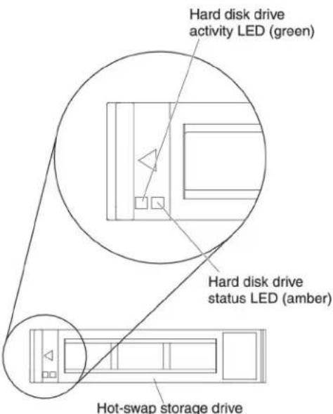
HarddiskdriveactivityLED(green): WhenthisgreenLEDislit, it indicates that there is activity on the storage drive.
HarddiskdrivestatusLED(amber): WhenthisamberLEDislit, it indicates that an error has occurred with the storage drive. The LED turn soffonly after the error is corrected.
Turningonthebladeserver
Usethisinformationtoturnonthebladeserver.
AfteryouconnectthebladeservertopowerthroughtheBladeCenterunit,the bladeservercanstartinanyofthefollowingways:
- Youcanpressthepower-controlbuttononthefrontofthebladeserver(see "BladeservercontrolsandLEDs" onpage15)tostartthebladeserver.
Notes:
-
Waituntilthepower-onLEDonthebladeserverflashesslowlybeforeyou pressthepower-controlbutton. While the service processor in the blade server is initializing and synchronizing with the management module, the power-on LED flashes rapidly, and the power-control button on the blade server does not respond. This process can take approximately two minutes after the blade server has been installed.
-
While the bladeserveris starting, the power-on LED on the front of the bladeserveris lit and does not flash. See "Bladeservercontrols and LEDs" on page 15 for the power-on LED states.
- Ifapowerfailureoccurs, the BladeCenterunit and the bladeservercan be configured to start automatically when power is restored through the Advanced Management Module.
- Youcanturnonthebladeserverremotelybyusingthemanagementmodule.
- If the bladeserverisconnectedtopower(thepower-onLEDisflashingslowly), the bladeserveriscommunicatingwiththemanagementmodule,theoperating systemsupportstheWakeonLANfeature,andtheWakeonLANfeaturehas notbeendisabledthroughthemanagementmodule,theWakeonLANfeaturecanturnonthebladeserver.
Turningoffthebladeserver
Usethisinformationtoturnoffthebladeserver.
Whenyouturnoffthebladeserver,itisstillconnectedtopowerthroughthe BladeCenterunit.Thebladeservercanrespondtorequestsfromtheservice processor,suchasaremoterequesttoturnonthebladeserver.Toremoveall powerfromthebladeserver,youmustremoveitfromtheBladeCenterunit.Shut downtheoperatingsystembeforeyouturnoffthebladeserver.Seethe operating-systemdocumentationforinformationaboutshuttingdownthe operatingsystem.
Thebladeservercanbeturnedoffinanyofthefollowingways:
- Youcanpressthepower-controlbuttononthebladeserver(see"Bladeserver controlsandLEDs"onpage15). This starts an orderly shutdown of the operatingsystem, if this feature is supported by the operatingsystem.
- If the operating system stops functioning, you can press and hold the power-control button form more than 4 second to turn off the bladeserver.
- Themanagementmodulecanturnoffthebladeserverthroughthe Advanced-Management-ModuleWebinterface.Foradditionalinformation,see theIBMBladeCenterManagementModuleUser'sGuideorgoto http://www-03.ibm.com/systems/management/formoreinformation.
Bladeserverconnectors
Use this information to locate blades servers system-board components and connectors for optional devices.
The following illustrations show the system-board components, including connectors for user-installable optional devices, in the bladeserver.

BladeCenterGPUexpansionunitLED
The following illustration identifies the default LED on the front of the Blade Center GPU expansion (BGE) unit.
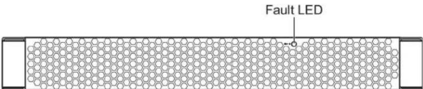
FaultLED: WhenthisamberLEDislit, it indicates that an error has occurred in the expansion blade. The expansion blade error LED turn soffonly after the error is corrected.
Ifanerroroccursintheexpansionblade,thefaultLEDonthebladedeviceon whichtheexpansionbladeisinstalleddisalsolit.Additionalinformationaboutthe errorsprovidedbythelight-pathLEDsintheexpansionblade(seetheProblem DeterminationandServiceGuidethatcomeswithyourserverformoreinformation).
Chapter3.Installingoptions
Use this information for instructions about installing optional hardware devices in the bladeserver. Some option-removal instructions are provided in case you have to remove one option to install another.
Installationguidelines
Usetheseguidelinesbeforeyouinstallthebladeserveroroptionaldevices.
Beforeyouinstalloptionaldevices,readthefollowinginformation:
- Before you begin, read "Safety" on page and "Handling static-sensitive devices" on page 22. This information will help you work safely.
- When you install your new bladeserver, take the opportunity to download and apply them most recent firmware updates. This step will help to ensure that any known issues are addressed and that your bladeserver is ready to function at maximum level sof performance.
Note: Changes are made periodically to the IBM Website. The actual procedure might vary slightly from what is described in this document.
Todownloadfirmwareupdatesforyourbladeserver,completethefollowing steps:
-
Gotohttp://www.ibm.com/systems/support/.
-
UnderProductsupport, clickBladeCenter.
-
Under Popular links, click Software and device drivers.
-
Click BladeCenter HS22 to display the matrix of downloadable files for the bladeserver.
- Observegoodhousekeepingintheareawhereyouareworking.Placeremoved coversandotherpartsinasafeplace.
- Backupallimportantdatabeforeyoumakechangestodiskdrives.
- Before you remove abladeserver from the BladeCenterunit, you must shut down the operatingsystem and turn off the bladeserver. You donothaveto shutdown the BladeCenterunit itself.
- Blueonaccomponentindicatestouchpoints,whereyoucangripthecomponent toremoveitfromorinstallitinthebladeserver,openorclosealatch,andso on.
- Orangeancomponentoranorangelabelonornearacompontindicates that the component can be hot-swapped, which means that if the server and operating systems support hot-swap capability, you can remove or install the component while the server is running. (Orangecan also indicate to touch points on hot-swap components.) Seethe instructions for removing or installing a specific hot-swap component for any additional procedure that you might have to perform before you remove or install the component.
- Foralistofsupportedoptionaldevicesforthebladeserver,see http://www.ibm.com/servers/eserver/serverproven/compat/us/.
Systemreliabilityguidelines
Use this information to make sure that the blades server meet the proper cooling and reliability guidelines.
To help makes sure that proper cooling and system reliability requirements are met, review the following guidelines:
•Toensurepropercooling, donotoperatetheBladeCenterunitwithoutabla de server, expansionunit, orbladefillerinstalledineachblade-serverbay. Seethe documentation for your BladeCenterunit for additional information.
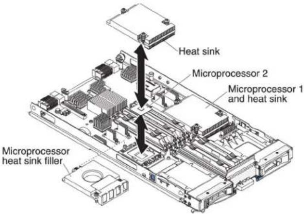
• Each microprocessor socket always contain either a microprocessor dust cover and heatsink filler or a microprocessor and heatsink. If the bladeserver has only onemicroprocessor, it must be installed in microprocessor socket 1.
•EachDIMMsocketalwayscontainsamemorymoduleorfiller.
•Eachhot-swapSASbaycontainsaSASstoragedriveorfiller.
- Makesurethattheventilationholesonthebladeserverarenotblocked.
- The bladeserverbatterymustbeoperational. If the battery becomes defective, replace it immediately. For instructions, seethe Problem Determination and Service Guide.
Handlingstatic-sensitivedevices
Usethisinformationtoobservethestatic-sensitivedevicerequirements.
Attention: Staticelectricity candamagethebladeserverandotherelectronic devices. To avoid damage, keep static-sensitive devices in their static-protective packages until you are ready to install them.
Toreducethepossibility of damage from electrostatic discharge, observ the following precautions:
- WhenyouworkonaBladeCenterunitthathasanelectrostaticdischarge(ESD) connector,useawriststrap,especiallywhenyouhandlemodules,optional devices,orbladeservers.Toworkcorrectly,thewriststrapmusthaveagood contactatbothends(touchingyourskinatoneendandfirmlyconnectedtothe ESDconnectoronthefrontorbackoftheBladeCenterunit).
- Limityourmovement.Movementcancausestaticelectricitytobuilduparound you.
- Handlethedevicecarefully, holdingitbyitsedgesoritsframe.
- Donottouchsolderjoints,pins,orexposedcircuitry.
- Donotleavethedevicewhereotherscanhandleanddamageit.
- While the device is still in its static-protective package, touch it to an unpainted metalpartoftheBladeCenterunitoranyunpaintedmetalsurfaceonanyother groundedrackcomponentintherackinwhichyouareinstallingthedevicefor atleast2seconds.Thisdrainsstaticelectricityfromthepackageandfromyour body.
- Removethedevicefromitspackageandinstallitdirectlyintothebladeserver withoutsettingdownthedevice.Ifitisnecessarytosetdownthedevice,putit backintoitsstatic-protectivepackage.Donotplacethedeviceontheblade servercoveroronametalsurface.
•Takeadditionalcarewhenyouhandledevicesduringcoldweather.Heating reducesindoorhumidityandincreasesstaticelectricity.
RemovingthebladeserverfromtheBladeCenterunit
UsetheseinstructionstoremovethebladeserverfromtheBladeCenterunit.
The following illustrations show show to remove a single-width type of blade server or blade filler from a Type 8677 Blade Center unit. The appearance of your Blade Center unit might be different; seethedocumentation for your Blade Center unit for additional information.
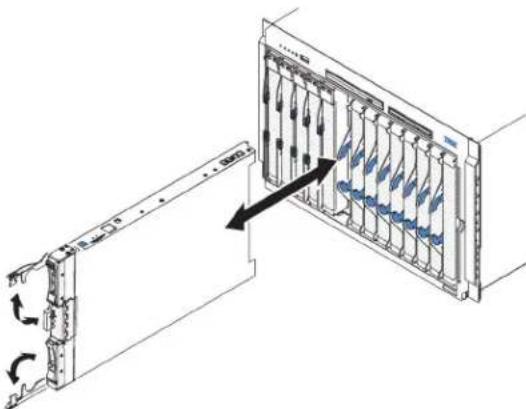
natural_image
Diagram of a server rack with internal components and directional arrows indicating movement (no text or symbols)Attention:
• Tomaintainpropersystemcooling, donotoperatetheBladeCenterunitwithout abladeserver, expansionunit, orfillermoduleinstalledineachbladeserver bay.
- Whenyouremovethebladeserver,notetheblade-serverbaynumber. Reinstallingabladeserverintoadifferentbladeserverbayfromtheoneitwas removedfromcanhaveunintendedconsequences.Someconfiguration informationandupdateoptionsareestablishedaccordingtoblade-serverbay number;ifyoureinstallthebladeserverintoadifferentbay,youmighthaveto reconfigurethebladeserver.
Toremovethebladeserver,completethefollowingsteps:
-
If the bladeserverisoperating, shutdowntheoperatingsystem(seethe documentation for youroperatingsystem form more information).
-
If the server is still on, pressthe power-control button for four second st oturn off the bladeserver (see "Turning off the bladeserver" on page 18 form more information).
Attention: Waitatleast30seconds, until the storage devices stop spinning, before you proceed to then next step.
- Openthetworeleasehandlesasshownintheillustration. Thebladeserver movesoutofthebladeserverbayapproximately0.6cm(0.25inch).
4.Pullthebladeserveroutofthebay.
Attention: Two people are required to remove a Type 1911 bladeserverout of the bay.
Statement4:(forType1911)

≥ 18kg(39.7lb)
CAUTION:
Usesafepracticeswhenlifting.
- Place either ablade filler or another bladeserver in the bladeserver bay within 1 minute.
Removingthebladeservercover
Usetheseinstructionstoopenthebladeservercover.
The following illustrations show show to open the cover on the bladeserver.
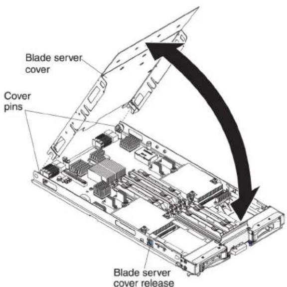
Toopenthebladeservercover,completethefollowingsteps.
-
Before you begin, read "Safety" on page and "Installation guidelines" on page21.
-
If the bladeserver is installed in a BladeCenter unit, remove it (see "Removing the bladeserver from the BladeCenter unit" on page 23 for instructions).
-
Carefully lay the blades server on a flat, static-protective surface, with the cover side up.
-
Pressthebladeservercoverreleaseoneachsideofthebladeserveror expansionunitandliftthecoveropen,asshownintheillustration.
5.Laythecoverflat,orliftitfromthebladeserverandstoreforfutureuse.
Statement21

CAUTION:
Hazardousenergyispresentwhenthebladeserverisconnectedtothepower source.Alwaysreplacethebladecoverbeforeinstallingthebladeserver.
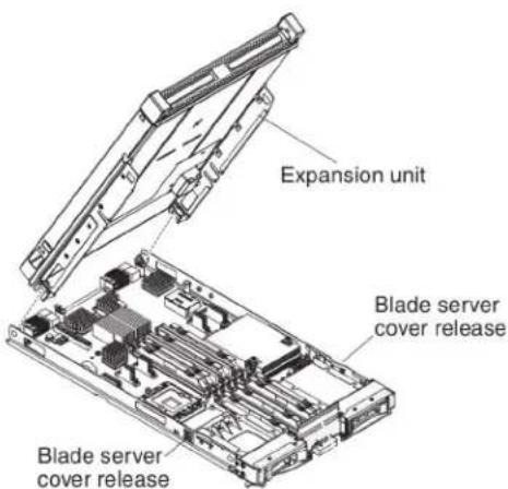
Installinganoptionalexpansionunit
Usetheseinstructionstoinstallanoptionalexpansionunit.
Attention: If a horizontal combination form-factor (CFFh) expansion card is installed on the blades serversystemboard, you cannot install an optional expansion unit.
Notes:
- All devices should be installed in an expansion unit before attaching it to the bladeserver.
- After you install one or more expansion units on your bladeserver, the combined bladeserver and expansion units together occupy adjacent blade bays in the Blade Center unit. Enough power modules must be installed in the Blade Center unit topower blade bays in which you install the bladeserver and expansion units.
- The following illustrations shows an optionalexpansionunitinabladeserver.
- The illustrations in this document might differs slightly from your hardware.
Toinstallanoptionalexpansionunit,completethefollowingsteps.
-
Before you begin, read "Safety" on page and "Installation guidelines" on page 21. To determine the type and number of expansion units that can be installed by your blades server, see http://www.ibm.com/servers/eserver/serverproven/compat/us/.
-
If the bladeserver is installed in a BladeCenter unit, remove it (see "Removing the bladeserver from the BladeCenter unit" on page 23 for instructions).
-
Removethecoverfromthebladeserverortheexpansionunit(see"Removing thebladeservercover" onpage24.
-
Locatethebladeexpansionconnectorthebladeserversystemboardorthe expansionunitandremovethecoverifoneisinstalled(see"Bladeserver connectors"onpage19).
-
Touch the static-protective package that contains the optionale expansion unit to any unpainted metal surface on the Blade Center unit or any unpainted metal surface on any other grounded rack component; then, remove the optional expansion unit from the package.
-
Orienttheoptionalexpansionunitasshownintheillustration.
-
Lowertheexpansionunitsothattheslotsattherearslidedownontothe coverpinsattherearofthebladeserver; then, pivottheexpansionunitdown ontothebladeserver.
-
If the expansion unit has an extraction device (such as a thumbscrew, lever), use it to fully engage the expansion unit on the blades server; otherwise, press the expansion unit firmly into the closed position until it clicks into place. To install an optional GPU adapter into a GPU expansion unit, see "Installing a GPU adapter in the Blade Center GPU expansion unit" on page 34. To install an option into another type of expansion unit, referto the documentation provided with the expansion unit.
-
If additional expansion units are being installed, repeat steps 4 through 8 for each expansion blade; otherwise continue with step 11.
-
Follow the instructions provided with the expansion unit to install an option in the expansion unit.
-
If you have other device to install or remove, do so now; otherwise, goto "Completing the installation" on page 54.
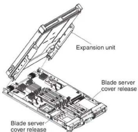
Removinganoptionalexpansionunit
Usetheseinstructionstoremovetheoptionalexpansionunitfromthebladeserver.
Note: For instruction on removing an expansion unit from the IBM Web Sphere Data Power Integration Blade X150BType4195 appliance, seethel Installation and User's Guidethat camewith the blade appliance.
Toremoveanoptionalexpansionunit,completethefollowingsteps:
-
Before you begin, read "Safety" on page and "Installation guidelines" on page 21.
-
If the bladeserver is installed in a BladeCenter unit, remove it (see "Removing the bladeserver from the BladeCenter unit" on page 23 for instructions).
-
Carefully lay the blades server on a flat, static-protective surface, with the cover side up.
-
Removethebladeservercover, ifoneisinstalled (see "Removingtheblade servercover" on page 24 for instructions).
-
Removetheexpansionunit:
a. If the expansion unit has an extraction device, use the extraction device to disengage the expansion unit from the blades server. These extraction devices can be of several types, including thumbs screws or levers. See the instructions provided with the expansion unit for detailed instructions for removing the expansion unit.
b. If the expansion unit does not have an extraction device, press the blade server cover release one each side of the blades server and lift the expansion unit from the blades server.
c. Rotatetheexpansionunitopen; then, lifttheexpansionunitfromtheblade server.
- If you are instructed to return the expansion unit, remove from any options that you have installed; then, follow all packaging instructions, and use any packaging materials for shipping that aresupplied to you.
Installingahot-swapstoragedrive
Usetheseinstructionstoinstallahot-swapstoragedriveintothebladeserver.
ThebladeserverhastwoSASstoragebaysforinstallinghot-swapstoragedrives, suchasahot-swapSASHarddiskdrive.Onestorgedrivemightalreadybe installedinthebladeserverinstoragebay0.Ifthebladeserverisequippedwith onestorgagedrive,youcaninstallanadditionaldriveinstoragebay1.Theblade serversupportsusingRAID0orRAID1whentwostorgagedrivesofthesame interfacetypeareinstalled.See"ConfiguringaRAIDarray"onpage67for informationaboutSASRAIDconfiguration.
Toinstallahot-swapstoragedriveordrivefiller,completethefollowingsteps.

- Before you begin, read "Safety" on page and "Installation guidelines" on page21.
2.IdentifytheSASstoragebay(storagebay0orstoragebay1)inwhichthe hot-swapstoragedrivewillbeinstalled(see"Bladeserverconnectors"onpage [19]). - Ifastorage-bayfillerisinstalled, removeitfromthebladeserverbypullingthe releaseleverandslidingthefillerawayfromthebladeserver(see"Removinga hot-swapstoragedrive").
- Touch the static-protective package that contains the hot-swap storage driveto any unpainted metal surface on the Blade Center unit or any unpainted metal surface on any other grounded crack component; then, remove the hard disk drive from the package.
- Open there lease lever on the hot-swap storage drive and slid the drive into the storage bay until it is firmly seated in the connector.
- Lockthehot-swapstoragedriveintoplacebyclosingthereleaselever.
If you have other device to install or remove, do so now; otherwise, goto "Completing the installation" on page 54.
Removingahot-swapstoragedrive
Usethisinformationtoremoveahot-swapstoragedrive.
ThebladeserverhastwoSAShot-swapstoragebaysforinstallingorremoving hot-swapstoragedevices,suchasaSASstoragedrive.Toremoveahot-swaphard diskdriveordrivefiller,completethefollowingsteps.

-
Before you begin, read "Safety" on page and "Installation guidelines" on page21.
-
Pressthereleaselatch(orange)onthestoragedrivetoreleasethedrivehandle.
-
Pull therelease handle to removethedrive from the storage bay.
Installingamemorymodule
Usetheseinstructionstoinstallmemorymodulesinthebladeserver.
Thebladeserverhasatotaloftwelvedirectinlinememorymodule(DIMM)slots. Thebladeserversupportsverylowprofile(VLP)DDR3DIMMswitherrorcode correction(ECC)in1GB,2GB,4GB,8GB,and16GBcapacities.Foracurrentlist ofsupportedDIMMsforthebladeserver,seehttp://www.ibm.com/servers/eserver/serverproven/compat/us/.
AfteryouinstallorremoveaDIMM,youmustchangeandsavethenew configurationinformationbyusingtheSetuputility.Whenyouturnontheblade server,amessageindicatesthatthememoryconfigurationhaschanged.Startthe SetuputilityandselectSaveSettings(see"Setupputilitymenu"onpage60for moreinformation)tosavechanges.
Thememoryisaccessedinternallythroughthesystemusingsixchannels.Each channelcontainstwoDIMMconnectors.Thefollowingtablelistseachchanneland whichDIMMconnectorsbelongtothechannel.
Table2. Memorychannelconfiguration
| MemorychannelDIMMconnector | |
| Channel0DIMMconnector1and2 | |
| Channel1DIMMconnector5and6 | |
| Channel2DIMMconnector3and4 | |
| Channel3DIMMconnector7and8 | |
| Channel4DIMMconnector11and12 | |
| Channel5DIMMconnector9and10 |
DependingonthememorymodethatissetintheSetuputility,thebladeserver cansupportaminimumof1GBandamaximumof48GBofsystemmemoryon thesystemboardinabladeserverwithoneprocessor.Iftwomicroprocessorsare installed,thebladeservercansupportaminimumof2GBandamaximumof96 GBofsystemmemory.Therearetwodifferentmemorymodes:
- Independent channel mode: Independent channel mode gives a maximum of 96 GBofusablememorywithoneCPUinstalled,and192GBofusablememory with2CPUsinstalled(using16GBDIMMs).TheDIMMscanbeinstalled withoutmatchingsizes.Seethetablebelowforthememoryinstallationorder.
Table3.Systemmemoryconfigurationforindependentchannelmode(1microprocessor)
| Installed memory | DIMMsocket | |||||||||||
| 1 | 2 | 3 | 4 | 5 | 6 | 7 | 8 | 9 | 1 | 0 | 1 | |
| 1DIMMX | ||||||||||||
| 2DIMMs | X | X | ||||||||||
| 3DIMMs | X | X | X | |||||||||
| 4 DIMMs | X | X | X | X | ||||||||
| 5 DIMMs | X | X | X | X | X | |||||||
| 6DIMMs | X | XXXXX | ||||||||||
Table4. Systemmemoryconfigurationforindependentchannelmode(2microprocessors)
| Installed memory | DIMMsocket | |||||||||||
| 1 | 2 | 3 | 4 | 5 | 6 | 7 | 8 | 9 | 1 | 0 | 1 | |
| 2DIMMsXX | ||||||||||||
| 3DIMMsXXX | ||||||||||||
| 4DIMMsXXXX | ||||||||||||
| 5DIMMsXXXX | ||||||||||||
| 6DIMMsXXXXXX | ||||||||||||
| 7DIMMsXXXXXXXX | ||||||||||||
| 8DIMMsXXXXXXXX | ||||||||||||
| 9DIMMsXXXXXXXX | ||||||||||||
| 10DIMMsXXXXXXXX | XXX | |||||||||||
| 11DIMMsXX | X | X | X | X | X | X | X | X | X | X | ||
| 12DIMMsXX | XXXXXXXX | XXXXX | ||||||||||
- Mirrored channel mode: In mirrored channel mode, channels 2 and 5 are unused. The memory contents on channel 0 are duplicated in channel 1, and the memory contents of channel 3 are duplicated in channel 4. The effective memory available to the system is only half of that installed. The maximum available memory (with 16 GB DIMMs) is 32 GB for a single CPU system and 64 GB for a dual CPU system.
Important: The memory configuration of channel 0 must match that of channel 1, and the memory configuration of channel 3 must match that of channel 4. For example, if a 4 GB Dual Rank DIMM is installed into the DIMM2 connector, then a 4 GB Dual Rank DIMM must also be installed into the DIMM6 connector. Table 2 on page 29 lists each channel and which DIMM connectors belong to the channel.
The following table shows the order that memory DIMMs are installed to use a mirrored channel mode.
Table5. Systemmemoryconfigurationformirroredchannelmode(1microprocessor)
| Installedmemory | DIMMsocket | |||||||||||
| 1 | 2 | 3 | 4 | 5 | 6 | 7 | 8 | 9 | 1 | 0 | 1 | |
| 2DIMMsXX | ||||||||||||
| 4DIMMsXX | XX | |||||||||||
Table6. System memory configuration form mirrored channel mode (2 microprocessors)
| Installedmemory | DIMMsocket | |||||||||||
| 1 | 2 | 3 | 4 | 5 | 6 | 7 | 8 | 9 | 1 | 0 | 1 | |
| 4DIMMsXXXX | ||||||||||||
| 6DIMMsXX | XXXX | |||||||||||
| 8DIMMsXX | XXXX | XX | ||||||||||
- Spare channel mode: In spare channel mode, channel 2 is the spare of the active channels 0 and 1. The spare channel is not available as active memory. The maximum memory available (with 16 GB DIMMs) is 64 GB in a single CPU system and 128 GB in a dual CPU system. All three channels must have
identical population with regard to size and organization. DIMM with a channel on the alphabet of identical. The population ordering for spare channel mode is shown in the table below.
Note: SparechannelmodeisonlysupportedifthebladeserverhasanIntel Xeon5600seriesmicroprocessor. Use the Setuputility to view the system summary and verify the type of microprocessor installed in your bladeserver (see "Using the Setuputility" on page 60).
The following tables show the order that memory DIMMs are installed to use spare channel mode.
Table7. Systemmemoryconfigurationforsparechannelmode(1microprocessor)
| Installed memory | DIMMsocket | |||||||||||
| 1 | 2 | 3 | 4 | 5 | 6 | 7 | 8 | |||||
| 3DIMMsXXX | ||||||||||||
| 6DIMMsXX | XXX | X | ||||||||||
Table8. Systemmemoryconfigurationforsparechannelmode(2microprocessors)
| Installed memory | DIMMsocket | |||||||||||
| 1 | 2 | 3 | 4 | 5 | 6 | 7 | 8 | 9 | 10 | 11 | 12 | |
| 6DIMMs | XX | XXX | X | |||||||||
| 9 DIMMs | X | X | X | X | X | X | X | X | X | |||
| 12 DIMMs | X | X | X | X | X | X | X | X | X | X | X | X |
ToinstallaDIMM, completethefollowingsteps:
-
Before you begin, read "Safety" on page and "Installation guidelines" on page 21.
-
ReadthedocumentationthatcomeswiththeDIMMs.
-
If the bladeserver is installed in a BladeCenter unit, remove it (see "Removing the bladeserver from the BladeCenter unit" on page 23 for instructions).
-
Carefully lay the blades server on a flat, static-protective surface.
-
Openthebladeservercover(see "Removingthebladeservercover" on page 24 for instructions).
-
If an expansion unit is installed and you are installing DIMM son the system board, remove the expansion unit (see "Removing an option a expansion unit" on page 26).
-
LocatetheDIMMconnectors(see "Bladeserverconnectors" onpage19). DeterminewhichDIMMconnectoryouwillbeinstallingmemoryinto.
-
IfaDIMMfilleroranothermemorymoduleisalreadyinstalledintheDIMM connector,removeit(see"Removingamemorymodule" onpage33).
Note: ADIMMorDIMMfillermustoccupyeachDIMMsocketbeforethe bladeserveristurnedon.
- If you are installing a DIMMinDIMMconnector seventh through twelve, use your fingerstolift the DIMMaccessdoor.

- Touch the static-protective package that contains the DIMM to any unpainted metalsurfaceontheBladeCenterunitoranyunpaintedmetalsurfaceonany othergroundedrackcomponentintherackinwhichyouareinstallingthe DIMMforatleasttwoseconds;then,removetheDIMMfromitspackage.
11.ToinstalltheDIMMs,repeatthefollowingstepsforeachDIMMthatyou install:
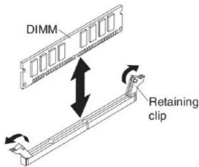
a. Makesure that theretaining clips are in the open position, away from the center of the DIMM connector.
b. TurntheDIMMsothattheDIMMkeysaligncorrectlywiththeDIMM connectoronthesystemboard.
Attention: To avoid breaking theretaining clipsordamaging the DIMM connectors, handle the clips gently.
c. Press the DIMMinto the DIMM connector. Theretaining clips will lock the DIMM into the connector.
d. Makesurethatthesmalltabsontheretainingclipsareinthenotcheson theDIMM. If thereisagapbetweentheDIMM and theretainingclips, the DIMM has not been correctly installed. PresstheDIMM firmly into the connector, and then presstheretainingclipstoward the DIMM until the tabs are fully seated. When the DIMM is correctly installed, theretaining clips are parallel to the sides of the DIMM.
-
If the DIMM accessdoor is open, use your finger to close it.
-
If you have other device to install or remove, do so now; otherwise, goto "Completing the installation" on page 54.
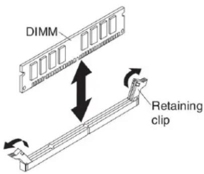
Removingamemorymodule
Usethisinformationtoremoveamemorymodulefromthebladeserver.
The following illustrations show show to remove a DIMM from the bladeserver. This information also applies to removing a DIMM filler.
ToremoveaDIMM, completethefollowingsteps.
-
Before you begin, read "Safety" on page and "Installation guidelines" on page21.
-
If the bladeserver is installed in a Blade Center unit, remove it (see "Removing the bladeserver from the Blade Center unit" on page 23).
-
Removethebladeservercover(see "Removingthebladeservercover" on page 24).
-
If an optionalexpansionunitis installed, remove the expansion unit (see "Removing an optionalexpansion unit" on page 26).
-
LocatetheDIMMconnectors(see "Bladeserverconnectors" onpage19). DeterminewhichDIMMyouwanttoremovefromthebladeserver.
Attention: To avoid breaking theretaining clips or damaging the DIMM connectors, handle the clips gently.
- MovetheretainingclipsontheendsoftheDIMMconnectortotheopen positionbypassingtheretainingclipsawayfromthecenteroftheDIMM connector.
Note: To access DIMM connector seven through twelve, use your finger to lift the DIMM access door.

-
Using your fingers, pull the DIMM out of the connector.
-
InstallaDIMMorDIMMfillerineachemptyDIMMconnector(see "Installing amemorymodule" onpage29).
Note: ADIMMorDIMMfillermustoccupyeachDIMMsocketbeforethe bladeserveristurnedon.
InstallingaGPUadapterintheBladeCenterGPUexpansionunit
UsetheseinstructionstoinstallaGPUadapterintheBladeCenterGPUexpansion unitinstalledonabladeserver.
ToinstallaGPUadapterintheBladeCenterGPUexpansionunit,completethe followingsteps:
-
Before you begin, read "Safety" on page and "Installation guidelines" on page21.
-
If the bladeserver is installed in a BladeCenter unit, remove it (see "Removing the bladeserver from the BladeCenter unit" on page 23 for instructions).
-
If the expansion unit is installed on abladeserveroranother expansion unit, remove it (see "Removing an optionalexpansion unit" on page 26 for instructions).
-
Removethebladeservercover(see "Removingthebladeservercover" on page24 (or instructions)).
-
If an expansion unit is installed over the expansion unit you want to install the adapter in, remove that expansion unit (see "Removing an optional expansion unit" on page 26 for instructions).
-
If you haven total ready doneso, touch the static-protective package that contains the GPU adapter to any unpainted metals surface of the Blade Center unit or any unpainted metals surface on any other grounded rack-component for at least 2 seconds.
-
Removethe GPU adapter from its static-protective package.
-
ConnecttheGPUadaptertothePCIconnectorintheexpansion-unitriser assembly,asshowninthefollowingillustration.

natural_image
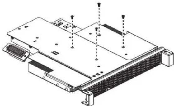
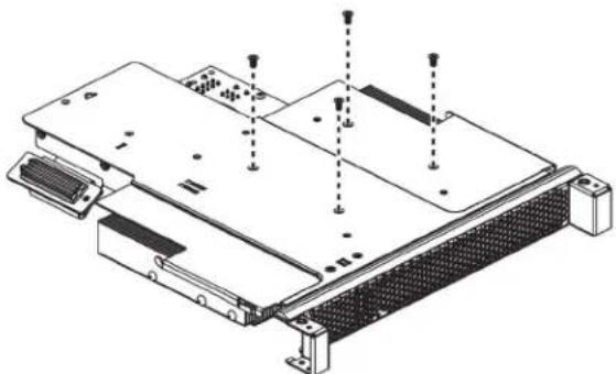
Technical line drawing of an electronic hardware module with cooling fans and heat sinks (no text or symbols)- Carefully turnover the expansion-unit riser assembly, and use a Phillips screw drivertoin install the four non-captiver retainings screws, as shown in the following illustration.
natural_image
Technical line drawing of an electronic device chassis with mounting hardware and screw holes (no text or symbols)- Turnovertheexpansion-unitriserassemblyandinstalltheriserassemblyinto theexpansionunitsystemboard,asshowninthefollowingillustration.
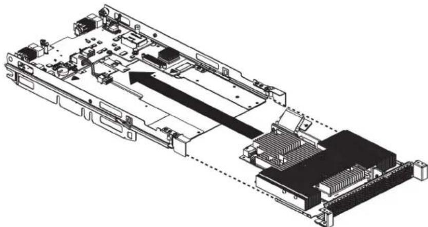
natural_image
Technical line drawing of an electronic circuit board with internal components and a highlighted connection area (no text or symbols)-
Carefully reposition the expansion-unit riser assembly, aligning it with the expansion-unitsystem-board-assembly rails.
-
Firmlyslidetheassembliestogetheruntilthetray-releasebuttonsecurely locksthepanels.
-
Connect the auxiliary powercable (A), asshown in the following illustration.

- Connect the cable to the expansion-unitsystemboard. Replacether retention bracket and tight enthescrews(B), as shown in the illustration above.
If you have other device to install or remove, do so now; otherwise, goto "Completing the installation" on page 54.
RemovingaGPUadapterfromtheBladeCenterGPUexpansionunit
Use this information to remove a GPU adapter from the Blade Center GPU expansion unit.
Notes:
-
The following illustrations show show to remove a GPU adapter from the BladeCenterGPU expansion unit.
-
The illustrations in this document might differs slightly from your hardware.
ToremoveaGPUadapterfromtheBladeCenterGPUexpansionunit,completethe followingsteps:
-
Before you begin, read "Safety" on page and "Installation guidelines" on page21.
-
If the bladeserveris installed in a Blade Center unit, remove it (see "Removing the bladeserver from the Blade Center unit" on page 23 for instructions).
-
Removethebladeservercover(see "Removingthebladeservercover" on page 24 for instructions).
-
If an expansion blade is installed on the expansion blade containing the adapter you want to remove, remove it (see "Removing an option a expansion unit" on page 26.)
-
Removetheexpansion-bladeriserassemblyfromtheBladeCenterGPU expansionblade:
a.Disconnecttheauxiliarypowercable(A)fromtheGPUadapter,asshown inthefollowingillustration.
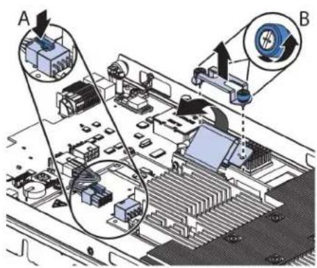
b. Loosenthescrewsandremovetheretentionbracket, thendisconnectthe cablefromtheexpansion-unitsystemboard(B).
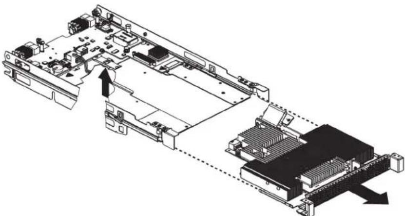
c. Locatethetray-releasebuttononthebottomoftheexpansionunit.

d. Pressinandholdthetray-releasebutton; then, pulltheexpansion-unitriser assemblyoutoftheexpansion-unitsystemboard.
natural_image
Technical diagram of an electronic device showing internal components and a connected chassis (no text or labels)- Carefully turnover the expansion-unit riser assembly, and use a Phillips screw drivertoremovethe four non-captiver retainings screws, as shown in the following illustration. Store the screws in as a felocation.
natural_image
Technical line drawing of an electronic device chassis with mounting hardware and screw holes (no text or symbols)- Carefully turn the expansion-unit triser assembly back over. Unplug the GPU adapter from the PCI connector in theriser assembly and lift it out of theriser assembly.

natural_image
Technical line drawing of an electronic hardware assembly with cooling fans and a rack (no text or symbols)- If you are instructed to return the GPU adapter, follow wall packaging instructions, and use an app packaging materials for shipping that a resupplied to you.
Installingamicroprocessorandheatsink
The following illustrations show show to install a microprocessor and heats in the bladeserver.
Attention:
-
Donotuseanytoolsorsharpobjectstoliftthelockingleveronthe microprocessorsocket.Doingsomightresultinpermanentdamagetothe systemboard.
-
Donottouchthecontactsinthemicroprocessorsocket. Touchingthesecontacts mightresultinpermanentdamagetothesystemboard.
Toinstallamicroprocessorandheatsink,completethefollowingsteps:
1.Before you begin, read "Safety" on page and "Installation guidelines" on page21.
2.Shutdowntheoperatingsystem,turnoffthebladeserver,andremovethe bladeserverfromtheBladeCenterunit.See"Removingthebladeserverfrom theBladeCenterunit"onpage23forinstructions.
-
Carefully lay the bladeserverona flat, static-protectivesurface.
-
Openthebladeservercover(see "Removingthebladeservercover" on page 24 for instructions).
-
If you are installing a microprocessor in the blades server and an MPE unit expansion unit is attached to the blades server, removed the device (see "Removing an optionalexpansion unit" on page 26).
-
Locatemicroprocessorsocket2(see "Bladeserverconnectors" onpage19).
-
Loosenthefourcaptivescrewsthatsecuretheheat-sinkfillerandthen removethefillerfromthemicroprocessorsocket.
-
Openthemicroprocessorsocketreleaseleverandretainer.
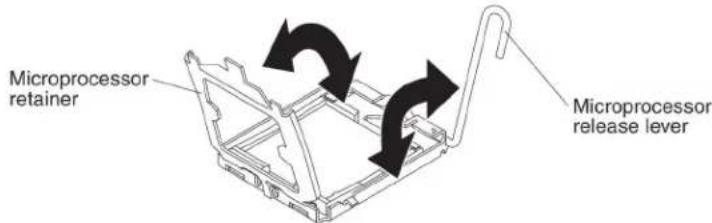
a. Rotatethereleaseleveronthemicroprocessorsocketfromitsclosedand lockedpositionuntilitstopsinthefullyopenposition(approximately a 135°angle).
b. Rotatethemicroprocessorretaineronthemicroprocessorsocketfromits closedpositionuntilstopsinthefullyopenposition(approximately a 135° angle).
-
If dust covers installed over the microprocessor socket, lift the dust cover from the socket and store it in a safe place.
-
Installthemicroprocessorinthemicroprocessorinstallationtool.
a. Removethestatic-protectivebagandthefoamsurroundingthebagfrom thebox.
b. Touch the static-protective bag that contain sthenew microprocesso any unpainted surface on the Blade Center chassis or any unpainted metal surface on any other grounded crack component.
c. Carefully remove themicroprocessor from the static-protective bag, touching only the edges of the microprocessor.
d. If there is a plastic protective cover on the bottom of the microprocessor, carefully remove it.

e.Twistthehandleoftheinstallationtoolcounterclockwisesothatitisinthe openposition.
f. Alignthemicroprocessoralignmentslotswiththealignmentpinsonthe microprocessorinstallationtoolandplacethemicroprocessoronthe undersideofthetoolsothatthetoolcangraspthemicroprocessor correctly.
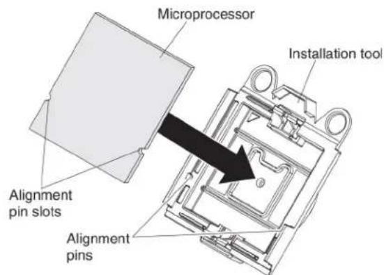
g.Twistthehandleoftheinstallationtoolclockwisetosecurethe microprocessorinthetool.
Note: You can pickup or releasethemicroprocessor by twisting the microprocessor installation tool handle.
- Installthemicroprocessor.
a. Align the installation tool with the microprocessor socket as shown in the following illustration.
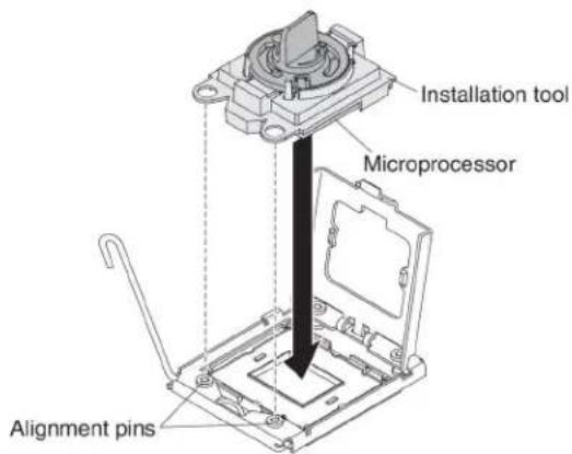
b. Twist the handle on them microprocessortool counterclockwiseto insert the microprocessor into the socket.
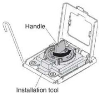
Attention:
- Donotpressthemicroprocessorintothesocket.
- Donottouchexposedpinsofthemicroprocessorsocket.
- Makesurethatthemicroprocessororientedandalignedcorrectlyin thesocketbeforeyoutrytoclosethemicroprocessorretainer.
- Donottouchthethermalmaterialonthebottomoftheheatsinkoron topofthemicroprocessor.Touchingthethermalmaterialwill contaminateit.Ifthethermalmaterialonthemicroprocessororheat sinkbecomescontaminated,contactyourservicetechnician.
c. Carefullyclosethemicroprocessorretainer.
d. Rotatethelockingleveronthemicroprocessorsockettotheclosedand lockedposition.Makesurethattheleverissecuredinthelockedposition bypassingthetabonthemicroprocessorsocket.
- Installaheatsinkonthemicroprocessor.
Attention:
- Donotsetdowntheheatsinkafteryouremovetheplasticcover. - Donottouchthethermalmaterialonthebottomoftheheatsink.Touching thethermalmaterialwillcontaminateit.Ifthethermalmaterialonthe microprocessororheatsinkbecomescontaminated,contactyourservice technician.
a. Removetheplasticprotectivecoverfromthebottomoftheheatsink.
b. Makesure that the thermal material is still on the bottom of the heatsink; then, align and placethe heatsink on top of the microprocessor in the retention bracket, thermal materials sided down. Press firmly on the heat sink.
c. Alignthethreescrewsontheheatsinkwiththeholesontheheat-sink retentionmodule.
d. Press firmly on the captives crews and tight them with a screw driver, alternating among the crews until they are tight. If possible, each screw should be rotated two full rotations at time. Repeat until the crews are tight. Don to overtight the crews by using excessive force. If you are using or que wrench, tight the crew to 8.5 Newton-meters (Nm) to 13 Nm (6.3 foot-pound to 9.6 foot-pounds).
- ReinstallthememorymoduleorDIMMfillerclosesttothemicroprocessor youinstalled.
a. If you installed microprocessor1, install thememory module into DIMM connector1 (see "Installingamemory module" on page 29).
b. If you installed microprocessor2, install thememory module into DIMM connector6 (see "Installingamemory module" on page 29).
-
If you are using a single microprocessor, makes sure that memory modules are installed in DIMM socket2 and DIMM socket6. Iftwomicroprocessors installed in the bladeserver, makes sure that memory modules are installed in DIMM socket2, DIMM socket6, DIMM socket8, and DIMM socket12. See "Installingamemory module" on page 29 form more information on installing amemory module.
-
Installtheoptionalexpansionunit, if you removed one from the bladeserver tore placethe battery (see "Installinganoptionalexpansionunit" on page 25 for instructions).
Thermalgrease
Usethisinformationtodeterminetheguidelinesforusingthermalgreaseona heatsinkandprocessor.
Thethermalgreasemustbereplacedwhenevertheheatsinkhasbeenremoved fromthetopofthemicroprocessorandisgoingtobereusedorwhendebrisis foundinthegrease.
Toreplacedamagedorcontaminatedthermalgreaseonthemicroprocessorand heatsink,completethefollowingsteps:
- Placetheat-sinkassembly on acleanworks surface.
- Removethecleaningpadfromitspackageandunfolditcompletely.
- Use the cleaning pad to wipethethermal grease from the bottom of the heat sink.
Note: Makesurethatallofthethermalgreaseisremoved.
- Use a clean area of the cleaning pad to window the thermal grease from the microprocessor; then, dispose of the cleaning pad after all of the thermal grease is removed.
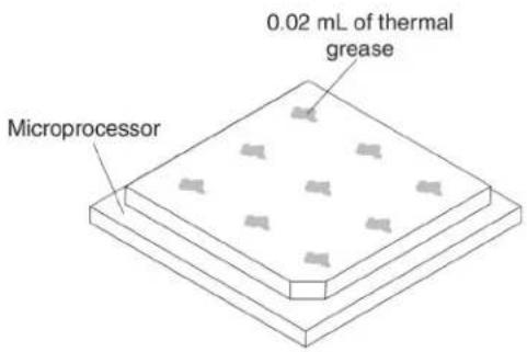
- Use the thermal-greasesyringetoplacenineuniformlyspaceddotsof0.02mL eachonthetopofthemicroprocessor.

Note:0.01mLisonetickmarkonthesyringe.Ifthegreaseisproperlyapplied, approximatelyhalf(0.22mL)ofthegreasewillremaininthesyringe.
6.Continuewithstep11onpage41.
InstallingaUSBFlashkey
UsetheseinstructionstoinstallaUSBFlashkeyinthebladeserver.
The following illustrations show the installation of the USB Flash key.
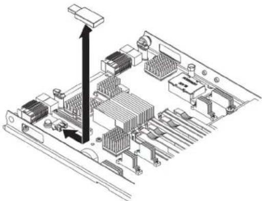
natural_image
Isometric technical diagram of an electronic circuit board with CPU socket and memory components (no text or labels)ToinstallaUSBmodule,completethefollowingsteps:
-
Before you begin, read "Safety" on page and "Installation guidelines" on page21.
-
Readthedocumentation that comes with the DIMMs.
-
If the bladeserverisinstalledinaBladeCenterunit, removeit(see
"RemovingthebladeserverfromtheBladeCenterunit" onpage23for instructions).
-
Carefully lay the blades server on a flat, static-protective surface.
-
Openthebladeservercover(see "Removingthebladeservercover" on page 24 for instructions).
-
If an expansion unit is installed, remove the expansion unit (see "Removing an optionalexpansion unit" on page 26).
-
IfaCIOvexpansioncardisinstalled, removetheexpansioncard(see "RemovingaCIOv-form-factorexpansioncard" onpage48).
-
LocatetheUSBconnectoronthebladeserver(see"Bladeserverconnectors" onpage19).
-
Touch the static-protective package that contains the USB Flash key to any unpainted metal surface on the Blade Center unit or any unpainted metal surface on any other grounded track component in therack in which you are installing the USB module for at least two seconds; then, remove the USB module from its package.
-
OrienttheconnectorontheUSBFlashkeywiththeUSBconnectoronthe bladeserver.
-
Use your finger stop us the USB Flash key into the USB connector on the bladeserver.
-
IfaCIOvexpansioncardwasremovedduringtheinstallprocess,installthe expansioncard(see"InstallingaCIOv-form-factorexpansioncard"onpage 47).
-
If you have other device to install or remove, do so now; otherwise, goto "Completing the installation" on page 54.
I/Oexpansioncards
UsethisinformationtoinstallanI/Oexpansioncard,suchasaSASconnectivity card,inthebladeserver.
The illustrations show installation of the SAS connectivity cardinthesystem board; installing the cardinan expansion unit dissimilar.
ThebladeserverhastwoI/Oexpansionconnectorsonthesystemboard.One connectorsupportshorizontalcombination-form-factor(CFFh)expansioncardsand theotherconnectorsupportsvertical-combination-I/O(CIOv)expansioncards.See http://www.ibm.com/servers/eserver/serverproven/compat/us/foralistof availableI/Oexpansioncardsforyourbladeserver.
MakesurethattheBladeCenterunitandtheI/OmodulestowhichtheI/O expansioncardismappedsupportthenetwork-interfacetypeoftheI/Oexpansion card. Forexample, ifyouaddanEthernetexpansioncardtoabladeserver,the I/OmodulesinI/O-modulebays3and4ontheBladeCenterunitmustbothbe compatiblewiththeexpansioncard.Allotherexpansioncardsthatareinstalled in otherbladeserversintheBladeCenterunitmustalsobecompatiblewiththeseI/O modules.Inthisexample,youcantheninstalltwoEthernetswitchmodules,two pass-thrumodules,oroneEthernetswitchmoduleandonepass-thrumodulein theBladeCenterunit.Becausepass-thrumodulesarecompatiblewithavariety of I/Oexpansioncards,installingtwopass-thrumodulesenablestheuseofseveral typesofcompatibleI/Oexpansioncardsinbladeserverswithinthesame BladeCenterunit.
Installingahorizontal-compact-form-factorexpansioncard
Usetheseinstructionstoinstallacompact-form-factorexpansioncardintheblade server.
The bladeserversupportsahorizontal-combination-form-factor(CFFh)expansion card. The following illustrations show show to install a CFFhexpansion card.
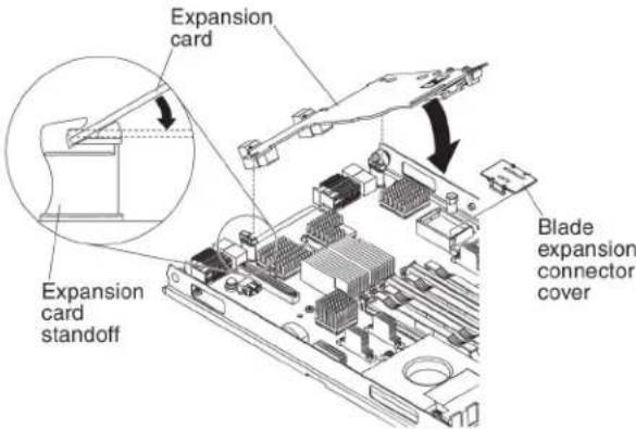
Attention: Before you install one of the following CFF expansion cards in the bladeserver, makes sure the PCIe speedissettoGen1. You can configure the PCIe speed in the Setup utility by selecting System Settings and Devices and I/O Ports.
•2/4PortEthernetExpansionCardforBladeCenter
•Broadcom10Gb2-portEthernetExpansionCard(CFFh)forIBMBladeCenter
•Broadcom10Gb4-portEthernetExpansionCard(CFFh)forIBMBladeCenter
ToinstallaCFFhexansioncard,completethefollowingsteps:
-
Before you begin, read "Safety" on page and "Installation guidelines" on page 21.
-
If the bladeserver is installed in a BladeCenter unit, remove it (see "Removing the bladeserver from the BladeCenter unit" on page 23 for instructions).
-
Carefully lay the bladeserverona flat, static-protectivesurface.
-
Openthebladeservercover(see "Removingthebladeservercover" on page 24 for instructions).
-
Locatethebladeserverexpansionconnector(see "Blade serverconnectors" on page19).
-
Ifacoverisinstalledonthebladeexpansionconnector, removeitbyusing yourfingerstoliftthecoverfromthebladeexpansionconnector.
-
Touch the static-protective package that contains the expansion card to any unpainted metal surface on the Blade Center unit or any unpainted metal surface on any other grounded crack component; then, removes the expansion card from the package.
-
Orienttheexpansioncardandslidetheslotsatthebackendofthecardonto thepinsontheexpansion-cardstandoff;then,gentlypivotthecardintothe bladeserverexpansionconnector.
9.Firmlypressontheindicatedlocationstoseattheexpansioncard.
Note: For device-driver and configuration information to complete the installation of the expansion card, seethedocumentation that comes with the expansion card.
- If you have other device to install or remove, do so now; otherwise, goto "Completing the installation" on page 54.
Removingahorizontal-compact-form-factorexpansioncard
Use these instruction store remove a compact-form-factorexpansioncard from the bladeserver.
The following illustrations show show to remove a horizontal-compact-form-factor (CFFh) expansion card.

ToremoveaCFFhexpansioncard,completethefollowingsteps:
1.Before you begin, read "Safety" on page and "Installation guidelines" on page21.
-
If the bladeserver is installed in a BladeCenter unit, remove it (see "Removing the bladeserver from the BladeCenter unit" on page 23 for instructions).
-
Carefully lay the blades server on a flat, static-protective surface.
-
Openthebladeservercover(see "Removingthebladeservercover" on page 24 for instructions).
-
LocatetheCFFhexansioncard. The CFFhisinstalled into the blade expansion connector (see "Bladeserverconnectors" on page 19).
-
Use your finger to hold the edge of the CFF expansion card where it connects to the blade expansion connector; then, lift upon the card.
-
Pullthecardawayfromtheexpansion-cardstandoff.
InstallingaCIOv-form-factorexpansioncard
UsetheseinstructionstoinstallaCIOv-form-factorexpansioncardintheblade server.
The bladeserversupportsavertical-combination-I/O(CIOv)expansioncardanda horizontal-combination-form-factor(CFFh)expansioncard. The following illustrationsshowsthelocationandinstallationofaCIOvexpansioncard.
Attention: Before you install one of the following CIO expansion cards in the bladeserver, makes sure the PCIe speedissettoGen1. You can configure the PCIe speed in the Setup utility by selecting System Settings and Devices and I/O Ports.
•EthernetExpansionCard(CIOv)forIBMBladeCenter
•QLogic4GbFibreChannelExpansionCard(CIOv)forIBMBladeCenter
•SASConnectivityCard(CIOv)forIBMBladeCenter
•ServeRAID-MR10ie(CIOv)ControllerforIBMBladeCenter
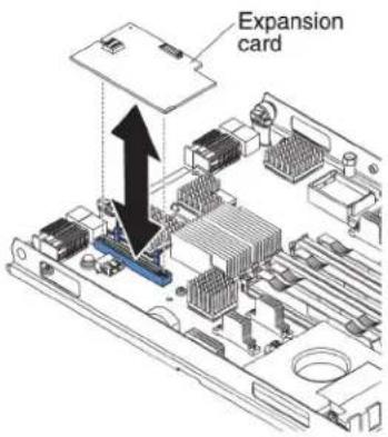
ToinstallaCIOvexpansioncard,completethefollowingsteps:
- Before you begin, read "Safety" on page and "Installation guidelines" on page21.
- If the bladeserver is installed in a BladeCenter unit, remove it (see "Removing the bladeserver from the BladeCenter unit" on page 23 for instructions).
3.Carefullylaythebladeserveronaflat,static-protectivesurface. - Openthebladeservercover(see "Removingthebladeservercover" on page 24 for instructions).
- Touch the static-protective package that contains the expansion card to any unpainted metal surface on the Blade Center unit or any unpainted metal surface on any other grounded rack component; then, removes the expansion card from the package.
- LocatetheCIOvexpansionconnector(see "Bladeserverconnectors" onpage 19).
- OrienttheconnectorontheexpansioncardwiththeCIOvexpansionconnector onthesystemboard;then,pressthecardintotheCIOvexpansionconnector.
8.Firmlypressontheindicatedlocationstoseattheexpansioncard.
Note: For device-driver and configuration information to complete the installation of the expansion card, seethedocumentation that comes with the expansion card.
- If you have other device to install or remove, do so now; otherwise, goto
"Completingtheinstallation" on page 54.
RemovingaCIOv-form-factorexpansioncard
UsetheseinstructionstoremoveaCIOv-form-factorexpansioncardintheblade server.
The following illustrations show show to remove a vertical combination-I/O(CIOv) expansion card.
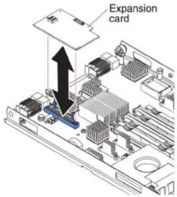
ToremoveaCIOvexpansioncard,completethefollowingsteps:
-
Before you begin, read "Safety" on page and "Installation guidelines" on page 21.
-
If the bladeserver is installed in a BladeCenter unit, remove it (see "Removing the bladeserver from the BladeCenter unit" on page 23 for instructions).
-
Carefully lay the blades server on a flat, static-protective surface.
-
Openthebladeservercover(see "Removingthebladeservercover" on page 24 for instructions).
-
Touch the static-protective package that contains the expansion card to any unpainted metal surface on the Blade Center unit or any unpainted metal surface on any other grounded rack component; then, removes the expansion card from the package.
-
LocatetheCIOvexpansionconnector(see "Bladeserverconnectors" on page 19).
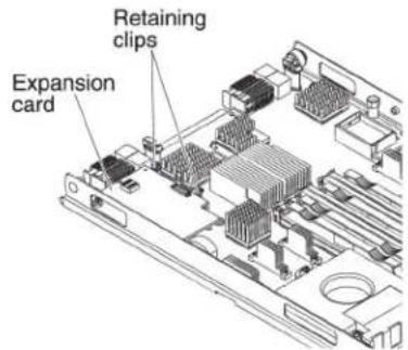
- Using your fingers, mov ether retaining clips away from the CIOvcard; then, lift the card out of the connector.
Installingastorageinterfacecard
Usethisinformationtoinstallastorageinterfacecardinthebladeserver.
The storage interface card control the SAShot-swap storage drives. The following illustrations and installation instruction show show to install a Serve RAID-MR10ie controller into the CIO expansion connector of the blades server. The illustrations and installation instructions are similar for other CIO storage interface cards.
Note:Thebackup-batterywillbeinstalledinDIMMconnectorsevenandmight affecthowmuchmemoryisrecognizedbythebladeserver.Reviewthetablesin "Installingamemorymodule"onpage29tomakesurethatyourmemory configurationwillnotbeaffected.
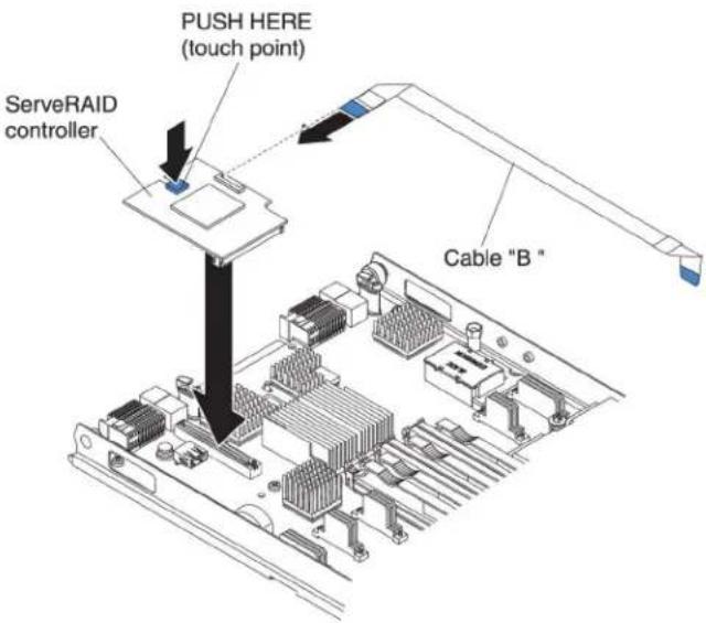
Attention: Before you install a Server RAID-MR10ie controller in the bladeserver, makes sure the PCIe speedissetto Gen 1. You can configure the PCIe speed in the Setup utility by selecting System Settings and Devices and I/O ports.
Toinstallastorageinterfacecard,completethefollowingsteps.
- Before you begin, read "Safety" on page and "Installation guidelines" on page 21.
- If the bladeserver is installed in a BladeCenter unit, remove it (see "Removing the bladeserver from the BladeCenter unit" on page 23 for instructions).
- Removethebladeservercover(see "Removingthebladeservercover" on page24) or instructions).
- If an optionalexpansionunitis installed, removetheexpansionunit(see "Removinganoptionalexpansionunit" on page 26).
-
LocatetheCIOvexpansionconnector(see "Bladeserverconnectors" onpage 19).
-
Touch the static-protective package that contains the storage interface card to any unpainted metal surface on the Blade Center unit or any unpainted metal surface on any other grounded rack component; then, removesthorage interface card from the package.
-
If an interposercard is installed on the storage interface card, remove it.

a. If the interposer has a pull strap, mov the pull strap away from the storage interface card. If the pull straps surround the storage interface card, the pull strap will interfere with the removal of the interposer card.
b. Pressoutontheplasticlatchthatholdstheinterposercardtothestorage interfacecardandsimultaneouslyliftuponthecontroller,asshown.
c.Separatetheinterposercardfromthestorageinterfacecardandstorethe interposercardinasafeplace.
- Install the backup-batterycable to the storage interface card.
a. If you are installing a Server RAID-MR10ie controller, selectable "B" from the packaging.
b. Locatetheendofthecablemarked "EXPANSIONCARD"; then, with the bluesideofthecableendfacingup, carefullyinsertthecableendintothe cableconnectorontheServeRAIDcontroller.
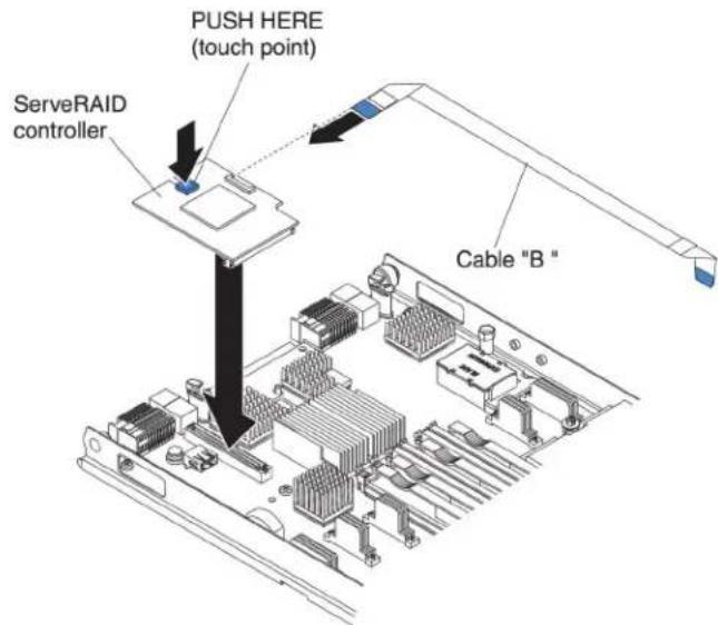
-
Orient the connector on the storage interface card with the CIOvexpansion connector on the system board; then, press the storage interface card into the CIOvexpansion connector.
-
Firmlypressontheindicatedlocationstoseatthestorageinterfacecard.
Note: For device-driver and configuration information to complete the installation of the expansion card, seethedocumentation that comes with the storage interface card.
- InstallthebackupbatteryforthestorageinterfacecardintoDIMMconnector seven(see"Bladeserverconnectors"onpage19and"Installingamemory module"onpage29).
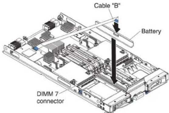
-
Installthebackup-batterycabletothebackupbattery. Thesideofthecable withthebluetouchpointshouldbeorientedtowardsthecenteroftheblade server.
-
Orientthebackup-batterycablesothatitlaysflatoverthetopoftheheatsink formicroprocessortwo.
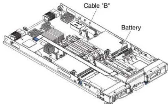
- If you have other device to install or remove, do so now; otherwise, goto "Completing the installation" on page 54.
Removingastorageinterfacecard
Usethisinformationtoremoveastorageinterfacecardfromthebladeserver.
The storage interface card control the SAShot-swap storage drives. The following illustrations and installation instruction show show to remove a Serve RAID-MR10ie CIOv storage interface card from the bladeserver. The illustrations and removal instructions are similar for other CIOv storage interface cards.
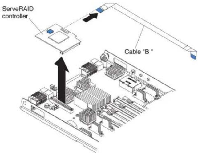
Toremoveastorageinterfacecard,completethefollowingsteps.
1.Before you begin, read "Safety" on page and "Installation guidelines" on page21.
-
If the bladeserver is installed in a BladeCenter unit, remove it (see "Removing the bladeserver from the BladeCenter unit" on page 23 for instructions).
-
Removethebladeservercover(see "Removingthebladeservercover" on page 24 for instructions).
-
If an optionalexpansionunitis installed, removetheexpansionunit(see "Removinganoptionalexpansionunit" on page 26). The storage-interface-card option include the storage interface card, backup battery, and backup battery cable. These part scan beremoved separately from each other.
-
Toremovethestorageinterfacecard, completethefollowingsteps. a. Locatethestorageinterfacecard installed in the CIOvconnector on the systemboard (see "Bladeserverconnectors" on page 19).
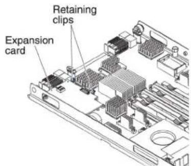
b. Gentlypushtheretainingclipsawayfromtheexpansioncard; then, lift the cardoutoftheexpansion-cardconnector.
c. Removethecablefromthestorageinterfacecardbyholdingthecardinone hand; then, use your other hand top pull the cable away from the card. When pulling the cable, makes sure that you hold the cable where there is a blue touch point.
- Toremovethebackup-batterycable, completethefollowingsteps.
a. Removethecablefromthestorageinterfacecardbyholdingtheblue touchpointonthecable; then, pullthecableawayfromthecard.
b. Removethecable from the backup battery by holding the bluetouch point on the cable; then pull the cable away from the backup battery.
- The backup battery is installed in DIMM connector seven. Toremovethe backup battery, complet the following steps.
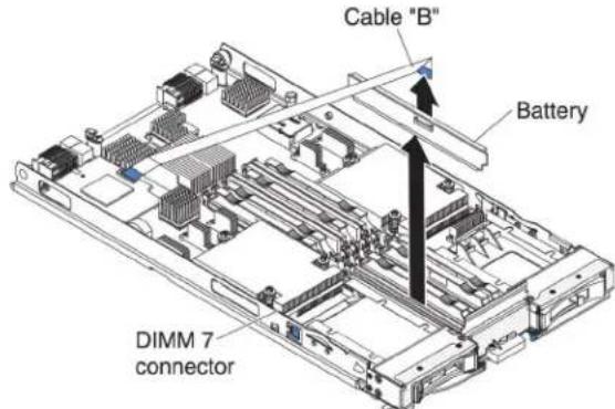
a. If you haven total ready doneso, removethe backup-batterycable from the backup battery by holding the bluetouch point on the cable; then, pull the cable away from the backup battery.
b. RemovethebackupbatteryfromtheDIMMconnectorsevenbyusingthe instructionstoremoveamemorymodule(see"Removingamemory module"onpage33).
8.RemovethebackupbatteryfromDIMMconnectorseven.
Completingtheinstallation
Tocompletetheinstallation,completethefollowingtasks.
-
Reinstalltheoptionalexpansionunit, if you removed on et install other devices (see "nstallinganoptionalexpansionunit" on page 25 for information on installing the expansion unit).
-
Closethebladeservercover, unless you installed an optionale expansion unit that has its own cover (see "Closingthebladeservercover" on page 55).
Statement21

CAUTION:
Hazardousenergyispresentwhenthebladeserverisconnectedtothepower source.Alwaysreplacethebladeservercoverbeforeinstallingtheblade server.
-
ReinstallthebladeserverintotheBladeCenterunit(see "Installingtheblade serverinaBladeCenterunit" onpage56).
-
Turnonthebladeserver(see"Turringonthebladeserver"onpage18). If you have just connected the power cord of the Blade Center unit to electrical outlets, you must wait until the power-on LED on the bladeserver flashes slowly before you press the power-control button.
-
For certain optional devices, you might have to run the blades server setup utility to configure the blades server (see Chapter 4, "Configuring the blade server," on page 59). Seethedocumentation that comes with your optional device for additional information.
Closingthebladeservercover
Usetheseinstructionsforinformationabouthowtoclosethebladeservercover.
Attention: You cannot insert the blades server into the Blade Center unit until the cover is installed and closed for an expansion unit is installed. Donot attempt to override this protection.
Toclosethebladeservercover,completethefollowingsteps:

-
Read the safety information that begins on page "Safety" on page and "Installation guidelines" on page 21.
-
ClosetheDIMMaccessdoorbyrotatingthedoortowardstheDIMM connectors.

-
If you removed an expansion unit from the bladeserver, install it now (see "Installing an optionalexpansion unit" on page 25).
-
Lowerthecoversothattheslotsattherearslidedownontothepinsatthe rearofthebladeserver,asshownintheillustration.Beforeyouclosethecover, makesurethatallcomponentsareinstalledandseatedcorrectlyandthatyou havenotleftloosetoolsorpartsinsidethebladeserver.
-
Pivot the cover to the closed position, as shown in the illustration, until it clicks into place.
InstallingthebladeserverinaBladeCenterunit
UsetheseinstructionstoinstallthebladeserverinaBladeCenterunit.
The following illustrations show show to install abladeserverintoaBladeCenter unit. The appearance of your BladeCenter unit might be different; seethe documentation for your BladeCenter unit for additional information. To install a bladeserverinaBladeCenter unit, complet the following steps.

natural_image
Diagram of a server rack with multiple ports and an open panel, showing internal structure and rotation arrows (no text or symbols)Statement21

CAUTION:
Hazardousenergyispresentwhenthebladeserverisconnectedtothepower source.Alwaysreplacethebladecoverbeforeinstallingthebladeserver.
-
Before you begin, read "Safety" on page and "Installation guidelines" on page21.
-
Selectthebladebayforthebladeserver; atleastonebladebayisrequired.
Notes:
a. When any bladeserveror device is in blade bay 7 through 14, power modules must be installed in all four power module bays. For additional information, se the Installation and User's Guidance that comes with the Blade Center unit.
b. If you are installing abladeserver that you removed, you must install it in the same blade bay from which you removed. Some bladeserver configuration information and update options are established according to bladeserver bay number. Reinstalling abladeserver into a different blade server bay number from the one which it was removed can have unintended consequences, and you might have to configure the blade server.
c. To help ensure proper cooling, performance, and system reliability, make sure that each blade bay on the front of the Blade Center unit contains a bladeserver, expansion unit, or bladefiller. Donot operate a Blade Center unit form more than 1 minute without abladeserver, expansion unit, or bladefillerineach bladebay.
- Makesurethatthereleasehandlesonthebladeserverareintheopen position(perpendicularartothebladeserver).
Attention: Two people are required to install a Type1911 bladeserver into the bay.
Statement4:(forType1911)

≥ 18 kg (39.7 lb)

≥ 32 kg (70.5 lb)

≥ 55 kg (121.2 lb)
CAUTION:
Usesafepracticeswhenlifting.
4.Slidethebladeserverintothebladebayuntilitstops.
- Push therelease handles on the front of the blades, server to the closed position.
Note: Afterthebladeserverisinstalled, theserviceprocessorintheblade serverinitializesandsynchronizeswiththemanagementmodule. Thisprocess takes approximatelytwominutestocomplete. Thepower-onLEDflashes rapidly, and the power-controlbuttononthebladeserverdoesnotrespond until this process is complete.
-
Turnonthebladeserver(see "Turningonthebladeserver" on page 18 for instructions).
-
Makesure that the power-on LED on the bladeserver control panel is lit continuously, indicating that the bladeserver is receiving power and disturbed on.
-
If you have other blades server stoinstall, dosonow.
9.Optional:Writeidentifyinginformationononeofthelabelsthatcomewith thebladeserversandplacethelabelontheBladeCenterunitbezel.Seethe documentationforyourBladeCenterunitforinformationaboutthelabel placement.
Important: Donotplacethelabelonthebladeserverorinanywayblockthe ventilationholesonthebladeserver.
- ReinstallthebezelassemblyontheBladeCenterTunit(BladeCenterTunit only). Fordetailedinstructionsforreinstallingthebezelassembly,seethe InstallationandUser'sGuidethatcomeswiththeBladeCenterTunit.
If this is the initial installation of the bladeserver in the Blade Center unit, you must configure the bladeserver through the Setup utility and install the blade server operating system. See "Updating the bladeserver configuration" on page 58
and Chapter5, "Installingtheoperatingsystem," onpage73fordetails.
If you have changed the configuration of the bladeserver or if you are installing a different bladeserver from the one that you removed, you must configure the bladeserver through the Setuputility, and you might have to install the blade server operating system. For more information, see "Using the Setuputility" on
page60.
Updatingthebladeserverconfiguration
Usethisinformationtoupdatethebladeserverconfiguration.
When the bladeserverstarts for the first time after you add or remove an internal device, you might receive a message that the configuration has changed. The Setup utility automatically starts so that you can save the new configuration settings. See "Using the Setup utility" on page 60 form more information about the Setup utility.
Someoptionshavedevicedriversthatyoumustinstall.Seethedocumentation thatcomeswitheachdeviceforinformationaboutinstallingdevicedrivers.
The bladeserveroperatesas asymmetricmultiprocessing(SMP)server,regardless of how many microprocessors are installed. For optimum performance, you must upgrade the operating system to support SMP. See Chapter 5, "Installing the operating system," on page 73 and your operating-system documentation for additional information.
Input/outputconnectorsanddevices
Usethisinformationtolocatetheinput/outputconnectorsanddevices.
Theinput/outputconnectorsthatareavailabletothebladeserveraresuppliedby theBladeCenterunit.SeethedocumentationthatcomeswiththeBladeCenterunit forinformationabouttheinput/outputconnectors.
The bladeserverhastwoselectionbuttonsonthecontrolpanel:themediatray selectbuttonandthekeyboard/video/mouseselectbutton.See"Bladeserver controlsandLEDs"onpage15forinformationaboutthesebuttonsandtheir functions.
TheEthernetcontrollersthebladeservercommunicatewiththenetwork throughtheEthernet-compatibleI/OmodulesintheBladeCenterunit.Network signalstoandfromthebladeserveroranyexpansioncardsareautomatically routedtoasame-network-interfaceI/Omodulethroughcircuitryinthe BladeCenterunit.
Chapter4.Configuringthebladeserver
Use this information for details about the configuration requirements of the blade server.
Thischapterdescribestheconfigurationrequirementsofthebladeserver.Before youcontinue,makesurethatthebladeserverhasthelatestversionoffirmware code.Foradditionalinformation,see"Firmwareupdates"onpage66.
The following configuration programs comewith the bladeserver:
- Setuputility
TheSetuputilityisusedtochangesystemsettings,suchasinterruptrequests (IRQ),dateandtime,andpassword.See"UsingtheSetuputility"onpage60for moreinformation.
•LSILogicConfigurationUtilityprogram
TheLSILogicConfigurationUtilityprogramisstoredintheblade-server firmware.Useittosetthedevicescanorderandtosetthestoragedrive controllerIDs.See"UsingtheLSILogicConfigurationUtilityprogram"onpage 68formoreinformation.
•IBMFastSetup
IBMFastSetupisano-costsoftwaretoolthathelpssimplifythemaintenanceand deploymentofselectedIBMBladeCenterchassis,servers,andcomponents.The intuitivegraphicalinterfaceinitializesallphasesofserversetup,including discovery,update,andconfiguration.Featuresincludetemplatesthatenable replicationofsettingstomanyserversandautomationthatreduceshands-on timeandusererrors.Wizardsandotherdefaultsettingsenablecustomization capabilities.Thelow-touch,set-onceandwalk-awayfeaturereduceshe hands-onserversetuptimefromdaystominutes,particularlyforlarger deployments.Forinformationaboutthistool,seehttp://www-947.ibm.com/support/entry/portal/docdisplay?lndocid=TOOL-FASTSE].
•IBMServerGuideSetupandInstallationCD
TheServerGuideprogramprovidessoftware-setuptoolsandinstallationtools thataredesignedforthebladeserver.UsethisCDduringtheinstallationofthe bladeservertoconfigurebasichardwarefeaturesandtosimplifytheinstallation oftheoperatingsystem.ForinformationaboutobtainingandusingthisCD,see "UsingtheServerGuideSetupandInstallationCD"onpage63.
•PrebootExecutionEnvironment(PXE)bootagentutilityprogram
The PXEbootagentutilityprogramispartofthebladeserverfirmware.Useit toselectthebootprotocolandotherbootoptionsandtoselecta power-managementoption.Forinformationaboutusingthisutilityprogram,see "UsingthePXEbootagentutilityprogram" onpage66.
TheIBMRemoteDeploymentManager(RDM)Version4.4programisavailablefor purchase.YoucanuseRDMtoinstallaUEFIcodeupdateontoabladeserver.For the latestinformationaboutRDM,includingwhichoperatingsystemsthatRDM supportsandhowtopurchasethesoftware,seechttp://www.ibm.com/systems/management/.
UsingtheSetuputility
UsetheseinstructionstostarttheSetuputility.
TostarttheSetuputility, completethefollowingsteps:
-
Turnonthebladeserver(see "Turningonthebladeserver" on page 18).
-
Immediately givethebladeservercontrol of the Blade Center unit shared keyboard, video, and mouseports.
- If you are managing the bladeserver by using the BladeCentersystem console, press the KVM select button on the bladeserver (see "Bladeserver controls and LEDs" on page 15 for information).
- If you are managing the blade server from a remote location, see the IBM BladeCenterManagementModuleUser'sGuide,IBMBladeCenterManagement Module Command-Line Interface Reference Guide, or IBM BladeCenter Serial over LANSetupGuideforinformationandinstructions.
-
When the prompt
Setup is displayed, press F1. If you have set an administratorpassword,youmustypetheadministratorpasswordtoaccess thefullSetup-utilitymenu.Ifyoudonottypetheadministratorpassword,a limitedSetup-utilitymenuisavailable. -
Follow the instructions on the screen.
Setuputilitymenu
UsetheSetuputilitymainmenutoviewandconfigurebladeserverconfiguration dataandsettings.
The following menu items are on the Setup utility main menu. Depending on the version of the Unified Extensible Firmware Interface (UEFI), some menu items might differ slightly from these descriptions.
•SystemInformation
Selectthischoicetoviewinformationabouttheserver.WhenyoumakechangesthroughotherchoicesintheSetuputility, someofthosechangesarereflectedinthesysteminformation; youcannotchangesettingsdirectlyinthesysteminformation. ThischoiceisonthefullSetuputilitymenuonly.
-SystemSummary
Selectthischoicetoviewconfigurationinformation,includingtheID,speed,andcachesizeofthemicroprocessors,machinetypeandmodeloftheserver,theserialnumber,thesystemUUID,andtheamountofinstalledmemory.WhenyoumakeconfigurationchangesthroughotheroptionsintheSetuputility,thechangesarereflectedinthesystemsummary;youcannotchangesettingsdirectlyinthesystemsummary.
-ProductData
Selectthischoicetoviewthesystem-boardidentifier,therevisionlevelor issuedateofthefirmware,theintegratedmanagementmoduleand diagnosticscode,andtheversionanddate.
ThischoiceisonthefullUEFISetupUtilitymenuonly.
- SystemSettings
Select this choicetovieworchangetheservercomponentsettings.
-Processors
Selectthischoicetovieworchangetheprocessorsettings.
-Memory
Selectthischoicetovieworchangethememorysettings.
-DevicesandI/OPorts
Selectthischoicetovieworchangeassignmentsfordevicesand input/output(I/O)ports.Youcanconfiguretheremoteconsoleredirection, enableordisableintegratedEthernetcontrollers,andtheSAScontroller.If youdisableadevice,itcannotbeconfigured,andtheoperatingsystemwill notbeabletodetectit(thisisequivalenttodisconnectingthedevice).
-Power
Select this choicetovieworchangepowercappingtocontrolpower consumption and processor performance states.
-LegacySupport
Selectthischoicetovieworsetlegacysupport.
Select this choice to force INT video support, if the operating system does not support UEFI video output standards.
-RehookINT
Select this choiceto enable or disable devices from taking control of the bootprocess. The default is Disable.
-LegacyThunkSupport
Select this choiceto enable order disable UEFI to interact with PCI mass storage device that are non-UEFI compliant.
-IntegratedManagementModule
Select this choicetovieworchangethesettingsfortheintegrated managementmodule.
-POSTWatchdogTimer
SelectthischoicetovieworenablethePOSTwatchdogtimer.
-POSTWatchdogTimerValue
SelectthischoicetovieworsetthePOSTloaderwatchdogtimervalue.
-RebootSystemonNMI
Enableordisablerestartingthesystemwheneveranonmaskableinterrupt (NMI)occurs.Disabledisthedefault.
-NetworkConfiguration
Selectthischoicetoviewthesystemmanagementnetworkinterfaceport, theIMMMACaddress, thecurrentIMMIPaddress, andhostname; define thestaticIMMIPaddress, subnetmask, andgatewayaddress, specify whetherousethestaticIPaddressorhaveDHCPassigntheIMMIP address, savethenetworkchanges, andresettheIMM.
-ResetIMMtoDefaults
SelectthischoicetovieworresetIMMtothedefaultsettings.
-SystemSecurity
Selectthischoicetovieworconfiguresecurityoptions.
-AdaptersandUEFIDrivers
Select this choice to view information about the adapters and UEFIdrivers installed in the server.
-Network
Selectthischoicetovieworconfigurethenetworkdeviceoptions,suchas iSCSI,PXE,andBroadcom.
-TrustedPlatformModule(TPM)
SelectthischoicetoviewandconfigureTPMsettings.
- DateandTime
Selectthischoicetosethedateandtimeintheserver,in24-hourformat (hour:minute:second).
ThischoiceisonthefullUEFISetupUtilitymenuonly.
- StartOptions
Selectthischoicetovieworchangethestartoptions,includingthestartup sequence,keyboardNumLockstate,PXEbootoption,andPCIdeviceboot priority.Changesinthestartupoptionstakeeffectwhenyoustarttheserver.
The startup sequences specifiesthe orderin which the server checks device to find a boot record. The server starts from the first boot record that it finds. If the server has Wakeon LAN hardware and software and the operating system supports Wakeon LAN functions, you can specify a startup sequence for the Wakeon LAN functions. For example, you can define a startup sequence that checks for ad disc in the CD-RW/DVD drive, then check the hard disk drive, and then checks an network adapter.
ThischoiceisonthefullUEFISetupUtilitymenuonly.
- BootManager
Selectthischoicetoview,add,delete,orchangethedevicebootpriority,boot fromafile,selectaone-timeboot,orresetthebootordertothedefaultsetting.
- SystemEventLogs
SelectthischoicetoentertheSystemEventManager,whereyoucanviewthe errormessagesinthesystemeventlogs.Youcanusethearrowkeystomove betweenpagesintheerrorlog.
Thesystemeventlogscontainalleventanderrormessagesthathavebeen generatedduringPOST,bythesystems-managementinterfacehandler,andby thesystemserviceprocessor.Runthediagnosticprogramstogetmore informationabouterrorcodesthatoccur.SeetheProblemDeterminationand ServiceGuideforinstructionsonrunningthediagnosticprograms.
Important: If the system-error LED on the front of the server is lit but there are no other error indications, clear the IMM system-event log. Also, after you complete a repair or correct an error, clear the IMM system-event log to turn off the system-error LED on the front of the server.
-POSTEventViewer
SelectthischoicetoenterthePOSTeventviewertoviewthePOSTerror messages.
-IMMSystemEventLog
SelectthischoicetoviewtheIMMsystemeventlog.
-ClearIMMSystemEventLog
SelectthischoicetocleartheIMMsystemeventlog.
-UserSecurity
Selectthischoicetoset,change,orclearpasswords.See"Usingpasswords"on page63formoreinformation.
- SaveSettings
Selectthischoicetosavethechangesthatyouhavemadeinthesettings.
-RestoreSettings
Select this choicetocancel the changest hat you havemade in these settings and restore the previous settings.
- LoadDefaultSettings
Selectthischoicetocancelthechangesthatyouhavemadeinthesettingsand restorethefactorysettings.
- ExitSetup
SelectthischoicetoexitfromtheSetuputility.Ifyouhavenotsavedthe changesthatyouhavemadeinthesettings,youareaskedwhetheryouwantto savethechangesorexitwithoutsavingthem.
Usingpasswords
Usethisinformationtoset,change,ordeleteapower-onpassword.
Youcanset,change,anddeleteapower-onpasswordandanadministrator password in the Setup utility by selecting System Settings then System Security.
If you set a power-on password, you must the power-on password to complete the system startup and to have access to the Setup Utility menu.
Thepasswordmustbefrom6to20characters.YoucanuseanycombinationofASCIIprintablecharactersforthepassword.Keeparecordofyourpasswordinasecureplace.
If you forget the power-on password, you can regain access to the blades server either by removing the bladeserver battery and then reinstalling itor by using the power-on password over overrides with (see the Problem Determination and Service Guide on the Documentation CD for instructions).
Anadministratorpasswordisintendedtobeusedbyasystemadministrator;it limitsaccesstothefullSetuputilitymenu.
Attention: If you set an administrator password and then forget it, there is no way to change, override, or remove it. You must replace the system board.
UsingtheServerGuideSetupandInstallationCD
Use this information as an overview for using the Server Guide Setup and Installation CD.
TheServerGuideSetupandInstallationCDcontainsasetupandinstallationprogram thatisdesignedforyourbladeserver.TheServerGuideprogramdetectstheblade servermodelandoptionalhardwaredevicesthatareinstalledandusesthat informationduringsetuptoconfigurethehardware.TheServerGuideprogram simplifiesoperating-systeminstallationsbyprovidingupdateddevicedriversand, insomecases,installingthemautomatically.
YoucandownloadafreeimageoftheServerGuideSetupandInstallationCDor purchasetheCDfromtheServerGuidefulfillmentWebsiteat http://www.ibm.com/systems/management/serverguide/sub.htm. Todownload thefreeimage,clickIBMServiceandSupportSite.
Note: Changes are made periodically to the IBM Website. The actual procedure might vary slightly from what is in this document.
TheServerGuideprogramperformsthefollowingtasks:
•Aneasy-to-useinterface
- Diskette-freesetupandconfigurationprogramsthatarebasedondetected hardware
- Devicedriversthatareprovidedforthebladeservermodelanddetected hardware
- Operating-systempartitionsizeandfile-systemtypethatareselectableduring setup
ServerGuidefeatures
UsethisinformationtodeterminetheServerGuidefeatures.
FeaturesandfunctionscanvaryslightlywithdifferentversionsoftheServerGuide program.Tolearnmoreabouttheversionthatyouhave,starttheServerGuideSetup andInstallationCDandviewtheonlineoverview.Notallfeaturesaresupportedon allbladeservermodels.
TheServerGuideprogramrequiresasupportedIBMbladeserverthatisassociated withanenabledstartable(bootable)CDdrive.InadditiontotheServerGuideSetup andInstallationCD,youmusthavetheoperating-systemCDtoinstalltheoperating system.
TheServerGuideprogramhasthefollowingfeatures:
- Setssystemdateandtime
- Detectsinstalledoptionalhardwaredevicesandprovidesupdateddevicedrivers formostadaptersanddevices
- Providesdiskette-freeinstallationforsupportedWindowsoperatingsystems
- Includesanonlinereadmefilewithlinkstotipsforthehardwareand operating-systeminstallation
Setupandconfigurationoverview
Usethisinformationtosetupandconfigurethebladeserver.
When you use the Server Guide Setup and Installation CD, you donot needs setup diskettes. You can use the CD to configure any supported IBM bladeserver model. The setup program provides a list of tasks that are required to setup the blade server.
Note: Features and functions can vary slightly with different versions of the ServerGuideprogram.
When you start the Server Guide Setup and Installation CD, the program prompts you to complete the following tasks:
- Selectyourlanguage.
- Selectyourkeyboardlayoutandcountry.
•ViewtheoverviewtolearnaboutServerGuidefeatures. - Viewthereadmefiletoreviewinstallationtipsforyouroperatingsystemand adapter.
- Starttheoperating-systeminstallation.Youwillneedyouroperating-systemCD.
Typicaloperating-systeminstallation
UsethisinformationforatypicalServerGuideoperating-systeminstallation.
TheServerGuideprogramcanreducethetimeittakestoinstallanoperating system.Itprovidesthedevicedriversthatarerequiredforthehardwareandfor theoperatingsystemthatyouareinstalling.Thissectiondescribesatypical ServerGuideoperating-systeminstallation.
Note: Features and functions can vary slightly with different versions of the ServerGuideprogram.
- After you have completed the setup process, the operating-system installation program starts. (You will need your operating-system CD to complete the installation.)
- TheServerGuideprogramstoresinformationaboutthebladeservermodel, serviceprocessor, harddiskdrivecontrollers, and network adapters. Then, the programcheckstheCDfornewerdevicedrivers. This information is stored and then passed to the operating-system installation program.
- The Server Guide program presents operating-system partition option that are based on your operating system selection and the installed hard disk drives.
- TheServerGuideprogrampromptsyoutoinsertyouroperating-systemCD andrestartthebladeserver. At thispoint, the installation program for the operating system takes control to complete the installation. The Blade Center CD drivemustbe associated with the bladeserver when this step is performed.
InstallingtheoperatingsystemwithoutusingServerGuide
Usetheseinstructionstoinstalltheoperatingsystemonthebladeserverwithout usingaServerGuide.
If you have already configured the blades server hardware and you are not using the Server Guide program to install the operating system, complete the following step to download the latest operating system installation instructions from the IBM Website.
Note: Changes are made periodically to the IBM Website. The actual procedure might vary slightly from what is described in this document.
-
Gotohttp://www.ibm.com/support/.
-
UnderSupporttype, selectBladeCenter.
-
Under Popular links, select Operating system installation.
-
Under Choose the system you want instructions for, click BladeCenter HS22.
-
From the Installation list, select your operating system to display the available installationdocuments.
UsingthePXEbootagentutilityprogram
UsetheseinstructiontostartthePXEbootagentutilityprogram.
Use the Preboot Execution Environment (PXE) bootagent utility program to select the boot protocol and other boot options and to select a power management option.
Notes:
- The bladeserverdoesnotsupportRemoteProgramLoad(RPL)selectionfor thebootprotocoloption.
- Enabling PXEmightreducethenumberofoptionalexpansionmodulesthat yourbladeservercanmanage.
TostartthePXEbootagentutilityprogram,completethefollowingsteps:
- Turnontheserver(see "Turningonthebladeserver" onpage18).
- When the Broadcom NetXtreme Boot Agent vX.X.X prompt is displayed, press Ctrl+S.Youhave2seconds(bydefault)topressCtrl+Safterthepromptis displayed.
- Follow the instructions on the screentochangetesetting of these selected items.
Firmwareupdates
Use this information to update the bladeserverthelatest level of UEFI code and firmware updates.
IBMperiodicallymakesUEFIcode,serviceprocessor(IMM)firmware,and diagnosticfirmwareupdatesavailableforthebladeserver.Beforeyouinstallthe bladeserverinaBladeCenterunit,gotohttp://www.ibm.com/systems/support/todownloadthelatestfirmwareforthebladeserver.Installtheupdates,usingthe instructionsthatareincludedwiththedownloadedfiles.
Important: To avoid problems and maintain system performance, always make sure that the UEFI code, service processor (IMM) firmware, and diagnostic firmware levels are consistent for all blades servers within the Blade Center unit.
ConfiguringUEFlcompatibledevices
UsethisinformationtoconfigureUEFIcompatibledevices.
YourIBMBladeCenterHS22Type7870,1936,and1911bladeserverisUEFI compatible.UEFIcompatibleexpansioncardscanbeconfiguredthroughtheSetup utility.ToconfigureaUEFIcompatibleexpansioncard,completethefollowing steps:
Note: Before configuring a UEFI compatible device, it is recommended to update the firmware for your blades server. See "Firmware updates" for information on how to update the firmware for your blades server.
-
RuntheSetuputility(see "UsingtheSetuputility" on page 60).
-
Select System Settings → Adapters and UEFI drivers.
-
SelectPleaserefreshthispagefirstandpressEnter.
-
Select the device driver that you want to configure and press Enter.
- When you have finished changing settings, press Escto exit from the program; select Savetosavethesetting that you have changed.
ConfiguringtheGigabitEthernetcontroller
UsethisinformationtolocatethedevicedriversfortheGigabitEthernetcontroller.
Onedual-portGigabitEthernetcontrollerisintegratedonthebladeserversystem board.Thecontrollerprovidesa1000Mbpsfull-duplexinterfaceforconnectingto oneoftheEthernet-compatibleI/OmodulesinI/O-modulebays1and2,which enablesimultaneous transmission and reception of data on the Ethernet local area network (LAN).The Ethernet controller on the system board is routed to I/O-modulebay1orbay2. The logical link of each Ethernet port to an I/O-module bay is assigned by the operating system.
Youdonothavetosetanyjumpersorconfigurethecontrollerforthebladeserver operating system. However, you must install a device to enable the blade server operating system to address the Ethernet controller. For device drivers and information about configuring the Ethernet controller, complete the following steps.
Note: Changes are made periodically to the IBM Website. The actual procedure might vary slightly from what is described in this document.
- Gotohttp://www.ibm.com/support/.
- Under Select product or service type for support, select BladeCenter.
- Under Popular links, click Software and device drivers.
- From the IBM BladeCenter menu, select BladeCenter HS22.
- From the download categories, click the Networking category.
- Find the device driver for your operating system; then, click on the version numbertogoto the download page for the device driver.
ConfiguringaRAIDarray
UsethisinformationtoconfigureaRAIDarray.
ConfiguringaRAIDarrayappliesonlytoabladeserverinwhichtwoormore storagedrivesareinstalled.
Note: When configuring a RAID array, the storage drives must us these an metype of interface. Forex example, a RAID array can be configured with two SAS storage drives, two SATA stored drives, or two SSD storage drives.
Youcanusetwostoragedrivesinthebladeservertoimplementandmanage RAIDlevel-0(striping)orRAIDlevel-1(mirror)arraysinoperatingsystemsthat arelistedontheServerProvenlistathttp://www.ibm.com/servers/eserver/serverproven/compat/us/.Forthebladeserver,youmustconfiguretheRAIDby usingtheLSIConfigurationUtilityprogram.
If an optional RAID expansion card is installed, you can use it to control all of the storage drive that are installed in the blades server. Seethedocumentation that comes with the expansion card for information on how to configure the RAID array.
Important: You must create the RAID array before you install the operating system onthebladeserver.
YoucanusetheLSILogicConfigurationUtilityprogramtoconfigurethestorage drivesandtheSAScontroller.TostarttheLSILogicConfigurationUtility,see
"UsingtheLSILogicConfigurationUtilityprogram."
UsingtheLSILogicConfigurationUtilityprogram
Use these instruction to start the LSILogicConfigurationUtilityprogram.
YoucanusetheLSILogicConfigurationUtilityprogramtopermthefollowing tasks:
- SettheSASdevicescanorder
- SettheSASIDforthecontroller
•ManagetheSASRAIDconfiguration
TostarttheLSILogicConfigurationUtilityprogram, completethefollowingsteps:
Note: The LSI controller on your bladeserverisa UEFI compatible device and can also be configured through the Setuputility for your bladeserver (see
"ConfiguringUEFIcompatibledevices" on page 66).
- Turnonthebladeserver, and makes sure that the bladeserver is the owner of the keyboard, video, and mouse.
- When the <<
>> promptisdisplayed,pressCtrl+C. - Usethearowkeystoselectthecontrollerfromthelistofadapters; then, press Enter.
- Follow the instructions on the screentochangethesetting of these selected items; then, press Enter. If you select SAS Topology or Advanced Adapter Properties, additional screens are displayed.
UsingLANoverUSBtointerfacetheIMM
TheIMMdoesnotrequireIPMIdevicedriversorUSBdaemonsforin-bandIMM communication.Instead,aLANoverUSBinterfaceenablesin-band communicationstotheIMM;theIMMhardwareonthesystemboardpresentsan internalEthernetNICfromtheIMMtotheoperatingsystem.LANoverUSBis alsocalledthe"USBin-bandinterface"intheIMMWebinterface.
Typically, the IMMIP address for the LAN over USB interface is set to a static address of 169.254.95.118 with as subnet mask of 255.255.0.0. In the event of an IP address collision on the network, the IMM might obtain a different IP address in the 169.254.xxx.xxx range.
Because the IMM might obtain a different IP address for the LAN over USB interface, the IBM Advanced Settings Utility (ASU) and firmware flash utilities, DSA, and the IBMDirector Agent use the Service Location Protocol (SLP) to discover the IMMIP address. These tools perform an SLP multicast discovery on the LAN over USB interface. When they receive a response from the IMM, they obtain the attributes that contain the IP address the IM Misusing for the LAN over USB interface.
PotentialconflictswiththeLANoverUSBinterface
Insomesituations, the IMMLANover USB interface can conflict with certain network configurations, applications, or both.
Forexample,OpenMPIattemptstousealloftheavailablenetworkinterfacesona server.OpenMPIdetectstheIMMLANoverUSBinterfaceandattemptstouseit tocommunicatewithothersystemsinaclusteredenvironment.TheLANover USBinterfaceisaninternalinterface,sothisinterfacedoesnotworkforexternal communicationswithothersystemsinthecluster.
ResolvingconflictswiththeIMMLANoverUSBinterface
Use this information to resolve LAN over USB conflicts with network configurations and applications.
ThereareseveralactionsthatresolveLANoverUSBconflictswithnetwork configurationsandapplications:
- For conflict with Open MPI, configure the application so it does not attempt to use this interface.
- Taketheinterfacedown(runifdown underLinux).
3.Removethedriver(runrmmod underLinux). - Disable the USB bin-band interface on the IMM through whether the IMM Web interface or the AMM Web interface.
Important: If you disable the US Bin-band interface, you cannot perform in-band update of the IMM firmware using the Linux or Windows flash utilities. If the US Bin-band interface is disabled, use the Firmware Update option on the IMM Web interface to update the firmware.
If you disable the USB in-band interface, also disable the watchdog timeout to prevent the server from restarting unexpectedly.
- UsethefollowingstepstodisabletheLANoverUSBinterfacefromtheIMM Webinterface.
a. LogintotheIMMonwhichyouwanttodisabletheUSBdevicedriver interface.
b. In the navigation pane, click System Settings and scroll down to the Miscellaneous area.
c. SelecttheDonotallowcommandsonUSBinterfacecheckboxto disabletheUSBin-bandinterface.Selectingthisoptiondoesnotaffectthe USBremotepresencefunctions(forexample,keyboard,mouse,andmass storage).WhenyoudisabletheUSBin-bandinterface,thein-band systems-managementapplicationsuchastheAdvancedSettingsUtility (ASU)andfirmwareupdatepackageutilitiesmightnotwork.
Note: The ASUworkswithadisabledUSBin-bandinterfaceifanIPMI devicedriverisinstalled.
If you try to systems management applications while the in-band interface is disabled, they might not work.
d.ClickSave.
- Use the following stepstodisable the LANover USB interface from the Advanced Management Module (AMM) Web interface:
a.LogintotheAMMWebinterface.
b. In the navigation pane, click Blade Configuration under the Blade Tasks heading.
c. ScrolldowntotheServiceProcessorLANoverUSBinterfaceareonthe BladeConfigurationwebpage. Thesectionlistsallbladesinthechassis whicharecapableofenablinganddisablingtheLANoverUSBinterface.
d. Select the checkboxes next to the blade or blade that you want to enable or disable.
e. Click the Disable button to disable the LAN over USB interface on the selected blades.
ConfiguringtheLANoverUSBinterfacemanually
TheIMMusingtheLANoverUSBinterfacerequiresoperating-systemdriversand otherconfiguration.ThefirmwareupdatepackageorAdvancedSettingsUtility attempttoperformthesetupautomatically,ifneeded.Iftheautomaticsetupfails orifyouprefertosetuptheLANoverUSBmanually,useoneofthefollowing processes.FormoreinformationaboutLANoverUSBconfigurationondifferent operating systems, see the IBM white paper Transitioning to UEFI and IMM on the IBMwebsite(see"Relateddocumentation"onpage4forinformationonhowto findpublicationsforyourbladeserver).
WindowsIPMldevicedriver
UsethisinformationtoinstalltheMicrosoftIPMIdevicedriver.
TheMicrosoftIPMldevicedriverisnotinstalledbydefaultonMicrosoftWindows Server2003R2operatingsystems.ToinstalltheMicrosoftIPMldevicedriver, completethefollowingsteps:
- From the Windows desktop, click Start → Control Panel→ Add or Remove Programs.
- ClickAdd/RemoveWindowsComponents.
- From the component list, select Management and Monitoring Tools, and then clickDetails.
- SelectHardwareManagement.
- Click Next. The installation wizard opens and guides you through the installation.
Note: The Windows installation disk might be required.
LANoverUSBWindowDriverInstallation
Use this information to install the LANover USB driver for Windows.
When you install Windows, there will be an unknown RNDIS device in the device manager. IBM provides a Windows INF file that identifies this device. The signed version of the INF is included in all of the Windows version so the IMM, UEFI, and DSA update packages. Perform the following step to install ibm_rndis_server_os.inf.
Note: ThesestepsonlyneedtobeperformediftheserverisrunningaWindows operatingsystemandtheibm_rndis_server_os.inf filehasnotbeenpreviously installed. Thefileneedstobeinstalledonlyonce.ItisrequiredbyWindows operatingsystemstodetectandusetheLANoverUSBfunctionality.
-
Obtain a Windows version of the IMM, server firmware, and DSA update package (see "Firmware updates" on page 66 form more information).
-
Extract the ibm_rndis_server_os.inf and device.cat files from the firmware updatepackageandcopythemtothe\WINDOWS\inf subdirectory.
-
For Windows 2003: Install the ibm_rndis_server_os.inf file by right-clicking onthefileandselectingInstall.ThisgeneratesaPNFfileofthesamenamein\WINDOWS\inf.
ForWindows2008:GotoComputerManagement,thenDeviceManagerand findtheRNDISDevice.SelectProperties>Driver>Reinstalldriver.Point theservertothe\Windows\inf directorywhereitcanfindthe ibm_rndis_server_os.inf fileandinstallthedevice.
-
Go to Computer Management then Device Manager and right-click on NetworkadaptersandselectScanforhardwarechanges.Asmallpop-up confirmsthattheEthernetdeviceisfoundandinstalled.TheNewHardware Wizardstartsautomatically.
-
When you are prompted with the question, "Can Windows connect to Windows Update to search for software?", select No, not this time. Click Next to continue.
-
When you are prompted with the question, "What do you want the wizard to do?", select Install from a list or specific location (Advanced). Click Next to continue.
-
When you are prompted with the statement, "Please choose your search and installation options", select Don't search. I will choose the driver to install. Click Next to continue.
-
When you are prompted with the statement, "Selectahardwaretype, and then click Next", select Network adapters. Click Next to continue.
-
You are prompted with the statement, "Completing the Found New Hardware Wizard". ClickFinish.
Note: A new local area connection appears and might state, "This connection has limitedornoconnectivity". Ignore this message.
-
GobacktotheDeviceManager.IBMUSBRemoteNDISNetworkDevice appearsunderNetworkAdapters.
-
Open a command prompt, type ipconfig, and press Enter. The local area connectionfortheIBMUSBRNDISappearswithanIPaddressintherangeof 169.254.xxx.xxxwithasubnetmasksetto255.255.0.0.
LANoverUSBLinuxDriverInstallation
UsethisinformationtoinstalltheLANoverUSBdriverforLinux.
CurrentversionsofLinux,suchasRHEL5Update2andSLES10ServicePack2, supporttheLANoverUSBinterfacebydefault.Thisinterfaceisdetectedand displayedduringtheinstallationoftheseoperatingsystems.Whenyouconfigure thedevice,useastaticIPaddressof169.254.95.130withasubnetmaskof 255.255.0.0.
Note:OlderLinux distributions might not detect the LAN over USB interface, and might require manual configuration. For information about configuring LAN over USB specific Linux distributions, seethe IBM white paper Transitioning to UEFI and IMMonth the IBM website (see "Related documentation" on page 4 for information on how to find publications for your bladeserver).
The IMM LAN over USB interface requires that the usbnet and cdc_ether drivers beloaded. If the drivers havenot been installed, use modprobe to install them. When these drivers are loaded, the IMMUSB network interfaces shows supasa
networkdeviceintheoperatingsystem.Todiscoverthenamethatheoperating systemhasassignedtotheIMMUSBnetworkinterface,type:
dmesg | grep -i cdc ether
The interface is configured with if config to have an IP address in the range 169.254.xxx.xxx. Forexample:
ifconfig IMM_device_name 169.254.1.102 netmask 255.255.0.0
ThisinterfaceisconfiguredtocomeupwithanIPaddressinthe169.254.xxx.xxx rangeeachtimethattheoperatingsystemisbooted.
Chapter5.Installingtheoperatingsystem
Usetheseinstructionstoinstalltheoperatingsystemonthebladeserver.
Toinstalltheoperatingsystemonabladeserver,youcanuseanyofthefollowing methods:
- Use the ServerGuide Setup and Installation CD to install a supported Microsoft Windowsoperatingsystem.
- UseRemoteDeploymentManager(RDM)Version4.20(orlater)toinstalla supportedoperatingsystem.TodeterminewhetherRDMsupportsanoperating system,seehttp://www.ibm.com/systems/management/.
- Download the latest operating-system installation instructions and install the operating system.
Important: The operating system in the bladeserver must provide USB support for the bladeserver vertorecognize and usethe keyboard, mouse, and removable-media drives. The Blade Center unit uses USB for internal communication with these devices.
UsingtheServerGuideSetupandInstallationCDtoinstalltheoperatingsystem
UsetheseinstructionsforusingtheServerGuideSetupandInstallationCDto installthebladeserveroperatingsystem.
TousetheServerGuideSetupandInstallationCD, completethefollowingsteps:
- While the bladeserverison, press the KVM select button on the front of the bladeserver to associate the Blade Center unit CD drivewith the bladeserver.
- InserttheCD, and restart the bladeserver. If the CD does not start, see "ServerGuideproblems" on page 76.
- Follow the instructions on the screent to complete the following tasks:
a. Select your language.
b. Select your keyboard layout and country.
c.ViewtheoverviewtolearnaboutServerGuidefeatures.
d.Viewthereadmefiletoreviewinstallationtipsaboutyouoperatingsystem andadapter.
e.Startthesetupandhardwareconfigurationprograms.
f.Starttheoperating-systeminstallation.Youwillneedyouoperating-system CD.
UsingRDMtoinstalltheoperatingsystem
Use this information if you are using RDM to install the bladeserveroperating system.
YoucanuseRDMtoinstallasupportedoperatingsystemonabladeserver.
Follow the instructions in the documentation that comes with RDM to install a supported operating system.
Note: TodeterminewhetheranRDMsupportsanoperatingsystem, see http://www.ibm.com/systems/management/.
Downloadinginstallationinstructions
Usetheseinstructionstodownloadtheoperating-systeminstallationinstructions.
Todownloadoperating-systeminstallationinstructions,completethefollowing steps.
Note: Changes are made periodically to the IBM Website. The actual procedure might vary slightly from what is described in this document.
- Gotohttp://www.ibm.com/systems/support/.
- Under Select product or service type for support, click BladeCenter.
- Under Popular Links, click Operating system installation.
- Under Choose the system you want instructions for, click BladeCenter HS22.
- Under the Installation, select the operating system you want to install.
Chapter6.Solvingproblems
Usetheseinstructionstoresolveanyproblemsyoumayencounterwhileinstalling thebladeserver.
If you install the bladeserver in the Blade Center unit and the bladeserver does not start, perform the following actions:
- MakesurethattheBladeCenterunitiscorrectlyconnectedtoapowersource.
- ReseatthebladeserverintheBladeCenterunit(see "InstallingthebladeserverinaBladeCenterunit" onpage56).
- If the power-on LED is flashings slowly, turn on the bladeserver (see "Turning on the bladeserver" on page 18).
- If you have just added anew optional device or component, makes sure that it is correctly installed and compatible with the bladeserver and its components. If the device or component is not compatible, remove it from the bladeserver, reinstall the bladeserver in the BladeCenterunit, and then restart the blade server.
Ifthebladeserverdoesnotstartafteryouhaveperformedtheprecedingactions, seetheProblemDeterminationandServiceGuideforyourbladeserverontheIBM DocumentationCD.
Diagnostictoolsoverview
Usethisoverviewtolocatespecificdiagnostictoolstodiagnoseandsolvehardware-relatedproblems.
The following tools are available to help you diagnose and solve hardware-related problems:
- POSTcodes, errormessages, and errorlogs
ThePOSTerrorcodesindicate the detection of a problem. Seethe Problem Determination and Service Guide form more information.
- Troubleshootingtables
Thesetableslistproblemsymptomsandactionstocorrecttheproblems.Seethe ProblemDeterminationandServiceGuideforyourbladeserver.
•Lightpathdiagnostics
UselightpathdiagnosticsLEDsonthesystemboardtodiagnosesystemerrors. Ifthesystem-errorLEDonthesystemLEDpanelonthefrontorrearofthe BladeCenterunitislit,oneormoreerrorLEDsontheBladeCenterunit componentsalsomightbelit.TheseLEDshelpidentifythecauseofthe problem.BladeservererrorLEDsaredescribedintheProblemDeterminationand ServiceGuideforyourbladeserver.
•DynamicSystemAnalysis(DSA)InstallableandPortableEditiondiagnostic program
DSAteststhemajorcomponentsoftheBladeCenterunit,includingthe managementmodules,I/Omodules,removable-mediadrives,andtheblade servers,whiletheoperatingsystemisrunning.DSAcanbepluggedintoan existingIBMDirectorenvironmentorinstalledwithoutIBMDirectorpresent. FordocumentationanddownloadinformationforDSA,see
http://www.ibm.com/systems/management/.Formoreinformationabout diagnosticprogramsanderrormessages,seetheProblemDeterminationandServiceGuideforyourbladeserver.
Note: If you are unable to find the system-error logs in the blades server firmware code, view the system-event login in the Blade Center management module.
•DynamicSystemAnalysis(DSA)Prebootdiagnosticprogram
TheDSAPrebootdiagnosticprogramsarestoredinread-onlymemoryand collectandanalyzesysteminformationtoaidindiagnosingserverproblems. Thediagnosticprogramscollectthefollowinginformationabouttheserver:
-Drivehealthinformation
-Lightpathdiagnosticsstatus
-LSIRAIDandcontrollerconfiguration
-Networkinterfacesandsettings
-ServeRAIDconfiguration
-Serviceprocessorstatusandconfiguration
-Systemconfiguration
-EventlogsforServeRAIDcontrollersandserviceprocessors
-Hardwareinventory, including PCI and USB information
-Vitalproductdata,firmware,andUnifiedExtensibleFirmwareInterface (UEFI)configuration
Thediagnosticprogramscreateamergedlogthatincludeseventsfromall collectedlogs.TheinformationiscollectedintoafilethatyoucansendtoIBM serviceandsupport.Additionally,youcanviewtheinformationlocallythrough ageneratedtextreportfile.Youcanalsocopythelogtoremovablemediaand viewthelogfromaWebbrowser.
ServerGuideproblems
UsethisinformationtolocateServerGuideproblemsandsuggestedactions.
The following table lists problems symptoms and suggested solutions.
| SymptomSuggestedaction | |
| TheServerGuideSetupand InstallationCDwillnotstart. | •MakesurethattheCDdriveisassociatedwiththebladeserverthatyouare configuring.•MakesurethatthebladeserversupportstheServerGuideprogramandhasa bootableCD(orDVD)drive.•Ifthestartup(boot)sequencesettingshavebeenchanged,makesurethatthe CDdriveisfirstinthestartupsequence. |
| TheRAIDconfiguration programcannotviewall installeddrives,orthe operatingsystemcannotbe installed. | •MakesurethattherearenoduplicateSCSI/SASIDsorinterruptrequest(IRQ) assignments.See“ConfiguringaRAIDarray”onpage67.•Makesurethatthestoragedriveisconnectedcorrectly.See“Bladeserver connectors”onpage19to ocatethestoragedriveconnector. |
| Theoperating-system installationprogram continuouslyloops. | Makemorespaceavailableontheharddisk. |
| TheServerGuideprogramwill notstarttheoperating-system CD. | Makesurethattheoperating-systemCDissupportedbytheServerGuide program.SeetheServerGuideSetupandInstallationCDlabelforalistofsupported operating-systemversions. |
| Theoperatingsystemcannotbe installed;theoptionisnot available. | Makesurethattheoperatingsystemissupportedonthebladeserver.Ifthe operatingsystemissupported,eithernologicaldriveisdefined(SCSI/SASRAID systems)ortheServerGuideSystemPartitionisnotpresent.RuntheServerGuide programandmakesurethatsetupiscomplete. |
Appendix.Gettinghelpandtechnicalassistance
If you need help, service, or technical assistance or just want more information about IBM products, you will find a wide variety of sources available from IBM to assist you.
UsethisinformationtoobtainadditionalinformationaboutIBMandIBM products,determinewhattodoifyouexperienceaproblemwithyourIBMsystem oroptionaldevice,anddeterminewhomtocallforservice,ifitisnecessary.
Beforeyoucall
Beforeyoucall, makesurethatyouhavetakenthesestepstotrytosolvethe problemyourself.
If you believe that you require IBM to perform warranty service on your IBM product, the IBM servicetechnicians will be able to assist you more efficiently if you prepare before you call.
- Checkallcablestomakesurethattheyareconnected.
- Checkthepowerswitchestomakesurethatthesystemandanyoptional devicesareturnedon.
- Checkforupdatedsoftware,firmware,andoperating-systemdevicedriversfor yourIBMproduct.TheIBMWarrantytermsandconditionsstatethatyou,the owneroftheIBMproduct,areresponsibleformaintainingandupdatingall softwareandfirmwarefortheproduct(unlessitiscoveredbyanadditional maintenancecontract).YourIBMservicetechnicianwillrequestthatyou upgradeyoursoftwareandfirmwareiftheproblemhasadocumentedsolution withinasoftwareupgrade.
- If you have installed new hardware or software in your environment, check http://www.ibm.com/servers/eserver/serverproven/compat/us/eserver.htm to make sure that the hardware and software is supported by your IBM product.
•Gotohttp://www.ibm.com/systems/support/tocheckforinformationtohelpyousolvetheproblem.
•Gather the following information to provide to IBMSupport. This data will help IBMSupport quickly provide as solution to your problemandensure that you receive the level of service for which you might have contracted.
-HardwareandSoftwareMaintenanceagreementcontractnumbers,if applicable
-Machinetypenumber(IBM4-digitmachineidentifier)
-Modelnumber
-Serialnumber
-CurrentsystemUEFIandfirmwarelevels
-Otherpertinentinformationsuchaserormessagesandlogs
•Gotohttp://www.ibm.com/support/electronic/portal/tosubmitanElectronicServiceRequest.SubmittinganElectronicServiceRequestwillstarttheprocessofdeterminingasolutiontoyourproblembymakingthepertinentinformationavailabletoIBMSupportquicklyandefficiently.IBMservicetechnicianscanstartworkingonyoursolutionassoonasyouhavecompletedandsubmittedanElectronicServiceRequest.
Youcansolvemanyproblemswithoutoutsideassistancebyfollowingthe troubleshootingprocedurethatIBMprovidesintheonlinehelperinthe documentationthatisprovidedwithyourIBMproduct. Thedocumentationthat comeswithIBMsystemsalsodescribesthediagnosticteststhatyoucanperform. Mostsystems,operatingsystems,andprogramscomewithdocumentationthat containstroubleshootingproceduresandexplanationsoferrormessagesanderror codes.Ifyoususpectasoftwareproblem,seethedocumentationfortheoperating systemorprogram.
Usingthedocumentation
InformationaboutyourIBMsystemandpreinstalledsoftware,ifany,oroptional deviceisavailableinthedocumentationthatcomeswiththeproduct.That documentationcanincludeprinteddocuments,onlinedocuments,readmefiles, andhelpfiles.
Seethetroubleshootinginformationinoursystemdocumentationforinstructions forusingthediagnosticprograms. Thetroubleshootinginformationorthe diagnosticprogramsmighttellyouthatyouneedadditionalorupdateddevice driversorothersoftware.IBMmaintainspagesontheWorldWideWebwhereyou cangetthelatesttechnicalinformationanddownloaddevicedriversandupdates. Toaccessthesepages,gotohttp://www.ibm.com/systems/support/.
GettinghelpandinformationfromtheWorldWideWeb
Up-to-date information about IBM products and support is available on the World WideWeb.
OntheWorldWideWeb, up-to-date information about IBM systems, optional devices, services, and support is available at http://www.ibm.com/systems/support/.IBM Systemxinformationisat http://www.ibm.com/systems/x/.IBM Blade Center informationisat http://www.ibm.com/systems/bladecenter.IBM IntelliStation informationisat http://www.ibm.com/systems/bladecenter/.
HowtosendDSAdatatoIBM
UsetheIBMEnhancedCustomerDataRepositorytosenddiagnosticdatatoIBM.
BeforeyousenddiagnosticdatatoIBM,readhttp://www.ibm.com/de/support/ecurep/send_http.htm.
YoucanuseanyofthefollowingmethodstosenddiagnosticdatatoIBM:
- Standardupload:http://www.ibm.com/de/support/ecurep/send_http.html
- Standard upload with the system serial number: http://www.ecurep.ibm.com/app/upload_hw/
- Secureupload:http://www.ibm.com/de/support/ecurep/send_http.html#secure
- Secure upload with the system serial number: https://www.ecurep.ibm.com/app/upload_hw/
Creatingapersonalizedsupportwebpage
YoucancreateapersonalizedsupportwebpagebyidentifyingIBMproductsthat areofinteresttoyou.
Tocreateapersonalizedsupportwebpage, gotohttp://www.ibm.com/support/mysupport/.Fromthispersonalizedpage,youcansubscribetoweeklyemail notificationsaboutnewtechnicaldocuments,searchforinformationand downloads,andaccessvariousadministrativeservices.
Softwareserviceandsupport
ThroughIBMSupportLine,youcangettelephoneassistance,forafee,withusage,configuration,andsoftwareproblemswithyourIBMproducts.
ForinformationaboutwhichproductsaresupportedbySupportLineinyourcountryorregion,seehttp://www.ibm.com/services/sl/products/.
FormoreinformationaboutSupportLineandotherIBMservices,see http://www.ibm.com/services/us/index.wssorseehttp://www.ibm.com/planetwide/forsupporttelephonenumbers.IntheU.S.andCanada,call 1-800-IBM-SERV(1-800-426-7378).
Hardwareserviceandsupport
You can receive hardwareservicethrough your IBMreseller or IBMServices.
TolocatearesellerauthorizedbyIBMtoprovidewarrantyservice,goto http://www.ibm.com/partnerworld/andclickFindBusinessPartnersonthe rightsideofthepage.ForIBMsupporttelephonenumbers,see http://www.ibm.com/planetwide/.IntheU.S.andCanada,call1-800-IBM-SERV (1-800-426-7378).
IntheU.S.andCanada,hardwareserviceandsupportisavailable24hoursaday,7daysaweek.IntheU.K.,theseservicesareavailableMondaythroughFriday,from9a.m.to6p.m.
IBMTaiwanproductservice
Use this information to contact IBMTaiwan product service.
IBMTaiwanproductservicecontactinformation:
IBMTaiwanCorporation 3F,No7,SongRenRd. Taipei,Taiwan Telephone:0800-016-888
Notices
This information was developed for products and services offered in the U.S.A.
IBMmaynotoffertheproducts, services, or features discussed in this document in other countries. Consult your local IBM representative for information on the products and services currently available in your area. Any reference to an IBM product, program, or service is not intended to state or imply that only that IBM product, program, or servicem maybe used. Any functionally equivalent product, program, or servicethat does not infringe any IBM intellectual property right may be used instead. However, it is the user's responsibility to evaluate and verify the operation of any non-IBM product, program, or service.
IBMmayhavepatentsorpendingpatentapplicationscoveringsubjectmatter describedinthisdocument. The furnishingofthisdocumentdoesnotgiveyou anylicensetothesepatents. Youcansendlicenseinquiries, inwriting, to:
IBMDirectorofLicensing
IBMCorporation
NorthCastleDrive
Armonk,NY10504-1785
U.S.A.
INTERNATIONAL BUSINESSMACHINESCORPORATIONPROVIDESTHIS PUBLICATION"ASIS"WITHOUTWARRANTYOFANYKIND,EITHER EXPRESSORIMPLIED,INCLUDING,BUTNOTLIMITEDTO,THEIMPLIED WARRANTIESOFNON-INFRINGEMENT,MERCHANTABILITYORFITNESS FORAPARTICULARPURPOSE.Somestatesdonotallowdisclaimerofexpressor impliedwarrantiesincertaintransactions,therefore,thisstatementmaynotapply toyou.
This information could include technical inaccuracies in typographical errors. Changes are periodically made to the information herein; these changes will be incorporated in new editions of the publication. IBM may make improvements and/or changes in the product(s) and/or the program(s) described in this publication at any time without notice.
Anyreferencesinthisinformationtonon-IBMwebsitesareprovidedfor convenienceonlyanddonotinanymannerserveasanendorsementofthose websites.ThematerialsatthosewebsitesarenotpartofthematerialsforthisIBM product,anduseofthosewebsitesisatyourownrisk.
IBMmayuseordistributeanyoftheinformationyousupplyinanywayit believesappropriatewithoutincurringanyobligationtoyou.
Trademarks
IBM, the IBM logo, and ibm.com are trademark sof International Business Machines Corp., registered in many jurisdictions worldwide. Other product and servicenames might be trademark sof IBM or other companies.
AcurrentlistofIBMtrademarksisavailableonthewebat"Copyrightand trademarkinformation athttp://www.ibm.com/legal/copytrade.shtml.
AdobeandPostScriptareeitherregisteredtrademarksorttrademarksofAdobe SystemsIncorporatedintheUnitedStatesand/orothercountries.
CellBroadbandEngineisattrademarkofSonyComputerEntertainment,Inc.,in theUnitedStates,othercountries,orbothandisusedunderlicensetherefrom.
Intel, Intel Xeon, Itanium, and Pentium are trademarks or registered trademark of Intel Corporation or its subsidiaries in the United States and other countries.
JavaandallJava-basedtrademarksandlogosaretrademarksorregistered trademarksofOracleand/oritsaffiliates.
LinuxisaregisteredtrademarkofLinusTorvaldsintheUnitedStates,other countries,orboth.
Microsoft, Windows, and Windows NTaretrademarksof Microsoft Corporation in the United States, other countries, or both.
UNIXisaregisteredtrademarkofTheOpenGroupintheUnitedStatesandother countries.
Importantnotes
Processorspeedindicates the internalclockspeed of the microprocessor; other factors also affect application performance.
CDorDVDdrivespeedisthevariablereadrate. Actualspeedsvaryandareoften lessthanthepossiblemaximum.
Whenreferringtoprocessorstorage,realandvirtualstorage,orchannelvolume, KBstandsfor1024bytes,MBstandsfor1,048,576bytes,andGBstandsfor 1,073,741,824bytes.
Whenreferringtoharddiskdrivecapacityorcommunicationsvolume,MBstands for1,000,000bytes,andGBstandsfor1,000,000,000bytes.Totaluser-accessible capacitycanvarydependingonoperatingenvironments.
Maximuminternalharddiskdrivecapacitiesassumethereplacementofany standardharddiskdrivesandpopulationofallharddiskdrivebayswiththe largestcurrentlysupporteddrivesthatareavailablefromIBM.
Maximummemorymightrequirereplacementofthestandardmemorywithan optionalmemorymodule.
Each solid-state memory cell has an intrinsic, finit number of write cycle that the cell can incur. Therefore, asolid-stated device has a maximum number of write cycle that can be subjected to, expressed as "total bytes written" (TBW). A device that has exceeded this limit might fail to respond to system-generated commands might be incapable of being written to. IBM is not responsible for replacement of device that has exceeded its maximum guaranteed number of program/erase cycles, as documented in the Official Published Specifications for the device.
IBMmakesnorepresentationorwarrantiesregardingnon-IBMproductsandservicesthatareServerProven,includingbutnotlimitedtotheimpliedwartanciesofmerchantabilityandfitnessforaparticularpurpose.Theseproductsareofferedandwarrantedsolelybythirdparties.
IBMmakesnorepresentationsorwarrantieswithrespecttonon-IBMproducts. Support(ifany)forthenon-IBMproductsisprovidedbythethirdparty,notIBM.
Somesoftwaremightdifferfromitsretailversion(ifavailable)andmightnot includeusermanualsorallprogramfunctionality.
Particulatecontamination
Attention: Airborneparticulates(includingmetallakesorparticles)and reactive gasesactingaloneorincombinationwithotherenvironmentalfactorssuchas humidityortemperaturemightposearisktothedevicethatisdescribedinthis document.
Risksthatareposedbythepresenceofexcessiveparticulatelevelsor concentrationsofharmfulgasesincludedamagethatmightcausethedeviceto malfunctionorceasefunctioningaltogether. This specificationsetsforthlimitsfor particulatesandgasesthatareintendedtoavoidsuchdamage. Thelimitsmustnot beviewedorusedasdefinitivelimits, because numerousotherfactors, such as temperatureormoisturecontentoftheair, caninfluencetheimpactofparticulates orenvironmentalcorrosivesandgaseouscontaminanttransfer. In the absence of specific limitsthataretforthinthisdocument, you must implement practices that maintain particulate and gas levelsthatareconsistent with the protection of humanhealthandsafety. If IBM determines that the level of particulatesorgases in you environment have caused damage to the device, IBM may condition provision of repair or replacement of devices or partson implementation of appropriateremedial measure to mitigate such environmental contamination. Implementation of such remedial measures is a customer responsibility.
Table9. Limits for particulates and gases
| ContaminantLimits | |
| Particulate | Theroomairmustbecontinuouslyfilteredwith40%atmospheric dustspotefficiency(MERV9)accordingtoASHRAEStandard52.21.Airthatentersadatacentermustbefilterdto99.97%efficiencyor greater,usinghigh-efficiencyparticulateair(HEPA)filtersthatmeet MIL-STD-282.Thedeliquescentrelativehumidityoftheparticulatecontamination mustbemorethan60%2.Theroommustbefreeofconductivecontaminationsuchaszinc whiskers. |
| Gaseous | Copper:ClassG1asperANSI/ISA71.04-19853Silver:Corrosionrateoflessthan300Åin30days |
| 1.ASHRAE52.2-2008-MethodofTestingGeneralVentilationAir-CleaningDevicesfor RemovalEfficiencybyParticleSize.Atlanta:AmericanSocietyofHeating,Refrigerating and Air-ConditioningEngineers,Inc.Thedeliquescentrelativehumidityofparticulatecontaminationistherelativehumidity atwhichthedustabsorbsenoughwatertobecomewetandpromoteionicconduction.ANSI/ISA-71.04-1985.Environmentalconditionsforprocessmeasurementandcontrol systems:Airbornecontaminants.InstrumentSocietyofAmerica,ResearchTrianglePark, NorthCarolina,U.S.A. | |
Documentationformat
The publications forth this product are in Adobe Portable Document Format (PDF) and should be compliant with accessibility standards. If you experienced difficulties when you use the PDF files and want to request a web-based formator accessible PDF document for publication, direct your mail to the following address:
InformationDevelopment
IBMCorporation
205/A015
3039E.CornwallisRoad
P.O.Box12195
ResearchTrianglePark,NorthCarolina27709-2195
U.S.A.
Intherequest, besuretoincludethepublicationpartnumberandtitle.
WhenyousendinformationtoIBM,yougrantIBManonexclusiverighttouseordistributetheinformationinanywayitbelievesappropriatewithoutincurringanyobligationtoyou.
Telecommunicationregulatorystatement
Thisproductmaynotbecertifiedinyourcountryforconnectionbyanymeans whatsoeverinterfacesofpublictelecommunicationsnetworks.Further certificationmayberequiredbylawpriortomakinganysuchconnection.Contact anIBMrepresentativeorresellerforanyquestions.
Electronicemissionnotices
When you attach a monitorto the equipment, you must be used to designated monitorable and any interferences suppression device that a resupplied with the monitor.
FederalCommunicationsCommission(FCC)statement
Note: This equipment has been tested and found to comply with the limits for a Class Adigital device, pursuant to Part 15 of the FCC Rules. These limits are designed to provide reasonable protection against harmful interference when the equipment is operated in a commercial environment. This equipment generates, uses, and can radiate radio frequency energy and, if not installed and used in accordance with the instruction manual, may cause harmful interference or radio communications. Operation of this equipment in a residential area is likely to cause harmful interference, in which case the user will berequired to correct the interference this own expense.
Properlyshieldedandgroundedcablesandconnectorsmustbeusedinorderto meetFCCemissionlimits.IBMisnotresponsibleforanyradioortelevision interferencecausedbyusingotherthanrecommendedcablesandconnectorsorby unauthorizedchangesormodificationstothisequipment.Unauthorizedchanges ormodificationscouldvoidtheuser'sauthoritytooperatetheequipment.
This device complies with Part 15 of the FCC Rules. Operation is subject to the following two conditions: (1) this device may not cause harmful interference, and (2) this device must accept any interference received, including interference that might cause undesired operation.
IndustryCanadaClassAemissioncompliancestatement
ThisClassAdigitalapparatuscomplieswithCanadianICES-003.
Avisdeconformitéàlaréglementationd'IndustrieCanada
CetappareilnumériquedelaclasseAestconformeàlanormeNMB-003du Canada.
AustraliaandNewZealandClassAstatement
Attention: This is a Class A product. In domestic environment this product may cause radio interference in which case the user may be required to take adequate measures.
EuropeanUnionEMCDirectiveconformancestatement
ThisproductisinconformitywiththeprotectionrequirementsofEUCouncil Directive2004/108/EContheapproximationofthelawsoftheMemberStates relatingtoelectromagneticcompatibility.IBMcannotacceptresponsibilityforany failuretosatisfytheprotectionrequirementsresultingfromanonrecommended modificationoftheproduct,includingthefittingofnon-IBMoptioncards.
Attention: ThisisanEN55022ClassAproduct.Inadomesticenvironmentthis productmaycauseradiointerferenceinwhichcasetheusermayberequiredto takeadequatemeasures.
Responsiblemanufacturer:
InternationalBusinessMachinesCorp.
NewOrchardRoad
Armonk, New York 10504
914-499-1900
EuropeanCommunitycontact:
IBMDeutschlandGmbH
Technical Regulations, Department M372
IBM-Allee1,71139Ehningen,Germany
Telephone:+497032152941
ThisisaClassAproductbasedonthestandardoftheVoluntaryControlCouncil forInterference(VCCI).Ifthisequipmentisusedinadomesticenvironment,radio interferencemayoccur,inwhichcasetheusermayberequiredtotakecorrective actions.
JapanElectronicsandInformationTechnologyIndustries Association(JEITA)statement
高調波ガイドライン準用品
JapanElectronicsandInformationTechnologyIndustriesAssociation(JEITA) ConfirmedHarmonicsGuidelineswithModifications(productsgreaterthan20A perphase)
KoreaCommunicationsCommission(KCC)statement
This is electromagnetic wave compatibility equipment for business (TypeA). Sellers and users need to pay attention to it. This is for any areas other than home.
RussiaElectromagneticInterference(EMI)ClassAstatement
People'sRepublicofChinaClassAelectronicemission statement
advancedconfigurationsettings60
AdvancedManagementModule (AMM)69
AdvancedSettingsUtility(ASU)68
advancedsetup60
array,SAS27
assistance,getting79
AustraliaClassAstatement87
B
BGE19
bladefiller56
bladeserver
installing56
removing23
bladeservercover
closing55
opening24
BladeCenterGPUexpansion(BGE)unit
LED19
BladeCenterHS22
specifications7
buttons
keyboard/video/mouse15
media-trayselect15
power-control15
C
CanadaClassAelectronicemission statement87
CFFhexansioncard
I/Oexpansioncard45,46
ChinaClassAelectronicemission statement89
CIOv-form-factorexpansioncard
I/Oexpansioncard47,48
installing47
removing48
ClassAelectronicemissionnotice86
compact-form-factorexpansioncard
I/Oexpansioncard45,46
installing45
removing46
completingthebladeserver
installation54
components
illustrated13
systemboard19
configuration
Configuration/SetupUtility59
PXEBootAgentUtilityprogram59
Setuputility59
updating58
withServerGuide64
configuring
GigabitEthernetcontroller67
configuring(continued)
RAIDarray67
UEFIcompatibledevices66
configuringaRAIDarray67
configuringyourbladeserver59
connectors19
I/Oexpansioncard19
input/output58
memory19
microprocessor19
SASharddiskdrives19
systemboard19
contamination, particulate and
gaseous85
controller
enableordisableEthernet60
customsupportwebpage81
D
dateandtime60
devicesandI/Oports60
diagnostictools75
DIMM.29
disablingUSBin-bandinterface
fromAdvancedManagementModule (AMM)69
fromIMM69
documentation
format86
using80
DocumentationBrowser, using5
documentationCD5
documentation,related4
drive
connectors19
option,SAS27
DSA, sending datato IBM80
E
electricalequipment, servicingvii
electronicemissionClassAnotice86
errorlog75
Ethernetcontroller9
EuropeanUnionEMCDirective
conformancestatement87
eventlog75
exitconfigurationutility60
expansioncard
installing34
expansionunit
removing26
F
FCCClassAnotice86
features
ServerGuide64
features,bladeserver9
filler
blade23
microprocessorheatsink22
filler,blade56
firmware
updates1
firmwareupdates66
forgottenpower-onpassword, bypassing63
G
gaseouscontamination85
GermanyClassAstatement87
GigabitEthernetcontroller configuring67
GPUadapter
installing34
removing36
grease,thermal42
guidelines
servicingelectricalequipmentvii
trainedtechniciansvi
H
harddiskdrive
connectors19
hotswap,installing27
hardwareandsoftware
requirements5
hardwareproblems75
hardwareserviceandsupporttelephone umbers81
help
fromtheWorldWideWeb80
fromWorldWideWeb80
sendingdiagnosticdatatoIBM80 sourcesof79
hot-swapharddiskdrive
removing28
hot-swapstoragedevice
SASharddiskdrive27
|
I/Oexpansioncard
CFFh45,46
CIOv-form-factorexpansioncard47, 48
compact-form-factorexpansion card45,46
connectors19
installing44
I/Oexpansioncard(continued)
typessupported44
I/Oexpansioncard, InfiniBand high-speedcard installing44
1/Oexpansioncard,SASconnectivity card
installing44
IBMDirector9,12
IBMTaiwanproductservice81
IMM
LANoverUSB68
IMMcontrollersettings60
importantnotices84
InfiniBandhigh-speedcard,I/O expansioncard
installing44
informationcenter80
inspectingforunsafeconditionsvi
installation
completing54
procedure34
installationinstructions74
installationorderformemory modules29
installing
bladeserver56
CFFh45
CIOv-form-factorexpansioncard47
compact-form-factorexpansion
card45
GPUadapter34
hot-swapharddiskdrives27
I/Oexpansioncard44
memorymodule29
optionalexpansionunit25
options21
SASharddiskdrive27
storageinterfacecard49
USBFlashkey43
integratedfunctions7
J
JapanClassAelectronicemission statement88
JapanElectronicsandInformation TechnologyIndustriesAssociation statement89
JEITAstatement89
K
KoreaClassAelectronicemission statement89
L
LANoverUSB
conflicts69
description68
Linuxdriver71
manualconfigurationof70 settings68
Windowsdriver70
WindowsIPMIdevicedriver70
LANoverUSBLinuxdriver71
LANoverUSBWindowsdriver70
LEDs
activity15
blade-error15
information15
location15
power-on15
Lightpathdiagnostics75
loaddefaultsettings60
load-sharing
powerthrottling9
LSIlogicconfigurationutilityprogram description59
LSILogicConfigurationUtility program68
M
majorcomponents
systemboard13
media-trayselectbutton15
memory
configurationchanges29
specifications7
memorymodule
installing29
orderofinstallation29
removing33
specifications7,9
supported7,29
memorysettings60
microprocessor
connectors19
heatsink41
installguidelines39
specifications7
microprocessorsoptions60
N
Networkoperatingsystem(NOS)
installation
withServerGuide65
NewZealandClassAstatement87
NOSinstallation
withoutServerGuide65
notes,important84
notices83
electronicemission86
FCC,ClassA86
0
onlinedocumentation1
openingthebladeservercover24
operatingsystem
installusingRDM74
installing73
option
installing21
optionalexpansionunit
installing25
orderofinstallationformemory
modules29
P
particulatecontamination85
password
power-on63
PCIbuscontrolsettings60
People'sRepublicofChinaClassA
electronicemissionstatement89
port
input/output58
power
throttling9
power-onpassword63
PrebooteXecutionEnvironment(PXE)
option60
disabling60
enabling60
problems
hardware75
problems,solving75
processorsummaryinformation60
productdata60
productservice,IBMTaiwan81
publications
online1
productdata1
related4
PXEbootagentutilityprogram59
using66
R
RDM, using74
redundantarrayofindependentdisks
(RAID)
SASarray27
relateddocumentation4
reliability
features11
remoteconsoleredirection60
RemoteDeploymentManager, using74
removing
bladeserver23
CFFh46
CIOv-form-factorexpansioncard48
compact-form-factorexpansion
card46
GPUadapter36
hot-swapharddiskdrive28
memorymodule33
SAScontroller52
storageinterfacecard52
replacing
thermalgrease42
requirements
hardware5
hardwareandsoftware5
software5
restoresettings60
RussiaClassAelectronicemission
statement89
S
safetyv
safetystatementsv,viii
SAS
array
typesupported27
SASconnectivitycard,I/Oexpansion
card
installing44
SASharddiskdrive
hot-swapstoragedevice27
installing27
SASharddiskdrives
support9
savesettings60
SCSI27
sendingdiagnosticdatatolBM80
SerialAttachedSCSI(SAS)
harddiskdrive
connectors19
hot-swapharddiskdrive
installing27
ServerGuide73
errorsymptoms76
features64
networkoperatingsystem(NOS)
installation65
using63
ServerGuideCD9
serviceandsupport
beforeyoucall79
hardware81
software81
servicingelectricalequipmentvii
setup
withServerGuide64
Setuputility59,60
softwareserviceandsupporttelephone
numbers81
specifications
BladeCenterHS227
startoptions60
startingthebladeserver18
startupsequenceoptions60
startupsequence,setting60
staticelectricity22
static-sensitive devices, handling22
stoppingthebladeserver18
storagedrive
connectors19
support9
storageinterfacecard52
installing49
removing52
SAScontroller52
supportwebpage,custom81
systeminformation60
systemMACaddresses60
systemreliability22
systemsecurity60
systemsummaryinformation60
system-boardcomponents
locationof13
system-boardconnectors19
systemsmanagement12
T
TaiwanClassAelectronicemission
statement90
telecommunicationregulatory
statement86
telephonenumbers81
thermalgrease,replacing42
thermalmaterial
heatsink39
trademarks83
trainedtechnicians,guidelinesvi
troubleshooting
Lightpathdiagnostics75
Problemisolationtables75
turningoffthebladeserver18
turningonthebladeserver18
U
UEFIcompatibledevices
configuring66
UnitedStatesFCCClassAnotice86
unsafeconditions, inspectingforvi
updatingfirmware66
updatingtheconfiguration58
USBFlashkey
installing43
supported43
USBin-bandinterface,disabling69
using
DocumentationBrowser5
utility
PXEbootagentprogram, using66
Setuputility59
SetupUtility59
W
Website
ServerGuide63
WindowsIPMldevicedriver70
IBM
PartNumber:00D9283
PrintedinUSA
(1P) P/N: 00D9283

- Contents
- Safety. v
- Chapter1.Introduction. . . . . . . . 1
- Chapter2.Power,controls, and indicators 15
- Chapter3.Installingoptions ..... 21
- Chapter4.Configuringthe bladeserver59
- Chapter5.Installingthe operating system.
- Chapter6.Solvingproblems ..... 75
- Appendix.Getting helpandtechnical assistance.
- Notices 83
- Safety
- Guidelinesfortrainedtechnicians
- Inspectingforunsafeconditions
- Guidelinesforservicingelectricalequipment
- Safetystatements
- Important:
- Statement1
- DANGER
- ToConnect: ToDisconnect:
- Statement2
- CAUTION:
- Donot:
- Statement3
- Statement8
- Statement12
- Statement13
- Statement21
- Statement32
- Statement33
- RackSafetyInformation,Statement2
- ULregulatoryinformation
- Chapter1.Introduction
- Relateddocumentation
- TheIBMDocumentationCD
- Hardwareandsoftwarerequirements
- UsingtheDocumentationBrowser
- Noticesandstatementsinthisdocument
- Featuresandspecifications
- Notes:
- The following table is a summary of the features and specifications of the blade server.
- Whatyourbladeserveroffers
- •IntegratedManagementModule(IMM)
- •Harddiskdrivesupport
- •IBM ® Director
- •IBMEnterpriseX-Architecture
- • IBMServerGuideSetupandInstallationCD
- •Integratednetworksupport
- •I/Oexpansion
- •Largesystem-memorycapacity
- •Lightpathdiagnostics
- •PCIExpress
- •Powerthrottling
- Reliability, availability, and serviceability features
- IBM® Director
- Majorcomponentsofthebladeserver
- Chapter2.Power,controls,andindicators
- BladeservercontrolsandLEDs
- Turningonthebladeserver
- Turningoffthebladeserver
- Bladeserverconnectors
- BladeCenterGPUexpansionunitLED
- Chapter3.Installingoptions
- Installationguidelines
- Systemreliabilityguidelines
- Handlingstatic-sensitivedevices
- RemovingthebladeserverfromtheBladeCenterunit
- Attention:
- Removingthebladeservercover
- Installinganoptionalexpansionunit
- Removinganoptionalexpansionunit
- Installingahot-swapstoragedrive
- Removingahot-swapstoragedrive
- Installingamemorymodule
- Removingamemorymodule
- InstallingaGPUadapterintheBladeCenterGPUexpansionunit
- RemovingaGPUadapterfromtheBladeCenterGPUexpansionunit
- Installingamicroprocessorandheatsink
- Thermalgrease
- InstallingaUSBFlashkey
- I/Oexpansioncards
- Installingahorizontal-compact-form-factorexpansioncard
- Removingahorizontal-compact-form-factorexpansioncard
- InstallingaCIOv-form-factorexpansioncard
- RemovingaCIOv-form-factorexpansioncard
- Installingastorageinterfacecard
- Removingastorageinterfacecard
- Completingtheinstallation
- Closingthebladeservercover
- InstallingthebladeserverinaBladeCenterunit
- Updatingthebladeserverconfiguration
- Input/outputconnectorsanddevices
- Chapter4.Configuringthebladeserver
- - Setuputility
- •LSILogicConfigurationUtilityprogram
- •IBMFastSetup
- •IBMServerGuideSetupandInstallationCD
- •PrebootExecutionEnvironment(PXE)bootagentutilityprogram
- UsingtheSetuputility
- Setuputilitymenu
- •SystemInformation
- -SystemSummary
- -ProductData
- - SystemSettings
- -Processors
- -Memory
- -DevicesandI/OPorts
- -Power
- -LegacySupport
- -RehookINT
- -LegacyThunkSupport
- -IntegratedManagementModule
- -POSTWatchdogTimer
- -POSTWatchdogTimerValue
- -RebootSystemonNMI
- -NetworkConfiguration
- -ResetIMMtoDefaults
- -SystemSecurity
- -AdaptersandUEFIDrivers
- -Network
- -TrustedPlatformModule(TPM)
- - DateandTime
- - StartOptions
- - BootManager
- - SystemEventLogs
- -POSTEventViewer
- -IMMSystemEventLog
- -ClearIMMSystemEventLog
- -UserSecurity
- - SaveSettings
- -RestoreSettings
- - LoadDefaultSettings
- - ExitSetup
- Usingpasswords
- UsingtheServerGuideSetupandInstallationCD
- ServerGuidefeatures
- Setupandconfigurationoverview
- Typicaloperating-systeminstallation
- InstallingtheoperatingsystemwithoutusingServerGuide
- UsingthePXEbootagentutilityprogram
- Firmwareupdates
- ConfiguringUEFlcompatibledevices
- ConfiguringtheGigabitEthernetcontroller
- ConfiguringaRAIDarray
- UsingtheLSILogicConfigurationUtilityprogram
- UsingLANoverUSBtointerfacetheIMM
- PotentialconflictswiththeLANoverUSBinterface
- ResolvingconflictswiththeIMMLANoverUSBinterface
- ConfiguringtheLANoverUSBinterfacemanually
- WindowsIPMldevicedriver
- LANoverUSBWindowDriverInstallation
- LANoverUSBLinuxDriverInstallation
- Chapter5.Installingtheoperatingsystem
- UsingtheServerGuideSetupandInstallationCDtoinstalltheoperatingsystem
- UsingRDMtoinstalltheoperatingsystem
- Downloadinginstallationinstructions
- Chapter6.Solvingproblems
- Diagnostictoolsoverview
- •DynamicSystemAnalysis(DSA)Prebootdiagnosticprogram
- ServerGuideproblems
- Appendix.Gettinghelpandtechnicalassistance
- Beforeyoucall
- Usingthedocumentation
- GettinghelpandinformationfromtheWorldWideWeb
- HowtosendDSAdatatoIBM
- Creatingapersonalizedsupportwebpage
- Softwareserviceandsupport
- Hardwareserviceandsupport
- IBMTaiwanproductservice
- Notices
- Trademarks
- Importantnotes
- Particulatecontamination
- Documentationformat
- Telecommunicationregulatorystatement
- Electronicemissionnotices
- FederalCommunicationsCommission(FCC)statement
- IndustryCanadaClassAemissioncompliancestatement
- Avisdeconformitéàlaréglementationd'IndustrieCanada
- AustraliaandNewZealandClassAstatement
- EuropeanUnionEMCDirectiveconformancestatement
- JapanElectronicsandInformationTechnologyIndustries Association(JEITA)statement
- KoreaCommunicationsCommission(KCC)statement
- RussiaElectromagneticInterference(EMI)ClassAstatement
- People'sRepublicofChinaClassAelectronicemission statement
- B
- C
- D
- E
- F
- G
- H
- |
- J
- K
- L
- M
- N
- 0
- P
- R
- S
- T
- U
- W
Brand : LENOVO
Model : eServer BladeCenter HS22
Category : Server