
Extegra NXF-9130 - Security Camera BOSCH - Free user manual and instructions
Find the device manual for free Extegra NXF-9130 BOSCH in PDF.

| Product Type | IP Security Camera |
| Model | Bosch Extegra NXF-9130 |
| Series | Extegra IP 9000 FX |
| Image Sensor | 1/2.8-inch CMOS |
| Video Resolution | Up to 1920 x 1080 (1080p) |
| Video Compression | H.264 MP, M-JPEG |
| Streaming | Dual streaming (Stream 1, Stream 2) + M-JPEG |
| Minimum Illumination | 0.1 lux (color), 0.01 lux (B/W) |
| Lens | Varifocal, autofocus, digital zoom |
| Day/Night | Yes, with IR-cut filter |
| Audio | Two-way audio (line in/out), G.711 |
| Motion Detection | MOTION+ with selectable sensor fields |
| Video Content Analysis | IVA, IVA Flow (optional licenses) |
| Alarm Inputs/Outputs | 2 inputs (N.O./N.C.), 3 open collector outputs |
| Dimensions (H x W x D) | Approx. 200 x 100 x 100 mm |
| Weight | Approx. 1.5 kg |
| Power Supply | PoE (IEEE 802.3af) or 24 VAC |
| Power Consumption | Max 12 W |
| Network Interface | 10/100 Base-T Ethernet (RJ45) |
| Mounting Type | Surface, wall, or ceiling mount |
| Protection Rating | IP66 (outdoor) |
| Storage | Local microSD/SDHC/SDXC, iSCSI, VRM |
| Web Browser Support | Internet Explorer 9+ (32-bit) |
| Security | Password protection (3 levels), SSL encryption, 802.1x |
| Maintenance | Clean lens with soft, dry cloth; firmware update via web |
Frequently Asked Questions - Extegra NXF-9130 BOSCH
User questions about Extegra NXF-9130 BOSCH
0 question about this device. Answer the ones you know or ask your own.
Ask a new question about this device
Download the instructions for your Security Camera in PDF format for free! Find your manual Extegra NXF-9130 - BOSCH and take your electronic device back in hand. On this page are published all the documents necessary for the use of your device. Extegra NXF-9130 by BOSCH.
USER MANUAL Extegra NXF-9130 BOSCH
natural_image
Exterior view of a silver security camera with mounted sensor base (no visible text or symbols)EXTEGRA IP 9000 FX
NXF-9x30

BOSCH
en Operation Manual
Table of contents
| 1 | Browser connection 5 | |
| 1.1 System requirements 5 | ||
| 1.2 Establishing the connection 5 | ||
| 1.2.1 Password protection in camera 5 | ||
| 1.3 Protected network 5 | ||
| 2 | System overview 6 | |
| 2.1 Live page 6 | ||
| 2.2 Playback 6 | ||
| 2.3 Settings 6 | ||
| 3 | Configuration 7 | |
| 3.1 Configuring Audio (Optional) 7 | ||
| 4 | Configuration via IP, Basic Mode 8 | |
| 4.1 Basic Mode: Device Access 8 | ||
| 4.2 Basic Mode: Date/Time 8 | ||
| 4.3 Basic Mode: Network 8 | ||
| 4.4 Basic Mode: Encoder | 9 | |
| 4.5 Basic Mode: Audio | 10 | |
| 4.6 Basic Mode: Recording | 10 | |
| 4.7 Basic Mode: System Overview | 10 | |
| 5 | Configuration via IP, Advanced Mode | 11 |
| 5.1 Advanced Mode: General | 11 | |
| 5.2 Identification | 11 | |
| 5.3 Password | 11 | |
| 5.4 Date/Time | 12 | |
| 5.5 Display Stamping | 13 | |
| 5.6 Advanced Mode: Web Interface | 14 | |
| 5.7 Appearance | 15 | |
| 5.8 LIVE Functions | 15 | |
| 5.9 Logging | 16 | |
| 5.10 | Advanced Mode: Camera | 17 |
| 5.11 | Installer Menu | 17 |
| 5.12 | Encoder Profile | 17 |
| 5.13 | Encoder Streams | 19 |
| 5.14 | Picture Settings | 19 |
| 5.15 | Lens Settings | 22 |
| 5.16 | Miscellaneous | 23 |
| 5.17 | Logs | 23 |
| 5.18 | Audio | 23 |
| 5.19 | Pixel Counter | 23 |
| 5.20 | Advanced Mode: Recording | 23 |
| 5.21 | Storage Management | 23 |
| 5.22 | Recording Profiles | 25 |
| 5.23 | Maximum Retention Time | 26 |
| 5.24 | Recording Scheduler | 27 |
| 5.25 | Recording Status | 28 |
| 5.26 | Advanced Mode: Alarm | 28 |
| 5.27 | Alarm Connections | 28 |
5.28 VCA 30
5.29 Audio Alarm 33
5.30 Alarm E-Mail 34
5.31 Alarm Task Editor 35
5.32 Alarm Rules 35
5.33 Advanced Mode: Interfaces 36
5.34 Alarm Inputs 36
5.35 Alarm Outputs 36
5.36 Advanced Mode: Network 36
5.37 DynDNS 36
5.38 Advanced 37
5.39 Network Management 38
5.40 Multicast 38
5.41 Image Posting 39
5.42 Accounts 40
5.43 IPv4 Filter 40
5.44 Encryption 41
5.45 Advanced Mode: Service 41
5.46 Maintenance 41
5.47 Licenses 42
5.48 System Overview 42
6 Operation 43
6.1 LIVE Page 43
6.1.1 Image selection 43
6.1.2 Storage, CPU and network status 43
6.1.3 View Control 44
6.1.4 AUX Control 45
6.1.5 Presets 46
6.1.6 Digital I/O 47
6.1.7 System Log/Event Log 47
6.1.8 Audio 47
6.1.9 Saving snapshots 48
6.1.10 Recording 48
6.1.11 Playback 48
7 Appendix 50
1 Browser connection
A computer with Microsoft Internet Explorer is used to receive live images, control the unit, and replay stored sequences. The unit is configured over the network using the browser.
1.1 System requirements
- Network access (Intranet or Internet)
- Microsoft Internet Explorer version 9 (32-bit)
- Screen resolution at least 1024 × 768 pixels
- 16- or 32-bit color depth
- JVM installed
The Web browser must be configured to enable Cookies from the IP address of the unit. In Windows Vista, deactivate protected mode on the Security tab under Internet Options.
To play back live video images, an appropriate ActiveX must be installed on the computer. If necessary, install Bosch Video Client. This can be downloaded from the following address: http://downloadstore.boschsecurity.com/
1.2 Establishing the connection
The unit must have a valid IP address to operate on your network and a compatible subnet mask. By default, DHCP is pre-set at the factory to On and so your DHCP server assigns an IP address. With no DHCP server the default address is 192.168.0.1
- Start the Web browser.
- Enter the IP address of the unit as the URL.
- During initial installation, confirm any security questions that appear.
Note:
If you cannot connect, the unit may have reached its maximum number of connections. Depending on the device and network configuration, each unit can have up to 50 web browser connections, or up to 100 connections via Bosch Video Client or Bosch Video Management System.
1.2.1 Password protection in camera
A unit offers the option of limiting access across various authorization levels. If the unit is password-protected, a message to enter the password appears.
- Enter the user name and the associated password in the appropriate fields.
- Click OK. If the password is correct, the desired page is displayed.
1.3 Protected network
If a RADIUS server is used for network access control (802.1x authentication), the unit must be configured first. To configure the unit, connect it directly to a computer using a network cable and configure the two parameters, Identity and Password. Only after these have been configured can communication with the unit via the network occur.
2 System overview
When a connection is established, the LIVE page is initially displayed. The application title bar displays three items: LIVE, PLAYBACK, SETTINGS.
Note:
The PLAYBACK link is only visible if a storage medium has been configured for recording. (With VRM recording this option is not active.)
2.1 Live page
The LIVE page is used to display the live video stream and control the unit.
2.2 Playback
The PLAYBACK page is used for playing back recorded sequences.
2.3 Settings
The SETTINGS page is used to configure the unit and the application interface.
3 Configuration
3.1 Configuring Audio (Optional)
Enabling Audio Transmission
To transmit audio via the IP connection, follow these steps:
- Open the Live page, and then click the Configuration tab.
- In the left pane, click Web Interface. The Web Interface menu expands.
- Click 'Live' functions. The 'Live' functions page appears.
- Click the radio button Transmit audio to enable audio.
Activating Audio Reception
To configure audio via the Web browser, follow these steps:
- Open the Live page, and then click the Configuration tab.
- In the left pane, click Camera. The Camera menu expands.
- Click Audio. The Audio page appears. The page displays the current video image in the small window next to the slide controls to help you verify the audio source and to improve the Peak levels.
- Select the protocol in the Audio field to activate audio over IP. (Change the option to ON.)

Notice!
The audio signal is sent in a separate data stream parallel to the video data, and so increases the network load. The audio data is encoded according to G.711 or L16 and requires an additional bandwidth of approximately 80 Kbit/s for each connection.
- If you wish to configure the input and output gain of the audio signals, set the Line In and Line Out fields to suit your specific requirements. Changes are effective immediately. The current level is displayed next to the slide control to help do this. Make sure that the display does not go beyond the green zone during modulation.
For more information, refer to Audio, page 23.
4 Configuration via IP, Basic Mode
4.1 Basic Mode: Device Access
Camera name
You can give the camera a name to make it easier to identify. The name makes the task of administering multiple units in larger video monitoring systems easier, for example using the Bosch Video Management Systems programs. The device name is used for the remote identification of a unit, in the event of an alarm for example. For this reason, enter a name that makes it as easy as possible to quickly identify the location.

Caution!
Do not use any special characters, for example &, in the name.
Special characters are not supported by the system's internal recording management and may therefore result in the Player or Archive Player being unable to play back the recording.
Confirm password
In each case, enter the new password a second time to eliminate typing mistakes.

Notice!
A new password is only saved when you click the Set button. You should therefore click the Set button immediately after entering and confirming a password.
4.2 Basic Mode: Date/Time
Device date/Device time/Device time zone
If there are multiple devices operating in your system or network, it is important to synchronize their internal clocks. For example, it is only possible to identify and correctly evaluate simultaneous recordings when all units are operating on the same time. If necessary, you can synchronize the unit with your computer's system settings.

Notice!
Ensure that recording is stopped before synching to the PC.
Click the Sync to PC button to copy your computer's system time to the camera.
Time server IP address
The camera can receive the time signal from a time server using various time server protocols, and then use it to set the internal clock. The unit polls the time signal automatically once every minute.
▶ Enter the IP address of a time server here.
Time server type
Select the protocol that is supported by the selected time server. Preferably, you should select the SNTP server as the protocol. This supports a high level of accuracy and is required for special applications and subsequent function extensions.
Select Time server for a time server that works with the protocol RFC 868.
4.3 Basic Mode: Network
The settings on this page are used to integrate the camera into an existing network.
Some changes only take effect after the unit is rebooted. In this case, the Set button changes
to Set and Reboot.
- Make the desired changes.
- Click the Set and Reboot button. The camera reboots and the changed settings are activated.
DHCP
If a DHCP server is employed in the network for the dynamic assignment of IP addresses, you can activate acceptance of IP addresses automatically assigned to the camera. Certain applications (VIDOS, Bosch Video Management Systems, Archive Player, Configuration Manager) use the IP address for the unique assignment of the unit. If you use these applications, the DHCP server must support the fixed assignment between IP address and MAC address, and must be appropriately set up so that, once an IP address is assigned, it is retained each time the system is rebooted.
IP address
Enter the desired IP address for camera in this field. The IP address must be valid for the network.
Subnet mask
Enter the appropriate subnet mask for the selected IP address here.
Gateway address
If you want the unit to establish a connection to a remote location in a different subnet, enter the IP address of the gateway here. Otherwise leave the box as 0.0.0.0.
4.4 Basic Mode: Encoder
Non-recording profile
You can select a profile for encoding the video signal.
You can use this to adapt the video data transmission to the operating environment (for example, network structure, bandwidth, data load).
Pre-programmed profiles are available, each giving priority to different perspectives. When selecting a profile, details are displayed in the list field.
| Default Profile name Description | |
| HD Image Optimized For an | HD image, the video bit rate and frame quality are adjusted to ensure that the picture quality is the priority. |
| HD Balanced For an HD image | the video bit rate and frame quality are adjusted to a median profile for everyday use. |
| HD Bit Rate Optimized For an | an HD image, the video bit rate and frame quality are adjusted to ensure that the bit rate is the priority. |
| SD Image Optimized For an | SD image, the video bit rate and frame quality are adjusted to ensure that the picture quality is the priority. |
| SD Balanced For an SD image | the video bit rate and frame quality are adjusted to a median profile for everyday use. |
| SD Bit Rate Optimized For an | SD image, the video bit rate and frame quality are adjusted to ensure that the bit rate is the priority. |
| Default Profile name Description | |
| DSL Optimized Ideal for encoding on a DSL uplink where bit rate limitations are critical. | |
| 3G Optimized Ideal for encoding on a 3G uplink where bit rate limitations are critical. | |
4.5 Basic Mode: Audio
You can set the gain of the audio signals to suit your specific requirements. The current video image is shown in the small window next to the slide controls to help you check the audio source and improve assignments. Your changes are effective immediately.
If you connect via Web browser, you must select the option Transmit Audio on the LIVE
Functions page. (See LIVE Functions, page 15). For other connections, the transmission depends on the audio settings of the respective system.
Audio
The audio signals are sent in a separate data stream parallel to the video data, and so increase the network load. The audio data are encoded according to G.711 and require an additional bandwidth of approx. 80 kbps per connection in each direction. If you do not want any audio data to be transmitted/received, select Off.
Line In
You can set the line input gain using the slider. Values range from 0 to 31. The default value is 0.
Line Out
You can set the line output gain using the slider. Values range from 0 to 79. The default value is 0.
4.6 Basic Mode: Recording
You can record the images from the camera on various local storage media or on an appropriately configured iSCSI system.
Storage medium
- Select the required storage medium from the list.
- Click the Start button to start the recording immediately.
4.7 Basic Mode: System Overview
The data on this page are for information purposes only and cannot be changed. Keep a record of this information in case technical assistance is required.

Notice!
You can select all required text on this page with the mouse and copy it to the clipboard with the [Ctrl]+[C] key combination, for example if you want to send it via e-mail.
5 Configuration via IP, Advanced Mode
5.1 Advanced Mode: General
Identification, page 11
Password, page 11
Date/Time, page 12
Display Stamping, page 13
5.2 Identification
Camera name
The camera name makes it easier to identify the remote camera location, in the event of an alarm for example. It will be displayed in the video screen if configured to do so. The camera name makes the task of administering cameras in larger video monitoring systems easier, for example using the BVC or Bosch Video Management Systems Programs.
Enter a unique, unambiguous name for the camera in this field. You can use both lines for this.
Do not use any special characters, for example &, in the name. Special characters are not supported by the system's internal management.
You can use the second line for entering additional characters; these can be selected from a table.
- Click the icon next to the second line. A new window with the character map is opened.
- Click the required character. The character is inserted into the Result field.
- In the character map, click the << and >> icons to move between the different pages of the table, or select a page from the list field.
- Click the < icon to the right of the Result field to delete the last character, or click the X icon to delete all characters.
- Now click the OK button to apply the selected characters to the second line of the Camera 1 parameters. The window will close.
Camera ID
Each device should be assigned a unique identifier that can be entered here as an additional means of identification.
Initiator extension
Add text to an initiator name to make identification easier in large iSCSI systems. This text is added to the initiator name, separated from it by a full stop. (You can see the initiator name in the System Overview page.)
5.3 Password
The camera is generally protected by a password to prevent unauthorized access to the unit. You can use different authorization levels to limit access.

Notice!
Proper password protection is only guaranteed when all higher authorization levels are also protected with a password. If a live password is assigned, for example, a service and a user password must also be set. When assigning passwords, you should therefore always start from the highest authorization level, service, and use different passwords.
Password
The camera operates with three authorization levels: service, user and live.
The highest authorization level is service. After entering the correct password, you can access all the functions of the camera and change all configuration settings.
With the user authorization level, you can operate the unit and also control cameras, for example, but you cannot change the configuration.
The lowest authorization level is live. It can only be used to view the live video image and switch between the different live image displays.
You can define and change a password for each authorization level if you are logged in as service or if the unit is not password protected.
Enter the password for the appropriate authorization level here.
Confirm password
In each case, enter the new password a second time to eliminate typing mistakes.

Notice!
A new password is only saved when you click the Set button. You should therefore click the
Set button immediately after entering and confirming a password.
5.4 Date/Time
Date format
Select your required date format.
Device date/Device time

Notice!
Ensure that recording is stopped before synching to the PC.
If there are multiple devices operating in your system or network, it is important to synchronize their internal clocks. For example, it is only possible to identify and correctly evaluate simultaneous recordings when all units are operating on the same time.
- Enter the current date. Since the unit time is controlled by the internal clock, there is no need to enter the day of the week – it is added automatically.
- Enter the current time or click the Sync to PC button to copy your computer's system time to the camera.
Note: It is important that the date/time is correct for recording. An incorrect date/time setting could prevent correct recording.
Device time zone
Select the time zone in which your system is located.
Daylight saving time
The internal clock can switch automatically between normal and daylight saving time (DST).
The unit already contains the data for DST switch-overs up to the year 2018. You can use these data or create alternative time saving data if required.

Notice!
If you do not create a table, there will be no automatic switching. When changing and clearing individual entries, remember that two entries are usually related to each other and dependent on one another (switching to summer time and back to normal time).
- First check whether the correct time zone is selected. If it is not correct, select the appropriate time zone for the system, and click the Set button.
-
Click the Details button. A new window will open and you will see the empty table.
-
Select the region or the city that is closest to the system's location from the list field below the table.
- Click the Generate button to generate data from the database in the unit and enter it into the table.
- Make changes by clicking an entry in the table. The entry is selected.
- Clicking the Delete button will remove the entry from the table.
- Select other values from the list fields below the table to change the entry. Changes are made immediately.
- If there are empty lines at the bottom of the table, for example after deletions, you can add new data by marking the row and selecting required values from the list fields.
- Now click the OK button to save and activate the table.
Time server IP address
The camera can receive the time signal from a time server using various time server protocols, and then use it to set the internal clock. The unit polls the time signal automatically once every minute.
Enter the IP address of a time server here.
Time server type
Select the protocol that is supported by the selected time server. Preferably, you should select the SNTP server as the protocol. This supports a high level of accuracy and is required for special applications and subsequent function extensions.
Select Time server for a time server that works with the protocol RFC 868.
5.5 Display Stamping
Various overlays or “stamps” in the video image provide important supplementary information. These overlays can be enabled individually and are arranged on the image in a clear manner. After you set all necessary parameters, click the View Control link to see how the stamping appears on the LIVE page.
Camera name stamping
This field sets the position of the camera name overlay. It can be displayed at the Top, at the Bottom or at a position of your choice that you can then specify using the Custom option. Or it can be set to Off for no overlay information.
- Select the desired option from the list.
- If you select the Custom option, additional fields are displayed where you can specify the exact position (Position (XY)).
- In the Position (XY) fields, enter the values for the desired position.
Logo
Click Choose File to select a file. Heed the restrictions for file format, logo size, and color depth. Click Upload to load the file to the camera.
If no logo is selected, Configuration displays the message, "No file chosen."
Logo position
Select the position for the logo on the OSD: Left or Right.
Select Off (the default value) to disable logo positioning.
Time stamping
This field sets the position of the time overlay. It can be displayed at the Top, at the Bottom or at a position of your choice that you can then specify using the Custom option. Or it can be set to Off for no overlay information.
- Select the desired option from the list.
-
If you select the Custom option, additional fields are displayed where you can specify the exact position (Position (XY)).
-
In the Position (XY) fields, enter the values for the desired position.
Display milliseconds
If necessary, you can also display milliseconds. This information can be useful for recorded video images; however, it does increase the processor's computing time. Select Off if you do not need to display milliseconds.
Alarm mode stamping
Select On to display a text message overlay in the image in the event of an alarm. It can be displayed at a position of your choice that you can then specify using the Custom option. Or it can be set to Off for no overlay information.
- Select the desired option from the list.
- If you select the Custom option, additional fields are displayed where you can specify the exact position (Position (XY)).
- In the Position (XY) fields, enter the values for the desired position.
Alarm message
Enter the message to be displayed in the image in the event of an alarm. The maximum text length is 31 characters.
Title OSD
Select On to continuously display sector or shot title overlays in the image. Select Momentary to display sector or shot title overlays for a few seconds. OSD titles can be displayed at a position of your choice, or it can be set to Off for no overlay information.
- Select the desired option from the list.
- Specify the exact position (Position (XY)).
- In the Position (XY) fields, enter the values for the desired position.
Camera OSD
Select On to momentarily display camera response information, such as Digital Zoom, Iris open/close, and Focus near/far overlays in the image. Select Off to display no information.
- Select the desired option from the list.
- Specify the exact position (Position (XY)).
- In the Position (XY) fields, enter the values for the desired position.
Transparent background
Check this box to make the stamp on the image transparent.
Video watermarking
Choose On if you wish the transmitted video images to be “watermarked”. After activation, all images are marked with a green check. A red check indicates that the sequence (live or saved) has been manipulated.
Video authentication
Select a method for verifying the integrity of the video in the Video authentication drop-down box.
If you select Watermarking all images are marked with an icon. The icon indicates if the sequence (live or saved) has been manipulated.
If you want to add a digital signature to the transmitted video images to ensure their integrity, select one of the cryptographic algorithms for this signature.
Enter the interval (in seconds) between insertions of the digital signature.
Signature intervals
Select the interval (in seconds) for the signature.
5.6
Advanced Mode: Web Interface
Appearance, page 15
LIVE Functions, page 15
| 5.7 | Logging, page 16AppearanceOn this page you can adapt the appearance of the web interface and change the website language to meet your requirements. If necessary, you can replace the manufacturer's logo (top right) and the product name (top left) in the top part of the window with individual graphics. |
 | Notice!You can use either GIF or JPEG images. The file paths must correspond to the access mode (for example C:\Images\Logo.gif for access to local files, or http://www.mycompany.com/images/logo.gif for access via the Internet/Intranet).When accessing via the Internet/Intranet, ensure that a connection is always available to display the image. The image file is not stored in the camera. |
| Website languageSelect the language for the user interface here.Company logoEnter the path to a suitable graphic if you want to replace the manufacturer's logo. The image file can be stored on a local computer, in the local network or at an Internet address.Device logoEnter the path to a suitable graphic if you want to replace the product name. The image file can be stored on a local computer, in the local network or at an Internet address. | |
 | Notice!If you want to use the original graphics again, simply delete the entries in the Company logo and Device logo fields. |
| Show VCA metadataWhen video content analysis (VCA) is activated, additional information is displayed in the live video stream. For example, in Motion+ mode, the sensor areas for motion detection are marked.Show VCA trajectoriesWhen video content analysis (VCA) is activated, check this item to show additional information that traces the path of objects.Show overlay iconsSelect this checkbox to show overlay icons on the live video image.JPEG sizeYou can specify the size of the JPEG image on the LIVE page. Options are Small, Medium, Large, 720p, 1080p, and “Best possible” (default).JPEG intervalYou can specify the interval at which the individual images should be generated for the M-JPEG image on the LIVE page.JPEG qualityYou can specify the quality at which the JPEG images appear on the LIVE page. | |
| 5.8 | LIVE FunctionsOn this page you can adapt the functions on the LIVE page to your requirements. You can choose from a variety of different options for displaying information and controls. |
- Check the box for the items that are to be made available on the LIVE page. The selected items are indicated by a check mark.
- Check whether the required functions are available on the LIVE page.
Transmit audio
You can only select this option if audio transmission is actually switched on (see Audio, page 23). The audio signals are sent in a separate data stream parallel to the video data, and so increase the network load. The audio data are encoded according to G.711 and require an additional bandwidth of approx. 80 kbps per connection in each direction.
Lease time (s)
The lease time in seconds determines the time beyond which a different user is authorized to control the camera after no further control signals are received from the current user. After this time interval, the camera is automatically enabled.
Show alarm inputs
The alarm inputs are displayed next to the video image as icons along with their assigned names. If an alarm is active, the corresponding icon changes color.
Show alarm outputs
Alarm outputs are shown next to the video image as icons, along with their assigned names. If the alarm output is active, the corresponding icon changes color.
Allow snapshots
Here you can specify whether the icon for saving individual images (snapshots) should be displayed below the live image. Individual images can only be saved if this icon is visible.
Allow local recording
Here you can specify whether the icon for saving (recording) video sequences on the local memory should be displayed below the live image. Video sequences can only be saved if this icon is visible.
I-frames only stream
Here you can specify whether the LIVE page displays a viewing tab for an I-frame only stream.
Show 'Special Functions'
Path for JPEG and video files
- Enter the path for the storage location of individual images and video sequences that you can save from the LIVE page.
- If necessary, click Browse to find a suitable directory.
5.9
Logging
Save event log
Check this option to save event messages in a text file on your local computer. You can then view, edit and print this file with any text editor or the standard Office software.
File for event log
- Enter the path for saving the event log here.
- If necessary, click Browse to find a suitable directory.
Save system log
Check this option to save system messages in a text file on your local computer. You can then view, edit and print this file with any text editor or the standard Office software.
File for system log
- Enter the path for saving the system log here.
- If necessary, click Browse to find a suitable directory.
5.10
Advanced Mode: Camera
5.11
Installer Menu
Click the Reboot button to restart the device. There is a ten (10) second pause before the camera adjusts the lens focus. The entire reboot sequence lasts approximately 40 seconds.
Factory defaults
Click the Defaults button to restore the configuration settings defined in the camera's web server to their default values. A confirmation screen appears. Allow 5 seconds for the camera to optimize the picture after a mode reset.
5.12
Encoder Profile
For the video signal encoding, you can select a code algorithm and you can change the presets for the profiles.
You can adapt the video data transmission to the operating environment (for example network structure, bandwidth, data load). To this end, the camera simultaneously generates two data streams (Dual Streaming), which compression settings you can select individually, for example one setting for transmissions to the Internet and one for LAN connections.
Pre-programmed profiles are available, each giving priority to different perspectives.
You can change individual parameter values of a profile and you can also change the name.
You can switch between profiles by clicking the appropriate tabs.

Caution!
The profiles are rather complex. They include a large number of parameters that interact with one another, so it is generally best to use the default profiles.
Change the profiles only once you are fully familiar with all the configuration options.

Notice!
In the default setting, Stream 1 is transmitted for alarm connections and automatic connections. Keep this fact in mind when assigning the profile.

Notice!
All parameters combine to make up a profile and are dependent on one another. If you enter a setting that is outside the permitted range for a particular parameter, the nearest permitted value will be substituted when the settings are saved.
Profile name
If required, enter a new name for the profile.
Target bit rate
To optimize use of the bandwidth in the network, limit the data rate for the device. The target data rate should be set according to the desired picture quality for typical scenes with no excessive motion.
For complex images or frequent changes of image content due to frequent movements, this limit can temporarily be exceeded up to the value entered in the Maximum bit rate field.
Encoding interval
This parameter determines the interval at which images are encoded and transmitted. For example, entering or selecting 4 means that only every fourth image is encoded, while the following there are skipped, which can be particularly advantageous for networks with low bandwidths. The image rate in (images per second (ips) appears next to the text field or slider.
Video resolution
Select the desired resolution for the video image.
For standard definition only, options are:
-240p
-480p
-144p
-288p
- 432p (default)
Expert Settings
If necessary, use the expert settings to adapt the I-frame quality and the P-frame quality to specific requirements. The setting is based on the H.264 quantization parameter (QP).
GOP structure
Select the structure that you require for the group of pictures, depending on whether you place greater priority on having the lowest possible delay (IP frames only) or using as little bandwidth as possible.
Options are IP, IBP, and IBBP.
GOP is not available for megapixel cameras.
I-frame distance
This parameter allows you to set the intervals in which the I-frames will be coded. Auto means auto mode, whereby the video server inserts I-frames as necessary. Values range from 3 to 60. An entry of 3 indicates that I-frames are continuously generated. An entry of 4 indicates that only every fourth image is an I-frame, and so on; the frames in between are coded as P-frames.
Note that the values supported depend on the GOP structure setting. For example, only even values are supported with IBP; if you have selected IBBP, only 3 or multiples of 3 are supported.
Min. P-frame QP
This parameter allows you to adjust the image quality of the P-frame and to define the lower limit for the quantization of the P-frames, and thus the maximum achievable quality of the P-frames. In the H.264-protocol, the Quantization Parameter (QP) specifies the degree of compression and thus the image quality for every frame. The lower the quantization of the P-frame (QP value), the higher the encoding quality (and thus the best image quality) and the lower the frame refresh rate depending on the settings for the maximum data rate under network settings. A higher quantization value results in low image quality and lower network load. Typical QP values are between 18 and 30.
The basic setting Auto automatically adjusts the quality to the settings for the P-frame video quality.
I/P-frame delta QP
This parameter sets the ratio of the I-frame quantization (QP) to the P-frame quantization (QP). For example, you can set a lower value for I-frames by moving the slide control to a negative value. Thus, the quality of the I-frames relative to the P-frames is improved. The total data load will increase, but only by the portion of I-frames. The basic setting Auto automatically adjusts to the optimum combination of movement and image definition (focus).
To obtain the highest quality at the lowest bandwidth, even in the case of increased movement in the picture, configure the quality settings as follows:
- Observe the coverage area during normal movement in the preview images.
- Set the value for Min. P-frame QP to the highest value at which the image quality still meets your needs.
- Set the value for I/P-frame delta QP to the lowest possible value. This is how to save bandwidth and memory in normal scenes. The image quality is retained even in the case of increased movement since the bandwidth is then filled up to the value that is entered under Maximum bit rate.
Default
Click Default to return the profile to the factory default values.
5.13 Encoder Streams
Property
Select one of the H.264 standards for each stream.
| Stream 1 (recording) Options are: | |
| - H.264 MP SD | |
| - H.264 MP 720p25/30 Fixed | |
| - H.264 MP 1080p25/30 Fixed; | |
| - H.264 MP 720p50/60 Fixed | |
Note: In order to select the option "H.264 MP 720p50/60 Fixed" here, you must set the Max. frame rate field in the Advanced Mode: Camera >Installer Menu to "H.264 MP 720p50/60 Fixed" first.
Note (for dynamic models only): In order to select the option "H.264 MP 1080p25/30 Fixed" here, you must set the Max.frame rate field in the Advanced Mode: Camera >Installer Menu to "H.264 MP 1080p25/30 Fixed" first.
Non-recording profile
Select one of the following profiles for each stream:
Preview
Click the Preview button to open a small static preview window for each stream. To enlarge the preview and view live video, click the 1:1 Live View button.
JPEG stream
Select the resolution, frame rate, and image quality parameters for the M-JPEG stream.
- Resolution: Select the appropriate resolution.
- Max. frame rate: Select one of the following frame rates to be the maximum: 5, 10, 15, 20, 25, or 30 ips.
– Picture quality: This setting allows you to adjust the image quality. Use the slide bar to choose a quality between Low and High.
Note: The M-JPEG frame rate can vary depending on system loading.
5.14 Picture Settings
Current mode
Select one of the pre-programmed user modes, optimized with the best settings for a variety of typical applications, that best defines the environment in which the camera is installed.
- Outdoor - General day-to-night changes with sun highlights and street lighting
- Indoor - Ideal mode for indoor applications where lighting is constant and not changing
- Low light - Optimized for sufficient details at low light
- Motion - Monitoring traffic or fast moving objects; motion artifacts are minimized
- Vibrant - Enhanced contrast color reproduction and sharpness
The default setting depends on whether the camera is an in-ceiling camera or a pendant camera.
Customize the mode, if necessary, for the specific requirements of the site by selecting different values for the fields below.
In this case, the name of the user mode changes to "Custom."
White Balance
Adjusts the color settings to maintain the quality of the white areas of the image.
Red Gain
The red gain adjustment offsets the factory white point alignment (reducing red introduces more cyan).
Blue Gain
The blue gain adjustment offsets the factory white point alignment (reducing blue introduces more yellow). It is only necessary to change the white point offset for special scene conditions.
Saturation
The percentage of light or color in the video image (HD only). Values range from 60% to 200%; the default is 110%.
Color hue
The degree of color in the video image (HD only). Values range from -14^ to 14^ ; the default is 8^ .
Gain control
Adjusts the automatic gain control (AGC). Automatically sets the gain to the lowest possible value needed to maintain a good picture.
- AGC (default): electronically brightens dark scenes, which may cause graininess in low light scenes.
- Fixed: no enhancement. This setting disables the Max. Gain Level option.
If you select this option, the camera makes the following changes automatically:
- Night Mode: switches to Color
- Auto Iris: switches to Constant
Fixed Gain
Use the slide to select the desired number for fixed gain. The default is 2.
Maximum Gain Level
Controls the maximum value the gain can have during AGC operation. To set the maximum gain level, choose from:
- Normal
- Medium
- High (default)
AE-response speed
Select the speed of the response of auto exposure. Options are Super slow, Slow, Medium (default), Fast.
Sharpness
Adjusts the sharpness of the picture. To set the sharpness, use the slider to select a number. The default is 12.
Shutter Mode
- Fixed: The shutter mode is fixed to a selectable shutter speed.
- AutoSensUp: increases camera sensitivity by increasing the integration time on the camera. This is accomplished by integrating the signal from a number of consecutive video frames to reduce signal noise.
If you select this option, the camera makes the following change automatically:
- Auto Iris: switches to Constant
- Shutter: is disabled
Shutter
Adjusts the electronic shutter speed (AES). Controls the time period for which light is gathered by the collecting device. The default setting is 1/60 second for NTSC and 1/50 for PAL cameras. The range of settings is from 1/1 to 1/10000.
Auto SensUP limit
This limits the integration time when Auto SensUP (Frame Integration) is active. The default is 1/4. The range of settings is from 1/4 to 1/30.
Shutter limit
The camera tries to hold this shutter value as long as sufficient ambient light is available in the scene.
Settings range from 1/1 to 1/10000. The default value is 1/2000 for all modes except 'Motion' (default 1/500).
Backlight compensation
Optimizes the video level for the selected area of the image. Parts outside this area may be underexposed or overexposed. Select On to optimize the video level for the central area of the image. The default setting is Off.
High Sensitivity
Adjusts the level of intensity or lux within the image (HD only). Select from Off or On.
Note: In Black and White (Night) mode / low light situations, High Sensitivity turns on automatically.
Stabilization
This feature is ideal for cameras mounted on a pole or mast, or on another location that shakes frequently.
Select On to activate the video stabilization feature (if available on your camera) that reduces camera shake in both the vertical and horizontal axis. The camera compensates for the movement of the image by up to 2% of the image size.
Select Auto to activate the feature automatically when the camera detects vibration.
Select Off to deactivate the feature.
Note: This feature is not available on 20x models.
High dynamic range
Select On to activate wide dynamic range, which improves image reproduction in extreme high-contract scenes.
Select Off to deactivate the feature.
Night mode
Selects night mode (B/W) to enhance lighting in low light scenes. Select from the following options:
- Monochrome: Forces the camera to stay in Nigh Mode and transmit monochrome images.
- Color: The camera does not switch to Night Mode regardless of ambient light conditions.
- Auto (default): The camera switches out of Night Mode after the ambient light level reaches a pre-defined threshold.
Night mode threshold
Adjusts the level of light at which the camera automatically switches out of night mode (B/W) operation. Select a value between 10 and 55 (in increments of 5; default 30). The lower the value, the earlier the camera will switch to color mode.
Noise Reduction
Turns on the 2D and 3D noise reduction feature.
Noise Reduction Level
Adjusts the noise level to the appropriate level for shooting conditions. Select a value between 1 and 5.
Intelligent Defog
With the Defog mode feature, visibility can be improved significantly when viewing foggy or other low-contrast scenes.
- On - Defog is always active.
- Off - Defog is disabled.
- Auto - Defog activates automatically as needed.
5.15
Lens Settings
Autofocus
Continuously adjusts the lens automatically to the correct focus for the sharpest picture.
- One Push (default; commonly called "Spot Focus"): activates the Auto Focus feature after the camera stops moving. Once focused, Auto Focus is inactive until the camera lens zooms again.
- Auto Focus: Auto Focus is always active.
- Manual: Auto Focus is inactive.
Focus priority range
(previously titled Near focus limit)
For indoor cameras, the default value is 10 cm.
For outdoor cameras, the default value is 3 m.
Focus polarity
- Normal (default): focus controls operate normally.
– Reverse: focus controls are reversed.
Focus speed
Use the slider (from 1 to 8) to control how fast the Auto focus will readjust when the focus becomes blurred.
Auto iris
Automatically adjusts the lens to allow the correct illumination of the camera sensor. This type of lens is recommended for use where there are low light or changing light conditions.
- Constant (default): camera constantly adjusts to varying light conditions (default). If you select this option, the camera makes the following changes automatically:
- Gain Control: switches to AGC.
- Shutter Speed: switches to default.
- Manual: camera must be manually adjusted to compensate for varying light conditions.
Iris polarity
Capability to reverse the operation of the iris button on the controller.
- Normal (default): iris controls operate normally.
- Reverse: iris controls are reversed.
Auto iris level
Increases or decreases brightness according to the amount of light. Type a value between 1 and 15.
IR focus correction
Optimizes the focus for IR lighting. Options are: On, Off (default).
Maximum zoom speed
Controls the zoom speed.
Zoom polarity
Capability to reverse the operation of the zoom button on the controller.
- Normal (default): zoom controls operate normally.
- Reverse: zoom controls are reversed.
Digital zoom
Digital zoom is a method of decreasing (narrowing) the apparent angle of view of a digital video image. It is accomplished electronically, without any adjustment of the camera's optics, and no optical resolution is gained in the process. Select Off to disable or On to enable this feature. The default setting is On.
5.16 Miscellaneous
Fast address
This parameter allows the appropriate camera to be operated via the numerical address in the control system. Enter a number between 0000 and 9999, inclusive, to identify the camera.
Note: This is required for identifying cameras connected through a decoder such as the VIDEOJET decoder 3000 (VJD-3000).
5.17 Logs
To save the log file information:
- Click Download to obtain the log information.
- Click Save.
- Navigate to the directory in which you want to store the log information.
- Type a name for the log file and click Save.
5.18 Audio
Input volume
You can set the input volume with the slider (from 0 to 31, with 0 as the default).
5.19 Pixel Counter
Counts the number of pixels in a defined image area. The pixel counter allows the installer to easily verify that the camera installation fulfills any regulatory or specific customer requirements, for example, calculating the pixel resolution of the face of a person passing a doorway monitored by the camera.
5.20 Advanced Mode: Recording
Storage Management, page 23
Recording Profiles, page 25
Maximum Retention Time, page 26
Recording Scheduler, page 27
Recording Status, page 28
5.21 Storage Management
You can record the images from the camera on various local storage media (user-supplied SD, SDHC, or SDXC memory card) or on an appropriately configured iSCSI system.
For long-term, authoritative images in stationary operation, it is essential that you use an appropriately sized iSCSI system.
It is also possible to let the VRM Video Recording Manager control all recording with accessing an iSCSI system. This is an external program for configuring recording tasks for video servers.
For further information please contact your local customer service at Bosch Security Systems Inc.
Device manager
If you activate the Managed by VRM option in this screen, the VRM Video Recording Manager will manage all recording and you will not be able to configure any further settings here.

Caution!
Activating or deactivating VRM causes the current settings to be lost; they can only be restored through reconfiguration.
Recording media
Select the required recording media here so that you can then activate them and configure the recording parameters.
iSCSI Media
If you want to use an iSCSI system as a recording medium, you must set up a connection to the required iSCSI system and set the configuration parameters.

Notice!
The iSCSI storage system selected must be available on the network and completely set up. Amongst other things, it must have an IP address and be divided into logical drives (LUN).
- Enter the IP address of the required iSCSI destination in the iSCSI IP address field.
- If the iSCSI destination is password protected, enter this into the Password field.
- Click the Read button. The connection to the IP address will be established. In the Storage overview field, you can see the corresponding logical drives.
Local Media
The supported local recording media are displayed in the Storage overview field.
Activating and Configuring Storage Media
The storage overview displays the available storage media. You can select individual media or iSCSI drives and transfer these to the Managed storage media list. You can activate the storage media in this list and configure them for storage.

Caution!
Each storage medium can only be associated with one user. If a storage medium is already being used by another user, you can decouple the user and connect the drive with the camera. Before decoupling, make absolutely sure that the previous user no longer needs the storage medium.
- In the Recording media section, click the iSCSI Media and Local Media tabs to display the applicable storage media in the overview.
- In the Storage overview section, double-click the required storage medium, an iSCSI LUN or one of the other available drives. The medium is then added to the Managed storage media list. In the Status column, newly added media are indicated by the status Not active.
- Click the Set button to activate all media in the Managed storage media list. In the Status column, these are indicated by the status Online.
- Check the box in the Rec. 1 or Rec. 2 to specify which data stream should be recorded on the storage media selected. Rec. 1 stores Stream 1, Rec. 2 stores Stream 2. This means that you can record the standard data stream on a hard drive and record alarm images on the mobile CF card, for example.
- Check the boxes for the Overwrite older recordings option to specify which older recordings can be overwritten once the available memory capacity has been used. Recording 1 corresponds to Stream 1, Recording 2 corresponds to Stream 2.

Caution!
If older recordings are not allowed to be overwritten when the available memory capacity has been used, the recording in question will be stopped. You can specify limitations for overwriting old recordings by configuring the retention time (see Maximum Retention Time, page 26).
Formatting Storage Media
You can delete all recordings on a storage medium at any time.

Caution!
Check the recordings before deleting and back up important sequences on the computer's hard drive.
- Click a storage medium in the Managed storage media list to select it.
- Click the Edit button below the list. A new window will open.
- Click the Formatting button to delete all recordings in the storage medium.
- Click OK to close the window.
Deactivating Storage Media
You can deactivate any storage medium from the Managed storage media list. It is then no longer used for recordings.
- Click a storage medium in the Managed storage media list to select it.
- Click the Remove button below the list. The storage medium is deactivated and removed from the list.
5.22
Recording Profiles
You can define up to ten different recording profiles. You will then use these recording profiles in the recording scheduler, where they are linked with the individual days and times (see Recording Scheduler, page 27).

Notice!
You can change or add to the recording profile description on the tabs on the Recording
Scheduler page (see Recording Scheduler, page 27).
- Click one of the tabs to edit the corresponding profile.
- If necessary, click the Default button to return all settings to their default values.
- Click the Copy Settings button if you want to copy the currently visible settings to other profiles. A new window will open and you can select the profiles in which you want to copy the settings.
- For each profile, click the Set button to save the settings in the unit.
Standard recording
Here you can select the mode for standard recordings.
If you select Continuous, the recording proceeds continuously. If the maximum memory capacity is reached, older recordings will automatically be overwritten. If you select the Pre-alarm option, recording will only take place in the pre-alarm time, during the alarm and during the set post-alarm time.
If you select Off, no automatic recording takes place.

Caution!
You can specify limitations for overwriting older recordings in Continuous mode by configuring the retention time (see Maximum Retention Time, page 26).
Standard profile
From this field, you can select the encoder profile to be used for recording (see Encoder Profile, page 17).

Notice!
The recording profile can deviate from the standard setting Active profile and is only used during an active recording.
Pre-alarm time
You can select the required pre-alarm time from the list field.
Post-alarm time
You can select the required post-alarm time from the list field.
Post-alarm profile
You can select the encoder profile to be used for recording during the post-alarm time (see Encoder Profile, page 17).
The Standard profile option adopts the selection at the top of the page.
Alarm input / Analysis alarm / Video loss
Here you can select the alarm sensor that is to trigger a recording.
Virtual alarm
Here you can select the virtual alarm sensors that are to trigger a recording, via RCP+ commands or alarm scripts, for example.

Notice!
For more information, please see the Alarm Task Script Language document and the RCP+ documentation. These documents can be found on the product CD supplied.
Recording includes
You can specify whether, in addition to video data and metadata (for example alarms, VCA data and serial data) should also be recorded. Including metadata could make subsequent searches of recordings easier but it requires additional memory capacity.

Caution!
Without metadata, it is not possible to include video content analysis in recordings.
5.23
Maximum Retention Time
You can specify the retention times for recordings. If the available memory capacity of a medium has been used, older recordings are only overwritten if the retention time entered here has expired.

Notice!
Make sure that the retention time corresponds with the available memory capacity. A rule of thumb for the memory requirement is as follows: 1 GB per hour retention time with 4CIF for complete frame rate and high image quality.
Maximum Retention Time
Enter the required retention time in hours or days for each recording. Recording 1 corresponds to Stream 1, Recording 2 corresponds to Stream 2.
5.24
Recording Scheduler
The recording scheduler allows you to link the created recording profiles with the days and times at which the camera's images are to be recorded in the event of an alarm.
You can link any number of 15-minute intervals with the recording profiles for each day of the week. Moving the mouse cursor over the table displays the time below it. This aids orientation. In addition to the normal weekdays, you can define holidays that are not in the standard weekly schedule on which recordings are to apply. This allows you to apply a schedule for Sundays to other days with dates that fall on varying weekdays.
- Click the profile you want to link in the Time periods field.
- Click in a field in the table, hold down the mouse button and drag the cursor over all the periods to be assigned to the selected profile.
- Use the right mouse button to deselect any of the intervals.
- Click the Select All button to link all time intervals to the selected profile.
- Click the Clear All button to deselect all of the intervals.
- When you are finished, click the Set button to save the settings in the unit.
Holidays
You can define holidays that are not in the standard weekly schedule on which recordings are to apply. This allows you to apply a schedule for Sundays to other days with dates that fall on varying weekdays.
- Click the Holidays tab. Any days that have already been selected will be shown in the table.
- Click the Add button. A new window will open.
- Select the desired date from the calendar. You can select several consecutive calendar days by holding down the mouse button. These will later be displayed as a single entry in the table.
- Click OK to accept the selection. The window will close.
- Assign the individual holidays to the recording profiles, as described above.
Deleting Holidays
You can delete holidays you have defined yourself at any time.
- Click the Delete button. A new window will open.
- Click the date you wish to delete.
- Click OK. The item will be deleted from the table and the window will close.
- The process must be repeated for deleting additional days.
Time periods
You can change the names of the recording profiles.
- Click a profile and then the Rename button.
- Enter your chosen name and then click the Rename button again.
Activating the Recording
After completing configuration you must activate the recording scheduler and start the recording. Once recording is underway, the Recording Profiles and Recording Scheduler pages are deactivated and the configuration cannot be modified.
You can stop the recording activity at any time and modify the settings.
- Click the Start button to activate the recording scheduler.
- Click the Stop button to deactivate the recording scheduler. Running recordings are interrupted and the configuration can be changed.
Recording status
The graphic indicates the recording activity of the camera. You will see an animated graphic while recording is taking place.
5.25
Recording Status
Certain details on the recording status are displayed here for information purposes. You cannot change any of these settings.
If an error occurs during recording, the Status line for the recording may display informational icons that provide additional information when you point to them with your mouse.
5.26
Advanced Mode: Alarm
5.27
Alarm Connections
You can select how the camera responds to an alarm. In the event of an alarm, the unit can automatically connect to a pre-defined IP address. You can enter up to ten IP addresses to which the camera will connect in sequence in the event of an alarm, until a connection is made.
Connect on alarm
Select On so that the camera automatically connects to a predefined IP address in the event of an alarm.
By setting Follows input 1 the unit maintains the connection that has been automatically established for as long as an alarm exists on alarm input 1.

Notice!
In the default setting, Stream 2 is transmitted for alarm connections. Bear this fact in mind when assigning the profile (see Encoder Profile, page 17).
Number of destination IP address
Specify the numbers of the IP addresses to be contacted in the event of an alarm. The unit contacts the remote stations one after the other in the numbered sequence until a connection is made.
Destination IP address
For each number, enter the corresponding IP address for the desired remote station.
Destination password
If the remote station is password protected, enter the password here.
In this page, you can save a maximum of ten destination IP addresses and hence up to ten passwords for connecting to remote stations. If connections to more than ten remote stations are to be possible, for example when initiating connections via higher-ranking systems such as VIDOS or Bosch Video Management System, you can store a general password here. The camera can use this general password to connect to all remote stations protected with the same password. In this case, proceed as follows:
- Select 10 from the Number of destination IP address list field.
- Enter the address 0.0.0.0 in the Destination IP address field.
- Enter your chosen password in the Destination password field.
- Define this password as the user password for all remote stations to which a connection is to be possible.

Notice!
If you enter the destination IP address 0.0.0.0 for destination 10, this address will no longer be used for the tenth attempt at automatic connection in the event of an alarm. The parameter is then used only to save the general password.
Video transmission
If the unit is operated behind a firewall, select TCP (HTTP port) as the transfer protocol. For use in a local network, select UDP.

Caution!
Please note that in some circumstances, a larger bandwidth must be available on the network for additional video images in the event of an alarm, in case Multicast operation is not possible. To enable Multicast operation, select the UDP option for the Video transmission parameter here and on Network Access.
Stream
Select the number of the stream from the drop-down list.
Remote port
Depending on the network configuration, select a browser port here. The ports for HTTPS connections will be available only if the On option is selected in the SSL encryption parameter.
Video output
If you know which unit is being used as the receiver, you can select the analog video output to which the signal should be switched. If the destination unit is unknown, it is advisable to select the First available option. In this case, the image is placed on the first free video output. This is an output on which there is no signal. The connected monitor only displays images when an alarm is triggered. If you select a particular video output and a split image is set for this output on the receiver, you can also select from Decoder the decoder in the receiver that is to be used to display the alarm image.

Notice!
Refer to the destination unit documentation concerning image display options and available video outputs.
Decoder
Select a decoder of the receiver to display the alarm image. The decoder selected has an impact on the position of the image in a split screen. For example, you can specify via a VIP XD that the upper-right quadrant should be used to display the alarm image by selecting decoder 2.
SSL encryption
The data for the connection, for example the password, can be securely transmitted with SSL encryption. If you have selected the On option, only encrypted ports are offered in the Remote port parameter.

Notice!
Please note that the SSL encryption must be activated and configured at both ends of a connection. This requires the appropriate certificates to be uploaded onto the camera.
You can activate and configure encryption of the media data (video and metadata) on the Encryption page (see Encryption, page 41).
Auto-connect
Select the On option to automatically re-establish a connection to one of the previously specified IP addresses after each reboot, after a connection breakdown or after a network failure.

Notice!
In the default setting, Stream 2 is transmitted for automatic connections. Bear this fact in mind when assigning the profile (see Encoder Profile, page 17).
Audio
Select On to activate audio alarms.
5.28
VCA
The camera has integrated video content analysis (VCA), which can detect and analyze changes in the signal on the basis of image processing. Such changes can be due to movements in the camera's field of view. You can select various VCA configurations and adapt these to your application as required.
VCA configuration
Select one of the profiles here to activate it or edit it.
You can rename the profile.
- To rename the file, click the icon to the right of the list field and enter the new profile name in the field.
- Click the icon again. The new profile name is saved.
The Silent MOTION+ Configuration is active by default. In this configuration, metadata is created to facilitate searches of recordings; however, no alarm is triggered.
If you select the option Silent VCA, then the system creates metadata to facilitate searches of recordings but no alarm is triggered. You cannot change any parameters for this configuration. If you want to turn off VCA, then select Off.
Preset
Select Off or Test.
Alarm status
The alarm status is displayed here for information purposes. This means you can check the effects of your settings immediately.
Aggregation times
Use the slider (from 0 (zero) to 20 (0 is the default) to select the aggregation times. Set an aggregation time of between 0 and 20 seconds. The aggregation time always starts when an alarm event occurs. It extends the alarm event by the value set. This prevents alarm events that occur in quick succession from triggering several alarms and successive events in a rapid sequence. No further alarm is triggered during the aggregation time.
The post-alarm time set for alarm recordings only starts once the aggregation time has expired.
Analysis type
Select the required analysis algorithm. By default, only MOTION+ is available – this offers a motion detector and essential recognition of tampering.

Notice!
Additional analysis algorithms with comprehensive functions such as IVMD and IVA are available from Bosch Security Systems Inc.
If you select one of these algorithms, you can set the corresponding parameters here directly. You can find information on this in the relevant documents on the product CD supplied.
Metadata is always created for a video content analysis, unless this was explicitly excluded. Depending on the analysis type selected and the relevant configuration, additional information overlays the video image in the preview window next to the parameter settings. Options are: MOTION+, IVA 5.6, IVA 5.6 Flow. With the MOTION+ analysis type, for example, the sensor fields in which motion is recorded will be marked with rectangles.

Notice!
On the LIVE Functions page, you can also enable additional information overlays for the LIVE page (see LIVE Functions, page 15).
Motion detector (MOTION+ only)
For the detector to function, the following conditions must be met:
– Analysis must be activated.
- At least one sensor field must be activated.
- The individual parameters must be configured to suit the operating environment and the desired responses.
- The sensitivity must be set to a value greater than zero.

Caution!
Reflections of light (off glass surfaces, etc.), switching lights on or off or changes in the light level caused by cloud movement on a sunny day can trigger unintended responses from the motion detector and generate false alarms. Run a series of tests at different times of the day and night to ensure that the video sensor is operating as intended.
For indoor surveillance, ensure constant lighting of the areas during the day and at night.
Sensitivity (MOTION+ only)
The basic sensitivity of the motion detector can be adjusted for the environmental conditions to which the camera is subject.
The sensor reacts to variations in the brightness of the video image. The darker the observation area, the higher the value that must be selected.
Minimum object size (MOTION+ only)
You can specify the number of sensor fields that a moving object must cover to generate an alarm. This is to prevent objects that are too small from triggering an alarm.
A minimum value of 4 is recommended. This value corresponds to four sensor fields.
Debounce time 1 s (MOTION+ only)
The debounce time is intended to prevent very brief alarm events from triggering individual alarms. If the Debounce time 1 s option is activated, an alarm event must last at least one second to trigger an alarm.
Select Area (MOTION+ only)
The areas of the image to be monitored by the motion detector can be selected. The video image is subdivided into 858 square fields. Each of these fields can be activated or deactivated individually. If you wish to exclude particular regions of the camera's field of view from monitoring due to continuous movement (by a tree in the wind, etc.), the relevant fields can be deactivated.
Click Select Area to configure the sensor fields. A new window will open.
- If necessary, click Clear All first to clear the current selection (fields marked yellow).
- Left-click the fields to be activated. Activated fields are marked yellow.
- If necessary, click Select All to select the entire video frame for monitoring.
- Right-click any fields you wish to deactivate.
- Click OK to save the configuration.
- Click the close button X in the window title bar to close the window without saving the changes.
Sensitivity

Notice!
This and the following parameter are only accessible if the reference check is activated.
The basic sensitivity of the tamper detection can be adjusted for the environmental conditions to which the camera is subject.
The algorithm reacts to the differences between the reference image and the current video image. The darker the observation area, the higher the value that must be selected.
Trigger delay (s)
You can set delayed alarm triggering. The alarm is only triggered after a set time interval in seconds has elapsed and then only if the triggering condition still exists. If the original condition has been restored before this time interval elapses, the alarm is not triggered. This allows you to avoid false alarms triggered by short-term changes, for example cleaning activities in the direct field of vision of the camera.
Global change
You can set how large the global change in the video image must be for an alarm to be triggered. This setting is independent of the sensor fields selected under Select Area. Set a high value if fewer sensor fields need to change to trigger an alarm. With a low value, it is necessary for changes to occur simultaneously in a large number of sensor fields to trigger an alarm.
This option allows you to detect, independently of motion alarms, manipulation of the orientation or location of a camera resulting from turning the camera mount bracket, for instance.
Global change
Activate this function if the global change, as set with the Global change slide control, should trigger an alarm.
Scene too bright
Activate this function if tampering associated with exposure to extreme light (for instance, shining a flashlight directly on the lens) should trigger an alarm. The average brightness of the scene provides a basis for recognition.
Scene too dark
Activate this function if tampering associated with covering the lens (for instance, by spraying paint on it) should trigger an alarm. The average brightness of the scene provides a basis for recognition.
Scene too noisy
Activate this function if tampering associated with EMC interference (noisy scene as the result of a strong interference signal in the vicinity of the video lines), as an example, should trigger an alarm.
Reference Check
You can save a reference image that is continuously compared with the current video image. If the current video image in the marked areas differs from the reference image, an alarm is triggered. This allows you to detect tampering that would otherwise not be detected, for example if the camera is turned.
- Click Reference to save the currently visible video image as a reference.
- Click Select Area and select the areas in the reference image that are to be monitored.
-
Check the box Reference check to activate on-going matching. The stored reference image is displayed in black and white below the current video image, and the selected areas are marked in yellow.
-
Select the Disappearing edges or Appearing edges option to specify the reference check once again.
Disappearing edges
The area selected in the reference image should contain a prominent structure. If this structure is concealed or moved, the reference check triggers an alarm. If the selected area is too homogenous, so that concealing and moving the structure would not trigger an alarm, then an alarm is triggered immediately to indicate the inadequate reference image.
Appearing edges
Select this option if the selected area of the reference image includes a largely homogenous surface. If structures appear in this area, then an alarm is triggered.
Select Area
You can select the image areas in the reference image that are to be monitored. The video image is subdivided into 858 square fields. Each of these fields can be activated or deactivated individually.

Notice!
Select only those areas for reference monitoring in which no movement takes place and that are always evenly lit, as false alarms could otherwise be triggered.
- Click Select Area to configure the sensor fields. A new window will open.
- If necessary, click Clear All first to clear the current selection (fields marked yellow).
- Left-click the fields to be activated. Activated fields are marked yellow.
- If necessary, click Select All to select the entire video frame for monitoring.
- Right-click any fields you wish to deactivate.
- Click OK to save the configuration.
- Click the close button X in the window title bar to close the window without saving the changes.
5.29 Audio Alarm
The camera can create alarms on the basis of audio signals. You can configure signal strengths and frequency ranges in such a way that false alarms, for example due to machine noise or background noise, are avoided.

Notice!
First set up normal audio transmission before you configure the audio alarm here (see Audio, page 23).
Audio alarm
Select On if you want the device to generate audio alarms.
Do not use any special characters, for example &, in the name. Special characters are not supported by the system's internal management.
Signal Ranges
You can exclude particular signal ranges in order to avoid false alarms. For this reason the total signal is divided into 13 tonal ranges (mel scale). Check or uncheck the boxes below the graphic to include or exclude individual ranges.
Threshold
Set up the threshold on the basis of the signal visible in the graphic. You can set the threshold using the slide control or, alternately, you can move the white line directly in the graphic using the mouse.
Sensitivity
You can use this setting to adapt the sensitivity to the sound environment. You can effectively suppress individual signal peaks. A high value represents a high level of sensitivity.
5.30
Alarm E-Mail
As an alternative to automatic connecting, alarm states can also be documented by e-mail. In this way it is possible to notify a recipient who does not have a video receiver. In this case, the camera automatically sends an e-mail to a previously defined e-mail address.
Send alarm e-mail
Select On if you want the unit to automatically send an alarm e-mail in the event of an alarm.
Mail server IP address
Enter the IP address of a mail server that operates on the SMTP standard (Simple Mail Transfer Protocol). Outgoing e-mails are sent to the mail server via the address you entered. Otherwise leave the box blank (0.0.0.0).
SMTP user name
Enter a registered user name for the chosen mailserver here.
SMTP password
Enter the required password for the registered user name here.
Format
You can select the data format of the alarm message.
- Standard (with JPEG) E-mail with attached JPEG image file.
- SMS E-mail in SMS format to an e-mail-to-SMS gateway (for example to send an alarm by cellphone) without an image attachment.

Caution!
When a cellphone is used as the receiver, make sure to activate the e-mail or SMS function, depending on the format, so that these messages can be received.
You can obtain information on operating your cellphone from your cellphone provider.
Image size
Select the appropriate image size: Small, Medium, Large, 720p, 1080p.
Attach JPEG from camera
Click the checkbox to specify that JPEG images are sent from the camera. An enabled video input is indicated by a check mark.
Destination address
Enter the e-mail address for alarm e-mails here. The maximum address length is 49 characters.
Sender address
Enter a unique name for the e-mail sender, for example the location of the device. This will make it easier to identify the origin of the e-mail.
Note: The name must include at least two character groups separated by a blank (for example, Parking Garage) in order for the system to generate an email from that name, as in "From Parking Garage". Text with only one group of characters (for example, Lobby) will not generate an email.
Test e-mail
You can test the e-mail function by clicking the Send Now button. An alarm e-mail is immediately created and sent.
5.31 Alarm Task Editor

Caution!
Editing scripts on this page overwrites all settings and entries on the other alarm pages. This procedure cannot be reversed.
In order to edit this page, you must have programming knowledge and be familiar with the information in the Alarm Task Script Language document.
As an alternative to the alarm settings on the various alarm pages, you can enter your desired alarm functions in script form here. This will overwrite all settings and entries on the other alarm pages.
- Click the Examples link under the Alarm Task Editor field to see some script examples. A new window will open.
- Enter new scripts in the Alarm Task Editor field or change existing scripts in line with your requirements.
- When you are finished, click the Set button to transmit the scripts to the unit. If the transfer was successful, the message Script successfully parsed is displayed over the text field. If it was not successful, an error message will be displayed with further information.
5.32 Alarm Rules
The camera features an alarm rule engine. In its simplest form, an alarm rule can define which input(s) activate which output(s). Basically, an alarm rule allows you to customize the camera to respond automatically to different alarm inputs.
To configure an alarm rule specify one input from a physical connection, a motion detection trigger, or from a connection to the camera's LIVE page. The physical input connection can be activated by dry contact devices such as pressure pads, door contacts, and similar devices.
Next, specify up to two (2) rule outputs, or the camera's response to the input. Outputs include a physical alarm relay, an AUX command, or a preposition scene.
- Click the Enabled check box to activate the alarm.
-
Choose one of the following alarm Inputs:
Local Input 1: a physical alarm connection.
Local Input 2: a physical alarm connection.
IVA/MOTION+: an alarm when IVA or motion detection is activated.
Connection: an alarm when an attempt is made to access the camera's IP address. -
Choose one of the following output commands for both Output 1 and Output 2 settings: None: no defined command.
Alarm Relay: defines a physical connection from the open collector alarm output.
Aux On: defines a standard or custom keyboard ON command. Refer to User Command Table for a list of valid commands.
Note: Only commands 1, 8, 18, 20, 43, 60, 80, 86 are supported. Support for the remaining commands is scheduled for a future release.
Aux Off: defines a standard or custom keyboard OFF command. Refer to to User Command Table for a list of valid commands.
Note: Only commands 1, 8, 18, 20, 43, 60, 80, 86 are supported. Support for the remaining commands is scheduled for a future release.
Shot: defines a preset scene from shot 1-256.
- Click Set to save and to activate the alarm rules.
5.33
Advanced Mode: Interfaces
Alarm Inputs, page 36
Alarm Outputs, page 36
5.34
Alarm Inputs
Select the type of input for each physical alarm. Select from either N.O. (Normally Open) or N.C. (Normally Closed) and provide an optional name for each input.
5.35
Alarm Outputs
The camera incorporates three (3) open collector alarm or transistor outputs. Use the following settings to configure the relay for alarm outputs.
Idle state
Specify either Open or Closed idle state.
Operating mode
Select one of the following modes for operation: Bistable, 0.5 s, 1 s, 5 s, 10 s, or 60 s.
Output name
Type an optional name for the relay connection, up to 20 characters.
Trigger output
Click the appropriate Trigger output button to test the relay / output connection.
5.36
Advanced Mode: Network
Network Access
DynDNS, page 36
Advanced, page 37
Network Management, page 38
Multicast, page 38
Image Posting, page 39
Accounts, page 40
IPv4 Filter, page 40
Encryption, page 41
5.37
DynDNS
Enable DynDNS
DynDNS.org is a DNS hosting service that stores IP addresses in a database ready for use. It allows you to select the camera via the Internet using a host name, without having to know the current IP address of the unit. You can enable this service here. To do this, you must have an account with DynDNS.org and you must have registered the required host name for the unit on that site.

Notice!
Information about the service, registration process and available host names can be found at DynDNS.org.
Provider
The value in this field defaults to dyndns.org. Select another option as necessary.
Host name
Enter the host name registered on DynDNS.org for the camera here.
User name
Enter the user name you registered at DynDNS.org here.
Password
Enter the password you registered at DynDNS.org here.
Force registration now
You can force the registration by transferring the IP address to the DynDNS server. Entries that change frequently are not provided in the Domain Name System. It is a good idea to force the registration when you are setting up the device for the first time. Only use this function when necessary and no more than once a day, to avoid the possibility of being blocked by the service provider. To transfer the IP address of the camera, click the Register button.
Status
The status of the DynDNS function is displayed here for information purposes. You cannot change any of these settings.
5.38
Advanced
The settings on this page are used to implement advanced settings for the network.
Operation
The operation mode determines how the camera communicates with Cloud-based Security and Services.
- Select Auto to allow the camera to poll the server a few times; if no contact is made, it stops polling.
- Select On to constantly poll the server.
- Select Off to block polling.
Authentication
If a RADIUS server is employed in the network for managing access rights, authentication must be activated here to allow communication with the unit. The RADIUS server must also contain the corresponding data.
To configure the unit, you must connect the camera directly to a computer using a network cable. This is because communication via the network is not enabled until the Identity and
Password parameters have been set and successfully authenticated.
Identity
Enter the name that the RADIUS server is to use for identifying the camera.
Password
Enter the password that is stored in the RADIUS server.
TCP port
The device can receive data from an external TCP sender, for example an ATM or POS device, and store it as metadata. Select the port for TCP communication. Select Off to deactivate the TCP metadata function.
Sender IP address
Enter the IP address of the TCP metadata sender here.
5.39
Network Management
SNMP
The camera supports the SNMP V1 (Simple Network Management Protocol) for managing and monitoring network components, and can send SNMP messages (traps) to IP addresses. The unit supports SNMP MIB II in the unified code. If you wish to send SNMP traps, enter the IP addresses of one or two required target devices here.
If you select On for the SNMP parameter and do not enter an SNMP host address, the camera does not send them automatically, but only replies to SNMP requests. If you enter one or two SNMP host addresses, SNMP traps are sent automatically. Select Off to deactivate the SNMP function.
1. SNMP host address / 2. SNMP host address
If you wish to send SNMP traps automatically, enter the IP addresses of one or two required target units here.
SNMP traps
You can select which traps are to be sent.
- Click Select. A list is opened.
- Click the checkboxes to select the required traps. All the checked traps will be sent.
- Click Set to accept the selection.
UPnP
You can activate the Universal Plug and Play (UPnP) function. If the function is turned on, the unit responds to requests from the network and is automatically registered on the requesting computers as a new network device. For example, access to the unit can then be made using Windows Explorer without knowledge of the IP address of the unit.

Notice!
To use the UPnP function on a computer, both the Universal Plug and Play Device Host and SSDP Discovery Service must be active in Windows XP and Windows 7.
Quality of service
The camera offers Quality of Service (QoS) configuration options to ensure fast network response to PTZ data and images. Quality of Service (QoS) is the set of techniques to manage network resources. QoS manages the delay, delay variation (jitter), bandwidth, and packet loss parameters to guarantee the ability of a network to deliver predictable results. QoS identifies the type of data in a data packet and divides the packets into traffic classes that can be prioritized for forwarding.
Consult with your network administrator for assistance configuring the Audio, Video, Control, and the Alarm video settings, and to select the appropriate Post-alarm time.
The priority of the different data channels can be set by defining the DiffServ Code Point (DSCP). Enter a number between 0 and 252 as a multiple of four. For alarm video you can set a higher priority than for regular video and you can define a Post Alarm Time over which this priority is maintained.
5.40
Multicast
In addition to a 1:1 connection between an encoder and a single receiver (unicast), the camera can enable multiple receivers to receive the video signal from an encoder simultaneously. The device either duplicates the data stream itself and then distributes it to multiple receivers (Multi-unicast) or it sends a single data stream to the network, where the

data stream is simultaneously distributed to multiple receivers in a defined group (Multicast). You can enter a dedicated multicast address and port for each stream. You can switch between the streams by clicking the appropriate tabs.
Notice!
Multicast operation requires a multicast-enabled network that uses the UDP and the Internet Group Management IGMP protocols. Other group management protocols are not supported. The TCP protocol does not support multicast connections.
A special IP address (class D address) must be configured for multicast operation in a multicast-enabled network.
The network must support group IP addresses and the Internet Group Management Protocol (IGMP V2). The address range is from 225.0.0.0 to 239.255.255.255.
The multicast address can be the same for multiple streams. However, it will be necessary to use a different port in each case so that multiple data streams are not sent simultaneously using the same port and multicast address.

Notice!
The settings must be made individually for each stream.
Enable
To enable simultaneous data reception on several receivers you need to activate the multicast function. To do this, check the box. You can then enter the multicast address.
Multicast Address
Enter a valid multicast address for each stream to be operated in multicast mode (duplication of the data streams in the network).
With the setting 0.0.0.0 the encoder for the relevant stream operates in multi-unicast mode (copying of data streams in the unit). The camera supports multi-unicast connections for up to five simultaneously connected receivers.

Notice!
Duplication of data places a heavy demand on the unit and can lead to impairment of the image quality under certain circumstances.
Port
Assign a different port to each data stream if there are simultaneous data streams at the same multicast address.
Enter the port address of the required stream here.
Streaming
Click the checkbox to activate multicast streaming mode for the relevant stream. An enabled stream is indicated by a check mark.
Multicast packet TTL
You can enter a value to specify how long the multicast data packets are active on the network. This value must be greater than one if multicast is to be run via a router.
5.41
Image Posting
Image size
Select the size of the images that you want to save:
- Small
- Medium
- Large
-720p
-1080p
File name
You can select how file names will be created for the individual images that are transmitted.
- Overwrite The same file name is always used and any existing file will be overwritten with the current file.
- Increment A number from 000 to 255 is added to the file name and automatically incremented by 1. When it reaches 255 it starts again from 000.
- Date/time suffix The date and time are automatically added to the file name. When setting this parameter, ensure that the unit's date and time are always correctly set. Example: the file snap011005_114530.jpg was stored on October 1, 2005 at 11:45 and 30 seconds.
Posting interval
Enter the interval in seconds at which the images will be sent to an FTP server. Enter 0 (zero) if you do not want any images to be sent.
Target
Select the target—the name of the account on the server—to which to save images.
5.42
Accounts
In order to configure image posting, and to save and retrieve JPEG images, you must create an Account in which to save and access them. You can create a maximum of four (4) accounts.
Type
Select the type of account: FTP or Dropbox.
Account name
Enter the name of the account.
IP address
Enter the IP address of the server on which you wish to save the JPEG images.
Login
Enter the login ID for the server.
Password
Enter the password that gives you access to the server. To verify the password, click the Check button to the right.
Path
Enter the exact path on which you wish to post the images on the server. To browse for the correct path, click the Browse button to the right.
Maximum bit rate
Enter the maximum bit rate for the JPEG images (in kbps).
5.43
IPv4 Filter
Use this setting to configure a filter that allows or blocks network traffic that matches a specified address or protocol.
IP Address 1 / 2
Enter the IPv4 address that you want to allow or block
Mask 1 / 2
Enter the subnet mask for the appropriate IPv4 address.
5.44
Encryption
A special license, with which you will receive a corresponding activation key, is required to encrypt user data. You can enter the activation key to release the function on the Licenses page (see Licenses, page 42).
5.45
Advanced Mode: Service
Maintenance, page 41
Licenses, page 42
Diagnostics
System Overview, page 42
5.46
Maintenance
Upgrading your camera
The camera allows an operator to update the camera firmware via the TCP/IP network. The Maintenance page allows updates of the firmware.
For the latest firmware, go to www.boschsecurity.com, navigate to the product page for your camera, and then download the software from the Software tab.
The preferred method to update your camera is through a direct connection between the camera and a PC. This method entails connecting the Ethernet cable from the camera directly to the Ethernet port of a PC.
If the direct-connect method is not practical, you can also update the camera through a Local Area Network (LAN). You cannot, however, update the camera through a Wide Area Network (WAN) or via the Internet.
Update server
Enter the path of the server on which to perform the update. Click Check to verify the path.
Firmware
The camera is designed in such a way that its functions and parameters can be updated with firmware. To do this, transfer the current firmware package to the unit via the selected network. It will then be automatically installed there.
In this way, a camera can be serviced and updated remotely without a technician having to change the installation on site.

Caution!
Before launching the firmware upload make sure that you have selected the correct upload file. Uploading the wrong files can result in the unit no longer being addressable, in which case you must replace the unit.
You should never interrupt the installation of firmware. An interruption can lead to the flash-EPROM being incorrectly programmed. This in turn can result in the unit no longer being addressable, in which case it will have to be replaced. Even changing to another page or closing the browser window leads to an interruption.
Upload
-
Enter the full path of the file to upload or click Browse to navigate to the required firmware file (*.fw).
-
Make certain that the file to be loaded comes from the same unit type as the unit you want to configure.
-
Next, click Upload to begin transferring the file to the unit. The progress bar allows you to monitor the transfer.
-
Click OK to the warning message to continue the firmware upload, or Cancel to stop the upload.
The page displays a progress bar as the firmware is uploaded.
Note: Once the progress bar reaches 100%, the system opens the reset page. Allow the reset page to complete its action.
Once the upload is complete, the new configuration is activated. The time remaining is shown by the message going to reset Reconnecting in ... seconds. The unit reboots automatically once the upload has successfully completed.
Download
- Click the Download button. A dialog box opens.
- Follow the on-screen instructions to save the current settings.
Configuration
You can save configuration data for the camera on a computer and then load saved configuration data from a computer to the unit.
Maintenance log
You can download an internal maintenance log from the unit to send it to Customer Service for support purposes. Click Download and select a storage location for the file.
5.47
Licenses
You can enter the activation key to release additional functions or software modules.

Notice!
The activation key cannot be deactivated again and is not transferable to other units.
5.48
System Overview
The data on this page are for information purposes only and cannot be changed. Keep a record of this information in case technical assistance is required.

Notice!
You can select all required text on this page with the mouse and copy it to the clipboard with the [Ctrl]+[C] key combination, for example if you want to send it via e-mail.
6 Operation
6.1 LIVE Page
After the connection is established, the LIVE page is initially displayed. It shows the live video image on the right of the browser window. Depending on the configuration, various text overlays may be visible on the live video image.
Other information may also be shown next to the live video image. The items shown depend on the settings on the LIVE Functions page.
Display Stamping
Various overlays or “stamps” in the video image provide important status information. The overlays provide the following information:

Decoding error. The frame might show artifacts due to decoding errors. If subsequent frames reference this corrupted frame, they might also show decoding errors as well but won't be marked with the “decoding error” icon.

Alarm flag set on media item

Communication error. Any kind of communication error is visualized by this icon. Cause can be a connection failure to the storage medium, a protocol violation with a sub component or simply a timeout. An automatic reconnection procedure is started in the background in order to recover from this error.

Gap; no video recorded

Watermarking not valid

Watermarking flag set on media item

Motion flag set on media item

Discovery of storage not completed. If the information about recorded video is not cached, a discovery procedure is started in order to find all recorded video. During this time, the “discovery” symbol is shown. While discovery is executed, gaps might be shown in places which the discovery has not yet reached. The gap will automatically be replaced by the true video, as soon as the correct information is available.
6.1.1 Image selection
Image Selection
You can view the image of the camera in different displays.
Click one of the tabs Stream 1, Stream 2, or M-JPEG below the video image to toggle between the different displays of the camera image.
6.1.2 Storage, CPU and network status
When accessing the unit with a browser, the local storage, processor and network status icons are shown in the upper right of the window next to the Bosch logo.
When a local storage card is available, the memory card icon changes color (green, orange or red) to indicate the local storage activity. If you hover over this icon with the mouse the storage activity is shown as a percentage.
If you hover over the middle icon, the CPU load is shown.
If you hover over the right-hand icon, the network load is shown.
This information can help with problem solving or when fine tuning the unit. For example:
- if the storage activity is too high, change the recording profile,
- if the CPU load is too big, change the IVA settings,
- if the network load is too big, change the encoder profile to reduce bitrate.


BOSCH
Processor Load
If the camera is accessed via the Web browser, you will see the processor load indicator in the top left of the window next to the manufacturer's logo.
You can obtain additional information to help when you troubleshoot or fine-tune the unit. The values indicate the proportions of the individual functions on the encoder load, shown as percentages.
▶ Move the cursor over the graphic indicator. Some additional numerical values are also displayed.
6.1.3
View Control
View Control
The View Control tab allows you to control camera functions (zoom, focus, and iris), navigate through on-screen menus and to view zoom presets.
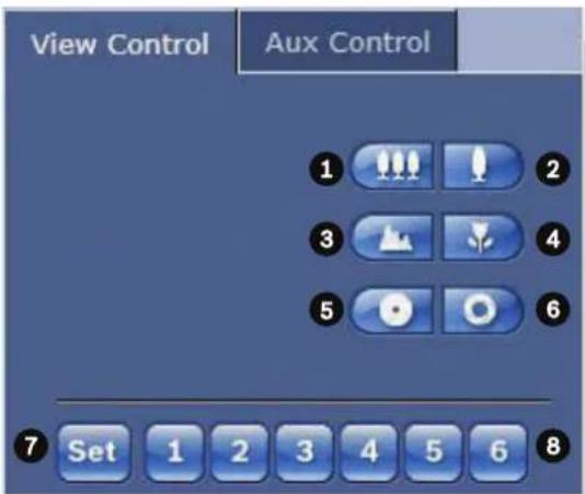
| 1 Zoom out | |
| 2 Zoom in | |
| 3 Focus far | |
| 4 Focus near | |
| 5 Iris close | |
| 6 Iris open | |
| 7 Sets | the pre-set scene for the corresponding button 1, 2, 3, 4, 5 and 6 |
| 8 Zooms | the camera to pre-set scene numbers 1, 2, 3, 4, 5 and 6 |
To control a peripheral, follow these steps:
- Click the appropriate controls.
- Move the mouse cursor over the video image. Additional options for controlling peripherals are displayed with the mouse cursor.
6.1.4 AUX Control
Aux Control Tab
The AUX Control tab is used to enter pre-programmed keyboard control commands. These commands are composed of a command number plus the appropriate function key (Show scene, Set scene, AUX on, AUX off). A valid combination either issues a command to the camera or displays an on-screen menu.
To access the AUX Control tab, go to the LIVE page and click the AUX Control tab.
(Refer to the User Command Table for a list of all AUX commands.)
By default, the device is configured for a total of 256 presets.
Some legacy systems may not support presets above 99. In this case, you can set the camera to use only presets 1-99. Enter 151 on the keypad, and then click AUX on.
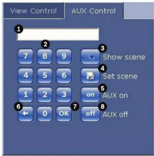
| 1 Command number field |
| 2 Keypad (numbers 0-9) |
| 3 Show a preset scene |
| 4 Set a preset scene |
| 5 Initiates a command |
| 6 Deletes a number in the Command Number field |
| 7 Used to select a menu item |
| 8 Stops a command |
To Enter a Keyboard Control Command:
- Place the cursor in the Command Number field.
- Click the desired command number via the on-screen keypad.
- Click either the Aux on button or the Aux off button to initiate or stop the command.
- If the command initiates a menu, use the Up/Down arrows on the View Control to navigate the menu. Click the Focus button or Iris button to select a menu item.
6.1.5
Presets
Preset scenes (or shots) are camera positions that are saved in memory for future use. Set presets with the zoom control option. If your computer mouse has a scroll button, you can use it to zoom in and out to set presets.
- Scroll your mouse to zoom in or out to the desired position for the preset.
- Click any number combination from 1-256 from the on-screen keypad to identify the scene number.
- Click the Set scene button. The image area displays a message that indicates which scene number was saved.
To View a Preset Shot:
- Click the number of the scene you want to view using the on-screen keypad.
- Click the Show scene button.

Notice!
For more information about the camera settings and controls, click the Help on this page? link to open the online help.
6.1.6
Digital I/O
The alarm icon is for information purposes and indicates the status of an alarm input: When an alarm is triggered, the icon lights up blue. The device's configuration determines whether the alarm is displayed, as well as additional details. Refer to the online help for more information.
Triggering Relay
You can switch connected units using the relays in the camera (for example, lights or door openers).
To activate this, click the icon for the relay next to the video image. The icon will be red when the relay is activated.
6.1.7
System Log/Event Log
System Log
The System Log field contains information about the operating status of the camera and the connection. You can save these messages automatically in a file (see the online help).
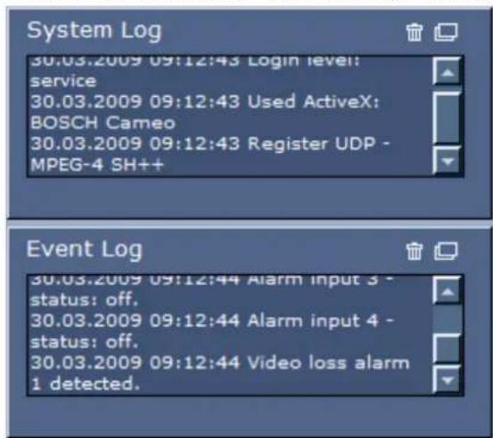
Events such as the triggering or end of alarms are shown in the Event Log field. You can save these messages automatically in a file (see the online help).
- If you want to delete the entries, click the delete icon in the top right-hand corner of the relevant field.
- If you want to view a detailed log, click the icon in the top right-hand corner of the relevant field. A new window will open.
6.1.8
Audio
Audio function
All users who are connected to the camera via Web browser can receive audio signals from the camera. Audio signals can only be sent to the camera by the user who connects to the unit first.
- On the LIVE page, click anywhere next to the video image to remove the focus from the ActiveX.
-
Hold down the F12 key to establish a voice connection to the camera. The browser's status bar displays the message Send Audio ON.
-
Release the F12 key when you want to stop sending audio signals to the camera. The status bar displays the message Send Audio OFF.

Notice!
When the voice contact connection to the camera is broken, the next user to make a connection to the camera can send audio data to the camera.
6.1.9
Saving snapshots
Saving Snapshots
You can save individual images from the video sequence currently shown on the LIVE page in JPEG format on your computer's hard drive. The icon for recording single images is only visible if the unit is configured to enable this process.
Click the icon. The storage location depends on the configuration of the camera.

6.1.10
Recording
Recording Video Sequences
You can save sections of the video sequence currently shown on the LIVE page on your computer's hard drive. The icon for recording video sequences is only visible if the unit is configured to enable this process.
Click the icon to start recording. The storage location depends on the configuration of the camera. A red dot in the icon indicates that recording is in progress.

- Click the icon again to stop recording.
- To change the storage location for the recorded video, select Advanced Mode >
Recording > Storage Management from the SETTINGS page.
Image Resolution
Sequences are saved at the resolution that has been preset in the configuration for the encoder (see Basic Mode: Network, page 8).
6.1.11
Playback
Accessing Recorded Video from the Recordings Page / PLAYBACK
Click Recordings to access the Recordings page from the LIVE page or SETTINGS page (the Recordings link is only visible if a storage medium has been selected).
Selecting Recordings
All saved sequences are displayed in a list. A track number is assigned to each sequence. Start time and stop time, recording duration, number of alarms, and recording type are displayed. To play back recorded video sequences:
- Select Recording 1 or 2 in the drop-down menu. (The contents for 1 and 2 are identical, only the quality and location may be different.)
- Use the arrow buttons to browse the list.
- Click a track. The playback for the selected sequence starts.
Export to FTP
Click Export to FTP to send the current track to the FTP server. If required, change the times within the selected range.
Controlling Playback
A time bar below the video image allows quick orientation. The time interval associated with the sequence is displayed in the bar in gray. A green arrow above the bar indicates the position of the image currently being played back within the sequence.
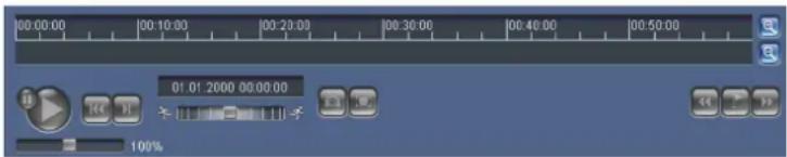
The time bar offers various options for navigation in and between sequences.
- Change the time interval displayed by clicking the plus or minus icons. The display can span a range from two months to a few seconds.
- If required, drag the green arrow to the point in time at which the playback should begin.
- Red bars indicate the points in time where alarms were triggered. Drag the green arrow to navigate to these points quickly.
Control playback by means of the buttons below the video image. The buttons have the following functions:

Start/Pause playback

Jump to start of active sequence or to previous sequence

Jump to start of the next video sequence in the list
Continuously select playback speed by means of the speed regulator (slide control):
Bookmarks
In addition, set markers in the sequences, so-called bookmarks, and jump directly to these. These bookmarks are indicated as small yellow arrows above the time interval. Use the bookmarks as follows:

Jump to the previous bookmark

Set bookmark

Jump to the following bookmark
Bookmarks are only valid while in the Recordings page; they are not saved with the sequences. All bookmarks are deleted when leaving the page.
7
Appendix
| Alarm Rule Output | Function Key | Comm. No. | Command Description | |
| Y On/Off | 7 Play Custom Pre-position Tour | Activate/Deactivate | ||
| Y On/Off | 8 Play Pre-position Tour Activate/Deactivate | |||
| Y On/Off | 20 Backlight Comp Backlight Compensation | |||
| Y On/Off | 24 Stabilization Electronic Stabilization | (Available only with the AUTODOME 7000 IP) | ||
| Y On/Off | 26 WDR/H DR Activates Wide Dynamic Range/ | High Dynamic Range | ||
| N On/Off | 40 Restore Camera Settings Restores all setting to their original defaults | |||
| Y On/Off | 43 Auto Gain Control AGC-On, Auto, Off | |||
| N 50 Playback Tour A Activate/Deactivate, Continuous | ||||
| N 51 Playback Tour A Activate/Deactivate, One Time | ||||
| N 52 Playback Tour B Activate/Deactivate, Continuous | ||||
| N 53 Playback Tour A Activate/Deactivate, One Time | ||||
| Y On/Off | 57 Night Mode setting Enables/Disables Night Mode (Day/ Night only) | |||
| Y On/Off | 60 On Screen Display On-enable | Off-disable | ||
| N On/Off | 66 Display Software Version Display software version information. Issue Once-presents basic informationIssue Twice (while basic info displayed) -presents expanded information (HD models only) | |||
| N On/Off | 67 IR Focus Correction On -Enable when external IR lamps are in use with non-IR cameras Off-disable | |||
| Y On/Off | 80 Digital Zoom Lock Turns digital zoom on and off | |||
| Y On/Off | 87 Privacy Masking On-enable | Off-disable | ||
| N On/Off | 100 Record Tour A On-start recording Off-stop recording | |||
| N On/Off | 101 Record | Tour B | On-start recording | Off- stop recording |
| N On 606 | Power Mode ` | Temporarily displays current | power mode “24 VAC:”, “POE+”, “POE++”, or “Unknown”) | |
| N On 911 | Camera Reboot Forces the camera to complete | the power on boot sequence.AUTODOME cameras will complete “Finding Home”. | ||
| Y Set 1-2 | 56 Pre-position Programming Set ### | Saves the current PTZ values as a preset view. | ||
| Y Shot 1- | 256 Pre-position Recall Shot ### | Recalls the previously saved PTZ preset position. | ||
Bosch Security Systems, Inc.
1706 Hempstead Road
Lancaster, PA, 17601
USA
www.boschsecurity.com
© Bosch Security Systems, Inc., 2015
- EXTEGRA IP 9000 FX
- BOSCH
- Browser connection
- System requirements
- Establishing the connection
- Note:
- Password protection in camera
- Protected network
- System overview
- Live page
- Playback
- Settings
- Configuration
- Configuring Audio (Optional)
- Enabling Audio Transmission
- Activating Audio Reception
- Notice!
- Configuration via IP, Basic Mode
- Basic Mode: Device Access
- Camera name
- Caution!
- Confirm password
- Basic Mode: Date/Time
- Device date/Device time/Device time zone
- Time server IP address
- Time server type
- Basic Mode: Network
- to Set and Reboot.
- DHCP
- IP address
- Subnet mask
- Gateway address
- Basic Mode: Encoder
- Non-recording profile
- Basic Mode: Audio
- Audio
- Line In
- Line Out
- Basic Mode: Recording
- Storage medium
- Basic Mode: System Overview
- Configuration via IP, Advanced Mode
- Advanced Mode: General
- Identification
- Camera ID
- Initiator extension
- Password
- Password
- Date/Time
- Date format
- Device time zone
- Daylight saving time
- Display Stamping
- Camera name stamping
- Logo
- Logo position
- Time stamping
- Display milliseconds
- Alarm mode stamping
- Alarm message
- Title OSD
- Camera OSD
- Transparent background
- Video watermarking
- Video authentication
- Signature intervals
- 5.6
- Advanced Mode: Web Interface
- Transmit audio
- Lease time (s)
- Show alarm inputs
- Show alarm outputs
- Allow snapshots
- Allow local recording
- I-frames only stream
- Show 'Special Functions'
- Path for JPEG and video files
- 5.9
- Logging
- Save event log
- File for event log
- Save system log
- File for system log
- 5.10
- Advanced Mode: Camera
- 5.11
- Installer Menu
- Factory defaults
- 5.12
- Encoder Profile
- Profile name
- Target bit rate
- Encoding interval
- Video resolution
- Expert Settings
- GOP structure
- I-frame distance
- Min. P-frame QP
- I/P-frame delta QP
- Default
- Encoder Streams
- Property
- Preview
- JPEG stream
- Picture Settings
- Current mode
- White Balance
- Red Gain
- Blue Gain
- Saturation
- Color hue
- Gain control
- Fixed Gain
- Maximum Gain Level
- AE-response speed
- Sharpness
- Shutter Mode
- Shutter
- Auto SensUP limit
- Shutter limit
- Backlight compensation
- High Sensitivity
- Stabilization
- High dynamic range
- Night mode
- Night mode threshold
- Noise Reduction
- Noise Reduction Level
- Intelligent Defog
- 5.15
- Lens Settings
- Autofocus
- Focus priority range
- Focus polarity
- Focus speed
- Auto iris
- Iris polarity
- Auto iris level
- IR focus correction
- Maximum zoom speed
- Zoom polarity
- Digital zoom
- Miscellaneous
- Fast address
- Logs
- Audio
- Input volume
- Pixel Counter
- Advanced Mode: Recording
- Storage Management
- Device manager
- Recording media
- iSCSI Media
- Local Media
- Activating and Configuring Storage Media
- Formatting Storage Media
- Deactivating Storage Media
- 5.22
- Recording Profiles
- Standard recording
- Standard profile
- Pre-alarm time
- Post-alarm time
- Post-alarm profile
- Alarm input / Analysis alarm / Video loss
- Virtual alarm
- Recording includes
- 5.23
- Maximum Retention Time
- 5.24
- Recording Scheduler
- Holidays
- Deleting Holidays
- Time periods
- Activating the Recording
- Recording status
- 5.25
- 5.26
- Advanced Mode: Alarm
- 5.27
- Alarm Connections
- Connect on alarm
- Number of destination IP address
- Destination IP address
- Destination password
- Video transmission
- Stream
- Remote port
- Video output
- Decoder
- SSL encryption
- Auto-connect
- 5.28
- VCA
- VCA configuration
- Preset
- Alarm status
- Aggregation times
- Analysis type
- Motion detector (MOTION+ only)
- Sensitivity (MOTION+ only)
- Minimum object size (MOTION+ only)
- Debounce time 1 s (MOTION+ only)
- Select Area (MOTION+ only)
- Sensitivity
- Trigger delay (s)
- Global change
- Scene too bright
- Scene too dark
- Scene too noisy
- Reference Check
- Disappearing edges
- Appearing edges
- Select Area
- Audio Alarm
- Audio alarm
- Signal Ranges
- Threshold
- 5.30
- Alarm E-Mail
- Send alarm e-mail
- Mail server IP address
- SMTP user name
- SMTP password
- Format
- Image size
- Attach JPEG from camera
- Destination address
- Sender address
- Test e-mail
- Alarm Task Editor
- Alarm Rules
- 5.33
- Advanced Mode: Interfaces
- 5.34
- Alarm Inputs
- 5.35
- Alarm Outputs
- 5.36
- Advanced Mode: Network
- 5.37
- DynDNS
- Provider
- Host name
- User name
- Force registration now
- Status
- 5.38
- Advanced
- Operation
- Authentication
- Identity
- TCP port
- Sender IP address
- 5.39
- Network Management
- SNMP
- SNMP host address / 2. SNMP host address
- SNMP traps
- UPnP
- Quality of service
- 5.40
- Multicast
- Enable
- Multicast Address
- Port
- Streaming
- Multicast packet TTL
- 5.41
- Image Posting
- File name
- Posting interval
- Target
- 5.42
- Accounts
- Type
- Account name
- Login
- Path
- Maximum bit rate
- 5.43
- IPv4 Filter
- IP Address 1 / 2
- Mask 1 / 2
- 5.44
- Encryption
- 5.45
- Advanced Mode: Service
- 5.46
- Maintenance
- Upgrading your camera
- Update server
- Firmware
- Upload
- Download
- Configuration
- Maintenance log
- 5.47
- Licenses
- 5.48
- System Overview
- Operation
- LIVE Page
- Display Stamping
- Image selection
- Image Selection
- Storage, CPU and network status
- Processor Load
- 6.1.3
- View Control
- AUX Control
- Aux Control Tab
- To Enter a Keyboard Control Command:
- 6.1.5
- Presets
- To View a Preset Shot:
- 6.1.6
- Digital I/O
- Triggering Relay
- 6.1.7
- System Log/Event Log
- System Log
- 6.1.8
- Audio function
- 6.1.9
- Saving snapshots
- 6.1.10
- Recording
- Recording Video Sequences
- Image Resolution
- 6.1.11
- Playback
- Accessing Recorded Video from the Recordings Page / PLAYBACK
- Selecting Recordings
- Export to FTP
- Controlling Playback
- Bookmarks
- 7
Brand : BOSCH
Model : Extegra NXF-9130
Category : Security Camera