DINION IP NEI-308V05 - Security Camera BOSCH - Free user manual and instructions
Find the device manual for free DINION IP NEI-308V05 BOSCH in PDF.

User questions about DINION IP NEI-308V05 BOSCH
0 question about this device. Answer the ones you know or ask your own.
Ask a new question about this device
Download the instructions for your Security Camera in PDF format for free! Find your manual DINION IP NEI-308V05 - BOSCH and take your electronic device back in hand. On this page are published all the documents necessary for the use of your device. DINION IP NEI-308V05 by BOSCH.
USER MANUAL DINION IP NEI-308V05 BOSCH
natural_image
Exterior view of a white BOSCH security camera with mounting bracket (no text or symbols visible)Dinion IP Infrared Imager
NEI-Series

BOSCH
en User Manual
Table of Contents
1 S a f e t y
1.1 Safety precautions 7
1.2 Important safety instructions 7
1.3 Important notices 8
1.4 FCC & ICES compliance 11
1.5 CSA certification - Disclaimer 12
1.6 Bosch notices 13
| 2 Description | 14 | |
| 2.1 Overview of Features | 14 | |
| 2.2 Unpacking | 16 | |
| 2.2.1 | Parts Included with the Product | 16 |
| 2.2.2 | User-supplied Parts | 16 |
| 2.2.3 | Required Tools (User-Supplied) | 17 |
| 3 Planning | 18 |
| 3.1 Pre-installation Checklist | 20 |
| 4 Installation | 22 |
| 4.1 Overview of Installation Steps | 22 |
| 4.2 Mount the Junction Box | 23 |
| 4.3 Route Wires and Attach Connectors | 24 |
| 4.3.1 About Alarm Output Connections | 26 |
| 4.4 Attach Pendant Arm to Junction Box | 27 |
| 5 Ethernet Connection (IP models) | 28 |
| 5.1 About the Ethernet Connection | 28 |
| 5.2 Connecting the NEI-30 to the PC | 28 |
| 6 Manual Camera Settings | 30 | |
| 6.1 Adjusting Focus, Focal Length, Pan, and Tilt | 30 | |
| 6.1.1 | Accessing the Rear Controls | 30 |
| 6.1.2 | Adjusting the Focus and Focal Length | 31 |
| 6.1.3 | Making Pan Adjustments | 32 |
| 6.1.4 | Making Tilt Adjustments | 32 |
4 en | Table of Contents Dinion IP Infrared Imager
6.2 Adjusting Angle of LED Tilt and Width of Illumination Beam 33
6.2.1 Adjusting the Angle of LED Tilt 33
6.2.2 Adjusting the Illumination Beam Width 34
7 Operation via the Browser 36
7.1 System Requirements 36
7.2 Configuring the NEI-30 Camera 37
7.3 The LIVEPAGE 38
7.3.1 Digital I/O 38
7.3.2 System Log / Event Log 39
7.3.3 Saving Snapshots 39
7.3.4 Recording Video Sequences 40
7.4 Settings 40
8 Configuration via IP, Basic Mode 43
8.1 Basic Mode: Device Access 43
8.2 Basic Mode: Date/Time 44
8.3 Basic Mode: Network 45
8.4 Basic Mode: Encoder 46
8.5 Basic Mode: Recording 46
8.6 Basic Mode: System Overview 47
9 Configuration via IP, Advanced Mode 48
9.1 Advanced Mode: General 48
9.1.1 Identification 48
9.1.2 Password 49
9.1.3 Date/Time 50
9.1.4 Display Stamping 51
9.2 Advanced Mode: Web Interface 53
9.2.1 Appearance 53
9.2.2 LIVEPAGE Functions 54
9.2.3 Logging 55
9.3 Advanced Mode: Camera 56
9.3.1 Picture Settings: Mode 56
9.3.2 Picture Settings: ALC 57
9.3.3 Picture Settings: Shutter/AGC 57
9.3.4 Picture Settings: Day/Night 58
9.3.5 Picture Settings: Illuminator 59
9.3.6 Picture Settings: Enhance 60
9.3.7 Picture Settings: Color 60
9.3.8 Encoder Profile 61
9.3.9 Encoder Streams 64
9.3.10 Privacy Masks 65
9.3.11 Installer Menu 66
9.4 Advanced Mode: Recording 67
9.4.1 Storage Management 67
9.4.2 Recording Profiles 69
9.4.3 Retention Time 72
9.4.4 Recording Scheduler 72
9.4.5 Recording Status 74
9.5 Advanced Mode: Alarm 74
9.5.1 Alarm Connections 74
9.5.2 VCA 77
9.5.3 Alarm E-Mail 84
9.5.4 Alarm Task Editor 85
9.6 Advanced Mode: Interfaces 86
9.6.1 Relay 86
9.7 Advanced Mode: Network 87
9.7.1 Network Access 87
9.7.2 Advanced 90
9.7.3 Multicast 92
9.7.4 FTP Posting 94
9.7.5 Encryption 95
9.8 Advanced Mode: Service 95
9.8.1 Maintenance 95
9.8.2 Licenses 97
9.8.3 System Overview 97
10 Operation via Keyboard and OSD Menus 98
10.1 Menus 98
10.1.1 Top level menus 98
10.1.2 Menu navigation 98
10.2 Pre-defined modes 99
10.3 Main menu structure 101
6 en | Table of Contents Dinion IP Infrared Imager
10.3.1 Mode submenu 101
10.3.2 ALC submenu 102
10.3.3 Shutter/AGC submenu 103
10.3.4 Day/Night submenu 105
10.3.5 Illuminator submenu 106
10.3.6 Enhance / Dynamic Engine submenu 107
10.3.7 Color submenu 108
10.3.8 VMD submenu 109
10.4 Install menu structure 110
10.4.1 Lens Wizard submenu 110
10.4.2 Language submenu 111
10.4.3 Privacy Masking submenu 111
10.4.4 Synchronization submenu 112
10.4.5 Alarm Output submenu 112
10.4.6 Connections submenu 113
10.4.7 Test Signals submenu 113
10.4.8 Camera ID submenu 114
10.4.9 Defaults submenu 114
11 Maintenance 115
11.1 Repairs 115
11.2 Transfer and Disposal 115
12 Technical Data 116
Index 118
1 S a f e t y
1.1 Safety precautions
DANGER!
High risk: This symbol indicates an imminently hazardous situation such as “Dangerous Voltage” inside the product. If not avoided, this will result in an electrical shock, serious bodily injury, or death.

WARNING!
Medium risk: Indicates a potentially hazardous situation. If not avoided, this could result in minor or moderate bodily injury.

CAUTION!
Low risk: Indicates a potentially hazardous situation. If not avoided, this could result in property damage or risk of damage to the unit.

NOTICE!
This symbol indicates information or a company policy that relates directly or indirectly to the safety of personnel or protection of property.
1.2 Important safety instructions
Read, follow, and retain all of the following safety instructions. Heed all warnings on the unit and in the operating instructions before operating the unit.
- Clean only with dry cloth.
- Do not block any ventilation openings. Install in accordance with manufacturer's instructions.
-
Do not install near any heat sources such as radiators, heat registers, stoves or other apparatus (including amplifiers) that produce heat.
-
Protect the power cord from being walked on or pinched particularly at plugs, convenience receptacles, and the power where they exit from the apparatus.
- Use only attachments/accessories specified by the manufacturer.
- Refer all servicing to qualified service personnel. Servicing is required when the apparatus has been damaged in a way, such as power-supply cord or plug is damaged, liquid has been spilled or objects have fallen into the apparatus, does not operate normally, or has dropped. When servicing, power shall be disconnected.
1.3 Important notices

natural_image
Silhouette of a person assembling a ladder inside a circular frame (no text or symbols)Accessories - Do not place this unit on an unstable stand, tripod, bracket, or mount. The unit may fall, causing serious injury and/or serious damage to the unit. Use only with the cart, stand, tripod, bracket, or table specified by the manufacturer. When a cart is used, use caution and care when moving the cart/ apparatus combination to avoid injury from tip-over. Quick stops, excessive force, or uneven surfaces may cause the cart/unit combination to overturn. Mount the unit per the manufacturer's instructions.
All-pole power switch - Incorporate an all-pole power switch, with a contact separation of at least 3 mm in each pole, into the electrical installation of the building. If it is needed to open the housing for servicing and/or other activities, use this all-pole switch as the main disconnect device for switching off the voltage to the unit.
Camera signal - Protect the cable with a primary protector if the camera signal is beyond 140 feet, in accordance with NEC800 (CEC Section 60).

CAUTION!
This product has been tested according to standard CIE/IEC 62471:2006 “Photobiological safety of lamps and lamp systems” and found to meet Risk Group 2 for exposure limit 4.3.7 “Infrared radiation hazard exposure limits for the eye.” For other hazard exposure limits, the product was found to be exempt. Risk Group 2 is characterized in the standard as “products generally do not pose a realistic optical hazard if aversion responses limit the exposure duration or where lengthy exposures are unrealistic.” Since there is no aversion response for IR, avoid eye exposure. Risk Group 2 sources do not pose an infrared radiation hazard for the eye within 10 s at distances beyond 200 mm or 8 inches. The Exposure Hazard Value for the product (ratio of the Exposure level to the Exposure limit) is up to 10 at a test distance of 200 mm (8 inches). The Hazard Distance (distance beyond which the product falls into the exempt/safe group) is at most 640 mm (25 inches). Note that typical use cases are well beyond the Hazard Distance. When servicing the unit, physically disconnect the power supply to avoid possible IR exposure to the eyes. If physical disconnection is not possible, use appropriate shielding to block the LED panel or use eye protection with a transmission of 10% or less at a wavelength of 850 nm.
Coax grounding:
- Ground the cable system if connecting an outside cable system to the unit.
- Connect outdoor equipment to the unit's inputs only after this unit has had its grounding plug connected to a grounded outlet or its ground terminal is properly connected to a ground source.
- Disconnect the unit's input connectors from outdoor equipment before disconnecting the grounding plug or grounding terminal.
- Follow proper safety precautions such as grounding for any outdoor device connected to this unit.
U.S.A. models only - Section 810 of the National Electrical Code, ANSI/NFPA No.70, provides information regarding proper grounding of the mount and supporting structure, grounding of the coax to a discharge unit, size of grounding conductors, location of discharge unit, connection to grounding electrodes, and requirements for the grounding electrode.

natural_image
Symbol of a trash bin with crossed lines indicating no waste or restriction (no text or numbers present)Disposal - Your Bosch product was developed and manufactured with high-quality material and components that can be recycled and reused. This symbol means that electronic and electrical appliances, which have reached the end of their working life, must be collected and disposed of separately from household waste material.
Separate collecting systems are usually in place for disused electronic and electrical products. Please dispose of these units at an environmentally compatible recycling facility, per European Directive 2002/96/EC.
Electronic Surveillance - This device is intended for use in public areas only. U.S. federal law strictly prohibits surreptitious recording of oral communications.
Environmental statement - Bosch has a strong commitment towards the environment. This unit has been designed to respect the environment as much as possible.
Fuse rating - For protection of the device, the branch circuit protection must be secured with a maximum fuse rating of 16A. This must be in accordance with NEC800 (CEC Section 60).
Moving - Disconnect the power before moving the unit. Move the unit with care. Excessive force or shock may damage the unit and the hard disk drives.
Outdoor signals - The installation for outdoor signals, especially regarding clearance from power and lightning conductors and transient protection, must be in accordance with NEC725 and NEC800 (CEC Rule 16-224 and CEC Section 60).
Permanently connected equipment - Incorporate a readily accessible disconnect device external to the equipment.
Pluggable equipment - Install the socket outlet near the equipment so it is easily accessible.
Power resupply - If the unit is forced to power down due to exceeding the specified operating temperatures, disconnect the power cord, wait for at least 30 seconds, and then reconnect the power cord.
Power lines - Do not locate the camera near overhead power lines, power circuits, or electrical lights, nor where it may contact such power lines, circuits, or lights.
SELV - All the input/output ports are Safety Extra Low Voltage (SELV) circuits. SELV circuits should only be connected to other SELV circuits.
Because the ISDN circuits are treated like telephone-network voltage, avoid connecting the SELV circuit to the Telephone Network Voltage (TNV) circuits.
Video loss - Video loss is inherent to digital video recording; therefore, Bosch Security Systems cannot be held liable for any damage that results from missing video information. To minimize the risk of lost digital information, Bosch Security Systems recommends multiple, redundant recording systems, and a procedure to back up all analog and digital information.

NOTICE!
This is a class B product. In a domestic environment this product may cause radio interference, in which case the user may be required to take adequate measures.
1.4 FCC & ICES compliance
FCC Information (U.S.A. and Canadian Models Only)
This equipment has been tested and found to comply with the limits for a Class B digital device, pursuant to part 15 of the FCC Rules. These limits are designed to provide reasonable protection against harmful interference in a residential installation. This equipment generates, uses, and can radiate radio frequency energy and, if not installed and used in accordance with the instructions, may cause harmful interference to radio communications. However, there is no
guarantee that interference will not occur in a particular installation. If this equipment does cause harmful interference to radio or television reception, which can be determined by turning the equipment off and on, the user is encouraged to try to correct the interference by one or more of the following measures:
- reorient or relocate the receiving antenna;
– increase the separation between the equipment and receiver; - connect the equipment into an outlet on a circuit different from that to which the receiver is connected;
- consult the dealer or an experienced radio/TV technician for help.
Intentional or unintentional modifications, not expressly approved by the party responsible for compliance, shall not be made. Any such modifications could void the user's authority to operate the equipment. If necessary, the user should consult the dealer or an experienced radio/television technician for corrective action.
The user may find the following booklet, prepared by the Federal Communications Commission, helpful: How to Identify and Resolve Radio-TV Interference Problems. This booklet is available from the U.S. Government Printing Office, Washington, DC 20402, Stock No. 004-000-00345-4.
1.5 CSA certification - Disclaimer
CSA has not tested the performance or reliability of the security or signaling aspects of this product. CSA has only tested fire, shock and/or casualty hazards as outlined in CSA's Standard(s) for Safety for Closed Circuit Television Equipment, UL 2044. CSA Certification does not cover the performance or reliability of the security or signaling aspects of this product.
CSA MAKES NO REPRESENTATIONS, WARRANTIES, OR CERTIFICATIONS WHATSOEVER REGARDING THE PERFORMANCE OR RELIABILITY OF ANY SECURITY OR SIGNALING RELATED FUNCTIONS OF THIS PRODUCT.
1.6 Bosch notices
Copyright
This manual is the intellectual property of Bosch Security Systems and is protected by copyright. All rights reserved.
Trademarks
All hardware and software product names used in this document are likely to be registered trademarks and must be treated accordingly.
NOTE:
This manual has been compiled with great care and the information it contains has been verified thoroughly. The text was complete and correct at the time of printing. The ongoing development of products means that the content of the user guide can change without notice. Bosch Security Systems accepts no liability for damage resulting directly or indirectly from faults, incompleteness or discrepancies between the user guide and the product described.
More information
For more information, please contact the nearest Bosch Security Systems location or visit www.boschsecurity.com
2 Description
The NEI-30 IP IR Imager is a high-performance, CCD-based day/night IP camera and built-in infrared illuminator, with outdoor, all-weather housing and bracketry (rated to IP67).
The NEI-30 is easy to install and ready to use, and offers the best solution for demanding scene conditions. Features include:
- True Day/Night performance with switchable IR filter and Auto Photocell switching mode
– Illuminator with variable field illumination - H.264 encoding
- Pre-installed video content analysis (VCA)
- Power over Ethernet plus (PoE+)
- Complies with ONVIF standard for wide compatibility
- Ability to display images from one camera on several monitors/receivers
- Progressive scan
- 540 TVL resolution
- Dynamic engine with Smart BLC
- Privacy masks
- Wide operating temperature range (-40°C to +50°C / -40°F to +122°F)
- Six pre-programmed operation modes
- Adaptive dynamic noise reduction
- Multiple language on-screen display
- Easy integration with existing CCTV systems / networks
2.1 Overview of Features
The NEI-30 includes the following functionality:
| Function Description | |
| Video Encoding | The camera uses the H.264 compression standards and ensures that the data rate remains low even with high image quality and can also be adapted to local conditions within wide limits. |
| Dual Streaming | Encodes dual data streams simultaneously according to two individually customized profiles. This feature creates two (2) data streams per camera that can serve different purposes. For example, one (1) data stream for local recording and one (1) data stream optimized for transmission over the Local Area Network (LAN). |
| Multicast | Enables simultaneous, real-time transmission to multiple receivers. The network must implement the UDP and IGMP V2 protocols as a prerequisite for Multicast. |
| Configuration Allows | Iows configuration for all camera settings from a Web browser on the local network (Intranet) or on the Internet. You can also update the firmware, load device configurations, store configuration settings, and copy these settings from one camera to another. |
| Snapshots Allows | you to take and store individual video frames as JPEG images from the Web browser interface. |
| Record Allows con | configuration for the recording options of the IP module. You can record video from the LIVEPAGE to a hard drive or you can opt to store up to 8 MB of video on the IP module. |
2.2 Unpacking
This electronic equipment should be unpacked and handled carefully. If an item appears to have been damaged in shipment, notify the shipper immediately.
Verify that all the parts listed in the Parts List below are included. If any items are missing, notify your Bosch Security Systems Sales or Customer Service Representative.
The original packing carton is the safest container in which to transport the unit and must be used if returning the unit for service. Save it for possible future use.
2.2.1 Parts Included with the Product
| Quantity | Item |
| 1 IR Imager camera (VEI-30 model or NEI-30 model) | |
| 1 Cable-managed pan/tilt bracket | |
| 1 | J u n c t i o |
| 1 | S u n s h i e |
| 1 3D Diffuser | |
| 3 Hex keys (1x 5 mm hex key; 1x 2.5 mm hex key; 1x 4 mm hex key) | |
| 2 Screws for adjusting the tilt of the LED (one 25 mm; one 31 mm) | |
| 1 Corner mount kit (optional) | |
| 1 Mast mount kit (optional) | |
| 1 Quick Install Guide | |
| 1 Product CD | |
2.2.2 User-supplied Parts
| Quantity | Item |
| 4 Lag bolts, 1/4-9 x 2 (M7-0.35 x 50) with 1/2 in. head | |
| 4 12 mm | (1/2 in.) washers |
| 2 20 mm | (3/4 in.) NPS watertight pipe fittings OR15 mm (1/2 in.) NPS watertight pipe fittings |
| -- Stranded wire (AWG 16 to 22) ORSolid wire (AWG 16 to 26) | |
| -- Metal conduit (for protection of power cables and input/output cables) | |
| -- Mounting hardware (such as a corner mount adapter or pole mount adapter, available separately from Bosch) | |
2.2.3 Required Tools (User-Supplied)
| Quantity | Item |
| 1 2.5 mm | (0.1 in.) straight-blade screwdriver |
| 1 | S o c k e |
| 1 14 mm | (9/16 in.) socket |
| 1 | D r i l l |
| 1 5.5 mm | (7/32 in.) drill bit |
t w
3 Planning
This equipment should be unpacked and handled carefully. If an item appears to have been damaged in shipment, notify the shipper immediately.
Verify that all the parts listed in the Parts List below are included. If any items are missing, notify your Bosch Security Systems Sales or Customer Service Representative.
The original packing carton is the safest container in which to transport the unit and must be used if returning the unit for service. Save it for possible future use.
Parts Included with the Product
| Quantity | Item |
| 1 IR Imager camera (VEI-30 model or NEI-30 model) | |
| 1 Cable-managed pan/tilt bracket | |
| 1 | J u n c t i |
| 1 | S u n s h i |
| 1 3D Diffuser | |
| 3 Hex keys (1x 5 mm; 1x 2.5 mm; 1x 4 mm) | |
| 2 Screws for adjusting the LED tilt (1x 25 mm; 1x 31 mm) | |
| 1 Corner mount kit (optional) | |
| 1 Mast mount kit (optional) | |
| 1 Quick Install Guide (this booklet) | |
| 1 Product CD with complete User Manual | |
o n e l
User-Supplied Parts
| Quantity | Item |
| 4 Lag bolts | ts, 1/4-9 x 2 (M7-0.35 x 50) with 1/2 in. head |
| 4 12 mm | (1/2 in.) washers |
| 2 20 mm | (3/4 in.) NPS watertight pipe fittings OR 15 mm (1/2 in.) NPS watertight pipe fittings |
| -- Stranded wire | (AWG 16 to 22) OR Solid wire (AWG 16 - 26) |
| -- Metal conduit (for protection of power cables and input/output cables) | |
| -- Mounting hardware (such as a corner mount adapter or pole mount adapter, available separately from Bosch) | |
Required Tools (User-supplied)
- 2.5 mm (0.1 in.) straight-blade screwdriver
- Socket wrench; 14 mm (9/16 in.) socket
- Drill; 5.5 mm (7/32 in.) drill bit

WARNING!
IMPORTANT MOUNTING INSTRUCTIONS
This apparatus must be securely attached to the wall in accordance with these installation instructions. Failure to follow installation instructions may result in injury or death.

CAUTION!
Ensure that the selected location is protected from falling objects, accidental contact with moving objects, and unintentional interference from personnel. Follow all applicable building codes.
Select a suitable location that protects the camera from accidental damage, tampering and environmental conditions exceeding the specifications of the camera.
Follow these mounting guidelines:
- Locate the camera such that it cannot be easily interfered with, either intentionally or accidentally.
- Select a smooth, flat mounting surface that can support the combined weight of the camera and mounting hardware under all expected conditions of vibration and temperature. Recommended mounting height is at least 4 m (13 ft); however, optimal conditions will vary with the specific installation environment.
3.1 Pre-installation Checklist

WARNING!
This installation must be made by a qualified service person and must conform to all local codes.

WARNING!
CSA Certified / UL Listed CLASS 2 (or Certified PoE+ rated 42.5 VDC to 57 VDC, 600 mA, 34.20 W (max), for IP models) power adapters must be used in order to comply with electrical safety standards.
- Determine the location and distance for the junction box based on its voltage and current consumption.
See the Installation Manual on the product CD for wiring information and distances. - Use only UL-listed liquid tight strain reliefs for conduits to the junction box to ensure that water cannot enter the box. You must use 3/4 in. (20 mm) NPS watertight conduits and fittings (to meet NEMA 4X standards).

WARNING!
Power and I/O cabling must be routed separately inside different permanently earthed metal conduits.
- Route all rough wiring including: power, control, video coax, alarms I/O, and relay I/O. See Section 5 Ethernet Connection (IP models), page 28 the Installation Manual on the product CD for video and control protocol methods.

WARNING!
Install external interconnecting cables in accordance with NEC, ANSI/NFPA70 (for US application) and Canadian Electrical Code, Part I, CSA C22.1 (for CAN application), and in accordance with local country codes for all other countries. CSA Certified / UL Listed CLASS 2 power adapters must be used in order to comply with electrical safety standards. Branch circuit protection incorporating a 20 A, 2-pole Listed Circuit Breaker or Branch Rated Fuses are required as part of the building installation. A readily-accessible 2-pole disconnect device with a contact separation of at least 3 mm must be incorporated.
- Select the appropriate mounting kit to use, depending on the location of the VEI-30 / NEI-30 Series camera. The camera is intended to be mounted securely to a wall using the mounting holes in the junction box.

CAUTION!
Select a rigid mounting location to prevent excessive vibration to the camera.
4 Installation

CAUTION!
Installation must be made by qualified service personnel and must conform to the National Electrical Code and all applicable local codes.
WARNING!
IMPORTANT MOUNTING INSTRUCTIONS
The camera must be attached securely to the wall in accordance with these installation instructions. Failure to follow installation instructions may result in injury or death.

The camera has been evaluated for wall mounting, through the mounting holes in the junction box, using the following hardware secured into a 2 x 4 stud under 1/2 in. drywall:
- Four (4) Lag bolts, 1/4-9 x 2 (M7-0.35 x 50) with 1/2 in. head
- Four (4) 12 mm (1/2 in.) flat washers
The camera has not been evaluated for safety requirements using other mounting kits.
4.1 Overview of Installation Steps
Follow these steps in sequence to mount the camera to a wall:
- Mount the junction box. See Section 4.2 Mount the Junction Box, page 23.
- Route wires and attach connectors for power, telemetry, and video. See Section 4.3 Route Wires and Attach Connectors, page 24.
- Attach pendant arm to junction box. See Section 4.4 Attach Pendant Arm to Junction Box, page 27.
4.2 Mount the Junction Box
natural_image
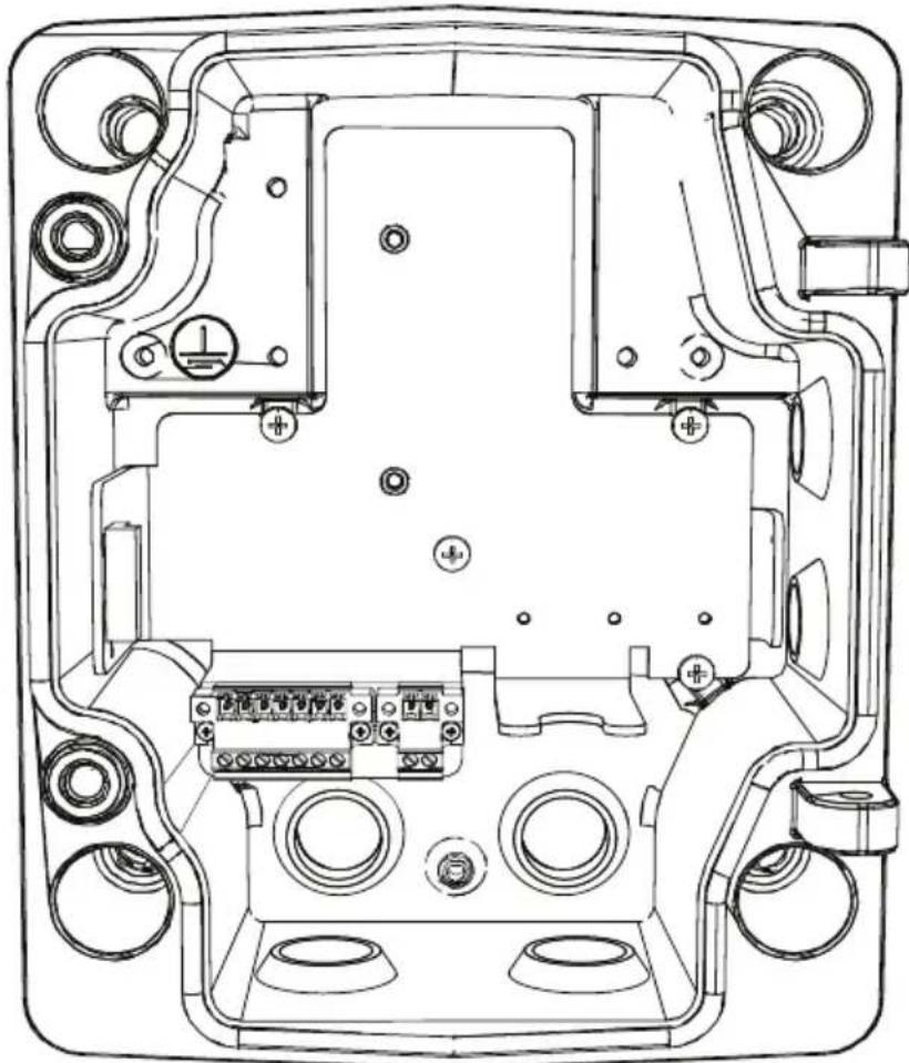
Technical line drawing of an electronic device casing with internal components and mounting holes (no text or symbols)Figure 4.1 Interior of the Junction Box
- Decide which holes in the junction box to use to insert the power wires, video, and control data wires: the holes in the bottom of the box, the holes in the back of the box, or the holes in the side of the box.
- If necessary, before mounting, move the two (2) seal plugs to the holes that you are not using. For example, if you are using the holes in the back of the box, move the plugs to cover the holes in the bottom of the box.
- Locate studs in the wall and mark the outside edges of the studs.
- Using the wall mount bracket as a template, align the mounting holes with the center of the studs.
-
Mark the points on the wall in the center of the holes where the mounting bolts will be positioned.
-
Remove the wall mount bracket and drill pilot holes at each marked point.
- Align the mounting holes of the wall mount bracket with the holes drilled in the wall.
- Using a socket wrench and a 14 mm (9/16 in.) socket (not supplied), screw the first 1/4-9 x 2 (M7-0.35 x 50) lag bolt (not supplied) with 12 mm (1/2 in.) washer (not supplied) into the stud.
- Repeat step 8 to attach the three remaining lag bolts.
- Attach the appropriate NPS watertight pipe fittings (not supplied) to the bottom or back holes of the junction box through which to run the power, video, and other wires.

NOTICE!
You must use the appropriate UL-listed / NPS watertight conduits and fittings to ensure that water cannot enter the junction box, and to meet standards for NEMA 4X.
- Use 20 mm (3/4 in.) NPS fittings for the holes on the bottom and back of the box.
- Use 15 mm (1/2 in.) NPS fittings for the side holes.
4.3 Route Wires and Attach Connectors
-
Route all video, control, and alarm wires through the conduit fitting on the left (back) side of the junction box. These wires must be routed through a permanently earthed metal conduit. See Section 5 Ethernet Connection (IP models), page 28 the Installation Manual on the product CD for coax, UTP, and fiber optic specifications and distances.
-
Route the power lines (24 VAC / 12 VDC) through the conduit fitting on the right (front) side of the box. Use stranded wire (AWG 16 to 22) or solid wire (AWG 16 to 26). These wires must be routed through a permanently earthed metal conduit.
-
Cut and trim all wires with sufficient slack to reach their connector terminals in the box, but not so long as to be
pinched (about 5 mm (0.2 in.) of insulation). See
Figure 4.3, Page 27, above, for the connector locations.
- Loosen the screws of the supplied 2-pole connector (2-pin Power Plug) and attach the incoming power wires.
- Attach the supplied 7-pin relay output plug to the incoming relay wires.
- Tighten the screws and insert the 2-pole connector into the power socket of the camera.

NOTICE!
For a DC supply, the polarity is important. Incorrect polarity does not damage the camera, but will not allow the camera to switch on. If input voltage is not within the specified range or has incorrect polarity (DC only), the voltage indicator (a yellow LED in the front window) turns on to indicate this condition.
- Connect the incoming Ethernet cable to the RJ45 connector supplied in the camera junction box.
4.3.1 About Alarm Output Connections

text_image
NCV1 V2 T1 T2 D1 D2 ① ② ③ ④ ⑤ ⑥ ⑦Figure 4.2 Terminal Block for Alarm Output Connections
| # | Label | Description Wire | Color | Pin Connection, Terminal Block |
| 1 | NC Not connected | |||
| 2 | V1 Camera alarm output connection 1 White Pin | 6 of X4 | 53 on PCBA | |
| 3 | V2 Camera alarm output connection 2 Yellow Pin | 3 of X4 | 453 on PCBA | |
| 4 | T1 Tamper alarm output connection 1 Brown Pin | 1 of CN11 | ||
| 5 | T2 Tamper alarm output connection 2 Voltage free and either NO or NC. | Gray | Pin 2 of CN11 | |
| 6 | D1 | Illuminator on alarm output connection 1 | Black | Pin 1 of CN10 |
| 7 | D2 | Illuminator on alarm output connection 2 Voltage free and either NO (Illuminator off mode) or NC (Illuminator on mode). | Orange | Pin 2 of CN10 |
4.4 Attach Pendant Arm to Junction Box
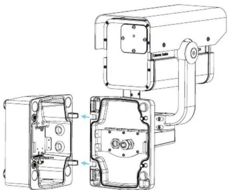
The bottom hinge pin of the camera arm has a stop to hold the hinge open while attaching the arm to the junction box.
- Compress the bottom hinge pin by pushing the pin lever downward and rotating it behind the hinge pin stop.
natural_image
Technical line drawing of a surveillance camera module with open and closed views (no text or symbols)Figure 4.3 Camera Box Hinge Alignment
- Open the top hinge by pushing and holding up the pin lever.

NOTICE!
Both hinge pins must be fully compressed to open (unlock) the hinges of the camera arm and before proceeding to step 3.
-
While continuing to hold the top hinge pin, open and align the top and bottom hinges of the camera arm to their mating points on the junction box. See Figure 4.3, above.
-
Once you have aligned the hinges, release the top hinge pin to engage its mating hinge on the junction box, and then release the bottom hinge pin from the hinge pin stop to lock the camera arm to the junction box.
DANGER!
Serious injury or death can occur if the hinge pins of the camera arm are not fully engaged (locked) to the junction box. Use caution before releasing the camera arm.
5 Ethernet Connection (IP models)
5.1 About the Ethernet Connection
The NEI-30 transmits video and control over a standard TCP/IP network using the built-in web server through which users can configure the display settings and the operating settings of the camera, and the parameters of the network to which the camera is connected. The NEI-30 connects to a 10 BASE-T/100 BASE-TX network either directly or via a hub. In addition, power can be supplied to IP camera models via the Ethernet cable compliant with Power-over-Ethernet Plus (PoE+) (IEEE 802.3at standard).

CAUTION!
Make Ethernet connections (Cat-5e or Cat-6; maximum distance 100 m (328 ft)) to non-exposed (indoor) networks only.

WARNING!
IP camera models can accept power from the 12 VDC / 24 VAC power input or from the Ethernet input. Ensure that the camera receives power from only one source.
5.2 Connecting the NEI-30 to the PC
- Install the NEI-30 according to the instructions.
- Make the desired connection between the Ethernet cable and the camera.
- Option A: Connect the RJ45 connector on the camera to a dedicated network switch to bypass the Local Area Network (LAN), and then connect the dedicated network switch to the RJ45 connector on the PC.
- Option B: Connect the RJ45 connector on the camera directly to the PC.

flowchart
graph TD
    A["Camera ①"] -->|②| B["Computer ③"]
    B -->|②| C["Computer ④"]
    D["Camera ①"] -->|②| B
    D -->|②| E["Computer ④"]
Figure 5.1 NEI-30 System Configuration
| 1 | N E I - 3 0 |
| 2 | IP Connection |
| 3 | N e t w o r k S |
| 4 | C o m p u t e r |
witch
6 Manual Camera Settings
Most camera settings can be adjusted remotely via CTFID software (for analog models; refer to the Configuration Tool for Imaging Devices User Manual at www.boschsecurity.com) or via the web browser interface (for IP models). Some settings--lens focus, focal length, pan, tilt, LED tilt, and the width of the illumination beam--require manual adjustment using controls at the back of or in the front of the camera.
6.1 Adjusting Focus, Focal Length, Pan, and Tilt
To adjust the focal length and focus, use the controls located on the access panel at the rear of the camera housing. An access panel also contains the camera keypad buttons that you use to interact with the camera's on-screen display (OSD) menu. This menu provides advanced set-up options for getting the best results under special circumstances.
6.1.1 Accessing the Rear Controls
- Unscrew the four (4) captive screws (item 1 in Figure 6.1) of the access panel on the rear of the camera housing.
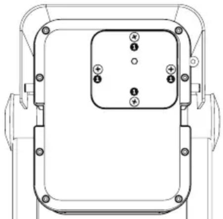
natural_image
Technical line drawing of a mechanical component with mounting holes and a central square housing (no text or symbols)Figure 6.1 Rear camera housing with access panel
- Open the access panel. Now you can adjust the focus and focal length (see Figure 6.2 below).
Note: Before you make any adjustments, you may need to connect the camera to a monitor to view the changes to the picture. See Section 5 Ethernet Connection (IP models),
page 28 for details. Refer to the complete installation manual (on CD) for details about advanced camera setup using the keypad controls.

NOTICE!
Remember to tighten the captive screws on the panel when you finish the adjustments.
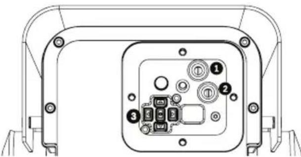
natural_image
Technical line drawing of a device rear panel with internal components (no text or symbols)Figure 6.2 Controls for focal length, focus, and camera set-up
| 1 Focal length adjustment |
| 2 Focus adjustment (zoom) |
| 3 Advanced camera set-up controls - keypad |
6.1.2 Adjusting the Focus and Focal Length
- Use the top set screw (item 1, Figure 6.2) to adjust the image focus:
- Turn the set screw to the left to focus near (N) (zoom in).
- Turn the set screw to the right to focus far (F) (zoom out).
- Use the lower set screw (item 2, Figure 6.2) to adjust the focal length (tele or wide):
- Turn the set screw to the left for a wider field of view.
- Turn the set screw to the right for a telephoto field of view.
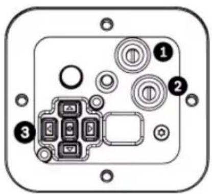
text_image
Diagram of an electronic device panel with labeled components including buttons, indicators, and a central display area.Figure 6.3 Focus and Zoom screws on the inside of the access panel on the rear of the camera housing
6.1.3 Making Pan Adjustments
- Using the 4 mm hex key, loosen the bolts at the base of the "u bracket" to make the necessary pan adjustments.
- When loosened, adjust the camera to the desired pan angle.
- Tighten the bolt to secure in place.
6.1.4 Making Tilt Adjustments
- Using the 2.5 mm hex key, unscrew the round caps (CCW) where the bracket attaches to the camera housing to expose the bolts for tilt adjustment.
- Using the 4 mm hex key, loosen the bolts.
- Make the necessary tilt adjustments.
- Tighten the bolts to secure the camera in place.
- Replace the round caps when you finish the adjustments.
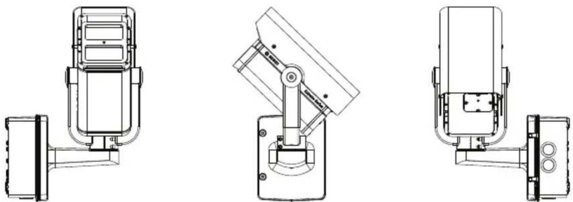
natural_image
Technical line drawings of three different surveillance cameras (no text or symbols present)Figure 6.4 Example orientation: Camera rotated 90 degrees left, pointing up 44 degrees. From left: front view, side view, back view
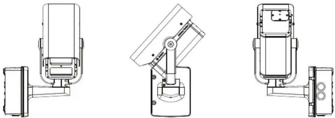
Figure 6.5 Example orientation: Camera rotated 90 degrees right, pointing down 48 degrees. From left: front view, side view, back view
6.2 Adjusting Angle of LED Tilt and Width of Illumination Beam
Adjust the angle of LED tilt and the width of the illumination beam on the front of the camera. See the figures in the subchapters below to identify the locations for each adjustment.
6.2.1 Adjusting the Angle of LED Tilt

NOTICE!
Do not discard the additional LED tilt set screw supplied in the accessory kit! It is required to adjust the angle of LED tilt.
Adjust the angle of LED tilt (up or down) to maximize coverage of the infrared light over the field of view. As a general guideline, when the camera is pointed down at a steeper angle (usually at higher installation heights or for applications of shorter ranges), the angle of LED tilt should be raised above the axis of the camera to reduce the potential of overexposure in the foreground.
-
Select the appropriate set screw for adjusting the angle of LED tilt, based on how far you want the camera to “see.” Use the 31 mm screw for general area surveillance / targets closer to the camera. Use the 25 mm screw for other use cases such as monitoring a perimeter.
-
Insert the set screw in the screw slot (item 1, Figure 6.6) between the camera window and the LED window in the front of the camera.
natural_image
Technical line drawing of a mechanical component with mounting holes and a labeled section (no text or symbols)Figure 6.6 Slot for set screw for adjusting angle of LED tilt
- Insert the screw as far as possible into the slot. The screw must be in the slot completely to make the adjustment.

WARNING!
The LED Tilt Set screw must be inserted completely so that the integrated O-ring makes a seal with the camera housing. If the screw is not completely inserted, the water tightness of the camera will be compromised.
6.2.2 Adjusting the Illumination Beam Width
Adjust the infrared beam width by adding or removing the 3D diffuser. Each camera ships with a 3D diffuser plate (already installed in the camera) and the 3D diffuser (not installed in the camera). The diffuser plate holds the 3D diffuser in place in the camera. The 3D diffuser is recommended for wider field of view applications.
- With the 3D diffuser, a focal length of 6 ~mm provides a horizontal field of view (FOV) of 42^ to match the illumination pattern; the resulting beam angle is 42^ (H) × 20^ (V) .
- Without the 3D diffuser, a focal length of 27 ~mm (or greater) provides a horizontal field of view (FOV) of 10^ (or less) to match the illumination pattern; the resulting beam angle is 10^ (H) × 10^ (V) .
To install the 3D diffuser:
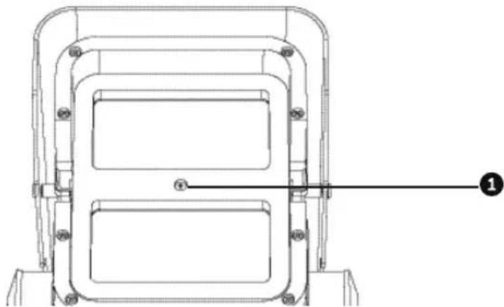
- Unscrew the four (4) captive screws beneath the illuminator in the front of the unit (item 2, Figure 6.7).

text_image
Technical diagram of a mechanical component with numbered annotations pointing to features like '①' and '②'.Figure 6.7 3D Diffuser
-
Using the captive screws, remove the 3D diffuser plate.
-
Insert the 3D diffuser into the slit in the gasket on the 3D diffuser plate.
IMPORTANT: Ensure that the diffuser is inserted into the camera housing with the sticker side facing the LED array. It is important that the diffuser is oriented with the sticker side surface facing the LED array or IR performance will be lost.
- Install the diffuser and plate assembly into the camera housing to secure and seal the unit.
To remove the 3D diffuser:
-
Remove the 3D diffuser and plate assembly as when installing the 3D diffuser.
-
Remove the 3D diffuser from the diffuser plate.
-
Install the diffuser plate into the camera housing to secure and seal the unit.
7 Operation via the Browser
7.1 System Requirements
The NEI-30 requires specific software and hardware to allow a user to view live images and to configure camera settings over a TCP/IP network. These requirements are:
- A computer with the Microsoft Windows XP or Vista operating system, network access, and the Microsoft Internet Explorer Web browser version 7.0 or later, or
- A computer with the Microsoft Windows XP or Vista operating system, network access, and reception software such as the Bosch VIDOS software or the Bosch Divar XF, or
- A compatible hardware decoder from Bosch Security Systems as a receiver and a connected video monitor.
If you choose to use a computer running Microsoft Internet Explorer or any of the Bosch software, then the computer must conform to the following minimum requirements:
- Processor: 1.8 GHz Pentium IV
- RAM: 256 MB
- Video system: 128 MB video memory, 1024x768 display with a minimum of 16-bit color
- Network interface: 100-BaseT
- Microsoft Internet Explorer, version 7.0 or higher
You must install the following software (available on the Bosch Security Systems, Inc. website at www.boschsecurity.com):
- DirectX 9.0c
- Java Virtual Machine
- MPEG ActiveX utility
- . N e t 2 . 0
- VideoSDK
Windows Vista, Internet Explorer, ActiveX, and DirectX are trademarks of Microsoft Corporation.
Pentium is a trademark of Intel Corporation.
Java is a trademark of Sun Microsystems, Inc.

NOTICE!
Ensure that the graphics card is set to 16-bit or 32-bit color. If you need further assistance, contact your PC system administrator.
7.2 Configuring the NEI-30 Camera
To operate the camera in your network, you must assign a valid network IP address to the camera. The default IP address is 192.168.0.1, but you may need to change this address if it conflicts with another device on your network. Refer to Section 8.3 Basic Mode: Network, page 45 for more information. To configure the camera for your network, you need the following information:
- Unit IP address: An identifier for the camera on a TCP/IP network. For example, 140.10.2.110 is a valid syntax for an IP address.
- Subnet mask: A mask used to determine the subnet to which an IP address belongs.
- Gateway IP address: A node on a network that serves as an entrance to another network.
- Port: An endpoint to a logical connection in TCP/IP and UDP networks. The port number identifies the use of the port for use through a firewall connection.

NOTICE!
Ensure that the network parameters of your cameras are available before you begin configuration.
The NEI-30 defaults are as follows:
- IP Address: 192.168.0.1
- Subnet Mask: 255.255.255.0
- Gateway IP Address: 0.0.0.0
The following sections provide instructions about installing the software necessary to view images over an IP connection, configuring the IP network settings, and accessing the NEI-30 images from a Web browser.
7.3 The LIVEPAGE
Once the connection is established, the Web browser displays the LIVEPAGE. It shows the live video image on the right of the browser window. Depending on the configuration, various text overlays may be visible on the live video image.

text_image
Digital I/O Camera 1 Current - Oct-01 Current - Oct-01 System Log Current - Oct-01 Camera 1 Current - Oct-01 System Log Current - Oct-01 System Log Current - Oct-01 System Log Current - Oct-01 System Log Current - Oct-01 System Log Current - Oct-01 System Log Current - Oct-01 System Log Current - Oct-01 System Log Current - Oct-01 System Log Current - Oct-01 System Log Current - Oct-01 SystemLog Current - Oct-01 SystemLog Current - Oct-01 SystemLog Current - Oct-01 SystemLog Current - Oct-01 SystemLog Current - Oct-01 SystemLog Current - Oct-01 SystemLog Current - Oct-01 SystemLog Current - Oct-01 SystemLog Current - Oct-01 SystemLog Current - Oct-01 Systemlog Current - Oct-01 Systemlog Current - Oct-01 Systemlog Current - Oct-01 Systemlog Current - Oct-01 Systemlog Current - Oct-01 Systemlog Current - Oct-01 Systemlog Current - Oct-01 Systemlog Current - Oct-01 Systemlog Current - Oct-01 Systemlog Current - Oct-01 Systemlg Current - Oct-01 Systemlg Current - Oct-01 Systemlg Current - Oct-01 Systemlg Current - Oct-01 Systemlg Current - Oct-01 Systemlg Current - Oct-01 Systemlg Current - Oct-01 Systemlg Current - Oct-01 Systemlg Current - Oct-01 Systemlg Current - Oct-01 SystemlFigure 7.1 LIVEPAGE
Other information may be shown next to live video image on the LIVEPAGE. The display depends on the settings on the Livepage Configuration page. (See the NEI-30 online help.)
7.3.1 Digital I/O

text_image
Digital I/O Relay 1The alarm icon is for information purposes and indicates the status of an alarm input: when an alarm is triggered, the icon lights up blue. The device's alarm connections and alarm rule settings determine if the alarm icons are activated.
7.3.2 System Log / Event Log
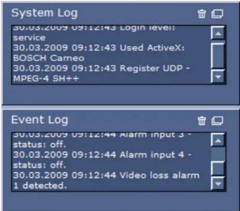
text_image
System Log 30.03.2009 09:12:43 Login level: service 30.03.2009 09:12:43 Used ActiveX: BOSCH Cameo 30.03.2009 09:12:43 Register UDP - MPEG-4 SH++ Event Log 30.03.2009 09:12:44 Alarm input 3 - status: off. 30.03.2009 09:12:44 Alarm input 4 - status: off. 30.03.2009 09:12:44 Video loss alarm 1 detected.The System Log field contains information about the operating status of the NEI-30 and the connection. You can save these messages automatically in a file (see the NEI-30 online help).
The Event Log field displays the triggering or end of alarms. You can save these messages automatically in a file (see the NEI-30 online help).
-
If you want to delete the entries, click the delete icon in the top right-hand corner of the relevant field.
-
If you want to view a detailed log, click the icon in the top right-hand corner of the relevant field. A new window opens.
7.3.3 Saving Snapshots
If your model is configured to save individual images (snapshots) from the video sequence displayed on the LIVEPAGE, you will see the following icon:

▶ Click the icon. The image is saved in JPEG format on the hard drive of your computer at a resolution of 704 × 576 pixels (4CIF). The storage location depends on the configuration of the camera.
7.3.4 Recording Video Sequences
If your model is configured to record sections of the video sequences displayed on the LIVEPAGE, you will see the following icon:

- Click the icon to start recording. A red dot in the icon indicates that recording is in progress. The video is recorded on the hard drive of your computer. The storage location depends on the configuration of the camera.
- Click the icon again to stop recording.

NOTICE!
You can play back saved video sequences using the Player from Bosch Security Systems, which can be installed from the product CD supplied.
Image Resolution
Sequences are saved at the resolution that has been preset in the configuration for the encoder (see Section 8.4 Basic Mode: Encoder, page 46).
Image Selection
You can view the image of the camera in different displays.
▶ Click one of the tabs Stream 1, Stream 2, or M-JPEG below the video image to toggle between the different displays of the camera image.
Triggering Relay
External units can be activated using the relay in the device (for example, lights or door openers).
▶ To activate this, click the icon for the relay next to the video image. The icon will be red when the relay is activated.
7.4 Settings
The SETTINGS page provides access to the configuration menu, which contains all the unit's parameters arranged in groups. You can view the current settings by opening one of the
configuration screens. You can change the settings by entering new values or by selecting a predefined value from a list field.
Starting Configuration
▶ Click the SETTINGS link in the upper section of the window. The web browser opens a new page with the configuration menu.
Navigation
- Click one of the menu items in the left window margin. The corresponding submenu appears.
- Click one of the entries in the submenu. The web browser opens the corresponding page.
There are two options for configuring the unit or checking the current settings:
- Basic Mode, in which the most important parameters are arranged in six groups that allow users to change the basic settings with a few entries and then to operate the camera. (See Section 8 Configuration via IP, Basic Mode, page 43.)
- Advanced Mode, in which all camera parameters are available, is recommended only for expert users or system support personnel. Settings that affect the fundamental functionality of the unit (such as firmware updates) can only be altered in this mode. (See Section 9 Configuration via IP, Advanced Mode, page 48.)
All parameter groups are described in this chapter in the order in which they are listed in the configuration menu, from the top of the screen to the bottom.

CAUTION!
The settings in the advanced mode should only be processed or modified by expert users or system support personnel.
All settings are backed up in the memory so they are not lost even if the power fails.
Making Changes
Each configuration screen shows the current settings. You can change the settings by entering new values or by selecting a predefined value from a list field.
▶ After each change, click Set to save the change.

CAUTION!
Save each change with the associated Set button.
Clicking the Set button saves the settings only in the current field. Changes in any other fields are ignored.
Maximum Number of Connections
If you do not connect, the unit may have reached its maximum number of connections. Depending on the unit and network configuration, each NEI-30 can have up to 25 Web browser connections or up to 50 connections via VIDOS or Bosch Video Management System.
Protected
If the NEI-30 is password-protected against unauthorized access, the Web browser displays a corresponding message and prompts you to enter the password when you attempt to access protected areas.

NOTICE!
An NEI-30 offers the option to limit the extent of access using various authorization levels (see the NEI-30 online help).
- Enter the user name and associated password in the corresponding text fields.
- Click OK. If the password is entered correctly, the Web browser displays the page that was called up.
Protected Network
If the network uses a RADIUS server for managing access rights (802.1x authentication), you must configure the NEI-30 accordingly; otherwise, no communication is possible.
8 Configuration via IP, Basic Mode
8.1 Basic Mode: Device Access
Camera name
You can give the camera a name to make it easier to identify. The name makes the task of administering multiple units in larger video monitoring systems easier, (for example, using the VIDOS or Bosch Video Management System programs).
The device name is used for the remote identification of a unit (for example, in the event of an alarm). For this reason, enter a name that makes it as easy as possible to quickly identify the location.

CAUTION!
Do not use any special characters (for example, &) in the name. Special characters are not supported by the internal recording management system and may therefore result in the Player or Archive Player being unable to play back the recording.
Password
The camera is generally protected by a password to prevent unauthorized access to the unit. You can use different authorization levels to limit access.
The NEI-30 camera operates with three authorization levels:
service, user and live.
The highest authorization level is service. After entering the correct password, you can access all the functions of the camera and change all configuration settings.
With the user authorization level, you can operate the unit and also control cameras, for example, but you cannot change the configuration.
The lowest authorization level is live. It can only be used to view the live video image and switch between the different live image displays.
You can define and change a password for each authorization level if you are logged in as service or if the unit is not password protected.

Enter the password for the appropriate authorization level. The maximum text length is 19 characters.
NOTICE!
Proper password protection is only guaranteed when all higher authorization levels are also protected with a password. If a live password is assigned, for example, you must also set a service and a user password. When assigning passwords, you should therefore always start from the highest authorization level, service, and use different passwords.
Confirm password
In each case, enter the new password a second time to eliminate typing mistakes.

NOTICE!
A new password is saved only when you click the Set button. You should therefore click the Set button immediately after entering and confirming a password.
8.2 Basic Mode: Date/Time
Device date/Device time/Device time zone
If there are multiple devices operating in your system or network, it is important to synchronize their internal clocks. For example, it is only possible to identify and correctly evaluate simultaneous recordings when all units are operating on the same time. If necessary, you can synchronize the unit with your computer's system settings.
▶ Click the Sync to PC button to copy your computer's system time to the camera.
Time server IP address
The camera can receive the time signal from a time server using various time server protocols, and then use it to set the internal clock. The unit polls the time signal automatically once every minute.
▶ Enter the IP address of a time server here.
Time server type
Select the protocol that is supported by the selected time server. Preferably, you should select the SNTP server as the protocol. This supports a high level of accuracy and is required for special applications and subsequent function extensions. Select Time server for a time server that works with the protocol RFC 868.
8.3 Basic Mode: Network
The settings on this page are used to integrate the camera into an existing network.
Some changes only take effect after the unit is rebooted. In this case, the Set button changes to Set and Reboot.
- Make the desired changes.
- Click the Set and Reboot button. The camera is rebooted and the changed settings are activated.

CAUTION!
If you change the IP address, subnet mask or gateway address, the camera is only available under the new addresses after the reboot.
DHCP
If your network uses a DHCP server for the dynamic assignment of IP addresses, you can activate acceptance of IP addresses automatically assigned to the camera.
Certain applications (VIDOS, Bosch Video Management System, Archive Player, Configuration Manager) use the IP address for the unique assignment of the unit. If you use these applications, the DHCP server must support the fixed assignment between IP address and MAC address, and must be appropriately set up so that, once an IP address is assigned, it is retained each time the system is rebooted.
IP address
Enter the desired IP address for the camera in this field. The IP address must be valid for the network.
Subnet mask
Enter the appropriate subnet mask for the selected IP address here.
Gateway address
If you want the unit to establish a connection to a remote location in a different subnet, enter the IP address of the gateway. Otherwise leave the box blank (0.0.0.0).
8.4 Basic Mode: Encoder
Default profile
You can select a profile for encoding the video signal.
You can use this to adapt the video data transmission to the operating environment (for example network structure, bandwidth, data load).
Pre-programmed profiles are available, each giving priority to different perspectives. When you select a profile, the list field displays the details.
| Profile Target | bit rate | Maximum bit rate | Encoding interval |
| High resolution 1 | 2000 kbps | 4000 kbps | 30.00 ips |
| High resolution 2 | 1500 kbps | 3000 kbps | 30.00 ips |
| Low bandwidth | 700 kbps | 1500 kbps | 30.00 ips |
| DSL 400 kbps | 500 kbps | 30.00 ips | |
| ISDN (2B) | 80 kbps | 100 kbps | 30.00 ips |
| ISDN (1B) | 40 kbps | 50 kbps | 30.00 ips |
| Modem | 20 kbps | 22 kbps | 15.00 ips |
| GSM | 7 kbps | 8 kbps | 7.50 ips |
8.5 Basic Mode: Recording
You can record the images from the camera on various local storage media or on an appropriately configured iSCSI system. Here you can select a storage medium and immediately start the recording.
Storage medium
- Select the required storage medium from the list.
- Click the Start button to start the recording immediately.
8.6 Basic Mode: System Overview
The data on this page are for information purposes only and cannot be changed. Keep a record of this information in case technical assistance is required.

NOTICE!
You can select all required text on this page with the mouse and copy it to the clipboard with the [Ctrl]+[C] key combination, for example if you want to send it via e-mail.
9 Configuration via IP, Advanced Mode
9.1 Advanced Mode: General
9.1.1 Identification
Camera ID
Each NEI-30 camera should be assigned a unique identifier that you can enter here as an additional means of identification.
Camera Name
You can give the camera a name to make it easier to identify the remote camera location (for example, in the event of an alarm). It will be displayed in the video screen if configured to do so. The camera name makes the task of administering cameras in larger video monitoring systems easier, for example using the VIDOS or Bosch Video Management System programs.
Enter a unique, unambiguous name for the camera in this field. You can use both lines for this.

CAUTION!
Do not use any special characters, for example &, in the name. Special characters are not supported by the system's internal recording management and may therefore result in the Player or Archive Player being unable to play back the recording.
You can use the second line for entering additional characters; these can be selected from a table.
- Click the icon next to the second line. A new window with the character map opens.
- Click the required character. The character is inserted into the Result field.
- In the character map, click the << and >> icons to move between the different pages of the table, or select a page from the list field.
- Click the < icon to the right of the Result field to delete the last character, or click the X icon to delete all characters.
- Click the OK button to apply the selected characters to the second line of the Camera 1 parameters. The window closes.
Initiator extension
You can attach your own text to the initiator name of the camera to make the unit easier to identify in large iSCSI systems. This text is added to the initiator name, separated from it by a full stop. You can see the initiator name in the System Overview page.
9.1.2 Password
The camera is generally protected by a password to prevent unauthorized access to the unit. Use different authorization levels to limit access.

NOTICE!
Proper password protection is only guaranteed when all higher authorization levels are also protected with a password. If a live password is assigned, for example, a service and a user password must also be set. When assigning passwords, you should therefore always start from the highest authorization level, service, and use different passwords.
Password
The NEI-30 camera operates with three authorization levels: service, user and live.
The highest authorization level is service. After entering the correct password, you can access all the functions of the camera and change all configuration settings.
With the user authorization level, you can operate the unit and also control cameras, for example, but you cannot change the configuration.
The lowest authorization level is live. It can only be used to view the live video image and switch between the different live image displays.
You can define and change a password for each authorization level if you are logged in as service or if the unit is not password-protected.
Enter the password for the appropriate authorization level here. The maximum text length is 19 characters.
Confirm password
In each case, enter the new password a second time to eliminate typing mistakes.

NOTICE!
A new password is only saved when you click the Set button. You should therefore click the Set button immediately after entering and confirming a password.
9.1.3 Date/Time
Date format
Select your required date format.
Device date/Device time
If there are multiple devices operating in your system or network, it is important to synchronize their internal clocks. For example, it is only possible to identify and correctly evaluate simultaneous recordings when all units are operating on the same time.
- Enter the current date. Since the unit time is controlled by the internal clock, there is no need to enter the day of the week – it is added automatically.
- Enter the current time or click the Sync to PC button to copy your computer's system time to the camera.
Device time zone
Select the time zone in which your system is located.
Daylight saving time
The internal clock can switch automatically between normal and daylight saving time (DST). The unit already contains the data for DST switch-overs up to the year 2018. You can use these data or create alternative time saving data if required.

NOTICE!
If you do not create a table, there will be no automatic switching. When changing and clearing individual entries, remember that two entries are usually related to each other and dependent on one another (switching to daylight time and back to standard time).
- Check whether the correct time zone is selected. If it is not correct, select the appropriate time zone for the system, and click the Set button.
- Click the Details button. A new window opens and you will see the empty table.
- Select the region or the city that is closest to the system's location from the list field below the table.
- Click the Generate button to generate data from the database in the unit and enter it into the table.
- Make changes by clicking an entry in the table. The entry is selected.
- Clicking the Delete button will remove the entry from the table.
- Select other values from the list fields below the table to change the entry. Changes are made immediately.
- If there are empty lines at the bottom of the table, for example after deletions, you can add new data by marking the row and selecting required values from the list fields.
- Click the OK button to save and activate the table.
Time server IP address
Enter the IP address of a time server here to enable the camera to receive the time signal from a time server using various time server protocols, and then use it to set the internal clock. The unit polls the time signal automatically once every minute.
Time server type
Select the protocol that the selected time server supports. Preferably, you should select the SNTP server as the protocol. This supports a high level of accuracy and is required for special applications and subsequent function extensions. Select Time server for a time server that works with the protocol RFC 868.
9.1.4 Display Stamping
Various overlays or “stamps” in the video image provide important supplementary information. These overlays can be enabled individually and are arranged on the image in a clear manner.
Camera name stamping
This field sets the position of the camera name overlay. It can be displayed at the Top, at the Bottom at a position of your choice that you can specify using the Custom option, or it can be set to Off for no overlay information.
- Select the desired option from the list.
- If you select the Custom option, additional fields appear where you can specify the exact position (Position (XY)).
- In the Position (XY) fields, enter the values for the desired position.
Time stamping
This field sets the position of the time overlay. It can be displayed at the Top, at the Bottom, at a position of your choice that you can then specify using the Custom option, or it can be set to Off for no overlay information.
- Select the desired option from the list.
- If you select the Custom option, additional fields appear where you can specify the exact position (Position (XY)).
- In the Position (XY) fields, enter the values for the desired position.
Display milliseconds
If necessary, you can also display milliseconds. This information can be useful for recorded video images; however, it does increase the processor's computing time. You can select this option only if the Time stamping function is activated. Select Off if you do not need to display milliseconds.
Alarm mode stamping
Select On to display a text message overlay in the image in the event of an alarm. It can be displayed at a position of your choice that you can specify using the Custom option, or it can be set to Off for no overlay information.
- Select the desired option from the list.
- If you select the Custom option, additional fields appear where you can specify the exact position (Position (XY)).
- In the Position (XY) fields, enter the values for the desired position.
Alarm message
Enter the message to be displayed in the image in the event of an alarm. The maximum text length is 31 characters.
Video watermarking
Select On if you want the transmitted video images to be "watermarked". After activation, all images are marked with a green W. A red W indicates that the sequence (live or saved) has been manipulated.
9.2 Advanced Mode: Web Interface
9.2.1 Appearance
On this page, you can adapt the appearance of the web interface and change the website language to meet your requirements. If necessary, you can replace the manufacturer's logo (top right) and the product name (top left) in the top part of the window with individual graphics.

NOTICE!
You can use either GIF or JPEG images. The file paths must correspond to the access mode (for example,
C:\Images\Logo.gif for access to local files, or http://www.mycompany.com/images/logo.gif for access via the Internet/Intranet).
When accessing via the Internet/Intranet, ensure that a connection is always available to display the image. The image file is not stored in the camera.
Website language
Select the language for the user interface.
Company logo
Enter the path to a suitable graphic if you want to replace the manufacturer's logo. The image file can be stored on a local computer, in the local network, or at an Internet address.
Device logo
Enter the path to a suitable graphic, if you want to replace the product name. The image file can be stored on a local computer, in the local network, or at an Internet address.

NOTICE!
If you want to use the original graphics again, simply delete the entries in the Company logo and Device logo fields.
JPEG interval
You can specify the interval at which the individual images should be generated for the M-JPEG image on the LIVEPAGE.
9.2.2 LIVEPAGE Functions
On this page, you can adapt the LIVEPAGE functions to your requirements. You can select from a variety of different options for displaying information and controls.
- Check the box for the items that are to be made available on the LIVEPAGE. The selected items are indicated by a check mark.
- Check whether the required functions are available on the LIVEPAGE.
Show relay outputs
Relay outputs appear as icons, along with their assigned names, next to the video image. If the relay is switched, the icon changes color.
Show VCA trajectories
When video content analysis (VCA) is activated, check this item to show additional information that traces the trajectories (motion lines) of objects) in the live video image (see Section 9.5.2 VCA, page 77).
Show VCA metadata
When video content analysis (VCA) is activated, additional information is displayed in the live video stream. For example, in Motion+ mode, the sensor areas for motion detection are marked.
Show event log
The event messages are displayed along with the date and time in a field next to the video image.
Show system log
The system messages are displayed along with the date and time in a field next to the video image and provide information about establishing and ending connections, for example.
Allow snapshots
You can specify whether the icon for saving individual images should be displayed below the live image. Individual images can only be saved if this icon is visible.
Allow local recording
You can specify whether the icon for saving video sequences on the local memory should be displayed below the live image.
Video sequences can only be saved if this icon is visible.
Path for JPEG and video files
-
Enter the path for the storage location of individual images and video sequences that you can save from the LIVEPAGE.
-
If necessary, click Browse to find a suitable directory.
9.2.3 Logging
Save event log
Check this option to save event messages in a text file on your local computer.
You can then view, edit and print this file with any text editor or the standard Office software.
To save the log file information:
- Click Download to obtain the log information.
- Click Save.
- Navigate to the directory in which you want to store the log information.
- Type a name for the log file and click Save.
File for event log
- Enter the path for saving the event log here.
- If necessary, click Browse to find a suitable directory.
Save system log
Check this option to save system messages in a text file on your local computer. You can then view, edit and print this file with any text editor or the standard Office software.
File for system log
- Enter the path for saving the system log here.
- If necessary, click Browse to find a suitable directory.
To save the log file information: - Click Download to obtain the log information.
- Click Save.
- Navigate to the directory in which you want to store the log information.
- Type a name for the log file and click Save.
9.3 Advanced Mode: Camera
9.3.1 Picture Settings: Mode
Current mode
Select from six (6) pre-programmed operation modes.
- 24-hour
Default installation mode to provide stable pictures over a 24-hour period. These settings are optimized for out-of-the-box installation.
- Traffic
Capture high-speed objects using default shutter in variable lighting conditions.
- Low light
Provide extra enhancement such as AGC and SensUp to make usable pictures in low-light conditions.
- Smart BLC
Settings optimized to capture details in high contrast and extremely bright-dark conditions.
- Low noise
Enhancements are set to reduce picture noise. Useful for conditional refresh DVR and IP storage systems because reducing noise reduces the amount of storage required.
- IR
Settings are configured to provide optimal imaging performance in low-light or no-light conditions.
Mode ID
Enter a name for the mode.
Copy mode to
No, 2 - 6
Mode Copied (Not Copied) When you select a mode, the Mode
Copied is "Copied!"
When you click Restore Mode Defaults, the Mode Defaults is
"Restored!"
Mode Defaults
9.3.2 Picture Settings: ALC
ALC level
Adjust the video output level (-15 to 0 to +15).
Peak average
Adjust the balance between peak and average video control (-15 to 0 to +15).
At -15, the camera controls the average video level.
At +15, the camera controls the peak video level.
Speed
Adjust the speed of the video level control loop (Slow, Medium, or Fast).
9.3.3 Picture Settings: Shutter/AGC
Shutter
- AES (auto-shutter) — The camera automatically sets the optimum shutter speed for manual iris lenses. The camera tries to maintain the selected default shutter speed (1/30, 1/60, 1/120, 1/250, 1/500, 1/1000, 1/2000, 1/5000, 1/10K) as long as the light level of the scene permits.
- FL - Flickerless mode avoids interference from light sources (recommended for use with video iris or DC iris lenses only).
- Fixed - Allows a user defined shutter speed (1/60 [1/50], 1/100, 1/120, 1/250, 1/500, 1/1000, 1/2000, 1/5000, 1/10K).
Default shutter
The default shutter is 1/60. This value does not appear for the FL Shutter mode.
Actual shutter
This non-editable field displays the actual shutter value.
Sensitivity up
This field is only for the AES Shutter mode. Selects the factor by which the sensitivity of the camera is increased (OFF, 2x, 3x, etc. to a maximum of 10x).
Note: If Sensitivity up is active, some noise or spots may appear in the picture. This is normal camera behavior.
Sensitivity up may cause some motion blur on moving objects.
Gain
In AGC mode, the camera automatically sets the gain to the lowest possible value needed to maintain a good picture. Select the Maximum gain value that the camera can have during AGC operation(0-28).
In Fixed mode, it sets the Fixed AGC mode.
Maximum gain
For AGC mode, select the value of maximum gain that the camera can have during AGC operation (0-28).
Actual gain
This non-editable field displays the actual gain value.
9.3.4 Picture Settings: Day/Night
The NEI-30 camera is equipped with a motorized IR filter. The IR filter can be removed in low-light or IR-illuminated applications to increase the IR sensitivity and enhance night viewing. There are three different methods of switching:
- as part of the programmable mode profile,
– automatically, based on the observed light levels, or - via the settings page.
Day/night
If Auto Video switching mode is selected, the camera automatically switches the filter depending on the video and Priority setting. The switching level is programmable.
In Monochrome mode, the IR filter is removed, giving full IR sensitivity.
Switch level
Set the video Switch level at which the camera switches to monochrome operation (-15 to 0 to +15). A low (negative) value means that the camera switches to? monochrome at a lower light (lux) level. A high (positive) value means that the camera switches to monochrome at a higher light (lux) level.
If you select Auto Photocell switching mode, the camera automatically switches the filter depending on the ambient light level. The switching level is programmable by adjusting the switch level.
Priority
In Auto Video switching mode, set the camera priority:
- Motion - The camera gives sharp images without motion blur as long as the light level permits.
- Color - The camera gives color pictures as long as the light level permits.
The camera recognizes IR-illuminated scenes to prevent unwanted switching to color mode.
IR contrast
There are two modes for IR contrast:
- Enhanced - The camera optimizes contrast in applications with high IR illumination levels.
- Normal - The camera optimizes contrast in mono applications with visible light illumination.
Color burst
Select On to activate color burst. Select Off to deactivate it.
9.3.5 Picture Settings: Illuminator
IR function
- On - The illuminator is always on, regardless of the level of ambient light.
- Off - The illuminator remains off, regardless of the level of ambient light.
- Auto - The camera switches the illuminator's cut-off filter on and off depending on the Day/Night mode.
Intensity level
Adjusts the intensity of the illuminator light (0 to 30); 30 is the default.
9.3.6 Picture Settings: Enhance
Dynamic engine
Select from Off, XF Dynamic, 2x Dynamic, or Smart BLC.
Auto black
Auto black ON automatically increases the visibility of details.
Sharpness
Adjusts the black level (-15 to 0 to +15). Zero is the factory default.
Dynamic noise reduction
In AUTO mode, the camera automatically reduces the noise in the picture. This may cause some motion blur on moving objects.
Peak white
Select On to activate peak white invert. Select Off to deactivate it.
9.3.7 Picture Settings: Color
White balance
- ATW - Auto tracking white balance allows the camera to adjust constantly for optimal color reproduction.
- AWB hold - Puts the ATW on hold and saves the color settings.
- In Manual mode, the Red, Green, and Blue gain can be set manually to a desired position.
Speed
This option is available only for ATW white balance. Adjust the speed (Fast, Medium, Slow) of the white balance control loop.
R-gain
Offsets factory white point alignment (reducing red introduces more cyan) (-50 to 0 to +50).
G-gain
ATW mode and AWB hold mode: adjusts the Green gain (-50 to 0 to +50) to optimize the white point.
B-gain
Offsets factory white point alignment (reducing blue introduces more yellow) (-50 to 0 to +50).
It is only necessary to change the white point offset for special scene conditions.
Saturation
Adjusts the color saturation (-15 to 0 to +5) so as to make the reproduction of colors on your monitor as realistic as possible; -15 gives a monochrome image.
9.3.8 Encoder Profile
For the video signal encoding, you can select a code algorithm and you can change the presets for the profiles.
You can adapt the video data transmission to the operating environment (for example network structure, bandwidth, data load). To this end, the camera simultaneously generates two data streams (Dual Streaming), which compression settings you can select individually, for example one setting for transmissions to the Internet and one for LAN connections.
Pre-programmed profiles are available, each giving priority to different perspectives.
| Profile Target | bit rate | Maximum bit rate | Encoding interval |
| High Resolution 1 | 2000 kbps | 4000 kbps | 30.00 ips |
| High Resolution 2 | 1500 kbps | 3000 kbps | 30.00 ips |
| Low Bandwidth 700 kbps 1500 kbps 30.00 ips | |||
| DSL 400 kbps 500 kbps 30.00 ips | |||
| ISDN (2B) 80 kbps 100 kbps 30.00 ips | |||
| ISDN (1B) 40 kbps 50 kbps 30.00 ips | |||
| Modem 20 kbps 22 kbps 15.00 ips | |||
| GSM 7 kbps 8 kbps 7.50 ips | |||
You can change individual parameter values of a profile and you can also change the name. You can switch between profiles by clicking the appropriate tabs.

CAUTION!
The profiles are rather complex. They include a large number of parameters that interact with one another. In general, it is best to use the default profiles.
Change the profiles only once you are fully familiar with all the configuration options.
In the default setting, Stream 2 is transmitted for alarm connections and automatic connections. Keep this fact in mind when assigning the profile.

NOTICE!
All parameters combine to make up a profile and are dependent on one another. If you enter a setting that is outside the permitted range for a particular parameter, the nearest permitted value will be substituted when the settings are saved.
Profile name
You can enter a new name for the profile here. The name is then displayed in the list of available profiles in the Profile name field.
Target bit rate
You can limit the data rate for the camera to optimize utilization of the bandwidth in your network. The target data rate should be set according to the desired picture quality for typical scenes with no excessive motion.
For complex images or frequent changes of image content due to frequent movements, this limit can be temporarily exceeded up to the value you enter in the Maximum data rate field.
Maximum bit rate
This maximum data rate is not exceeded under any circumstances. Depending on the video quality settings for the I- and P-frames, this fact can result in individual images being skipped.
The value entered here must be at least 10% higher than the value entered in the Target data rate field. If the value entered here is too low, it will automatically be adjusted.
Encoding interval
The figure selected here determines the interval at which images are encoded and transmitted. The image rate in ips (images per second) is displayed next to the text field. Use the slide bar to select a frame rate from 30.00 ips to 1 ips.
Video resolution
Here you can select the desired resolution for the video image. The following resolutions are available:
- CIF
$$ 3 5 2 \times 2 8 8 / 2 4 0 \text { pixels } $$
- 4CIF/D1
$$ 7 0 4 \times 5 7 6 / 4 8 0 \text { pixels } $$
Use the expert settings to adapt the I-frame quality and the P-frame quality to specific requirements, if necessary. The setting is based on the H.264 quantization parameter (QP).
GOP structure
Select the structure you require for the Group of Pictures here. Depending on whether you place greater priority on having the lowest possible delay (IP frames only) or using as little bandwidth possible, you can choose from IP, IBP, and IBBP.
I-frame distance
This parameter allows you to set the intervals in which the I-frames will be coded. 0 means auto mode, whereby the video server inserts I-frames as necessary. An entry of 1 indicates that I-frames are continuously generated. An entry of 2 indicates that only every second image is an I-frame, and 3 only every third image etc.; the frames in between are coded as P-frames.
I-frame quality
This setting allows you to adjust the image quality of the I-frames. The basic setting Auto automatically adjusts the quality to the settings for the P-frame video quality. Alternatively, you can use the slide control to set a value between 9 and 51. The value of 9 represents the best image quality with, if necessary, a lower frame refresh rate depending on the settings for the maximum data rate. The value of 51 results in a very high refresh rate and lower image quality.
P-frame quality
This setting allows you to adjust the maximum image quality of the P-frames. The basic setting Auto automatically adjusts to the optimum combination of movement and image definition (focus). Alternatively, you can use the slide control to set a value between 9 and 51. The value of 9 represents the best image quality with, if necessary, a lower frame refresh rate depending on the settings for the maximum data rate. The value of 51 results in a very high refresh rate and lower image quality.
Default
Click Default to return the profile to the factory default values.
9.3.9 Encoder Streams
Select the property and default profile for each H.264 stream and set the parameters for the M-JPEG stream.
The choices for Stream 1 depend on the resolution setting in the Installer Menu page (Section 9.3.11 Installer Menu, page 66).
For the first H.264 stream, you have these options:
| H.264 BP+ bit-rate-limited (1.2 Mbps) | H.264 MP SD | |
| CABAC Off On | ||
| CAVLC On Off | ||
| GOP structure IP | IP | |
| I-frame distance | 15 | 30 |
| Deblocking filter | On On | |
| Recommended for: | Hardware decoders, Divar XF digital video recorder | Software decoders, PTZ, and rapid image movements |
To select the stream options:
- Select the required encoder properties and one of the encoder profiles for each data stream.
- Click the Preview button. The preview screens for both data streams are shown.
- Click the 1:1 Live View button below the preview screen to open a new window with the original data stream and to check the image quality and the transmission rate.
Property
Select one of the H.264 standards for each stream.
Default profile
Select one of the following profiles for each stream:
- HD resolution 1
- High resolution 2
- Low bandwidth
- DSL
- I S D N ( 2 B )
- I S D N ( 1 B )
- M o d e m
- GSM
Refer to Section 9.3.8 Encoder Profile, page 61, for more details about each stream.
Preview
Click the Preview button to open a small static preview window for each stream. To enlarge the preview and view live video, click the 1:1 Live View button.
JPEG stream
Select the resolution, frame rate, and image quality parameters for the M-JPEG stream.
- Resolution - Select either 4CIF/D1 or CIF.
- Max. frame rate - Select one of the following frame rates: 5, 10, 15, 20, 25, or 30 ips.
- Picture quality - This setting allows you to adjust the image quality. Use the slide bar to choose a quality between Low and High.
9.3.10 Privacy Masks
Privacy Masking is used to block out a specific area of a scene from being viewed. Mask choices include black, white, or gray, and can be configured with four corners.
To add a privacy mask to a scene:
- Select one of the privacy masks visible in the preview window.
-
Click the Enable check box to activate the privacy mask. The privacy mask in the preview window changes to orange to indicate that the mask will appear in the video streams on the LIVEPAGE.
-
Select a mask color from the Pattern list box.
- Place the cursor inside the privacy mask area in the preview window; then click and drag to move the privacy mask.
- Place the cursor on a corner or on a vertex of the mask rectangle; then click and drag to expand or shrink the privacy mask area.
- Click Set to save the privacy mask size and position. An image window displays the privacy mask.
- To hide an individual mask, select the mask number and clear the Enable check box.
- To hide all masks from an image view, click the Hide Masks check box.
Note: If you want to hide all masks, you must enable each individual mask to show the mask in the scene.
9.3.11 Installer Menu
Synchronization
Select the synchronization mode:
- Internal - For free running camera operation.
- Line lock - To lock to the AC power supply.
Ticker bar
Select On if you want the ticker bar to move continuously to show that the image is live and not frozen or played back.
Select Off if you do want the ticker bar to move.
Camera buttons
Select Enabled to enable the camera buttons. Select Disabled to disable the camera buttons from working.
Show test pattern
Select On to show the text pattern. Select off if you do not want to show the test pattern.
Pattern
Select the desired test pattern to help installation and fault-finding:
- Color Bars 100%
- Grayscale 11-step
-
Sawtooth 2H
-
Checker board
- Cross hatch
- U V p l a n e
Click this button to restore these settings to their original defaults.
9.4 Advanced Mode: Recording
9.4.1 Storage Management
For long-term, authoritative images in stationary operation, it is essential that you use an appropriately-sized iSCSI system. It is possible to let the Video Recording Manager control all recording when accessing an iSCSI system. The VRM is an external program for configuring recording tasks for video servers. For further information, please contact your local customer service at Bosch Security Systems, Inc.
Device manager
If you select the checkbox Managed by external VRM, the VRM Video Recording Manager will manage all recording and you will not be able to configure any further settings here.

CAUTION!
Activating or deactivating VRM causes the current settings to be lost; they can only be restored through reconfiguration.
Recording media
Select the required recording media here so that you can then activate them and configure the recording parameters.
iSCSI media
If you want to use an iSCSI system as a recording medium, you must set up a connection to the required iSCSI system and set the configuration parameters.

NOTICE!
The iSCSI storage system selected must be available on the network and completely set up. Amongst other things, it must have an IP address and be divided into logical drives (LUN).
- Enter the IP address of the required iSCSI destination in the iSCSI IP address field.
- If the iSCSI destination is password protected, enter this into the Password field.
- Click the Read button. The connection to the IP address will be established. In the Storage overview field, you can see the corresponding logical drives.
Activating and Configuring Storage Media
The storage overview displays the available storage media. You can select individual media or iSCSI drives and transfer these to the Managed storage media list. You can activate the storage media in this list and configure them for storage.

CAUTION!
Each storage medium can only be associated with one user. If a storage medium is already being used by another user, you can decouple the user and connect the drive with the camera.
Before decoupling, make absolutely sure that the previous user no longer needs the storage medium.
- In the Recording media section, the iSCSI Media tab will display the applicable storage media in the overview.
- In the Storage overview section, double-click the required storage medium, an iSCSI LUN or one of the other available drives. The medium is then added to the Managed storage media list. In the Status column, newly added media are indicated by the status Not active.
- Click the Set button to activate all media in the Managed storage media list. In the Status column, these are indicated by the status Online.
- Check the box in the Rec. 1 or Rec. 2 to specify which data stream should be recorded on the storage media selected. Rec. 1 stores Stream 1, Rec. 2 stores Stream 2. This means that you can record the standard data stream on a hard drive and record alarm images on the mobile CF card, for example.
- Check the boxes for the Overwrite older recordings option to specify which older recordings can be
overwritten once the available memory capacity has been used. Recording 1 corresponds to Stream 1, Recording 2 corresponds to Stream 2.

CAUTION!
If older recordings are not allowed to be overwritten when the available memory capacity has been used, the recording in question will be stopped. You can specify limitations for overwriting old recordings by configuring the retention time (see Section 9.4.3 Retention Time, page 72).
Formatting Storage Media
You can delete all recordings on a storage medium at any time.

CAUTION!
Check the recordings before deleting and back up important sequences on the computer's hard drive.
- Click a storage medium in the Managed storage media list to select it.
- Click the Edit button below the list. A new window will open.
- Click the Formatting button to delete all recordings in the storage medium.
- Click OK to close the window.
Deactivating Storage Media
You can deactivate any storage medium from the Managed storage media list. It is then no longer used for recordings.
- Click a storage medium in the Managed storage media list to select it.
- Click the Remove button below the list. The storage medium is deactivated and removed from the list.
9.4.2 Recording Profiles
You can define up to ten different recording profiles. You will then use these recording profiles in the recording scheduler, where they are linked with the individual days and times (see Section 9.4.4 Recording Scheduler, page 72).

NOTICE!
You can change or add to the recording profile description on the tabs on the Recording Scheduler page (see Page 72).
- Click one of the tabs to edit the corresponding profile.
- If necessary, click the Default button to return all settings to their default values.
-
Click the Copy Settings button if you want to copy the currently visible settings to other profiles. A new window will open and you can select the profiles in which you want to copy the settings.
-
For each profile, click the Set button to save the settings in the unit.
Standard recording
Here you can select the mode for standard recordings.
If you select Continuous, the recording proceeds continuously. If the maximum memory capacity is reached, older recordings will automatically be overwritten. If you select the Pre-alarm option, the device uses a special recording mode for optimal usage of storage capacity: as soon as a time gap for alarm recording begins, a recording is continuously made on one segment, which is the size of a complete alarm sequence (pre-and post-alarm time).
This segment functions in a similar manner to a ring buffer and is overwritten until an alarm is actually triggered. Then, recording occurs on the segment only for the duration of the preset post-alarm time and a new segment is subsequently used in the same manner.
If you select Off, no automatic recording takes place.

CAUTION!
You can specify limitations for overwriting older recordings in Continuous mode by configuring the retention time (see Section 9.4.3 Retention Time, page 72).
Recording includes
Select this checkbox to record metadata (for example, alarms, VCA data, and serial data) in addition to video data. Including metadata could make subsequent searches of recordings easier, but it requires additional memory capacity.

CAUTION!
Without metadata, it is not possible to include video content analysis in recordings.
Standard profile
From this field, you can select the encoder profile to be used for recording (see Section 9.3.8 Encoder Profile, page 61).

NOTICE!
The recording profile can deviate from the standard setting Active profile and is only used during an active recording.
Pre-alarm time
You can select the required pre-alarm time from the list field.
Post-alarm time
You can select the required post-alarm time from the list field.
Alarm stream
You can select the encoder profile to be used for recording during the post-alarm time (see Section 9.3.8 Encoder Profile, page 61).
The Standard profile option adopts the selection at the top of the page.
with encoding interval from profile:
Select the encoder profile (High resolution 1, High resolution 2, Low bandwidth, DSL, ISDN (2B), ISDN (1B), Modem, GSM) whose recording interval you want to use.
Export to FTP
Select this parameter if you want to use the Export to FTP function. Make sure to have inserted all relevant data for FTP posting (see Section 9.7.4 FTP Posting, page 94).
Motion alarm
Select the motion alarm sensor that is to trigger a recording.
Video loss alarm
Select the video loss alarm sensor that is to trigger a recording. Virtual alarm
Select the virtual alarm sensors that are to trigger a recording (for example, via RCP+ commands or alarm scripts).

NOTICE!
For more information, please see the Alarm Task Script
Language document and the RCP+ documentation. These documents can be found on the product CD supplied.
9.4.3 Retention Time
You can specify the retention times for recordings. If the available memory capacity of a medium has been used, older recordings are only overwritten if the retention time entered here has expired.

NOTICE!
Make sure that the retention time corresponds with the available memory capacity. A rule of thumb for the memory requirement is as follows: 1 GB per hour retention time with 4CIF for complete frame rate and high image quality.
Retention time
Enter the required retention time in hours or days for each recording. Recording 1 corresponds to Stream 1, Recording 2 corresponds to Stream 2.
9.4.4 Recording Scheduler
The recording scheduler allows you to link the created recording profiles with the days and times at which the camera's images are to be recorded in the event of an alarm. You can link any number of 15-minute intervals with the recording profiles for each day of the week. Moving the mouse cursor over the table displays the time below it. This aids orientation. In addition to the normal weekdays, you can define holidays that are not in the standard weekly schedule on which recordings are to apply. This allows you to apply a schedule for Sundays to other days with dates that fall on varying weekdays.
- Click the profile you want to link in the Time periods field.
- Click in a field in the table, hold down the mouse button and drag the cursor over all the periods to be assigned to the selected profile.
- Use the right mouse button to deselect any of the intervals.
- Click the Select All button to link all time intervals to the selected profile.
- Click the Clear All button to deselect all of the intervals.
- When you finish, click the Set button to save the settings in the unit.
Holidays
You can define holidays that are not in the standard weekly schedule on which recordings are to apply. This allows you to apply a schedule for Sundays to other days with dates that fall on varying weekdays.
- Click the Holidays tab. Any days that have already been selected will be shown in the table.
- Click the Add button. A new window will open.
- Select the desired date from the calendar. You can select several consecutive calendar days by holding down the mouse button. These will later be displayed as a single entry in the table.
- Click OK to accept the selection. The window will close.
- Assign the individual holidays to the recording profiles, as described above.
Deleting Holidays
You can delete holidays you have defined yourself at any time.
- Click the Delete button. A new window will open.
- Click the date that you want to delete.
- Click OK. The item will be deleted from the table and the window will close.
- The process must be repeated for deleting additional days.
Time periods
You can change the names of the recording profiles.
- Click a profile and then the Rename button.
- Enter your chosen name and then click the Rename button again.
Activating the Recording
After completing configuration you must activate the recording scheduler and start the recording. The configuration can be modified at any time.
You can stop the recording activity at any time and modify the settings.
- Click the Start button to activate the recording scheduler.
- Click the Stop button to deactivate the recording scheduler. Running recordings are interrupted.
Recording status
The graphic indicates the recording activity of the camera. You will see an animated graphic while recording is taking place.
9.4.5 Recording Status
Certain details on the recording status are displayed here for information purposes. You cannot change any of these settings.
9.5 Advanced Mode: Alarm
9.5.1 Alarm Connections
You can select how the camera responds to an alarm. In the event of an alarm, the unit can automatically connect to a predefined IP address. You can enter up to ten IP addresses to which the camera will connect in sequence in the event of an alarm, until a connection is made.
Connect on alarm
Select On so that the camera automatically connects to a predefined IP address in the event of an alarm.

NOTICE!
In the default setting, Stream 2 is transmitted for alarm connections. Bear this fact in mind when assigning the profile (see Section 9.3.8 Encoder Profile, page 61).
Number of destination IP address
Specify the numbers of the IP addresses to be contacted in the event of an alarm. The unit contacts the remote stations one after the other in the numbered sequence until a connection is made.
Destination IP address
For each number, enter the corresponding IP address for the desired remote station.
Destination password
If the remote station is password protected, enter the password here.
In this page, you can save a maximum of ten destination IP addresses and hence up to ten passwords for connecting to remote stations. If connections to more than ten remote stations are to be possible, for example when initiating connections via higher-ranking systems such as VIDOS or Bosch Video Management System, you can store a general password here. The camera can use this general password to connect to all remote stations protected with the same password. In this case, proceed as follows:
- Select 10 from the Number of destination IP address list field.
- Enter the address 0.0.0.0 in the Destination IP address field.
- Enter your chosen password in the Destination password field.
- Define this password as the user password for all remote stations to which a connection is to be possible.

NOTICE!
If you enter the destination IP address 0.0.0.0 for destination 10, this address will no longer be used for the tenth attempt at automatic connection in the event of an alarm. The parameter is then used only to save the general password.
Video transmission
If the unit is operated behind a firewall, TCP (HTTP port) should be selected as the transfer protocol. For use in a local network, select UDP.

CAUTION!
Please note that in some circumstances, a larger bandwidth must be available on the network for additional video images in the event of an alarm, in case Multicast operation is not possible. To enable Multicast operation, select the UDP option for the Video transmission parameter here and on the Network page (see Page 87).
Stream
Select the stream for transmission in case of an alarm.
Remote port
Depending on the network configuration, select a browser port here. The ports for HTTPS connections will be available only if the On option is selected in the SSL encryption parameter.
Decoder
Select a decoder of the receiver to display the alarm image. The decoder selected has an impact on the position of the image in a split screen. For example, you can specify via a VIP XD that the upper-right quadrant should be used to display the alarm image by selecting decoder 2.
SSL encryption
The data for the connection, for example the password, can be securely transmitted with SSL encryption. If you have selected the On option, only encrypted ports are offered in the Remote port parameter.

NOTICE!
Please note that the SSL encryption must be activated and configured at both ends of a connection. This requires the appropriate certificates to be uploaded onto the camera.
You can activate and configure encryption of the media data (video and metadata) on the Encryption page (see Section 9.7.5 Encryption, page 95).
Auto-connect
Select the On option to automatically re-establish a connection to one of the previously specified IP addresses after each reboot, after a connection breakdown or after a network failure.

NOTICE!
In the default setting, Stream 2 is transmitted for automatic connections. Bear this fact in mind when assigning the profile (see Section 9.3.8 Encoder Profile, page 61).
9.5.2 VCA
The camera contains an integrated video content analysis (VCA), which can detect and analyze changes in the signal on the basis of image processing. Such changes can be due to movements in the camera's field of view.
You can select various VCA configurations and adapt these to your application as required. The Silent MOTION+ configuration is active by default. In this configuration, metadata is created to facilitate searches of recordings; however, no alarm is triggered.
- Select a VCA configuration and make the required settings.
- If necessary, click the Default button to return all settings to their default values.
VCA Profiles
You can configure two profiles with different VCA configurations. You can save profiles on your computer's hard drive and load saved profiles from there. This can be useful if you want to test a number of different configurations. Save a functioning configuration and test new settings. You can use the saved configuration to restore the original settings at any time.
- Select a VCA profile and enter the required settings.
- If necessary, click the Default button to return all settings to their default values.
-
Click the Save... button to save the profile settings to another file. A new window is opened, in which you can specify where you want to save the file and what name you want to save it under.
-
Click the Load... button to load a saved profile. A new window opens in which you can select the profile file and specify where to save the file.
VCA configuration
Select one of the profiles here to activate it or edit it. You can rename the profile.

CAUTION!
Do not use any special characters, for example &, in the name. Special characters are not supported by the system's internal recording management and may therefore result in the Player or Archive Player being unable to play back the recording.
- To rename the file, click the icon to the right of the list field and enter the new profile name in the field.
- Click the icon again. The new profile name is saved.
Alarm status
The alarm status is displayed here for information purposes. This means that you can check the effects of your settings immediately.
Aggregation time(s)
You can set an aggregation time of between 0 and 20 seconds if necessary. The aggregation time always starts when an alarm event occurs. It extends the alarm event by the value set. This prevents alarm events that occur in quick succession from triggering several alarms and successive events in a rapid sequence. No further alarm is triggered during the aggregation time. The post-alarm time set for alarm recordings only starts once the aggregation time has expired (see
Section 9.4.2 Recording Profiles, page 69).
Analysis type
Select the required analysis algorithm. By default, only
MOTION+ is available – this offers a motion detector and essential recognition of tampering.

NOTICE!
Additional analysis algorithms with comprehensive functions such as IVMD and IVA are available from Bosch Security Systems, inc.
If you select one of these algorithms, you can set the corresponding parameters here directly. You can find information on this in the relevant documents on the product CD supplied.
Metadata is always created for a video content analysis, unless this was explicitly excluded. Depending on the analysis type selected and the relevant configuration, additional information overlays the video image in the preview window next to the parameter settings. With the MOTION+ analysis type, for example, the sensor fields in which motion is recorded will be marked with rectangles.

NOTICE!
On the LIVEPAGE Functions page, you can also enable additional information overlays for the LIVEPAGE (see Section 9.2.2 LIVEPAGE Functions, page 54).
Motion detector (MOTION+ only)
For the detector to function, the following conditions must be met:
- Analysis type must be activated.
- At least one sensor field must be activated.
- The individual parameters must be configured to suit the operating environment and the desired responses.
- T h e Sensitivity must be set to a value greater than

CAUTION!
Reflections of light (off glass surfaces, etc.), switching lights on or off or changes in the light level caused by cloud movement on a sunny day can trigger unintended responses from the motion detector and generate false alarms. Run a series of tests at different times of the day and night to ensure that the video sensor is operating as intended.
For indoor surveillance, ensure constant lighting of the areas during the day and at night.
Sensitivity (MOTION+ only)
The basic sensitivity of the motion detector can be adjusted for the environmental conditions to which the camera is subject. The sensor reacts to variations in the brightness of the video image. The darker the observation area, the higher the value that must be selected.
Minimum object size (MOTION+ only)
You can specify the number of sensor fields that a moving object must cover to generate an alarm. This is to prevent objects that are too small from triggering an alarm.
A minimum value of 4 is recommended. This value corresponds to four sensor fields.
Debounce time 1 s (MOTION+ only)
Select this checkbox to prevent very brief alarm events from triggering individual alarms. If the Debounce time 1 s option is activated, an alarm event must last at least 1 second to trigger an alarm.
Select Area (MOTION+ only)
The areas of the image to be monitored by the motion detector can be selected. The video image is subdivided into 858 square fields. Each of these fields can be activated or deactivated individually. If you want to exclude particular regions of the camera's field of view from monitoring due to continuous movement (by a tree in the wind, etc.), the relevant fields can be deactivated.
-
Click Select Area to configure the sensor fields. A new window will open.
-
If necessary, click Clear All first to clear the current selection (fields marked yellow).
- Left-click the fields to be activated. Activated fields are marked yellow.
- If necessary, click Select All to select the entire video frame for monitoring.
- Right-click any fields that you want to deactivate.
- Click OK to save the configuration.
- Click the close button X in the window title bar to close the window without saving the changes.
Tamper detection
You can reveal the tampering of cameras and video cables by means of various options. Run a series of tests at different times of the day and night to ensure that the video sensor is operating as intended.

NOTICE!
The options for tamper detection can only be set for fixed cameras. Dome cameras or other motorized cameras cannot be protected in this manner as the movement of the camera itself causes changes in the video image that are too great.
Sensitivity

NOTICE!
This and the following parameter are only accessible if the Reference check checkbox is activated.
The basic sensitivity of the tamper detection can be adjusted for the environmental conditions to which the camera is subject.
The algorithm reacts to the differences between the reference image and the current video image. The darker the observation area, the higher the value that must be selected.
Trigger delay(s)
You can set delayed alarm triggering. The alarm is only triggered after a set time interval in seconds has elapsed and then only if the triggering condition still exists. If the original condition has
been restored before this time interval elapses, the alarm is not triggered. This allows you to avoid false alarms triggered by short-term changes (for example, cleaning activities in the direct field of vision of the camera).
Global change [slide control]
You can set how large the global change in the video image must be for an alarm to be triggered. This setting is independent of the sensor fields selected under Select Area.
Set a high value if fewer sensor fields need to change to trigger an alarm. With a low value, it is necessary for changes to occur simultaneously in a large number of sensor fields to trigger an alarm.
This option allows you to detect, independently of motion alarms, manipulation of the orientation or location of a camera resulting from turning the camera mount bracket, for instance.
Global change [checkbox]
Activate this function if the global change, as set with the
Global change slide control, should trigger an alarm.
Scene too bright
Activate this function if tampering associated with exposure to extreme light (for instance, shining a flashlight directly on the lens) should trigger an alarm. The average brightness of the scene provides a basis for recognition.
Scene too dark
Activate this function if tampering associated with covering the lens (for instance, by spraying paint on it) should trigger an alarm. The average brightness of the scene provides a basis for recognition.
Scene too noisy
Activate this function if tampering associated with EMC interference (noisy scene as the result of a strong interference signal in the vicinity of the video lines), as an example, should trigger an alarm.
Reference check
Select this checkbox to save a reference image that is continuously compared with the current video image. If the current video image in the marked areas differs from the
reference image, an alarm is triggered. This allows you to detect tampering that would otherwise not be detected, for example if the camera is turned.
- Click Reference to save the currently visible video image as a reference.
- Click Select Area and select the areas in the reference image that are to be monitored.
- Check the box Reference check to activate on-going matching. The stored reference image is displayed in black and white below the current video image, and the selected areas are marked in yellow.
- Select the Disappearing edges or Appearing edges option to specify the reference check again.
Disappearing edges
Select this option to have the reference check trigger an alarm if a prominent structure in the area selected in the reference image is concealed or moved. If the selected area is too homogenous, so that concealing and moving the structure would not trigger an alarm, then an alarm is triggered immediately to indicate the inadequate reference image.
Appearing edges
Select this option if the selected area of the reference image includes a largely homogenous surface. If structures appear in this area, then an alarm is triggered.
Select Area
You can select the image areas in the reference image that are to be monitored. The video image is subdivided into 858 square fields. Each of these fields can be activated or deactivated individually.

NOTICE!
Select only those areas for reference monitoring in which no movement takes place and that are always evenly lit, as false alarms could otherwise be triggered.
-
Click Select Area to configure the sensor fields. A new window will open.
-
If necessary, click Clear All first to clear the current selection (fields marked yellow).
- Left-click the fields to be activated. Activated fields are marked yellow.
- If necessary, click Select All to select the entire video frame for monitoring.
- Right-click any fields that you want to deactivate.
- Click OK to save the configuration.
- Click the close button X in the window title bar to close the window without saving the changes.
9.5.3 Alarm E-Mail
As an alternative to automatic connecting, alarm states can also be documented by e-mail. In this way it is possible to notify a recipient who does not have a video receiver. In this case, the camera automatically sends an e-mail to a previously defined e-mail address.
Send alarm e-mail
Select On if you want the unit to automatically send an alarm e-mail in the event of an alarm.
Mail server IP address
Enter the IP address of a mail server that operates on the SMTP standard (Simple Mail Transfer Protocol). Outgoing e-mails are sent to the mail server via the address you entered. Otherwise leave the box blank (0.0.0.0).
SMTP user name
Enter a registered user name for the chosen mailserver here.
SMTP password
Enter the required password for the registered user name here.
Format
You can select the data format of the alarm message.
- Standard (with JPEG) - E-mail with attached JPEG image file.
- SMS - E-mail in SMS format to an e-mail-to-SMS gateway (for example to send an alarm by cellphone) without an image attachment.
Attach JPEG from camera
Select this checkbox to specify that JPEG images are sent from the camera. An enabled video input is indicated by a check mark.
Destination address
Enter the e-mail address for alarm e-mails here. The maximum address length is 49 characters.
Sender name
Enter a unique name for the e-mail sender, for example the location of the unit. This will make it easier to identify the origin of the e-mail.
Test e-mail
You can test the e-mail function by clicking the Send Now button. An alarm e-mail is immediately created and sent.
9.5.4 Alarm Task Editor

CAUTION!
Editing scripts on this page overwrites all settings and entries on the other alarm pages. This procedure cannot be reversed. In order to edit this page, you must have programming knowledge and be familiar with the information in the Alarm Task Script Language document.
As an alternative to the alarm settings on the various alarm pages, you can enter your desired alarm functions in script form here. This will overwrite all settings and entries on the other alarm pages.
- Click the Examples link under the Alarm Task Editor field to see some script examples. A new window will open.
- Enter new scripts in the Alarm Task Editor field or change existing scripts in line with your requirements.
- When you finish, click the Set button to transmit the scripts to the unit. If the transfer was successful, the message Script successfully parsed is displayed over the text field. If it was not successful, an error message will be displayed with further information.
9.6 Advanced Mode: Interfaces
9.6.1 Relay
You can configure the switching behavior of the relay outputs. For each relay, you can specify an open switch relay (normally closed contact) or a closed switch relay (normally open contact).
You can select different events that automatically activate an output. It is possible, for example, to turn on a floodlight by triggering a motion alarm and then turn the light off again when the alarm has stopped.
Idle state
Select Open if you want the relay to operate as an NO contact, or select Closed if the relay is to operate as an NC contact.
Select
Select the relay:
- External Device - Triggers the output relay from the network?
- MOTION+IVA - Triggers the output relay on? MOTION+IVA.
- Mono Mode - Triggers the output relay in Mono mode.
- IR Filter Toggle - Triggers the output relay just before the IR filter starts moving and opens when video level has stabilized (2 to 3 seconds).
Name
You can assign a name for the relay here. The name is shown on the button next to Trigger relay. The LIVEPAGE can also be configured to display the name under the relay icon.
Furthermore, in the Forensic Search program, you can use the name as a filter option for quick search through the recordings.

CAUTION!
Do not use any special characters, for example &, in the name. Special characters are not supported by the system's internal recording management and may therefore result in the Player or Archive Player programs being unable to play back the recording.
Trigger relay
Click the Relay button to trigger the relay manually (for example, for testing or to operate a door opener).
9.7 Advanced Mode: Network
9.7.1 Network Access
The settings on this page are used to integrate the camera into an existing network.
Some changes only take effect after the unit is rebooted. In this case, the Set button changes to Set and Reboot.
- Make the desired changes.
- Click the Set and Reboot button. The camera is rebooted and the changed settings are activated.

CAUTION!
If you change the IP address, subnet mask or gateway address, the camera is only available under the new addresses after the reboot.
Automatic IP assignment
If a DHCP server is employed in the network for the dynamic assignment of IP addresses, you can activate acceptance of the camera.
Certain applications (VIDOS, Bosch Video Management System, Archive Player, Configuration Manager) use the IP address for the unique assignment of the unit. If you use these applications, the DHCP server must support the fixed assignment between IP address and MAC address, and must be appropriately set up so that, once an IP address is assigned, it is retained each time the system is rebooted.
IP address
Enter the desired IP address for the camera in this field. The IP address must be valid for the network.
Subnet mask
Enter the appropriate subnet mask for the selected IP address.
Gateway address
If you want the unit to establish a connection to a remote location in a different subnet, enter the IP address of the gateway. Otherwise, leave the box blank (0.0.0.0).
DNS server address
The unit can use a DNS server to trigger an address of a mail or FTP server specified as a name. Enter the IP address of the DNS server.
Video transmission
If the unit is operated behind a firewall, TCP (HTTP port) should be selected as the transfer protocol. For use in a local network, select UDP.

CAUTION!
Multicast operation is only possible with the UDP protocol. The TCP protocol does not support multicast connections.
The MTU value in UDP mode is 1,514 bytes.
HTTP browser port
Select a different HTTP browser port from the list if required. The default HTTP port is 80. If you want to allow only secure connections via HTTPS, you must deactivate the HTTP port. In this case, select Off.
HTTPS browser port
If you want to allow browser access on the network via a secure connection, select an HTTPS browser port from the list if necessary. The default HTTPS port is 443. Select the Off option to deactivate HTTPS ports; only unsecured connections will now be possible.
The camera uses the TLS 1.0 encryption protocol. You may need to activate this protocol via your browser configuration. You must also activate the protocol for the Java applications (via the Java control panel in the Windows control panel).

NOTICE!
If you want to allow only secure connections with SSL encryption, you must select the Off option for each of the parameters HTTP browser port, RCP+ port 1756 and Telnet support. This deactivates all unsecured connections. Connections will then be possible via the HTTPS port only.
You can activate and configure encryption of the media data (video and metadata) on the Encryption page (see Section 9.7.5 Encryption, page 95).
RCP+ port 1756
To exchange connection data, you can activate the unsecured RCP+ port 1756. If you want connection data to be transmitted only when encrypted, select the Off option to deactivate the port.
Telnet support
If you want to allow only secure connections with encrypted data transmission, you must select the Off option to deactivate Telnet support. The unit will then no longer be accessible using the Telnet protocol.
Interface mode ETH
If necessary, select the Ethernet link type for the ETH interface. Depending on the unit connected, it may be necessary to select a special operation type.
Network MSS (Byte)
You can set the maximum segment size for the IP packet's user data. This gives you the option to adjust the size of the data packets to the network environment and to optimize data transmission. Please comply with the MTU value of 1,514 bytes in UDP mode.
iSCSI MSS (Byte)
You can specify a higher MSS value for a connection to the iSCSI system than for the other data traffic via the network. The potential value depends on the network structure. A higher value is only useful if the iSCSI system is located in the same subnet as the camera.
Enable DynDNS
DynDNS.org is a DNS hosting service that stores IP addresses in a database ready for use. It allows you to select the camera via the Internet using a host name, without having to know the current IP address of the unit. You can enable this service here. To do this, you must have an account with DynDNS.org and you must have registered the required host name for the unit on that site.

NOTICE!
Information about the service, registration process and available host names can be found at DynDNS.org.
Host name
Enter the host name registered on DynDNS.org for the camera.
User name
Enter the user name that you registered at DynDNS.org.
Password
Enter the password that you registered at DynDNS.org.
Force registration now
You can force the registration by transferring the IP address to the DynDNS server. Entries that change frequently are not provided in the Domain Name System. It is a good idea to force the registration when you are setting up the device for the first time. Use this function only when necessary and no more than once a day, to avoid the possibility of being blocked by the service provider. To transfer the IP address of the camera, click the Register button.
Status
The status of the DynDNS function is displayed here for information purposes. You cannot change any of these settings.
9.7.2 Advanced
The settings on this page are used to implement advanced settings for the network.
Some changes only take effect after the unit is rebooted. In this case, the Set button changes to Set and Reboot.
-
Make the desired changes.
-
Click the Set and Reboot button. The camera is rebooted and the changed settings are activated.
SNMP
The camera supports the SNMP V2 (Simple Network Management Protocol) for managing and monitoring network components, and can send SNMP messages (traps) to IP addresses. The unit supports SNMP MIB II in the unified code. If you want to send SNMP traps, enter the IP addresses of one or two required target devices here.
If you select On for the SNMP parameter and do not enter an SNMP host address, the camera does not send SNMP traps automatically, but only replies to SNMP requests. If you enter one or two SNMP host addresses, SNMP traps are sent automatically. Select Off to deactivate the SNMP function.
1. SNMP host address / 2. SNMP host address
If you want to send SNMP traps automatically, enter the IP addresses of one or two required target units.
SNMP traps
You can select which traps are to be sent.
- Click Select. A list opens.
- Click the checkboxes to select the required traps. All the checked traps will be sent.
- Click Set to accept the selection.
Authentication
If a RADIUS server is employed in the network for managing access rights, authentication must be activated here to allow communication with the unit. The RADIUS server must also contain the corresponding data.
To configure the unit, you must connect the camera directly to a computer using a network cable. This is because communication via the network is not enabled until the Identity and Password parameters have been set and successfully authenticated.
Identity
Enter the name that the RADIUS server is to use for identifying the camera.
Password
Enter the password that is stored in the RADIUS server.
RTSP port
If necessary, select a different port for the exchange of the RTSP data from the list. The standard RTSP port is 554. Select Off to deactivate the RTSP function.
UPnP
You can activate the universal plug and play function (UPnP). When activated the camera reacts on requests from the network and will be registered automatically as a new network device on the inquiring computers. The access to the camera is then possible via the Windows file explorer, and without knowledge of the camera's IP address.

NOTICE!
In order to use the UPnP function on a computer with Windows XP or Windows Vista, the Universal Plug and Play Device Host and the SSDP Discovery services must be activated.
This function should not be used in large installations due to the large number of registration notifications.
TCP metadata input
The device can receive data from an external TCP sender, for example an ATM or POS device, and store it as metadata. Select the port for TCP communication. Select Off to deactivate the TCP metadata function.
Sender IP address
Enter the IP address of the TCP metadata sender here.
9.7.3 Multicast
In addition to a 1:1 connection between an encoder and a single receiver (unicast), the camera can enable multiple receivers to receive the video signal from an encoder simultaneously. The device either duplicates the data stream itself and then distributes it to multiple receivers (Multi-unicast) or it sends a single data stream to the network, where the data stream is simultaneously distributed to multiple receivers in a defined group (Multicast). You can enter a
dedicated multicast address and port for each stream. You can switch between the streams by clicking the appropriate tabs.

NOTICE!
Multicast operation requires a multicast-enabled network that uses the UDP and the Internet Group Management IGMP protocols. Other group management protocols are not supported. The TCP protocol does not support multicast connections.
A special IP address (class D address) must be configured for multicast operation in a multicast-enabled network.
The network must support group IP addresses and the Internet Group Management Protocol (IGMP V2). The address range is from 225.0.0.0 to 239.255.255.255.
The multicast address can be the same for multiple streams. However, it will be necessary to use a different port in each case so that multiple data streams are not sent simultaneously using the same port and multicast address.

NOTICE!
The settings must be made individually for each stream.
Enable
To enable simultaneous data reception on several receivers, you need to activate the multicast function. To do this, check the box. You can then enter the multicast address.
Multicast Address
Enter a valid multicast address for each stream to be operated in multicast mode (duplication of the data streams in the network).
With the setting 0.0.0.0 the encoder for the relevant stream operates in multi-unicast mode (copying of data streams in the unit). The camera supports multi-unicast connections for up to five simultaneously-connected receivers.

NOTICE!
Duplication of data places a heavy demand on the unit and can lead to impairment of the image quality under certain circumstances.
Port
Assign a different port to each data stream if there are simultaneous data streams at the same multicast address. Enter the port address of the required stream.
Streaming
Select this checkbox to activate multicast streaming mode for the relevant stream. An enabled stream is indicated by a check mark. The device even streams multicast data if no connection is active.
Multicast packet TTL
You can enter a value to specify how long the multicast data packets are active on the network. This value must be greater than one if multicast is to be run via a router.
9.7.4 FTP Posting
You can save individual JPEG images on an FTP server at specific intervals. You can then retrieve these images at a later date to reconstruct alarm events if required.
File name
You can select how file names will be created for the individual images that are transmitted.
- Overwrite - The same file name is always used and any existing file will be overwritten with the current file.
- Increment - A number from 000 to 255 is added to the file name and automatically incremented by 1. When it reaches 255, it starts again from 000.
- Date/time suffix - The date and time are automatically added to the file name. When setting this parameter, ensure that the unit's date and time are always correctly set. Example: the file snap011005_114530.jpg was stored on October 1, 2005 at 11:45 and 30 seconds.
Posting interval
Enter the interval in seconds at which the images will be sent to an FTP server. Enter zero if you do not want any images to be sent.
FTP server IP address
Enter the IP address of the FTP server on which you want to save the JPEG images.
FTP server login
Enter your login name for the FTP server.
FTP server password
Enter the password that gives you access to the FTP server.
Path on FTP server
Enter the exact path on which you want to post the images on the FTP server.
Max. bit rate
You can limit the bit rate (in kbps) for FTP posting. The default is 10000.
9.7.5 Encryption
A special license, with which you will receive a corresponding activation key, is required to encrypt user data. You can enter the activation key to release the function on the Licenses page (see Section 9.8.2 Licenses, page 97).
9.8 Advanced Mode: Service
9.8.1 Maintenance
Firmware
The camera's functions and parameters can be updated with firmware. To do this, transfer the current firmware package to the unit via the selected network. It will then be installed there automatically. In this way, the camera can be serviced and updated remotely without a technician having to change the installation on-site.
You obtain the current firmware from your customer service or from the download area at www.boschsecurity.com.

CAUTION!
Before launching the firmware upload, ensure that you have selected the correct upload file. Uploading the wrong files can result in the unit no longer being addressable, in which case you must replace the unit.
You should never interrupt the installation of firmware. An interruption can lead to the flash-EPROM being incorrectly programmed. This in turn can result in the unit no longer being addressable, in which case it will have to be replaced. Even changing to another page or closing the browser window leads to an interruption.
Configuration
You can save configuration data for the camera on a computer and then load saved configuration data from a computer to the unit.
Upload
- Enter the full path of the file to upload or click Browse to locate and select the required file.
- Ensure that the file to be loaded comes from the same unit type as the unit that you want to configure.
- Click Upload to begin transferring the file to the unit. The progress bar allows you to monitor the transfer.
Once the upload is complete, the new configuration is activated. The time remaining is shown by the message going to reset Reconnecting in ... seconds. The unit reboots automatically once the upload has successfully completed.
Download
- Click the Download button. A dialog box opens.
- Follow the on-screen instructions to save the current settings.
SSL certificate
To be able to work with an SSL-encrypted data connection, both ends of a connection must hold the relevant certificates. You can upload the SSL certificate, comprising one or multiple files, onto the camera.
If you want to upload multiple files onto the camera, you must select them consecutively.
- Enter the full path of the file to upload or click Browse to select the required file.
- Click Upload to begin transferring the file to the unit.
- Once all files have been successfully uploaded, reboot the unit. In the address bar of your browser, enter /reset after the IP address of the camera (for example, 192.168.0.10/reset).
The new SSL certificate is valid.
Maintenance log
You can download an internal maintenance log from the unit to send it to Customer Service for support purposes. To do so, you need to make sure that HTTPS browser port is not set to Off, and that TLS 1.0 support is activated for your browser. Click Download and select a storage location for the file.
9.8.2 Licenses
You can enter the activation key to release additional functions or software modules.

NOTICE!
The activation key cannot be deactivated again and is not transferable to other units.
9.8.3 System Overview
The data on this page are for information purposes only and cannot be changed. Keep a record of this information in case technical assistance is required.

NOTICE!
You can select all required text on this page with the mouse and copy it to the clipboard with the [Ctrl]+[C] key combination, for example if you want to send it via e-mail.
10 Operation via Keyboard and OSD Menus
The camera normally provides an optimal picture without the need for further adjustments. Advanced set-up options are available in a menu system for getting the best results under special circumstances. The camera implements your changes immediately so that before and after settings are easily compared.
10.1 Menus
10.1.1 Top level menus
Once you have opened the access panel on the rear of the camera housing (see Section 7, Configuration), you can adjust the camera settings via the camera's on-screen display (OSD) menus. There are two upper-level menus: the Main menu and the Install menu. The menus have functions that can be selected directly or submenus for more detailed set-up.
- To access the Main menu, press the menu/select button (center) for less than 1 second. The Main menu appears on the monitor. The Main menu allows you to select and set up the picture enhancement functions. If you are not happy with your changes, you can always recall the default values for the mode.
- The camera also has an Install menu in which the installation settings can be set. To access the Install menu, press the menu/select button (center) for longer than 2 seconds.
10.1.2 Menu navigation
Five keys, located behind the access panel on the back of the camera, are used for navigating through the menu system.
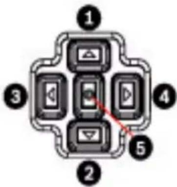
flowchart
graph TD
    A["Device 1"] --> B["Device 2"]
    C["Device 3"] --> D["Device 4"]
    E["Device 5"] --> F["Device 6"]
    G["Device 2"] --> H["Device 3"]
    I["Device 4"] --> J["Device 5"]
Figure 10.1 Advanced camera setup keypad
| Key Description | ||||||
| 1 | U | p | k | e | y | |
| 2 Down key | ||||||
| 3 | L | e | f | t | k | e |
| 4 | R | i | g | h | t | k |
| 5 Menu/Select key | ||||||
y e y
- Use the up or down keys to scroll through a menu.
- Use the left or right keys to move through options or to set parameters.
- When in a menu, quickly double-press the menu/select key to restore the selected item to its factory default.
- To close all menus at once, hold down the menu/select key until the menu display disappears or continually select the Exit item.
Some menus close automatically after about two minutes; other menus must be closed manually.
10.2 Pre-defined modes
There are six pre-defined modes with settings to make configuration easier. You can select one of the six pre-defined modes in the Install/Mode submenu. The modes are defined as follows:
1. 24-hour
Default installation mode to provide stable pictures over a 24-hour period. These settings are optimized for out-of-the-box installation.
2. Traffic
Capture high-speed objects using default shutter in variable lighting conditions.
3. Low light
Provide extra enhancement such as AGC and SensUp to make usable pictures in low-light conditions.
4. Smart BLC
Settings optimized to capture details in high contrast and extremely bright-dark conditions.
5. Low noise
Enhancements are set to reduce picture noise. Useful for conditional refresh DVR and IP storage systems because reducing noise reduces the amount of storage required.
6. Infrared
Settings are configured to provide optimal imaging performance in low-light or no-light conditions.
10.3 Main menu structure
| Item Selection Description | ||
| Mode Submenu | Sets up operating modes 1 to 6 | |
| ALC Submenu Video level control | ||
| Shutter/AGC Submenu Shutter and automatic gain control | ||
| Day/Night Submenu Day/Night for color/mono operation | ||
| Illuminator Submenu Illuminator intensity and control | ||
| Enhance / Dynamic Engine | Submenu | Picture enhancement and performance |
| Color Submenu | White balance and color rendition | |
| VMD Submenu Video motion detection | ||
| EXIT | Closes the main menu | |
10.3.1 Mode submenu
| Item | Selection | Description |
| Mode | 1 to 6 | Selects operating mode. |
| Mode ID | Alphanumeric | Mode name (11 characters maximum) |
| Copy active mode | Available mode numbers | Copies current mode settings to the mode number selected. |
| Default mode | Submenu | Restores camera to the factory default settings. |
| EXIT | Returns to main menu. |
10.3.2 ALC submenu
| Item Selection Description | ||
| ALC level -15 to +15 Selects the range within which the ALC will operate. A positive value is more useful for low-light conditions; a negative value is more useful for very bright conditions. Some ALC adjustment may improve scene content when Smart/BLC is enabled. | ||
| Peak/average -15 to +15 Adjusts the balance between peak and average video control. A negative value gives more priority to average light levels; a positive value gives more priority to peak light levels. Video iris lens: select an average level for best results (peak settings may cause oscillations). | ||
| ALC speed Slow, medium, fast | Adjusts the speed of the video level control loop. For most scenes it should remain at the default value. | |
| DVR/IP Encoder On, Off On - The camera output is optimized for connection to a DVR or IP encoder to compensate for compression methods. Off - The camera output is optimized for connection to an analog system (matrix switcher or monitor). | ||
| EXIT Returns to main menu. | ||
10.3.3 Shutter/AGC submenu
| Item Selection Description | ||
| Shutter AES, FL, Fixed | AES (auto-shutter) | - the camera automatically sets the optimum shutter speed.FL - flickerless mode avoids interference from light sources (recommended for video-iris or DC-iris lenses only).FIXED - allows a user defined shutter speed. |
| Default (AES) shutter or Fixed shutter | 1/50 (PAL), 1/60 (NTSC), 1/100, 1/120, 1/250, 1/500, 1/1000, 1/2000, 1/5000, 1/10K | In AES mode, the camera tries to maintain the selected shutter speed as long as the light level of the scene is high enough.In Fixed mode, selects shutter speed. |
| Actual shutter Displays | the actual shutter value from the camera to help compare lighting levels and optimum shutter speed during set-up. | |
| Gain control On, Fixed | On - the camera | automatically sets the gain to the lowest possible value needed to maintain a good picture.Fixed - sets Fixed AGC value. |
| Maximum AGC or Fixed AGC | 0 to 30 dB Selects | the maximum value that the gain can have during AGC operation.Selects the gain setting for Fixed gain operation (0 is no gain). |
| Actual AGC | Displays the actual AGC value from the camera to help compare gain level with lighting levels and picture performance. | |
| SensUpDynamic | Off, 2x, 3x, ..., 10x | Selects the factor by which the sensitivity of the camera is increased.When active, some noise or spots may appear in the picture.This is normal camera behavior.It may also cause motion blur on moving objects. |
| EXIT Returns to main menu. | ||
10.3.4 Day/Night submenu
| Item Selection Description | ||
| Day/Night Auto Video,AutoPhotocell,Color,Monochrome | Auto Video - the camera switches the IR cut-off filter on and off depending on the scene illumination level detected by the camera video level.Auto Photocell - the camera switches the IR cut-off filter on and off depending on the ambient light level detected by the photocell.Monochrome - the IR cut-off filter is removed, giving full IR sensitivity.Color - the camera always produces a color signal regardless of light levels. | |
| SW Level -15 to +15 Sets the video | or photocell level inAuto mode at which the camera switches to monochrome operation.A low (negative) value means that the camera switches to monochrome at a lower light level.A high (positive) value means that the camera switches to monochrome at a higher light level. | |
| Priority Motion, Color In AUTO mode: | Color - the camera gives a color image as long as the light level permits.Motion - the camera avoids motion blur as long as the light level permits (it switches to monochrome earlier than it would with Color priority). | |
| IR contrast Enhanced, Normal | Enhanced - the camera optimizes contrast in applications with high IR illumination levels. Select this mode for IR (730 to 940 nm) light sources and for scenes with grass and green foliage.Normal - the camera optimizes contrast in mono applications with visible light illumination. | |
| Color burst (mono) | On, Off Off - the color burst in the video signal is switched Off in monochrome mode.On - the color burst remains active even in monochrome mode (required by some DVRs and IP encoders). | |
| EXIT Returns to main menu. | ||
10.3.5 Illuminator submenu
| Item Selection Description | ||
| Illuminator | On, Off, Auto | On - the illuminator is always on, regardless of ambient light level.Off - the illuminator remains off, regardless of ambient light level.Auto - the camera switches the illuminator on and off depending on the Day/Night mode. |
| Intensity | 0 to 30 | Adjusts the intensity of the illuminator light. The default value is 30. |
| EXIT | Returns to main menu. | |
10.3.6 Enhance / Dynamic Engine submenu
| Item Selection Description | ||
| Dynamic Engine | Off, XF-DYN, 2X-DYN*, SmartBLC | Off - turns off all automatic scene detail and enhancements (only recommended for testing).XF-DYN - extra internal processing is enabled for low-light applications (traffic, etc.).2X-DYN - 2X-Dynamic adds dual sensor exposure to the XF-DYN features. In harsh lighting conditions, pixels from each exposure are mixed to give a more detailed image. (Use 2X-DYN when SmartBLC is not required.)SmartBLC - BLC window and weighting factor are defined automatically. Camera adjusts dynamically for changing light conditions. Includes all the benefits of 2X-DYN. |
| Autoblack On, Off | Autoblack On | - increases automatically the visibility of details even when scene contrast is less than full-range due to mist, fog, etc. |
| Black level -50 to | +50 Adjusts th | the black offset level.A low (negative) value makes the level darker. A high (positive) value makes the level lighter and may bring out more detail in the darker areas. |
| Sharpness -15 to | +15 Adjusts th | the sharpness of the picture. 0 corresponds to the default position.A low (negative) value makes the picture less sharp. Increasing sharpness brings out more detail.Extra sharpness can enhance the details of license plates, facial features and the edges of certain surfaces. |
| Dynamic noise reduction | Auto, Off In A | AUTO mode, the camera automatically reduces the noise in the picture.This may cause some motion blur on exceptionally fast moving objects immediately in front of the camera. This can be corrected by widening the field of view or selecting Off. |
| Peak White Invert | On, Off Use P | Peak White Invert to reduce glare from the CRT/LCD display.Use in ANPR/LPR applications to reduce headlight glare. (Test on-site to ensure that it does benefit the application and is not distracting for operators of the security system.) |
| EXIT Returns to main menu. | ||
10.3.7 Color submenu
| Item Selection | Description | |
| White balance | ATW, AWBhold, Manual | ATW - Auto tracking white balance allows the camera to constantly adjust for optimal color reproduction.AWBhold - Puts the ATW on hold and saves the color settings.Manual - the Red, Green, and Blue gain can be set manually to a desired position. |
| Speed Fast, | Medium, Slow | Adjusts the speed of the white balance control loop. |
| Red gain | -5 to +5-50 to +50 | ATW and AWBhold - adjusts the Red gain to optimize the white point.Manual - adjusts the Red gain. |
| Blue gain | -5 to +5-50 to +50 | ATW and AWBhold - adjusts the B gain to optimize the white point.Manual - adjusts the Blue gain. |
| Green gain -50 | to +50 Manual | - adjusts the Green gain. |
| Saturation -15 | to +5 Adjusts the color saturation. -15 gives a monochrome image. | |
| EXIT Returns to main menu. | ||
10.3.8 VMD submenu
| Item Selection Description | ||
| VMD Off, Silent, OSD | Off - Video Motion Detection (VMD) is off.Silent - video motion generates silent alarm.OSD - video motion generates on-screen text message alarm. | |
| VMD Area | Submenu Select to enter the area set-up menu to define the detection area. | |
| Motion indicator | Indicates the peak of measured motion in the selected area. Press either the right, left or center navigation button to reset. | |
| VMD sensitivity | Sets the sensitivity for motion to the desired level. The longer the white bar, the more motion is required to activate the VMD alarm. Motion above this level activates alarm. | |
| OSD alarm text | Alphanumeric | Text for on-screen display alarm (16 characters maximum). |
| EXIT | Returns to main menu. | |
Selecting an area for VMD masking
- From the submenu VMD, select the option "VMD Area."
The submenu VMD Area appears, and the system displays the current area selected. Note that the upper left corner is flashing. - Press Select to 'unlock' the flashing corner.
- Use the arrow keys Up, Down, Left, or Right as needed to move the flashing corner and to set the area for virtual motion detection.
- Press Select again to freeze the area and exit the menu.
Note: There is one programmable VMD area. When VMD is enabled, normal light fluctuations or environmental factors can contribute to false-positive alarms. Because of this, it is
recommended that you do not connect the VMD-triggered alarm output of the camera to a monitored alarm system as the false-positive alarms may be considered a nuisance.
10.4 Install menu structure
| Item Selection Description | ||
| Lens Wizard Sub | menu Select | ct to optimize the camera-lens combination backfocus point. |
| Language Subme | nu Select | on-screen display (OSD) language |
| Privacy Masking | Submenu | Sets up a masking area |
| Synchronization | Submenu | Sets synchronization parameters |
| Alarm Output Sub | bmenu Pro | gram the alarm output functionality. |
| Connections Sub | bmenu Con | nection parameters |
| Test Signals Sub | menu Test | patterns and texts |
| Camera ID Subm | enu Select | to access ID submenu |
| Defaults | Submenu | Returns all settings for all modes to factory defaults |
| EXIT | Closes the Install menu | |
10.4.1 Lens Wizard submenu
| Item | Selection Description | |
| Lens type | Auto, Manual, DC-iris, Video | Auto - automatically selects the type of lens. Manual, DC-iris, Video modes - select the matching lens type to force the camera to the correct lens mode. |
| Detected | Shows the type of lens detected when auto lens detection is used. | |
| Set Backfocus now | Select to fully open the iris. Follow the instructions below for setting the backfocus for your particular lens type. After focusing, the object of interest remains in focus under bright and low light conditions. | |
| Set LVL | Only for video-iris lenses. Adjust the level control on the lens to center the level detector indicator (see below). | |
| EXIT | Returns to Install menu. | |
10.4.2 Language submenu
| Item Selection Description | ||
| Language English | SpanishFrenchGermanPortuguesePolishItalianDutchRussian | Displays the menus on the OSD in the chosen language. |
| EXIT Returns to In | stall menu. | |
10.4.3 Privacy Masking submenu
| Item Selection Description | ||
| Pattern Black, Grey, White, Noise | Selects pattern for all masks. | |
| Mask 1, 2, 3, 4 Four different areas can be masked. | ||
| Active | On, Off | Turns each of the four masks on or off. |
| Window | Submenu | Select to open a window in which to define the mask area. |
| EXIT | Returns to Install menu. | |
Selecting an area for privacy masking
- From the submenu Privacy Masking, select the option "Window." The submenu Window appears, and the system displays the current area selected. Note that the upper left corner is flashing.
- Press Select to 'unlock' the flashing corner.
- Use the arrow keys Up, Down, Left, or Right as needed to move the flashing corner and to set the area for privacy masking.
- Press Select again to freeze the area and exit the menu.
Note: There are four programmable areas for privacy masking.
10.4.4 Synchronization submenu
| Item Selection Description | ||
| Synchronization | InternalLine lock | Internal - for free running camera operation.Line lock - to lock to the AC power supply |
| Horizontal phase | -25 . . 0 . . +25 | Adjusts the horizontal phase offset. |
| Subphase 0, 2 . . | 358 Adjusts the subcarrier phase. | |
| EXIT Returns to In | stall menu. | |
10.4.5 Alarm Output submenu
| Item Selection | Description | |
| Alarm output | VMD,External device,Night mode active,Filter toggle | VMD - output relay closes on VMD alarms.External device - make the output relay available to remote communication devices.Night mode active - output relay closes when camera is in monochrome mode.Filter toggle - output relay closes just before the IR filter starts moving and opens when video level has stabilized (2 to 3 seconds). |
| EXIT Returns | to Install menu. |
10.4.6 Connections submenu
| Item Selection Description | ||
| Notch filter On, | Off Switches not | tch filter on or off. The notchfilter can remove a Moiré pattern or color artifacts caused by closely spaced vertical lines or objects (for example, vertical security bars over windows). |
| Bilinx Comms. On, Off If Off, Bilinx communications is disabled. | ||
| Camera buttons | Enable, disable | Enable or disable the camera buttons from working. |
| Cable compensation | Off, Default, RG59, RG6, Coax12 | Cable compensation is used to avoid the need for amplifiers in long distance coaxial connections up to 1000 m (3000 ft). For optimum results, select the coaxial cable type used or, if unknown, select default. |
| Compensation level | 0,1,2 . . .+15 Sets the level of cable compensation. | |
| EXIT Returns to install menu. | ||
10.4.7 Test Signals submenu
| Item Selection | Description | |
| Show camera ID | Off, On | Select On to overlay the camera ID on the video test signal. |
| Test pattern | Color bars 100%, Grayscale 11-step, Sawtooth 2H, Checker board, Cross hatch, UV plane | Select the desired test pattern to help installation and fault-finding. |
| EXIT | Returns to Install menu. |
10.4.8 Camera ID submenu
| Item Selection Description | ||
| Camera ID Enter a | 17-character ca | camera name. UseLeft/Right to change position in the string; use up/down to select character.Use Select to exit. |
| Display ID pos. Off | Top left,Top right,Bottom left,Bottom right | Selects the screen position of the camera ID. |
| Camera ID border | On, Off Displays | a grey border behind the camera ID to make it easier to read. |
| MAC address Shows MAC address (factory set, cannot be changed). | ||
| Ticker bars On, Off The ticker bar | moves continuously to show that the image is live and not frozen or played back. | |
| Display mode ID Off, Top left,Top right,Bottom left,Bottom right | Displays the camera mode in the selected position on the screen. | |
| EXIT Returns to Install menu. | ||
10.4.9 Defaults submenu
| Item Selection Description | ||
| Restore All | No, Yes | Restores all settings of the six modes to their default (factory) values. Select YES, then press the Menu/Select button to restore all values.When completed, the message RESTORED! appears. |
| EXIT | Returns to Install menu. | |
11 Maintenance
11.1 Repairs
DANGER!
Disconnect power before servicing or disassembling the housing or unit.

CAUTION!
Never open the casing of the camera. The unit does not contain any user-serviceable parts. Ensure that all maintenance or repair work is performed only by qualified personnel (electrical engineering or network technology specialists). If in doubt, contact your dealer's technical service center.
11.2 Transfer and Disposal
The unit should only be passed-on together with this installation guide. The unit contains environmentally hazardous materials that must be disposed of according to law. Defective or superfluous devices and parts should be disposed of professionally or taken to your local collection point for hazardous materials.
12 Technical Data
NEI-30 Models
| Model Number Description Rated | Voltage | Rated Frequency | |
| NEI-308V05-13WE | EX30CR IP, 850nm, PAL | 12 VDC/24 VAC (±10%) | 50 Hz |
| NEI-308V05-23WE | EX30CR IP, 850nm, NTSC | 12 VDC/24 VAC (±10%) | 60 Hz |
| NEI-309V05-13WE | EX30CR IP, 940nm, PAL | 12 VDC/24 VAC (±10%) | 50 Hz |
| NEI-309V05-23WE | EX30CR IP, 940nm, NTSC | 12 VDC/24 VAC (±10%) | 60 Hz |
Electrical
| Power Consumption | |
| at 12 VDC 35 W (2.9 A) | |
| at 24 VAC 35 W (1.5 A) | |
Video
| CCD Type 1/3 in. interline, WDR dual shutter | |
| Active Pixels PAL models: 752 x 582 | |
| Horizontal Resolution 540 TVL | |
| Signal-to-Noise Ratio (SNR) > 50 dB | |
| Video Output Composite Video 1 Vpp, 75 Ohm |
Mechanical
| Dimensions (HxWxL), Camera and Bracket | 402 mm x 193 mm x 309 mm(15.8 in. x 7.6 in. x 12.2 in.) |
| Dimensions (HxWxL), Total Assembly | 402 mm x 193 mm x 406 mm(15.8 in. x 7.6 in. x 16.2 in.) |
| Weight, Camera and Bracket | 6.6 kg (14.55 lbs) |
| Weight, Junction Box | 1.4 kg (3.5 lbs) |
| Construction | Corrosion-resistant aluminum |
| Color | White (RAL 9010) with black(RAL 9005) detail |
| Finish Wet paint | |
| Window 3.3 mm (1/8-in.) thick glass | |
| Bracket Corrosion-resistant, cable-managed | |
| Bracket Pan/Tilt Range | Pan: ±90° (180° total)Tilt: -48° / +44° (92° total) |
| Junction Box Separate | from bracket to allow for wiring and cabling prior to camera installation |
Environmental
| Operating Temperature, Standard (Warm-up period required for cold start at-40 °C/°F.) | -40 °C to +50 °C (-40 °F to 122 °F) |
| Operating Temperature with POE+ (Warm-up period required for cold start at-40 °C/°F.) | -20 °C to +50 °C (-4 °F to 122 °F) |
| Storage Temperature -40 °C to +70 °C (-40 °F to 158 °F) | |
| Operating Humidity 20% to 100% (condensing) | |
| Storage Humidity up to 100% | |
| Wind load, operational 145 kph (90 mph) (sustained) | |
| Wind load, non-operational Gusts up to 260 kph (155 mph) | |
Index
A
accessing controls 30
activation key 97
AES 57
AGC 57
alarm 52
alarm e-mail 84
alarm message 53
alarm sensors 71, 72
ALC 57
attaching
pendant arm 27
auto-connect 77
B
basic mode 41
blue gain 61
Browser window 38
C
cable
Ethernet 28
camera
selection 40
camera name 48
changes in light level 80
configuration 30, 37
configuration download 96
configuration mode 40
connect on alarm 74
connect to PC 28
control data I/O plug 25
D
date 50
date format 50
day/night 58
daylight saving time 50
default profile 64
default recording profile 70
default VCA profile 77
deleting recordings 69
device ID 48
Device name 48
device name 43
DHCP server 45
Dibos 36
DirectX 36
display stamping 51
disposal 115
dual Streaming 61
dual streaming 15
dynamic engine 60
dynamic noise reduction 60
DynDNS 90
E
e-mail 84
encoder 46, 61
encoding 15
video 15
encryption protocol 88
EPROM 96
ethernet 28
event log 39, 54, 55
F
false alarms 80
files
JPEG 15
MPEG-4 36
firewall 76, 88
firmware upload 95
formatting 69
frame rate 63, 65, 72
FTP server 94, 95
G
gain 58
gateway 46, 88
gateway address 37
general password 75
green gain 60
H
holidays 73
HTTP port 88
HTTPS port 88
|
Identification 48
identification 43
IEEE 802.1x 91
IGMP 93
IGMP V2 15
Illuminator 59
image quality 94
image resolution 40
image selection 40
initiator name 49
installation 22
internal clock 50
IP 28
address 37, 45
alarm 38
dual streaming 15
encoding 15
gateway address 37
module 28
multicast 15
port 37
record 15
snapshots 15
subnet mask 37
system requirements 36
IP address 87
IR contrast 59
iSCSI settings 67
J
JPEG 15
JPEG posting 94
JPEG posting interval 95
L
language 53
licenses 97
LIVEPAGE 38, 54
livepage 54
logging 55
M
maintenance 115
manufacturer logo 53
menu navigation 98
milliseconds 52
modes 56
motion detector 77
motion detector defaults 77
motion detector object size 80
motion detector sensitivity 80, 81
mounting 19, 22
MPEG ActiveX 36
MPEG-4 36
MTU value 88, 89
multicast 15
multicast address 93
multicast connection 88, 93
multicasting 92
multi-unicast 92
N
navigation 41
NEMA Certification
for pendant arm, corner or mast mount 20, 24
network 45, 87, 90
networking
Ethernet cable 28
gateway address 37
IGMP V2 15
IP 28
IP address 37
port 37
subnet mask 37
TCP/IP 28
UDP 15
number of connections 42
0
operation modes 56, 99
P
parts list 16, 18
password 42, 43, 49
peak white invert 60
pendant arm
attaching to power supply box 27
polarity 25
port 37, 88, 94
post-alarm profile 71
post-alarm time 71
power supply box
attaching to pendant arm 27
pre-alarm time 71
privacy masking 65
product name 53
profile configuration 61
profiles 46, 61
protocol
IGMP V2 15
TCP/IP 28
UDP 15
R
RADIUS 91
receiver password 75
record 15
recording media 67
recording profiles 69
recording scheduler 72
recording status 74
recording video sequences 40
red gain 60
reflections of light 80
retention time 72
router 94
S
saturation 61
saving event log 55
saving snapshots 39
saving system log 55
savng configuration 96
select area 80, 83
selecting a profile 61
sensor fields 80, 83
shutter 57
snapshots 15, 39
SNMP 91
SNTP server 45, 51
software
DirectX 36
SSL certificate 96
SSL encryption 76
standard recording profile values 70
storage media 68
storage medium 46
streaming 94
subnet mask 37, 46, 87
summer time 50
synchronization 66
synchronize 44, 50
system log 39, 55, 56
T
tamper detection 81
target data rate 62
TCP 76, 88
TCP/IP 28
time 44, 50, 52
time server 44, 51
IP address 45
protocol 44
time server IP address 51
time server protocol 51
time signal 44, 51
time zone 50
TLS 88
transmission protocol 76, 88
traps 91
TTL 94
U
UDP 15, 76, 88
unicast 92
unit date 50
Unit identification 48
unit identification 43
Unit name 48
unit name 43
unit time 44, 50
user name 43, 49
V
video content analysis 77
video sensor 77
VIDOS 36
VIP XD 36
VRM 67
W
watermarking 53
white balance 60
wiring
for pendant arm, corner or mast mount 20
Bosch Security Systems, Inc.
850 Greenfield Road
Lancaster, PA 17601
U.S.A.
www.boschsecurity.com
© Bosch Security Systems, Inc., 2012