AutoDome VG5-162 - Security Camera BOSCH - Free user manual and instructions
Find the device manual for free AutoDome VG5-162 BOSCH in PDF.

User questions about AutoDome VG5-162 BOSCH
0 question about this device. Answer the ones you know or ask your own.
Ask a new question about this device
Download the instructions for your Security Camera in PDF format for free! Find your manual AutoDome VG5-162 - BOSCH and take your electronic device back in hand. On this page are published all the documents necessary for the use of your device. AutoDome VG5-162 by BOSCH.
USER MANUAL AutoDome VG5-162 BOSCH
natural_image
Three white security cameras mounted on a wall, showing different camera designs (no text or symbols visible)AutoDome 100 Series Fixed Camera
AutoDome 100 Series

BOSCH
en Installation Manual
Table of Contents
| 1 | S | a | f | e | t | y | 6 |
1.1 Important Safety Instructions 6
1.2 Safety Precautions 8
1.3 Important Notices 8
1.4 Customer Support and Service 12
2 Installing the Pendant Arm Wall, Corner, and Mast (Pole) Mounts 13
| 2.1 Unpacking | 13 | |
| 2.1.1 | Parts List | 13 |
| 2.1.2 | Description | 14 |
| 2.1.3 | Tools Required | 14 |
| 2.2 Pre-installation Checklist | 14 | |
| 2.3 Mount Power Supply Box | 15 | |
| 2.4 Route Wires and Attach Connectors | 16 | |
| 2.4.1 | Make the Connections | 17 |
| 2.4.2 | Power Supply Box Connections | 19 |
| 2.5 | Route Power through Intermediate Power Supply Box | 20 |
| 2.6 Attach Pendant Arm to Power Supply Box | 23 | |
| 2.7 Make Connections in Power Supply Box | 24 | |
| 2.8 Installing the VG4-A-ARMPLATE | 26 | |
| 2.8.1 | Attach the Pendant Arm to the Mounting Plate | 27 |
| 2.8.2 | Route and Connect Wires to a Power Supply Box | 28 |
| 2.9 Attach Pendant to Arm and Tighten | 31 | |
3 Installing Roof Parapet and Pipe Mounts 33
| 3.1 Unpacking | 33 | |
| 3.1.1 | Parts List | 33 |
| 3.1.2 | Description | 33 |
| 3.1.3 | Tools Required | 34 |
| 3.2 Pre-installation Check List | 34 | |
| 3.3 Mount Power Supply Box | 35 | |
| 3.3.1 | Attach Cover Door | 36 |
| 3.4 Route Wires and Attach Connectors | 37 | |
| 3.4.1 | Methods for Routing Wires | 37 |
| 3.4.2 | Wiring the Power Supply Box | 39 |
| 3.4.3 | Wiring the Fiber Optic Model | 39 |
| 3.4.4 | Power Supply Box Connections | 41 |
| 3.5 Installing the VG4-A-9230 Roof Parapet Mount | 42 | |
| 3.6 Installing the VG4-A-9543 Pipe Mount | 45 | |
| 3.7 Wire the Pipe Interface Board | 46 | |
| 3.7.1 | Wiring for Multiple AutoDomes 47 | |
| 3.7.2 | Connecting Wires to the Pipe Interface Board | 48 |
| 3.8 Attach Pendant to Pipe and Tighten | 50 | |
| 3.9 Make Connections in the Power Supply Box | 51 | |
| 3.9.1 | Connections for Fiber Optic Models | 51 |
4 Installing the In-Ceiling Mount 52
4.1 Unpacking 52
4.1.1 Parts List 52
4.1.2 Description 52
4.1.3 Tools Required 52
4.2 Pre-installation Check List 52
4.3 Dimensions 53
4.4 Prepare Drywall Ceiling for Installation 53
4.5 Prepare Suspension Ceiling for Installation 54
4.6 Wire the Interface Box 55
4.6.1 Make the Connections 56
4.6.2 Interface Box Connections 57
4.7 Attach Housing to the Interface Box 58
4.8 Secure Housing to Ceiling 60
5 Cable and Wire Standards 61
5.1 Power 61
5.2 Wire Distance Guide for Pendant 61
5.3 Video and Control Cables 61
5.3.1 Using Coaxial Cable to Transmit Video and Control 61
5.3.2 Using UTP to Transmit Video and Control 62
5.3.3 Using Multi-mode Fiber Optic to Transmit Video and Control 62
5.4 Control-only Cables 63
5.4.1 Controlling the AutoDome via Biphase 63
5.4.2 Controlling the AutoDome via the RS232 Protocol 64
5.4.3 Controlling the AutoDome via the RS485 Protocol 65
5.5 Fiber Optic Module with an RS232/RS422 Controller 67
5.5.1 Connecting to an LTC 4629 Head End Data/Video Transceiver 67
5.5.2 Configuring the VG5 AutoDome 67
6 Alarms and Relay Connections 69
6.1 Alarm Inputs 69
6.2 Configuring Supervised Alarms (inputs 1 and 2) 69
6.2.1 Configuring a Normally Open Supervised Alarm 69
6.2.2 Configuring a Normally Closed Supervised Alarm 70
6.3 Configuring Non-supervised Alarms (inputs 1 through 7) 70
6.3.1 Configuring a Normally Open Non-supervised Alarm 71
6.3.2 Configuring a Normally Closed Non-supervised Alarm 71
6.4 Alarm Outputs 72
6.4.1 Configuring a Dry Contact Relay 72
6.4.2 Configuring an Open Collector Output 72
7 Bubble Handling and Cleaning 73
7.1 Handling 73
7.2 Cleaning 73
7.2.1 Cleaning the Bubble Interior 73
7.2.2 Cleaning the Bubble Exterior 74
Index
75
1 S a f e t
1.1 Important Safety Instructions
Read, follow, and retain for future reference all of the following safety instructions. Heed all warnings on the unit and in the operating instructions before operating the unit.
- Cleaning - Unplug the unit from the outlet before cleaning. Follow any instructions provided with the unit. Generally, using a dry cloth for cleaning is sufficient, but a moist fluff-free cloth or leather shammy may also be used. Do not use liquid cleaners or aerosol cleaners.
- Heat Sources - Do not install the unit near any heat sources such as radiators, heaters, stoves, or other equipment (including amplifiers) that produce heat.
- Ventilation - Any openings in the unit enclosure are provided for ventilation to prevent overheating and ensure reliable operation. Do not block or cover these openings. Do not place the unit in an enclosure unless proper ventilation is provided, or the manufacturer's instructions have been adhered to.
- Water - Do not use this unit near water, for example near a bathtub, washbowl, sink, laundry basket, in a damp or wet basement, near a swimming pool, in an outdoor installation, or in any area classified as a wet location. To reduce the risk of fire or electrical shock, do not expose this unit to rain or moisture.
- Object and liquid entry - Never push objects of any kind into this unit through openings as they may touch dangerous voltage points or short-out parts that could result in a fire or electrical shock. Never spill liquid of any kind on the unit. Do not place objects filled with liquids, such as vases or cups, on the unit.
- Lightning - For added protection during a lightning storm, or when leaving this unit unattended and unused for long periods, unplug the unit from the wall outlet and disconnect the cable system. This will prevent damage to the unit from lightning and power line surges.
- Controls adjustment - Adjust only those controls specified in the operating instructions. Improper adjustment of other controls may cause damage to the unit. Use of controls or adjustments, or performance of procedures other than those specified, may result in hazardous radiation exposure.
- Overloading - Do not overload outlets and extension cords. This can cause fire or electrical shock.
- Power cord and plug protection - Protect the plug and power cord from foot traffic, being pinched by items placed upon or against them at electrical outlets, and its exit from the unit. For units intended to operate with 230 VAC, 50 Hz, the input and output power cord must comply with the latest versions of IEC Publication 227 or IEC Publication 245.
-
Power disconnect · Units with or without ON/OFF switches have power supplied to the unit whenever the power cord is inserted into the power source; however, the unit is operational only when the ON/OFF switch is in the ON position. The power cord is the main power disconnect device for switching off the voltage for all units.
-
Power sources · Operate the unit only from the type of power source indicated on the label. Before proceeding, be sure to disconnect the power from the cable to be installed into the unit.
-
For battery powered units, refer to the operating instructions.
- For external power supplied units, use only the recommended or approved power supplies.
- For limited power source units, this power source must comply with EN60950. Substitutions may damage the unit or cause fire or shock.
- For 24 VAC units, voltage applied to the unit's power input should not exceed ± 10% , or 28 VAC. User-supplied wiring must comply with local electrical codes (Class 2 power levels). Do not ground the supply at the terminals or at the unit's power supply terminals.
- If unsure of the type of power supply to use, contact your dealer or local power company.
- Servicing - Do not attempt to service this unit yourself. Opening or removing covers may expose you to dangerous voltage or other hazards. Refer all servicing to qualified service personnel.
- Damage requiring service - Unplug the unit from the main AC power source and refer servicing to qualified service personnel when any damage to the equipment has occurred, such as:
- the power supply cord or plug is damaged;
- exposure to moisture, water, and/or inclement weather (rain, snow, etc.);
– liquid has been spilled in or on the equipment;
- an object has fallen into the unit;
- unit has been dropped or the unit cabinet is damaged;
- unit exhibits a distinct change in performance;
- unit does not operate normally when the user correctly follows the operating instructions.
-
Replacement parts - Be sure the service technician uses replacement parts specified by the manufacturer, or that have the same characteristics as the original parts. Unauthorized substitutions may cause fire, electrical shock, or other hazards.
-
Safety check - Safety checks should be performed upon completion of service or repairs to the unit to ensure proper operating condition.
-
Installation · Install in accordance with the manufacturer's instructions and in accordance with applicable local codes.
-
Attachments, changes or modifications - Only use attachments/accessories specified by the manufacturer. Any change or modification of the equipment, not expressly approved by Bosch, could void the warranty or, in the case of an authorization agreement, authority to operate the equipment.
1.2 Safety Precautions
DANGER!
This symbol indicates an imminently hazardous situation such as “Dangerous Voltage” inside the product. If not avoided, this will result in an electrical shock, serious bodily injury, or death.

WARNING!
Indicates a potentially hazardous situation. If not avoided, this could result in serious bodily injury or death.
CAUTION!
Indicates a potentially hazardous situation. If not avoided, this may result in minor or moderate injury. Alerts the user to important instructions accompanying the unit.

CAUTION!
Indicates a potentially hazardous situation. If not avoided, this may result in property damage or risk of damage to the unit.

NOTICE!
This symbol indicates information or a company policy that relates directly or indirectly to the safety of personnel or protection of property.
1.3 Important Notices

natural_image
Silhouette of a person climbing a ladder inside a circular frame (no text or symbols)Accessories - Do not place this unit on an unstable stand, tripod, bracket, or mount. The unit may fall, causing serious injury and/or serious damage to the unit. Use only with the cart, stand, tripod, bracket, or table specified by the manufacturer. When a cart is used, use caution and care when moving the cart/apparatus combination to avoid injury from tip-over. Quick stops, excessive force, or uneven surfaces may cause the cart/unit combination to overturn. Mount the unit per the manufacturer's instructions.
All-pole power switch · Incorporate an all-pole power switch, with a contact separation of at least 3 mm in each pole, into the electrical installation of the building. If it is needed to open the housing for servicing and/or other activities, use this all-pole switch as the main disconnect device for switching off the voltage to the unit.
Camera grounding - For mounting the camera in potentially damp environments, ensure to ground the system using the ground connection of the power supply connector (see section: Connecting external power supply).
Camera lens - An assembled camera lens in the outdoor housing must comply and be tested in accordance with UL/IEC60950. Any output or signal lines from the camera must be SELV or Limited Power Source. For safety reasons the environmental specification of the camera lens assembly must be within the environmental specification of -10^ (14°F) to 50^ (122°F).
Camera signal - Protect the cable with a primary protector if the camera signal is beyond 140 feet, in accordance with NEC800 (CEC Section 60).
Coax grounding:
- Ground the cable system if connecting an outside cable system to the unit.
- Connect outdoor equipment to the unit's inputs only after this unit has had its grounding plug connected to a grounded outlet or its ground terminal is properly connected to a ground source.
- Disconnect the unit's input connectors from outdoor equipment before disconnecting the grounding plug or grounding terminal.
- Follow proper safety precautions such as grounding for any outdoor device connected to this unit.
U.S.A. models only - Section 810 of the National Electrical Code, ANSI/NFPA No.70, provides information regarding proper grounding of the mount and supporting structure, grounding of the coax to a discharge unit, size of grounding conductors, location of discharge unit, connection to grounding electrodes, and requirements for the grounding electrode.

NOTICE!
This device is intended for use in public areas only.
U.S. federal law strictly prohibits surreptitious recording of oral communications.

Your Bosch product was developed and manufactured with high-quality material and components that can be recycled and reused. This symbol means that electronic and electrical appliances, which have reached the end of their working life, must be collected and disposed of separately from household waste material. Separate collecting systems are usually in place for disused electronic and electrical products. Please dispose of these units at an environmentally compatible recycling facility, per European Directive 2002/96/EC.
Environmental statement - Bosch has a strong commitment towards the environment. This unit has been designed to respect the environment as much as possible.
Electrostatic-sensitive device - Use proper CMOS/MOS-FET handling precautions to avoid electrostatic discharge.
NOTE: Wear required grounded wrist straps and observe proper ESD safety precautions when handling the electrostatic-sensitive printed circuit boards.
Fuse rating - For security protection of the device, the branch circuit protection must be secured with a maximum fuse rating of 16A. This must be in accordance with NEC800 (CEC Section 60).
Grounding and polarization - This unit may be equipped with a polarized alternating current line plug (a plug with one blade wider than the other blade). This safety feature allows the plug to fit into the power outlet in only one way. If unable to insert the plug fully into the outlet, contact a locally certified electrician to replace the obsolete outlet. Do not defeat the safety purpose of the polarized plug.
Alternately, this unit may be equipped with a 3-pole grounding plug (a plug with a third pin for earth grounding). This safety feature allows the plug to fit into a grounded power outlet only. If unable to insert the plug into the outlet, contact a locally certified electrician to replace the obsolete outlet. Do not defeat the safety purpose of the grounding plug.
Moving - Disconnect the power before moving the unit. Move the unit with care. Excessive force or shock may damage the unit and the hard disk drives.
Outdoor signals • The installation for outdoor signals, especially regarding clearance from power and lightning conductors and transient protection, must be in accordance with NEC725 and NEC800 (CEC Rule 16-224 and CEC Section 60).
Permanently connected equipment - Incorporate a readily accessible disconnect device in the building installation wiring.
Pluggable equipment - Install the socket outlet near the equipment so it is easily accessible.
PoE - Never supply power via the Ethernet connection (PoE) when power is already supplied via the power connector.
Power disconnect - Units have power supplied whenever the power cord is inserted into the power source. The power cord is the main power disconnect for all units.
Power lines · Do not locate the camera near overhead power lines, power circuits, or electrical lights, nor where it may contact such power lines, circuits, or lights.
SELV
All the input/output ports are Safety Extra Low Voltage (SELV) circuits. SELV circuits should only be connected to other SELV circuits.
Because the ISDN circuits are treated like telephone-network voltage, avoid connecting the SELV circuit to the Telephone Network Voltage (TNV) circuits.
Video loss - Video loss is inherent to digital video recording; therefore, Bosch Security Systems cannot be held liable for any damage that results from missing video information. To minimize the risk of lost digital information, Bosch Security Systems recommends multiple, redundant recording systems, and a procedure to back up all analog and digital information.

NOTICE!
This is a class A product. In a domestic environment this product may cause radio interference, in which case the user may be required to take adequate measures.
FCC & ICES INFORMATION
(U.S.A. and Canadian Models Only, CLASS A)
This device complies with part 15 of the FCC Rules. Operation is subject to the following conditions:
- this device may not cause harmful interference, and
- this device must accept any interference received, including interference that may cause undesired operation.
Note
This equipment has been tested and found to comply with the limits for a Class A digital device, pursuant to Part 15 of the FCC Rules and ICES-003 of Industry Canada. These limits are designed to provide reasonable protection against harmful interference when the equipment is operated in a commercial environment. This equipment generates, uses, and radiates radio frequency energy and, if not installed and used in accordance with the instruction manual, may cause harmful interference to radio communications. Operation of this equipment in a residential area is likely to cause harmful interference, in which case the user will be required to correct the interference at his expense.
Intentional or unintentional modifications, not expressly approved by the party responsible for compliance, shall not be made. Any such modifications could void the user's authority to operate the equipment. If necessary, the user should consult the dealer or an experienced radio/television technician for corrective action.
The user may find the following booklet, prepared by the Federal Communications Commission, helpful: How to Identify and Resolve Radio-TV Interference Problems. This booklet is available from the U.S. Government Printing Office, Washington, DC 20402, Stock No. 004-000-00345-4.
INFORMATIONS FCC ET ICES (commercial applications)
Underwriter Laboratories Inc. ("UL") has not tested the performance or reliability of the security or signaling aspects of this product. UL has only tested fire, shock and/or casualty hazards as outlined in UL's Standard(s) for Safety for Information Technology Equipment, UL 60950-1. UL Certification does not cover the performance or reliability of the security or signaling aspects of this product.
UL MAKES NO REPRESENTATIONS, WARRANTIES, OR CERTIFICATIONS WHATSOEVER REGARDING THE PERFORMANCE OR RELIABILITY OF ANY SECURITY OR SIGNALING-RELATED FUNCTIONS OF THIS PRODUCT.
Copyright
This user guide is the intellectual property of Bosch Security Systems, Inc. and is protected by copyright.
All rights reserved.
Trademarks
All hardware and software product names used in this document are likely to be registered trademarks and must be treated accordingly.

NOTICE!
This user guide has been compiled with great care and the information it contains has been thoroughly verified. The text was complete and correct at the time of printing. The ongoing development of the products may mean that the content of the user guide can change without notice. Bosch Security Systems accepts no liability for damage resulting directly or indirectly from faults, incompleteness or discrepancies between the user guide and the product described.
1.4 Customer Support and Service
If this unit needs service, contact the nearest Bosch Security Systems Service Center for authorization to return and shipping instructions.
Service Centers
USA
Telephone: 800-366-2283 or 585-340-4162
Fax: 800-366-1329
Email: cctv.repair@us.bosch.com
Customer Service
Telephone: 888-289-0096
Fax: 585-223-9180
Email: security.sales@us.bosch.com
Technical Support
Telephone: 800-326-1450
Fax: 585-223-3508 or 717-735-6560
Email: technical.support@us.bosch.com
Repair Center
Telephone: 585-421-4220
Fax: 585-223-9180 or 717-735-6561
Email: security.repair@us.bosch.com
Canada
Telephone: 514-738-2434
Fax: 514-738-8480
Europe, Middle East & Asia Pacific Region
Please contact your local distributor or Bosch sales office. Use this link:
http://www.boschsecurity.com/startpage/html/europe.htm
Europe, Middle East & Asia Pacific Region
Please contact your local distributor or Bosch sales office. Use this link:
http://www.boschsecurity.com/startpage/html/asia_pacific.htm
More Information
For more information please contact the nearest Bosch Security Systems location or visit www.boschsecurity.com
2 Installing the Pendant Arm Wall, Corner, and Mast (Pole) Mounts
2.1 Unpacking
This equipment should be unpacked and handled with care. If an item appears to have been damaged in shipment, notify the shipper immediately.
Verify that all the parts listed in the Parts List below are included. If any items are missing, notify your Bosch Security Systems Sales or Customer Service Representative. Refer to Section 1.4 Customer Support and Service, page 12, for contact information.
The original packing carton is the safest container in which to transport the unit and must be used if returning the unit for service. Save it for possible future use.
2.1.1 Parts List
The following table lists the optional parts you may need for attaching a Pendant to the Arm Wall, Corner, or Mast mount packages.
| Mounting Options Part Numbers | |
| Pendant Arm (Only) VG4-S-ARM | |
| Pendant Arm with Mounting Plate(24 V VG5 models only, no power supply box) | VG4-A-ARMPLATE |
| Pendant Arm with one of the following Power Supply Boxes: | |
| – Power Box without transformer (24 VAC) VG4-A-PA0 | |
| – Power Box with 120 VAC transformeror with 230 VAC transformer | VG4-A-PA1VG4-A-PA2 |
| – Power Box without transformer with Fiber Optic Module (24 VAC) VG4-A-PA0F | |
| – Power Box with 120 VAC transformer and Fiber Optic Moduleor with 230 VAC transformer and Fiber Optic Module | VG4-A-PA1FVG4-A-PA2F |
| Trim Skirt for Power Supply Box (optional) VG4-A-TSKIRT | |
| Corner Mount Kit | |
| – Corner Mount Plate VG4-A-9542 | |
| Mast (Pole) Mount Kit | |
| – Mast Mount Plate | VG4-A-9541 |
2.1.2 Description
Chapter 2 details how to install an AutoDome Pendant Arm to a wall, a corner, or to a mast (pole). Any variations to the installation procedures are noted.
Refer to Section 3 Installing Roof Parapet and Pipe Mounts for a Roof (Parapet) or Pipe mount installation or Section 4 Installing the In-Ceiling Mount for an In-Ceiling mount installation.
2.1.3 Tools Required
- 5 mm Allen wrench (supplied)
- Small, straight-blade screwdriver - 2.5 mm (0.1 in.)
- No. 2 Phillips screwdriver
- Socket wrench and 9/16-in. socket
- Banding tool (Bosch P/N TC9311PM3T) - if installing a mast (pole) mount
- 3/4 in. (20-mm) NPS right angle conduit connector - if installing a mast (pole) mount with a VG4-ARMPLATE
2.2 Pre-installation Checklist
- Determine the location and distance for the Power Supply Box based on its voltage and current consumption.
You may choose to route the main power supply through an intermediate VG4 power supply box (VG4-PSU1 or VG4-PSU2) before connecting the power to the pendant arm power supply box (VG4-PA0). Refer to Section 5 Cable and Wire Standards, page 61, for wiring information and distances. - Use only UL listed liquid tight strain reliefs for conduits to the Power Supply Box to ensure that water cannot enter the box. You must use water tight conduits and fittings to meet NEMA 4 standards.

WARNING!
Power and I/O cabling must be routed separately inside different permanently earthed metal conduits.
-
Route all rough wiring including: power, control, video coax, alarms I/O, relay I/O, and fiber optic cabling. Refer to Section 5 Cable and Wire Standards, page 61, for video and control protocol methods.
-
If you plan to use the RS232 or RS485 protocol to control the AutoDome, refer to Section 5.4.2 Controlling the AutoDome via the RS232 Protocol, page 64, or to Section 5.4.3 Controlling the AutoDome via the RS485 Protocol, page 65, for instructions on configuring the AutoDome to accept these protocols.

WARNING!
Install external interconnecting cables in accordance to NEC, ANSI/NFPA70 (for US application) and Canadian Electrical Code, Part I, CSA C22.1 (for CAN application) and in accordance to local country codes for all other countries.
Branch circuit protection incorporating a 20 A, 2-pole Listed Circuit Breaker or Branch Rated Fuses are required as part of the building installation. A readily accessible 2-pole disconnect device with a contact separation of at least 3 mm must be incorporated.
-
Choose the appropriate AutoDome model (indoor or outdoor) for the environment in which it will be used.
-
Choose the appropriate mounting kit to use, depending on the location of the AutoDome, either wall mount, corner mount, or mast (pole) mount.
If you application contains a Power Supply Box, refer to Section 2.3 Mount Power Supply Box, page 15.
If you are using the Mounting Plate with a 24 V VG5 AutoDome, refer to Section 2.8 Installing the VG4-A-ARMPLATE, page 26.

CAUTION!
Select a rigid mounting location to prevent excessive vibration to the AutoDome camera.
2.3 Mount Power Supply Box
Before mounting the Power Supply Box decide if you should wire the box through the holes in the bottom or back of the box. If wiring the box through the back, move the two (2) seal plugs to the bottom through the holes before mounting.

NOTICE!
Use 3/4-inch (20-mm) NPS fittings for the holes on the bottom and back of the box. Use 1/2-inch (15-mm) NPS fittings for the side holes.
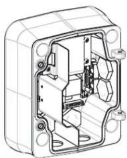
natural_image
Technical line drawing of an internal electrical enclosure or housing with mounting holes and internal components (no text or symbols)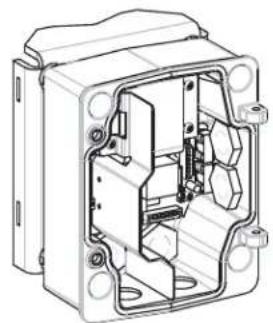
natural_image
Technical line drawing of an open electrical enclosure with internal components (no text or symbols)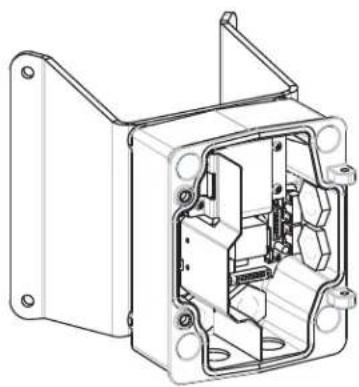
natural_image
Technical line drawing of an internal electrical enclosure or housing frame (no text or symbols)Figure 2.1 Power Supply Wall, Mast (Pole), and Corner Mounts
-
Use the wall mount template supplied in the packaging box to locate the four (4) mounting holes for the Power Supply Box.
-
Drill four (4) holes for the mounting anchors. If installing outdoors, apply a weatherproof sealant around each hole at the mounting surface.

WARNING!
A stud diameter of 6.4 mm (1/4 inch) to 8 mm (5/16 inch) able to withstand a 120 kg (265 lb) pull-out force is recommended. The mounting material must be able to withstand this pull out force. For example, 19-mm (3/4-inch) minimum for plywood.
-
Place the Power Supply Box into the optional Trim Skirt.
-
Secure the Power Supply Box to the mounting surface.
-
For a Wall installation: Use four (4) corrosion-resistant, stainless steel studs (not supplied). Then proceed to Step 5 below.
- For a Corner installation: Secure the Corner Plate to the wall corner using four (4) studs (not included). Then proceed to Step 5 below.
-
For a Mast or a pole installation: The metal straps included with the Mast mount accommodate a pole with a diameter of 100–380 mm (4–15 in.). You must use a banding tool (sold separately) for a mast or pole installation. Follow the instructions provided with the banding tool to securely mount the Mast Plate to the pole. Contact your Bosch Sales Representative to order Banding Tool P/N TC9311PM3T.
-
Secure the Power Supply Box to the Corner Plate or Mast Plate using the four (4) 3/8 x 1-3/4-inch bolts and split lock washers (supplied).
-
Attach 3/4-inch (20-mm) NPS watertight pipe fittings (not supplied) to the bottom or back holes of the Power Supply Box through which you will run the power, video, and control data wires.
2.4 Route Wires and Attach Connectors
Power wires must be routed to the left (front) side of the Power Supply Box through a separate conduit. All video, control, and alarm wires must be routed through a second conduit to the right side of the box.
If you plan to route the power through an intermediate power supply box, refer to Section 2.5 Route Power through Intermediate Power Supply Box, page 20.

WARNING!
External interconnecting cables are to be installed in accordance to NEC, ANSI/NFPA70 (for US application) and Canadian Electrical Code, Part I, CSA C22.1 (for CAN application) and in accordance to local country codes for all other countries.
Branch circuit protection incorporating a 20 A, 2-pole Listed Circuit Breaker or Branch Rated Fuses are required as part of the building installation. A readily accessible 2-pole disconnect device with a contact separation of at least 3 mm must be incorporated.
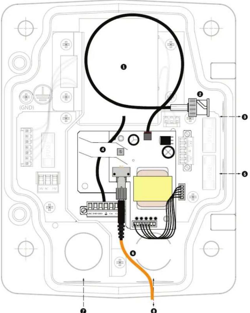
2.4.1 Make the Connections

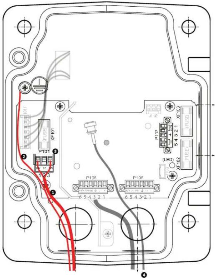
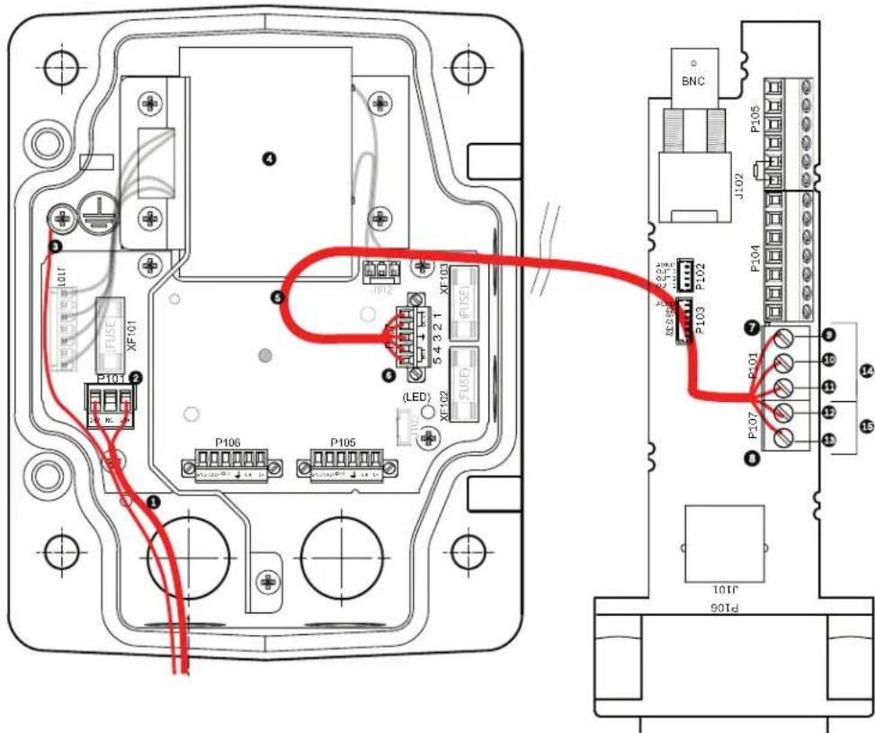
text_image
Technical diagram of an electronic device with labeled ports, connectors, and red wiring connectionsFigure 2.2 Pendant Arm Power Supply Box
- Route all video, control, and alarm wires through the conduit fitting on the right side of the power box. Refer to Section 5 Cable and Wire Standards, page 61, for coax, UTP, Ethernet, and fiber optic specifications and distances.
- Route the high voltage 115/230 VAC lines through the conduit fitting on the left side of the box. The Power Supply Box with a transformer comes with a barrier that separates the high voltage side on the left, from the low voltage 24 VAC side on the right.
- Cut and trim all wires with sufficient slack to reach their connector terminals in the box, but not so long as to be pinched by or to obstruct closing the Pendant Arm. Refer to Figure 2.2, Page 17, above, for the connector locations.
- Attach the supplied 3-pin Power Plug to the incoming power wires. Refer to connector P101 in Table 2.1, Page 20, for wire connections.
- Attach the supplied 6-pin Control Data I/O Plug to the incoming control wires. Refer to connector P106 in Table 2.1, Page 20, for wire connections. This step is not required with Fiber Optic models, since control passes through the fiber optic cable.

NOTICE!
If “daisy chaining” a series of AutoDomes, a terminating resistor is required in the last dome of the series. The Bosch Power Supply Box is supplied with a 100 Ω terminating resistor located between the Biphas terminal C- and C+ (pins 1 and 2) of the P106 control connector. Remove the resistor from all but the last AutoDome power box. The maximum number of AutoDomes that can be daisy chained is four (4). If using the RS485 protocol for control, the terminating resistor must be moved from the Biphas C+ and C- (pins 1 and 2) terminals to the RXD- and TXD+ terminals (pins 4 and 5) of the P106 control connector of the last AutoDome power box.
- Attach a BNC connector to the incoming video coax cable. If using UTP for video attach an RJ45 plug to the incoming UTP cable. If installing a Fiber Optic model, attach an ST fiber plug to the optic fiber cable. Refer to Section 5 Cable and Wire Standards, page 61, for the different methods of transmitting video and control protocols, and wire specifications.
Note: Do not connect the RJ45 connector unless using UTP video.
- If you are connecting alarm inputs and outputs, attach the supplied 4- and 6-pin Alarm Connectors with flying lead wires to the appropriate incoming alarm wires.
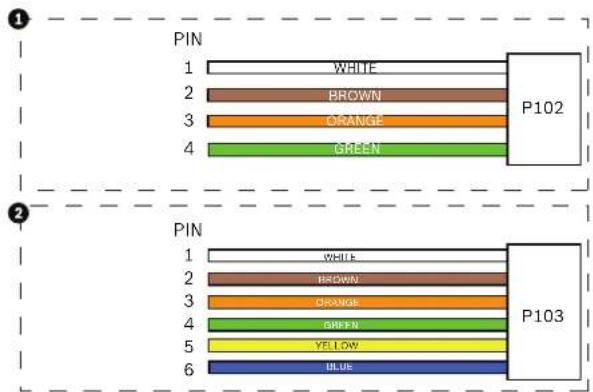
text_image
PIN 1 WHITE 2 BROWN 3 ORANGE 4 GREEN P102 PIN 1 WHITE 2 BROWN 3 ORANGE 4 GREEN 5 YELLOW 6 BLUE P103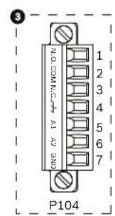
text_image
NO COMMERCIAL A1 A2 BND 1 2 3 4 5 6 7 P104Figure 2.3 Alarm and relay connectors
| 1 4-pin Alarm Connector(P102) | 2 6-pin Alarm In Connector(P103) | 3 7-pin Relay Connector(P104) | |||
| Pin | Description Pin Description | Pin Description | |||
| 1 Alarm Out 1 1 Alarm In 3 1 | No | mally Open | |||
| 2 Alarm Out 2 2 Alarm In 4 2 | COM | ||||
| 3 Alarm Out 3* | 3 | Alarm In 5 3 Normally Closed | |||
| 4 Alarm Ground | 4 | Alarm In 6 4 Earth Ground | |||
| 5 Alarm In 7 5 Analog Alarm 1 | |||||
| 6 Alarm Ground | 6 | Analog Alarm 2 | |||
| 7 | Ground | ||||
- If you are connecting supervised alarms and relays, attach the supplied 7-pin Relay Connector to the appropriate incoming wires. Refer to Figure 2.3, Page 18, above, for the wire connections. Refer to Section 6 Alarms and Relay Connections, page 69 for more details about wiring alarms and relays.
2.4.2 Power Supply Box Connections
The following figure is a detailed illustration of the Pendant Arm Power Supply Box, which includes the fuse specifications.

text_image
TRANSFORMER (115/250VAC MODELS) P101 XF-101 1 2 3 7 4 5 4a P106 8 5 4 3 2 1 P105 5 4 3 2 1 P107 J102 XF-103 (LED) XF-102 (FUSE) (PUSE) ① ② ③ ④ ⑤ ⑥ ⑦ ⑧ ⑨ ⑩ ⑪Figure 2.4 Pendant arm power supply box
| 1 Ground Screw 6 In/Out; 1/2 in. (15 mm) NPS Fitting | ||
| 2 From Harness 7 P101 Connector; Power In | ||
| 3 In/Out; 1/2 in. (15 mm) NPS Fitting 8 P106 | Connector; Control In/Out | |
| 4 Video 9 P105 Connector; Control to Dome | ||
| 4a UTP/ Ethernet(Ethernet for VG5 700 Series only) | 10 Power In; 3/4 in. (20 mm) NPS Fitting | |
| 5 | 24 VAC to Dome | 11 Control Data and Video In/Out; 3/4 in. (20 mm)NPS Fitting |

WARNING!
Fuse replacement by qualified service personnel only. Replace with same type fuse.
| Fuse Specifications | |||
| Volts | XF101 Mains | XF102 Camera | XF103 Heater |
| 24 V | T 5.0 A | T 2.0 A | T 3.15 A |
| 115 V | T 1.6 A | T 2.0 A | T 3.15 A |
| 230 V | T 0.8A | T 2.0 A | T 3.15 A |
The following table lists the Power Supply Box connectors:
| No. | Connector | Pin 1 | Pin 2 | Pin 3 | Pin 4 | Pin 5 | Pin 6 |
| Ground | Grounding Screw | ||||||
| P101 115/230 VAC or 24 VAC Power In | Line | NC | Neutral | ||||
| P105 Control to Dome (Arm Harness) | C-(Biphase) | C+(Biphase) | Earth Ground | RXD (+)(RS-232/485) | TXD (-)(RS-232/485) | Signal Ground | |
| P106 Control In/Out C- | (Biphase) | C+(Biphase) | Earth Ground | RXD (+)(RS-232/485) | TXD (-)(RS-232/485) | Signal Ground | |
| P107 24 VAC Power (Arm Harness) | Dome 24 VAC | Dome 24 VAC | Earth Ground | Heater(24 VAC) | Heater(24 VAC) | ||
Table 2.1 Power Supply Box Connections
2.5 Route Power through Intermediate Power Supply Box
You may route the main power supply through a VG4-PSU1 (120 V transformer) or through a VG4-PSU2 (230 V transformer) Power Supply Box before connecting the power to a VG4-PA0 (24 V, no transformer) Power Supply Box. The main issue with this configuration is that the 5-pin power out connector from the VG4-PSU1 or VG4-PSU2 does not match to the 3-pin power input of the VG4-PA0 power supply. The illustration below depicts:
- A VG4-PSU1/VG4-PSU2 Power Supply Box.
- The main power supply connected to the P101 connector and to the grounding screw.
- The 24 VAC power out wire connected to the P107 heater power connectors.
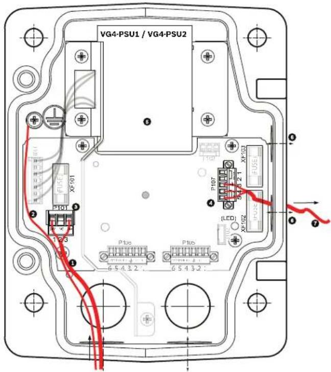
text_image
VG4-PSU1 / VG4-PSU2 P107 FX-01 P108 FX-03 (LED) FX-02 FX-03 P105 FX-01 P106 FX-02 P107 FX-03 P108 FX-03 P109 FX-03 P110 FX-03 P111 FX-03 P112 FX-03 P113 FX-03 P114 FX-03 P115 FX-03 P116 FX-03 P117 FX-03 P118 FX-03 P119 FX-03 P120 FX-03 P121 FX-03 P122 FX-03 P123 FX-03 P124 FX-03 P125 FX-03 P126 FX-03 P127 FX-03 P128 FX-03 P129 FX-03 P130 FX-03 P131 FX-03 P132 FX-03 P133 FX-03 P134 FX-03 P135 FX-03 P136 FX-03 P137 FX-03 P138 FX-03 P139 FX-03 P140 FX-03 P141 FX-03 P142 FX-03 P143 FX-03 P144 FX-03 P145 FX-03 P146 FX-03 P147 FX-03 P148 FX-03 P149 FX-03 P150 FX-03Figure 2.5 VG4-PSU1/VG4-PSU2 Power Supply Box
| 1 | 120/230 VAC Power In | 5 | Transformer |
| 2 | Ground Wire | 6 | In/Out Conduit (1/2 in. [15 mm] NPS Fitting |
| 3 | P101 Connector | 7 | 24 VAC Power Out to VG4-PA0 |
| 4 | P107 Connector |
To properly wire the incoming high voltage and the outgoing low voltage lines, refer to this table:
| No. | Connector | Pin 1 | Pin 2 | Pin 3 | Pin 4 | Pin 5 | Pin 6 |
| Ground | Grounding Screw | ||||||
| P101 | 115/230 VAC Power In | Line | NC | Neutral | |||
| P107 | 24 VAC Power Out | Earth Ground | Heater (24 VAC) | Heater (24 VAC) | |||
Table 2.2 VG4-PSU1/VG4-PSU2 Power Supply Box Connections
- Route the high voltage 115/230 VAC lines through the conduit fitting on the left side of the box. The Power Supply Box with a transformer comes with a barrier that separates the high voltage side on the left, from the low voltage 24 VAC side on the right.
- Cut and trim the high voltage 115/230 VAC power and ground wires with sufficient slack to reach their connector terminal in the box, but not so long as to be pinched by or to obstruct closing the cover door.
- Attach the supplied 3-pin power plug to the incoming high voltage power wires in the box. Refer to connector P101 in Table 2.2, Page 21 and to the image below for an illustration of these connections:

Figure 2.6 Incoming 115/230 VAC power supply
- Attach the ground wire to the grounding screw.
- Connect three wires to the P107 Power Out connector to route the 24 VAC power supply to the VG4-PA0 Power Supply Box.
a. Connect the first wire to pin 5 (HN: Heater Neutral) connector.
b. Connect the second wire to pin 4 (HL: Heater Line) connector.
c. Connect the third wire to pin 3 (Earth Ground) connector.
Refer to connector P107 in Table 2.2 and to the image below for an illustration of these connections:
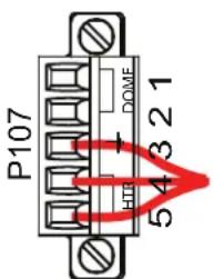
text_image
P107 DOME 54321Figure 2.7 Outgoing 24 VAC power supply

WARNING!
Ensure that you connect the outgoing power supply wires to the P107 heater connectors (HN and HL). The heater power (XF103) fuse can handle a higher amperage (3.15 A) than the camera power (XF102) fuse (2.0 A).
-
Route the 24 VAC outgoing power supply wires into the VG4-PA0 power supply box through the conduit fitting on the left side of the box.
-
Cut and trim the 24 VAC power and ground wires with sufficient slack to reach their connector terminal in the box, but not so long as to be pinched by or to obstruct closing the cover door.
-
Attach the supplied 3-pin power plug to the incoming 24 VAC power wires in the box, as illustrated below.
text_image
(101) (FUSE) XF101 P101 1/2 3 (2) P106 6 5 4 3 2 1 P105 6 5 4 3 2 1 (LED) XF102 FUSE P107 5 4 3 2 1 XF103 JL102Figure 2.8 VG4-PA0 Power Supply Box
| 1 | Incoming 24 VAC Power Supply Wires (from VG4-PSU1/VG4-PSU2 power supply box) |
| 2 | Ground Wire |
| 3 | P101 Connector |
| 4 | Control Data and Video In/Out Wires |
- Follow the instructions in Section 2.6 Attach Pendant Arm to Power Supply Box, page 23, to continue the installation.
2.6 Attach Pendant Arm to Power Supply Box
The bottom hinge pin of the Pendant Arm is provided with a Hinge Pin Stop to hold the hinge open while attaching the arm to the Power Supply Box.
- Compress the bottom hinge pin by pushing the pin lever downward and rotating it behind the Hinge Pin Stop.

natural_image
Technical line drawing of an electrical connector assembly showing internal components and wiring (no text or symbols)Figure 2.9 Pendant Arm to Power Box Hinge Alignment
- Open the top hinge by pushing its pin lever up and holding it.

NOTICE!
Both Hinge Pins must be fully compressed to open (unlock) the hinges of the Pendant Arm and before proceeding to the next step.
-
While continuing to hold the top hinge pin open and align the top and bottom hinges of the Pendant Arm to their mating points on the Power Supply Box. See Figure 2.9, above, for an illustration.
-
Once you have the hinges aligned, release the top hinge pin to engage its mating hinge on the power box. Then release the bottom hinge pin from the Hinge Pin Stop to lock the Pendant Arm to the Power Supply Box.

WARNING!
Serious injury or death can occur if the hinge pins of the Pendant Arm are not fully engaged (locked) to the Power Supply Box. Exercise caution before releasing the Pendant Arm.
2.7 Make Connections in Power Supply Box
Refer to Table 2.2, Page 21 to locate the various connectors in the power supply box and make the following connections detailed below.
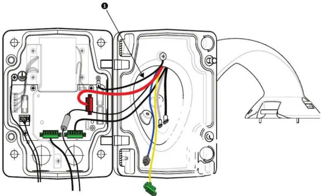
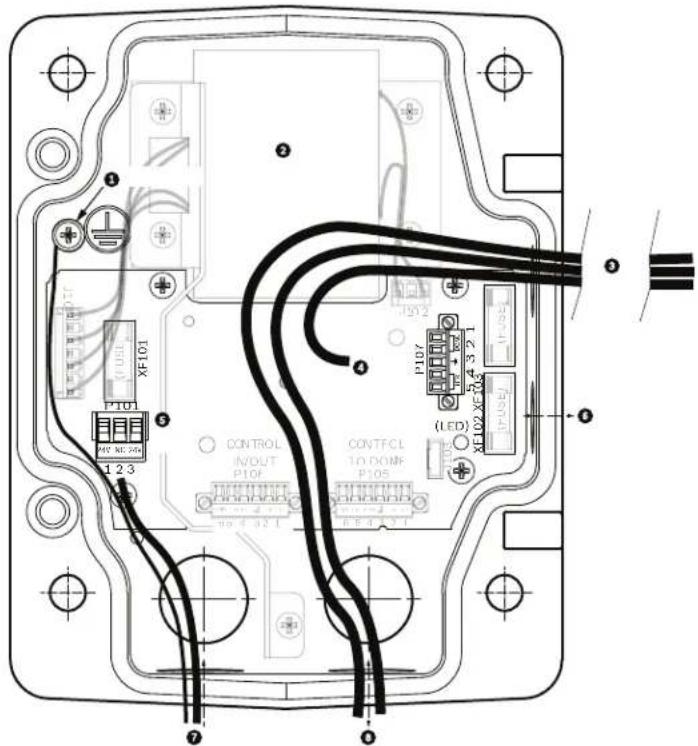
text_image
Technical diagram of an electronic device showing internal wiring connections and labeled componentsFigure 2.10 Pendant Arm connections to Power Supply Box
- Attach the earth ground wire (item 1 in the illustration above) to the grounding screw on the left side of the power box.
- Connect the 6-pin Control In/Out Plug, installed previously, to its mating connector P106 in the power box. If this product is a Fiber Optic model this step is not required, since all control data is sent through the fiber cable.
- Connect the 6-pin Control to Dome Plug from the Pendant Connector Harness to its matting connector P105 in the power box. (For Fiber Optic model connect to the P106 connector.)
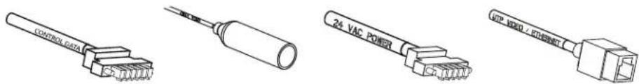
text_image
CONTROL DATA 24 VAC POWER HOP MWD / KONOMTControl Data Coax Video 24 VAC Power UTP Video/Ethernet

(Ethernet for VG5 700 Series only)
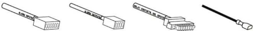
text_image
Alarm Elects Alarm Elects Relay Contact, I2S ElectsAlarm Inputs Alarm Outputs Relays
Grounding Strap

WARNING!
Do not connect the RJ45 connector unless using UTP video or Ethernet.
- Connect the 5-pin, 24 VAC to Dome Plug from the Pendant Connector Harness to its corresponding color mating connector P107 on the right side of the box.
- Connect the BNC plug to the BNC connector from the Pendant Connector Harness and slide its plastic cover over the connection.
- To connect alarm inputs and relay outputs, connect the 4-pin Alarms Out, the 6-pin Alarms In and the 7-pin Relay connectors from the Pendant Connector Harness to their mating connectors, installed previously, to the incoming alarm wires.
- Connect the 3-pin Power In Plug, installed previously, to its matting connector P101 on the left side of the box.
- If installing a Fiber Optic model attach the incoming ST fiber plug, installed previously, to its mating connector on the Fiber Optic Module in the power supply box. Then attach the video BNC plug to the BNC connector from the Pendant Connector Harness. Refer to Section 5 Cable and Wire Standards, page 61 for fiber optic specifications.
text_image
Technical diagram of an electronic device with labeled components and wiring, including GND and C++ connectorsFigure 2.11 Optional Fiber Optic Module
| 1 Transformer 5 In/Out | |||
| 2 BNC to Dome 6 ST Connector (Fiber) | |||
| 3 | I n / | O | u t 7 |
| 4 From | Arm Harness 8 Data In/Out | ||
P o w e r l
- If using UTP for video, connect the incoming RJ45 video connector, installed previously, to its mating connector from the Pendant Connector Harness. Refer to Section 5 Cable and Wire Standards, page 61 for connections and specifications.
- Attach the grounding strap of the Pendant Arm to the Power Supply Box. Refer to Figure 2.10, Page 24.
- After making the harness connections to the Power Supply Box, rotate the Pendant Arm to close and seal the Power Supply Box and tighten the two (2) captive screws to 10-12 N-m (90-105 in.-lbs).
- Refer to Section 2.9 Attach Pendant to Arm and Tighten, page 31, to continue the VG5 AutoDome Installation procedure.

NOTICE!
After all wiring is complete, close the cover door and tighten the two (2) captive screws on the cover door to 10-12 N-m (90-105 in.-lbs) to ensure the Power Supply Box is watertight.
2.8 Installing the VG4-A-ARMPLATE
This section provides instructions to install a wall, corner, or mast mount with the VG4-A-ARMPLATE Mounting Plate instead of a Power Supply Box.

CAUTION!
You must route the main power supply through a 120/230 VAC transformer (VG4-PSU1 or VG4-PSU2 power supply box) before connecting the power to a 24 VAC AutoDome.

WARNING!
A stud diameter of 6.4 mm (1/4 inch) to 8 mm (5/16 inch) able to withstand a 120 kg (265 lb) pull-out force is recommended. The mounting material must be able to withstand this pull out force. For example, 19-mm (3/4-inch) minimum for plywood.
1. For a Corner installation:
a. Secure the Corner Plate to the wall corner using four (4) studs (not included).
b. Secure the Mounting Plate to the Corner Plate using the four (4) 3/8 x 1-3/4-inch bolts and split lock washers (supplied).
2. For a Mast or pole installation:
The metal straps included with the Mast mount accommodate a pole with a diameter of 100–380 mm (4–15 in.). You must use a banding tool (sold separately) for a mast or pole installation. In addition, you must obtain a 3/4 in. (20-mm) right angle conduit connector through which you route the wires that connect to the pendent arm.
a. Follow the instructions provided with the banding tool to securely mount the Mast Plate to the pole. Contact your Bosch Sales Representative to order Banding Tool P/N TC9311PM3T.
b. Secure the Mounting Plate to the Mast Plate using the four (4) 3/8 x 1-3/4-inch bolts and split lock washers (supplied).
c. Remove one of the rubber gaskets from the Mounting Plate.
d. Once the Mounting Plate (item 1, below) is attached to the Mast Plate (item 2), connect the right angle conduit (item 3) to the Mounting Plate through the empty conduit hole as shown below:

natural_image
Technical line drawing of a mechanical housing component with three numbered parts (1, 2, 3), no visible text or symbols.- Ensure that the mounting plate is secure.
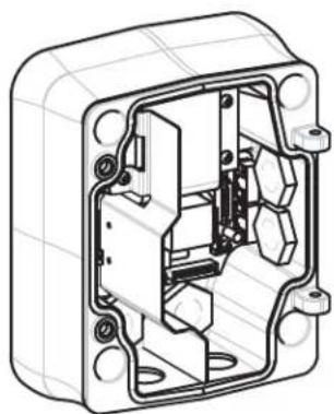
2.8.1 Attach the Pendant Arm to the Mounting Plate
The bottom hinge pin of the Pendant Arm is provided with a Hinge Pin Stop to hold the hinge open while attaching the arm to the Mounting Plate.
- Compress the bottom hinge pin by pushing the pin lever downward and rotating it behind the Hinge Pin Stop.

text_image
VGA-REPLATS MATH PROCESSED PLUG, PE MTB MTBFigure 2.12 Connect Pendant Arm to Mounting Plate
- Open the top hinge by pushing its pin lever up and holding it.
Note: Both Hinge Pins must be fully compressed to open (unlock) the hinges of the Pendant Arm and before proceeding to the next step.
-
While continuing to hold the top hinge pin open, align the top and bottom hinges of the Pendant Arm to their mating points on the Mounting Plate. Refer to Figure 2.12, above, for an illustration.
-
Once you have the hinges aligned, release the top hinge pin to engage its mating hinge on the Mounting Plate. Then release the bottom hinge pin from the Hinge Pin Stop to lock the Pendant Arm to the Mounting Plate.
2.8.2 Route and Connect Wires to a Power Supply Box
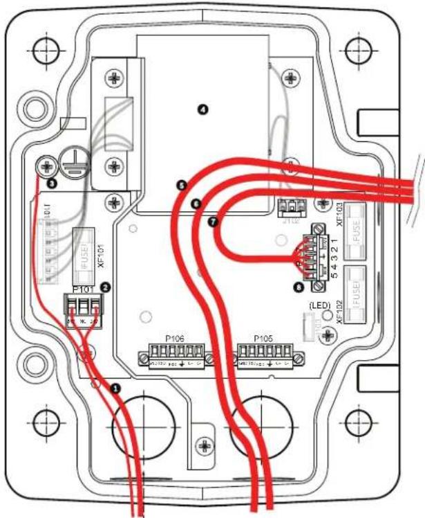
The illustration below depicts the power and control cables connected to the Pendant Arm:

text_image
Technical diagram of a mechanical assembly with numbered components for identificationFigure 2.13 Pendant Arm Cables
| Cable Cable | |||
| 1 Grounding Strap (black) 5 UTP Video/Ethernet (blue)(Ethernet for VG5 700 Series only) | |||
| 2 24 VAC Power (red) 6 Alarm Outputs (white) | |||
| 3 Relay Contacts (yellow) 7 Alarm Inputs (gray) | |||
| 4 Coax Video (black) 8 Serial Communications (green) | |||
- Route all incoming wires through one of the conduits at the bottom of the Mounting Plate. For a mast mount, route all wires through the right-angle conduit.
- Attach the water-tight plug to the other conduit.
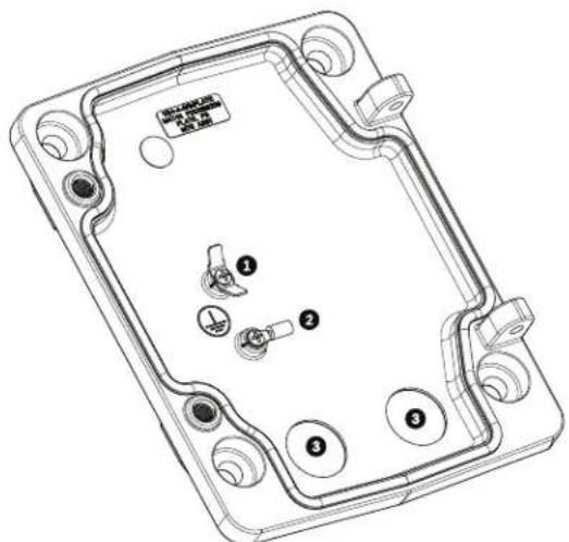
- Attach the grounding spade terminal (item 1, below) to one of the spade terminals inside the Mounting Plate.
text_image
Technical diagram of a device casing with numbered components and labeled partsFigure 2.14 Mounting Plate - Inside Detail
| Ref. Description |
| 1 Grounding lug with two spade terminals |
| 2 Earth ground lug with crimp ring terminal |
| 3 Wire input conduit holes |
- Connect the incoming 24 VAC power wires to the 5-pin, 24 VAC Power In mating connector (supplied with the Mounting Plate kit) for the Dome and for the Heater.

natural_image
Line drawing of a mechanical or electrical component with a U-shaped tube and connector (no text or symbols)- Attach the grounding spade from the 5-pin mating connector (item 1, Figure 2.14) to the other spade terminal inside the mounting plate.
- Attach the 5-pin Power In mating connector to the 24 VAC Power cable (cable 2) connected to the pendant.
- Remove the mating connector from the Relay Contacts cable (cable 3).
- Connect the incoming relay contact wires to the mating connector. Then, reattach the mating connector to the Relay Contacts cable.
- Attach a BNC connector to the incoming video coax cable. If using UTP for video attach an RJ45 plug to the incoming UTP cable. If installing a Fiber Optic model, attach an ST fiber plug to the optic fiber cable. Refer to Section 5 Cable and Wire Standards, page 61, for the different methods of transmitting video and control protocols, and wire specifications.
Note: Do not connect the RJ45 connector unless using UTP video.
-
Connect the incoming video coax cable to the BNC connector (cable 4) and slide its plastic cover over the connector.
-
If using UTP for video, connect the incoming RJ45 video connector, installed previously, to the UTP Video/Ethernet cable (cable 5). Refer to Section 5 Cable and Wire Standards, page 61, for detailed wire and connection information.
- Connect the outgoing alarm wires to the flying leads coming from the 4-pin Alarm Outputs cable (cable 6).
- Connect the incoming alarms wires to the flying leads coming from the 6-pin Alarm Inputs cable (cable 7).
- Connect the incoming serial communication wires to the 6-pin mating connector supplied with the VG4-A-ARMPLATE kit. Ensure that the 100 resistor remains connected to the Biphase C- and the Biphase C+ terminals. Remove the resistor only in the following cases: - If the AutoDome is not the last AutoDome in a daisy chain.
- If the Biphase C- and the Biphase C+ terminals receive a line input audio signal. Refer to Section 5 Cable and Wire Standards, page 61, for detailed wire and connection information.
- Attach the 6-pin serial communication mating connector to the Serial Communication (cable 8) cable.
- Connect the Earth ground wire, if available, to the crimp ring terminal inside the Mounting Plate. Refer to Figure 2.14 above.
Note: The Earth ground is not provided with the VG4-A-ARMPLATE kit; it is a ground connection made at the installed location. - After making the harness connections to the Mounting Plate, rotate the Pendant Arm to close and tighten the two (2) captive screws to 10-12 N-m (90-105 in.-Ibs).

NOTICE! After all wiring is complete, close the cover door and tighten the two (2) captive screws on the cover door to 10-12 N-m (90-105 in.-lbs).
2.9 Attach Pendant to Arm and Tighten

NOTICE!
Before attaching the AutoDome Pendant, visually inspect the dome and arm connectors for any blocked pin holes or bent pins.
- Tilt the bottom of the dome toward the pendant arm base and place the mounting hook, located on top of the dome housing, over the recessed hinge pin of the arm.

text_image
Technical diagram showing mechanical assembly with numbered components and directional arrows indicating motion or movement.Figure 2.15 Attach Pendant to Arm
| 1 | T i l t u p . |
| 2 Hook and drop. | |
| 2a Recessed Hinge Pin | |
| 2b Dome Connector | |
| 3 Rotate down to engage dome connector. | |
| 4 Tighten the two (2) mounting screws to a minimum torque of 10-12 N-m(90-105 in.-lbs). | |

- Drop the dome housing down slightly to engage the dome housing hook on the Pendant Arm hinge pin, allowing the dome to rotate around the pin.
- Rotate the dome housing down to a vertical position and gently push upward to engage the connector on top of the dome housing.
CAUTION!
If you feel any resistance when rotating the dome housing or when engaging the connector, stop immediately and start over.
- Hold the Pendant housing in position while tightening the two (2) 5-mm Allen head mounting screws on top of the housing to 10-12 N-m (90-105 in.-lbs).

CAUTION!
You must tighten the two mounting screws to a minimum torque of 10-12 N-m (90-105 in.-lbs) to ensure a proper seal between the arm and the housing.
3 Installing Roof Parapet and Pipe Mounts
3.1 Unpacking
This equipment should be unpacked and handled with care. If an item appears to have been damaged in shipment, notify the shipper immediately.
Verify that all the parts listed in the product's Parts List below are included. If any items are missing, notify your Bosch Security Systems Sales or Customer Service Representative. Refer to Section 1.4 Customer Support and Service, page 12, for contact information.
The original packing carton is the safest container in which to transport the unit and must be used if returning the unit for service. Save it for possible future use.
3.1.1 Parts List
The following table lists the optional parts you may need for attaching a Pendant to the Roof Parapet and Pipe mount packages:
| Mounting Options Part Numbers | |
| Parapet (Roof) Mount with one of the following Power Supply Boxes: VG4-A-9230 | |
| – Power Supply Box with 120 VAC transformeror 230 VAC transformer | VG4-A-PSU1VG4-A-PSU2 |
| – Power Supply Box with Fiber Optic Module and 120 VAC transformer,or 230 VAC transformer | VG4-A-PSU1FVG4-A-PSU2F |
| – Power Supply Box without transformer (24 VAC) and with Fiber Optic Module | VG4-A-PSU0F |
| Optional Flat Roof Mount Adapter for VG4-A-9230 Mount (not included) LTC 9230/01 | |
| Pipe Mount with one of the following Power Supply Boxes: VG4-A-9543 | |
| – Power Supply Box with transformer 120 VACor 230 VAC transformer | VG4-A-PSU1VG4-A-PSU2 |
| – Power Supply Box with Fiber Optic Module and 120 VAC transformeror 230 VAC transformer | VG4-A-PSU1FVG4-A-PSU2F |
| – Power Supply Box without transformer (24 VAC) and with Fiber Optic Module | VG4-A-PSU0F |
3.1.2 Description
Chapter 3 details how to install a VG5 AutoDome to a Roof Parapet or to a Pipe mount. Any differences to the installation between these two mounting systems are noted. Refer to Section 2 Installing the Pendant Arm Wall, Corner, and Mast (Pole) Mounts if you are installing a Pendant Arm to a Wall, Corner, or Mast (or pole) or refer to Section 4 Installing the In-Ceiling Mount if you are mounting an In-ceiling AutoDome.
The VG4-A-9230 Series are stationary mounts intended for rooftop parapet vertical walls. They are made of light weight aluminum with a corrosion-resistant finish and are used for all Bosch AutoDome Cameras up to a rated load of 29 kg (64 lb). These mounts can be fitted to the inside or outside of parapet walls and can swivel for ease of positioning and for servicing the AutoDome.
3.1.3 Tools Required
- 5 mm Allen wrench (supplied)
- Small straight blade screwdrivers \~ 2.5 mm (0.1 in.) - 3.1 mm (1/8 in.)
- Medium straight blade screwdriver
- No. 1 and No. 2 Phillips screwdrivers
- Socket wrench and 9/16 in. socket
- Pipe Wrench
- Barrel connector (if installing a fiber optic model)
3.2 Pre-installation Check List
- Determine the location and distance for the power supply box based on its voltage and current consumption. Refer to Section 5 Cable and Wire Standards, page 61 for wiring information and distances.
- Use only UL listed liquid tight strain reliefs for conduits to the Power Supply Box to ensure that water cannot enter the box. You must use water tight conduits and fittings to meet NEMA 4 standards.

NOTICE!
Power and I/O cabling must be routed separately inside different permanently earthed metal conduits.
-
Install all rough wiring including: power, control, video coax, alarms I/O, relay I/O, and fiber optic cabling. Refer to Section 5 Cable and Wire Standards, page 61 for video and control protocol methods.
-
If you plan to use the RS232 or RS485 protocol to control the AutoDome, refer to Section 5.4.2 Controlling the AutoDome via the RS232 Protocol, page 64, or Section 5.4.3 Controlling the AutoDome via the RS485 Protocol, page 65, for instructions on configuring the AutoDome to accept these protocols.

WARNING!
External interconnecting cables are to be installed in accordance to NEC, ANSI/NFPA70 (for US application) and Canadian Electrical Code, Part I, CSA C22.1 (for CAN application) and in accordance to local country codes for all other countries.
Branch circuit protection incorporating a 20 A, 2-pole Listed Circuit Breaker or Branch Rated Fuses are required as part of the building installation. A readily accessible 2-pole disconnect device with a contact separation of at least 3 mm must be incorporated.
-
Choose the appropriate VG5 AutoDome model (indoor or outdoor) for the environment in which it will be used.
-
Choose the appropriate mounting kit to use depending on the location of the AutoDome: Parapet (Roof) mount or the Pipe mount.

CAUTION!
Select a rigid mounting location to prevent excessive vibration to the AutoDome camera.
3.3 Mount Power Supply Box
Before mounting the Power Supply Box decide if you will be wiring the box through the holes in the bottom or back of the box. If wiring the box through the back, move the two (2) seal plugs to the bottom holes before mounting.

NOTICE!
Use 3/4-inch NPS (20-mm) fittings for the holes on the bottom and back of the box. Use 1/2-inch NPS (15-mm) fittings for the side holes. Refer to Section 3.1.1 Parts List, page 33, for an illustration.
natural_image
Technical line drawing of an open electrical enclosure with internal components (no text or symbols)Figure 3.1 Wall Mount Power Supply with Optional Trim Skirt
- Use the wall mount template supplied in the packaging box to locate the four (4) mounting holes for the Power Supply Box.
- Drill four (4) holes for the mounting anchors. If installing outdoors, apply a weatherproof sealant around each hole at the mounting surface.
- Place the Power Supply Box into the optional Trim Skirt.
- Secure the Power Supply Box to the wall using four (4) corrosion-resistant stainless steel studs (not included).

NOTICE!
A stud diameter of 6.4 mm (1/4 in.) or 8 mm (5/16 in.), able to withstand a 120 kg (265 lb) pull-out force is recommended.
- Attach the 3/4 in. (20 mm) watertight pipe fittings (not supplied) to the holes of the Power Supply Box through which you will run the power, video, and control data wires.
3.3.1 Attach Cover Door
- Compress the bottom hinge pin by pushing the pin lever down and then rotate it behind the Hinge Pin Stop. The power box Cover Door provides a Hinge Pin Stop to hold the bottom hinge open while attaching the door.

text_image
① 90° ② ③ ④ ⑤ ⑥ ⑦Figure 3.2 Align Cover Door Hinge to Power Box
| 1 Power Supply Box 5 Hold Hinge Pin Open |
| 2 Cover Door 6 Open Position |
| 3 Align Top Hinge 7 Hinge Pin Stop |
| 4 Align Bottom Hinge |
- Open the top hinge by pushing its pin lever outward and holding it open.
Note: Both Hinge Pins must be fully compressed to open (unlock) the female hinges of the Cover Door before proceeding to the next step.
- While holding the top hinge pin open, position the Cover Door to the Power Supply Box and align its hinges.
- When the hinges are aligned, release the top hinge pin to engage its mating hinge on the power box. Then release the bottom hinge pin from the Hinge Pin Stop to complete attaching the Cover Door to the Power Supply Box.

NOTICE! After all wiring is complete, close the cover door and tighten the two (2) captive screws on the cover door to 10-12 N-m (90-105 in.-lbs) to ensure the Power Supply Box is watertight.
3.4 Route Wires and Attach Connectors
Power wires must be routed to the left (front) side of the Power Supply Box through a separate conduit. All video, control, and alarm wires must be routed through a second conduit to the right side of the box. Refer to Section 5 Cable and Wire Standards, page 61 for methods of transmitting video and data, and for wire specifications.

WARNING!
External interconnecting cables are to be installed in accordance to NEC, ANSI/NFPA70 (for US application) and Canadian Electrical Code, Part I, CSA C22.1 (for CAN application) and in accordance to local country codes for all other countries.
Branch circuit protection incorporating a 20 A, 2-pole Listed Circuit Breaker or Branch Rated Fuses are required as part of the building installation. A readily accessible 2-pole disconnect device with a contact separation of at least 3 mm must be incorporated.
3.4.1 Methods for Routing Wires
There are two possible methods to route the video, control, and alarm wires:
- One is to route the video, control, and alarm wires through the conduit fitting on the right (front) side of the Power Supply Box and out to the AutoDome Interface Board.
text_image
Technical diagram of an electrical enclosure with labeled components and red wiring connectionsFigure 3.3 VG4-A-PSU1 or VG4-A-PSU2 Power Supply Box
| 1 120 VAC/230 VAC Power In 5 Coax, UTP Video, or Ethernet Wire(Ethernet for VG5 700 Series only) | |
| 2 P101 Connector 6 Control Wire | |
| 3 Ground Connection 7 24 VAC Power Out | |
| 4 Transformer 8 P107 Connector | |
- The second method is to bypass the Power Supply Box and route the video, control, and alarm wires directly to the Interface Board. You connect only the power wires inside the Power Supply Box.
text_image
Technical diagram of an electronic device with labeled ports, connectors, and wiring connectionsFigure 3.4 VG4-A-PSU1 or VG4-A-PSU2 Power Supply Box Connected to Pipe Interface Board
| VG4-A-PSU1/VG4-A-PSU2 Pipe Interface Board | |||
| 1 | 1 | 20 VAC/230 VAC Power In 7 P | 101 C connector |
| 2 | P | 101 Connector 8 P107 Connector | |
| 3 | Ground Connection 9 24 VAC Power In (to AutoDome) | ||
| 4 | Transformer | 10 Earth Ground | |
| 5 | 24 VAC Power Out | 11 24 VAC Power In (to AutoDome) | |
| 6 | P | 107 Connector 12 24 VAC Power In (to Heater) | |
| 13 24 VAC Power In (to Heater) | |||
| 14 AutoDome Power | |||
| 15 Heater Power | |||

NOTICE!
Fiber Optic Models require that the Biphase control wires be routed from the Power Supply Box P106 connector out to the Pipe Interface Board P105 connector.
3.4.2 Wiring the Power Supply Box
- Route the high voltage 115/230 VAC lines through the conduit fitting on the left side of the box.

NOTICE!
The Power Supply Box with transformer comes with a barrier that separates the high voltage side on the left from the low voltage 24 VAC side on the right.
- Cut and trim the high voltage 115/230 VAC power and ground wires with sufficient slack to reach their connector terminal in the box, but not so long as to be pinched by or to obstruct closing the Cover Door. Refer to Section 3.1.1 Parts List, page 33, for connector location.
- Attach the supplied 3-pin Power Plug to the incoming high voltage power wires in the box. Refer to connector P101 in Table 3.1, Page 42.
- If you are using UTP for video, route the UTP cable out to where the AutoDome will be mounted. Refer to Section 5 Cable and Wire Standards, page 61 for fiber optic specifications.
- Route the low power 24 VAC wires from the right side of the Power Supply Box out to where the AutoDome will be mounted. Attach the supplied 5-pin 24 VAC Dome plug to the wire ends inside the box. Refer to connector P107 in Table 3.1, Page 42.

NOTICE!
All video, control, and alarm wires either pass through the Power Supply Box or by-pass it and connect directly to the Pipe Interface Board.
3.4.3 Wiring the Fiber Optic Model
- If installing a Fiber Optic model, bring the fiber optic cable into the right side of the power supply box.
- If installing a Fiber Optic model attach the incoming ST fiber plug, installed previously, to its mating connector on the Fiber Optic Module in the power supply box. Refer to Section 5 Cable and Wire Standards, page 61 for fiber optic specifications.

NOTICE!
You will need a barrel connector (not supplied) to connect the BNC connector from the Pipe Interface Board coax cable to the Fiber Optic Module BNC connector.
- Route the control wires from the Power Supply to the Pipe Interface Board. Then attach the supplied six (6) pin control data connector to the wires in the Power Supply Box.

text_image
(GND) ① ② ③ ④ ⑤ ⑥ ⑦| 1 | T r a n s | f | o r m e r |
| 2 BNC to Dome 6 ST Connector (Fiber) | |||
| 3 | l n / O u | t | 7 P o w e |
| 4 From Arm Harness 8 Data In/Out | |||
5 l n / O u t
r l n
3.4.4 Power Supply Box Connections
The following figure is a detailed illustration of the Roof or Pipe Mount Power Supply Box, which includes the fuse specifications.
text_image
Technical diagram of an electrical control panel with labeled components and wiring connections| 1 Ground Screw 5 Power In | ||
| 2 Transformer (115/230 VAC Modes) 6 In/Out; 1/2 in. (15 mm) NPS Fitting | ||
| 3 In/Out to Dome 7 Power In; 3/4 in. (20 mm) NPS Fitting | ||
| 4 24 VAC to Dome Interface Board 8 Control Data and Video In/Out; 3/4 in. (20 mm)NPS Fitting | ||

WARNING!
Fuse replacement by qualified service personnel only. Replace with same type fuse.
| Fuse Specifications | |||
| Volts XF101 Mains XF102 Camera XF103 Heater | |||
| 24 V | T 5.0 A | T 2.0 A | T 3.15 A |
| 115 V | T 1.6 A | T 2.0 A | T 3.15 A |
| 230 V | T 0.8A | T 2.0 A | T 3.15 A |
The following table lists the Power Supply Box connectors:
| No. | Connector | Pin 1 | Pin 2 | Pin 3 | Pin 4 | Pin 5 | Pin 6 |
| Ground | Grounding Screw | ||||||
| P101 1 | 15/230 VAC or 24 VAC Power In | Line | NC | Neutral | |||
| P105 C | Control to Dome (Fiber Optic Model) | C-(Biphase) | C+(Biphase) | Earth Ground | RXD (+)(RS-232/485) | TXD (-)(RS-232/485) | Signal Ground |
| P106 C | Control In/Out (Optional) | C-(Biphase) | C+(Biphase) | Earth Ground | RXD (+)(RS-232/485) | TXD (-)(RS-232/485) | Signal Ground |
| P107 2 | 4 VAC Power to Dome Plug | Dome 24 VAC | Dome 24 VAC | Earth Ground | Heater(24 VAC) | Heater(24 VAC) | |
Table 3.1 Power Box Connections
3.5 Installing the VG4-A-9230 Roof Parapet Mount
This section details the installation steps for the Roof Parapet Mount. If you are installing a pipe mount, refer to Section 3.6 Installing the VG4-A-9543 Pipe Mount, page 45, for instructions.
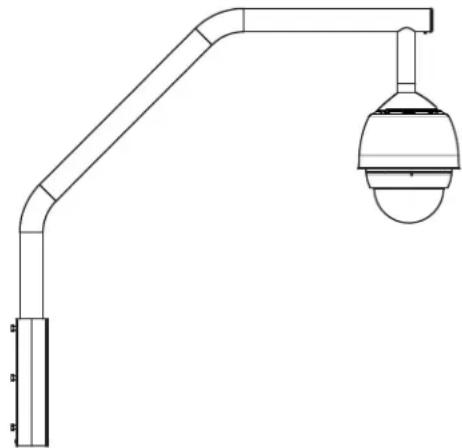
natural_image
Technical line drawing of a mechanical support structure with a spherical sensor or camera component (no text or symbols)Figure 3.5 VGA-A-9230 Parapet Roof Mount
- Determine the wall location on the roof for the AutoDome and use the Parapet wall mount bracket as a template to mark the hole locations.

NOTICE! Allow enough room below the Parapet Mount Bracket to route the video, control and alarm wires up through the Parapet arm. In certain installations you may have to lift the Parapet arm for the AutoDome to clear the top of the wall when it is swung into position. Provide enough slack in the wires to rotate the pipe arm over the roof and back when camera maintenance is required.
- Prepare the mounting surface for the type of fastener by drilling holes for the mounting anchors as required.

text_image
Technical diagram showing a mechanical assembly with numbered components and directional arrows indicating motion or force.
Figure 3.6 Parapet Wall Mount Bracket and Roof Mount Plate
| 1 Pipearm 4 Apply sealant around each fastener hole | |
| 2 Parapet Wall Bracket 5 Roof Mount Plate | |
| 3 3/8-16 SS Hex Head Bolt (supplied) 6 Use a minimum of six (6) fasteners (not supplied). Eight (8) fastener holes shown. | |

NOTICE! Fasteners are not supplied with the Roof Parapet Mount Kit since it depends on the material to which it is attached. The material must accommodate a minimum pull out strength of 275 kg (600 lbs). For example, 19 mm (3/4 inch) minimum for plywood. Fasteners can include bolts, studs, or lag bolts. All fasteners must be made of corrosion-resistant stainless steel, with a diameter of 10 mm (3/8 inch).
All bolts must fully extend through the mounting surface and be secured with a flat washer, lock washer and a nut. All studs must be anchored to concrete or welded to a steel backing plate. Anchor bolts can be used for blind structures where there is no access to the rear.
-
Apply a weatherproof sealant around each fastener hole at the mounting surface.
-
Attach the Parapet Wall Bracket using at least six (6) stainless steel fasteners, three (3) on each side (the bracket has eight (8) holes). Be careful not to over tighten the fasteners because it may strip the threads. If attaching the parapet mount to a flat roof, attach the optional LTC 9230/01 Roof Mount Plate to the roof and then attach the Parapet Wall Bracket to the Roof Mount Plate.
-
Insert the Parapet Pipe Arm into the mounting bracket until it bottoms in the bracket.
-
Remove the End Cap from the front of the arm and feed the video, control, and power wires up through the bottom of the pipe arm and out the front end.

text_image
Technical diagram of a mechanical assembly with numbered components for identificationFigure 3.7 VG4-A-9230 Parapet Mount
| 1 | End Cap with O-ring |
| 2 | Parapet Pipe Arm |
| 3 | 1/4-20 SS Cap Screw |
| 4 | D o w n P i p e |
| 5 | 10-24 SS Pan Head Screw |
- Fold the video, control, and power wires back at the front end of the arm and route them down and out through the Down Pipe. Then replace the End Cap.
- Wrap at least five layers of Teflon tape around the Down Pipe threads.
-
Apply the supplied thread sealant to the Down Pipe threads:
-
Make sure all surfaces are clean and dry.
-
Apply a bead of sealant completely around the leading threads of the male fitting.
– Force the adhesive into the threads to thoroughly fill all voids. -
Thread the Dome Cap onto the down pipe and tighten securely. See the illustration below.

WARNING!
You must thread the Dome Cap onto the Down Pipe until it is tight. Failure to do so can result in damage, serious injury, or death.
text_image
Technical diagram of a mechanical component with labeled parts and directional arrows indicating motion or force.Figure 3.8 Attach Dome Cap
| 1 Thread Sealant or tape | |
| 2 | D o m e C a p |

- Run a bead of RTV Silicon sealant around the down pipe/Dome Cap interface to seal any gaps between the down pipe and the Dome Cap.
- Proceed to Section 3.7 Wire the Pipe Interface Board, page 46.
NOTICE!
Use a guy-wire to aid in stabilizing the Parapet Arm. Replace the 1/4 inch cap screw with a threaded 1/4-inch stainless steel eye bolt (not supplied). Loop the guy-wire through the eye bolt and attach both ends to anchor spots on the roof. Refer to Figure 3.7, Page 44.
3.6 Installing the VG4-A-9543 Pipe Mount
This section details the installation steps for the VG4-A-9543 Pipe Mount. If you are installing the Roof Parapet mount, refer to Section 3.5 Installing the VG4-A-9230 Roof Parapet Mount, for instructions.

NOTICE! Customer must supply 1-1/2 inch (NPS) pipe threaded on both ends with a minimum length of 5 inches (12.7 cm).
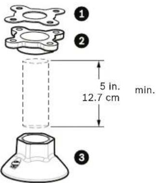
text_image
① ② 5 in. 12.7 cm min. ③Figure 3.9 Pipe Mount
| 1 | G a s k e t |
| 2 Flange | |
| 3 | Cap |
- Before installing the Top-Mounting Flange, ensure there is an adequate opening in the ceiling or mounting structure for the wires to pass through.
- Secure the pipe Flange with supplied gasket to the ceiling or other supporting structure using four (4) 10-mm (3/8-inch) diameter fasteners.

NOTICE!
Each fastener must have a minimum pullout strength of 275 kg (600 lbs). The mounting material must be able to withstand this pull-out force. For example, 19-mm (3/4-inch) minimum for plywood.
- Attach pipe (not supplied) to the Top-mounting Flange.

WARNING!
You must thread the pipe onto the Top-mounting Flange until it is tight. Failure to do so can result in damage, serious injury or death.
- Route the power, video, control, and alarm wires through the Top-Mounting Flange and down the pipe.
-
Wrap at least five layers of Teflon tape around the threads.
-
Apply the supplied thread sealant to the threads on the Pipe.
-
Make sure all surfaces are clean and dry.
- Apply a bead of sealant completely around the leading threads of the male fitting.
-
Force the adhesive into the threads to thoroughly fill all voids.
-
Thread the Pipe Cap onto the down pipe and tighten securely to prevent leaks. Refer to Figure 3.9, Page 45.

WARNING!
You must thread the Dome Cap onto the pipe until it is tight. Failure to do so can result in damage or serious injury or death.
3.7 Wire the Pipe Interface Board
This section provides instructions for connecting wires and cables to the Pipe Interface Board, as illustrated below. Refer to Section 5 Cable and Wire Standards, page 61 for cable and wiring recommendations and specifications.

text_image
BNC J102 P105 6 5 4 3 2 1 7 6 5 4 3 2 1 8 3 2 1 9 3 2 1 10 P107 P101 P103 AGND OUT 3 OUT 2 OUT 1 AGND A7 A6 A5 A4 A3 P102 P104 P103 11 10TJ P106Figure 3.10 Pipe Interface Board Connections
| Ref. | Description Connector Wire Gauge | Pin Description | |||
| 1 Pipe | Interface Module | ||||
| 2 Video | Coax In J102 | ||||
| 3 6-pin | Connector Alarms In (3-7) P103 | ||||
| 4 4-pin | Connector Alarms Out (1-3) P102 | ||||
| 5 100 | Ω Resistor P105 | ||||
| 6 | Data In/Out | P105 | AWG 26-16 | 1 | Biphase (C-) |
| 2 | Biphase (C+) | ||||
| 3 | Earth Ground | ||||
| 4 | RxD + | ||||
| 5 | TxD - | ||||
| 6 | Signal Ground | ||||
| 7 | Alarms In (EOLR Supervised, 1-2) | P104 | AWG 26-16 | 7 | Ground |
| 6 | Alarm 2 | ||||
| 5 | Alarm 1 | ||||
| 4 | Earth Ground | ||||
| 8 | Relay Output | P104 | AWG 26-16 | 3 | Normally Closed |
| 2 | Common | ||||
| 1 | Normally Open | ||||
| 9 | Dome Power | P101 | AWG 18-14 | 3 | Dome 24 VAC |
| 2 | Earth Ground | ||||
| 1 | Dome 24 VAC | ||||
| 10 | Heater Power | P107 | AWG 18-14 | 2 | Heater 24 VAC |
| 1 | Heater 24 VAC | ||||
| 11 | RJ45 Ethernet or UTP Video(Ethernet for VG5 700 Series only) | J101 | |||
| 12 | To AutoDome | ||||
3.7.1 Wiring for Multiple AutoDomes
To wire multiple AutoDomes in a series, or “daisy chaining,” you must apply a terminating resistor to the last dome of the series. The Interface Board is supplied with a 100 Ω terminating resistor located between the Biphasse terminals C- and C+ (pins 1 and 2) of the P105 control connector (see item 5 in Figure 3.10 above). Remove the resistor from all but the last AutoDome Interface Board. The maximum number of AutoDomes that can be daisy chained is four (4).
If using the RS485 protocol for control, switch the terminating resistor from the Biphas C+ and C- terminals to the RxD+ and TxD- terminals (pins 4 and 5) of the P105 control connector for the last dome (refer to item 6 in Figure 3.10 above).
3.7.2 Connecting Wires to the Pipe Interface Board
The Pipe Interface Board contains all of the connectors for control, data, image, and power wires. Follow the procedures below to make the proper connections.

WARNING!
Use a 24 VAC Class 2 power supply only.
- Attach a BNC connector to the video coax cable and connect it to its mating connector J102 on the Pipe Interface Board.
- If using UTP for video, attach an RJ45 connector plug to the UTP cable and connect the plug to its mating connector J101 on the Pipe Interface Board.

WARNING!
Do not connect the RJ45 connector unless using UTP video. This connection causes video distortion.
- Attach the control data in/out wires to their respective terminals on the P105 connector on the Pipe Interface Board. Refer to Figure 3.10, Page 46, for an illustration of these connections.
- Connect the 24 VAC power wires to the P101 connector on the Pipe Interface Board. If this model has a heater, connect the 24 VAC heater power wires to connector P107.

CAUTION!
To protect the AutoDome from damage due to cold temperatures, ensure that you connect the 24 VAC heater power wires to the P101 connector.
- To connect alarm inputs and outputs, attach the supplied 6-pin Alarms In and the 4-pin Alarms Out connector plugs with flying leads to the appropriate alarm wires. Then connect the plugs to their mating connectors P103 and P102 on the Pipe Interface Board.
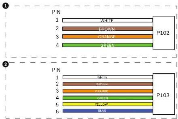
text_image
1 PIN 1 WHITE 2 BROWN 3 ORANGE 4 GREEN P102 2 PIN 1 WHITE 2 BROWN 3 ORANGE 4 GREEN 5 YELLOW 6 BLUE P103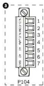
text_image
3 VOCOMING A2 BND 1 2 3 4 5 6 7 P104Figure 3.11 Alarm and Relay Connector Plugs
| 1 4-pin Alarm Connector(P102) | 2 6-pin Alarm In Connector(P103) | 3 7-pin Relay Connector(P104) |
| Pin Description Pin Description | Pin Description | |
| 1 Alarm Out 1 1 Alarm In 3 1 Alarm | rm Out 4 Normally Open | |
| 2 Alarm Out 2 2 Alarm In 4 2 Alarm | rm Out 4 COM | |
| 3 Alarm Out 3* 3 | Alarm In 5 3 Alarm Out 4 Normally Closed | |
| 4 Alarm Ground 4 | Alarm In 6 4 Earth Ground | |
| 5 Alarm In 7 5 Analog Alarm 1 | ||
| 6 Alarm Ground 6 | Analog Alarm 2 | |
| 7 Ground |
- To connect supervised alarms and relays, attach the appropriate wires to their terminals on the P104 connector on the Pipe Interface Board (see Figure 3.11, above). In addition, refer to Section 6 Alarms and Relay Connections, page 69 for more details on wiring alarms and relays.
Note: There is a slot located at the top of the Interface Board to tie the wires to the circuit board with a cable tie.
- Insert the Pipe Interface Board into the down pipe and fasten the three (3) retaining screws to secure the board to the Dome Cap.

CAUTION!
Be careful not to strip the threads when tightening the Pipe Interface Board retaining screws.

text_image
Technical diagram of a mechanical device with numbered components and directional arrows indicating movement or force.Figure 3.12 Pipe Interface Board to Dome Cap Assembly
| 1 Interface Board |
| 2 Retaining Screws (3) |
| 3 Pendant Mounting Screws (2) |
3.8 Attach Pendant to Pipe and Tighten
-
Before attaching the Pendant, visually inspect the Pendant dome and the Interface Board connectors for any blocked pin holes and bent pins.
-
Tilt the Pendant enough to place its mounting hook on top of the its housing, over the recessed hinge pin of the Dome Cap.
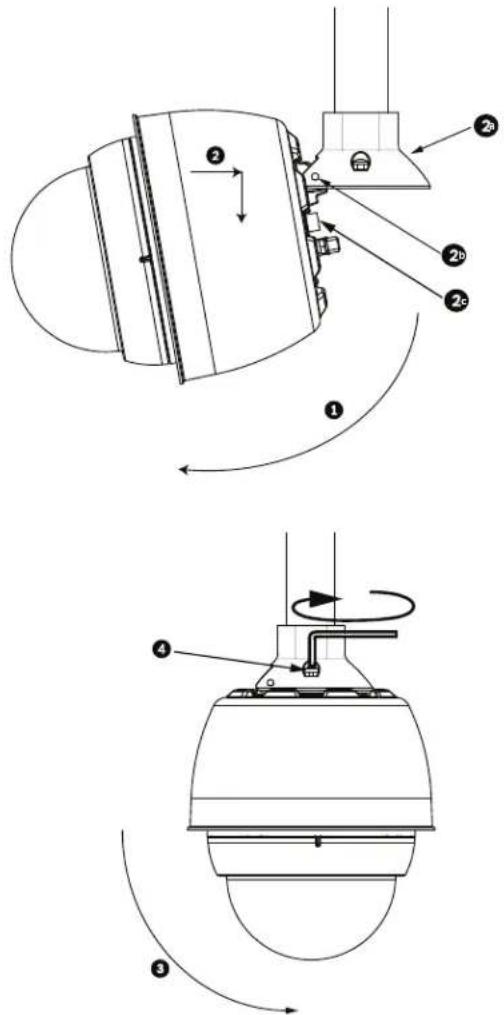
text_image
Technical diagram showing mechanical assembly with numbered components and rotational motion arrowsFigure 3.13 Pendant to Roof / Pipe Mount Attachment
| 1 | T i l t D o m e |
| 2 Hook and drop | |
| 2a Dome Cap | |
| 2b Recessed Hinge Pin | |
| 2c Dome Connector | |
| 3 Rotate down to engage dome connector | |
| 4 Tighten the two (2) mounting screws to a minimum torque of 10-12 N-m(90-105 in.-lbs) | |

- Drop the Pendant down slightly to engage the dome hook and hinge pin of the Dome Cap, allowing the dome to rotate around the hinge pin.
- Rotate the dome housing down to a vertical position and gently push upward to engage the connector on top of the dome housing.
CAUTION!
If you feel any resistance when rotating the dome housing or when engaging the connector, stop immediately and start over.

- Hold the housing firmly in position and alternately tighten the two (2) 5-mm Allen head mounting screws from above to a torque value of 10-12 N-m (90-105 in.-Ibs).
CAUTION!
You must tighten the two mounting screws to a minimum torque of 10-12 N-m (90-105 in.-Ibs) to ensure a proper seal between the arm and the housing.
- Rotate the arm to swing the AutoDome out from the roof and into position, if installing a Parapet Roof Mount.
- Tighten the three (3) 10-mm (3/8-inch) stainless steel hex bolts on the bracket to lock the Parapet Arm in position. Refer to Figure 3.13, Page 50, for an illustration.

CAUTION!
Do not over tighten the bolts. The maximum torque is 34 N-m (25 ft-lb).
3.9 Make Connections in the Power Supply Box
The following procedure references Figure 3.6, Page 43 to locate the various connectors in the box and to make the proper connections.
- Attach the earth ground wire to the grounding screw on the left side of the box.
- Connect the 24 VAC to Dome plug, installed previously, to its mating connector P107 on the right side of the box.
- Connect the 115/230 VAC, 3-pin Power-in plug, installed previously, to its matting connector P101 on the left side of the box.
3.9.1 Connections for Fiber Optic Models
The following procedure references Figure 3.6, Page 43.
- If installing a Fiber Optic model, attach the incoming ST fiber plug to its mating connector on the Fiber Optic Module in the power box.
- Connect the video BNC connector from the dome to the Fiber Optic Module BNC connector.

NOTICE! A BNC barrel connector (not supplied) is required to connect the male BNC of the dome to the male BNC connector of the Fiber Optic Module.
- Connect the six (6) control plugs from the dome, installed previously, to the P106 control I/O connector in the Power Supply Box.
4 Installing the In-Ceiling Mount
4.1 Unpacking
This equipment should be unpacked and handled with care. If an item appears to have been damaged in shipment, notify the shipper immediately.
Verify that all the parts listed in the product's Parts List below are included. If any items are missing, notify your Bosch Security Systems Sales or Customer Service Representative. Refer to Section 1.4 Customer Support and Service, page 12, for contact information.
The original packing carton is the safest container in which to transport the unit and must be used if returning the unit for service. Save it for possible future use.

NOTICE!
If your application of the VG5 Series AutoDome in-ceiling mount is required to meet the IP54 environmental rating you must obtain the optional VGA-IP54K-IC Gasket Kit and follow the directions included with the kit.
4.1.1 Parts List
The following table lists the parts included with the In-ceiling mount packages.
| In-ceiling Mount | ||
| Quantity Item | Part Number | |
| 1 | Interface Box | VG4-S-BIM |
| 1 | Bracket Assembly | LTC 9349MK |
4.1.2 Description
This chapter details how to install the AutoDome in an In-Ceiling Mount. The In-Ceiling AutoDome camera is suitable for use in environmental air spaces. Refer to Section 2 Installing the Pendant Arm Wall, Corner, and Mast (Pole) Mounts, or refer to Section 3 Installing Roof Parapet and Pipe Mounts for these specific installations.
4.1.3 Tools Required
- Straight slot screwdrivers \~ 2.5 mm (0.1 inch) - 3.1 mm (1/8 inch)
- No. 2 Phillips screwdriver
- Appropriate tool for cutting a hole in drywall or ceiling tile
- Pliers
4.2 Pre-installation Check List
- Determine the location and distance for the power supply box based on its voltage and current consumption. Refer to Section 5 Cable and Wire Standards, page 61 for specifications.
- Install all rough wiring including: power, control, video, alarms I/O, relay I/O, and fiber optic cabling.
- If you plan to use the RS232 or RS485 protocol to control the AutoDome, refer to Section 5.4.2 Controlling the AutoDome via the RS232 Protocol, page 64, or Section 5.4.3 Controlling the AutoDome via the RS485 Protocol, page 65, for instructions on configuring the AutoDome to accept these protocols.

WARNING!
24 VAC Class 2 power supply only.
- A minimum of 216-mm (8 1/2-inch) of air space above the ceiling is required to install the In-ceiling Mount.
4.3 Dimensions
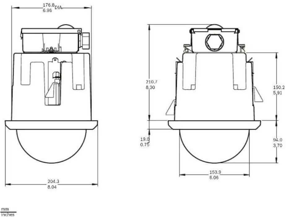
mm
inches
Figure 4.1 In-ceiling Dimensional Outline
4.4 Prepare Drywall Ceiling for Installation
- Choose the desired location to mount the dome.
- Use the bracket Base Plate as a template cut a 7 in. hole with a tolerance of ±1/8 in. (177.8 mm ±2.2 mm) hole in the ceiling with a drywall utility saw or Jig Saw. Proceed to Section 4.6 Wire the Interface Box, page 55, for further instructions.
4.5 Prepare Suspension Ceiling for Installation
- Choose the desired location to mount the dome, and remove an adjacent ceiling tile.
- Loosen the four (4) securing screws, located in the corners of the Bracket Assembly, enough to hold the suspension bars but still allowing adjustment during installation.
- Place the Bracket Assembly over the ceiling tile, which is used to mount the In-Ceiling AutoDome. Then snap the Bar Clips of the bracket to the ceiling rails.
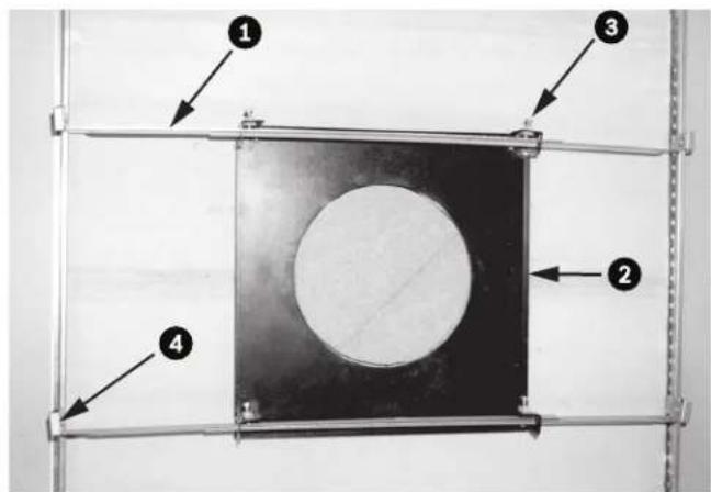
text_image
Diagram of a mechanical or structural component with numbered parts labeled 1 to 4, showing a central circular feature and surrounding frame.Figure 4.2 Suspension Ceiling Bracket (Top View)
| 1 Suspension Bars 3 Securing Screw (4) | |||
| 2 Base Plate 4 Bar Clips | |||
- Use the bracket Base Plate as a template or cut a 7 in. hole with a tolerance of ±1/8 in. (177.8 mm ±2.2 mm) hole in the center of the ceiling tile with a drywall utility saw or Jig Saw.

natural_image
Close-up of a mechanical testing setup with a tool applying material to a circular sample on a metal frame (no visible text or symbols)Figure 4.3 Cut Hole in Ceiling Tile
- Tighten the four (4) securing screws to the Bracket Assembly.

natural_image
Close-up of a hand holding a small transparent object over a dark surface, with metal rods extending from it (no visible text or symbols)Figure 4.4 Tighten Bracket Securing Screw
- Secure the Bracket Assembly to an overhead securing point with a safety wire.
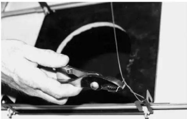
natural_image
Close-up of a hand holding a pliers next to a curved wire on a dark surface, with no visible text or symbols.Figure 4.5 Secure Bracket Assembly
4.6 Wire the Interface Box
The Interface Box can be wired through the top or side. Use the supplied rubber plug to seal the hole which will not be used to route wires.
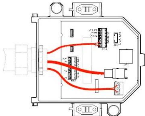
text_image
Technical diagram of an electrical connector with labeled ports and wiring pathsFigure 4.6 Interface Box Connections
4.6.1 Make the Connections
After routing all video, control, power, and alarm wires:
- Attach a 3/4-inch NPS (20-mm) conduit fitting to the hole in which you bring in the wires. Be sure to thread the inside nut to the conduit fitting.
- Route the video, control, power, and alarm wires through the conduit fitting and into the Interface Box.
- Cut and trim the wires allowing for sufficient slack to their respective terminals in the box.

NOTICE!
If installing the dome to a drywall ceiling, allow enough wire to make the connections in the Interface Box below the ceiling. Refer to Figure 4.6, Page 55, for connector locations and Table 4.1, Page 58, for wire connections.
- Attach the remaining control data in/out wires to their respective terminals in the Interface Box. Refer to Table 4.1, Page 58, for terminal connections.
- If using UTP for video, you must attach an RJ45 connector plug to the incoming UTP cable and connect it to its matting connector J101 in the Interface Box. Refer to Section 5 Cable and Wire Standards, page 61 for specifications.
Note: Do not connect the RJ45 connector unless using UTP video.
-
Connect the 24 VAC power wires to the P101 connector in the Interface Box.
-
To connect alarm inputs and outputs, attach the supplied 6-pin Alarms In and the 4-pin Alarms Out connector plugs with flying leads to the appropriate alarm wires. Then connect the plugs to their mating connectors P103 and P102 in the Interface Box.

text_image
① PIN 1 WHITE 2 BROWN 3 ORANGE 4 GREEN P102 ② PIN 1 WHITE 2 BROWN 3 ORANGE 4 GREEN 5 YELLOW 6 BLUE P103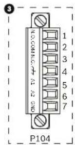
text_image
3 P104Figure 4.7 Alarm and Relay Connector Plugs
| 1 4-pin Alarm Connector(P102) | 2* | 6-pin Alarm In Connector(P103) | 3 7-pin Relay Connector(P104) |
| Pin Description Pin Description | Pin Description | ||
| 1 Alarm Out 1 1 Alarm In 3 | 1 Normally Open | ||
| 2 Alarm Out 2 2 Alarm In 4 | 2 COM | ||
| 3 Alarm Out 3 3 Alarm In 5 | 3 Normally Closed | ||
| 4 Alarm Ground 4 | Alarm In 6 4 Earth | Ground | |
| 5 Alarm In 7 5 | Analog Alarm 1 | ||
| 6 Alarm Ground 6 | Analog Alarm 2 | ||
| * Low Voltage TTL (3.3V) can also be used. | 7 Ground | ||
-
To connect supervised alarms and relays, attach the appropriate wires to their terminals on the P104 connector on the Pipe Interface Board. Refer to Section 6 Alarms and Relay Connections, page 69 for more details on wiring alarms.
-
Attach the lid to the Interface box:
a. Align the slots on the lid with the two posts at the rear of the Interface box.
b. Rotate the lid down.
c. Squeeze the ground clips, located at the front of the box, against the Interface box with your fingers before closing the lid to ensure that the lid does not catch on the ground clips.
d. Secure the lid to the Interface box by pushing the lid down until the clip on the lid catches against the box.
4.6.2 Interface Box Connections
The following figure is a detailed illustration of the In-ceiling Interface box.
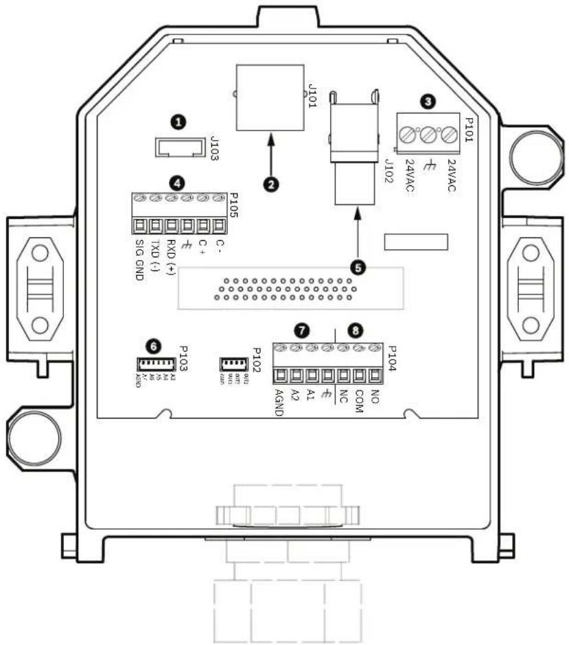
text_image
J101 J103 J102 P101 24VAC 24VAC P105 TXD (-) SIG GND C+ C- 5 7 8 P104 A2 A1 NC COM P102 M M1 M2 M3 M4 M5 M6 M7 M8 M9 M10 M11 M12 M13 M14 M15 M16 M17 M18 M19 M20 M21 M22 M23 M24 M25 M26 M27 M28 M29 M30 M31 M32 M33 M34 M35 M36 M37 M38 M39 M40Figure 4.8 In-ceiling Interface Box
| 1 Fiber Optics 5 Coax Video | ||
| 2 UTP/Ethernet Video(Ethernet for VG5 700 Series only) | 6 | A I a r m |
| 3 Dome Power 7 Analog In | ||
| 4 Data In/Out 8 Relay |
1 n
The following table summarizes the pin connectors and their function:
| No. | Connector | Pin 1 | Pin 2 | Pin 3 | Pin 4 | Pin 5 | Pin 6 | Pin 7 |
| P103 | Alarms In | Alarm 3 | Alarm 4 | Alarm 5 | Alarm 6 | Alarm 7 | AGND | |
| P102 | Alarms Out | Alarm 1 | Alarm 2 | Alarm 3 | GND | |||
| P104 | Analog Relay | RelayN.O. | RelayCOM | RelayN.C. | Earth | Alarm 1 | Alarm 2 | Ground |
| P105 | Data In/Out | C-(BiPhase) | C+(BiPhase) | EarthGround | RXD (+)(RS-232/485) | TXD (-)(RS-232/485) | SignalGround | |
| P101 | 24 VAC | Line | Earth | Neutral | ||||
| J102 Video BNC Connector Input | ||||||||
| J101 UTP/Ethernt(Ethernet for VG5700 Series only) | Connector Input | |||||||
Table 4.1 Interface Box Wire Terminals

WARNING!
24 VAC Class 2 power supply only.
4.7 Attach Housing to the Interface Box
The In-Ceiling Housing is attached to the Interface Box and secured by two (2) thumbscrews.
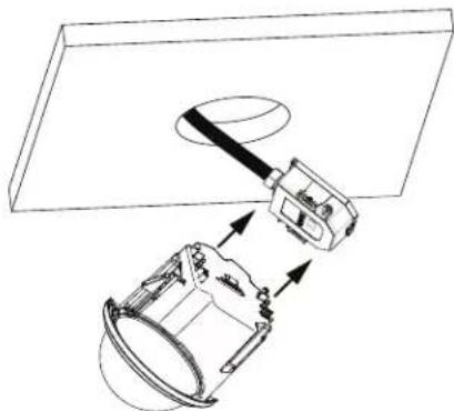
natural_image
Technical line drawing of a mechanical assembly with no visible text or symbolsFigure 4.9 Attach Housing to Interface Box
- Insert the In-ceiling housing through the hole in the ceiling to verify that the edge of the hole support the unit. Then remove the housing from the hole.
-
Align the ball studs of the In-Ceiling Housing to the Stud Retainers on Interface Box and attach.
-
Tighten the two (2) Thumbscrews to secure the Interface Box to the housing.
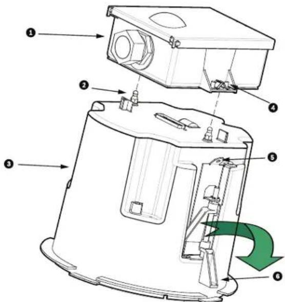
text_image
Technical diagram of a device with numbered components and directional arrows indicating motion or flow.Figure 4.10 In-Ceiling Housing and Interface Box
| 1 Interface Box 4 Thumb Screw | |
| 2 Ball Stud 5 Tether Point | |
| 3 In-ceiling Housing 6 Ceiling Clamp | |

CAUTION!
The In-ceiling dome is provided with tether points on each side of the housing. To prevent injury, attach a safety wire from a secure anchor point above the ceiling to a tether point on the dome housing, refer to Figure 4.11, Page 60, below for an illustration of this process.
4.8 Secure Housing to Ceiling
The In-ceiling Housing is secured to the ceiling by two (2) screw clamps.
- Insert the In-ceiling Mount Assembly through the hole in the ceiling.
- Tighten both clamps using a #2 Phillips screwdriver, to secure the housing to the ceiling.

text_image
12.7 MIN. 0.50 CEILING 41.7 MAX. 1.64 CEILING mm inchesFigure 4.11 Secure Dome to Ceiling
| 1 Tether Point 4 Ceiling Clamp | ||||
| 2 Ceiling Clamp 5 Rotate Cl | Clockwise to Engage Clamp | |||
| 3 | T | e | t | h |

CAUTION!
Over torquing the Ceiling Clamps can damage the clamp or ceiling. Only tighten the clamp until it contacts the ceiling and you start to feel some resistance. If using a power screwdriver, set the torque level to the lowest setting.
5 Cable and Wire Standards

CAUTION!
Installation should only be performed by qualified service personnel in accordance with the National Electrical Code or applicable local codes.

CAUTION!
All wires for installation applications must be routed through a grounded conduit.
5.1 Power
| 115/230 VAC | |
| Copper Wire To comply with local codes. | |
5.2 Wire Distance Guide for Pendant
| 24 V to AutoDome | ||||
| VA / Watts | 14 AWG (2.5 mm) 16 | AWG (1.5 mm) 18 | AWG (1.0 mm) | |
| AutoDome 100, Indoor | 14 / 7.5 | 248 m (813 ft) | 156 m (512 ft) | 98 m (322 ft) |
| AutoDome 100, Outdoor^1 | 47 / 43.5 | 74 m (242 ft) | 46 m (152 ft) | 29 m (96 ft) |
| 1. Standard heater module. Add Add 16 W if using VG4-SHTR-XT kit. | ||||
Table 5.1 Maximum Wire Distances from Power Supply to AutoDome Pendant
5.3 Video and Control Cables
5.3.1 Using Coaxial Cable to Transmit Video and Control
Coaxial cable terminated with BNC connectors is the most common method for transmitting composite video. Bilinx control data can also be sent over the same cable.
Bilinx is a Bosch 2-way communication protocol that allows remote control, configuration, and updates over a video coax cable. Bilinx is available on all VG5 100 and 600 Series AutoDomes. VG5 Series AutoDomes feature cable compensation or “Pre-Comp,” which extends the range of video from the head end.
| Cable Compensation | Maximum Distances | ||
| Video Only | Bilinx Control | ||
| Cable Type | Pre-comp OFF | Pre-comp ON | Pre-comp ON or OFF |
| RG-59/U | 300 m (1000 ft) | 600 m (2000 ft) | 300 m (1000 ft) |
| RG-6/U | 450 m (1500 ft) | 900 m (3000 ft) | 450 m (1500 ft) |
| RG-11/U | 600 m (2000 ft) | 1200 m (4000 ft) | 600 m (2000 ft) |
| Size | O.D. between 4.6 mm (0.181 in.) and 7.9 mm (0.312 in.) | ||
| Shield Copper braid: 95% | |||
| Central Conductor | Standard copper center | ||
| Terminal Connector | BNC | ||

WARNING!
Cable compensation (Pre-Comp) does not extend the range of Bilinx control. Pre-Comp is not available with VG5 700 Series AutoDomes.
5.3.2 Using UTP to Transmit Video and Control
Unshielded twisted pair (UTP) cable terminated with RJ45 male connectors are used to transmit composite video using pins 1(+) and 2(-). Typically, a Coax to UTP cable converter is required at the head-end of the system.
Bilinx control data can also be sent over the same two video wires (1 & 2). Bilinx is a Bosch 2-way communication protocol that allows remote control, configuration and updates over a passive UTP cable.
VG5 Series AutoDomes feature cable compensation or "Pre-Comp," which extends the normal range of control from the head end.

WARNING!
Do not connect the RJ45 connector unless using UTP video.
| Cable Compensation | ||
| Maximum Distance | ||
| Cable Type Pre-comp OFF Pre-comp ON | ||
| CAT5 UTP 229 m (750 ft) 450 m (1500 ft) | ||
| Terminal Connector RJ45 | ||
| Requirement Coax to UTP Converter | ||
The following figure illustrates the connections necessary to transmit video and control over a UTP cable.
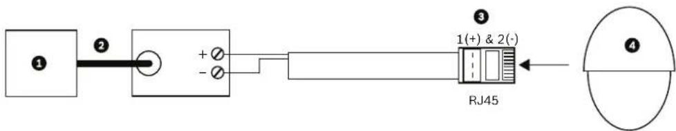
text_image
① ② + - ③ 1(+) & 2(-) RJ45 ④Figure 5.1 Video and Control over UTP
| 1 | Head End Video | 3 | Pins |
| 2 | Coax | 4 | AutoDome |
5.3.3 Using Multi-mode Fiber Optic to Transmit Video and Control
Fiber Optic kits, available for AutoDome 100 and 600 Series cameras, transmit both video and Biphase control over an analog singlemode or multimode fiber.
| Multimode | |
| Fiber Type | 50/125 μm, 62.5/125 μm, low loss multimode glass fiber |
| Maximum Distance | 4 km (2.5 miles) |
| Minimum Bandwidth | 20 MHz (Video - 850 nm / Control - 1300 nm) |
| Requirement | Bosch LTC 4629 Fiber Receiver at controller end of system |
| Terminal Connector | ST |
| Singlemode | |
| Fiber Type | 9/125 μm, low loss single glass fiber |
| Maximum Distance | 69 km (43 miles) |
| Minimum Bandwidth | 20 MHz (Video - 1310 nm /Control - 1550 nm) |
| Requirement | Single mode fiber receiver at controller end of system |
| Terminal Connector | ST |
5.4 Control-only Cables
5.4.1 Controlling the AutoDome via Biphase
(Shielded 2-wire, half-duplex, multi-drop, 5000 ft. cable limit)
Biphase is the standard Bosch protocol used to send Pan/Tilt/Zoom control over 2-wire shielded twisted pair (STP) terminated with a 100 Ω terminal resistor.
The AutoDome has a 100 Ω termination resistor between the Biphas C+ and C- terminals.

CAUTION!
The Biphase shield must be connected to the head end only.
| Cable Type STP - Shielded Twisted Pair | |
| Distance 1524 m (5000 ft) Belden 8760 recommended | |
| Transmission Rate 31.25 KHz | |
| Gage 1.02 mm (18 AWG) | |
| Termination 100 Ω | |
| Terminal Connector | Screw terminals |
| Voltage | 4 Vp-p |
The figure below illustrates the connections necessary for Biphase operation.
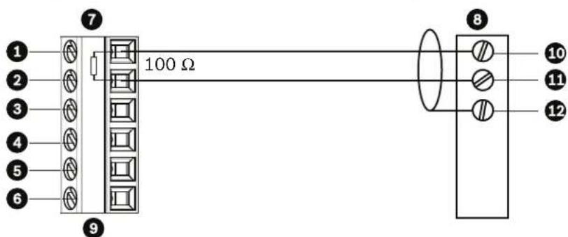
text_image
1 2 3 4 5 6 7 100 Ω 8 10 11 12Figure 5.2 Connections for Biphasse Operation
| 1 | C- (Biphase) | 7 | AutoDome Data In/Out |
| 2 | C+ (Biphase) | 8 | Head End Biphase |
| 3 | Earth Ground | 9 | P105/P106 Connector |
| 4 | RxD | 10 | C- (Biphase) |
| 5 | TxD | 11 | C+ (Biphase) |
| 6 | Signal Ground | 12 | Shield |
In a daisy chain configuration, where multiple domes are connected in series, the 100 Ω resistor must be removed from all but the last dome. You can daisy chain a maximum of four (4) AutoDomes.
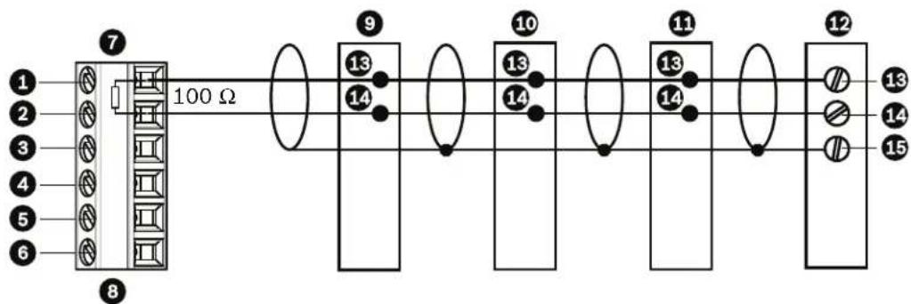
text_image
1 2 3 4 5 6 7 100 Ω 8 9 13 14 10 13 14 11 13 14 12 13 14 15Figure 5.3 Connections for a Daisy Chain Configuration
| 1 C- (Biphase) 9 Dome 3 | ||
| 2 C+ (Biphase) 10 Dome 2 | ||
| 3 Earth Ground 11 Dome 1 | ||
| 4 RxD | 12 Head End Biphase | |
| 5 TxD | 13 C- (Biphase) | |
| 6 Signal Ground | 14 C + (Biphase) | |
| 7 Last Dome Data In/Out | 15 Shield | |
| 8 P105/P106 Connector | ||
5.4.2 Controlling the AutoDome via the RS232 Protocol
(3-wire, full-duplex, single-ended, 50 ft. cable limit)
RS232 is a common, single-ended communication protocol used for control. Data transmission via 3-wires (TDX, RXD, common) is from one transmitter to one receiver at relatively slow baud rates (up to 57.6 Kbaud) and short distances up to 50 ft.

NOTICE!
After making the wire connections for RS232 operation, reposition the slide switch located on the CPU Module to the camera head inward and away from the LEDs.
| Wire Type | 3-wire (TXD, RXD, common) |
| Distance | 15 m (50 ft) |
| Maximum Baud Rate 5 | 7.6 Kb |
| Voltage ± 15 V | |
| Termination | 100 Ω |
| Slide Switch | Away from LEDs (factory default) |
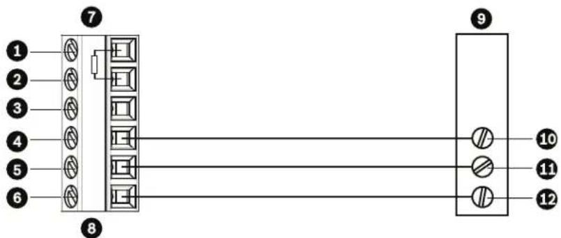
text_image
1 2 3 4 5 6 7 8 9 10 11 12Figure 5.4 Connections for RS232 Operation
| 1 C- (Biphase) 7 AutoDome Data In/Out | |||
| 2 C+ (Biphase) 8 P105/P106 Connector | |||
| 3 Earth Ground 9 Head End RS232 | |||
| 4 RxD 10 TxD | |||
| 5 TxD | 11 | RxD | |
| 6 Signal Ground 12 Ground | |||
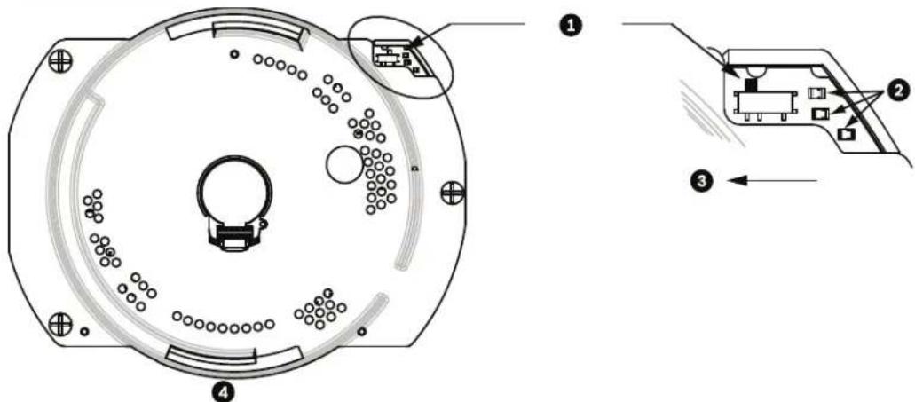
text_image
Technical diagram of a circular device with labeled components and internal wiring, showing exploded and assembled views.Figure 5.5 Position of CPU Switch for RS232 Operation (camera module not shown for clarity)
| 1 | Switch Location |
| 2 | LEDs |
| 3 | RS232 |
| 4 | CPU Module |
Note: To access the CPU switch you must remove the bubble from the pendant housing. Refer to the procedure on Page 73.
5.4.3 Controlling the AutoDome via the RS485 Protocol
2-wire (shielded), half-duplex, differential, multi-drop (32 nodes), 4000 ft cable limit) RS485 is capable of controlling a true multi-drop network and is specified for up to 32 drivers and 32 receivers on a single 2-wire bus. The AutoDome uses the 2-wire mode, although RS485 can be connected in a 2- or 4-wire mode.

NOTICE!
The wire shield must be tied to signal at both ends, if 2-wire twisted pair is used. After connecting the wires for RS485 operation, make sure the slide switch on the main board to the camera head is positioned toward the LEDs (default).

CAUTION!
Bosch recommends that multiple RS485 connections be arranged as a connected series of point-to-point (multi-dropped) nodes, as a line or as a bus. It is not recommended to arrange RS485 connections as a star, ring, or as a multiple-connected network. Star and ring topologies may cause signal reflections or excessively low or high termination impedance.
| Wire Type 2-wire shielded | twisted pair |
| Distance 1219 m (4000 ft) | |
| Maximum Baud Rate 57.6 | kb |
| Gage 0.511 mm (24 AWG) | |
| Wire Impedance 120 W | |
| Slide Switch Toward LEDs | (factory default) |
The following figure illustrates the connections for RS485 connections.
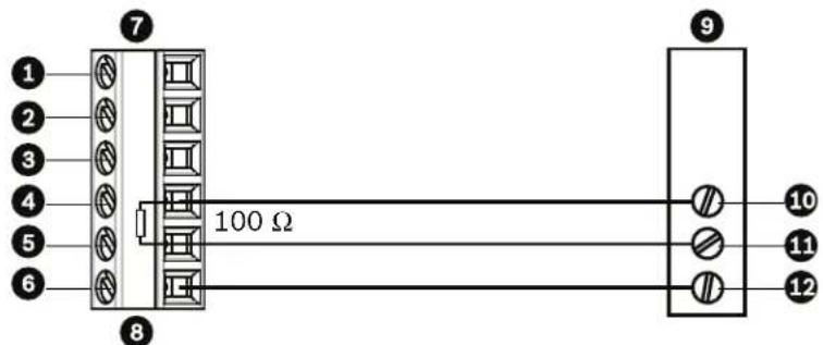
text_image
1 2 3 4 5 6 7 8 100 Ω 9 10 11 12Figure 5.6 Connections for RS485 Operations
| 1 C- | (Biphase) | 7 | AutoDome Data In/Out |
| 2 C+ | (Biphase) | 8 | P105/P106 Connector |
| 3 Earth Ground | 9 | Head End RS485 | |
| 4 RxD | 10 | Data + | |
| 5 TxD | 11 | Data - | |
| 6 Signal Ground | 12 | Ground | |
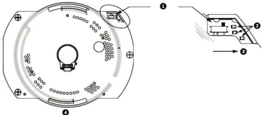
text_image
Technical diagram of a circular mechanical component with labeled parts and exploded view, showing internal structure and assembly steps.Figure 5.7 Position of CPU Switch for RS485 Operation (camera module not shown for clarity)
| 1 | Switch Location |
| 2 | LEDs |
| 3 | RS485 |
| 4 | CPU Module |
Note: To access the CPU switch you must remove the bubble from the pendant housing. Refer to the procedure on Page 73.
5.5 Fiber Optic Module with an RS232/RS422 Controller
An AutoDome with a fiber optic module is prewired to operate with Biphase signals only. This section describes the procedures necessary to control a VG5 series AutoDome fitted with a fiber optic kit using an RS232 controller or a Pelco® RS422 controller.
To control a VG5 Series Autodome from an RS232 or from a Pelco RS422 controller you must run control wires from the controller to an LTC 4629 head-end fiber optic module.
5.5.1 Connecting to an LTC 4629 Head End Data/Video Transceiver
-
Connect the RS232 cable (TxD from the controller) to the RS232 RxD port (pin 1) of the LTC 4629.
-
Connect the ground wire of the controller to Pin 2 on the LTC 4629.
5.5.2 Configuring the VG5 AutoDome
-
Disconnect the power to the VG4 power supply unit; then open the unit.
-
Remove the green Serial Communications wire from the P106 connector.
-
Remove the 100 Ω resistor across the C+ and C- pins.
-
Cut the five wires from the green Serial Communications wire mating connector. Ensure that the insulation covers each wire to avoid wires from touching.
-
Cut back the insulation on the blue (ground) wire and on the green (RxD) wire enough to be able to connect these wires back into the P106 connector.
-
Connect the blue (ground) wire to the C-pin on the P106 connector.
-
Connect the green (RxD) wire to the C+ pin on the P106 connector.
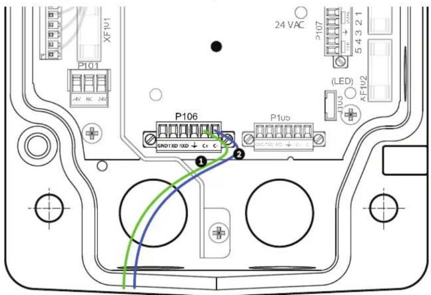
text_image
24 VAC P101 XFIU1 P106 GND1XD RXD + C+ C- P1us (LED) JU3 XFIU2 1 2 ① ②Figure 5.8 Detail of P106 Connections
| 1 Green RxD wire connected to C+ |
| 2 Blue Ground wire connected to C- |
-
Connect the fiber optic cable from the AutoDome to the LTC 4629.
-
Close the door to the power supply unit.
-
Ensure that the VG5 AutoDome is set to receive RS232 commands.
-
Remove the bubble from the VG5 AutoDome housing.
- Locate the protocol switch on the CPU board.
- Ensure that the protocol switch is in the left position for RS232 operation.

text_image
Technical diagram of a mechanical component with numbered parts and directional arrows indicating assembly or assembly steps.Figure 5.9 Position of CPU Switch for RS232 Operation
| 1 Switch Location | |||||||||
| 2 | L | E | D | s | |||||
| 3 Move Switch to the left for RS232 Operation | |||||||||
| 4 | C | P | U | M | o | d | u | l | e |
- Return the bubble to the AutoDome housing.
- Return power to the power supply box.
6 Alarms and Relay Connections
6.1 Alarm Inputs
The AutoDome provides seven alarm inputs. Each input can be activated by dry contact devices such as pressure pads, passive infrared detectors, door contacts, and similar devices. The table below summarizes the size and distance wires.
| Wire Size Maximum Distance | |||
| AWG | mm | feet | meters |
| 22 | 0.644 | 500 | 152.4 |
| 18 | 1.024 | 800 | 243.8 |
Table 6.1 Alarm wire guide
You wire alarms either Normally Open (N.O.) or Normally Closed (N.C.), and must program the alarm inputs N.O. (the default) or N.C. through the AutoDome main menu.
The AutoDome incorporates two (2) types of alarms: Non-supervised and Supervised. In addition to transmitting an alarm condition, a supervised alarm also transmits a tamper condition. Depending on how the alarm is configured, a short or a break in the alarm's circuit can trigger the tamper signal.
6.2 Configuring Supervised Alarms (inputs 1 and 2)
To configure Alarm 1 or 2 (pin 5 or 6) for supervision, you must install a 2.2 K end-of-line resistor in the circuit. Then, you program the alarms through the AutoDome main menu to either Normally Open Supervised (N.O.S.) or Normally Closed Supervised (N.C.S.).

NOTICE!
Only Alarms 1 and 2 (pins 5 or 6) can be configured for supervision. Once a supervised alarm is programmed it does not need to be enabled to indicate a tamper condition.
6.2.1 Configuring a Normally Open Supervised Alarm
- Install a 2.2 K end-of-line resistor in the alarm circuit.
- Connect the alarm wires to input 1 or 2 (pin 5 or 6) and to the ground (pin 7) at the AutoDome.

text_image
2.2K ① ② ③ ④Figure 6.1 N.O.S. - Normally Open Supervised Connections
| 1 | Dry Contact | 3 | Dome Connector |
| 2 | Alarm 1 or 2 only (Pin 5 or 6) | 4 | Ground (Pin 7) |
- From the AutoDome main menu, select Alarms Setup>Inputs Setup, and set the Alarm Input # to N.O.S. See the table below for contact and condition details.
| AutoDome Programmed N.O.S. | |
| Contact Alarm Condition | |
| Open Normal | |
| Closed Alarm | |
| Cut or brake Tamper | |
6.2.2 Configuring a Normally Closed Supervised Alarm
- Install a 2.2 K end-of-line resistor in the alarm circuit.
- Connect the alarm wires to input 1 or 2 (pin 5 or 6) and to the ground (pin 7) at the AutoDome.

text_image
2.2K ① ② ③ ④Figure 6.2 N.C.S. - Normally Closed Supervised Connections
| 1 | Dry Contact | 3 | Dome Connector |
| 2 | Alarm 1 or 2 only (Pin 5 or 6) | 4 | Ground (Pin 7) |
- From the AutoDome main menu select Alarm Setup>Inputs Setup, and set Alarm Input # to N.C.S. See the table below for contact and condition details.
| AutoDome Programmed N.C.S. | |
| Contact Alarm Condition | |
| Open Alarm | |
| Closed Normal | |
| Short | Tamper |
6.3 Configuring Non-supervised Alarms (inputs 1 through 7)
You can configure alarms 3 through 7 as non-supervised Normally Open (N.O.) or Normally Closed (N.C.) alarms.
6.3.1 Configuring a Normally Open Non-supervised Alarm
- Connect the alarm to the appropriate input (1 through 7) and ground at the AutoDome.
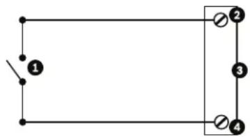
natural_image
Simple electrical circuit diagram with two parallel branches and a switch (no text or symbols)Figure 6.3 N.O. - Normally Open Non-supervised Connections
| 1 Dry Contact 3 Dome Connector | ||
| 2 Alarm Inputs 1 to 7 4 Ground | ||
- From the AutoDome main menu select Alarm Setup>Inputs Setup, and set Alarm Input # to N.O. See the table below for contact and condition details.
| AutoDome Programmed N.O. | |
| Circuit Alarm Indication | |
| Open Normal | |
| Closed | Alarm |
6.3.2 Configuring a Normally Closed Non-supervised Alarm
- Connect the alarm to the appropriate input (1 through 7) and ground at the AutoDome.
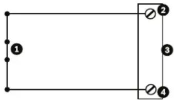
natural_image
Pure electrical circuit lines without any symbolsFigure 6.4 N.C. Normally Closed Non-supervised Connections
| 1 Dry Contact | 3 Dome Connector |
| 2 Alarm Inputs 1 to 7 | 4 Ground |
- From the AutoDome main menu select Alarm Setup>Inputs Setup, and set Alarm Input # to N.C. See the table below for contact and condition details.
| AutoDome Programmed N.C. | |
| Circuit Alarm Indication | |
| Open Alarm | |
| Closed | Normal |
6.4 Alarm Outputs
The AutoDome incorporates two (2) types of alarm outputs: a dry contact relay and three (3) open collector outputs or transistor outputs.
6.4.1 Configuring a Dry Contact Relay
The dry contact relay acts like an on/off switch. It has a maximum voltage rating of 2 A @ 30 DC.
- Connect the appropriate stripped wire to the AutoDome COM connector.
- Connect the appropriate stripped wire to the N.O. or N.C. connector, depending on your requirement.
6.4.2 Configuring an Open Collector Output
Outputs 1, 2, and 3 are open collector types. These outputs must be connected to a positive voltage between 5 and 32 V to complete the circuit, with a maximum voltage rating of 32 VDC @ 150 ma.
- Connect the appropriate stripped wire to the open connector (1, 2, or 3) of the transistor.
- Connect the appropriate stripped wire to the ground (GND) connector.
7 Bubble Handling and Cleaning
The bubble is made of Acrylic or Polycarbonate, depending on the application. Polycarbonate bubbles provide high impact resistance, and it's optical clarity is comparable to glass or acrylic, although it's surface is much softer. All bubbles require special care when handling and cleaning to avoid scratches.
7.1 Handling
The bubble is packaged with a protective plastic sheet. It is recommended that the bubble remain stored this way until it is ready to install. Limit handling the bubble, as any scratches can quickly affect visibility.
7.2 Cleaning
If cleaning the bubble is required, use the following procedures and comply with all the warnings listed below.
7.2.1 Cleaning the Bubble Interior
The extremely soft interior surface should not be cleaned by rubbing or dusting with a cloth. Use clean dry compressed air, preferably from a spray can, to remove any dust from the interior surface.

WARNING!
Do not use alcohol-based solutions to clean the bubble. This will cause the polycarbonate to cloud and over time cause stress aging, which makes the bubble brittle.
To remove the bubble from a pendant housing:
- Using both hands, apply a firm counterclockwise (looking up at the dome) rotational force on the Pendant Bubble Assembly to set the bubble latch.
- Insert a small (2 mm) straight blade screw driver into the release opening in the bubble trim-ring to release the lock, and then remove the screwdriver.
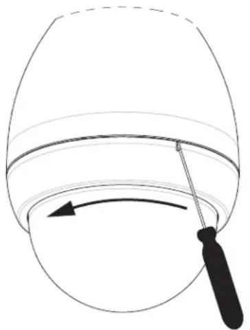
natural_image
Simple line drawing of a bucket with a tool, no text or symbols presentFigure 7.1 Pendant Bubble Release Opening
- Firmly rotate the bubble counterclockwise approximately 20 degrees until the bubble assembly releases from the Pendant Housing.
To remove the bubble from an in-ceiling housing
- Loosen the lockscrew (item 1 in the illustration below) in the trim ring using a P1 or smaller Phillips screwdriver until the bubble can rotate freely.
- Then rotate the bubble counterclockwise approximately 1/4 turn until it releases from the In-Ceiling Housing. See the figure below for an illustration.
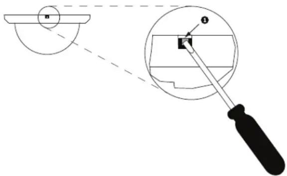
text_image
Technical diagram showing a tool interacting with a circular component, with labeled parts and dashed lines indicating alignment or measurement.Figure 7.2 Bubble Release Screw
7.2.2 Cleaning the Bubble Exterior
The exterior of the bubble is hard coated for extra protection. If cleaning becomes necessary, only use cleaning solutions and cloths suitable for cleaning safety glass lenses. Dry the bubble thoroughly with a dry nonabrasive cloth to prevent water spots. Never scrub the bubble with any abrasive material or cleaners.
Do Not:
- Do Not use abrasive or highly alkaline cleaners on the bubble.
- Do Not scrape the bubble with razor blades or other sharp instruments.
- Do Not use Benzene, Gasoline, Acetone, or Carbon Tetrachloride on the bubble.
- Do Not clean bubbles in the hot sun or on very hot days.
Index
A
alarm connectors 18
alarm inputs 69
dry contact relay 72
non-supervised 70
normally closed non-supervised 71
normally closed supervised 70
normally open non-supervised 71
normally open supervised 69
supervised 69
with in-ceiling mount 56
with parapet roof or pipe mounts 48
with pendant arm, corner or mast mount 18, 25, 30
alarm outputs 72
open collector output 72
with in-ceiling mount 56
with parapet roof or pipe mount 48
with pendant arm, corner or mast mount 18, 25, 30
attaching
cover door 36
in-ceiling mount 58
pendant arm 23
B
banding tool 14, 16, 26
Bilinx 61
biphase 17, 62, 63
BNC connector
with pendant arm, corner or mast mount 18, 29
with roof parapet or pipe mount 48
bracket assembly 54, 55
bubble 73
cleaning 73
handling 73
release aperture 74
C
cable compensation 61
cable standards 61
cables
copper 61
fiber optic 62
coaxial cable 61
communication protocol
RS232 64
control data I/O plug 17
copper wire 61
corner installation 16, 26
corner plate 16
cover door 36
D
daisy chaining 17, 64
dome cap 44
drywall ceiling 53
E
Ethernet 56
F
fiber optic 62
module 25
multimode 62
single mode 62
with pendant arm, corner or mast mount 18, 29
with roof parapet or pipe mount 39
fuse specifications 19
G
guy-wire 45
H
housing
securing 60
|
in-ceiling mount 52
attaching housing 58
interface box connections 57
parts 52
securing to ceiling 60
installing
in-ceiling mount 52
pendant arm, corner or mast mount 13
pipe interface board 49
pipe mount 45
roof parapet mount 42
tope-mounting flange 45
interface box 55, 57, 58
L
LTC 9230/01 43
M
mast installation 16, 26
mast plate 16
maximum distances 61
mount
in-ceiling 52
pendant arm, corner or mast 13
pipe 33
roof parapet 33
Mouting Plate 15, 26
N
NEMA Certification
for pendant arm, corner or mast mount 14
for roof parapet or pipe mount 34
non-supervised alarms 70
P
parapet arm
stabilizing 45
pendant
connector harness 26, 30
pendant arm
attaching to power supply box 23
pendant arm, corner or mast mount
mast plate 16
pendant assembly
attaching to pipe mount 50
pendant bubble
removing 73
pipe interface board 46, 49
pipe mount 33, 45
power supply box location 34
pole installation 16, 26
power supply
fuse specifications 19
with fiber optic model 51
power supply box 37
attaching to pendant arm 23
connections for pendant arm 20, 21
connections for roof parapet or pipe mount 33, 41, 51
daisy chaining 17
installing with in-ceiling mount 52
installing with pendant arm, corner or mast mount
15, 24
installing with roof parapet or pipe mount 35
locating for pendant arm, corner or mast mount 14
wiring for pendant arm, corner or mast mount 24
Pre-Comp 61
preparing
drywall ceiling 53
suspension ceiling 54
protocol
RJ45 56
R
relay 72
relay connectors 18
RJ45 56
roof parapet or pipe mount 33, 42
cover door 36
dome cap 44
fiber optic model 51
parts 33
power supply box location 34
wall bracket 43
wall mount bracket 42
routing wires
for in-ceiling mount 55
for pendant arm, corner or mast mount 16
for roof parapet or pipe mount 37
RS232 64
RS485 65
S
supervised 69
suspension ceiling 54
T
top-mounting flange 45
trim skirt 15
U
unshielded twisted pair 56
with in-ceiling mount 56
with pendant arm, corner or mast mount 18, 29
unshielded twisted pair (UTP) 62
V
VG4-A-9230 33, 42
VG4-ARMPLATE 15, 26
W
wall installation 16
wall mount template 15
for roof parapet or pipe mount 35
wire standards 61
wiring
for in-ceiling mount 52, 56
for interface box 55
for pendant arm, corner or mast mount 14
for pipe interface board 46
for roof parapet or pipe mount 39
power supply box 37
Bosch Security Systems, Inc.
850 Greenfield Road
Lancaster, PA 17601
U.S.A.
www.boschsecurity.com
© Bosch Security Systems, Inc., 2011