PA-19JK7 - TV Proview - Free user manual and instructions
Find the device manual for free PA-19JK7 Proview in PDF.

User questions about PA-19JK7 Proview
0 question about this device. Answer the ones you know or ask your own.
Ask a new question about this device
Download the instructions for your TV in PDF format for free! Find your manual PA-19JK7 - Proview and take your electronic device back in hand. On this page are published all the documents necessary for the use of your device. PA-19JK7 by Proview.
USER MANUAL PA-19JK7 Proview
PROVIEW User's Manual
PROVIEW
PROVIEW ELECTRONICS CO., LTD.
| ■ PRODUCT NO.: JK-195XU■ MODEL Number :■ SCALE: AS DRAWING■ PART NO.: 002-L00-■ SHEET 1 OF 1 | ■ Print Color: 4 Colour■ MATERIAL: Cover Page-200p Art PaperInner Page-100p Art Paper■ DIM. ARE IN MM■ EXTERIOR SIZE: 148(W)X210(H)TOL:0~+1 | ■ PM :■ SAFETY :■ SALES : | ■ DESIGNER :WENHUIJUAN■ APPROVED : |
FEDERAL COMMUNICATIONS COMMISSION (FCC) STATEMENT
This equipment has been tested and found to comply with the limits of a class B digital device. Pursuant to Part 15 of the FCC Rules. These limits are designed to provide reasonable protection against harmful interference in a residential installation. This equipment generates, uses and can radiate radio frequency energy and, if not installed and used in accordance with the instructions, may cause harmful interference to radio communications. However, there is no guarantee that interference will not occur in a particular installation. If this equipment does cause harmful interference to radio or television reception, which can be determined by turning the equipment off and on, the user is encouraged to try to correct the interference by one or more of the following measures:
- Reorient/Relocate the receiving antenna.
- Increase the separation between the equipment and receiver.
- Connect the equipment into an outlet on a circuit which is different from what the receiver is connected to.
- Consult the dealer or an experienced radio/TV technician for help.
For Canada:
This digital apparatus does not exceed the Class B limits for radio noise emissions from digital apparatus as set out in the Radio Interference Regulations of the Canadian Department of Communications.
This device complies with Canada ICES-003 Class B.
CAUTION
Changes or modifications not expressly approved by the manufacturer responsible for compliance could void the user authority to operate the equipment.
IMPORTANT SAFETY INSTRUCTIONS
WARNING
To reduce the risk of fire or electric shock, do not expose this equipment to rain or moisture.
CAUTION
RISK OF ELECTRIC SHOCK DO NOT OPEN

CAUTION: TO AVOID THE RISK OF ELECTRIC SHOCK, DO NOT REMOVE COVER (OR BACK).
NO USER-SERVICEABLE PARTS INSIDE.
REFER SERVICING TO QUALIFIED SERVICE PERSONNEL.

This symbol is intended to alert the user to avoid the risk of electric shock, do not disassemble this equipment by anyone except a qualified service personnel.

This symbol is intended to alert the user to the presence of important operating and maintenance instructions in the literature accompanying the appliance.
CAUTION
Use of controls or adjustments or performance of procedures other than those specified herein may result in hazardous radiation exposure.
IMPORTANT SAFETY INSTRUCTIONS
To prevent any injuries, the following safety precautions should be observed in the installation, use, servicing and maintenance of this equipment. Before operating this equipment, please read this manual completely, and keep it nearby for future reference.

natural_image
Symbolic icon of a person climbing a ladder inside a blue circle with a diagonal line (no text or symbols)■ Do not place the equipment on any uneven or unstable carts, stands, tables, shelves etc..
The equipment may fall, causing serious injuries to children or adults and serious damage to the equipment itself.
■ Use only a cart or stand recommended by the manufacturer. This equipment and recommended cart or stand should be handled with care. Quick stops, excessive force, and uneven surfaces may cause the equipment and recommended cart or stand to overturn.
natural_image
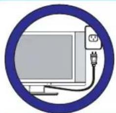
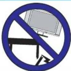
Illustration of a computer monitor connected to a plug, enclosed in a blue circular border (no text or symbols)- Do not disable the 3-wire grounding type plug. The grounding pin on the 3-prong plug is an important feature. Removing the grounding pin will increase the risk of damaging the equipment. If you can not fit the plug into the electrical outlet, contact an electrician to install a grounding outlet.
■ Always operate this equipment from the type of power source indicated on the rear of the serial/model plate.
natural_image
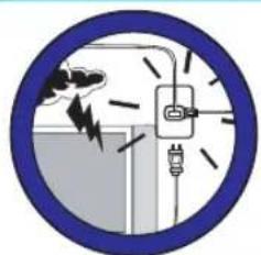
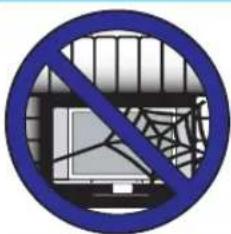
Circular diagram showing a lightning bolt striking a fuse and plug, enclosed in a blue border (no text or symbols)■ Never overload wall outlets and extensions.
■ Use and handle the power cord with care.
■ Do not place any heavy objects on the AC power cord.
- Do not pull the AC power cord. Do not handle the AC power cord with a wet hand.
■ Do not touch the power cord and antenna cable during lightning.
■ When the equipment has not been used for a long period of time, unplug it from the wall outlet.

■ Do not place, use or handle this equipment near water.
■ Never expose the equipment to liquid, rain, or moisture. Seek for service if any of the above is spilled into the equipment.

■ Do not expose the equipment to extreme temperatures or to direct sunlight, the equipment may overheat and can be damaged.
■ Do not install the equipment near any heat sources such as radiators, heat registers, stoves, or any other apparatus that might produce heat.
IMPORTANT SAFETY INSTRUCTIONS
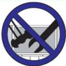
■ Do not attempt to service the equipment yourself.
■ Opening and removing the covers may expose you to dangerous voltage or any other hazards and may void your warranty. Refer service from qualified personnel.

■ Do not place or drop any other objects on top.
■ Do not insert anything into the ventilation holes of your equipment. Inserting any metal or flammable objects may result to fire or electric shock.
Do not place the equipment on uneven or unstable carts, stands, tables, shelves etc.. The equipment may fall, causing serious injuries to children or adults and serious damages to the equipment itself.
■ Always place the equipment on the floor or on a surface that is sturdy, level, stable and strong enough to support the weight of the equipment.
■ Do not block any ventilating openings, leave an open space around the equipment.
■ Never place the equipment :
- on a bed, sofa, rug, or any other similar surfaces;
- too close to drapes, curtains, in a bookcase, built-in cabinet, or any other similar places that may cause poor ventilation.

natural_image
Illustration of a hand holding a tool emitting smoke or vapor, enclosed in a blue circular border (no text or symbols)■ Always remove the cord from the outlet before cleaning the equipment.
■ Never use cleaners, harsh or abrasive chemicals or solvents on the equipment. Clean only with a dry, soft, lint-free cloth.
ANTENNA CONNECTION
EXAMPLE OF OUTDOOR ANTENNA GROUNDING
If an outdoor antenna is connected, follow the precautions below:
■ An outdoor antenna should not be located anywhere that can be in contact of overhead power lines, or any other electric light or power circuits.
■ When installing an outdoor antenna system, extreme caution should be taken to prevent contact with power lines. Direct contact with power lines may be fatal and should be avoided at all costs.
Section 810 of National Electrical Code (NEC) provides information with respect to proper grounding of the mast and supporting structure, grounding of the lead-in wire to an antenna discharge unit, size of grounding conductors, location of antenna discharge unit, connection to grounding electrodes, and requirements for the grounding electrode.
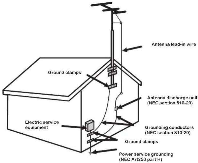
NEC : National Electrical Code
ANTENNA CONNECTION
Cable TV (CATV) Connection
NOTE TO CATV SYSTEM INSTALLER
This reminder is provided to call the CATV system installers attention to Article 820-40 of the National Electrical Code (NEC) that provides guidelines for proper grounding and, in particular, specifies that the cable ground shall be connected to the grounding system of the build in g ac cu ra te ly, or as close to the point of cable entry as possible. Use of this TV for other than private viewing of programs broadcasted on UHF, VHF or transmitted by cable companies for the use of the general public may require a u t h o r i z a t i o n f r o m t h e b r o a d c as t/ c a b l e c o m p a n y, and/or program owner.
A 75 - oh m co axial cable connector is built into the set for easy hook p. When conne ct in g the 75 - oh m co axial cable to the set, place the 75 -ohm cable into the AN T. ter mi na l.
■ Some cable TV companies offer premium pay channels. Since the signals of these premium pay channels are scrambled, a cable TV converter/descrambler is generally provided to the subscriber by the cable TV company.
This converter/descrambler is necessary for normal viewing scrambled channels.
(Set your TV to channel 3 or 4, typically one of these channels are used.
If this is unknown, consult your cable TV company.)
For more specific instructions on installing cable TV, consult your cable TV company,
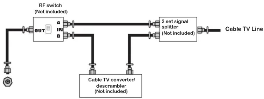
One possible method of utilizing the coverter/descrambler provided
by your cable TV company is explained below.
flowchart
graph LR
    A["RF switch (Not included)"] --> B["OUT"]
    B --> C["A"]
    B --> D["B"]
    C --> E["2 set signal splitter (Not included)"]
    D --> E
    F["Cable TV converter/descrambler (Not included)"] --> E
    G["Cable TV Line"] --> E
Please note: the RF switch is required to provide two inputs (A and B). (not included) A position on the RF switch (not included); you can view all unscrambled channels by using the TV channel keys.
B position on the RF switch (not included); you can view all scrambled channels via the converter/descrambler by using the converter channel keys.
ANTENNA CONNECTION
ANTENNAS
The antenna requirements for good color TV reception are more important than those of a black & white TV reception. For this reason, a good quality outdoor antenna is strongly recommended.
The following is a brief explanation of the type of connection that is provided with the various antenna systems.
A 75-ohm system is generally a round cable with NTSC connector that can easily be attached to a terminal without tools (not included).
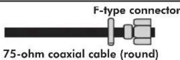
A 300-ohm system is a flat twin-lead cable that can be attached to a 75-ohm terminal through a 300-75-ohm adapter (not included).

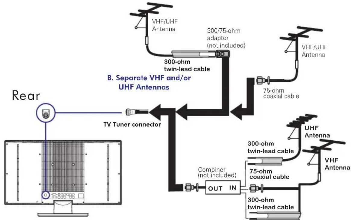
OUTDOOR ANTENNA
■ Use one of the following two diagrams when connecting a n outd oor ant enna.
A: Use a VHF/U HF com bi nat ion outdo or ante nna. B: Use a separate VHF and /or UHF outd oor ant enna.
Connect the out do or ante nna cable lead -in to the ANT. term inal locate d on t he rear of t he equi pment.
A. Combination VHF/UHF antenna
flowchart
graph TD
    A["Rear"] --> B["TV Tuner connector"]
    B --> C["300-ohm twin-lead cable"]
    C --> D["300/75-ohm adapter (not included)"]
    D --> E["75-ohm coaxial cable"]
    E --> F["VHF/UHF Antenna"]
    F --> G["UHF Antenna"]
    G --> H["300-ohm twin-lead cable"]
    H --> I["75-ohm coaxial cable"]
    I --> J["300-ohm twin-lead cable"]
    J --> K["OUT IN"]
    K --> L["Combiner (not included)"]
    L --> M["TV Tuner connector"]
    style A fill:#f9f,stroke:#333
    style B fill:#ccf,stroke:#333
    style C fill:#cfc,stroke:#333
    style D fill:#fcc,stroke:#333
    style E fill:#cff,stroke:#333
    style F fill:#ffc,stroke:#333
    style G fill:#fcc,stroke:#333
    style H fill:#ffc,stroke:#333
    style I fill:#fcc,stroke:#333
    style J fill:#ffc,stroke:#333
    style K fill:#fcc,stroke:#333
    style L fill:#cff,stroke:#333
    style M fill:#ffc,stroke:#333
CONTENT
PREPARATION 9
Features 9
Package Contents 10
LCD TV 11
Front View 11
Rear View 12
Remote Control 13
Using your LCD TV.... 15
INSTALLATION 16
Connecting a TV Cable or an Antenna 16
Connecting a DVD Player 17
Connecting a VCR & a Video Camera 18
Connecting a TV Box and Satellite Receiver 19
USING THE FEATURES 20
Basic Operation 20
OSD Menu Operation 21
Video 21
Audio 22
Parental....23
Setup 24
TROUBLESHOOTING....27
SPECIFICATION 28
PREPARATION
Congratulations on the purchase of your new High Def inition Compatible Television. In order to maximize the potential of this television, you must use it in conjunction with a High Definition Signal Source, utilizing a proper High Definition receiving unit (of ten referred to as a “set-top” box). Only “true” High Def inition transmitted video will yield optimum picture quality. Please contact your cable or satellite provider for more information on how to receive High Definition programming.
Features
Features
High Brightness / Contrast Image
VGA Support:
720x400/70Hz\~1792x1344/60Hz
● Supports ED and HD Input Signals 480i/480p/720p/1080i
- Multimedia Jack
S-Video Jack
HD Component Video Jack (YPbPr)
PC Jack
A/V Jack
Auto-channel setup
181-Channel CATV Tuner
Sleep-Timer
User selectable color temperature settings
MTS (Multi-Channel Television Sound)
V-Chip and Closed Captioning
Enhance audio processing
Built-In CATV tuner
Faroudja DCDI Edge Processing

by FAROUDJA
"DCDi® by Faroudja" is a registered trademark of Genesis Microchip Inc.
Package Contents
Once you open the box, make sure all of the following contents are included. If you're missing any items, please return this product to the original place of purchase.
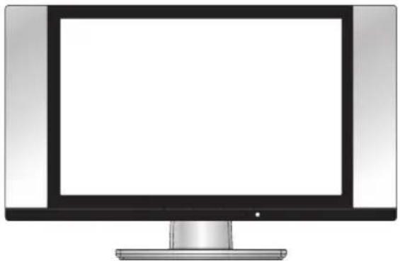
natural_image
Illustration of a flat-screen computer monitor with blank screen (no text or symbols)LCD TV
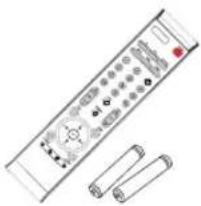
natural_image
Illustration of a remote control with two cylindrical batteries (no text or symbols)Remote control/AAA batteries
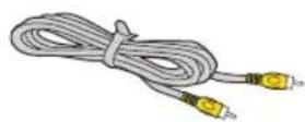
Video Cable
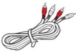
natural_image
Illustration of a coiled cable with three red audio/video cables (no text or symbols)Audio Cable

natural_image
Black-and-white illustration of a coiled electrical cable with two connectors (no text or symbols)Power Cord

User Guide

Quick Set Up Guide
These items are all you need to set up and operate the LCD TV in its basic configuration.
*Most devices (VCRs, DVD player, etc.) come with the necessary cable for connection. If you want to set up a complex system, you may need to buy extra cable, connector, etc.
LCD TV
Front View
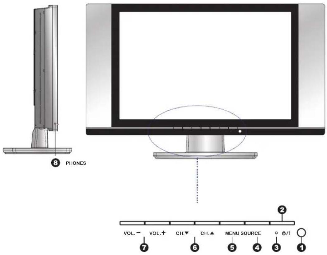
ITEM DESCRIPTION
1 IR Infrared Receiver (IR)
2 POWER Turns the LCD TV on and off.
3 LED The LED light indicates when the LCD TV is activated (green light indicates on and amber indicates off).
4 SOURCE Chooses from different input signal sources.
5 MENU Press MENU to display the OSD (on screen display). Press again to turn the OSD off.
6 CHANNEL
Seans up and down through channels.
Selects sub-menu items when in the OSD mode.
7 VOLUME Adjusts the volume up and down. Changes settings for items and the value for items when in the OSD mode.
8 PHONES Connects to either headphones or the Line-IN of your audio equipment.
LCD TV
Rear View
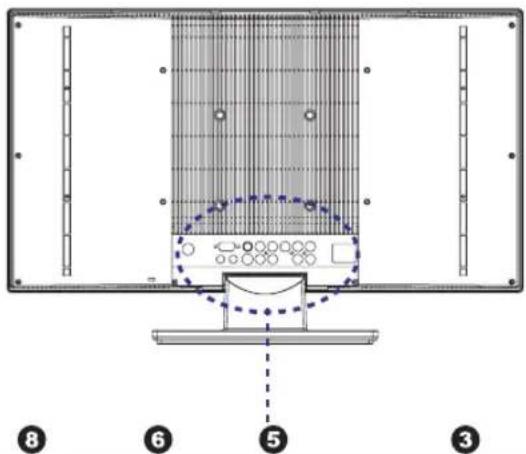
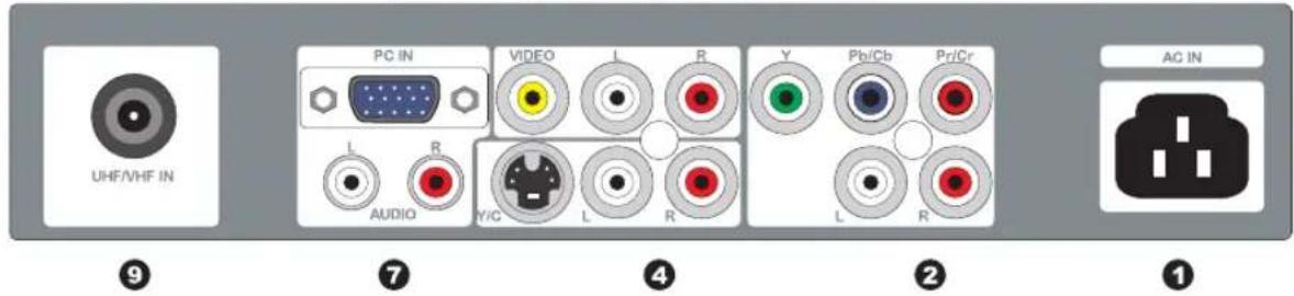
ITEM DESCRIPTION
1 AC IN Connects the AC power cord.
| 2 AUDIO IN 1 | Connects to the audio or video equipment with left and right audio output jacks of the component (Y, Pb/Cb, Pr/Cr). |
| 3 COMPONENT | Connects to the component (Y, Pb/Cb, Pr/Cr) video jacks on your DVD player, HDT V Tuner source, or video equipment. |
| 4 S-VIDEO | Connects to the S-VIDEO output jacks and Audio output jacks on your video equipment. |
| 5 AUDIO IN 2 | Connects to the audio or video equipment with left and right audio output jacks of the Composite or S-V ideo. |
| 6 VIDEO | Connects to the composite Video output jack on your video equipment. |
| 7 PC AUDIO IN | Connects the audio input jack of the satellite receiver or other AV equipment. |
| 8 PC IN | Connects the satellite receiver or other AV equipment with D-Sub connector. |
| 9 RF/ANT. The RF input that connects to your VHF/UHF antenna or cable. | |
Remote Control
1 POWER
Turns the LCD TV on and into standby mode.
2 PC
Press to select PC mode.
3 MTS
Selects the Multi-channel TV Sound. Options: Stereo, SAP, and Mono.
4 CAPTION
To select the C.C. Mode to be ON or OFF.
5 MUTE
Mutes and restores your LCD TV sound.
6 SLEEP
Sets the sleep timer.
7 P.SIZE
Selects from the following modes settings: 4:3, 16:9.
8 0-9 and ENTER
Select and switch to a channel using 0-9 and ENTER buttons.
9 JUMP
Switches back and forth between the current and previous channels.
10 CH. +/-
Changes the channels up and down.
11 VOL. +/-
Adjusts the volume.
12 INFO
Displays information on the LCD TV screen such as channel and channel label.
13 SOURCE
Selects from different input signal source: TV, AV1(VIDEO), AV2(S-VIDEO), AV3(HDTV), AV4(VGA).
14 EXIT
Exits the OSD menu (on-screen display).
15 MENU
Displays on screen menu one by one. Exits the current menu.
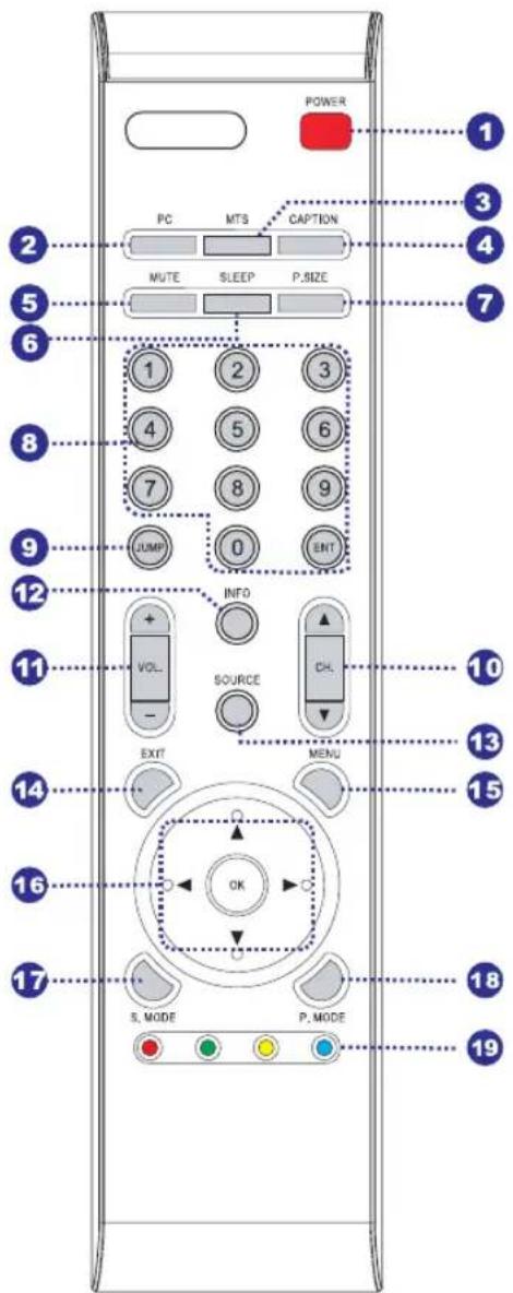
16
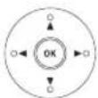
Allows you to move, select and set up the OSD options.
17 SOUND MODE
Selects sound mode: Custom, Live, POP, Rock.
18 PIC MODE
Selects picture mode: Custom, Vivid, Standard, Mild.
19 NO FUNCTIONS
Remote Control
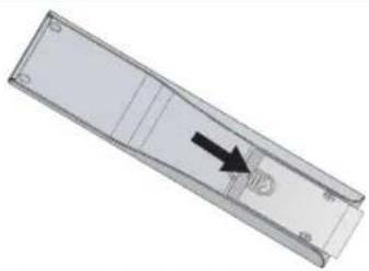
Installing the batteries in your remote control
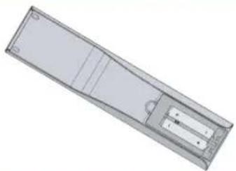
1
Pull the tab of the back cover and pull up on the cover to open the battery compartment of the remote control.
natural_image
3D rendering of a rectangular mechanical part with an arrow pointing to a small component (no text or symbols visible)2
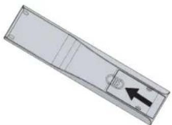
Insert two A A A size bat teries. Make sure to match the (+) and (-) ends of the batteries with the (+) and (-) ends indicated in the batter y compar tment.
natural_image
3D rendering of a rectangular electronic device with internal components and mounting holes (no text or symbols visible)3
Align the lower tabs of the back cover to the remote control and snap the cover into place.
natural_image
3D diagram of a rectangular panel with internal compartments and a black arrow pointing to a circular component (no text or symbols)Note :
Do not use caustic cleaners( porcelain, stainless steel, toilet, or oven cleaner, etc...). You may cause damage to your remote control.
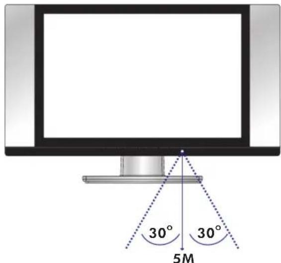
Effective range
Your remote control can be activated from up to the LCD TV 5m away, if pointed directly in front of the device.
Using your LCD TV
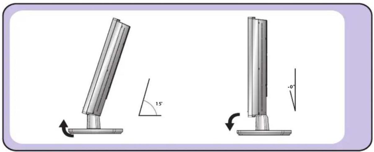
1 You may adjust the tilt angle of the LCD TV about +15 deg. / -0 deg.
natural_image
Technical illustration of two mechanical components with angular and linear measurements, no text or symbols present2 Always turn the LCD TV off when the LCD TV is not in use for a long period. The Power button is only used for switching the LCD TV into standby mode, it does not disconnect the device from the main power source. To completely disconnect from the main power, please switch off the unit and remove the power plug from the socket.
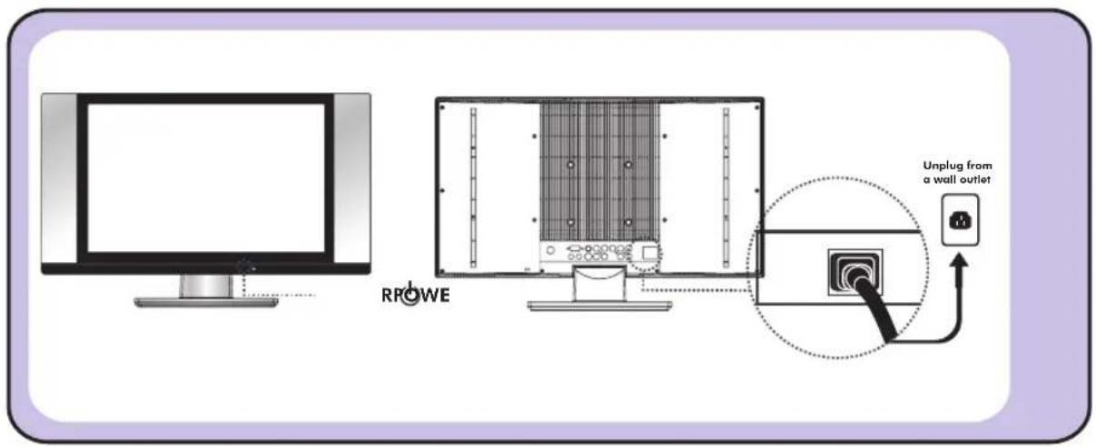
INSTALLATION
Refer to the owner's manual of the external equipments to be connected. When connecting external equipments, do not connect any AC power cords to wall outlets until you have completed all the connections.
Connecting a TV cable or Antenna
Basic Connection: Connecting cable or an antenna.
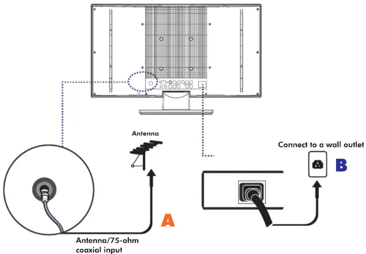
A: Use a supplied antenna cable to connect the VHF/UHF to your LCD TV.
2 B: Connect all AC power sources before turning on the power for the LCD TV or other connected equipments.
3 Press the POWER button to turn on your LCD TV.
4 Press the TV button directly enter TV mode.
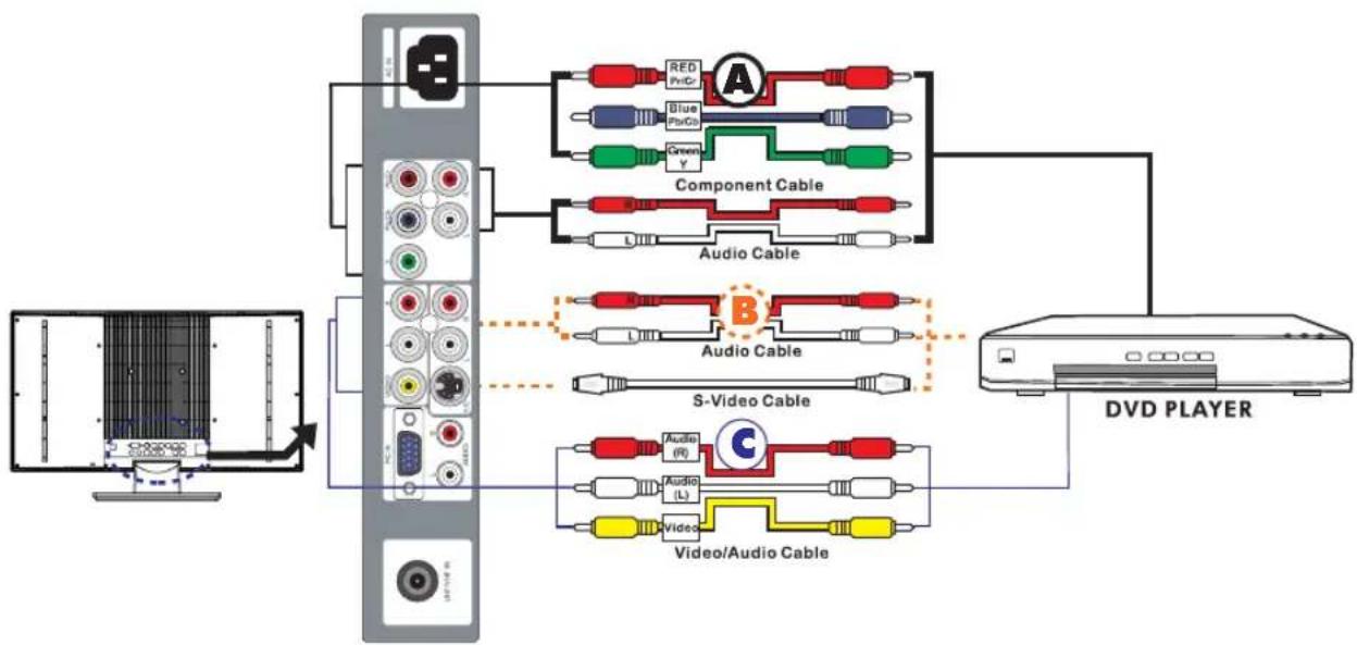
Connecting a DVD Player
For best picture quality, if your equipment has (Y Pb/Cb Pr/Cr) video output, please use component cable instead of a standard video or S-video cable.
flowchart
graph TD
    A["CD/DVD Player"] --> B["Component Cable"]
    A --> C["Audio Cable"]
    A --> D["Video/Audio Cable"]
    B --> E["Red Pn/Cr"]
    B --> F["Blue Pb/Cs"]
    B --> G["Green Y"]
    C --> H["L"]
    D --> I["Audio (R)"]
    D --> J["Audio (L)"]
    D --> K["C"]
    style A fill:#f9f,stroke:#333
    style B fill:#ccf,stroke:#333
    style C fill:#cfc,stroke:#333
    style D fill:#fcc,stroke:#333
1 METHOD A (AV3)
Use a Component cable to connect the Y/Pb(Cb)/Pr(Cr) jacks on the DVD player to your LCD TV. Use an audio cable to connect the DVD's audio jacks to your LCD TV.
METHOD B (AV2)
Use an Audio cable to connect the DVD's audio output jacks to your LCD TV. Use a S-Video cable to connect your LCD TV and DVD player.
METHOD C (AV1)
Use an A/V cable to connect the DVD's composite output jacks to your LCD TV.
2 Connect all power sources before turning on the power for the LCD TV or other connected equipments.
3 Press the POWER button to turn on your LCD TV.
4 To watch DVD, press the SOURCE button to select AV1, AV2 or AV3.
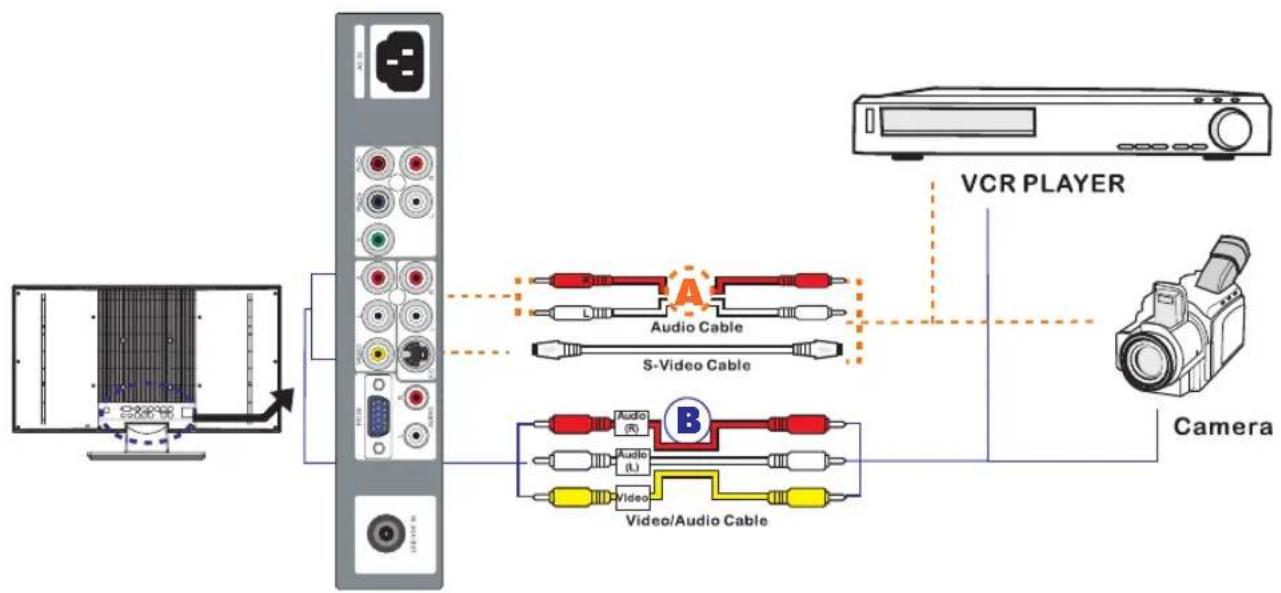
Connecting a VCR & a Video Camera
flowchart
graph TD
    A["Camera"] --> B["VCR PLAYER"]
    B --> C["Audio Cable"]
    C --> D["S-Video Cable"]
    D --> E["Video/Audio Cable"]
    E --> F["Audio (R)"]
    E --> G["Audio (L)"]
    E --> H["Video"]
    style A fill:#f9f,stroke:#333
    style B fill:#ccf,stroke:#333
    style C fill:#cfc,stroke:#333
    style D fill:#fcc,stroke:#333
    style E fill:#cff,stroke:#333
    style F fill:#ffc,stroke:#333
    style G fill:#ffc,stroke:#333
    style H fill:#ffc,stroke:#333
1 METHOD A (AV2)
Use an Audio cable to connect the VCR's/VIDEO CAMERA's audio output jacks to your LCD TV.
Use a S-Video cable to connect your LCD TV and VCR player/VIDEO CAMERA.
METHOD B (AV1)
Use an A/V cable to connect the VCR's/VIDEO CAMERA's. composite output jacks to your LCD TV.
2 Connect all power sources before turning on the power for the LCD TV or other connected equipments.
3 Press the POWER button to turn on your LCD TV.
4 To watch VCR or VIDEO CAMERA, press the SOURCE button to select AV1 or AV2.
Note: Not all cameras have the ability to connect to a TV. Please check your video camera user guide for compatibility.
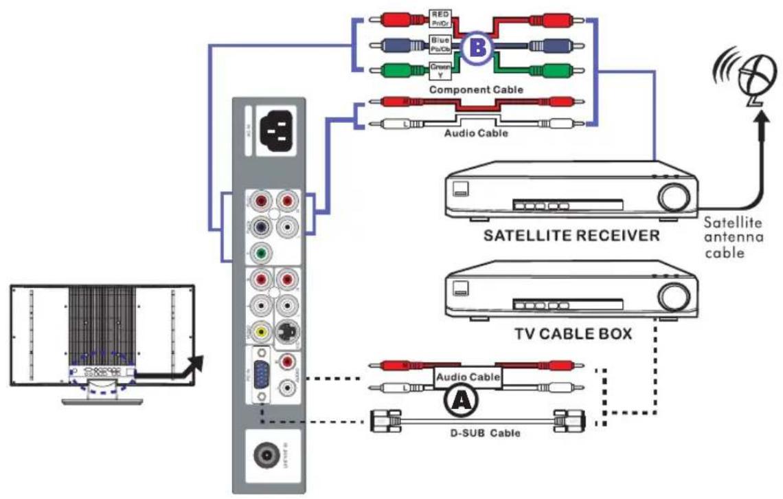
Connecting a TV Box and Satellite Receiver
flowchart
graph TD
    A["TV CABLE BOX"] --> B["SATELLITE RECEIVER"]
    B --> C["Component Cable"]
    C --> D["Audio Cable"]
    D --> E["SATELLITE RECEIVER"]
    E --> F["Satellite antenna cable"]
    F --> G["Radio Station"]
    H["Computer"] --> I["Switch"]
    style A fill:#f9f,stroke:#333
    style B fill:#ccf,stroke:#333
    style C fill:#cfc,stroke:#333
    style D fill:#fcc,stroke:#333
    style E fill:#cff,stroke:#333
    style F fill:#ffc,stroke:#333
    style G fill:#cfc,stroke:#333
    style H fill:#fcc,stroke:#333
1 METHOD A (AV4)
Use a D-SUB cable to connect the TV Cable Box D-SUB connector to your LCD TV. Use an Audio cable to connect the TV Cable Box and your LCD TV.
METHOD B (AV3)
Use a component cable to connect the Y/Pb(Pb)/Pr(Cr) jacks on the satellite receiver to your LCD TV. Use an Audio cable to connect the Satellite Receiver audio jacks to your LCD TV.
2 Connect all power sources before turning on the power for the LCD TV or other connected equipments.
3 Press the POWER button to turn on your LCD TV.
4 To watch programs via satellite receiver, or to watch TV via TV cable box, press the SOURCE button to select AV3 or AV4.
USING THE FEATURES
Basic Operation
Turning the TV On and Off
1 After connecting a CATV / antenna to your LCD TV, and connecting the unit to a power source, an amber LED light indicates the LCD TV is activated.
2 Press the POWER button, the LED green light indicates on.
3 Press the POWER button, the LED amber light indicates off.
Select Source
Press the SOURCE button to display the selection signal on the screen.
Select TV Channel
1 Press the CH+/- button on the remote control and the CHANNEL ▲/▼ button on the LCD TV to select channel.
2 Press the 0\~9 buttons then press the ENTER button to input the channel No. and enter into the selection channel No.
3 Press the JUMP button on the remote control to swap the channel between the current channel No. and the previous channel No.
Adjusting the Volume
Press the VOL +/- button on the remote control or the VOLUME +/- button on the LCD TV to adjust the volume.
To Mute the Sound
1 Press MUTE to mute the sound.
2 To turn mute off, press the MUTE button again, or simply press the VOL +/- buttons.
Sleep Timer
System to enter Power Down Mode in 20 Sec
Press the SLEEP button continuously to select the sleep time ranging from OFF, 15, 30, 45, 60, 90 and 120 minutes; when the LCD TV has reached the set time, it will automatically turn off. If the TV has no input signal, the screen will display a blue screen with a NO Signal message, The TV will automatically switch to standby mode after 15 minutes.
OSD Menu Operation
flowchart
graph TD
    A["Video"] --> B["PIC Mode"]
    C["Audio"] --> D["Brightness"]
    E["Parental"] --> F["Contrast"]
    G["Setup"] --> H["Hue"]
    I["Saturation"] --> J["Sharpness"]
    K["Color Temp."] --> L["Advanced"]
| The main menu provides access to the following menus: | |
| Video | Adjust picture setting such as brightness, contrast,saturation and color temp. |
| Audio | Adjust sound option and effects. |
| Parental | Allows you to set up the TV to block programs according to their content and rating levels. |
| Setup | Set up miscellaneous fetures. |
2 Press the MENU button on the remote control. The main menu will appear on the screen.
3 Use ▲/▼ to highlight your main menu option, then press OK to enter your selected option. Use ▲/▼ to highlight an option of the sub-menu. Use ◀/▶ to change the value of the item. Press the EXIT button to exit MENU.
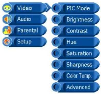
Video
Use this Video setting menu to adjust the picture quality which best corresponds to your viewing requirements. The Video Menu includes the following options:
flowchart
graph TD
    A["Video"] --> B["PIC Mode"]
    C["Audio"] --> B
    D["Parental"] --> B
    E["Setup"] --> B
    B --> F["Custom"]
    B --> G["Vivid"]
    B --> H["Standard"]
    B --> I["Mild"]
| OPTION DESCRIPTION | |
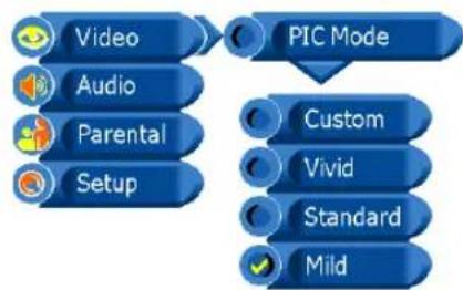
| PIC Mode | Custom: Select for user's settings. |
| Vivid: Select for enhanced picture contrast and sharpness. | |
| Standard: Select for standard picture settings. Recommended for home entertainment. | |
| Mild: Select for mild picture settings. | |
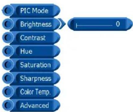
| Brightness | Adjust to brighten or darken the picture. |
| Contrast | Adjust the difference between the brightest and darkest regions of the picture. |
| Hue | Adjust to increase or decrease the green tint. |
| Saturation | Controls the color intensity. |
| Sharpness | Adjust to sharpen or soften the picture. |
flowchart
graph TD
    A["PIC Mode"] --> B["0"]
    C["Brightness"] --> B
    D["Contrast"] --> B
    E["Hue"] --> B
    F["Saturation"] --> B
    G["Sharpness"] --> B
    H["Color Temp."] --> B
    I["Advanced"] --> B
Video
flowchart
graph TD
    A["Video"] --> B["Color Temp."]
    C["Audio"] --> B
    D["Parental"] --> B
    E["Setup"] --> B
    B --> F["Standard"]
    B --> G["Warm"]
    B --> H["Cool"]
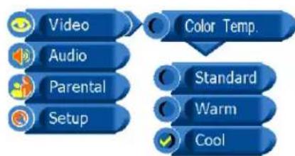
OPTION DESCRIPTION
Color Temp. Standard: Select to give the white colors a neutral tint.
Warm: Select to give the white colors a reddish tint.
Cool: Select to give the white colors a bluish tint.
flowchart
graph TD
    A["Video"] --> B["Advanced"]
    C["Audio"] --> B
    D["Parental"] --> B
    E["Setup"] --> B
    F["Auto"] --> B
    G["Position"] --> B
    H["Phase"] --> B
    I["Clock"] --> B
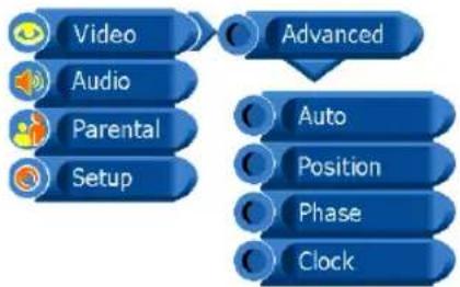
Advanced (VGA Mode only) Auto : Allows you to select the image auto adjust to be Yes or No.
Position Allows you to move the position of the picture in the window.
Phase Increase the focus clarity in the picture and image satbility. (Available only for PC input.)
Clock Adjusts the horizontal size of the picture.
Audio
Use this AUDIO setting menu to adjust the sound quality which best corresponds to your listening requirements.
flowchart
graph TD
    A["Video"] --> B["Audio"]
    B --> C["Parental"]
    C --> D["Setup"]
    E["Volume"] --> F["Bass"]
    G["Treble"] --> H["Balance"]
    I["Surround"] --> J["Sound Mode"]
    K["MTS"] --> L["MTS"]
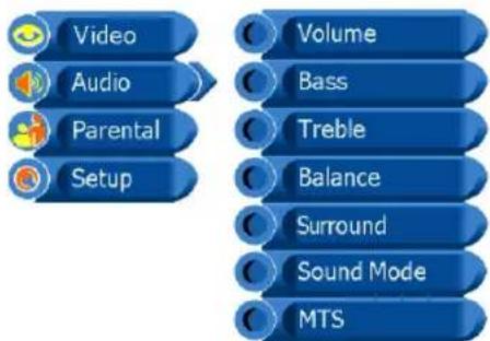
OPTION DESCRIPTION
| Volume | Allows you to adjust the volume add or subtract. |
| Bass | Adjust low frequency audio response. |
| Treble | Adjust high frequency audio response. |
| Balance | Adjust to emphasize left or right speaker balance |
flowchart
graph TD
    A["Video"] --> B["Audio"]
    B --> C["Parental"]
    C --> D["Setup"]
    E["Sound Mode"] --> F["Custom"]
    F --> G["Live"]
    G --> H["POP"]
    H --> I["Rock"]
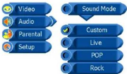
Surround Allows you to select the surround to be ON or OFF.
Sound Mode Allows you to select the sound mode to Custom, Live, POP, and Rock.
flowchart
graph TD
    A["Video"] --> B["Audio"]
    B --> C["Parental"]
    C --> D["Setup"]
    E["MTS"] --> F["Mono"]
    F --> G["Stereo"]
    G --> H["SAP"]
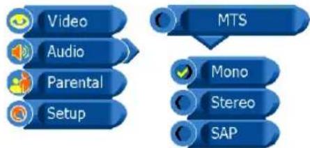
MTS Allows you to listen to high-fidelity stereo sound while watching TV.
STEREO: You can enjoy your TV in stereo mode. SAP: You can enjoy a second audio program from the speakers while watching a scene in the original program.
Mono: If the stereo sound is noisy, select Mono to reduce the noise.
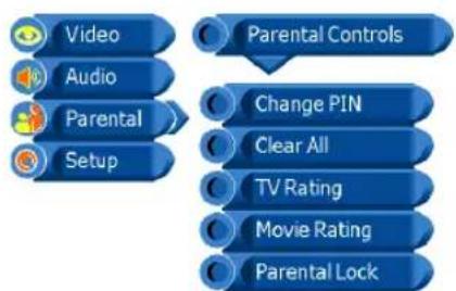
Parental
The Parental settings allows you to set up the TV to block programs according to their content and rating levels.
flowchart
graph TD
    A["Video"] --> B["Audio"]
    B --> C["Parental"]
    C --> D["Setup"]
    D --> E["Parental Controls"]
    E --> F["Enter PIN ----"]
    F --> G["Correct PIN"]
    G --> H["Continue"]
flowchart
graph TD
    A["Video"] --> B["Setup"]
    C["Audio"] --> B
    D["Parental"] --> B
    E["Parental Controls"] --> B
    F["Enter PIN"] --> B
    G["Invalid PIN"] --> B
    H["Back"] --> B
flowchart
graph TD
    A["Video"] --> B["Audio"]
    B --> C["Parental"]
    C --> D["Setup"]
    D --> E["Parental Controls"]
    E --> F["Change PIN"]
    F --> G["New PIN"]
    G --> H["Re-Enter PIN"]
flowchart
graph TD
    A["Video"] --> B["Audio"]
    B --> C["Parental"]
    C --> D["Setup"]
    E["Parental Controls"] --> F["Change PIN"]
    F --> G["Clear All"]
    G --> H["TV Rating"]
    H --> I["Movie Rating"]
    I --> J["Parental Lock"]
flowchart
graph TD
A["Video"] --> B["Audio"]
B --> C["Parental Setup"]
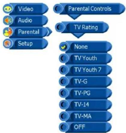
D["Parental Controls"] --> E["TV Rating"]
E --> F["None"]
F --> G["TV Youth"]
G --> H["TV Youth 7"]
H --> I["TV-G"]
I --> J["TV-PG"]
J --> K["TV-14"]
K --> L["TV-MA"]
L --> M["OFF"]
| OPTION | DESCRIPTION |
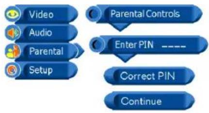
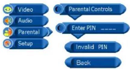
| Enter PIN | You can set up the TV to block program by entering your four digit password.(The default factory password is “1111”.) |
| After enter the correct PIN, the Parental Controls menu will display “Correct PIN” and “Continue”. If enter incorrect PIN, the menu will display “Invalid PIN” and “Back”. | |
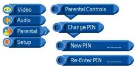
| Change PIN | Press the 0~9 buttons to enter a new four-digit password. To Confirm and enter a new four-digit password again. |
| Clear All | Allows you to clear all the parental settings |
| TV Rating | None Allows you to select the Block TV None Rating to be OFF or ON. |
| TV Youth All children | |
| TV Youth 7 Directed to children age 7 and older | |
| TV-G General Audience | |
| TV-PG Parents Guidance suggested | |
| TV-14 Parents strongly cautioned | |
| TV-MA Mature Audience only | |
| OFF Allows you to clear all the TV Rating settings |
Parental
| OPTION DESCRIPTION | |
| Movie Rating | NA Allows you to select the BlockMPAA Unrated to be OFF or ON. |
| G General Audiences. Movie is appropriate for all ages. | |
| PG Parental Guidance Suggested.May contain material not suited for younger viewers | |
| PG 13 Contains content that may not be appropriate for viewers under the age of 13. | |
| R Restricted. Contains adult content, no one under 17 admitted without parent. | |
| NC-17 No one 17 and under admitted. | |
| X Only for Adult. | |
| OFF Allows you to clear all the Movie Rating settings | |
| Parental Lock | Allows you to select the Parental to be OFF or ON. |
Setup
Use this Setup setting menu to set up some features: Tuner/Channel, Language etc.
| Video | Channel |
| Audio | Language |
| Parental | OSD Time |
| Setup | Sleep Time |
| Reset | |
| CC Mode |
1
| Video | Channel |
| Audio | Auto Search |
| Parental | Channel System |
| Setup | Channel Name |
| Fine Tune | |
| Skip |
2
| Video | Channel |
| Audio | Auto Search |
| Parental | |
| Setup | Start |
OPTION DESCRIPTION
Channel
(TV Mode Only)
Auto Search
All stations that can be received are stored by this method. It is recommended that you use auto Search during installation of this set.
- Press the MENU button and then use ▲/▼ button to select the Setup menu.
Press the ▶ button and then use OK button to select Channel.
- Press the ▶ button to select Auto Search and then use OK button to select Start.
Setup
3

Auto Search +
CH No 0
4

Auto Search Auto Tuning Completed

Video
Audio

Parental

Setup

Channel

Channel System

Air

Cable-STD

Cable-HRC

Cable-IRC

Video

Audio

Parental

Setup

Channel

Channel Name

Channel Name
ABCDE123

Video

Audio

Parental

Setup

Language

English

Français

Español

Video

Audio

Parental

Setup

OSD Time

5 sec.

10 sec.

15 sec

20sec

25 sec.

30 sec
-
to begin auto search.
-
auto search completed. All receivable stations are stored.
OPTION DESCRIPTION
Channel System
Allows you to select the tuner input source to be Air, Cable-STD, Cable-HRC or Cable -IRC.
Channel Name
Allows you to edit the channel name.
Fine Tune Allows you to adjust the fine tune level by hand if signal is too weak or picture is blurry.
Skip Allows you to skip the present channel.
Language
Select to display all on-screen Settings in your language of choice: English, Spanish, and French.
OSD Time
Allows selection of the display time of the on-screen menu: 5 sec, 10 sec, 15 sec, 20 sec, 25 sec, and 30 sec.
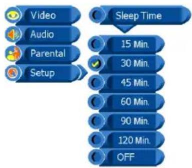
Setup
flowchart
graph TD
    A["Video"] --> B["Audio"]
    B --> C["Parental"]
    C --> D["Setup"]
    D --> E["Sleep Time"]
    E --> F["15 Min."]
    E --> G["30 Min."]
    E --> H["45 Min."]
    E --> I["60 Min."]
    E --> J["90 Min."]
    E --> K["120 Min."]
    E --> L["OFF"]
OPTION DESCRIPTION
Sleep Time
Sets up a certain time to shut off automatically: OFF/15/30/45/60/90/120 minutes.
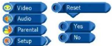
Reset
Allows you to restore the factory settings.
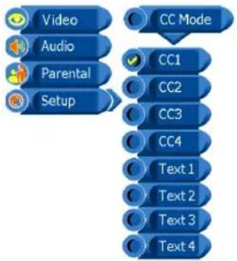
flowchart
graph TD
    A["Video"] --> B["Setup"]
    C["Audio"] --> B
    D["Parental"] --> B
    E["Setup"] --> F["CC Mode"]
    G["CC1"] --> H["Text 1"]
    I["CC2"] --> J["Text 2"]
    K["CC3"] --> L["Text 3"]
    M["CC4"] --> N["Text 4"]
CC Mode
Allows you to select the CC mode to be CC1, CC2, CC3, CC4, TEXT1, TEXT2, TEXT3, TEXT4.
TROUBLESHOOTING
Beforeconsultingservicepersonnel, check the following chart for a possible cause of the trouble you are experiencing and for a solution.
PROBLEMSOLUTION
| TVwillnotturnon | □ Makesurethepowercordispluggedin.□ Thebatteriesintheremotecontrolmaybeexhausted.Replacethebatteries. |
| Nopicture,nosound | □ ChecktheinterfacecablebetweenTVandantenna/cableTV.□ Pressthebuttonontheremote.Power□ PressthebTVSOURCEEmote,thenpressthebuttonrepeatedlytoselecttheconnectedvideosources. |
| Poorpicture,soundOK | □ ChecktheinterfacecablebetweenTVandantenna/cableTV.□ Tryanotherchannel,thestationmayhavebroadcastdifficulties.□ AdjusttheBrightness/ContrastoptionsinthelmageMVideo |
| PictureOK,Poorsound | □ SoundmaybemuteMUTEsthebuttonontheremote.□ Pressthe TVbuttonontheremote,thenpressthe buttonoincreasethevolume. VOL.+ |
| Audionoise | □ MoveanyinfraredequipmentawayfromtheTV. |
SPECIFICATIONS
| Model | PA-19JK7 |
| Panel System | 19 inch LCD panel |
| Display Resolution | 1440 pixels (horizontal) x 900 pixels (vertical) |
| Television System | NTSC |
| Brightness | 450 cd/m^2 |
| Contrast Ratio | 500:1 |
| Inputs/Output | |
| Composite Video In | 1 |
| S-Video In | 1 |
| PC | 1 |
| PC Audio In | 1 |
| Audio In | 3 |
| TV | 1 |
| Speaker Out | 3 W+3 W |
| Power Source(MAX) | 100-240 V~, 50/60 Hz, 50 W |
| Dimension( W x D x H) | 22.6 inch x 6.7 inch x 14.6 inch |
| Weight(Net) | 12.33 LBS |
Display Mode
For the display modes listed below, the screen image has been optimized during manufacture.
VGA TIMING
| Dot X Line | Horizontal Frequency(kHz) | Vertical Frequency(Hz) |
| 640 x 480 31.46 | 59.94 | |
| 640 x 480 37.86 | 72.80 | |
| 640 x 480 37.50 | 75.00 | |
| 720 x 400 31.46 | 70.40 | |
| 800 x 600 | 35.15 56.25 | |
| 800 x 600 | 37.87 | 60.31 |
| 800 x 600 | 48.07 | 72.18 |
| 800 x 600 | 46.87 | 75.00 |
| 1024 x 768 | 35.52 | 86.95 |
| 1024 x 768 | 48.36 | 60.00 |
| 1024 x 768 | 56.47 | 70.06 |
| 1024 x 768 | 60.02 | 75.02 |
| 1152 x 864 | 67.50 | 75.00 |
| 1280 x 960 | 60.00 | 60.00 |
| 1280 x 1024 | 63.98 60.02 | |
| 1280 x 1024 | 79.97 75.02 | |
| 1440 x 900 | 55.93 59.88 | |
| 1440 x 900 | 70.63 | 74.98 |
| 1600 x 1200 | 75.00 60.00 | |
| 1600 x 1200 | 81.25 65.00 | |
| 1600 x 1200 | 87.50 70.00 | |
| 1600 x 1200 | 93.75 75.00 | |
| 1792 x 1344 | 83.64 60.00 |