RS500A-E9-PS4 - Server ASUS - Free user manual and instructions
Find the device manual for free RS500A-E9-PS4 ASUS in PDF.

User questions about RS500A-E9-PS4 ASUS
0 question about this device. Answer the ones you know or ask your own.
Ask a new question about this device
Download the instructions for your Server in PDF format for free! Find your manual RS500A-E9-PS4 - ASUS and take your electronic device back in hand. On this page are published all the documents necessary for the use of your device. RS500A-E9-PS4 by ASUS.
USER MANUAL RS500A-E9-PS4 ASUS
text_image
Digital globe with binary code overlay and binary code lines, likely representing a digital network or data visualization.E14509
First Edition
August 2018
Copyright © 2018 ASUSTeK COMPUTER INC. All Rights Reserved.
No part of this manual, including the products and software described in it, may be reproduced, transmitted, transcribed, stored in a retrieval system, or translated into any language in any form or by any means, except documentation kept by the purchaser for backup purposes, without the express written permission of ASUSTeK COMPUTER INC. ("ASUS").
ASUS provides this manual “as is” without warranty of any kind, either express or implied, including but not limited to the implied warranties or conditions of merchantability or fitness for a particular purpose. In no event shall ASUS, its directors, officers, employees, or agents be liable for any indirect, special, incidental, or consequential damages (including damages for loss of profits, loss of business, loss of use or data, interruption of business and the like), even if ASUS has been advised of the possibility of such damages arising from any defect or error in this manual or product.
Specifications and information contained in this manual are furnished for informational use only, and are subject to change at any time without notice, and should not be construed as a commitment by ASUS. ASUS assumes no responsibility or liability for any errors or inaccuracies that may appear in this manual, including the products and software described in it.
Product warranty or service will not be extended if: (1) the product is repaired, modified or altered, unless such repair, modification of alteration is authorized in writing by ASUS; or (2) the serial number of the product is defaced or missing.
Products and corporate names appearing in this manual may or may not be registered trademarks or copyrights of their respective companies, and are used only for identification or explanation and to the owners' benefit, without intent to infringe.
Contents
Safety information......vi
About this guide....vii
Chapter 1: Product Introduction
1.1 System package contents....1-2
1.2 Serial number label....1-3
1.3 System specifications....1-4
1.4 Front panel features....1-7
1.5 Rear panel features....1-7
1.6 Internal features....1-8
1.7 LED information....1-9
1.7.1 Front panel LEDs....1-9
1.7.2 LAN (RJ-45) LEDs 1-10
1.7.3 HDD status LED....1-10
Chapter 2: Hardware Information
2.1 Chassis cover....2-2
2.2 Central Processing Unit (CPU) 2-3
2.2.1 Installing the CPU and heatsink 2-3
2.3 System memory 2-7
2.3.1 Overview 2-7
2.3.2 Memory Configurations....2-7
2.3.3 Installing a DIMM on a single clip DIMM socket.... 2-8
2.4 Hard disk drives....2-9
2.5 Expansion slot....2-13
2.5.1 Installing an expansion card to the riser card bracket.....2-13
2.5.2 Installing an ASUS PIKE II card....2-14
2.5.3 Installing M.2 (NGFF) cards....2-18
2.5.4 Installing Mezzanine cards....2-20
2.5.5 Configuring an expansion card 2-23
2.6 Cable connections 2-24
2.7 SATA/SAS backplane cabling....2-25
2.8 Removable/optional components....2-26
2.8.1 System fans 2-26
Contents
Chapter 3: Installation Options
3.1 Rail kit installation 3-2
3.1.1 Tool-less Friction Rail Kit 3-2
3.1.2 Installing the tool-less rack rail....3-2
3.2 Rail kit dimensions 3-5
Chapter 4: Motherboard Information
4.1 Motherboard layout....4-2
4.2 Jumpers 4-4
4.3 Onboard LEDs....4-8
4.4 Internal connectors....4-11
Chapter 5: BIOS Setup
5.1 Managing and updating your BIOS....5-2
5.1.1 ASUS CrashFree BIOS 3 utility.... 5-2
5.1.2 ASUS EZ Flash Utility 5-3
5.1.3 BUPDATER utility 5-4
5.2 BIOS setup program....5-6
5.2.1 BIOS menu screen....5-7
5.2.2 Menu bar....5-7
5.2.3 Menu items....5-8
5.2.4 Submenu items 5-8
5.2.5 Navigation keys....5-8
5.2.6 General help....5-8
5.2.7 Configuration fields 5-8
5.2.8 Pop-up window....5-8
5.2.9 Scroll bar....5-8
5.3 Main menu 5-9
5.3.1 System Date [Day xx/xx/xxxx]....5-9
5.3.2 System Time [xx:xx:xx] 5-9
5.4 Advanced menu 5-10
5.4.1 Trusted Computing.... 5-11
5.4.2 PSP Firmware Versions....5-11
5.4.3 APM 5-12
5.4.4 Smart Settings....5-13
5.4.5 NCT6793D Super IO Configuration 5-13
5.4.6 Onboard LAN Configuration....5-14
Contents
5.4.7 Serial Port Console Redirection....5-15
5.4.8 CPU Configuration 5-17
5.4.9 PCI Subsystem Settings 5-18
5.4.10 Network Stack Configuration.... 5-19
5.4.11 CSM Configuration....5-20
5.4.12 NVMe Configuration....5-21
5.4.13 SATA Configuration 5-21
5.4.14 USB Configuration 5-22
5.4.15 iSCSI Configuration....5-23
5.5 Chipset menu 5-24
5.6 Security menu 5-25
5.7 Boot menu 5-28
5.8 Tool menu....5-29
5.9 Save & Exit menu....5-29
5.10 AMD CBS menu....5-31
5.10.1 Zen Common Options....5-31
5.10.2 DF Common Options 5-32
5.10.3 UMC Common Option....5-32
5.10.4 NBIO Common Options 5-34
5.11 Event Logs menu 5-36
5.11.1 Change Smbios Event Log Settings 5-36
5.11.2 View Smbios Event Log 5-36
5.12 Server Mgmt menu....5-37
Chapter 6: Driver Installation
6.1 Management applications and utilities installation....6-2
6.2 Running the Support DVD....6-2
6.3 AMD chipset device software installation 6-5
6.4 Installing the Intel ^® I350-AM2 Gigabit Adapters driver....6-6
6.5 VGA driver installation 6-8
Appendix
KNPA-U16 block diagram....A-2
Q-Code table....A-3
Notices ...... A-6
REACH A-7
Australia statement notice....A-7
ASUS contact information....A-8
Safety information
Electrical Safety
- Before installing or removing signal cables, ensure that the power cables for the system unit and all attached devices are unplugged.
- To prevent electrical shock hazard, disconnect the power cable from the electrical outlet before relocating the system.
- When adding or removing any additional devices to or from the system, ensure that the power cables for the devices are unplugged before the signal cables are connected. If possible, disconnect all power cables from the existing system before you add a device.
- If the power supply is broken, do not try to fix it by yourself. Contact a qualified service technician or your dealer.
Operation Safety
- Any mechanical operation on this server must be conducted by certified or experienced engineers.
- Before operating the server, carefully read all the manuals included with the server package.
- Before using the server, ensure all cables are correctly connected and the power cables are not damaged. If any damage is detected, contact your dealer as soon as possible.
- To avoid short circuits, keep paper clips, screws, and staples away from connectors, slots, sockets and circuitry.
- Avoid dust, humidity, and temperature extremes. Place the server on a stable surface.

This product is equipped with a three-wire power cable and plug for the user's safety. Use the power cable with a properly grounded electrical outlet to avoid electrical shock.
Lithium-Ion Battery Warning
CAUTION! Danger of explosion if battery is incorrectly replaced. Replace only with the same or equivalent type recommended by the manufacturer. Dispose of used batteries according to the manufacturer's instructions.
CLASS 1 LASER PRODUCT
Heavy System
CAUTION! This server system is heavy. Ask for assistance when moving or carrying the system.
About this guide
Audience
This user guide is intended for system integrators, and experienced users with at least basic knowledge of configuring a server.
Contents
This guide contains the following parts:
1. Chapter 1: Product Introduction
This chapter describes the general features of the server, including sections on front panel and rear panel specifications.
2. Chapter 2: Hardware Information
This chapter lists the hardware setup procedures that you have to perform when installing or removing system components.
3. Chapter 3: Installation Options
This chapter describes how to install optional components into the barebone server.
4. Chapter 4: Motherboard Information
This chapter gives information about the motherboard that comes with the server. This chapter includes the motherboard layout, jumper settings, and connector locations.
5. Chapter 5: BIOS Setup
This chapter tells how to change system settings through the BIOS Setup menus and describes the BIOS parameters.
6. Chapter 6: Driver Installation
This chapter provides instructions for installing the necessary drivers for different system components.
Conventions
To ensure that you perform certain tasks properly, take note of the following symbols used throughout this manual.

DANGER/WARNING: Information to prevent injury to yourself when trying to complete a task.

CAUTION: Information to prevent damage to the components when trying to complete a task.

IMPORTANT: Instructions that you MUST follow to complete a task.

NOTE: Tips and additional information to help you complete a task.
Typography
Bold text Indicates a menu or an item to select.
Italics Used to emphasize a word or a phrase.
Example:
Example:
Command Means that you must type the command exactly as shown, then supply the required item or value enclosed in brackets.
Example: At the DOS prompt, type the command line:
format A:/S
References
Refer to the following sources for additional information, and for product and software updates.
1. ASUS Control Center (ACC) user guide
This manual tells how to set up and use the proprietary ASUS server management utility.
2. ASUS websites
The ASUS websites worldwide provide updated information for all ASUS hardware and software products. Refer to the ASUS contact information.
Product Introduction
This chapter describes the general features of the chassis kit. It includes sections on front panel and rear panel specifications.
1
1.1 System package contents
Check your system package for the following items.
| Model Name RS500A-E9-PS4, RS500A-E9-RS4, RS500A-E9-RS4-U | |
| Chassis ASUS R10E 1U Rackmount Chassis | |
| Motherboard ASUS KNPA-U16 Server Board | |
| Component | 1 x 650W Single Power Supply (RS500A-E9-PS4) |
| 1 x 770W Redundant Power Supply (RS500A-E9-RS4, RS500A-E9-RS4-U) | |
| 4 x Hot-swap 3.5-inch HDD Trays | |
| 1 x SAS/SATA Backplane (RS500A-E9-PS4, RS500A-E9-RS4) | |
| 1 x SAS/SATA/NVMe Backplane (RS500A-E9-RS4-U) | |
| 1 x PCI-E Riser Card | |
| 1 x Front I/O Board | |
| 6 x System Fans (40 mm x 28 mm) | |
| 1 x Redundant Power Supply Power Distribution Board (RS500A-E9-RS4, RS500A-E9-RS4-U) | |
| Accessories | 1 x Support DVD |
| 1 x Bag of Screws | |
| 1 x AC Power Cable (RS500A-E9-PS4) | |
| 2 x AC Power Cable (RS500A-E9-RS4, RS500A-E9-RS4-U) | |
| Optional Items | 1 x CPU Heatsink |
| 1 x Tool-less Friction Rail Kit | |
| DVD-ROM/DVD-RW | |

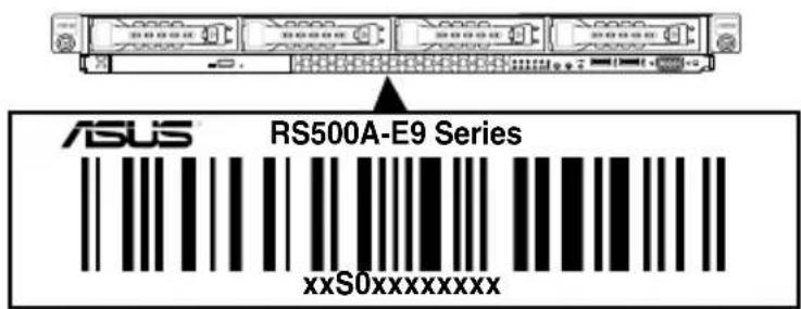
1.2 Serial number label
Before requesting support from the ASUS Technical Support team, you must take note of the product's serial number containing 12 characters such as xxS0xxxxxxxxx shown as the figure below. With the correct serial number of the product, ASUS Technical Support team members can then offer a quicker and satisfying solution to your problems.
text_image
ASUS RS500A-E9 Series xxS0xxxxxxxxxx1.3 System specifications
The ASUS RS500A-E9 Series is a 1U barebone server system featuring the ASUS KNPA-U16 Server Board. The server supports AMD EPYCTM 7000 Series processors plus other latest technologies through the chipsets onboard.
| Model Name | RS500A-E9-PS4 RS500A-E9-RS4 RS500A-E9-RS4-U | ||
| Processor Support | 1 x Socket SP3 (LGA 4094)AMD EPYCTM 7000 Series Processor (up to 180W) | ||
| Memory | Total Slots | 16 (8-channel, 2-DIMM per Channel) | |
| Capacity | Maximum up to 2048GB | ||
| Memory Type | DDR4 2666/2400/2133 RDIMM/LR-DIMM/LR-DIMM 3DS | ||
| Memory Size | 32GB, 16GB, 8GB, 4GB (RDIMM)64GB, 32GB (LRDIMM)128GB, 64GB (LRDIMM 3DS)* Refer to www.asus.com for the latest memory AVL update. | ||
| Expansion Slots | Total PCI/PCI-X/PCI-ESlots | 2+1 | |
| Slot Type | 1 x PCIe 3.0 x16 (x16 link); FH,HL1 x PCIe 3.0 x8 (x8 link); FH,HL1 x OCP 2.0 Mezzanine (x8 link) | ||
| Disk Controller | SATAController | CPU Integrated | |
| SAS Controller | Optional kits:- ASUS PIKE II 3008 8-port SAS HBA Card- ASUS PIKE II 3108 8-port SAS HW RAID CardSupport SAS 12Gbps | ||
| NVMeController | N/A CPU Integrated | ||
| Storage Bays | I = internalA or S = hot-swappable | 4 x 3.5" or 2.5" Hot-swap Storage Bays(SATA/SAS Supported) | 4 x 3.5" or 2.5" Hot-swap Storage Bays(SATA/SAS/NVMe Supported) |
| Networking | LAN | 1 x Dual Port Intel I350-AM2 Gigabit LAN controller1 x Management Port | |
| Infiniband | Optional Kit:Mellanox MCX453A-FCAT Card | ||
| Graphic | VGA | Aspeed AST2500 64MB | |
(continued on the next page)
| Model Name | RS500A-E9-PS4 R500A-E9-RS4 R500A-E9-RS4-U | |||
| Auxiliary Storage Device Bay (Optical Drive) | 1 x Slim-type Optical Drive | |||
| Front I/O Ports | 2 x USB 3.0 ports1 x VGA port | |||
| Rear I/O Ports | 2 x USB 3.0 ports1 x VGA port2 x RJ-45 1GbE LAN ports1 x RJ-45 Management port | |||
| Switch/LED | Rear:- 1 x Power Switch/LED- 1 x Q-Code/Port 80 LEDFront:- 1 x Power Switch/LED- 1 x Location Switch/LED- 1 x Reset Switch- 1 x Message LED- 4 x LAN LED (LED1~2 for on-board LAN, 3~4 for OCP LAN) | |||
| OS Support | Windows® Server 2016RedHat® Enterprise LinuxSuSE® Linux Enterprise ServerCentOSUbuntuVMwareCitrix XenServer* Please find the latest OS support from http://www.asus.com/ | |||
| Management Solution | Software | ASUS Control Center | ||
| Out of Band Remote Management | On-Board ASMB9-iKVM for KVM-over-IP | |||
| Regulatory Compliance | BSMI, CE, FCC | |||
| Dimension (HH x WW x DD) | 615 x 444 x 44mm (1U)24.21" x 17.48" x 1.73" | |||
| Net Weight Kg (CPU, DRAM & HDD not included) | 10 Kg 11 Kg 11.5 Kg | |||
| Gross Weight Kg (CPU, DRAM & HDD not included, Packing included) | 16 Kg 17 Kg 17.5 Kg | |||
(continued on the next page)
| Model Name | RS500A-E9-PS4 RS500A-E9-RS4 RS500A-E9-RS4-U | |
| Power Supply(following different configuration by region) | Single 650W 80 PLUS Platinum Power Supply Rating:100~127/200~240Vac,9A/5A, 50~60Hz, Class I | 1+1 Redundant 770W 80 PLUS Platinum Power SupplyRating: 100~127/200~240 Vac, 10A/5A,50~60Hz, Class I |
| Environment | Operating temperature: 10°C – 35°CNon operating temperature: -40°C – 70°CNon operating humidity: 20% – 90% (Non condensing) | |
*Specifications are subject to change without notice.
1.4 Front panel features
The barebone server displays a simple yet stylish front panel with easily accessible features. The power and reset buttons, LED indicators, slim type optical drive, and two USB ports are located on the front panel.

Refer to the Front panel LEDs section for the LED descriptions.

text_image
Rack screw Rack screw HDD 1 HDD 2 HDD 3 HDD 4 Optical drive (optional) Asset tag (hidden) LAN 4 LED LAN 3 LED LAN 2 LED LAN 1 LED Message LED HDD LED VGA port USB 3.0 ports Reset button Location switch Power button1.5 Rear panel features
The rear panel includes the expansion slots, system power socket, and rear fans. The middle part includes the I/O shield with openings for the rear panel connectors on the motherboard.
RS500A-E9-RS4 / RS500A-E9-RS4-U

text_image
Power cord connector and Redundant power supply LAN port for iKVM* USB 3.0 ports Gigabit LAN port 1 (bottom) and 2 (top) VGA port Q-Code LED PCI-E slot Locate LED Message LED OCP 2.0 Mezzanine slot Power buttonRS500A-E9-PS4

text_image
Power cord connector and power supply LAN port for iKVM* USB 3.0 ports Gigabit LAN port 1 (bottom) and 2 (top) VGA port Q-Code LED PCI-E slot Locate LED Message LED OCP 2.0 Mezzanine slot Power button
*This port is for ASUS ASMB9-iKVM controller card only.
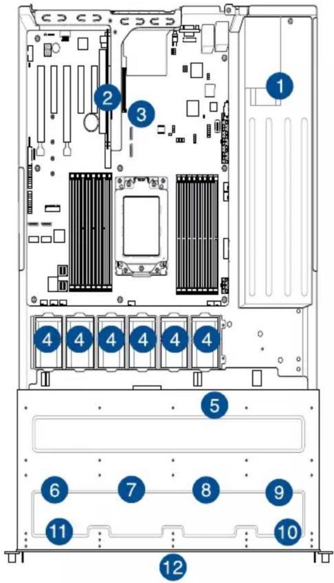
1.6 Internal features
The barebone server includes the basic components as shown.
text_image
Diagram of a server rack with numbered components, likely an industrial or computing device layout.- Power supply and power fan
- PCI Express slot Riser Card
- ASUS KNPA-U16 Server Board
- System fans
- SAS / SATA backplane (hidden)
- HDD tray 1 - Connects to backplane
- HDD tray 2 - Connects to backplane
- HDD tray 3 - Connects to backplane
- HDD tray 4 - Connects to backplane
- Front I/O boards (hidden)
- Slim-type optical drive
- Asset Tag

Turn off the system power and detach the power supply before removing or replacing any system component.

The barebone server does not include a floppy disk drive. Connect a USB floppy disk drive to any of the USB ports on the front or rear panel if you need to use a floppy disk.
WARNING
HAZARDOUS MOVING PARTS
KEEP FINGERS AND OTHER BODY PARTS AWAY
1.7 LED information
1.7.1 Front panel LEDs

text_image
LAN 4 LED LAN 3 LED LAN 2 LED LAN 1 LED Location switch Power button HDD LED Message LED| LED Icon Display status Description | |||
| Power LED | ON System power ON | ||
| HDD Access LED | OFFBlinking | No activityRead/write data into the HDD | |
| Message LED | OFFON | System is normal; no incoming eventA hardware monitor event is indicated | |
| Location LED | OFFON | Normal statusLocation switch is pressed(Press the location switch again to turn off) | |
| LAN LEDs | OFFBlinkingON | No LAN connectionLAN is transmitting or receiving dataLAN connection is present | |
1.7.2 LAN (RJ-45) LEDs
LAN port LED indications
| Activity/Link LED Speed LED | ||
| Status Description Status Description | ||
| OFF No link | GREEN 1 Gbps connectionGREEN Linl | |
| BLINKING Data activity | ||
Dedicated Management LAN port (DM_LAN1) LED indications
| Activity/Link LED Speed LED | |||
| Status Description | Status | Description | |
| OFF No link OFF | 10 Mbps connection |  | |
| YELLOW | Linked | ORANGE | 100 Mbps connection |
| BLINKING Data activity | GREEN 1 Gbps connection | ||
1.7.3 HDD status LED
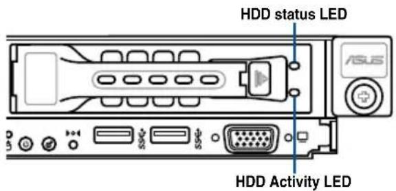
text_image
HDD status LED ASUS HDD Activity LED| SATA/SAS HDD LED Description | |||
| HDD Status LED | GREEN ON | SATA/SAS HDD power ON | |
| RED ON | HDD has failed and should be swapped immediately | ||
| GREEN/RED | Blinking RAID rebuilding | ||
| GREEN/RED | OFF HDD not found | ||
| HDD Activity LED | GREEN Blinking Read/write data from/into the SATA/SAS HDD | ||
Hardware Information
2
This chapter lists the hardware setup procedures that you have to perform when installing or removing system components.
2.1 Chassis cover
Removing the rear cover
- Locate and remove the front side screws.

text_image
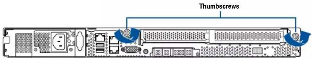
Front side screw- Loosen the two thumbscrews on the rear panel to release the rear cover from the chassis.
text_image
Thumbscrews- Firmly hold the cover and slide it toward the rear panel for about half an inch until it is disengaged from the chassis.
- Lift the cover from the chassis.
- To reattach the rear cover, reverse step 1 to 4.

A protection film is pre-attached to the system cover before shipping. Please remove the protection film before turning on the system for proper heat dissipation.

text_image
Diagram showing a road intersection with directional arrows and labeled points, likely indicating movement or navigation.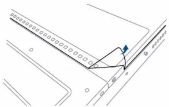
natural_image
Pure architectural line drawing of a road with a triangular structure and directional arrow (no text or symbols)2.2 Central Processing Unit (CPU)
The motherboard comes with a surface mount Socket SP3 designed for the AMD EPYCTM 7000 Series.

- Upon purchase of the motherboard, ensure that the PnP cap is on the socket and the socket contacts are not bent. Contact your retailer immediately if the PnP cap is missing, or if you see any damage to the PnP cap/socket contacts/motherboard components. ASUS will shoulder the cost of repair only if the damage is shipment/transit-related.
- Keep the cap after installing the motherboard. ASUS will process Return Merchandise Authorization (RMA) requests only if the motherboard comes with the cap on the Socket SP3.
- The product warranty does not cover damage to the socket contacts resulting from incorrect CPU installation/removal, or misplacement/loss/incorrect removal of the PnP cap.
2.2.1 Installing the CPU and heatsink
To install the CPU and heatsink:
-
Remove the rear cover. For more information, see the section Chassis cover.
-
Locate the CPU socket on your motherboard..
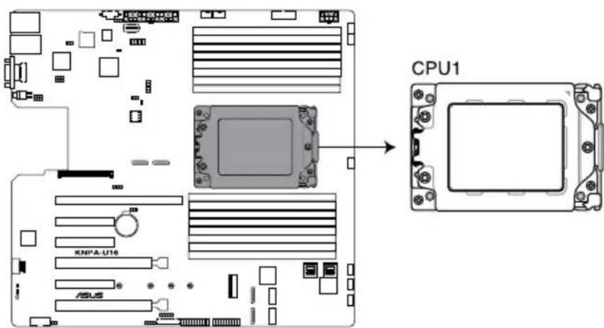
text_image
CPU1 KNPA-U16 ASUSKNPA-U16 CPU SP3 Socket
- Loosen each screw one by one in the sequence shown on the socket to open the load plate.
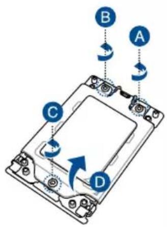
text_image
A B C D- Slightly lift open the rail frame.
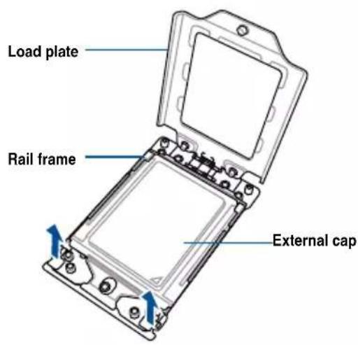
text_image
Load plate Rail frame External cap- Slide the external cap out of the rail frame.

text_image
External cap Rail frame PnP cap- Slide the carrier frame with CPU into the rail frame, then remove the PnP cap.

The carrier frame with CPU fits in only one correct orientation. DO NOT force the carrier frame with CPU into the rail frame.
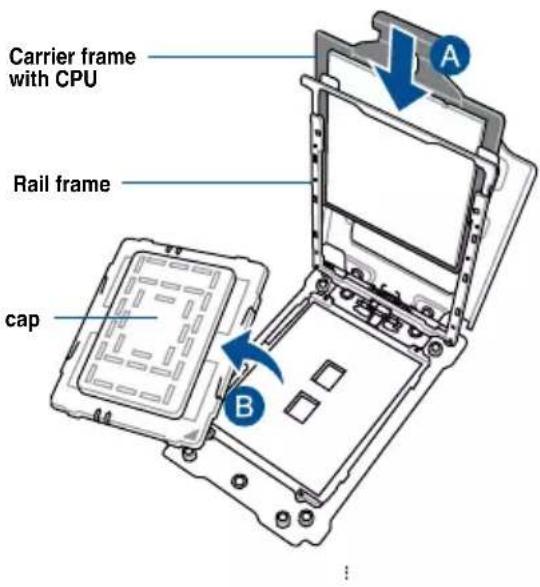
text_image
Carrier frame with CPU Rail frame cap A B- Gently push the rail frame just enough to let it sit on top of the CPU socket.
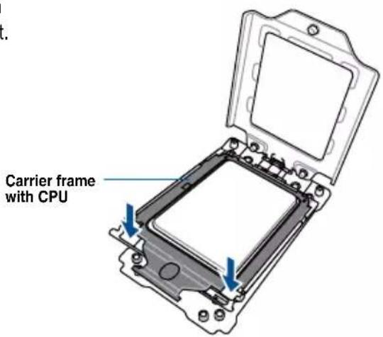
text_image
Carrier frame with CPU- Close the load plate just enough to let it sit on top of the CPU, then secure each screw one by one in the sequence shown on the socket to completely secure the load plate.

The load plate screws are T20 models. A torque value of 12 inch-lbf is recommended.

text_image
A B C- Twist each of the four screws with a screwdriver just enough to attach the heatsink to the motherboard. When the four screws are attached, tighten them one by one in a diagonal sequence to complete the installation.

The heatsink screws are T20 models. A torque value of 12 inch-lbf is recommended.
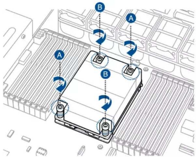
text_image
Diagram of an electronic device with labeled components A and B, showing battery layout and rotation arrows.2.3 System memory
2.3.1 Overview
The motherboard comes with sixteen (16) Double Data Rate 4 (DDR4) Dual Inline Memory Modules (DIMM) sockets.
The figure illustrates the location of the DDR4 DIMM sockets:

text_image
DIMM_H2 DIMM_H1 DIMM_G2 DIMM_G1 DIMM_F2 DIMM_F1 DIMM_E2 DIMM_E1 DIMM_A1 DIMM_A2 DIMM_B1 DIMM_B2 DIMM_C1 DIMM_C2 DIMM_D1 DIMM_D2KNPA-U16 288-pin DDR4 DIMM sockets
2.3.2 Memory Configurations
You may install 32GB, 16GB, 8GB, 4GB RDIMM, 64GB, 32GB LRDIMM, or 128GB, 64GB LRDIMM 3DS into the DIMM sockets using the memory configurations in this section.
| Memory configurations | |||||||||||||||||||
| DIMM | |||||||||||||||||||
| A1 | A2 | B1 | B2 | C1 | C2 | D1 | D2 | E1 | E2 | F1 | F2 | G1 | G2 | H1 | H2 | ||||
| 1 DIMM | √ | ||||||||||||||||||
| 2 DIMMs | √ | √ | |||||||||||||||||
| 4 DIMMs | √ | √ | √ | √ | |||||||||||||||
| 6 DIMMs | √ | √ | √ | √ | √ | √ | |||||||||||||
| 8 DIMMs | √ | √ | √ | √ | √ | √ | √ | √ | |||||||||||
| 10 DIMMs | √ | √ | √ | √ | √ | √ | √ | √ | √ | √ | |||||||||
| 12 DIMMs | √ | √ | √ | √ | √ | √ | √ | √ | √ | √ | √ | ||||||||
| 14 DIMMs | √ | √ | √ | √ | √ | √ | √ | √ | √ | √ | √ | √ | √ | ||||||
| 16 DIMMs | √ | √ | √ | √ | √ | √ | √ | √ | √ | √ | √ | √ | √ | √ | √ | ||||

- Always install DIMMs with the same CAS latency. For optimum compatibility, it is recommended that you obtain memory modules from the same vendor.
- Start installing the DIMMs in slots A2.
2.3.3 Installing a DIMM on a single clip DIMM socket

Ensure to unplug the power supply before adding or removing DIMMs or other system components. Failure to do so may cause severe damage to both the motherboard and the components.
- Unlock a DIMM socket by pressing the retaining clip outward.
- Align a DIMM on the socket such that the notch on the DIMM matches the DIMM slot key on the socket.

text_image
DIMM notch DIMM slot key Unlocked retaining clip
A DIMM is keyed with a notch so that it fits in only one direction. DO NOT force a DIMM into a socket in the wrong direction to avoid damaging the DIMM.
- Hold the DIMM by both of its ends then insert the DIMM vertically into the socket. Apply force to both ends of the DIMM simultaneously until the retaining clip snaps back into place and the DIMM cannot be pushed in any further to ensure proper sitting of the DIMM.
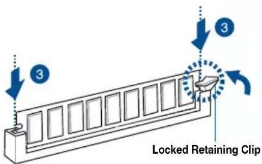
text_image
3 3 Locked Retaining Clip
Always insert the DIMM into the socket vertically to prevent DIMM notch damage.
Removing a DIMM from a single clip DIMM socket
- Press the retaining clip outward to unlock the DIMM.
- Remove the DIMM from the socket.
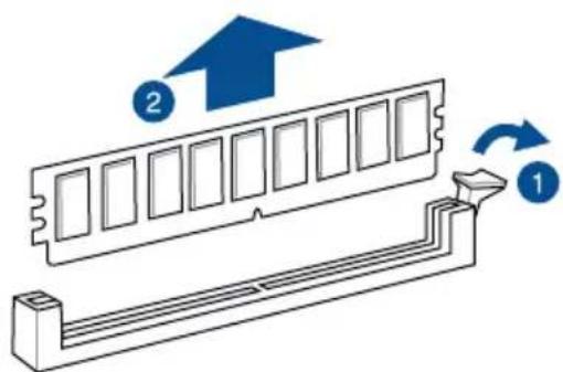
text_image
Diagram showing a computer RAM module with labeled components and directional arrows indicating motion or assembly.
Support the DIMM lightly with your fingers when pressing the retaining clips. The DIMM might get damaged when it flips out with extra force.
2.4 Hard disk drives
The system supports four hot-swap SATA/SAS hard disk drives. The hard disk drive installed on the drive tray connects to the motherboard SATA/SAS ports via the SATA/SAS backplane.
To install a 3.5" hot-swap SATA/SAS HDD:
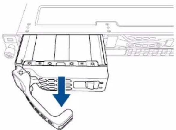
- Push the spring lock to the right (A) then pull the tray lever outward (B) to release the drive tray. The drive tray ejects slightly after you pull out the lever.

text_image
tray lever B A spring lock- Firmly hold the tray lever and pull the drive tray out of the bay.
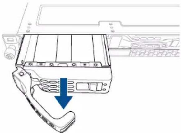
natural_image
Technical line drawing of a mechanical component with a blue arrow indicating a downward motion (no text or symbols present)-
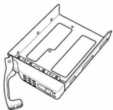
Place the drive tray on a flat and stable surface.
-
Prepare the SATA/SAS HDD and the bundled set of screws.
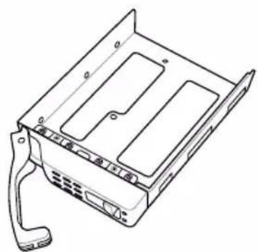
natural_image
Line drawing of a computer drive chassis with mounting bracket and handle (no text or symbols)- Place the 3.5" SATA/SAS HDD into the tray then secure it with four screws.
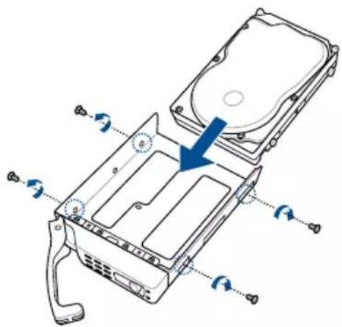
natural_image
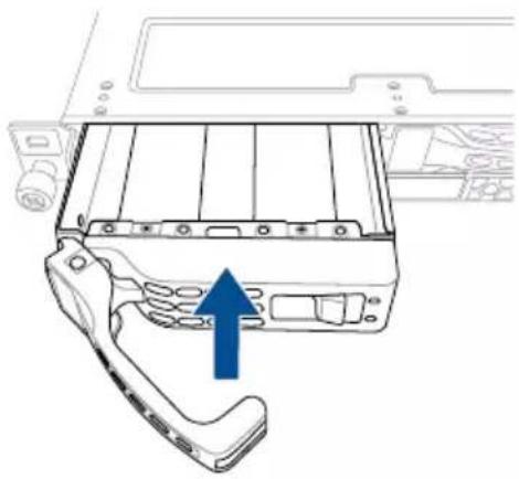
Diagram of a hard disk drive assembly with arrows indicating rotation and mounting points (no text or labels)- Insert the drive tray and HDD assembly all the way into the depth of the bay until just a small fraction of the tray edge protrudes.
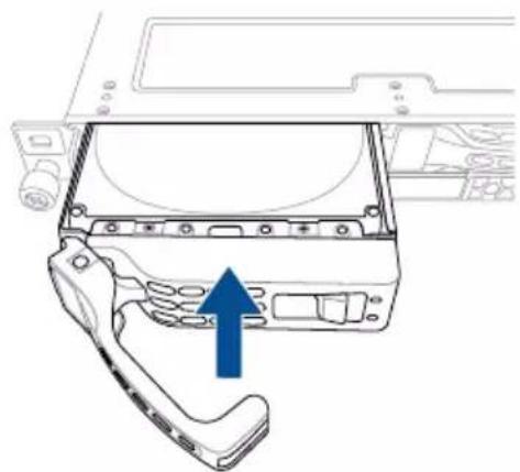
natural_image
Technical line drawing of a mechanical component with an arrow indicating upward motion (no text or symbols present)
When installed, the SATA/SAS connector on the drive connects to the SATA/SAS interface on the backplane.
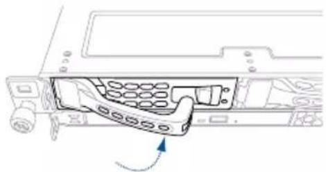
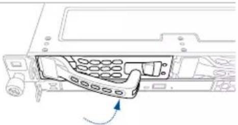
- Push the tray lever until it clicks and secures the drive tray in place.

The drive tray is correctly placed when its front edge aligns with the bay edge.
- Repeat steps 1 to 7 to install the other SATA/SAS HDDs.
natural_image
Diagram of a computer interface showing a keypad inserted into a drive, with no visible text or symbols.To install a 2.5" storage device to the front panel:
- Push the spring lock to the right (A) then pull the tray lever outward (B) to release the drive tray. The drive tray ejects slightly after you pull out the lever.

text_image
tray lever B A spring lock- Firmly hold the tray lever and pull the tray out of the bay.
natural_image
Technical line drawing of a mechanical component with a blue arrow indicating a downward motion (no text or symbols present)-
Place the tray on a flat and stable surface.
-
Prepare the 2.5" storage device and the bundled set of screws.
natural_image
Line drawing of a computer drive chassis showing internal compartments and casing (no text or symbols)- Place the 2.5" storage device into the tray then secure it with four screws.

natural_image
Diagram of a computer case with a downward arrow indicating compression or disassembly (no text or symbols present)- Insert the tray and storage device assembly all the way into the depth of the bay until just a small fraction of the tray edge protrudes.
natural_image
Technical line drawing of a mechanical device with an arrow indicating a component (no text or symbols present)
When installed, the SATA/NVMe connector on the storage device connects to the SATA/NVMe interface on the backplane.
- Push the tray lever until it clicks and secures the tray in place.
natural_image
Diagram of a computer interface showing a keypad inserted into a drive bay, with no visible text or symbols.
The tray is correctly placed when its front edge aligns with the bay edge.
- Repeat steps 1 to 7 to install the other storage devices.
2.5 Expansion slot
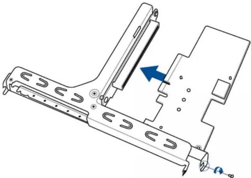
2.5.1 Installing an expansion card to the riser card bracket
The barebone server comes with a riser card bracket. You need to remove the bracket if you want to install PCI Express x8 or x16 expansion cards.
To install a PCI Express x8 or x16 card:
- Firmly hold the riser card bracket, then pull it up to detach it from the PCI Express x24 slot on the motherboard.
- Place the riser card bracket on a flat and stable surface, then remove the screw from the slot bay.
- Install a PCI Express x8 or x16 card to the bracket as shown.
- Secure the card with a screw.
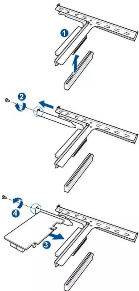
text_image
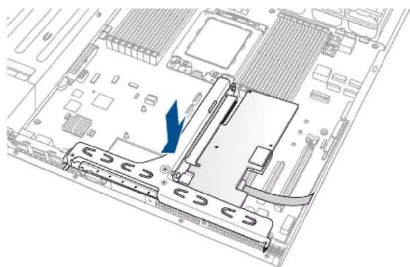
Technical diagram illustrating four steps of a mechanical assembly with labeled components and directional arrows indicating motion.- Install the riser card bracket and PCI Express card assembly back into the PCI Express x24 slot on the motherboard. Ensure that the golden connectors of the riser card bracket is firmly seated in place.

natural_image
Mechanical assembly diagram showing a bracket with a labeled component (no text or symbols present)2.5.2 Installing an ASUS PIKE II card
You can install an ASUS PIKE II card on the provided PCI-E slot onboard.
To install an ASUS PIKE II card:
- Firmly hold the riser card bracket, then pull it up to detach it from the PCI Express x24 slot on the motherboard.

natural_image
Diagram of a computer motherboard showing a CPU socket and drive mechanism (no text or labels)- Remove the screw that secures the metal cover to the riser card bracket, then remove the metal cover.
natural_image
Technical line drawing of a mechanical clamp or bracket assembly with a blue directional arrow indicating motion (no text or symbols present)- Prepare your ASUS PIKE II card.
- Insert the expansion card into the PCI-E slot. Ensure that the golden fingers are totally inserted into the slot, then secure the ASUS PIKE II card with the screw removed before.
natural_image
Technical diagram of a mechanical assembly with a blue arrow indicating a component (no text or symbols present)- Remove the default mini-SAS HD cable from the motherboard.

natural_image
Interior view of a computer tower drive bay showing internal components like CPU, RAM slots, and a highlighted disk (no text or labels)- Connect the mini-SAS HD cable to connector 1 of the ASUS PIKE II card.

text_image
Connect to PIKE II connector 1- Reinstall the riser card bracket into the PCI Express x24 slot on the motherboard. Ensure that the golden connectors of the riser card bracket is firmly seated in place.
natural_image
Diagram of a computer motherboard showing CPU socket and drive mechanism (no text or labels)2.5.3 Installing M.2 (NGFF) cards
To install an M.2 (NGFF) card:
- Locate the M.2 (NGFF) connector on your motherboard.

text_image
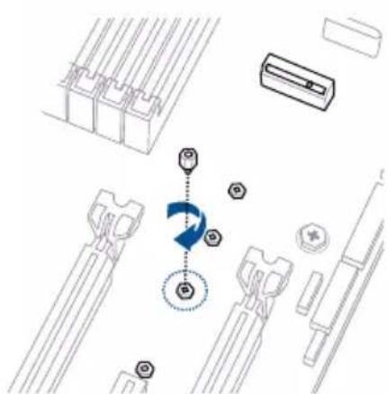
KNPA-U16 NGFF connector NGFF1- Remove the top screw and the stand from the motherboard.
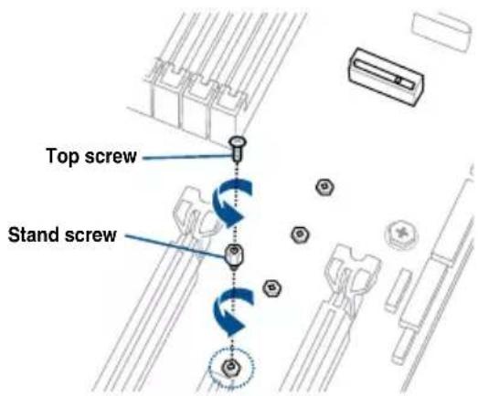
text_image
Top screw Stand screw- Select an appropriate screw hole on the motherboard for your M.2 card, then secure the stand to the motherboard.
natural_image
Pure mechanical assembly diagram without any text, numbers, or symbols-
Prepare the M.2 card.
-
Align and insert the M.2 card into the M.2 connector on the motherboard.
Ensure that the golden connector of the M.2 card is inserted firmly in place and that the screw hole on the M.2 card matches the stand screw on the motherboard.
- Secure the M.2 card with the top screw.

Ensure that the M.2 card is positioned between the top screw and the stand screw before securing it.

natural_image
Technical diagram of a mechanical assembly with no visible text or symbols2.5.4 Installing Mezzanine cards
To install a Mezzanine card:
- Locate the Mezzanine card connector on your motherboard.

text_image
KNPA-U16 MEZZPCIE connector MEZZPCIE1- Firmly hold the riser card bracket, then pull it up to detach it from the PCI Express x24 slot on the motherboard.

natural_image
Diagram of a computer motherboard showing a CPU socket and drive mechanism (no text or labels)- Select the slots that are going to be used for your Mezzanine card, then use a screwdriver and pry the corresponding slots until it pops off.
natural_image
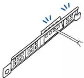
Illustration of a mechanical component with a lever and fasteners, no text or symbols present- Prepare your Mezzanine card and the signal cable. Connect the signal transmission end (white) to the AUXLED_CON header on the card.
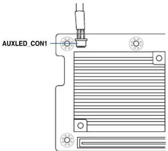
text_image
AUXLED_CON1- Insert the ports of the Mezzanine card into the mounting hole on the chassis, then insert the golden connector of the Mezzanine card into the MEZZPCIE1 (OCP) connector on the motherboard.
Ensure that the stand screws on the motherboard is aligned and matched to the screw holes of the Mezzanine card.
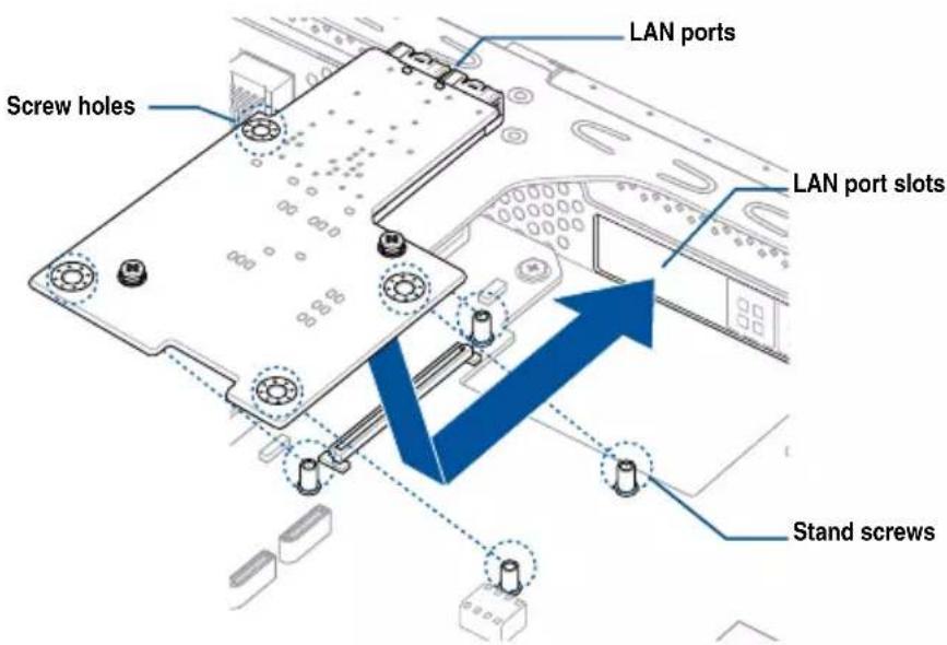
text_image
Screw holes LAN ports LAN port slots Stand screws- Secure the Mezzanine card with the four (4) bundled screws.

text_image
Technical diagram showing a device chassis with labeled components and directional arrows indicating motion or movement.- Connect the signal end (black) to the OCP_LED1 header on the motherboard.

text_image
KNPA-U16 OCP_LED1 connector OCP_LED1 LAN3LINK# LAN4LINK# NC PIN 1
The two ends of the signal cable are different in size and color for easy recognition. Please refer to your exact cable.
- Reinstall the riser card bracket into the PCI Express x24 slot on the motherboard. Ensure that the golden connectors of the riser card bracket is firmly seated in place.
2.5.5 Configuring an expansion card
After installing the expansion card, configure the it by adjusting the software settings.
- Turn on the system and change the necessary BIOS settings, if any. See Chapter 5 for information on BIOS setup.
- Assign an IRQ to the card. Refer to the following tables.
- Install the software drivers for the expansion card.
Standard Interrupt assignments
| IRQ Priority Standard function | |
| 0 1 System Timer | |
| 1 2 Keyboard Controller | |
| 2 - Programmable Interrupt | |
| 3* 11 Communications Port (COM2) | |
| 4* 12 Communications Port (COM1) | |
| 5* 13 -- | |
| 6 14 Floppy Disk Controller | |
| 7* 15 -- | |
| 8 3 System CMOS/Real Time Clock | |
| 9* 4 ACPI Mode when used | |
| 10* 5 IRQ Holder for PCI Steering | |
| 11* 6 IRQ Holder for PCI Steering | |
| 12* 7 PS/2 Compatible Mouse Port | |
| 13 8 Numeric Data Processor | |
| 14* 9 Primary IDE Channel | |
| 15* 10 Secondary IDE Channel | |
* These IRQs are usually available for ISA or PCI devices.
2.6 Cable connections

- The bundled system cables are pre-connected before shipment. You do not need to disconnect these cables unless you will remove pre-installed components to install additional devices.
• Refer to Chapter 4 for detailed information on the connectors.

text_image
DM LAN1_USB3 12 LAN12 VGA 16H1 VGA_SW1 VGA_SW1 LAN50 LAN_SW2 LAN_SW1 ASPEED AS125GD VIP2.2C1 SBU_P_SEL1 SBPWT1 MEZZF0E1 MPCIE_HD1 MPCIE_HD2 DDR1 LED1 PCI6 PCI5 PCI4 PCI3 PCI2 PCI1 PORT8U LEDs NESLED NESLED OSI-LED1 OSI-LED1 LAN34_LED1 LAN34-LCD1 LAN34-LCD2 CPU1 DDR4 DIMM_A1 (64bit, 288-pin module) DDR4 DIMM_A2 (64bit, 288-pin module) DDR4 DIMM_B1 (64bit, 288-pin module) DDR4 DIMM_B2 (64bit, 288-pin module) DDR4 DIMM_C1 (64bit, 288-pin module) DDR4 DIMM_C2 (64bit, 288-pin module) DDR4 DIMM_D1 (64bit, 288-pin module) DDR4 DIMM_D2 (64bit, 288-pin module) DATA-A2 DATA-B2A A2 DATA-D2A B2A B2A B2A B2A B2A B2A B2A B2A B2A B2A B2A B2A B2A B2A B2A B2A B2A B2A B2A B2A B2A B2A B2A B2A B2A B2A B2A B2A B2A B2A B2A B2A B2A B PRINT_FAN1 PRINT_FAN2 PRINT_FAN3 CPU_FANFRNT_FAN3 PRINT_FAN5 PRINT_FAN6 PRINT_FAN7 PRINT_FAN8 PRINT_FAN9 PRINT_FAN10 CPU_FANFRNT_FAN0Standard cables connected to the motherboard
- 24-pin ATX power connector (from power supply to motherboard)
- 8-pin 12V power connector (from power supply to motherboard)
- System fan connector (from system fan to motherboard)
- USB connector (from motherboard to front I/O board)
- SATA connector (system default; from motherboard to backplane)
- System auxiliary panel connector (from motherboard to front I/O board)
- System panel connector (from motherboard to front I/O board)
- Mini-SAS HD connector (from motherboard to backplane)
2.7 SATA/SAS backplane cabling
natural_image
Diagram of a computer motherboard showing CPU socket, drive bays, and memory slots (no text or labels)RS500A-E9-RS4 / RS500A-E9-PS4
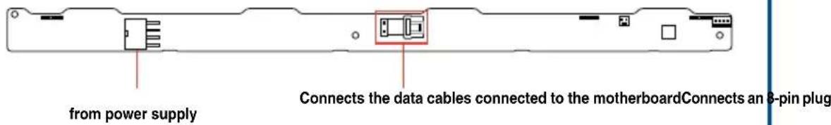
text_image
from power supply Connects the data cables connected to the motherboardConnects an 8-pin plug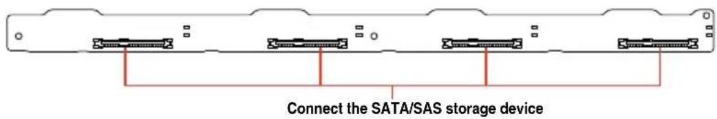
text_image
Connect the SATA/SAS storage deviceRS500A-E9-RS4-U
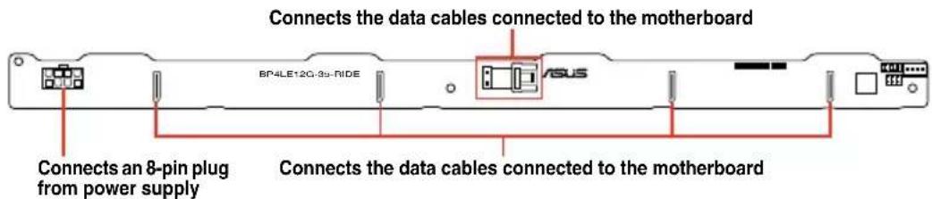
text_image
Connects the data cables connected to the motherboard BP4LE12G-3u-RIDE Connects an 8-pin plug from power supply Connects the data cables connected to the motherboard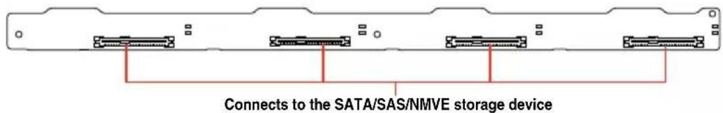
text_image
Connects to the SATA/SAS/NMVE storage device2.8 Removable/optional components
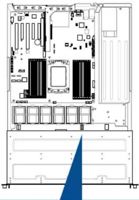
You may need to remove previously installed system components when installing or removing system devices. Or you may need to install the optional components into the system. This section tells how to remove/install the system fans:

Ensure that the system is turned off before removing any components from your system.
2.8.1 System fans
To uninstall the system fans:
- Disconnect the system fan cable from the fan connector on the motherboard.
- Lift the fan, then set aside.
- Repeat steps 1 to 2 to uninstall the other system fans.
To reinstall the system fans
- Insert the fan to the fan cage. The airflow directional arrow on the fan side should point towards the system rear panel.
- Connect the system fan cable to the fan connector on the motherboard.
Installation Options
This chapter describes how to install the optional components and devices into the barebone server.
3
3.1 Rail kit installation
3.1.1 Tool-less Friction Rail Kit
The tool less design of the rail kit allows you to easily install the rack rails into the server rack without the need for additional tools. The kit also comes with a metal stopping bracket that can be installed to provide additional support and stability to the server.
The tool-less rail kit package includes:
Fixing latches
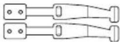
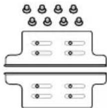
Rail components (screws included)
natural_image
Pure diagram of two mechanical components with evenly spaced holes, no text or symbols presentSet of screws

text_image
Latch screws Rail Washers Rail screwsTool-less rack rail
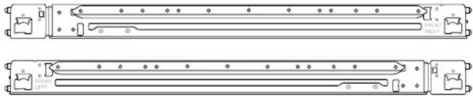
natural_image
Technical line drawing of two mechanical components with mounting holes and mounting brackets (no text or symbols)3.1.2 Installing the tool-less rack rail
To install the tool-less rack rails into the rack:
- Secure the two fixing latches to the two sides of the server using the set of latch screws.

The locations of the screw holes vary with different server models. Refer to your server user manual for details.

text_image
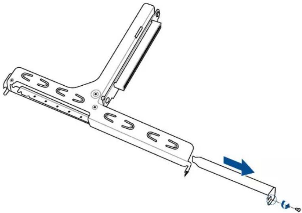
Front end of system- Slightly slide out and extend the right rack rail, then prepare one of the bundled rail components.
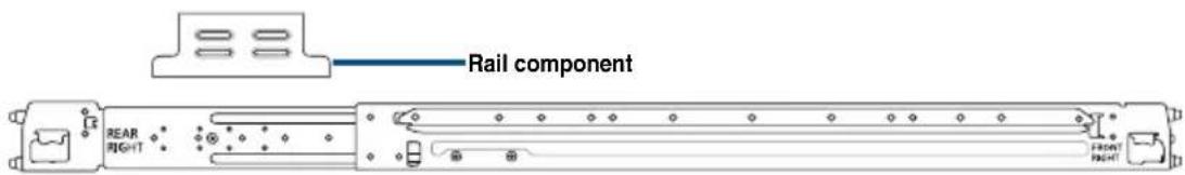
text_image
Rail component REAR GHT- Align the rail component with the right rack rail and secure it using four (4) bundled screws.
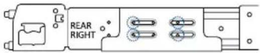
text_image
REAR RIGHT-
Follow steps 2 and 3 to secure the rail component to the left rail rack.
-
Select a desired space and place the appropriate rack rail (left and right) on opposite positions on the rack.

A 1U space consists of three square mounting holes with two thin lips on the top and the bottom.
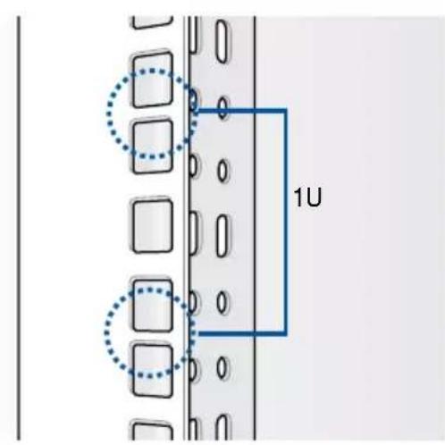
text_image
1U- Secure the rail components to the rail using the bundled screws.
7 Press the spring lock ( A ) then insert the studs into the selected square mounting holes on the rack post.
-
Press the spring lock on the other end of rail then insert the stud into the mounting hole on the rack post. Extend the rack rail, if necessary.
-
(Optional) Use the rail screw and rail washer ( B ) that comes with the kit to secure the rack rail to the rack post.
-
Perform steps 3 to 5 for the other rack rail.

Ensure that the installed rack rails (left and right) are aligned, secured, and stable in place.

text_image
B A- Lift the server chassis and insert into the rack rail.

Ensure that the rack rail cabinet and the rack posts are stable and standing firmly on a level surface.
3.2 Rail kit dimensions

text_image
43.6mm 900mm 43.6mm 589mmMotherboard Information
4
This chapter includes the motherboard layout and brief descriptions of the jumpers and internal connectors.
4.1 Motherboard layout

text_image
Technical diagram of a CPU-based electronic system with labeled components and modules, including CPU1, GPU, and hardware interfaces.Layout contents
| Internal connectors / Sockets / Jumpers / LEDs Page | |
| 1. LAN controller settings (3-pin LAN_SW1-2) 4-5 | |
| 2. LANNCSI setting (3-pin LANNCSI_SEL1) 4-7 | |
| 3. Micro SD card slot (MSD1) 4-20 | |
| 4. Smart Ride Through (SmaRT) setting (3-pin SMART_PSU1) 4-7 | |
| 5. Power Supply SMBus connector (5-pin PSUSMB1) 4-11 | |
| 6. ATX power connectors (24-pin EATXPWR1, 8-pin EATX12V1) 4-14 | |
| 7. CPU, front, and rear fan connectors (4-pin FRNT_FAN1-7, REAR_FAN1-2) | 4-13 |
| 8. USB 3.0 connector (20-1 pin USB3_34; 4-pin Type-A USB3_4) 4-12 | |
| 9. DDR4 DIMM sockets 2-7 | |
| 10. CPU socket 2-3 | |
| 11. Serial ATA connectors (7-pin SATA1-4) 4-11 | |
| 12. Mini-SAS HD connectors (ISATA1-2) 4-21 | |
| 13. OCUPCIE connectors (MPCIE_HD1-6) | 4-18 |
| 14. M.2 (NGFF) connectors (NGFF1) 4-19 | |
| 15. System panel connector (20-1 pin PANEL1) 4-15 | |
| 16. Auxiliary panel connector (20-2 pin AUX_PANEL1, 20-pin AUX_PANEL2) | 4-16 |
| 17. Hard disk activity LED connector (4-pin HDLED1) 4-17 | |
| 18. LAN Activity LED connector (5-1 pin LAN34_LED1) | 4-13 |
| 19. Chassis Intrusion connectors (2-pin INTRUSION) | 4-18 |
| 20. Serial port connector (10-1 pin COM1) | 4-12 |
| 21. Clear RTC RAM (3-pin CLRTC1) | 4-4 |
| 22. Mezzanine PCIE card connectors (MEZZPCIE1) | 4-19 |
| 23. VGA controller setting (3-pin VGA_SW1) | 4-5 |
| 24. BMC Setting (3-pin BMC_EN1) | 4-6 |
| 25. VGA connector (10-1 pin VGA_HDR1) | 4-17 |
| 26. Trusted Platform Module connector (20-1 pin TPM1) | 4-14 |
| 27. VPP_I2C1 connector (10-1 pin VPP_I2C1) | 4-21 |
| 28. DMLAN setting (3-pin DM_IP_EN1) | 4-6 |
| 29. OCP LAN Activity LED connector (4-1 pin OCP_LED1) | 4-20 |
4.2 Jumpers
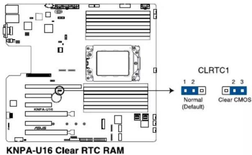
1. Clear RTC RAM (3-pin CLRTC1)
This jumper allows you to clear the Real Time Clock (RTC) RAM in CMOS. You can clear the CMOS memory of date, time, and system setup parameters by erasing the CMOS RTC RAM data. The onboard button cell battery powers the RAM data in CMOS which include system setup information such as system passwords.
To erase the RTC RAM:
- Turn OFF the computer and unplug the power cord.
- Move the jumper cap from the default pins 1–2 to pins 2–3. Keep the cap on pins 2–3 for about 5 to 10 seconds, then move the cap back to pins 1–2.
- Plug the power cord and turn ON the computer.
- Hold down the
key during the boot process and enter BIOS setup to re-enter data.

DO NOT remove the cap on CLRTC jumper default position except when clearing the RTC RAM. Removing the cap will cause system boot failure!

If the steps above do not help, remove the onboard battery and move the jumper again to clear the CMOS RTC RAM data. After the CMOS clearance, reinstall the battery.
text_image
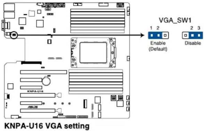
KNPA-U16 Clear RTC RAM CLRTC1 Normal (Default) 2 3 Clear CMOS2. VGA controller setting (3-pin VGA\_SW1)
This jumper allows you to enable or disable the onboard VGA controller. Set to pins 1–2 to activate the VGA feature.
text_image
VGA_SW1 1 2 Enable (Default) 2 3 Disable KNPA-U16 VGA setting3. LAN controller settings (3-pin LAN\_SW1-2)
These jumpers allow you to enable or disable the onboard LAN_SW1 or LAN_SW2. Set to pins 1-2 to activate the Gigabit LAN feature.

text_image
LAN_SW2 LAN_SW1 1 2 Enable (Default) 2 3 Disable KNPA-U16 LAN setting4. BMC Setting (3-pin BMC\_EN1)
This jumper allows you to enable or disable the Baseboard Management Controller (ASMB9).

text_image
KNPA-U16 BMC_EN1 setting BMC_EN1 1 2 Enable 2 3 Disable5. DMLAN setting (3-pin DM\_IP\_EN1)
This jumper allows you to select the DMLAN setting. Set to pins 2-3 to force the DMLAN IP to static mode (IP=10.10.10.10, submask=255.255.255.0).
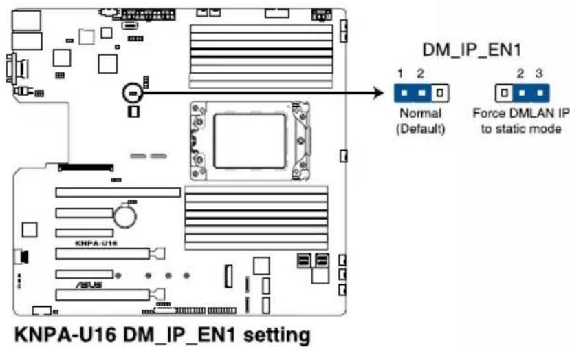
text_image
DN_IP_EN1 Normal (Default) Force DMLAN IP to static mode KNPA-U16 DM_IP_EN1 setting6. LANNCSI setting (3-pin LANNCSI\_SEL1)
This jumper allows you to select which LAN NCSI to function.

text_image
LANNCSI_SEL1 1 2 I350 for share LAN (Default) 2 3 OCP card for share LAN KNPA-U16 LANNCSI setting7. Smart Ride Through (SmaRT) setting (3-pin SMART\_PSU1)
This jumper allows you to enable or disable the Smart Ride Through (SmaRT) function. This feature is enabled by default. Set to pins 2-3 to disable it. When enabled, SmaRT allows uninterrupted operation of the system during an AC loss event.

text_image
SMART_PSU1 1 2 Enable (Default) 2 3 Disable KNPA-U16 Smart Ride Through setting4.3 Onboard LEDs
1. Standby Power LED (SBPWR1)
The motherboard comes with a standby power LED. The green LED lights up to indicate that the system is ON, in sleep mode, or in soft-off mode. This is a reminder that you should shut down the system and unplug the power cable before removing or plugging in any motherboard component. The illustration below shows the location of the onboard LED.
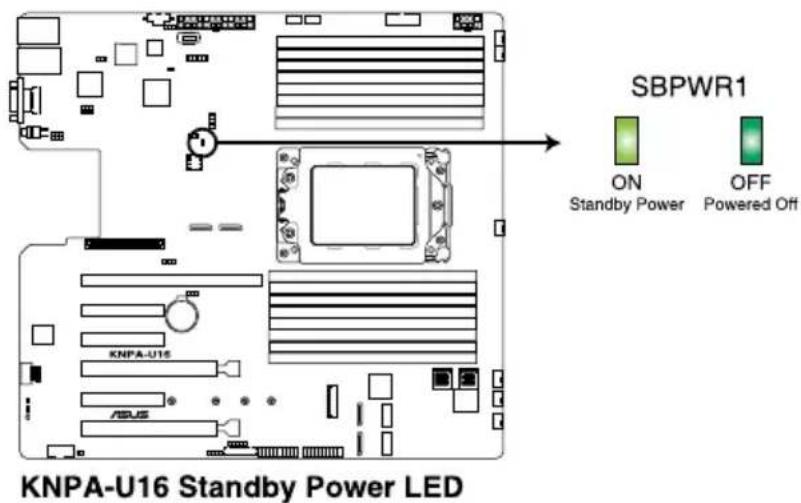
text_image
SBPWR1 ON Standby Power OFF Powered Off KNPA-U16 Standby Power LED2. BMC LED (BMCLED1)
The BMC LED lights up to indicate that the on-board BMC is functional.
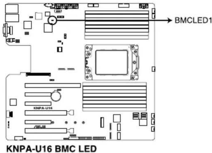
text_image
KNPA-U16 BMC LED BMCLED1 KNPA-U16
This LED functions only when you enable ASUS ASMB9.
3. Location LED (LOCLED1)
This onboard LED lights up when the Location button on the server is pressed or when triggered by a system management software. The Location LED helps visually locate and quickly identify the server in error on a server rack.
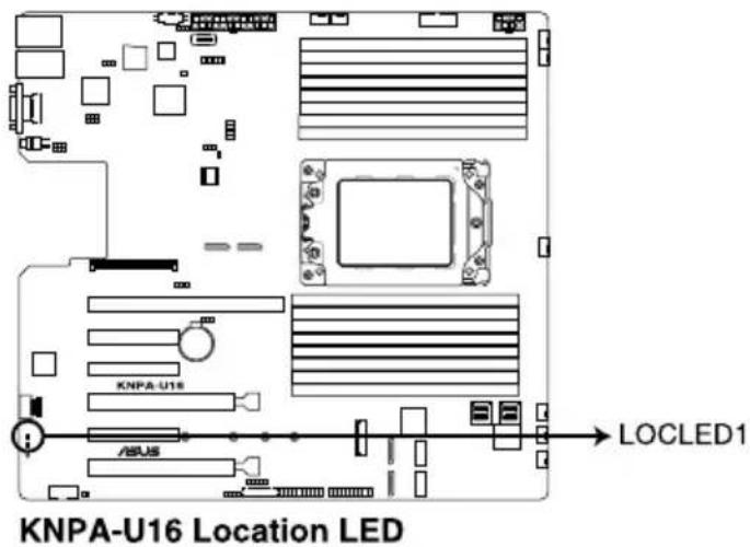
text_image
KNPA-U16 Location LED LOCLED14. Message LED (MESLED1)
This onboard LED lights up to red when there is a BMC event log is generated.
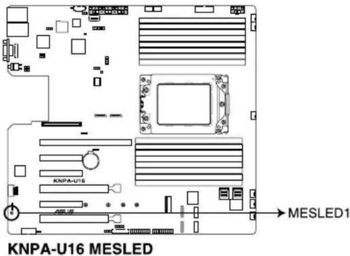
text_image
KNPA-U16 MESLED MESLED15. Hard disk activity LED (HDDLED1)
This LED is for the storage devices connected to the onboard SATA, or SATA/SAS add-on card. The read or write activities of any device connected to the onboard SATA, or SATA/SAS add-on card causes the rear panel LED to light up.
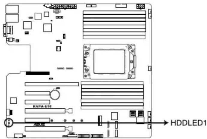
text_image
KNIPA-U16 ASCE HDDLED1KNPA-U16 Storage device activity LED
4.4 Internal connectors
1. Serial ATA connectors (7-pin SATA1-4)
These connectors, controlled by AMD integrated SATA controller, are for the Serial ATA signal cables for Serial ATA drives (SATA 1 connector is used for the optical drive by default).
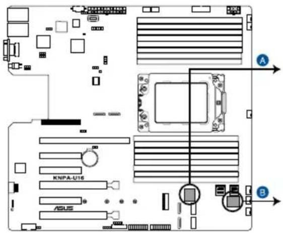
text_image
KNPA-U16 ASUS A BA

text_image
SATA1 GND RSATA_RXP1 RSATA_RXN1 GND RSATA_TXN1 RSATA_TXP1 GND SATA2 GND RSATA_RXP2 RSATA_RXN2 GND RSATA_TXN2 RSATA_TXP2 GNDB
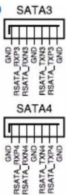
text_image
SATA3 GND RSATA_RXP3 RSATA_RXN3 GND RSATA_TXN3 RSATA_TXP3 GND SATA4 GND RSATA_RXP4 RSATA_RXN4 GND RSATA_TXN4 RSATA_TXP4 GNDKNPA-U16 SATA connectors

The actual data transfer rate depends on the speed of Serial ATA hard disks installed.
2. Power Supply SMBus connector (5-pin PSUSMB1)
This connector allows you to connect SMBus (System Management Bus) to the PSU (power supply unit) to read PSU information. Devices communicate with an SMBus host and/or other SMBus devices using the SMBus interface.
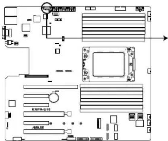
text_image
KNPA-U16 ASL25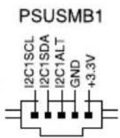
KNPA-U16 Power supply SMBus connector

This connector functions only when you enable ASUS ASMB9.
3. USB 3.0 connector (20-1 pin USB3\_34; 4-pin Type-A USB3\_4)
The 20-1 pin connector allows you to connect a USB 3.0 module for additional USB 3.0 front or rear panel ports. The 4-pin USB (Universal Serial Bus) Type-A port is available for connecting USB 3.0 devices.
text_image
USB3_34 A A B USB3_2 KNPA-U16 USB3_2 PIN 1 Vbus InIA_P3_SSRX- InIA_P3_SSRX+ GND InIA_P3_SSTX- InIA_P3_SSTX- GND InIA_P3_D- InIA_P3_D+ GND USB3_2KNPA-U16 USB 3.0 connectors
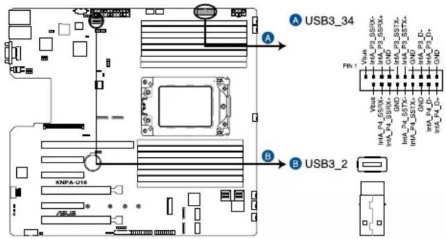
4. Serial port connector (10-1 pin COM1)
This connector is for the serial COM port. Connect the serial port module cable to one of these connectors, then install the module to a slot opening at the back of the system chassis.
text_image
COM1 PIN 1 RXD1 DTR1 DSR1 CTS1 DCD1 TXD1 GND RTS1# RT1#KNPA-U16 Serial port connector

The COM module is purchased separately.
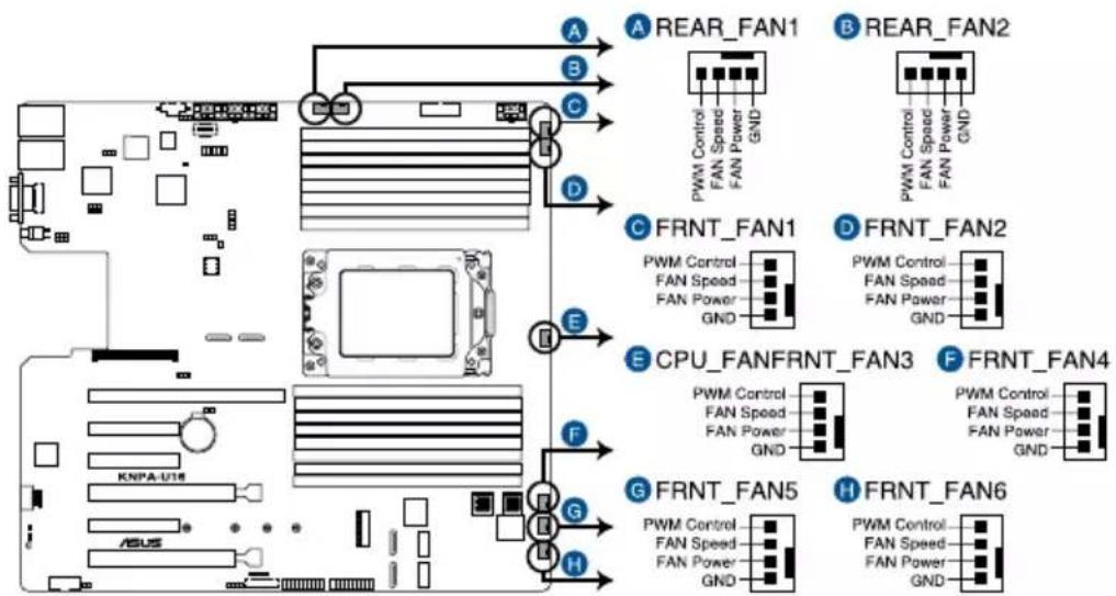
5. CPU, front, and rear fan connectors (4-pin FRNT\_FAN1-7, REAR\_FAN1-2)
The fan connectors support cooling fans. Connect the fan cables to the fan connectors on the motherboard, ensuring that the black wire of each cable matches the ground pin of the connector.

- DO NOT forget to connect the fan cables to the fan connectors. Insufficient air flow inside the system may damage the motherboard components.
• These are not jumpers! DO NOT place jumper caps on the fan connectors!
• All fans feature the ASUS Smart Fan technology.
flowchart
graph TD
    subgraph Module_A
        A1["REAR_FAN1"] --> A2["PWM Control"]
        A2 --> A3["FAN Power"]
        A3 --> A4["GND"]
    end
    subgraph Module_B
        B1["REAR_FAN2"] --> B2["PWM Control"]
        B2 --> B3["FAN Power"]
        B3 --> B4["GND"]
    end
    subgraph Module_C
        C1["FRNT_FAN1"] --> C2["PWM Control"]
        C2 --> C3["FAN Power"]
        C3 --> C4["GND"]
    end
    subgraph Module_D
        D1["FRNT_FAN2"] --> D2["PWM Control"]
        D2 --> D3["FAN Power"]
        D3 --> D4["GND"]
    end
    subgraph Module_E
        E1["CPU_FANFRNT_FAN3"] --> E2["PWM Control"]
        E2 --> E3["FAN Power"]
        E3 --> E4["GND"]
    end
    subgraph Module_F
        F1["FRNT_FAN4"] --> F2["PWM Control"]
        F2 --> F3["FAN Power"]
        F3 --> F4["GND"]
    end
    subgraph Module_G
        G1["FRNT_FAN5"] --> G2["PWM Control"]
        G2 --> G3["FAN Power"]
        G3 --> G4["GND"]
    end
    subgraph Module_H
        H1["FRNT_FAN6"] --> H2["PWM Control"]
        H2 --> H3["FAN Power"]
        H3 --> H4["GND"]
    end
KNPA-U16 FAN connectors
6. LAN Activity LED connector (5-1 pin LAN34\_LED1)
These leads are for 10G LAN activity LEDs on the front panel. Connect the LAN LED cable to the backplane for LAN activity indication.

text_image
LAN34_LED1 ③ ④ AUX_LAN3LINK# AUX_LAN3ACT# AUX_LAN4ACT# AUX_LAN4LINK# PIN1 KNPA-U16 ASL25KNPA-U16 LAN3 & LAN4 LED
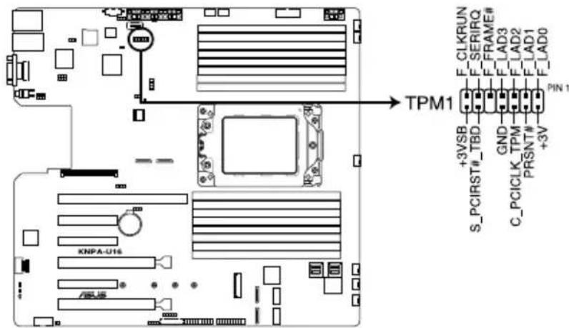
7. Trusted Platform Module connector (20-1 pin TPM1)
This connector supports a Trusted Platform Module (TPM) system, which can securely store keys, digital certificates, passwords, and data. A TPM system also helps enhance network security, protects digital identities, and ensures platform integrity.
text_image
TPM1 +3VSB S_PCIRST#_TBD GND C_PCICLK_TPM PRSNT# +3V F_CLKRUN F_SERIRQ F_FRAME# F_LAD3 F_LAD2 F_LAD1 F_LAD0 PIN 1KNPA-U16 TPM connector
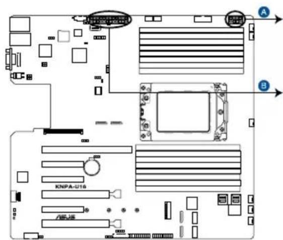
8. ATX power connectors (24-pin EATXPWR1, 8-pin EATX12V1)
These connectors are for the ATX power supply plugs. The power supply plugs are designed to fit these connectors in only one orientation. Find the proper orientation and push down firmly until the connectors completely fit.

- DO NOT forget to connect the 24-pin and the 8-pin power plugs; otherwise, the system will not boot up.
- Use of a power supply unit (PSU) with a higher power output is recommended when configuring a system with more power-consuming devices. The system may become unstable or may not boot up if the power is inadequate.
• This motherboard supports ATX2.0 PSU or later version. - Ensure that your PSU can provide at least the minimum power required by your system.
text_image
A B KNPA-U16 AEJ5EATX12V1

EATXPWR1

text_image
PN1 +3 Volts -12 Volts GND PSON# GND GND GND floating +5 Volts +5 Volts +5 Volts GND +3 Volts +3 Volts +5 V Standby +12 Volts +12 Volts GND GND Power OKKNPA-U16 ATX power connectors
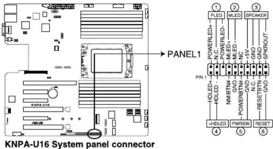
9. System panel connector (20-1 pin PANEL1)
This connector supports several chassis-mounted functions.
text_image
KNPA-U16 System panel connector PANEL1 ① PLED MLED SPEAKER POWERLED+ N.C. POWERLED- MLED MLED NC +5V GND GND SPKROUT PIN 1 HDLED+ HDLED - NMIBTN# GND POWERBTN# GND N.C. RESETBTN GND +HDLED PWRSW RESET ④ ⑤ ⑥1. System power LED (3-pin PLED)
This 3-pin connector is for the system power LED. Connect the chassis power LED cable to this connector. The system power LED lights up when you turn on the system power, and blinks when the system is in sleep mode.
2. Message LED (2-pin MLED)
This 2-pin connector is for the message LED cable that connects to the front message LED. The message LED is controlled by the BMC to indicate an abnormal event occurrence.
3. System warning speaker (4-pin SPEAKER)
This 4-pin connector is for the chassis-mounted system warning speaker. The speaker allows you to hear system beeps and warnings.
4. Hard disk drive activity LED (2-pin HDLED)
This 2-pin connector is for the HDD Activity LED. Connect the HDD Activity LED cable to this connector. The LED lights up or flashes when data is read from or written to the HDD.
5. ATX power button/soft-off button (2-pin PWRSW)
This connector is for the system power button. Pressing the power button turns the system on or puts the system in sleep or soft-off mode depending on the BIOS settings. Pressing the power switch for more than four seconds while the system is ON turns the system OFF.
6. Reset button (2-pin RESET)
This 2-pin connector is for the chassis-mounted reset button for system reboot without turning off the system power.
10. Auxiliary panel connector (20-2 pin AUX\_PANEL1, 20-pin AUX\_PANEL2)
This connector is for additional front panel features including front panel SMB, locator LED and switch, chassis intrusion, and LAN LEDs.
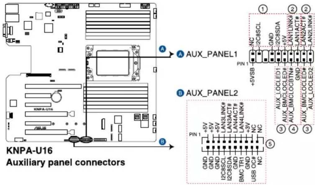
text_image
KNPA-U16 Auxiliary panel connectors A AUX_PANEL1 B AUX_PANEL2 PIN 1 +5VSB GND I2C8SCL I2C8SDA LAN3LINK# LAN3ACT# LAN4ACT# LAN4LINK# GND GND I2C8SCL I2C8SDA GND GND GND GND GND GND GND GND GND GND GND GND GND GND GND GND GND GND GND GND GND GND GND GND GND GND GND GND GND GND GND GND GND GND- Front panel SMB (6-1 pin FPSMB)
These leads connect the front panel SMBus cable.
- LAN activity LED (2-pin LAN1_LED, LAN2_LED)
These leads are for the Gigabit LAN activity LEDs on the front panel.
- Locator LED (2-pin LOCATORLED1, LOCATORLED2)
These leads are for the locator LED1 and LED2 on the front panel. Connect the Locator LED cables to these 2-pin connector. The LEDs will light up when the Locator button is pressed.
- Locator Button/Switch (2-pin LOCATORBTN)
These leads are for the locator button on the front panel. This button queries the state of the system locator.
- LAN activity LED and USB port (2-pin LAN3_LED, LAN4_LED, USB ports)
These leads are for the Gigabit LAN activity LEDs and USB ports on the front panel.
11. VGA connector (10-1 pin VGA\_HDR1)
This connector supports the VGA High Dynamic-Range interface.
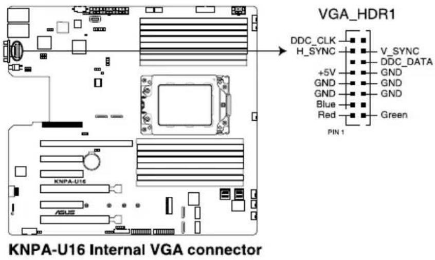
text_image
VGA_HDR1 DDC_CLK H_SYNC +5V GND GND Blue Red PIN 1 V_SYNC DDC_DATA GND GND GND Green KNPA-U16 Internal VGA connector12. Hard disk activity LED connector (4-pin HDLED1)
This LED connector is for the storage add-on card cable connected to the SATA or SAS add-on card. The read or write activities of any device connected to the SATA or SAS add-on card causes the front panel LED to light up.
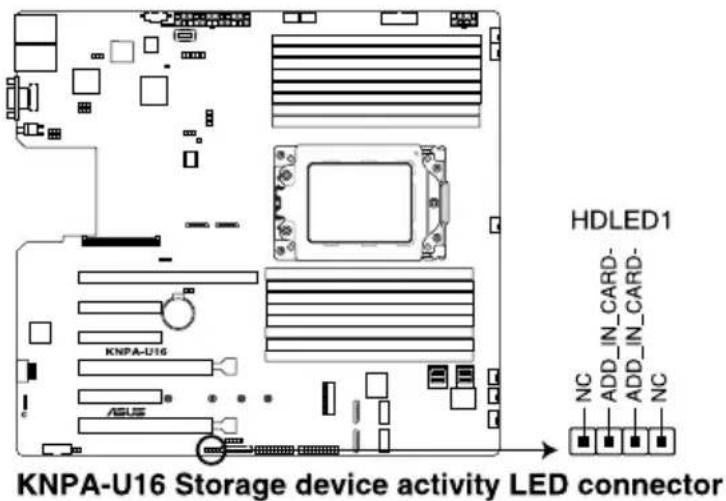
text_image
KNPA-U16 Storage device activity LED connector HDLED1 NC ADD_IN_CARD- ADD_IN_CARD- NC13. Chassis Intrusion connectors (2-pin INTRUSION)
This lead is for the intrusion detection feature for chassis with intrusion sensor or microswitch. When you remove any chassis component, the sensor triggers and sends a high level signal to these leads to record a chassis intrusion event. The default setting is short CASEOPEN and GND pin by jumper cap to disable the function.

text_image
INTRUSION CHASSIS# GND PIN 1 KNPA-U1s RSJSKNPA-U16 Chassis Intrusion connector
14. OCUPCIE connectors (MPCIE\_HD1-6)
Connects the PCIE signal to the NVME port on the backplane.
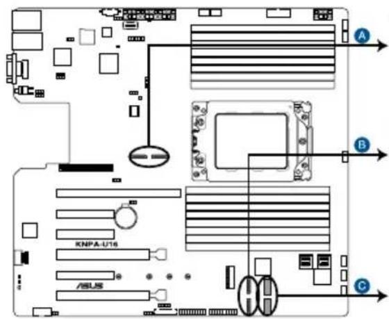
text_image
A B C KNPA-U16 ASUS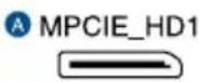

text_image
MPCIE_HD4 MPCIE_HD3
text_image
MPCIE_HD6 MPCIE_HD5KNPA-U16 MPCIE_HD connectors
15. M.2 (NGFF) connectors (NGFF1)
This connector allows you to install M.2 devices.

text_image
KNPA-U16 ASUS NGFF1KNPA-U16 NGFF connector

This connector supports type 2242/2260/2280/22110 devices on both PCI-E and SATA interface.

The M.2 (NGFF) device is purchased separately.
16. Mezzanine PCIE card connectors (MEZZPCIE1)
The MEZZPCIE1 connector supports Open Compute Project (OCP) cards.

text_image
MEZZPCIE1 KNPA-U16 ASUSKNPA-U16 MEZZPCIE connector
17. OCP LAN Activity LED connector (4-1 pin OCP\_LED1)
OCP LAN LED connector supports OCP LAN card Active LED.

text_image
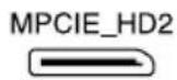
KNPA-U16 OCP_LED1 connector OCP_LED1 LAN3LINK# LAN4LINK# NC PIN 118. Micro SD card slot (MSD1)
Your motherboard supports SD Memory Card v2.00 (SDHC) / v3.00 (SDXC).
text_image
KNPA-U16 MSD1 MSD1
Disconnect all power (including redundant PSUs) from the existing system before you add or remove a Memory Card, then reboot the system to access the Memory Card.
- This Micro SD card slot functions only when you enable ASUS ASMB9.
- Some memory cards may not be compatible with your motherboard. Ensure that you use only compatible memory cards to prevent loss of data, damage to your device, or memory card, or both.
19. Mini-SAS HD connectors (ISATA1-2)
This motherboard comes with mini Serial Attached SCSI (SAS) HD connectors, the storage technology that supports Serial ATA. Each connector supports up to four devices.

text_image
KNIPA-U16 ASUS ISATA1 ISATA2KNPA-U16 ISATA connectors
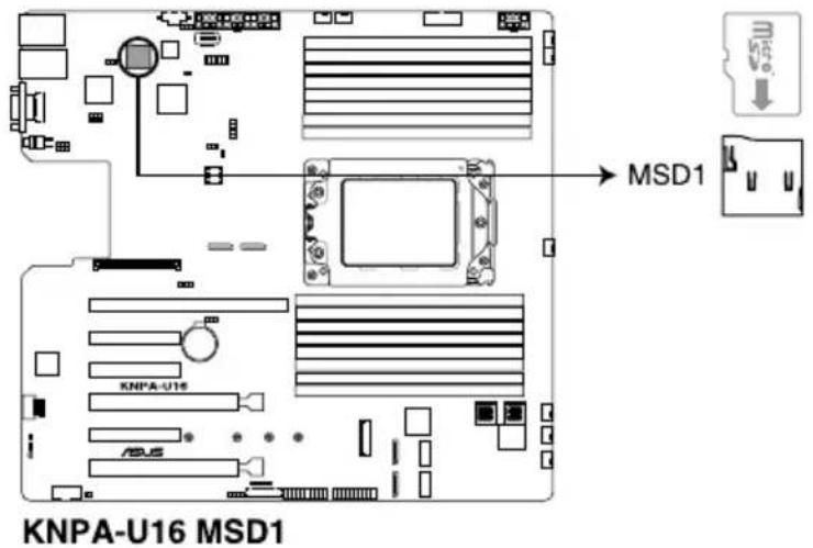
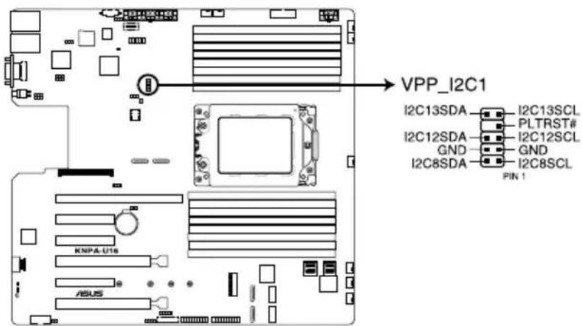
20. VPP\_I2C1 connector (10-1 pin VPP\_I2C1)
This connector is used for the Intel VMD function and sensor readings.
text_image
VPP_I2C1 I2C13SDA I2C13SCL PLTRST# I2C12SDA I2C12SCL GND GND I2C8SDA I2C8SCL PIN 1 KNPA-U16 ASUSKNPA-U16 VPP_I2C1 connector
BIOS Setup
This chapter tells how to change the system settings through the BIOS Setup menus. Detailed descriptions of the BIOS parameters are also provided.
5
5.1 Managing and updating your BIOS
The following utilities allow you to manage and update the motherboard Basic Input/Output System (BIOS) setup:
1. ASUS CrashFree BIOS 3
To recover the BIOS using a bootable USB flash disk drive when the BIOS file fails or gets corrupted.
2. ASUS EzFlash
Updates the BIOS using a USB flash disk.
3. BUPDATER
Updates the BIOS in DOS mode using a bootable USB flash disk drive.
Refer to the corresponding sections for details on these utilities.

Save a copy of the original motherboard BIOS file to a bootable USB flash disk drive in case you need to restore the BIOS in the future. Copy the original motherboard BIOS using the BUPDATER utility.
5.1.1 ASUS CrashFree BIOS 3 utility
The ASUS CrashFree BIOS 3 is an auto recovery tool that allows you to restore the BIOS file when it fails or gets corrupted during the updating process. You can update a corrupted BIOS file using a USB flash drive that contains the updated BIOS file.

Prepare a USB flash drive containing the updated motherboard BIOS before using this utility.
Recovering the BIOS from a USB flash drive
To recover the BIOS from a USB flash drive:
- Insert the USB flash drive with the original or updated BIOS file to one USB port on the system.
- The utility will automatically recover the BIOS. It resets the system when the BIOS recovery finished.

DO NOT shut down or reset the system while recovering the BIOS! Doing so would cause system boot failure!

The recovered BIOS may not be the latest BIOS version for this motherboard. Visit the ASUS website at www.asus.com to download the latest BIOS file.
5.1.2 ASUS EZ Flash Utility
The ASUS EZ Flash Utility feature allows you to update the BIOS without having to use a DOS-based utility.

Before you start using this utility, download the latest BIOS from the ASUS website at www.asus.com.
To update the BIOS using EZ Flash Utility:
- Insert the USB flash disk that contains the latest BIOS file into the USB port.
- Enter the BIOS setup program. Go to the Tool menu then select ASUS EZ Flash Utility. Press
.
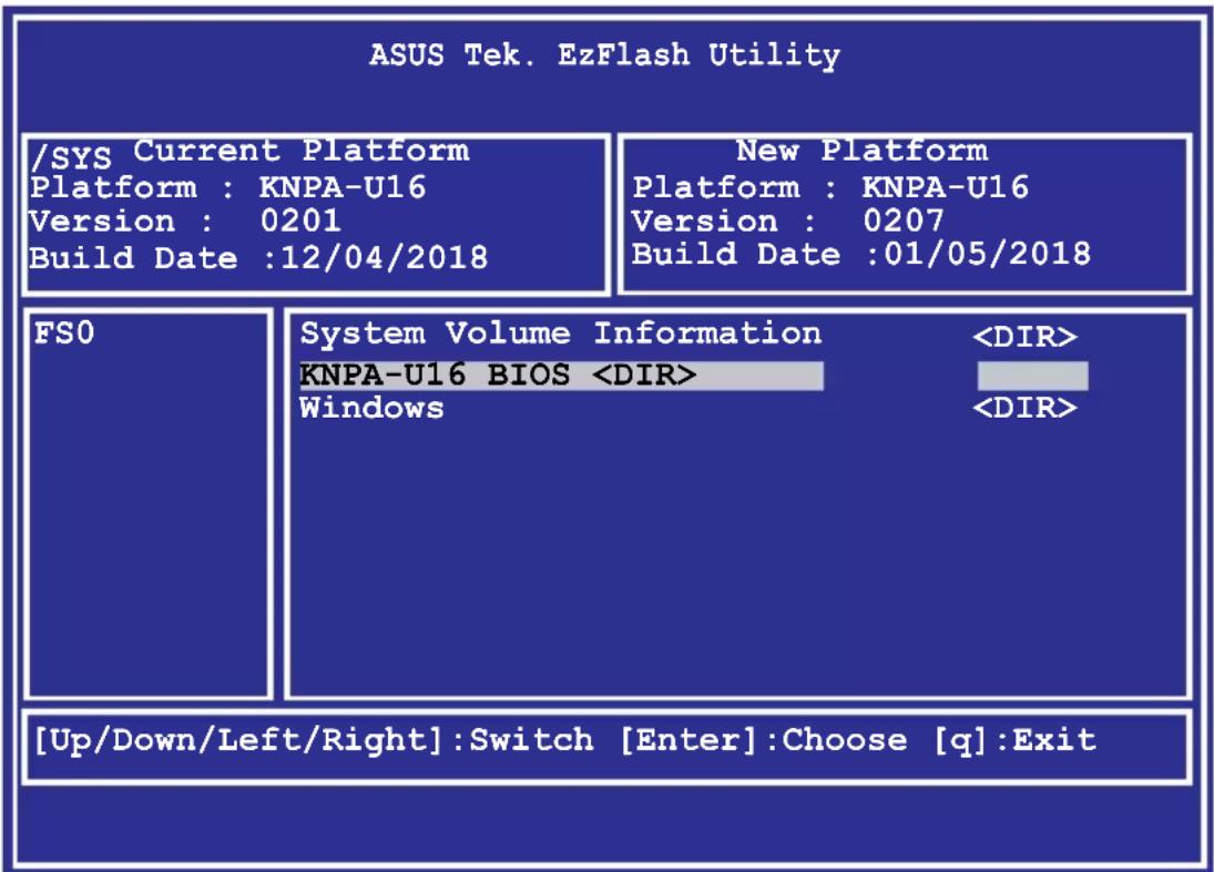
text_image
ASUS Tek. EzFlash Utility /SYS Current Platform Platform : KNPA-U16 Version : 0201 Build Date :12/04/2018 New Platform Platform : KNPA-U16 Version : 0207 Build Date :01/05/2018 FSO System Volume Information- Press
to switch to the Drive field. - Press the Up/Down arrow keys to find the USB flash disk that contains the latest BIOS, then press
. -
Press
to switch to the Folder Info field. -
Press the Up/Down arrow keys to find the BIOS file, and then press
to perform the BIOS update process. Reboot the system when the update process is done.

- This function can support devices such as a USB flash disk with FAT 32/16 format and single partition only.
- DO NOT shut down or reset the system while updating the BIOS to prevent system boot failure!

Ensure to load the BIOS default settings to ensure system compatibility and stability. Press
5.1.3 BUPDATER utility

The succeeding BIOS screens are for reference only. The actual BIOS screen displays may not be the same as shown.
The BUPDATER utility allows you to update the BIOS file in the DOS environment using a bootable USB flash disk drive with the updated BIOS file.
Updating the BIOS file
To update the BIOS file using the BUPDATER utility:
- Visit the ASUS website at www.asus.com and download the latest BIOS file for the motherboard. Save the BIOS file to a bootable USB flash disk drive.
- Copy the BUPDATER utility (BUPDATER.exe) from the ASUS support website at https://www.asus.com/support to the bootable USB flash disk drive you created earlier.
- Boot the system in DOS mode, then at the prompt, type:
BUPDATER /i [filename].CAP
where [filename] is the latest or the original BIOS file on the bootable USB flash disk drive, then press
A:>BUPDATER /i [file name].CAP
- The utility verifies the file, then starts updating the BIOS file.
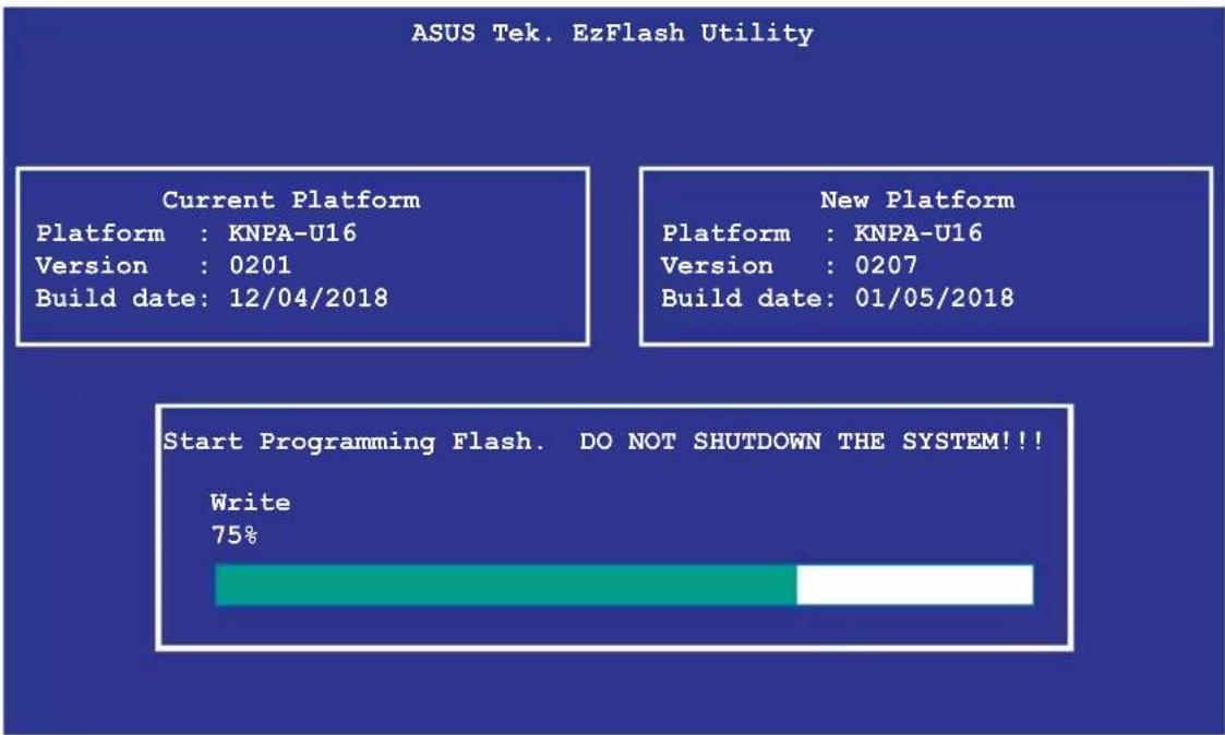
text_image
ASUS Tek. EzFlash Utility Current Platform Platform : KNPA-U16 Version : 0201 Build date: 12/04/2018 New Platform Platform : KNPA-U16 Version : 0207 Build date: 01/05/2018 Start Programming Flash. DO NOT SHUTDOWN THE SYSTEM!!! Write 75%
DO NOT shut down or reset the system while updating the BIOS to prevent system boot failure!
- The utility returns to the DOS prompt after the BIOS update process is completed. Reboot the system from the hard disk drive.
The BIOS update is finished! Please restart your system.
C:\>
5.2 BIOS setup program
This motherboard supports a programmable firmware chip that you can update using the provided utility described in section 5.1 Managing and updating your BIOS.
Use the BIOS Setup program when you are installing a motherboard, reconfiguring your system, or prompted to "Run Setup." This section explains how to configure your system using this utility.
Even if you are not prompted to use the Setup program, you can change the configuration of your computer in the future. For example, you can enable the security password feature or change the power management settings. This requires you to reconfigure your system using the BIOS Setup program so that the computer can recognize these changes and record them in the CMOS RAM of the firmware chip.
The firmware chip on the motherboard stores the Setup utility. When you start up the computer, the system provides you with the opportunity to run this program. Press during the Power-On Self-Test (POST) to enter the Setup utility; otherwise, POST continues with its test routines.
If you wish to enter Setup after POST, restart the system by pressing
The Setup program is designed to make it as easy to use as possible. Being a menu-driven program, it lets you scroll through the various sub-menus and make your selections from the available options using the navigation keys.

- The default BIOS settings for this motherboard apply for most conditions to ensure optimum performance. If the system becomes unstable after changing any BIOS settings, load the default settings to ensure system compatibility and stability. Press
and select Yes to load the BIOS default settings. - The BIOS setup screens shown in this section are for reference purposes only, and may not exactly match what you see on your screen.
- Visit the ASUS website (www.asus.com) to download the latest BIOS file for this motherboard.
5.2.1 BIOS menu screen
General helpMenu bar Configuration fieldsM

text_image
Aptio Setup Utility - Copyright (C) 2018 American Megatrends, Inc. Main Advanced Chipset Security Boot Tool Save & Exit AND CBS Event Logs Server Ngmt BIOS Information BIOS Vendor Core Version Compliance Project Version Build Date EMC Firmware Revision System Serial Number Agesa Version Memory Information Total Memory Memory Frequency BIOS Sub Version System Date System Time Access Level INTEL LAN1 MAC: INTEL LAN2 MAC: American Megatrends 5.13 UEFI 2.6: PI 1.4 0301 x64 08/09/2018 1.12 System Serial Number v1.0.0.7 9192 MD 2133 MT/s S18080903 [Thu 08/16/2018] [15:31:20] Administrator Set the Date. Use Tab to switch between Date elements. Default Ranges: Year: 2005-2099 Months: 1-12 Days: dependent on month ++: Select Screen ↑↓: Select Item Enter: Select +/-: Change Opt. F1: General Help F2: Previous Values F5: Optimized Defaults F10: Save Changes & Reset F12: Print Screen ESC: Exit version 2.10.1264. Copyright (C) 2018 American Megatrends, Inc. Navigation keys5.2.2 Menu bar
The menu bar on top of the screen has the following main items:
Main For changing the basic system configuration
Advanced For changing the advanced system settings
Chipset For changing the chipset settings
Security For changing the security settings
Boot For changing the system boot configuration
Tool For configuring options for special functions
Save & Exit For selecting the exit options
AMD CBS For configuring AMD CBS settings
Event Logs For changing the event log settings
Server Mgmt For changing the Server Mgmt settings
To select an item on the menu bar, press the right or left arrow key on the keyboard until the desired item is highlighted.
5.2.3 Menu items
The highlighted item on the menu bar displays the specific items for that menu. For example, selecting Main shows the Main menu items.
The other items (such as Advanced) on the menu bar have their respective menu items.
5.2.4 Submenu items
A solid triangle before each item on any menu screen means that the item has a submenu. To display the submenu, select the item then press
5.2.5 Navigation keys
At the bottom right corner of a menu screen are the navigation keys for the BIOS setup program. Use the navigation keys to select items in the menu and change the settings.
5.2.6 General help
At the top right corner of the menu screen is a brief description of the selected item.
5.2.7 Configuration fields
These fields show the values for the menu items. If an item is user-configurable, you can change the value of the field opposite the item. You cannot select an item that is not user-configurable.
A configurable field is enclosed in brackets, and is highlighted when selected. To change the value of a field, select it and press
5.2.8 Pop-up window
Select a menu item and press
5.2.9 Scroll bar
A scroll bar appears on the right side of a menu screen when there are items that do not fit on the screen. Press the Up / Down arrow keys or
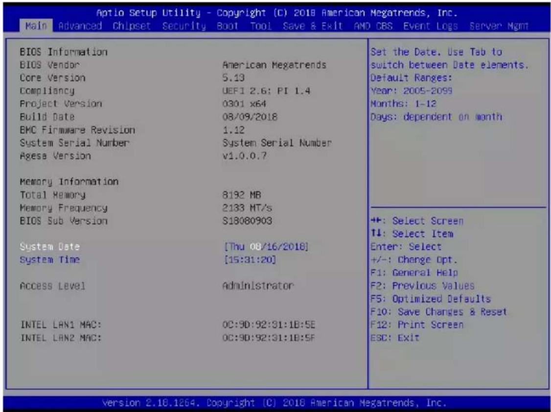
5.3 Main menu
When you enter the BIOS Setup program, the Main menu screen appears. The Main menu provides you an overview of the basic system information, and allows you to set the system date, time, language, and security settings.
text_image
Aptio Setup Utility - Copyright (C) 2018 American Megatrends, Inc. Main Advanced Chipset Security Boot Tool Save & Exit AND CBS Event Logs Server Mgmt BIOS Information BIOS Vendor American Megatrends Core Version 5.13 Compliance UEFI 2.6: PI 1.4 Project Version 0301 x64 Build Date 08/09/2018 BMC Firmware Revision 1.12 System Serial Number System Serial Number Agesa Version v1.0.0.7 Memory Information Total Memory 8192 MB Memory Frequency 2133 MT/s BIOS Sub Version S18080903 System Date [Thu 08/16/2018] System Time [15:31:20] Access Level Administrator INTEL LAN1 MAC: OC:9D:92:31:1B:5E INTEL LAN2 MAC: OC:9D:92:31:1B:5F Set the Date. Use Tab to switch between Date elements. Default Ranges: Year: 2005-2099 Months: 1-12 Days: dependent on month ++: Select Screen T↓: Select Item Enter: Select +/-: Change Opt. F1: General Help F2: Previous Values F5: Optimized Defaults F10: Save Changes & Reset F12: Print Screen ESC: Exit version 2.10.1264. Copyright (C) 2018 American Megatrends, Inc.5.3.1 System Date [Day xx/xx/xxxx]
Allows you to set the system date.
5.3.2 System Time [xx:xx:xx]
Allows you to set the system time.
5.4 Advanced menu
The Advanced menu items allow you to change the settings for the CPU and other system devices.

Take caution when changing the settings of the Advanced menu items. Incorrect field values can cause the system to malfunction.

text_image
Aptio Setup Utility - Copyright (C) 2018 American Megatrends, Inc. Main Advanced Chipset Security Boot Tool Save & Exit AND CBS Event Logs Server Mgmt Trusted Computing PSP Firmware Versions APM SMART Settings NCT6798D Super IO Configuration Onboard LAN Configuration Serial Port Console Redirection CPU Configuration PCI Subsystem Settings Network Stack Configuration CSM Configuration NVMe Configuration NVMe Hotplug [Disabled] SATA Configuration USB Configuration iSCSI Configuration Trusted Computing Settings +/-: Select Screen ↑↓: Select Item Enter: Select +/−: Change Opt. F1: General Help F2: Previous Values FS: Optimized Defaults F10: Save Changes & Reset F12: Print Screen ESC: Exit Version 2.18.1264. Copyright (C) 2018 American Megatrends, Inc.NVMe Hotplug [Disabled]
[Disabled] Disables NVMe Hotplug.
[Enabled] Enables NVMe Hotplug.
5.4.1 Trusted Computing

text_image
Aptio Setup Utility - Copyright (C) 2018 American Megatrends, Inc. Advanced Configuration Security Device Support [Enable] NO Security Device Found Enables or Disables BIOS support for security device. U.S. will not show Security device. TCG EFI protocol and INTIA Interface will not be available.Configuration
Security Device Support [Enabled]
Allows you to enable or disable the BIOS support for security device.
Configuration options: [Disabled] [Enabled]
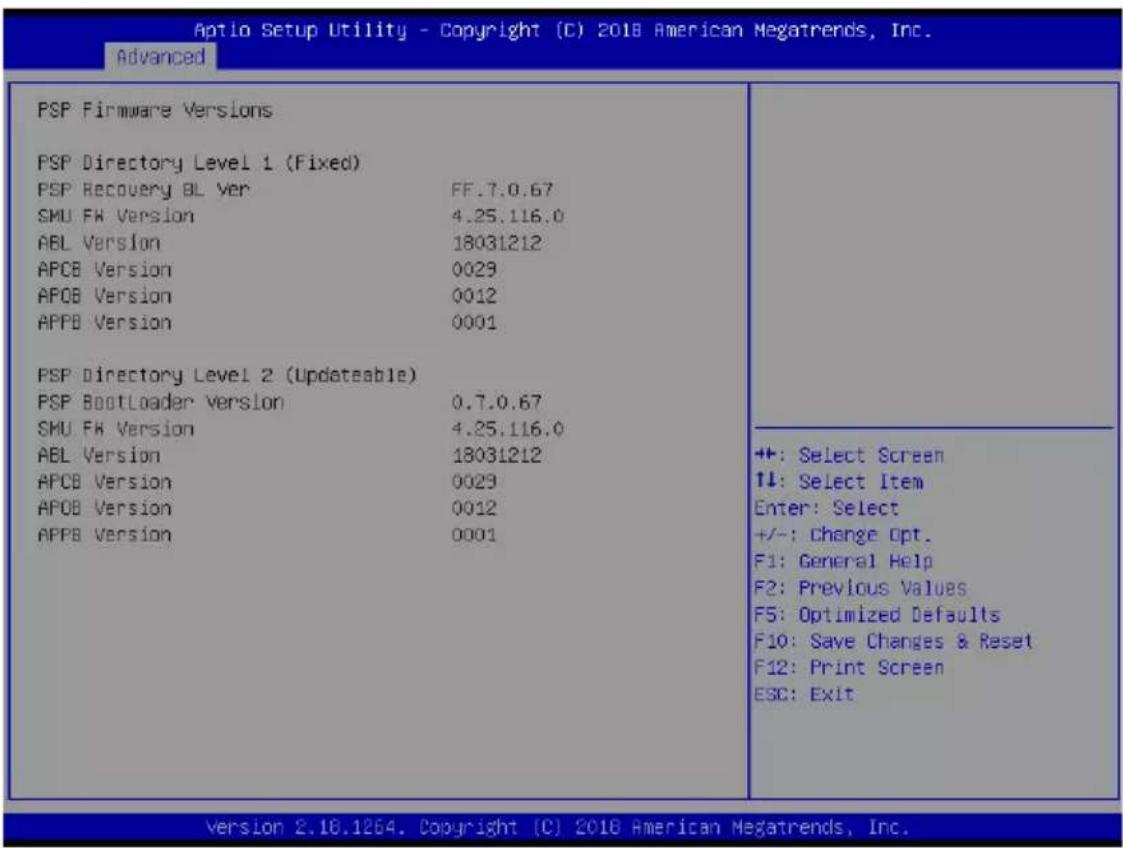
5.4.2 PSP Firmware Versions
This page displays the PSP firmware versions.
text_image
Aptio Setup Utility - Copyright (C) 2018 American Megatrends, Inc. Advanced PSP Firmware Versions PSP Directory Level 1 (Fixed) PSP Recovery BL Ver FF.7.0.67 SMU FW Version 4.25.116.0 ABL Version 18031212 APCB Version 0029 APOB Version 0012 APPB Version 0001 PSP Directory Level 2 (Updateable) PSP BootLoader Version 0.7.0.67 SMU FW Version 4.25.116.0 ABL Version 18031212 APCB Version 0029 APOB Version 0012 APPB Version 0001 ++: Select Screen ↑↓: Select Item Enter: Select +/−: Change Opt. F1: General Help F2: Previous Values F5: Optimized Defaults F10: Save Changes & Reset F12: Print Screen ESC: Exit Version 2.10.1264. Copyright (C) 2018 American Megatrends, Inc.5.4.3 APM
Allows you to configure the Advance Power Management (APM) settings.
| Aptio Setup Utility - Copyright (C) 2018 American Megatrends, Inc. | ||
| Advanced | ||
| Restore AC Power Loss [Last State] Power On By PCIE [Disabled] Power On By RTC [Disabled] | Specify what state to go to when power is re-applied after a power failure (G3 state). | |
Restore AC Power Loss [Last State]
When set to [Power Off], the system goes into off state after an AC power loss. When set to [Power On], the system will reboot after an AC power loss. When set to [Last State], the system goes into either off or on state, whatever the system state was before the AC power loss.
Configuration options: [Power Off] [Power On] [Last State]
Power On By PCIE [Disabled]
[Disabled] Disables the PCIE devices to generate a wake event.
[Enabled] Enables the PCIE devices to generate a wake event.
Power On By RTC [Disabled]
[Disabled] Disables RTC to generate a wake event.
[Enabled] When set to [Enabled], the items RTC Alarm Date (Days) and Hour/Minute/Second will become user-configurable with set values.
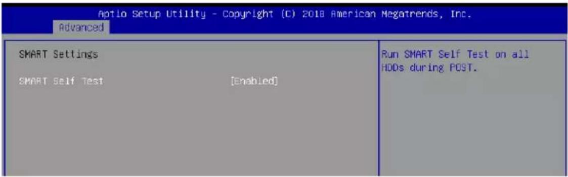
5.4.4 Smart Settings
text_image
Aptio Setup Utility - Copyright (C) 2018 American Megatrends, Inc. Advanced SMART Settings SMART Self Test [Enabled] Run SMART Self Test on all HDDs during POST.SMART Self Test [Enabled]
Allows you to run SMART Self Test on all HDDs during POST.
Configuration options: [Disabled] [Enabled]
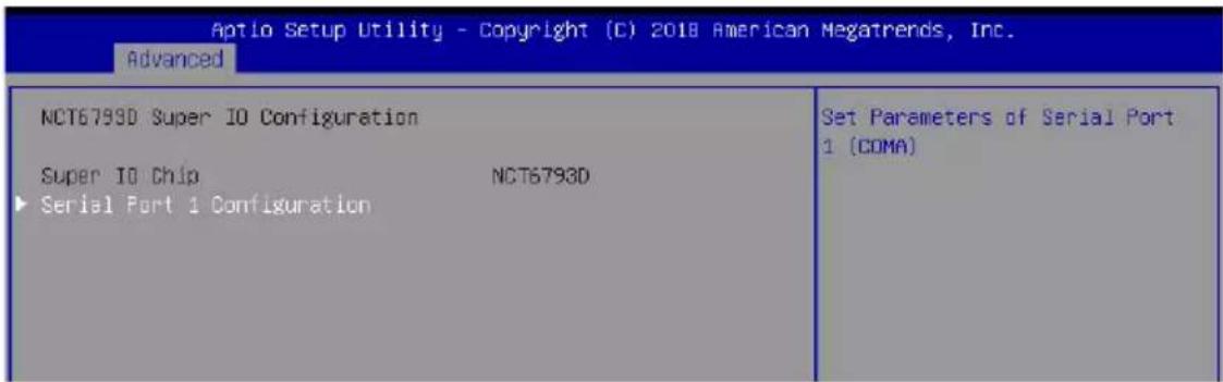
5.4.5 NCT6793D Super IO Configuration
text_image
Aptio Setup Utility - Copyright (C) 2018 American Megatrends, Inc. Advanced NCT6793D Super IO Configuration Super IO Chip NCT6793D ▶ Serial Port 1 Configuration Set Parameters of Serial Port 1 (COMA)Serial Port 1 Configuration
Allows you to set the parameters of Serial Port 1.
Serial Port [Enabled]
Allows you to enable or disable Serial Port.
Configuration options: [Disabled] [Enabled]
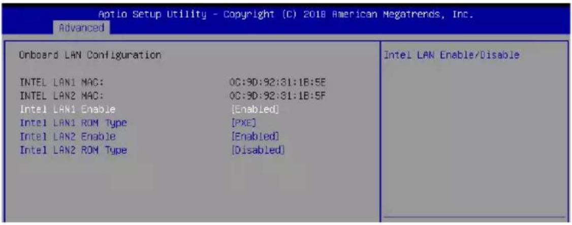
5.4.6 Onboard LAN Configuration
text_image
Aptio Setup Utility - Copyright (C) 2018 American Megatrends, Inc. Advanced Onboard LAN Configuration INTEL LAN1 MAC: OC:9D:92:31:1B:5E INTEL LAN2 MAC: OC:9D:92:31:1B:5F Intel LAN1 Enable [Enabled] Intel LAN1 ROM Type [PXE] Intel LAN2 Enable [Enabled] Intel LAN2 ROM Type [Disabled] Intel LAN Enable/DisableIntel LAN1 Enable [Enabled]
Allows you to enable or disable the Intel LAN.
Configuration options: [Disabled] [Enabled]
![ASUS RS500A-E9-PS4 - Intel LAN1 Enable [Enabled] - 1](/content/2026/06/1202776/images/e3de5957b642c00526f05aeffff37afbab1ca118ff5c918243ff34bb0f163ea4.jpg)
The following items appear only when Intel LAN1 Enable is set to [Enabled].
Intel LAN 1 ROM Type [PXE]
Allows you to select the Intel LAN ROM type.
Configuration options: [PXE] [iSCSI] [Disabled]
Intel LAN2 Enable [Enabled]
Allows you to enable or disable the Intel LAN.
Configuration options: [Disabled] [Enabled]
![ASUS RS500A-E9-PS4 - Intel LAN2 Enable [Enabled] - 1](/content/2026/06/1202776/images/82005e0caadd645433156a3fdb61d06f2859dd6787dc468469e8f09793b40fa9.jpg)
The following items appear only when Intel LAN2 Enable is set to [Enabled].
Intel LAN 2 ROM Type [Disabled]
Allows you to select the Intel LAN ROM type.
Configuration options: [PXE] [iSCSI] [Disabled]
5.4.7 Serial Port Console Redirection

text_image
Aptio Setup Utility - Copyright (C) 2018 American Megatrends, Inc. Advanced COM1 Console Redirection [Disabled] ► Console Redirection Settings COM2 Console Redirection [Disabled] ► Console Redirection Settings Legacy Console Redirection ► Legacy Console Redirection Settings Serial Port for Out-of-Band Management/ Windows Emergency Management Services (EMS) Console Redirection [Disabled] ► Console Redirection Settings Console Redirection Enable or Disable. ++: Select Screen ↑↓: Select Item Enter: Select +/-: Change Opt.COM1/COM2
Console Redirection [Disabled]
Allows you to enable or disable the console redirection feature.
Configuration options: [Disabled] [Enabled]
![ASUS RS500A-E9-PS4 - Console Redirection [Disabled] - 1](/content/2026/06/1202776/images/8f56c42440242cd3730550e198aad274cb1a9a7aa79f648e09e72f9207cda61e.jpg)
The following item appears only when you set Console Redirection to [Enabled].
Console Redirection Settings
These items become configurable only when you enable the Console Redirection item. The settings specify how the host computer and the remote computer (which the user is using) will exchange data. Both computers should have the same or compatible settings.
Terminal Type [VT-UTF8]
Allows you to set the terminal type.
[VT100] ASCII char set.
[VT100+] Extends VT100 to support color, function keys, etc.
[VT-UTF8] Uses UTF8 encoding to map Unicode chars onto 1 or more bytes.
[ANSI] Extended ASCII char set.
Bits per second [57600]
Selects serial port transmission speed. The speed must be matched on the other side.
Long or noisy lines may require lower speeds.
Configuration options: [9600] [19200] [38400] [57600] [115200]
Data Bits [8]
Configuration options: [7] [8]
Parity [None]
A parity bit can be sent with the data bits to detect some transmission errors. [Mark] and [Space] parity do not allow for error detection.
[None] None
[Even] parity bit is 0 if the num of 1's in the data bits is even
[Odd] parity bit is 0 if num of 1's in the data bits is odd
[Mark] parity bit is always 1
[Space] parity bit is always 0
Stop Bits [1]
Stop bits indicate the end of a serial data packet. (A start bit indicates the beginning.) The standard setting is 1 stop bit. Communication with slow devices may require more than 1 stop bit.
Configuration options: [1] [2]
Flow Control [Hardware RTS/CTS]
Flow control can prevent data loss from buffer overflow. When sending data, if the receiving buffers are full, a “stop” signal can be sent to stop the data flow. Once the buffers are empty, a “start” signal can be sent to re-start the flow. Hardware flow control uses two wires to send start/stop signals.
Configuration options: [None] [Hardware RTS/CTS]
VT -UTF8 Combo Key Support [Enabled]
This allows you to enable the VT -UTF8 Combination Key Support for ANSI/VT100 terminals.
Configuration options: [Disabled] [Enabled]
Recorder Mode [Disabled]
With this mode enabled only text will be sent. This is to capture Terminal data.
Configuration options: [Disabled] [Enabled]
Putty Keypad [VT100]
This allows you to select the FunctionKey and Keypad on Putty.
Configuration options: [VT100] [LINUX] [XTERMR6] [SCO] [ESCN] [VT400]
Legacy Console Redirection Settings
Legacy Console Redirection Port [COM1]
Allows you to select a COM port to display redirection of Legacy OS and Legacy OPROM Messages.
Configuration options: [COM1] [COM2]
Serial Port for Out-of-Band Management/Windows Emergency Management Services (EMS)
Console Redirection [Disabled]
Allows you to enable or disable the console redirection feature.
Configuration options: [Disabled] [Enabled]
![ASUS RS500A-E9-PS4 - Console Redirection [Disabled] - 1](/content/2026/06/1202776/images/35259337c34bf7539b183edecd7f0da42b8350ea21459baeb9caeb01dafda778.jpg)
The following item appears only when you set Console Redirection to [Enabled].
Console Redirection Settings
Out-of-Band Mgmt Port [COM1]
Microsoft Windows Emergency Management Services (EMS) allow for remote management of a Windows Server OS through a serial port.
Configuration options: [COM1] [COM2]
Terminal Type [VT-UTF8]
Microsoft Windows Emergency Management Services (EMS) allow for remote management of a Windows Server OS through a serial port.
Configuration options: [VT100] [VT100+] [VT-UTF8] [ANSI]
Bits per second [115200]
Microsoft Windows Emergency Management Services (EMS) allow for remote management of a Windows Server OS through a serial port.
Configuration options: [9600] [19200] [57600] [115200]
Flow Control [None]
Microsoft Windows Emergency Management Services (EMS) allow for remote management of a Windows Server OS through a serial port.
Configuration options: [None] [Hardware RTS/CTS] [Software Xon/Xoff]
5.4.8 CPU Configuration
This page displays the CPU node information.
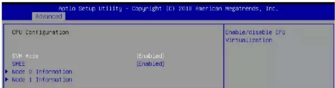
text_image
Aptlo Setup Utility - Copyright (C) 2018 American Megatrends, Inc. Advanced CPU Configuration SVH Mode [Enabled] SMEE [Enabled] ► Node 0 Information ► Node 1 Information Enable/disable CPU VirtualizationSVM Mode [Enabled]
Allows you to enable or disable SVM Mode.
Configuration options: [Disabled] [Enabled]
SMEE [Enabled]
Allows you to enable or disable SMEE.
Configuration options: [Disabled] [Enabled]
5.4.9 PCI Subsystem Settings
Allows you to configure PCI, PCI-X, and PCI Express Settings.
| PCI Bus Driver Version | A5.01.12 | Enables or Disables VGA Palette Registers Snooping. |
| PCI Devices Common Settings: VGA Palette Snoop | [Disabled] | |
| VGA Priority | [Offboard Device] | |
| Load RT32 Image | [Disabled] | |
| Above 4G Decoding | [Disabled] | |
| SR-IOV Support | [Disabled] |
VGA Palette Snoop [Disabled]
This option enables or disables VGA Palette Registers Snooping.
Configuration options: [Disabled] [Enabled]
VGA Priority [Offboard Device]
This option allows you to select the priority of the VGA.
Configuration options: [Offboard Device] [Onboard Device]
Load RT32 Image [Disabled]
This option enables or disables RT32 Image Loading.
Configuration options: [Disabled] [Enabled]
Above 4G Decoding [Disabled]
Allows you to enable or disable 64-bit capable devices to be decoded in above 4G address space. It only works if the system supports 64-bit PCI decoding.
Configuration options: [Disabled] [Enabled]
SR-IOV Support [Disabled]
This option enables or disables Single Root IO Virtualization Support if the system has SR-IOV capable PCIe devices.
Configuration options: [Disabled] [Enabled]
5.4.10 Network Stack Configuration
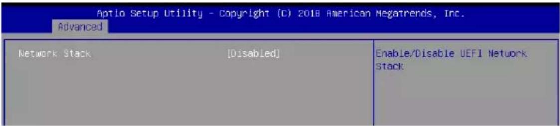
text_image
Aptio Setup Utility - Copyright (C) 2018 American Megatrends, Inc. Advanced Network Stack [Disabled] Enable/Disable UEFI Network StackNetwork stack [Disabled]
Enables or disables the network stack feature.
Configuration options: [Disable] [Enable]
![ASUS RS500A-E9-PS4 - Network stack [Disabled] - 1](/content/2026/06/1202776/images/f5cfb2edc8c677de9b40769c4f0e3accc8082791e6719cb3ddbc5d166a6f5673.jpg)
The following item appears only when Network stack is set to [Enabled].
Ipv4 PXE Support [Disabled]
Enables or disables the lpv4 PXE Boot Support. If disabled, lpv4 PXE boot option will not be created.
Configuration options: [Disabled] [Enabled]
Ipv4 HTTP Support [Disabled]
Enables or disables the lpv4 HTTP Boot Support. If disabled, lpv4 HTTP boot option will not be created.
Configuration options: [Disabled] [Enabled]
Ipv6 PXE Support [Disabled]
Enables or disables the lpv6 PXE Boot Support. If disabled, lpv6 PXE boot option will not be created.
Configuration options: [Disabled] [Enabled]
Ipv6 HTTP Support [Disabled]
Enables or disables the lpv6 HTTP Boot Support. If disabled, lpv6 HTTP boot option will not be created.
Configuration options: [Disabled] [Enabled]
IP6 Configuration Policy [Automatic]
This item allows you to st the IP6 Configuration policy.
Configuration options: [Automatic] [Manual]
PXE boot wait time [0]
Wait time to press ESC key to abort the PXE boot.
Media detect time [1]
Wait time (in seconds) to detect media.
5.4.11 CSM Configuration
| Aptlo Setup Utility - Copyright (C) 2018 American Megatrends, Inc. Advanced | |
| Compatibility Support Module Configuration | |
| CSM Support | [Enabled] |
| CSM16 Module Version | 07.80 |
| GateA20 Active | [Upon Request] |
| Option ROM Messages | [Force BIOS] |
| INT19 Trap Response | [Immediate] |
| Boot option filter | [Legacy only] |
| Option ROM execution | |
| Network | [Legacy] |
| Storage | [Legacy] |
| Video | [Legacy] |
| Other PCI devices | [Legacy] |
| +/-: Select Screen ↑↓: Select Item Enter: Select +/-: Change Opt. F1: General Help F2: Previous Value | |
CSM Support [Enabled]
This option allows you to enable or disable CSM Support.
Configuration options: [Disabled] [Enabled]
![ASUS RS500A-E9-PS4 - CSM Support [Enabled] - 1](/content/2026/06/1202776/images/5fdf9595153e7a5865c523e2f3acd216874ab6bb23e9d5a16e747736a631c1a2.jpg)
The following item appears only when CSM Support is set to [Enabled].
GateA20 Active [Upon Request]
This allows you to set the GA20 option.
Configuration options: [Upon Request] [Always]
Option ROM Messages [Force BIOS]
This allows you to set the display mode for option ROM.
Configuration options: [Force BIOS] [Keep Current]
INT19 Trap Response [Immediate]
[Immediate] Execute the trap right away.
[Postponed] Execute the trap during legacy boot.
Boot Option filter [Legacy only]
This option allows you to control the Legacy/UEFI ROMs priority.
Configuration options: [UEFI and Legacy] [Legacy only] [UEFI only]
Network / Storage / Video [Legacy]
This option allows you to control the execution of UEFI and Legacy PXE / Storage /
Video OpROM.
Configuration options: [UEFI] [Legacy]
Other PCI devices [Legacy]
This item determines the OpROM execution policy for devices other than Network,
Storage, or Video.
Configuration options: [UEFI] [Legacy]
5.4.12 NVMe Configuration
This page will display the NVMe controller and drive information.
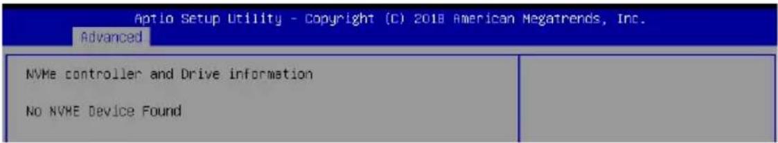
text_image
Aptio Setup Utility - Copyright (C) 2018 American Megatrends, Inc. Advanced NVMe controller and Drive information No NVME Device Found5.4.13 SATA Configuration
This page will display the SATA controller and drive information.

text_image
Aptio Setup Utility - Copyright (C) 2018 American Megatrends, Inc. Advanced SATA Configuration SATA Controller (S:00 B:42 D:00 F:02) ISATA1 PORT1 Not Present ISATA1 PORT2 Not Present ISATA1 PORT3 Not Present ISATA1 PORT4 Not Present ISATA2 PORT1 Not Present ISATA2 PORT2 Not Present ISATA2 PORT3 Not Present ISATA2 PORT4 Not Present SATA Controller (S:00 B:62 D:00 F:02) M.2SATA Not Present SATA1 Not Present SATA2 Not Present SATA8 Not Present SATA4 Not Present ++: Select Screen ↑↓: Select Item Enter: Select +/-: Change Opt. F1: General Help F2: Previous Values F5: Optimized Defaults F10: Save Changes & Reset F12: Print Screen ESC: Exit Version 2.18.1264. Copyright (C) 2018 American Megatrends, Inc.5.4.14 USB Configuration
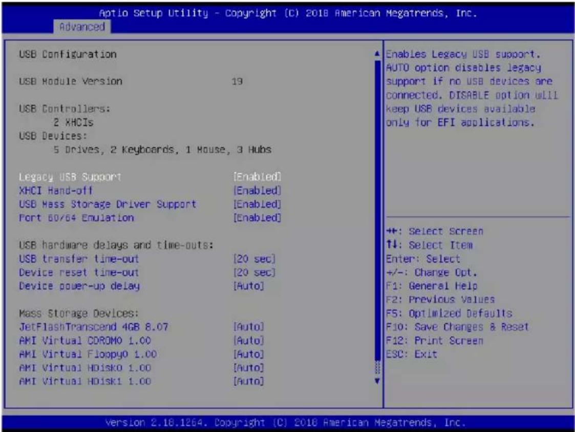
text_image
Aptio Setup Utility - Copyright (C) 2018 American Megatrends, Inc. Advanced USB Configuration USB Module Version 19 USB Controllers: 2 XHCIs USB Devices: 5 Drives, 2 Keyboards, 1 House, 3 Hubs Legacy USB Support [Enabled] XHCI Hand-off [Enabled] USB Mass Storage Driver Support [Enabled] Port 60/64 Emulation [Enabled] USB hardware delays and time-outs: USB transfer time-out [20 sec] Device reset time-out [20 sec] Device power-up delay [Auto] Mass Storage Devices: JetFlashTranscend 4GB 8.07 [Auto] AMI Virtual CDROMO 1.00 [Auto] AMI Virtual Floppy0 1.00 [Auto] AMI Virtual HDisk0 1.00 [Auto] AMI Virtual HDisk1 1.00 [Auto] Enables Legacy USB support. AUTO option disables legacy support if no USB devices are connected. DISABLE option will keep USB devices available only for EFI applications. ++: Select Screen ↑↓: Select Item Enter: Select +/-: Change Opt. F1: General Help F2: Previous Values F5: Optimized Defaults F10: Save Changes & Reset F12: Print Screen ESC: Exit version 2.18.1264. Copyright (C) 2018 American Megatrends, Inc.Legacy USB Support [Enabled]
Allows you to enable or disable Legacy USB device support.
Configuration options: [Enabled] [Disabled] [Auto]
XHCI Hand-off [Enabled]
Allows you to enable or disable workaround for OSes without XHCI hand-off support. The XHCI ownership change should be claimed by XHCI driver.
Configuration options: [Enabled] [Disabled]
USB Mass Storage Driver Support [Enabled]
Allows you to enable or disable the USB Mass Storage driver support.
Configuration options: [Disabled] [Enabled]
Port 60/64 Emulation [Enabled]
Allows you to enable or disable I/O port 60h/64h emulation support. This should be enabled for the complete keyboard legacy support for non-USB aware OSes.
Configuration options: [Disabled] [Enabled]
USB hardware delays and time-outs
USB transfer time-out [20 sec]
Allows you to select time-out value for Control, Bulk, and Interrupt transfers.
Configuration options: [1 sec] [5 sec] [10 sec] [20 sec]
Device reset time-out [20 sec]
Allows you to select time-out value for USB mass storage device Start Unit command.
Configuration options: [10 sec] [20 sec] [30 sec] [40 sec]
Device power-up delay [Auto]
Allows you to select maximum time the device will take before it properly reports itself to the Host Controller.
Configuration options: [Auto] [Manual]
Mass Storage Devices
AMI Virtual CDROM0-2 / Floppy / HDisk0 1.00 [Auto]
Allows you to select the mass storage device emulation type.
Configuration options: [Auto] [Floppy] [Forced FDD] [Hard Disk] [CD-ROM]
5.4.15 iSCSI Configuration
Allows you to configure the iSCSi parameters.

text_image
Aptio Setup Utility - Copyright (C) 2018 American Megatrends, Inc. Advanced iSCSI Initiator Name ► Add an Attempt ► Delete Attempts ► Change Attempt Order The worldwide unique name of iSCSI Initiator. Only IQN format is accepted. Range is from 4 to 2235.5 Chipset menu
The Chipset menu items allow you to change the Chipset settings.
| Aptio Setup Utility - Copyright (C) 2018 American Megatrends, Inc. | |
| Main Advanced Chipset Security Boot Tool Save & Exit AMD CBS Event Logs Server Ngmt | |
| SMT Mode [Auto] PCIe Link Training Type [1 Step] North Bridge | Simultaneous multithreading. OFF=1T single-thread Auto=2T two-thread If capable. |
SMT Mode [Auto]
Allows you to select the simultaneous multithreading mode.
Configuration options: [Auto] [Off]
PCIe Link Training Type [1 Step]
Allows you to select the PCIe training in 1 or 2 steps.
Configuration options: [1 Step] [2 Step]
North Bridge
Memory Configuration
Memory Clock [Auto]
This option allows you to select different memory clock values.
Configuration options: [Auto] [1333MHz] [1600MHz] [1866MHz] [2133MHz] [2400MHz]
Socket 0 Information
This item displays the memory information on Socket 0.
Socket 1 Information
This item displays the memory information on Socket 1.
5.6 Security menu
This menu allows a new password to be created or a current password to be changed. The menu also enables or disables the Secure Boot state and lets the user configure the System Mode state.
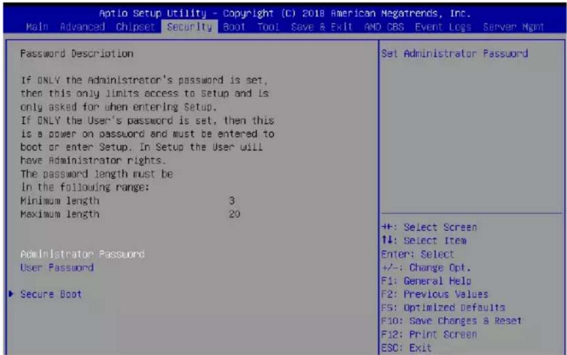
text_image
Aptio Setup Utility - Copyright (C) 2018 American Megatrends, Inc. Main Advanced Chipset Security Boot Tool Save & Exit AMD CBS Event Logs Server Mgmt Password Description If ONLY the Administrator's password is set, then this only limits access to Setup and is only asked for when entering Setup. If ONLY the User's password is set, then this is a power on password and must be entered to boot or enter Setup. In Setup the User will have Administrator rights. The password length must be in the following range: Minimum length 3 Maximum length 20 Administrator Password User Password Secure Boot Set Administrator Password +/-: Select Screen ↓: Select Item Enter: Select +/-: Change Opt. F1: General Help F2: Previous Values F5: Optimized Defaults F10: Save Changes & Reset F12: Print Screen ESC: ExitAdministrator Password
To set an administrator password:
- Select the Administrator Password item and press
. - From the Create New Password box, key in a password, then press
. - Confirm the password when prompted.
To change an administrator password:
- Select the Administrator Password item and press
. - From the Enter Current Password box, key in the current password, then press
. - From the Create New Password box, key in a new password, then press
. - Confirm the password when prompted.

To clear the administrator password, follow the same steps as in changing an administrator password, but press
User Password
To set a user password:
- Select the User Password item and press
. - From the Create New Password box, key in a password, then press
. - Confirm the password when prompted.
To change a user password:
- Select the User Password item and press
. - From the Enter Current Password box, key in the current password, then press
. - From the Create New Password box, key in a new password, then press
. - Confirm the password when prompted.
To clear a user password:
- Select the Clear User Password item and press
. - Select Yes from the Warning message window then press
.
Secure Boot
This item allows you to customize the Secure Boot settings.
| Aptio Setup Utility - Copyright (C) 2018 American Megatrends, Inc. Security | ||
| System Mode | Setup | Secure Boot activated when Platform Key(PK) is enrolled, System mode Is User/Deployed, and CSM function is disabled |
| Secure Boot | Not Active | |
| Vendor Keys | Active | |
| Attempt Secure Boot | [Disabled] | |
| Secure Boot Mode | [Custom] | |
| Key Management | ||
Attempt Secure Boot [Disabled]
Secure Boot can be enabled if the system is running in User mode with enrolled platform Key (EPK) or if the CSM function is disabled.
Configuration options: [Disabled] [Enabled]
Secure Boot Mode [Custom]
Allows you to set the Secure Boot selector. Configuration options: [Custom] [Standard]
Key Management
This item only appears when the item Secure Boot Mode is set to [Custom]. The Key Management item allows you to modify Secure Boot variables and set Key Management page.
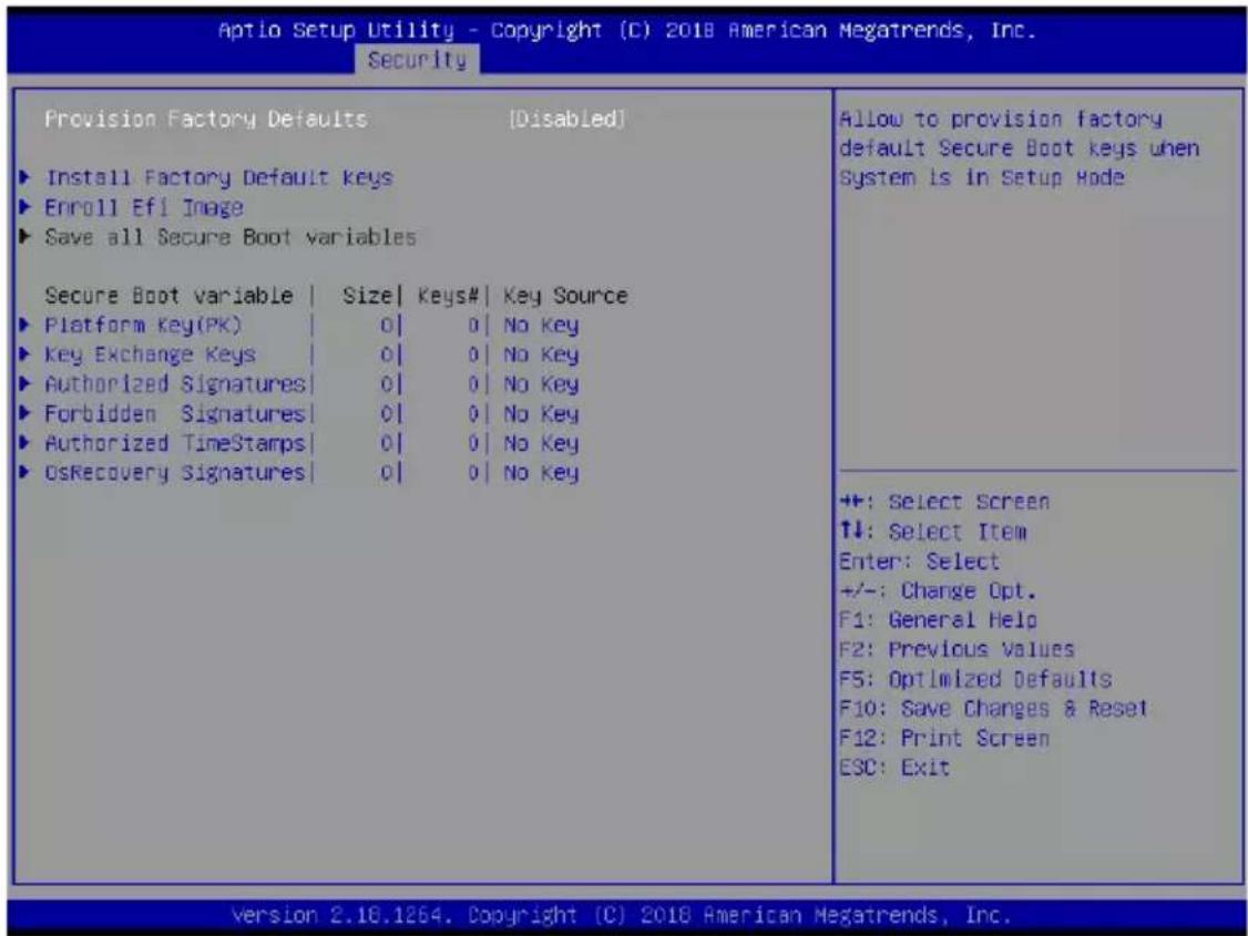
text_image
Aptio Setup Utility - Copyright (C) 2018 American Megatrends, Inc. Security Provision Factory Defaults [Disabled] ► Install Factory Default Keys ► Enroll Efi Image ► Save all Secure Boot variables Secure Boot variable | Size | Keys# | Key Source ► Platform Key(PK) | 0 | 0 | No Key ► Key Exchange Keys | 0 | 0 | No Key ► Authorized Signatures | 0 | 0 | No Key ► Forbidden Signatures | 0 | 0 | No Key ► Authorized TimeStamps | 0 | 0 | No Key ► OsRecovery Signatures | 0 | 0 | No Key Allow to provision factory default Secure Boot keys when System is in Setup Mode +:-: Select Screen ↑↓: Select Item Enter: Select +/-: Change Opt. F1: General Help F2: Previous Values F5: Optimized Defaults F10: Save Changes & Reset F12: Print Screen ESC: Exit version 2.16.1264. Copyright (C) 2018 American Megatrends, Inc.Provision Factory Defaults [Disabled]
Allows you to provision factory default Secure Boot keys when the system is in Setup Mode.
Configuration options: [Disabled] [Enabled]
Install Factory Default keys
This item will install all Factory Default keys.
Enroll Efi Image
This item will allow the image to run in Secure Boot mode.
Save All Secure Boot Variables
This item will ask you if you want to save all secure boot variables. Select Yes if you want to save all secure boot variables, otherwise select No.
Platform Key (PK) / Key Exchange Key (KEK) / Authorized Signatures (DB) / Forbidden Signatures (DBX) / Authorized TimeStamps (DBT) / OsRecovery Signatures
Configuration options: [Erase] [Set New] [Save to File]
5.7 Boot menu
The Boot menu items allow you to change the system boot options.
| Aptio Setup Utility - Copyright (C) 2018 American Megatrends, Inc. Main Advanced Chipset Security Boot Tool Save & Exit AND CBS Event Logs Server Mgmt | |
| Boot Configuration Setup Prompt Timeout Bootup NumLock State Boot Logo Display POST Report | 1 [On] [Disabled] [5 sec] |
| Chassis Intrusion Message | [Warning] |
| Boot Option Priorities Boot Option #1 | [AMI Virtual CDR0K0 1.00] |
| Boot Option #2 | [AMI Virtual HDisk0 1.00] |
| Boot Option #3 | [AMI Virtual Floppy0 1.00] |
| Boot Option #4 | [IBA GE Slot 2900 v1578] |
Setup Prompt Timeout [1]
Allows you to set the number of seconds to wait for setup activation key.
Bootup NumLock State [On]
Allows you to select the power-on state for the NumLock.
Configuration options: [Off] [On]
Boot Logo Display [Disabled]
Allows you to enable or disable the full screen logo display feature.
Configuration options: [Auto] [Full Screen] [Disabled]
POST Report [5 sec]
Allows you to set the desired POST Report waiting time from 1 to 10 seconds.
Configuration options: [1 sec] \~ [10 sec] [Until Press ESC]
Chassis Intrusion Message [Warning]
Allows you to select the action to perform when chassis intrusion has occurred.
Configuration options: [Warning] [Halt]
Boot Option Priorities
These items specify the boot device priority sequence from the available devices. The number of device items that appears on the screen depends on the number of devices installed in the system.

- To select the boot device during system startup, press
when ASUS Logo appears. - To access Windows OS in Safe Mode, please press
after POST.
Floppy Drive BBS Priorities / Hard Drive BBS Priorities / CD/DVD ROM Drive BBS Priorities
These items appear only when you connect Floppy / SATA ODD or HDD to the SATA ports and allow you to set the booting order of the SATA devices.
5.8 Tool menu
The Tool menu items allow you to configure options for special functions. Select an item then press

text_image
Aptio Setup Utility - Copyright (C) 2018 American Megatrends, Inc. Main Advanced Chipset Security Boot Tool Save & Exit AND CBS Event Logs Server Mgmt IPMI HKM Start EzFlash IPMI HKMIPMI HWM
Allows you to run the IPMI hardware monitor.
Start EZ Flash
Allows you to run ASUS EZ Flash BIOS ROM Utility when you press
5.9 Save & Exit menu
The Exit menu items allow you to save or discard your changes to the BIOS items.
| Aptio Setup Utility - Copyright (C) 2018 American Megatrends, Inc. Main Advanced Chipset Security Boot Tool Save & Exit AMD CBS Event Logs Server Mgmt | |
| Save Changes and Exit Discard Changes and Exit Save Changes and Reset Discard Changes and Reset Save Options Save Changes Discard Changes Restore Defaults Save as User Defaults Restore User Defaults Boot Override IBA GE Slot 2300 v1578 AMI Virtual CDROMO 1.00 AMI Virtual HDisk0 1.00 AMI Virtual HDisk1 1.00 AMI Virtual Floppy0 1.00 Launch EFI Shell from filesystem device | Exit system setup after saving the changes. +: Select Screen ↑↓: Select Item Enter: Select +/-: Change Opt. F1: General Help F2: Previous Values F5: Optimized Defaults F10: Save Changes & Reset F12: Print Screen ESC: Exit |
Save Changes and Exit
Exit system setup after saving the changes.
Discard Changes and Exit
Exit system setup without saving any changes.
Save Changes and Reset
Rest system setup after saving the changes.
Discard Changes and Rest
Rest system setup without saving any changes.
Save Changes
Save changes done so far to any of the setup options.
Discard Changes
Discard changes done so far to any of the setup options.
Restore Defaults
Restore/load default values for all the setup options.
Save as User Defaults
Save all the current setup options as user default values.
Restore as User Defaults
Restore/load user default values for all the setup options.
Boot Override
These items displays the available devices. The device items that appears on the screen depends on the number of devices installed in the system. Click an item to start booting from the selected device.
5.10 AMD CBS menu
The Exit menu items allow you to save or discard your changes to the BIOS items.
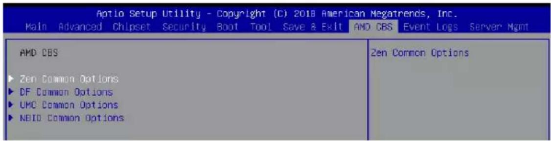
text_image
Aptio Setup Utility - Copyright (C) 2018 American Megatrends, Inc. Main Advanced Chipset Security Boot Tool Save & Exit AND CBS Event Logs Server Mgmt AMD CBS Zen Common Options DF Common Options UMC Common Options NBID Common Options Zen Common Options5.10.1 Zen Common Options
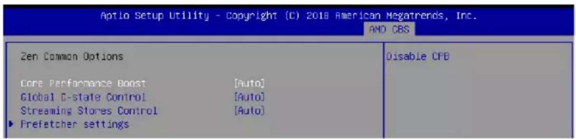
text_image
Aptio Setup Utility - Copyright (C) 2018 American Megatrends, Inc. AND CBS Zen Common Options Disable CPB Core Performance Boost [Auto] Global C-state Control [Auto] Streaming Stores Control [Auto] ▶ Prefetcher settingsCore Performance Boost [Auto]
This option allows you to enable or disable CPB.
Configuration options: [Disabled] [Auto]
Global C-state Control [Auto]
This option allows you to control IO based C-state generation and DF c-states.
Configuration options: [Disabled] [Enabled] [Auto]
Streaming Stores Control [Auto]
This option allows you to enable or disable the streaming stores functionality.
Configuration options: [Disabled] [Enabled] [Auto]
Prefetcher settings
L1 Stream HW Prefetcher [Auto]
This option allows you to enable or disable L1 Stream HW Prefetcher. Configuration options: [Disabled] [Enabled] [Auto]
L2 Stream HW Prefetcher [Auto]
This option allows you to enable or disable L2 Stream HW Prefetcher. Configuration options: [Disabled] [Enabled] [Auto]
5.10.2 DF Common Options
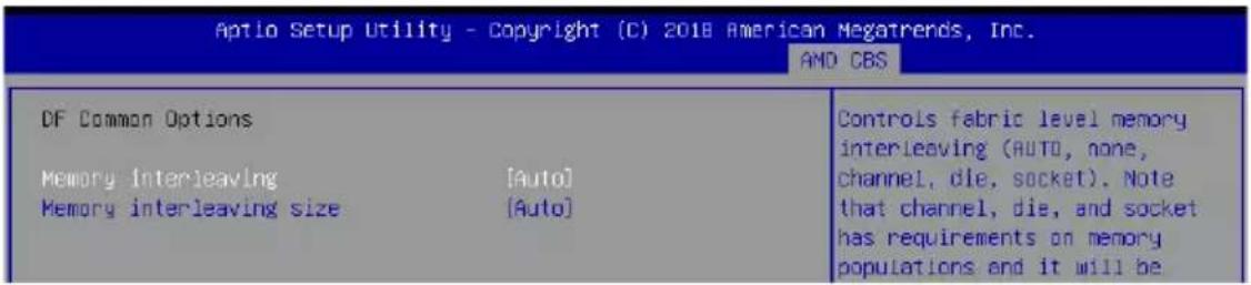
text_image
Aptio Setup Utility - Copyright (C) 2018 American Megatrends, Inc. AND CBS DF Common Options Memory interleaving [Auto] Memory interleaving size [Auto] Controls fabric level memory interleaving (AUTO, none, channel, die, socket). Note that channel, die, and socket has requirements on memory populations and it will beMemory interleaving [Auto]
This option allows you to control fabric level memory interleaving.
Configuration options: [None] [Channel] [Die] [Socket] [Auto]
Memory interleaving size [Auto]
This option allows you to control the memory interleaving size.
Configuration options: [256 Bytes] [512 Bytes] [1 KB] [2 KB] [Auto]
5.10.3 UMC Common Option

text_image
Aptio Setup Utility - Copyright (C) 2018 American Megatrends, Inc. AND CBS UMC Common Options DDR4 Common Options DRAH Memory Mapping DDR4 Common OptionsDDR4 Common Options
DRAM Timing Configuration
This option allows you to set memory overclock settings. Read the disclaimer and select I Accept to continue.
DRAM Controller Configuration
Power Down Options
Power Down Enable [Auto]
This option allows you to enable or disable DDR power down mode.
Configuration options: [Disabled] [Enabled] [Auto]
Cmd2T [Auto]
This option allows you to select between 1T and 2T mode on ADDR/CMD.
Configuration options: [1T] [2T] [Auto]
Gear Down Mode [Auto]
This option allows you to select the Gear Down Mode.
Configuration options: [Disabled] [Enabled] [Auto]
Data Bus Configuration
Data Bus Configuration User Controls [Auto]
This option allows you to interleave memory blocks across DRAM chip selects for node 0.
Configuration options: [Auto] [Manual]
![ASUS RS500A-E9-PS4 - Data Bus Configuration User Controls [Auto] - 1](/content/2026/06/1202776/images/005a1c37d2f24f46f471f5046a3d12c0cb87e3c4ef31c93c774077dc5c61b42f.jpg)
The following item appears only when Data Bus Configuration User Controls is set to [Manual].
RttNom [Auto]
Configuration options: [Rtt_Nom Disable] [RZQ/4] [RZQ/2] [RZQ/6] [RZQ/1] [RZQ/5] [RZQ/3] [RZQ/7] [Auto]
RttWr [Auto]
Configuration options: [Dynamic ODT Off] [RZQ/2] [RZQ/1] [Hi-Z] [RZQ/3] [Auto]
RttPark [Auto]
Configuration options: [Rtt_PARK Disable] [RZQ/4] [RZQ/2] [RZQ/6] [RZQ/1] [RZQ/5] [RZQ/3] [RZQ/7] [Auto]
Common RAS
Data Poisoning [Auto]
This option allows you to enable or disable Data Poisoning.
Configuration options: [Disabled] [Enabled] [Auto]
ECC Configuration
DRAM ECC Symbol Size [Auto]
This option allows you to set the DRAM ECC Symbol Size.
Configuration options: [Auto] [x4] [x8]
DRAM ECC Enable [Auto]
This option allows you to enable or disable DRAM ECC.
Configuration options: [Disabled] [Enabled] [Auto]
DRAM Memory Mapping
Chipselect Interleaving [Auto]
This option allows you to interleave memory blocks across DRAM chip selects for node 0.
Configuration options: [Disabled] [Auto]
BankGroupSwap [Auto]
This option allows you to enable or disable BankGroupSwap.
Configuration options: [Disabled] [Enabled] [Auto]
5.10.4 NBIO Common Options

text_image
Aptlo Setup Utility - Copyright (C) 2018 American Megatrends, Inc. AMD CBS NBIO Common Options ► NB Configuration NBIO Internal Polson Consumption [Auto] NBIO RAS Control [Auto] cTDP Control [Manual] cTDP 200 Efficiency Optimized Mode [Auto] ACS Enable [Auto] PCIe ARI Support [Auto] CLDO_VDDP Control [Auto] HD Audio Enable [Auto] Block PCIe Loopback [Auto] CRS Delay 6 CRS Limit 6 ► Hot Plug flags No help string +: Select Screen ↑↓: Select Item Enter: Select +/-: Change Opt. 5% General needsNB Configuration
IOMMU [Enabled]
This option allows you to enable or disable IOMMU.
Configuration options: [Disabled] [Enabled] [Auto]
Concurrent Training [Auto]
This option allows you to enable or disable Concurrent Training.
Configuration options: [False] [True] [Auto]
NBIO Internal Poison Consumption [Auto]
This option allows you to enable or disable NBIO Internal Poison Consumption.
Configuration options: [Disabled] [Enabled] [Auto]
NBIO RAS Control [Auto]
This option allows you to enable or disable NBIO RAS Control.
Configuration options: [Disabled] [Enabled] [Auto]
cTDP Control [Manual]
This option allows you to set the cTDP.
Configuration options: [Manual] [Auto]
![ASUS RS500A-E9-PS4 - cTDP Control [Manual] - 1](/content/2026/06/1202776/images/3a24aae003833c1d0a7118b1513a6e50ebb5b3f4e3b95776e2e0a871688bb648.jpg)
The following item appears only when cTDP Control is set to [Manual].
cTDP [200]
This option allows you to set the cTDP value.
Efficiency Optimized Mode [Auto]
This option allows you to enable or disable Efficiency Optimized Mode.
Configuration options: [Disabled] [Enabled] [Auto]
ACS Enable [Auto]
This option allows you to enable or disable ACS.
Configuration options: [Disabled] [Enabled] [Auto]
PCIe ARI Support [Auto]
This option allows you to enable or disable PCIe ARI Support.
Configuration options: [Disabled] [Enabled] [Auto]
CLDO\_VDDP Control [Auto]
This option allows you to set the CLDO_VDDP.
Configuration options: [Manual] [Auto]
![ASUS RS500A-E9-PS4 - CLDO\_VDDP Control [Auto] - 1](/content/2026/06/1202776/images/275b69a6a3e8612e80466dbc7bcce4bdcd869af2dc0ff5fd682ad054cce72af0.jpg)
The following item appears only when CLDO_VDDP Control is set to [Manual].
CLDO\_VDDP voltage [0]
This option allows you to set the CLDO_VDDP voltage.
HD Audio Enable [Auto]
This option allows you to enable or disable HD Audio.
Configuration options: [Disabled] [Enabled] [Auto]
Block PCIe Loopback [Auto]
This option allows you to enable or disable Block PCIe Loopback mode for hot plug slots.
Configuration options: [Disabled] [Enabled] [Auto]
CRS Delay [6]
This option allows you to set the CRS Delay.
CRS Limit [6]
This option allows you to set the CRS Limit.
Hot Plug flags
Ignore sideband [Disabled]
This option allows you to enable or disable sideband.
Configuration options: [Disabled] [Enabled] [Auto]
Disable L1 w/a [Disabled]
This option allows you to enable or disable L1 w/a.
Configuration options: [Disabled] [Enabled] [Auto]
Disable BridgeDis [Disabled]
This option allows you to enable or disable BridgeDis update based on sideband.
Configuration options: [Disabled] [Enabled] [Auto]
Disable irq polling [Disabled]
This option allows you to enable or disable irq polling.
Configuration options: [Disabled] [Enabled] [Auto]
IRQ sets BridgeDis [Disabled]
This option allows you to enable or disable IRQ sets BridgeDis.
Configuration options: [Disabled] [Enabled] [Auto]
5.11 Event Logs menu
The Event Logs menu items allow you to change the event log settings and view the system event logs.

text_image
Aptio Setup Utility - Copyright (C) 2018 American Megatrends, Inc. Main Advanced Chipset Security Boot Tool Save & Exit AND CBS Event Logs Server Mgmt Change SMBios Event Log Settings View SMBios Event Log Press5.11.1 Change Smbios Event Log Settings
Press

All values changed here do not take effect until computer is restarted.
Enabling/Disabling Options
Smbios Event Log [Enabled]
Change this to enable or disable all features of Smbios Event Logging during boot.
Configuration options: [Disabled] [Enabled]
Erasing Settings
Erase Event Log [No]
Choose options for erasing Smbios Event Log. Erasing is done prior to any logging activation during reset.
Configuration options: [No] [Yes, Next reset] [Yes, Every reset]
When Log is Full [Do Nothing]
Choose options for reacting to a full Smbios Event Log.
Configuration options: [Do Nothing] [Erase Immediately]
Smbios Event Log Standard Settings
Log System Boot Event [Disabled]
This option allows you to enable or disable logging System boot event.
Configuration options: [Disabled] [Enabled]
5.11.2 View Smbios Event Log
Press
5.12 Server Mgmt menu
The Server Management menu displays the server management status and allows you to change the settings.

text_image
Aptio Setup Utility - Copyright (C) 2018 American Megatrends, Inc. Main Advanced Chipset Security Boot Tool Save & Exit AND CBS Event Logs Server Mgmt EMC Self Test Status PASSED EMC Device ID 32 EMC Device Revision 1 EMC Firmware Revision 1.12 IPMI Version 2.0 Current Time Zone +08:00 GMT OS Watchdog Timer [Disabled] OS Htd Timer Timeout [10 minutes] OS Htd Timer Policy [Reset] ► System Event Log ► EMC network configuration ► View System Event Log If enabled, starts a BIOS timer which can only be shut off by Management Software after the OS loads. Helps determine that the OS successfully loaded or follows the OS Boot Watchdog Timer policy. +It: Select ScreenOS Watchdog Timer [Disabled]
This item allows you to start a BIOS timer which can only be shut off by Intel Management Software after the OS loads.
Configuration options: [Disabled] [Enabled]
![ASUS RS500A-E9-PS4 - OS Watchdog Timer [Disabled] - 1](/content/2026/06/1202776/images/0adb62b2e7fd687238ea8daa7194dd8d376e0b279cea6e0d96b8bce1692d8964.jpg)
The following items is configurable only when the OS Watchdog Timer is set to [Enabled].
OS Wtd Timer Timeout [10 minutes]
Allows you to configure the length fo the OS Boot Watchdog Timer.
Configuration options: [5 minutes] [10 minutes] [15 minutes] [20 minutes]
OS Wtd Timer Policy [Reset]
This item allows you to configure the how the system should respond if the OS Boot Watch Timer expires.
Configuration options: [Do Nothing] [Reset] [Power Down]
System Event Log
Allows you to change the SEL event log configuration.
SEL Components [Enabled]
This option allows you to enable or disable SEL Components.
Configuration options: [Disabled] [Enabled]
![ASUS RS500A-E9-PS4 - SEL Components [Enabled] - 1](/content/2026/06/1202776/images/3c3b6193f4c327b2735231429316d4d183626a1c358d689aae2d4d7d15c65e86.jpg)
The following items is configurable only when the SEL Components is set to [Enabled].
Erase SEL [No]
Allows you to choose options for erasing SEL.
Configuration options: [No] [Yes, On next reset] [Yes, On every reset]
When SEL is Full [Do Nothing]
Allows you to choose options for reactions to a full SEL.
Configuration options: [Do Nothing] [Erase Immediately]
BMC network configuration
The sub-items in this configuration allow you to configure the BMC network parameters.
View System Event Log
This item allows you to view the system event log records.
Driver Installation
This chapter provides the instructions for installing the necessary drivers for different system components in the Windows ^® Operating System.

6.1 Management applications and utilities installation
The support DVD that is bundled with your motherboard contains drivers, management applications, and utilities that you can install to maximize the features of your motherboard.

- The contents of the support DVD are subject to change at any time without notice. Visit the ASUS website (www.asus.com) for the latest updates on software and utilities.
- The support DVD is supported on Windows ^® Server 2012 R2 and Windows ^® Server 2016.
6.2 Running the Support DVD
When you place the support DVD into the optical drive, the DVD automatically displays the main screen if Autorun is enabled in your computer. By default, the Drivers tab is displayed.

If Autorun is NOT enabled in your computer, browse the contents of the support DVD to locate the file ASSETUP.EXE from the BIN folder. Double-click the ASSETUP.EXE to run the support DVD.
The main screen of the Support DVD contains the following tabs:
- Drivers
- Utilities
- Manual
- Contact

The main screen of the Support DVD looks exactly the same on the Windows ^® Server 2012 R2 and on the Windows ^® Server 2016 Operating System (OS).
6.2.1 Drivers menu tab
The Drivers Menu shows the available device drivers if the system detects installed devices. Install the necessary drivers to activate the devices.
text_image
SP3 Sapios FNPP-D32 Series Support DVD - Windows Service 2012 F264.bj Drivers AMD Software Intel(R) I350-AM2 Gigabit Adapters Driver ASPEED AST2500 Display Driver MB Please select items to install.6.2.2 Utilities menu tab
The Utilities menu displays the software applications and utilities that the motherboard supports.
text_image
SF3 Series FNPP D32 Series Support DVD - Windows Service 2012: R284 bit Options Office Manual Contact ASUS Install ASUS Update MB Please select items to install.6.2.3 Manual menu
The Manual menu provides the link to the Broadcom NetXtreme II Network Adapter user guide.

You need an internet browser installed in your OS to view the User Guide.
text_image
Z11PP-D24 Series User Guide Z10PR-D16 User Guide Z10PA-D8 Series User Guide RS500-E8 Series User Guide Please select items to install6.2.4 Contact information menu
The Contact menu displays the ASUS contact information, e-mail addresses, and useful links if you need more information or technical support for your motherboard.
text_image
SP3 Sanos UIPP D3S Series Support DVD - Windows Service 2012 R2.84 bit Address: 15 Li-Te Road, Paltori, Taipei, Taiwan 11259 Telephone: +886-2-2894-3447 Fax: +886-2-2690-7790 Email: info@asus.com Web site: http://www.asus.com Technical Support Telephone: +88-21-38429911 FAX: +88-21-5866722, ext. 9101# Online Support: http://support.asus.com/tech/serv.aspx ASUSTeK COMPUTER INC (Taiwan) ASUSTeK COMPUTER INC (China) ASUS COMPUTER INTERNATIONAL (America) ASUS COMPUTER GmbH (Germany & Austria)6.3 AMD chipset device software installation
This section provides the instructions on how to install the AMD chipset device software on the system.
You need to manually install the AMD chipset device software on a Windows operating system.
To install the AMD chipset device software:
-
Restart the computer, and then log on with Administrator privileges.
-
Insert the motherboard/system support DVD into the optical drive. The support DVD automatically displays the Drivers menu if Autorun is enabled in your computer.

If Autorun is NOT enabled in your computer, browse the contents of the support DVD to locate the file ASSETUP.EXE from the BIN folder. Double-click the ASSETUP.EXE to run the support DVD.
- Click the item AMD Software from the menu.
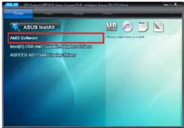
text_image
SP35 software /MPD-032 Series Support DVD - Windows Server 2012/07/04 Drivers Options Help Correct ASUS InstAll AMD Software Intel(R) I350-AM2 Gigabe?Adapters Driver ASPEED AST2S80 Display Driver Please select items to install- The AMD Software window appears. Click Accept and Install to start the installation, and follow the onscreen instructions to complete the setup process.
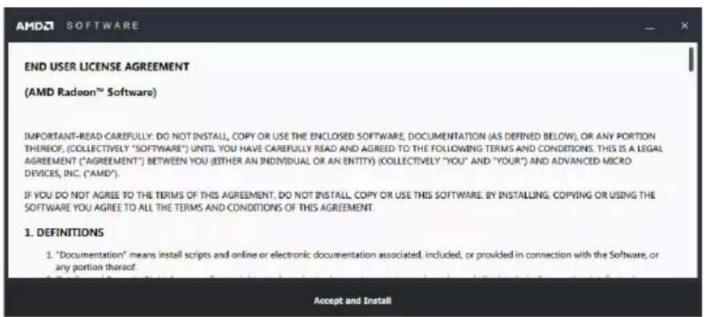
text_image
AMD END USER LICENSE AGREEMENT (AMD Radeon™ Software) IMPORTANT-READ CAREFULLY: DO NOT INSTALL, COPY OR USE THE ENCLOSED SOFTWARE, DOCUMENTATION (AS DEFINED BELOW), OR ANY PORTION THEREOF, (COLLECTIVELY "SOFTWARE") UNTIL YOU HAVE CAREFULLY READ AND AGREED TO THE FOLLOWING TERMS AND CONDITIONS. THIS IS A LEGAL AGREEMENT ("AGREEMENT") BETWEEN YOU (EITHER AN INDIVIDUAL OR AN ENTITY) (COLLECTIVELY "YOU" AND "YOUR") AND ADVANCED MICRO DEVICES, INC. ("AMD"). IF YOU DO NOT AGREE TO THE TERMS OF THIS AGREEMENT, DO NOT INSTALL COPY OR USE THIS SOFTWARE BY INSTALLING, COPYING OR USING THE SOFTWARE YOU AGREE TO ALL THE TERMS AND CONDITIONS OF THIS AGREEMENT. 1. DEFINITIONS 1. "Documentation" means install scripts and online or electronic documentation associated, included, or provided in connection with the Software, or any portion thereof.6.4 Installing the Intel driver ^® I350-AM2 Gigabit Adapters
This section provides the instructions on how to install the Intel ^® I350-AM2 Gigabits Adapter Driver on the system.
To install the Intel ^® I350-AM2 Gigabit Adapters Driver on the Windows ^® operating system:
- Restart the computer.
- Log on with Administrator privileges.
- Insert the motherboard/system support DVD to the optical drive.

If Autorun is NOT enabled in your computer, browse the contents of the support DVD to locate the file ASSETUP.EXE from the BIN folder. Double-click the ASSETUP.EXE to run the support DVD.
- Click Intel ^® I350-AM2 Gigabit Adapters Drivers in the Drivers menu of the main screen to start the installation.
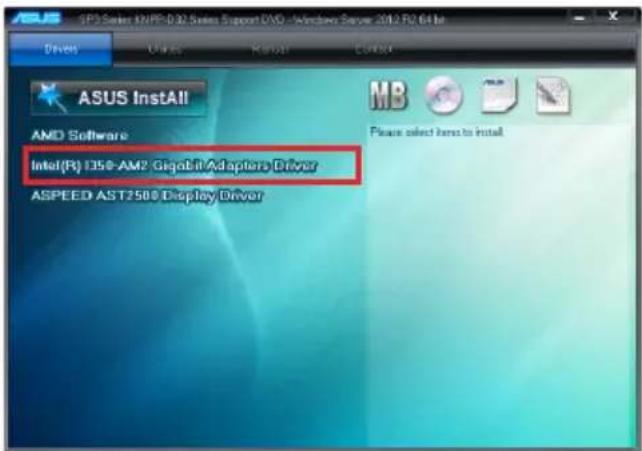
text_image
SPS Series AMD-0.32 Series Support DVD - Windows Server 2012 R2.64 Bar Drives Units Kuwait Control ASUS InstAll AMD Software Intel(R) 1350-AM2 Gigobit Adapters Driver ASPEED AST2500 Display Driver Please select home to install- Click Install Drivers and Software option to begin installation.

text_image
Intel® Network Connections Intel Network Connections Install Drivers and Software View User Guides View Release Notes Networking at Intel.com Version: 22.1.104.06. Click Install to start the installation.
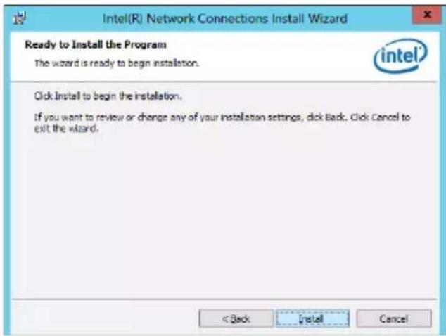
text_image
Intel(R) Network Connections Install Wizard Ready to Install the Program The wizard is ready to begin installation. intel Click Install to begin the installation. If you want to review or change any of your installation settings, click Back. Click Cancel to exit the wizard. < Back Install Cancel7. When the installation is done, press Finish to complete the installation.
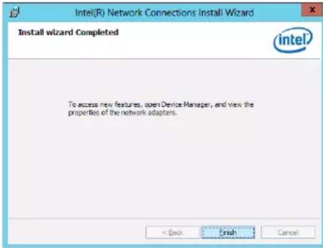
text_image
Intel(R) Network Connections Install Wizard Install wizard Completed intel To access new features, open Device Manager, and view the properties of the network adapters. < Back Finish Cancel6.5 VGA driver installation
This section provides the instructions on how to install the ASPEED Video Graphics Adapter (VGA) driver.
You need to manually install the ASPEED VGA driver on a Windows ^® operating system.
To install the ASPEED VGA driver:
- Restart the computer, and then log on with Administrator privileges.
- Insert the motherboard/system support DVD into the optical drive. The support DVD automatically displays the Drivers menu if Autorun is enabled in your computer.

If Autorun is NOT enabled in your computer, browse the contents of the support DVD to locate the file ASSETUP.EXE from the BIN folder. Double-click the ASSETUP.EXE to run the support DVD.
- Click the ASPEED AST2500 Display Driver to begin installation.
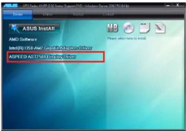
text_image
ASUS InstAll AMD Software Intel(R) 135®-AM2 Gigabit/Adapters Driver ASPEED AST2.50 Display Driver- From the installation window, click Next to start the installation.
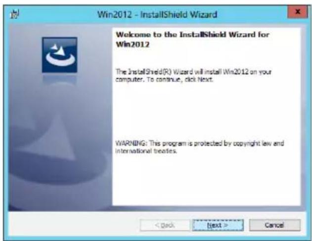
text_image
Win2012 - InstallShield Wizard Welcome to the InstallShield Wizard for Win2012 The InstallShield(R) Wizard will install Win2012 on your computer. To continue, click Next. WARNING: This program is protected by copyright law and international treaties.- Click Install to start the installation process.
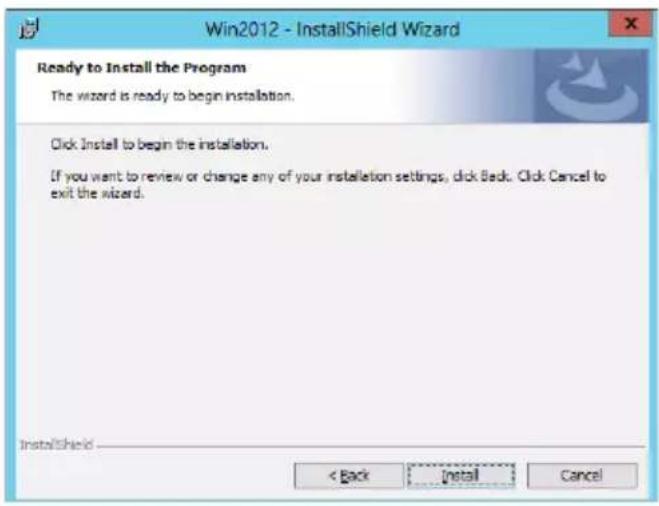
text_image
Win2012 - InstallShield Wizard Ready to Install the Program The wizard is ready to begin installation. Click Install to begin the installation. If you want to review or change any of your installation settings, click Back. Click Cancel to exit the wizard. InstallShield < Back Install Cancel- Click Finish to complete the installation.
text_image
Win2012 - InstallShield Wizard InstallShield Wizard Completed The InstallShield Wizard has successfully installed Win2012. Click Finish to exit the wizard.Appendix
KNPA-U16 block diagram
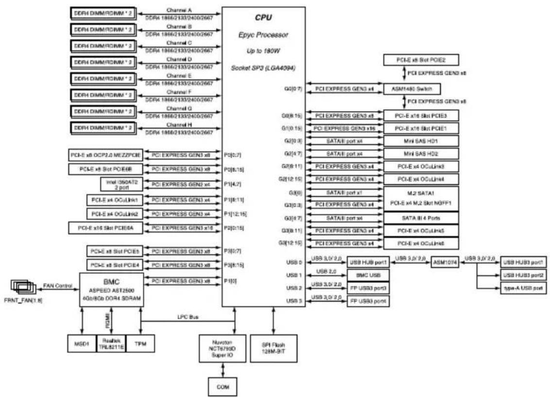
flowchart
Epyc processor architecture diagram showing connections between CPU, BMC ASPEED AST2500 4Gb/8Gb DDR4 SDRAM, and various peripheral ports and channels.Q-Code table
| Code Description | |
| 00 | Not used |
| 02 | microcode |
| 03 | CACHE_ENABLED |
| 04 | PCH initialization |
| 06 | CPU_EARLY_INIT |
| 10 | PEI Core is started |
| 11 – 14 | Pre-memory CPU initialization is started |
| 15 – 18 | Pre-memory System Agent initialization is started |
| 19 – 1C | Pre-memory PCH initialization is started |
| 2B – 2F | Memory initialization |
| 30 | Reserved for ASL (see ASL Status Codes section below) |
| 31 | Memory Installed |
| 32 – 36 | CPU post-memory initialization |
| 37 – 3A | Post-Memory System Agent initialization is started |
| 3B – 3E | Post-Memory PCH initialization is started |
| 4F | DXE IPL is started |
| 50 – 53 | Memory initialization error. Invalid memory type or incompatible memory speed |
| 4F | DXE IPL is started |
| 54 | Unspecified memory initialization error |
| 55 | Memory not installed |
| 56 | Invalid CPU type or Speed |
| 57 | CPU mismatch |
| 58 | CPU self test failed or possible CPU cache error |
| 59 | CPU micro-code is not found or micro-code update is failed |
| 5A | Internal CPU error |
| 5B | Reset PPI is not available |
| 5C – 5F | Reserved for future AMI error codes |
| E0 | S3 Resume is stared (S3 Resume PPI is called by the DXE IPL) |
| E1 | S3 Boot Script execution |
| E2 | Video repost |
| E3 | OS S3 wake vector call |
| E4 – E7 | Reserved for future AMI progress codes |
| E8 | S3 Resume Failed |
| E9 | S3 Resume PPI not Found |
| EA | S3 Resume Boot Script Error |
| EB | S3 OS Wake Error |
| EC – EF | Reserved for future AMI error codes |
| F0 | Recovery condition triggered by firmware (Auto recovery) |
| F1 | Recovery condition triggered by user (Forced recovery) |
| F2 | Recovery process started |
| F3 | Recovery firmware image is found |
| F4 | Recovery firmware image is loaded |
| F5 – F7 | Reserved for future AMI progress codes |
| F8 | Recovery PPI is not available |
| F9 | Recovery capsule is not found |
(continued on the next page)
| Code Description | |
| FA | Invalid recovery capsule |
| FB - FF | Reserved for future AMI error codes |
| 60 | DXE Core is started |
| 61 | NVRAM initialization |
| 62 | Installation of the PCH Runtime Services |
| 63 – 67 | CPU DXE initialization is started |
| 68 | PCI host bridge initialization |
| 69 | System Agent DXE initialization is started |
| 6A | System Agent DXE SMM initialization is started |
| 6B – 6F | System Agent DXE initialization (System Agent module specific) |
| 70 | PCH DXE initialization is started |
| 71 | PCH DXE SMM initialization is started |
| 72 | PCH devices initialization |
| 73 – 77 | PCH DXE Initialization (PCH module specific) |
| 78 | ACPI module initialization |
| 79 | CSM initialization |
| 7A – 7F | Reserved for future AMI DXE codes |
| 90 | Boot Device Selection (BDS) phase is started |
| 91 | Driver connecting is started |
| 92 | PCI Bus initialization is started |
| 93 | PCI Bus Hot Plug Controller Initialization |
| 94 | PCI Bus Enumeration |
| 95 | PCI Bus Request Resources |
| 96 | PCI Bus Assign Resources |
| 97 | Console Output devices connect |
| 98 | Console input devices connect |
| 99 | Super IO Initialization |
| 9A | USB initialization is started |
| 9B | USB Reset |
| 9C | USB Detect |
| 9D | USB Enable |
| 9E – 9F | Reserved for future AMI codes |
| A0 | IDE initialization is started |
| A1 | IDE Reset |
| A2 | IDE Detect |
| A3 | IDE Enable |
| A4 | SCSI initialization is started |
| A5 | SCSI Reset |
| A6 | SCSI Detect |
| A7 | SCSI Enable |
| A8 | Setup Verifying Password |
| A9 | Start of Setup |
| AA | Reserved for ASL (see ASL Status Codes section below) |
| AB | Setup Input Wait |
(continued on the next page)
| Code Description | |
| AC | Reserved for ASL (see ASL Status Codes section below) |
| AD | Ready To Boot event |
| AE | Legacy Boot event |
| AF | Exit Boot Services event |
| B0 | Runtime Set Virtual Address MAP Begin |
| B1 | Runtime Set Virtual Address MAP End |
| B2 | Legacy Option ROM Initialization |
| B3 | System Reset |
| B4 | USB hot plug |
| B5 | PCI bus hot plug |
| B6 | Clean-up of NVRAM |
| B7 | Configuration Reset (reset of NVRAM settings) |
| B8-BF | Reserved for future AMI codes |
| D0 | CPU initialization error |
| D1 | System Agent initialization error |
| D2 | PCH initialization error |
| D3 | Some of the Architectural Protocols are not available |
| D4 | PCI resource allocation error. Out of Resources |
| D5 | No Space for Legacy Option ROM |
| D6 | No Console Output Devices are found |
| D7 | No Console Input Devices are found |
| D8 | Invalid password |
| D9 | Error loading Boot Option (LoadImage returned error) |
| DA | Boot Option is failed (StartImage returned error) |
| DB | Flash update is failed |
| DC | Reset protocol is not available |
ACPI/ASL Checkpoints (under OS)
| Code Description | |
| 03 System | is entering S3 sleep state |
| 04 System | is entering S4 sleep state |
| 05 System | is entering S5 sleep state |
| 30 System | is waking up from the S3 sleep state |
| 40 System | is waking up from the S4 sleep state |
| AC System | has transitioned into ACPI mode. Interrupt controller is in PIC mode. |
| AA System | has transitioned into ACPI mode. Interrupt controller is in APIC mode. |
Notices
Federal Communications Commission Statement
This device complies with Part 15 of the FCC Rules. Operation is subject to the following two conditions:
- This device may not cause harmful interference, and
- This device must accept any interference received including interference that may cause undesired operation.
This equipment has been tested and found to comply with the limits for a Class A digital device, pursuant to part 15 of the FCC Rules. These limits are designed to provide reasonable protection against harmful interference when the equipment is operated in a commercial environment. This equipment generates, uses, and can radiate radio frequency energy and, if not installed and used in accordance with the instruction manual, may cause harmful interference to radio communications. Operation of this equipment in a residential area is likely to cause harmful interference in which case the user will be required to correct the interference at his own expense.

The use of shielded cables for connection of the monitor to the graphics card is required to assure compliance with FCC regulations. Changes or modifications to this unit not expressly approved by the party responsible for compliance could void the user's authority to operate this equipment.
Compliance Statement of Innovation, Science and Economic Development Canada (ISED)
This device complies with Innovation, Science and Economic Development Canada licence exempt RSS standard(s). Operation is subject to the following two conditions: (1) this device may not cause interference, and (2) this device must accept any interference, including interference that may cause undesired operation of the device.
CAN ICES-3(A)/NMB-3(A)
Complying with the REACH (Registration, Evaluation, Authorization, and Restriction of Chemicals) regulatory framework, we published the chemical substances in our products at ASUS website at http://csr.asus.com/english/REACH.htm.
ASUS Recycling/Takeback Services
ASUS recycling and takeback programs come from our commitment to the highest standards for protecting our environment. We believe in providing solutions for you to be able to responsibly recycle our products, batteries, other components as well as the packaging materials. Please go to http://csr.asus.com/english/Takeback.htm for detailed recycling information in different regions.

DO NOT throw the motherboard in municipal waste. This product has been designed to enable proper reuse of parts and recycling. This symbol of the crossed out wheeled bin indicates that the product (electrical and electronic equipment) should not be placed in municipal waste. Check local regulations for disposal of electronic products.

DO NOT throw the mercury-containing button cell battery in municipal waste. This symbol of the crossed out wheeled bin indicates that the battery should not be placed in municipal waste.
Australia statement notice
From 1 January 2012 updated warranties apply to all ASUS products, consistent with the Australian Consumer Law. For the latest product warranty details please visit https://www.asus.com/support/. Our goods come with guarantees that cannot be excluded under the Australian Consumer Law. You are entitled to a replacement or refund for a major failure and compensation for any other reasonably foreseeable loss or damage. You are also entitled to have the goods repaired or replaced if the goods fail to be of acceptable quality and the failure does not amount to a major failure.
If you require assistance please call ASUS Customer Service 1300 2787 88 or visit us at https://www.asus.com/support/.
ASUS contact information
ASUSTeK COMPUTER INC.
Address 4F, No. 150, Li-Te Rd., Peitou, Taipei 112, Taiwan
Telephone +886-2-2894-3447
Fax +886-2-2890-7798
Web site https://www.asus.com
Technical Support
Telephone +86-21-38429911
Fax +86-21-58668722 ext: 9101
Online Support https://www.asus.com/support/Product/ContactUs/Services/
questionform/?lang=en
ASUSTeK COMPUTER INC. (Taiwan)
Address 4F, No. 150, Li-Te Rd., Peitou, Taipei 112, Taiwan
Telephone +886-2-2894-3447
Fax +886-2-2890-7798
Web site https://www.asus.com/tw/
Technical Support
Telephone +886-2-2894-3447 (0800-093-456)
Online Support https://www.asus.com/support/Product/ContactUs/Services/
questionform/?lang=zh-tw
ASUSTeK COMPUTER INC. (China)
Address No. 5077, Jindu Road, Minhang District, Shanghai, China
Telephone +86-21-5442-1616
Fax +86-21-5442-0099
Web site https://www.asus.com.cn
Technical Support
Telephone +86-20-2804-7506 (400-620-6655)
Online Support https://www.asus.com/support/Product/ContactUs/Services/
questionform/?lang=zh-cn
ASUS contact information
ASUS COMPUTER INTERNATIONAL (America)
Address
48720 Kato Rd., Fremont, CA 94538, USA
Fax +1-510-608-4555
Web site https://www.asus.com/us/
Technical Support
Support fax +1-812-284-0883
General support +1-812-282-2787
Online support https://www.asus.com/support/Product/ContactUs/Services/
questionform/?lang=en-us
ASUS COMPUTER GmbH (Germany and Austria)
Address Harkort Str. 21-23, 40880 Ratingen, Germany
Fax +49-2102-959911
Web site https://www.asus.com/de/
Technical Support
Telephone +49-1805-010923
Support Fax +49-2102-959911
Online support https://www.asus.com/support/Product/ContactUs/Services/
questionform/?lang=de-de
ASUS Czech Service s.r.o. (Europe)
Address Na Rovince 887, 720 00 Ostrava – Hrabová,
Czech Republic
Telephone +420-596766888
Web site https://www.asus.com/cz/
Technical Support
Telephone +420-596-766-891
Fax +420-596-766-329
E-mail advance.rma.eu@asus.com
Online Support https://www.asus.com/support/Product/ContactUs/Services/
questionform/?lang=cs-cz
ASUS contact information
ASUS Holland BV (The Netherlands)
Address Marconistraat 2, 7825GD EMMEN, The Netherlands
Web site https://www.asus.com/nl/
Technical Support
Telephone +31-(0)591-5-70292
Fax +31-(0)591-666853
E-mail advance.rma.eu@asus.com
Online Support https://www.asus.com/support/Product/ContactUs/Services/
questionform/?lang=nl-nl
ASUS Polska Sp. z o.o. (Poland)
Online Support https://www.asus.com/support/Product/ContactUs/Services/
questionform/?lang=pl-pl
ASK-Service (Russia and CIS)
Online Support https://www.asus.com/support/Product/ContactUs/Services/
questionform/?lang=ru-ru