LHD720i - Video projector Christie - Free user manual and instructions
Find the device manual for free LHD720i Christie in PDF.

User questions about LHD720i Christie
0 question about this device. Answer the ones you know or ask your own.
Ask a new question about this device
Download the instructions for your Video projector in PDF format for free! Find your manual LHD720i - Christie and take your electronic device back in hand. On this page are published all the documents necessary for the use of your device. LHD720i by Christie.
USER MANUAL LHD720i Christie
User's Manual (detailed) Operating Guide
020-001279-01
LWU720i/LHD720i/LWU620i
CHKISTIE®
Projector
LWU720i/LHD720i/LWU620i
User's Manual (detailed) Operating Guide

natural_image
Line drawing of a projector with a circular vent and mesh chamber (no text or symbols)Thank you for purchasing this projector.
⚠ WARNING ▶ Before using this projector, read all the manuals for this projector. Read Safety Guide first. After reading the manuals, store them in a safe place for future reference.
About this manual
Various symbols are used in this manual. The meanings of these symbols are described below.
WARNING
This symbol indicates information that, if ignored, could possibly result in personal injury or even death due to incorrect handling.
CAUTION
This symbol indicates information that, if ignored, could possibly result in personal injury or physical damage due to incorrect handling.
NOTICE This entry notices of fear of causing trouble.

Refer to the pages written following this symbol.
NOTE • The information in this manual is subject to change without notice.
- The illustrations in this manual are for illustrative purposes. They may differ from your projector.
- The manufacturer assumes no responsibility for any errors that may appear in this manual.
- The reproduction, transfer or copy of all or any part of this document is not permitted without express written consent.
Trademark acknowledgment
- Mac ^ is a registered trademark of Apple Inc.
- Windows® and Internet Explorer® are registered trademarks of Microsoft Corporation in the U.S. and/or other countries.
• VESA and DDC are trademarks of the Video Electronics Standard Association. - HDMI™, the HDMI logo, and High-Definition Multimedia Interface are trademarks or registered trademarks of HDMI Licensing LLC in the United States and other countries.
• Trademark PJLink is a trademark applied for trademark rights in Japan, the United States of America and other countries and areas.
- Blu-ray Disc ^TM and Blu-ray ^TM are trademarks of Blu-ray Disc Association.
- DICOM ^ is the registered trademark of the National Electrical Manufacturers Association for its standards publications relating to digital communications of medical information.
- HDBaseT ^TM and the HDBaseT Alliance logo are trademarks of the HDBaseT Alliance.
- DisplayPort is a trademark or registered trademark of Video Electronics Standards Association. All other trademarks are the properties of their respective owners.
Contents


Introduction 3
Features 3
Checking the contents of package . . . . 3
Part names 4
Projector, Control panel and Indicators, Ports, Remote control
Setting up 8
Arrangement 10
Connecting with your devices ..... 13
Fastening the cables 23
Fastening the adapter cover ..... 24
Attaching the terminal cover ..... 25
Using the security bar and slot .... 26
Connecting power supply ..... 27
Remote control ..... 28
Installing the batteries ..... 28
Using the REMOTE ID function ... 29
Changing the frequency of remote control signal .. 29
About the remote control signal ... 30
Status Monitor .... 31
Displaying the condition of the projector .. 31
Displaying the log 33
Power on/off 35
Turning on the power 35
Turning off the power 35
Operating 37
Adjusting the volume 37
Temporarily turning off the screen and audio . . 37
Selecting an input signal ..... 38
Selecting an aspect ratio ..... 39
Adjusting the projector's elevator . . . . 40
Installation angle 40
Adjusting the lens 41
Adjusting the zoom and focus, Adjusting the lens position, Lens memory
Using the automatic adjustment feature . . 43
Correcting the distortion ..... 44
Using the EDGE BLENDING features ..47
Using the magnify feature ..... 51
Temporarily freezing the screen . . . 52
Temporarily shading the screen . . . 52
PbyP (Picture by Picture) / PIP (Picture in Picture) . . . 53
Using the menu function ..... 57
Indication in OSD, Menu items
EASY MENU....60
IMAGE SETTINGS menu ..... 62
SIZE AND POSITION menu . . . 66
INPUT menu 69
SETUP menu 74
AUDIO menu 80
MENU PREFERENCES ..... 81
OPTION menu 87
NETWORK menu ..... 101
SECURITY menu ..... 102
Maintenance 109
Replacing the lamp ..... 109
Cleaning and replacing the air filter . 111
Replacing the internal clock battery.113
Other care 114
Troubleshooting ..... 116
Warnings displayed on the Status Monitor . . . 116
Related messages 116
Regarding the indicator lamps . . . 119
Resetting all settings.....123
Issues that may be easy to be mistaken for machine defects .. 124
Specifications ..... 131
Introduction
Features
The projector provides you with the broad use by the following features.
√ The HDMI™/Display Port/HDBaseT™ ports can support various image equipment which have digital interface to get clearer pictures on a screen.
√ The super bright lamp and high quality optical system can fulfill the demands of professional uses.
√ Optional lens units and a wide range of the lens shift feature provide more flexibility in where you can install the projector.
√ The multiple I/O ports is believed to support any business scene.
√ HDCR and an eClarity features are original image stabilizer for a clearer image.
√ A DICOM® ("Digital Imaging and Communication in Medicine") provides simulation mode. This mode simulates the DICOM standard, which is a standard applicable to digital communications in medicine.
√ The built-in 16W speaker delivers sufficient sound volume in a large space like a classroom without external speakers.
√ Advanced Color Adjustment corrects an image by dividing it into three-dimensional space such as color phase, color saturation, and brightness.
√ Equipped with HDCR LiteLoc which maintains visibility by automatic image correction in accordance with lamp deterioration.
Checking the contents of package
See the Contents of package section in the Setup Guide which is a book. Your projector should come with the items shown there. Consult your dealer immediately if any items are missing.
⚠ WARNING ▶ Keep small parts away from children and pets. Take care not to put in the mouth. If swallowed, consult a physician immediately for emergency treatment.
NOTE • Keep the original packing materials for future shipment. Use the original packing materials when moving the projector. Remove the lens unit and attach the lens hole cover when moving the projector.
Part names
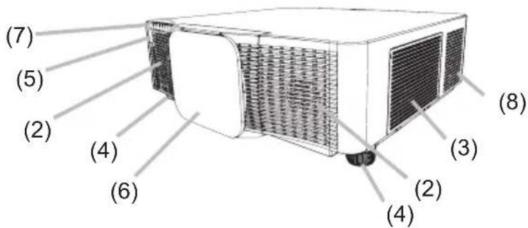
Projector
(1) Lamp cover (109)
The lamp unit is inside.
(2) Speakers (x2) (37, 80)
(3) Filter cover (111)
The air filter and intake vent are inside.
(4) Elevator feet (x2) (40)
(5) Remote sensors (x2) (30, 96)
(6) Lens hole cover
(7) Indicators (5)
(8) Intake vents
(9) Control panel (5)
(10) Status Monitor (31)
(11) AC (AC inlet) (27)
(12) Exhaust vents
(13) Ports (6)
(14) Security bar (26)
(15) Security slot (26)
(16) Safety bar (26)
(17) Battery cover (113)
natural_image
Technical line drawing of an electronic device casing with internal components and ventilation slots (no text or symbols)⚠ WARNING ▶ Do not open or remove any portion of the projector, unless the manuals direct it.
▶ Do not subject the projector to unstable conditions.
▶ Do not apply a shock or pressure to this projector. Remove all the attachments including the power cord and cables, from the projector when carrying the projector.
▶ Do not look into the lens and the openings on the projector while the lamp is on as the projection ray may cause a trouble on your eyes.
▶ Keep any object away from concentrated projection light beam. Blocking the beam causes high temperature and could result in fire or smoke.
⚠ CAUTION ▶ Do not touch the lamp cover and the exhaust vents during use or just after use due to excessive heat.
▶ Do not attach anything onto the lens except the lens cover of this projector because it could damage the lens, such as melting the lens.

(continued on next page)
Part names (continued)
Control panel and Indicators
(1) STANDBY/ON button (35)
(2) INPUT button (38, 57)
(3) MENU button (57)
(4) LENS SHIFT button (41)
(5) ZOOM button (41)
(6) FOCUS - / + buttons (41)
(7) SHUTTER button (52)
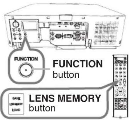
(8) FUNCTION button (33, 42)
(9) FILTER indicator (122)
(10) SHUTTER indicator (52)
(11) SECURITY indicator (108)
(12) LAMP indicator (119 \~ 122)
(13) TEMP indicator (119 \~ 122)
(14) POWER indicator (35, 119 \~ 122)
(continued on next page)
Part names (continued)
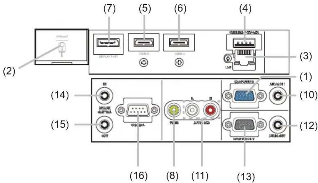
Ports (13\~22)
(1) COMPUTER IN port
(2) HDBaseT port
(3) LAN port
(4) WIRELESS port
(5) HDMI 1 port
(6) HDMI 2 port
(7) DisplayPort port
(8) VIDEO port
(9) SDI port (LWU720i/LHD720i)
(10) AUDIO IN1 port
(11) AUDIO IN2 (L, R) ports
(12) AUDIO OUT port
(13) MONITOR OUT port
(14) REMOTE CONTROL IN port
(15) REMOTE CONTROL OUT port
(16) CONTROL port
LWU620i
Part names (continued)
Remote control
(1) STANDBY button (35)
(2) ON button (35)
(3) ID - 1 / 2 / 3 / 4 buttons (29)
(4) COMPUTER 1 button (38)
(5) COMPUTER 2 button *
(6) VIDEO button (38)
(7) LAN button (38)
(8) USB TYPE A button *
(9) USB TYPE B button *
(10) HDMI 1 button (38)
(11) HDMI 2 button (38)
(12) DisplayPort button (38)
(13) HDBaseT button (38)
(1 4)SDI button
(Supported only for LWU720i/LHD720i) (38)
(15) DIGITAL button *
(16) FOCUS + / - buttons (41)
(17) ZOOM + / - buttons (41)
(18) LENS SHIFT button (41)
(19) LENS MEMORY LOAD / SAVE buttons (42)
(20) LENS LOCK button (95)
(21) OSD MSG button (79)
(22) ▲/▼/◄/► cursor buttons
(23) ENTER button (33, 57)
(24) AV MUTE button (37)
(25) MENU button (57)
(26) GEOMETRY button (74, 75)
(27) PICTURE button (63 \~ 65)
(28) LAMP button (75, 76)
(29) RESET button (57)
(30) ASPECT button (39)
(31) AUTO button (43)
(32) MAGNIFY ON / OFF buttons (51)
(33) VOL + / - buttons (37)
(34) FREEZE button (52)
(35) PbyP button (53)
(36) MY BUTTON - 1 / 2 / 3 / 4 buttons (89, 90)
(37) Battery cover (28)
(38) Wired remote control port (20)
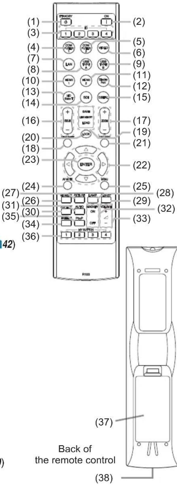
NOTE • Any button marked with * is not supported on this projector (118).
• Each time you press any button (except ID buttons), the ID button of current selected ID number lights (29).
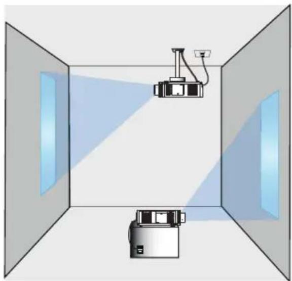
Setting up
Install the projector according to the environment and manner the projector is used in. For the case of installation in a special state such as ceiling mount, the specified mounting accessories and service may be required. Before installing the projector, consult your dealer about your installation.
natural_image
Diagram of a projector setup inside a room with two cameras, showing light paths and no text or symbols.Installing the lens unit
See the manual of the optional lens.
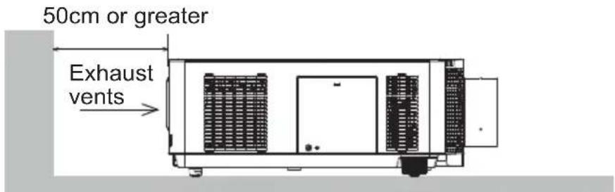
Secure a clearance of 50cm or greater between the exhaust vents and walls, and a clearance of 30cm or greater between the intake vents and walls. Assume that there is enough clearance in the front, back, and top of the projector in the figure below.

text_image
50cm or greater 30cm or greater Exhaust vents Intake vents(continued on next page)
Setting up (continued)
Secure a clearance of 50cm or greater between the exhaust vents and walls. Assume that there is enough clearance in the front, sides, and top of the projector in the figure below.
text_image
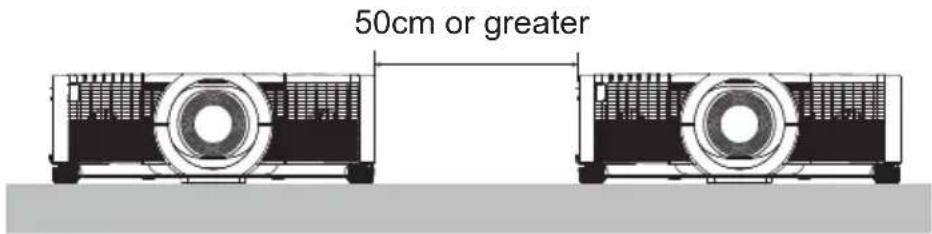
50cm or greater Exhaust ventsSecure a clearance of 50cm or greater when installing the projectors side by side. As for the required clearance not shown in the figure below, follow the installation mentioned above.
text_image
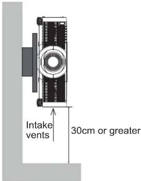
50cm or greaterSecure a clearance of 30cm or greater between the intake vents and walls when installing the projector in portrait mode. As for the required clearance not shown in the figure below, follow the installation mentioned above.
text_image
Intake vents 30cm or greaterArrangement
Refer to tables T-1 to T-2 at the back of Setup Guide as well as the following to determine the screen size and projection distance. The values shown in the table are calculated for a full size screen.
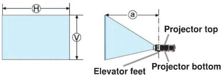
(H) × (V): Screen size
(a): Projection distance
(continued on next page)
Arrangement (continued)
⚠ WARNING ▶ Install the projector where you can access the power outlet easily. If an abnormality should occur, unplug the projector immediately. Otherwise it could cause a fire or electric shock.
▶ Do not subject the projector to unstable conditions. If the projector falls or topples over, it could result in injury or damage to the projector and the surrounding things. Using a damaged projector could result in a fire and an electric shock.
- Do not place the projector in unstable places, such as an inclined surface, places subject to vibration, on top of a wobbly table or cart, or a surface that is smaller than the projector.
- Do not put the projector on its side, front or rear position.
- Do not attach nor place anything on the projector unless otherwise specified in the manual.
- Do not use any mounting accessories except the accessories specified by the manufacturer. Read and keep the manuals of the accessories used.
- For special installation such as ceiling mounting, be sure to consult your dealer beforehand.
- You can install the projector for any direction with specified mounting accessories. Consult with your dealer about such a special installation.
- Remove all the attachments including the power cord and cables, from the projector when carrying the projector.
▶ Do not install the projector near thermally conductive or flammable things. Such things when heated by the projector could result in a fire and burns.
- Do not place the projector on a metal stand.
▶ Do not place the projector where any oils, such as cooking or machine oil, are used. Oil may harm the projector, resulting in malfunction, or falling from the mounted position. Do not use adhesive such as threadlocker, lubricant and so on.
▶ Do not place the projector in a place where it may get wet. Getting the projector wet or inserting liquid into the projector could cause a fire and an electric shock, and damage the projector.
- Do not place the projector near water, such as in a bathroom, kitchen, or poolside.
- Do not place the projector outdoors or by the window.
- Do not place anything containing liquid near the projector.
▶ Do not block the intake vents and exhaust vents of the projector. If the intake vents and exhaust vents of the projector are blocked, the accumulated inside heat may cause fire.
(continued on next page)
Arrangement (continued)
⚠️ CAUTION ▶ Place the projector in a cool place with sufficient
ventilation. The projector may shutdown automatically or may malfunction if its internal temperature is too high.
Using a damaged projector could result in a fire and an electric shock.
- Do not place the projector in direct sunlight or near hot objects such as heaters.
- Do not place the projector where the air from an air conditioner or similar unit directly blows on it.
- Do not place the projector on carpet, cushions or bedding.
- Do not stop up, block nor cover the projector's vent holes. Do not place anything around the projector that could be sucked in or stuck to the projector's intake vents.
- Do not place the projector at places that are exposed to magnetic fields, doing so can cause the cooling fans inside the projector to malfunction.
▶ Avoid placing the projector in smoky, humid or dusty place. Placing the projector in such places could cause a fire, an electric shock and malfunction of the projector.
- Do not place the projector near humidifiers. Especially for an ultrasonic humidifier, chlorine and minerals contained in tap water are atomized and could be deposited in the projector causing image degradation or other problems.
- Do not place the projector in a smoking area, kitchen, passageway or by the window.
NOTICE • Position the projector to prevent light from directly hitting the projector's remote sensor.
- Positional deviation or distortion of a projected image, or shift of the focus may occur due to ambient conditions, and so on. They tend to occur until the operation becomes stable, especially within about 30 minutes after the lamp is turned on. Check and readjust them as necessary.
- Do not place the projector in a place where radio interference may be caused.
- Set the ALTITUDE of the SERVICE item in the OPTION menu correctly. It is recommended to leave it at AUTO usually (94). If the projector is used with a wrong setting, it may cause damage to the projector itself or the parts inside.
- Keep heat-sensitive things away from the projector. Otherwise, they may be damaged by the heat from the projector.
NOTE • When the temperature inside the projector rises high, it may cause the high rotation of the fan for cooling temporarily.
Connecting with your devices
Before connecting the projector to a device, consult the manual of the device to confirm that the device is suitable for connecting with this projector and prepare the required accessories, such as a cable in accord with the signal of the device. Consult your dealer when the required accessory did not come with the projector or the accessory is damaged.
After making sure that the projector and the devices are turned off, perform the connection, according to the following instructions. Refer to the figures in subsequent pages.
Before connecting the projector to a network system, read Network Guide too.
⚠ WARNING ▶ Use only the appropriate accessories. Otherwise it could cause a fire or damage the projector and devices.
- Use only the accessories specified or recommended by the projector's manufacturer. It may be regulated under some standard.
- Neither disassemble nor modify the projector and the accessories.
- Do not use the damaged accessory. Be careful not to damage the accessories.
⚠️ CAUTION Route a cable so that it is neither stepped on nor pinched out.
▶ For a cable with a core at only one end, connect the end with the core to the projector. That may be required by EMI regulations.
NOTE • Do not turn on or off the projector while connected to a device in operation, unless directed in the manual of the device. Otherwise it may cause malfunction in the device or projector.
- The function of some input ports can be selected according to your requirements. Check the reference page indicated beside each port in the following illustration. (14\~22)
- Be careful not to mistakenly connect a connector to a wrong port. Otherwise it may cause malfunction in the device or projector.
- When connecting a connector to a port, make sure that the shape of the connector fits the port.
- Tighten the screws to connect a connector equipped with screws to a port.
- Use the cables with straight plugs, not L-shaped ones, as the input ports of the projector are recessed.
About Plug-and-Play capability
- Plug-and-Play is a system composed of a computer, its operating system and peripheral equipment (such as display devices). This projector is VESA DDC 2B compatible. Plug-and-Play can be used by connecting this projector to a computer that is VESA DDC (display data channel) compatible.
- Take advantage of this feature by connecting a computer cable to the COMPUTER IN port (DDC 2B compatible). Plug-and-Play may not work properly if any other type of connection is attempted.
- Use the standard drivers in your computer as this projector is a Plug-and-Play monitor.
(continued on next page)
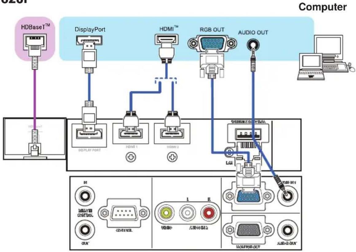
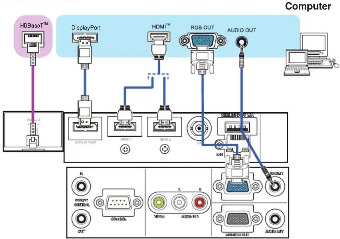
Connecting with your devices (continued)
LWU620i
flowchart
graph TD
    A["HDBase™"] --> B["DisplayPort"]
    B --> C["HDMI"]
    C --> D["RGB OUT"]
    D --> E["AUDIO OUT"]
    E --> F["Computer"]
    subgraph HDBaseT™
        G["+"]
        H["+"]
        I["+"]
        J["+"]
        K["+"]
    end
    subgraph DisplayPort
        L["+"]
        M["+"]
        N["+"]
        O["+"]
        P["+"]
    end
    subgraph HDMI
        Q["+"]
        R["+"]
        S["+"]
        T["+"]
    end
    subgraph RGB OUT
        U["+"]
        V["+"]
        W["+"]
        X["+"]
    end
    subgraph Audio OUT
        Y["+"]
        Z["+"]
        AA["+"]
        AB["+"]
    end
LWU720i/LHD720i
flowchart
graph TD
    A["Computer"] --> B["HDBaseT™"]
    B --> C["DisplayPort"]
    C --> D["HDMI1"]
    C --> E["HDMI2"]
    C --> F["RGB OUT"]
    C --> G["AUDIO OUT"]
    B --> H["HDBaseT™"]
    H --> I["DISPLAY PORT"]
    I --> J["HDMI1"]
    I --> K["HDMI2"]
    I --> L["50Hz"]
    L --> M["LMM"]
    M --> N["HD8H1"]
    M --> O["HD8H2"]
    M --> P["HD8H3"]
    M --> Q["HD8H4"]
    M --> R["HD8H5"]
    M --> S["HD8H6"]
    M --> T["HD8H7"]
    M --> U["HD8H8"]
    M --> V["HD8H9"]
    M --> W["HD8H10"]
(continued on next page)
Connecting with your devices (continued)
NOTE • Before connecting the projector to a computer, consult the computer's manual and check the compatibility of the signal level, the synchronization methods and the display resolution output to the projector.
- Some signal may need an adapter to input this projector.
- Some computers have multiple screen display modes that may include some signals which are not supported by this projector.
- Although the projector can display signals with a resolution up to UXGA (1600x1200) or up to W-UXGA (1920x1200), the signal is converted to the projector's panel resolution before being displayed. The best display performance is achieved if the resolutions of the input signal and the projector panel are identical.
- If you connect this projector and a notebook computer, you must output the display to an external monitor, or output simultaneously to the internal display and an external monitor. Consult the computer's manual for the setting.
- Depending on the input signal, the automatic adjustment function of this projector may take some time and not function correctly.
- A composite sync signal or sync-on-green signal may confuse the automatic adjustment function of this projector (71).
- If the automatic adjustment function does not work correctly, you may not see the dialog to set the display resolution. In such a case, use an external display device. You may see the dialog and set an appropriate display resolution.
- Use DisplayPort cables conforming to the DisplayPort standard.
- Use of DisplayPort cables not conforming to the DisplayPort standard may cause abnormal operations such as images with interruption or not displayed.
- When the projector is connected to the output of the computer with an early type of chipset or graphics card that supports the DisplayPort, the projector and/or computer may not operate normally. In that case, turn off the projector and/or computer, then turn on again.
- When connecting the output of the DisplayPort to the input of the projector, use of the computer with the newest chipset or graphics card is recommended.
- Commercially available DisplayPort cables may have a lock system. When unplugging the cable, push the button on the connector of the cable.
- Some computers may take a long time to display the image.
- Power supply is available to the connected device with the input port of DisplayPort. However, it is not available to the computer.
- When the signal from the device with a signal converting adapter is connected to the input port of DisplayPort, the image may not be displayed.
- Use a commercially available converter when connecting the output port of HDMI of the computer with the input port of DisplayPort of the projector.
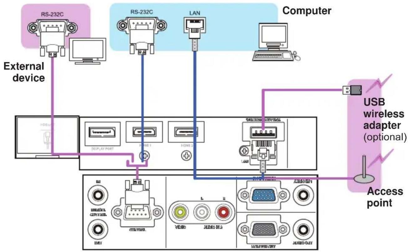
Connecting with your devices (continued)
LWU620i
flowchart
graph TD
    A["External device"] --> B["RS-232C"]
    A --> C["RS-232C"]
    A --> D["LAN"]
    A --> E["Computer"]
    B --> F["DISPLAY PORT"]
    C --> G["PGM 1"]
    C --> H["PGM 2"]
    D --> I["USB wireless adapter (optional)"]
    E --> J["USB wireless adapter (optional)"]
    K["Access point"] --> L["USB wireless adapter (optional)"]
    M["External device"] --> N["USB wireless adapter (optional)"]
    style A fill:#f9f,stroke:#333
    style B fill:#ccf,stroke:#333
    style C fill:#ccf,stroke:#333
    style D fill:#ccf,stroke:#333
    style E fill:#ccf,stroke:#333
    style K fill:#cfc,stroke:#333
    style M fill:#cfc,stroke:#333
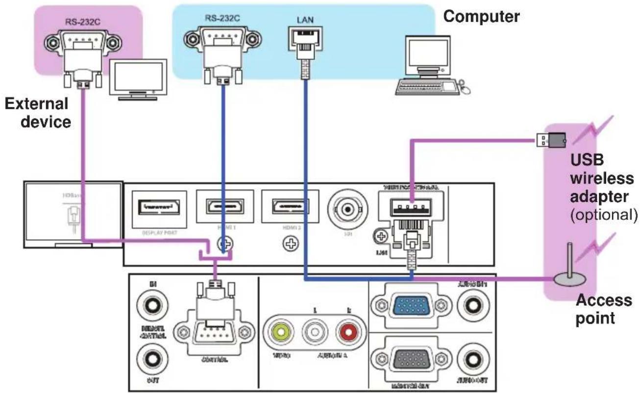
LWU720i/LHD720i
flowchart
graph TD
    A["External device"] --> B["RS-232C"]
    A --> C["RS-232C"]
    A --> D["LAN"]
    A --> E["Computer"]
    B --> F["DISPLAY PORT"]
    C --> G["HDMI 1"]
    C --> H["HDMI 2"]
    C --> I["SDI"]
    D --> J["USB wireless adapter (optional)"]
    E --> K["Access point"]
    L["USB wireless adapter (optional)"] --> M["USB wireless adapter (optional)"]
    N["Access point"] --> O["USB wireless adapter (optional)"]
    P["External device"] --> Q["Display Port"]
    P --> R["Control"]
    P --> S["LED Control"]
    P --> T["USB Digital"]
    P --> U["USB Digital"]
(continued on next page)
Connecting with your devices (continued)
⚠ WARNING ▶ Heat may build up in the USB wireless adapter, to avoid possible burns disconnect the projector power cord for 10 minutes before touching the adapter.
▶ When using the USB wireless adapter, use the supplied adapter cover or terminal cover (24, 25).
⚠️ CAUTION ▶ Before connecting the projector to a network system, obtain the consent of the administrator of the network.
▶ Do not connect the LAN port to any network that might have the excessive voltage.
The designated USB wireless adapter sold as an option is required to use the wireless network function of this projector. Before connecting the USB wireless adapter, turn off the power of the projector and disconnect the power cord. Do not use any extension cable or device when connecting the adapter to the projector.
To connect both the LAN cable and USB wireless adapter to the projector, use a LAN cable that is flat on the side where the plug's wire is visible. Otherwise, both of them cannot be connected correctly, or the wire may break (malfunction).
(continued on next page)
Connecting with your devices (continued)
LWU620i
flowchart
graph TD
    A["VCR/DVD/Blu-ray Disc™ player"] --> B["VIDEO"]
    A --> C["AUDIO OUT L R"]
    A --> D["HDMI™ Cri/Pr Cb/Pb Y"]
    A --> E["COMPONENT"]
    B --> F["DISPLAY PORT"]
    C --> G["HDMI 1"]
    D --> H["HDMI 2"]
    E --> I["SHELLIPT OFF/AA"]
    F --> J["COM/POS"]
    G --> K["MODS > AUDIO/012"]
    H --> L["MODS+PER+UT"]
    I --> M["MODS M1"]
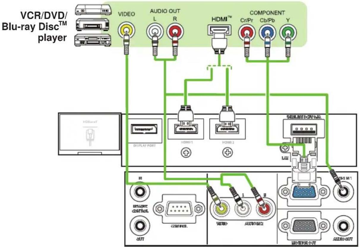
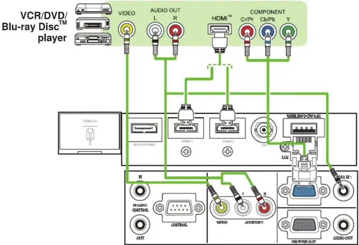
LWU720i/LHD720i
flowchart
graph TD
    A["VCR/DVD/Blu-ray Disc™ player"] --> B["VIDEO"]
    A --> C["AUDIO OUT L R"]
    A --> D["HDMI™ Cr/Pr Cb/Pb Y"]
    A --> E["COMPONENT"]
    B --> F["DISPLAY PORT"]
    C --> G["HDMI 1"]
    D --> H["HDMI 2"]
    E --> I["SCL"]
    F --> J["TV"]
    G --> K["RESAVE CONTROL"]
    H --> L["OUTPUT"]
    I --> M["UN"]
    J --> N["UN"]
    K --> O["UN"]
    L --> P["UN"]
    M --> Q["UN"]
    N --> R["UN"]
    O --> S["UN"]
    P --> T["UN"]
    Q --> U["UN"]
    R --> V["UN"]
    S --> W["UN"]
    T --> X["UN"]
(continued on next page)
Connecting with your devices (continued)
About HDBaseT™ connection
- HDBaseT is a technology to transmit image, sound, ethernet or serial control signal using a LAN cable.
- Go to the following URL regarding the device of other company that supports HDBaseT and has been confirmed compatible with this projector.
http://www.christiedigital.com
LAN or HDBaseT input port can be selected as ethernet signal input by switching in the menu.
- Use LAN cables of up to 100m long. Exceeding this length, the image and sounds are deteriorated, and even experience malfunction on LAN transmission.
NOTE • The HDMI ports of this model are compatible with HDCP (High-bandwidth Digital Content Protection) and therefore capable of displaying video signals from HDCP compatible DVD players or the like.
- The HDMI ports support the following signals: For Video signals, refer to User's Manual (detailed) Technical. Audio signal : Format Linear PCM Sampling frequency 48kHz / 44.1kHz / 32kHz
- This projector can be connected with another equipment that has HDMI ^™ connector, but with some equipment the projector may not work properly, something like no video.
- Qualified cable is required for HDBaseT connection.
- Use an HDMI™ cable that has the HDMI™ logo.
- Use a Category 2-certified HDMI™ cable to input 1080p@50/60 signal to the projector.
- When the projector is connected with a device having DVI connector, use a DVI to HDMI™ cable to connect with the HDMI™ input.
- The HDMI™ cables might come off due to the lack of a mechanical lock on the cables and connectors. Fasten the HDMI cables by using the HDMI cable holder and the Cable tie to prevent them from coming off (23).
(continued on next page)
Connecting with your devices (continued)
LWU620i
flowchart
graph TD
    A["Another projector"] -->|Wired Remote control| B["Monitor"]
    B --> C["Speakers (with an amplifier)"]
    C --> D["USB drive"]
    D --> E["Display port"]
    D --> F["USB port"]
    D --> G["USB port"]
    D --> H["USB port"]
    D --> I["USB port"]
    D --> J["USB port"]
    D --> K["USB port"]
    D --> L["USB port"]
    D --> M["USB port"]
    D --> N["USB port"]
    D --> O["USB port"]
    D --> P["USB port"]
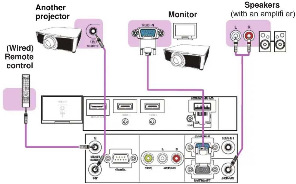
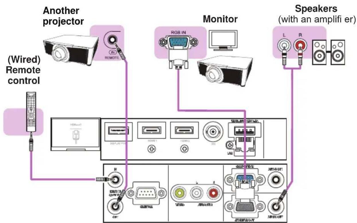
LWU720i/LHD720i
flowchart
graph TD
    A["Another projector"] --> B["Monitor"]
    B --> C["Speakers (with an amplifier)"]
    D["(Wired) Remote control"] --> A
    E["Radio"] --> A
    F["Display"] --> G["Device 1"]
    F --> H["Device 2"]
    I["Radio"] --> J["Device 3"]
    K["Radio"] --> L["Device 4"]
    M["Radio"] --> N["Device 5"]
    O["Radio"] --> P["Device 6"]
    Q["Radio"] --> R["Device 7"]
    S["Radio"] --> T["Device 8"]
    U["Radio"] --> V["Device 9"]
    W["Radio"] --> X["Device 10"]
    Y["Radio"] --> Z["Device 11"]
    AA["Radio"] --> AB["Device 12"]
    AC["Radio"] --> AD["Device 13"]
    AE["Radio"] --> AF["Device 14"]
    AG["Radio"] --> AH["Device 15"]
(continued on next page)
Connecting with your devices (continued)
NOTE • To use a wired remote control, connect a wired remote control to the REMOTE CONTROL IN port. You can also connect another projector to the REMOTE CONTROL OUT port to control it from the wired remote control. You can use this projector as a remote control-relay with the REMOTE CONTROL IN and OUT ports. To connect the wired remote control or another projector to the REMOTE CONTROL IN or OUT ports, use audio cables with 3.5 mm diameter stereo mini plugs. This function is useful when a wireless remote signal may not reliably reach the projector.
(continued on next page)
Setting up
Connecting with your devices (continued)
LWU720i/LHD720i
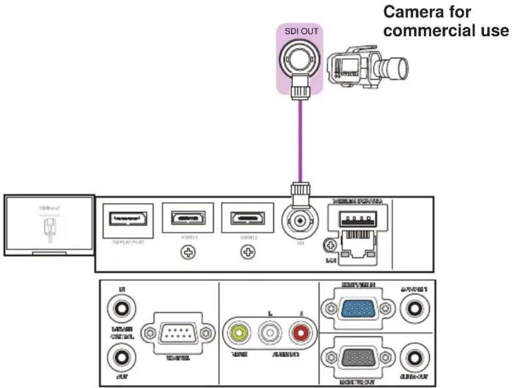
text_image
Camera for commercial use SDI OUT HDBus1 3D/PLAY PORT +30011 +30012 +30013 HDMI MUI HDMI +30011 +30012 +30013 +30014 +30015 +30016 +30017 +30018 +30019 +30020 +30021 +30022 +30023 +30024 +30025 +30026 +30027 +30028 +30029 +30030 +30031 +30032 +30033 +30034 +30035 +30036 +30037 +30038 +30039 +30040 +30041 +30042 +30043 +30044 +30045 +30046 +30047 +30048 +30049 +30050 +30051 +30052 +30053 +30054 +30055 +30056 +30057 +30058 +30059 +30060 +30061 +30062 +30063 +30064 +30065 +30066 +30067 +30068 +30069 +30070 +30071 +30072 +30073 +30074 +30075 +30076 +30077 +30078 +30079 +30080 +30081 +30082 +30083 +30084 +30085 +30086 +30087 +30088 +30089 +30090 +30091 +30092 +30093 +30094 +30095 +30096 +30097 +301NOTE • The SDI port of this model supports the following SDI signals:
SD-SDI signal: conforming to SMPTE ST 259-C standard
YCBCR 4:2:2 10-bit
480i, 576i
Single link HD-SDI signal: conforming to SMPTE ST 292 standard
YPBPR 4:2:2 10-bit
720p@50/60, 1080i@50/60, 1080sf@25/30
3G-SDI Level-A signal: conforming to SMPTE ST 424 standard
YPBPR 4:2:2 10-bit
1080p@50/60
- This projector can be connected with other equipment that has SDI connector, but with some equipment the projector may not work properly.
- Use a cable of 5CFB or greater (5CFB, 7CFB, and so on), or Belden 1694A or greater to transmit the image properly. Use a cable with a length of 100 ~m or less.
- Setting by MENU is necessary depending on a connected device.
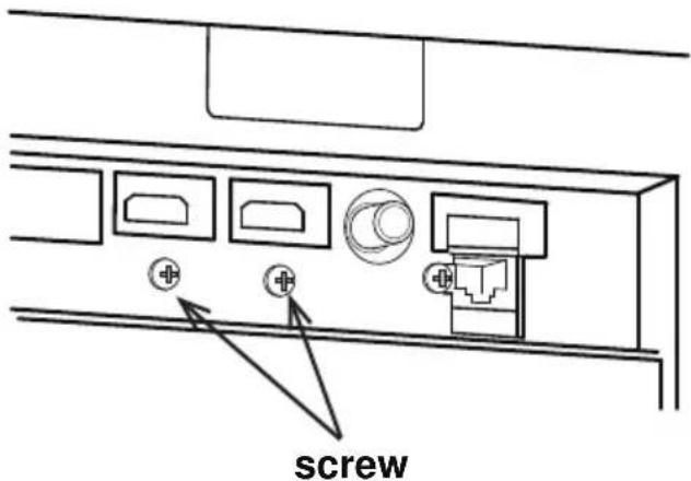
Fastening the cables
Remove the screw located on the lower side of HDMI connector and use it to attach the HDMI cable holder.
text_image
screwFasten the HDMI cables by using the HDMI cable holder and the cable tie to prevent them from coming off. Use a cable tie with the size of 2.0 x 4.0mm or smaller.
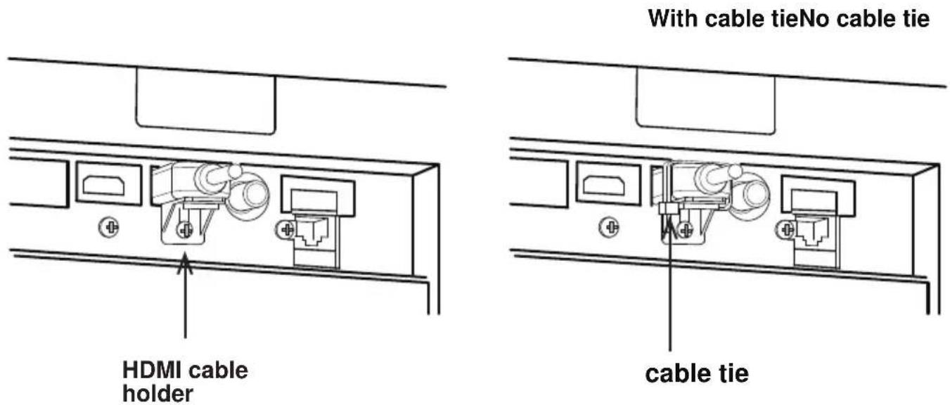
text_image
With cable tieNo cable tie HDMI cable holder cable tie⚠ WARNING ▶ Do not fasten the cables other than HDMI.
⚠️ CAUTION ▶ To fasten the cable, use a supplied cable tie or plastic tie with the size of 2.0 x 4.0mm or smaller. A metallic tie may cause damage to the cables and tie holder.
▶ Do not bind the cables too tightly. The cables or the hole might be damaged.
Fastening the adapter cover
When using the USB wireless adapter, use the supplied adapter cover for theft prevention.
USB wireless adapter: USB-WL-11N-NS
Temperature range: 0 \~ 45°C(operating)
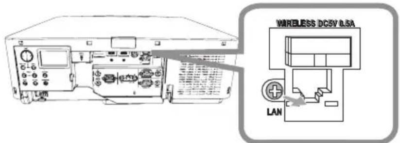
Loosen the screw on the bottom left of the WIRELESS port.
1.
text_image
WIRELESS DC5V L5A LAN- Insert the tab of the cover into the hole at the upper right of the WIRELESS port in the direction of the arrow.
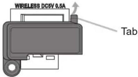
text_image
WIRELESS DC5V 0.5A Tab- Align the screw holes on the projector and the cover. Then insert the screw removed from the projector into the hole and tighten the screw.
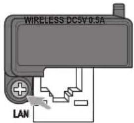
text_image
WIRELESS DC5V 0.5A LAN⚠ WARNING ▶ Keep small parts away from children and pets. Take care not to put in the mouth.
▶ Heat may build up in the USB wireless adapter, to avoid possible burns disconnect the projector power cord for 10 minutes before touching the adapter.
Attaching the terminal cover

text_image
Terminal cover Hook Insert the two claws of the termin the case and confirm two hooks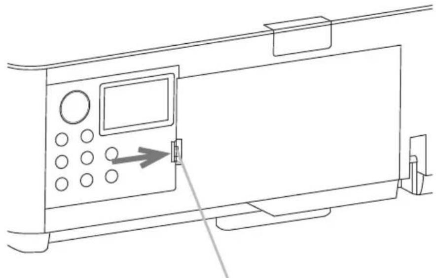
natural_image
Line drawing of a device panel with control buttons and an arrow pointing to the door (no text or symbols)When detaching the terminal cover, push the hook in the direction of the arrow and pull it forward.
NOTE • Do not attach the adapter cover when attaching the terminal cover.
Using the security bar and slot
A commercially available anti-theft chain or wire can be attached to the security bar on the projector. Refer to the figure to choose an anti-theft chain or wire.
This projector has the security slot for the Kensington lock.
For details, see the manual of the security tool.
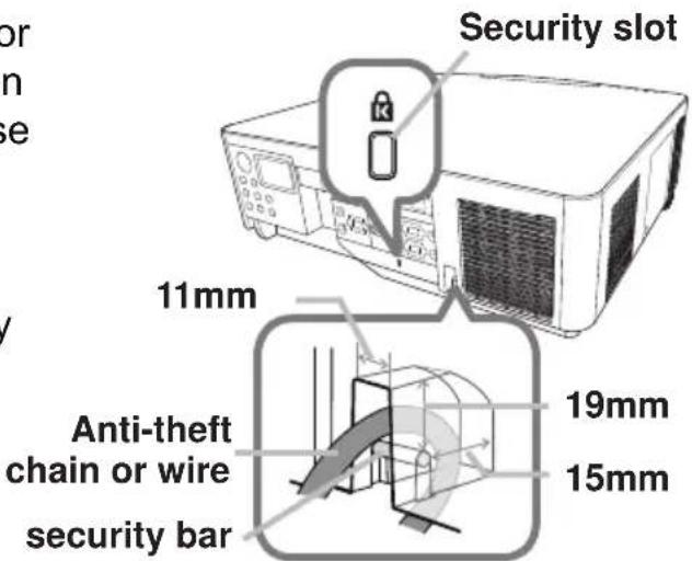
text_image
Security slot 11mm Anti-theft chain or wire security bar 19mm 15mm⚠ WARNING ▶ Do not use the security bars and slot to prevent the projector from falling down, as it is not designed for it.
⚠️ CAUTION ▶ Do not place anti-theft chain or wire near the exhaust vents. It may become too hot.
NOTE • The security bar and slot is not comprehensive theft prevention measures. It is intended to be used as supplemental theft prevention measure.
- The safety bar (4) can be used for the same purpose as the security bar.
Connecting power supply
- Put the connector of the power cord into the AC (AC inlet) of the projector.
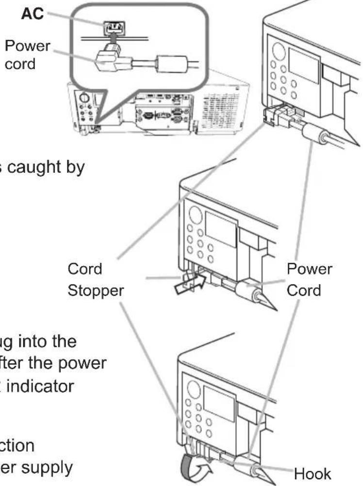
text_image
AC Power cord caught by Cord Stopper Power Cord g into the ter the power indicator ction er supply Hook-
Push the Cord Stopper until it is caught by the hook.
-
Firmly plug the power cord's plug into the outlet. In a couple of seconds after the power supply connection, the POWER indicator lights up in steady orange.
When the DIRECT POWER ON function activated, the connection of the power supply makes the projector turn on.
⚠ WARNING ▶ Do not connect the projector to a power supply while no lens unit is attached to it.
▶ Use extra caution when connecting the power cord, as incorrect or faulty connections may result in fire and/or electrical shock.
- Do not touch the power cord with a wet hand.
- Only use the power cord that came with the projector. If it is damaged, consult your dealer to get a new one. Never modify the power cord.
- Only plug the power cord into an outlet whose voltage is matched to the power cord. The power outlet should be close to the projector and easily accessible. Remove the power cord for complete separation.
- Do not distribute the power supply to multiple devices. Doing so may overload the outlet and connectors, loosen the connection, or result in fire, electric shock or other accidents.
- Connect the ground terminal for the AC inlet of this unit to the ground terminal of the building using an appropriate power cord (bundled).
NOTICE • This projector is also designed for IT power systems with a phase-to-phase voltage of 220 to 240 V.
Remote control
Installing the batteries
Insert the batteries into the remote control before using it. If the remote control starts to malfunction, replace the batteries. If not using the remote control for long period, remove the batteries from the remote control and store them in a safe
place.
- Holding the hook part of the battery cover, remove it.
-
Align and insert the two AA batteries according to their plus and minus terminals as indicated in the remote control. (Use the appropriate AA carbon-zinc or alkaline batteries (non-rechargeable) according to laws and regulations. Batteries not included.)
-
Replace the battery cover in the direction of the arrow and snap it back into place.
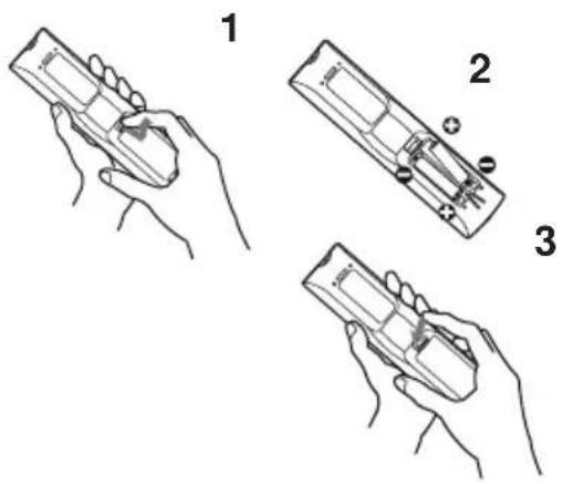
text_image
Diagram showing three steps of a handheld device with labeled parts, likely illustrating a manual or mechanical operation.⚠ WARNING ▶ Always handle the batteries with care and use them only as directed. Improper use may result in battery explosion, cracking or leakage, which could result in fire, injury and/or pollution of the surrounding environment.
- Be sure to use only the batteries specified. Do not use batteries of different types at the same time. Do not mix a new battery with used one.
- Make sure the plus and minus terminals are correctly aligned when loading a battery.
- Keep a battery away from children and pets.
- Do not recharge, short circuit, solder or disassemble a battery.
- Do not place a battery in a fire or water. Keep batteries in a dark, cool and dry place.
- If you observe battery leakage, wipe out the leakage and then replace a battery. If the leakage adheres to your body or clothes, rinse well with water immediately.
- Obey the local laws on disposing the battery.
Using the REMOTE ID function
Use this function to control specific projectors by the remote control assigned the same ID number when you use multiple projectors of the same type at the same time.
Assign an ID number to each projector before using the REMOTE ID item in the SERVICE menu of the OPTION menu (96). Press the ID button with the same ID number as assigned to the projector you are going to control. The ID button selected lights for several seconds.
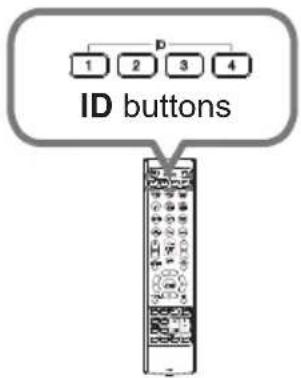
text_image
1 2 3 4 ID buttonsNOTE • Each time you press any button (except ID buttons), the ID button of current selected ID number lights.
• To confirm the projector's current ID, press any ID button for three seconds. Its number is shown on each screen regardless of set ID of projector.
Changing the frequency of remote control signal
The accessory remote control has the two choices on signal frequency Mode 1:NORMAL and Mode 2:HIGH. If the remote control does not function properly, attempt to change the signal frequency.
To set the Mode, press the combination of two buttons listed below simultaneously for about three seconds.
(1) Set to Mode 1: NORMAL
MENU and MY BUTTON-4 buttons
(2) Set to Mode 2:HIGH
AV MUTE and MY BUTTON-1 buttons
The REMOTE FREQ. in the SERVICE
item of the OPTION menu (96) of the projector to be controlled should be set to the same mode as the remote control.
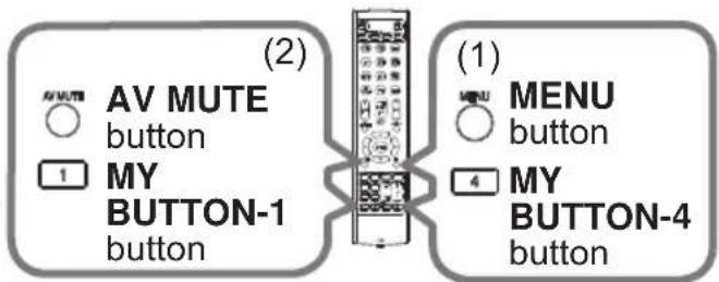
text_image
(2) AV MUTE button MY BUTTON-1 button (1) MENU button MY BUTTON-4 buttonAbout the remote control signal
The remote control works with the projector's remote sensor.
This projector has two remote sensors on the front and back sides.
The sensors can sense signals within the following range:
60 degrees (30 degrees to the left and right of the sensor) within about 3 meters.
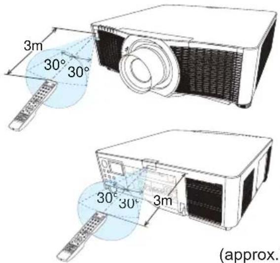
text_image
3m 30° 30° 30° 30° 3m (approx.)(approx.)
NOTE • You can deactivate one of the sensors using the REMOTE RECEIV. item in the SERVICE menu of the OPTION menu (96).
- The remote control signal reflected in the screen may be available. If it is difficult to send the signal to the sensor directly, try to make the signal reflect.
- The remote control uses infrared light to send signals to the projector (Class 1 LED). Use the remote control in an area free from obstacles that could block the remote control's signal to the projector.
- The remote control may not work correctly if strong light (such as direct sun light) or light from an extremely close range (such as from an inverter fl fluorescent lamp) shines on the remote sensor of the projector. Adjust the position of projector avoiding those lights.
Status Monitor
The Status Monitor is the sub LCD in the rear panel. The Status Monitor displays the present condition of the projector including errors, setup information and error history.
Status Monitor
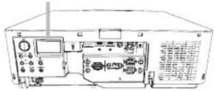
natural_image
Line drawing of a vintage electronic device front panel with control knobs and buttons (no text or symbols visible)Displaying the condition of the projector
If no buttons have been operated, the Status Monitor displays as below depending on the condition of the projector.
NOTE • The Status Monitor displays nothing while the projector is in standby mode if the STANDBY MODE item of SETUP menu is set to POWER SAVE (78).
- When INSTALLATION in the SETUP menu is set to FRONT / CEILING or REAR / CEILING, the contents on the Status Monitor are displayed upside down (77).
○ In a normal state
The Status Monitor displays the state of the projector in three lines.

: Displays the condition of the projector. While the lamp is on, the selected port is displayed.
Displayed conditions are as below;
STANDBY: The projector is in standby mode.
WARM UP: The projector is warming up.
SEARCHING: The projector is searching an input signal.
COOL DOWN: The projector is cooling down.
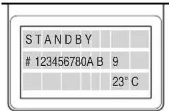
text_image
STANDBY123456780A B 9
23°Cexample

: Displays the condition of the detected input signal while the lamp is on. Otherwise, displays the serial number of the projector.
Displayed conditions are as below;
SYNC OUT: Detected input signal is out of specified range.
NO SIGNAL: There is no input signal.
CONNECTED: The projector has connected to the network or the computer and some image is transferred to the projector while the LAN port is selected.
HOLD: The projector has connected to the network but no image is transferred while the LAN port is selected.
NOT CONNECTED: The projector is not connected to the network or the computer while the LAN port is selected.

: Displays supplied voltage and peripheral temperature in Celsius while the lamp is on.
(continued on next page)
Displaying the condition of the projector (continued)
NOTE • While the projector is searching an input signal in normal condition, nothing is displayed on the 2nd line of the monitor.
- Displayed temperature might differ from actual peripheral temperature because the displayed temperature is measured inside of the projector.
○ In error state
The Status Monitor displays a warning of an error with larger letters. Resolve the errors referring to the table of the sections "Related messages" (116 \~ 118) and "Regarding the indicator lamps" (119 \~ 123) when the warning is displayed.
Warnings;
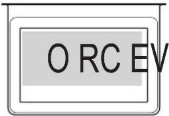
text_image
O RC EVexample
AIR (AIR FLOW): The internal temperature is rising. Refer to the description of the message, "CHECK THE AIR FLOW" in the table (117).
COLD: The interior portion may have become over cooled. Refer to the LAMP and TEMP indicators alternatively blinking in the table (122).
FILTR (FILTER): Clean the air filter. Refer to the LAMP and TEMP indicators simultaneous blinking in the table (121).
SHUTR: Shutter Error Contact your dealer or service company.
SHIFT: Lens Shift Error Contact your dealer or service company.
Errors;
COVER: The lamp cover has not been properly fixed. Refer to the LAMP indicator blinking in the table (120).
FAN: The cooling fan is not operating. Refer to the TEMP indicator blinking in the table (120).
LAMP: The lamp does not light. Refer to the LAMP indicator lighting in the table (120).
TEMP: The projector's interior becomes over heated. Refer to the TEMP indicator lighting in the table (121).
ACBLK: Refer to the LAMP indicator lighting in the table (120).
OTHER: Errors other than the above (121).
NOTE • When one of the warnings of FAN, LAMP, COVER, TEMP is displayed, the backlight blinks at the same time.
Displaying the log
The present setup information and the error history can be displayed on the Status Monitor with button operation.
NOTE • While the projector is warming up, button presses are ignored.
- The Status Monitor displays nothing or no button presses for the monitor are available while the projector is in standby mode if the STANDBY MODE item of SETUP menu is set to POWER SAVE (78).
- Both of the Status Monitor and the OSD menu cannot be operated at same time.
When the projector is in a normal condition, or displays one of the warnings of AIR FLOW, COLD or FILTER errors, press the FUNCTION button on the control panel, press the ENTER button on the remote control for three seconds or press one of the MY BUTTON buttons if assigned as STATUS MONITOR. The backlight of the monitor turns on.
To display the setup information including usage time
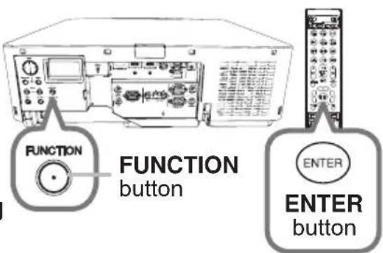
text_image
FUNCTION button ENTER ENTER buttonUse the ◀/▶ buttons to switch display.
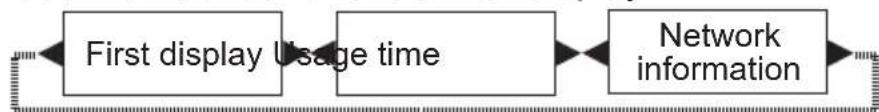
flowchart
graph LR
    A["First display Usage time"] --> B["Network information"]
    B --> C["End"]
Usage time: The Status Monitor displays the lamp hours (usage time of the present lamp), the filter hours (usage time of the air filter) and the projector usage time.
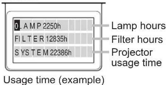
text_image
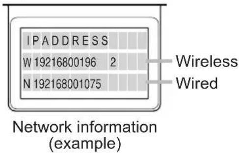
0 LAMP 2250h FILTER 12835h SYSTEM 22386h Usage time (example) Lamp hours Filter hours Projector usage timeNetwork information: The network information is displayed over three pages.
Use the ▲/▼ buttons to switch the page.
Displayed information in each page is as below;
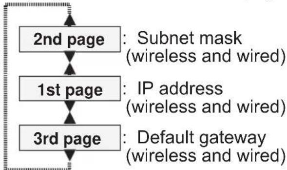
flowchart
graph TD
    A["2nd page"] --> B["1st page"]
    B --> C["3rd page"]
    A --> D["Subnet mask\n(wireless and wired)"]
    B --> E["IP address\n(wireless and wired)"]
    C --> F["Default gateway\n(wireless and wired)"]
(continued on next page)
text_image
IP ADDRESS W 19216800196 2 N 192168001075 Network information (example) Wireless WiredDisplaying the log (continued)
NOTE • The Status Monitor and its backlight returns to the first state before the FUNCTION or ENTER button was pressed when any button except cursor buttons is pressed, or after about 30 seconds without button operation.
- The projector usage time is the total lamp time from the projector is manufactured. It is not reset by using LAMP HOURS in the SETUP menu (75).
- If the ▲/▼ buttons are pressed while the usage time is displayed, the usage time switches to the past one when an error occurred.
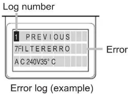
○ To display error history
Press the ▲ button to display the previous error log. If a warning has been displayed, the first previous error log is the present error currently occurring. The Status Monitor displays the log number, occurred error, the supplied voltage and peripheral temperature at that time. Press the ▶ button to display the usage time when each error occurred.
Use the ▲/▼ buttons to switch the log. The display switches with the ◀/▶ buttons at each log. Up to 10 error logs including the present one can be displayed.
text_image
Log number 1 PREVIOUS 7FILTERERRO AC 240V35°C Error Error log (example)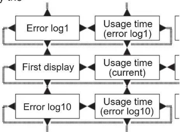
flowchart
graph TD
    A["Error log1"] --> B["Usage time (error log1)"]
    C["First display"] --> D["Usage time (current)"]
    E["Error log10"] --> F["Usage time (error log10)"]
    B --> G["End"]
    D --> H["End"]
    F --> I["End"]
NOTE • The Status Monitor and its backlight returns to the first state before the FUNCTION or ENTER button was pressed when any button except cursor buttons is pressed, or after about 30 seconds without button operation.
- If no error or less than 10 errors have occurred, "NO DATA" is displayed regardless of what error occurred in the error log.
Power on/off
Turning on the power
- Make sure that the power cord is firmly and correctly connected to the projector and the outlet.
- Make sure that the POWER indicator is lighted in steady orange (119). Then remove the lens cover.
- Press STANDBY/ON button on the projector or the ON button on the remote control.
POWER indicator
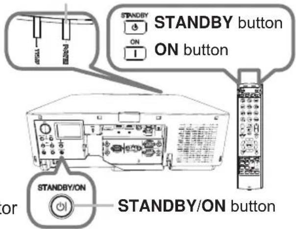
text_image
STANDBY STANDBY button ON ON button STANDBY/ON OR STANDBY/ON buttonThe projection lamp lights up and the POWER indicator begins blinking in green. When the power is completely on, the indicator stops blinking and light in a steady green (119).
To display the picture, select an input signal according to the section Selecting an input signal (38).
Turning off the power
- Press the STANDBY/ON button on the projector or the STANDBY button on the remote control.
The message "Power off?" appears on the screen for about five seconds.
- Press the STANDBY/ON or STANDBY button again while the message appears.
The projector lamp goes off, and the POWER indicator begins blinking in orange. The POWER indicator stops blinking and lights in a steady orange when the lamp cooling is completed (119).
- Attach the lens cover, after the POWER indicator turns to steady orange.
Do not turn the projector on for about 10 minutes or more after turning it off. Do not turn the projector off shortly after turning it on. Such operations might cause the lamp to malfunction or shorten the lifetime of some parts including the lamp.
(continued on next page)
Power on/off
⚠ WARNING ▶ A strong light is emitted when the projector's power is on. Do not look into the lens of the projector or look inside of the projector through any of the projector's openings as the projection ray may cause a trouble on your eyes.
▶ Keep objects away from concentrated projection light beam. Blocking the beam by something causes high temperature and could result in fire or smoke.
▶ Do not touch around the lamp cover and the exhaust vents during use or just after use, as it is too hot.
NOTE • Turn the power on/off in the right order. Power on the projector prior to the connected devices.
- This projector can automatically turn on/off. Refer to the DIRECT POWER ON (88) and AUTO POWER OFF (88) items of the OPTION menu.
Operating
Adjusting the volume
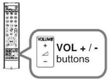
- Use the VOL + / - buttons to adjust the volume. A dialog appears on the screen to help you in adjusting the volume. If you do nothing, the dialog automatically disappears after a few seconds.
text_image
VOLUME + - VOL + / - buttonsNOTE • When ✗is selected for current picture input port, the volume adjustment is disabled. See AUDIO SOURCE item of AUDIO menu (80).
- If the projector is in the standby mode, the volume is adjustable when both of the following conditions are true:
- An option other than is selected for AUDIO OUT STANDBY in the AUDIO SOURCE item of the AUDIO menu (80).
- NORMAL is selected in the STANDBYMODE item of the SETUP menu (78).
Temporarily turning off the screen and audio
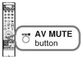
- Press AV MUTE button on the remote control. The BLANK screen is displayed instead of the screen of input signals and the sound from the internal speakers is muted. Refer to the BLANK item in MENU PREFERENCES about the BLANK screen (81).
text_image
AV MUTE buttonTo exit from the AV MUTE mode and restore the screen and audio, press AV MUTE button again.
NOTE • The projector automatically exits from the AV MUTE mode when some control buttons are pressed.
⚠️CAUTION ▶ If you want to have a blank screen while the projector's lamp is on, use the AV MUTE function above or the shutter function (📖52). Taking any other action may cause the damage on the projector.
Selecting an input signal
1 Press INPUT button on the projector.
When you press the button, the projector switches its input port from the current port as below.
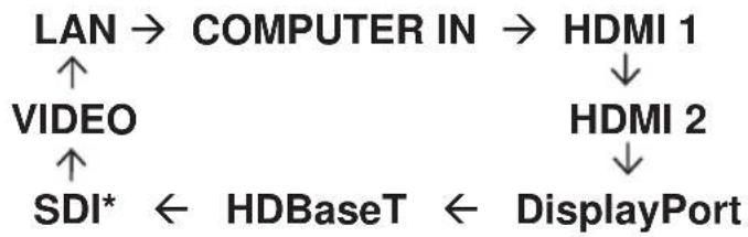
flowchart
graph TD
    A["LAN"] --> B["COMPUTER IN"]
    B --> C["HDMI 1"]
    C --> D["HDMI 2"]
    D --> E["DisplayPort"]
    F["VIDEO"] --> G["SDI*"]
    G --> H["HDBaseT"]
    H --> I["←"]
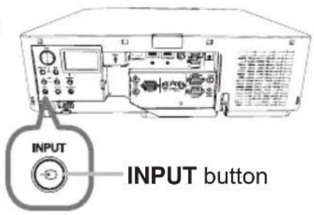
text_image
INPUT INPUT buttonNOTE • If you have set SKIP to some ports from SOURCE SKIP in the OPTION menu, the input from the ports cannot be selected (87).
- While ON is selected for AUTO SEARCH item in OPTION menu, the projector keeps checking the ports in the above order repeatedly until an input signal is detected (87).
1. Press COMPUTER 1, VIDEO, LAN, HDMI 1 / 2, DisplayPort, HDBaseT or SDI button on the remote control.
The port corresponding to each button is selected as below.
| Button Ports | |
| COMPUTER 1 COMPUTER IN | |
| COMPUTER 2 - | |
| VIDEO VIDEO | |
| LAN LAN | |
| USB TYPE A - | |
| USB TYPE B - | |
| HDMI 1 HDMI 1 | |
| HDMI 2 HDMI 2 | |
| DisplayPort DisplayPort | |
| HDBaseT HDBaseT | |
| SDI SDI* | |
| DIGITAL - | |
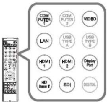
text_image
COM PUTER 1 COM PUTER 2 VIDEO LAN USB TYPE A USB TYPE B HDMI 1 HDMI 2 Display Port HD Base T SDI DIGITALButtons for input ports
NOTE • While ON is selected for AUTO SEARCH item in the OPTION menu, the projector keeps checking every port sequentially till an input signal is detected (87).
* LWU720i/LHD720i only
Selecting an aspect ratio
- Press the ASPECT button on the remote control. Each time you press the button, the projector switches the mode for aspect ratio in sequence.
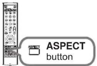
text_image
ASPECT buttonFor a computer signal
NORMAL → 4:3 → 16:9 → 16:10 → ZOOM → NATIVE
For HDMITM, HDBaseT™, and DisplayPort signals
NORMAL → 4:3 → 16:9 → 16:10 → 14:9 → ZOOM → NATIVE
For a video signal
4:3 → 16:9 → 16:10 → 14:9 → ZOOM → NATIVE
○ For an SDI signal (LWU720i/LHD720i only)
LWU720i : NORMAL → 4:3 → 16:9 → 16:10 → ZOOM → NATIVE
LHD720i : NORMAL → 4:3 → 16:9 → ZOOM → NATIVE
For an input signal from the LAN port, or if there is no signal
LWU720i/LWU620i: 16:10 (fixed)
LHD720i: 16:9 (fixed)
NOTE • The ASPECT button does not work when no proper signal is input. • NORMAL mode keeps the original aspect ratio setting.
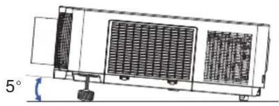
Adjusting the projector's elevator
Increasing or shortening the length of the elevator feet shifts the projection position and the projection angle.
Turn the elevator feet each to adjust their length.
natural_image
Technical line drawing of a rectangular industrial machine with internal grating and mounting base (no text or symbols)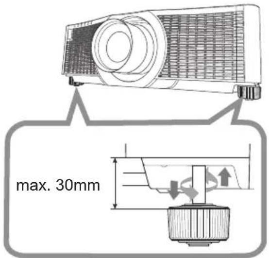
text_image
max. 30mm⚠ WARNING ▶ Do not lengthen the elevator feet exceeding 30 mm. The foot lengthened exceeding the limit may come off and drop the projector down, and result in an injury or damaging the projector.
⚠ CAUTION ▶ Do not place the projector with an inclination exceeding 5 degrees. The projector leaned exceeding the limit could cause malfunction and shorten the life of the projector.
Installation angle
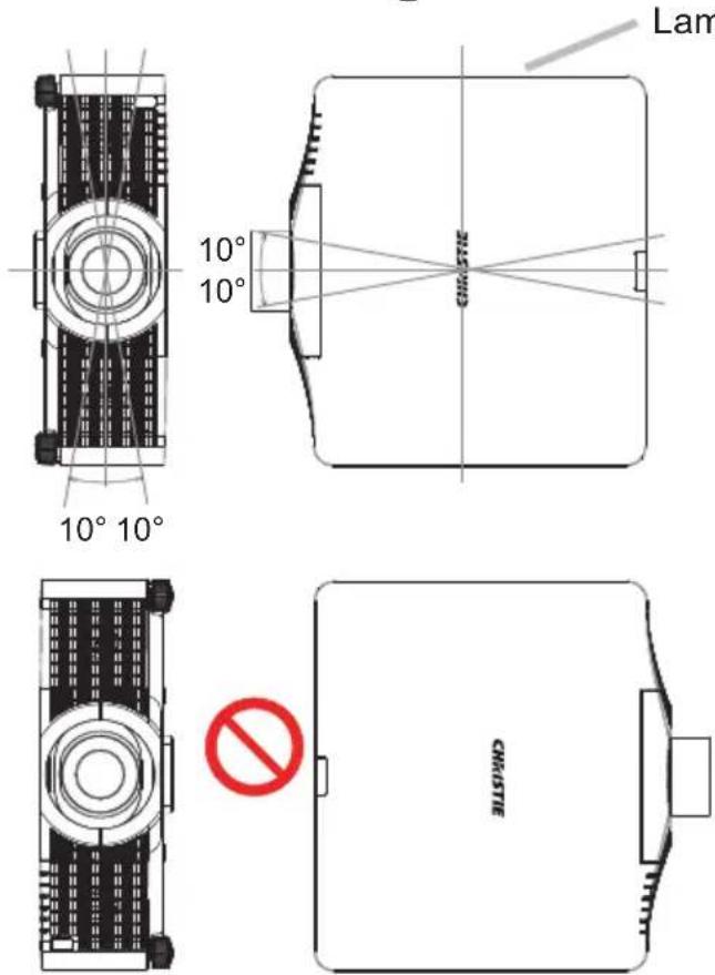
text_image
10° 10° 10° 10° Lam CHISTIEVertical and horizontal direction in portrait mode
The projector may be installed at horizontal angle of ±10^ .
The projector may be installed at vertical angle of ±10^ .
NOTE • The lamp side of the projector must face upward for vertical installations.
- If Other Error has occurred, check the installation. Install the projector correctly and restart it.
- When using portrait mode, the service life of a lamp becomes shorter.
Adjusting the lens
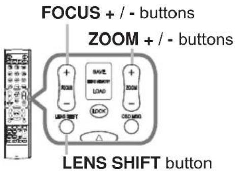
Adjusting the zoom and focus
The ZOOM or FOCUS dialog appears when you press any of the buttons from ZOOM, ZOOM -, ZOOM +, FOCUS + and FOCUS -.
- Use the ZOOM + / - buttons on the remote control or ZOOM button and ◀/▶ cursor buttons on the projector to adjust the screen size.
- Use the FOCUS + / - buttons to focus the picture.
NOTE • The projector may ignore the operation by other buttons while the lens is moving.
Adjusting the lens position
Press the LENS SHIFT button. The LENS SHIFT dialog appears. Using the ▲/▼/◄/► buttons while the dialog is displayed shifts the lens. Generally, better image quality can be got when the lens is set to the center.
Press the LENS SHIFT button again to exit the LENS SHIFT function.
CENTERING
Press the ENTER or INPUT button while the dialog is displayed to execute the CENTERING feature, which adjusts the lens to the center. A message dialog is displayed for confirmation. Pressing the ▶ button performs CENTERING. You can also perform CENTERING in the standby mode by pressing the FUNCTION and LENS SHIFT buttons on the control panel for three seconds at the same time.
text_image
FOCUS + / - buttons ZOOM + / - buttons + SAVE + + ZOOM + LOAD + LOCK + LINK SHIFT COLD MANGO LENS SHIFT button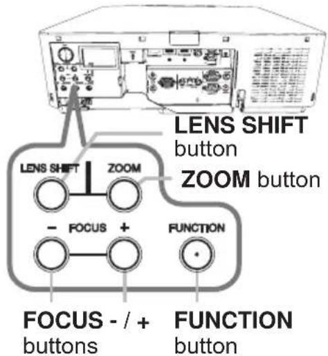
text_image
LENS SHIFT button ZOOM button LENS SHIFT ZOOM - FOCUS + FUNCTION FOCUS - / + buttons FUNCTION button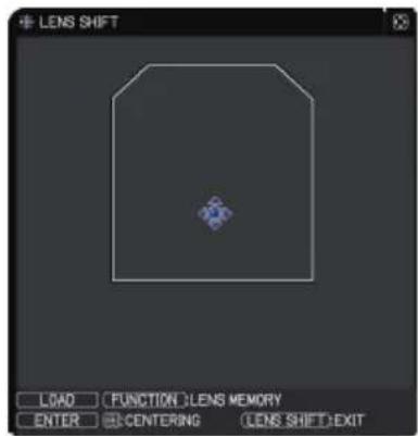
text_image
LENS SHIFT LOAD FUNCTION:LENS MEMORY ENTER CENTERING LENS SHIFT:EXIT⚠️ CAUTION ▶ Do not put your fingers or any other things around the lens. The moving lens could catch them in the space around the lens and result in an injury.
NOTE • While the lens is moving to the center, the menu disappears and an hourglass icon appears on the screen. CENTERING may take some time till the lens reaches the center.
- The projector may ignore operation by buttons while moving the lens.
- The CENTERING feature while the projector is in the standby mode is disabled if the STANDBY MODE item of SETUP menu is set to POWER SAVE. Perform CENTERING before the projector's power is turned off, or set the STANDBY MODE to NORMAL.
- The adjustable range of LENS SHIFT varies depending on the lens unit mounted on the projector to maintain picture quality. Therefore, LENS SHIFT adjustment may not reach the end of the indicator in the dialog. This is not a failure.
Adjusting the lens (continued)
Lens memory
This projector is equipped with memory functions for the lens adjustments (LENS SHIFT and LENS TYPE). Up to three sets of adjustments can be stored.
To use the lens memory feature, press the LOAD, SAVE or FUNCTION button while the LENS SHIFT dialog is displayed. Then the LENS MEMORY dialog appears. The current lens adjustments are displayed on the "CURRENT" line. The adjustments already stored in the lens memory are displayed on the lines of SAVE and LOAD-1 to 3.
text_image
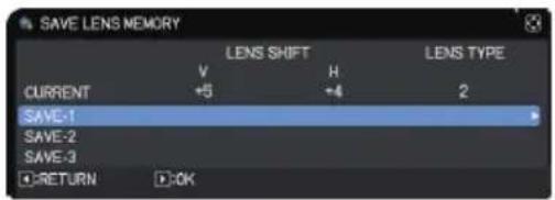
FUNCTION button LENS MEMORY button○ SAVE:
To store the current lens adjustments, select one of the "SAVE" options numbered 1 to 3 (number of the lens memory) and press the ▶ or ENTER button.
Remember that the current data being stored of a memory is lost by saving new data into the memory.
text_image
SAVE LENS MEMORY LENS SHIFT LENS TYPE V H 2 CURRENT +5 +4 SAVE-1 SAVE-2 SAVE-3 RETURN OK○ LOAD:
To recall stored adjustments, select one of the "LOAD" options numbered 1 to 3 (number of the lens memory) and press the ▶ or ENTER button.
Remember that the current adjusted condition is lost by loading data. If you want to keep the current adjustment, save it before performing a LOAD function.
○ CLEAR LENS MEMORY:
To clear the adjustment stored in a lens memory, select CLEAR LENS MEMORY and press the ▶ or ENTER button. The CLEAR LENS MEMORY dialog is displayed. Select the number of the lens memory to be cleared using the ▲/▼ buttons and press the ▶ button. A message dialog is displayed for confirmation. Press the ▶ button again to clear the lens memory.
NOTE • The projector may ignore the operation by buttons while moving the lens.
- You can perform the LOAD function using LENS MEMORY button.
Using the automatic adjustment feature
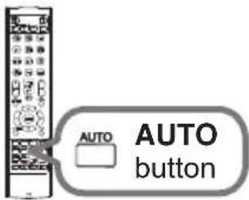
- Press AUTO button on the remote control. Pressing this button performs the following.
○ For a computer signal
The vertical position, the horizontal position and the horizontal phase are automatically adjusted.
Make sure that the application window is set to its maximum size prior to attempting to use this feature. A dark picture may still be incorrectly adjusted. Use a bright picture when adjusting.
text_image
AUTO AUTO button○ For a video signal
The video format best suited for the respective input signal is selected automatically. This function is available only when the AUTO is selected for the VIDEO FORMAT item in the INPUT menu (70). The vertical position and horizontal position are automatically set to the default.
○ For a component video signal
The vertical position and horizontal position are automatically set to the default. The horizontal phase is automatically adjusted.
NOTE • The automatic adjustment operation requires approximately 10 seconds. It may not function correctly with some input.
- When this function is performed for a video signal, an extra line may appear outside a picture.
- When this function is performed for a computer signal, a black frame may be displayed on the edge of the screen, depending on the computer model.
- The items adjusted by this function may vary when the FINE or DISABLE is selected for the AUTO IMAGE ADJUST item of the SERVICE item in the OPTION menu (94).
Operating
Correcting the distortion
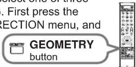
To correct the distortion of projected screen, you can select one of three options, KEYSTONE, 3D KEYSTONE, and WARPING. First press the GEOMETRY button to display the GEOMETRY CORRECTION menu, and
point at one of the items with the ▲/▼ buttons.
KEYSTONE: Adjust the vertical and horizontal keystone.
3D KEYSTONE: Adjust each of the screen corners and sides to correct the distortion.
WARPING: Project an image on several types of screen.
text_image
. First press the RECTION menu, and GEOMETRY button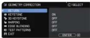
text_image
GEOMETRY CORRECTION RETURN □ KEYSTONE □ 3D KEYSTONE □ VARPING □ EDGE BLENDING □ TEST PATTERNS □ EXIT ON OFF OFF OFF OFF SELECT ENTERUse Keystone/3D Keystone/Warping for adjustment. When one is selected, other items are not available.
Complete the following procedure for the item you selected.
NOTE • The menu or dialog automatically disappears after several seconds of inactivity. Press the GEOMETRY button again, or point the cursor at EXIT in the dialog and press the ▶ or ENTER button to end the operation and close the menu or dialog.
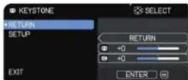
○ KEYSTONE:
When KEYSTONE is pointed at, pressing the ▶ or ENTER button displays the KEYSTONE dialog.
text_image
KEYSTONE RETURN SETUP EXIT SELECT RETURN +0 +0 ENTER-
Select the vertical or horizontal keystone (W) with the ▲/▼ buttons.
-
Use the ◀/▶ buttons to adjust the keystone distortion.
NOTE • When the zoom adjustment is set to the TELE (telephoto focus), this function may be excessive. This function should be used when the zoom adjustment is set to the full WIDE (wide-angle focus).
- When the horizontal lens shift is not set to the center, this function may not work correctly.
- Point at RETURN in the dialog with the ▲/▼ buttons and press ◀ or ENTER button to return to the GEOMETRY CORRECTION menu.
Correcting the distortion (continued)
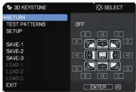
3D KEYSTONE:
When 3D KEYSTONE is pointed at, pressing the ▶ or ENTER button displays the 3D KEYSTONE dialog.
This projector is equipped with a test pattern for 3D KEYSTONE. Select TEST PATTERNS with the ▲/▼ buttons, then press the ◀/▶ buttons to switch on and off.
text_image
3D KEYSTONE RETURN TEST PATTERNS SETUP SAVE-1 SAVE-2 SAVE-3 LOAD-1 LOAD-2 LOAD-3 EXIT SELECT OFF 0 +0 0 0 + - 0 - + - 0 + - 0 + - 0 + - ENTER- Select SETUP with the ▲/▼ buttons and press the▶ or ENTER button.
- Select one of the corners or sides to be adjusted with the ▲/▼/◄/► buttons and press the ENTER or INPUT button.
-
Adjust the selected part as below.
-
To adjust a corner, use the ▲/▼/◄/► buttons to adjust the position of the corner.
- To adjust the upper or lower side, use the ▲/▼ buttons to adjust the distortion of the side.
- To adjust the left or right side, use the ◀/▶ buttons to adjust the distortion of the side.
- To adjust another corner or side, press the ENTER or INPUT button and follow the procedure from step 2.
(continued on next page)
Operating
Correcting the distortion (continued)
- This projector is equipped with a memory feature for 3D KEYSTONE adjustment. Up to three sets of adjustments can be stored.
- SAVE:
To store the current 3D KEYSTONE adjustment, select one of the "SAVE" options numbered 1 to 3 (number of the memory) with the ▲/▼ buttons and press the ▶, ENTER or INPUT button.
The current data being stored is lost by saving new data.
- LOAD:
To recall stored adjustments, select one of the "LOAD" options numbered 1 to 3 (number of the memory) with the ▲/▼ buttons and press the ▶, ENTER or INPUT button.
The current adjusted condition is lost by loading data. If you want to keep the current adjustment, save it before performing a LOAD function.
NOTE • The LOAD functions whose linked memories have no data are skipped. • There may be some noise and the screen may flicker for a moment when loading data. This is not malfunction.
○ WARPING:
Projection on several types of screen can be performed by WARPING function. This function is operated by using dedicated PC tool, "Warping Tool".
PC and projector are required to be connected with LAN cable to use this function.
You can get the PC tool from the following URL.
http://www.christiedigital.com
Refer to Application Manual for operations.
Using the EDGE BLENDING features
1. Mode (Manual/Camera)
OFF: Disables the Blending function.
Manual: Allows you to adjust Blending Region or Blending Level by using menu.
Camera: Allows you to perform automatic adjustment by using Camera in Projector Blending Tool.
- HDCR LiteLoc is not selectable when Blending is set to other than OFF.
- ECO MODE is not selectable when Blending is set to other than OFF.
- Keystone/3D Keystone/Warping are not selectable when Camera is selected in Blending.
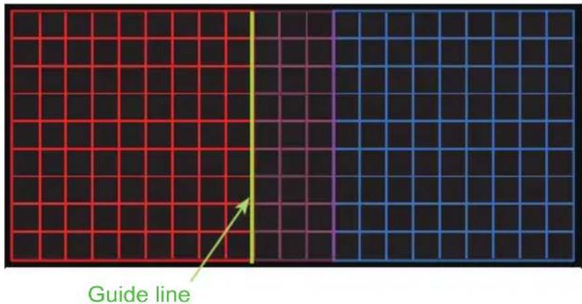
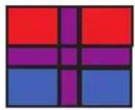
2. Blending Region
2.1 Specifying Blending Region
Select one of the four sides with ▲/▼/◄/► buttons and press ENTER or INPUT button. Blending Region can be specified for left and right sides with ◀/► buttons and for top and bottom sides with ▲/▼ buttons.
Specify Blending Region for each projector.
Adjust them referring to the guide displayed during the adjustment of Blending Region.
* The minimum value of Blending Region is 200 dots.
text_image
Guide line(continued on next page)
Operating
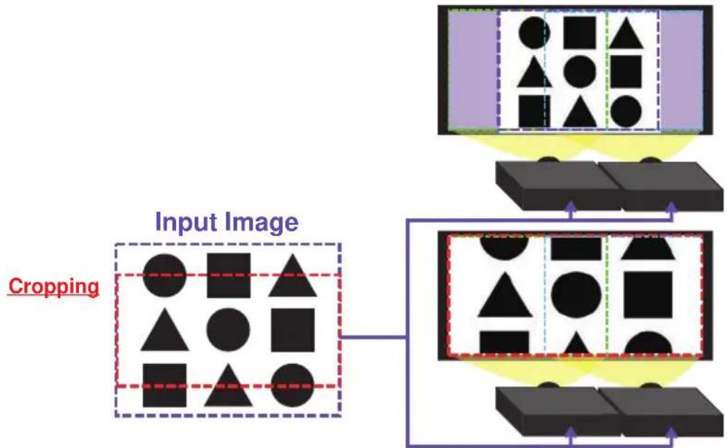
3. Cropping
When inputting the same image to each projector, The cropping function enables two projectors to cut out a part of input image and display one image on a large screen. The following patterns are supported.
2 × 1

1×2

2 × 2
3.1 Displaying Cropping Menu
Select CROPPING with ▲/▼ buttons and press ▶, ENTER or INPUT button to display Cropping Menu.
3.2 Setting Cropping
Select MODE with ▲/▼ buttons and select ON with ◀/▶ buttons.
The input image is automatically cut out according to the settings of Blending Region.
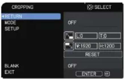
text_image
CROPPING RETURN MODE SETUP OFF L:0 T:0 V:1920 H:1200 RESET OFF ENTER(continued on next page)
3.3 Adjusting Cropping Area
Adjust the Cropping Area when cutting out a part of input image.
Select SETUP with ▲/▼ buttons and press ▶, ENTER or INPUT button.
* MODE is set to [OFF] temporarily and the guide of the Cropping Area is displayed.
Select [LT]/[WH] with ▲/▼ buttons and press the ENTER or INPUT button.
Move the guide display with ▲/▼/◄/► buttons to select the region of the screen to be cut out.
Press the ENTER or INPUT button and then press ◀ button to select SETUP, and MODE switches to ON automatically.
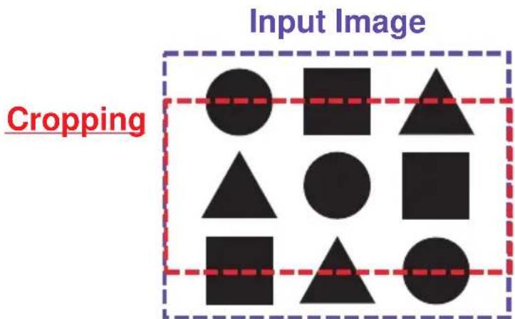
text_image
Input Image Cropping3.4 Adjust Cropping Area of the other projector.
Set the Cropping Area of the other projector with the same value as one projector.
The input image is automatically cut out according to the settings of the Blending Region.
* To keep input image from not being seen while setting up, set BLANK to ON.
flowchart
graph TD
    A["Input Image"] --> B["Cropping"]
    B --> C["Output Image"]
    style A fill:#f9f,stroke:#333
    style C fill:#bbf,stroke:#333
(continued on next page)
Operating
- Selecting Blending Level
Select the BLENDING LEVEL with ▲/▼ buttons.
[1-25] can be selected with ◀/▶ buttons.
Adjust the brightness of the Blending Region according to the settings.
- Dimming Level
Adjusts the brightness of the projectors which are using Blending.
Using the ◀/▶ buttons to adjust the dimming level.
- WHITE BALANCE
Adjusts the white balance of the whole screen.
6.1. OFFSET
Changes the color intensity on the whole tones.
6.2. GAIN
Mainly affects color intensity on the brighter tones.
- BLACK LEVEL
Adjusts black color level of the projectors which are using Blending.
Adjusts the adjustment value of R/G/B at the same time when W is selected.
When each of R/G/B is selected, the adjustment value of R/G/B can be adjusted respectively.
NOTE • The positional deviation of the screen may occur after installing the projector over time. Perform the screen adjustment again to correct the positional deviation.
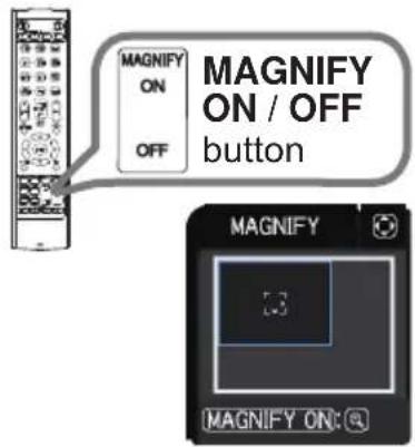
Using the magnify feature
1. Press the MAGNIFY ON button on the remote control.
The picture is magnified, and the MAGNIFY dialog appears on the screen. When the MAGNIFY ON button is pressed for the first time after the projector is turned on, the picture is zoomed by 1.5 times. On the dialog, triangle marks to show each direction are displayed.
text_image
MAGNIFY ON / OFF button MAGNIFY 13 MAGNIFY ON: ©2. The display magnification of the projector switches with every press of the MAGNIFY ON button.
For computer signals, HDMI ^TM (RGB) signals, HDBaseT ^TM signals, DisplayPort signals, input signals from the LAN port
1.5 times → 2 times → 3 times → 4 times → 1 time
For video signals, DisplayPort signals, HDBaseT signals, SDI signals, or HDMI ^TM signals
1.5 times → 2 times → 1 time
- While the triangles are displayed on the dialog, use the ▲/▼/◄/► cursor buttons to shift the magnifying area.
- Press the MAGNIFY OFF button on the remote control to exit magnification.
NOTE • The MAGNIFY dialog automatically disappears in several seconds with no operation. The dialog appears again if the MAGNIFY ON button is pressed when the dialog has automatically disappeared.
- The magnification is automatically disabled when the displaying signal or its display condition is changed.
- While the magnification is active, the keystone distortion condition may vary. It is restored when the magnification is disabled.
- Some horizontal stripes might be visible on the image while magnification is active.
• This function is not available in the following cases:
- A sync signal in the range not supported is input.
- There is no input signal.
- A sync signal in the range not supported is input. - There is no input signal.
Temporarily freezing the screen
- Press the FREEZE button on the remote control. The "FREEZE" indication appears on the screen (however, the indication does not appear when the OFF is selected for the OSD MESSAGE item in the SETUP (79), and the projector goes into the FREEZE mode, which the picture is frozen.

text_image
FREEZE FREEZE buttonTo exit the FREEZE mode and restore the screen to normal, press the FREEZE button again.
NOTE • The projector automatically exits from the FREEZE mode when some control buttons are pressed.
- If the projector continues projecting a still image for a long time, the LCD panel might possibly be burned in. Do not leave the projector in the FREEZE mode for too long.
- Images might appear degraded when this function is operated, but it is not a malfunction.
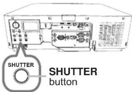
Temporarily shading the screen
- Press the SHUTTER button on the control panel. The mechanical shutter closes and the screen turns to black. The SHUTTER indicator on the projector blinks in yellow while the shutter is closed.
To open the shutter and restore the screen, press the SHUTTER button again.
text_image
SHUTTER SHUTTER button⚠️CAUTION ▶ If you want a blank screen while the projector's lamp is on, use the shutter function above or the AV MUTE function (37). Any other action may cause the damage on the projector.
NOTE • The projector turns off automatically when the time set up by the SHUTTER TIMER passes (88).
- When turning off the power by the normal procedure, the shutter opens automatically. If AC power supply is disconnected while opening or closing the shutter, the moving of the shutter stops. However, the next time the projector is turned on, the shutter opens again automatically.
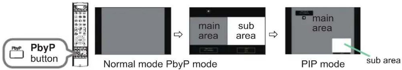
PbyP (Picture by Picture) / PIP (Picture in Picture)
The PbyP / PIP is a function for displaying two different picture signals on a screen that is separated into main and sub areas for each signal.
flowchart
graph LR
    A["PbyP button"] --> B["Normal mode PbyP mode"]
    B --> C["PIP mode"]
    C --> D["main area"]
    C --> E["sub area"]
Press the PbyP button on the remote control. This acactivates the PbyP mode. Then, press the PbyP button again. The projector goes into PIP mode. The screen displayed before the PbyP button was pressed is displayed as the main area. Most of operations are effective for the main area only. Only outputs the audio input signal paired with the picture input signal for the main area. To quit the PIP mode, press the PbyP button again.
NOTE • If the LAN port is selected when the PbyP button is pressed, input from other port is displayed on the main area.
- When in the PbyP / PIP mode, use the MENU button on the remote control or ▲/▼ buttons on the control panel to display the OSD menu.
- Some functions that cannot be used when in the PbyP / PIP mode.
- A message is displayed when buttons that cannot be used are pressed (118). However, messages are not displayed for some unusable buttons.
- The functions on the OSD menu that cannot be used are displayed in gray and cannot be selected.
(continued on next page)
Operating
PbyP (Picture by Picture) / PIP (Picture in Picture) (continued)
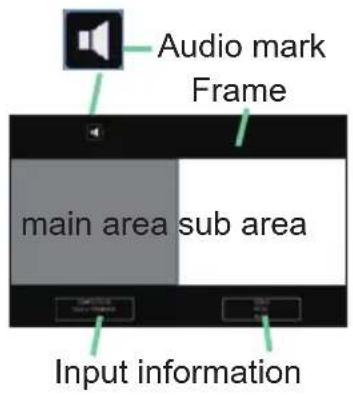
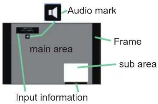
○ Setting information
The setting information appears for several seconds when the PbyP / PIP function is started. Displays the input information for each area. A frame around the main area and an audio mark indicating the audio output are also displayed. The information can be redisplayed with the ◀/▶ buttons after it has been erased.
text_image
Audio mark Frame main area sub area Input informationPbyP mode
text_image
Audio mark Frame main area sub area Input informationPIP mode
○ Changing the main area
The position of the main area can be toggled with the ◀/▶ buttons when the setting information is displayed on the screen. The frame and the audio mark move together with it.
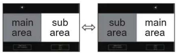
text_image
main area sub area ↔ sub area main areaPbyP mode
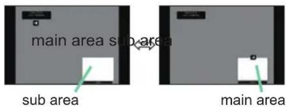
text_image
main area sub area sub area main areaPIP mode
(continued on next page)
PbyP (Picture by Picture) / PIP (Picture in Picture) (continued)
○ Changing the picture input signal
Press any button to select an input port on the remote control or press the INPUT button on the control panel. A dialog box to select the input signal for the main area is displayed. Choose a signal using the ▲/▼ buttons. To change the signal in the sub area, switch temporarily across to the main area with the ◀/► buttons.
Displaying the same signal on the both areas is not allowed. Refer to the table for details on available input signal combinations. Any combinations marked with "X" can not be selected.
| Sub areaMain area | COMPUTER IN | LAN | HDMI 1 | HDMI 2 | DisplayPort | HDBaseT | SDI (LWU720i/LHD720i) | VIDEO |
| COMPUTER IN | X X O | O O | O O | X | ||||
| LAN | X X X | X X | X X | X | ||||
| HDMI 1 | O X X | O X | X X | O | ||||
| HDMI 2 | O X O | X O | O O | O | ||||
| DisplayPort | O X X | O X | X X | O | ||||
| HDBaseT | O X X | O X | X X | O | ||||
| SDI (LWU720i/LHD720i) | O X X | O X | X X | O | ||||
| VIDEO | X X O | O O | O O | X |
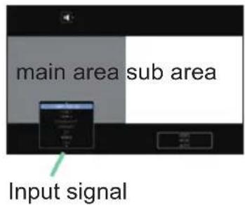
text_image
main area sub area Input signalPbyP mode
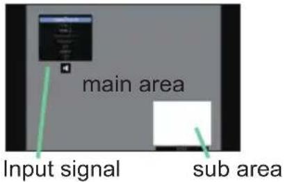
text_image
main area Input signal sub areaPIP mode
NOTE • The combined input signals marked with an "O" can be selected and displayed in the PbyP / PIP mode even when the port is set to SKIP with the SOURCE SKIP on the OPTION menu (87).
(continued on next page)
Operating
PbyP (Picture by Picture) / PIP (Picture in Picture) (continued)
○ PbyP / PIP SWAP function
Press the MY BUTTON assigned the PbyP / PIP SWAP (89). The position of the area is exchanged without any setting change.
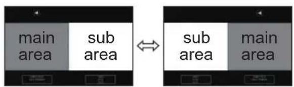
flowchart
graph LR
    A["main area"] --> B["sub area"]
    C["↔"] --> D["sub area"]
    E["main area"]
PbyP mode PIP mode
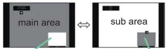
text_image
main area sub areasub area
main area
NOTE • For some signals, it may not be displayed correctly in the PbyP / PIP mode, even if it can be displayed properly in the normal mode.
- PbyP/PinP is unavailable when MANUAL is selected in GEOMETRY CORRECTION > EDGE BLENDING > MODE.
○ Changing the size of main area in PbyP mode
Using ▲/▼ buttons on the remote control changes the size of main area in PbyP mode.
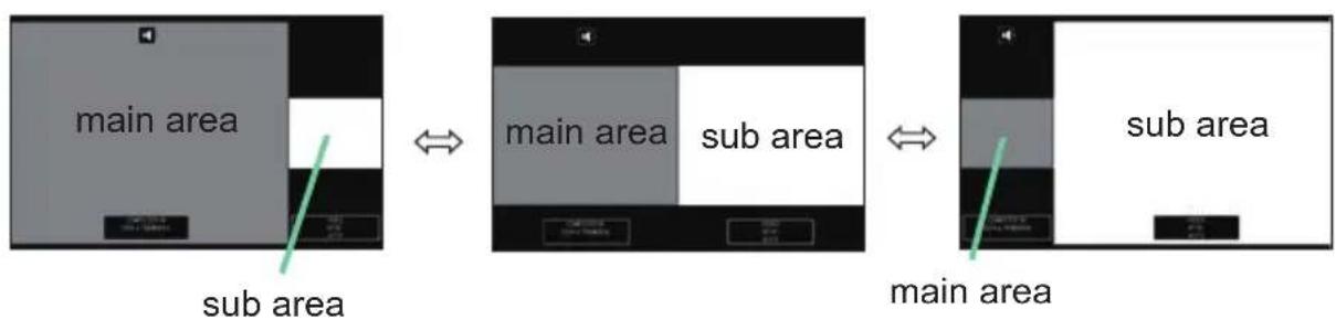
flowchart
graph LR
    A["main area"] --> B["sub area"]
    B <--> C["main area"]
    C --> D["sub area"]
    D <--> E["main area"]
○ Changing the position of sub area in PIP mode
- Select PIP POSITION in INPUT MENU (73).
- Using ▲/▼ buttons on the remote control changes the position of sub area in PIP mode.
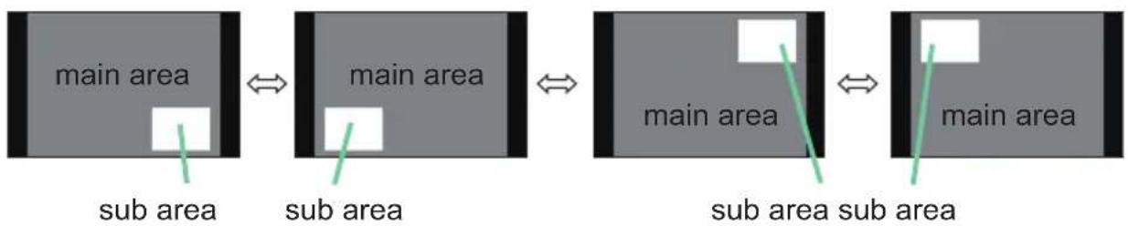
flowchart
graph LR
    A["main area"] --> B["sub area"]
    B --> C["main area"]
    C --> D["sub area"]
    D --> E["main area"]
    style A fill:#999
    style B fill:#ccc
    style C fill:#999
    style D fill:#ccc
    style E fill:#999
Using the menu function
This projector has the following menus:
IMAGE SETTINGS, SIZE AND POSITION, INPUT, SETUP, AUDIO,
MENU PREFERENCES, OPTION, NETWORK, SECURITY and EASY MENU.
EASY MENU consists of functions often used, and the other menus are classified into each purpose and brought together as the ADVANCED MENU.
Each menu is operated using the same methods. While the projector is displaying any menu, the MENU button on the projector works as the cursor buttons. The basic operations of these menus are as follows.
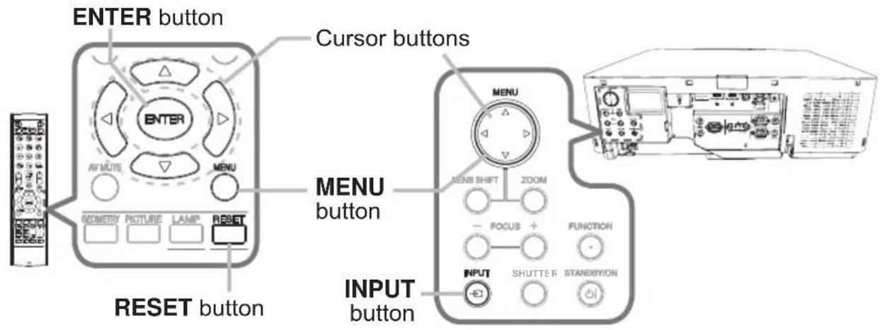
text_image
ENTER button AV MUTE MENU GEOMETRY PICTURE LAMP RESET RESET button Cursor buttons MENU button MENS SHIFT ZOOM - FOCUS + FUNCTION INPUT button SHUTTER STANDERION-
To start the MENU, press the MENU button. The MENU you last used (EASY or ADVANCED) appears. EASY MENU has priority to appear just after powered on.
-
In the EASY MENU
(1) Use the ▲/▼ cursor buttons to select an item to operate. To change it to the ADVANCED MENU, select the ADVANCED MENU.
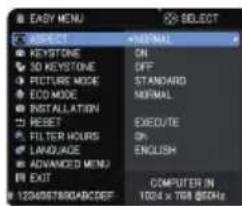
text_image
EASY MENU E SUBJECT KEYSTONE 50 KEYSTONE PICTURE MODE ECO MODE INSTALLATION RESET FILTER HOURS LANGUAGE ADVANCED MENU EXIT 120408788RABCDEF +INTERNAL ON OFF STANDARD NORMAL EXECUTE ENGLISH COMPUTER IN 1024 x 709 MHz(2) Use the ◀/▶ cursor buttons to operate the item.
In the ADVANCED MENU
(1) Use the ▲/▼ cursor buttons to select a menu. To change it to the EASY MENU, select the EASY MENU.
The items in the menu appear on the right side.
(2) Press the ▶ cursor button or ENTER button to move the cursor to the right side. Then use the
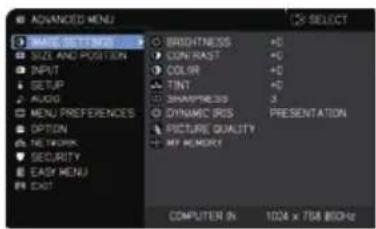
text_image
MUSIC SETTINGS SIZE AND POSITION INPUT SETUP AUDIO MENU PREFERENCES OPTION NETWORK SECURITY EASY MENU EXIT BRIGHTNESS +0 CUN RAST +0 COLOR +0 TINT +0 SHAKNESS 3 DYNAMIC PRESS PRESENTATION FIGURE QUALITY MY MEMORY COMPUTER IN 100 x 758 MHz▲/▼ cursor buttons to select an item to operate and press the ▶ cursor button or ENTER button to progress. The operation menu or dialog of the selected item appears.
(3) Use the buttons as instructed in the OSD to operate the item.
(continued on next page)
Operating
Using the menu function (continued)
- To close the MENU, press the MENU button again or select EXIT and press the ▶ cursor button or ENTER button. If you do not do anything, the dialog automatically disappears after about 30 seconds.
NOTE • Some functions cannot be performed when a certain input port is selected, or when a certain input signal is displayed.
- To reset the operation, press RESET button on the remote control during the operation. Note that some items (such as LANGUAGE, VOLUME) cannot be reset.
- In the ADVANCED MENU, when you want to return to the previous display, press the ◀ cursor button on the remote control.
Indication in OSD (On Screen Display)
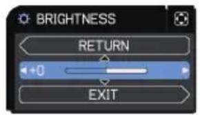
text_image
BRIGHTNESS RETURN +0 EXIT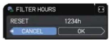
text_image
FILTER HOURS RESET 1234h CANCEL OK
text_image
MY MEMORY LOAD-4 TEMPORARY CONDITION ARE YOU SURE YOU WISH TO LOAD? NO YESThe meanings of the general words on the OSD are as follows.
| Indication Meaning | |
| EXIT | Closes the OSD menu. It is the same as pressing the MENU button. |
| RETURN Returns the menu to the previous menu. | |
| CANCEL or NO | Cancels the operation in the present menu and returns to the previous menu. |
| OK or YES | Executes the prepared function or shifts the menu to the next menu. |
Using the menu function (continued)
Menu items
The items contained in the menus are as below:
| Menu Items | |
| EASY MENU (60) | ASPECT, KEYSTONE, 3D KEYSTONE, PICTURE MODE, ECO MODE, INSTALLATION, RESET, FILTER HOURS, LANGUAGE, ADVANCED MENU, EXIT |
| IMAGE SETTINGS (62) | BRIGHTNESS, CONTRAST, COLOR, TINT, SHARPNESS, DYNAMIC IRIS, PICTURE QUALITY, MY MEMORY |
| SIZE AND POSITION (66) | ASPECT, OVER SCAN, V POSITION, H POSITION, H PHASE, H SIZE, AUTO IMAGE |
| INPUT (69) | PROGRESSIVE, VIDEO NR, COLOR SPACE,VIDEO FORMAT, DIGITAL RANGE, COMPUTER IN,FRAME LOCK, RESOLUTION, PbyP/PIP SETUP |
| SETUP (74) | GEOMETRY CORRECTION, LAMP & FILTER, HDCR LiteLoc,PICTURE POSITION, INSTALLATION, STANDBY MODE,COLOR UNIFORMITY, OSD MESSAGE |
| AUDIO (80) VOLUME, SPEAKER, AUDIO SOURCE | |
| MENU PREFERENCES (81) | LANGUAGE, MENU POSITION, BLANK, AUTO BLANK,START UP, My Screen, My Screen Lock, SOURCE NAME,TEMPLATE, Closed Caption C.C. |
| OPTION (87) | SOURCE SKIP, AUTO SEARCH, DIRECT POWER ON,AUTO POWER OFF, SHUTTER TIMER, MY BUTTON,SCHEDULE, SERVICE |
| NETWORK (101) | PROJECTOR NAME, WIRELESS SETUP, WIRED SETUP,NETWORK INFORMATION, SNTP SETUP, MY IMAGE,Third Party Control, PRESENTATION, WIRED NETWORK |
| SECURITY (102) | ENTER PASSWORD, SECURITY PASSWORD CHANGE,My Screen PASSWORD, PIN LOCK, TRANSITION DETECTOR,MY TEXT PASSWORD, MY TEXT DISPLAY, MY TEXT WRITING,SECURITY INDICATOR, STACK LOCK |
EASY MENU
Select an item form the EASY menu using the ▲/▼ cursor buttons. Then perform it according to the following table.
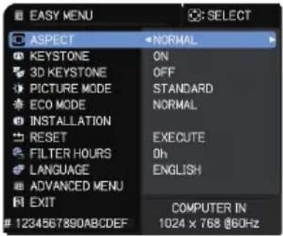
text_image
EASY MENU ASPECT NORMAL KEYSTONE ON 3D KEYSTONE OFF PICTURE MODE STANDARD ECO MODE NORMAL INSTALLATION EXECUTE RESET 0h FILTER HOURS LANGUAGE ENGLISH ADVANCED MENU COMPUTER IN EXIT 1234567890ABCDEF 1024 x 768 @60Hz| Item Description | |
| ASPECT | Using the ◀/► buttons switches the mode for aspect ratio.See the ASPECT item in SIZE AND POSITION menu (66). |
| KEYSTONE | Pressing the ► button displays the KEYSTONE dialog.See the KEYSTONE item in SETUP menu (74). |
| 3D KEYSTONE | Pressing the ► button displays the 3D KEYSTONE dialog.See the 3D KEYSTONE item in SETUP menu (74). |
| PICTURE MODE | Using the ◀/► buttons switches the picture mode.The picture modes are combinations of GAMMA and COLOR TEMP settings. Choose a suitable mode according to the projected source.STANDARD ⇔ NATURAL ⇔ CINEMA ⇔ DYNAMIC↓↓↓↓↓↓↓↓↓↓↓↓↓↓↓↓↓↓↓↓↓↓↓↓↓↓↓↓↓↓↓↓↓↓↓↓↓↓↓↓↓↓↓↓↓↓↓↓↓↓↓↓↓↓↓↓↓↓↓↓↓↓↓↓↓↓↓↓↓↓↓↓↓↓↓↓↓↓↓↓↓↓↓↓↓↓↓↓↓↓↓↓↓↓↓↓↓↓↓↓↑↓↓↓↓↓↓↓↓↓↓↓↓↓↓↓↓↓↓↓↓↓↓↓↓↓↓↓↓↓↓↓↓↓↓↓↓↓↓↓↓↓↓↓↓↓↓↓↓↓↓↓↓↓↓↓↓↓↓↓↓↓↓↓↓↓↓↓↓↓↓↓↓↓↓↓↓↓↓↓↓↓↓↓↓↓↓↓↓↓↓↓↓↓↓↓↓↓↓↓ ↓↓↓↓↓↓↓↓↓↓↓↓↓↓↓↓↓↓↓↓↓↓↓↓↓↓↓↓↓↓↓↓↓↓↓↓↓↓↓↓↓↓↓↓↓↓↓↓↓↓↓↓↓↓↓↓↓↓↓↓↓↓↓↓↓↓↓↓↓↓↓↓↓↓↓↓↓↓↓↓↓↓↓↓↓↓↓↓↓↓↓↓↓↓↓↓↓↓↓↓ |
(continued on next page)
| Item Description | |
| ECO MODE | Using the ◀/► buttons turns off/on the Eco mode.See the ECO MODE item in SETUP menu (75). |
| INSTALLATION | Pressing the ► button displays the INSTALLATION dialog.See the INSTALLATION item in SETUP menu (77). |
| RESET | Selecting this item resets all of the EASY MENU items except the FILTER HOURS and LANGUAGE.A dialog is displayed for confirmation. Selecting the OK using the ►button performs resetting. |
| FILTER HOURS | The usage time of the air filter is shown in the menu.Selecting this item resets the filter hours which counts usage time of the air filter.A dialog is displayed for confirmation. Selecting OK using the ►button initiates the reset.See the FILTER HOURS item in SETUP menu (76). |
| LANGUAGE | Using the ◀/► buttons changes the display language.See the LANGUAGE item in MENU PREFERENCES (81). |
| ADVANCED MENU | Press the ► or ENTER button to use the menu of IMAGE SETTINGS, SIZE AND POSITION, INPUT, SETUP, AUDIO, MENU PREFERENCES, OPTION, NETWORK or SECURITY. |
| EXIT Press the ◀ or ENTER button to close the OSD menu. | |
IMAGE SETTINGS menu
Select an item from the Image Settings menu using the ▲/▼ cursor buttons, and press the ▶ cursor button or ENTER button to execute the item. Then perform it according to the following table.
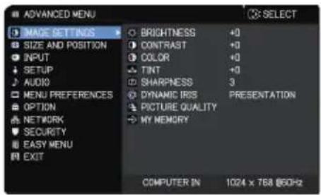
text_image
ADVANCED MENU MAGE SETTINGS SIZE AND POSITION INPUT SETUP AUDIO MENU PREFERENCES OPTION NETWORK SECURITY EASY MENU EXIT BRIGHTNESS +0 CONTRAST +0 COLOR +0 TINT +0 SHARPNESS 3 DYNAMIC IRIS PRESENTATION PICTURE QUALITY MY MEMORY COMPUTER IN 1024 x 768 @60Hz| Item Description | |
| BRIGHTNESS | Using the ◀/► buttons adjusts the brightness. Dark ⇔ Light |
| CONTRAST | Using the ◀/► buttons adjusts the contrast. Weak ⇔ Strong |
| COLOR | Using the ◀/► buttons adjusts the strength of whole color. Weak ⇔ Strong |
| TINT | Using the ◀/► buttons adjusts the tint. Reddish ⇔ Greenish |
| SHARPNESS | Using the ◀/► buttons adjusts the sharpness. Weak ⇔ Strong• There may be some noise and/or the screen may flicker for a moment when an adjustment is made. This is not a malfunction. |
| DYNAMIC IRIS | Using the ▲/▼ cursor buttons changes the dynamic iris control mode. PRESENTATION ⇔ THEATER ⇔ OFFPRESENTATION: The dynamic iris displays the best presentation image for both bright and dark scenes. THEATER: The dynamic iris displays the best theater image for both bright and dark scenes. OFF: The dynamic iris is always open.• The screen may flicker when the PRESENTATION or THEATER modes are selected. If this occurs, select OFF. |
(continued on next page)
| Item Description | |
| PICTURE QUALITY | Selecting this item displays the PICTURE QUALITY menu.Select an item using the ▲/▼ buttons, and press the ▶ button or the ENTER button on the remote control to execute the item. 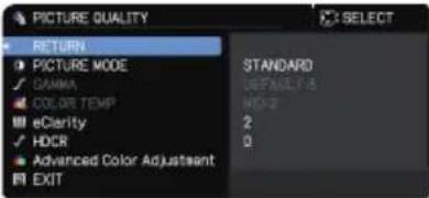 |
| PICTURE MODESTANDARD ⇔ NATURAL ⇔ CINEMA ⇔ DYNAMIC↓↓↓USER-3 BOARD(BLACK)↓↓↓USER-2 BOARD(GREEN)↓↓↓USER-1 ⇔ DICOM SIM. ⇔ DAYTIME ⇔ WHITEBOARDAfter selecting USER-1 / USER-2 / USER-3, the following features are adjustable.Gamma, Color Temp | |
| GAMMAThis feature is only available when USER-1 / USER-2 / USER-3 is selected.Using the ▲/▼ buttons switches the gamma mode.DEFAULT-1 ⇔ CUSTOM-1 ⇔ DEFAULT-2 ⇔ CUSTOM-2↓↓↓CUSTOM-8 DEFAULT-3↓↓↓DEFAULT-8 CUSTOM-3↓↓↓CUSTOM-7 DEFAULT-4↓↓↓DEFAULT-7 CUSTOM-4↓↓↓CUSTOM-6 ⇔ DEFAULT-6 ⇔ CUSTOM-5 ⇔ DEFAULT-5 | |
(continued on next page)
| Item Description | |
| PICTURE QUALITY (continued) | GAMMA (continued)Selecting a mode whose name includes CUSTOM and then pressing the ► button or the ENTER button displays a dialog to help you in adjusting the mode. This function is useful when you want to change the brightness of particular tones.Choose an item using the ◀/► buttons, and adjust the level using the ▲/▼ buttons.• Lines or other noise might appear on the screen when this function is operated, but it is not a malfunction. |
| COLOR TEMPThis feature is only available when USER-1 / USER-2 / USER-3 is selected.Using the ▲/▼ buttons switches the color temperature mode.HIGH ⇔ CUSTOM-1 ⇔ MID-1 ⇔ CUSTOM-2↑↓ ↑↓CUSTOM-7 MID-2↑↓ ↑↓HIGHBRIGHT-3 CUSTOM-3↑↓ ↑↓CUSTOM-6 LOW↑↓ ↑↓HIGHBRIGHT-2 ⇔ CUSTOM-5 ⇔ HIGHBRIGHT-1 ⇔ CUSTOM-4Selecting a mode whose name includes CUSTOM and then pressing the ► button or the ENTER button displays a dialog to aid you in adjusting the OFFSET and GAIN of the selected mode.OFFSET adjustments change the color intensity on the whole tones.GAIN adjustments mainly affect color intensity on the brighter tones.Choose an item using the ◀/► buttons, and adjust the level using the ▲/▼ buttons.• Lines or other noise might appear on the screen when this function is operated, but it is not a malfunction. | |
(continued on next page)
| Item Description | eClarityeClarity is a function to improve the legibility.Using the ◀/► buttons adjusts the sharpness.Weak ⇔ StrongThere may be some noise and/or the screen may flicker for a moment when an adjustment is made. This is not a malfunction.This function may not work properly when HDCR LiteLoc is enabled. |
| PICTURE QUALITY (continued) | HDCRA function to show a clear picture in a bright room.Using the ◀/► buttons adjusts the contrast.This function may not work properly when HDCR LiteLoc is enabled. |
| Advanced Color AdjustmentA function to adjust color phase, color saturation, and brightness respectively for red, yellow, green, cyan, blue, and magenta. | |
| MY MEMORY | This projector has four memories for adjustment data (for all the items of the IMAGE SETTINGS menu).Selecting a function using the ▲/▼ buttons and pressing the ► or ENTER button performs each function. SAVE-1, SAVE-2, SAVE-3, SAVE-4Performing a SAVE function saves the current adjustment data into the memory linked in the number included in the function's name.Remember that the current data being stored of a memory is lost by saving new data into the memory.LOAD-1, LOAD-2, LOAD-3, LOAD-4Performing a LOAD function loads the data from the memory linked in the number included in the function's name, and adjusts the picture automatically depending on the data.The LOAD functions whose linked memory has no data are skipped.Remember that the current adjusted condition is lost by loading data. To keep the current adjustment, save it before performing a LOAD function.There may be some noise and the screen may flicker for a moment when loading data. This is not malfunction.You can perform the LOAD function using MY BUTTON. See MY BUTTON item in OPTION menu (89). SAVE-1, SAVE-2, SAVE-3, SAVE-4Performing a SAVE function saves the current adjustment data into the memory linked in the number included in the function's name.Remember that the current data being stored of a memory is lost by saving new data into the memory.LOAD-1, LOAD-2, LOAD-3, LOAD-4Performing a LOAD function loads the data from the memory linked in the number included in the function's name, and adjusts the picture automatically depending on the data.The LOAD functions whose linked memory has no data are skipped.Remember that the current adjusted condition is lost by loading data. To keep the current adjustment, save it before performing a LOAD function.There may be some noise and the screen may flicker for a moment when loading data. This is not malfunction.You can perform the LOAD function using MY BUTTON. See MY BUTTON item in OPTION menu (89). |
SIZE AND POSITION menu
Select an item from the Size and Position menu using the ▲/▼ cursor buttons, and press the ▶ cursor button or ENTER button to execute the item. Then perform it according to the following table for selected port.
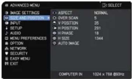
text_image
ADVANCED MENU IMAGE SETTINGS SIZE AND POSITION INPUT SETUP AUDIO MENU PREFERENCES OPTION NETWORK SECURITY EASY MENU EXIT ASPECT NORMAL OVER SCAN 5 V POSITION 35 H POSITION 291 H PHASE 18 H SIZE 1344 AUTO IMAGE COMPUTER IN 1024 x 768 @50Hz| Item Description | |
| ASPECT | Using the ▲/▼ buttons switches the mode for aspect ratio.For a computer signalNORMAL ⇔ 4:3 ⇔ 16:9 ⇔ 16:10 ⇔ ZOOM ⇔ NATIVEFor HDMITM, HDBaseTTM, and DisplayPort signalsNORMAL ⇔ 4:3 ⇔ 16:9 ⇔ 16:10 ⇔ 14:9 ⇔ ZOOM ⇔ NATIVEFor a video signal4:3 ⇔ 16:9 ⇔ 16:10 ⇔ 14:9 ⇔ ZOOM ⇔ NATIVEFor an SDI signal (LWU720i/LHD720i)LWU720i: NORMAL ⇔ 4:3 ⇔ 16:9 ⇔ 16:10 ⇔ ZOOM ⇔ NATIVELHD720i: NORMAL ⇔ 4:3 ⇔ 16:9 ⇔ ZOOM ⇔ NATIVEFor an input signal from the LAN port, or if there is no signalLWU720i/LWU620i: 16:10 (fixed)LHD720i: 16:9 (fixed)• The NORMAL mode keeps the original aspect ratio of the signal. |
(continued on next page)
| Item Description | |
| OVER SCAN | Using the ◀/► buttons adjusts the over-scan ratio.Small (It magnifies picture) ⇔ Large (It reduces picture)This item can't be selected for a computer signal of COMPUTER IN port and LAN port. |
| V POSITION | Using the ◀/► buttons adjusts the vertical position.Down ⇔ UpOver-adjusting the vertical position may cause noise to appear on the screen. If this occurs, reset the vertical position to the default setting. Pressing the RESET button when the V POSITION is selected resets the V POSITION to the default setting.When this function is performed on a video signal, the range of this adjustment depends on OVER SCAN (above) setting. You cannot adjust when OVER SCAN is set to 10.This function is unavailable for a signal from the LAN, HDMI 1 / 2, HDBaseT, DisplayPort, or SDI port. |
| H POSITION | Using the ◀/► buttons adjusts the horizontal position.Right ⇔ LeftOver-adjusting the horizontal position may cause noise to appear on the screen. If this occurs, reset the horizontal position to the default setting. Pressing the RESET button when the H POSITION is selected resets the H POSITION to the default setting.When this function is performed on a video signal, the range of this adjustment depends on OVER SCAN (above) setting. You cannot adjust when OVER SCAN is set to 10.This function is unavailable for a signal from the LAN, HDMI 1 / 2, HDBaseT, DisplayPort, or SDI port. |
(continued on next page)
| Item Description | |
| H PHASE | Using the ◀/► buttons adjusts the horizontal phase to eliminate flicker.Right ⇔ LeftThis item can be selected only for a computer signal or a component video signal. This function is unavailable for a signal from the LAN, HDMITM 1 / 2, HDBaseTTM, DisplayPort, or SDI port. |
| H SIZE | Using the ◀/► buttons adjusts the horizontal size.Small ⇔ LargeThis item can be selected only for a computer signal. This function is unavailable for a signal from the LAN, VIDEO, HDMI 1 / 2, HDBaseT, DisplayPort, or SDI port.When this adjustment is excessive, the picture may not be displayed correctly. If this occurs, reset the adjustment by pressing the RESET button on the remote control during this operation.Images might appear degraded when this function is operated, but it is not a malfunction. |
| AUTO IMAGE | Selecting this item performs the automatic adjustment feature.For a computer signalThe vertical position, the horizontal position and the horizontal phase are automatically adjusted.Make sure that the application window is set to its maximum size prior to attempting to use this feature. A dark picture may still be incorrectly adjusted. Use a bright picture when adjusting.For a video signalThe video format best suited for the respective input signal is selected automatically. This function is available only when the AUTO is selected for the VIDEO FORMAT item in the INPUT menu (70). The vertical position and horizontal position are automatically set to the default.The automatic adjustment operation requires approx. 10 seconds. Note that it may not function correctly with some input.When this function is performed for a video signal, an extra line may appear outside a picture.When this function is performed for a computer signal, a black frame may be displayed on the edge of the screen, depending on the computer model.The items adjusted by this function may vary when the FINE or DISABLE is selected for the AUTO IMAGE ADJUST item of the SERVICE item in the OPTION menu (94). |
INPUT menu
Select an item from the Input menu using the ▲/▼ cursor buttons, and press the ▶ cursor button or ENTER button to execute the item. Then perform it according to the following table.
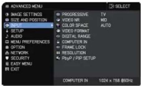
text_image
ADVANCED MENU IMAGE SETTINGS SIZE AND POSITION INPUT SETUP AUDIO MENU PREFERENCES OPTION NETWORK SECURITY EASY MENU EXIT PROGRESSIVE TV VIDEO NR MID COLOR SPACE AUTO VIDEO FORMAT DIGITAL RANGE COMPUTER IN FRAME LOCK RESOLUTION PbyP /PIP SETUP COMPUTER IN 1024 x 768 @5GHz| Item Description | |
| PROGRESSIVE | Using the ▲/▼ buttons switches the progress mode.TV ⇔ FILM ⇔ OFFThis function works only for a video signal, component video signal (of 480i@60 or 576i@50 or 1080i@50/60), an HDMITM signal (of 480i@60 or 576i@50 or 1080i@50/60) and HDBasetTM signal (of 480i@60 or 576i@50 or 1080i@50/60).When TV or FILM is selected, the screen image is sharp. FILM adapts to the 2-3 Pull-Down conversion system. But these may cause a certain defect (for example, jagged line) of the picture for a quick moving object. If this occurs, select OFF, even if the screen image loses sharpness. |
| VIDEO NR | Using the ▲/▼ buttons switches the noise reduction mode.HIGH ⇔ MID ⇔ LOWThis function works only for a video signal, component video signal (of 480i@60 or 576i@50 or 1080i@50/60), an HDMITM signal (of 480i@60 or 576i@50 or 1080i@50/60) and HDBasetTM signal (of 480i@6O or 576i@50 or 1080i@50/60). |
| COLOR SPACE | Using the ▲/▼ buttons switches the mode for color space.AUTO ⇔ RGB ⇔ SMPTE240 ⇔ REC709 ⇔ REC601This item can be selected only for a computer signal (except for signals from the LAN and HDBaset ports).The AUTO mode automatically selects the optimum mode.The AUTO operation may not work correctly at some signals. If this occurs, select a suitable mode except AUTO. |
(continued on next page)
| Item Description | |
| VIDEO FORMAT | The video format forVIDEOport can be set.Using the◄/► buttonsswitches the mode for video format. AUTO ⇔ NTSC ⇔ PAL ⇔ SECAMN-PAL ⇔ M-PAL ⇔ NTSC4.43◄This item is used only for a video signal from theVIDEOport.The AUTO mode automatically selects the optimum mode.The AUTO operation may not work well for some signals. If the picture becomes unstable (for example, an irregular picture, lack of color), select the mode according to the input signal. AUTO ⇔ NTSC ⇔ PAL ⇔ SECAMN-PAL ⇔ M-PAL ⇔ NTSC4.43◄This item is used only for a video signal from theVIDEOport.The AUTO mode automatically selects the optimum mode.The AUTO operation may not work well for some signals. If the picture becomes unstable (for example, an irregular picture, lack of color), select the mode according to the input signal. |
| DIGITAL RANGE | The digital range ofHDMI ^TM input signals from theHDMI 1/2,HDBaseT ^TM , DisplayPort, and SDIports can be set.LWU720i/LHD720iLWU620i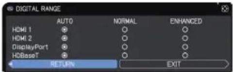 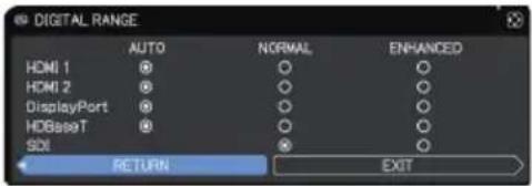 (1) Use the▲/▼buttons to select the port to be set.(2) Use the◄/►buttons to select the digital range.AUTO ⇔ NORMAL ⇔ ENHANCEDAUTO: automatically sets the optimum mode.NORMAL: sets the suitable mode for DVD signals. (16-235)ENHANCED: sets the suitable mode for computer signals. (0-255) ((1-254) for SDI)If the contrast of the screen image is too strong or weak, try finding a more suitable mode. (1) Use the▲/▼buttons to select the port to be set.(2) Use the◄/►buttons to select the digital range.AUTO ⇔ NORMAL ⇔ ENHANCEDAUTO: automatically sets the optimum mode.NORMAL: sets the suitable mode for DVD signals. (16-235)ENHANCED: sets the suitable mode for computer signals. (0-255) ((1-254) for SDI)If the contrast of the screen image is too strong or weak, try finding a more suitable mode. |
(continued on next page)
| Item Description | |
| COMPUTER IN | The computer input signal type for COMPUTER IN port can be set.Use the ◀/► buttons to select thecomputer input signal type. AUTO ⇔ SYNC ON G OFF 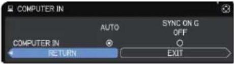 Selecting the AUTO mode, youcan input a sync on G signal or component video signal from the port.In the AUTO mode, the picture may be distorted with certain inputsignals. If this occurs, remove the signal connector so that no signalis received and select the SYNC ON G OFF, and then reconnect thesignal. Selecting the AUTO mode, youcan input a sync on G signal or component video signal from the port.In the AUTO mode, the picture may be distorted with certain inputsignals. If this occurs, remove the signal connector so that no signalis received and select the SYNC ON G OFF, and then reconnect thesignal. |
| FRAME LOCK | Set the frame lock function on/off for each port.LWU720i/LHD720iLWU620i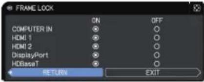 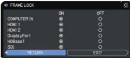 (1) Use the ▲/▼ buttons to select the input ports.(2) Use the ◀/► buttons to turn the frame lock function on/off.ON ⇔ OFFThis item can be performed only on a signal with a verticalfrequency of 49 to 51Hz, 59 to 61 Hz.When ON is selected, moving pictures are displayed more smoothly. (1) Use the ▲/▼ buttons to select the input ports.(2) Use the ◀/► buttons to turn the frame lock function on/off.ON ⇔ OFFThis item can be performed only on a signal with a verticalfrequency of 49 to 51Hz, 59 to 61 Hz.When ON is selected, moving pictures are displayed more smoothly. |
(continued on next page)
| Item Description | |
| RESOLUTION | The resolution for the COMPUTER IN input signal can be set on this projector.(1) In the INPUT menu select the RESOLUTION using the ▲/▼ buttons and press the ▶ button.The RESOLUTION menu is displayed.(2) In the RESOLUTION menu select the resolution you wish to display using the ▲/▼ buttons.Selecting AUTO SETUP sets a resolution appropriate to the input signal.(3) Pressing the ▶ or ENTER button when selecting a STANDARD resolution automatically adjusts the horizontal and vertical positions, clock phase and horizontal size.The INPUT INFORMATION dialog is displayed.(4) To set a custom resolution, use the ▲/▼ buttons to select the CUSTOM and the RESOLUTION CUSTOM box.Set the HORIZONTAL and VERTICAL resolutions using the ▲/▼/◄/► buttons.This function may not support all resolutions.(5) Move the cursor to OK on the screen and press the ▶ or ENTER button. The message "ARE YOU SURE YOU WISH TO CHANGE RESOLUTION?" appears. To save the setting, press the ▶ button.The horizontal and vertical positions, clock phase and horizontal size are automatically adjusted.The INPUT INFORMATION dialog is displayed.(6) To revert to the previous resolution without saving changes, move the cursor to CANCEL on screen and press the ◀ or ENTER button.The screen then returns to the RESOLUTION menu displaying the previous resolution.• For some pictures, this function may not work well. |
(continued on next page)
| Item Description | |
| PbyP / PIP SETUP | PIP POSITIONUsing ▲/▼ buttons on the remote control changes the position of sub area in PIP mode (56). |
| PbyP / PIP FRAME LOCKSelect the screen that enables FRAME LOCK function when using PbyP or PIP.LEFT / PRIMARY: Enables FRAME LOCK function for input on left screen of PbyP or on primary area of PIP.RIGHT / SECONDARY: Enables FRAME LOCK function for input on right screen of PbyP or on secondary area of PIP. | |
SETUP menu
Select an item from the Setup menu using the ▲/▼ cursor buttons, and press the ▶ cursor button or ENTER button to execute the item. Then perform it according to the following table.
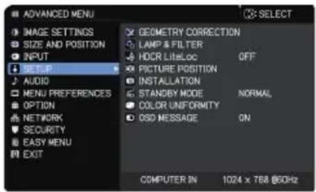
text_image
ADVANCED MENU IMAGE SETTINGS SIZE AND POSITION INPUT SETUP AUDIO MENU PREFERENCES OPTION NETWORK SECURITY EASY MENU EXIT GEOMETRY CORRECTION LAMP & FILTER HDRC LiteLoc OFF PICTURE POSITION INSTALLATION STANDBY MODE NORMAL, COLOR UNIFORMITY OSD MESSAGE ON COMPUTER IN 1024 x 768 @60Hz| Item Description | |
| GEOMETRY CORRECTION | KEYSTONESelecting this item displays the KEYSTONE dialog.For details, see KEYSTONE in Correcting the distortion(44).When the zoom adjustment is set to the TELE (telephoto focus), this function may be excessive. This function should be used when the zoom adjustment is set to the full WIDE (wide-angle focus).When the horizontal lens shift is not set to the center, this function may not work correctly.This function is unavailable when the screen is activated by 3D KEYSTONE (45), and WARPING (46). |
| 3D KEYSTONESelecting this item displays the 3D KEYSTONE dialog. For details, see 3D KEYSTONE in Correcting the distortion (45).This function is unavailable when the screen is activated by KEYSTONE (44), and WARPING (46). | |
| WARPINGSelecting this item displays the WARPING dialog. For details, see Application Manual of this feature.This function is unavailable when the screen is activated by KEYSTONE (44) and 3D KEYSTONE (45). | |
| EDGE BLENDINGSelecting this item displays the EDGE BLENDING dialog. For details, see EDGE BLENDING feature (47 ~ 50). | |
(continued on next page)
| Item Description | ||
| GEOMETRY CORRECTION (continued) | TEST PATTERNSSelect PATTERN with ▲/▼ buttons. Displayed pattern [Off/1/2/3/4/5/6] can be switched with ◀/► buttons.PATTERN 1: FramePATTERN 2: Red GridPATTERN 3: Green GridPATTERN 4: Blue GridPATTERN 5: Vertical 9 stepsPATTERN 6: Horizontal 9 stepsOFF: Displays the input signal. | 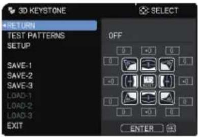 |
| LAMP & FILTER | Selecting this item displays the LAMP & FILTER menu.Select an item using the ▲/▼ buttons, and press the ► button or the ENTER button on the remote control to execute the item. | 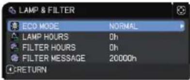 |
| ECO MODEUsing the ▲/▼ buttons switches the Eco mode.NORMAL ⇔ ECOWhen the item other than NORMAL is selected, acoustic noise and screen brightness are reduced. | ||
| LAMP HOURSThe lamp time is the usage time of the lamp, counted after the last resetting. It is shown in the LAMP & FILTER menu.Pressing the RESET button on the remote control or the ► button of the projector displays a dialog.To reset the lamp time, select the OK using the ► button.CANCEL ⇒ OKFor the lamp replacement, see the sectionReplacing the lamp(109).The lamp time can be checked also with the Status Monitor(31).The HDCR LiteLoc function does not work properly unless LAMP HOURS is initialized when replacing a lamp. | ||
(continued on next page)
| Item Description | |
| LAMP & FILTER(continued) | FILTER HOURSDisplays the usage time of the air filter, counted after the last resetting. It is shown in the LAMP & FILTER menu.Pressing the RESET button on the remote control or the ▶ button of the projector displays a dialog.To reset the filter hours, select the OK using the ▶ button.CANCEL ⇒ OKReset the filter hours only when you have cleaned or replaced the air filter, for a suitable indication about the air filter.For the air filter cleaning, see the section Cleaning and replacing the air filter (111).The filter hours can also be checked with the Status Monitor (31). |
| FILTER MESSAGEUse the ▲/▼ button to set the timer for notifying by the message when to replace the filter unit1000h ⇌ 2000h ⇌ 5000h ⇌ 10000h ⇌ 15000h ⇌ 20000h ⇌ 25000h ⇌ 30000h ⇌ OFFAfter choosing an item except OFF, the message “REMINDER *** HRS PASSED ....” appears after the timer reaches the interval time set by this feature.When the OFF is chosen, the message does not appear. Use this feature to keep the air filter clean, setting the suitable time according to your environment of this projector.Clean the filter periodically. If the air filter becomes to be blocked by dust or other matter, the internal temperature rises, which could cause malfunction, or reduce the lifetime of the projector.Be careful with the operating environment of the projector and the condition of the filter unit. | |
| HDCRLiteLoc | When this function is enabled, automatic image correction is performed to maintain visibility according to lamp deterioration.This function may not work properly when HDCR/eClarity is set to other than 0.This function does not work properly unless LAMP HOURS is initialized when replacing a lamp. |
(continued on next page)
| Item Description | |
| PICTURE POSITION | Using the ▲/▼/◄/► cursor buttons selects the required picture position.The PICTURE POSITION is not changed if any of the following cases apply.There is no non-display area (black display or background display) or it is not displayed on the screen.One of the following messages is displayed on the screen:"NO INPUT IS DETECTED""SYNC IS OUT OF RANGE""INVALID SCAN FREQ."The BLANK or TEMPLATE function is selected. |
| INSTALLATION | Pressing the ►button displays the dialog for changing the INSTALLATION setting.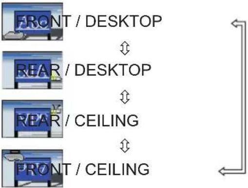 Use the ▲/▼ buttons to select the required setting on the INSTALLATION dialog, and press the ENTER button of the remote control or the INPUT button of the projector to execute.If TRANSITION DETECTOR is ON and the INSTALLATION status is changed, the TRANSITION DETECTOR ON alarm (105) is displayed when the projector is restarted. Use the ▲/▼ buttons to select the required setting on the INSTALLATION dialog, and press the ENTER button of the remote control or the INPUT button of the projector to execute.If TRANSITION DETECTOR is ON and the INSTALLATION status is changed, the TRANSITION DETECTOR ON alarm (105) is displayed when the projector is restarted. |
(continued on next page)
| Item Description | |
| STANDBY MODE | Using ▲/▼ buttons switches the standby mode setting between NORMAL and POWER SAVE.NORMAL ⇔ POWER SAVEWhen POWER SAVE is selected, the power consumption in the standby mode is lowered with some functional restriction as below:·When POWER SAVE is selected, the RS-232C communication control except to turn the projector on and the network function are disabled while the projector is in the standby mode. If the COMMUNICATION TYPE in the COMMUNICATION menu is set to NETWORK BRIDGE, all of the RS-232C commands are disabled (97).·This function is unavailable when NETWORK BRIDGE is selected for COMMUNICATION TYPE. (OPTION menu > SERVICE > COMMUNICATION)·This function is available only when OFF is selected for STACK MODE. (OPTION menu > SERVICE > COMMUNICATION > STACK)·When POWER SAVE is selected, AUDIO OUT STANDBY setting of AUDIO SOURCE (80) is invalid, and no signal is output from AUDIO OUT port in the standby mode.·When POWER SAVE is selected, STANDBY setting of MONITOR OUT is invalid, and no signal is output from MONITOR OUT port in the standby mode.·When POWER SAVE is selected, the CENTERING feature while the projector is in the standby mode is disabled.·When POWER SAVE is selected, the Status Monitor and its button operation are unavailable while the projector is in the standby mode.·When POWER SAVE is selected, the HDMI Link and HDBaseT functions are disabled while the projector is in the standby mode.·When POWER SAVE is selected, SCHEDULE function (Ex. POWER-ON) at STANDBY MODE will not be operated. |
| COLOR UNIFORMITY | Selects image level and region must be required corrected, and adjusts Color Balance.Divides the screen into nine regions and adjusts gain of R/G/B of each region. |
(continued on next page)
| Item Description | Using the ▲/▼ buttons turns on/off the message function.ON ⇔ OFF ⇔ HIDE ■OFF: The following message functions do not work."AUTO IN PROGRESS" while automatically adjusting"NO INPUT IS DETECTED""SYNC IS OUT OF RANGE""INVALID SCAN FREQ.""NOT AVAILABLE""Searching...." while searching for the input"Detecting...." while an input signal is detectedThe indication of the ZOOM displayed by changing*While operating from the remote control only.The indication of the FOCUS displayed by changingThe indication of the input signal displayed by changingThe indication of the aspect ratio displayed by changingThe indication of the PICTURE MODE displayed by changingThe indication of the DYNAMIC IRIS displayed by changingThe indication of the MY MEMORY displayed by changingThe indication of "FREEZE" and "II" while freezing the screen by pressing the FREEZE button.The indication of the TEMPLATE displayed by changing.The indication of the ECO MODE displayed by changing.■HIDE: All message functions does not work.The following buttons function:STANDBY, ONStatus Monitor can be operated.To change this function, follow the steps below.1. Press the OSD MSG button on the remote control for three seconds.2. The OSD is displayed.While this OSD is displayed, press the OSD MSG button again on the remote control.3. Toggle and change the function.ON ⇔ OFF ⇔ HIDE ■OFF: The following message functions do not work."AUTO IN PROGRESS" while automatically adjusting"NO INPUT IS DETECTED""SYNC IS OUT OF RANGE""INVALID SCAN FREQ.""NOT AVAILABLE""Searching...." while searching for the input"Detecting...." while an input signal is detectedThe indication of the ZOOM displayed by changing*While operating from the remote control only.The indication of the FOCUS displayed by changingThe indication of the input signal displayed by changingThe indication of the aspect ratio displayed by changingThe indication of the PICTURE MODE displayed by changingThe indication of the DYNAMIC IRIS displayed by changingThe indication of the MY MEMORY displayed by changingThe indication of "FREEZE" and "II" while freezing the screen by pressing the FREEZE button.The indication of the TEMPLATE displayed by changing.The indication of the ECO MODE displayed by changing.■HIDE: All message functions does not work.The following buttons function:STANDBY, ONStatus Monitor can be operated.To change this function, follow the steps below.1. Press the OSD MSG button on the remote control for three seconds.2. The OSD is displayed.While this OSD is displayed, press the OSD MSG button again on the remote control.3. Toggle and change the function.ON ⇔ OFF ⇔ HIDE |
| OSD MESSAGE |
AUDIO menu
Select an item from the Audio menu using the ▲/▼ cursor buttons, and press the ▶ cursor button or the ENTER button to execute the item. Then perform it according to the following table.
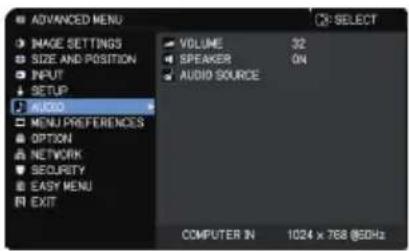
text_image
ADVANCED MENU IMAGE SETTINGS SIZE AND POSITION INPUT SETUP AUDIO MENU PREFERENCES OPTION NETWORK SECURITY EASY MENU EXIT VOLUME 32 SPEAKER 04 AUDIO SOURCE COMPUTER IN 1024 x 768 @5GHz| Item Description | |
| VOLUME | Using the ◀/► buttons adjusts the volume of the audio output.Low ⇔ High |
| SPEAKER | Using the ▲/▼ buttons turns on/off the built-in speaker.ON ⇔ OFFWhen OFF is selected, the built-in speaker does not work. |
| AUDIO SOURCE | While the image signal from the input port chosen in step (1) is projected, the audio signal from the input port selected in step (2) is output to both theAUDIO OUTport and built-in speaker of this projector. However, the built-in speaker does not work when SPEAKER is set to OFF.LWU720i/LHD720iLWU620i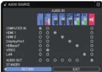 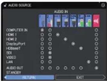 (1) Choose a picture input port using the ▲/▼ buttons.Choose AUDIO OUT STANDBY to select the sound output in the standby mode.(2) Select an audio input port or the mute icon using the ◀/► buttons.The icons indicate the following;No.1:AUDIO IN1port No.2:AUDIO IN2portNo.3:HDMI 1port No.4:HDMI 2portNo.5:DisplayPort No.6:HDBaseTportNo.7:LAN port※ : mutes the soundAudio input from port numbers 3 to 7 can only be selected by each of the picture input ports and AUDIO OUT STANDBY.Closed Caption C.C. is automatically activated when※ is selected and an input signal containing Closed Caption C.C. is received.This function is available only when the signal is NTSC forVIDEOorCOMPUTER IN, and when AUTO is selected for DISPLAY in the Closed Caption C.C. menu under the MENU PREFERENCES(86). (1) Choose a picture input port using the ▲/▼ buttons.Choose AUDIO OUT STANDBY to select the sound output in the standby mode.(2) Select an audio input port or the mute icon using the ◀/► buttons.The icons indicate the following;No.1:AUDIO IN1port No.2:AUDIO IN2portNo.3:HDMI 1port No.4:HDMI 2portNo.5:DisplayPort No.6:HDBaseTportNo.7:LAN port※ : mutes the soundAudio input from port numbers 3 to 7 can only be selected by each of the picture input ports and AUDIO OUT STANDBY.Closed Caption C.C. is automatically activated when※ is selected and an input signal containing Closed Caption C.C. is received.This function is available only when the signal is NTSC forVIDEOorCOMPUTER IN, and when AUTO is selected for DISPLAY in the Closed Caption C.C. menu under the MENU PREFERENCES(86). |
MENU PREFERENCES
Select an item from the Menu Preferences menu using the ▲/▼ cursor buttons, and press the ▶ cursor button or ENTER button to execute the item. Then perform it according to the following table.
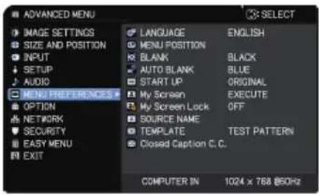
text_image
ADVANCED MENU IMAGE SETTINGS SIZE AND POSITION INPUT SETUP AUDIO MENU PREFERENCES OPTION NETWORK SECURITY EASY MENU EXIT LANGUAGE ENGLISH MENU POSITION BLANK BLACK AUTO BLANK BLUE START UP ORIGINAL My Screen EXECUTE My Screen Lock OFF SOURCE NAME TEMPLATE TEST PATTERN Closed Caption C.C. COMPUTER IN 1024 x 768 @50Hz| Item Description | |
| LANGUAGE | Using the ▲/▼/◄/► buttons switches the OSD (On Screen Display) language.ENGLISH ⇔ FRANÇAIS ⇔ DEUTSCH ⇔ ESPAÑOL↑ ...... (shown in the LANGUAGE dialog) ...... ↗Press the ENTER or INPUT button to save the language setting. |
| MENU POSITION | Using the ▲/▼/◄/► buttons adjusts the menu position.To quit the operation, press the MENU button on the remote control or do not perform any operation for about 10 seconds. |
| BLANK | Using the ▲/▼ buttons switches the mode for the blank screen.The blank screen is a screen for the temporarily blanking feature (37). It is displayed by pressing the AV MUTE button on the remote control.My Screen ⇔ ORIGINAL ⇔ BLUE ⇔ WHITE ⇔ BLACK↑My Screen: Screen can be registered by the My Screen item (83).ORIGINAL: Screen preset as the standard screen.BLUE, WHITE, BLACK: Plain screens in each color.• To avoid remaining as an afterimage, the My Screen or ORIGINAL screen changes to the AUTO BLANK screen after several minutes. |
(continued on next page)
| Item Description | |
| AUTO BLANK | Using the ▲/▼ buttons switches the mode for the AUTO BLANK screen.BLUE ⇔ WHITE ⇔ BLACKTo avoid remaining as an afterimage, displayed image changes to the designated blank color screen by AUTO BLANK after several minutes at the following conditions.- When My Screen or ORIGINAL is displayed as BLANK screen.- When start-up screen is displayed. |
| START UP | Using the ▲/▼ buttons switches the mode for the start-up screen.The start-up screen is a screen displayed when no signal or an unsuitable signal is detected.My Screen ⇔ ORIGINAL ⇔ OFFMy Screen: Screen can be registered by the My Screen item (83).ORIGINAL: Screen preset as the standard screen.OFF: Plain black screen.To avoid the image burning into the screen, the START UP screen changes to the AUTO BLANK screen after several minutes.When the ON is selected to the My Screen PASSWORD item in the SECURITY menu (103), the START UP is fixed to My Screen. |
(continued on next page)
| Item Description | |
| My Screen | You can capture an image for use as a My Screen image which can be used as the BLANK screen and START UP screen. Display the image you want to capture before executing the following procedure.(1) Selecting this item displays a dialog titled “My Screen”. It asks you if you start capturing an image from the current screen.Wait for the target image to be displayed, and press the ENTER or INPUT button when the image is displayed. The image freezes and the frame for capturing appears.To stop performing, press the RESET button on the remote control.(2) Using the ▲/▼/◄/► buttons adjusts the frame position.Move the frame to the position of the image which you want to use. The frame may not be able to be moved for some input signals.To start registration, press the ENTER or INPUT button on the remote control.To restore the screen and return to the previous dialog, press the RESET button on the remote control.Registration may take several minutes.When the registration is completed, the registered screen and the following message is displayed for several seconds:“My Screen registration is finished.”If the registration failed, the following message is displayed:“A capturing error has occurred. Please try again.”This function cannot be selected when ON is selected for the My Screen Lock item (84).This function cannot be selected when ON is selected for the My Screen PASSWORD item in SECURITY menu (103).This function is unavailable for a signal from the LAN, HDMI 1 / 2, HDBaseT or SDI port. |
(continued on next page)
| Item Description | |
| My Screen Lock | Using the ▲/▼ buttons turns on/off the My Screen lock function.ON ⇔ OFFWhen the ON is selected, the item My Screen is locked. Use this function for protecting the current My Screen.• This function cannot be selected when the ON is selected to the My Screen PASSWORD item in SECURITY menu (103). |
| SOURCE NAME | Each input port for this projector can have a name applied to it.(1) Use the ▲/▼ buttons on the MENU PREFERENCES to select SOURCE NAME and press the ▶ or ENTER button.The SOURCE NAME menu is displayed.(2) Use the ▲/▼ buttons on the SOURCE NAME menu to select the port to be named and press the ▶ button. The SOURCE NAME dialog is displayed.Right side of the menu is blank until a name is specified.LWU720i/LHD720iLWU620i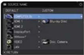 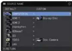 (3) Select an icon you want to assign to the port in the SOURCE NAME dialog.The name assigned to the port is automatically switched according to your icon selection. Press the ENTER or INPUT button to determine your icon selection.(4) Select a number you want to assign to the port along with the icon. You can select the number either from blank (no number assigned), 1, 2, 3, or 4.Then press the ENTER or INPUT button.(5) If you want to modify the name assigned to the port, select CUSTOM NAME and press the ENTER or INPUT button.LWU720i/LHD720iLWU620i (3) Select an icon you want to assign to the port in the SOURCE NAME dialog.The name assigned to the port is automatically switched according to your icon selection. Press the ENTER or INPUT button to determine your icon selection.(4) Select a number you want to assign to the port along with the icon. You can select the number either from blank (no number assigned), 1, 2, 3, or 4.Then press the ENTER or INPUT button.(5) If you want to modify the name assigned to the port, select CUSTOM NAME and press the ENTER or INPUT button.LWU720i/LHD720iLWU620i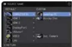 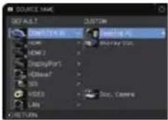 |
(continued on next page)
| Item Description | |
| SOURCE NAME(continued) | (6) The current name is displayed on the first line. Use the ▲/▼/◄/► buttons and the ENTER or INPUT button to select and enter characters. To erase one character at a time, press the RESET button or press the ◀ and INPUT button simultaneously. Also if you move the cursor to DELETE or CLEAR ALL on screen and press the ENTER or INPUT button, one or all characters are erased. The name can be a maximum of 16 characters.(7) To change an already inserted character, press the ▲ button to move the cursor to the first line, and use the ◀/► buttons to move the cursor on the character to be changed.After pressing the ENTER or INPUT button, the character is selected. Then, follow the same procedure as described at the item (6) above.(8) To finish entering text, move the cursor to the OK on screen and press the ►, ENTER or INPUT button. To revert to the previous name without saving changes, move the cursor to the CANCEL on screen and press the ◀, ENTER or INPUT button. |
| TEMPLATE | Using the ▲/▼ cursor buttons switches the mode for the template screen.Press the ► cursor (or the ENTER) button to display the selected template, and press the ◀ cursor button to close the displayed screen.The last selected template is displayed when the MY BUTTON allocated to the TEMPLATE function is pressed (89).TEST PATTERN ⇔ DOT-LINE1 ⇔ DOT-LINE2 ⇔ DOT-LINE3 ↑↓ STACK ⇔ MAP2 ⇔ MAP1 ⇔ CIRCLE2 ⇔ CIRCLE1 ⇔ DOT-LINE4 You can turn a map upside down and scroll it horizontally when MAP1 or MAP2 is selected. To invert or scroll the map, display the guidance by pressing the RESET button on the remote three seconds or more when MAP1 or MAP2 appears. |
(continued on next page)
| Item Description | |
| Closed Caption C.C. | The Closed Caption C.C. is the function that displays a transcript or dialog of the audio portion of a video, files or other presentation or other relevant sounds. It must have NTSC format video or 480i@60 format component video source supporting Closed Caption C.C. feature to utilize this function.It may not work properly, depending on equipment or signal source.In this case, turn off the Closed Caption. |
| DISPLAYSelect Closed Caption DISPLAY setting from following options using ▲/▼ buttons.AUTO ⇔ ON ⇔ OFFAUTO: Closed Caption automatically appears when the input signal (Closed Caption C.C. compatible) from the port with the mute icon set at AUDIO SOURCE is selected.ON: Closed Caption is on.OFF: Closed Caption is off.The caption is not displayed when the OSD menu is active.The Closed Caption is the function to display the dialogue, narration, and / or sound effects of a television program or other video sources. The Closed Caption availability depends upon broadcaster and/or content. | |
| MODESelect Closed Caption MODE setting from following options using ▲/▼ buttons.CAPTIONS ⇔ TEXTCAPTIONS: Display Closed Caption.TEXT: Display Text data, which is for additional information such as news reports or a TV program guide. The information covers the entire screen. Not all of the Closed Caption C.C. program has Text information. | |
| CHANNELSelect Closed Caption CHANNEL from following options using ▲/▼ buttons.1 ⇔ 2 ⇔ 3 ⇔ 41: Channel 1, primary channel / language2: Channel 23: Channel 34: Channel 4The channel data may vary, depending on the content. Some channel might be used for secondary language or empty. | |
OPTION menu
Select an item from the Option menu using the ▲/▼ cursor buttons, and press the ▶ cursor button or ENTER button to execute the item. Then perform it according to the following table.
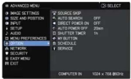
text_image
ADVANCED MENU IMAGE SETTINGS SIZE AND POSITION INPUT SETUP AUDIO MENU PREFERENCES OPTION NETWORK SECURITY EASY MENU EXIT SOURCE SKIP AUTO SEARCH OFF DIRECT POWER ON OFF AUTO POWER OFF 20in SHUTTER TIMER In MY BUTTON SCHEDULE SERVICE COMPUTER IN 1024 x 768 MHz| Item Description | |
| SOURCE SKIP | The ports can be set to be ignored in searching by the AUTO SEARCH function (below) or in selecting by buttons on the control panel.LWU720i/LHD720iLWU620i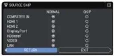 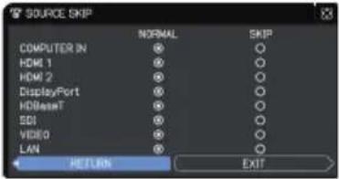 (1) Choose a picture input port using the ▲/▼ buttons.(2) Using the ◀/►buttons turns on/off the SOURCE SKIP function.NORMAL ⇔ SKIPThe port that is set to SKIP is ignored.You cannot set SKIP to all ports at the same time.This setting is not valid when in the PbyP / PIP mode (53). (1) Choose a picture input port using the ▲/▼ buttons.(2) Using the ◀/►buttons turns on/off the SOURCE SKIP function.NORMAL ⇔ SKIPThe port that is set to SKIP is ignored.You cannot set SKIP to all ports at the same time.This setting is not valid when in the PbyP / PIP mode (53). |
| AUTO SEARCH | Using the ▲/▼ buttons turns on/off the automatic signal search function.ON ⇔ OFFWhen ON is selected, detecting no signal automatically cycles through input ports in the following order. The search is started from the current port. When an input is found, the projector stops searching and display the image.LAN ⇒ COMPUTER IN ⇒ HDMI 1↑ ↓VIDEO HDMI 2↑ ↓SDI* ⇌ HDBaseT ⇌ DisplayPort |
* LWU720i/LHD720i only
(continued on next page)
| Item Description | Option |
| DIRECT POWER ON | Using the ▲/▼ buttons turns on/off the DIRECT POWER ON function.ON ⇔ OFFWhen set to ON, the lamp in projector is automatically turned on without the usual procedure (35), only when the projector is supplied with the power after the power was cut while the lamp was on.This function does not work as long as the power has been supplied to the projector while the lamp is off.After turning the lamp on by the DIRECT POWER ON function, if neither input nor operation is detected for about 30 minutes, the projector is turned off, even though the AUTO POWER OFF function (below) is disabled. |
| AUTO POWER OFF | Using the ▲/▼ buttons adjusts the time to count down to automatically turn the projector off.Long (max. 99 minutes) ⇔ Short (min. 0 minute = DISABLE)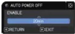  When the time is set to 0, the projector is not turned off automatically.When the time is set to 1 to 99, and when the passed time with no-signal or an unsuitable signal reaches at the set time, the projector lamp is turned off.If one of the projector's buttons or the remote control buttons is pressed or one of the commands (except get commands) is transmitted to the CONTROL port during the corresponding time, the projector is not turned off.Refer to the section Turning off the power (35). When the time is set to 0, the projector is not turned off automatically.When the time is set to 1 to 99, and when the passed time with no-signal or an unsuitable signal reaches at the set time, the projector lamp is turned off.If one of the projector's buttons or the remote control buttons is pressed or one of the commands (except get commands) is transmitted to the CONTROL port during the corresponding time, the projector is not turned off.Refer to the section Turning off the power (35). |
| SHUTTER TIMER | Using the ▲/▼ buttons sets the time from closing the shutter to automatically turning the projector off.1h ⇔ 3h ⇔ 6hThe shutter opens automatically when turning the projector on again. |
(continued on next page)
| Item Description | This item is to assign one of the following functions toMY BUTTON(1 to 4) on the remote control (7).(1) Use the ▲/▼ buttons on the MY BUTTON menu to select a button from MY BUTTON - 1 to 4 and press the ▶ or ENTERbutton to display the MY BUTTON setup dialog.(2) Then using the ▲/▼/◄/► buttons sets one of the following functions to the chosen button. Press theENTERor INPUTbutton to save the setting.MY IMAGE: Displays the MY IMAGE menu.(5. My Image Function in the Network Guide)MESSENGER: Turns the messenger text displayed on the screen on/off (6. Messenger Function in the Network Guide).When there is no transferred text data to display, the message "NO MESSENGER DATA" appears.BLANK: Switches the BLANK function to on or off.SHUTTER: Turns the shutter closed and opened (52).PbyP / PIP SWAP: Swaps the picture on the right with one on the left in the PbyP mode. Swaps the primary picture and the secondary picture in the PIP mode. (53)PIP POSITION: Toggles the PIP position.INFORMATION: Displays SYSTEM INFORMATION,INPUT INFORMATION (100), WIRELESS INFORMATION,WIRED INFORMATION or nothing.MY MEMORY: Loads one of adjustment data stored (65).When more than one data are saved, the adjustment changes every time theMY BUTTONis pressed.When no data is saved in memory, thedialog "No saved data" appears.When the current adjustment is notsaved to memory, the dialog as shown inthe right appears.To keep the current adjustment, press the ► button to exit. Otherwise loading a data overwrites the current adjusted condition.DYNAMIC IRIS: Changes the dynamic iris mode (62).PICTURE MODE: Changes the PICTURE MODE (63).FILTER RESET: Displays the filter hours reset confirmation dialogue (76).TEMPLATE: Makes the template pattern selected to the TEMPLATE item (85) appear or disappear.MUTE: Turns the audio mute on/off.RESOLUTION: Turns on/off the RESOLUTION dialog (72).ECO MODE: Changes the ECO MODE dialog (75). |
| MY BUTTON |
(continued on next page)
| Item Description | |
| MY BUTTON(continued) | eClarity:Turns on/off the eClarity dialog (65).HDCR:Turns on/off the HDCR dialog (65).STATUS MONITOR:Turns on/off the back light of status monitor(31). This function is unavailable when POWER SAVE is selected in STANDBY MODE while the projector is in the standby mode. |
| SCHEDULE | ■ How to setup the item1. Use the ▲/▼/◄/► cursor buttons to select or adjust.2. Select OK to finish the settings.NOTE·Refer to the actual on-screen display(OSD) for appropriate operation. |
| Item Description | |
| DATE & TIME | |
| SPECIFIC DATE | |
| PROGRAM EDIT | |
| ■ Setting procedure1 Determine the current date/time as reference in DATE AND TIME.2 Make a schedule of what event to execute at what time of the day in PROGRAM EDIT.3 Select the date (one specific day: SPECIFIC DATE or the days of the week: every week) to be scheduled, then select a program.Switch the screen of the days of the week and SPECIFIC DATE by vertical scroll.(Page 1 of 2: Days of the week, Page 2 of 2: SPECIFIC DATE) | |
(continued on next page)
Item Description
SCHEDULE (continued)
■ How to activate (DATE AND TIME / SPECIFIC DATE)
Place a checkmark in the box.
Checkmark in the box
Date and first setup info could be seen with the check mark.
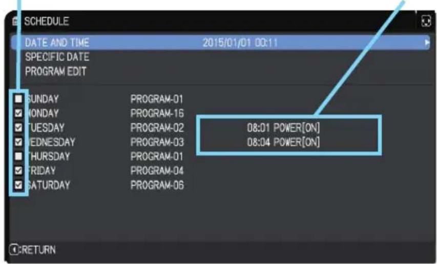
text_image
SCHEDULE DATE AND TIME 2015/01/01 00:11 SPECIFIC DATE PROGRAM EDIT SUNDAY PROGRAM-01 MONDAY PROGRAM-16 TUESDAY PROGRAM-02 08:01 POWER[ON] EDNESDAY PROGRAM-03 08:04 POWER[ON] THURSDAY PROGRAM-01 FRIDAY PROGRAM-04 SATURDAY PROGRAM-06 RETURN1/2 page (Set the DATE(Year/Month/Date) and Time(24-hour scale).)
Checkmark in the box
Date and first setup info could be seen with the check mark.
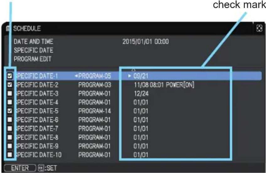
text_image
SCHEDULE DATE AND TIME 2015/01/01 00:00 SPECIFIC DATE PROGRAM EDIT ✓ SPECIFIC DATE-1 ✓ SPECIFIC DATE-2 ✓ SPECIFIC DATE-3 ✓ SPECIFIC DATE-4 ✓ SPECIFIC DATE-5 ✓ SPECIFIC DATE-6 ✓ SPECIFIC DATE-7 ✓ SPECIFIC DATE-8 ✓ SPECIFIC DATE-9 ✓ SPECIFIC DATE-10 ✓ PROGRAM-05 PROGRAM-03 PROGRAM-01 PROGRAM-01 PROGRAM-14 PROGRAM-01 PROGRAM-01 PROGRAM-01 PROGRAM-01 PROGRAM-01 PROGRAM-01 PROGRAM-01 program-01 program-01 program-01 program-01 program-01 program-01 program-01 program-01 program-01 program-01 program-01 program-01 program-01 program-01 program-01 program-01 program-01 program-01 program-01 program-01 enter :SET2/2 page (Set specific date from 1 to 10.)
Press the ▼ cursor button to move from 1/2 page to 2/2 page with the state of selecting "SATURDAY".
(continued on next page)
| Item Description | ||
| SCHEDULE (continued) | ■ PROGRAM EDITThe TIME and EVENT for Program 1 to 16 can be edited.RETURNSelect this to return to the top menu of the SCHEDULE.SELECT Select from PROGRAM-01 to 16 to edit.Up to 20 events can be set in each program.COPY TOThe selected program (with the settings of TIME and EVENT) can be copied to other program.APPLYSelect this to apply and save all adjustments and settings. | 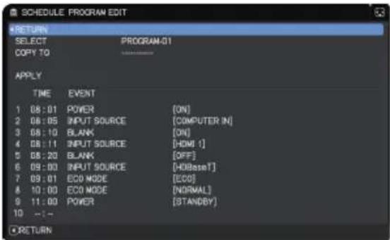 |
(continued on next page)
Item Description
SCHEDULE (continued)
■ How to edit the selected PROGRAM
- Select from 1 to 20 events.
Use the ▲/▼ cursor buttons to select.
Press ▶ cursor button to set the TIME and EVENT.
-
Use the ◀/▶ cursor buttons to select.
-
Use the ▲/▼ cursor buttons to adjust.
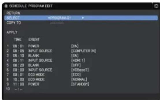
text_image
SCHEDULE PROGRAM EXIT RETURN SELECT *PROGRAM-01 COPY TO APPLY TIME EVENT 1 08:01 POWER [ON] 2 08:05 Nepal INPUT SOURCE [COMPUTER IN] 3 08:10 BLANK [ON] 4 08:11 INPUT SOURCE[HDMI 1] 5 08:20 BLANK [OFF] 6 09:00 INPUT SOURCE[HDBaseT] 7 09:01 ECO MODE [ECO] 8 10:00 ECO MODE[NORMAL] 9 11:00 POWER [STANDSY] 10 --:-EVENT can be selected as listed below.
• POWER - ON, STANDBY
• INPUT SOURCE - "input source"channel
• MY IMAGE - IMAGE-1 to 4, IMAGE OFF
• MESSENGER - TEXT-1 to 12, TEXT OFF
- ECO MODE - NORMAL, ECO
- BLANK - ON, OFF
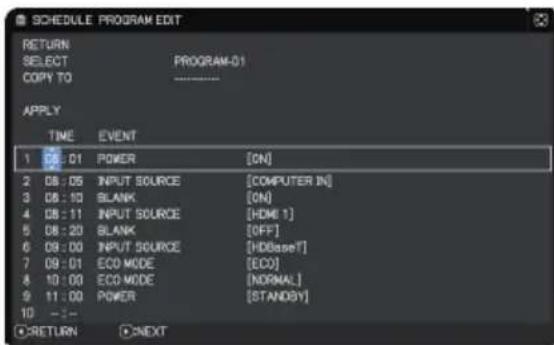
text_image
SCHEDULE PROGRAM EDIT RETURN SELECT PROGRAM-01 COPY TO ------------------ APPLY TIME EVENT 1 01 POWER [ON] 2 08:05 INPUT SOURCE [COMPUTER IN] 3 08:10 SLANK [ON] 4 08:11 INPUT SOURCE [HDMI 1] 5 08:20 BLANK [OFF] 6 09:00 INPUT SOURCE [HDBaseY] 7 09:01 ECO MODE [ECO] 8 10:00 ECO MODE [NORMAL] 9 11:00 POWER [STANDSY] 10 - : - RETURN ONEXT- Press ▶ cursor button to finish the settings.
- Select APPLY to save the settings.
NOTE • Refer to the on-screen display(OSD) for the appropriate operation.
- When the STANDBY MODE is set to POWER SAVE, SCHEDULE function (Ex:POWER-ON) at STANBY MODE will not be operated.
(continued on next page)
| Item Description | |
| SERVICE | Selecting this item displays the SERVICE menu.Select an item using the ▲/▼ buttons, and press the ▶ button or the ENTER button on the remote control to execute the item. 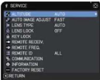 |
| ALTITUDEUsing the ▲/▼ buttons switches the rotation speed of the cooling fans. It is recommended to leave it at AUTO.HIGH-2 ⇔ HIGH-1 ⇔ NORMAL ⇔ AUTOAUTO: The projector changes the rotation speed automatically to suit the altitude and other environmental factors.Choose an option below when there is a trouble with the AUTO mode.NORMAL: This mode can be used below 1600m (5250ft.).HIGH-1: This mode can be used between 1600 to 2300m (5250 to 7550ft.).HIGH-2: This mode can be used above 2300m (7550ft.). | |
| AUTO IMAGE ADJUSTUsing the ▲/▼ buttons to select one of the mode. When the DISABLE is selected, the automatic adjustment feature is disabled.FINE ⇔ FAST ⇔ DISABLEFINE: Finer tuning including H.SIZE adjustment.FAST: Faster tuning, setting H.SIZE to prearranged data for the input signal.• Depending on conditions, such as input image, signal cable to the projector, environment around the projector, and so on, the automatic adjustment may not work correctly. If this occurs, choose DISABLE to disable the automatic adjustment, and make the adjustment manually. | |
(continued on next page)
| Item Description | |
| SERVICE(continued) | LENS TYPE(1) Select the lens type currently used using the ▲/▼ buttons and press the ▶ or ENTER button. If AUTO is selected, the projector determines the lens type automatically.(2) A message dialog is displayed for confirmation. Press the ▶ or ENTER button to save the lens type.This setting has an influence on the keystone distortion and so on.The lens type determined by the projector is displayed on the right of "AUTO".If the projector cannot determine the lens type automatically when this item is set to AUTO, "UNKNOWN LENS" is displayed on the right of "AUTO".For information about the optional lens, contact your dealer. |
| LENS LOCKUsing the ▲/▼ buttons turns on/off the lens lock feature. When ON is selected, the buttons (ZOOM, ZOOM + / -, FOCUS + / -, LENS SHIFT, LENS MEMORY) are locked.ON ⇔ OFF | |
(continued on next page)
| Item Description | |
| SERVICE (continued) | KEY LOCK(1) Use the ▲/▼ buttons to choose the operations control.CONTROL PANEL ⇔ REMOTE CONTROL(2) Use the ◀/► buttons to select ON or OFF.ON ⇔ OFFSelecting ON in Step 2 locks the buttons except STANDBY, ON and STANDBY/ON on the operations control selected in Step 1.Selecting OFF releases the locked buttons on the operations control selected in Step 1.• Use this function to prevent tampering or accidental operation.• You cannot disable both options at the same time. |
| REMOTE RECEIV.(1) Select a remote sensor using the ▲/▼ button.FRONT ⇔ REAR ⇔ HDBaseT(2) Switch it using the ◀/► button.ON ⇔ OFF• When one sensor is turned off, the other cannot be turned off. | |
| REMOTE FREQ.(1) Use the ▲/▼ button to change the projector's remote sensor frequency setting (4, 29).1:NORMAL ⇔ 2:HIGH(2) Use the ◀/► button to change the projector's remote sensor on or off.ON ⇔ OFFIf the remote control does not function correctly, disable either of them.• You cannot disable both options at the same time. | |
| REMOTE IDUse the ▲/▼ buttons on the REMOTE ID menu to select ID and press the ► button.ALL ⇔ 1 ⇔ 2 ⇔ 3 ⇔ 4The projector is controlled by the remote control whose ID button is set the same number as this number. When the ALL is selected, the projector is controlled by a remote control irrespective of the ID setting. | |
(continued on next page)
| Item Description | ||
| SERVICE(continued) | COMMUNICATION | Selecting this item displays COMMUNICATION menu.In this menu, you can configure the serial communication settings of the projector using theCONTROL port.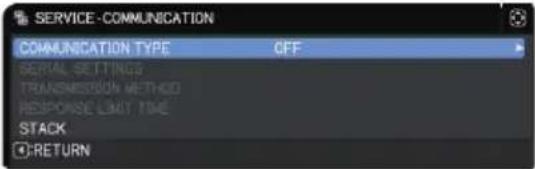 Select an item using the cursor buttons ▲/▼. Then pressing the ► button opens the submenu for the setting item you selected. Or, pressing the ◀ button instead of the ► button makes the menu back to the previous one without changing the setup. Each submenu can be operated as described above.When COMMUNICATION TYPE (below) is set to OFF, the other items except STACK in COMMUNICATION menu are invalid.For the function of serial communication, refer to theNetwork Guide. Select an item using the cursor buttons ▲/▼. Then pressing the ► button opens the submenu for the setting item you selected. Or, pressing the ◀ button instead of the ► button makes the menu back to the previous one without changing the setup. Each submenu can be operated as described above.When COMMUNICATION TYPE (below) is set to OFF, the other items except STACK in COMMUNICATION menu are invalid.For the function of serial communication, refer to theNetwork Guide. |
| COMMUNICATION TYPESelect the communication type for transmission using theCONTROL port.NETWORK BRIDGE (WIRELESS)NETWORK BRIDGE (WIRED)OFFNETWORK BRIDGE: Select this type, if it is required to control an external device as a network terminal, using this projector from the computer. Select WIRELESS or WIRED as your network connection mode.TheCONTROL port does not accept RS-232C commands (7. Network Bridge Function in the Network Guide).OFF: Select this mode to receive RS-232C commands using theCONTROL port.OFF is the default setting.When you select the NETWORK BRIDGE, check the item, TRANSMISSION METHOD (98). | ||
(continued on next page)
| Item Description | ||
| SERVICE(continued) | COMMUNICATION(continued) | SERIAL SETTINGSSelect the serial communication condition for theCONTROL port.BAUD RATE4800bps ⇔ 9600bps ⇔ 19200bps ⇔ 38400bps↑↓↓↓↓↓↓↓↓↓↓↓↓↓↓↓↓↓↓↓↓↓↓↓↓↓↓↓↓↓↓↓↓↓↓↓↓↓↓↓↓↓↓↓↓↓↓↓↓↓↓↓↓↓↓↓↓↓↓↓↓↓↓↓↓↓↓↓↓↓↓↓↓↓↓↓↓↓↓↓↓↓↓↓↓↓↓↓↓↓↓↓↓↓↓↓↓↓↓↓↓ ↓The BAUD RATE is fixed to 19200bps and PARITYis fixed NONE when the COMMUNICATION TYPEis set to OFF (97). |
| TRANSMISSION METHODSelect the transmission method for communication bythe NETWORK BRIDGE from theCONTROL port.HALF-DUPLEX ⇔ FULL-DUPLEXHALF-DUPLEX: This method lets the projectormake two way communication, but only onedirection, either transmitting or receiving data, isallowed at a time.FULL-DUPLEX: This method lets the projectormake two way communication, transmitting andreceiving data at the same time.·HALF-DUPLEX is selected as the default setting.·If you select HALF-DUPLEX, check the setting ofthe item RESPONSE LIMIT TIME (99). | ||
(continued on next page)
| Item Description | ||
| SERVICE(continued) | COMMUNICATION(continued) | RESPONSE LIMIT TIMESelect the time period to wait for receiving response data from other device communicating by the NETWORK BRIDGE and the HALF-DUPLEX through theCONTROLport.OFF ⇔ 1s ⇔ 2s ⇔ 3sOFF: Select this mode if it is not required to check the responses from the device that the projector sends data to. In this mode, the projector can send out data from the computer continuously.1s /2s /3s: Select the time period to keep the projector waiting for response from the device that the projector sends data to. While waiting a response, the projector does not send out any data from theCONTROLport.This menu is available only when the NETWORK BRIDGE is selected for the COMMUNICATION TYPE and the HALF-DUPLEX is selected for the TRANSMISSION METHOD (98).OFF is selected as the default setting. |
| STACKSelecting this item displays the STACK menu. For more information, see theInstant Stack Guide.When STACK MODE is set to MAIN or SUB, the other items in COMMUNICATION menu are invalid. | ||
(continued on next page)
| Item Description | |||
| SERVICE (continued) | INFORMATIONSelecting this item displays a dialog titled “INPUT INFORMATION”. It shows the information about the current input. | ||
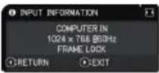 | 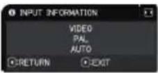 | 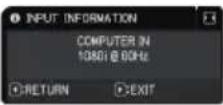 | |
| • The “FRAME LOCK” message on the dialog means the frame lock function is working.• This item cannot be selected for no signal and sync out.• When the MY TEXT DISPLAY is set to ON, the MY TEXT is displayed together with the input information in the INPUT INFORMATION box (107). | |||
| FACTORY RESETSelecting OK using the ▶ button performs this function. By this function, all menu items are collectively returned to the initial setting. Note that the items LAMP HOURS, FILTER HOURS, LANGUAGE, AUTO BLANK, FILTER MESSAGE, STANDBY MODE, COMMUNICATION, NETWORK and SECURITY settings are not reset.CANCEL ⇒ OK | |||
NETWORK menu
See the Network Guide for details of NETWORK operation.
Remember that incorrect network settings on this projector may cause trouble on the network. Consult with your network administrator before connecting to an existing access point on your network.
SECURITY menu
This projector is equipped with security functions. From the SECURITY menu, items shown in the table below can be performed.
To use SECURITY menu: User registration is required before using the security functions.
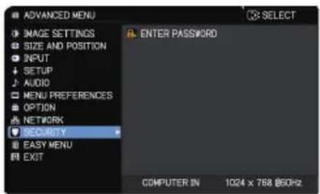
text_image
ADVANCED MENU IMAGE SETTINGS SIZE AND POSITION INPUT SETUP AUDIO MENU PREFERENCES OPTION NETWORK SECURITY EASY MENU EXIT ENTER PASSWORD COMPUTER IN 1024 x 768 @50HzEnter to the SECURITY menu
- Press the ▶ button. The ENTER PASSWORD box is displayed.
- Use the ▲/▼/◄/► buttons to enter the registered password. The factory default password is as follows.
LWU720i/LWU620i : 6614 LHD720i : 5014
This password can be changed (below). Move the cursor to the right side of the ENTER PASSWORD box and press the ▶ button to display the SECURITY menu.
- It is strongly recommended the factory default password to be changed as soon as possible.
-
If an incorrect password is input, the ENTER PASSWORD box is displayed again. If incorrect password is input three times, the projector turns off. Afterwards the projector then turns off every time an incorrect password is input.
-
Items shown in the table below can be performed.

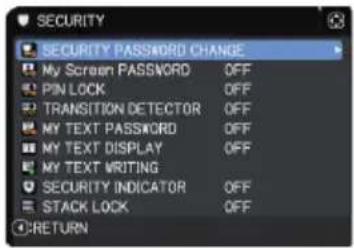
text_image
SECURITY SECURITY PASSWORD CHANGE My Screen PASSWORD OFF PIN LOCK OFF TRANSITION DETECTOR OFF MY TEXT PASSWORD OFF MY TEXT DISPLAY OFF MY TEXT WRITING SECURITY INDICATOR OFF STACK LOCK OFF RETURNIf you have forgotten your password
(1) While the ENTER PASSWORD box is displayed, press and hold the RESET button on the remote control for approximately three seconds or press and hold the INPUT button for three seconds while pressing the ▶ button on the projector.
(2) The 10 digit Inquiring Code is displayed. Contact your dealer with the 10 digit Inquiring Code. Your password is sent after your user registration information is confirmed.
- If there is no key input for approximately 55 seconds while the Inquiring Code is displayed, the menu closes. If necessary, repeat the process from (1).

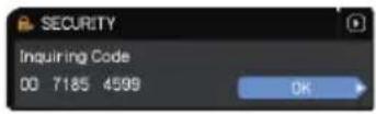
| Item Description | |
| SECURITY PASSWORD CHANGE | (1) Use the ▲/▼ buttons on the SECURITY menu to select SECURITY PASSWORD CHANGE and press the ▶ button to display the ENTER NEW PASSWORD box.  (2) Use the ▲/▼/◄/► buttons to enter the new password.(3) Move the cursor to the right side of the ENTER NEW PASSWORD box and press the ► button to display the NEW PASSWORD AGAIN box, enter the same password again. (2) Use the ▲/▼/◄/► buttons to enter the new password.(3) Move the cursor to the right side of the ENTER NEW PASSWORD box and press the ► button to display the NEW PASSWORD AGAIN box, enter the same password again.  (4) Move the cursor to the right side of the NEW PASSWORD AGAIN box and press the ► button and the NOTE NEW PASSWORD box is displayed for approximately 30 seconds. Make note of the password during this time. Pressing the ENTER button on the remote control or ► button on the projector closes the NOTE NEW PASSWORD box.· Do not forget your password. (4) Move the cursor to the right side of the NEW PASSWORD AGAIN box and press the ► button and the NOTE NEW PASSWORD box is displayed for approximately 30 seconds. Make note of the password during this time. Pressing the ENTER button on the remote control or ► button on the projector closes the NOTE NEW PASSWORD box.· Do not forget your password.  |
(continued on next page)
Item Description
My Screen PASSWORD
The My Screen PASSWORD function can be used to prohibit access to the My Screen function and prevent the currently registered My Screen image from being overwritten.
1 Turning on the My Screen PASSWORD
1-1 Use the ▲/▼ buttons on the SECURITY menu to select My Screen PASSWORD and press the ▶ button to display the My Screen PASSWORD on/off menu.
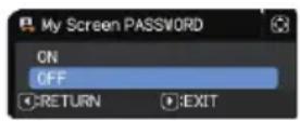
1-2 Use the ▲/▼ buttons on the My Screen PASSWORD on/off menu to select ON. The ENTER NEW PASSWORD box (small) is displayed.
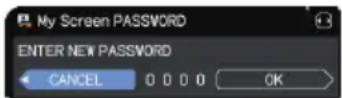
1-3 Use the ▲/▼/◄/► buttons to enter the password. Move the cursor to the right side of the ENTER NEW PASSWORD box (small) and press the ► button to display the NEW PASSWORD AGAIN box, enter the same PASSWORD again.
ENTER NEW PASSWORD box (small)

1-4 Move the cursor to the right side of the NEW PASSWORD AGAIN box and press the ▶ button to display the NOTE NEW PASSWORD box for approximately 30 seconds. Make note of the password during this time.
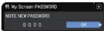
Pressing the ENTER button on the remote control or ▶ button on the projector returns to My Screen PASSWORD on/off menu.
When a password is set for My Screen:
- The My Screen registration function (and menu) are unavailable.
• The My Screen Lock menu is unavailable.
- The START UP setting is locked on My Screen (and the menu is unavailable).
Turning the My Screen PASSWORD off allows normal operation of these functions.
- Do not forget your My Screen PASSWORD.
2 Turning off the My Screen PASSWORD
2-1 Follow the procedure in 1-1 to display the My Screen PASSWORD on/off menu.
2-2 Select OFF to display the ENTER PASSWORD box (large). Enter the registered password and the screen returns to the My Screen PASSWORD on/off menu.
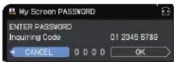
text_image
My Screen PASSWORD ENTER PASSWORD Inquiring Code 01 2345 6789 CANCEL 0 0 0 0 OKENTER PASSWORD box (large)
If an incorrect PASSWORD is entered, the menu closes. If necessary, repeat the process from 2-1.
3 If you have forgotten your password
3-1 Follow the procedure in 1-1 to display the My Screen PASSWORD on/off menu.
3-2 Select OFF to display the ENTER PASSWORD box (large). The 10 digit Inquiring Code is displayed inside the box.
3-3 Contact your dealer with the 10 digit Inquiring Code. Your password is sent after your user registration information is confirmed.
(continued on next page)
| Item Description | |
| PIN LOCK | PIN LOCK is a function which prevents the projector from being used unless a registered Code is input.1 Turning on the PIN LOCK1-1 Use the ▲/▼ buttons on the SECURITY menu to select PIN LOCK and press the ▶ button or the ENTER button to display the PIN LOCK on/off menu.1-2 Use the ▲/▼ buttons on the PIN LOCK on/off menu to select ON and the Enter PIN Code box is displayed.1-3 Input a four part PIN code using the ▲/▼/◄/►, COMPUTER 1 or INPUT button.The PIN Code again box appears. Reenter the same PIN code. This completes the PIN code registration.If there is no key input for approximately 55 seconds while the Enter PIN Code box or the PIN Code again box is displayed, the menu closes. If necessary, repeat the process from 1-1.Anytime the projector is restarted after AC power is turned off, the Enter PIN Code box is displayed. Enter the registered PIN code.The projector can be used after entering the registered PIN code. If an incorrect PIN code is input, the Enter PIN code box is displayed again.If an incorrect PIN code is input three times, the projector turns off.Afterwards the projector turns off every time an incorrect PIN code is input.The projector also turns off if there is no key input for approximately five minutes while the Enter PIN code box is displayed.This function activates only when the projector is started after AC power is turned off.Do not forget your PIN code.Turning off the PIN LOCK2-1 Follow the procedure in 1-1 to display the PIN LOCK on/off menu.2-2 Use the ▲/▼ buttons to select OFF and the Enter PIN Code box is displayed.Enter the registered PIN code to turn the PIN LOCK function off.If an incorrect PIN code is input three times, the projector turns off.If you have forgotten your PIN code3-1 While the Enter PIN code box is displayed, press and hold the RESET button for three seconds or press and hold the INPUT button for three seconds while pressing the ▶ button on the projector.The 10 digit Inquiring Code is displayed.If there is no key input for approximately five minutes while the Inquiring Code is displayed, the projector turns off.Contact your dealer with the 10 digit Inquiring Code. Your PIN code is sent after your user registration information is confirmed. |
(continued on next page)
Item Description
TRANSITION DETECTOR
If this function is set to ON and the vertical angle of the projector or the INSTALLATION setting is different from the previous recorded setting, the TRANSITION DETECTOR ON alarm is displayed and the input signal is not displayed.
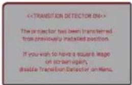
text_image
<• To display the signal again, set this function OFF.
• After approximately five minutes of displaying the TRANSITION DETECTOR ON alarm, the lamp turns off.
1 Turning on the TRANSITION DETECTOR
1-1 Use the ▲/▼ buttons on the SECURITY menu to select TRANSITION DETECTOR and press the ▶ or the ENTER button to display the TRANSITION DETECTOR on/off menu.
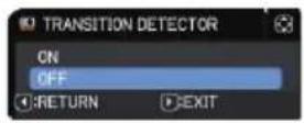
1-2 Use the ▲/▼ buttons on the TRANSITION DETECTOR on/off menu to select ON. Selecting ON saves the setting of the current angle and the INSTALLATION setting. The ENTER NEW PASSWORD box (small) is displayed.

text_image
TRANSITION DETECTOR ENTER NEW PASSWORD CANCEL 0 0 0 0 OK ENTER NEW PASSWORD box (small)1-3 Use the ▲/▼/◄/► buttons to enter a password. Move the cursor to the right side of the ENTER NEW PASSWORD box (small) and press the ► button to display the NEW PASSWORD AGAIN box, enter the same password again.

1-4 Move the cursor to the right side of the NEW PASSWORD AGAIN box and press the ▶ button to display the NOTE NEW PASSWORD box for about 30 second. Make note of the password.

Pressing the ENTER button on the remote control or the ▶ button on the projector returns to the TRANSITION DETECTOR on/off menu.
- Do not forget your TRANSITION DETECTOR password.
- This function activates only when the projector is started after turning off the AC power.
- This feature may not function properly if the projector is not in a stable position when ON is selected.
2 Turning off the TRANSITION DETECTOR
2-1 Follow the procedure in 1-1 to display the TRANSITION DETECTOR on/off menu.
2-2 Select OFF to display the ENTER
PASSWORD box (large). Enter the registered password and the screen returns to the TRANSITION DETECTOR on/off menu.

text_image
TRANSITION DETECTOR ENTER PASSWORD Inquiring Code 10 2819 0605 CANCEL OKIf an incorrect password is entered, the menu closes. If necessary, repeat the process from 2-1.
ENTER PASSWORD box (large)
3 If you have forgotten your password
3-1 Follow the procedure in 1-1 to display the TRANSITION DETECTOR on/off menu.
3-2 Select OFF to display the ENTER PASSWORD box (large). The 10 digit Inquiring Code is displayed inside the box.
3-3 Contact your dealer with the 10 digit Inquiring Code. Your password is sent after your user registration information is confirmed.
(continued on next page)
| Item Description | |
| MY TEXT PASSWORD | The MY TEXT PASSWORD function can prevent the MY TEXT from being overwritten. When the password is set for the MY TEXT;• The MY TEXT DISPLAY menu is unavailable, which can prohibit changing the DISPLAY setting.• The MY TEXT WRITING menu is unavailable, which can prevent the MY TEXT from being overwritten.1 Turning on the MY TEXT PASSWORD1-1 Use the ▲/▼ buttons on the SECURITY menu to select the MY TEXT PASSWORD and press the ▶ button to display the MY TEXT PASSWORD on/off menu.  1-2 Use the ▲/▼ buttons on the MY TEXT PASSWORD on/off menu to select ON. The ENTER NEW PASSWORD box (small) is displayed. 1-2 Use the ▲/▼ buttons on the MY TEXT PASSWORD on/off menu to select ON. The ENTER NEW PASSWORD box (small) is displayed.  1-3 Use the ▲/▼/◄/► buttons to enter the password. Move the cursor to the right side of the ENTER NEW PASSWORD box (small) and press the ► button to display the NEW PASSWORD AGAIN box, and then enter the same password again. 1-3 Use the ▲/▼/◄/► buttons to enter the password. Move the cursor to the right side of the ENTER NEW PASSWORD box (small) and press the ► button to display the NEW PASSWORD AGAIN box, and then enter the same password again.  1-4 Move the cursor to the right side of the NEW PASSWORD AGAIN box and press ► button to display the NOTE NEW PASSWORD box for about 30 seconds. Make note of the password. 1-4 Move the cursor to the right side of the NEW PASSWORD AGAIN box and press ► button to display the NOTE NEW PASSWORD box for about 30 seconds. Make note of the password.  Pressing the ENTER button on the remote control or ► button on the projector returns to the MY TEXT PASSWORD on/off menu.2 Turning off the MY TEXT PASSWORD2-1 Follow the procedure in 1-1 to display the MY TEXT PASSWORD on/off menu.2-2 Select OFF to display the ENTER PASSWORD box (large). Enter the registered password and the screen returns to the MY TEXT PASSWORD on/off menu. Pressing the ENTER button on the remote control or ► button on the projector returns to the MY TEXT PASSWORD on/off menu.2 Turning off the MY TEXT PASSWORD2-1 Follow the procedure in 1-1 to display the MY TEXT PASSWORD on/off menu.2-2 Select OFF to display the ENTER PASSWORD box (large). Enter the registered password and the screen returns to the MY TEXT PASSWORD on/off menu.  If an incorrect password is input, the menu closes. If necessary, repeat the process from 2-1 ENTER PASSWORD box (large)3 If you have forgotten your password3-1 Follow the procedure in 1-1 to display the MY TEXT PASSWORD on/off menu.3-2 Select OFF to display the ENTER PASSWORD box (large). The 10 digit inquiring code is displayed inside the box.3-3 Contact your dealer with the 10 digit inquiring code. Your password is sent after your user registration information is confirmed. If an incorrect password is input, the menu closes. If necessary, repeat the process from 2-1 ENTER PASSWORD box (large)3 If you have forgotten your password3-1 Follow the procedure in 1-1 to display the MY TEXT PASSWORD on/off menu.3-2 Select OFF to display the ENTER PASSWORD box (large). The 10 digit inquiring code is displayed inside the box.3-3 Contact your dealer with the 10 digit inquiring code. Your password is sent after your user registration information is confirmed. |
(continued on next page)
| Item Description | ||
| MY TEXT DISPLAY | (1) Use the ▲/▼ buttons on the SECURITY menu to select the MY TEXT DISPLAY and press the ▶ or ENTER button to display the MY TEXT DISPLAY on/off menu.(2) Use the ▲/▼ buttons on the MY TEXT DISPLAY on/off menu to select on or off.ON ⇔ OFFWhen it is set ON, the MY TEXT is displayed on the START UP screen and the INPUT INFORMATION when the INFORMATION on the SERVICE menu is chosen.· This function is available only when the MY TEXT PASSWORD function is set to the OFF. | 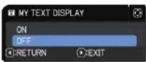  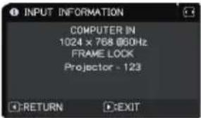 |
| MY TEXT WRITING | (1) Use the ▲/▼ buttons on the SECURITY menu to select the MY TEXT WRITING and press the ▶ button. The MY TEXT WRITING dialog is displayed.(2) The current MY TEXT is displayed on the first three lines. If not yet written, the lines is blank.Use the ▲/▼/◄/► buttons and the ENTER or INPUT button to select and enter characters. To erase 1 character at one time, press the RESET button or press the ◀ and INPUT button at the same time. If you move the cursor to DELETE or CLEAR ALL on screen and press the ENTER or INPUT button, one or all characters are erased. The MY TEXT can be input up to 24 characters on each line.(3) To change an already inserted character, press the ▲/▼ button to move the cursor to one of the first three lines, and use the ◀/► buttons to move the cursor on the character to be changed.After pressing the ENTER or INPUT button, the character is selected. Then, follow the same procedure as described at the item (2) above.(4) To finish entering text, move the cursor to the OK on screen and press the ▶, ENTER or INPUT button. To revert to the previous MY TEXT without saving changes, move the cursor to the CANCEL on screen and press the ◀, ENTER or INPUT button.· The MY TEXT WRITING function is available only when the MY TEXT PASSWORD function is set to OFF. | 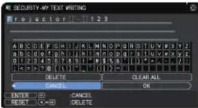 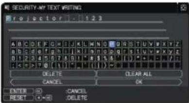 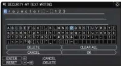 |
(continued on next page)
| Item Description | |
| SECURITY INDICATOR | Selecting this item displays the SECURITY INDICATOR dialog. Use the ▲/▼ buttons to select ON or OFF.ON ⇔ OFFWhen ON is selected while PIN LOCK or TRANSITION DETECTOR is ON, the SECURITY indicator blinks in yellow in the standby mode (104, 105). |
| STACK LOCK | Selecting this item displays the STACK LOCK dialog. For more information, see the Instant Stack Guide. |
Maintenance
Replacing the lamp
A lamp has finite product life. Using the lamp for long periods of time could cause the pictures darker or the color tone poor. Each lamp has a different lifetime, and some may burst or burn out soon after you start using them.
New lamp preparation and early replacement are recommended. To prepare a new lamp, contact your dealer and indicate the lamp type number.
Type number : 003-005336-01 (DT01885)
Replacing the lamp
- Turn the projector off, and unplug the power cord. Allow the projector to cool for at least 45 minutes.
- Prepare a new lamp. If the projector is mounted with specified mounting accessories, or if the lamp has broken, also ask the dealer to replace the lamp.
In case of replacement by yourself, follow the following procedure.
-
Loosen the screw (marked by arrow) of the lamp cover and then slide down and lift the lamp cover to remove it.
-
Loosen the three screws (marked by arrow) of the lamp, and slowly pull the lamp out by the handles. Never loosen any other screws.
-
Insert the new lamp, and firmly retighten the three screws of the lamp loosened in the previous step to lock it in place.
-
While putting the interlocking parts of the lamp cover and the projector together, slide the lamp cover back in place. Then firmly fasten the screw of the lamp cover.
-
Turn the projector on and reset the lamp time using the LAMP · HOURS item in the SETUP menu.
(1) Press the MENU button to display a menu.
(2) Point at the ADVANCED MENU in the menu using the ▼/▲ button, then press the ▶ button.
(3) Point at the SETUP in the left column of the menu using the ▼/▲button, then press the ▶ button.
(4) Point at the LAMP & FILTER using the ▼/▲button, then press the ▶ button.
(5) Point at the LAMP HOURS using the ▼/▲ button, then press the ▶ button. A dialog appears.
(6) Press the ▶ button to select "OK" on the dialog. It performs resetting the lamp time.
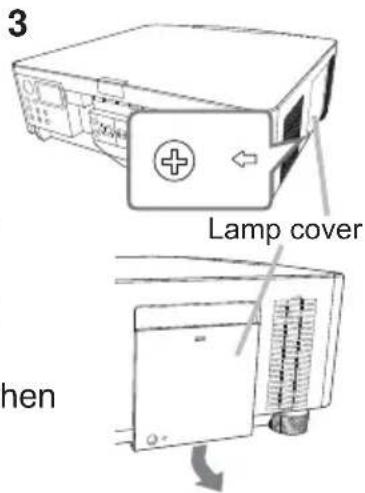
text_image
3 Lamp cover When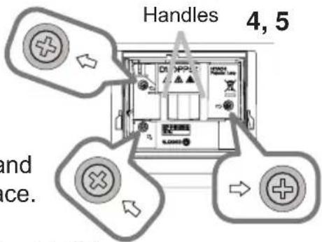
text_image
Handles 4, 5 and ice.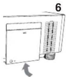
natural_image
Diagram of a front-mounted air conditioner unit with cooling fins and a heat sink, showing airflow direction (no text or symbols)⚠️ CAUTION ▶ Do not touch the interior of the projector, while the lamp is removed.
NOTE • Reset the lamp time only when you have replaced the lamp, for a suitable indication about the lamp.
Replacing the lamp (continued)
Lamp warning
HIGH VOLTAGE
HIGH TEMPERATURE
HIGH PRESSURE
WARNING ▶ The projector uses a high-pressure mercury glass lamp. The lamp can break with a loud bang, or burn out, if jolted or scratched, handled while hot, or worn over time. Note that each lamp has a different lifetime, and some may burst or burn out soon after you start using them. In addition, if the bulb bursts, shards of glass can fly into the lamp housing, and gas containing mercury and dust containing fine particles of glass can escape from the projector's vent holes.
▶ About disposal of a lamp: This projector contains a mercury lamp; do not put it in a trash. Dispose of it in accordance with environmental laws.
- For lamp recycling, go to www.lamprecycle.org (in the US).
- For projector disposal, consult your local government agency or www.eiae.org (in the US) or www.epsc.ca (in Canada).
For more information, call your dealer.
 Disconnect the plug from the power outlet Disconnect the plug from the power outlet | ·If the lamp breaks (it makes a loud bang), unplug the power cord from the outlet, and make sure to request a replacement lamp from your local dealer. Note that shards of glass could damage the projector's internals, or cause injury during handling, so do not try to clean the projector or replace the lamp yourself. ·If the lamp should break (it makes a loud bang), ventilate the room well, and make sure not to inhale the gas or fine particles that come out from the projector's vent holes, and not to get them into your eyes or mouth. ·Before replacing the lamp, turn the projector off and unplug the power cord, then wait at least 45 minutes for the lamp to cool sufficiently. Handling the lamp while hot can cause burns, as well as damaging the lamp. |
 | ·Never unscrew screws except the appointed (marked by an arrow) screws. ·Do not open the lamp cover while the projector is suspended from a ceiling. This is dangerous, because if the lamp's bulb has broken, the shards falls out when the cover is opened. Working in high places is dangerous, so ask your local dealer to have the lamp replaced even if the bulb is not broken. ·Do not use the projector with the lamp cover removed. At the lamp replacing, make sure that the screws are screwed in firmly. Loose screws could result in damage or injury. |
 | ·Use only the lamp of the specified type. Use of a lamp that does not meet the lamp specifications for this model could cause a fire, damage or shorten the life of this projector. ·If the lamp breaks soon after the first time it is used, there may be electrical problems elsewhere besides the lamp. If this happens, consult your local dealer or a service representative. ·Handle with care: jolting or scratching could cause the lamp bulb to burst during use. ·Using the lamp for long periods of time, could cause it to darken, not to light up or to burst. When the pictures appear dark, or when the color tone is poor, replace the lamp as soon as possible. Do not use old (used) lamps; this causes breakage. |
Cleaning and replacing the air filter
Check and clean the air fi lter periodically. When the indicators or a message prompts you to clean the air fi lter, comply with it as soon as possible.
The fi Iter unit with two sheets of fi Iters is inside of the fi Iter cover. The extra air fi Iter is attached to inner side of the fi Iter cover. If one of the fi Iters is damaged or heavily soiled, replace whole fi Iter set with a new one.
Request for a fi Iter set with the following type number from your dealer when purchasing a new one.
Type number : 003-005339-01 (UX40821)
- Turn the projector off, and unplug the power cord. Allow the projector to sufficiently cool down.
- Use a vacuum cleaner on and around the fi Iter cover.
- Pick and pull up the fi Iter cover knobs to take it off.
- Press up slightly on the bottom side knobs to unlock the bottom side of the fi Iter unit. Pull the center knob to take the fi Iter unit off.
- Use a vacuum cleaner to clean the fi Iter vent of the projector and the outer side of the fi Iter unit.
- The filter unit consists of two parts. Press down around the interlocking parts to unlock, then separate the two parts.
- Use a vacuum cleaner to clean the inner side of each part of the fi lter unit to clean them up. If the fi lters are damaged or heavily soiled, replace them with the new ones.
- Combine the two parts to reassemble the fi Iter unit.
- Put the fi Iter unit back into the projector.
(continued on next page)
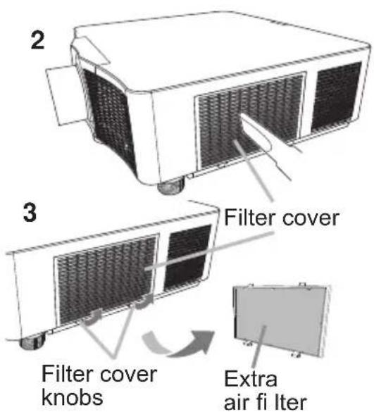
text_image
2 3 Filter cover Filter cover knobs Extra air fi iter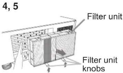
text_image
4, 5 Filter unit Filter unit knobs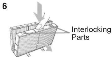
text_image
6 Interlocking Parts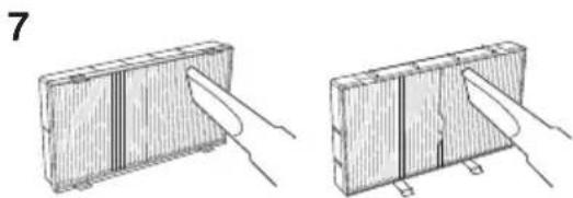
natural_image
Two technical diagrams showing a rectangular component being cut with a tool, no text or symbols presentCleaning and replacing the air filter (continued)
- Put the filter cover back into the place.
- Turn the projector on and reset the filter hours using the FILTER HOURS item in the EASY MENU.
(1) Press the MENU button to display a menu.
(2) Point at the FILTER HOURS using the ▲/▼ cursor buttons, then press the ▶ cursor (or the ENTER / the RESET) button. A dialog appears.
(3) Press the ▶ cursor button to select the "OK" on the dialog. It performs resetting the filter hours.
⚠ WARNING ▶ Before taking care of the air filter, make sure the power cable is not plugged in, then allow the projector to cool sufficiently.
▶ Use only the air filter of the specified type. Do not use the projector without the air filter or the filter cover. It could result in a fire or malfunction to the projector.
▶ Clean the air filter periodically. If the air filter becomes clogged by dust or the like, internal temperatures rise and could cause a fire, a burn or malfunction to the projector.
NOTE • Reset the filter hours only when you have cleaned or replaced the air filter, for a suitable indication about the air filter.
- The projector may display the message such as the "CHECK THE AIR FLOW" or turn off the projector, to prevent the internal heat level rising.
Replacing the internal clock battery
Replace a battery according to the following procedure.
- Turn the projector off, and unplug the power cord. Allow the projector to cool sufficiently.
- After making sure that the projector has cooled adequately, slowly turn over the projector, so that the bottom is facing up.
- Turn the battery cover fully in the direction indicated "OPEN" using a coin, and pick the cover up to remove it.
- Pry up the battery using a fl athead screwdriver to take it out. Do not use any metal tools. While prying it up, put a fi nger lightly on the battery as it may pop out of the holder.
- Replace the battery with a new MAXELL or HITACHI MAXELL, Part No.CR2032 or CR2032H. Slide the battery in under the plastic claw, and push it into the holder until it clicks.
- Replace the battery cover in place, then turn it in the direction indicated "CLOSE" using a coin.
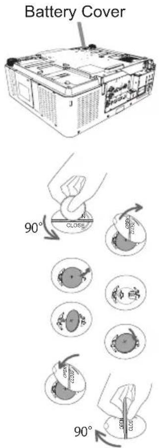
text_image
Battery Cover 90° CLOSE 90°⚠ WARNING ▶ Always handle the batteries with care and use them only as directed. Battery may explode if mistreated. Do not recharge, disassemble or dispose of in fire.
Improper use may result in cracking or leakage, which could result in fire, injury and/or pollution of the surrounding environment.
- Be sure to use only the batteries specified.
• Make sure the plus and minus terminals are correctly aligned when loading a battery. - Keep a battery away from children and pets. If swallowed consult a physician immediately for emergency treatment.
- Do not short circuit or solder a battery.
- Do not allow a battery in a fire or water. Keep batteries in a dark, cool and dry place.
- If you observe battery leakage, wipe out the leakage and then replace a battery. If the leakage adheres to your body or clothes, rinse well with water immediately.
- Obey the local laws on disposing a battery.
Other care
Inside of the projector
To ensure the safe use of your projector, have it cleaned and inspected by your dealer every year.
Caring for the lens
If the lens is flawed, soiled or fogged, it could cause deterioration of display quality. Take care of the lens, being cautious of handling.
- Turn the projector off, and unplug the power cord. Allow the projector to cool sufficiently.
- After making sure that the projector is cool adequately, lightly wipe the lens with a commercially available lens-cleaning wipe. Do not touch the lens directly with your hand.
- Use commercially available lens tissue to clean the lens (used to clean cameras, eyeglasses, etc.).
- If the lens is heavily soiled, wipe it with a cloth moistened with little water.
- Never use polishing agents, detergents, chemicals, or solvents such as benzine or thinner.
- Excepting for lens, use a soft cloth to clean. When excessively soiled, dilute a neutral detergent in water, wet and wring out the soft cloth.
Caring for the cabinet and remote control
Incorrect care could have adverse influence such as discoloration, peeling paint, etc.
- Turn the projector off, and unplug the power cord. Allow the projector to cool sufficiently.
- After making sure that the projector is cool adequately, lightly wipe with gauze or a soft cloth.
If the projector is extremely dirty, dip a soft cloth in water or a neutral cleaner diluted in water, and wipe lightly after wringing well. Then, wipe lightly with a soft, dry cloth.
⚠ WARNING ▶ Make sure the power cord is not plugged in, and allow the projector to cool sufficiently. The high temperature state of the projector could cause a burn and/or malfunction to the projector.
▶ Do not clean or service the inside of the projector. Doing is so dangerous.
▶ Avoid wetting the projector or inserting liquids in the projector. It could result in a fire, an electric shock, and/or malfunction to the projector.
- Do not put anything containing water, cleaners or chemicals near the projector.
- Do not use aerosols or sprays.
⚠️ CAUTION ▶ Incorrect care of the projector could cause not only an injury but adverse influence such as discoloration, peeling paint, etc.
▶ Do not use cleaners or chemicals other than those specified in this manual.
▶ Do not polish or wipe with hard objects.
NOTICE ▶ Do not directly touch the lens surface with hands.
Troubleshooting
If an abnormal operation should occur, stop using the projector immediately.
⚠ WARNING ▶ Never use the projector if abnormal operations such as smoke, strange odor, excessive sound, damaged casing or elements or cables, penetration of liquids or foreign matter, and so on should occur. In such cases, immediately disconnect the power plug from the power outlet. After making sure that the smoke or odor has stopped, contact to your dealer or service company.
If a problem occurs with the projector, the following checks and measures are recommended before requesting repair.
If this does not resolve the problem, contact your dealer or service company. They tell you what warranty condition is applied.
Warnings displayed on the Status Monitor
If an error occurs, a warning is displayed on the Status Monitor (31). Resolve the errors referring to the table of the sections "Related messages" and "Regarding the indicator lamps" when the warning is displayed.
Related messages
When some messages appear, check and deal with it according to the following table. Although these messages automatically disappear after several minutes, they reappear when the power is turned on.
| Message Description | |
 | There is no input signal. Confirm the signal input connection, and the status of the signal source. |
 | Projector is waiting for an image file. Check the hardware connection, settings on the projector and network-related settings. The computer-Projector network connection might be disconnected. Re-connect them. |
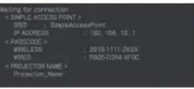 | |
(continued on next page)
Related messages (continued)
| Message Description | |
 | The horizontal or vertical frequency of the input signal is not within the specified range. Confirm the specs for your projector or the signal source specs. |
 | An improper signal is input. Confirm the specs for your projector or the signal source specs. |
 | The internal temperature is rising. Turn the power off, and allow the projector to cool down at least 20 minutes. After having confirmed the following items, turn the power ON again. • Is there blockage of the air passage aperture? • Is the air filter dirty? • Use the unit within the usage temperature parameters (0°C to 40°C or 45°C (User's Manual (concise))). • Is the setting for ALTITUDE appropriate? • Is the exhaust air (hot/cold) from peripheral equipments blowing against the ventilation opening of projector? For details of ALTITUDE, refer to ALTITUDE of SERVICE in the OPTION menu (94). If the projector is used with a wrong setting, it may cause damage to the projector itself or the parts inside. |
(continued on next page)
Related messages (continued)
| Message Description | |
 | A note of precaution when cleaning the air filter.Immediately turn the power off, and clean or change the air filter referring to theCleaning and replacing the air filtersection of this manual. After you have cleaned or changed the air filter, reset the filter timer (76, 111). |
 | The button operation is not available.Check the button you want to use (7). |
Regarding the indicator lamps
The indicators may differ from this manual, check and deal with it according to the following table.
The indicators are described as below.
| LitSteady light | Blinking Off |
Indicator Status Description
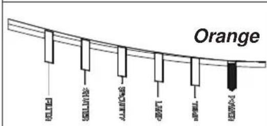
text_image
Orange FLUTTER AVAILLES BEAUTY LAMP TIME POWERThe projector is in a standby state. Refer to the section "Power on/off".
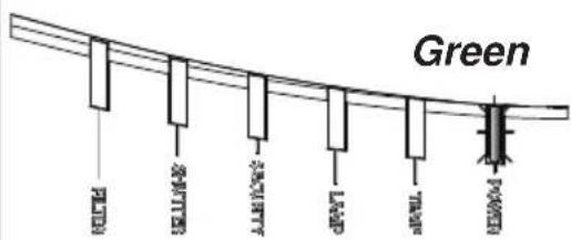
text_image
Green METH SELLING ALLING GRAPY SPRING KONOMThe projector is warming up. Wait for the projector to warm up.
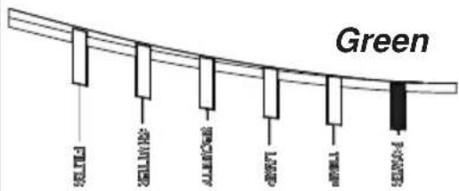
text_image
Green 50000000000000000000000000000000000000000000000000000000000000000000000000000000000000000000000The projector is in an on state. Ordinary operations may be performed.
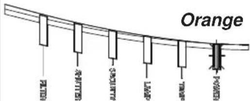
text_image
Orange LED LED LED LED LED LED LED LED LED LEDThe projector is cooling down. Wait for the projector to cool down.
(continued on next page)
Regarding the indicator lamps (continued)
| Indicator Status Description | |
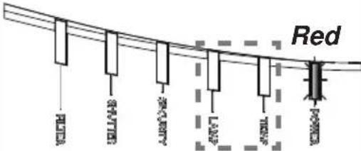 descretionary descretionary | The projector is cooling down. A certain error has been detected.Wait until POWER indicator finishes blinking, and then perform the proper measure using the item descriptions below. |
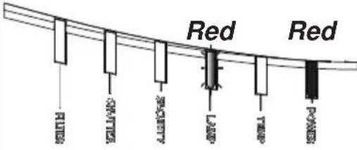 | The lamp cover has not been properly fixed.Turn the power off, and allow the projector to cool down at least 45 minutes. After the projector has sufficiently cooled down, confirm the attachment state of the lamp cover. After performing any needed maintenance, turn the power on again. If the same indication is displayed after the remedy, contact your dealer or service company. |
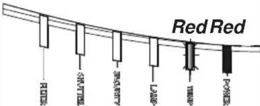 | The cooling fan is not operating.Turn the power off, and allow the projector to cool down at least 20 minutes. After the projector has sufficiently cooled down, confirm that no foreign matter has become caught in the fan, and so on and then turn the power on again.If the same indication is displayed after the remedy, contact your dealer or service company. |
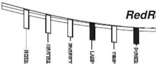 | The lamp does not light, and there is a possibility that interior portion has become heated.Otherwise, AC power supply is unstable (ACBLK).Turn the power off, and allow the projector to cool down at least 20 minutes. After the projector has sufficiently cooled down, confirm the following items, and then turn the power on again.Is there blockage of the air passage aperture?Is the air filter dirty?Use the unit within the temperature range.NORMAL MODE: 0 to 40°CECO MODE: 0 to 45°CIf the same indication is displayed after the remedy, change the lamp referring to the sectionReplacing the lamp. |
(continued on next page)
Regarding the indicator lamps (continued)
| Indicator Status Description | |
| The interior portion has become heated.Turn the power off, and allow the projector to cool down at least 20 minutes. After the projector has sufficiently cooled down, confirm the following items, and then turn the power on again.Is there blockage of the air passage aperture?Is the air filter dirty?Use the unit within the temperature range.NORMAL MODE: 0 to 40°CECO MODE: 0 to 45°CIs the setting for ALTITUDE appropriate?Is the exhaust air (hot/cold) from peripheral equipments blowing against the ventilation opening of projector?For details on ALTITUDE, refer to ALTITUDE of SERVICE in the OPTION menu. If the projector is used with a wrong setting, it may cause damage to the projector itself or the parts inside. | |
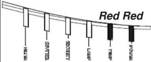 | |
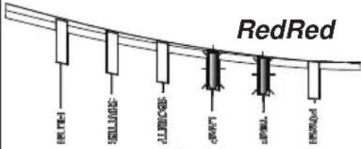 Blinking at the same time Blinking at the same time | It is time to clean the air filter.Turn the power off immediately, and clean or change the air filter referring to the sectionCleaning and replacing the air filter. After cleaning or changing the air filter, reset the filter timer.After the remedy, restart the projector. |
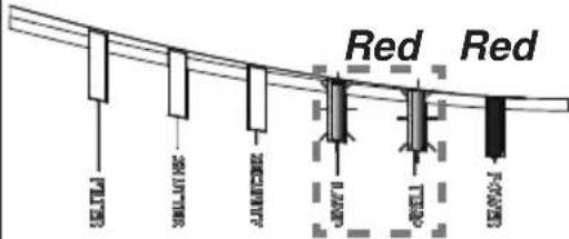 Blinking alternately or Blinking at the same time Blinking alternately or Blinking at the same time | Other error has occurred.Use the unit within the temperature range.NORMAL MODE: 0 to 40°CECO MODE: 0 to 45°CIf the same indication is displayed after the remedy, contact your dealer or service company. |
(continued on next page)
Regarding the indicator lamps (continued)
| Indicator Status Description | |
Orange or Red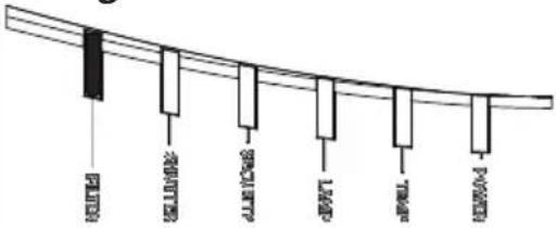 | The air filter is clogged or dirty. (111)Check and clean the air filter.Make sure the power cable is not plugged in, then allow the projector to cool sufficiently.See the section "The interior portion has become heated" (121). |
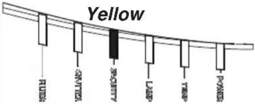 | PIN LOCK function is active.See SECURITY menu > PIN LOCK(104)If the same indication is displayed after the remedy, contact your dealer or service company. |
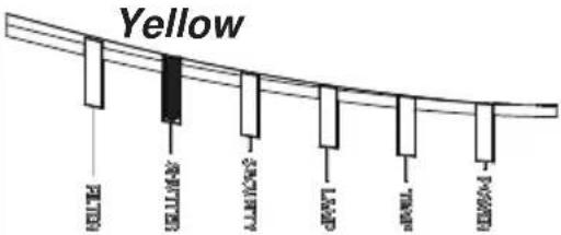 | The mechanical shutter is closed.Press the SHUTTER button on the remote control or on the control panel to open the mechanical shutter. |
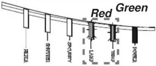 Blinking alternately Blinking alternately | There is a possibility that the interior portion has become overcooled.Use the unit within the temperature range.NORMAL MODE: 0 to 40°CECO MODE: 0 to 45°C |
(continued on next page)
Regarding the indicator lamps (continued)
NOTE • When the interior portion has become overheated, for safety purposes, the projector is automatically shut down, and the indicator lamps may also be turned off. In such a case, disconnect the power cord, and wait at least 45 minutes. After the projector has sufficiently cooled down, confirm the attachment state of the lamp and lamp cover, and turn the power on again.
For the SECURITY indicator, see SECURITY INDICATOR in the SECURITY menu (108).
For the SHUTTER indicator, see the section "Temporarily shading the screen" (52).
The FILTER indicator shows the condition of the air filter. Use this feature to keep the interior of the projector in good condition.
| FILTER indicator Description | |
| Turned off | The air filter is clean.No need to clean up. |
| Lighting In Orange | The air filter is going to be choked.Clean the filter. See the section "The interior portion has become heated" (121). |
| Lighting In Red | The air filter is choked.Turn the power off and clean the air filter immediately. See the section "The interior portion has become heated" (121). |
NOTE • The FILTER indicator might light up in orange or red when something blocks the intake vents even though the air filter is clean.
- The FILTER indicator might light up differently from other indicators or display messages related to cleaning the air filter. Follow the prompt that is displayed earlier.
Resetting all settings
When it is difficult to correct wrong settings, the FACTORY RESET function of SERVICE item in OPTION menu (100) can reset all settings (except settings such as LANGUAGE, AUTO BLANK, LAMP HOURS, FILTER HOURS, FILTER MESSAGE, STANDBY MODE, COMMUNICATION, SECURITY and NETWORK) to the factory default.
Issues that may be easy to be mistaken for machine defects
An issue may be confused with a machine defect, check and deal with it according to the following table.
| Issue Cases | not involving a machine defect | Reference page |
| Power does not come on. | The electrical power cord is not plugged in.Correctly connect the power cord. | 27 |
| The main power source has been interrupted during operation such as by a power outage (blackout), etc.Disconnect the power plug from the power outlet, and allow the projector to cool down at least 10 minutes, then turn the power on again. | 27 | |
| Either there is no lamp and/or lamp cover, or either of these has not been properly fixed.Turn the power off and disconnect the power plug from the power outlet, and allow the projector to cool down at least 45 minutes. After the projector has sufficiently cooled down, confirm the attachment state of the lamp and lamp cover, and then turn the power on again. | 109 | |
| Neither sounds nor pictures are output. | The signal cables are not correctly connected.Correctly connect the connection cables. | 13 ~ 22 |
| Signal source does not correctly work.Correctly set up the signal source device by referring to the manual of the source device. | - | |
| The input changeover settings are mismatched.Select the input signal, and correct the settings. | 38 | |
| AV MUTE function is working.Press AV MUTE button on the remote control. | 37 | |
| Sound does not come out. | The signal cables are not correctly connected.Correctly connect the audio cables. | 13 ~ 22 |
| The volume is adjusted to an extremely low level.Adjust the volume to a higher level using the menu function or the remote control. | 37, 80 | |
| The AUDIO SOURCE/SPEAKER setting is not correct.Correctly set the AUDIO SOURCE/SPEAKER in AUDIO menu. | 80 | |
| The Sound button (♪) or checkbox is disabled.If you have selected LAN, remove the checkmark from the Sound checkbox in the Option menu of LiveViewer. | - | |
| No pictures are displayed. | The signal cables are not correctly connected.Correctly connect the connection cables. | 13 ~ 22 |
| The brightness is adjusted to an extremely low level.Adjust BRIGHTNESS to a higher level using the menu function. | 62 | |
| The computer cannot detect the projector as a plug and play monitor.Make sure that the computer can detect a plug and play monitor using another plug and play monitor. | 13 | |
| The shutter is closed.Check whether the SHUTTER indicator is blinking. If it is blinking, press SHUTTER button on the control panel. | 52 | |
| The remote control does not work. | The batteries in the remote control are near the end. Replace the batteries. | 28 |
| The ID numbers set in the projector and the remote control are different. Press the ID button with the same ID number as the projector, then perform the desired operation. The ID number set in the projector can be displayed by pressing any of the ID buttons on the remote control for three seconds while the lamp is on. | 29 | |
| Video screen display freezes. | The FREEZE function is working. Press FREEZE button to restore the screen to normal. | 52 |
| Colors have a faded-out appearance, or color tone is poor. | Color settings are not correctly adjusted. Perform picture adjustments by changing the COLOR TEMP, COLOR and/or TINT settings, using the menu functions. | 62, 64 |
| COLOR SPACE setting is not suitable. Change the COLOR SPACE setting to AUTO, RGB, SMPTE240, REC709 or REC601. | 69 | |
| Pictures appear dark. | The brightness and/or contrast are adjusted to an extremely low level. Adjust BRIGHTNESS and/or CONTRAST settings to a higher level using the menu function. | 62 |
| The projector is operating in Eco mode. Set ECO MODE in the LAMP & FILTER menu to NORMAL. | 75 | |
| The lamp is approaching the end of its product lifetime. Replace the lamp. | 109 | |
| Pictures appear blurry. | The lens cover is attached. Remove the lens cover. | - |
| Either the focus and/or horizontal phase settings are not properly adjusted. Adjust the focus using the FOCUS + / - buttons, and/or H PHASE using the menu function. | 41, 68 | |
| Issue Cases not involving a machine defect | Reference page | |
| Pictures appear blurry. (continued) | The lens is dirty or misty. Clean the lens referring to the section Caring for the lens. | 114 |
| Some kind of image degradation such as flickering or stripes appear on screen. | When the projector is operating in Eco mode, flickering may appear on screen. Set ECO MODE in the LAMP & FILTER menu to NORMAL. | 75 |
| The OVER SCAN ratio is too big. Adjust OVER SCAN in the SIZE AND POSITION menu smaller. | 67 | |
| Excessive VIDEO NR. Change the setting of VIDEO NR in the INPUT menu. | 69 | |
| The FRAME LOCK function cannot work on the current input signal. Set FRAME LOCK in the INPUT menu to OFF. | 71 | |
| RS-232C does not work. | The POWER SAVE function is working. Select NORMAL for STANDBY MODE item in the SETUP menu. | 78 |
| The COMMUNICATION TYPE for the CONTROL port is set to NETWORK BRIDGE. Select OFF for COMMUNICATION TYPE item in the OPTION - SERVICE - COMMUNICATION menu. | 97 | |
| Network does not work. | The POWER SAVE function is working. Select NORMAL for STANDBY MODE item in the SETUP menu. | 78 |
| The same network address is set for both wireless and wired LAN. Change the network address setting for wireless or wired LAN. | - | |
| Issue Cases | not involving a machine defect | Reference page |
| The IR and RS-232C does not work on HDBase T^TM connection. | The POWER SAVE function is working.Select NORMAL for STANDBY MODE item in the SETUP menu. | 78 |
| HDBaseT connection does not work. | The POWER SAVE function is working.Select NORMAL for STANDBY MODE item in the SETUP menu. | 78 |
| The connected equipment may not be supported by HDBaseT.Refer to User's manual (detailed) for connection. | 14 | |
| IR and LAN does not work via HDBaseT. | Check if the IR setting is OFF under HDBaseT.EASY MENU > ADVANCED MENU > OPTION > SERVICE > REMOTE RECEIV. | 96 |
| Check if the LAN setting is HDBaseT.EASY MENU > ADVANCED MENU > NETWORK > WIRED NETWORK | - | |
| LAN does not work, if LAN is connected to the projector while having an input signal from HDBaseT. | Check if the LAN setting is HDBaseT.EASY MENU > ADVANCED MENU > NETWORK > WIRED NETWORK | - |
| This projector is compatible with 100BASE-T only.Check the specification of the connected equipments. | - | |
| If the LAN cable is connected with the hub, try to change the connected port at the hub | - | |
| If the LAN cable is connected directly to the computer, try to connect to other computer | - | |
| No image is displayed via HDBaseT. | Check the LAN cable if it is CAT5e certified or higher. | - |
| Try to change the LAN cable. | - | |
| If the LAN cable is connected with more than three extension connector, the transmission of 100 meters may fail. | - | |
| Check if the extension connector is compatible with CAT5e.All LAN cable and extension connector connected with HDBaseT port must be CAT5e certified. | - | |
| Issue Cases not involving a machine defect | Reference page | |
| No image is displayed via SDI. (LWU720i/ LHD720i only). | Check if it is connected with a cable of 5CFB or greater, or Belden 1694A or greater. | - |
| Check if a cable with a length of 100m or less is used. | - | |
| Try to change the cable. | - | |
| Check if a supported signal format is input. | - | |
| No image is displayed via DisplayPort. | Check if DisplayPort cables conforming to the DisplayPort standard is used for connection. | - |
| When the projector is connected to the computer with an early type of chipset or graphics card that supports the DisplayPort, the projector and/or computer may not operate normally. | - | |
| The problem may be solved by upgrading the driver of graphic accelerator of the computer to the latest version. | - | |
| Turn off the projector and the external device, and turn on again. | - | |
| Check if the supported signal format is input. | - | |
| NETWORK BRIDGE function does not work. | The NETWORK BRIDGE function is turned off. Select NETWORK BRIDGE for COMMUNICATION TYPE item in the OPTION - SERVICE - COMMUNICATION menu. | 97 |
| Schedule function does not work. | The POWER SAVE function is working. Select NORMAL for STANDBY MODE item in the SETUP menu. | 78 |
| The internal clock has been reset. Once you turn off the projector in the POWER SAVE mode or the AC power, the current date and time setting is reset. Check the DATE AND TIME setting for WIRELESS SETUP or WIRED SETUP in the NETWORK menu. | - | |
| Issue Cases | not involving a machine defect | Reference page |
| When the projector is connected to the network, it powers off and on as described below.Powers off↓POWERindicator blinks in orange a few times↓Goes into standby mode | Disconnect the LAN cable and check that the projector is working properly.If this issue occurs after connecting to the network, there may be a loop between two Ethernet switching hubs within the network.- Two or more Ethernet switching hubs are in a network.- Two of the hubs are doubly connected by LAN cables.- This double connection forms a loop between the two hubs.Such a loop may have an adverse effect on the projector as well as the other network devices.Check the network connection and remove the loop by disconnecting the LAN cables such that there is only one connecting cable between two hubs. | - |
NOTE • Although bright spots or dark spots may appear on the screen, this is a unique characteristic of liquid crystal displays, and it does not constitute or imply a machine defect.
Specifications
See the Specifications in the Setup Guide which is a book.
End User License Agreement for the Projector Software
- Software in the projector consists of the plural number of independent software modules and there exist our copyright or/and third party copyrights for each of such software modules.
- Read "End User License Agreement for the Projector Software" which is separated document.
Corporate offices
USA-Cypress
ph:714-236-8610
Canada - Kitchener
ph:519-744-8005
Consultant offices
Italy
ph:+39(0)299021161
Worldwide offices
Australia
ph:+61(0)736244888
Brazil
ph:+55(11)25484753
China(Beijing)
ph:+861065610240
China(Shanghai)
ph:+86 21 6278 7708
Eastern Europe and
Russian Federation
ph:+36(0)14748100
France
ph:+33(0)141214404
Germany
ph: +49 2161 664540
India
ph:+91(080)67089999
Japan
ph:81-3-3599-7481
Korea (Seoul)
ph:+82 2 702 160
Republic of South Africa
ph:+27(0)115100094
Singapore
ph:+656877-8737
Spain
ph:+34916339990
United Arab Emirates
ph:+97143206688
United Kingdom
ph:+441189778000