AW900x - Wi-Fi Router AvaLAN - Free user manual and instructions
Find the device manual for free AW900x AvaLAN in PDF.

User questions about AW900x AvaLAN
0 question about this device. Answer the ones you know or ask your own.
Ask a new question about this device
Download the instructions for your Wi-Fi Router in PDF format for free! Find your manual AW900x - AvaLAN and take your electronic device back in hand. On this page are published all the documents necessary for the use of your device. AW900x by AvaLAN.
USER MANUAL AW900x AvaLAN
natural_image
Exterior view of a mechanical or scientific device with a vertical axis antenna and a base-mounted device (no visible text or symbols)AW900x
USER'S MANUAL
Point-to-point
Industrial-grade, ultra-long-range 900 MHz non-line-of-sight wireless Ethernet systems
Non-line-of-sight :: 900 MHz
Thank you for your purchase of the AW900x point-to-point wireless Ethernet bridge.
If you have any questions when configuring your AvaLAN system, please send an e-mail to support@avalanwireless.com.
For a live technician, please call technical support at (650) 384-0000.
For advanced installation information, please visit www.avalanwireless.com.
text_image
AVOLIAN WEEFRENSE
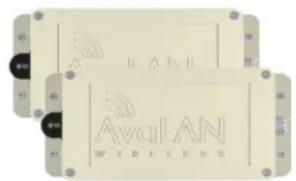
natural_image
Two white RF switch devices connected to black cables, no visible text or symbolsAW900x Kit
Long-range 900 MHz wireless outdoor Ethernet bridge. Kit includes:
■ (2) AW900x outdoor radios
■ (2) 110 VAC to 12 VDC power adapters
■ (2) Power over Ethernet injectors
Requires antennae: Use with AW2, AW5H-900, AW5P-900, AW6, AW10, AW11, or AW15 — all FCC approved
Operational summary
The AW900x replaces costly wiring with a wireless Ethernet bridge that can enable remote Wi-Fi access points, Ethernet pan/tilt/zoom security cameras, VoIP phones, or Internet kiosks. AvaLAN's product offers the ideal combination of price, range, data rate, security, interference avoidance, quality-of-service, and ease-of-use.
The AW900x is the best solution when:
- a Broadband Ethernet drop will cost too much or is impractical to install
- guaranteed DSL-rate throughput is required (kiosks/Wi-Fi access points/PTZ cameras)
- guaranteed latency for voice or video is required (PTZ cameras/VolP)
■ Wi-Fi is too slow due to saturation or 2.4 GHz interference (airport/mall/PTZ cameras)
■ ultra-low current consumption is required (1 Watt/solar powered systems)
Features include:
foliage penetrating, non-line-of-sight wireless Ethernet bridging does not interfere with Wi-Fi networks
- Highest Quality of Service (QoS) available — synchronous point-to-point protocol enables extremely low data latency and jitter
- 128 bit encrypted payload protection provides secure data delivery
- simple plug and play – pre-configured as matched pairs with no user programming required power over Ethernet enabled
■ operates in the 902-928 MHz band and does not require an FCC license to operate or install VLAN extensions supported
Quick setup
1) Plug in the AW900x using the supplied injector and power adapter.
2) Connect an Ethernet cable from each AW900x to a network device.
3) Send Ethernet traffic. For troubleshooting, see Page 4.
System diagram
Each AW900x radio automatically selects the best radio channel, encrypts the Ethernet traffic, and transports the data wirelessly to its mate. Any Ethernet device can be connected to the AW900x. The AW900x functions in place of an Ethernet cable and provides a transparent wireless point-to-point Ethernet cable replacement. Crossover cables are not necessary as the AW900x automatically senses the device (client or switch).

text_image
Power adapter 110 VAC Power over Ethernet injector Data CAT5 cable (not included) Ethernet RJ45/10BaseT AW900x RF connector RP-TNC Power 9 to 48 VDC 900 MHz digital Ethernet bridge AFW900x RF connector RP-TNC Ethernet RJ45/10BaseT CAT5 cable (not included) CAT5 cable (not included) Data Power adapter 110 VAC Power over Ethernet injector Power 9 to 48 VDCLED display
| Name | Function | Color |
| Power | Unit has power and has successfully booted. | Red |
| RF Link | The radio has successfully synchronized with it partner. | Green |
| RF TX | Radio transmission is occurring. | Green |
| RF RX | Radio reception is occurring. | Green |
| Eth Link | The Ethernet Port has a valid Ethernet connection | Green |
| Activity | The AW900m is processing data | Green |
| 1 (channel) | By adding the numbers that are lit the user can determine the current radio channel. | Green |
| 2 (channel) | ||
| 4 (channel) | 1 903.12500 MHz 7 915.62500 MHz2 905.20833 MHz 8 917.70833 MHz3 907.29167 MHz 9 919.79167 MHz4 909.37500 MHz 10 921.87500 MHz5 911.45833 MHz 11 923.95833 MHz6 913.54167 MHz 12 926.04167 MHz | |
| 8 (channel) | ||
| Link Quality Meter | Excellent link quality -No retransmissions | Green |
| Very good link quality -Few retransmissions | Green | |
| Good link quality -Occasional retransmissions | Amber | |
| The more LEDs that are lit the higher the link quality. | Fair link quality -Some retransmissions | Amber |
| Poor link quality -Many retransmissions | Red | |
| No link qualityNo link available | Red |
Troubleshooting
See the online installation tutorial and FAQ at www.avalanwireless.com.
No Power LED
Check the power connections.
No Radio Link LED
The radio is looking for its matched partner. If both units are powered up and the Power LEDs are active, they may be too far away to create the radio connection. Try other locations that may have a less obstructed path or try to reorient the antennae. Yagi type antennae get their best range when they are oriented to point directly at each other with the antenna elements oriented in the same place (eg. vertically or horizontally).
Radio LINK LED is on but Link Quality Indicator is low
The units may be too far away to create a good radio connection. Try other locations that may have a less obstructed path, or try to reorient the antennae.
No Ethernet LINK LED
Check your network connections.
Installing multiple systems in close proximity
See the online installation tutorial and FAQ at www.avalanwireless.com
Still not working?
Temporarily use an Ethernet cable to see if the network is working over a wired connection. If an Ethernet cable does not work then the problem is with the network.
Advanced settings
Automatic frequency selection mode (DIP switches — all OFF for automatic mode)
The AW900x is designed to automatically select and continuously optimize the performance of its radio channel. The radio channel is monitored to ensure it is providing low error rates necessary for successful radio transmission. In the event that the error rate rises, the AW900x will autonomously change to a new channel. There are 12 non-overlapping channels.
Manual frequency selection mode
To restrict the operation of the AW900x to a subset of the 902-928 band, the user may activate a manual selection mode that allows the radio to automatically choose the best channel within a grouped subset of the 12 available channels. This is enabled by the 8 position DIP switch on the master unit. These settings allow the AW900x to operate on the optimal channel in one of three subsets, LOW 4, MID 4, or HIGH 4. The DIP switch settings are:
| Channels | DIP Setting | Frequency |
| LOW 4 - 1,2,3 or 4 | 2 On / 3 Off | 902-910 MHz |
| MID 4 - 5,6,7 or 8 | 2 Off / 3 On | 910-918 MHz |
| HIGH 4 - 9,10,11 or 12 | 2 On / 3 On | 918-927 MHz |
Or, the user may wish to select a specific channel. This can be done by setting DIP switches 5-8 as shown in the table below (turn DIP 2 Off / 3 Off).
| Channel | DIP Setting | Center Frequency |
| 1 | 5 On / 6 Off / 7 Off / 8 Off | 903.12500 MHz |
| 2 | 5 Off / 6 On / 7 Off / 8 Off | 905.20833 MHz |
| 3 | 5 On / 6 On / 7 Off / 8 Off | 907.29167 MHz |
| 4 | 5 Off / 6 Off / 7 On / 8 Off | 909.37500 MHz |
| 5 | 5 On / 6 Off / 7 On / 8 Off | 911.45833 MHz |
| 6 | 5 Off / 6 On / 7 On / 8 Off | 913.54167 MHz |
| 7 | 5 On / 6 On / 7 On / 8 Off | 915.62500 MHz |
| 8 | 5 Off / 6 Off / 7 Off / 8 On | 917.70833 MHz |
| 9 | 5 On / 6 Off / 7 Off / 8 On | 919.79167 MHz |
| 10 | 5 Off / 6 On / 7 Off / 8 On | 921.87500 MHz |
| 11 | 5 On / 6 On / 7 Off / 8 On | 923.95833 MHz |
| 12 | 5 Off / 6 Off / 7 On / 8 On | 926.04167 MHz |
Site survey mode (DIP switch 4 - default is OFF for normal operation)
In this mode, the AW900x can perform a site survey. With this mode activated, the radios send and receive at 100 percent capacity by transceiving self-generated simulated data. The installer can monitor the Link Quality display to assess channel quality while optimizing antennae orientation. The installer can manually select each channel to evaluate performance and identify the best channels for operation. By identifying channels with poor performance it is possible to identify possible interferers and use “manual frequency selection mode” to avoid portions of the band or select a fixed operating frequency.
Note: Ethernet traffic does not get transported while the radios are in this mode.
Power save mode (DIP switch 1 - default is OFF for normal LED display)
In this mode, the display LEDs can be turned off for low power applications (solar).
Technical specifications
CHARACTERISTIC SPECIFICATION / DESCRIPTION
| RF transmission rate | 1.536 Mb/s |
| Ethernet throughput | 935 Kb/s |
| Output power | +21 dBm (4 Watts EIRP used with 15 dBi antenna) |
| Receive sensitivity | -112 dBm at 10e-4 BER with 15 dBi antenna |
| Latency | < 2 ms – assuming a dedicated wireless link to client device |
| Jitter | ±0.5 ms – depending on packet size, interference, and SNR |
| Power consumption | FX 0.6 W, TX 1.4 W |
| Voltage | 4 to 48 VDC |
| Radio channels | 12 non-overlapping |
| Automatic frequency select | Yes – radio channel automatically selected and adaptively optimized |
| Manual frequency mode | Yes |
| Status LEDs | Power, Ethernet Link, RF RX, RF TX, 4/Channel, and 6/Link Quality |
| MAC pass-through filter | Yes – can be disabled |
| Error correction technique | Sub-block error detection and retransmission |
| Adjacent-band rejection | SAW receiver filter attenuates cellular and pager interference |
| Enclosure type | NEMA 4X |
| Temperature range | -40°C to 70°C |
| Power over Ethernet | Includes injectors/power supplies – 9 to 48 VDC ready |
Range

line
| Outdoor Range (FT) | Actual Throughput (MBIT/S) | | ----------------- | -------------------------- | | 250 | 802.11 | | 500 | 3.5 | | 1000 | 3.5 | | 2000 | 3.5 | | 10000 | 3.5 | | 2500 | 3.5 | | 5000 | 3.5 | | 10000 | 3.5 | | 2500 | 3.5 | | 5000 | 3.5 | | 10000 | 3.5 | | 2500 | 3.5 | | 5000 | 3.5 | | 2500 | 3.5 | | 5000 | 3.5 | | 10000 | 3.5 | | 2500 | 3.5 | | 5000 | 3.5 | | 2500 | 3.5 | | 5000 - Longest-range wireless Ethernet solution | 1.0 | | 1100 | 1.0 | | 1500 | 1.0 |Warranty
This product is warranted to the original purchaser for normal use for a period of 180 days from the date of purchase. If a defect covered under this warranty occurs, AvaLAN will repair or replace the defective part, at its option, at no cost. This warranty does not cover defects resulting from misuse or modification of the product.
Compliance Statement (Part 15.19)
This device complies with Part 15 of the FCC Rules.
Operation is subject to the following two conditions:
-
This device may not cause harmful interference, and
-
This device must accept any interference received, including interference that may cause undesired operation.
Warning ( Part 15.21 )
Changes or modifications not expressly approved by the party responsible for compliance could void the user's authority to operate the equipment.
RF Exposure (OET Bulletin 65)
To comply with FCC RF exposure requirements for mobile transmitting devices, this transmitter should only be used or installed at locations where there is at least 20cm separation distance between the antenna and all persons.
Information to the User - Part 15.105 (b)
Note: This equipment has been tested and found to comply with the limits for a Class B digital device, pursuant to part 15 of the FCC Rules. These limits are designed to provide reasonable protection against harmful interference in a residential installation. This equipment generates, uses and can radiate radio frequency energy and, if not installed and used in accordance with the instructions, may cause harmful interference to radio communications. However, there is no guarantee that interference will not occur in a particular installation. If this equipment does cause harmful interference to radio or television reception, which can be determined by turning the equipment off and on, the user is encouraged to try to correct the interference by one or more of the following measures:
--Reorient or relocate the receiving antenna.
--Increase the separation between the equipment and receiver.
--Connect the equipment into an outlet on a circuit different from that to which the receiver is connected.
--Consult the dealer or an experienced radio/TV technician for help.
Sample applications
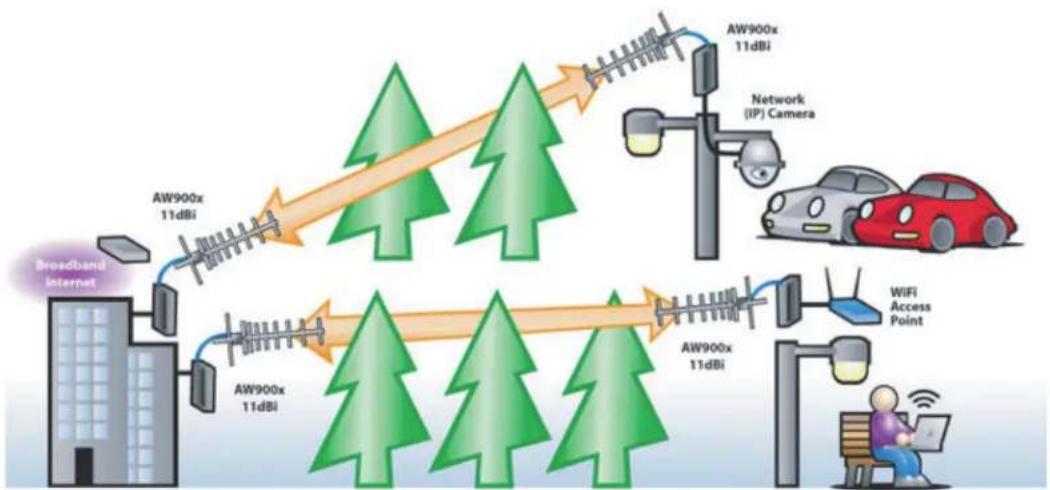
flowchart
graph LR
    A["Broadband Internet"] --> B["Network Camera"]
    B --> C["Network (IP) Camera"]
    C --> D["AW900x 11dBi"]
    D --> E["AW900x 11dBi"]
    E --> F["AW900x 11dBi"]
    F --> G["WiFi Access Point"]
    G --> H["Person using laptop"]
    style A fill:#f9f,stroke:#333
    style B fill:#ccf,stroke:#333
    style C fill:#cfc,stroke:#333
    style D fill:#fcc,stroke:#333
    style E fill:#cff,stroke:#333
    style F fill:#ffc,stroke:#333
    style G fill:#fcc,stroke:#333
    style H fill:#fff,stroke:#333
support@avalanwireless.com
Technical support :: (650) 384.0000
For advanced installation information visit www.avalanwireless.com
©2004 – 2007 AvaLAN Wireless Systems Incorporated. All rights reserved. AvaLAN Wireless and the AvaLAN Wireless logo are registered trademarks of AvaLAN Wireless Systems Incorporated. All other trademarks are property of their respective owners. AvaLAN Wireless makes no representations or warranties with respect to the accuracy, utility, or completeness of the contents of this publication and reserves the right to make changes to specifications and product descriptions at any time without notice. No license, express or implied, by estoppel or otherwise, to any patents or other intellectual property rights is granted by this document. Particular uses or applications may invalidate some of the specifications and/or product descriptions contained herein. The customer is urged to perform its own engineering review before deciding on a particular application. AvaLAN Wireless products are not designed for use in medical, life saving, or life sustaining applications. 07.07.2007