button
Use this button to temporarily turn off the image page 38)
(13) ▲▼◀▶ buttons
Use these buttons to select menu items, change settings, and adjust levels. It is also used to enter the [SECURITY] password.
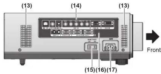
Terminals on side

(1) LAN terminal
This is a terminal to connect to the network.
(2) VIDEO input terminal
(7) REMOTE 1 IN terminal /REMOTE 1 OUT terminal These are the terminals to connect the remote control for serial control when the system uses multiple projectors.
(8) REMOTE 2 IN terminal
This is a terminal to remotely control the projector using the external control circuit.
(9) SERIAL IN terminal
This is a RS-232C compatible terminal to externally control the projector by connecting a computer.
(10) SERIAL OUT terminal
This is a terminal to output the signal connected to the SERIAL IN terminal.
Attention
- Connect the LAN to the indoor equipment.
Using Remote control
Inserting and removing the batteries
1) Open the cover.
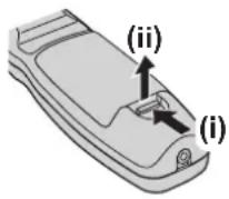
2) Insert the batteries and close the cover (insert the ⬤ side first).
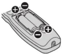
natural_image
Diagram of a remote control casing with battery and indicator lights (no text or symbols)
- When remove the batteries, perform the steps in the reverse order.
Setting Remote control ID numbers
When you use the system with multiple projectors, you can operate all the projectors simultaneously or each projector individually using single remote control, if a unique ID number is assigned to each projector. After setting the ID number of the projector, set same ID number on the remote control.
The ID number of the projector is set to [ALL] by the factory default. When using a single projector, press the button on the remote control.
How to set
1) Press the button on the remote control.
2) Within five seconds, press the two-digit ID number set on the projector using the number (<0> - <9>) button.
Attention
- Since setting of the ID number on the remote control can be performed even without the projector, do not press the button carelessly. If the number (<0> - <9>) button is not pressed within five seconds after the button is pressed, the ID number returns to that before pressing the button.
- The ID number set on the remote control will be stored unless it is set again. However, it will be erased if the remote control is left with dead batteries. Set the same ID number again when the batteries are replaced.
Note
- Set the ID number of the projector from the [PROJECTOR SETUP] menu [PROJECTOR ID] (→ page 61).
Connecting to the projector with a cable
When you use the system with multiple projectors, configure the units as in the following figure. Use a commercial M3 stereo mini jack cable and connect the other devices to the / terminals of the projector.
It is effective to use the remote control in a place where an obstacle stands in the light path or where devices are susceptible to the outside light.
Connecting terminals
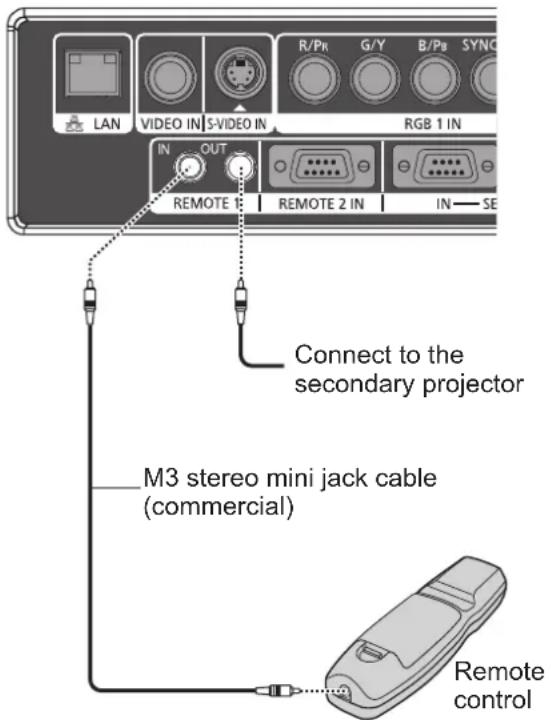
Connect to the remote control wired terminal
Attention
- Use a cable that is 15 m or shorter, with 2 core shield. The remote control may not operate when the length of the cable exceeds 15 m or when the shielding of the cable is inadequate.
Setting up
Projection method
You can use the projector with any of the following four projection methods. Select the appropriate method depending on the environment.
■Mounting on the ceiling and projecting forward
natural_image
Illustration of a projector screen projecting onto a person using a smartphone (no text or symbols)
| Menu item*1 | Method |
| [PROJECTION METHOD] | [FRONT/CEILING] |
| [COOLING CONDITION] | [CEILING SETTING] |
■Setting on a desk/floor and projecting from rear
(Using the translucent screen)

natural_image
Simple line drawing of a box and a seated person (no text or symbols)
| Menu item*1 | Method |
| [PROJECTION METHOD] | [REAR/FLOOR] |
| [COOLING CONDITION] | [FLOOR SETTING] |
■Mounting on the ceiling and projecting from rear
(Using the translucent screen)
| Menu item*1 | Method |
| [PROJECTION METHOD] | [REAR/CEILING] |
| [COOLING CONDITION] | [CEILING SETTING] |
■Setting on a desk/floor and projecting forward
| Menu item*1 | Method |
| [PROJECTION METHOD] | [FRONT/FLOOR] |
| [COOLING CONDITION] | [FLOOR SETTING] |
*1: For details of the menu items, confirm from the [PROJECTOR SETUP] menu → [PROJECTION METHOD] (→ page 61) and [COOLING CONDITION] (→ page 62).
Parts for ceiling mount (optional)
You can install the projector on the ceiling using the optional ceiling mount bracket (ET-PKD56H: for high ceilings, ET-PKD55S: for low ceilings).
- Use only the ceiling mount brackets specified for this projector.
- Refer to the installation manual for the ceiling mount bracket when you install the bracket and the projector.
Attention
- To ensure the projector performance and security, installation of the ceiling mount bracket must be carried out by your dealer or a qualified technician.
Setting up
Screen size and throw distance
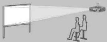
Install the projector referring to the following figures and table describing projection distances. Image size and image position can be adjusted in accordance with the screen size and screen position.
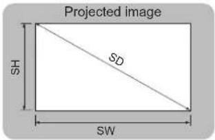
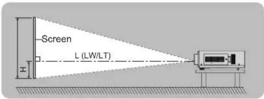

| L (LW/LT)1 | Projection distance (m) |
| SH Image | height (m) |
| SW Image | width (m) |
| H | Distance from the center of lens to the image lower end (m) |
| SD Image | diagonal size (m) |
*1: LW: Minimum projection distance when the zoom lens is used
LT: Maximum projection distance when the zoom lens is used
Attention
- Read "Precautions for Use" (→ pages 12 to 16) before installation.
- Do not use the projector and the high-powered laser equipment in the same room. Hitting of a laser beam on to the lens can damage the DLP chips.
■Projection distance per projection lens (for PT-DW730U)
- When the screen aspect ratio is 16:10 (unit: m)
(All measurements below are approximate and may differ slightly from the actual measurements.)
| Lens type | Standard zoom lens | Optional lens | Height position (H)2 |
| Fixed-focus lens | Ultra short-focus zoom lens | Short-focus zoom lens | Medium-focus zoom lens | Long-focus zoom lens | Ultra long-focus zoom lens |
| Projection lens Model No. - | | ET-DLE055 | ET-DLE080 | ET-DLE150 | ET-DLE250 | ET-DLE350 | ET-DLE450 |
| Throw ratio*1 | 1.8-2.5:1 | 0.8:1 | 0.8-1.0:1 | 1.4-2.0:1 | 2.4-3.8:1 | 3.8-5.7:1 | 5.6-9.0:1 |
| Projection size Projection distance (L) |
| Screen size (SD) | Height (SH) | Width (SW) | Min. | Max. Fixed | Min. Max. | Max. Min. | Max. Min. | Min. Max. | Max. Min. | Max. Min. | Max. Min. | Max. Min. | Max. Min. | Max. Min. | Max. Min. |
| 1.27 (50") | 0.673 | 1.077 | 1.91 | 2.70 | 0.87 | 0.87 | 1.09 | 1.45 | 2.12 | 2.54 | 4.06 | 4.00 | 6.11 | 5.96 | 9.60 | -0.07-0.34 |
| 1.52 (60") | 0.808 | 1.292 | 2.31 | 3.26 | 1.06 | 1.05 | 1.32 | 1.75 | 2.55 | 3.07 | 4.89 | 4.83 | 7.36 | 7.21 | 11.57 | -0.08-0.40 |
| 1.78 (70") | 0.942 | 1.508 | 2.71 | 3.81 | 1.24 | 1.24 | 1.54 | 2.05 | 2.98 | 3.59 | 5.72 | 5.65 | 8.61 | 8.46 | 13.55 | -0.09-0.47 |
| 2.03 (80") | 1.077 | 1.723 | 3.11 | 4.37 | 1.42 | 1.42 | 1.77 | 2.35 | 3.42 | 4.12 | 6.55 | 6.48 | 9.86 | 9.71 | 15.53 | -0.11-0.54 |
| 2.29 (90") | 1.212 | 1.939 | 3.50 | 4.92 | 1.61 | 1.60 | 2.00 | 2.65 | 3.85 | 4.64 | 7.38 | 7.31 | 11.11 | 10.96 | 17.51 | -0.12-0.61 |
| 2.54 (100") | 1.346 | 2.154 | 3.90 | 5.48 | 1.79 | 1.78 | 2.22 | 2.95 | 4.28 | 5.17 | 8.20 | 8.13 | 12.36 | 12.22 | 19.49 | -0.14-0.67 |
| 3.05 (120") | 1.615 | 2.585 | 4.70 | 6.59 | 2.16 | 2.15 | 2.68 | 3.55 | 5.15 | 6.21 | 9.86 | 9.79 | 14.86 | 14.72 | 23.45 | -0.16-0.81 |
| 3.81 (150") | 2.019 | 3.231 | 5.89 | 8.25 | 2.71 | 2.70 | 3.36 | 4.45 | 6.45 | 7.79 | 12.35 | 12.27 | 18.61 | 18.47 | 29.38 | -0.20-1.01 |
| 5.08 (200") | 2.692 | 4.308 | 7.88 | 11.03 | 3.63 | 3.62 | 4.49 | 5.95 | 8.61 | 10.41 | 16.49 | 16.40 | 24.85 | 24.73 | 39.28 | -0.27-1.35 |
| 6.35 (250") | 3.365 | 5.385 | 9.86 | 13.81 | - | 4.53 | 5.62 | 7.45 | 10.78 | 13.03 | 20.63 | 20.53 | 31.10 | 30.99 | 49.17 | -0.34-1.68 |
| 7.62 (300") | 4.039 | 6.462 | 11.85 | 16.58 | - | 5.45 | 6.76 | 8.96 | 12.95 | 15.65 | 24.77 | 24.67 | 37.35 | 37.25 | 59.06 | -0.40-2.02 |
| 8.89 (350") | 4.712 | 7.539 | 13.84 | 19.36 | - | 6.36 | 7.89 | 10.46 | 15.11 | 18.28 | 28.91 | 28.80 | 43.59 | 43.51 | 68.96 | -0.47-2.36 |
| 10.16 (400") | 5.385 | 8.616 | 15.83 | 22.13 | - | 7.28 | 9.02 | 11.96 | 17.28 | 20.90 | 33.06 | 32.94 | 49.84 | 49.76 | 78.85 | -0.54-2.69 |
| 12.70 (500") | 6.731 | 10.770 | 19.80 | 27.68 | - | 9.11 | 11.29 | 14.96 | 21.61 | 26.14 | 41.34 | 41.20 | 62.33 | 62.28 | 98.64 | -0.67-3.37 |
| 15.24 (600") | 8.077 | 12.923 | 23.78 | 33.23 | - | 10.94 | 13.56 | 17.96 | 25.94 | 31.39 | 49.62 | 49.47 | 74.82 | 74.80 | 118.43 | -0.81-4.04 |
*1: The throw ratio is based on the value during projection onto a 2.03-m (80") screen size.
*2: When the fixed-focus lens (ET-DLE055) is attached, the lens shift cannot be used, so the height position (H) will be SH/2.
- When the screen aspect ratio is 16:9 (unit: m)
(All measurements below are approximate and may differ slightly from the actual measurements.)
| Lens type | Standard zoom lens | Optional lens | Height position (H)2 |
| Fixed-focus lens | Ultra short-focus zoom lens | Short-focus zoom lens | Medium-focus zoom lens | Long-focus zoom lens | Ultra long-focus zoom lens |
| Projection lens Model No. - | | ET-DLE055 | ET-DLE080 | ET-DLE150 | ET-DLE250 | ET-DLE350 | ET-DLE450 |
| Throw ratio*1 | 1.8–2.5:1 | 0.8:1 | 0.8–1.0:1 | 1.4–2.0:1 | 2.4–3.8:1 | 3.8–5.7:1 | 5.6–9.0:1 |
| Projection size Projection distance (L) |
| Screen size (SD) | Height (SH) | Width (SW) | Min. | Max. | Fixed Min. | Max. | Min. Max. | Max. Min. | Max. Min. | Max. Max. | Max. | Max. | | | |
| 1.27 (50") | 0.623 | 1.107 | 1.97 | 2.78 | 0.90 | 0.89 | 1.12 | 1.49 | 2.18 | 2.62 | 4.18 | 4.11 | 6.29 | 6.13 | 9.87 | -0.14–0.31 |
| 1.52 (60") | 0.747 | 1.328 | 2.38 | 3.35 | 1.09 | 1.08 | 1.35 | 1.80 | 2.62 | 3.15 | 5.03 | 4.96 | 7.57 | 7.42 | 11.90 | -0.16–0.37 |
| 1.78 (70") | 0.872 | 1.550 | 2.79 | 3.92 | 1.28 | 1.27 | 1.59 | 2.11 | 3.07 | 3.69 | 5.88 | 5.81 | 8.85 | 8.70 | 13.94 | -0.19–0.44 |
| 2.03 (80") | 0.996 | 1.771 | 3.19 | 4.49 | 1.46 | 1.46 | 1.82 | 2.42 | 3.51 | 4.23 | 6.73 | 6.66 | 10.14 | 9.99 | 15.97 | -0.22–0.50 |
| 2.29 (90") | 1.121 | 1.992 | 3.60 | 5.06 | 1.65 | 1.65 | 2.05 | 2.72 | 3.96 | 4.77 | 7.58 | 7.51 | 11.42 | 11.28 | 18.01 | -0.25–0.56 |
| 2.54 (100") | 1.245 | 2.214 | 4.01 | 5.63 | 1.84 | 1.84 | 2.29 | 3.03 | 4.40 | 5.31 | 8.44 | 8.36 | 12.71 | 12.56 | 20.04 | -0.27–0.62 |
| 3.05 (120") | 1.494 | 2.657 | 4.83 | 6.77 | 2.22 | 2.21 | 2.75 | 3.65 | 5.29 | 6.39 | 10.14 | 10.06 | 15.27 | 15.14 | 24.11 | -0.33–0.75 |
| 3.81 (150") | 1.868 | 3.321 | 6.05 | 8.49 | 2.79 | 2.78 | 3.45 | 4.58 | 6.63 | 8.01 | 12.69 | 12.61 | 19.13 | 19.00 | 30.21 | -0.41–0.93 |
| 5.08 (200") | 2.491 | 4.428 | 8.10 | 11.34 | 3.73 | 3.72 | 4.62 | 6.12 | 8.86 | 10.70 | 16.95 | 16.86 | 25.55 | 25.43 | 40.38 | -0.55–1.25 |
| 6.35 (250") | 3.113 | 5.535 | 10.14 | 14.19 | - | 4.66 | 5.78 | 7.66 | 11.08 | 13.40 | 21.21 | 21.11 | 31.97 | 31.86 | 50.54 | -0.69–1.56 |
| 7.62 (300") | 3.736 | 6.641 | 12.18 | 17.04 | - | 5.60 | 6.94 | 9.21 | 13.31 | 16.09 | 25.46 | 25.36 | 38.39 | 38.29 | 60.71 | -0.82–1.87 |
| 8.89 (350") | 4.358 | 7.748 | 14.23 | 19.90 | - | 6.54 | 8.11 | 10.75 | 15.53 | 18.79 | 29.72 | 29.61 | 44.81 | 44.72 | 70.88 | -0.96–2.18 |
| 10.16 (400") | 4.981 | 8.855 | 16.27 | 22.75 | - | 7.48 | 9.27 | 12.29 | 17.76 | 21.48 | 33.98 | 33.86 | 51.23 | 51.16 | 81.05 | -1.10–2.49 |
| 12.70 (500") | 6.226 | 11.069 | 20.36 | 28.46 | - | 9.36 | 11.60 | 15.38 | 22.21 | 26.87 | 42.49 | 42.35 | 64.07 | 64.02 | 101.39 | -1.37–3.11 |
| 15.24 (600") | 7.472 | 13.283 | 24.44 | 34.16 | - | 11.24 | 13.93 | 18.46 | 26.67 | 32.26 | 51.00 | 50.85 | 76.91 | 76.89 | 121.73 | -1.64–3.74 |
*1: The throw ratio is based on the value during projection onto a 2.03-m (80") screen size.
*2: When the fixed-focus lens (ET-DLE055) is attached, the lens shift cannot be used, so the height position (H) will be SH/2.
Setting up
- When the screen aspect ratio is 4:3 (unit: m)
(All measurements below are approximate and may differ slightly from the actual measurements.)
| Lens type | Standard zoom lens | Optional lens | Height position (H)2 |
| Fixed-focus lens | Ultra short-focus zoom lens | Short-focus zoom lens | Medium-focus zoom lens | Long-focus zoom lens | Ultra long-focus zoom lens |
| Projection lens Model No. - | | ET-DLE055 | ET-DLE080 | ET-DLE150 | ET-DLE250 | ET-DLE350 | ET-DLE450 |
| Throw ratio*1 | 2.2-3.0:1 | 1.0:1 | 1.0-1.2:1 | 1.6-2.4:1 | 2.9-4.6:1 | 4.5-6.9:1 | 6.8-10.8:1 |
| Projection size Projection distance (L) |
| Screen size (SD) | Height (SH) | Width (SW) | Min. | Max. Fixed | Min. Max. | Max. Min. | Max. Min. | Min. Max. | Max. Min. | Max. Min. | Max. Min. | Max. Min. | Max. Min. | Max. Min. | Max. Min. |
| 1.27 (50") | 0.762 | 1.016 | 2.18 | 3.07 | 0.99 | 0.99 | 1.24 | 1.65 | 2.40 | 2.89 | 4.61 | 4.54 | 6.94 | 6.78 | 10.90 | -0.08-0.38 |
| 1.52 (60") | 0.914 | 1.219 | 2.63 | 3.70 | 1.20 | 1.20 | 1.50 | 1.99 | 2.89 | 3.48 | 5.55 | 5.48 | 8.35 | 8.20 | 13.14 | -0.09-0.46 |
| 1.78 (70") | 1.067 | 1.422 | 3.08 | 4.33 | 1.41 | 1.40 | 1.75 | 2.33 | 3.38 | 4.08 | 6.48 | 6.42 | 9.76 | 9.62 | 15.38 | -0.11-0.53 |
| 2.03 (80") | 1.219 | 1.626 | 3.53 | 4.95 | 1.62 | 1.61 | 2.01 | 2.67 | 3.87 | 4.67 | 7.42 | 7.35 | 11.18 | 11.03 | 17.62 | -0.12-0.61 |
| 2.29 (90") | 1.372 | 1.829 | 3.98 | 5.58 | 1.83 | 1.82 | 2.27 | 3.01 | 4.36 | 5.26 | 8.36 | 8.29 | 12.59 | 12.45 | 19.86 | -0.14-0.69 |
| 2.54 (100") | 1.524 | 2.032 | 4.43 | 6.21 | 2.03 | 2.03 | 2.52 | 3.35 | 4.85 | 5.86 | 9.30 | 9.22 | 14.01 | 13.87 | 22.10 | -0.15-0.76 |
| 3.05 (120") | 1.829 | 2.438 | 5.33 | 7.47 | 2.45 | 2.44 | 3.03 | 4.03 | 5.83 | 7.04 | 11.17 | 11.09 | 16.83 | 16.70 | 26.58 | -0.18-0.91 |
| 3.81 (150") | 2.286 | 3.048 | 6.68 | 9.35 | 3.07 | 3.06 | 3.80 | 5.04 | 7.31 | 8.82 | 13.98 | 13.90 | 21.08 | 20.95 | 33.30 | -0.23-1.14 |
| 5.08 (200") | 3.048 | 4.064 | 8.92 | 12.49 | 4.11 | 4.10 | 5.09 | 6.74 | 9.76 | 11.79 | 18.67 | 18.58 | 28.15 | 28.03 | 44.49 | -0.31-1.52 |
| 6.35 (250") | 3.810 | 5.080 | 11.17 | 15.64 | - | 5.13 | 6.37 | 8.44 | 12.21 | 14.76 | 23.36 | 23.26 | 35.22 | 35.12 | 55.69 | -0.38-1.91 |
| 7.62 (300") | 4.572 | 6.096 | 13.42 | 18.78 | - | 6.17 | 7.65 | 10.14 | 14.66 | 17.73 | 28.05 | 27.94 | 42.29 | 42.20 | 66.89 | -0.46-2.29 |
| 8.89 (350") | 5.334 | 7.112 | 15.67 | 21.92 | - | 7.21 | 8.94 | 11.84 | 17.11 | 20.70 | 32.74 | 32.62 | 49.36 | 49.28 | 78.09 | -0.53-2.67 |
| 10.16 (400") | 6.096 | 8.128 | 17.92 | 25.06 | - | 8.24 | 10.22 | 13.54 | 19.56 | 23.67 | 37.42 | 37.30 | 56.43 | 56.37 | 89.29 | -0.61-3.05 |
| 12.70 (500") | 7.620 | 10.160 | 22.42 | 31.34 | - | 10.32 | 12.78 | 16.94 | 24.47 | 29.60 | 46.80 | 46.65 | 70.57 | 70.53 | 111.68 | -0.76-3.81 |
| 15.24 (600") | 9.144 | 12.192 | 26.92 | 37.63 | - | 12.39 | 15.35 | 20.34 | 29.37 | 35.54 | 56.18 | 56.01 | 84.71 | 84.70 | 134.08 | -0.91-4.57 |
*1: The throw ratio is based on the value during projection onto a 2.03-m (80") screen size.
*2: When the fixed-focus lens (ET-DLE055) is attached, the lens shift cannot be used, so the height position (H) will be SH/2.
■Projection distance per projection lens (for PT-DX800U)
- When the screen aspect ratio is 4:3 (unit: m)
(All measurements below are approximate and may differ slightly from the actual measurements.)
| Lens type | Standard zoom lens | Optional lens | Height position (H)2 |
| Fixed-focus lens | Ultra short-focus zoom lens | Short-focus zoom lens | Medium-focus zoom lens | Long-focus zoom lens | Ultra long-focus zoom lens |
| Projection lens Model No. | - | ET-DLE055 | ET-DLE080 | ET-DLE150 | ET-DLE250 | ET-DLE350 | ET-DLE450 | Standard zoom lens/ET-DLE150/ET-DLE250/ET-DLE350/ET-DLE450 | ET-DLE080 |
| Throw ratio*1 | 2.2–3.0:1 | 1.0:1 | 1.0–1.2:1 | 1.6–2.4:1 | 2.9–4.6:1 | 4.5–6.9:1 | 6.8–10.8:1 |
| Projection size Projection distance (L) |
| Screen size (SD) | Height (SH) | Width (SW) | Min. | Max. Fixed Min. | Max. Min. | Max. Max. | Min. Max. | Max. Min. | Max. Max. | Min. Max. | Max. | Min. Max. | | | |
| 1.27 (50") | 0.762 | 1.016 | 1.78 | 2.51 | 0.81 | 0.81 | 1.01 | 1.34 | 1.97 | 2.36 | 3.78 | 3.71 | 5.68 | 5.53 | 8.91 | 0–0.38 | 0.08–0.38 |
| 1.52 (60") | 0.914 | 1.219 | 2.15 | 3.03 | 0.98 | 0.98 | 1.22 | 1.62 | 2.37 | 2.85 | 4.55 | 4.48 | 6.84 | 6.69 | 10.75 | 0–0.46 | 0.09–0.46 |
| 1.78 (70") | 1.067 | 1.422 | 2.52 | 3.55 | 1.15 | 1.15 | 1.43 | 1.90 | 2.77 | 3.34 | 5.32 | 5.25 | 8.01 | 7.86 | 12.60 | 0–0.53 | 0.11–0.53 |
| 2.03 (80") | 1.219 | 1.626 | 2.90 | 4.06 | 1.32 | 1.32 | 1.64 | 2.18 | 3.18 | 3.83 | 6.09 | 6.02 | 9.17 | 9.02 | 14.44 | 0–0.61 | 0.12–0.61 |
| 2.29 (90") | 1.372 | 1.829 | 3.26 | 4.58 | 1.49 | 1.49 | 1.86 | 2.46 | 3.58 | 4.32 | 6.86 | 6.79 | 10.33 | 10.19 | 16.28 | 0–0.69 | 0.14–0.69 |
| 2.54 (100") | 1.524 | 2.032 | 3.63 | 5.10 | 1.66 | 1.66 | 2.07 | 2.74 | 3.98 | 4.80 | 7.63 | 7.56 | 11.50 | 11.35 | 18.12 | 0–0.76 | 0.15–0.76 |
| 3.05 (120") | 1.829 | 2.438 | 4.37 | 6.13 | 2.01 | 2.00 | 2.49 | 3.30 | 4.79 | 5.78 | 9.18 | 9.10 | 13.82 | 13.68 | 21.81 | 0–0.91 | 0.18–0.91 |
| 3.81 (150") | 2.286 | 3.048 | 5.48 | 7.68 | 2.52 | 2.51 | 3.12 | 4.14 | 6.00 | 7.24 | 11.49 | 11.41 | 17.31 | 17.18 | 27.33 | 0–1.14 | 0.23–1.14 |
| 5.08 (200") | 3.048 | 4.064 | 7.33 | 10.16 | 3.38 | 3.36 | 4.18 | 5.54 | 8.02 | 9.69 | 15.34 | 15.26 | 23.13 | 23.00 | 36.54 | 0–1.52 | 0.31–1.52 |
| 6.35 (250") | 3.810 | 5.080 | 9.18 | 12.85 | - | 4.21 | 5.23 | 6.94 | 10.03 | 12.13 | 19.20 | 19.11 | 28.94 | 28.83 | 45.76 | 0–1.91 | 0.38–1.91 |
| 7.62 (300") | 4.572 | 6.096 | 11.03 | 15.43 | - | 5.07 | 6.29 | 8.33 | 12.05 | 14.57 | 23.06 | 22.96 | 34.76 | 34.66 | 54.97 | 0–2.29 | 0.46–2.29 |
| 8.89 (350") | 5.334 | 7.112 | 12.88 | 18.02 | - | 5.92 | 7.34 | 9.73 | 14.07 | 17.01 | 26.91 | 26.81 | 40.57 | 40.48 | 64.18 | 0–2.67 | 0.53–2.67 |
| 10.16 (400") | 6.096 | 8.128 | 14.73 | 20.60 | - | 6.77 | 8.40 | 11.13 | 16.08 | 19.45 | 30.77 | 30.65 | 46.39 | 46.31 | 73.39 | 0–3.05 | 0.61–3.05 |
| 12.70 (500") | 7.620 | 10.160 | 18.43 | 25.77 | - | 8.48 | 10.51 | 13.92 | 20.12 | 24.33 | 38.48 | 38.35 | 58.02 | 57.96 | 91.81 | 0–3.81 | 0.76–3.81 |
| 15.24 (600") | 9.144 | 12.192 | 22.13 | 30.94 | - | 10.18 | 12.62 | 16.72 | 24.15 | 29.22 | 46.19 | 46.05 | 69.65 | 69.61 | 110.23 | 0–4.57 | 0.91–4.57 |
*1: The throw ratio is based on the value during projection onto a 2.03-m (80") screen size.
*2: When the fixed-focus lens (ET-DLE055) is attached, the lens shift cannot be used, so the height position (H) will be SH/2.
- When the screen aspect ratio is 16:9 (unit: m)
(All measurements below are approximate and may differ slightly from the actual measurements.)
| Lens type | Standard zoom lens | Optional lens | Height position (H) ^2 |
| Fixed-focus lens | Ultra short-focus zoom lens | Short-focus zoom lens | Medium-focus zoom lens | Long-focus zoom lens | Ultra long-focus zoom lens |
| Projection lens Model No. | - | ET-DLE055 | ET-DLE080 | ET-DLE150 | ET-DLE250 | ET-DLE350 | ET-DLE450 | Standard zoom lens/ET-DLE150/ET-DLE250/ET-DLE350/ET-DLE450 | ET-DLE080 |
| Throw ratio ^1 | 1.8–2.5:1 | 0.8:1 | 0.8–1.0:1 | 1.3–2.0:1 | 2.4–3.8:1 | 3.7–5.6:1 | 5.6–8.9:1 |
| Projection size Projection distance (L) |
| Screen size (SD) | Height (SH) | Width (SW) | Min. | Max. | Fixed Min. | Max. | Min. Max. | Max. Min. | Max. Min. | Min. Max. | Max. | Max. | | | |
| 1.27 (50") | 0.623 | 1.107 | 1.94 | 2.74 | 0.89 | 0.88 | 1.11 | 1.47 | 2.15 | 2.58 | 4.12 | 4.06 | 6.20 | 6.05 | 9.74 | -0.21–0.31 | -0.16–0.31 |
| 1.52 (60") | 0.747 | 1.328 | 2.35 | 3.31 | 1.07 | 1.07 | 1.34 | 1.77 | 2.59 | 3.11 | 4.96 | 4.90 | 7.47 | 7.32 | 11.74 | -0.25–0.37 | -0.19–0.37 |
| 1.78 (70") | 0.872 | 1.550 | 2.75 | 3.87 | 1.26 | 1.25 | 1.57 | 2.08 | 3.03 | 3.64 | 5.80 | 5.74 | 8.74 | 8.59 | 13.75 | -0.29–0.44 | -0.23–0.44 |
| 2.03 (80") | 0.996 | 1.771 | 3.15 | 4.43 | 1.44 | 1.44 | 1.80 | 2.38 | 3.47 | 4.18 | 6.64 | 6.57 | 10.00 | 9.85 | 15.76 | -0.33–0.50 | -0.26–0.50 |
| 2.29 (90") | 1.121 | 1.992 | 3.55 | 5.00 | 1.63 | 1.62 | 2.03 | 2.69 | 3.91 | 4.71 | 7.48 | 7.41 | 11.27 | 11.12 | 17.76 | -0.37–0.56 | -0.29–0.56 |
| 2.54 (100") | 1.245 | 2.214 | 3.96 | 5.56 | 1.82 | 1.81 | 2.26 | 2.99 | 4.34 | 5.24 | 8.32 | 8.25 | 12.54 | 12.39 | 19.77 | -0.41–0.62 | -0.32–0.62 |
| 3.05 (120") | 1.494 | 2.657 | 4.76 | 6.68 | 2.19 | 2.18 | 2.71 | 3.60 | 5.22 | 6.30 | 10.00 | 9.93 | 15.07 | 14.93 | 23.79 | -0.49–0.75 | -0.39–0.75 |
| 3.81 (150") | 1.868 | 3.321 | 5.97 | 8.37 | 2.75 | 2.74 | 3.40 | 4.52 | 6.54 | 7.90 | 12.52 | 12.44 | 18.87 | 18.74 | 29.81 | -0.62–0.93 | -0.49–0.93 |
| 5.08 (200") | 2.491 | 4.428 | 7.99 | 11.19 | 3.68 | 3.67 | 4.55 | 6.04 | 8.74 | 10.56 | 16.72 | 16.64 | 25.21 | 25.09 | 39.84 | -0.82–1.25 | -0.65–1.25 |
| 6.35 (250") | 3.113 | 5.535 | 10.01 | 14.00 | - | 4.60 | 5.70 | 7.56 | 10.94 | 13.22 | 20.93 | 20.83 | 31.54 | 31.44 | 49.88 | -1.03–1.56 | -0.81–1.56 |
| 7.62 (300") | 3.736 | 6.641 | 12.02 | 16.82 | - | 5.52 | 6.85 | 9.08 | 13.13 | 15.88 | 25.13 | 25.02 | 37.88 | 37.78 | 59.91 | -1.23–1.87 | -0.97–1.87 |
| 8.89 (350") | 4.358 | 7.748 | 14.04 | 19.63 | - | 6.45 | 8.00 | 10.61 | 15.33 | 18.54 | 29.33 | 29.22 | 44.22 | 44.13 | 69.95 | -1.44–2.18 | -1.13–2.18 |
| 10.16 (400") | 4.981 | 8.855 | 16.05 | 22.45 | - | 7.38 | 9.15 | 12.13 | 17.53 | 21.20 | 33.53 | 33.41 | 50.55 | 50.48 | 79.98 | -1.64–2.49 | -1.30–2.49 |
| 12.70 (500") | 6.226 | 11.069 | 20.09 | 28.08 | - | 9.24 | 11.45 | 15.18 | 21.92 | 26.52 | 41.93 | 41.79 | 63.22 | 63.17 | 100.05 | -2.06–3.11 | -1.62–3.11 |
| 15.24 (600") | 7.472 | 13.283 | 24.12 | 33.71 | - | 11.10 | 13.75 | 18.22 | 26.31 | 31.84 | 50.33 | 50.18 | 75.89 | 75.87 | 120.12 | -2.47–3.74 | -1.94–3.74 |
*1: The throw ratio is based on the value during projection onto a 2.03-m (80") screen size.
*2: When the fixed-focus lens (ET-DLE055) is attached, the lens shift cannot be used, so the height position (H) will be SH/2.
Projection distance calculation formula per projection lens (for PT-DW730U)
| Lens type Aspect ratio Projection distance (L) formula |
| Standard zoom lens - | | 16:10 | Min. (LW) L = | 1.5669 x SD (m) - 0.0746 |
| Max. (LT) L = | 2.1850 x SD (m) - 0.0725 |
| 16:9 | Min. (LW) L = | 1.6102 x SD (m) - 0.0746 |
| Max. (LT) L = | 2.2480 x SD (m) - 0.0725 |
| 4:3 | Min. (LW) L = | 1.7717 x SD (m) - 0.0746 |
| Max. (LT) L = | 2.4724 x SD (m) - 0.0725 |
| Fixed-focus lens Model No.: ET-DLE055 | 16:10 | - | L = 0.7244 x SD (m) - 0.0476 |
| 16:9 - L = | 0.7441 x SD (m) | - 0.0476 |
| 4:3 - L = | 0.8189 x SD (m) - 0.0476 |
| Ultra short-focus zoom lens | Model No.: ET-DLE080 | 16:10 | Min. (LW) L = | 0.7205 x SD (m) - 0.0471 |
| Max. (LT) L = | 0.8937 x SD (m) - 0.0442 |
| 16:9 | Min. (LW) L = | 0.7402 x SD (m) - 0.0471 |
| Max. (LT) L = | 0.9173 x SD (m) - 0.0442 |
| 4:3 | Min. (LW) L = | 0.8150 x SD (m) - 0.0471 |
| Max. (LT) L = | 1.0118 x SD (m) - 0.0442 |
| Short-focus zoom lens Model No.: ET-DLE150 | 16:10 | Min. (LW) L = | 1.1811 x SD (m) - 0.0540 |
| Max. (LT) L = | 1.7047 x SD (m) - 0.0498 |
| 16:9 | Min. (LW) L = | 1.2165 x SD (m) - 0.0540 |
| Max. (LT) L = | 1.7520 x SD (m) - 0.0498 |
| 4:3 | Min. (LW) L = | 1.3386 x SD (m) - 0.0540 |
| Max. (LT) L = | 1.9291 x SD (m) - 0.0498 |
| Medium-focus zoom lens | Model No.: ET-DLE250 | 16:10 | Min. (LW) L = | 2.0630 x SD (m) - 0.0800 |
| Max. (LT) L = | 3.2598 x SD (m) - 0.0792 |
| 16:9 | Min. (LW) L = | 2.1220 x SD (m) - 0.0800 |
| Max. (LT) L = | 3.3504 x SD (m) - 0.0792 |
| 4:3 | Min. (LW) L = | 2.3386 x SD (m) - 0.0800 |
| Max. (LT) L = | 3.6929 x SD (m) - 0.0792 |
| Long-focus zoom lens Model No.: ET-DLE350 | 16:10 | Min. (LW) L = | 3.2559 x SD (m) - 0.1351 |
| Max. (LT) L = | 4.9173 x SD (m) - 0.1346 |
| 16:9 | Min. (LW) L = | 3.3465 x SD (m) - 0.1351 |
| Max. (LT) | L = 5.0551 x SD (m) - 0.1346 |
| 4:3 | Min. (LW) | L = 3.6850 x SD (m) - 0.1351 |
| Max. (LT) | L = 5.5669 x SD (m) - 0.1346 |
| Ultra long-focus zoom lens | Model No.: ET-DLE450 | 16:10 | Min. (LW) L = | 4.9291 x SD (m) - 0.3017 |
| Max. (LT) L = | 7.7913 x SD (m) - 0.2991 |
| 16:9 | Min. (LW) L = | 5.0630 x SD (m) - 0.3017 |
| Max. (LT) L = | 8.0079 x SD (m) - 0.2991 |
| 4:3 | Min. (LW) L = | 5.5787 x SD (m) - 0.3017 |
| Max. (LT) L = | 8.8189 x SD (m) - 0.2991 |
Projection distance calculation formula per projection lens (for PT-DX800U)
| Lens type Aspect ratio Projection distance (L) formula |
| Standard zoom lens - | | 4:3 | Min. (LW) L = | 1.4567 x SD (m) - 0.0746 |
| Max. (LT) L = | 2.0354 x SD (m) - 0.0725 |
| 16:9 | Min. (LW) | L = 1.5866 x SD (m) - 0.0746 |
| Max. (LT) L = | 2.2165 x SD (m) - 0.0725 |
| Fixed-focus lens Model No.: ET-DLE055 | 4:3 | - | L = 0.6732 x SD (m) - 0.0476 |
| 16:9 | - | L = 0.7323 x SD (m) - 0.0476 |
| Ultra short-focus zoom lens | Model No.: ET-DLE080 | 4:3 | Min. (LW) L = | 0.6693 x SD (m) - 0.0471 |
| Max. (LT) L = | 0.8307 x SD (m) - 0.0442 |
| 16:9 | Min. (LW) L = | 0.7323 x SD (m) - 0.0471 |
| Max. (LT) L = | 0.9055 x SD (m) - 0.0442 |
| Short-focus zoom lens Model No.: ET-DLE150 | 4:3 | Min. (LW) L = | 1.1024 x SD (m) - 0.0540 |
| Max. (LT) L = | 1.5866 x SD (m) - 0.0498 |
| 16:9 | Min. (LW) L = | 1.2008 x SD (m) - 0.0540 |
| Max. (LT) L = | 1.7283 x SD (m) - 0.0498 |
| Medium-focus zoom lens | Model No.: ET-DLE250 | 4:3 | Min. (LW) L = | 1.9213 x SD (m) - 0.0800 |
| Max. (LT) L = | 3.0354 x SD (m) - 0.0792 |
| 16:9 | Min. (LW) L = | 2.0945 x SD (m) - 0.0800 |
| Max. (LT) L = | 3.3071 x SD (m) - 0.0792 |
| Long-focus zoom lens Model No.: ET-DLE350 | 4:3 | Min. (LW) L = | 3.0315 x SD (m) - 0.1351 |
| Max. (LT) L = | 4.5787 x SD (m) - 0.1346 |
| 16:9 | Min. (LW) L = | 3.3031 x SD (m) - 0.1351 |
| Max. (LT) L = | 4.9882 x SD (m) - 0.1346 |
| Ultra long-focus zoom lens | Model No.: ET-DLE450 | 4:3 | Min. (LW) L = | 4.5866 x SD (m) - 0.3017 |
| Max. (LT) L = | 7.2520 x SD (m) - 0.2991 |
| 16:9 | Min. (LW) L = | 5.0000 x SD (m) - 0.3017 |
| Max. (LT) L = | 7.9016 x SD (m) - 0.2991 |
Adjustable feet
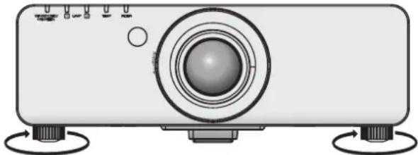
The adjustable feet can be extended by turning it as shown in the figure. It is retracted by turning it in the opposite direction. (Projection angle can be adjusted vertically.)
natural_image
Illustration of a projector with control knobs and a central lens (no text or symbols)
Adjustable range
Front adjustable feet: 30 mm
Attention
- Heated air is blowing out from the air exhaust port while the lamp is on. Do not touch the air exhaust port directly when adjusting the adjustable feet.
Removing/attaching the projection lens
Perform the following steps when removing/attaching the standard zoom lens or the optional lens. Move the lens to the home position before replacing or removing the lens. (→ page 36)
Attention
- Replace the projection lens after turning off the power of the projector.
- Do not touch the lens signal receiver. Dust or dirt may cause defective contact.
- Do not touch the lens surface with your bare hands.
● Before attaching the projection lens, remove the dust sponge attached to the projector and the lens cover attached to the projection lens.
- For the ultra short-focus zoom lens (ET-DLE080), the procedure for removing/attaching the lens is different. For details, refer to the instruction manual supplied with ET-DLE080.
Removing the projection lens
1) Turn the projection lens cover counterclockwise and remove.

2) While pressing the lens release button, turn the projection lens counterclockwise all the way, and remove the projection lens.

(i) Lens release button
Attention
- Store the removed lens where it will be free from vibration and impact.
Attaching the projection lens
1) Remove the projection lens cover, align the guide of the projection lens to the guide groove on the projector, and then insert the projection lens.

2) Turn the projection lens clockwise until it clicks.

natural_image
Technical line drawing of a mechanical component with no visible text or symbols
3) Attach the projection lens cover aligning the marking (groove *1) to the tip of the arrow on the projector (*2), and then turn and secure the projection lens cover until the *1 groove aligns with the *3 ▪ marking.

Attention
● Turn the projection lens counterclockwise to confirm that it does not come out.
Connections
Before connecting to the projector
- Read carefully the instruction manual for the device to be connected.
● Turning off the power switch of the devices before connecting cables.
- If any connection cable is not supplied with the device, or if no optional cable is available for the connection of the device, prepare a necessary system connection cable to suit the device.
- Video signals containing too much jitter may cause the images on the screen to randomly wobble or wafture. In this case, a time base corrector (TBC) must be connected.
● The projector accepts the following signals: VIDEO, S-VIDEO, analog RGB (with TTL sync. Level) and digital signal.
- Some computer models are not compatible with the projector.
- Use a compensator when you connect each of equipment to the projector using long cables. Otherwise the image may not be output properly.
■ terminal pin assignments and signal names
| Outside view Pin No. Signal names |
| (1)(2) | (1) | Ground (luminance signal) |
 | (2) | Ground (color signal) |
| (3) | Luminance signal |
| ... | (4) | Color signal |
terminal pin assignments and signal names
| Outside view Pin No. | Signal names |
(1)(15)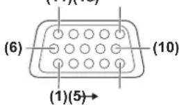 | (1) | R/PR |
| (2) | G/Y |
| (3) | B/PB |
| (12) | DDC data |
| (13) | SYNC/HD |
| (14) | VD |
| (15) | DDC clock |
(4) and (9) are not used.
(5) - (8), (10), and (11) are GND terminals.
■ terminal pin assignments and signal names
Outside view Pin No.  | Signal name | Pin No. Signal names | | |
| (1) | T.M.D.S data 2- | (13) | - |
| (2) | T.M.D.S data 2+ | (14) | +5 V |
| (3) | T.M.D.S data 2/4 shield | (15) | GND |
| (4) | - | (16) | Hot plug detection |
| (5) | - | (17) | T.M.D.S data 0- |
| (6) | DDC clock | (18) | T.M.D.S data 0+ |
| (7) | DDC data | (19) | T.M.D.S data 0/5 shield |
| (8) | - | (20) | - |
| (9) | T.M.D.S data 1- | (21) | - |
| (10) | T.M.D.S data 1+ | (22) | T.M.D.S clock shield |
| (11) | T.M.D.S data 1/3 shield | (23) | T.M.D.S clock+ |
| (12) | - | (24) | T.M.D.S clock- |
Connecting example: AV equipment

Attention
● Always use one of the following when connecting a VCR.
- A VCR with built-in time base corrector (TBC)
– A time base corrector (TBC) between the projector and the VCR
- If nonstandard burst signals are connected, the image may be distorted. In such case, connect the time base corrector (TBC) between the projector.
Note
- The terminal can be used to connect the projector with an HDMI- or DVI-D compliant device. However, with some devices the images may not appear. (▶ page 58)
● To connect an HDMI compatible device, an HDMI-DVI-D conversion cable is required.
- When the DVI-D signal is input, EDID setting may be required depending on the connected device. (→ page 58)
Connecting example: Computers

flowchart
graph TD
    A["Control computer"] --> B["Computer Computer"]
    B --> C["LAN"]
    B --> D["VIDEO IN"]
    B --> E["VIDEO IN"]
    B --> F["RGB 1 IN"]
    B --> G["GPIO"]
    B --> H["RGB 2 IN"]
    B --> I["DVO IN"]
    J["Control computer"] --> K["Computer"]
    K --> L["RAM"]
    L --> M["RAM"]
    M --> N["RAM"]
    N --> O["RAM"]
    O --> P["RAM"]
    P --> Q["RAM"]
    Q --> R["RAM"]
    R --> S["RAM"]
    S --> T["RAM"]
    T --> U["RAM"]
    U --> V["RAM"]
    V --> W["RAM"]
    W --> X["RAM"]
    X --> Y["RAM"]
    Y --> Z["RAM"]
    Z --> AA["RAM"]
    AA --> AB["RAM"]
    AB --> AC["RAM"]
    AC --> AD["RAM"]
    AD --> AE["RAM"]
    AE --> AF["RAM"]
    AF --> AG["RAM"]
    AG --> AH["RAM"]
    AH --> AI["RAM"]
    AI --> AJ["RAM"]
    AJ --> AK["RAM"]
    AK --> AL["RAM"]
    AL --> AM["RAM"]
    AM --> AN["RAM"]
Note
- The terminal is compatible only with single link DVI signals.
- Refer to “List of compatible signals” (→ page 102) for the details of the RGB signal from the computer that the projector supports.
- If you operate the projector using the computer with the resume feature (last memory), it is required to reset the resume feature to operate the projector.
- When the SYNC ON GREEN signal is input, do not input sync signals to the and terminals.
- When the DVI-D signal is input, EDID setting may be required depending on the connected device. (→ page 58)
Caution
When connecting the projector to a computer or an external device, use the power cord supplied with each device and commercially available shielded cables.
Powering ON/OFF
Connecting the power cord
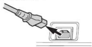
Be sure to insert the supplied power cord securely to its base to prevent it from coming off. Confirm that the switch is at the side, before connecting the power cord.
■Attaching
1) Check the shapes of the AC IN terminal and the power cord connector and insert the plug securely in the correct direction.

natural_image
Illustration of a plug inserted into a socket (no text or symbols)
2) Attach the power cord secure lock along with the guide on the AC IN terminal .

3) Push in the tab of the power cord secure lock until it clicks.

natural_image
Diagram of a cable tab inserted into a connector, showing mechanical assembly (no text or symbols)
4) Connect the power plug to the outlet.
Removing
1) Confirm that the switch is at the side and unplug the power cord from the outlet.
2) Push down the tab of the power cord secure lock.

3) Remove the power cord secure lock upward along with the guide of the AC IN terminal .

4) Remove the plug from the AC IN terminal .
natural_image
Illustration of a plug inserted into a socket (no text or symbols)
Power indicator
The power indicator informs you of the power status. Check the status of the power indicator before operating the projector.
Power indicator
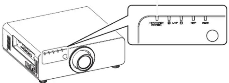
| Indicator status Status | |
| No illumination No | illumination The main power is switched off. |
| Red Lit | | The power is switched off. (Standby mode)● Press the POWER ON < | > button to start the projection.When the lamp indicator/ or temperature indicatoris flashing, you cannot operate the projector.(→ page 87) |
| Green Lit Projecting. | |
| Orange Lit | | The projector is getting ready to be switched off.The power will be switched off momentarily. (Standby mode) |
Note
- When the power indicator < STANDBY (RED)/ON (GREEN)> is lit in orange, the fan is operating to cool the projector.
- Electricity is consumed even in the standby mode (even when the power indicator lit in red).
Powering ON/OFF


Powering up the projector
When using the optional projection lens, attach the projection lens before turning on the power page 29) Remove the lens cover beforehand.
1) Connect the power plug to the outlet.
(AC 120 V 50 Hz/60 Hz)
2) Press the side of the switch to turn on the power.
- The power indicator will light in red, and the projector will enter the standby mode.
3) Press the POWER ON < > button.
● The power indicator will light in green and soon the image is projected on the screen.
Note
- If the projector is turned on at about 0°C (32°F), a warm-up period of approximately five minutes may be necessary to start projection.
The temperature indicator lights up during the warm-up period. When the warm-up is completed, the temperature indicator turns off and the projection starts. Refer to "Managing the indicated problems" (→ page 87) for the indicator status.
- If the temperature of the operating environment is low and warm-up takes more than five minutes, the projector will judge that a problem has occurred and the power is automatically set to stand-by. If this happens, increase the temperature around the projector so that it is 0^ (32°F) or higher and turn off the main power, and then turn on the power again.
- When turning on the power, if [ECO] is selected in the [PROJECTOR SETUP] menu [STANDBY MODE] (→ page 63), projection will start approximately ten seconds later than when [NORMAL] is selected.
- If the direct power off function was used to set the switch to during projection, the next time the switch is set to with the power plug connected to the outlet, The power indicator will soon light green and an image will be projected.
Making adjustment and selection
It is recommended that the images are projected continuously for at least 30 minutes before the focus is adjusted.
4) Press the button to adjust the focus of the image roughly.
(→ page 36)
5) Set the projection method using [PROJECTION METHOD] (→ page 61) and [COOLING CONDITION] (→ page 62).
- Refer to "Navigating through the menu" (→ page 41) regarding the operation of the menu screen.
6) Press the Input Selection (, , ,


Powering off the projector
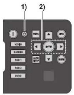
1) Press the STANDBY <∅ button.
2) Press the ◀▶ buttons to select [OK], and press the button. (Or press the STANDBY <⏻> button again.)
- Projection of the image will stop, and the Power indicator on the projector lights in orange.
(The fan keeps running.)
3) Wait until the power indicator of the projector turns red (until the fan stops).
4) Press the side of the switch to turn off the power.
Note
- Do not turn on the power immediately after turning it off.
In the cooling state of the luminous lamp after the power is turned off, the lamp may not light up even if the power is turned on. To light up the lamp, turn on the power again after the luminous lamp goes into standby status. Turning on the power while the lamp is still hot may shorten the lamp life.
- The projector consumes approximately 8 W power when the power is turned off by the remote control with the main power of the projector turned on.
(When [STANDBY MODE] is set to [NORMAL])
If [STANDBY MODE] (→ page 63) is set to [ECO], the power consumption in the standby mode can be reduced.
Direct power off function
Even if you turn the switch [OFF] during projection or just after the lamp turns off, the cooling fan will continue to rotate using internally stored power. In cases where the switch is not easily accessible, such as during ceiling mount, you can safely turn off the power by using the power breaker switch. This function also works if a power outage occurs or if the power cable is accidentally disconnected from the outlet right after turning off the power.
Note
- If projection was stopped by turning off the power breaker switch and you turn on the power breaker again, the power indicator will light in green and projection will start again.
- When the lamp has been cooled by the direct power off function, it sometimes takes longer than usual for the lamp to light up again.
- Confirm that the fan has stopped before packing the projector to transport or store.
Projecting
Check the connections of the external devices, attachment of the projection lens ( page 29), and connection of the power cord ( page 32), and turn on the power ( page 34) to start the projection. Select the input signal and adjust the image.
Select an input signal.
Press the Input Selection (, , ,
● Image for the selected input signal is projected.
Attention
● Images may not be projected properly depending on the connected device and DVD, video tape, etc. to be played.
Select a system format matching the input signal from the [PICTURE] menu → [SYSTEM SELECTOR] (→ page 47).
- Confirm the aspect ratio of the screen to project and the image, and switch to an optimum aspect ratio from the [POSITION] menu → [ASPECT] (→ page 48).
Adjusting the focus, zoom, and shift
If the projected image or the position is not correct when the positioning of the projector and the screen is correctly installed, adjust the focus, zoom, and shift.
At the projector
1) Press the button on the control panel.
- Pressing the button changes the setup screen in the order of [FOCUS] [ZOOM], and [SHIFT].
2) Select each item and press ▲▼◀▶ to adjust it.
■Using the remote control
1) Press the Lens (, , and ) buttons on the remote control.
- button: Adjusts focus.
- button: Adjusts zoom.
- button: Adjusts shift.
2) Select each item and press ▲▼◀▶ to adjust it.
Note
- Zoom adjust menu will be displayed even when the lens without the zoom function is used, but it will not operate.
- The adjustment can be performed faster by pressing and holding ▲▼◀▶ for at least three seconds.
- It is recommended that the images are projected continuously for at least 30 minutes before the focus is adjusted.
- [FOCUS] is shown in yellow so that the displayed menu item can be recognized by color, even when the projector is not focused and displayed characters are unreadable. (Factory default) Displaying color of [FOCUS] is different depending on the setting in the [OSD DESIGN] menu (→ page 59).
Moving the lens to the home position
1) Press the button on the control panel or the button on the remote control for at least three seconds.
2) While the [HOME POSITION] menu is displayed (for approximately five seconds), press the button.
LENS
HOME POSITION
[ENTER] EXECUTE
[MENU] CANCEL.
● [PROGRESS] is displayed in the menu screen, and the lens returns to the home position.
Attention
● The home position of the lens is the lens position when the lens is being replaced or when the projector is being stored, and it is not the optical center of the screen.
Adjustment range by the lens position shift (optical shift)
Perform the lens position shift within the adjustment range.
The focus may change when the lens position is shifted out of the adjustment range. This is because the movement of the lens is restricted to protect the optical parts. Projection position can be adjusted with the optical axis shift based on the standard projection position in the range shown in the following figures.
| Lens type | Zoom lens |
| Standard zoom lens, ET-DLE150, ET-DLE250, ET-DLE350, ET-DLE450 | ET-DLE080 |
| PT-DW730U | 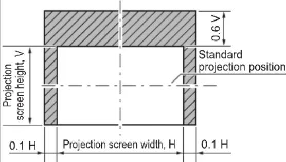 |  |
| PT-DX800U |  |  |
* The above are the figures when the projector is placed on the floor.
Note
- When the fixed-focus lens (ET-DLE055) is attached, shift adjustment cannot be performed.
Basic operations using the remote control

Using the SHUTTER function
If the projector is not used for a certain period of time during the meeting intermission, for example, it is possible to turn off the image temporarily.

1) Press the button on the remote control or the control panel.
● The image disappears.
2) Press the button again.
- The image resumes.
Using the on-screen display function
Turn off the on-screen display function (no display) when you do not wish the viewers to see the on-screen display, such as the menu or the input terminal name.

1) Press the button on the remote control.
● The on-screen display is turned off.
2) Press the button again.
● The on-screen display is turned on.
Note
- If the
- The CLOCK PHASE may shift even if it has completed without any incident. In such cases, adjust with the [POSITION] menu [CLOCK PHASE] (→ page 50).
- If an image with blurred edges or a dark image is input, [INCOMPLETE] may appear or adjustment may not be performed properly even if [COMPLETE] appears. In this case, adjust the settings in the [ADVANCED MENU] menu→ [INPUT RESOLUTION] (→ page 52), [POSITION]→ [CLOCK PHASE] (→ page 50), [SHIFT] (→ page 48).
- Adjust specific signals according to the [DISPLAY OPTION] menu [AUTO SETUP] (→ page 57).
● Automatic adjustment may not work depending on the model of the computer.
● Automatic adjustment may not work for a synchronization signal of C-SYNC or SYNC ON GREEN.
- Images may be disrupted for a few seconds during automatic adjustment, but it is not a malfunction.
- Adjustment is required for each input signal.
- Automatic adjustment can be canceled by pressing the
- Even for an RGB signal for which automatic setup is possible, if automatic setup is performed while moving images are being input, [INCOMPLETE] may appear, or adjustment may not be performed properly even if [COMPLETE] appears.
[DISABLE], [SUB MEMORY], [SYSTEM SELECTOR], [SYSTEM DAYLIGHT VIEW], [FREEZE], or [SIDE BY SIDE] operations can be assigned to the button on the remote control so that it can be used as an easy shortcut button.
FUNCTION ○ button
Note
● [SIDE BY SIDE] can be set up only with PT-DW730U.
- Assignment of the button is performed from the [PROJECTOR SETUP] menu → [FUNCTION BUTTON] (→ page 65).
Displaying the internal test pattern
The projector has nine types of internal test patterns to check the condition of the set. To display test patterns, perform the following steps.
TEST PATTERN button
1) Press the button on the remote control.
2) Press ◀▶ to select the test pattern.
Note
- Setting is also available from the [TEST PATTERN] menu (→ page 67).
- Settings of position, size, and other factors will not be reflected in test patterns. Be sure to display an actual input signal before performing these adjustments.
Basic operations using the remote control
Changing the picture aspect ratio
You can toggle through aspect ratios to select the one that is appropriate for the input signal.

- The setting will change as follows each time the button is pressed.

flowchart
graph TD
    A["[VID AUTO"]^1] --> B["[DEFAULT"]]
    B --> C["[HV FIT"] [THROUGH]]
    C --> D["[V FIT"] [16:9]]
    D --> E["[H FIT"]]
    E --> F["[4:3"]]
    B --> G["[S1 AUTO"]^2]
    G --> H["[VID AUTO(PRI.)"]^2]
    H --> I["↓"]
    I --> J["↓"]
    J --> K["↓"]
    K --> L["↓"]
    L --> M["[4:3"]]
*1: VIDEO, S-VIDEO (NTSC) only
*2: S-VIDEO (NTSC) only
Note
- Some aspect ratios may not be available depending on the input signal.
Refer to “[ASPECT]” (→ page 48) for details.
The on-screen menu (Menu screen) is used to perform various settings and adjustments of the projector.
■Operating procedure

● The [MAIN MENU] screen is displayed.

2) Press ▲to select the main menu item.
● The selected item is highlighted in yellow.

- The sub-menu items of the selected main menu are displayed.

- For some items, press ◀▶ to display an individual adjustment screen with a bar scale as shown in the following diagram.

Note
- Press the
- Some items may not be adjusted or used for certain signal formats input to the projector. The menu items that cannot be adjusted or used are shown in gray characters, and they cannot be selected.
- Some items can be adjusted even if signals are not input.
- Individual adjustment screen is cleared automatically if no operation is performed for approximately five seconds. (Excluding some functions)
- Refer to "MAIN MENU" (→ page 42) or "SUB MENU" (→ pages 42 to 43) regarding the menu items.
- The selected item is displayed with the yellow cursor by default. The cursor color depends on the setting in [OSD DESIGN] (→ page 59).
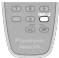
■ Resetting to the factory default
If the button on the remote control is pressed, the values set in the menu will be restored to the factory default settings.
DEFAULT

Press the button on the remote control.

Note
- You cannot reset all the settings to the factory default at a time.
- To reset all the settings adjusted in the sub-menu item to the factory default at a time, perform initialization from the [PROJECTOR SETUP] menu [INITIALIZE] (→ page 66).
- Some menu items cannot be reset by pressing the button. Adjust each item manually.
- The triangular mark under the bar scale in the individual adjustment screen indicates the factory default setting.
The position of the triangular mark varies by the selected input signals.

MAIN MENU
There are following ten items in the main menu. When a main menu item is selected, the screen changes to a sub-menu selection screen.
| Main menu item Page | |
 | [PICTURE] 42 | |
 | [POSITION] 42 | |
 | [ADVANCED MENU] 42 | |
 | [DISPLAY LANGUAGE] 43 | |
 | [DISPLAY OPTION] 43 | |
 | [PROJECTOR SETUP] 43 | |
 | [TEST PATTERN] 43 | |
 | [SIGNAL LIST] 43 | |
 | [SECURITY] 43 | |
 | [NETWORK] 43 | |
The sub-menu screen of the selected main menu is displayed, and you can set and adjust the various items in the sub-menu.
[PICTURE]
| Sub-menu item | Factory default | Page |
| [PICTURE MODE] | [STANDARD]^1 | 44 |
| [CONTRAST] [0] 44 | | |
| [BRIGHTNESS] | [0] | 44 |
| [COLOR] | [0] | 45 |
| [TINT] | [0] | 45 |
| [COLOR TEMPERATURE] | [DEFAULT] | 45 |
| [WHITE GAIN] | [10] | 46 |
| [SYSTEM DAYLIGHT VIEW] | [OFF]^1 | 46 |
| [SHARPNESS] | [6] | 46 |
| [NOISE REDUCTION] | [1] | 46 |
| [AI] | [ON] | 47 |
| [SYSTEM SELECTOR] | [YP_BP_R]^1 | 47 |
*1: Depends on the signal input.
Note
- The factory default settings may vary depending on the picture mode.
[POSITION]
| Sub-menu item | Factory default | Page |
| [SHIFT] | — | 48 |
| [ASPECT] | [DEFAULT]^*1 | 48 |
| [ZOOM] | — | 49 |
| [CLOCK PHASE] | [16] | 50 |
| [KEYSTONE] | — | 50 |
*1: Depends on the signal input.
| Sub-menu item | Factory default | Page |
| [ DIGITAL CINEMA REALITY] | [AUTO]*1 | 51 |
| [BLANKING] | — | 51 |
| [INPUT RESOLUTION] | — | 52 |
| [CLAMP POSITION] | [0] | 52 |
| [EDGE BLENDING] | [OFF] | 52 |
| [RASTER POSITION] — | 53 | |
*1: Depends on the signal input.
■[DISPLAY LANGUAGE]
Details ( page 54)
[DISPLAY OPTION]
| Sub-menu item | Factory default | Page |
| [COLOR MATCHING] [OFF] 55 | | |
| [COLOR CORRECTION] [OFF] 56 | | |
| [CONTRAST MODE] [DEFAULT] 56 | | |
| [SCREEN SETTING] — 57 | | |
| [AUTO SIGNAL] [OFF] 57 | | |
| [AUTO SETUP] — 57 | | |
| [DVI-D IN] — 58 | | |
| [ON-SCREEN DISPLAY] — | 58 | |
| [BACK COLOR] | [BLUE] | 59 |
| [STARTUP LOGO] | [DEFAULT LOGO] | 60 |
| [FREEZE] | — 60 | |
| [SIDE BY SIDE] ^1 | — 60 | |
*1: Only for PT-DW730U.
■[PROJECTOR SETUP]
| Sub-menu item | Factory default | Page |
| [PROJECTOR ID] | [ALL] | 61 |
| [PROJECTION METHOD] | [FRONT/FLOOR] | 61 |
| [HIGH ALTITUDE MODE] | [OFF] | 61 |
| [COOLING CONDITION] | [FLOOR SETTING] | 62 |
| [LAMP SELECT] | [DUAL] | 62 |
| [LAMP RELAY] | [OFF] | 63 |
| [LAMP POWER] | [HIGH] | 63 |
| [STANDBY MODE] | [NORMAL] | 63 |
| [RS-232C] — 63 | | |
| [REMOTE2 MODE] | [DEFAULT] | 64 |
| [STATUS] | — | 64 |
| [NO SIGNAL SHUT-OFF] | [DISABLE] | 65 |
| [FUNCTION BUTTON] | — | 65 |
| [DATE AND TIME] — | 65 | |
| [SAVE ALL USER DATA] | — | 65 |
| [LOAD ALL USER DATA] | — | 66 |
| [INITIALIZE] | — | 66 |
| [SERVICE PASSWORD] | — | 66 |
[TEST PATTERN]
Details (→ page 67)
[SIGNAL LIS]
Details ( page 68)
[SECURITY]
| Sub-menu item | Factory default | Page |
| [SECURITY PASSWORD] | [OFF] 70 | |
| [SECURITY PASSWORD CHANGE] | — 70 | |
| [DISPLAY SETTING] | [OFF] 70 | |
| [TEXT CHANGE] | — 71 | |
| [MENU LOCK] | [OFF] 71 | |
| [MENU LOCK PASSWORD] | — 71 | |
| [CONTROL DEVICE SETUP] | — 71 | |
[NETWORK]
| Sub-menu item | Factory default | Page |
| [NETWORK SETUP] | — 73 | |
| [NETWORK CONTROL] | — 73 | |
| [NETWORK STATUS] | — 73 | |
Note
- Some items may not be adjusted or used for certain signal formats to be input to the projector.
The menu items that cannot be adjusted or used are shown in gray characters, and they cannot be selected.
- Sub-menu items and factory default settings differ depending on the selected input terminal.
Select [PICTURE] from the main menu, and select the item from the sub-menu.
Refer to "Navigating through the menu"
(→ page 41) regarding the operation of the menu screen.
● After selecting the item, press ▲▼◀▶ to set.


[PICTURE MODE]
You can switch to the desired picture mode suitable for the image source and the environment in which the projector is used.
1) Press ▲▼ to select [PICTURE MODE].
2) Press ◀▶ or press the button.
● The [PICTURE MODE] individual adjustment screen is displayed.
3) Press ◀▶ to switch [PICTURE MODE].
● The setting will change as follows each time you press the button.
[STANDARD] ↔ [CINEMA] [NATURAL]
![PANASONIC PT-DW730U - [PICTURE MODE] - 1](/content/2026/06/1201863/images/5c686b4a7a0eb98b5b0e656d4162a25ee2c0d3410c45d2bfa00779176e297149.jpg)
flowchart
graph TD
    A["[STANDARD"]] <--> B["[CINEMA"] [NATURAL]]
    B --> C["[GRAPHIC"] [DYNAMIC]]
    C --> D[" "]
    D --> C
| [STANDARD] | The picture becomes suitable for moving images in general. |
| [CINEMA] | The picture becomes suitable for movie sources. |
| [NATURAL] | The picture complies with sRGB. |
| [DYNAMIC] | The light output is maximized for use in bright areas. |
| [GRAPHIC] | The picture becomes suitable for input from to the personal computer. |
Note
- The factory default picture mode is [GRAPHIC] for the still image signal input mode, and [STANDARD] for the movie signal input mode.
[CONTRAST]
You can adjust the contrast of the colors.
1) Press ▲▼ to select [CONTRAST].
2) Press ◀▶ or the button.
● The [CONTRAST] individual adjustment screen is displayed.
3) Press ◀▶ to adjust the level.
| Operation Adjustment | Adjustment range |
| Press ▶ . | Brightens the screen and makes the color of image deeper. | Maximum value +31 |
| Press ◀ . | Darkens the screen and makes the color of image lighter. | Minimum value -31 |
Attention
- Adjust [BRIGHTNESS] first when you need to adjust the black level.
[BRIGHTNESS]
You can adjust the dark (black) part of the projected image.
1) Press ▲▼ to select [BRIGHTNESS].
2) Press ◀▶ or the button.
● The [BRIGHTNESS] individual adjustment screen is displayed.
3) Press ◀▶ to adjust the level.
| Operation Adjustment | Adjustment range |
| Press ▶ . | Increases the brightness of the dark (black) parts of the screen. | Maximum value +31 |
| Press ◀ . | Reduces the brightness of the dark (black) parts of the screen. | Minimum value -31 |
[COLOR]
You can adjust the color saturation of the projected image.
1) Press ▲▼ to select [COLOR].
2) Press ◀▶ or the button.
- The [COLOR] individual adjustment screen is displayed.
3) Press ◀▶ to adjust the level.
| Operation Adjustment | Adjustment range |
| Press ▶ . Deepens colors. | Maximum value +31 |
| Press ◀ . Weakens colors. | Minimum value -31 |
[TINT]
You can adjust the skin tone in the projected image.
1) Press ▲▼ to select [TINT].
2) Press ◀▶ or the button.
● The [TINT] individual adjustment screen is displayed.
3) Press ◀▶ to adjust the level.
| Operation Adjustment | Adjustment range |
| Press ▶ . | Adjusts skin tone toward greenish color. | Maximum value +31 |
| Press ◀ . | Adjusts skin tone toward reddish purple. | Minimum value -31 |
[COLOR TEMPERATURE]
You can switch the color temperature if the white areas of the projected image are bluish or reddish.
1) Press ▲▼ to select [COLOR TEMPERATURE].
2) Press ◀▶ or the button.
● The [COLOR TEMPERATURE] individual adjustment screen is displayed.
3) Press ◀▶ to switch [COLOR TEMPERATURE].
- The setting will change as follows each time you press the button.
![PANASONIC PT-DW730U - [COLOR TEMPERATURE] - 1](/content/2026/06/1201863/images/1e063aec6e3bade198edeaccf5e60292ed850a0b01ec758bb8189c1b3566a5f3.jpg)
flowchart
graph TD
    A["DEFAULT"] --> B["USER"]
    C["HIGH"] --> D["MIDDLE"]
    B <--> C
- When any setting other than [OFF] has been selected for [COLOR MATCHING] (→ page 55) the [COLOR TEMPERATURE] setting is fixed to [USER].
■To further adjust toward the desired white balance
4) Select [USER] in Step 3).
5) Press the button.
● The [WHITE BALANCE] screen is displayed.
6) Press ▲▼ to select [WHITE BALANCE HIGH] or [WHITE BALANCE LOW].
7) Press the button.
● The [WHITE BALANCE HIGH] screen or the [WHITE BALANCE LOW] screen is displayed.
8) Press ▲▼ to select [RED], [GREEN], or [BLUE].
9) Press ◀▶ to adjust the level.
| Item Operation | Adjustment | Adjustment range |
| [RED] | Press ▶ . | Deepens red. | Maximum valueHIGH: 255LOW: 63 |
| Press ◀ . | Weakens red. |
| [GREEN] | Press ▶ . | Deepens green. | Minimum valueHIGH: 0LOW: 0 |
| Press ◀ . | Weakens green. |
| [BLUE] | Press ▶ . | Deepens blue. | DefaultHIGH: 255LOW: 32 |
| Press ◀ . | Weakens blue. |
Note
- Adjust [COLOR TEMPERATURE] correctly. All colors will not be displayed properly unless adequate adjustment is made. If the adjustment does not look suitable, you can press the button on the remote control to return the setting for the selected item only to the factory default setting.
- Internal test pattern (→ page 67) will not reflect the settings of the [COLOR TEMPERATURE]. Be sure to perform the setting of the [COLOR TEMPERATURE] with the input signal projected.
[WHITE GAIN]
You can adjust the brightness of the white part of the projected image.
1) Press ▲▼ to select [WHITE GAIN].
2) Press ◀▶ or the button.
● The [WHITE GAIN] individual adjustment screen is displayed.
3) Press ◀▶ to adjust the level.
| Operation Adjustment | Adjustment range |
| Press ▶ . | Increases the brightness of white. | Maximum value +10 |
| Press ◀ . | Makes image natural. | Minimum value 0 |
[SYSTEM DAYLIGHT VIEW]
You can correct the image to the optimal vividness even if it is projected under a bright light.
1) Press ▲▼ to select [SYSTEM DAYLIGHT VIEW].
2) Press ◀▶ or the button.
● The [SYSTEM DAYLIGHT VIEW] individual adjustment screen is displayed.
3) Press ◀▶ to switch [SYSTEM DAYLIGHT VIEW].
- The setting will change as follows each time you press the button.
![PANASONIC PT-DW730U - [SYSTEM DAYLIGHT VIEW] - 1](/content/2026/06/1201863/images/da4d504079f2462f9b41a4865671cb6b287070e83928d37ce1c988fc869be763.jpg)
flowchart
graph TD
    A["[OFF"] (No correction)] <--> B["[1"] (Low)]
    B <--> C["[3"] (High) [2] (Medium)]
    C <--> A
[SHARPNESS]
You can adjust the sharpness of the projected image.
1) Press ▲▼ to select [SHARPNESS].
2) Press ◀▶ or the button.
● The [SHARPNESS] individual adjustment screen is displayed.
3) Press ◀▶ to adjust the level.
| Operation Adjustment | Adjustment range |
| Press ▶ . | Contours become sharper. | 0 - 15 |
| Press ◀ . | Contours become softer. |
Note
- When the adjustment value is [15], press ▶ to set to [0]. Also, when the adjustment value is [0], press ◀ to set to [15].
[NOISE REDUCTION]
You can reduce noises when the input image is degraded and noise is occurring in the image signal.
1) Press ▲▼ to select [NOISE REDUCTION].
2) Press ◀▶ or the button.
● The [NOISE REDUCTION] individual adjustment screen is displayed.
3) Press ◀▶ to switch [NOISE REDUCTION].
● The setting will change as follows each time you press the button.
![PANASONIC PT-DW730U - [NOISE REDUCTION] - 1](/content/2026/06/1201863/images/14cc3ec9ffde8ba082259b52d34889db5b32dc90bfc147002757b8ba2b06776a.jpg)
flowchart
graph TD
    A["[1"] (Low) [2] (Medium)] <--> B["[OFF"] (No correction)]
    B <--> C["[3"] (High)]
Attention
- When this is set for an input signal with less noise, the image may look different from what it originally was. In such case, set it to [OFF].
[Al]
You can project the optimal image with contrast by controlling the gradation in accordance with the image.
1) Press ▲▼ to select [Al].
2) Press ◀▶ or the button.
● The [AI] individual adjustment screen is displayed.
3) Press ◀▶ to switch [Al].
● The setting will change as follows each time you press the button.
![PANASONIC PT-DW730U - [Al] - 1](/content/2026/06/1201863/images/b29306b78b3f7d6cda0b01de770b224fe491699e9072d849de06079172c718a9.jpg)
[ON] AI correction is enabled.
[OFF] AI correction is disabled.
[SYSTEM SELECTOR]
The projector will automatically detect the input signal, but you can set the system method manually when an unstable signal is input. Set the system method matching the input signal.
1) Press ▲▼ to select [SYSTEM SELECTOR].
2) Press the button.
3) Press ▲▼ to select the system method.
4) Press the button.
■When entering signals to the
- Select [AUTO], [NTSC], [NTSC4.43], [PAL], [PAL-M], [PAL-N], [SECAM], or [PAL60].
Attention
- Set it to [AUTO] normally.
- Switch the setting to the signal method for the TV used. The NTSC signal method is used in Japan.
Note
- Setting [AUTO] will automatically select [NTSC], [NTSC4.43], [PAL], [PAL-M], [PAL-N], [SECAM], or [PAL60].
■When entering signals to the / terminal
- Only during 480i, 576i, or 576p signal input Select [RGB] or [YCBCR] .
- Only during VGA60 or 480p signal input Select [VGA60], [480p], or [480pRGB].
- During movie signal input other than previously listed
Select [RGB] or [YPBPR] .
Note
- Refer to "List of compatible signals" (→ page 102) for compatible signals.
Select [POSITION] from the main menu, and select the item from the sub-menu.
Refer to "Navigating through the menu"
(→ page 41) regarding the operation of the menu screen.
● After selecting the item, press ▲▼◀▶ to set.


[SHIFT]
You can move the image position vertically or horizontally if the image position projected on the screen is shifted even when the relative position of the projector and the screen is installed correctly.
1) Press ▲▼ to select [SHIFT].
2) Press the button.
● The [SHIFT] screen is displayed.
3) Press ▲▼◀▶ to adjust the position.
■For vertical (up and down) adjustment
| Operation Adjustment |
| Press ▲ . | The picture position moves up. | 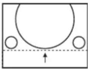 |
| Press ▼ . | The picture position moves down. | 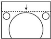 |
■For horizontal (right and left) adjustment
| Operation Adjustment |
| Press ▶ . | The picture position moves to the right. |  |
| Press ◀ . | The picture position moves to the left. | 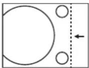 |
[ASPECT]
You can switch the aspect ratio of the image. The aspect ratio is switched within the screen range selected in [SCREEN SETTING]. Set [SCREEN SETTING] first. (→ page 57)
1) Press ▲▼ to select [ASPECT].
2) Press ◀▶ or the button.
- The [ASPECT] individual adjustment screen is displayed.
3) Press ◀▶ to switch [ASPECT].
● The setting will change as follows each time you press the button.
![PANASONIC PT-DW730U - [ASPECT] - 1](/content/2026/06/1201863/images/a1201443cbe2673ae8efd4921924cf52a704e37e7adfb662a27a9d46a5448b0e.jpg)
flowchart
graph TD
    A["[VID AUTO"]^1\n["DEFAULT"]] <--> B["[S1 AUTO"]^2]
    B <--> C["[VID AUTO(PRI.)"]]
    C <--> D["[THROUGH"]]
    D <--> E["[16:9"]]
    E <--> F["[V FIT"] [H FIT] [4:3]]
    F <--> G["[HV FIT"]]
    G <--> A
*1: Only during VIDEO or S-VIDEO (NTSC) input.
*2: Only during S-VIDEO (NTSC) input.
[DEFAULT]
Pictures are displayed without changing the aspect ratio of the input signals.
[VID AUTO]
The projector identifies the video ID (VID) embedded in the picture signals and displays the picture by automatically switching the screen sizes between 4:3 and 16:9. This function is effective for NTSC signals.
[S1 AUTO]
The projector identifies the S1 signal and displays the picture by automatically switching the screen sizes between 4:3 and 16:9. This function is effective for S-VIDEO NTSC signals.
[VID AUTO(PRI.)]
The projector identifies the above mentioned VID or S1 signals and displays the picture by automatically choosing the screen sizes of 4:3 or 16:9 according to the VID if it is detected or S1 signals if a VID is not detected. This function is effective for S-Video NTSC signals.
[THROUGH]
Pictures are displayed without changing the resolution of the input signals.
[16:9]
When standard signals ^1 are input, the pictures are displayed with the aspect ratio converted to 16:9. When wide-screen signals ^2 are input, the pictures are displayed without changing the aspect ratio.
[4 : 3]
When standard signals ^1 are input, the pictures are displayed without changing the aspect ratio. When wide-screen signals ^2 are input and [4:3] is selected with [SCREEN FORMAT], the aspect ratio is changed to 4:3. If [4:3] is not selected with [SCREEN FORMAT], the pictures are reduced so that they will be in the 4:3 screen without changing the input aspect ratio.
[H FIT]
The display will use the full width of the screen range selected with [SCREEN FORMAT]. When signals have a vertical aspect ratio that is larger than the screen aspect selected with [SCREEN FORMAT], the pictures will be displayed with their top or bottom areas cut off.
[V FIT]
The display will use the full height of the screen range selected with [SCREEN FORMAT].
■[HV FIT]
The pictures are displayed in the full screen range selected with [SCREEN FORMAT]. If the aspect ratios of the input signals and screen range differ, conversion to the screen aspect set with [SCREEN FORMAT] is performed and then the pictures are displayed.
*1: Standard signals are input signals with an aspect ratio of 4:3 or 5:4.
*2: Wide-screen signals are input signals with an aspect ratio of 16:10, 16:9, 15:9 or 15:10.
Note
- Some size modes are not available for certain types of input signals. For NTSC signals, [DEFAULT] cannot be selected.
- If an aspect ratio which is different from the aspect ratio for the input signals is selected, the pictures will appear differently from the originals. Be careful of this when selecting the aspect ratio.
- If using this projector in places such as cafes or hotels to display programs for a commercial purpose or for public presentation, note that adjusting the aspect ratio or using the zoom function to change the screen pictures may be an infringement of the rights of the original copyright owner for that program under copyright protection laws. Take care when using a function of the projector such as the aspect ratio adjustment, zoom function, etc.
- If conventional (normal) 4:3 pictures which are not wide-screen pictures are displayed on a wide screen, the edges of the pictures may not be visible or they may become distorted. Such pictures should be viewed as with an aspect ratio of 4:3 in the original format intended by the creator of the pictures.
[ZOOM]
You can adjust the size of the projected image.
1) Press ▲▼ to select [ZOOM].
2) Press the button.
● The [ZOOM] screen is displayed.
3) Press ▲▼ to select [VERTICAL] or [HORIZONTAL], then press ◀▶ to adjust it.
■When [ASPECT] is set to [DEFAULT]
1) Press ▲▼ to select [MODE].
2) Press ◀▶ to switch [MODE].
| [INTERNAL] | Enlarge the size within the aspect range set in [SCREEN FORMAT]. |
| [FULL] | Enlarges the size of the pictures using the whole of the display area selected with [SCREEN FORMAT]. |
Note
- When [ASPECT] is set to [THROUGH], [ZOOM] is not displayed.
- When anything but [DEFAULT] is selected for [ASPECT], [MODE] is not displayed.
[CLOCK PHASE]
You can adjust to achieve an optimal image when there is a flickering image or smeared outlines.
1) Press ▲▼ to select [CLOCK PHASE].
2) Press ◀▶ or the button.
● The [CLOCK PHASE] individual adjustment screen is displayed.
3) Press ◀▶ to adjust the level.
- Adjustment value will change between [0] and [31]. Adjust so that the amount of interference is at a minimum.
Note
- Optimal value may not be achieved if the output from the input computer is unstable.
- Optimal value may not be achieved when there is a shift in the total dot numbers.
- [CLOCK PHASE] can only be adjusted when a signal is input in the terminal or the terminal.
- To project a signal with dot clock frequency with 150 MHz or higher, noise may not disappear even if [CLOCK PHASE] is adjusted.
- [CLOCK PHASE] cannot be adjusted when a digital signal is input.
- If you press ▶ while the adjustment value is [31], the value turns to [0]. If you press ◀ while the adjustment value is [0], the value turns to [31].
[KEYSTONE]
You can correct the trapezoidal distortion that occurs when the projector is installed tilted or when the screen is tilted.
1) Press ▲▼ to select [KEYSTONE].
2) Press the button.
3) Select the item to adjust.
4) Press ◀▶ to adjust the level.
[KEYSTONE]
![PANASONIC PT-DW730U - [KEYSTONE] - 1](/content/2026/06/1201863/images/ee65207056dd2beb3a54495b3f7034e0916a7ca99c0d8814ec5a5008ebe6937d.jpg)
natural_image
Two geometric diagrams showing a grid-patterned surface with dashed boundaries (no text or symbols)
[SUB KEYSTONE]
![PANASONIC PT-DW730U - [KEYSTONE] - 2](/content/2026/06/1201863/images/2337dcd35f0d62818a9c63cc683acb3a89224613c620a5baac6b6938a3c5ab36.jpg)
natural_image
Two grid diagrams with arrows indicating direction, no text or symbols present
[LINEARITY]
![PANASONIC PT-DW730U - [KEYSTONE] - 3](/content/2026/06/1201863/images/ad9f3804e11b2be18b26c457d428dc5d131aa02616ca63c8b53ddefdc98f60c8.jpg)
natural_image
Two 3D grid diagrams with arrows indicating direction, no text or symbols present
Note
- The menu or logo may run off the screen when various adjustments are performed with [KEYSTONE].
- Various adjustments with [KEYSTONE] are possible to correct up to ± 40^ for the tilt in vertical direction. However, the picture quality will degrade and it will get harder to focus with more correction. Install the projector so the correction will be as small as possible. (Correction can be made up to ± 30^ when the fixed-focus lens (ET-DLE055) or the ultra short-focus zoom lens (ET-DLE080) is used.)
- Image size will also change when various adjustments are performed with [KEYSTONE].
- Trapezoidal distortion may occur depending on the lens shift position.
- Aspect ratio of the image size may shift depending on the correction or lens zoom value.
Select [ADVANCED MENU] from the main menu, and select the item from the sub-menu. Refer to "Navigating through the menu"
(→ page 41) regarding the operation of the menu screen.
● After selecting the item, press ▲▼◀▶ to set.

[DIGITAL CINEMA REALITY]
You can increase the vertical resolution and enhance the picture quality by performing the cinema processing when the PAL (or the SECAM) 576i signal, the NTSC 480i, 1080/50i, and 1080/60i signals are input.
1) Press ▲▼ to select [DIGITAL CINEMA REALITY].
2) Press ◀▶ to switch [DIGITAL CINEMA REALITY].
● The setting will change as follows each time you press the button.
![PANASONIC PT-DW730U - [DIGITAL CINEMA REALITY] - 1](/content/2026/06/1201863/images/847ffb45ee082afb551a846089ca413b662e12971c0e57b21cbc34fa82457ff1.jpg)
flowchart
graph TD
    A["AUTO"] --> B["OFF"]
    B --> C["25p FIXED"]
    C --> D["when a 576i or 1080/50i signal is input"]
    C --> E["30p FIXED"]
    E --> F["when a 480i or 1080/60i signal is input"]
| [AUTO] | Performs automatic detection and cinema processing. (Factory default) |
| [OFF] Unforced cinema processing. |
| [25p FIXED] | Forced cinema processing (2:2 pulldown) is performed when a 576i or 1080/50i signal is input. |
| [30p FIXED] | Forced cinema processing (2:2 pulldown) is performed when a 480i or 1080/60i signal is input. |
Note
- In [DIGITAL CINEMA REALITY] mode, the picture quality will degrade when a signal other than the 2:2 pulldown is set as [25p FIXED] or [30p FIXED]. (Vertical resolution will degrade.)
[BLANKING]
The blanking width is adjusted when there are noise at the edge of the screen or the image is slightly running out from the screen when an image from the VCR or other devices are projected.
1) Press ▲▼ to select [BLANKING].
2) Press the button.
- The [BLANKING] adjustment screen is displayed.
3) Press ▲▼ to select the adjustment item.
4) Press ◀▶ to adjust the blanking.
● Changes within the following range.
For PT-DW730U
Left to right: 0 - 639
Top to bottom: 0 - 399.
For PT-DX800U
Left to right: 0 - 511
Top to bottom: 0 - 383.
When correcting the upper blanking of the screen (top)
Press ◀ to move the blanking zone upward.
Press ▶ to move the blanking zone downward.

When correcting the lower blanking of the screen (bottom)
Press ▶ to move the blanking zone upward.
Press ◀ to move the blanking zone downward.

When correcting the left hand blanking of the screen (left)
Press ▶ to move the blanking zone to the right.
Press ◀ to move the blanking zone to the left.

When correcting the right hand blanking of the screen (right
Press ◀ to move the blanking zone to the right.
Press ▶ to move the blanking zone to the left.

You can adjust to achieve an optimal image when there is a flickering image or smeared outlines.
1) Press ▲▼ to select [INPUT RESOLUTION].
2) Press the button.
- The [INPUT RESOLUTION] screen is displayed.
3) Press ▲▼ to select [TOTAL DOTS], [DISPLAY DOTS], [TOTAL LINES], or [DISPLAY LINES], and press ◀▶ to adjust it.
● Values corresponding to the input signal are displayed automatically for each item. Change the displayed values and adjust to the optimal point viewing the screen when there is a vertical banding or missing in the screen.
Note
- Previously mentioned vertical banding will not occur with all white signal input.
- The image may be disrupted while performing the adjustment, but it is not a malfunction.
- [INPUT RESOLUTION] can be adjusted only when an RGB signal is input in the terminal or the terminal.
● A signal with dot clock frequency with 150 MHz or higher cannot be adjusted.
[CLAMP POSITION]
You can adjust the optimal point when the black part of the image is blunt or it has turned green.
1) Press ▲▼ to select [CLAMP POSITION].
2) Press ◀▶ to adjust the level.
- Adjustment value will change between 0 and 255.
- Optimal value of clamp position adjustment
When the black part is blunt:
The point where bluntness of the black part improves the most is the optimal value.
When the black part is green:
The point where the green part becomes black, and the bluntness has improved is the optimal value.
Note
- [CLAMP POSITION] can be adjusted only when a signal is input in or .
[EDGE BLENDING]
The edge blending function allows multiple projector images to be seamlessly overlapped by using the inclination of the brightness at the overlapped area.
1) Press ▲▼ to select [EDGE BLENDING].
2) Press ◀▶ to switch [EDGE BLENDING].
● The setting will change as follows each time you press the button.
![PANASONIC PT-DW730U - [EDGE BLENDING] - 1](/content/2026/06/1201863/images/048e66a74d6c998deb35d86d76c93a0ddd7e69cfcf932f69b96158d656987665.jpg)
| [OFF] | Sets the edge blending function to off. |
| [ON] | Sets the edge blending function to on. |
3) Press the button when [ON] is selected.
● The [EDGE BLENDING] screen is displayed.
4) Press ▲▼ to specify the location to be corrected.
- When joining at top: Set [UPPER] to [ON].
- When joining at bottom: Set [LOWER] to [ON].
- When joining at left: Set [LEFT] to [ON].
- When joining at right: Set [RIGHT] to [ON].
5) Press ◀▶ to switch [ON] and [OFF].
6) Press ▲▼ to select [START] or [WIDTH], and press ◀▶ to adjust the starting point and the overlap width.
■To display the adjustment marker
7) Press ▲▼ to select [MARKER].
8) Press ◀▶ to switch [ON].
- A marker for image position adjustment is displayed. The green line is the start point of edge blending adjusted with [START] in Step 6). The red line is the edge blending end point adjusted with [WIDTH] in Step 6). The position where the red and green lines overlap for the sets to join will be the optimal point. Make sure to set the correction width for the sets to join as the same value. Optimal joining is not possible with the sets with different correction widths.
The optimal point is where these lines overlap.

9) Press ▲▼ to select [GAMMA].
10) Press ◀▶ to switch [GAMMA].
● The setting will change as follows each time you press the button.
![PANASONIC PT-DW730U - 10) Press ◀▶ to switch [GAMMA]. - 1](/content/2026/06/1201863/images/76496302517f1c2b60061dbd23ce8b70fc2baf0c6f40649161138ca1f884e53c.jpg)
flowchart
graph LR
    A["2.2"] --> B["1.8"]
    B --> C["2.0"]
    C --> D[" "]
    D --> E
    E --> F
    F --> G
    G --> H
    H --> I
    I --> J
    J --> K
    K --> L
    L --> M
    M --> N
    N --> O
    O --> P
    P --> Q
    Q --> R
    R --> S
    S --> T
    T --> U
    U --> V
    V --> W
    W --> X
    X --> Y
    Y --> Z
11) Press ▲▼ to select [BRIGHT ADJUST].
● The [BRIGHT ADJUST] screen is displayed.
13) Press ▲▼ to select [BRIGHT INSIDE].
● The [BRIGHT INSIDE] individual adjustment screen is displayed.
- When [INTERLOCKED] is set to [OFF], [RED], [GREEN], and [BLUE] can be adjusted.
15) Press ▲▼ to select an item, and press ◀▶ to adjust the setting.
- Once the adjustment is completed, press the
- [BRIGHT ADJUST] is a function to make hard to notice the black level of the part of the image overlapping getting brighter when multiple screens are set using [EDGE BLENDING]. The optimal point of the correction is set by adjusting the [BRIGHT INSIDE] so the black level of the image overlapping area will become the same level as the non-overlapping area. If the bordering part of the part where the image is overlapping and the non-overlapping part gets brighter after adjusting [BRIGHT INSIDE], adjust the width of the top, bottom, left, or right. When only the bordering part became brighter by the width adjustment, adjust [BRIGHT OUTSIDE].
- The joining part may look discontinuous depending on the position you are looking from when a screen with high gain or rear screen is used.
[RASTER POSITION]
This will allow the position of the image to move within the display area arbitrarily when the input image is not using the whole display area.
1) Press ▲▼ to select [RASTER POSITION].
3) Press ▲▼◀▶ to adjust the position.
Select [DISPLAY LANGUAGE] from the main menu, and display the sub-menu.
Refer to "Navigating through the menu"
(→ page 41) regarding the operation of the menu screen.
- Press ▲▼ to select the language, and press the button to set.
Changing the display language
You can select the language of the on-screen display.
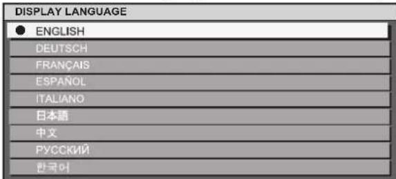
● Various menus, settings, adjustment screens, control button names, etc., are displayed in the selected language.
● Languages can be selected from English, German, French, Spanish, Italian, Japanese, Chinese, Russian, and Korean.
Note
● The on-screen display language of the projector is set to English by default.
Select [DISPLAY OPTION] from the main menu, and select the item from the sub-menu.
Refer to "Navigating through the menu"
(→ page 41) regarding the operation of the menu screen.
● After selecting the item, press ▲▼◀▶ to set.
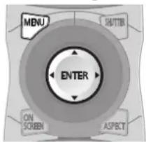
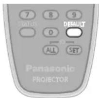
[COLOR MATCHING]
You can correct the color difference between the sets when multiple sets are to be used simultaneously.
1) Press ▲▼ to select [COLOR MATCHING].
2) Press ◀▶ to switch [COLOR MATCHING].
● The setting will change as follows each time you press the button.
![PANASONIC PT-DW730U - [COLOR MATCHING] - 1](/content/2026/06/1201863/images/94d719e72974ad728b818ea856c4f54cad7813800184578ccb408324fc5abdfd.jpg)
flowchart
graph TD
    A["[OFF"] [3COLORS]] <--> B["[MEASURED"]]
    B <--> C["[7COLORS"]]
| [OFF] | Color matching adjustment is not carried out. |
| [3COLORS] | [RED], [GREEN], and [BLUE] can be adjusted. |
| [7COLORS] | [RED], [GREEN], [BLUE], [CYAN], [MAGENTA], [YELLOW], and [WHITE] can be adjusted. |
| [MEASURED] | Refer to “Adjusting the color matching using a colorimeter” (→ page 56) regarding details about this mode. |
■If [3COLORS] or [7COLORS] was selected in Step 2)
3) Press the button.
● The [3COLORS] or [7COLORS] screen is displayed.
4) Press ▲▼ to select [RED], [GREEN], or [BLUE] (if [7COLORS] was selected, select [RED], [GREEN], [BLUE], [CYAN], [MAGENTA], [YELLOW], or [WHITE]).
5) Press the button.
- The [3COLORS:RED], [3COLORS:GREEN], [3COLORS:BLUE], or [3COLORS:WHITE] screen is displayed.
In case of the [7COLORS], [7COLORS:RED], [7COLORS:GREEN], [7COLORS:BLUE], [7COLORS:CYAN], [7COLORS:MAGENTA], [7COLORS:YELLOW], or [7COLORS:WHITE] screen is displayed.
6) Press ◀▶ to adjust the level.
- The adjustment values will change between [0]^1 and [2048].
*1: The minimum values differ depending on the color to adjust.
Note
- Operation when correcting the adjustment color
When the correction color same as the adjustment color is changed:
Luminance of the adjustment color will change. When correction color red is changed: Red is added to or subtracted from the adjustment color. When correction color green is changed: Green is added to or subtracted from the adjustment color. When correction color blue is changed: Blue is added to or subtracted from the adjustment color.
● This adjustment should be carried out by a person who is familiar with the projector or by a service person because a high level of skill is required to make a successful adjustment.
- Pressing the button will restore the factory default settings for all items.
- When any setting other than [OFF] has been selected for [COLOR MATCHING], [AI] and [COLOR CORRECTION] are fixed to [OFF], and [COLOR TEMPERATURE] is fixed to [USER]. (However, [WHITE BALANCE HIGH] cannot be adjusted.)
■Adjusting the color matching using a colorimeter
[RED], [GREEN], [BLUE], [CYAN], [MAGENTA], [YELLOW], and [WHITE] can be set to preferred colors using the colorimeter that can measure the chromaticity coordinates and luminance.
1) Press ▲▼ to select [COLOR MATCHING].
2) Press ◀▶ to select [MEASURED].
3) Press the button.
● The [MEASURED MODE] screen is displayed.
4) Press ▲▼ to select [MEASURED DATA].
5) Press the button.
● The [MEASURED DATA] screen is displayed.
6) Measure the luminance (Y) and the chromaticity coordinates (x, y) using the colorimeter.
7) Press ▲▼ to select a color, and press ◀▶ to adjust the setting.
8) Once all the input is completed, press the
- Inputting the coordinates of a desired color
1) Press ▲▼ to select [TARGET DATA].
2) Press the button.
● The [TARGET DATA] screen is displayed.
3) Press ▲▼ to select the desired colors, and press ◀▶ to input their coordinates.
4) Once all the input is completed, press the
Note
- Correct colors cannot be displayed when the target data is out of the color range for the projector.
- When [AUTO TESTPATTERN] is set to [ON], adjustment test pattern for the selected adjustment color is automatically displayed.
- When measuring the measurement data using a measurement device such as a colorimeter, start the measurement after setting [PICTURE MODE] to [DYNAMIC].
- There may be differences between the chromaticity coordinates of the target data and measured values of the colorimeter depending on the measurement device used and measurement environment.
[COLOR CORRECTION]
You can adjust and register colors by input signals.
1) Press ▲▼ to select [COLOR CORRECTION].
2) Press ◀▶ to switch [COLOR CORRECTION].
| [OFF] Standard setting |
| [USER] | The six colors of red, green, blue, cyan, magenta, and yellow can be adjusted and registered for each of the four signal methods of VIDEO, S-VIDEO, RGB, and YP_BP_R/YC_BC_R . Set the details by pressing thebutton. |
[CONTRAST MODE]
There are two types of contrast modes. Set in accordance with the environment of usage.
1) Press ▲▼ to select [CONTRAST MODE].
2) Press ◀▶ to switch [CONTRAST MODE].
| [NORMAL] Sets the brightness to maximum. |
| [HIGH] Sets the contrast to maximum. |
[SCREEN SETTING]
You can set the screen size.
You can correct to the optimal image position matching to the set screen when the aspect ratio of the projected image is changed. Set in accordance with the screen used.
1) Press ▲▼ to select [SCREEN SETTING].
2) Press the button.
● The [SCREEN SETTING] screen is displayed.
3) Press ◀▶ to switch [SCREEN FORMAT].
PT-DW730U
[16:10] [16:9]
PT-DX800U
[4:3] [16:9]→
4) Press ▲▼ to select [SCREEN POSITION].
5) Press ◀▶ to adjust [SCREEN POSITION].
- In case of PT-DW730U, vertical positions can be adjusted between -40 and +40.
- In case of PT-DX800U, vertical positions can be adjusted between -96 and +96.
Note
- [SCREEN POSITION] cannot be adjusted when [SCREEN FORMAT] is set to [16:10] for PT-DW730U, and when [SCREEN FORMAT] is set to [4:3] for PT-DX800U.
[AUTO SIGNAL]
Image display positions can be automatically adjusted without pressing the button on the remote control every time, in cases that an unregistered signal is to be input frequently in a situation such as a conference.
1) Press ▲▼ to select [AUTO SIGNAL].
2) Press ◀▶ to switch [AUTO SIGNAL].
[OFF] [ON]
| [OFF] Turns off the auto signal function. |
| [ON] | Automatic setup is executed automatically when the projected image is changed to an unregistered signal. |
[AUTO SETUP]
You can set when adjusting a special signal or horizontally long (16:9, etc.) signal.
1) Press ▲▼ to select [AUTO SETUP].
2) Press the button.
● The [AUTO SETUP] screen is displayed.
3) Press ◀▶ to switch [MODE].
- The setting will change as follows each time you press the button.
![PANASONIC PT-DW730U - [AUTO SETUP] - 1](/content/2026/06/1201863/images/597c246c23bed28af67c62a1974e0381b7662ee7311b3ae689fc784f96dd5334.jpg)
flowchart
graph LR
    A["[DEFAULT"] [WIDE] [USER]] <--> B[" "]
| [DEFAULT] | Select when receiving a signal with the image aspect ratio of 4:3 or 5:4. (applicable resolution, 640 x 400, 640 x 480, 800 x 600, 832 x 624, 1 024 x 768, 1 152 x 864, 1 152 x 870, 1 280 x 960, 1 280 x 1 024, 1 600 x 1 200, 1 400 x 1 050.) |
| [WIDE] | Select when receiving a signal with wide image aspect ratio. (applicable resolution, 1 280 x 720, 1 280 x 800, 1 440 x 900, 1 680 x 1 050, 1 920 x 1 080, 1 920 x 1 200.) |
| [USER] | Select when receiving a signal with a special horizontal resolution (number of display dots). |
■When selecting [DEFAULT] or [WIDE] in Step 3)
- Automatic adjustment is executed. [PROGRESS] is displayed while automatically adjusting. When the adjustment is complete, the system returns to the [AUTO SETUP] screen.
■When selecting [USER] in Step 3)
4) Press ▲▼ to select [DISPLAY DOTS] and press ◀▶ to adjust [DISPLAY DOTS] to the horizontal resolution of the signal source.
5) Press ▲▼ to select [MODE].
6) Press the button.
- Automatic adjustment is executed. [PROGRESS] is displayed while automatically adjusting. When the adjustment is complete, the system returns to the [AUTO SETUP] screen.
[DVI-D IN]
You can switch the setting when the external equipment is connected to the terminal of the projector and the image is not projected correctly.
1) Press ▲▼ to select [DVI-D IN].
2) Press the button.
● The [DVI-D IN] screen is displayed.
3) Press ▲▼ to select [DVI EDID].
4) Press ◀▶ to switch [DVI EDID].
- The setting will change as follows each time you press the button.
![PANASONIC PT-DW730U - [DVI-D IN] - 1](/content/2026/06/1201863/images/f1020e44a5e0d18b0d6ee51dbbb78a3daa3549baaff115850e35493b6e73c997.jpg)
flowchart
graph LR
    A["[EDID3"] [EDID1] [EDID2:PC]] <--> B[" "]
| [EDID3] | Switch between fine settings for a moving image and for a still image. |
| [EDID1] | Select this mainly when an external device (DVD player, etc.) for outputting video signals of a moving image system is connected to DVI-D IN. |
| [EDID2:PC] | Mainly use this when an external device (PC, etc.) for outputting video signals of a still image system is connected to DVI-D IN. |
5) Press ▲▼ to select [DVI SIGNAL LEVEL].
6) Press ◀▶ to switch [DVI SIGNAL LEVEL].
- The setting will change as follows each time you press the button.
[0-255:PC] [16-235]
| [0-255:PC] | Select when the external equipment (computers, etc.) is connected via DVI terminal output. |
| [16-235] | Select when the external equipment (DVD players, etc.) is connected via HDMI terminal output using a conversion cable, etc. |
Note
- The optimal setting is different depending on the output setting of the connected external equipment. Refer to the instruction manual of the external equipment regarding the output of the external equipment.
- The data for Plug and play will change when the setting is changed. Refer to “List of compatible signals” (▶ page 102) for the resolution supporting the Plug and play.
[ON-SCREEN DISPLAY]
You can set the on-screen display.
1) Press ▲▼ to select [ON-SCREEN DISPLAY].
2) Press the button.
● The [ON-SCREEN DISPLAY] screen is displayed.
3) Press ▲▼ to select an item, and press ◀▶ to change the setting.
[OSD POSITION]
Set the position of the menu screen (OSD).
- The setting will change as follows each time you press the button.
![PANASONIC PT-DW730U - [OSD POSITION] - 1](/content/2026/06/1201863/images/12309f58ea7928b8ed99689da5df25a3f52db647c2721c3ac6838e9593ee0afa.jpg)
flowchart
graph TD
    A["1"](Top left of the screen) --> B["2"](Center left of the screen)
    B --> C["3"](Bottom left of the screen)
    C --> D["4"](Top center of the screen)
    D --> E["5"](Center of the screen)
    E --> F["6"](Bottom center of the screen)
    F --> G["7"](Top right of the screen)
    G --> H["8"](Center right of the screen)
    H --> I["9"](Bottom right of the screen)
    I --> A
[OSD DESIGN]
You can set the color of the menu screen (OSD).
- The setting will change as follows each time you press the button.
![PANASONIC PT-DW730U - [OSD DESIGN] - 1](/content/2026/06/1201863/images/85675fc93fdfcb28cb59c4d5b3f7b8061f37e2cac3426fb6bd9e1277c5823702.jpg)
flowchart
graph TD
    A["[1"]: Yellow["2"]: Blue] --> B["[6"]: Brown["3"]: White]
    B --> C["[5"]: Pink["4"]: Green]
    C --> B
[OSD MEMORY]
You can be set whether to maintain the cursor position of the menu screen (OSD).
- The setting will change as follows each time you press the button.
![PANASONIC PT-DW730U - [OSD MEMORY] - 1](/content/2026/06/1201863/images/a388c379c1ab92dd2d9a1905ba1526fcea9e45e43d35feed71691f30fac65e05.jpg)
Note
- The cursor position will not be maintained when the switch of the projector body is set to , even if it is set to [ON].
You can set to display the input terminal name currently selected in the position set by the [OSD POSITION].
● The setting will change as follows each time you press the button.
![PANASONIC PT-DW730U - [INPUT GUIDE] - 1](/content/2026/06/1201863/images/5bb1811ad5ece49c0e3b10fbbc7b1add99ea9aa4467bc82bf34ee863b1395f58.jpg)
■[WARNING MESSAGE]
You can set the display/hide of the warning message.
● The setting will change as follows each time you press the button.
![PANASONIC PT-DW730U - ■[WARNING MESSAGE] - 1](/content/2026/06/1201863/images/162f570be242813277000c8e975379ca4a06e21e5da7f3b185add9eced23157a.jpg)
[BACK COLOR]
You can set the color of the projected image when there is no signal input.
1) Press ▲▼ to select [BACK COLOR].
2) Press ◀▶ to switch [BACK COLOR].
● The setting will change as follows each time you press the button
![PANASONIC PT-DW730U - [BACK COLOR] - 1](/content/2026/06/1201863/images/d601bbf493f45ec79efbb5db6ac24b7d390fca302bb4fc9edd1ab7645db8f184.jpg)
flowchart
graph TD
    A["[BLUE"] [BLACK]] --> B[" "]
    C["[DEFAULT LOGO"] [USER LOGO]] --> D[" "]
    A <--> C
| [BLUE] | The entire projection area appears blue. |
| [BLACK] | The entire projection area appears black. |
| [USER LOGO] | The picture registered by the user is projected. |
| [DEFAULT LOGO] | The Panasonic logo is projected. |
Note
- Separate software "Logo Transfer Software" is required to create and register the pictures of [USER LOGO]. Refer to the application software download from the website support information (http://panasonic.net/avc/projector/software/).
[STARTUP LOGO]
You can set the logo display when the power is turned on.
1) Press ▲▼ to select [STARTUP LOGO].
2) Press ◀▶ to switch [STARTUP LOGO].
- The setting will change as follows each time you press the button.
![PANASONIC PT-DW730U - [STARTUP LOGO] - 1](/content/2026/06/1201863/images/e91299ca1c933a8ea453d571e7792205cbc4536a31ada4d9eef55bea64969107.jpg)
flowchart
graph TD
    A["DEFAULT LOGO"] --> B["NONE"]
    B --> C["USER LOGO"]
    C <--> A
| [DEFAULT LOGO] | The Panasonic logo is projected. |
| [NONE] No startup logo is projected. |
| [USER LOGO] | The picture registered by the user is projected. |
Note
● The startup logo will disappear in approximately 15 seconds.
- Separate software “Logo Transfer Software” is required to create and register the pictures of [USER LOGO]. Refer to the application software download from the website support information (http://panasonic.net/avc/projector/software/).
[FREEZE]
The projected image is paused temporarily regardless of the playback of the external equipment.
1) Press ▲▼ to select [FREEZE].
2) Press the button.
- To cancel the freeze, press the
[SIDE BY SIDE] (PT-DW730U only)
Two different input signals can be displayed simultaneously.
1) Press ▲▼ to select [SIDE BY SIDE].
2) Press the button.
● Two images are displayed.
![PANASONIC PT-DW730U - [SIDE BY SIDE] (PT-DW730U only) - 1](/content/2026/06/1201863/images/d45355b77612a60bcce011efee7ae7f8913028a7b1ecbb34f50b67248faa6c5c.jpg)
flowchart
graph LR
    A["Input A Input A"] --> B["Output B"]
    style A fill:#ccc
    style B fill:#ccc
    style C fill:#ccc
    style D fill:#ccc
    style E fill:#ccc
    style F fill:#ccc
    style G fill:#ccc
    style H fill:#ccc
    style I fill:#ccc
    style J fill:#ccc
    style K fill:#ccc
    style L fill:#ccc
    style M fill:#ccc
    style N fill:#ccc
    style O fill:#ccc
    style P fill:#ccc
    style Q fill:#ccc
    style R fill:#ccc
    style S fill:#ccc
    style T fill:#ccc
    style U fill:#ccc
    style V fill:#ccc
    style W fill:#ccc
    style X fill:#ccc
    style Y fill:#ccc
    style Z fill:#ccc
3) Press the
- To cancel the two window display, select [OFF] and press the button.
● [FREEZE] will be set against the input A side.
- The adjustment and setting of the menu items cannot be performed during the two window display.
- Values for the input A side will be applied for the [PICTURE] settings. (Values for both input A and input B will be applied for [CONTRAST], [BRIGHTNESS], [COLOR], [TINT], and [SHARPNESS].)
- The two window display will maintain the aspect ratio selected using the button on the remote control or the [ASPECT] setting.
- The two window display may not be available depending on the combination of the input signals. Refer to "Two window display combination list (PT-DW730U only)" (→ page 101) for details.
Select [PROJECTOR SETUP] from the main menu, and select the item from the sub-menu. Refer to "Navigating through the menu"
(→ page 41) regarding the operation of the menu screen.
● After selecting the item, press ▲▼◀▶ to set.


[PROJECTOR ID]
The projector has an ID number setting function, and simultaneous control or individual control is possible with one remote control when multiple projectors are used side by side.
1) Press ▲▼ to select [PROJECTOR ID].
2) Press ◀▶ to switch [PROJECTOR ID].
● The setting will change as follows each time you press the button.
![PANASONIC PT-DW730U - [PROJECTOR ID] - 1](/content/2026/06/1201863/images/77f37e0010e2fdfe128bf951fdf0edd1e2d1e466ccb3bf01235e357a6e9e7616.jpg)
flowchart
graph TD
    A["[ALL"] [1]] <--> B[" "]
    C["[64"] [2]] <--> D[" "]
Note
- The ID number can be set to [ALL] or [1] through [64].
- The ID number of the remote control needs to be matched with the ID number of the projector when the ID number is specified.
- When the ID number is set to [ALL], the projector will operate regardless of what number it is set on the remote control or the computer.
If multiple projectors are used and some of them have their IDs set to [ALL], they cannot be controlled separately from the projectors with other ID numbers.
- Refer to "Setting Remote control ID numbers" (→ page 20) regarding the method to set the ID number on the remote control.
[PROJECTION METHOD]
You can set the projection method in accordance with the installation status of the projector.
Change the projection method if the screen display is upside down or inverted.
1) Press ▲▼ to select [PROJECTION METHOD].
2) Press the button.
● The [PROJECTION METHOD] screen is displayed.
3) Press ▲▼ to select the projection method.
| [FRONT/FLOOR] | When installing on the desk, etc., in front of the screen |
| [FRONT/CEILING] | When installing using the ceiling mount bracket (optional accessories) in front of the screen |
| [REAR/FLOOR] | When installing on the desk, etc., behind the screen (using a translucent screen) |
| [REAR/CEILING] | When installing using the ceiling mount bracket (optional accessories) behind the screen (using a translucent screen) |
4) Press the button.
5) When the confirmation is displayed, select [OK] or [CANCEL], and press the button.
Attention
- When [PROJECTION METHOD] is changed, confirm that [COOLING CONDITION] page 62) is set correctly.
[HIGH ALTITUDE MODE]
If you use the projector at elevations (1 400 m (4 593 ft) to 2 700 m (8 858 ft)), the [HIGH ALTITUDE MODE] setting needs to be [ON].
1) Press ▲▼ to select [HIGH ALTITUDE MODE].
2) Press ◀▶ to switch [HIGH ALTITUDE MODE].
● The setting will change as follows each time you press the button.
![PANASONIC PT-DW730U - [HIGH ALTITUDE MODE] - 1](/content/2026/06/1201863/images/a01683d8a0a5532b762f6e66f8002a2d5c4de7de461ed2731250c215a57a51c7.jpg)
| [OFF] | When using at a place lower than 1 400 m (4 593 ft) above sea level |
| [ON] | When using at a high altitude (1 400 m (4 593 ft) or higher and lower than 2 700 m (8 858 ft) above sea level) |
3) When the confirmation is displayed, select [OK] or [CANCEL], and press the button.
Note
- The speed of the fan is raised and the operation sound will become louder when this is set to [ON].
[COOLING CONDITION]
You can change the fan control depending on the direction of projection.
Set [COOLING CONDITION] correctly in accordance with the direction of projection referencing the following figure. It may shorten the life of the lamp if used in incorrect setting.
1) Press ▲▼ to select [COOLING CONDITION].
2) Press the button.
● The [COOLING CONDITION] screen is displayed.
3) Press ▲▼ to select the cooling condition.
![[VERTICAL UP SETTING] [FLOOR SETTING] [CEILING SETTING] 30° 30° [VERTICAL DOWN SETTING] : Projection direction](/content/2026/06/1201863/images/3c4e5a4d2ad97a4a736672d3bde4654d5417927d46363a7012f720b62b7a5d34.jpg)
4) Press the button.
5) When the confirmation is displayed, select [OK] or [CANCEL], and press the button.
[LAMP SELECT]
You can set the brightness using the two luminous lamps built inside the projector to dual-lamp or single-lamp brightness in accordance with the condition or purpose of the usage. Setting [SINGLE] automatically switches the lamp to be turned on based on the duration of use.
1) Press ▲▼ to select [LAMP SELECT].
2) Press ◀▶ to switch [LAMP SELECT].
- The setting will change as follows each time you press the button.
![PANASONIC PT-DW730U - [LAMP SELECT] - 1](/content/2026/06/1201863/images/cfbe64373ae8a6c4ab4c2f04cc15db11d2b8f52e844fb9c1607bbda07921a0a5.jpg)
flowchart
graph TD
    A["[DUAL"] [SINGLE]] <--> B["[LAMP2"] [LAMP1]]
    B <--> C["←"]
    C --> A
| [DUAL] | Two lamps will light. |
| [SINGLE] | One lamp will light. (The lamp with shorter duration of use is automatically selected.) |
| [LAMP1] Lamp unit 1 will light continuously. |
| [LAMP2] Lamp unit 2 will light continuously. |
Note
- In the [SINGLE], [LAMP1] or [LAMP2] mode, one lamp remains off or the currently active lamp exceeds 2 000 hours of cumulative operating time (when [HIGH] is selected as the [LAMP POWER] setting), the other lamp will light. In the [DUAL] mode, one lamp remains off or the currently active lamp exceeds 2 000 hours of cumulative operating time (when [HIGH] is selected as the [LAMP POWER] setting), the other lamp alone will light. However, if both lamps remain off or the 2 000 hours of cumulative operating time (when [HIGH] is selected as the [LAMP POWER] setting).
● The text colors of the items indicate the status.
Green → Current setting
Yellow → Current setting
(When there is a lamp that cannot turn on or failed to turn on)
Red → Lamp that has failed to turn on
White → Any other status
- If the projector is repeatedly used for short periods of time, the lamps will need to be replaced more frequently.
[LAMP RELAY]
The degradation of the lamp due to continuous usage can be reduced by automatically switching the lamp to be turned on when using the projector continuously for 22 hours or more.
1) Press ▲▼ to select [LAMP RELAY].
2) Press ◀▶ to switch [LAMP RELAY].
● The time setting to switch the lamp will change as follows each time you press the button.
![PANASONIC PT-DW730U - [LAMP RELAY] - 1](/content/2026/06/1201863/images/4a57170afc1501c57cac5139948e24e6c7d7a3ef7e8c51b1fa99921060c3c0e8.jpg)
flowchart
graph TD
    A["[OFF"] [00:00]] --> B[" "]
    C["[23:00"] [01:00]] --> D[" "]
    style A fill:#fff,stroke:#000
    style C fill:#fff,stroke:#000
    style B fill:#fff,stroke:#000
    style D fill:#fff,stroke:#000
    note right of A "(Every one hour)"
Note
- The “LAMP RELAY” function will be enabled when [LAMP SELECT] is set to [DUAL] or [SINGLE].
- Only one lamp is turned on for four hours after the set time when [LAMP SELECT] is set to [DUAL].
● The operating time will be the local time.→ page 65)
[LAMP POWER]
You can switch the brightness of the lamp in accordance with the environment or purpose of usage of the projector.
1) Press ▲▼ to select [LAMP POWER].
2) Press ◀▶ to switch [LAMP POWER].
● The setting will change as follows each time you press the button.
![PANASONIC PT-DW730U - [LAMP POWER] - 1](/content/2026/06/1201863/images/0424d72a3dee3a139092583870f1db9cbb95379ca947d26a6b471942dc153522.jpg)
| [HIGH] | Set when high luminance is necessary. |
| [LOW] | Set when high luminance is not necessary. |
Note
- When set to [LOW], the reduction of power consumption, less operation sound, and longer life of the lamp can be achieved.
[STANDBY MODE]
You can set the power consumption during the standby.
1) Press ▲▼ to select [STANDBY MODE].
2) Press ◀▶ to switch [STANDBY MODE].
● The setting will change as follows each time you press the button
![PANASONIC PT-DW730U - [STANDBY MODE] - 1](/content/2026/06/1201863/images/15bde238a00cd1327667da9ade7db5fdc8698e8cc584b60c954c86cf125ef10e.jpg)
Note
- When set to [ECO], the network function and the terminal is not available during the standby. Also, some of the RS-232C command will not be available. When set to [NORMAL], the network function and the terminal will be available during the standby.
- When set to [ECO], the time it takes to start the projection may become approximately ten seconds slower than compared to when set to [NORMAL].
[RS-232C]
You can set the communication condition of the / terminals.
1) Press ▲▼ to select [RS-232C].
2) Press the button.
3) Press ▲▼ to select the communication condition.
4) Press ◀▶ to set it.
Note
- Refer to "Serial terminal" (→ page 98).
[REMOTE2 MODE]
You can set the terminal.
1) Press ▲▼ to select [REMOTE2 MODE].
2) Press ◀▶ to switch [REMOTE2 MODE].
- The setting will change as follows each time you press the button.
[DEFAULT] [USER]
| [DEFAULT] | The pin assignment of theterminal is used by the factory default setting of the projector.(→ page 100) |
| [USER] | Used to change the setting of theterminal. |
■When selecting [USER] in Step 2)
3) Press the button.
4) Press ▲▼ to select an item from [PIN2] to [PIN8], and press ◀▶ to switch the setting.
[STATUS]
Displays the status of the projector.
1) Press ▲▼ to select [STATUS].
2) Press the button.
3) Press ◀▶ to switch the pages.
| [INPUT] | Displays the input terminal currently selected. |
| [NAME] Displays the input signal name. |
| [SIGNAL FREQUENCY] | Displays the frequency of the input signal. |
| [PROJECTOR RUNTIME] | Displays the operation hours of the projector. |
| [LAMP1]*1 | Displays the lighting time of the lamp 1. |
| [LAMP2]*1 | Displays the lighting time of the lamp 2. |
| [INTAKE AIR TEMP.] | Displays the status of the air intake temperature of the projector. |
| [OPTICS MODULE TEMP.] | Displays the status of the internal temperature of the projector. |
| [AROUND LAMP TEMP.] | Displays the status of the temperature around the lamps of the projector. |
| [PROJECTOR TYPE] | Displays the type of the projector. |
| [SERIAL NUMBER] | Displays the serial number of the projector. |
| [LAMP UNIT MODEL NO.] | Displays the model no. of the lamp unit. |
| [LAMP1 SERIAL NUMBER] | Displays the serial number of the lamp 1. |
| [LAMP2 SERIAL NUMBER] | Displays the serial number of the lamp 2. |
| [MAIN VERSION] | Displays the main version of the firmware of the projector. |
| [SUB VERSION] | Displays the sub version of the firmware of the projector. |
| [NETWORK VERSION] | Displays the network version of the projector. |
| [ON COUNT] | ● [POWER ON TIMES]: Displays the number of times the power is turned on. ● [LAMP1 ON]: Displays the number of times the lamp 1 is turned on. ● [LAMP2 ON]: Displays the number of times the lamp 2 is turned on. ● [SHUTTER]: Displays the number of times the shutter function is used. |
| [LAMP1] | Displays the details of the usage time. |
| [LAMP2] | Displays the details of the usage time. |
| [NUMBER OF ENTRY SIGNAL] | Displays the number of registered signals. |
| [REMOTE2 STATUS] | Displays the control status of the REMOTE2. |
*1: The lamp lighting time displayed is actual time. The following conversion is required to calculate the guideline for lamp replacement.
Time to replace the lamp =
The usage time when [LAMP POWER] is set to [HIGH] +
(the usage time when [LAMP POWER] is set to [LOW] x 2 ÷ 3)
Note
- The contents of the status can be sent via E-mail when the button is pressed while the status is displayed.
[NO SIGNAL SHUT-OFF]
You can set the power of the projector automatically to standby if there is no input signal by the specified time.
1) Press ▲▼ to select [NO SIGNAL SHUT-OFF].
2) Press ◀▶ to switch [NO SIGNAL SHUT-OFF].
| [DISABLE] | Disables [NO SIGNAL SHUT-OFF]. |
| [10MIN.] - [90MIN.] | Allows you to set in ten minute intervals. |
You can set the button on the remote control.
1) Press ▲▼ to select [FUNCTION BUTTON].
2) Press the button.
3) Press ▲▼ to select the function.
| [DISABLE] | Disables thebutton. |
| [SUB MEMORY] | Switches the sub memory.(→ page 69) |
| [SYSTEM SELECTOR] | Switches the setting for [SYSTEM SELECTOR]. (→ page 47) |
| [SYSTEM DAYLIGHT VIEW] | Switches the setting for [SYSTEM DAYLIGHT VIEW]. (→ page 46) |
| [FREEZE] | Freezes the image temporarily.(→ page 60) |
| [SIDE BY SIDE]*1 | Switches to two window display.(→ page 60) |
*1: Only for PT-DW730U
4) Press the button.
[DATE AND TIME]
You can set the time zone, date, and time of the built-in clock of the projector.
1) Press ▲▼ to select [DATE AND TIME].
2) Press the button.
3) Press ▲▼ to select [TIME ZONE].
4) Press ◀▶ to switch [TIME ZONE].
5) Press ▲▼ to select [ADJUST CLOCK].
6) Press the button.
● The [ADJUST CLOCK] screen is displayed.
7) Press ▲▼ to select the item to be set, and press ◀▶ to set the local date and time.
8) Press ▲▼ to select [APPLY], and press the button.
● The setting of the time will be completed.
[SAVE ALL USER DATA]
You can save the various setting values as a backup in the built-in memory of the projector.
1) Press ▲▼ to select [SAVE ALL USER DATA].
2) Press the button.
● The [SECURITY PASSWORD] screen is displayed.
3) Enter the security password and press the button.
4) When the confirmation is displayed, select [OK] or [CANCEL], and press the button.
● While data is saved, [PROGRESS] is displayed.
Note
- The setting of the image registered in [USER LOGO] will not be saved.
[LOAD ALL USER DATA]
You can load the various setting values saved as a backup in the built-in memory of the projector.
1) Press ▲▼ to select [LOAD ALL USER DATA].
2) Press the button.
● The [SECURITY PASSWORD] screen is displayed.
3) Enter the security password and press the button.
4) When the confirmation is displayed, select [OK] or [CANCEL], and press the button.
Note
- The projector will go into the standby status to reflect the setting values when [LOAD ALL USER DATA] is executed.
[INITIALIZE]
You can return various setting values to their factory default settings.
1) Press ▲▼ to select [INITIALIZE].
2) Press the button.
● The [SECURITY PASSWORD] screen is displayed.
3) Enter the security password and press the button.
● The [INITIALIZE] screen is displayed.
4) Press ▲▼ to select the item to initialize.
| [ALL USER DATA] | Restores all the setting values including the registered signal, the network settings, E-mail settings, and the logo image to their factory default settings.The projector will go into the standby status to reflect the setting values. |
| [ENTRY SIGNAL] | Deletes all the setting values saved for each input signal.To delete only a part of the registered signal, perform the procedure described in “Deleting a registered data” (→ page 68). |
| [NETWORK/E-MAIL] | Restores the network settings and the E-mail settings to their factory default settings. |
| [LOGO IMAGE] | Deletes the image registered in [USER LOGO]. |
5) Press the button.
6) When the confirmation is displayed, select [OK] or [CANCEL], and press the button.
[SERVICE PASSWORD]
Used by a service person.
Select [TEST PATTERN] from the main menu. Refer to "Navigating through the menu"
(→ page 41) regarding the operation of the menu screen.
- Press ◀▶ to switch.

[TEST PATTERN]
Displays the test pattern built-in to the projector. Results of position setting, size, etc. will not be reflected in the test patterns. Make sure to display the input signal before performing various adjustments.
Press ◀▶ to switch the various test patterns.
■Display sequence of internal test patterns
The setting will change as follows each time you press ◀▶.

flowchart
graph TD
    A["Menu screen + Entry screen"] <--> B["Menu screen + Focus"]
    C["Menu screen + All white"] <--> D["Menu screen + All black"]
    E["Menu screen + Color bar (horizontal)"] <--> F["Menu screen + Color bar (vertical)"]
    G["Menu screen + Flag (inversion)"] <--> H["Menu screen + Window (inversion)"]
    I["Menu screen + Window"] <--> J["Menu screen + Window"]
Note
- Press the button on the remote control while the test pattern is displayed to hide the menu screen.
Select [SIGNAL LIST] from the main menu. Refer to "Navigating through the menu"
(→ page 41) regarding the operation of the menu screen.
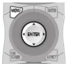

■Registered signal status
- The name can be set for each sub memory (→ page 69).
● Memory number: A1 (1-2)
↑
Sub memory number
When the address number (A1, A2, ... H7, H8) is registered
Registering a signal to the list
After a new signal is input and the
- Up to 96 signals including the sub memories can be registered to the projector.
- There are 12 pages (eight memories of A through L, with eight memories possible on each page) for memory numbers, and it is registered to the lowest number that is available. If there is no available memory number it will be overwritten from the oldest signal.
● The registration names are automatically determined by the input signals and the memory numbers.
- If a menu is being displayed, the new signals will be registered at the instant they are input.
Renaming the registered data
1) Press ▲▼◀▶ to select the signal to display the details.
2) Press the button.
● The [REGISTERED SIGNAL STATUS] screen is displayed.
- The name, memory number, input terminal, frequency, synchronization signal, etc., of the input signal are displayed.
- Press the
- The sub memory registration confirmation screen is displayed if the sub memory is not registered. Go to Step 3).
● A list of sub memories registered to the signal currently input is displayed.
- By selecting [SUB MEMORY] in the [PROJECTOR SETUP] menu [FUNCTION BUTTON], the button can be used instead of ◀▶.
2) Press ▲▼◀▶ to select the sub memory number to register in [SUB MEMORY LIST].
3) Press the button.
● The [RENAME] screen is displayed.
4) Press ▲▼◀▶ to select [OK] and press the button.
- To rename the registered data, follow the procedure in Steps 4) and 5) in "Renaming the registered data" (→ page 68).
■Switching to the sub memory list
1) Press ◀▶ on the normal screen (when the menu is not displayed).
- A list of sub memories registered to the signal currently input is displayed.
2) Press ▲▼◀▶ to select the signal to switch in [SUB MEMORY LIST].
3) Press the button.
- It will switch to the signal selected in Step 2).
■Deleting the sub memory data
1) Press ◀▶ on the normal screen (when the menu is not displayed).
● The [SUB MEMORY LIST] screen is displayed.
2) Press ▲▼◀▶ to select the sub memory number to delete and press the button.
● The [ENTRY SIGNAL CLEAR] screen is displayed.
- To cancel the deletion, press the
- The entered password is displayed with * mark on the screen.
- An error message is displayed on the screen when the entered password is incorrect. Re-enter the correct password.
[DISPLAY SETTING]
You can overlap the security message (text or image) over the projecting image.
1) Press ▲▼ to select [DISPLAY SETTING].
2) Press ◀▶ to switch [DISPLAY SETTING].
● The setting will change as follows each time you press the button.
![PANASONIC PT-DW730U - [DISPLAY SETTING] - 1](/content/2026/06/1201863/images/c5cae5b9007c1a43f3a3b5743ecbae03bfdbc21dbe7952c817350d12b44034d6.jpg)
flowchart
graph TD
    A["[OFF"] [TEXT]] <--> B[" "]
    C["[DEFAULT LOGO"]] --> D["USER LOGO"]
    C <--> C
| [OFF] The text display is disabled. |
| [TEXT] The text display is enabled. |
| [USER LOGO] | The picture registered by the user is projected. |
| [DEFAULT LOGO] | The Panasonic logo is projected. |
Note
- The logo is displayed on the whole screen in the normal projection condition when [DEFAULT LOGO] is set. Since the menu screen is displayed, it is not possible to see the whole image even if the logo display is canceled by pressing the
- Separate software "Logo Transfer Software" is required to create and register the pictures of [USER LOGO]. Refer to the application software download from the website support information (http://panasonic.net/avc/projector/software/).
[TEXT CHANGE]
You can change the text displayed when the text display is enabled by selecting [TEXT] in [DISPLAY SETTING].
1) Press ▲▼ to select [TEXT CHANGE].
2) Press the button.
● The [TEXT CHANGE] screen is displayed.
3) Press ▲▼◀▶ to select the text, and press the button to enter the text.
● Up to 22 characters can be entered.
4) Press ▲▼◀▶ to select [OK] and press the button.
● The text is changed.
You can set to enable/disable the menu operation by displaying the menu with the
- The
- The password setting is set to [OFF] at the time of purchase or when [ALL USER DATA] is initialized.
- The unlock status is maintained until the projector is set to the standby mode.
You can change the MENU LOCK PASSWORD.
1) Press ▲▼ to select [MENU LOCK PASSWORD].
2) Press the button.
- The [MENU LOCK PASSWORD] screen is displayed.
3) Press ▲▼◀▶ to select the text, and press the button to enter the text.
● Up to 16 characters can be entered.
4) Press ▲▼◀▶ to select [OK] and press the button.
- Select [CANCEL] to stop.
Attention
- The initial password when used for the first time or after initializing all the user data is "AAAA".
- Change the password periodically that is hard to guess.
[CONTROL DEVICE SETUP]
You can enable/disable the button operations on the control panel and the remote control.
1) Press ▲▼ to select [CONTROL DEVICE SETUP].
2) Press the button.
- The [CONTROL DEVICE SETUP] screen is displayed.
3) Press ▲▼ to select [CONTROL PANEL] or [REMOTE CONTROLLER].
4) Press the button.
● The [CONTROL PANEL] or [REMOTE CONTROLLER] screen is displayed.
[CONTROL PANEL]
- You can set the limitation on the control from the control panel.
| [ENABLE] | Enables the button operation from the main unit. |
| [DISABLE] | Disables the button operation from the main unit. |
■[REMOTE CONTROLLER]
- You can set the limitation on the control from the remote control.
| [ENABLE] | Enables the button operation from the remote control. |
| [DISABLE] | Disables the button operation from the remote control. |
5) Press ▲▼ to select [ENABLE] or [DISABLE], and press the button.
6) When the confirmation is displayed, select [OK] or [CANCEL], and press the button.
Note
- When a button operation is performed on the device set to [DISABLE], the [SECURITY PASSWORD] screen is displayed. Enter the security password.
- The [SECURITY PASSWORD] screen will disappear when the
- The power cannot be turned off (the standby mode cannot be set) if the operations of both [CONTROL PANEL] and [REMOTE CONTROLLER] are set to [DISABLE].
- When the setting has completed, the menu screen will disappear. To operate continuously, press the
Select [NETWORK] from the main menu, and select the item from the sub-menu.
Refer to "Navigating through the menu"
(→ page 41) regarding the operation of the menu screen.
● After selecting the item, press ▲▼◀▶ to set.


[NETWORK SETUP]
Perform the initial setting of the network before using the network function.
1) Press ▲▼ to select [NETWORK SETUP].
2) Press the button.
● The [NETWORK SETUP] screen is displayed.
3) Press ▲▼ to select an item, and change the settings according to the operation instructions of the menu.
| [PROJECTOR NAME] | Change the setting when using a DHCP server. |
| [DHCP] | Set this to [ON] when using a DHCP server to acquire the IP address automatically. Set to [OFF] when not using a DHCP server. |
| [IP ADDRESS] | Enter the IP address when not using a DHCP server. |
| [SUBNET MASK] | Enter the subnet mask when not using a DHCP server. |
| [DEFAULT GATEWAY] | Enter the default gateway address when not using a DHCP server. |
| [STORE] Save the current network settings. |
4) Press ▲▼ to select [STORE], and press the button.
5) When the confirmation is displayed, select [OK] or [CANCEL], and press the button.
Note
- When using a DHCP server, confirm that the DHCP server is running.
- Consult your network administrator regarding the IP address, subnet mask, and default gateway.
[NETWORK CONTROL]
You can set up the control method of the network.
1) Press ▲▼ to select [NETWORK CONTROL].
2) Press the button.
- The [NETWORK CONTROL] screen is displayed.
3) Press ▲▼ to select an item, and press ◀▶ to change the setting.
| [WEBCONTROL] | Set to [ON] to control with the Web browser. |
| [PJLinkCONTROL] | Set to [ON] to control with the PJLink protocol. |
| [COMMANDCONTROL] | Set to [ON] to control with the/terminal control command format (⇨ page 99).Refer to “Control commands via LAN” (⇨ page 96). |
| [COMMANDPORT] | Set the port number used for command control. |
| [STORE] | Save the current network control settings. |
4) Press ▲▼ to select [STORE], and press the button.
5) When the confirmation is displayed, select [OK] or [CANCEL], and press the button.
[NETWORK STATUS]
Displays the status of the network for the projector body.
1) Press ▲▼ to select [NETWORK STATUS].
2) Press the button.
● The [NETWORK STATUS] screen is displayed.
Network connections
The projector has a network function, and the following operations are available from the computer using the Web browser control.
- Setting and adjustment of the projector
● Display of the projector status
● Transmission of an E-mail message when there is a problem with the projector
Note
● A LAN cable is required to use the network function.

flowchart
graph TD
    A["Computer"] -->|LAN cable (straight)| B["Hub"]
    C["Projector"] -->|LAN cable (straight)| B["Hub"]
- A Web browser is required to use this function. Confirm that the Web browser can be used beforehand. Compatible OS: Windows XP/Windows Vista/Windows 7, Mac OS X v10.4/v10.5/v10.6 Compatible browser: Internet Explorer 6.0/7.0/8.0, Safari 2.0/3.0/4.0 (Mac OS)
- Communication with an E-mail server is required to use the E-mail function. Confirm that the E-mail can be used beforehand.
- Use a LAN cable that is straight-through and compatible with category 5 or higher.
- Use a LAN cable with length of 100 m or shorter.
■Name and function of network function parts

(1) LAN 10/100 lamp (yellow)
Lights on when connected to the 100BASE-TX.
(2) terminal (10BASE-T/100BASE-TX)
Used to connect the LAN cable here.
(3) LAN LINK/ACT lamp (green)
Lights on when connected.
Flashes when transmitting/receiving data.
Attention
- Connect the LAN to the indoor equipment.
Accessing from the Web browser
1) Start up the Web browser on the computer.
2) Enter the IP address set on the projector into the URL entry field of the Web browser.
3) Enter the user name and the password.
- The factory default setting of the user name is user1 (user rights)/admin1 (administrator rights) and the password is panasonic (lower case).
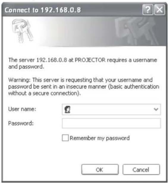
4) Click [OK].
● The [Projector status] page is displayed.

Note
- When you wish to control the projector via the Web browser, set [WEB CONTROL] to [ON] in [NETWORK CONTROL] (→ page 73).
- Do not perform setting or control simultaneously by starting up multiple Web browsers. Do not set or control the projector from multiple computers.
● Change the password first. (→ page 86)
- The administrator rights allows to use all functions. The user rights only allows to use [Projector status] (→ page 76), confirmation of the error information page (→ page 77), [Network status] (→ page 78), [Basic control] (→ page 79), and [Change password] (→ page 86).
- Access will be locked for few minutes when an incorrect password is entered three times consecutively.
■Item description
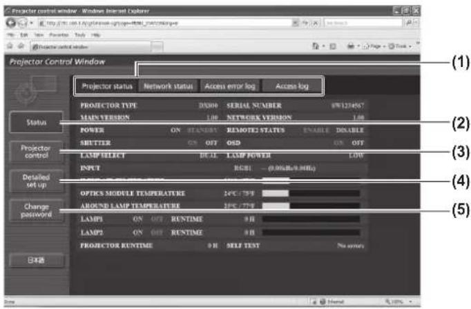
■[Projector status] page
Click [Status] → [Projector status].
Displays the status of the projector for the following items.

(1) Page switch tab
Click the tab to switch between pages.
(2) [Status]
The status of the projector is displayed by clicking this item.
(3) [Projector control]
The [Projector control] page is displayed by clicking this item.
(4) [Detailed set up]
The [Detailed set up] page is displayed by clicking this item.
(5) [Change password]
The [Change password] page is displayed by clicking this item.
(1) [PROJECTOR TYPE]
Displays the type of the projector.
(2) [MAIN VERSION]
Displays the firmware version of the projector.
(3) [POWER]
Display the power status.
(4) [SHUTTER]
Displays the shutter status.
(5) [LAMP SELECT]
Displays the [LAMP SELECT] setting ( page 62).
(6) [SERIAL NUMBER]
Displays the serial number of the projector.
(7) [NETWORK VERSION]
Displays the network firmware version.
(8) [REMOTE2 STATUS]
Displays the control status of the terminal.
(9) [OSD]
Displays the on-screen display status.
(10) [LAMP POWER]
Displays the [LAMP POWER] setting ( page 63).
(11) [INPUT]
Displays the status of the input selection.
(12) [INPUT AIR TEMPERATURE]
Displays the status of the air intake temperature of the projector.
(13) [OPTICS MODULE TEMPERATURE]
Displays the status of the internal temperature of the projector.
(14) [AROUND LAMP TEMPERATURE]
Displays the status of the temperature around the lamp of the projector.
(15) [LAMP1]/[LAMP2]/[RUNTIME]
Displays the status and the usage time of the lamp.
(16) [SELF TEST]
Displays the self-diagnosis information.
(17) [PROJECTOR RUNTIME]
Displays the operation times of the projector.
■Error information page
When [Error (Detail)] is displayed on the [Projector status] screen, click it to display the error details.
- The projector may go into the standby status to protect the projector depending on the contents of the error.
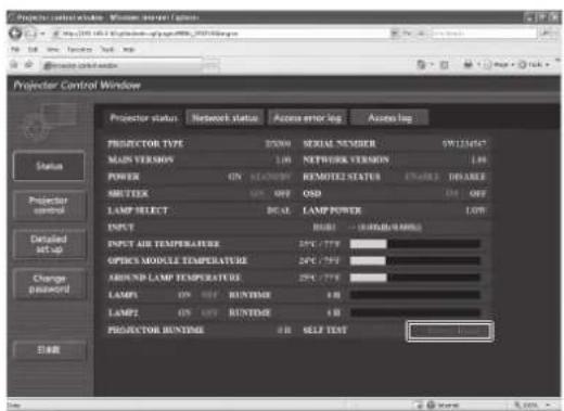
![Projector Control Window Projector control window Status Projector control Detailed set-up Change password 目标 Projector control Window Projector status Network status Access error log Access log Passion: projector clock system Dark status MAIN CPU BUS EAN OUTRAGE AIR TEMPERATURE OPTICS MODULE TEMPERATURE AMOUNT LAMP TEMPERATURE LAMP REMAIN TIME LAMP REMAIN TIME LAMP STATUS LAMP STATUS NUTTER OUTRAGE AIR TIPP SENSOR OPTICS MODULE TIPP SENSOR AMOUNT LAMP TIPP SENSOR BATTERY AMOUNT SENSOR AVG POWER [OK] [OK] [OK] [OK] [OK] [OK] [OK] [OK] [OK] [OK] [OK] [OK] [OK] [OK] [OK] [OK] [OK]](/content/2026/06/1201863/images/03b3a7ca84177719eecbede1618d73bda1c46fe936ac9a89f46f9f235dba1f62.jpg)
[OK]: Normal operation
[FAILED]: Occurrence of trouble
●Description of problem occurrence [FAILED]:
| Parameter Description | |
| [MAIN CPU BUS] | There is a problem with the microcomputer circuitry. Consult your dealer. |
| [FAN] | There is a problem with the fan or the fan drive circuit. Consult your dealer. |
| [INTAKE AIR TEMPERATURE] | The air intake temperature is too high. It may be used in an operating environment where the temperature is high, such as near a heating appliance. |
| [OPTICS MODULE TEMPERATURE] | The temperature inside the projector is high. It may be used in an operating environment where the temperature is high, such as near a heating appliance. |
| [AROUND LAMP TEMPERATURE] | The temperature around the lamp is high. The air exhaust port may be blocked. |
| [LAMP1 REMAIN TIME] | The usage time of the lamp has exceeded the specified time, and it is time to replace the lamp. |
| [LAMP2 REMAIN TIME] |
| [LAMP1 STATUS] | The lamp has failed to turn on. Wait a while until the luminous lamp cools off, and then turn on the power. |
| [LAMP2 STATUS] |
| [SHUTTER] There is a problem with the shutter circuitry. Consult your dealer. |
| [INTAKE AIR TEMP.SENSOR] | There is a problem with the sensor used to detect intake air temperature. Consult your dealer. |
| [OPTICS MODULE TEMP.SENSOR] | There is a problem with the sensor used to detect temperature inside the projector. Consult your dealer. |
| [AROUND LAMP TEMP. SENSOR] | There is a problem with the sensor used to detect exhaust air temperature. Consult your dealer. |
| [BATTERY] The battery replacement is required. Consult your dealer. |
| [AIRFLOW SENSOR] | There is a problem with the air volume sensor. Consult your dealer. |
| [COLOR WHEEL] | There is a problem with the color wheel or the color wheel drive circuit. Consult your dealer. |
| [COVER OPEN] | The attachment of the lamp unit cover is incomplete. Check the lamp unit cover. (⇨ page 92) |
| [FILTER UNIT] | The air filter unit is not attached. Check the air filter unit. (⇨ page 90) |
| [AIR FILTER] | There are too much dust accumulated in the air filter unit. Set theswitch (⇨ page 35) to, and clean the air filter (⇨ page 89). |
■[Network status] page
Click [Status] → [Network status].
The current network setting status is displayed.

■[Access error log] page
Click [Status] → [Access error log].
The error log on the WEB server is displayed such as access to the pages that do not exist or access with unauthorized user names or passwords.

■[Access log] page
Click [Status] → [Access log].
The log such as user name accessed to the WEB control page, accessed IP address, accessed time is displayed.

Note
- [Access error log]/[Access log] will display the recent few thousand accesses/requests. If many accesses/requests are made at a time, some of them may not be found in the information.
- Confirm [Access error log]/[Access log] periodically.
■[Basic control] page
Click [Projector control] → [Basic control].
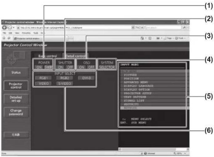
■[Detail control] page
Click [Projector control] [Detail control].
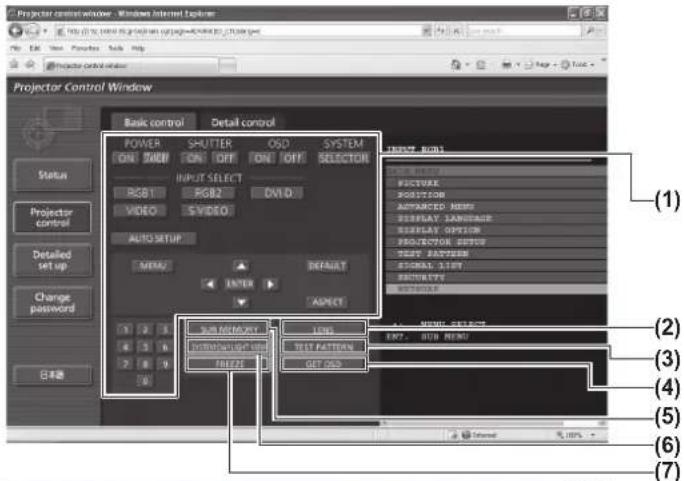

(1) [POWER] ([ON]/[STANDBY])
Switches between on/off of the power.
(2) [SHUTTER] ([ON]/[OFF])
Switches between use or not use of the shutter function.
(3) [OSD] ([ON]/[OFF])
Switches between on (display)/off (no display) of the on-screen display function.
(4) [SYSTEM] ([SELECTOR])
Switches the system method.
(5) On-screen display of the projector
The same contents as the on-screen display of the projector are displayed here. The confirmation and change of the setting contents of the menu can be performed. This is displayed even if the on-screen display function is set to off (no display).
(6) [INPUT SELECT] ([RGB1]/[RGB2]/[DVI-D]/[VIDEO]/[S-VIDEO])
Switches the input signal.
(1) Control of the projector
The projector is controlled by pressing the buttons as the buttons on the remote control. The on-screen display of the projector at the right of the control page is updated after the controlling.
(2) [LENS]
Adjusts the projection lens.
(3) [TEST PATTERN]
Displays the test pattern.
(4) [GET OSD]
Updates the on-screen display of the projector at the right of the control page.
(5) [SUB MEMORY]
Switch the sub memory
(6) [SYSTEM DAYLIGHT VIEW]
Switches the system daylight view settings.
(7) [FREEZE]
Turn the projected image to the still image temporarily.
(8) [SIDE BY SIDE] (PT-DW730U only)
Two different input signals can be displayed simultaneously.
■[Network config] page
Click [Detailed set up] → [Network config].
● The [CAUTION!] screen is displayed by clicking [Network config].
● The current settings are displayed by pressing the [Next] button.
● The following setting change screen is displayed by pressing the [Change] button.
![Projector control window - Windows Internet Explorer File Edit View Preferences Tools Help Projector control window Projector Control Window Email set up Authentication set up Network config Adjust dock Ping fast Status Projector control Detailed set up Change password Back Next IP PROJECTOR NAME PROJECTOR ● DHCP ON ● DHCP OFF IP ADDRESS 192.168.0 1 [Example: 192.168.0 100] SUBNEXTMASK 234.258.258.8 [Example: 234.258.258.8] DEFAULT GATEWAY 192.168.0 1 [Example: 192.168.0 254] DNS DNS1 [Example: 192.168.0 100.1] DNS2 [Example: 192.168.0 100.1] Back Next View Host 0, 100%](/content/2026/06/1201863/images/d564d2c615b4c5bd2edc76dae3223e58a7cb558831dbfb67f60251effee459d8.jpg)
(1) [PROJECTOR NAME]
Enter the name of the projector. Also enter the host name if it is required when using a DHCP server, etc.
(2) [DHCP ON]/[DHCP OFF]
To enable the DHCP client function, set to [DHCP ON].
(3) [IP ADDRESS]
Enter the IP address when not using a DHCP server.
(4) [SUBNETMASK]
Enter the subnet mask when not using a DHCP server.
(5) [DEFAULT GATEWAY]
Enter the gateway address when not using a DHCP server.
(6) [DNS1]
Allowed characters for the entry of DNS 1 server address (primary):
Numerics (0 - 9) and period (.)
(Example: 192.168.0.253)
(7) [DNS2]
Allowed characters for the entry of DNS 2 server address (secondary):
Numerics (0 - 9) and period (.)
(Example: 192.168.0.254)
(8) [Back]/[Next]
Press [Next] to display the setting confirmation screen. Press [Submit] to update the settings.
■[Adjust clock] page
Click [Detailed set up] → [Adjust clock].
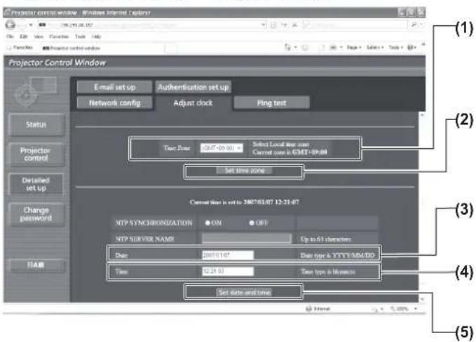
(1) [Time zone]
Selects the time zone.
(Japan is GMT +09:00)
(2) [Set time zone]
Updates the time zone setting.
(3) [Date]
Enter the date to be changed.
(4) [Time]
Enter the time to be changed.
(5) [Set date and time]
Updates the date and time settings.
Note
● The replacement of the battery inside the projector is required when the time goes out of alignment right after correcting the time. Please consult your dealer.
■[Ping test] page
You can check whether the network is connected to the E-mail server, POP server, DNS server, etc. Click [Detailed set up] → [Ping test].

(1) [Input IP address]
Enter the IP address of the server to be tested.
(2) [Submit] Executes the connection test.

(3) Example of display when the connection has succeeded
(4) Example of display when the connection has failed
■[E-mail set up] page
An E-mail message can be sent to the E-mail address setup in advance (up to two addresses) when the problem occurred or the usage time of the lamp reached the specified value.
Click [Detailed set up] → [E-mail set up].
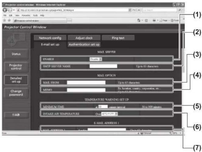

(1) [ENABLE] Select [ENABLE] when using the E-mail function.
(2) [SMTP SERVER NAME]
Enter the IP address or the server name of the E-mail server (SMTP). To enter the server name, the setup of the DNS server is required.
(3) [MAIL FROM]
Enter the E-mail address of the projector. (Up to 63 characters in single byte)
(4) [MEMO] You can enter information such as the location of the projector that notifies the sender of the E-mail. (Up to 63 characters in single byte)
(5) [MINIMUM TIME]
Change the minimum intervals for the temperature warning mail. The default value is 60 minutes. In this case, another E-mail will not be sent for 60 minutes after sending the temperature warning mail even if it reaches the warning temperature.
(6) [INTAKE AIR TEMPERATURE]
Change the temperature setting for the temperature warning mail. A temperature warning mail is sent when the temperature exceeds this value.
(7) [E-MAIL ADDRESS 1]
Enter the E-mail address to be sent.
(8) Settings of the conditions to send E-mail Select the conditions to send E-mail.
[MAIL CONTENTS]:
Select either [NORMAL] or [SIMPLE].
[ERROR]:
An E-mail message is sent when an error occurred in the self-diagnosis.
[LAMP1 RUNTIME]:
An E-mail message is sent when the remaining lamp on time for the lamp 1 has reached the value set at the right field.
[LAMP2 RUNTIME]:
An E-mail message is sent when the remaining lamp on time for the lamp 2 has reached the value set at the right field.
[INTAKE AIR TEMPERATURE]:
An E-mail message is sent when the air intake temperature has reached the value set at the above field.
[PERIODIC REPORT]:
Place a check mark on this when E-mail is to be sent periodically.
It will be sent on the days and time with the check mark.
■[E-mail set up] page (continued)
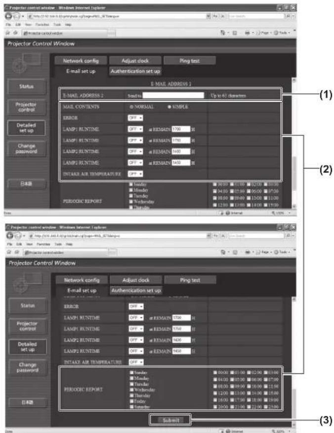
(1) [E-MAIL ADDRESS 2]
Enter the E-mail address to be sent when two E-mail addresses are to be used.
Leave it blank when two E-mail addresses are not to be used.
(2) Settings of the conditions to send E-mail
Select the conditions to send E-mail to the second E-mail address.
[MAIL CONTENTS]:
Select either [NORMAL] or [SIMPLE].
[ERROR]:
An E-mail message is sent when an error occurred in the self-diagnosis.
[LAMP1 RUNTIME]:
An E-mail message is sent when the remaining lamp on time for the lamp 1 has reached the value set at the right field.
[LAMP2 RUNTIME]:
An E-mail message is sent when the remaining lamp on time for the lamp 2 has reached the value set at the right field.
[INTAKE AIR TEMPERATURE]:
An E-mail message is sent when the air intake temperature has reached the value set at the above field.
[PERIODIC REPORT]:
Place a check mark on this when E-mail is to be sent periodically to the second E-mail address. It will be sent on the days and time with the check mark.
(3) [Submit]
Update the settings.
■[Authentication set up] page
You can set the authentication items when POP authentication or SMTP authentication is necessary to send an E-mail message.
Click [Detailed set up] → [Authentication set up].

(1) [Auth]
Select the authentication method specified by your Internet service provider.
(2) [SMTP Auth]
Set when the SMTP authentication is selected.
(3) [Pop Server name]
Enter the POP server name.
Allowed characters:
Alphanumerics (A - Z, a - z, 0 - 9)
Minus sign (-) and period (.)
(4) [User name]
Enter the user name for the POP server or the SMTP server.
(5) [Password]
Enter the password for the POP server or the SMTP server.
(6) [SMTP server port]
Enter the port number for the SMTP server.
(Normally 25)
(7) [POP server port]
Enter the port number for the POP server.
(Normally 110)
(8) [Submit]
Update the settings.
■ Contents of mail sent
●Example of E-mail sent when E-mail is set
The following E-mail is sent when the E-mail settings have been established.
| === Panasonic projector report(CONFIGURE) === |
| Projector Type : DX800 |
| Serial No : SH1234567 |
| ---- E-mail setup data ---- |
| TEMPERATURE WARNING SETUP |
| MINIMUM TIME at [ 60] minutes interval |
| INTAKE AIR TEMPERATURE Over [ 45C / 113F ] |
| ERROR [ OFF ] |
| LAMP1 RUNTIME [ OFF ] at REMAIN [ 400] H |
| LAMP1 RUNTIME [ OFF ] at REMAIN [ 200] H |
| LAMP2 RUNTIME [ OFF ] at REMAIN [ 400] H |
| LAMP2 RUNTIME [ OFF ] at REMAIN [ 200] H |
| INTAKE AIR TEMPERATURE [ OFF ] |
| PERIODIC REPORT |
| Sunday [ OFF ] Monday [ OFF ] Tuesday [ OFF ] Wednesday [ OFF ] |
| Thursday [ OFF ] Friday [ OFF ] Saturday [ OFF ] |
| 00:00 [ OFF ] 01:00 [ OFF ] 02:00 [ OFF ] 03:00 [ OFF ] |
| 04:00 [ OFF ] 05:00 [ OFF ] 06:00 [ OFF ] 07:00 [ OFF ] |
| 08:00 [ OFF ] 09:00 [ OFF ] 10:00 [ OFF ] 11:00 [ OFF ] |
| 12:00 [ OFF ] 13:00 [ OFF ] 14:00 [ OFF ] 15:00 [ OFF ] |
| 16:00 [ OFF ] 17:00 [ OFF ] 18:00 [ OFF ] 19:00 [ OFF ] |
| 20:00 [ OFF ] 21:00 [ OFF ] 22:00 [ OFF ] 23:00 [ OFF ] |
| ---- check system ---- |
| MAIN CPU BUS [ OK ] |
| FAN [ OK ] |
| INTAKE AIR TEMPERATURE [ OK ] |
| OPTICS MODULE TEMPERATURE [ OK ] |
| AROUND LAMP TEMPERATURE [ OK ] |
●Example of the E-mail sent for an error
The following E-mail is sent when an error has occurred.
| === Panasonic projector report(ERROR) === |
| Projector Type : DX800 |
| Serial No : SH1234567 |
| ---- check system ---- |
| MAIN CPU BUS | [ OK ] |
| FAN | [ OK ] |
| INTAKE AIR TEMPERATURE | [ OK ] |
| OPTICS MODULE TEMPERATURE | [ OK ] |
| AROUND LAMP TEMPERATURE | [ OK ] |
| LAMP1 REMAIN TIME | [ OK ] |
| LAMP2 REMAIN TIME | [ OK ] |
| LAMP1 STATUS | [ OK ] |
| LAMP2 STATUS | [ OK ] |
| SHUTTER | [ OK ] |
| INTAKE AIR TEMP.SENSOR | [ OK ] |
| OPTICS MODULE TEMP.SENSOR | [ OK ] |
| AROUND LAMP TEMP.SENSOR | [ OK ] |
| BATTERY | [ OK ] |
| AIRFLOW SENSOR | [ OK ] |
| COLOR WHEEL | [ OK ] |
| COVER OPEN | [ OK ] |
| FILTER UNIT | [ FAILED ] |
| AIR FILTER | [ OK ] |
| (Error code 04 00 00 00 00 00 00 00) |
| Intake air temperature : 27 degC / 80 degF |
| Optics module temperature : 33 degC / 91 degF |
| Around lamp temperature : 32 degC / 89 degF |
| PROJECTOR RUNTIME 0 H |
| POWER ON 0 times |
| LAMP1 ON 0 times |
| LAMP1 LOW 0 H |
| LAMP1 HIGH 0 H |
| LAMP1 REMAIN 2000 H |
| LAMP2 ON 0 times |
| LAMP2 LOW 0 H |
| LAMP2 HIGH 0 H |
| LAMP2 REMAIN 2000 H |
| ---- Current status ---- |
| MAIN VERSION 1.00 |
| NETWORK VERSION 1.00 |
■[Change password] page
Click [Change password].

• [Administrator] account
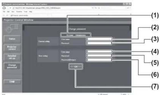
- [User] account
![PANASONIC PT-DW730U - ■[Change password] page - 3](/content/2026/06/1201863/images/2059d2f5382baec3920e1074b678792ee1e0291644ee49bd59925a855555a4d6.jpg)
● [Change password] (when accessed by user rights)
Only the change of password is enabled under the user rights.

(1) [Administrator]
Select this when you change the [Administrator] setting.
(2) [User]
Select this when the [User] setting.
(3) [Next]
Displays the screen to change the password setting.
(1) [Account]
Displays the account to change.
(2) [Current setting] [User name]
Enter the user name before the change.
(3) [Current setting] [Password]
Enter the current password.
(4) [New setting] [User name]
Enter the desired new user name.
(5) [New setting] [Password]
Enter the desired new password.
(6) [New setting] [Password (Retype)]
Enter the desired new password again.
(7) [OK]
Determines the change of password.
(1) [Account]
Displays the account to change.
(2) [New setting] [User name]
Enter the desired new user name.
(3) [New setting] [Password]
Enter the desired new password.
(4) [New setting] [Password (Retype)]
Enter the desired new password again.
(5) [OK]
Determines the change of password.
Note
- To change the account of the administrator, it is required to enter [User name] and [Password] in [Current setting].
LAMP/TEMP/FILTER Indicators
Managing the indicated problems
If a problem should occur inside the projector, the lamp indicators /, the temperature indicator , and the filter indicator will inform you.
Manage the indicated problems as follow.
Attention
- Before you take a remedial measure, follow the procedure of switching the power off indicated in “Powering off the projector” (→ page 35).
- Check the power status with the power indicator (→ page 33).

Lamp indicator /
| Lamp indication | Lighting in red | Blinking in red (once) | Blinking in red (3 times) |
| Status | Indicates the time to replace the lamp unit. | The lamp unit is not installed. | A problem is detected in the lamp or the power supply for the lamp. |
| Points to be checked | ● Is [REPLACE LAMP] displayed when you turned on the power? | ● Is the lamp unit installed? | ● Did you turn on the power again immediately after turning it off? | ● Some error has arisen in the lamp circuit. Check for fluctuation (or drop) in the source voltage. |
| Remedial measure | ● This indicator lights up when the lamp unit usage has reached 1 800 hours (when [LAMP POWER] is set to [HIGH]).● Replace the lamp unit. | ● Install the lamp unit.● If the indicator is still blinking in red despite having installed a lamp unit, consult your dealer. | ● Wait until the lamp has cooled off before turning on the power. | ● Set theswitch to(→ page 35), and consult your dealer. |
Note
- If the lamp indicators / are still lighting or blinking after taking the preceding measures, ask your dealer to repair the unit.
LAMP/TEMP/FILTER Indicators
■Temperature indicator
| Lamp indication | Lighting in red | Blinking in red (once) | Blinking in red (3 times) |
| Status Warm-up status | Internal temperature is high. (WARNING) | Internal temperature is high. (Standby condition) | The cooling fan has been stopped. |
| Points to be checked | Did you turn on the power when the ambient temperature was lower than approx. 0°C (32°F)? | Is the ventilating port (intake/exhaust) blocked?Is the room temperature too high?Is the filter indicatorlit? | — |
| Remedial measure | Wait about five minutes in the current status.Install the unit in a location with an ambient temperature from 0°C (32°F) - 45°C (113°F)*1. | Remove any objects that are blocking the ventilating port (intake/exhaust).Move the projector to a temperature of 0°C (32°F) - 45°C (113°F)*1 and the humidity of 20% to 80% (no condensation). | Set theswitch to(→ page 35), and consult your dealer. |
*1: When using the projector at high elevations 1 400 m (4 593 ft) – 2 700 m (8 858 ft) sea level, the temperature will be 5°C (41°F) lower than this higher limit.
Note
- If the temperature indicator is still lighting or blinking after taking the preceding measures, ask your dealer to repair the unit.
- If the projector is used with the following two settings when the ambient temperature reaches 40^ (104°F) (35°C (95°F) in [HIGH ALTITUDE MODE]) or above, the light output may decrease by 20% to protect the projector.
– [LAMP SELECT] is set to [DUAL] in the menu
– [LAMP POWER] is set to [HIGH] in the menu
■Filter indicator
| Lamp indication | Lighting in red Blinking in red | |
| Status | The filter is clogged.The ambient temperature or the internal temperature is extremely high. | The air filter unit is not attached. |
| Points to be checked | ● Is the air filter unit dirt? | ● Is the ventilating port (intake/exhaust) blocked? | ● Is [HIGH ALTITUDE MODE] set correctly? | ● Is the air filter unit attached? |
| Remedial measure | ● Clean the air filter unit. (→ page 89) | ● Remove any objects that are blocking the ventilating port (intake/exhaust). | ● When using the projector at high elevations 1 400 m (4 593 ft) – 2 700 m (8 858 ft) sea level, set [HIGH ALTITUDE MODE] (→ page 61) to [ON].● Do not use the projector at high elevations 2 700 m (8 858 ft) or higher sea level. | ● Attach the air filter unit. |
Note
- If the filter indicator is still lighting or blinking after taking the preceding measures, ask your dealer to repair the unit.
- If the air filter unit is not attached when the power is turned on, the filter indicator will blink in red and the power will turn off after ten minutes.
- If the filter is clogged, only one lamp may light even when [LAMP SELECT] is set to [DUAL]. Clean the air filter unit or replace with new one.
Maintenance/Replacement
Before maintaining/replacing the unit
● Make sure to turn off the power before maintaining or replacing the unit. (→ pages 32, 35)
- When turning off the power, make sure to follow the procedures in "Powering off the projector" (→ page 35).
Maintenance
Outer case
Wipe off dirt and dust with a soft, dry cloth.
- If the dirt is persistent, soak the cloth with water and wring it thoroughly before wiping. Dry off the projector with a dry cloth.
- Do not use benzene, thinner, or rubbing alcohol, other solvents, or household cleaners. Using them may cause deterioration of the outer case.
- When using chemical treated dusters, follow the instructions.
■Front surface of the lens
Wipe off dirt and dust off the front surface of the lens with a soft clean cloth.
- Do not use a cloth that is fluffy, dusty, or soaked with oil/water.
- Do not use excessive force when wiping the lens as it is fragile.
Attention
- Impacts or excessive force when wiping may scratch its surface. Please handle with care.
Air filter unit
Perform maintenance of the air filter unit in the following cases.
- The air filter is clogged with dust, causing the filter replacement message to appear on the screen and the filter indicator to light in red.
1) Remove the air filter cover.
- Use a Phillips screw driver to turn the air filter cover screw (one screw) counterclockwise until it turns freely, and then remove the air filter cover.

2) Pull out the air filter unit.
- Hold the tabs on the air filter unit and pull out the air filter unit from the projector.
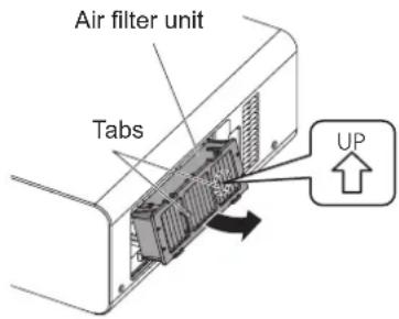
3) Clean and dry the air filter unit.
- Cleaning the air filter unit
(a) Soak the air filter unit in cold or warm water and then lightly rinse it.
- Do not use cleaning tools such as brushes.
- When rinsing, hold the frame of the air filter unit without putting strong pressure on the filter unit.
(b) Rinse the unit two to three times using fresh water each time.
- Insufficient rinsing may result in odors.
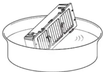
natural_image
Technical line drawing of a mechanical component inside a circular container (no text or symbols)
● Drying the air filter unit
- Let the unit naturally dry off in a well-ventilated place where there is little dust and the unit is protected from direct sunlight.
- Do not dry using drying devices such as dryers.

Maintenance/Replacement
4) Attach the air filter unit to the projector.
- The air filter unit has vertical distinctions. (Check the direction of the allow 📤.)
● Perform Step 2) in the reverse order.
5) Attach the air filter cover to the projector and use a Phillips screwdriver to tighten the air filter cover screw.
● Perform Step 1) in the reverse order.
Attention
● After washing the air filter unit, dry it thoroughly before attaching it back to the projector. Attaching a wet unit will cause an electric shock or malfunction.
- Do not disassemble the air filter unit.
Note
- Make sure that the air filter is properly attached before using the projector. If it is not properly installed, the projector will suck in dirt and dust causing a malfunction which turns the power off after ten minutes. (The time remaining before the power is turned off is displayed in one minute intervals.)
- Replace the air filter unit with a replacement filter unit (ET-EMF300) if it is damaged or if the dirt does not come off even after washing.
● Air filter replacement is recommended after cleaning the unit two times.
- The dust-proof properties may reduce after each cleaning.
Replacing the unit
Air filter unit
If dirt does not come off even if the unit is maintained, it is time for the unit to be replaced. The replacement filter unit (ET-EMF300) is sold separately. To purchase the product, consult your dealer.
■Replacement of the air filter unit
Attention
● Make sure to turn off the power before replacing the air filter unit.
- When replacing the unit, make sure that the projector is stable. Perform the replacement in a safe place where the projector will not be damaged even if you drop the air filter unit.
1) Remove the air filter cover.
- Use a Phillips screw driver to turn the air filter cover screw (one screw) counterclockwise until it turns freely, and then remove the air filter cover.
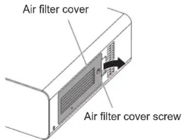
2) Pull out the air filter unit.
- Hold the tabs on the air filter unit and pull out the air filter unit from the projector.

- After removing the air filter unit, remove large foreign objects and dust from the air filter unit and the projector's air intake port if there are any.
3) Attach the separately sold replacement filter unit (ET-EMF300) to the projector.
- The air filter unit has vertical distinctions. (Check the direction of the allow .)
● Perform Step 2) in the reverse order.
4) Attach the air filter cover to the projector. Using a Phillips screwdriver, tighten the air filter cover screw.
● Perform Step 1) in the reverse order.
Attention
- When turning the projector on, make sure that the air filter unit is installed before using the projector. If it is not properly installed, the projector will suck in dirt and dust causing a malfunction which turns the power off after ten minutes. (The time remaining before the power is turned off is displayed in one minute intervals.)
Note
● The replacement cycle of the air filter unit varies greatly depending on the usage environment.
Lamp unit
The lamp unit is a consumable component. Check the usage duration in the [PROJECTOR SETUP] menu → [STATUS] (→ page 64) and perform regular replacement.
It is recommended that you request a qualified technician to replace the lamp unit. Consult your dealer.
Consult your dealer to purchase a replacement lamp unit (ET-LAD60A: 1 pc, ET-LAD60AW: 2 pcs).
Attention
- Do not replace the lamp unit when it is hot. (Wait at least one hour after use.)
The inside of the cover can become very hot, take care to avoid burn injuries.
■Notes on the replacement of the lamp unit
- Since the luminous lamp is made of glass, it may burst if dropped or hit with a hard object. Please handle with care.
● A Phillips screwdriver is necessary when replacing the lamp unit.
- When replacing the lamp unit, be sure to hold it by the handle.
- The lamp may burst. Replace the lamp unit carefully so that the broken pieces of the lamp glass will not scatter. When the projector is mounted on the ceiling, do not make the replacement directly under the lamp unit or put your face near it.
- The lamp contains mercury. When disposing of used lamps, ask your nearest ward office or dealer about proper disposal of the unit.
Attention
● Use only specified lamp units.
● The part numbers of accessories and separately sold components are subject to change without notice.
■When to replace the lamp unit
The lamp unit is a consumable component. Since its brightness gradually decreases over time, it is necessary to replace it regularly. The estimated duration before replacement is 2 000 hours. However, this may be shortened depending on individual lamp characteristics, usage conditions, and the installation environment. Therefore, it is strongly recommended that a replacement lamp unit be kept. The unit can damage the projector if it has not been replaced after 2 000 hours of usage. Thus, the lamp automatically turns off after approximately ten minutes.
| On screen Lamp indicatorREPLACE LAMP |  |
| Over 1 800 hours | The message is displayed for 30 seconds. Pressing any button on the control panel or remote control within 30 seconds will clear the message. | Lights in red even during the standby mode. (only the corresponding lamp lights up) |
| Over 2 000 hours | The message remains displayed until you press any button. |
Note
● 2 000 hours of use is a rough guideline, but this is not a guarantee.
Maintenance/Replacement
■Replacing the lamp unit
Attention
- When the projector is mounted on the ceiling, do not put your face near the lamp unit.
- Securely attach the lamp unit and lamp unit cover.
- If the lamp unit is not installed properly, remove it and then install it again. Pushing it in forcibly may break the connector.
1) Follow the procedures described in "Powering off the projector"→(page 35) to set the switch to , disconnect the power plug from the power outlet, and wait at least one hour, and then check if the lamp unit has cooled down.
2) Remove the lamp unit cover.
(a) Use a Phillips screwdriver to loosen the lamp unit cover fixing screw (one screw) until it turns freely, and then open the lamp unit cover in the direction of the arrow.
(b) Hold the lamp unit firmly, slide it towards the control buttons, then pull it out.

3) Use a Phillips screw driver to remove the lamp unit fixing screws (three screws each), and then holding the handles, pull out the lamp unit from the projector.

4) Carefully push the new lamp unit into the projector.
5) Use a Phillips screw driver to tighten the lamp unit fixing screws (three screws each).
6) Attach the lamp unit cover.
(a) Attach the lamp unit cover by aligning the (i) and (ii) symbols (○ and △
(b) After sliding the lamp unit cover in the direction of the arrow and inserting it forward, securely tighten the lamp unit cover fixing screw.
● Make sure that the lamp unit cover connector is firmly inserted into the fan power connector.

Note
- When you replace the new lamp unit, the projector resets the total usage time of the lamp unit automatically.
Troubleshooting
Review the following points. For details, see the corresponding pages.
| Problems Points to be checked | Reference page |
| Power does not turn on. | Is the power plug firmly inserted into the outlet?Is theswitch turned? 35Does the outlet in which the power plug is inserted have a supply of electricity?Have the circuit breakers tripped? —Is the temperature indicatoror the lamp indicators/lit or blinking?Is the lamp unit cover securely installed? 9 | —87, 882 |
| No picture appears. | Is the connection to the picture (output) device correct? 30Is the input selection setting correct? 38Is the [BRIGHTNESS] adjustment setting at a minimum? 44Is the external device that is connected to the projector working properly?Is the shutter function in use? 38 | — |
| The picture is fuzzy. | Has the lens focus been set correctly? 36Is the projection distance appropriate? 2Is the lens dirty? 15Is the projector installed perpendicular to the screen? | 2— |
| The color is pale or grayish. | Are the [COLOR] and [TINT] adjusted correctly? 45Is the device connected to the projector adjusted correctly?Is the RGB cable damaged? | 30— |
| The remote control does not operate. | Are the batteries depleted?Is the polarity of the batteries set correctly?Are there any obstructions between the remote control and the projector's remote control signal receiver?Is the remote control being used beyond its effective operation range?Are other forms of light, such as fluorescent lights, affecting the projection?Is the [REMOTE CONTROLLER] setting in [CONTROL DEVICE SETUP] set to [DISABLE]?Is theterminal used for external control?Is the ID number setting correct? | —201717177110020 |
| On screen menu does not appear. | Is the on-screen display function turned off (hidden)? | 19, 38 |
| The control buttons of the projector do not operate. | Is the [CONTROL PANEL] setting in [CONTROL DEVICE SETUP] set to [DISABLE]?Is theterminal used for external control? | 71100 |
| The picture does not display correctly. | Is the [SYSTEM SELECTOR] selection set correctly?Is there a problem with the VCR or other picture sources?Is the projector getting signals that it does not support? | 47—102 |
Troubleshooting
| Problems Points to be checked | Reference page |
| Picture from a computer does not appear. | ● Is the cable too long? (Use a cable that is 10 m or shorter.) —● Is the external video output of the laptop computer set correctly? (Example: The external output settings may switch by pressing the [Fn] + [F3] or [Fn] + [F10] key simultaneously. Since the method varies depending on the computer type, refer to the user manual provided with your computer.) | — |
| Picture from a computer's DVI-D graphic board does not appear. | ● Is the [DVI-D IN] setting set to [EDID3]/[EDID2:PC]? 58● The graphics accelerator driver of the computer may need to be updated to the latest version.● The computer may need to be restarted after performing [DVI-D IN] settings. | —58 |
Attention
- If problems persist even after checking the preceding points, consult your dealer.
PJLink protocol
The network function of this projector supports the PJLink class 1, and the PJLink protocol can be used to perform projector setting and projector status query operations from a computer.
Control commands
The following table lists the PJLink protocol commands that can be used to control the projector.
| Command | Control details Notes | |
| POWR Power supply control | Parameters0 = Standby1 = Power ON |
| POWR? Power supply status query | Parameters0 = Standby 1 = Power ON2 = Cool-down in progress 3 = Warm-up in progress |
| INPT Input selection | Parameters11=RGB1 12=RGB2 21=VIDEO22=S-VIDEO 31=DVI-D |
| INPT? Input selection query |
| AVMT Shutter control Parameters | 30 = SHUTTER function off (picture mute canceled)31 = SHUTTER function on (picture mute) |
| AVMT? Shutter status query |
| ERST? Error status query | Parameters1st byte: Indicates fan errors, range 0 - 22nd byte: Indicates lamp errors, range 0 - 23rd byte: Indicates temperature errors, range 0 - 24th byte: Indicates cover open errors, range 0 - 25th byte: Indicates filter errors, range 0 - 26th byte: Indicates other errors, range 0 - 2Definitions for each value from 0 to 2 are as follows0 = No error detected 1 = Warning 2 = Error |
| LAMP? | Lamp status query | Parameters1st digits (1 - 5 digits): Lamp 1 cumulative operating time2nd digit: 0 = Lamp 1 off, 1 = Lamp 1 on3rd digits (1 - 5 digits): Lamp 2 cumulative operating time4th digit: 0 = Lamp 2 off, 1 = Lamp 2 on |
| INST? Input | selection list query | Parameters are returned with the following values.“11 12 21 22 31” |
| NAME? | Projector name query | Returns the name set in [PROJECTOR NAME] of [NETWORK SETUP]. |
| INF1? Manufacturer name query Returns “Panasonic”. |
| INF2? Model name query Returns “DX800U” “DW730U”. |
| INF0? | Other information query | Returns information such as version number. |
| CLSS? Class information query Returns “1”. |
■PJLink security authentication
The password used for PJLink is the same as that of the password set for web browser control.
When using PJLink without security authentication, do not set a password for web browser control.
- For specifications regarding PJLink, refer to the Japan Business Machine and Information System Industries Association website.
URL http://pjlink.jbmia.or.jp/english/
Control commands via LAN
■When WEB Control administrator rights password is set (Protect mode)
- Connection method
1) Obtain the IP address and port number (Initial set value = 1024) of the projector and request for a connection to the projector.
You can obtain both the IP address and the port number from the menu screen of the projector.
| IP address Obtain from MAIN MENU → [NETWORK] → [NETWORK STATUS] |
| Port No. | Obtain from MAIN MENU → [NETWORK] → [NETWORK CONTROL] → [COMMAND PORT] |
2) Check the projector's response.
Response data
| Data section Blank | Mode Blank | Random number section | Termination symbol |
| “NTCONTROL” (ASCII string) | 0x20 | 0x31 | 0x20 | “(ASCII code hexadecimal number) | (CR) 0x0d |
| 9 bytes 1 byte 1 | byte 1 byte 8 | bytes 1 byte | | | |
Mode: 1 = Protect mode
3) Generate a 32-byte hash value from the following data using MD5 algorithm.
"xxxxxx:yyyy:zzzzzzzzz"
| xxxxxx | Administrator rights user name for WEB CONTROL (default user name is “admin1”). |
| yyyyy | Password of above administrator rights user (default password is “panasonic”). |
| zzzzzzzzz 8-byte | random number obtained in Step 2) |
●Command transmission method
Transmit using the following command formats.
Transmitted data
| Header | Data section | Termination symbol |
| Hash value(See above “Connection method”) | ‘0’0x30 | ‘0’0x30 | Control command(ASCII string) | (CR)0x0d |
| 32 bytes | 1 byte | 1 byte | Undefined length | 1 byte |
Received data
| Header | Data section | Termination symbol |
| ‘0’0x301 byte | ‘0’0x301 byte | Control command(ASCII string)Undefined length | (CR)0x0d1 byte |
Error response
| Error message | Termination symbol |
| “ERR1” | Undefined control command | |
| “ERR2” | Out of parameter range | |
| “ERR3” | Busy state or no-acceptable period | (CR) |
| “ERR4” | Timeout or no-acceptable period | 0x0d |
| “ERR5” | Wrong data length | |
| “ERRA” | Password mismatch | |
| 4 bytes | 1 byte |
■ When WEB Control administrator rights password is not set (Non-protect mode)
- Connection method
1) Obtain the IP address and port number (Initial set value = 1024) of the projector and request for a connection to the projector.
You can obtain both the IP address and the port number from the menu screen of the projector.
| IP address Obtain from MAIN MENU → [NETWORK] → [NETWORK STATUS] |
| Port No. | Obtain from MAIN MENU → [NETWORK] → [NETWORK CONTROL] → [COMMAND PORT] |
2) Check the projector's response
Response data
| Data section Blank Mode | | | Termination symbol |
| “NTCONTROL”(ASCII string) | ‘’0x20 | ‘0’0x30 | (CR)0x0d |
| 9 bytes 1 byte 1 byte 1 byte |
Mode: 0 = Non-protect mode
●Command transmission method
Transmit using the following command formats.
Transmitted data
| Header Data section | | Termination symbol |
| ‘0’0x301 byte 1 byte Undefined length 1 byte | ‘0’0x30 | Control command(ASCII string) | (CR)0x0d |
Received data
| Header Data section | | Termination symbol |
| '0'0x30 | '0'0x30 | Control command(ASCII string) | (CR)0x0d |
| 1 byte | 1 byte Undefined | length 1 byte | |
Error response
| Error message | Termination symbol |
| “ERR1” | Undefined control command | |
| “ERR2” | Out of parameter range | |
| “ERR3” | Busy state or no-acceptable period | (CR) |
| “ERR4” | Timeout or no-acceptable period | 0x0d |
| “ERR5” | Wrong data length | |
| “ERRA” | Password mismatch | |
| 4 bytes | 1 byte |
Serial terminal
The / terminals on the side of the projector conform with RS-232C so that the projector can be connected to and controlled from a computer.
■Connection
● Single projector Multiple projectors

flowchart
graph LR
    A["<Connecting terminals on projector>"] --> B["D-Sub 9-pin (female)"]
    A --> C["D-Sub 9-pin (male)"]
    B --> D["Computer Computer"]
    C --> D
    D --> E["<Connecting terminals on projector 1>"]
    E --> F["D-Sub 9-pin (female)"]
    E --> G["D-Sub 9-pin (male)"]
    F --> H["D-Sub 9-pin (female)"]
    G --> I["D-Sub 9-pin (male)"]
    H --> J["<Connecting terminals on projector 2>"]
    I --> J
Communication cable Communication cable Communication cable
■Pin assignments and signal names
D-Sub 9-pin (female) Outside view  | Pin No. Signal name Details | |
| (1) – NC | | |
| (2) TXD Transmitted data | |
| (3) RXD Received data | |
| (4) – Connected internally | |
| (5) | GND | Earth |
| (6) – NC | | |
| (7) CTS | | Connected internally |
| (8) RTS | |
| (9) – NC | | |
D-Sub 9-pin (male)
Outside view

■Communication conditions (Factory default settings)
| Signal level | RS-232C-compliant |
| Sync. method | Asynchronous |
| Baud rate | 9 600 bps |
| Parity | None |
| Character length 8 bits |
| Stop bit | 1 bit |
| X parameter | None |
| S parameter | None |
Transmission from the computer starts with STX, then the ID, command, parameter, and ETX are sent in this order. Add parameters according to the details of control.

Attention
- When a command is transmitted after the lamp turned on, there may be a delay in response or the command may not be executed. Try sending any command after 60 seconds.
- When transmitting multiple commands, be sure to wait until 0.5 seconds has elapsed after receiving the response from the projector before sending the next command. When transmitting a command which does not need a parameter, a colon (:) is not necessary.
Note
- If a command cannot be executed, a "ER401" response is sent from the projector to the computer.
- If an invalid parameter is sent, a "ER402" response is sent from the projector to the computer.
- ID transmission in RS-232C supports ZZ (ALL) and the 01 to 64 and 0A to 0Z groups.
- If a command is sent with a specified ID, a response will be sent to the computer only in the following cases.
– It matches the projector ID
– ID setting is set to ALL and responding (ID ALL) is [ON]
– ID setting is set to Group and responding (ID Group) is [ON]
- STX and ETX are character codes. STX shown in hexadecimal is 02, and ETX shown in hexadecimal is 03.
Cable specifications

Control commands
The following table lists the commands that can be used to control the projector using a computer.
| Command | Details Notes | (Parameter) |
| PON POWER ON | To check if the power is on, use the “Power query” command. |
| POF STANDBY |
| QPW | Power query | 000 = Standby 001 = POWER ON |
| IIS Switch input modes | VID = VIDEO SVD = S-VIDEO RG1 = RGB1RG2 = RGB2 DVI = DVI-D |
| QSL | Query for active lamp selection | 0 = DUAL 1 = SINGLE ^1 2 = LAMP1 3 = LAMP2 |
| LPM Lamp mode | 0 | DUAL 1 = SINGLE ^1 2 = Only LAMP1 is ON 3 = Only LAMP2 is ON |
| OLP Lamp power setting | 0 | = HIGH 1 = LOW |
*1: Uses the lamp (LAMP1 or LAMP2) with shorter operating hours.
REMOTE 2 IN terminal
It is possible to control the projector remotely (by external contact) from a control panel located away from the projector where remote control signals cannot reach. Use the terminal on the side of the projector to connect to the control panel.

flowchart
graph TD
    A["Remote control External control"] --> B["Standby ON"]
    B --> C["LAMP"]
    C --> D["RGB1 VIDEO"]
    C --> E["RGB2 S-VIDEO"]
    C --> F["DVI-D"]
Projector set up in a meeting room Control panel located in a different room
■Pin assignments and signal names
| D-Sub 9-pin (Outside view) Pin No. Signal name Open (H) Short (L) |
 | (1) GND | - | GND |
| (2) | POWER | OFF |
| (3) | RGB1 | Other |
| (4) | RGB2 | Other |
| (5) | VIDEO | Other |
| (6) | S-VIDEO | Other |
| (7) | DVI-D | Other |
| (8) | SHUTTER | OFF |
| (9) | RST/SET | Controlled by remote control |
Attention
- When controlling, make sure to short-circuit pins (1) and (9).
- When pins (1) and (9) are short-circuited, the following buttons on the control panel and the remote control cannot be used.
The POWER ON < | > button, the STANDBY < ⏻> button, the button, and the corresponding RS-232C commands and network functions cannot be used either.
- When pins (1) and (9) are short-circuited, do not short-circuit any pins from (3) to (7) with pin (1). The following buttons on the control panel and the remote control cannot be used.
The POWER ON < | > button, the STANDBY < ◀> button, the button, the button, the button, the
Note
- For pin (2) to pin (8) settings, you can make changes if you set [REMOTE2 MODE] to [USER]. (→ page 64)
Two window display combination list (PT-DW730U only)
| Input AInput B | RGB1Stillimage | RGB1Movie | RGB2Stillimage | RGB2Movie | VIDEO S | VIDEO | DVI Stillimage | DVI Movie |
| RGB1Still image | --√√ | √√√√ | | | | | | |
| RGB1Movie | --√-- | --√- | | | | | | |
| RGB2Still image | √√-- | √√√√ | | | | | | |
| RGB2Movie | √---- | --√- | | | | | | |
| VIDEO | √ | - | √ | - | - | - | √ | - |
| S-VIDEO | √ | - | √ | - | - | - | √ | - |
| DVIStill image | √√√√ | √√-- | | | | | | |
| DVIMovie | √-√---- | | | | | | | |
√: Two window display combination is possible
-: Two window display combination is not possible
Signals that are treated as "movies":
480i, 576i, 480p, 576p, 1080/60i, 1080/50i, 1080/60p,
1080/50p, 1080/24sF, 1080/30p, 1080/25p, 1080/24p,
720/60p, 720/50p, NTSC, PAL, SECAM, NTSC4.43, PAL-M, PAL-N, PAL60
To initialize your password, consult your distributor.
List of compatible signals
The following table specifies the types of signals compatible with the projectors.
| Mode | Resolution(Dots) | Scanning frequency | Dotclockfrequency(MHz) | Picturequality ^3 | Plug and play ^6 | Format ^7 |
| Horizontal(kHz) | Vertical(Hz) | RGB2 | DVI-DEDID1 | DVI-DEDID2 |
| NTSC/NTSC4.43/PAL-M/PAL60 | 720 x 480i 15.7 | 59.9 | | — | A | — — | — | | V/S |
| PAL/PAL-N/SECAM | 720 x 576i | 15.6 | 50.0 | — | A | — — | — | | V/S |
| 525i(480i) | 720 x 480i | 15.7 | 59.9 | 13.5 | A | — — | — | | R/Y |
| 625i(576i) | 720 x 576i | 15.6 | 50.0 | 13.5 | A | — — | — | | R/Y |
| 525p(480p) 720 x 483 | 31.5 59.9 27.0 A | | | | | — √— | | | D/R/Y |
| 625p(576p) | 720 x 576 | 31.3 | 50.0 | 27.0 | A | — √— | | | D/R/Y |
| 1125(1080)/601 ^1 | 1 920 x 1 080i 33.8 | 60.0 74.3 A | | | | — √— | | | D/R/Y |
| 1125(1080)/50i | 1 920 x 1 080i | 28.1 | 50.0 | 74.3 | A | — √— | | | D/R/Y |
| 1125(1080)/24p | 1 920 x 1 080 | 27.0 | 24.0 | 74.3 | A | — √— | | | D/R/Y |
| 1125(1080)/24sF | 1 920 x 1 080i 27.0 | 24.0 74.3 A | | | | — — | — | | D/R/Y |
| 1125(1080)/25p | 1 920 x 1 080 | 28.1 | 25.0 | 74.3 | A | — √— | | | D/R/Y |
| 1125(1080)/30p | 1 920 x 1 080 | 33.8 | 30.0 | 74.3 | A | — — | — | | D/R/Y |
| 1125(1080)/60p | 1 920 x 1 080 | 67.5 | 60.0 | 148.5 | A | — √— | | | D/R/Y |
| 1125(1080)/50p | 1 920 x 1 080 | 56.3 | 50.0 | 148.5 | A | — √— | | | D/R/Y |
| 750 (720)/60p | 1 280 x 720 45.0 | 60.0 74.3 AA | | | ^* 4 | — √— | | | D/R/Y |
| 750 (720)/50p | 1 280 x 720 37.5 | 50.0 74.3 AA | | | ^* 4 | — √— | | | D/R/Y |
| VGA400 | 640 x 400 31.5 | 70.1 25.2 A | | | | — — | — | | D/R |
| 640 x 400 37.9 | 85.1 31.5 A | | | | — — | — | | D/R |
| VGA480 | 640 x 480 31.5 | 59.9 25.2 A | | | | √ | √ | √ | D/R |
| 640 x 480 35.0 | 66.7 30.2 A | | | | — — | — | | D/R |
| 640 x 480 37.9 | 72.8 31.5 A | | | | √— | √ | | D/R |
| 640 x 480 | 37.5 | 75.0 | 31.5 | A | √— | √ | | D/R |
| 640 x 480 43.3 | 85.0 36.0 A | | | | — — | — | | D/R |
| SVGA | 800 x 600 | 35.2 | 56.3 | 36.0 | A | √— | √ | | D/R |
| 800 x 600 37.9 | 60.3 40.0 A | | | | √— | √ | | D/R |
| 800 x 600 48.1 | 72.2 50.0 A | | | | √— | √ | | D/R |
| 800 x 600 | 46.9 | 75.0 | 56.3 A | | √— | √ | | D/R |
| 800 x 600 | 53.7 | 85.1 | 56.3 | A | — — | — | | D/R |
| MAC16 | 832 x 624 | 49.7 | 74.6 | 57.3 | A | √— | √ | | D/R |
| XGA | 1 024 x 768 39.6 | 50.0 51.9 AA | | | ^* 5 | — — | — | | D/R |
| 1 024 x 768 48.4 | 60.0 65.0 AA | | | ^* 5 | √— | √ | | D/R |
| 1 024 x 768 | 56.5 | 70.1 | 75.0 | AA ^* 5 | √— | √ | | D/R |
| 1 024 x 768 60.0 | 75.0 78.8 AA | | | ^* 5 | √— | √ | | D/R |
| 1 024 x 768 | 65.5 | 81.6 | 86.0 | AA ^* 5 | — — | — | | D/R |
| 1 024 x 768 | 68.7 | 85.0 | 94.5 | AA ^* 5 | — — | — | | D/R |
| 1 024 x 768 | 80.0 | 100.0 | 105.0 | AA ^* 5 | — — | — | | D/R |
| 1 024 x 768 | 96.7 | 120.0 | 130.0 | AA ^* 5 | — — | — | | D/R |
| Mode | Resolution(Dots) | Scanning frequency | Dotclockfrequency(MHz) | Picturequality*3 | Plug and play*6 | Format*7 |
| Horizontal(kHz) | Vertical(Hz) | RGB2 | DVI-DEDID1 | DVI-DEDID2 |
| MXGA | 1 152 x 864 64.0 | 71.2 94.2 | A | | | — — | — | | D/R |
| 1 152 x 864 | 67.5 | 74.9 | 108.0 | A | — — | — | | D/R |
| 1 152 x 864 | 76.7 | 85.0 | 121.5 | A | — — | — | | D/R |
| MAC21 1 | 152 x 870 68.7 | 75.1 100.0 | A | | | √— | √ | | D/R |
| 1280 x 768 | 1 280 x 768 39.6 | 49.9 65.3 | AA | | *4 | — — | — | | D/R |
| 1 280 x 768 47.8 | 59.9 79.5 | AA | | *4 | — — | — | | D/R |
| 1280 x 800 | 1 280 x 800 41.3 | 50.0 68.0 | AA | | *4 | — — | — | | D/R |
| 1 280 x 800 49.7 | 59.8 83.5 | AA | | *4 | — — | — | | D/R |
| MSXGA 1 | 280 x 960 60.0 | 60.0 108.0 | A | | | — — | — | | D/R |
| SXGA | 1 280 x 1 024 64.0 | 60.0 108.0 | A | | | √— | √ | | D/R |
| 1 280 x 1 024 80.0 | 75.0 135.0 | A | | | √— | √ | | D/R |
| 1 280 x 1 024 91.1 | 85.0 157.5 | B | | | — — | — | | D/R |
| SXGA+ | 1 400 x 1 050 | 65.2 | 60.0 | 122.6 | A | √— | √ | | D/R |
| 1 400 x 1 050 82.2 | 75.0 155.9 | B | | | — — | — | | D/R |
| WXGA+ 1 | 440 x 900 | 55.9 | 59.9 | 106.5 | A | — — | — | | D/R |
| UXGA 1 | 600 x 1 200 75.0 | 60.0 162.0 | B | | | √— | √ | | D/R |
| WSXGA+ 1 | 680 x 1 050 | 65.3 | 60.0 | 146.3 | A | — — | — | | D/R |
| 1920 × 1080^*2 | 1 920 x 1 080 66.6 | 59.9 138.5 | A | | | — — | — | | D/R |
| WUXGA*2 | 1 920 x 1 200 74.0 | 60.0 154.0 | B | | | √— | √ | | D/R |
*1: When the 1035/60i signal is input, the signal is displayed as 1080/60i.
*2: VESA CVT-RB (Reduced Blanking) compatible
*3: Signals that show display picture quality are as follows.
AA : Projects the image in the highest picture quality.
A : Converts the image in the image processing circuit and projects the image.
B : Samples the image in the image processing circuit and projects the image.
*4: Signal A for PT-DX800U.
*5: Signal A for PT-DW730U.
*6: Signals with a √ in Plug and play are signals described in the projector's EDID (extended display identification data). If a signal has no √ in Plug and play but has an entry in the Format column, it can be entered. For signals without a √ in Plug and play, there are instances that resolution cannot be selected even though the computer supports them.
*7: Signals that show formats are as follows.
V: Video
S: S-Video
D: DVI-D
R: RGB
Y: YP_BP_R
Note
- The number of display dots is 1 280 x 800 for the PT-DW730U and 1 024 x 768 for the PT-DX800U. A signal with a different resolution will be projected after converting the resolution to match the projector display.
- The "i" at the end of the resolution indicates an interlaced signal.
- When interlaced signals are connected, flicker may occur on the projected image.
Specifications
The following table describes the specifications of the projector.
| Model No. PT-DW730U PT-DW730UL PT-DX800U PT-DX800UL | | |
| Power supply AC 120 V 50 Hz/60 Hz |
| Power consumption | 790 W |
| (When [STANDBY MODE] is set to [ECO]: 0.2 WWhen [STANDBY MODE] is set to [NORMAL]: 8 W) |
| Amps 7.5 A | |
| DLP chip | Size | 0.65" (aspect ratio 16:10) | 0.7" (aspect ratio 4:3) |
| Display system One-unit DLP chip, DLP type |
| Number of pixels | 1 024 000 pixels(1 280 x 800 dots) | 786 432 pixels(1 024 x 768 dots) |
| Lens | Power zoom 1.8 | to 2.5:1 | Optional | 1.8 to 2.5:1 | Optional |
| Power focus | F = 1.7 to 1.9f = 25.6 mmto 35.7 mm | F = 1.7 to 1.9f = 25.6 mmto 35.7 mm |
| Luminous lamp 300 W (maximum of 310 W) UHM lamp x 2 |
| Light output 7 000 lm | ''1 (ANSI) 8 000 lm | ''1 (ANSI) |
| Applicable scanning frequency | For video signals(including S-video) | Horizontal: 15.75 kHz/15.63 kHz, Vertical: 50 Hz/60 Hz |
| For RGB signals | Horizontal: 15 kHz to 91 kHz, Vertical: 50 Hz to 85 HzPIAS (Panasonic Intelligent Auto Scanning) system |
| Dot clock frequency150 MHz or less |
| For DVI-D signals | 525p(480p), 625p(576p), 750(720)/60p, 750(720)/50p,1125(1080)/60p, 1125(1080)/50p, 1125(1080)/60i, 1125(1080)/50i,1125(1080)/24sF, 1125(1080)/30p,1125(1080)/25p, 1125(1080)/24p |
| ●Displayable resolution: VGA to WUXGA (non-interlaced)●Dot clock frequency: 25 MHz to 162 MHz●WUXGA signals support only VESA CVT-RB (Reduced Blanking) signals. |
| For YPBPSignals | [525i (480i)] H: 15.75 kHz, V: 60 Hz[525p (480p)] H: 31.5 kHz, V: 60 Hz[750 (720)/60p] H: 45 kHz, V: 60 Hz[1035/60i] H: 33.75 kHz, V: 60 Hz[1125 (1080)/50i] H: 28.13 kHz, V: 50 Hz[1125 (1080)/24p] H: 27 kHz, V: 24 Hz[1125 (1080)/30p] H: 33.75 kHz, V: 30 Hz[1125 (1080)/50p] H: 56.25 kHz, V: 50 Hz●SYNC/HD terminals and VD terminals are not supported in 3 value SYNC. |
| Color system | 7 standards (NTSC/NTSC4.43/PAL/PAL-N/PAL-M/SECAM/PAL60) |
| Screen size | 1.27 m (50") - 15.24 m (600")2 |
| Screen aspect ratio | 16:10 | 4:3 |
| Projection method | Front ceiling/front floor/rear ceiling/rear floor |
| Contrast ratio | 2 500:1(when [CONTRAST MODE] is set to [HIGH]) | 2 000:1(when [CONTRAST MODE] is set to [HIGH]) |
| Terminals | RGB1 IN | 1 set (BNC x 5)[RGB SIGNAL] 0.7 V [p-p] 75 Ω (SYNC ON GREEN: 1.0 V [p-p] 75 Ω)SYNC/HD, TTL high impedance, automatic positive/negative polarity compatibleVD, TTL high impedance, automatic positive/negative polarity compatibleYPBPSignal] Y:1.0 V [p-p] including synchronization signal, PBPR: 0.7 V [p-p] 75 Ω |
| Terminals | RGB2 IN | 1 set, high-density D-Sub 15 p (female)[RGB SIGNAL] 0.7 V [p-p] 75 Ω (SYNC ON GREEN: 1.0 V [p-p] 75 Ω)SYNC/HD, TTL high impedance, automatic positive/negative polarity compatibleVD, TTL high impedance, automatic positive/negative polarity compatible[YPBPR signal] Y:1.0 V [p-p] including synchronization signal, P BPR: 0.7 V [p-p] 75 Ω |
| VIDEO IN 1 | set, BNC 1.0 V [p-p] 75 Ω |
| S-VIDEO IN | 1 set, Mini DIN 4 p Y 1.0 V [p-p], C 0.286 V [p-p] 75 Ω S1 signal compliant |
| SERIAL IN/OUT D- | Sub 9 p, each set, RS-232C compatible, for computer control |
| REMOTE1 IN/OUT | M3 stereo mini jack, for each remote control (wired) / projector connection control |
| REMOTE2 IN/OUT | 1 set, D-Sub 9 p (female), for external control (contact control) |
| DVI-D IN 1 set, DV | -D 24 p, single link, DVI1.0 compatible, HDCP compliant |
| LAN | 1 set, RJ-45 for network connection, PJLink compliant, 10Base-T/100Base-TX |
| Power cable length 3.0 m (118-1/8") |
| Outer case Molded plastic | |
| Dimensions | Width: 498 mm (19-19/32")Height: 175 mm (6-7/8") (feet at a minimum)Depth: 466 mm (18-11/32") (including the supplied standard zoom lens) | Width: 498 mm (19-19/32")Height: 175 mm (6-7/8") (feet at a minimum)Depth: 423 mm (16-21/32") | Width: 498 mm (19-19/32")Height: 175 mm (6-7/8") (feet at a minimum)Depth: 466 mm (18-11/32") (including the supplied standard zoom lens) |
| Weight | Approx. 16.3 kg (35.9 lbs.)3(including the supplied standard zoom lens) | Approx 15.4 kg (34 lbs.)3 | Approx. 16.3 kg (35.9 lbs.)3(including the supplied standard zoom lens) |
| Operating environment | Operating environment temperature*4: 0°C (32°F) to 45°C (113°F)Operating environment humidity: 20% to 80% (no condensation) |
| Remote control | Power supply DC | 3 V (AA/R6 battery x 2) |
| Operating range | Approx. 30 m (98'5") (when operated directly in front of signal receiver) |
| Weight | 134 g (4.7 ozs.) (including batteries) |
| Dimensions | Width: 51 mm (2"), Height: 176 mm (6-15/16"), Depth: 22.7 mm (29/32") |
*1: The supplied standard zoom lens value for PT-DX800U and PT-DW730U. Values vary depending on the lens. Measurement, measuring conditions and method of notation all comply with ISO21118 international standards.
*2: The maximum is 5.08 m (200") when using an ET-DLE055 lens.
*3: Average value. Weight varies for each product.
*4: When using the projector at high elevations 1 400 m (4 593 ft) – 2 700 m (8 858 ft) sea level, temperature will be 5°C (41°F) lower than this higher limit. If the projector is used with the following 2 settings when the ambient temperature reaches 40°C (104°F) (35°C (95°F) in [HIGH ALTITUDE MODE]) or above, the light output may decrease by 20% to protect the projector.
– [LAMP SELECT] is set to [DUAL] in the menu
- [LAMP POWER] is set to [HIGH] in the menu
● The part numbers of accessories and separately sold components are subject to change without notice.
(Unit: mm>
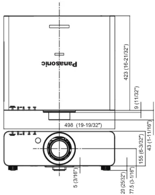
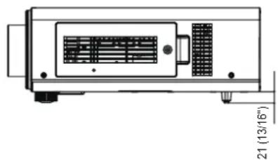
natural_image
Technical line drawing of a device with internal components and dimension标注 (no readable text or symbols)
* The above dimension is for the models with the standard zoom lens.
* Actual dimension may differ depending on the product.
Ceiling mount bracket safeguards
- When installing the projector to a ceiling, be sure to use the specified ceiling mount bracket (ET-PKD56H: for high ceilings, ET-PKD55S: for low ceilings).
- When installing the projector, attach the drop-prevention kit supplied with the ceiling mount bracket to the projector. When you wish to purchase the kit (Product No. TTRA0214), consult your dealer.
● Installation work of the ceiling mount bracket should only be performed by a qualified technician.
- Panasonic takes no responsibility for any damage to the projector resulting from use of a ceiling mount bracket not manufactured by Panasonic or the inappropriate choice of location for installation, even if the warranty period of the projector has not expired.
- An unused ceiling mount bracket must be removed promptly by a qualified technician.
- Use a torque driver or a hex torque driver when tightening the screws and tighten the screws within the minimum required tightening torque. Do not use tools such as electric screwdrivers or impact screwdrivers.
- For details, read the installation manual that comes with with the ceiling mount bracket.
● The part numbers of accessories and separately sold components are subject to change without notice.
Bottom view Model No. of ceiling mount bracket: ET-PKD56H (for high ceilings)
ET-PKD55S (for low ceilings)
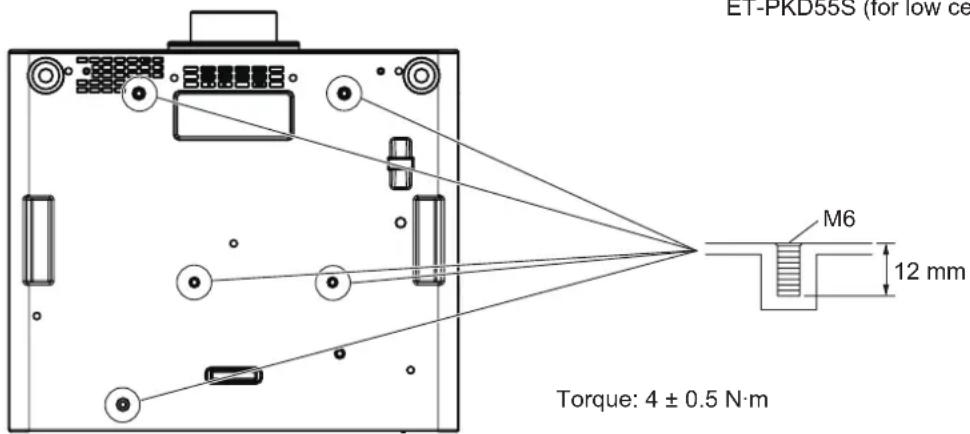
Index
A
Accessories 16
AC IN terminal 18,32
Adjustable feet 27
ADVANCED MENU 42,51
AI 47
Air filter unit 89
Air filter unit compartment 90
ASPECT 48
button
Remote control 17,40
ASPECT function 40
AUTO SETUP 57
button
Projector body 19,39
Remote control 17,39
AUTO SETUP function 39
AUTO SIGNAL 57
B
BACK COLOR 59
BLANKING 51
BRIGHTNESS 44
C
Cautions on use 15
Cautions when installing 12
Cautions when transporting 12
Ceiling mount bracket 106
Ceiling mount bracket safeguards 106
CLAMP POSITION 52
CLOCK PHASE 50
COLOR 45
COLOR CORRECTION 56
COLOR MATCHING 55
COLOR TEMPERATURE 45
Connecting the power cord 32
Connections 30
CONTRAST 44
CONTRAST MODE 56
CONTROL DEVICE SETUP 71
COOLING CONDITION 62
D
DATE AND TIME 65
button
Remote control 17,41
Deleting entry signal 68
DIGITAL CINEMA REALITY 51
Dimensions 106
Direct power off function 35
DISPLAY LANGUAGE 43,54
DISPLAY OPTION 43,55
DISPLAY SETTING 70
Disposal 14
button
Projector body 19,38
Remote control 17,38
DVI-D IN 58
E
EDGE BLENDING 52
button
Projector body 19
Remote control 17
F
Filter indicator 88
button
Remote control 17,36
FREEZE 60
button
Remote control 17,39
FUNCTION BUTTON 39,65
H
HIGH ALTITUDE MODE 61
|
button Remote control 17,20
button Remote control 17,20
INITIALIZE 66
INPUT RESOLUTION 52
K
KEYSTONE 50
L
Lamp indicator 87
LAMP POWER 63
LAMP RELAY 63
LAMP SELECT 62
Lamp unit cover 18
button
Projector body 19,36
List of compatible signals 102
LOAD ALL USER DATA 66
M
MAIN MENU 42
switch 18,34
Maintenance 89








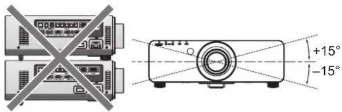
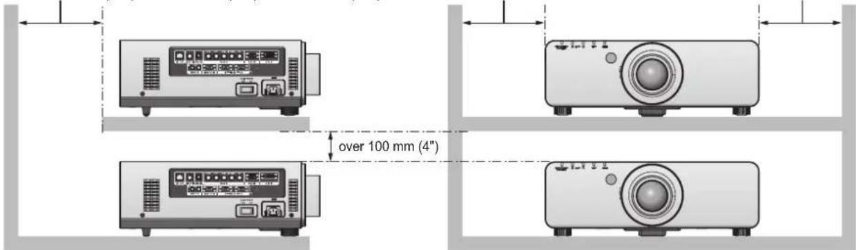


 (Only for the model with a lens)

 (For remote control unit)