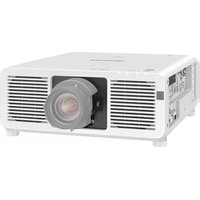
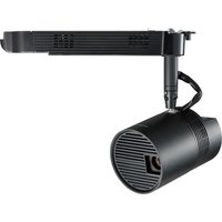
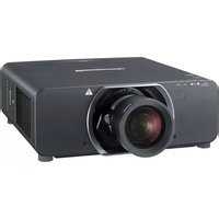
PT-REQ12L - Video projector PANASONIC - Free user manual and instructions
Find the device manual for free PT-REQ12L PANASONIC in PDF.
| Product Type | Video Projector |
| Brand | Panasonic |
| Model | PT-REQ12L |
| Display Technology | 3LCD |
| Native Resolution | WUXGA (1920 x 1200) |
| Brightness | 12,000 lumens |
| Contrast Ratio | 20,000:1 |
| Light Source | Laser |
| Lens Type | Motorized zoom/focus |
| Projection Size | 50 - 300 inches |
| Input Interfaces | HDMI x2, DisplayPort, DVI-D, VGA |
| Network | Ethernet, Wi-Fi (optional) |
| Power Consumption | 1,500 W (max) |
| Noise Level | 35 dB (normal mode) |
| Dimensions (W x D x H) | 500 x 600 x 200 mm |
| Weight | 25 kg |
| Operating Temperature | 0 - 45 °C |
| Safety Features | Laser safety, auto-shutdown |
| Maintenance | Filter cleaning every 5000 hours, lens cleaning |
| Warranty | 3 years (parts and labor) |
Frequently Asked Questions - PT-REQ12L PANASONIC
User questions about PT-REQ12L PANASONIC
0 question about this device. Answer the ones you know or ask your own.
Ask a new question about this device
Download the instructions for your Video projector in PDF format for free! Find your manual PT-REQ12L - PANASONIC and take your electronic device back in hand. On this page are published all the documents necessary for the use of your device. PT-REQ12L by PANASONIC.
USER MANUAL PT-REQ12L PANASONIC
Operating Instructions
Functional Manual
DLP™ Projector
Commercial Use
Model No. PT-REQ12
PT-REQ10
PT-REQ80

natural_image
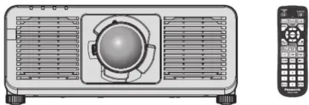
Illustration of a projector with ventilation grilles and a front-mounted control panel (no text or symbols)Thank you for purchasing this Panasonic product.
■ This manual is common to all the models regardless of suffixes of the Model No.
For details on the Model No., please refer to "Suffixes of the Model No." (→ page 2).
■ Before operating this product, please read the instructions carefully and save this manual for future use.
■ Before using this product, be sure to read "Read this first" (pages 6 to 19).

HDMI™
HIGH-DEFINITION MULTIMEDIA INTERFACE
4K*
PROFESSIONAL
* Resolution is 3 840 x 2 400 dots (QUAD PIXEL DRIVE: ON)

■ Suffixes of the Model No.
● for USA, Canada
B: Black model, the standard zoom lens supplied
LB: Black model, the lens sold separately
W: White model, the standard zoom lens supplied
LW: White model, the lens sold separately
● for United States Government
LBUG: Black model, the lens sold separately
● for EU, EFTA, UK, Turkey
BEJ: Black model, the standard zoom lens supplied
LBEJ: Black model, the lens sold separately
WEJ: White model, the standard zoom lens supplied
LWEJ: White model, the lens sold separately
- for Korea
B: Black model, the standard zoom lens supplied
W: White model, the standard zoom lens supplied
- for Taiwan
B: Black model, the standard zoom lens supplied
- for India
BD: Black model, the standard zoom lens supplied
LBD: Black model, the lens sold separately
● for other countries or regions
BE: Black model, the standard zoom lens supplied
LBE: Black model, the lens sold separately
WE: White model, the standard zoom lens supplied
LWE: White model, the lens sold separately
Contents
Read this first!
Chapter 1 Preparation
Precautions for use
Intended use of the product 24
Installation and handling of the laser product (for USA and Canada) 24
Cautions when transporting 24
Cautions when installing 24
Cautions when setting up the projector 26
Security 27
Notes regarding the wireless LAN 28
QUAD PIXEL DRIVE 28
Slot 29
DIGITAL LINK 29
Art-Net 29
Application software supported by the projector 29
Storing 30
Disposal 30
Cautions on use 30
Accessories 31
Optional accessories 32
About your projector 33
Remote control 33
Projector body 35
Names and functions of the Function Board (optional)....38
Preparing the remote control 40
Inserting and removing the batteries 40
When using the multiple projectors....40
Connecting the remote control to the projector with a cable 40
Chapter 2 Getting Started
Setting up
Usable outlet 42
Installation mode 42
Parts for installation (optional) 44
Projected image and throw distance 44
Adjusting adjustable feet 50
Removing/attaching the projection lens 51
Removing the projection lens 51
Attaching the projection lens 52
Installing the Function Board
Before installing or removing the Function Board ____
For Intel ^® SDM-S specification Function Board .54
Installing the Function Board 24
Removing the Function Board ....
Connecting
Before connecting
Connecting example: AV equipment 57
Connecting example: Computers 58
Connecting example using DIGITAL LINK....59
Connecting example when using the contrast synchronization function/shutter synchronization function ....
Chapter 3 Basic Operations
Switching on/off the projector 64
Connecting the power cord 64
Power indicator 65
Switching on the projector 66
When the initial setting screen is displayed 67
When the administrator account setting screen is displayed....73
Making adjustments and selections 75
Switching off the projector 76
Projecting
Selecting the input signal 77
Adjusting the focus, zoom, and lens shift 79
Adjusting the focus balance 80
Executing the lens calibration 80
Moving the projection lens to the home position 81
Lens shift range 82
Using the USB memory 83
Notes on use 83
USB memory that can be used with the projector....42....83
Attaching the USB memory 83
Removing the USB memory 83
Operating with the remote control 84
Using the shutter function 84
Using the on-screen display function 84
Using the function button 85
Displaying test patterns 85
Using the status function 86
Setting ID number of the remote control 86
Chapter 4 Settings
Menu navigation
Navigating through the menu 88
Main menu....89
Sub-menu 90
[PICTURE] menu 94
[PICTURE MODE] 94
[CONTRAST] 94
[BRIGHTNESS] 94
[COLOR] 95
[TINT] 95
[COLOR TEMPERATURE] 95
[WHITE GAIN] 97
[GAMMA] 97
[SYSTEM DAYLIGHT VIEW] 99
[SHARPNESS] 99
[NOISE REDUCTION] 99
[DYNAMIC CONTRAST] 99
[COLOR SPACE]....102
[SYSTEM SELECTOR]....102
[DEFAULT PICTURE MODE]....103
sRGB-compliant video 103
[POSITION] menu 105
[SHIFT] 105
[ASPECT]....105
[ZOOM] 106
[GEOMETRY]....107
[ADVANCED MENU] menu 113
[DIGITAL CINEMA REALITY]......113
[GRADATION SMOOTHER]....113
[BLANKING] 113
[EDGE BLENDING]......114
[FRAME RESPONSE]....118
[QUAD PIXEL DRIVE] 118
[RASTER POSITION]....118
[DISPLAY LANGUAGE] menu....119
Changing the display language 119
[DISPLAY OPTION] menu
[COLOR MATCHING]
[COLOR CORRECTION]
[SCREEN SETTING]
[BACKUP INPUT SETTING] 122
[HDMI IN]
[DisplayPort IN]
[SLOT IN]
[ON-SCREEN DISPLAY]
[MENU MODE]
[BACK COLOR] 139
[STARTUP LOGO]....140
[UNIFORMITY]
[SHUTTER SETTING] 141
[FREEZE] 143
[WAVEFORM MONITOR] 143
[CUT OFF] 144
[PROJECTOR SETUP] menu 145
[PROJECTOR ID] 145
[PROJECTION METHOD] 145
[LENS] 146
[SLOT SETTING] 151
[OPERATION SETTING]
[LIGHT OUTPUT] 156
[BRIGHTNESS CONTROL] 156
[STANDBY MODE] 162
[QUICK STARTUP] 162
[POWER MANAGEMENT] 163
[NO SIGNAL SETTING] 164
[INITIAL STARTUP] 167
[STARTUP INPUT SELECT]....167
[DATE AND TIME] 167
[SCHEDULE] 168
[MULTI PROJECTOR SYNC] 170
[RS-232C] 173
[REMOTE2 MODE] 174
[FUNCTION BUTTON] 175
[STATUS] 175
[INDICATOR SETTING]....179
[DATA CLONING] 180
[SAVE ALL USER DATA]....
[LOAD ALL USER DATA]....
[HDMI CEC] 181
[INITIALIZE] 183
[FIRMWARE UPDATE]......185
[SAVE LOG] 185
[SERVICE PASSWORD]
[TEST PATTERN] menu....186
[TEST PATTERN] 186
[SIGNAL LIST] menu
Registering new signals....189
Renaming the registered signal 189
Deleting the registered signal....189
Expanding signal lock-in range 190
Protecting the registered signal 190
Sub memory 191
[SECURITY] menu 192
[SECURITY PASSWORD]....192
[SECURITY PASSWORD CHANGE]....192
[CONTROL DEVICE SETUP]....193
[CONTROL DEVICE PASSWORD CHANGE] 194
[NETWORK] menu 195
[ETHERNET TYPE] 195
[DIGITAL LINK] 195
[WIRED LAN] 197
[WIRELESS LAN]....198
[PROJECTOR NAME] 199
[NETWORK STATUS]....199
[NFC SETTING] 200
[ADMINISTRATOR ACCOUNT] 201
[NETWORK SECURITY] 203
[NETWORK CONTROL] 204
[PJLink] 204
[Art-Net] 206
Chapter 5 Operations
Network connection
Connecting via wired LAN 209
Connecting via wireless LAN 211
Using the web control function 214
Computer that can be used for setting 214
Accessing from the web browser 214
[Status] 218
[Projector control] 223
[Detailed set up] 227
[Set up password] 243
License download page 245
Using the data cloning function 246
Copying the data to another projector via LAN 246
Copying the data to another projector using USB 248
Using HDMI CEC function 250
Connecting a CEC-compatible device 250
Setting the projector and CEC-compatible device 250
Operating the CEC-compatible device with the projector remote control 250
About the power link operations 251
Updating the firmware
Updating the firmware via LAN 252
Updating the firmware using the USB memory
Chapter 6 Maintenance
Light source/temperature indicators 260
When an indicator lights up ....
Maintenance
Before maintenance
Maintenance
Troubleshooting
Self-diagnosis display
Chapter 7 Appendix
Technical information
Using PJLink function 267
Using Art-Net function 269
Control commands via LAN 273
Specifications 282
Dimensions 286
List of compatible signals 287
Precautions for attaching the Ceiling Mount Bracket 298
Index 304
209
Read this first!
WARNING: THIS APPARATUS MUST BE EARTHED.
WARNING: To prevent damage which may result in fire or shock hazard, do not expose this appliance to rain or moisture.
This device is not intended for use in the direct field of view at visual display workplaces. To avoid incommoding reflexions at visual display workplaces this device must not be placed in the direct field of view.
The equipment is not intended for used at a video workstation in compliance BildscharbV.
The sound pressure level at the operator position is equal or less than 70 dB (A) according to ISO 7779.
WARNING:
- Remove the plug from the mains socket when this unit is not in use for a prolonged period of time.
- To prevent electric shock, do not remove cover. No user serviceable parts inside. Refer servicing to qualified service personnel.
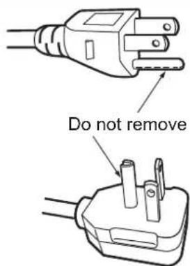
- Do not remove the earthing pin on the mains plug. This apparatus is equipped with a three prong earthing-type mains plug. This plug will only fit an earthing-type mains socket. This is a safety feature. If you are unable to insert the plug into the mains socket, contact an electrician. Do not defeat the purpose of the earthing plug.
WARNING:
This equipment is compliant with Class A of CISPR32.
In a residential environment this equipment may cause radio interference.
(for Taiwan)
WARNING:
This equipment complies with the Class A standard of CNS15936.
This is Class A information technology equipment that may cause radio frequency interference when used in a residential environment, in which the user will be required to take certain appropriate countermeasures.
CAUTION: To assure continued compliance, follow the attached installation instructions. This includes using the provided power cord and shielded interface cables when connecting to computer or peripheral devices. Also, any unauthorized changes or modifications to this equipment could void the user's authority to operate this device.
This is a device to project images onto a screen, etc., and is not intended for use as indoor lighting in a domestic environment.
Directive 2009/125/EC
WARNING: TO REDUCE THE RISK OF FIRE OR ELECTRIC SHOCK, DO NOT EXPOSE THIS PRODUCT TO RAIN OR MOISTURE.
WARNING: RISK OF ELECTRIC SHOCK. DON'T OPEN

Indicated on the projector

The lightning flash with arrowhead symbol, within an equilateral triangle, is intended to alert the user to the presence of uninsulated "dangerous voltage" within the product's enclosure that may be of sufficient magnitude to constitute a risk of electric shock to persons.

The exclamation point within an equilateral triangle is intended to alert the user to the presence of important operating and maintenance (servicing) instructions in the literature accompanying the product.
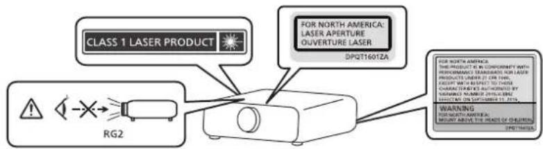
WARNING: Do not look at the light emitted from the lens while the projector is being used. As with any bright source, do not stare into the direct beam, RG2 IEC 62471-5:2015.

RG2
Indicated on the projector
(for USA and Canada)
WARNING: MOUNT ABOVE THE HEADS OF CHILDREN.
The use of a ceiling mount is recommended with this projector to place it above the eyes of children.
Laser Notice No.57
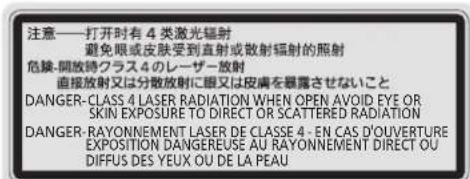
Notice on laser
(except for Taiwan, India)
This projector is the Class 1 laser product that complies with IEC/EN 60825-1:2014.


(Inside of product)
(for Taiwan)
This projector is the Class 1 laser product that complies with IEC/EN 60825-1:2014.

flowchart
graph TD
A["第 1類雷射產品"] --> B["RFID"]
C["RG2"] --> B
(for India)
This projector is the Class 1 laser product that complies with IEC/EN 60825-1:2014.

CAUTION: Use of controls or adjustments or performance of procedures other than those specified herein may result in hazardous radiation exposure.
CAUTION (North/Middle/South America)
Power Supply: This Projector is designed to operate on 100 V - 240 V, 50 Hz/60 Hz AC, house current only.
CAUTION: The AC power cord which is supplied with the projector as an accessory can only be used for power supplies up to 125 V. If you need to use higher voltages than this, you will need to obtain a separate 250 V power cord. If you use the accessory cord in such situations, fire may result.
CAUTION (North/Middle/South America, Taiwan)
This equipment is equipped with a three-pin grounding-type power plug. Do not remove the grounding pin on the power plug. This plug will only fit a grounding-type power outlet. This is a safety feature. If you are unable to insert the plug into the outlet, contact an electrician. Do not defeat the purpose of the grounding plug.

WARNING (USA and Canada)
- Not for use in a computer room as defined in the Standard for the Protection of Electronic Computer/Data Processing Equipment, ANSI/NFPA 75.
- For permanently connected equipment, a readily accessible disconnect device shall be incorporated in the building installation wiring.
- For pluggable equipment, the socket-outlet shall be installed near the equipment and shall be easily accessible.
NOTIFICATION (Canada)
This class A digital apparatus complies with Canadian ICES-003.
For USA-California Only
This product contains a CR Coin Cell Lithium Battery which contains Perchlorate Material – special handling may apply. See www.dtsc.ca.gov/hazardouswaste/perchlorate
For Australia Only
WARNING: THIS PRODUCT CONTAINS A COIN BATTERY

Keep coin battery out of the reach of infants and small children whether the battery is new or used. Severe or fatal injuries can occur within 2 hours of ingestion. Seek medical attention immediately.
EU Declaration of Conformity (DoC) for RE Directive
This equipment is in compliance with the essential requirements and other relevant provisions of Directive 2014/53/EU.
Customers can download a copy of the original DoC for this product from our DoC server: https://www.ptc.panasonic.eu/
Contact in the EU: Panasonic Connect Europe GmbH, Panasonic Testing Centre, Winsbergring 15, 22525 Hamburg, Germany
FCC NOTICE (USA)
Supplier's Declaration of Conformity
Model Number: PT-REQ12B / PT-REQ12W / PT-REQ12LB / PT-REQ12LW / PT-REQ12LBUG /
PT-REQ12BE / PT-REQ12WE / PT-REQ12LBE / PT-REQ12LWE
PT-REQ10B / PT-REQ10W / PT-REQ10LB / PT-REQ10LW /PT-REQ10LBUG /
PT-REQ10BE / PT-REQ10WE / PT-REQ10LBE / PT-REQ10LWE
PT-REQ80B / PT-REQ80W / PT-REQ80LB / PT-REQ80LW / PT-REQ80LBUG /
PT-REQ80BE / PT-REQ80WE / PT-REQ80LBE / PT-REQ80LWE
Trade Name: Panasonic
Responsible Party: Panasonic Corporation of North America
Address: Two Riverfront Plaza, Newark, NJ 07102-5490
General Contact: http://www.panasonic.com/support
Projector Contact: https://panasonic.net/cns/projector/
This device complies with Part 15 of the FCC Rules.
Operation is subject to the following two conditions:
(1) This device may not cause harmful interference, and (2) this device must accept any interference received, including interference that may cause undesired operation.
Caution:
This equipment has been tested and found to comply with the limits for a Class A digital device, pursuant to part 15 of the FCC Rules. These limits are designed to provide reasonable protection against harmful interference when the equipment is operated in a commercial environment. This equipment generates, uses, and can radiate radio frequency energy and, if not installed and used in accordance with the instruction manual, may cause harmful interference to radio communications. Operation of this equipment in a residential area is likely to cause harmful interference in which case the user will be required to correct the interference at his own expense.
FCC Warning:
To assure continued compliance, follow the attached installation instructions. This includes using the provided power cord and shielded interface cables when connecting to computer or peripheral devices. Also, any unauthorized changes or modifications to this equipment could void the user's authority to operate this device.
IMPORTANT: THE MOLDED PLUG
FOR YOUR SAFETY, PLEASE READ THE FOLLOWING TEXT CAREFULLY.
This appliance is supplied with a molded three pin mains plug for your safety and convenience. A 13 amp fuse is fitted in this plug. Should the fuse need to be replaced, please ensure that the replacement fuse has a rating of 13 amps and that it is approved by ASTA or BSI to BS1362.
Check for the ASTA mark 📊 or the BSI mark 🌘 on the body of the fuse.
If the plug contains a removable fuse cover, you must ensure that it is refitted when the fuse is replaced. If you lose the fuse cover, the plug must not be used until a replacement cover is obtained. A replacement fuse cover can be purchased from an Authorized Service Center.
If the fitted molded plug is unsuitable for the mains socket in your home, then the fuse should be removed and the plug cut off and disposed of safely. There is a danger of severe electrical shock if the cut off plug is inserted into any 13 amp socket.
If a new plug is to be fitted, please observe the wiring code as shown below. If in any doubt, please consult a qualified electrician.
WARNING: THIS APPLIANCE MUST BE EARTHED.
IMPORTANT: The wires in this mains lead are colored in accordance with the following code:
Green - and - Yellow: Earth
Blue: Neutral
Brown: Live
As the colors of the wire in the mains lead of this appliance may not correspond with the colored markings identifying the terminals in your plug, proceed as follows.
The wire which is colored GREEN - AND - YELLOW must be connected to the terminal in the plug which is marked with the letter E or by the Earth symbol 12 or colored GREEN or GREEN - AND - YELLOW.
The wire which is colored BLUE must be connected to the terminal in the plug which is marked with the letter N or colored BLACK.
The wire which is colored BROWN must be connected to the terminal in the plug which is marked with the letter L or colored RED.
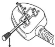
How to replace the fuse: Open the fuse compartment with a screwdriver and replace the fuse.

■ Hazard distance (IEC/EN 62471-5:2015)
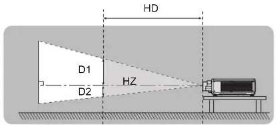
The distance from the projection lens surface, at which the emission reaches the Accessible Emission Limit (AEL) of risk group 2, is known as the hazard distance (HD) or safety distance. The area where the emission exceeds the Accessible Emission Limit of risk group 2 is called the hazard zone (HZ).
Within the hazard zone, never look into the light projected from the projector. The eyes may be damaged by direct irradiation even if you look at the light just for a moment. If you are outside the hazard zone, it is considered to be safe in all circumstances except deliberately staring into the light projected from the projector.


Risk group
The combination of the projector and the projection lens is categorized as risk group 2 when the hazard distance is 1 m (39-3/8") or less. It is categorized as risk group 3 when the hazard distance exceeds 1 m (39-3/8"), and it will be for professional use instead of consumer use.
In case of risk group 3, there is a possibility of damaging the eyes by direct irradiation when looking into the projection light from inside the hazard zone even for a moment.
In the case of risk group 2, safe use without damaging the eyes is possible in all circumstances except deliberately staring into the light projected from the projector.
The combination of the projector and the projection lens which the hazard distance exceeds 1 m (39-3/8") and is categorized as risk group 3 is as follows.
| Model No. Projection lens | Model No. Risk group | |
| PT-REQ12*1PT-REQ10*1PT-REQ80*1 | ET-C1T700 | Risk group 3 |
*1 When PT-REQ12 / PT-REQ10 / PT-REQ80 is used with the Zoom Lens (Model No.: ET-C1T700) attached, the hazard distance exceeds 1 m (39-3/8"), and regardless of the use condition, the throw ratio is larger than 2.0:1. In this case, it is categorized as the risk group 3.

Indicated on the projector
Each dimension inside the hazard zone for combination with projection lens which the hazard distance exceeds 1 m (39-3/8") is as follows.
(Unit: m)
| Model No. | Projection lens Model No. | HD*1 | D1*2 | D2*2 | D3*2 | D4*2 |
| PT-REQ12 ET-C1T700 | 2.4 0.481 | 0.481 0.553 0.553 | ||||
| PT-REQ10 PT-REQ80 | ET-C1T700 | 1.7 0.347 | 0.347 0.399 0.399 | |||
*1 HD: Hazard Distance
*2 The values of D1 to D4 will change in accordance with the lens shift amount. Each value in the table is the maximum value.
Note
- The value in the table is based on IEC/EN 62471-5:2015.
- Projection lens compatible with the projector may be added or changed without prior notice.
For the latest information, visit the following website.
https://panasonic.net/cns/projector/
Attention
- If the light projected from the projector directly enters the eyes while you are inside the hazard zone, the retinas may be damaged. Do not enter within the hazard zone during use. Alternatively, install the projector in a location where the projected light will not directly enter the eyes.
WARNING:
POWER
The wall outlet or the circuit breaker shall be installed near the equipment and shall be easily accessible when problems occur. If the following problems occur, cut off the power supply immediately.
Continued use of the projector in these conditions will result in fire or electric shock, or will cause visual impairment.
- If foreign objects or water get inside the projector, cut off the power supply.
- If the projector is dropped or the cabinet is broken, cut off the power supply.
- If you notice smoke, strange smells or noise coming from the projector, cut off the power supply.
Please contact an Authorized Service Center for repairs, and do not attempt to repair the projector yourself.
During a thunderstorm, do not touch the projector or the cable.
Electric shocks can result.
Do not do anything that might damage the power cord or the power plug.
If the power cord is used while damaged, electric shocks, short-circuits or fire will result.
- Do not damage the power cord, make any modifications to it, place it near any hot objects, bend it excessively, twist it, pull it, place heavy objects on top of it or wrap it into a bundle.
Ask an Authorized Service Center to carry out any repairs to the power cord that might be necessary.
Do not use anything other than the provided power cord.
Failure to observe this will result in electric shocks or fire. Please note that if you do not use the provided power cord to ground the device on the side of the outlet, this may result in electric shocks.
Completely insert the power plug into the wall outlet and the power connector into the projector terminal.
If the plug is not inserted correctly, electric shocks or overheating will result.
- Do not use plugs which are damaged or wall outlets which are coming loose from the wall.
Do not handle the power plug and power connector with wet hands.
Failure to observe this will result in electric shocks.
Use an outlet supporting 15 A independently.
Using an outlet together with another device may result in fires due to heat generation.
Do not overload the wall outlet.
If the power supply is overloaded (ex., by using too many adapters), overheating may occur and fire will result.
Clean the power plug regularly to prevent it from becoming covered in dust.
Failure to observe this will cause a fire.
- If dust builds up on the power plug, the resulting humidity can damage the insulation.
- If not using the projector for an extended period of time, pull the power plug out from the wall outlet.
Pull the power plug out from the wall outlet and wipe it with a dry cloth regularly.
■ ON USE/INSTALLATION
Do not place the projector on soft materials such as carpets or sponge mats.
Doing so will cause the projector to overheat, which can cause burns, fire or damage to the projector.
Do not set up the projector in humid or dusty places or in places where the projector may come into contact with oily smoke or steam.
Using the projector under such conditions will result in fire, electric shocks or deterioration of components. Oil may also distort the plastic and the projector could fall such as when mounted on the ceiling.
Do not install this projector in a place which is not strong enough to take the full weight of the projector or on top of a surface which is sloped or unstable.
Failure to observe this will cause projector to fall down or tip over the projector, and severe injury or damage could result.
Do not install the projector in a location where people pass through.
People may bump into the projector or trip on the power cord, which may result in fire, electric shock, or injury.
Install the projector in a location sufficiently away from surrounding walls and objects so that air ventilation is not obstructed.
Failure to observe this will cause the projector to overheat, which can cause fire or damage to the projector.
- Do not place the projector in narrow, badly ventilated places.
For details, refer to “Cautions when setting up the projector” ( page 26). - Do not place the projector on cloth or papers, as these materials could be drawn into the intake vent.
WARNING:
Do not look at or place your skin into the light emitted from the lens while the projector is being used.
Do not enter the projection luminous flux using an optical device (such as magnifier or mirror).
Doing so can cause burns or loss of sight.
- Strong light is emitted from the projector's lens. Do not look at or place your hands directly into this light.
- Be especially careful not to let young children look into the lens. In addition, turn off the power and switch off the main power when you are away from the projector.
Do not project an image with the lens cover attached.
Doing so can cause fire.
Never attempt to remodel or disassemble the projector.
High voltages can cause fire or electric shocks.
- For any inspection, adjustment and repair work, please contact an Authorized Service Center.
Do not allow metal objects, flammable objects, or liquids to enter inside of the projector. Do not allow the projector to get wet.
Doing so may cause short circuits or overheating, and result in fire, electric shock, or malfunction of the projector.
- Do not place containers of liquid or metal objects near the projector.
- If liquid enters inside of the projector, consult your dealer.
• Particular attention must be paid to children.
Use the ceiling mount bracket specified by Panasonic Connect Co., Ltd.
Using the ceiling mount bracket other than the specified one will result in falling accidents.
- Attach the supplied safety cable to the ceiling mount bracket to prevent the projector from falling down.
Installation work such as mounting the projector on the ceiling should only be carried out by a qualified technician.
If installation is not carried out and secured correctly, it can cause injury or accidents, such as electric shocks.
ACCESSORIES
Do not use or handle the batteries improperly, and refer to the following.
Failure to observe this will cause burns, batteries to leak, overheat, explode or catch fire.
- Do not use unspecified batteries.
- Do not charge dry cell batteries.
- Do not disassemble dry cell batteries.
- Do not heat the batteries or place them into water or fire.
- Do not allow the + and – terminals of the batteries to come into contact with metallic objects such as necklaces or hairpins.
- Do not store or carry batteries together with metallic objects.
- Store the batteries in a plastic bag and keep them away from metallic objects.
- Make sure the polarities (+ and −) are correct when inserting the batteries.
- Do not use a new battery together with an old battery or mix different types of batteries.
- Do not use batteries with the outer cover peeling away or removed.
If the battery fluid leaks, do not touch it with bare hands, and take the following measures if necessary.
- Battery fluid on your skin or clothing could result in skin inflammation or injury.
Rinse with clean water and seek medical advice immediately. - Battery fluid coming in contact with your eyes could result in loss of sight.
In this case, do not rub your eyes. Rinse with clean water and seek medical advice immediately.
Do not allow children to reach the batteries.
Accidentally swallowing them can cause physical harm.
- If swallowed, seek medical advice immediately.
Remove the depleted batteries from the remote control promptly.
- Leaving them in the unit may result in fluid leakage, overheating, or explosion of the batteries.
CAUTION:
POWER
When disconnecting the power cord, be sure to hold the power plug and power connector.
If the power cord itself is pulled, the lead will become damaged, and fire, short-circuits or serious electric shocks will result.
When not using the projector for an extended period of time, disconnect the power plug from the wall outlet.
Failure to do so may result in fire or electric shock.
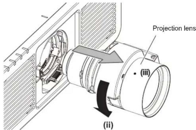
Before replacing the projection lens, be sure to turn off the power and disconnect the power plug from the wall outlet.
- Unexpected projection of light may cause injury to eyes.
- Replacing the projection lens without removing the power plug may result in electric shock.
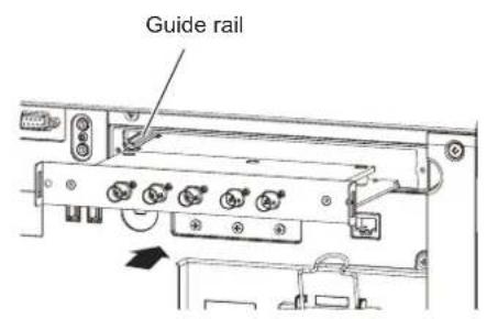
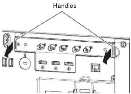
Disconnect the power plug from the wall outlet before attaching or removing the Function Board (optional) and performing maintenance.
Failure to do so may result in electric shock.
■ ON USE/INSTALLATION
Do not place heavy objects on top of the projector.
Failure to observe this will cause the projector to become unbalanced and fall, which could result in damage or injury. The projector will be damaged or deformed.
Do not put your weight on this projector.
You could fall or the projector could break, and injury will result.
- Be especially careful not to let young children stand or sit on the projector.
Do not place the projector in extremely hot locations.
Doing so will cause the outer casing or internal components to deteriorate, or result in fire.
• Take particular care in locations exposed to direct sunlight or near heaters.
Do not place your hands in the openings beside the optical lens, while shifting the lens.
Failure to observe this could cause injury.
Do not install the projector in a location where salt pollution or corrosive gas may occur.
Doing so may result in falling due to corrosion. Also, it may result in malfunctions.
Do not stand in front of the lens while the projector is being used.
Doing so can cause damage and burns to clothing.
- Strong light is emitted from the projector's lens.
Do not place objects in front of the lens while the projector is being used.
Do not block the projection by placing an object in front of the projection lens.
Doing so can cause fire, damage to an object, or malfunction of the projector.
- Strong light is emitted from the projector's lens.
The projector must be carried or installed by two or more people.
Failure to do so may cause falling accidents.
Always disconnect all cables before moving the projector.
Moving the projector with cables still attached can damage the cables, which will cause fire or electric shocks to occur.
When mounting the projector on the ceiling, keep mounting screws and power cord from contact with metal parts inside the ceiling.
Contact with metal parts inside the ceiling can cause electric shocks.
CAUTION:
ACCESSORIES
When not using the projector for an extended period of time, remove the batteries from the remote control.
Failure to observe this will cause the batteries to leak, overheat, catch fire or explode, which may result in fire or contamination of surrounding area.
■ MAINTENANCE
Ask your dealer about cleaning inside the projector every 20 000 hours of usage as an estimated duration.
Continuous use while dust is accumulated inside the projector may result in fire.
- For cleaning fee, ask your dealer.
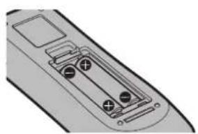
To remove the battery
Remote Control Battery
- Press the guide and lift the cover.

- Remove the batteries.

natural_image
Diagram of a remote control panel with arrows indicating clockwise movement (no text or symbols)Brazil Only
Brasil Apenas
natural_image
Diagram of a remote control panel with arrows indicating clockwise movement (no text or symbols)Disposal of Old Equipment and Batteries
Only for European Union and countries with recycling systems

These symbols on the products, packaging, and/or accompanying documents mean that used electrical and electronic products and batteries must not be mixed with general household waste. For proper treatment, recovery and recycling of old products and used batteries, please take them to applicable collection points in accordance with your national legislation.
By disposing of them correctly, you will help to save valuable resources and prevent any potential negative effects on human health and the environment.
For more information about collection and recycling, please contact your local authority. Penalties may be applicable for incorrect disposal of this waste, in accordance with national legislation.

Note for the battery symbol (bottom symbol)
This symbol might be used in combination with a chemical symbol. In this case it complies with the requirement set by the Directive for the chemical involved.
Product Information (for Turkey only)
Information on hazardous constituents as specified in the E-Waste (Management) Rules in electrical and electronic equipment.
Declaration of Conformity with the requirements of the E-Waste (Management) Rules limits with respect to Lead, Mercury, Cadmium, Hexavalent chromium, Polybrominated biphenyls, Polybrominated diphenyl ethers.
The content of hazardous substance with the exemption of the applications listed in the E-Waste (Management) Rules:
- Lead (Pb) – not over 0.1% by weight.
- Cadmium (Cd) – not over 0.01% by weight.
- Mercury (Hg) – not over 0.1% by weight.
- Hexavalent chromium (Cr6+) – not over 0.1% by weight.
- Polybrominated biphenyls (PBBs) – not over 0.1% by weight.
- Polybrominated diphenyl ethers (PBDEs) – not over 0.1% by weight.
For the purpose of recycling to facilitate effective utilization of resources, please return this product to a nearby authorized collection center, registered dismantler of recycler, or Panasonic service center when disposing of this product.
Customer care number ( Toll free ) : 1800 103 1333 ,1800 108 1333
Please see the Panasonic website for further information on collection centers, etc. or call the customer care toll-free number.
https://www.panasonic.com/in/corporate/e-waste-management.html
Do's & Don'ts
| No. | Do's Don'ts | |
| 1 | All electrical and electronic products are required to be handed over only to the Authorized recycler. | The product should not be opened by the user himself / herself, but only by authorized service personnel. |
| 2 | The product should be handed over only to authorized recycler for disposal. | The product is not meant for re-sale to any unauthorized agencies / scrap dealers / kabariwalas. |
| 3 | Keep the product in an isolated area, after it becomes non-functional / unrepairable so as to prevent its accidental breakage. | The product is not meant for mixing into household waste stream. |
| 4 | Refer to Operating Instructions for handling of end of life products | Do not keep any replaced spare part(s) from the product in an exposed area. |
| 5 | Always dispose of products that have reached end of life at Panasonic Life Solutions India Authorized Service Centre. | Do not donate old electronic items to anybody. Do not dispose of your product in garbage bins along with municipal waste that ultimately reaches landfill. |
| 6 | Wherever possible or as instructed, separate the packaging material according to responsible waste disposal options and sorting for recycling. | Do not give e-waste to informal and unorganized sectors like Local Scrap Dealers / Rag Pickers. |
Trademarks
•SOLID SHINE is a trademark of Panasonic Holdings Corporation.
- DLP and the DLP logo are registered trademarks or trademarks of Texas Instruments.
- The terms HDMI, HDMI High-Definition Multimedia Interface, HDMI Trade Dress and the HDMI Logos are trademarks or registered trademarks of HDMI Licensing Administrator, Inc.
- Intel and the Intel logo are trademarks of Intel Corporation or its subsidiaries.
- DisplayPo™ is a trademark owned by the Video Electronics Standards Association (VESA®) in the United States and other countries.
- Trademark PJLink is a trademark applied for trademark rights in Japan, the United States of America and other countries and areas.
- Crestron Connected, the Crestron Connected logo, Crestron Fusion, and XiO Cloud are either trademarks or registered trademarks of Crestron Electronics, Inc. in the United States and/or other countries.
- HDBase™ is a trademark of HDBaseT Alliance.
- Art-Net™ Designed by and Copyright Artistic Licence Holdings Ltd
- Windows and Microsoft Edge are registered trademarks or trademarks of Microsoft Corporation in the United States and other countries.
• Mac, macOS, Safari, and iPhone are trademarks of Apple Inc., registered in the U.S. and other countries and regions.
- IOS is a trademark or registered trademark of Cisco in the U.S. and other countries and is used under license.
- Android and Google Chrome are trademarks of Google LLC.
- QR Code is a registered trademark of DENSO WAVE INCORPORATED in Japan and in other countries.
- Adobe, Acrobat, and Reader are either registered trademarks or trademarks of Adobe in the United States and/or other countries.
- Some of the fonts used in the on-screen menu are Ricoh bitmap fonts, which are manufactured and sold by Ricoh Company, Ltd.
- All other names, company names, and product names mentioned in this manual are trademarks or registered trademarks of their respective owners.
Please note that the ^® and ^TM symbols are not specified in this manual.
Software information regarding this product
This product incorporates the following software:
(1) the software developed independently by or for Panasonic Connect Co., Ltd.,
(2) the software owned by third party and licensed to Panasonic Connect Co., Ltd.,
(3) the software licensed under the GNU General Public License, Version 2.0 (GPL V2.0),
(4) the software licensed under the GNU LESSER General Public License, Version 2.1 (LGPL V2.1), and/or
(5) open source software other than the software licensed under the GPL V2.0 and/or LGPL V2.1.
The software categorized as (3) - (5) are distributed in the hope that it will be useful, but WITHOUT ANY WARRANTY, without even the implied warranty of MERCHANTABILITY or FITNESS FOR A PARTICULAR PURPOSE.
For details, refer to the license terms and conditions of each open source software.
The open source software license is stored in the firmware of this product, and can be downloaded by accessing this projector using the web browser. For details, refer to “Using the web control function” ( page 214).
At least three (3) years from delivery of this product, Panasonic Connect Co., Ltd. will give to any third party who contacts us at the contact information provided below, for a charge no more than our cost of physically performing source code distribution, a complete machine-readable copy of the corresponding source code covered under GPL V2.0, LGPL V2.1 or the other licenses with the obligation to do so, as well as the respective copyright notice thereof.
Contact Information: oss-cd-request@gg.jp.panasonic.com
■Illustrations in this manual
- Illustrations of the projector, menu screen (OSD), and other parts may vary from the actual product.
- Illustrations displayed on the computer screen may differ depending on the types of the computer, operating system, and the web browser.
- Illustrations of the projector with the power cord attached are only examples. The shape of the supplied power cords varies depending on the country where you purchased the product.
■Reference pages
- Reference pages in this manual are indicated as (→ page 00).
Term
- In this manual, the "Wireless/wired remote control unit" accessory is referred to as "Remote control".
Features of the Projector
Quick Steps
For details, refer to the corresponding pages.
High image quality and fast response
▶ With a new-generation laser light source and a unique optical system enhancing the color reproduction, high luminance of 12 000 lm ^1 and high contrast of 25 000:1 ^2 are achieved. This projector also provides high realistic sensation 4K images by the QUAD PIXEL DRIVE technology. Moreover, with the 4x speed 240 Hz drive ^*3 that enables fast response, smooth and highly expressive projection is achieved even for fast-moving images.
*1 When [OPERATING MODE] is set to [NORMAL] A value for PT-REQ12.
A value for PT-REQ10 is 10 000 lm and for PT-REQ80 is 8 000 lm.
*2 When [DYNAMIC CONTRAST] is set to [3]
*3 Supports signals up to 1920x1080/240. Supports 4K signals up to 60 Hz.
High extensibility and flexible setup
▶ Flexibly supports various systems for the customers by adopting the next-generation slot specification Intel® Smart Display Module and the Art-Net function. With the lens memory function and utilizing the characteristics of solid-state light source, application to wide range of usage is possible with support of all 360° direction projection.
Long life and high reliability
In addition to adopting the solid-state light source with long life, the projector has enhanced the dust resistance property of the optical unit. By eliminating the filter, the maintenance cost for long-term operation is reduced. Also, it will contribute to the stable operation by adopting the backup function (HDMI input) that will continue the projection even when the input signal is discontinued.
- Set up the projector.
(→ page 42)

- Attach the projection lens.
(→ page 51)

- Connect with external devices.
(→ page 56)

- Connect the power cord.
(→ page 64)

- Switch on the projector.
(→ page 66)

- Make initial settings.
(→ page 67)
- Take this step when you switch on the power for the first time after purchasing the projector.

- Select the input signal.
(→ page 77)

- Adjust the image.
(→ page 79)
Chapter 1 Preparation
This chapter describes things you need to know or check before using the projector.
Precautions for use
Intended use of the product
The purpose of the projector is to project an image signal from imaging equipment or a computer on a screen or other surface as a still image or moving image.
Installation and handling of the laser product (for USA and Canada)
■For permanent Installation
• Installation of the projector shall be performed by a technician trained by Panasonic Connect Co., Ltd.
- The variance application to the U.S. Food and Drug Administration (FDA variance application) will be performed by Panasonic Connect Co., Ltd. The person responsible of the device or usage shall store the original or a copy of the FDA variance approval letter received from Panasonic Connect Co., Ltd.
■For temporary installation
- Installation of the projector shall be performed by a technician trained by Panasonic Connect Co., Ltd.
- Owner of the projector or the person responsible of usage such as the promotor of the show shall apply for FDA variance and acquire the approval letter.
- The variance holder who has acquired the FDA variance approval letter must submit the “installation checklist” required by FDA to Panasonic Connect Co., Ltd.
- Variance holder shall create and store a document recording the information such as the location of the use, dates of the use, users of the projector.
For use
- This projector is categorized as the risk group 3 of IEC/EN 62471-5:2015.
- Do not enter within the hazard distance (within RG3 range), refer to "Hazard distance (IEC/EN 62471-5:2015)".
- Assign a person responsible of the device when using the projector. The person responsible shall be trained by Panasonic Connect Co., Ltd. before starting to use the projector.
Note
- Information such as training, FDA variance application, installation checklist, usage recording document can be confirmed by accessing following URL.
https://eww.pavc.panasonic.co.jp/projector/extranet/index.html
Cautions when transporting
- Transport the projector with two or more people. Failure to do so may drop the projector, which may result in damage or deformation of the projector, or injury.
- Hold the bottom of the projector and do not hold the projection lens or the opening around the projection lens when transporting. Failure to do so may cause damage. Also, handle the projector in a way not to apply excessive vibration or shock. Failure to do so may cause a failure due to the damaged internal components.
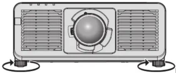
- Do not transport the projector with the adjustable feet extended. Doing so may damage the adjustable feet.
Cautions when installing
■Do not set up the projector outdoors.
The projector is designed for indoor use only.
■Do not set up the projector in the following locations.
- Places where vibration and impacts occur such as in a car or vehicle: Doing so may cause damage to internal components or malfunction.
- Location close to sea or where corrosive gas may occur: The projector may fall due to corrosion. Also, failure to do so may shorten the life of the components and result in malfunctions.
-
Near the exhaust of an air conditioner: Depending on the conditions of use, the screen may fluctuate in rare cases due to the heated air from the exhaust vent or the hot or cooled air from the air conditioner. Make sure that the exhaust from the projector or other equipment, or the air from the air conditioner does not blow toward the front of the projector.
-
Places with sharp temperature fluctuations such as near lights (studio lamps): Doing so may shorten the life of the light source, or result in deformation of the projector due to heat, which may cause malfunctions. Follow the operating environment temperature of the projector.
- Near high-voltage power lines or near motors: Doing so may interfere with the operation of the projector.
- Places where there is high-power laser equipment: Directing a laser beam onto the projection lens surface causes damage to the DLP chips.
■ Ask a qualified technician or your dealer for the installation work such as installing to a ceiling.
To ensure projector performance and security, ask a qualified technician or your dealer when installing the projector in a method other than the floor installation or when installing the projector in a high place.
■ Ask a qualified technician or your dealer to install the cable wiring for DIGITAL LINK connection.
Image and sound may be disrupted if cable transmission characteristics cannot be obtained due to inadequate installation.
■ The projector may not work properly due to strong radio wave from the broadcast station or the radio.
If there is any facility or equipment which outputs strong radio waves near the installation location, install the projector at a location sufficiently far from the source of the radio waves. Or, wrap the LAN cable connected to the
■Image adjustment after installation
Projected image of the projector is affected by the ambient temperature around the projector or the increased internal temperature caused by the light from its light source, and it will be unstable especially right after the projection has started.
It is recommended to perform the focus adjustment after 30 minutes have elapsed with the focus test pattern displayed. For details of the test pattern, refer to “[TEST PATTERN] menu” ( page 186).
■ Do not install the projector at an altitude of 4 200 m (13 780') or higher above sea level. (Altitude of 4 200 m (13 780') above sea level is the maximum height that the performance of this projector is guaranteed.)
■ Do not use the projector in a location where the ambient temperature exceeds 45 °C (113 °F).
Using the projector in a location where the altitude is too high or the ambient temperature is too high may reduce the life of the components or result in malfunctions.
Upper limit of the operating environment temperature varies depending on the altitude above sea level.
When using the projector at an altitude between 0 m (0') and 1 400 m (4 593') above sea level: 0 °C (32 °F) to 45 °C (113 °F)
When using the projector at an altitude between 1 400 m (4 593') and 4 200 m (13 780') above sea level: 0 °C (32 °F) to 40 °C (104 °F)
Do not use the projector in a location where the ambient temperature exceeds 40 °C ( 104 °F ) regardless of the altitude when the optional Wireless Module (Model No.: AJ-WM50 Series) is attached to the projector.
■Projection in all 360° direction is possible.

Cautions when setting up the projector
- Use the adjustable feet only for the floor standing installation and for adjusting the angle. Using them for other purposes may damage the projector.
- When installing the projector with a method other than the floor installation using the adjustable feet or the ceiling installation with the Ceiling Mount Bracket, use the five screw holes for ceiling mount (as shown in the figure) to fix the projector to the mount.
In such case, make sure that there is no clearance between the screw holes for ceiling mount on the projector bottom and the setting surface by inserting spacers (metallic) between them.
- Use a torque screwdriver or Allen torque wrench to tighten the fixing screws to their specified tightening torques. Do not use electric screwdrivers or impact screwdrivers.
For the screws to fix the projector, use commercially available ISO 898-1 standard screws (made of carbon steel or alloy steel).
(Screw diameter: M6, tapping depth inside the projector: 12 mm (15/32"), screw tightening torque: 4 ± 0.5 N·m)
Unit: mm

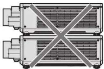
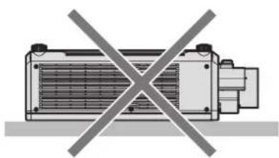
- Do not stack projectors on top of each other.
- Do not use the projector supporting it by the top.

natural_image
Diagram of two identical mechanical components with a diagonal X-marked cross symbol, no text or labels present.
natural_image
Diagram of a heat exchanger with no text or symbols, crossed by a diagonal line (no readable labels or symbols)- Do not block the intake/exhaust vents of the projector.
- Prevent hot and cool air from the air conditioning system to blow directly to the intake/exhaust vents of the projector.

100 mm (3-15/16") or shorter 100 mm (3-15/16
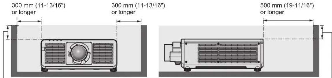
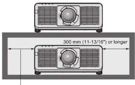
- Do not install the projector in a confined space.
When installing the projector in a confined space, provide air conditioning or ventilation separately. Exhaust heat may accumulate when the ventilation is not enough, triggering the protection circuit of the projector.

300 mm (11-13/16") or longer

100 mm (3-15/16") or longer
- When installing and fixing the projector on a ceiling or wall using a mount, make sure that the fixing screw or power cord does not come in contact with the metal section inside the ceiling or wall. Failure to observe this may result in electric shocks.
- Panasonic Connect Co., Ltd. takes no responsibility for any damage to the product caused by an inappropriate choice of location for installing the projector, even if the warranty period of the product has not expired.
- Immediately remove the product that is not in use anymore by asking a qualified technician.
Security
When using this product, take safety measures against the following incidents.
- Personal information being leaked via this product
- Unauthorized operation of this product by a malicious third party
- Interfering or stopping of this product by a malicious third party
Take sufficient security measures.
•Make your password difficult to guess as much as possible.
- Change your password periodically.
- Panasonic Connect Co., Ltd. or its affiliate companies will never ask for your password directly. Do not divulge your password in case you receive such inquiries.
•The connecting network must be secured by a firewall, etc.
■Security when using the wireless LAN product
The advantage of a wireless LAN is that information can be exchanged between a computer or other such equipment and a wireless access point using radio waves, instead of using a LAN cable, as long as you are within range for radio transmissions.
On the other hand, because the radio wave can travel through an obstacle (such as a wall) and is accessible from anywhere within a given range, following problems may occur if security setting is insufficient.
•Transmitted data may be intercepted
A malicious third party may intentionally intercept radio waves and monitor the following transmitted data.
-Personal information such as your ID, password, credit card number
-Content of an Email
- Illegally accessed
A malicious third party may access your personal or corporate network without authorization and engage in the following types of behavior.
-Retrieve personal and/or secret information (information leak)
- Spread false information by impersonating a particular person (spoofing)
- Overwrite intercepted communications and issue false data (tampering)
- Spread harmful software such as a computer virus and crash your data and/or system (system crash)
Since most wireless LAN adapters or access points are equipped with security features to take care of these problems, you can reduce the possibility of these problems occurring when using this product by making the appropriate security settings for the wireless LAN device.
Some wireless LAN devices may not be set for security immediately after purchase. To decrease the possibility of occurrence of security problems, be sure to make all security related settings according to the operation instructions supplied with each wireless LAN device before using a wireless LAN device.
Depending on the specifications of the wireless LAN, a malicious third party may be able to break security settings by special means.
Panasonic Connect Co., Ltd. asks customers to thoroughly understand the risk of using this product without making security settings, and recommends that the customers make security settings at their own discretion and responsibility.
Notes regarding the wireless LAN
Radio wave in the 2.4 GHz band is used when the wireless LAN connection function of the projector is used. The license of wireless station is not required, but understand the following when using.
To use the wireless LAN function with the projector, it is necessary to attach the optional Wireless Module (Model No.: AJ-WM50 Series).
■Do not use close to other wireless devices.
Following devices may be using radio wave in the same bandwidth as the projector. Using the projector close to these devices may cause the communication to be disabled or the communication speed to slow down due to interference of radio wave.
- Microwave oven, etc.
- Industrial, scientific, or medical devices, etc.
- In-plant wireless station for identifying moving vehicles used in the manufacturing lines at a plant
- Specified low power wireless station
■ Do not use cell phone, television, or radio as much as possible close to the projector.
Cell phone, television, or radio is using radio wave with different bandwidth from the projector, so there is no effect on the wireless LAN communication or the send/receive on these devices. However, noise may occur in the audio or video due to the radio wave from the projector.
■ Radio wave for wireless LAN communication does not go through the reinforcing bars, metal, or concrete.
The projector can communicate through wall or floor made of wood or glass (excluding the glass with metal mesh embedded), but it cannot communicate through wall or floor made of reinforcing bars, metal, or concrete.
■ Do not use the projector as much as possible in a location where static electricity is generated.
The communication via wireless LAN or wired LAN may be prone to disruption when the projector is used in a location where static electricity or noise is generated.
There is a rare case that the LAN connection may not be established due to static electricity or noise, so in such case, turn off the projector, remove the source of problematic static electricity or noise, and turn the projector back on.
QUAD PIXEL DRIVE
"QUAD PIXEL DRIVE" is a technology unique to Panasonic Connect Co., Ltd. that will enhance the resolution of the projected image with the signal processing for the high resolution of up to 3 840 x 2 400 dots and quadrupling the resolution by shifting the image pixels in horizontal and vertical directions. A 4K image is displayed by this QUAD PIXEL DRIVE technology.
Slot
This projector is equipped with Intel® Smart Display Module (Intel® SDM) specification slot.
Optional Function Board or an interface board or module of other manufacturers supporting Intel® SDM Small (Intel® SDM-S) or Intel® SDM Large (Intel® SDM-L) specification (collectively referred to as "Function Board" hereinafter) can be installed in the slot. For the devices of other manufacturers that the operation has been verified with this projector, visit the following website.
https://panasonic.net/cns/projector/
Confirmation of operation for the devices of other manufacturers has been performed with the items set independently by Panasonic Connect Co., Ltd., and not all the operations are warranted. For operation or performance problems caused by the devices of other manufacturers, contact the respective manufacturers.
DIGITAL LINK
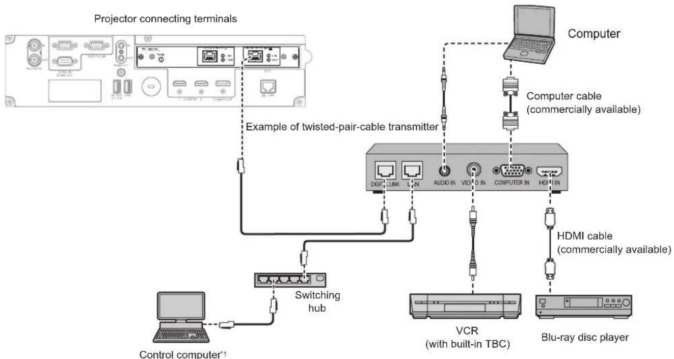
“DIGITAL LINK” is a technology to transmit the video, audio, Ethernet, and serial control signals using a twisted pair cable by adding unique functions by Panasonic Connect Co., Ltd. to the HDBase ^™ communication standard formulated by HDBaseT Alliance.
By installing the optional DIGITAL LINK Terminal Board (Model No.: TY-SB01DL) in the slot on the projector, connection with the optional DIGITAL LINK output supported device (Model No.: ET-YFB100G, ET-YFB200G) or the peripheral devices by other manufacturers based on the HDBaseT™ standard (twisted-pair-cable transmitters such as the "XTP transmitter" of Extron Electronics) becomes possible. For the devices of other manufacturers that the operation has been verified with this projector, visit the following website.
https://panasonic.net/cns/projector/
Confirmation of operation for the devices of other manufacturers has been performed with the items set independently by Panasonic Connect Co., Ltd., and not all the operations are warranted. For operation or performance problems caused by the devices of other manufacturers, contact the respective manufacturers. The projector is not equipped with an audio function so it is not possible to output audio.
Art-Net
"Art-Net" is an Ethernet communication protocol based on the TCP/IP protocol.
By using the DMX controller and the application software, illumination and stage system can be controlled. Art-Net is made based on DMX512 communication protocol.
Application software supported by the projector
The projector supports following application software.
For details or downloading application software except for “Geometric & Setup Management Software” and “Projector Network Setup Software”, visit the following website.
https://panasonic.net/cns/projector/
"Geometric & Setup Management Software" and "Projector Network Setup Software" can be downloaded from the following website ("Panasonic Professional Display and Projector Technical Support Website").
https://panasonic.net/cns/projector/pass/
It is necessary to register and login to PASS ^*1 to download from “Panasonic Professional Display and Projector Technical Support Website”.
*1 PASS: Panasonic Professional Display and Projector Technical Support Website
- Logo Transfer Software
This application software transfers the original image, such as company logo, which is projected at the start, to the projector.
•Smart Projector Control
This application software sets and adjusts the projector connected to the network using a smartphone or a tablet.
•Multi Monitoring & Control Software
This application software monitors and controls the multiple display devices (projector and flat panel display) connected to an intranet.
•Early Warning Software
This plug-in software monitors the status of the display devices and their peripherals within an intranet, and notifies of abnormality of such equipment and detects the signs of possible abnormality. “Early Warning Software” is pre-installed in the “Multi Monitoring & Control Software”. To use the early warning function of this plug-in software, install “Multi Monitoring & Control Software” in the PC to be used. By enabling the early warning function, it will notify of the approximate time to replace the consumables for the display devices, to clean each part of the display devices, and to replace the components of the display devices, allowing to execute maintenance in advance.
The early warning function can be used by registering maximum of 2048 display devices free of charge for 90 days after installing the “Multi Monitoring & Control Software” into a PC. To continuously use after the 90 days, it is necessary to purchase the license of “Early Warning Software” (ET-SWA100 Series) and perform the activation. Also, depending on the type of license, the number of display devices that can be registered for monitoring varies. For details, refer to the Operating Instructions of “Multi Monitoring & Control Software”.
- Geometric & Setup Management Software (Geometry Manager Pro)
This application software performs detailed corrections and adjustments such as the geometric adjustment which cannot be covered by the projector settings in real-time. Also, the geometric adjustment and edge blending to match the shape of the screen, and the adjustment of color and luminance can be automatically performed within simple steps by using a camera.
- Projector Network Setup Software
This application software allows to set the network information, such as the IP addresses, and the projector names, for multiple projectors connected to the network collectively. Also, the administrator account, network information, and projector name can be set for the projector that does not have the administrator account set using this software.
Storing
To store the projector, store in a dry room.
Disposal
To dispose of the product, ask your local authorities or dealer for correct methods of disposal. Also, dispose of the product without disassembling.
Cautions on use
■To get a good picture quality
In order to view a beautiful image in higher contrast, prepare an appropriate environment. Draw curtains or blinds over windows and turn off any lights near the screen to prevent outside light or light from indoor lamps from shining onto the screen.
■ Do not touch the surface of the projection lens with your bare hands.
If the surface of the projection lens becomes dirty from fingerprints or anything else, this will be magnified and projected onto the screen.
Attach the lens cover supplied with the projector or with the optional projection lens to the projector when you do not use the projector.
■DLP chips
- The DLP chips are precision-made. Note that in rare cases, pixels of high precision could be missing or always lit. Such a phenomenon does not indicate malfunction.
- Directing a high-power laser beam onto the projection lens surface can damage the DLP chips.
■ Do not move the projector or subject it to vibration or impact while it is operating.
Doing so may shorten the life of the built-in motor.
Light source
The light source of the projector uses laser diode, and has the following characteristics.
- Depending on the operating environment temperature, the luminance of the light source will decrease.
The higher the temperature becomes, the more the luminance of the light source decreases. - The luminance of the light source will decrease by duration of usage.
If brightness is noticeably reduced and the light source does not turn on, ask your dealer to clean inside the projector or replace the light source unit.
■Computer and external device connections
When connecting a computer or an external device, read this manual carefully regarding the use of power cords and shielded cables as well.
Accessories
Make sure that the following accessories are provided with your projector. Numbers enclosed in < > show the number of accessories.
Wireless/wired remote control unit <1>
(N2QAYA000252)

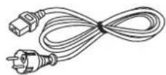
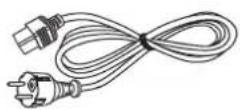
Power cord
(K2CM3YY00057)
200 V - 240 V

(K2CT3YY00101)
200 V - 240 V

(K2CG3YY00218)
100 V - 120 V

For Korea
(K2CZ3YY00032) <1>
200 V - 240 V

For India
(K2CZ3YY00100) <1>
200 V - 240 V

For Taiwan
(K2CH3YY00009) <1>
200 V - 240 V

AAA/R03 or AAA/LR03 battery <2>

(For remote control unit)
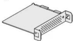
SLOT adapter <1>
(DPVF2722YA/X1)

Attention
• After unpacking the projector, discard the power cord cap and packaging material properly.
- Do not use the supplied power cord for devices other than this projector.
- For lost accessories, consult your dealer.
- Store small parts in an appropriate manner, and keep them away from young children.
Note
- The SLOT adapter is used when the Intel® SDM Small (Intel® SDM-S) specification Function Board is installed in the slot on the projector. (▶ page 53)
- The type and number of the supplied power cords vary depending on the country or region where you purchased the product.
- The part numbers of accessories are subject to change without prior notice.
Optional accessories
| Optional accessories (product name) Model No. | ||
| Projection lens Zoom Lens | ET-C1W300, ET-C1W400*1, ET-C1W500*1, ET-C1S600*2, ET-C1T700*1 | |
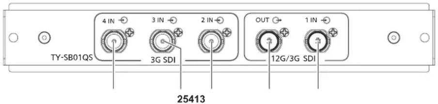
| Function Board | 12G-SDI Terminal Board*3 | TY-SB01QS |
| DIGITAL LINK Terminal Board*3 | TY-SB01DL | |
| Wireless Presentation System Receiver Board*3 | TY-SB01WP | |
| Wireless Module*3 | AJ-WM50 Series*4 | |
| Ceiling Mount Bracket | ET-PKD120H (for High Ceilings)ET-PKD120S (for Low Ceilings)ET-PKD130H (for High Ceilings, 6-axis Adjustment)ET-PKD130B (Projector Mount Bracket) | |
| Early Warning Software(Basic license/3-year license) | ET-SWA100 Series*5 | |
| NFC Upgrade Kit*3 | ETNUK10 | |
| Digital Interface Box ET-YFB100G | ||
| DIGITAL LINK Switcher ET-YFB200G | ||
*1 The optional Zoom Lens (Model No.: ET-C1W400, ET-C1W500, ET-C1T700) is scheduled to be released sequentially during July-September 2023.
*2 This product is equivalent to the lens attached to the projector model with standard zoom lens.
*3 The availability of this product varies depending on the country. For details, contact your dealer.
*4 The suffix of the Model No. differs depending on the country.
Example of the Model No. with suffix for AJ-WM50 Series
AJ-WM50E, AJ-WM50G1, AJ-WM50G2, AJ-WM50GAN, AJ-WM50GPX, AJ-WM50P
*5 The suffix of the Model No. differs according to the license type.
Note
- Use the Wireless Module (Model No.: AJ-WM50 Series) in an environment of 0 °C (32 °F) to 40 °C (104 °F), including when it is attached to the projector.
- The optional NFC Upgrade Kit (Model No.: ET-NUK10) can be used to enable the NFC function of the projector. Note that there are some models that have the NFC function enabled from the time of factory shipment, and there are some countries or regions where the NFC Upgrade Kit cannot be applied.
For the availability of the NFC function in the country or region where you purchased the product, visit the following website or consult your dealer.
https://panasonic.net/cns/projector/
- To connect the DIGITAL LINK Switcher (Model No.: ET-YFB200G) or the Digital Interface Box (Model No.: ET-YFB100G) to the projector, it is necessary to install the optional DIGITAL LINK Terminal Board (Model No.: TY-SB01DL) in the slot.
- The model numbers of optional accessories are subject to change without prior notice.
- The optional accessories compatible with the projector may be added or changed without prior notice. The optional accessories described in this document are as of April 2023.
For the latest information, visit the following website.
https://panasonic.net/cns/projector/
About your projector
Remote control
Front

Top

natural_image
Close-up of a black electronic device with two circular ports and a labeled dimension (18), no readable text or symbols beyond the number.■ Bottom

natural_image
Close-up of a black ergonomic device with a circular button and pointer labeled '19' (no text or symbols on the device itself)1 button
Sets the projector to the state where the projector is turned off (standby mode) when the
2 button
Sets the projector to projection mode when the
3 Remote control indicator
Blinks if any button in the remote control is pressed.
4 Lens buttons (, , )
Adjusts the focus, zoom, and lens shift. (→ page 79)
5
Used to navigate through the menu screen. (→ page 88)
▲▼◀▶ buttons are also used to enter the password in [SECURITY] or enter characters.
6 button
Switches the on-screen display function on (display) or off (hide). (→ page 84)
7 button
Displays the input selection screen. (→ page 78)
8 Input selection buttons (, , , )
Switches the input signal to project. (→ page 77)
9 button
Assigns a frequently used operation as a shortcut button. (→ page 85)
When the
10 Number (<0> - <9>) buttons
Used for entering an ID number or a password in a multiple projector environment.
11 button
Used to simultaneously control all the projectors with a single remote control in a multi-projector environment. (→ page 40)
12 button
Used to temporarily turn off the image. (→ page 84)
13 button
Displays the test pattern. (→ page 85)
14 button
Displays the HDMI CEC operation screen. (→ page 250)
15 button
Displays the projector information.
16 button
Resets the setting of the displayed sub-menu to the factory default. (→ page 89)
17 button
Sets the ID number of the remote control in a multiple projector environment. (→ page 40)
18 Remote control signal transmitter
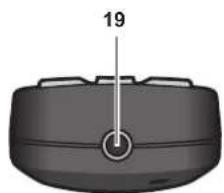
19 Remote control wired terminal
This is a terminal used to connect to the projector via a cable when the remote control is used as a wired remote control. (→ page 40)
Attention
- Do not drop the remote control.
- Avoid contact with liquids or moisture.
- Do not attempt to modify or disassemble the remote control.
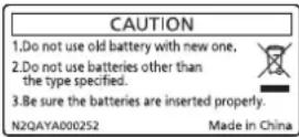
- Observe the following instructions that are indicated on the caution label at the back of the remote control:
-Do not use old battery with new one.
-Do not use batteries other than the type specified.
-Be sure the batteries are inserted properly.
For other instructions, read the instructions related to batteries that are described in "Read this first!".

Caution label at the back of the remote control
Note
- When operating the remote control by directly pointing at the remote control signal receiver of the projector, operate the remote control within a distance approximately 30 m (98'5") from the remote control signal receiver. The remote control can control at angles of up to ± 30^ vertically and horizontally, but the effective control range may be reduced.
- If there are any obstacles between the remote control and the remote control signal receiver, the remote control may not operate properly.
- The signal will be reflected off the screen. However, the operating range may be limited from light reflection loss due to the screen material.
- If the remote control signal receiver directly receives strong light, such as fluorescent light, the remote control may not operate properly. Use it in a place distant from the light source.
- The power indicator
will blink if the projector receives a remote control signal. However, the power indicator will not blink in following cases.
- When [PROJECTOR SETUP] menu → [STANDBY MODE] is set to [ECO] and the projector is in standby mode
- When [PROJECTOR SETUP] menu → [INDICATOR SETTING] → [INDICATOR MODE] is set to [OFF]
Projector body
Front

Side


natural_image
Technical line drawing of a mechanical or electronic component with internal grid structure and mounting points (no text or symbols)Rear


Top

Bottom


natural_image
Top-down schematic of a device layout with labeled components (no text or symbols)
: Projection direction
1 Remote control signal receiver (front)
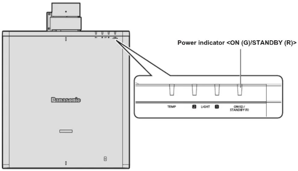
2 Power indicator
3 Light source indicator
4 Light source indicator
5 Temperature indicator
6 Adjustable feet
Adjusts the projection angle.
7 Intake vent
8 Projection lens
(Only models with lens)
9 Remote control signal receiver (rear)
10 Exhaust vent
Attention
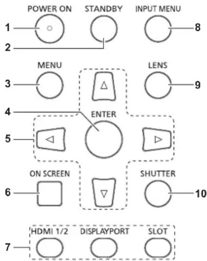
11 Control panel (→ page 36)
12 Security slot
This security slot is compatible with the Kensington security cables.
13 Connecting terminals (→ page 37)
14
Turns on/off the main power.
15
Connect the supplied power cord.
16 Power cord holder
17 NFC touch point
This is the touch point when using the near field communication (NFC, Near Field Communication) function. A device such as a smartphone equipped with the NFC function can be connected to the projector by holding it near the touch point.
18 Security bar
A wire, etc., can be attached to prevent theft.
Note
- The optional NFC Upgrade Kit (Model No.: ET-NUK10) can be used to enable the NFC function of the projector. Note that there are some models that have the NFC function enabled from the time of factory shipment, and there are some countries or regions where the NFC Upgrade Kit cannot be applied.
For the availability of the NFC function in the country or region where you purchased the product, visit the following website or consult your dealer.
https://panasonic.net/cns/projector/
- For the connection using the NFC function, use the application software "Smart Projector Control" which performs the setting and adjustment of the projector.
For details of the "Smart Projector Control", visit the following website.
https://panasonic.net/cns/projector/
■Control panel

1 button
Sets the projector to projection mode when the
2 button
Sets the projector to the state where the projector is turned off (standby mode) when the
3
Displays or hides the main menu. (→ page 88) Returns to the previous menu when a sub-menu is displayed. If you press the
- When a LAN cable is directly connected to the projector, the network connection must be made indoors.
- When connecting a USB memory to the
terminal, also refer to "Using the USB memory" (→ page 83). - When the [PROJECTOR SETUP] menu → [STANDBY MODE] is set to [NORMAL], power can be supplied by using the
terminal even while the projector is in standby mode. If [ECO] is set, power cannot be supplied in standby mode.
Names and functions of the Function Board (optional)
This projector is equipped with Intel® Smart Display Module (Intel® SDM) specification slot.
Function Board supporting the Intel ^® SDM Small (Intel ^® SDM-S) or the Intel ^® SDM Large (Intel ^® SDM-L) specification can be installed in the slot.
The terminal names of the optional Function Board with image input terminal to be used in this document is defined here, and also their operations are explained. Also refer to the Operating Instructions of the Function Board.
12G-SDI Terminal Board (Model No.: TY-SB01QS)
This board supports the HD-SDI signal, 3G-SDI signal, and 12G-SDI signal.

1
This is a terminal to input SDI signal (HD-SDI/3G-SDI).
2
This is a terminal to input SDI signal (HD-SDI/3G-SDI).
3
This is a terminal to input SDI signal (HD-SDI/3G-SDI).
4
This is an active through terminal to output the SDI signal (HD-SDI/3G-SDI/12G-SDI) input to the
5
This is a terminal to input SDI signal (HD-SDI/3G-SDI/12G-SDI).
Note
- The
/ / terminals are used when the quad link signal is input. These terminals do not support input of 12G-SDI signal. - When the projector is in standby mode, a signal is not output from the
terminal. - This projector is not equipped with an audio function so it is not possible to output audio, but the audio signal input to the
terminal is output from the terminal.
DIGITAL LINK Terminal Board (Model No.: TY-SB01DL)
This board supports the DIGITAL LINK signal.

1 Power status indicator
On:
The power is supplied to the Function Board.
The [DISPLAY OPTION] menu → [SLOT IN] → [DIGITAL LINK OUT] is set to [ENABLE].
Blinking:
The power is supplied to the Function Board.
The [DISPLAY OPTION] menu → [SLOT IN] → [DIGITAL LINK OUT] is set to [DISABLE].
Off:
The power is not supplied to the Function Board.
2
This is a terminal to output DIGITAL LINK signal input to the
3 Signal status indicator
On:
DIGITAL LINK signal is input or output.
Blinking:
Only the Ethernet signal is input or output.
Off:
DIGITAL LINK signal is not input or output.
4 Image signal indicator
On:
An image signal protected with HDCP is input or output.
Blinking:
An image signal that is not protected with HDCP is input or output.
Off:
An image signal is not input or output.
5
This is a terminal to connect a device that transmits an image signal via the LAN terminal. Also, this is the LAN terminal to connect to the network.
Note
- To transmit the Ethernet and serial control signals using the
terminal, set the [NETWORK] menu → [ETHERNET TYPE] to [DIGITAL LINK] or [LAN & DIGITAL LINK]. -
To transmit the Ethernet signal using the
terminal equipped on the projector as standard, set the [NETWORK] menu → [ETHERNET TYPE] to [LAN] or [LAN & DIGITAL LINK]. -
The
terminal and the terminal equipped on the projector as standard are connected inside of the projector when the [NETWORK] menu → [ETHERNET TYPE] is set to [LAN & DIGITAL LINK]. Do not directly connect the terminal and the terminal using a LAN cable. Construct the system so that it is not connected to the same network via the peripherals such as the hub or the twisted-pair-cable transmitter. - The DIGITAL LINK signal is output only when a display device (projector or flat panel display) that corresponds to any of the following is connected to the
terminal. - Panasonic Connect Co., Ltd. display device supporting the DIGITAL LINK input
- Display device installed with the Panasonic Connect Co., Ltd. Function Board supporting the DIGITAL LINK input
- When the [DISPLAY OPTION] menu → [SLOT IN] → [DIGITAL LINK OUT] is set to [ENABLE] and the projector is in projection mode, the DIGITAL LINK signal (including the audio signal) input to the
terminal is output from the terminal. - When the projector is in standby mode, the DIGITAL LINK signal input to the
terminal is not output from the terminal.
Preparing the remote control
Inserting and removing the batteries


natural_image
Diagram of a remote control panel with labeled ports and connectors (no text or symbols)Fig. 1 Fig. 2
1) Open the cover. (Fig. 1)
2) Insert the batteries and close the cover (insert the ⬤ side first). (Fig. 2)
- When removing the batteries, perform the steps in reverse order.
When using the multiple projectors
When you use the multiple projectors together, you can operate all the projectors simultaneously or each projector individually using single remote control, if a unique ID number is assigned to each projector.
When using the projectors by setting the ID numbers, set the ID number of the projector body after initial settings have been completed. Then, set the ID number of the remote control. For initial settings, refer to "When the initial setting screen is displayed" (→ page 67).
The factory default ID number of the projector (projector body and remote control) is set to [ALL], so you can use it as it is. Set the ID numbers of the projector body and remote control as necessary.
For details on setting the ID number of the remote control, refer to "Setting ID number of the remote control" (→ page 86).
Note
- Set the ID number of the projector body from the [PROJECTOR SETUP] menu → [PROJECTOR ID].
Connecting the remote control to the projector with a cable
If you control the multiple projectors with a single remote control, use commercially available M3 stereo mini jack cables to connect to the
The remote control is effective even in places where an obstacle stands in the light path or where devices are susceptible to outside light.

Attention
- Use a cable that is 15 m (49'3") or shorter, with 2 core shielded. The remote control may not operate when the length of the cable exceeds 15 m (49'3") or when the shielding of the cable is inadequate.
Chapter 2 Getting Started
This chapter describes things you need to do before using the projector such as the setup and connections.
Setting up
Usable outlet
This projector supports AC 100 V to AC 240 V as the power supply. A grounded outlet supporting 15 A is required with either voltage.
The shape of the usable outlet differs depending on the power supply. Following illustrations are examples.

2P/3W 15 A 250 V

2P/3W 20 A 250 V

2P/3W 15 A 250 V

2P/3W 15 A 250 V

2P/3W 15 A 125 V
Attention
- Use the supplied power cord and ground at the outlet.
- Use the power cord matching the used power supply voltage and outlet shape.
Note
- The supplied power cords vary depending on the country or region where you purchased the product.
Installation mode
The installation modes of the projector are as follows. Set [FRONT/REAR] / [FLOOR/CEILING] in the [PROJECTOR SETUP] menu → [PROJECTION METHOD] (→ page 145) depending on the installation mode.
| Setting on a desk/floor and projecting forward Setting on a desk/floor and projecting from rear(Using the translucent screen) | |||
![]() | ![]() | ||
| Menu item Setting value | Menu item Setting value | ||
| [FRONT/REAR] [FRONT] | [FRONT/REAR] [REAR] | ||
| [FLOOR/CEILING] [AUTO] | or [FLOOR] [FLOOR/CEILING] [AUTO] or [FLOOR] | ||
| Mounting on the ceiling and projecting forward Mounting on the ceiling and projecting from rear(Using the translucent screen) | |||
![]() | ![]() | ||
| Menu item Setting value | Menu item Setting value | ||
| [FRONT/REAR] [FRONT] | [FRONT/REAR] [REAR] | ||
| [FLOOR/CEILING] | [AUTO] or [CEILING] | [FLOOR/CEILING] | [AUTO] or [CEILING] |
| Portrait setting and projecting forward Portrait setting and projecting from the rear(Using the translucent screen) | |||
![]() | ![]() | ||
| Menu item Setting value | Menu item Setting value | ||
| [FRONT/REAR] [FRONT] | [FRONT/REAR] [REAR] | ||
| [FLOOR/CEILING] | Set in accordance with the image to project. | [FLOOR/CEILING] | Set in accordance with the image to project. |
Note
- In the portrait setting, the on-screen menu is displayed sideways.
To display the on-screen menu vertically, change the [OSD ROTATION] setting in the [DISPLAY OPTION] menu → [ON-SCREEN DISPLAY] (→ page 137).
- The projector has a built-in angle sensor. The attitude of the projector is automatically detected by setting [FLOOR/CEILING] to [AUTO] in the [PROJECTOR SETUP] menu → [PROJECTION METHOD].
■ Angle sensor
The range of the installation attitude that is detected by the angle sensor built-in the projector is as follows.

Parts for installation (optional)
The projector can be installed on the ceiling by combining the optional Ceiling Mount Bracket (Model No.: ET-PKD120H (for High Ceilings), ET-PKD120S (for Low Ceilings), ET-PKD130H (for High Ceilings, 6-axis Adjustment)) and the Ceiling Mount Bracket (Model No.: ET-PKD130B (Projector Mount Bracket)).
- Be sure to use the Ceiling Mount Bracket specified for this projector.
- Refer to the Installation Instructions of the Ceiling Mount Bracket when installing and setting up the projector.
Attention
- To ensure projector performance and security, installation of the Ceiling Mount Bracket must be carried out by your dealer or a qualified technician.
Projected image and throw distance
Install the projector referring to the projected image size, projection distance, etc.
Attention
- Before setting up, read "Precautions for use" (→ page 24).
- Do not use the projector and the high-powered laser equipment in the same room. The DLP chips can be damaged if a laser beam hits the projection lens surface.
Figure of projected image and throw distance


Note
- This illustration is prepared on the assumption that the projected image size and position have been aligned to fit full in the screen.
•This illustration is not in accurate scale.
| SH Projected image height | |
| SW Projected image width | |
| SD Projected image size | |
| H Distance from the lens center to the bottom edge of the projected image | |
| L^*1 (LW/LT)^2 | Projection distance (distance from the front end of the projection lens to the screen) |
| L1 | Lens protrusion dimension (distance from the front surface of the projector to the front end of the projection lens) |
*1 For details about calculating the projection distance, refer to "Formula for calculating the projection distance per projection lens" (→ page 50).
*2 LW: Minimum projection distance when the Zoom Lens is used LT: Maximum projection distance when the Zoom Lens is used
*1 For details about calculating the projection distance, refer to "Formula for calculating the projection distance per projection lens" (→ page 50).
*2 LW: Minimum projection distance when the Zoom Lens is used LT: Maximum projection distance when the Zoom Lens is used
(Unit: m)
| Projection lens Model No. Lens protrusion dimension (L1) (approximate value) | |
| ET-C1W300 0.155 | |
| ET-C1W400 0.149 | |
| ET-C1W500 0.144 | |
| Standard zoom lens/ET-C1S600 0.110 | |
| ET-C1T700 0.160 | |
Note
- For the adjustment range of the projected image position with the lens shift, refer to "Lens shift range" (→ page 82).
[GEOMETRY] projection range
[VERTICAL KEYSTONE] (viewed from the side) [HORIZONTAL KEYSTONE] (viewed from above)


Vertical arc correction (viewed from the side) Horizontal arc correction (viewed from above)


Chapter 2 Getting Started — Setting up
| Projection lens Model No. | Only [KEYSTONE] used*1 | [KEYSTONE] and [CURVED CORRECTION] used together | Only [CURVED CORRECTION] used | |||||
| Vertical keystone correction angle α (°) | Horizontal keystone correction angle β (°) | Vertical keystone correction angle α (°) | Horizontal keystone correction angle β (°) | Min. value of R2/L2 | Min. value of R3/L3 | Min. value of R2/L2 | Min. value of R3/L3 | |
| ET-C1W300 ± | 10 ±5 - - - - - | |||||||
| ET-C1W400 ± | 16 ±10 - - - - - | |||||||
| ET-C1W500 ± | 22 ±15 ±8 ±8 1.3 | 3.3 0.8 1.9 | ||||||
| Standard zoom lens/ET-C1S600 | ±40 ±40 ± | 20 ±15 1.3 3.3 | 0.8 1.9 | |||||
| ET-C1T700 ± | 40 ±40 ±20 ±15 | 0.9 2.0 0.5 1.1 | ||||||
*1 When [VERTICAL KEYSTONE] and [HORIZONTAL KEYSTONE] are used simultaneously, correction cannot be made exceeding total of 55^ .
Note
- When [GEOMETRY] is used, the focus of the entire screen may be lost as correction increases.
- Make the curved screen a circular arc shape with one part of a perfect circle removed.
- Adjustment range of the [GEOMETRY] items may not match the listed projection range depending on the projection lens. Use this projector within the projection range, otherwise the correction may not work.
Projection distance of each projection lens
A ±5 % error in listed projection distances may occur.
When [GEOMETRY] is used, distance is corrected to become smaller than the specified image size.
■When the image aspect ratio is 16:10
(Unit: m)
| Projection lens Model No. | Standard zoom lens/ET-C1S600 | ET-C1W300 ET | -C1W400 ET-C1W500 | ET-C1T700 | ||||||||
| Throw ratio*1 | 1.36 - 2.10:1 0.550 - 0.690:1 0.680 | - 0.950:1 0.940 - 1 | 39:1 2.07 - 3.38:1 | |||||||||
| Projected image size Projection | distance (L) | |||||||||||
| Diagonal (SD) | Height (SH) | Width (SW) | Min.(LW) | Max.(LT) | Min.(LW) | Max.(LT) | Min.(LW) | Max.(LT) | Min.(LW) | Max.(LT) | Min.(LW) | Max.(LT) |
| 1.78 (70") | 0.942 | 1.508 2.03 | 3.15 0.82 1.03 | 1.01 1.42 | 1.41 2.08 | 3.09 5.07 | ||||||
| 2.03 (80") | 1.077 | 1.723 | 2.33 | 3.61 | 0.94 | 1.18 | 1.16 | 1.63 | 1.61 | 2.39 | 3.55 | 5.81 |
| 2.29 (90") | 1.212 | 1.939 | 2.63 | 4.06 | 1.06 | 1.33 | 1.31 | 1.84 | 1.82 | 2.69 | 4.00 | 6.54 |
| 2.54 (100") | 1.346 | 2.154 | 2.93 | 4.52 | 1.18 | 1.49 | 1.46 | 2.05 | 2.03 | 2.99 | 4.46 | 7.28 |
| 3.05 (120") | 1.615 | 2.585 | 3.53 | 5.44 | 1.43 | 1.79 | 1.76 | 2.46 | 2.44 | 3.60 | 5.37 | 8.75 |
| 3.81 (150") | 2.019 | 3.231 | 4.43 | 6.82 | 1.79 | 2.25 | 2.21 | 3.09 | 3.06 | 4.51 | 6.73 | 10.96 |
| 5.08 (200") | 2.692 | 4.308 | 5.93 | 9.11 | 2.40 | 3.01 | 2.96 | 4.13 | 4.09 | 6.03 | 9.01 | 14.64 |
| 6.35 (250") | 3.365 | 5.385 | 7.43 | 11.40 | 3.01 | 3.77 | 3.71 | 5.18 | 5.12 | 7.55 | 11.28 | 18.32 |
| 7.62 (300") | 4.039 | 6.462 | 8.92 | 13.70 | 3.62 | 4.53 | 4.46 | 6.22 | 6.15 | 9.07 | 13.56 | 22.00 |
| 8.89 (350") | 4.712 | 7.539 | 10.42 | 15.99 | 4.22 | 5.29 | 5.22 | 7.26 | 7.18 | 10.59 | 15.83 | 25.68 |
| 10.16 (400") | 5.385 | 8.616 | 11.92 | 18.28 | 4.83 | 6.06 | 5.97 | 8.30 | 8.21 | 12.10 | 18.11 | 29.37 |
| 12.70 (500") | 6.731 | 10.770 | 14.92 | 22.87 | 6.05 | 7.58 | 7.47 | 10.39 | 10.27 | 15.14 | 22.66 | 36.73 |
| 15.24 (600") | 8.077 | 12.923 | 17.92 | 27.46 | 7.26 | 9.10 | 8.97 | 12.48 | 12.33 | 18.18 | 27.21 | 44.09 |
| 17.80 (700") | 9.423 | 15.077 | 20.91 | 32.04 | 8.48 | 10.63 | 10.47 | 14.56 | 14.39 | 21.22 | 31.76 | 51.45 |
| Lens type | Zoom Lens | |||
| Projection lens Model No. | Standard zoom lens, ET-C1W400, ET-C1W500, ET-C1S600, ET-C1T700 | ET-C1W300 | ||
| Projected image size | Height position (H) | |||
| Diagonal (SD) | Height (SH) | Width (SW) | ||
| 1.78 (70") | 0.942 | 1.508 | -0.09 - 1.04 | 0.00 - 0.94 |
| 2.03 (80") | 1.077 | 1.723 | -0.11 - 1.19 | 0.00 - 1.08 |
| 2.29 (90") | 1.212 | 1.939 | -0.12 - 1.33 | 0.00 - 1.21 |
| 2.54 (100") | 1.346 | 2.154 | -0.14 - 1.48 | 0.00 - 1.35 |
| 3.05 (120") | 1.615 | 2.585 | -0.16 - 1.78 | 0.00 - 1.62 |
| 3.81 (150") | 2.019 | 3.231 | -0.20 - 2.22 | 0.00 - 2.02 |
| 5.08 (200") | 2.692 | 4.308 | -0.27 - 2.96 | 0.00 - 2.69 |
| 6.35 (250") | 3.365 | 5.385 | -0.34 - 3.70 | 0.00 - 3.37 |
| 7.62 (300") | 4.039 | 6.462 | -0.40 - 4.44 | 0.00 - 4.04 |
| 8.89 (350") | 4.712 | 7.539 | -0.47 - 5.18 | 0.00 - 4.71 |
| 10.16 (400") | 5.385 | 8.616 | -0.54 - 5.92 | 0.00 - 5.39 |
| 12.70 (500") | 6.731 | 10.770 | -0.67 - 7.40 | 0.00 - 6.73 |
| 15.24 (600") | 8.077 | 12.923 | -0.81 - 8.89 | 0.00 - 8.08 |
| 17.80 (700") | 9.423 | 15.077 | -0.94 - 10.37 | 0.00 - 9.42 |
*1 The throw ratio is based on the value during projection with the projected image size of 2.54 m (100").
■When the image aspect ratio is 16:9
(Unit: m)
| Projection lens Model No. | Standard zoom lens/ET-C1S600 | ET-C1W300 ET | -C1W400 ET-C1W500 | ET-C1T700 | ||||||||
| Throw ratio ^1 | 1.36 - 2.10:1 0.550 - 0.690:1 0.680 | - 0.950:1 0.940 - 1.39:1 2.07 - 3.38:1 | ||||||||||
| Projected image size Projection distance (L) | ||||||||||||
| Diagonal (SD) | Height (SH) W | Width (SW) | Min.(LW) | Max.(LT) | Min.(LW) | Max.(LT) | Min.(LW) | Max.(LT) | Min.(LW) | Max.(LT) | Min.(LW) | Max.(LT) |
| 1.78 (70") | 0.872 | 1.550 | 2.09 | 3.24 | 0.84 | 1.06 | 1.04 | 1.46 | 1.45 | 2.14 | 3.18 | 5.21 |
| 2.03 (80") | 0.996 | 1.771 | 2.40 | 3.71 | 0.97 | 1.22 | 1.19 | 1.68 | 1.66 | 2.45 | 3.65 | 5.97 |
| 2.29 (90") | 1.121 | 1.992 | 2.71 | 4.18 | 1.09 | 1.37 | 1.35 | 1.89 | 1.87 | 2.76 | 4.12 | 6.73 |
| 2.54 (100") | 1.245 | 2.214 | 3.01 | 4.65 | 1.22 | 1.53 | 1.50 | 2.10 | 2.08 | 3.08 | 4.58 | 7.48 |
| 3.05 (120") | 1.494 | 2.657 | 3.63 | 5.59 | 1.47 | 1.84 | 1.81 | 2.53 | 2.51 | 3.70 | 5.52 | 9.00 |
| 3.81 (150") | 1.868 | 3.321 | 4.55 | 7.01 | 1.84 | 2.31 | 2.27 | 3.18 | 3.14 | 4.64 | 6.92 | 11.27 |
| 5.08 (200") | 2.491 | 4.428 | 6.09 | 9.36 | 2.47 | 3.09 | 3.05 | 4.25 | 4.20 | 6.20 | 9.26 | 15.05 |
| 6.35 (250") | 3.113 | 5.535 | 7.63 | 11.72 | 3.09 | 3.88 | 3.82 | 5.32 | 5.26 | 7.76 | 11.60 | 18.83 |
| 7.62 (300") | 3.736 | 6.641 | 9.17 | 14.08 | 3.72 | 4.66 | 4.59 | 6.39 | 6.32 | 9.32 | 13.94 | 22.62 |
| 8.89 (350") | 4.358 | 7.748 | 10.71 | 16.44 | 4.34 | 5.44 | 5.36 | 7.46 | 7.38 | 10.88 | 16.28 | 26.40 |
| 10.16 (400") | 4.981 | 8.855 | 12.26 | 18.79 | 4.97 | 6.23 | 6.13 | 8.54 | 8.44 | 12.44 | 18.62 | 30.18 |
| 12.70 (500") | 6.226 | 11.069 | 15.34 | 23.51 | 6.22 | 7.79 | 7.68 | 10.68 | 10.56 | 15.56 | 23.29 | 37.75 |
| 15.24 (600") | 7.472 | 13.283 | 18.42 | 28.22 | 7.47 | 9.36 | 9.22 | 12.82 | 12.67 | 18.69 | 27.97 | 45.32 |
| 17.80 (700") | 8.717 | 15.497 | 21.50 | 32.94 | 8.72 | 10.92 | 10.76 | 14.97 | 14.79 | 21.81 | 32.65 | 52.88 |
| Lens type | Zoom Lens | |||
| Projection lens Model No. | Standard zoom lens, ET-C1W400, ET-C1W500, ET-C1S600, ET-C1T700 | ET-C1W300 | ||
| Projected image size | Height position (H) | |||
| Diagonal (SD) | Height (SH) | Width (SW) | ||
| 1.78 (70") | 0.872 | 1.550 | -0.15 - 1.02 | -0.05 - 0.92 |
| 2.03 (80") | 0.996 | 1.771 | -0.17 - 1.16 | -0.06 - 1.05 |
| 2.29 (90") | 1.121 | 1.992 | -0.19 - 1.31 | -0.06 - 1.18 |
| 2.54 (100") | 1.245 | 2.214 | -0.21 - 1.45 | -0.07 - 1.31 |
| 3.05 (120") | 1.494 | 2.657 | -0.25 - 1.74 | -0.08 - 1.58 |
| 3.81 (150") | 1.868 | 3.321 | -0.31 - 2.18 | -0.10 - 1.97 |
| 5.08 (200") | 2.491 | 4.428 | -0.42 - 2.91 | -0.14 - 2.63 |
| 6.35 (250") | 3.113 | 5.535 | -0.52 - 3.63 | -0.17 - 3.29 |
| 7.62 (300") | 3.736 | 6.641 | -0.62 - 4.36 | -0.21 - 3.94 |
| 8.89 (350") | 4.358 | 7.748 | -0.73 - 5.09 | -0.24 - 4.60 |
| 10.16 (400") | 4.981 | 8.855 | -0.83 - 5.81 | -0.28 - 5.26 |
| 12.70 (500") | 6.226 | 11.069 | -1.04 - 7.26 | -0.35 - 6.57 |
| 15.24 (600") | 7.472 | 13.283 | -1.25 - 8.72 | -0.42 - 7.89 |
| 17.80 (700") | 8.717 | 15.497 | -1.45 - 10.17 | -0.48 - 9.20 |
*1 The throw ratio is based on the value during projection with the projected image size of 2.54 m (100").
■When the image aspect ratio is 4:3
(Unit: m)
| Projection lens Model No. | Standard zoom lens/ET-C1S600 | ET-C1W300 ET | -C1W400 ET-C1W500 | ET-C1T700 | ||||||||
| Throw ratio ^1 | 1.64 - 2.52:1 0.660 - 0.830:1 0.820 | -1.14:1 1.13 - 1.67:1 2.49 - 4.06:1 | ||||||||||
| Projected image size Projection distance (L) | ||||||||||||
| Diagonal (SD) | Height (SH) W | Width (SW) | Min.(LW) | Max.(LT) | Min.(LW) | Max.(LT) | Min.(LW) | Max.(LT) | Min.(LW) | Max.(LT) | Min.(LW) | Max.(LT) |
| 1.78 (70") | 1.067 | 1.422 | 2.31 | 3.57 | 0.93 | 1.17 | 1.15 | 1.61 | 1.60 | 2.36 | 3.51 | 5.75 |
| 2.03 (80") | 1.219 | 1.626 | 2.65 | 4.09 | 1.07 | 1.34 | 1.32 | 1.85 | 1.83 | 2.71 | 4.03 | 6.58 |
| 2.29 (90") | 1.372 | 1.829 | 2.99 | 4.61 | 1.21 | 1.51 | 1.49 | 2.09 | 2.07 | 3.05 | 4.54 | 7.42 |
| 2.54 (100") | 1.524 | 2.032 | 3.33 | 5.13 | 1.34 | 1.69 | 1.66 | 2.32 | 2.30 | 3.39 | 5.06 | 8.25 |
| 3.05 (120") | 1.829 | 2.438 | 4.00 | 6.17 | 1.62 | 2.03 | 2.00 | 2.79 | 2.77 | 4.08 | 6.09 | 9.92 |
| 3.81 (150") | 2.286 | 3.048 | 5.02 | 7.73 | 2.03 | 2.55 | 2.51 | 3.50 | 3.47 | 5.11 | 7.63 | 12.42 |
| 5.08 (200") | 3.048 | 4.064 | 6.72 | 10.32 | 2.72 | 3.41 | 3.36 | 4.68 | 4.63 | 6.83 | 10.21 | 16.59 |
| 6.35 (250") | 3.810 | 5.080 | 8.42 | 12.92 | 3.41 | 4.27 | 4.21 | 5.86 | 5.80 | 8.55 | 12.79 | 20.75 |
| 7.62 (300") | 4.572 | 6.096 | 10.11 | 15.51 | 4.10 | 5.14 | 5.06 | 7.05 | 6.96 | 10.27 | 15.36 | 24.92 |
| 8.89 (350") | 5.334 | 7.112 | 11.81 | 18.11 | 4.79 | 6.00 | 5.91 | 8.23 | 8.13 | 11.99 | 17.94 | 29.09 |
| 10.16 (400") | 6.096 | 8.128 | 13.51 | 20.71 | 5.47 | 6.86 | 6.76 | 9.41 | 9.30 | 13.71 | 20.51 | 33.25 |
| 12.70 (500") | 7.620 | 10.160 | 16.90 | 25.90 | 6.85 | 8.59 | 8.46 | 11.77 | 11.63 | 17.15 | 25.66 | 41.59 |
| 15.24 (600") | 9.144 | 12.192 | 20.29 | 31.09 | 8.23 | 10.31 | 10.16 | 14.13 | 13.96 | 20.59 | 30.82 | 49.92 |
| 17.80 (700") | 10.668 | 14.224 | 23.68 | 36.28 | 9.60 | 12.04 | 11.86 | 16.49 | 16.30 | 24.03 | 35.97 | 58.26 |
| Lens type | Zoom Lens | |||
| Projection lens Model No. | Standard zoom lens, ET-C1W400, ET-C1W500, ET-C1S600, ET-C1T700 | ET-C1W300 | ||
| Projected image size | Height position (H) | |||
| Diagonal (SD) | Height (SH) | Width (SW) | ||
| 1.78 (70") | 1.067 | 1.422 | -0.11 - 1.17 | 0.00 - 1.07 |
| 2.03 (80") | 1.219 | 1.626 | -0.12 - 1.34 | 0.00 - 1.22 |
| 2.29 (90") | 1.372 | 1.829 | -0.14 - 1.51 | 0.00 - 1.37 |
| 2.54 (100") | 1.524 | 2.032 | -0.15 - 1.68 | 0.00 - 1.52 |
| 3.05 (120") | 1.829 | 2.438 | -0.18 - 2.01 | 0.00 - 1.83 |
| 3.81 (150") | 2.286 | 3.048 | -0.23 - 2.52 | 0.00 - 2.29 |
| 5.08 (200") | 3.048 | 4.064 | -0.31 - 3.35 | 0.00 - 3.05 |
| 6.35 (250") | 3.810 | 5.080 | -0.38 - 4.19 | 0.00 - 3.81 |
| 7.62 (300") | 4.572 | 6.096 | -0.46 - 5.03 | 0.00 - 4.57 |
| 8.89 (350") | 5.334 | 7.112 | -0.53 - 5.87 | 0.00 - 5.33 |
| 10.16 (400") | 6.096 | 8.128 | -0.61 - 6.71 | 0.00 - 6.10 |
| 12.70 (500") | 7.620 | 10.160 | -0.76 - 8.38 | 0.00 - 7.62 |
| 15.24 (600") | 9.144 | 12.192 | -0.91 - 10.06 | 0.00 - 9.14 |
| 17.80 (700") | 10.668 | 14.224 | -1.07 - 11.74 | 0.00 - 10.67 |
*1 The throw ratio is based on the value during projection with the projected image size of 2.54 m (100").
Formula for calculating the projection distance per projection lens
To use a projected image size not listed in this manual, check the projected image size SD (m) and use the respective formula to calculate projection distance.
The unit of all the formulae is m. (Values obtained by the following calculation formulae contain a slight error.) When calculating a projection distance using image size designation (value in inches), multiply the value in inches by 0.0254 and substitute it into SD in the formula for calculating the projection distance.
■Zoom Lens
| Projection lens Model No. Throw ratio Aspect ratio | Projection distance (L) formula | |||
| Min. (LW) Max. (LT) | ||||
| Standard zoom lens/ET-C1S600 | 1.36 - 2.10:1 16:10 | =1.1800 × SD | 0.0668 =1.8057 × SD - 0.0631 | |
| 1.36 - 2.10:1 16:9 | =1.2128 × SD | 0.0668 =1.8559 × SD - 0.0631 | ||
| 1.64 - 2.52:1 4:3 | =1.3358 × SD - 0 | 0668 =2.0442 × SD - 0.0631 | ||
| ET-C1W300 | 0.550 - 0.690:1 16:1 | 0 =0.4787 × SD | -0.0322 =0.5998 × SD - 0.0376 | |
| 0.550 - 0.690:1 16:9 | =0.4920 × SD | -0.0322 =0.6165 × SD - 0.0376 | ||
| 0.660 - 0.830:1 4:3 | =0.5420 × SD | -0.0322 =0.6791 × SD - 0.0376 | ||
| ET-C1W400 | 0.680 - 0.950:1 16:1 | 0 =0.5913 × SD | -0.0416 =0.8212 × SD - 0.0389 | |
| 0.680 - 0.950:1 16:9 | =0.6078 × SD | -0.0416 =0.8440 × SD - 0.0389 | ||
| 0.820 - 1.14:1 4:3 | =0.6694 × SD - 0 | 0.0416 =0.9297 × SD - 0.0389 | ||
| ET-C1W500 | 0.940 - 1.39:1 16:10 | =0.8114 × SD - 0.0344 | =1.1958 × SD - 0.0448 | |
| 0.940 - 1.39:1 16:9 | =0.8339 × SD | 0.0344 =1.2291 × SD - 0.0448 | ||
| 1.13 - 1.67:1 4:3 | =0.9185 × SD - 0 | 0344 =1.3538 × SD - 0.0448 | ||
| ET-C1T700 | 2.07 - 3.38:1 16:10 | =1.7915 × SD | 0.0929 =2.8985 × SD - 0.0835 | |
| 2.07 - 3.38:1 16:9 | =1.8413 × SD | 0.0929 =2.9791 × SD - 0.0835 | ||
| 2.49 - 4.06:1 4:3 | =2.0282 × SD - 0 | 0929 =3.2813 × SD - 0.0835 | ||
Adjusting adjustable feet
Install the projector on a flat surface so that the front of the projector is parallel to the screen surface and the projection screen is rectangular.
If the screen is tilted downward, extend the front adjustable feet so that the projected image becomes rectangular. The adjustable feet can also be used to adjust the projector to be level when it is tilted in the horizontal direction.
Adjustable feet can be extended by turning them as shown in the figure. Turning them in the opposite direction will return them to the original position.

natural_image
Illustration of a projector with ventilation grilles and a central hub (no text or symbols)Maximum adjustable range
Adjustable feet : 30 mm (1-3/16") each
Attention
- Be careful not to block the intake/exhaust vents with your hands or any objects when adjusting the adjustable feet while the light source is on. (→ page 35)
Removing/attaching the projection lens
Removing and attaching methods of the projection lens are basically the same for both standard zoom lenses and optional lenses.
Move the projection lens to the home position before replacing or removing the projection lens. (→ page 81)
Attention
- Replace the projection lens after turning off the power of the projector.
- Do not touch the electric contacts of the projection lens. Dust or dirt may cause poor contact.
- Do not touch the surface of the projection lens with your bare hands.
- Before attaching the projection lens, remove the lens cover attached to the projection lens.
- Panasonic Connect Co., Ltd. takes no responsibility for any damage or malfunction of the product resulting from the use of projection lenses which are not manufactured by Panasonic Connect Co., Ltd.. Be sure to use the specified projection lenses.
Note
- The home position is an origin position of the lens shift (vertical position and horizontal position of the lens) based on the calibration result. For details on moving to the home position, refer to "Moving the projection lens to the home position" (→ page 81).
- For the adjustment procedure of the focus, zoom, and lens shift after attaching the projector lens, refer to "Adjusting the focus, zoom, and lens shift" (→ page 79).
- For the adjustment procedure of the focus balance in the center and periphery of the projected image, refer to "Adjusting the focus balance" (→ page 80).
Removing the projection lens
Remove the projection lens using the following procedure.

natural_image
Technical line drawing of a circular mechanical component with mounting brackets and a central hub (no text or symbols)(i) Lens release button

Fig. 1
1) While pressing the lens release button, turn the projection lens counterclockwise to the end and remove. (Fig. 1)
Attention
- Store the removed projection lens where it will be free from vibration and impact.
Attaching the projection lens
Attach the projection lens using the following procedure.
Start from Step 2) when the dustproof sponge is already removed.

Fig. 1
1) Remove the dustproof sponge. (Fig. 1)


natural_image
Top-down schematic of a circular mechanical component with directional arrows, no text or symbols presentFig. 2 Fig. 3
2) Align the protruding mark on the projection lens with the protruding mark of the projector, and insert the projection lens all the way in. (Fig. 2)
- When inserting the projection lens, be careful not to damage the connector.
3) Turn the projection lens clockwise until it clicks. (Fig. 3)
Attention
- Turn the projection lens counterclockwise to confirm that it does not come out.
- If the projection lens was replaced, execute the [PROJECTOR SETUP] menu → [LENS] → [LENS CALIBRATION]. (→ page 150)
Installing the Function Board
This projector is equipped with Intel® Smart Display Module (Intel® SDM) specification slot.
Optional Function Board or an interface board or module of other manufacturers supporting Intel® SDM Small (Intel® SDM-S) or Intel® SDM Large (Intel® SDM-L) specification (collectively referred to as "Function Board" hereinafter) can be installed in the slot.
For the devices of other manufacturers that the operation has been verified with this projector, visit the following website.
https://panasonic.net/cns/projector/
Confirmation of operation for the devices of other manufacturers has been performed with the items set independently by Panasonic Connect Co., Ltd., and not all the operations are warranted. For operation or performance problems caused by the devices of other manufacturers, contact the respective manufacturers.
Requesting a qualified technician to install or remove the Function Board is recommended. A malfunction may occur due to static electricity. Consult your dealer.
Illustration of the Function Board is just an example.
Before installing or removing the Function Board
- Always turn off the power of the projector before installing or removing the Function Board.
- Always follow the procedure of "Switching off the projector" (→ page 76) when turning off the power.
- Do not touch the connector section of the Function Board directly with your hands.
- The component may be damaged by the static electricity.
- Remove the static electricity from your body by touching to surrounding metal, etc., in advance to prevent the static electricity damage.
- Take care not to get injured when installing or removing the Function Board.
- Hands may be injured by the opening of the blank slot or the edge of the bracket of the Function Board.
- When installing the Function Board to the slot, insert it into the connector straight and slowly.
- It may not operate or cause malfunction if it is not correctly installed.
- Confirm that there is no lead wires or installed parts that may obstruct installation to the slot in the area within approximately 3 mm (1/8") from the end face of the circuit board of the Function Board (sections A and B).
- The Function Board cannot be installed correctly due to interference with the slot guide rail or the SLOT adapter guide.
- When attaching the SLOT adapter, confirm that there is no circuitry within the area approximately 3 mm (1/8") from the end face of the circuit board in the SLOT adapter side (section B).
- If there is circuitry, secure insulation with the SLOT adapter guide (clasp) by affixing a masking tape, etc.

Intel® SDM-L specification Intel

® SDM-S specification
For Intel® SDM-S specification Function Board
Attach the supplied SLOT adapter in advance when installing a narrow width Intel® SDM Small (Intel® SDM-S) specification Function Board.

Fig. 1


natural_image
3D diagram of a computer rack with a screw and indicator lights, no text or symbols presentFig. 3

Fig. 2
1) Remove one screw from the SLOT adapter. (Fig. 1)
- Remove the screw at the side with the guide of the bracket on the SLOT adapter by rotating counterclockwise with a Phillips screwdriver.
2) Attach the Function Board to the SLOT adapter. (Fig. 2)
- Insert and firmly push in the Function Board circuit board into the guide on the SLOT adapter.
- Confirm that the Function Board circuit board is in contact with the tip of the hook and the end faces (two locations) of the SLOT adapter.
3) Fix the Function Board. (Fig. 3)
- Securely tighten and fix the Function Board with the screw removed in Step 1).
- Confirm that the Function Board circuit board is pressed against the hook of the SLOT adapter.
Note
- Function Board cannot be correctly installed in the slot unless the Function Board circuit board and the SLOT adapter circuit board are parallel in the same plane.

natural_image
Technical line drawing of a mechanical component with mounting holes and internal structure (no text or symbols)Circuit board SLOT adapter

natural_image
Technical line drawing of a mechanical component with mounting holes and internal components (no text or symbols)
natural_image
Technical diagram of a mechanical component with cross mark and mounting holes (no text or symbols)Installing the Function Board


1) Remove the slot cover. (Fig. 1)
- Remove the two screws fixing the slot cover by rotating counterclockwise with a Phillips screwdriver. The removed screws are used to fix the Function Board.
- When removing the second screw, hold the slot cover with your hand so it will not fall.
- To replace from another Function Board, remove the Function Board following the procedure in "Removing the Function Board" (→ page 55).
2) Install the Function Board in the projector. (Fig. 2)
- Insert the Function Board along the groove of the guide rail at both sides inside the slot. Insert the bracket firmly all the way in.
3) Fix the Function Board. (Fig. 3)
- Tighten and fix the Function Board with the two screws removed in Step 1).
Attention
- The removed slot cover is required when the projector is used with the Function Board removed. Store it so that it can be attached in the future.
Removing the Function Board

Fig. 1
1) Remove the Function Board. (Fig. 1)
- Remove the two screws fixing the Function Board by rotating counterclockwise with a Phillips screwdriver. The removed screws are used to fix the slot cover.
- Hold the handles of the Function Board and remove it slowly.
2) Attach the slot cover.
- Attach the stored slot cover, and tighten and fix with the two screws removed in Step 1).
- To replace with another Function Board, install the Function Board following the procedure in "Installing the Function Board" (→ page 55).
Attention
•Always attach the slot cover on the blank slot.
- Store the removed Function Board inside an antistatic bag.
Connecting
Before connecting
- Before connecting, carefully read the operating instructions for the external device to be connected.
- Turn off the power of all devices before connecting cables.
- Connect cables taking care of the following descriptions. Failure to do so may result in malfunctions.
- When connecting a cable to a device connected to the projector or the projector itself, touch any nearby metallic objects to eliminate static electricity from your body before performing work.
- Do not use unnecessarily long cables to connect a device to the projector or to the projector body. The longer the cable, the more susceptible to noise it becomes. Since using a cable while it is wound makes it act like an antenna, it is more susceptible to noise.
- When connecting cables, connect GND first, then insert the connecting terminal of the connecting device in a straight manner.
- Acquire any connection cable necessary to connect the external device to the system that is neither supplied with the device nor available as an option.
- To use the Function Board, install it in the slot in advance.
Requesting a qualified technician to install the Function Board in the slot or remove from the slot is recommended. A malfunction may occur due to static electricity. Consult your dealer.
For details on installing the Function Board in the slot, refer to "Installing the Function Board" (→ page 55).
- For the connection when the optional 12G-SDI Terminal Board (Model No.: TY-SB01QS) is installed in the slot, refer to "For
/ / / / terminals of the Function Board" ( page 57). - For the connection when the optional DIGITAL LINK Terminal Board (Model No.: TY-SB01DL) is installed in the slot, refer to "Connecting example using DIGITAL LINK" ( page 59).
- When the projector is used with the optional Wireless Presentation System Receiver Board (Model No.: TY-SB01WP) or an interface board or module by other manufacturers installed in the slot, refer to the respective Operating Instructions.
- If synchronization signals output from computers or video equipment are disrupted due to changes in the video output setting or other reasons, colors of projected images may be temporarily disrupted.
- For the connection when linking multiple projectors and using the contrast synchronization function and the shutter synchronization function, refer to “Connecting example when using the contrast synchronization function/shutter synchronization function” ( page 61).
- Some computer models or graphic cards are not compatible with the projector.
- If connecting the projector to a computer that uses an early-type chipset or graphics card compatible with DisplayPort, the projector or computer may not be operated properly when the signal output from DisplayPort on the computer is input to the projector. In such a case, switch off the projector or computer and then switch it on. If the signal output from DisplayPort is input to the projector, use of the computer equipped with the latest chipset or graphics card is recommended.
- Connect using an extension device, etc., when installing the projector away from the video equipment. The projector may not display the image properly when it is connected directly using a long cable.
- For details of the types of image signals that can be used with the projector, refer to "List of compatible signals" ( page 287).
Connecting example: AV equipment
For / terminals

Blu-ray disc player
Note
- When HDMI signal is input, switching of the setting in the [DISPLAY OPTION] menu [HDMI IN] [HDMI1] / [HDMI2] [EDID SELECT] may be required depending on the connected external device or the input signal.
- For the HDMI cable, use an HDMI High Speed cable that conforms to the HDMI standards. However, when the following 4K image signal exceeding the supported transmission speed of the HDMI High Speed cable is to be input, use the HDMI cable supporting the high speed transmission of 18 Gbps such as the one with Premium HDMI cable authentication.
- An image signal with high specification color depth and gradation such as 3840 x 2160/60p 4:2:2/36-bit or 3840 x 2160/60p 4:4:4/24-bit Images may be disrupted or may not be projected when an image signal exceeding the supported transmission speed of the HDMI cable is input.
- The
For / / / / terminals of the Function Board
This is an example when the optional 12G-SDI Terminal Board (Model No.: TY-SB01QS) is installed in
12G-SDI signal output compatible device

HD-SDI signal, 3G-SDI signal, 12G-SDI signal
Note
- Use a cable of 5C-FB or higher (such as 5C-FB or 7C-FB) to properly transmit images when transmitting the HD-SDI signal or the 3G-SDI signal. It is recommended to use a cable of L-5.5CUHD manufactured by Canare Electric Co., Ltd. when transmitting the 12G-SDI signal.
- The maximum cable length that can be used is as follows. However, this maximum cable length is a rough guideline, and does not guarantee the transmission distance.
- Input and output of HD-SDI signal and 3G-SDI signal: 100 m (328'1")
- Input of 12G-SDI signal: 80 m (262'6") (when using a cable of L-5.5CUHD), 20 m (65'7") (when using a cable of 5C-FB)
- Output of 12G-SDI signal: 50 m (164'1") (when using a cable of L-5.5CUHD), 20 m (65'7") (when using a cable of 5C-FB)
Use the BNC connector that is compatible with the coaxial cable and type of the signal to be used.
- Setting the [DISPLAY OPTION] menu → [SLOT IN] is required depending on the connected external device or the input signal.
- The
terminal is an active through terminal to output the SDI signal (HD-SDI/3G-SDI/12G-SDI) input to the terminal. - The
/ / terminals are used when the quad link signal is input. These terminals do not support input of 12G-SDI signal. -
To input the quad link signal, use the cable with same length and same type for connecting to each of
/ / / terminals. The image may not be projected correctly when the difference of the cable length is 4 m (13'1") or more. -
Directly connect the projector with the external device that will output the signal without going through a distributor, etc., when inputting quad link signals. A phase difference is generated between the signals of Link 1, Link 2, Link 3, and Link 4, and the image may not be projected correctly.
- An error in signal detection may occur when an unsteady signal is input to the projector. In such case, set the [DISPLAY OPTION] menu → [SLOT IN] to the content corresponding to the input signal.
Connecting example: Computers

flowchart
graph TD
A["Computer"] -->|USB cable| B["Switch"]
B --> C["Control computer"]
C --> D["Computer"]
D --> E["Switch"]
E --> F["Control computer"]
F --> G["Computer"]
G --> H["Switch"]
H --> I["Control computer"]
I --> J["Computer"]
J --> K["Switch"]
K --> L["Control computer"]
L --> M["Computer"]
M --> N["Switch"]
N --> O["Control computer"]
O --> P["Computer"]
P --> Q["Switch"]
Q --> R["Control computer"]
R --> S["Computer"]
Attention
- When connecting the projector to a computer or an external device, use the power cord supplied with each device and commercially available shielded cables.
Note
- When HDMI signal is input, switching of the setting in the [DISPLAY OPTION] menu → [HDMI IN] → [HDMI1] / [HDMI2] → [EDID SELECT] may be required depending on the connected external device or the input signal.
- For the HDMI cable, use an HDMI High Speed cable that conforms to the HDMI standards. However, when the following 4K image signal exceeding the supported transmission speed of the HDMI High Speed cable is to be input, use the HDMI cable supporting the high speed transmission of 18 Gbps such as the one with Premium HDMI cable authentication.
- An image signal with high specification color depth and gradation such as 3840 x 2160/60p 4:2:2/36-bit or 3840 x 2160/60p 4:4:4/24-bit Images may be disrupted or may not be projected when an image signal exceeding the supported transmission speed of the HDMI cable is input.
- The
/ terminals of the projector can be connected to an external device equipped with a DVI-D terminal using an HDMI/DVI conversion cable. However, this may not function properly for some external devices, and image may not be projected. - When DisplayPort signal is input, switching of the setting in the [DISPLAY OPTION] menu → [DisplayPort IN] → [EDID SELECT] may be required depending on the connected external device or the input signal.
- For the DisplayPort cable, use a DisplayPort cable that conforms to the DisplayPort standards. When a cable that does not conform to the DisplayPort standards is used, images may be interrupted or may not be projected.
- If you operate the projector using the computer with the resume feature (last memory), you may have to reset the resume feature to operate the projector.
Connecting example using DIGITAL LINK
This is an example when the optional DIGITAL LINK Terminal Board (Model No.: TY-SB01DL) is installed in
The
Connecting with a twisted-pair-cable transmitter
Twisted-pair-cable transmitters based on the communication standard HDBaseT™ such as the optional DIGITAL LINK output supported device (Model No.: ET-YFB100G, ET-YFB200G) use the twisted pair cable to transmit input images, Ethernet, and serial control signal, and the projector can input such digital signal to the

flowchart
graph TD
A["Projector connecting terminals"] --> B["Switching hub"]
B --> C["Computer"]
C --> D["Computer cable (commercially available)"]
D --> E["VCR (with built-in TBC)"]
E --> F["Blu-ray disc player"]
G["Control computer"] --> B
H["Example of twisted-pair-cable transmitter"] --> B
I["Computer"] --> C
J["HDMI cable (commercially available)"] --> E
*1 Control target is the projector or the twisted-pair-cable transmitter. The control itself may not be possible depending on the twisted-pair-cable transmitter. Check the operating instructions of the device to be connected.
Attention
•Always use one of the following when connecting a VCR.
-Use a VCR with built-in time base corrector (TBC).
-Use a time base corrector (TBC) between the projector and the VCR.
- If nonstandard burst signals are connected, the image may be disrupted. In such a case, connect the time base corrector (TBC) between the projector and the external devices.
- Ask a qualified technician or your dealer to install the cable wiring between the twisted-pair-cable transmitter and the projector. Image may be disrupted if cable transmission characteristics cannot be obtained due to inadequate installation.
- For the LAN cable between the twisted-pair-cable transmitter and the projector, use a cable that meets the following criteria:
-Conforming to CAT5e or higher standards
-Shielded type (including connectors)
-Straight-through
-Single wire
- Diameter of the cable core is same or larger than AWG24 (AWG24, AWG23, etc.)
- When laying cables between the twisted-pair-cable transmitter and the projector, confirm that cable characteristics are compatible with CAT5e or higher using tools such as a cable tester or cable analyzer.
When a relay connector is used, include it in the measurement. - Do not use a hub between the twisted-pair-cable transmitter and the projector.
- When connecting to the projector using a twisted-pair-cable transmitter (receiver) of other manufacturers, do not place another twisted-pair-cable transmitter between the twisted-pair-cable transmitter of other manufacturers and the projector. This may cause image to be disrupted.
- To transmit the Ethernet and serial control signals using the
terminal, set the [NETWORK] menu → [ETHERNET TYPE] to [DIGITAL LINK] or [LAN & DIGITAL LINK]. - To transmit the Ethernet signal using the
terminal, set the [NETWORK] menu → [ETHERNET TYPE] to [LAN] or [LAN & DIGITAL LINK]. -
The
terminal and the terminal equipped on the projector as standard are connected inside of the projector when the [NETWORK] menu → [ETHERNET TYPE] is set to [LAN & DIGITAL LINK]. Do not directly connect the terminal and the terminal using a LAN cable. Construct the system so that it is not connected to the same network via the peripherals such as the hub or the twisted-pair-cable transmitter. -
Do not pull cables forcefully. Also, do not bend or fold cables unnecessarily.
- To reduce the effects of noise as much as possible, stretch out the cables between the twisted-pair-cable transmitter and the projector without any loops.
- Lay the cables between the twisted-pair-cable transmitter and the projector away from other cables, particularly power cables.
- When laying multiple cables, run them side by side along the shortest distance possible without bundling them together.
- After laying the cables, go to the [NETWORK] menu [DIGITAL LINK] [DIGITAL LINK STATUS] and confirm that the value of [SIGNAL QUALITY] is displayed in green which indicates normal quality. (→ page 196)
Note
- For the HDMI cable, use an HDMI High Speed cable that conforms to the HDMI standards. If a cable that does not conform to the HDMI standards is used, images may be interrupted or may not be projected.
- The optional Digital Interface Box (Model No.: ET-YFB100G) and the optional DIGITAL LINK Switcher (Model No.: ET-YFB200G) do not support the input and output of the 4K image signal.
- The maximum transmission distance between the twisted-pair-cable transmitter and the projector is 100 m (328'1") for the signal with resolution of 1 920 x 1 200 dots or less. For the signal with the resolution exceeding 1 920 x 1 200 dots, the maximum transmission distance is 50 m (164'1"). It is possible to transmit up to 150 m (492'2") if the twisted-pair-cable transmitter supports the long-reach communication method. However, the signal that the projector can receive is only up to 1080/60p (1 920 x 1 080 dots, dot clock frequency 148.5 MHz) for the long-reach communication method. If these distances are exceeded, image may be disrupted or a malfunction may occur in LAN communication. Please note that Panasonic Connect Co., Ltd. does not support the use of the projector outside the maximum transmission distance. When connecting with the long reach, image signal or distance that can be transmitted may be restricted, depending on the specification of the twisted-pair-cable transmitter.
- For twisted-pair-cable transmitters of other manufacturers of which the operation has been verified with the projector, visit the following website.
https://panasonic.net/cns/projector/
Confirmation of operation for the devices of other manufacturers has been performed with the items set independently by Panasonic Connect Co., Ltd., and not all the operations are warranted. For operation or performance problems caused by the devices of other manufacturers, contact the respective manufacturers.
Linking multiple displays devices
The
By connecting multiple display devices (projectors or flat panel displays) supporting the DIGITAL LINK connection in a daisy chain, it is possible to transmit image, audio, and serial control signals with a twisted pair cable.

Note
- To transmit the Ethernet and serial control signals using the
terminal, set the [NETWORK] menu → [ETHERNET TYPE] to [DIGITAL LINK] or [LAN & DIGITAL LINK].
However, only the first display device can received the Ethernet signal. - The DIGITAL LINK signal is output only when a display device (projector or flat panel display) that corresponds to any of the following is connected to the
terminal. - Panasonic Connect Co., Ltd. display device supporting the DIGITAL LINK input
- Display device installed with the Panasonic Connect Co., Ltd. DIGITAL LINK Terminal Board supporting the DIGITAL LINK input
- Up to 10 devices can be daisy chained. However, the image may not be displayed due to degraded signal quality depending on the connected devices or the used cables.
• Maximum number of connected devices is restricted to eight devices when inputting an image signal protected with HDCP 1.X.
• Maximum number of connected devices is restricted to five devices when inputting an image signal protected with HDCP 2.X. - When the projector is in standby mode, the DIGITAL LINK signal input to the
terminal is not output from the terminal. - Maximum number of connected devices is restricted to eight devices when inputting an image signal protected with HDCP 1.X.
- Maximum number of connected devices is restricted to five devices when inputting an image signal protected with HDCP 2.X.
- When the projector is in standby mode, the DIGITAL LINK signal input to the
terminal is not output from the terminal.
Connecting example when using the contrast synchronization function/shutter synchronization function
In a case to construct a multi-display by linking projected images from multiple projectors, following functions can be used by synchronizing multiple projectors using the
- Contrast synchronization function
A linked screen with balanced contrast can be displayed by sharing the brightness level of the image signal displaying in each projector.
To use this function, set the [PROJECTOR SETUP] menu → [MULTI PROJECTOR SYNC] for each synchronized projector as follows.
- Set [MULTI PROJECTOR SYNC] → [MODE] to anything other than [OFF].
Set [MODE] to [MAIN] only on one projector that is synchronized. Set [MODE] to [SUB] for all other projectors.
- Set [MULTI PROJECTOR SYNC] → [CONTRAST SYNC] to [ON].
Unify the [CONTRAST MODE] setting in the [PICTURE] menu → [DYNAMIC CONTRAST] for each linked projector to [1] or [2]. If there is any projector that does not have the [CONTRAST MODE] setting menu, unify the setting to [1].
- Shutter synchronization function
This is a function to synchronize the shutter operation of the specified projector to other projectors, and the effect using the shutter function including the fade in/fade out operation can be synchronized.
To use this function, set the [PROJECTOR SETUP] menu → [MULTI PROJECTOR SYNC] for each synchronized projector as follows.
- Set [MULTI PROJECTOR SYNC] → [MODE] to anything other than [OFF].
Set [MODE] to [MAIN] only on one projector that becomes the synchronization source within the linked projectors. Set [MODE] to [SUB] for all other projectors.
- Set [MULTI PROJECTOR SYNC] → [SHUTTER SYNC] to [ON].
Unify the [CONTRAST MODE] setting in the [PICTURE] menu → [DYNAMIC CONTRAST] for each linked projector to [1] or [2]. If there is any projector that does not have the [CONTRAST MODE] setting menu, unify the setting to [1].
Connecting example
Connect all the projectors to be linked in a loop by daisy chain connection when using the contrast synchronization function/shutter synchronization function. The number of linked projectors is limited to the maximum of 64 projectors.
■For

Connecting terminals of the projector to synchronize Connecting terminals of the projector to synchronize
Note
- The contrast synchronization function and the shutter synchronization function can be used simultaneously.
-
For details on the settings of the contrast synchronization function and the shutter synchronization function, refer to the [PROJECTOR SETUP] menu → [MULTI PROJECTOR SYNC] (→ page 170).
-
The menu items in the [PROJECTOR SETUP] menu → [MULTI PROJECTOR SYNC] are the same as the following setting items.
- The [PICTURE] menu → [DYNAMIC CONTRAST] → [USER] → [MULTI PROJECTOR SYNC]
- The [DISPLAY OPTION] menu → [SHUTTER SETTING] → [MULTI PROJECTOR SYNC]
- If there are any projectors which you do not want to synchronize within the linked projectors, set [CONTRAST SYNC] and [SHUTTER SYNC] to [OFF] individually.
- The shutter synchronization function will operate even when there are different models within the linked projectors. However, the synchronization function will not operate when there is a DLP projector that is constructed with three DLP chips within the linked projectors.
- To use the
/ terminals, set the [PROJECTOR SETUP] menu → [MULTI PROJECTOR SYNC] → [TERMINAL SELECT] to [BNC].
■For / terminals
Communication cable (straight all connected) Communication cable (straight all connected)

flowchart
graph TD
A["Project Manager"] --> B["Project Server"]
B --> C["Project Module 1"]
B --> D["Project Module 2"]
C --> E["Project Module 3"]
D --> F["Project Module 4"]
E --> G["External Interface"]
F --> H["External Interface"]
style A fill:#f9f,stroke:#333
style B fill:#ccf,stroke:#333
style C fill:#cfc,stroke:#333
style D fill:#fcc,stroke:#333
style E fill:#ffc,stroke:#333
style F fill:#fcc,stroke:#333
style G fill:#cff,stroke:#333
style H fill:#ffc,stroke:#333
Connecting terminals of the synchronization source Connecting terminals of the projector to synchronize
Note
- The contrast synchronization function and the shutter synchronization function can be used simultaneously.
- For details on the settings of the contrast synchronization function and the shutter synchronization function, refer to the [PROJECTOR SETUP] menu → [MULTI PROJECTOR SYNC] (→ page 170).
- The menu items in the [PROJECTOR SETUP] menu → [MULTI PROJECTOR SYNC] are the same as the following setting items.
- The [PICTURE] menu → [DYNAMIC CONTRAST] → [USER] → [MULTI PROJECTOR SYNC]
- The [DISPLAY OPTION] menu → [SHUTTER SETTING] → [MULTI PROJECTOR SYNC]
- If there are any projectors which you do not want to synchronize within the linked projectors, set [CONTRAST SYNC] and [SHUTTER SYNC] to [OFF] individually.
- The shutter synchronization function will operate even when there are different models within the linked projectors. However, the synchronization function will not operate when there is a DLP projector that is constructed with three DLP chips within the linked projectors.
- To use the
/ terminals, set the [PROJECTOR SETUP] menu → [MULTI PROJECTOR SYNC] → [TERMINAL SELECT] to [SERIAL].
Chapter 3 Basic Operations
This chapter describes basic operations to start with.
Switching on/off the projector
Connecting the power cord
Make sure that the supplied power cord is securely fixed to the
Confirm that the
Use the power cord matching with the power supply voltage and the shape of the outlet.
For details of power cord handling, refer to "Read this first!" ( page 6). For the shape of the outlet, refer to "Usable outlet" ( page 42).
Note
- The supplied power cords vary depending on the country or region where you purchased the product.
How to attach the power cord


natural_image
Diagram showing a plug inserted into a socket with an arrow indicating the insertion point (no text or symbols present)Fig. 2Fig. 1

natural_image
Diagram of a cable inserted into a device housing (no text or symbols visible)
natural_image
Diagram of a cable connector inserted into a device, showing internal components and a black arrow indicating the insertion point (no text or symbols present)Fig. 3 Fig. 4
1) Confirm that the power cord holder is raised so that the power cord can be inserted. (Fig. 1)
2) Check the shapes of the
3) Lower the power cord holder. (Fig. 3)
4) Press down the power cord holder until the end of the power cord holder snaps onto the power cord to secure the power cord. (Fig. 4)
- When pressing down and snapping the power cord holder onto the power cord, hold the power cord from the opposite side to avoid excessive force to be applied on the
How to remove the power cord

natural_image
Technical line drawing of a mechanical assembly with no visible text or symbols
natural_image
Technical diagram showing a mechanical assembly with a connector and a plug (no text or symbols visible)Fig. 1 Fig. 2
1) Confirm that the
2) Raise the power cord holder fixing the power cord upward. (Fig. 1)
- Fix the power cord holder by snapping into the projector.
3) While holding the power cord connector, pull out the power cord from the
Power indicator
Indicate the status of the power. Check the status of the power indicator

| Indicator status Projector status | ||
| Off The main power is switched off. | ||
| Red | Lit | The power is switched off. (standby mode)Projection will start when thebutton is pressed.The setting of the projector is as follows.- The [PROJECTOR SETUP] menu → [QUICK STARTUP] is set to [OFF].The projector may not operate when the light source indicators//or the temperature indicatorare blinking. (→ page 260) |
| Blinking | The power is switched off. (standby mode)Projection will start when thebutton is pressed.The projector is in one of the following states.- The [PROJECTOR SETUP] menu → [QUICK STARTUP] is set to [ON].- The output image corresponding to the projected image from the projector is being check by the web control function. For details, refer to “[Remote preview lite] page”(→ page 218).The indicator will change to a red light when the specified time has elapsed after the projector enters the standby mode if the projector is set to the following. However, the indicator will not change to a red light while the output image is being checked by the web control function.The specified time is the time set in the [PROJECTOR SETUP] menu → [QUICK STARTUP] → [VALID PERIOD].- The [PROJECTOR SETUP] menu → [QUICK STARTUP] is set to [ON].The projector may not operate when the light source indicators//or the temperature indicatorare blinking. (→ page 260) | |
| Green Lit Projecting. | ||
| Orange Lit | The projector is preparing to switch off the projector.The power is switched off after a while. (Changes to the standby mode.) | |
Note
- While the power indicator
lights orange, the fan is running to cool the projector. - For approximately five seconds after the projector is turned off, the indicator does not light up even if the power is turned on. Turn on the power again after the power indicator
lights/blinks red. - The projector consumes power even in standby mode (power indicator
lights/blinks red). Refer to “Standby mode power consumption” (▶ page 284) for the standby mode power consumption.
- When the projector receives the signal from the remote control, the power indicator
-When the projector is in projection mode: Green
-When the projector is in standby mode: Orange
However, if the [PROJECTOR SETUP] menu → [STANDBY MODE] is set to [ECO], the indicator will stay lit red and will not blink if the projector is in standby mode.
- The power indicator
- When [PROJECTOR SETUP] menu → [INDICATOR SETTING] → [INDICATOR MODE] is set to [OFF]
- When [PROJECTOR SETUP] menu → [INDICATOR SETTING] → [INDICATOR MODE] is set to [TIMEOUT] and the indicator-off function is enabled
Switching on the projector
When using the optional projection lens, attach the projection lens before switching on the projector.
Remove the lens cover first.

1) Connect the power cord to the projector.
2) Connect the power plug to an outlet.
3) Press the
- The power indicator
Note
- A warm-up period of up to approximately five minutes may be necessary until an image is displayed when the projector is switched on at around 0 °C (32 °F).
The temperature indicatorlights red during the warm-up period. When the warm-up is completed, the temperature indicator turns off and the projection starts. Refer to "When an indicator lights up" ( page 260) for the indicator status display. - If the operating environment temperature is low and warm-up takes more than five minutes, the projector will judge that a problem has occurred and the power will automatically be set to standby mode. In such case, increase the operating environment temperature to 0 °C (32 °F) or higher, turn off the main power, and then turn on the power again.
- It will take longer to start the projection when the [PROJECTOR SETUP] menu → [STANDBY MODE] is set to [ECO] compared to the time when it is set to [NORMAL].
- Projection will start in approximately one second when the [PROJECTOR SETUP] menu → [QUICK STARTUP] is set to [ON] and if the power is turned on within a specified time after going into the standby mode.
The specified time is the time set in the [PROJECTOR SETUP] menu → [QUICK STARTUP] → [VALID PERIOD]. - If the power is turned on while the output image is being checked by the web control function, the image will be projected approximately one second after the power is turned on.
- When the power is turned on or an input signal is switched, you may hear a high-frequency driving sound. This is not a malfunction.
- If the power was turned off by pressing the
side of the switch or by using the breaker directly while projecting at the previous use, the power indicator lights up green and an image is projected after a while when the power is turned on by pressing the side of the switch or by turning the breaker on with the power plug connected to the outlet. This applies only when the [PROJECTOR SETUP] menu → [INITIAL STARTUP] is set to [LAST MEMORY].
When the initial setting screen is displayed
When the projector is switched on for the first time after purchase, or when the [PROJECTOR SETUP] menu → [INITIALIZE] → [FACTORY RESET] is executed, the focus adjustment screen is displayed after the projection starts, followed by the [INITIAL SETTING] screen and the [ADMINISTRATOR ACCOUNT] screen. If the [PROJECTOR SETUP] menu → [INITIALIZE] → [NETWORK/E-MAIL ONLY] is executed, the [ADMINISTRATOR ACCOUNT] screen is displayed after the projection starts. Set them according to the circumstances. In other occasions, you can change the settings by menu operations.
If you press the
- For the relationship between the brightness and the runtime, refer to "Relationship between brightness and runtime" ( page 69).
- For details on each setting item, refer to the [PROJECTOR SETUP] menu → [OPERATION SETTING].
1) Press ▲▼ to select [OPERATING MODE].
2) Press ◀▶ to switch the item.
- The items will switch each time you press the button.
| [NORMAL] | Set this item to prioritize the brightness. The estimated runtime is approximately 20 000 hours*1. |
| [ECO] | The brightness will decrease compared to [NORMAL], but set this item to prioritize the life of the light source. The estimated runtime is approximately 24 000 hours*1. |
| [QUIET] | The brightness will decrease compared to [NORMAL], but set this item to prioritize the operation with low noise. The estimated runtime is approximately 20 000 hours*1. |
| [USER1] | Set [LIGHT OUTPUT] as desired.[USER2] |
| [USER3] |
*1 Estimated runtime is the time until the brightness decreases to approximately half of the time of delivery when the projector is used with the [PICTURE] menu [DYNAMIC CONTRAST] set to [3] and under environment of 0.15mg / m^3 dust.
The value of runtime is just an estimate, and is not the warranty period.
3) Press ▲▼ to select [LIGHT OUTPUT].
4) Press ◀▶ to adjust.
| Operation | Adjustment | Range of adjustment | |
| Brightness Runtime | |||
| Press ▶. | The screen becomes brighter. The runtime becomes shorter. | 5.0 % - 100.0 %*1 | |
| Press ◀. | The screen becomes darker. The runtime becomes longer. | ||
*1 The upper limit of the adjustment range is the value set in the [PROJECTOR SETUP] menu → [OPERATION SETTING] → [MAX LIGHT OUTPUT LEVEL].
5) Press the button to proceed to the initial setting.
Relationship between brightness and runtime
The projector can be operated with arbitrary brightness and runtime by setting [LIGHT OUTPUT] to desired setting.
The relationship between the [LIGHT OUTPUT] setting, brightness, and the estimated runtime is as follows. Make the initial setting (operation setting) depending on the desired brightness of the projected image and runtime.
The values of the brightness and the runtime are just an estimate, and the graph indicating the relationship is just an example. Also, these do not indicate the warranty period.
■PT-REQ12
| [LIGHT OUTPUT] (%) Brightness | (lm) Estimated runtime | *1 (hours) |
| 100 12 000 20 000 | ||
| 90 10 800 21 500 | ||
| 80 9 600 24 000 | ||
| 70 8 400 27 000 | ||
| 60 7 200 30 700 | ||
| 50 6 000 35 200 |
*1 Estimated runtime is the time until the brightness decreases to approximately half of the time of delivery when the projector is used with the [PICTURE] menu [DYNAMIC CONTRAST] set to [3] and under environment of 0.15mg / m^3 dust.

line
| Estimated runtime (hours) | [LIGHT OUTPUT] (%) | Brightness (lm) | | ------------------------- | ------------------ | --------------- | | 35 | 50 | 6000 | | 20032 | 50 | 6000 | | 16029 | 50 | 6000 | | 12026 | 50 | 6000 | | 08023 | 50 | 6000 | | 04020 | 50 | 6000 |■PT-REQ10
| [LIGHT OUTPUT] (%) Brightness | (lm) Estimated runtime | *1 (hours) |
| 100 10 000 20 000 | ||
| 90 9 000 21 400 | ||
| 80 8 000 24 000 | ||
| 70 7 000 27 100 | ||
| 60 6 000 30 700 | ||
| 50 5 000 35 300 |
*1 Estimated runtime is the time until the brightness decreases to approximately half of the time of delivery when the projector is used with the [PICTURE] menu [DYNAMIC CONTRAST] set to [3] and under environment of 0.15mg / m^3 dust.

line
| Estimated runtime (hours) | [LIGHT OUTPUT] (%) | Brightness (lm) | | ------------------------- | ------------------ | --------------- | | 35 | 100.0 | 10000 | | 300 | 90.0 | 8000 | | 240 | 80.0 | 6000 | | 292 | 70.0 | 5000 | | 26 | 60.0 | 4500 | | 232 | 50.0 | 4000 | | 202 | 45.0 | 3500 | | 182 | 40.0 | 3000 | | 162 | 35.0 | 2500 | | 142 | 30.0 | 2000 | | 122 | 25.0 | 1500 | | 102 | 20.0 | 1000 | | 82 | 15.0 | 500 | | 62 | 10.0 | 250 | | 42 | 5.0 | 100 | | 22 | 2.5 | 50 | | 12 | 1.25 | 25 | | 6 | 0.625 | 12.5 | | 3 | 0.3125 | 6.25 | | 1 | 0.15625 | 3.125 | | 0.6 | 0.078125 | 1.5625 | | 0.3 | 0.0390625 | 0.78125 | | 0 | 0.01953125 | 0.390625 | | 0 | 0.009765625 | 0.1953125 | | 3 | 0.0 | 3.125 | | 6 | 3.5 | 1.5625 | | 9 | 1.75 | 0.78125 | | 12 | 1.125 | 0.390625 | | 16 | 0.6 | 3.125 | | 20 | 3.5 | 1.5625 | | 24 | 1.75 | 0.78125 | | 28 | 1.125 | 0.390625 | | 32 | 3.5 | 3.125 | | 36 | 1.75 | 1.5625 | | 40 | 1.125 | 0.78125 | | 44 | 3.5 | 3.125 | | Note: The actual values for Light OUTPUT (%) and Brightness (lm) are not provided in the code snippet. I have used the same label 'Brightness (lm)' to represent the data points on the line chart.■PT-REQ80
| [LIGHT OUTPUT] (%) Brightness | (lm) Estimated runtime | *1 (hours) |
| 100 8 000 20 000 | ||
| 90 7 200 21 300 | ||
| 80 6 400 24 000 | ||
| 70 5 600 27 200 | ||
| 60 4 800 31 000 | ||
| 50 4 000 35 600 |
*1 Estimated runtime is the time until the brightness decreases to approximately half of the time of delivery when the projector is used with the [PICTURE] menu [DYNAMIC CONTRAST] set to [3] and under environment of 0.15mg / m^3 dust.

line
| Estimated runtime (hours) | [LIGHT OUTPUT] (%) | Brightness (lm) | | ------------------------- | ----------------- | --------------- | | 35 | 100.0 | 8000 | | 60 | 90.0 | 7000 | | 35 | 70.0 | 6000 | | 24 | 50.0 | 4000 | | 20 | 40.0 | 3500 | | 12 | 35.0 | 3000 |Note
- Under influence of characteristics of each light source, conditions of use, installation environment, etc., the runtime may be shorter than the estimation.
- If the consolidated runtime of the projector exceeds 20 000 hours, replacement of the components inside the projector may be required. The consolidated runtime can be confirmed in the [STATUS] screen. Refer to the [PROJECTOR SETUP] menu → [STATUS] for details.
- After completed the initial setting, the wider the combination of luminance and runtime becomes by setting the [PROJECTOR SETUP] menu → [BRIGHTNESS CONTROL] → [BRIGHTNESS CONTROL SETUP] → [CONSTANT MODE] to [AUTO] or [PC]. Refer to the [PROJECTOR SETUP] menu → [BRIGHTNESS CONTROL] for details.
Initial setting (installation setting)
Set [FRONT/REAR] and [FLOOR/CEILING] in [PROJECTION METHOD] depending on the installation mode. Refer to "Installation mode" (▶ page 42) for details.
After completed the initial setting, you can change the setting from the [PROJECTOR SETUP] menu → [PROJECTION METHOD].
1) Press ◀▶ to switch the setting.

2) Press the
Initial setting (standby mode)
Set the operation mode during standby. The factory default setting is [NORMAL], which allows you to use the network function during standby. To keep power consumption low during standby, set this item to [ECO].
After completed the initial setting, you can change the setting from the [PROJECTOR SETUP] menu → [STANDBY MODE].
1) Press ◀▶ to switch the setting.

2) Press the
Initial setting (screen setting)
Set the screen format (aspect ratio) and display position of the image.
After completed the initial setting, you can change the settings of each item from the [DISPLAY OPTION] menu → [SCREEN SETTING].
1) Press ◀▶ to switch the setting.
- The setting will change each time you press the button.

2) Press ▲▼ to select [SCREEN POSITION].
- [SCREEN POSITION] cannot be selected or adjusted when [SCREEN FORMAT] is set to [16:10].
3) Press ◀▶ to adjust.

4) Press the
Initial setting (EDID setting)
Set the main input resolution of the image signal. The setting is reflected as the initial setting of [EDID SELECT] for
After completed the initial setting, you can change the setting from the following menu item.
- [DISPLAY OPTION] menu → [HDMI IN] → [HDMI1] / [HDMI2] → [EDID SELECT]
- [DISPLAY OPTION] menu → [DisplayPort IN] → [EDID SELECT]
1) Press ◀▶ to switch the setting.
- The setting will change each time you press the button.

| [4K] | Switches to EDID corresponding to the 4K image signal (maximum 4 096 x 2 160 dots, maximum vertical scanning frequency 60 Hz).This is EDID supporting HDR (High Dynamic Range). |
| [2K] | Switches to EDID corresponding to the 2K image signal (maximum 1 920 x 1 200 dots) or lower. |
2) Press the button to proceed to the initial setting.
Initial setting (time zone)
Set [TIME ZONE] in accordance with the country or region where you use the projector.
After completed the initial setting, you can change the setting from the [PROJECTOR SETUP] menu → [DATE AND TIME]. The current settings are displayed in [LOCAL DATE] and [LOCAL TIME].
1) Press ◀▶ to switch the setting.

2) Press the button to proceed to the initial setting.
Note
- In the factory default setting, the time zone of the projector is set to +09:00 (Japan and Korea Standard Time). Change the setting of the [PROJECTOR SETUP] menu → [DATE AND TIME] → [TIME ZONE] to the time zone of the region where you use the projector.
Initial setting (date and time)
Set the local date and time.
After completed the initial setting, you can change the setting from the [PROJECTOR SETUP] menu → [DATE AND TIME].
To set the date and time automatically, refer to "Setting the date and time automatically" ( page 168).
1) Press ▲▼ to select an item.

2) Press ◀▶ to switch the setting.
3) Press the
- Confirm the setting value and complete the initial setting.
When the administrator account setting screen is displayed
When the projector is switched on for the first time after purchase, or when the [PROJECTOR SETUP] menu → [INITIALIZE] → [FACTORY RESET] is executed, the focus adjustment screen, the [INITIAL SETTING] screen, and then the [ADMINISTRATOR ACCOUNT] screen is displayed in order after the projection starts. If the [PROJECTOR SETUP] menu → [INITIALIZE] → [NETWORK/E-MAIL ONLY] is executed, the [ADMINISTRATOR ACCOUNT] screen is displayed after the projection starts.
When using the network function of the projector, set a user name and password of the administrator account. It can be set later in the [NETWORK] menu → [ADMINISTRATOR ACCOUNT].
[PASSWORD POLICY]
Display a policy about the password of the administrator account.
1) Press ▲▼ to select [PASSWORD POLICY], and press the
- The [PASSWORD POLICY] screen is displayed.
- Press the
button to return to the [ADMINISTRATOR ACCOUNT] screen.

Setting the administrator account
Set the user name and password of the account with administrator rights.
1) Press ▲▼ to select [USER NAME], and press the
- The [USER NAME] screen is displayed.
- The factory default setting of the user name for the administrator account is set to "disadmin".
2) Press ▲▼◀▶ to select the text, and press the
- Up to 16 characters can be entered.
3) After the user name is entered, press ▲▼◀▶ to select [OK], and press the
- The [ADMINISTRATOR ACCOUNT] screen is displayed.
4) Press ▲▼ to select [PASSWORD], and press the
- The [PASSWORD] screen is displayed.
5) Press ▲▼◀▶ to select the text, and press the
- Up to 16 characters can be entered.
- A password cannot be blank.
6) After the password is entered, press ▲▼◀▶ to select [OK], and press the
- The [ADMINISTRATOR ACCOUNT] screen is displayed.
7) Press ▲▼ to select [PASSWORD CONFIRM], and press the
- The [PASSWORD] screen is displayed.
8) Enter the password entered in Step 5).
9) After the password is entered, press ▲▼◀▶ to select [OK], and press the
- The [ADMINISTRATOR ACCOUNT] screen is displayed.
10) Press ▲▼ to select [STORE], and press the
•The confirmation screen is displayed.
11) Press ◀▶ to select [OK], and press the
Note
- For limitation of the character string that can be set as a password, refer to “[PASSWORD POLICY]” (→ page 73).
- Pressing the
button while the [ADMINISTRATOR ACCOUNT] screen is displayed enables to advance to the next operation without setting the password of the administrator account but network function of the projector will not be able to be used. When using the web control function or the communication control via LAN (including operation by application software), set a password. - When pressing the
button while the [ADMINISTRATOR ACCOUNT] screen is displayed, the [ADMINISTRATOR ACCOUNT] screen will not be displayed from the next time the projector is switched on. To use the network function, set a password in the [NETWORK] menu → [ADMINISTRATOR ACCOUNT]. - The user name and password of the administrator account can also be changed in "[Set up password] page (when accessed by administrator account)" (→ page 243) of the web control screen.
- The user name and password of the standard user account without administrator rights can be set in “[Set up password] page (when accessed by administrator account)” (→ page 243) of the web control screen.
Making adjustments and selections
Perform the image adjustment when the projected image has stabilized.
It is recommended to perform the focus adjustment after 30 minutes have elapsed with the focus test pattern displayed. For details of the test pattern, refer to “[TEST PATTERN] menu” (→ page 186).

1) Press the
2) Change the setting of the [PROJECTOR SETUP] menu → [PROJECTION METHOD] depending on the installation mode. (→ page 42)
- Refer to "Navigating through the menu" (→ page 88) for the operation of the menu screen.
3) Execute the lens calibration.
- Execute the lens calibration when using the projector for the first time after attaching the projection lens. (→ page 150)
4) Select the input by pressing the input selection button on the remote control or the control panel.
- The buttons that can be used on the remote control or the control panel are as follows. Remote control:
Control panel:
- For details of operation for input selection, refer to "Selecting the input signal" (→ page 77).
5) Adjust the front, back and sideway tilt of the projector with the adjustable feet. (→ page 50)
6) Press the
7) Press the
8) Press the
9) Press the
Note
- When the projector is switched on for the first time after purchase, or when the [PROJECTOR SETUP] menu → [INITIALIZE] → [FACTORY RESET] is executed, the focus adjustment screen is displayed after the projection starts, followed by the [INITIAL SETTING] screen and the [ADMINISTRATOR ACCOUNT] screen. If the [PROJECTOR SETUP] menu → [INITIALIZE] → [NETWORK/E-MAIL ONLY] is executed, the [ADMINISTRATOR ACCOUNT] screen is displayed after the projection starts. For details, refer to "When the initial setting screen is displayed" (→ page 67), "When the administrator account setting screen is displayed" (→ page 73).
Switching off the projector

1) Press the
- The [POWER OFF(STANDBY)] confirmation screen is displayed.
2) Press ◀▶ to select [OK], and press the
(Or press the
- Projection of the image will stop, and the power indicator
3) Wait for a few seconds until the power indicator
4) Press the
Note
- For approximately five seconds after the projector is turned off, the indicator does not light up even if the power is turned on.
- Even when the
button is pressed and the projector is switched off, the projector consumes power if the main power of the projector is on. Usage of some functions is restricted but the power consumption during the standby mode is conserved when the [PROJECTOR SETUP] menu → [STANDBY MODE] is set to [ECO]. - While projecting, the power can be turned off by pressing the
side of the switch, or by directly using the breaker under conditions where the switch of the projector cannot be switched off/on easily such as while installing on the ceiling. However, the settings or adjustments performed right before the power is turned off may not be reflected.
Projecting
Check the projection lens attachment ( page 52), external device connection ( page 56), and power cord connection ( page 64), and then switch on the power ( page 66) to start projecting. Select the video for projection, and adjust appearance of the projected image.
Selecting the input signal
The input of the image to project can be switched. Method to switch the input is as follows.
- Press the input selection button on the remote control and directly specify the input of the image to project.
- Press the input selection button on the control panel and directly specify the input of the image to project.
- Display the input selection screen and select the input of the image to project from the list.

Remote Control Control Panel
Switching the input directly with the remote control
The input of the image to project can be switched by directly specifying it with the input selection button on the remote control.
1) Press the input selection button (
| Switches the input to HDMI.The image of the signal input to theterminal is projected. | |
| Switches the input to HDMI.The image of the signal input to theterminal is projected. | |
| Switches the input to DisplayPort.The image of the signal input to theterminal is projected. | |
| Switches the input to SDI, DIGITAL LINK, PressIT, or SLOT.Displays the image from the Function Board installed in the slot. |
Attention
- Images may not be projected properly depending on the external device, or the Blu-ray disc or DVD disc, to be played back.
Depending on the selected input, set the [PICTURE] menu → [SYSTEM SELECTOR] and the [DISPLAY OPTION] menu → [SLOT IN]. - Confirm the aspect ratio of the projection screen and the image, and switch to an optimum aspect ratio from the [POSITION] menu → [ASPECT].
Note
- When the optional DIGITAL LINK output supported device (Model No.: ET-YFB100G, ET-YFB200G) is connected to the
terminal of the optional DIGITAL LINK Terminal Board (Model No.: TY-SB01DL) installed in the slot, the input on the DIGITAL LINK output supported device changes each time the button is pressed. The input can also be changed using the RS-232C control command.
For twisted-pair-cable transmitters of other manufacturers, switch the input on the projector to DIGITAL LINK, and then switch the input on the twisted-pair-cable transmitter. - The operation when the
button, button, button or button is pressed can be fixed to operation to switch to the specified input using the [SECURITY] menu → [CONTROL DEVICE SETUP]. - When the projector is in standby mode, current input selection status cannot be changed even if the input selection button on the remote control or the control panel is pressed.
Switching the input directly with the control panel
The input of the image to project can be switched by directly specifying it with the input selection button on the control panel.
1) Press the input selection button (
| Switches the input to HDMI.The image of the signal input to theterminal or theterminal is projected.Switches to the other input when one input has already been selected. | |
| Switches the input to DisplayPort.The image of the signal input to theterminal is projected. | |
| Switches the input to SDI, DIGITAL LINK, PressIT, or SLOT.Displays the image from the Function Board installed in the slot. |
Attention
- Images may not be projected properly depending on the external device, or the Blu-ray disc or DVD disc, to be played back. Depending on the selected input, set the [PICTURE] menu → [SYSTEM SELECTOR] and the [DISPLAY OPTION] menu → [SLOT IN].
- Confirm the aspect ratio of the projection screen and the image, and switch to an optimum aspect ratio from the [POSITION] menu → [ASPECT].
Note
- The operation when the
button, button or button is pressed can be fixed to operation to switch to the specified input using the [SECURITY] menu → [CONTROL DEVICE SETUP]. - When the projector is in standby mode, current input selection status cannot be changed even if the input selection button on the remote control or the control panel is pressed.
Switching the input by displaying the input selection screen
The input of the image for projection can be selected by displaying the input selection screen.
1) Press the button on the remote control or control panel.
- Press the input selection button on the remote control and directly specify the input of the image to project. The following input selection screen is an example when the optional DIGITAL LINK Terminal Board (Model No.: TY-SB01DL) is installed in
![INPUT SELECT HDMI1 HDMI2 DisplayPort DIGITAL LINK [SLOT] SELECT SET](/content/2026/06/1248299/images/da3454de1781a86b4678b53eefd313511a26c2f15f1e1eff94294c0302936103.jpg)
2) Press the button again.
- The input will switch each time you press the button.
Note
- Input can be switched by pressing ▲▼ to select the input of the image for projection and pressing the
button while the input selection screen is displayed. - If the optional DIGITAL LINK output supported device (Model No.: ET-YFB100G, ET-YFB200G) is connected to the
terminal of the optional DIGITAL LINK Terminal Board (Model No.: TY-SB01DL) installed in the slot, the input selection menu for the DIGITAL LINK output supported device is displayed when the button is pressed while the DIGITAL LINK input is selected in the input selection screen. - If the optional DIGITAL LINK output supported device (Model No.: ET-YFB100G, ET-YFB200G) is connected to the
terminal of the optional DIGITAL LINK Terminal Board (Model No.: TY-SB01DL) installed in the slot, the DIGITAL LINK logo and the input name selected in the DIGITAL LINK output supported device are displayed in the display section of the [DIGITAL LINK] in the input selection screen. - The display for the input varies depending on the installed Function Board.
-[SDI [SLOT]]: 12G-SDI Terminal Board (Model No.: TY-SB01QS) - [DIGITAL LINK [SLOT]]: DIGITAL LINK Terminal Board (Model No.: TY-SB01DL)
- [PressIT [SLOT]]: Wireless Presentation System Receiver Board (Model No.: TY-SB01WP)
-[SLOT]: Function Board by other manufacturers - PressIT is a nickname of "Wireless Presentation System".
Adjusting the focus, zoom, and lens shift
Adjust the focus, zoom, and lens shift if the image projected to the screen or its position is shifted even if the projector and the screen are set up in the correct positions.
- When the following projection lens is used, also refer to "Adjusting the focus balance" (→ page 80). - Zoom Lens (Model No.: ET-C1W300, ET-C1W400, ET-C1W500)
Using the control panel
1) Press the
- Pressing the button changes the adjustment screen in the order of [FOCUS], [ZOOM], and [SHIFT].
2) Select each item and press ▲▼◀▶ to adjust it.
Using the remote control
1) Press the lens buttons (
- Pressing the
button: Adjusts the focus (adjustment of the lens focus position). - Pressing the
button: Adjusts the zoom (adjustment of the lens zoom position). - Pressing the
button: Adjusts the lens shift (vertical position and horizontal position of the lens).
2) Select each item and press ▲▼◀▶ to adjust it.
CAUTION
During the lens shift operation, do not insert your hand in any opening around the lens. Your hand may be caught in between, resulting to injury.
Note
- When the projection lens without the zoom function is attached, the zoom adjustment screen is not displayed.
- The adjustment can be performed faster by holding down ▲▼◀▶ while adjusting the focus or zoom.
- The adjustment can be performed faster by holding down ▲▼◀▶ for approximately three seconds or longer while adjusting the lens shift.
- It is recommended to perform the focus adjustment after 30 minutes have elapsed with the focus test pattern displayed. For details of the test pattern, refer to “[TEST PATTERN] menu” ( page 186).
- Only [FOCUS] is shown in yellow so that the displayed menu item can be recognized by color, even when the projector is not focused and displayed characters are unreadable. (Factory default) The displayed color of [FOCUS] differs depending on the setting of the [DISPLAY OPTION] menu → [ON-SCREEN DISPLAY] → [OSD COLOR].
- When the projector is switched off during the lens shift adjustment, lens calibration needs to be performed the next time the projector is switched on. (→ page 150)
- If the main power is turned off during the lens shift adjustment, a lens calibration error screen is displayed during the next lens shift adjustment. Execute the [PROJECTOR SETUP] menu → [LENS] → [LENS CALIBRATION].
- Request a repair to your dealer if the lens calibration error screen is displayed even though the lens calibration is executed.
Adjusting the focus balance
By changing the projected image size, the focus balance in the center and periphery of the image may be lost.
- When the following projection lens is used, the focus balance in the center and periphery of the projected image can be adjusted on the projection lens side.
-Zoom Lens (Model No.: ET-C1W300, ET-C1W400, ET-C1W500)
1) Adjust the focus at the center of projected image.
- For the steps to adjust the focus, refer to "Adjusting the focus, zoom, and lens shift" (→ page 79).
2) Press the
- The [PERIPHERY FOCUS] adjustment screen is displayed.
3) Press ▲▼◀▶ to adjust.
4) Press the
- The [FOCUS] adjustment screen is displayed.
5) Press ▲▼◀▶ to adjust the focus at the center of the image.
- Check the focus at the center and periphery of the image and and make fine adjustments.
- The projected image size may change when the focus in the periphery of the image is adjusted.
Check the projected image size too when adjusting the focus balance in the center and periphery of the image.
Note
- When the projector is used for the first time or when the projection lens is replaced, execute the [PROJECTOR SETUP] menu → [LENS] → [LENS CALIBRATION].
Executing the lens calibration
Detect the lens shift adjustment limit value, and perform the calibration in the adjustment range. Execute the lens calibration after attaching the projection lens.
1) Press the
- The [MAIN MENU] screen is displayed.
2) Press ▲▼ to select [PROJECTOR SETUP].
3) Press the
- The [PROJECTOR SETUP] screen is displayed.
4) Press ▲▼ to select [LENS].
5) Press the
- The [LENS] screen is displayed.
6) Press ▲▼ to select [LENS CALIBRATION].
7) Press the
•The confirmation screen is displayed.
8) Press ◀▶ to select [OK], and press the
•The lens calibration is started.
- After completing the calibration in the adjustment range, the projection lens will move to the home position.
• To cancel, select [CANCEL].
Note
- Pressing the
button on the remote control for at least three seconds will also display the confirmation screen for lens calibration execution. - For details of operation, refer to the [PROJECTOR SETUP] menu → [LENS] → [LENS CALIBRATION] (→ page 150).
- The home position is an origin position of the lens shift (vertical position and horizontal position of the lens) based on the calibration result. It does not match with the optical image center position.
Moving the projection lens to the home position
Operate in following procedure to move the projection lens to the home position.
When operating from the main menu
1) Press the
- The [MAIN MENU] screen is displayed.
2) Press ▲▼ to select [PROJECTOR SETUP].
3) Press the
- The [PROJECTOR SETUP] screen is displayed.
4) Press ▲▼ to select [LENS].
5) Press the
- The [LENS] screen is displayed.
6) Press ▲▼ to select [LENS HOME POSITION].
7) Press the
•The confirmation screen is displayed.
8) Press ◀▶ to select [OK], and press the
- The projection lens is moved to the home position.
Note
- [PROGRESS] is displayed in the menu while the projection lens is moved to the home position.
- The home position is an origin position of the lens shift (vertical position and horizontal position of the lens) based on the calibration result. It does not match with the optical image center position.
When operating from the lens shift adjustment screen
1) Press the
- The confirmation screen is displayed.
2) Press ◀▶ to select [OK], and press the
- The projection lens is moved to the home position.
Note
- The [HOME POSITION] screen can also be displayed by pressing the
button on the control panel or the button on the remote control for three seconds or longer. - [PROGRESS] is displayed in the menu while the projection lens is moved to the home position.
Lens shift range
The projector can adjust the position of the projected image within the lens shift range for each projection lens based on the optical center position of the image (standard projection position). Optical center position of the image is an image position based on the optical axis center of the projector body.
Perform the lens shift adjustment within the range indicated in the following illustration. Note that moving the lens outside the adjustment range may change the focus. This is because the shift of the lens is restricted to protect the optical parts.
Following illustration indicates the lens shift range when the projector is installed on desk/floor.
| Projection lens Model No. ET-C1W300 | Standard zoom lens, ET-C1W400, ET-C1W500, ET-C1S600, ET-C1T700 | |
| Lens shift range | ![]() | ![]() |
Using the USB memory
This projector supports the attachment of the USB memory. Attach the USB memory to the
Note
- For registering the test pattern, refer to "Registering the test pattern" (→ page 187).
- For the data cloning function, refer to the [PROJECTOR SETUP] menu → [DATA CLONING] (→ page 180).
- For the firmware update function, refer to the [PROJECTOR SETUP] menu → [FIRMWARE UPDATE] (→ page 185).
Notes on use
Observe following.
- Do not disassemble or modify the USB memory.
- Do not apply strong impact on the USB memory.
- Do not pour liquid such as water or get it wet.
- Do not place foreign object into the terminal section.
- Do not touch the metal terminal with hand or metal.
- Do not leave the USB memory in a place with high humidity or dust.
- Do not leave the USB memory in a place where static electricity or electromagnetic radiation is generated.
- Store the USB memory appropriately in a location that small children cannot reach.
- Immediately remove the USB memory from the projector when smoke or odor is noticed, and contact the manufacturer.
- Do not remove the USB memory from the projector while reading or writing the data.
USB memory that can be used with the projector
This projector supports the commercially available USB 2.0 compatible USB memory formatted in FAT16 or FAT32.
- Only the single partition structure is supported.
Attaching the USB memory
1) Insert the USB memory all the way in to the terminal.
Attention
• Take care of the orientation of the terminal when inserting the USB memory so that it will not get damaged.
- Do not use a USB extension cable or a USB hub, and directly insert the USB memory into the
- Do not insert the USB memory into the
Note
- The USB memory can be attached even when the projector is turned on.
Removing the USB memory
1) Remove the USB memory after confirming that the indicator on the USB memory is not blinking.
Attention
- The blinking of the indicator of the USB memory attached to the projector is indicating that the projector is accessing (reading or writing) the USB memory. Do not remove the USB memory from the projector when the indicator is blinking.
- The access status to the USB memory cannot be confirmed when a USB memory without the monitoring function such as indicator is used. In such case, remove the USB memory after confirming one of the following.
-Turn off the projector. - When the registration of the test pattern is performed, confirm that the [USER TEST PATTERN] screen is displayed after the user test pattern save operation is performed.
- When using the data cloning function, confirm that the saving or loading of the data to/from the USB memory is completed in the menu screen.
- When using the firmware update function, wait until the projector automatically goes into standby after the update has started.
Operating with the remote control

Using the shutter function
If the projector is not used for a certain period of time during the meeting intermission, for example, it is possible to turn off the image temporarily.

button
1) Press the
•The image disappears.
- This operation can be also performed using the
2) Press the
•The image is displayed.
Note
- The power indicator
will blink green slowly while the shutter function is in use (shutter: closed). - The fade-in/fade-out time of the image can be set by the [DISPLAY OPTION] menu → [SHUTTER SETTING].
- The light source may be lit dimly due to warm-up when the shutter function is used in the operating environment temperature of around 0 °C (32 °F).
Using the on-screen display function
Turn off the on-screen display function (no display) when you do not wish the viewers to see the on-screen display, such as the menu or the input terminal name.

button
1) Press the
- Turns off (hides) the on-screen display.
2) Press the
- Cancels the hide condition of the on-screen display.
Note
- The hide condition of the on-screen display can also be canceled by pressing the
Switching the display position of the menu screen
By directly calling up the [ON-SCREEN DISPLAY] screen without operating from the main menu screen, the display position of the menu screen (OSD) can be easily changed.

button
1) Press and hold the
- The [ON-SCREEN DISPLAY] screen is displayed while the cursor is in [OSD POSITION] state.
2) Press ◀▶ to switch the [OSD POSITION] setting.
- The display position of the menu screen (OSD) will switch each time you press ◀.
Note
- Display position of the menu screen (OSD) can also be changed with the menu operation. For details, refer to "Setting [OSD POSITION]" (→ page 137).
Using the function button
By assigning the following functions to the

button
1) Press the
Note
- Assignment of the function is performed from the [PROJECTOR SETUP] menu → [FUNCTION BUTTON] (→ page 175). The [FUNCTION BUTTON] screen can also be displayed by holding down the
Displaying test patterns
To check the condition of the projector, ten internal test patterns and up to three user registered test patterns can be displayed.

button
1) Press the
- The test pattern and the main menu screen is displayed.
- If the [TEST PATTERN] screen (list format) is displayed, proceed to Step 3).
2) Press the
- The test pattern and the [TEST PATTERN] screen (list format) are displayed.
- The [TEST PATTERN] screen (list format) can also be displayed by pressing the
button while [TEST PATTERN] is selected in the main menu screen.
3) Press ▲▼ to select the test pattern to display, and press the
- Selected test pattern and the [TEST PATTERN] screen (toggle selection format) are displayed.
- To change the test pattern, proceed to Step 4).
4) Press ◀▶ to switch the test pattern.
- The test pattern will switch each time you press ◀▶.
Note
- The main menu screen and the [TEST PATTERN] screen (list format, toggle selection format) can be hidden by pressing the
button on the remote control while the test pattern is displayed. - Test patterns can also be displayed using the menu operation. Refer to “[TEST PATTERN] menu” (→ page 186) for details.
- Settings of position, size, and other factors will not be reflected in test patterns. Make sure to display the input signal before performing various adjustments.
Using the status function
Display the status of the projector.

button
1) Press the button.
- The [STATUS] screen is displayed.

Note
- The projector status can also be displayed using the menu operation. Refer to the [PROJECTOR SETUP] menu → [STATUS] (→ page 175) for details.
Setting ID number of the remote control
When you use the multiple projectors together, you can operate all the projectors simultaneously or each projector individually using a single remote control, if a unique ID number is assigned to each projector.
After setting the ID number of the projector, set same ID number on the remote control.
The factory default ID number of the projector is set to [ALL]. When using a single projector, press the


1) Press the button on the remote control.
2) Within five seconds, press and set the one-digit or two-digit ID number set on the projector body using the number (<0> - <9>) buttons.
- If you press the
Attention
- Since the ID number of the remote control can be set without the projector body, do not press the
button on the remote control carelessly. If the button is pressed and no number (<0> - <9>) buttons are pressed within five seconds, the ID number returns to its original value before the button was pressed. - The ID number set on the remote control will be stored unless it is set again. However, it will be erased if the remote control is left with dead batteries. Set the same ID number again when the batteries are replaced.
Note
- When the ID number of the remote control is set to [0], you can control the projector regardless of the ID number setting of the projector body, as same as when [ALL] is set.
- Set the ID number of the projector body from the [PROJECTOR SETUP] menu → [PROJECTOR ID].
Chapter 4 Settings
This chapter describes the settings and adjustments you can make using the on-screen menu.
Menu navigation
The on-screen menu (Menu) is used to perform various settings and adjustments of the projector.
Navigating through the menu
Operating procedure

button
1) Press the
•The [MAIN MENU] screen is displayed.

2) Press ▲▼ to select an item from the main menu.
•The selected item is highlighted in yellow.

3) Press the
- The sub-menu items of the selected main menu are displayed.

4) Press ▲▼ to select a sub-menu, and press ◀▶ or the
- Some items will switch in order as follows each time you press ◀.

- For some items, press ◀▶ to display an individual adjustment screen with a bar scale as shown below.

Note
- Pressing the
button while the menu screen is displayed returns to the previous menu. - Some items or functions may not be adjusted or used depending on the signals input to the projector. When the items cannot be adjusted or used, the items in the menu screen are shown in black characters, and they cannot be adjusted or set.
If the item in the menu screen is displayed in black characters and the item cannot be adjusted or set, the factor causing it is displayed by pressing thebutton while the corresponding menu is selected. - Some items can be adjusted even if signals are not input.
- Individual adjustment screen is cleared automatically if no operation is performed for approximately five seconds.
- For menu items, refer to "Main menu" (→ page 89) and "Sub-menu" (→ page 90).
- The cursor color depends on the setting in the [DISPLAY OPTION] menu → [ON-SCREEN DISPLAY] → [OSD COLOR]. The selected item is displayed with the yellow cursor by the factory default.
- In the portrait setting, the on-screen menu is displayed sideways.
To display the on-screen menu vertically, change the setting of the [DISPLAY OPTION] menu → [ON-SCREEN DISPLAY] → [OSD ROTATION].
Resetting adjustment values to the factory default
If the
DEFAULT
button
1) Press the

Note
- You cannot reset all the settings to the factory default at a time.
- To reset all the settings adjusted in the sub-menu item to the factory default one at a time, execute the [PROJECTOR SETUP] menu → [INITIALIZE].
- Some items cannot be reset to the factory default settings even when the
button on the remote control is pressed. Adjust those items individually. - The triangular mark under the bar scale in the individual adjustment screen indicates the factory default setting. The position of the triangular mark varies according to the selected input signals.
Current adjustment value

Factory default setting
Main menu
When a main menu item is selected, the screen changes to a sub-menu selection screen.
The menu item with √ in the [SIMPLE] mode column indicates that this is displayed in the menu screen (OSD) when the [DISPLAY OPTION] menu → [MENU MODE] is set to [SIMPLE].
| Main menu item [SIMPLE] mode Page | |||
| [PICTURE] | √ | 94 | |
| [POSITION] | √ | 105 | |
| [ADVANCED MENU] — 113 | |||
Chapter 4 Settings — Menu navigation
| Main menu item [SIMPLE] mode Page | |||
![]() | [DISPLAY LANGUAGE] | √ | 119 |
![]() | [DISPLAY OPTION] | √ | 120 |
![]() | [PROJECTOR SETUP] | √ | 145 |
| [SDW4] | [TEST PATTERN] | √ | 186 |
![]() | [SIGNAL LIST] | √ | 189 |
![]() | [SECURITY] — 192 | ||
![]() | [NETWORK] | √ | 195 |
Sub-menu
The sub-menu of the selected main menu item is displayed, and you can set and adjust items in the sub-menu. The menu item with √ in the [SIMPLE] mode column indicates that this is displayed in the menu screen (OSD) when the [DISPLAY OPTION] menu → [MENU MODE] is set to [SIMPLE].
[PICTURE]
![PANASONIC PT-REQ12L - [PICTURE] - 1](/content/2026/06/1248299/images/e3d8acd6bfba22c3dcfdc78059214669b6830f64f6ba4c3d487a70c97fe806fe.jpg)
| Sub-menu item Factory default [SIMPLE] mode Page | |||
| [PICTURE MODE] [GRAPHIC] | *1 | √ | 94 |
| [CONTRAST] [0] | √ | 94 | |
| [BRIGHTNESS] [0] | √ | 94 | |
| [COLOR] [0] | *2 | √ | 95 |
| [TINT] [0] — 95 | |||
| [COLOR TEMPERATURE] | [DEFAULT]*2 | — | 95 |
| [WHITE GAIN] [+10] — | 97 | ||
| [GAMMA] | [DEFAULT] | — | 97 |
| [SYSTEM DAYLIGHT VIEW] | [OFF]*2 | — | 99 |
| [SHARPNESS] | [+6]*2 | — | 99 |
| [NOISE REDUCTION] | [OFF]*2 | — | 99 |
| [DYNAMIC CONTRAST] | [OFF]*2 | — | 99 |
| [COLOR SPACE] | [NATIVE]*1 | — | 102 |
| [SYSTEM SELECTOR] | [AUTO]*1 | — | 102 |
| [DEFAULT PICTURE MODE] | [AUTO] | — | 103 |
*1 Depends on the signal input.
*2 Depends on the [PICTURE MODE].
[POSITION]
![PANASONIC PT-REQ12L - [POSITION] - 1](/content/2026/06/1248299/images/920dfc7f944fa37533aad732ccd40d594032a107a713e6dc6ca5de120886f887.jpg)
| Sub-menu item Factory default [SIMPLE] mode Page | |||
| [SHIFT] | — | — | 105 |
| [ASPECT] | [DEFAULT] | √ | 105 |
| [ZOOM] | — | — | 106 |
| [GEOMETRY] | [OFF] | √ | 107 |
[ADVANCED MENU]
![PANASONIC PT-REQ12L - [ADVANCED MENU] - 1](/content/2026/06/1248299/images/c8da8aa75b5d958826b1c83fcad0c9b4bf88400ddd0f0f71e50b5e8147c5e943.jpg)
| Sub-menu item Factory default [SIMPLE] mode Page | |||
| [ DIGITAL CINEMA REALITY] [AUTO] | *1 | — 113 | |
| [GRADATION SMOOTHER] [2] — 113 | |||
| [BLANKING] — — 113 | |||
| [EDGE BLENDING] [OFF] — 114 | |||
| [FRAME RESPONSE] [NORMAL] — 118 | |||
| [QUAD PIXEL DRIVE] | [ON]*1 | — 118 | |
| [RASTER POSITION] | — — 118 | ||
*1 Depends on the signal input.
[DISPLAY LANGUAGE]
![PANASONIC PT-REQ12L - [DISPLAY LANGUAGE] - 1](/content/2026/06/1248299/images/a3985c559c9c9f8c5ac953df6d0c0714b50f0b501bc879616c49506af48d6e96.jpg)
Details ( page 119)
[DISPLAY OPTION]
![PANASONIC PT-REQ12L - [DISPLAY OPTION] - 1](/content/2026/06/1248299/images/ba5297fafd09f81bb698da08dad923f0339df2f8b43f8f3c3da2e34ec88d220c.jpg)
| Sub-menu item Factory default [SIMPLE] mode Page | |||
| [COLOR MATCHING] | [OFF] | √ | 120 |
| [COLOR CORRECTION] | [OFF] — | 122 | |
| [SCREEN SETTING] | — | √ | 122 |
| [BACKUP INPUT SETTING] — — 122 | |||
| [HDMI IN] | — — | 123 | |
| [DisplayPort IN] | — — | 127 | |
| [SLOT IN] | — — | 129 | |
| [ON-SCREEN DISPLAY] | — | √ | 137 |
| [MENU MODE] | [NORMAL] | √ | 139 |
| [BACK COLOR] | [BLUE] | — | 139 |
| [STARTUP LOGO] | [DEFAULT LOGO] | √ | 140 |
| [UNIFORMITY] | — — | 140 | |
| [SHUTTER SETTING] | — — | 141 | |
| [FREEZE] | — — | 143 | |
| [WAVEFORM MONITOR] | [OFF] — | 143 | |
| [CUT OFF] | — — | 144 | |
[PROJECTOR SETUP]
![PANASONIC PT-REQ12L - [PROJECTOR SETUP] - 1](/content/2026/06/1248299/images/68b50703c0d5f2fee8af045953a998f5586ce62a83e574d90e08ef8536901e2f.jpg)
| Sub-menu item Factory default [SIMPLE] mode Page | |||
| [PROJECTOR ID] | [ALL] | √ | 145 |
| [PROJECTION METHOD] | — | √ | 145 |
| [LENS] | — | √ | 146 |
| [SLOT SETTING] | — — | 151 | |
| [OPERATION SETTING] | — | √ | 152 |
| [LIGHT OUTPUT] | [100.0%] | √ | 156 |
| [BRIGHTNESS CONTROL] | — — | 156 | |
| [STANDBY MODE] | [NORMAL] — | 162 | |
| [QUICK STARTUP] | [OFF] — | 162 | |
| [POWER MANAGEMENT] — — 163 | |||
| [NO SIGNAL SETTING] | — — | 164 | |
| [INITIAL STARTUP] | [LAST MEMORY] | — | 167 |
| [STARTUP INPUT SELECT] | [LAST USED] | — | 167 |
Chapter 4 Settings — Menu navigation
| Sub-menu item Factory default [SIMPLE] mode Page | |||
| [DATE AND TIME] — | √ | 167 | |
| [SCHEDULE] [OFF] — 168 | |||
| [MULTI PROJECTOR SYNC] — — 170 | |||
| [RS-232C] — | √ | 173 | |
| [REMOTE2 MODE] [DEFAULT] — 174 | |||
| [FUNCTION BUTTON] — — 175 | |||
| [STATUS] — | √ | 175 | |
| [INDICATOR SETTING] | — — 179 | ||
| [DATA CLONING] | — — 180 | ||
| [SAVE ALL USER DATA] | — — 180 | ||
| [LOAD ALL USER DATA] | — — 181 | ||
| [HDMI CEC] | [OFF] — 181 | ||
| [INITIALIZE] | — | √ | 183 |
| [FIRMWARE UPDATE] | — — 185 | ||
| [SAVE LOG] | — — 185 | ||
| [SERVICE PASSWORD] | — | √ | 185 |
[TEST PATTERN]
Details ( page 186)
[SIGNAL LIST]
Details ( page 189)
[SECURITY]
| Sub-menu item Factory default [SIMPLE] mode Page | |||
| [SECURITY PASSWORD] | [OFF] — 192 | ||
| [SECURITY PASSWORD CHANGE] | — — 192 | ||
| [CONTROL DEVICE SETUP] | — — 193 | ||
| [CONTROL DEVICE PASSWORD CHANGE] | — — 194 | ||
[NETWORK]
| Sub-menu item Factory default [SIMPLE] mode Page | |||
| [ETHERNET TYPE]*1 | [LAN] | √ | 195 |
| [DIGITAL LINK]*1 | — | √ | 195 |
| [WIRED LAN] | — | √ | 197 |
| [WIRELESS LAN]*2 | [ENABLE] | √ | 198 |
| [PROJECTOR NAME] | — | √ | 199 |
| [NETWORK STATUS] | — | √ | 199 |
| [NFC SETTING] [READ/WRITE] — 200 | |||
| [ADMINISTRATOR ACCOUNT] | — | √ | 201 |
| [NETWORK SECURITY] | — — 203 | ||
| [NETWORK CONTROL] | — | √ | 204 |
| [PJLink] | — | √ | 204 |
| [Art-Net] | — — 206 | ||
*1 [ETHERNET TYPE] and [DIGITAL LINK] cannot be set if the optional DIGITAL LINK Terminal Board (Model No.: TY-SB01DL) is not installed in the slot.
*2 [WIRELESS LAN] cannot be set if the optional Wireless Module (Model No.: AJ-WM50 Series) is not attached to the
Note
- Some items may not be adjusted or used for certain signal formats to be input to the projector.
When the items cannot be adjusted or used, the items in the menu screen are shown in black characters, and they cannot be adjusted or set.
- Sub-menu items and factory default settings vary depending on the selected input terminal.
- The [NETWORK] menu [NFC SETTING] is displayed when the NFC function is enabled.
The optional NFC Upgrade Kit (Model No.: ET-NUK10) can be used to enable the NFC function of the projector. Note that there are some models that have the NFC function enabled from the time of factory shipment, and there are some countries or regions where the NFC Upgrade Kit cannot be applied.
For the availability of the NFC function in the country or region where you purchased the product, visit the following website or consult your dealer.
https://panasonic.net/cns/projector/
[PICTURE] menu
On the menu screen, select [PICTURE] from the main menu, and select an item from the sub-menu. Refer to "Navigating through the menu" ( page 88) for the operation of the menu screen.
[PICTURE MODE]
You can switch to the desired picture mode suitable for the image source and the environment in which the projector is used.
1) Press ▲▼ to select [PICTURE MODE].
2) Press ◀▶.
- The [PICTURE MODE] individual adjustment screen is displayed.
3) Press ◀▶ to switch the item.
- The items will switch each time you press the button.
| [STANDARD] The image becomes suitable for video signals in general. | |
| [CINEMA] The image becomes suitable for movie contents. | |
| [NATURAL] The image becomes suitable for using in a relatively dark environment. | |
| [REC709] The image becomes Rec.709 compliant when the setting other than [PICTURE MODE] is set to the factory default. | |
| [DICOM SIM.] The image becomes similar to that of DICOM Part 14 Grayscale Standard. | |
| [DYNAMIC] The image becomes suitable for use in bright areas. | |
| [GRAPHIC] The image becomes suitable for computer signal input. |
Note
- Rec.709 is an abbreviation of "ITU-R Recommendation BT.709" and is a color standard of high-vision broadcasting.
- DICOM is an abbreviation of “Digital Imaging and COmmunication in Medicine” and is a standard for medical imaging devices. Although the DICOM name is used, the projector is not a medical device, and should not be used for purposes such as diagnosis of display images.
- If the
button is pressed while [PICTURE MODE] is selected, the adjustment condition that is currently set can be saved as a specified value of the selected picture mode. The data of all items except [SYSTEM SELECTOR] and [DEFAULT PICTURE MODE] in the [PICTURE] menu are saved. - If the [PICTURE] menu → [DEFAULT PICTURE MODE] is set to [AUTO], [GRAPHIC] is automatically selected when a new computer signal is input, and [STANDARD] is automatically selected when a new video signal is input. If the [PICTURE] menu → [DEFAULT PICTURE MODE] is set to anything other than [AUTO], the picture mode set in [DEFAULT PICTURE MODE] is selected when a new signal is input.
[CONTRAST]
You can adjust the contrast of the colors.
1) Press ▲▼ to select [CONTRAST].
2) Press ◀▶ or the
- The [CONTRAST] individual adjustment screen is displayed.
3) Press ◀▶ to adjust the level.
| Operation Adjustment Range of adjustment | ||
| Press ▶. | The screen becomes brighter. | -31 - +31 |
| Press ◀. | The screen becomes darker. | |
Attention
- Adjust the [PICTURE] menu [BRIGHTNESS] first when you need to adjust the black level.
[BRIGHTNESS]
You can adjust the dark (black) part of the projected image.
1) Press ▲▼ to select [BRIGHTNESS].
2) Press ◀▶ or the
- The [BRIGHTNESS] individual adjustment screen is displayed.
3) Press ◀▶ to adjust the level.
| Operation Adjustment Range of adjustment | ||
| Press ▶. | Increases the brightness of the dark (black) parts of the screen. | -31 - +31 |
| Press ◀. | Reduces the brightness of the dark (black) parts of the screen. | |
[COLOR]
You can adjust the color saturation of the projected image.
1) Press ▲▼ to select [COLOR].
2) Press ◀▶ or the
- The [COLOR] individual adjustment screen is displayed.
3) Press ◀▶ to adjust the level.
| Operation Adjustment Range of adjustment | ||
| Press ▶. | Deepens colors. | -31 - +31 |
| Press ◀. | Weakens colors. | |
[TINT]
You can adjust the skin tone in the projected image.
1) Press ▲▼ to select [TINT].
2) Press ◀▶ or the
- The [TINT] individual adjustment screen is displayed.
3) Press ◀▶ to adjust the level.
| Operation Adjustment Range of adjustment | ||
| Press ▶. | Adjusts skin tone toward greenish color. | -31 - +31 |
| Press ◀. | Adjusts skin tone toward reddish purple. | |
[COLOR TEMPERATURE]
You can switch the color temperature if the white areas of the projected image are bluish or reddish.
Adjusting with color temperature
1) Press ▲▼ to select [COLOR TEMPERATURE].
2) Press ◀▶.
- The [COLOR TEMPERATURE] individual adjustment screen is displayed.
3) Press ◀▶ to switch the item.
- The items will switch each time you press the button.
| [DEFAULT] Factory default setting. | |
| [USER1] | Adjusts white balance as desired. Refer to “Adjusting desired white balance” (→ page 95) for details. |
| [USER2] | |
| [3200K] - [13000K] | Allows you to set in increments of 100 K. Select so that images become natural. |
Note
- [DEFAULT] cannot be selected when the [PICTURE] menu [PICTURE MODE] is set to [DICOM SIM.].
- When the [DISPLAY OPTION] menu → [COLOR MATCHING] is set to anything other than [OFF], [COLOR TEMPERATURE] is fixed to [USER1].
- The color temperature numerical values are guidelines.
Adjusting desired white balance
1) Press ▲▼ to select [COLOR TEMPERATURE].
2) Press ◀▶.
- The [COLOR TEMPERATURE] individual adjustment screen is displayed.
3) Press ◀▶ to select [USER1] or [USER2].
4) Press the button.
- The [COLOR TEMPERATURE] screen is displayed.
5) Press ▲▼ to select [WHITE BALANCE].
6) Press the button.
•The [WHITE BALANCE] screen is displayed.
7) Press ▲▼ to select [WHITE BALANCE HIGH] or [WHITE BALANCE LOW].
8) Press the button.
- The [WHITE BALANCE HIGH] screen or the [WHITE BALANCE LOW] screen is displayed.
9) Press ▲▼ to select [RED], [GREEN], or [BLUE].
10) Press ◀▶ to adjust the level.
| Item Operation Adjustment Range of adjustment | |||
| [RED] | Press ▶. | Deepens red. | [WHITE BALANCE HIGH]: 0 - +255 (factory default is +255)[WHITE BALANCE LOW]: -127 - +127 (factory default is 0) |
| Press ◀. | Weakens red. | ||
| [GREEN] | Press ▶. | Deepens green. | |
| Press ◀. | Weakens green. | ||
| [BLUE] | Press ▶. | Deepens blue. | |
| Press ◀. | Weakens blue. | ||
Note
- Adjust [COLOR TEMPERATURE] correctly. All colors will not be displayed properly unless adequate adjustment is made. If the adjustment does not look suitable, you can press the
Adjusting desired white balance based on existing color temperature settings
1) Press ▲▼ to select [COLOR TEMPERATURE].
2) Press ◀▶.
- The [COLOR TEMPERATURE] individual adjustment screen is displayed.
3) Press ◀▶ to select anything other than [USER1] and [USER2].
4) Press the button.
•The [CHANGE TO *****] screen is displayed.
5) Press ▲▼ to select [USER1] or [USER2].
- The status of the color temperature changed is saved to the selected item.
6) Press the button.
•The confirmation screen is displayed.
7) Press ◀▶ to select [OK], and press the button.
- The [USER1] or [USER2] data is overwritten.
- If you press ◀▶ to select [CANCEL] and then press the
- The [WHITE BALANCE HIGH] screen is displayed.
8) Press ▲▼ to select [RED], [GREEN], or [BLUE].
9) Press ◀▶ to adjust the level.
Note
- Adjust [COLOR TEMPERATURE] correctly. All colors will not be displayed properly unless adequate adjustment is made. If the adjustment does not look suitable, you can press the
button on the remote control to return the setting for the selected item only to the factory default setting. - When color temperature has been changed, the colors before and after the change will differ slightly.
Changing the name of [USER1] or [USER2]
1) Press ▲▼ to select [COLOR TEMPERATURE].
2) Press ◀▶.
- The [COLOR TEMPERATURE] individual adjustment screen is displayed.
3) Press ◀▶ to select [USER1] or [USER2].
4) Press the
- The [COLOR TEMPERATURE] screen is displayed.
5) Press ▲▼ to select [COLOR TEMPERATURE NAME CHANGE].
6) Press the
- The [COLOR TEMPERATURE NAME CHANGE] screen is displayed.
7) Press ▲▼◀▶ to select the text, and press the
8) Press ▲▼◀▶ to select [OK], and press the
- The name set to color temperature is changed.
Note
- The display of [USER1] or [USER2] is also changed when the name is changed.
[WHITE GAIN]
Adjust the brightness of the white part of the image.
1) Press ▲▼ to select [WHITE GAIN].
2) Press ◀▶ or the
- The [WHITE GAIN] individual adjustment screen is displayed.
3) Press ◀▶ to adjust the level.
| Operation Adjustment Range of adjustment | ||
| Press ▶. | Brightness of the white part gets stronger. | 0 - +10 |
| Press ◀. | The image becomes more natural. | |
[GAMMA]
You can switch gamma mode.
1) Press ▲▼ to select [GAMMA].
2) Press ◀▶ or the
- The [GAMMA] individual adjustment screen is displayed.
3) Press ◀▶ to switch the item.
- The items will switch each time you press the button.
| [DEFAULT] Gamma mode unique to this projector. | |
| [USER] | Uses the gamma data registered by the user.(Registration requires separate software. Consult your dealer.) |
| [HDR ST2084-500] | Gamma mode compliant with SMPTE ST 2084 that assumes a highest luminance of 500 cd/m^2 and supports HDR (High Dynamic Range). |
| [HDR ST2084-1000] | Gamma mode compliant with SMPTE ST 2084 that assumes a highest luminance of 1 000 cd/m^2 and supports HDR (High Dynamic Range). |
| [HDR HLG] | Gamma mode compliant with ITU-R BT.2100 (HLG: Hybrid Log Gamma system) that supports HDR (High Dynamic Range). |
| [1.8] | Set so that images become as you like.[2.0] |
| [2.2] | |
Note
- In the following cases, the gamma mode is automatically set based on the InfoFrame information while displaying the image with the InfoFrame information added, so the gamma mode cannot be selected. If the information necessary for supporting HDR (High Dynamic Range) is not included in the InfoFrame information added to the displayed image signal, it will follow the [GAMMA] setting.
- When the [DISPLAY OPTION] menu → [HDMI IN] → [AUTO GAMMA SELECT] is set to [ENABLE], and the HDMI input is selected
- When the [DISPLAY OPTION] menu → [DisplayPort IN] → [AUTO GAMMA SELECT] is set to [ENABLE], and the DisplayPort input is selected
- When [AUTO GAMMA SELECT] under the [DISPLAY OPTION] menu → [SLOT IN] is set to [ENABLE], and the input corresponding to that setting is selected
Setting [HDR HLG SYSTEM GAMMA]
Sets the system gamma to be applied to the [USER] and [HDR HLG] gamma modes. This system gamma is defined by the ITU-R BT.2100 standard.
1) Press ▲▼ to select [GAMMA].
2) Press ◀▶ or the
- The [GAMMA] individual adjustment screen is displayed.
3) Press ◀▶ to select [USER] or [HDR HLG], and press the
•The [GAMMA] screen is displayed.
- When [HDR HLG] is selected, proceed to Step 5).
4) Press ▲▼ to select [HDR HLG SYSTEM GAMMA].
5) Press ◀▶ to switch the item.
- The items will switch each time you press the button.
•[1.00] - [1.62] can be set in increments of 0.01.
Changing the [USER] name
1) Press ▲▼ to select [GAMMA].
2) Press ◀▶ or the
- The [GAMMA] individual adjustment screen is displayed.
3) Press ◀▶ to select [USER].
4) Press the
•The [GAMMA] screen is displayed.
5) Press ▲▼ to select [GAMMA NAME CHANGE].
6) Press the
- The [GAMMA NAME CHANGE] screen is displayed.
7) Press ▲▼◀▶ to select the text, and press the
8) Press ▲▼◀▶ to select [OK], and press the
•The selected gamma name is changed.
Note
[SYSTEM DAYLIGHT VIEW]
You can correct the image to the optimal vividness even if it is projected under a bright light.
1) Press ▲▼ to select [SYSTEM DAYLIGHT VIEW].
2) Press ◀▶ or the
- The [SYSTEM DAYLIGHT VIEW] individual adjustment screen is displayed.
3) Press ◀▶ to switch the item.
- The items will switch each time you press the button.
| [OFF] No correction. | |
| [1] - [9] | Corrects the vividness of the image. The larger the value, the stronger the correction. |
[SHARPNESS]
You can adjust the sharpness of the projected image.
1) Press ▲▼ to select [SHARPNESS].
2) Press ◀▶ or the
- The [SHARPNESS] individual adjustment screen is displayed.
3) Press ◀▶ to adjust the level.
| Operation Adjustment Range of adjustment | ||
| Press ▶. | Contours become sharper. | 0 - +15 |
| Press ◀. | Contours become softer. | |
Note
- If you press ▶ while the adjustment value is [+15], the value will become [0]. If you press ◀ while the adjustment value is [0], the value will become [+15].
[NOISE REDUCTION]
You can reduce noises when the input image is degraded and noise is occurring in the image signal.
1) Press ▲▼ to select [NOISE REDUCTION].
2) Press ◀▶ or the
- The [NOISE REDUCTION] individual adjustment screen is displayed.
3) Press ◀▶ to switch the item.
- The items will switch each time you press the button.
| [OFF] No correction. | |
| [1] - [6] | Compensates the noise. The larger the value, the stronger the compensation of the noise. |
Attention
- When this is set for an input signal with less noise, the image may look different from the original image. In such a case, set it to [OFF].
[DYNAMIC CONTRAST]
Light adjustment of the light source and signal compensation are performed automatically according to the image to make the contrast optimum for the image.
1) Press ▲▼ to select [DYNAMIC CONTRAST].
2) Press ◀▶.
- The [DYNAMIC CONTRAST] individual adjustment screen is displayed.
3) Press ◀▶ to switch the item.
- The items will switch each time you press the button.
| [OFF] Disables the dynamic contrast function. | |
| [1] Adjusts the light source and compensates signals to a small extent. | |
| [2] Adjusts the light source and compensates signals to a moderate extent. | |
| [3] Adjusts the light source and compensates signals to a large extent. | |
| [USER] | Set any desired correction.Refer to “Performing desired correction” (→ page 100) for details. |
- Proceed to Step 4) when [1], [2], or [3] is selected.
4) Press the button.
- The [DYNAMIC CONTRAST] screen is displayed.
5) Press ▲▼ to select the item to set.
- When [CONTRAST MODE] is selected, the items will switch each time you press ◀.
- When [MULTI PROJECTOR SYNC] is selected, press the
button.
| Setting item Details | ||
| [CONTRAST MODE](Correction mode setting) | [1] | Select this item when misadjusted black level (grayish black) is bothersome in the dark scenes.Performs conventional correction to adjust the black level by decreasing the general brightness. |
| [2] | Select this item when topical radiance is required even in dark scenes.Performs standard correction of the projector that does not decrease the brightness too much.(Factory default setting) | |
| [MULTI PROJECTOR SYNC] | Sets the contrast synchronization function.This setting item is common with the following menu item.• The [PROJECTOR SETUP] menu → [MULTI PROJECTOR SYNC]For details, refer to the [PROJECTOR SETUP] menu → [MULTI PROJECTOR SYNC] (→ page 170). | |
Note
• Always use the contrast synchronization function when combining the projected images from multiple projectors to display a single image.
- The contrast synchronization function will operate when all of the following conditions are fulfilled.
- All the projectors to be linked are connected in a loop with the daisy chain connection. (Maximum 64 projectors)
- [MODE] of [MULTI PROJECTOR SYNC] on only one projector that is linked is set to [MAIN], and [MODE] on all other projectors are set to [SUB].
- [CONTRAST SYNC] on the projectors to perform the contrast synchronization is set to [ON].
- If all linked projectors have the [CONTRAST MODE] setting menu, the [CONTRAST MODE] setting is unified to [1] or [2], regardless of the [CONTRAST SYNC] setting.
- If there is any projector that does not have the [CONTRAST MODE] setting menu, the [CONTRAST MODE] setting is unified to [1], regardless of the [CONTRAST SYNC] setting.
Performing desired correction
1) Press ▲▼ to select [DYNAMIC CONTRAST].
2) Press ◀▶.
- The [DYNAMIC CONTRAST] individual adjustment screen is displayed.
3) Press ◀▶ to select [USER].
4) Press the
- The [DYNAMIC CONTRAST] screen is displayed.
5) Press ▲▼ to select the item to set.
- The items of the detailed settings will switch each time you press ◀▶.
- Press the
button when [MULTI PROJECTOR SYNC] is selected.
| Setting item Details | ||
| [CONTRAST MODE](Correction mode setting) | [1] | Select this item when misadjusted black level (grayish black) is bothersome in the dark scenes.Performs conventional correction to adjust the black level by decreasing the general brightness. |
| [2] | Select this item when topical radiance is required even in dark scenes.Performs standard correction of the projector that does not decrease the brightness too much.(Factory default setting) | |
| [AUTO CONTRAST](Automatic light source adjustment) | [OFF] Does not adjust the light source. | |
| [1] - [255] | The higher the value, the stronger the light adjustment of the light source.Can be set in increments of 1. | |
| [BRILLIANT CORRECTION](Adjustment of aperture diaphragm control) | [OFF] Does not correct brightness even in a scene with radiance. | |
| [1] Slightly corrects brightness in a scene with radiance. | ||
| [2] | Moderately corrects brightness in a scene with radiance.(Factory default setting) | |
| [3] | Strongly corrects brightness in a scene with radiance. This setting will maximize the brightness. | |
| [BRIGHT SIGNAL LEVEL](Setting of the brightness level of the signal to start the light adjustment) | [6%] - [50%] | Adjusts the light source when the brightness level of the image signal being input gets lower than the set value. The higher the value, the larger the range to perform the light adjustment of the light source.Can be set in increments of 1%. (Factory setting: 30%) |
| [LIGHTS OUT TIMER](Time setting until the light turns off) | [DISABLE] Does not turn off the light source. | |
| [0.0s] - [10.0s] | Turns off the light source when the brightness level of the image signal being input goes under the value set in [LIGHTS OUT SIGNAL LEVEL].Select an item from [0.0s] - [4.0s], [5.0s], [7.0s], or [10.0s]. [0.0s] - [4.0s] can be selected in increments of 0.5. | |
| [LIGHTS OUT SIGNAL LEVEL](Setting of the brightness level of the signal to turn off the light) | [0%] - [5%] | Set the level of the brightness of the image signal to turn off the light source with [LIGHTS OUT TIMER].Can be set in increments of 1%. (Factory setting: 0%) |
| [LIGHTS OUT FADE-IN](Setting of fade-in when lighting up again) | [OFF] | Does not set the fade-in of the image when the light source is turned on again from the condition that the light source was turned off with [LIGHTS OUT TIMER]. |
| [0.5s] - [10.0s] | Sets the time to fade in the image when the light source is turned on again from the condition that the light source was turned off with [LIGHTS OUT TIMER].Select an item from [0.5s] - [4.0s], [5.0s], [7.0s], or [10.0s]. [0.5s] - [4.0s] can be selected in increments of 0.5. | |
| [LIGHTS OUT FADE-OUT](Setting of fade-out when lighting off) | [OFF] | Does not set the fade-out of the image when the light source is turned off with [LIGHTS OUT TIMER]. |
| [0.5s] - [10.0s] | Sets the time to fade out the image when the light source is turned off with [LIGHTS OUT TIMER].Select an item from [0.5s] - [4.0s], [5.0s], [7.0s], or [10.0s]. [0.5s] - [4.0s] can be selected in increments of 0.5. | |
| [MANUAL INTENSITY](Manual light source adjustment) | [0] - [255] | The larger the value, the stronger the correction.Can be set in increments of 1. (Factory setting: 255) |
| [DYNAMIC GAMMA](Adjustment of signal compensation) | [OFF] Does not compensate the signal. | |
| [1] Slightly compensates the signal. | ||
| [2] Moderately compensates the signal. | ||
| [3] | Strongly compensates the signal. This setting will maximize the contrast. | |
| [MULTI PROJECTOR SYNC] | Sets the contrast synchronization function.This setting item is common with the following menu item.The [PROJECTOR SETUP] menu → [MULTI PROJECTOR SYNC]Refer to the [PROJECTOR SETUP] menu → [MULTI PROJECTOR SYNC] (→ page 170) for details. | |
Note
- [BRILLIANT CORRECTION] cannot be set when [CONTRAST MODE] is set to [1].
- [LIGHTS OUT SIGNAL LEVEL], [LIGHTS OUT FADE-IN], and [LIGHTS OUT FADE-OUT] cannot be set when [LIGHTS OUT TIMER] is set to [DISABLE].
- When [LIGHTS OUT TIMER] is set to anything other than [DISABLE], the following are the conditions to turn the light source back on again from the state that the light source has turned off by this function.
- When the brightness level of the image signal being input has exceeded the value set in [LIGHTS OUT SIGNAL LEVEL] -When the input signal is gone
- When on-screen display such as menu screen (OSD) or input guide, a test pattern, or a warning message is displayed
- When the operating environment temperature is around 0^ (32°F) and the light source is forced to turn on due to warm-up
- The brightness control function and the dynamic contrast function will operate simultaneously, but the dynamic contrast function will not operate while measuring the brightness and the color.
- The contrast synchronization function is a function to display a combined screen with a balanced contrast by sharing the brightness level of the image signal input to each projector when a multi-display is constructed by combining the projected image of multiple projectors.
- The contrast synchronization function will operate when all of the following conditions are fulfilled.
- All the projectors to be linked are connected in a loop with the daisy chain connection. (Maximum 64 projectors)
- [MODE] of [MULTI PROJECTOR SYNC] on only one projector that is linked is set to [MAIN], and [MODE] on all other projectors are set to [SUB].
- [CONTRAST SYNC] on the projectors to perform the contrast synchronization is set to [ON].
- If all linked projectors have the [CONTRAST MODE] setting menu, the [CONTRAST MODE] setting is unified to [1] or [2], regardless of the [CONTRAST SYNC] setting.
- If there is any projector that does not have the [CONTRAST MODE] setting menu, the [CONTRAST MODE] setting is unified to [1], regardless of the [CONTRAST SYNC] setting.
[COLOR SPACE]
Set the color space used for the color representation of the image.
1) Press ▲▼ to select [COLOR SPACE].
2) Press ◀▶ or the
- The [COLOR SPACE] individual adjustment screen is displayed.
3) Press ◀▶ to switch the item.
- The items will switch each time you press the button.
[NATIVE] Displays the image with a color space unique to this projector.
[ITU-709] Displays the image with a color space compliant with the ITU-R BT.709 standard.
[DCI-P3 emu.] Displays the image with a color space close to DCI-P3.
[ITU-2020 emu.] Displays the image with a color space close to the ITU-R BT.2020 standard.
Note
- DCI-P3 is the specifications of the digital cinema color region defined by the Digital Cinema Initiatives (DCI).
- In the following cases, the color space is automatically set based on the InfoFrame information while displaying the image with the InfoFrame information added, so the [COLOR SPACE] cannot be set. If the information necessary for supporting HDR (High Dynamic Range) is not included in the InfoFrame information added to the displayed image signal, it will follow the [COLOR SPACE] setting.
- When the [DISPLAY OPTION] menu [HDMI IN] [AUTO COLOR SPACE SELECT] is set to [ENABLE], and the HDMI input is selected
- When the [DISPLAY OPTION] menu → [DisplayPort IN] → [AUTO COLOR SPACE SELECT] is set to [ENABLE], and the DisplayPort input is selected
- When [AUTO COLOR SPACE SELECT] under the [DISPLAY OPTION] menu → [SLOT IN] is set to [ENABLE], and the input corresponding to that setting is selected
[SYSTEM SELECTOR]
The projector will automatically detect the input signal, but you can set the system method manually when an unstable signal is input. Set the system method matching the input signal.
1) Press ▲▼ to select [SYSTEM SELECTOR].
2) Press the
3) Press ▲▼ to select a system format.
- Available system formats vary depending on the input signal.
| Input System format | ||
| HDMI input,DIGITAL LINK input | 480/60p or 576/50p signal Select [AUTO], [RGB], or [YCCR]. | |
| Signals other than above Select [AUTO], [RGB], or [YPPR]. | ||
| DisplayPort input, PressIT input, SLOT input | Select [AUTO], [RGB], or [ YP_B P_R ]. | |
4) Press the button.
Note
- For details of the types of image signals that can be used with the projector, refer to "List of compatible signals" (→ page 287).
- This may not function properly for some connected external devices.
- The selection item for the DIGITAL LINK input can be selected when the optional DIGITAL LINK Terminal Board (Model No.: TY-SB01DL) is installed in the slot.
- The selection item for the PressIT input can be selected when the optional Wireless Presentation System Receiver Board (Model No.: TY-SB01WP) is installed in the slot.
- The selection item for the SLOT input can be selected when the Function Board from other manufacturers is installed in the slot.
- For the SDI input, the signal format can be set in detail in the [DISPLAY OPTION] menu → [SLOT IN].
[DEFAULT PICTURE MODE]
Set the picture mode to be applied when a new signal is input. The setting in the [PICTURE] menu → [PICTURE MODE] will switch according to the setting.
1) Press ▲▼ to select [DEFAULT PICTURE MODE].
2) Press ◀▶ to switch the item.
- The items will switch each time you press the button.
| [AUTO] | Set [PICTURE MODE] to [GRAPHIC] when a computer signal is input or [STANDARD] when a video signal is input. |
| [STANDARD] Set [PICTURE MODE] to [STANDARD]. | |
| [CINEMA] Set [PICTURE MODE] to [CINEMA]. | |
| [NATURAL] Set [PICTURE MODE] to [NATURAL]. | |
| [REC709] Set [PICTURE MODE] to [REC709]. | |
| [DICOM SIM.] Set [PICTURE MODE] to [DICOM SIM.]. | |
| [DYNAMIC] Set [PICTURE MODE] to [DYNAMIC]. | |
| [GRAPHIC] Set [PICTURE MODE] to [GRAPHIC]. | |
Note
- The following are the conditions where the setting in the [PICTURE] menu → [PICTURE MODE] is switched to the picture mode set in [DEFAULT PICTURE MODE].
-When a new signal is input - When the deleted signal is input again after the registered signal has been deleted
- When the
button is pressed while the [PICTURE] menu → [PICTURE MODE] is selected - When there is no input signal
sRGB-compliant video
sRGB is an international standard (IEC61966-2-1) for color reproduction defined by IEC (International Electrotechnical Commission).
Set according to the following steps to reproduce more faithful, sRGB compliant colors.
1) Set [COLOR MATCHING] to [OFF].
- Refer to [COLOR MATCHING] (→ page 120).
2) Display the [PICTURE] menu.
- Refer to “[PICTURE] menu” (→ page 94).
3) Press ▲▼ to select [PICTURE MODE].
4) Press ◀▶ to set [REC709].
5) Press ▲▼ to select [GAMMA].
6) Press ◀▶ or the
- The [GAMMA] individual adjustment screen is displayed.
7) Press ◀▶ to select [2.2].
8) Press ▲▼ to select [COLOR].
9) Press the
10) Follow Steps 8) - 9) to set [TINT], [COLOR TEMPERATURE], [WHITE GAIN], and [SYSTEM DAYLIGHT VIEW] to the factory default settings.
Note
- sRGB is available for RGB signal input only.
[POSITION] menu
On the menu screen, select [POSITION] from the main menu, and select an item from the sub-menu. Refer to “Navigating through the menu” ( page 88) for the operation of the menu screen.
Note
- When the optional DIGITAL LINK output supported device (Model No.: ET-YFB100G, ET-YFB200G) is connected to the
[SHIFT]
Move the image position vertically or horizontally if the image projected on the screen is still out of position even when the positions of the projector and screen are correct.
1) Press ▲▼ to select [SHIFT].
2) Press the
•The [SHIFT] screen is displayed.
3) Press ▲▼◀▶ to adjust the position.
| Orientation Operation Adjustment | |||
| Vertical (up and down) adjustment | Press ▲. | The image position moves up. | ![]() |
| Press ▼. | The image position moves down. | ![]() | |
| Horizontal (right and left) adjustment | Press ▶. | The image position moves to the right. | ![]() |
| Press ◀. | The image position moves to the left. | ![]() | |
Note
- For the portrait setting, image position is moved horizontally when "Vertical (up and down) adjustment" is made. Image position is moved vertically when "Horizontal (right and left) adjustment" is made.
[ASPECT]
You can switch the aspect ratio of the image.
The aspect ratio is switched within the screen range selected in the [DISPLAY OPTION] menu → [SCREEN SETTING] → [SCREEN FORMAT]. Set [SCREEN FORMAT] first. (→ page 122)
1) Press ▲▼ to select [ASPECT].
2) Press ◀▶ or the
- The [ASPECT] individual adjustment screen is displayed.
3) Press ◀▶ to switch the item.
- The items will switch each time you press the button.
[DEFAULT] Displays images without changing the aspect ratio of the input signals.
[THROUGH] Displays images without changing the resolution of the input signals.
| [16:9] | Displays images with the aspect ratio converted to 16:9 when standard signals are input ^1 . When wide-screen signals are input ^2 , the images are displayed without changing the input aspect ratio. |
| [4:3] | Displays images without changing the aspect ratio when standard signals are input ^1 . When wide-screen signals are input ^2 , and [4:3] is selected in [SCREEN FORMAT], the image is displayed with the aspect ratio converted to 4:3. When anything other than [4:3] is selected in [SCREEN FORMAT], the images are reduced to be displayed without changing input aspect ratio so that the images will fit in the 4:3 screen. |
| [H FIT] | Displays images using the entire width of the screen range selected in [SCREEN FORMAT]. When signals have the aspect ratio vertically longer than the screen aspect ratio selected in [SCREEN FORMAT], the images are displayed with the top and bottom parts cut off. |
| [V FIT] | Displays images using the entire height of the screen range selected in [SCREEN FORMAT]. When signals have the aspect ratio horizontally longer than the aspect ratio of the screen selected in [SCREEN FORMAT], the images are displayed with the right and left parts cut off. |
| [HV FIT] | Displays images in the entire screen range selected in [SCREEN FORMAT]. When the aspect ratio of the input signals differs from that of the screen range, the images are displayed with the aspect ratio converted to that of the screen selected in [SCREEN FORMAT]. |
*1 [Standard signals are input signals with an aspect ratio of 4:3 or 5:4.
*2 Wide-screen signals are input signals with an aspect ratio of 16:10, 16:9, 15:9 or 15:10.
Note
- If an aspect ratio which is different from the aspect ratio for the input signals is selected, the images will appear differently from the originals. Be careful of this when selecting the aspect ratio.
- If using the projector in places such as cafes or hotels to display programs for a commercial purpose or for public presentation, note that adjusting the aspect ratio or using the zoom function to change the screen images may be an infringement of the rights of the original copyright owner for that program under copyright protection laws. Take care when using a function of the projector such as the aspect ratio adjustment and zoom function.
- If conventional 4:3 images which are not wide-screen images are displayed on a wide screen, the edges of the images may not be visible or they may become distorted. Such images should be viewed as with an aspect ratio of 4:3 in the original format intended by the creator of the images.
[ZOOM]
You can adjust the image size.
The adjustments in [ZOOM] will differ depending on the setting of the [POSITION] menu → [ASPECT].
When [ASPECT] is set to other than [DEFAULT] and [THROUGH]
1) Press ▲▼ to select [ZOOM].
2) Press the
•The [ZOOM] screen is displayed.
3) Press ▲▼ to select [INTERLOCKED].
4) Press ◀▶ to switch the item.
| [OFF] Sets the [VERTICAL] and [HORIZONTAL] zoom ratio. | |
| [ON] | Uses [BOTH] to set zoom ratio. Image can be enlarged or reduced vertically and horizontally at the same magnification. |
5) Press ▲▼ to select [VERTICAL] or [HORIZONTAL].
- If [ON] is selected, select [BOTH].
6) Press ◀▶ to adjust.
Note
- When the [POSITION] menu [ASPECT] is set to [THROUGH], [ZOOM] cannot be adjusted.
When [ASPECT] is set to [DEFAULT]
1) Press ▲▼ to select [ZOOM].
2) Press the
•The [ZOOM] screen is displayed.
3) Press ▲▼ to select [MODE].
4) Press ◀▶ to switch the item.
[INTERNAL] Enlarges the size within the aspect range set with [SCREEN FORMAT].
[FULL] Enlarges or reduces the size using the entire display area set with [SCREEN FORMAT].
5) Press ▲▼ to select [INTERLOCKED].
6) Press ◀▶ to switch the item.
| [OFF] Sets the [VERTICAL] and [HORIZONTAL] zoom ratio. | |
| [ON] | Uses [BOTH] to set zoom ratio. Image can be enlarged or reduced vertically and horizontally at the same magnification. |
7) Press ▲▼ to select [VERTICAL] or [HORIZONTAL].
- If [ON] is selected, select [BOTH].
8) Press ◀▶ to adjust.
Note
- When the [POSITION] menu [ASPECT] is set to anything other than [DEFAULT], [MODE] is not displayed.
[GEOMETRY]
You can correct various types of distortion in a projected image.
Unique image processing technology enables projection of a square image on a special screen shape.
The projected image can be made to look more natural by making topical correction as necessary.
1) Press ▲▼ to select [GEOMETRY].
2) Press ◀▶ to switch the item.
- The items will switch each time you press the button.
| [OFF] Does not perform geometric adjustment. | |
| [KEYSTONE] Adjusts any trapezoidal distortion in the projected image. | |
| [CORNER CORRECTION] Adjusts any distortion in the four corners of the projected image. | |
| [CURVED CORRECTION] Adjusts any curved distortion in the projected image. | |
| [PC-1] | Select this item when performing correction using a computer and “Geometric & Setup Management Software” ^1 . Up to three correction data can be saved. |
| [PC-2] | |
| [PC-3] | |
*1 "Geometric & Setup Management Software" can be downloaded from the following website. https://panasonic.net/cns/projector/pass/ It is necessary to register and login to PASS to download.
Note
- The menu, logo, or waveform monitor display may run off the screen when [GEOMETRY] is set.
- The edge blending adjustment may not be performed correctly depending on the environment when using the [ADVANCED MENU] menu → [EDGE BLENDING] and [GEOMETRY] simultaneously.
- The [GEOMETRY] setting is disabled in the following cases, and the geometric adjustment function cannot be used.
- When the [ADVANCED MENU] menu → [QUAD PIXEL DRIVE] is set to [OFF]
However, it is not disabled when 1080/120p image, 1080/240 image or test patterns are projected.
- The image may disappear for a moment or may be disrupted while performing adjustment, but it is not a malfunction.
Setting [KEYSTONE] or [CURVED CORRECTION]
1) Press ▲▼ to select [GEOMETRY].
2) Press ◀▶ to select [KEYSTONE] or [CURVED CORRECTION].
3) Press the
- The [GEOMETRY:KEYSTONE] or [GEOMETRY:CURVED CORRECTION] screen is displayed.
4) Press ▲▼ to select the item to adjust.
5) Press ◀▶ to adjust.
| [KEYSTONE] | ||
| [LENS THROW RATIO]Set the throw ratio.Select the value close to the actual projection distance divided by projected image width here.To return to the default settings after selecting the value, press thebutton on the remote control. | ||
[VERTICAL KEYSTONE]![]() ![]() | [HORIZONTAL KEYSTONE]![]() ![]() | |
[VERTICAL BALANCE] [HORIZONTAL BALANCE]![]() ![]() | ![]() ![]() | |
| Adjust the setting according to the lens shift range in the vertical direction. | Adjust the setting according to the lens shift range in the horizontal direction. | |
| [FREE GRID]Finer adjustment is possible by selecting the points or lines to be corrected.For details of operation, refer to “Adjusting distortion with [FREE GRID]" (→ page 109). | ||
| [CURVED CORRECTION] | |||
| [LENS THROW RATIO]Set the throw ratio.Select the value close to the actual projection distance divided by projected image width here.To return to the default settings after selecting the value, press thebutton on the remote control. | |||
[VERTICAL KEYSTONE] ![]() | [HORIZONTAL KEYSTONE]![]() | ![]() | |
[VERTICAL ARC] [HORIZONTAL ARC] ![]() | ![]() | ![]() | |
[VERTICAL BALANCE] [HORIZONTAL BALANCE] ![]() | ![]() | ![]() | |
| [MAINTAIN ASPECT RATIO]Select [ON] to correct while keeping the aspect ratio. | |||
| [FREE GRID]Finer adjustment is possible by selecting the points or lines to be corrected.For details of operation, refer to “Adjusting distortion with [FREE GRID]" (→ page 109). | |||
Setting [CORNER CORRECTION]
1) Press ▲▼ to select [GEOMETRY].
2) Press ◀▶ to select [CORNER CORRECTION].
3) Press the
- The [GEOMETRY:CORNER CORRECTION] screen is displayed.
4) Press ▲▼ to select the item to adjust, and press the
- When [LINEARITY] is selected, press ◀▶ to select either adjustment method ([AUTO] or [MANUAL]). Select [AUTO] normally. For details of operation when [MANUAL] is selected, refer to “Adjusting to desired linearity” (→ page 109).
5) Press ▲▼◀▶ to adjust.
| [CORNER CORRECTION] | |||
[UPPER LEFT]![]() | [UPPER RIGHT] [LOWER LEFT]![]() | [LOWER RIGHT]![]() | ![]() |
[LINEARITY]Horizontal direction Vertical direction ![]() | |||
| [FREE GRID]Finer adjustment is possible by selecting the points or lines to be corrected.For details of operation, refer to “Adjusting distortion with [FREE GRID]” (→ page 109). | |||
Adjusting to desired linearity
1) Press ▲▼ to select [GEOMETRY].
2) Press ◀▶ to select [CORNER CORRECTION].
3) Press the
- The [GEOMETRY:CORNER CORRECTION] screen is displayed.
4) Press ▲▼ to select [LINEARITY].
5) Press ◀▶ to select [MANUAL].
6) Press the
•The [LINEARITY] screen is displayed.
7) Press ▲▼◀▶ to adjust.
Adjusting distortion with [FREE GRID]
1) Press ▲▼ to select [GEOMETRY].
2) Press ◀▶ to select an item other than [OFF].
3) Press the
- The screen for the selected item is displayed.
4) Press ▲▼ to select [FREE GRID].
5) Press ◀▶ to select an item.
- The items will switch each time you press the button.
| [OFF] Disables the adjustment to be performed with [FREE GRID]. |
| [ON] Enables the adjustment to be performed with [FREE GRID]. |
- Proceed to Step 6) when [ON] is selected.
6) Press the button.
•The [FREE GRID] screen is displayed.
7) Press ▲▼ to select [GRID RESOLUTION].
8) Press ◀▶ to switch the item.
- The items will switch each time you press the button.
| [2x2] | Performs the adjustment using the pattern of the outer border (there are two lines each vertically and horizontally as a grid line). |
| [3x3] | Performs the adjustment using the grid pattern divided into two in the horizontal direction and also in the vertical direction. |
| [5x5] | Performs the adjustment using the grid pattern divided into four in the horizontal direction and also in the vertical direction.(Factory default setting) |
| [9x9] | Performs the adjustment using the grid pattern divided into eight in the horizontal direction and also in the vertical direction. |
| [17x17] | Performs the adjustment using the grid pattern divided into 16 in the horizontal direction and also in the vertical direction. |
9) Press ▲▼ to select [CONTROL POINTS].
10) Press ◀▶ to switch the item.
- The items will switch each time you press the button.
| [POINT] | Select this item when adjusting by selecting one intersection from the intersections on the grid lines. |
| [HORIZONTAL LINE] | Select this item when selecting all the intersections on one horizontal grid line, and adjusting them simultaneously. |
| [VERTICAL LINE] | Select this item when selecting all the intersections on one vertical grid line, and adjusting them simultaneously. |
11) Press ▲▼ to select [GRID WIDTH].
12) Press ◀▶ to switch the item.
- The items will switch each time you press the button.
| [1] - [10] | Select the width of the grid line. It can be set between 1 line to 10 lines.(Factory default setting: [5]) |
13) Press ▲▼ to select [GRID COLOR].
14) Press ◀▶ to switch the item.
- The items will switch each time you press the button.
| [WHITE] | Displays the pattern of the selected color.(Factory default setting: [RED]) |
| [BLACK] | |
| [RED] | |
| [GREEN] | |
| [BLUE] | |
| [CYAN] | |
| [MAGENTA] | |
| [YELLOW] | |
| [OFF] Does not display the pattern. | |
15) Press ▲▼ to select [CONTROL POINTS COLOR].
16) Press ◀▶ to switch the item.
- The items will switch each time you press the button.
| [WHITE] | Select the color of the marker that indicates the control point.The marker that indicates the control point is displayed in the control point selection mode and adjustment mode.(Factory default setting: [WHITE]) |
| [BLACK] | |
| [RED] | |
| [GREEN] | |
| [BLUE] | |
| [CYAN] | |
| [MAGENTA] | |
| [YELLOW] |
17) Press ▲▼ to select [EXECUTE].
18) Press the button.
- The screen switches to the control point selection mode.
19) Press ▲▼◀▶ to select the control point.
- Move the marker over the intersection of the grid lines to adjust.
- When [HORIZONTAL LINE] is selected in Step 10), press ▲▼ to select the control point.
- When [VERTICAL LINE] is selected in Step 10), press ◀ to select the control point.
20) Press the button.
- The control point is confirmed, and the screen switches to the adjustment mode.
21) Press ▲▼◀▶ to adjust the position of the control point.
- By adjusting the position of the control point, the range to the neighboring intersections will be corrected.
- To continuously adjust the position of the other intersection, press the
button or the button to return to Step 19). - Pressing the
button twice allows to reselect [GRID RESOLUTION], [CONTROL POINTS], [GRID WIDTH], [GRID COLOR], and [CONTROL POINTS COLOR].
Note
- The contents adjusted in [FREE GRID] are saved as individual correction data for [KEYSTONE], [CORNER CORRECTION], [CURVED CORRECTION], [PC-1], [PC-2], and [PC-3].
- Even if [GRID RESOLUTION] or [CONTROL POINTS] is reselected, the correction data adjusted before the reselection is maintained.
- By selecting more narrow grid pattern with [GRID RESOLUTION], the range of effect of the control point position adjustment will be smaller. To perform topical fine adjustment, it is recommended to adjust by setting [GRID RESOLUTION] to [17x17].
- The image is not displayed correctly when the position of the control point exceeds the neighboring intersections.
- The settings of [GRID RESOLUTION], [CONTROL POINTS], [GRID WIDTH], [GRID COLOR], and [CONTROL POINTS COLOR] are synchronized with the setting items under each item of [KEYSTONE], [CORNER CORRECTION], [CURVED CORRECTION], [PC-1], [PC-2], and [PC-3].
Initializing adjustments for [FREE GRID]
Initialize the correction data adjusted with [FREE GRID] and restore the factory default settings (the state where no correction is performed). Simultaneously the settings of [GRID RESOLUTION], [CONTROL POINTS], [GRID WIDTH], [GRID COLOR], and [CONTROL POINTS COLOR] are restored to the factory default settings.
1) Press ▲▼ to select [GEOMETRY].
2) Press ◀▶ to select the item to initialize its correction data in [FREE GRID].
3) Press the
- The screen for the selected item is displayed.
4) Press ▲▼ to select [FREE GRID].
5) Press ◀▶ to select [ON].
6) Press the
•The [FREE GRID] screen is displayed.
7) Press ▲▼ to select [INITIALIZE].
8) Press the button.
- The confirmation screen is displayed.
9) Press ◀▶ to select [OK], and press the button.
Note
- Each correction data for [KEYSTONE], [CORNER CORRECTION], [CURVED CORRECTION], [PC-1], [PC-2], and [PC-3] cannot be initialized at once.
To initialize all the correction data, select each item and execute [INITIALIZE] individually. - When the projector is initialized by one of the following methods, all data in [FREE GRID] are initialized.
- When initialized by selecting the [PROJECTOR SETUP] menu → [INITIALIZE] → [FACTORY RESET]
- When initialized by setting the [PROJECTOR SETUP] menu → [INITIALIZE] → [USER SETTINGS] → [OTHER USER SETTING] to [INITIALIZE]
[ADVANCED MENU] menu
On the menu screen, select [ADVANCED MENU] from the main menu, and select an item from the submenu.
Refer to "Navigating through the menu" (→ page 88) for the operation of the menu screen.
[DIGITAL CINEMA REALITY]
The picture quality is enhanced by raising the vertical resolution higher performing the cinema processing when interlaced video signal is input.
1) Press ▲▼ to select [DIGITAL CINEMA REALITY].
2) Press ◀▶ to switch the item.
- The items will switch each time you press the button.
| [AUTO] | Automatically detects the input signal and performs cinema processing. (Factory default setting) | |
| [OFF] Does not perform cinema processing. | ||
| [30p FIXED] | When 60 Hz vertical scanning frequency signals are input | Performs forced cinema processing (2:2 pulldown). |
| [25p FIXED] | When 50 Hz vertical scanning frequency signals are input | |
Note
- In [DIGITAL CINEMA REALITY], the picture quality will degrade when a signal other than the 2:2 pulldown is set as [25p FIXED] or [30p FIXED]. (Vertical resolution will degrade.)
[GRADATION SMOOTHER]
Set the correction level to reduce the difference in level of gradation.
1) Press ▲▼ to select [GRADATION SMOOTHER].
2) Press ◀▶ to switch the item.
- The items will switch each time you press the button.
| [OFF] Disables the degradation smoother function. |
| [1] Performs weak correction. |
| [2] Performs moderate correction. (Factory default setting) |
| [3] Performs strong correction. |
[BLANKING]
Adjust the blanking width if there is a noise at the edge of the screen or the image is slightly running out from the screen.
1) Press ▲▼ to select [BLANKING].
2) Press the
- The [BLANKING] adjustment screen is displayed.
3) Press ▲▼ to select [UPPER], [LOWER], [LEFT], or [RIGHT].
- When [CUSTOM MASKING] is selected and set to anything other than [OFF] ([PC-1], [PC-2], [PC-3]), the blanking width can be adjusted to arbitrary shape using a computer and the masking function of the "Geometric & Setup Management Software". Up to three adjustment data can be saved.
4) Press ◀▶ to adjust the blanking width.
| Blanking correction Item Operation Adjustment Range of adjustment | |||||
| Top of the screen [UPPER] | Press◀. | The blanking zone moves upward. | ![]() | Top and bottom 0 - 2 398 | |
| Press▶. | The blanking zone moves downward. | ||||
| Bottom of the screen | [LOWER] | Press▶. | The blanking zone moves upward. | ![]() | |
| Press◀. | The blanking zone moves downward. | ||||
| Left side of the screen | [LEFT] | Press▶. | The blanking zone moves to the right. | ![]() | Left and right 0 - 3 838 |
| Press◀. | The blanking zone moves to the left. | ||||
| Right side of the screen | [RIGHT] | Press◀. | The blanking zone moves to the right. | ![]() | |
| Press▶. | The blanking zone moves to the left. | ||||
Note
- The upper limit of the adjustment range may be restricted so that the entire projected image is not covered by blanking width.
- In following cases, the [CUSTOM MASKING] setting in [BLANKING] is disabled, and the masking function in the “Geometric & Setup Management Software” cannot be used.
- When the [ADVANCED MENU] menu → [QUAD PIXEL DRIVE] is set to [OFF]
-When the image of 1080/120p or 1920x1080/240 is displayed
"Geometric & Setup Management Software" can be downloaded from the following website.
https://panasonic.net/cns/projector/pass/
It is necessary to register and login to PASS to download.
[EDGE BLENDING]
The overlapping area is made seamless by creating inclination in the brightness in the overlapped area when structuring a multi-display screen by combining the projected images from multiple projectors.
It is recommended that edge blending is adjusted after an image is projected continuously for at least 30 minutes and then the image is stable.
1) Press ▲▼ to select [EDGE BLENDING].
2) Press ◀▶ to switch the item.
- The items will switch each time you press the button.
| [OFF] Sets the edge blending function to off. | |
| [ON] | Use the setting value preset in the projector for the inclination of the edge blending area. |
| [USER] | Use the user-setting value for the inclination of the edge blending area. (Configuration/registration requires separate software. Consult your dealer.) |
- Proceed to Step 3) when anything other than [OFF] is selected.
3) Press the
•The [EDGE BLENDING] screen is displayed.
4) Press ▲▼ to select [MODE].
5) Press ◀▶ to switch the item.
- The items will switch each time you press the button.
| [SOFTEDGE/BLACK LEVEL] | Standard setting. Adjusts both the inclination of the brightness and the black level. |
| [BLACK LEVEL ONLY] | Select this item when adjusting only the black level. This is useful when adjusting the inclination of the brightness with an externally connected media server, etc. |
6) Press ▲▼ to specify the location to be corrected.
- When joining at top: Set [UPPER] to [ON]
- When joining at bottom: Set [LOWER] to [ON]
- When joining at left: Set [LEFT] to [ON]
- When joining at right: Set [RIGHT] to [ON]
7) Press ◀▶ to switch to [ON].
8) Press ▲▼ to select [START] or [WIDTH].
9) Press ◀▶ to adjust the starting position or correction width.
10) Press ▲▼ to select [MARKER].
11) Press ◀▶ to switch to [ON].
- A marker for image position adjustment is displayed. The position where the red and green lines overlap for the projectors to be joined will be the optimal point. Make sure to set the correction width for the projectors to be joined with the same value. Optimal joining is not possible with projectors that have different correction widths.
The optimal point is the point at which these lines overlap.

Red line
12) Press ▲▼ to select [BLACK LEVEL AREA].
13) Press ◀▶ to switch the item.
•The items will switch each time you press the button.
| [GEOMETRY LINKED] | Select this item to perform black level adjustment within the image display area after the geometric adjustment. |
| [GEOMETRY UNLINKED] | Select this item to perform black level adjustment in the area including outside the image display area.This will make the misadjusted black level (grayish black) in the overlapping section outside the image display area not so obvious. |
14) Press ▲▼ to select [BLACK LEVEL ADJUST].
15) Press the
- The [BLACK LEVEL ADJUST] screen is displayed.
- The menu screen becomes dark automatically when the projector goes into the [BLACK LEVEL ADJUST] screen.
- By setting [AUTO TESTPATTERN] to [ON] in the [EDGE BLENDING] screen, the black test pattern is displayed when the projector goes into the [BLACK LEVEL ADJUST] screen.
16) Press ▲▼ to select [NON-OVERLAPPED BLACK LEVEL].
17) Press the
- The adjustment area in the projected image becomes temporarily bright and the [NON-OVERLAPPED BLACK LEVEL] screen is displayed.
- [RED], [GREEN], and [BLUE] can be adjusted individually if [INTERLOCKED] is set to [OFF].
18) Press ▲▼ to select an item, and press ◀▶ to adjust the setting.
- Once the adjustment is completed, press the
19) Press ▲▼ to select [UPPER WIDTH], [LOWER WIDTH], [LEFT WIDTH], or [RIGHT WIDTH] in [BLACK BORDER AREA].
20) Press ◀▶ to set the standard width of [BLACK BORDER AREA].
21) Press ▲▼ to select [UPPER FREE SHAPE], [LOWER FREE SHAPE], [LEFT FREE SHAPE], or [RIGHT FREE SHAPE].
22) Press ◀▶ to switch the item.
- The items will switch each time you press the button.
| [OFF] | Select this item when the shape of the border between [NON-OVERLAPPED BLACK LEVEL] and [BLACK BORDER LEVEL] is not to be adjusted.The region of the rectangle with the standard width set in Step 20) will be the [BLACK BORDER AREA]. |
| [ON] | Select this item when the shape of the border between [NON-OVERLAPPED BLACK LEVEL] and [BLACK BORDER LEVEL] is to be adjusted. |
- Proceed to Step 30) when [OFF] is selected.
23) Press the
- The [UPPER FREE SHAPE] screen, the [LOWER FREE SHAPE] screen, the [LEFT FREE SHAPE] screen, or the [RIGHT FREE SHAPE] screen is displayed.
24) Press ▲▼ to select [ADJUSTMENT POINTS].
25) Press ◀▶ to switch the item.
- The items will switch each time you press the button.
| [2] Adjusts the shape of the border at points on both ends. | |
| [3] Adjusts the shape of the border at three points | *1. |
| [5] Adjusts the shape of the border at five points | *1. |
| [9] Adjusts the shape of the border at nine points | *1. |
| [17] Adjusts the shape of the border at 17 points | *1. |
*1 The points are not placed at equally spaced intervals.
26) Press ▲▼ to select [EXECUTE].
27) Press the
- The projector will go into the adjustment mode.
28) Press ▲▼◀▶ to select the adjustment point.
- Move the marker over to the point to adjust.
- Press ◀▶ to select the adjustment point when [UPPER FREE SHAPE] or [LOWER FREE SHAPE] is selected in Step 21).
- Press ▲▼ to select the adjustment point when [LEFT FREE SHAPE] or [RIGHT FREE SHAPE] is selected in Step 21).
29) Press ▲▼◀▶ to adjust the position of the adjustment point.
- Press ▲▼ to adjust [VERTICAL] when [UPPER FREE SHAPE] or [LOWER FREE SHAPE] is selected in Step 21).
- Press ◀▶ to adjust [HORIZONTAL] when [LEFT FREE SHAPE] or [RIGHT FREE SHAPE] is selected in Step 21).
- By adjusting the position of the adjustment point, the border between the adjacent adjustment point will be interpolated by a straight line.
- To continuously adjust the positions of other adjustment points, return to Step 28).
- Pressing the
button twice allows to reselect the items for [BLACK BORDER AREA].
30) Press ▲▼ to select [BLACK BORDER LEVEL].
31) Press the
- The adjustment area in the projected image becomes temporarily bright and the [BLACK BORDER LEVEL] screen is displayed.
- [RED], [GREEN], and [BLUE] can be adjusted individually if [INTERLOCKED] is set to [OFF].
32) Press ▲▼ to select an item, and press ◀▶ to adjust the setting.
- Once the adjustment is completed, press the
33) Press ▲▼ to select [UPPER], [LOWER], [LEFT], or [RIGHT] for [OVERLAPPED BLACK LEVEL].
34) Press the
- The adjustment area in the projected image becomes temporarily bright and the [OVERLAPPED BLACK LEVEL] screen is displayed.
- [RED], [GREEN], and [BLUE] can be adjusted individually if [INTERLOCKED] is set to [OFF].
35) Press ▲▼ to select an item, and press ◀▶ to adjust the setting.
![[BLACK BORDER AREA] (Right) Projection range Edge blending [WIDTH] (Right) [MARKER] (Red) Edge blending [START] (Right) ([MARKER] (Green)) [OVERLAPPED BLACK LEVEL] (Right) [NON-OVERLAPPED BLACK LEVEL] [BLACK BORDER LEVEL]](/content/2026/06/1248299/images/9826c1af1c24a43d0ab5e8b099be87f60e18a61a01fc57ed38d061a9fce733ac.jpg)
Note
- It is recommended to select [GEOMETRY UNLINKED] when using the projector in following conditions.
- Project an image to a flat screen.
- Combine projected images from multiple projectors in vertical column or horizontal row.
- [BLACK LEVEL ADJUST] is a function that makes the increased brightness in black level of the overlapping image area difficult to notice when [EDGE BLENDING] is used to structure a multi-display screen. The optimal point of correction is set by adjusting [NON-OVERLAPPED BLACK LEVEL] so that the black level of the overlapping image area will be the same level as the non-overlapping area. If the border area of the part where the image is overlapping and the non-overlapping part gets brighter after adjusting [NON-OVERLAPPED BLACK LEVEL], adjust the width or the shape of the top, bottom, left, or right. Adjust [BLACK BORDER LEVEL] when the adjustment makes only the border area darker.
- The joining part may look discontinuous depending on the position you are looking from when a screen with high gain or rear screen is used.
- When configuring multiple screens using both horizontal and vertical edge blending, adjust [OVERLAPPED BLACK LEVEL] first before making adjustments in Step 16). Adjustment method is same as the procedure of [NON-OVERLAPPED BLACK LEVEL].
- If only horizontal or vertical edge blending is used, set all items in [OVERLAPPED BLACK LEVEL] to 0.
- The [AUTO TESTPATTERN] setting will change in conjunction with the setting in the [DISPLAY OPTION] menu → [COLOR MATCHING] → [AUTO TESTPATTERN].
- Adjustment of the shape of the border between [NON-OVERLAPPED BLACK LEVEL] and [BLACK BORDER LEVEL] is a function to perform the edge blending together with the adjustment of [GEOMETRY] (→ page 107). If [NON-OVERLAPPED BLACK LEVEL] is deformed by correcting the distortion of the projected image with [GEOMETRY], perform the adjustment following Step 21) to Step 29), and adjust the edge blending according to the shape of [NON-OVERLAPPED BLACK LEVEL].
- An error is accumulated by repeatedly adjusting the position of the adjustment points, which may distort the shape of the border awkwardly. In such a case, initialize the shape of the border. Initializing the shape of the border will reset the shape to the factory default (unadjusted state). For details, refer to "Initializing the shape of the border" ( page 117).
Initializing the shape of the border
Initialize the data adjusted with [UPPER FREE SHAPE], [LOWER FREE SHAPE], [LEFT FREE SHAPE], and [RIGHT FREE SHAPE] and restore to the factory default settings (unadjusted state).
1) Press ▲▼ to select [EDGE BLENDING].
2) Press ◀▶ to select [ON] or [USER].
3) Press the
•The [EDGE BLENDING] screen is displayed.
4) Press ▲▼ to select [BLACK LEVEL ADJUST].
5) Press the
- The [BLACK LEVEL ADJUST] screen is displayed.
6) Press ▲▼ to select [UPPER FREE SHAPE], [LOWER FREE SHAPE], [LEFT FREE SHAPE], or [RIGHT FREE SHAPE] to initialize.
7) Press the button.
- The [UPPER FREE SHAPE] screen, the [LOWER FREE SHAPE] screen, the [LEFT FREE SHAPE] screen, or the [RIGHT FREE SHAPE] screen is displayed.
8) Press ▲▼ to select [INITIALIZE].
9) Press the button.
•The confirmation screen is displayed.
10) Press ◀▶ to select [EXECUTE], and press the button.
Note
- The adjustment data for [UPPER FREE SHAPE], [LOWER FREE SHAPE], [LEFT FREE SHAPE], and [RIGHT FREE SHAPE] cannot be initialized at once.
- To initialize all the adjustment data, select each item and execute [INITIALIZE] individually.
- When the projector is initialized by one of the following methods, all data in [UPPER FREE SHAPE], [LOWER FREE SHAPE], [LEFT FREE SHAPE], and [RIGHT FREE SHAPE] are initialized.
- When initialized by selecting the [PROJECTOR SETUP] menu → [INITIALIZE] → [FACTORY RESET]
- When initialized by setting the [PROJECTOR SETUP] menu → [INITIALIZE] → [USER SETTINGS] → [OTHER USER SETTING] to [INITIALIZE]
[FRAME RESPONSE]
Set the processing method of the image frame delay.
1) Press ▲▼ to select [FRAME RESPONSE].
2) Press ◀▶ to switch the item.
- The items will switch each time you press the button.
| [NORMAL] Standard setting. | |
| [FIXED] ^1 | Sets image frame delay to be constant regardless of the image position or magnification. |
*1 Only when video signal or computer signal with the vertical scanning frequency of 50 Hz or 60 Hz is input
[QUAD PIXEL DRIVE]
Enable/disable the QUAD PIXEL DRIVE function to enhance the resolution of the projected image.
1) Press ▲▼ to select [QUAD PIXEL DRIVE].
2) Press ◀▶ to switch the item.
- The items will switch each time you press the button.
| [ON] Enables the QUAD PIXEL DRIVE function. |
| [OFF] Disables the QUAD PIXEL DRIVE function. |
Note
- [QUAD PIXEL DRIVE] is fixed to [ON] in the following cases.
- When the [POSITION] menu → [GEOMETRY] is set to anything other than [OFF]
- When [CUSTOM MASKING] in [BLANKING] is set to anything other than [OFF] ([PC-1], [PC-2], [PC-3])
- [QUAD PIXEL DRIVE] is set to [OFF] when the focus test pattern or the cross hatch test pattern is displayed using the [TEST PATTERN] menu. To enable the QUAD PIXEL DRIVE function while displaying the focus test pattern or the cross hatch test pattern, set [QUAD PIXEL DRIVE] to [ON] again while displaying the focus pattern or the cross hatch test pattern.
[RASTER POSITION]
This function will allow the position of the image to move within the displayable area arbitrarily when the input image is not using the whole displayable area.
1) Press ▲▼ to select [RASTER POSITION].
2) Press the button.
- The [RASTER POSITION] screen is displayed.
3) Press ▲▼◀▶ to adjust the position.
[DISPLAY LANGUAGE] menu
On the menu screen, select [DISPLAY LANGUAGE] from the main menu, and display the sub-menu. Refer to "Navigating through the menu" ( page 88) for the operation of the menu screen.
Changing the display language
You can select the language of the on-screen display.
1) Press ▲▼ to select the display language and press the

- Various menus, settings, adjustment screens, control button names, etc., are displayed in the selected language.
- The language can be changed to English, German, French, Spanish, Italian, Portuguese, Japanese, Chinese, Russian, or Korean.
Note
- The on-screen display language is set to English in the factory default setting or when the projector is initialized by one of the following methods.
- When initialized by selecting the [PROJECTOR SETUP] menu → [INITIALIZE] → [FACTORY RESET]
- When initialized by setting the [PROJECTOR SETUP] menu → [INITIALIZE] → [USER SETTINGS] → [OTHER USER SETTING] to [INITIALIZE]
[DISPLAY OPTION] menu
On the menu screen, select [DISPLAY OPTION] from the main menu, and select an item from the sub-menu.
Refer to "Navigating through the menu" ( page 88) for the operation of the menu screen.
[COLOR MATCHING]
Correct the color difference between projectors when using multiple projectors simultaneously.
Adjusting the color matching as desired
1) Press ▲▼ to select [COLOR MATCHING].
2) Press ◀▶ to switch the item.
- The items will switch each time you press the button.
| [OFF] Color matching adjustment is not carried out. | |
| [3COLORS] Adjusts the three colors [RED], [GREEN], or [BLUE]. | |
| [7COLORS] | Adjusts the seven colors [RED], [GREEN], [BLUE], [CYAN], [MAGENTA], [YELLOW], or [WHITE]. |
| [MEASURED] | Refer to “Adjusting the color matching using a colorimeter” (→ page 121) for details about this mode. |
3) Select [3COLORS] or [7COLORS].
4) Press the
- The [3COLORS] or [7COLORS] screen is displayed.
5) Press ▲▼ to select [RED], [GREEN], [BLUE], or [WHITE] ([RED], [GREEN], [BLUE], [CYAN], [MAGENTA], [YELLOW], or [WHITE] when [7COLORS] is selected).
- The adjustment condition can be reset by selecting [RESET]. For details regarding [RESET], refer to "Resetting the adjustment condition of the color matching" ( page 121).
6) Press the
- The [3COLORS:RED], [3COLORS:GREEN], [3COLORS:BLUE], or [3COLORS:WHITE] screen is displayed. When [7COLORS] is selected, the [7COLORS:RED], [7COLORS:GREEN], [7COLORS:BLUE], [7COLORS:CYAN], [7COLORS:MAGENTA], [7COLORS:YELLOW], or [7COLORS:WHITE] screen is displayed.
- By setting [AUTO TESTPATTERN] to [ON], the test pattern for the selected color is displayed.
7) Press ▲▼ to select [RED], [GREEN], or [BLUE].
- Only [GAIN] can be adjusted when [WHITE] is selected for [3COLORS].
8) Press ◀▶ to adjust.
- The adjustment value will change between 0 and 2048.
*1 The lower limit varies depending on the color to be adjusted.
Note
•Operation when correcting the adjustment color
When the correction color same as the adjustment color is changed: The luminance of the adjustment color changes.
When correction color red is changed: Red is added to or subtracted from the adjustment color.
When correction color green is changed: Green is added to or subtracted from the adjustment color.
When correction color blue is changed: Blue is added to or subtracted from the adjustment color.
- Since advanced skills are necessary for the adjustment, this adjustment should be carried out by a person who is familiar with the projector or by a service person.
- When [RESET] is set to [PICTURE MODE] and the
button on the remote control is pressed, the selected adjustment item will return to the value of factory default for the current picture mode. - When [RESET] is set to [NATIVE], pressing the
button on the remote control will return the value to uncorrected value. - When [COLOR MATCHING] is set to other than [OFF], [COLOR TEMPERATURE] is fixed to [USER1].
Adjusting the color matching using a colorimeter
Use a colorimeter that can measure chromaticity coordinates and luminance to change the colors [RED], [GREEN], [BLUE], [CYAN], [MAGENTA], [YELLOW], or [WHITE] to desired colors.
1) Press ▲▼ to select [COLOR MATCHING].
2) Press ◀▶ to select [MEASURED].
3) Press the
•The [MEASURED MODE] screen is displayed.
4) Press ▲▼ to select [MEASURED DATA].
- The adjustment condition can be reset by selecting [RESET]. For details regarding [RESET], refer to "Resetting the adjustment condition of the color matching" (→ page 121).
5) Press the
- The [MEASURED DATA] screen is displayed.
6) Measure the current luminance (Y) and the chromaticity coordinates (x, y) using the colorimeter.
7) Press ▲▼ to select a color, and press ◀▶ to adjust the setting.
- Set [AUTO TESTPATTERN] to [ON] to display a test pattern of selected colors.
8) Once all the input is completed, press the
•The [MEASURED MODE] screen is displayed.
- When [MEASURED] is selected in Step 2), proceed to Step 9) and enter the coordinates of desired colors.
9) Press ▲▼ to select [TARGET DATA].
10) Press the
- The [TARGET DATA] screen is displayed.
11) Press ▲▼ to select a color and press ◀▶ to input coordinates for desired colors.
- By setting [AUTO TESTPATTERN] to [ON], the test pattern for the selected color is displayed.
12) Once all the input is completed, press the
Note
- Colors are not displayed properly when target data is a color outside the region of this projector.
- Set the [AUTO TESTPATTERN] to [ON] to automatically display a test pattern for use in adjusting the selected adjustment colors.
- The [AUTO TESTPATTERN] setting will change in conjunction with the setting in the [ADVANCED MENU] menu → [EDGE BLENDING] → [ON]/[USER] → [AUTO TESTPATTERN].
- When using a colorimeter or similar instrument to take measurement, measure the colors displayed in [AUTO TESTPATTERN].
- It is recommended to enter the value between [1000] and [32768] in [Y(RELATIVE)] of [WHITE] in the [MEASURED DATA] screen. For each value ([Y(RELATIVE)] of [BLACK], [RED], [GREEN], and [BLUE]), enter the relative value for the [Y(RELATIVE)] value of [WHITE] based on the luminance (Y) of each color measured using the colorimeter.
- A difference in the color coordinates of target data and measurement value obtained from an instrument may occur for certain instrument and measurement environment used.
Resetting the adjustment condition of the color matching
Reset all the adjustment items of the color matching adjusted in [3COLORS], [7COLORS], and [MEASURED].
1) Press ▲▼ to select [COLOR MATCHING].
2) Press ◀▶ to select [3COLORS], [7COLORS], or [MEASURED].
3) Press the
- The [3COLORS], [7COLORS], or [MEASURED MODE] screen is displayed.
4) Press ▲▼ to select [RESET].
5) Press the
•The confirmation screen is displayed.
6) Press ▲▼◀▶ to select [RESET].
7) Press ◀▶ to switch the item.
- The items will switch each time you press the button.
| [PICTURE MODE] | Sets all the adjustment items of the color matching to the color value of the factory default for the currently selected picture mode.Set the picture mode in the [PICTURE] menu → [PICTURE MODE]. |
| [NATIVE] Sets all the | adjustment items for color matching to uncorrected value. |
8) Press ▲▼◀▶ to select [OK], and press the button.
- The value for color matching is overwritten.
[COLOR CORRECTION]
Colors can be adjusted and registered for each input signal format.
1) Press ▲▼ to select [COLOR CORRECTION].
2) Press ◀▶ to switch the item.
- The items will switch each time you press the button.
| [OFF] Standard setting. | |
| [USER] | For each signal format of RGB signal and YC_BC_R/YP_BP_R signal, six colors of red, green, blue, cyan, magenta, and yellow can be adjusted and registered. Press thebutton and set the details. Adjustment is possible within the range of -31 to +31. |
[SCREEN SETTING]
Set the screen format (aspect ratio) and the display position of the image.
Correct to the optimum image position for the set screen when the aspect ratio of a projected image is changed. Set as necessary for the screen in use.
1) Press ▲▼ to select [SCREEN SETTING].
2) Press the button.
- The [SCREEN SETTING] screen is displayed.
3) Press ▲▼ to select [SCREEN FORMAT].
4) Press ◀▶ to switch the item.
- The items will switch each time you press the button.
| [16:10] Sets the screen format to 16:10. |
| [4:3] Sets the screen format to 4:3. |
| [16:9] Sets the screen format to 16:9. |
- Proceed to Step 5) when [4:3] or [16:9] is selected.
5) Press ▲▼ to select [SCREEN POSITION].
6) Press ◀▶ to adjust [SCREEN POSITION].
Note
- [SCREEN POSITION] cannot be selected or adjusted when [SCREEN FORMAT] is set to [16:10].
[BACKUP INPUT SETTING]
Set the backup function that switches the signal to the backup input signal as seamless as possible when input signal is disrupted.
1) Press ▲▼ to select [BACKUP INPUT SETTING].
2) Press the button.
- The [BACKUP INPUT SETTING] screen is displayed.
3) Press ▲▼ to select [BACKUP INPUT MODE].
4) Press the button.
- The [BACKUP INPUT MODE] screen is displayed.
5) Press ▲▼ to select the combination of the input and press the button.
| Primary input Secondary input Details | |
| [OFF] Disables the backup function. | |
| [HDMI1] [HDMI2] Enables the backup function. |
6) Press the button.
- The [BACKUP INPUT SETTING] screen is displayed.
7) Press ▲▼ to select [AUTOMATIC SWITCHING].
- When [BACKUP INPUT MODE] is set to [OFF], [AUTOMATIC SWITCHING] cannot be selected.
8) Press ◀▶ to switch the item.
- The items will switch each time you press the button.
| [ENABLE] | Switches to the secondary input (primary input) automatically when the input signal for primary input (secondary input) is disrupted. |
| [DISABLE] Disables the automatic input switching function. | |
Note
- The [BACKUP INPUT SETTING] setting item is common with the following menu item.
- The [PROJECTOR SETUP] menu → [NO SIGNAL SETTING] → [BACKUP INPUT SETTING]
- The backup function is enabled when [BACKUP INPUT MODE] is set to anything other than [OFF] and same signal is input to the primary input and the secondary input.
- To switch to the backup input signal using the backup function, make sure that the following three conditions are satisfied to be ready to use the function.
-Set [BACKUP INPUT MODE] to anything other than [OFF].
-Input the same signal to the primary and secondary inputs.
-Display the image of the primary input or secondary input. - If the input is switched to other than the primary or secondary input while the backup function is ready for use, the state of readiness to use the backup function is canceled. To switch to the backup input signal using the backup function again, switch to the primary input or secondary input.
- When [BACKUP INPUT MODE] is set to anything other than [OFF], the combination of that input is displayed in [PRIMARY INPUT] and [SECONDARY INPUT] of the [BACKUP INPUT SETTING] screen.
- [BACKUP INPUT STATUS] is displayed in the input guide (→ page 138) and the [STATUS] screen (→ pages 86, 175) when [BACKUP INPUT MODE] is set to anything other than [OFF].
When the signal can be switched to the backup input signal using the backup function, [ACTIVE] is displayed in [BACKUP INPUT STATUS]. When it is not possible, [INACTIVE] is displayed instead.
The secondary input will be the backup input when [BACKUP INPUT STATUS] is displaying [ACTIVE] while the image from the primary input is displayed.
The primary input will be the backup input when [BACKUP INPUT STATUS] is displaying [ACTIVE] while the image from the secondary input is displayed. - When [BACKUP INPUT MODE] is set to anything other than [OFF], the input is switched seamlessly if the input is switched between the primary input and the secondary input while it is possible to switch to the backup input signal.
- When [AUTOMATIC SWITCHING] is set to [ENABLE], and [BACKUP INPUT STATUS] shows [ACTIVE], the signal is switched to the backup input if a disruption occurs in the input signal.
- When [AUTOMATIC SWITCHING] is set to [ENABLE], the indication in [BACKUP INPUT STATUS] will change to [INACTIVE] if the input signal is disrupted and automatically switched to the backup input. In this case, it is not possible to switch to the backup input signal until the original input signal is restored. If the input has switched to the backup input automatically, it is possible to switch to the backup input signal when the original signal has restored. In this case, the current input is maintained.
- The primary input setting values are applied to image adjustment values such as the [PICTURE] menu [PICTURE MODE], [GAMMA], and [COLOR TEMPERATURE].
[HDMI IN]
Set this item in accordance with the image signal input to the
Setting [SIGNAL LEVEL] in [HDMI IN]
1) Press ▲▼ to select [HDMI IN].
2) Press the
•The [HDMI IN] screen is displayed.
3) Press ▲▼ to select [HDMI1] or [HDMI2].
4) Press the button.
- The [HDMI1] screen or the [HDMI2] screen is displayed.
5) Press ▲▼ to select [SIGNAL LEVEL].
6) Press ◀▶ to switch the item.
- The items will switch each time you press the button.
| [AUTO] Automatically sets the signal level. | |
| [64-940] | Select this item when the signal output from the HDMI terminal of the external device (such as a Blu-ray disc player) is input to theterminal or theterminal. |
| [0-1023] | Select this item when the signal output from the DVI-D terminal of the external device (such as a computer) is input to theterminal or theterminal using a conversion cable, etc.Select this item also when the signal output from the HDMI terminal of a computer, etc., is input to theterminal or theterminal. |
Note
- The optimal setting varies depending on the output setting of the connected external device. Refer to the operating instructions of the external device regarding the output of the external device.
Setting [EQUALIZER] in [HDMI IN]
Set this function when adjustment of the signal strength is required.
1) Press ▲▼ to select [HDMI IN].
2) Press the
•The [HDMI IN] screen is displayed.
3) Press ▲▼ to select [HDMI1] or [HDMI2], and press the
- The [HDMI1] screen or the [HDMI2] screen is displayed.
4) Press ▲▼ to select [EQUALIZER].
5) Press ◀▶ to switch the item.
- The items will switch each time you press the button.
- Adjust while viewing the image.
| [0] - [7] | Change the setting when the projected image does not stabilize. The higher the value, correction by the equalizer becomes stronger.(Factory default setting: [2]) |
Setting [AUTO GAMMA SELECT] in [HDMI IN]
1) Press ▲▼ to select [HDMI IN].
2) Press the
•The [HDMI IN] screen is displayed.
3) Press ▲▼ to select [HDMI1] or [HDMI2].
4) Press the
- The [HDMI1] screen or the [HDMI2] screen is displayed.
5) Press ▲▼ to select [AUTO GAMMA SELECT].
6) Press ◀▶ to switch the item.
- The items will switch each time you press the button.
| [ENABLE] | Select this item when the gamma mode is to be automatically set to the one compatible with HDR (High Dynamic Range) based on the InfoFrame information added to the image signal. In such case, the [PICTURE] menu → [GAMMA] is set to [HDR ST2084-500], [HDR ST2084-1000], or [HDR HLG]. |
| [DISABLE] | Select this item when the gamma mode is not to be automatically set and to specify the gamma mode with the [PICTURE] menu → [GAMMA]. |
Note
- Even if [AUTO GAMMA SELECT] is set to [ENABLE], when the information required for the HDR (High Dynamic Range) support is not included in the InfoFrame information added to the displayed image signal, the gamma mode is not automatically set and follows the setting in the [PICTURE] menu → [GAMMA].
Setting [AUTO COLOR SPACE SELECT] in [HDMI IN]
1) Press ▲▼ to select [HDMI IN].
2) Press the
•The [HDMI IN] screen is displayed.
3) Press ▲▼ to select [HDMI1] or [HDMI2].
4) Press the
- The [HDMI1] screen or the [HDMI2] screen is displayed.
5) Press ▲▼ to select [AUTO COLOR SPACE SELECT].
6) Press ◀▶ to switch the item.
- The items will switch each time you press the button.
| [ENABLE] | Select this item when the color space is to be automatically set to the one compatible with HDR (High Dynamic Range) based on the InfoFrame information added to the image signal. In such case, the [PICTURE] menu → [COLOR SPACE] is set to [ITU-2020 emu.]. |
| [DISABLE] | Select this item when the color space is not to be automatically set and to specify the color space with the [PICTURE] menu → [COLOR SPACE]. |
Note
- Even if [AUTO COLOR SPACE SELECT] is set to [ENABLE], when the information required for the HDR (High Dynamic Range) support is not included in the InfoFrame information added to the displayed image signal, the color space is not automatically set and follows the setting in the [PICTURE] menu → [COLOR SPACE].
Setting [EDID SELECT] in [HDMI IN]
1) Press ▲▼ to select [HDMI IN].
2) Press the
•The [HDMI IN] screen is displayed.
3) Press ▲▼ to select [HDMI1] or [HDMI2].
4) Press the
- The [HDMI1] screen or the [HDMI2] screen is displayed.
5) Press ▲▼ to select [EDID SELECT].
6) Press ◀▶ to switch the item.
- The items will switch each time you press the button.
| [4K/60p/HDR] | Switches to EDID corresponding to the 4K image signal (maximum 4 096 x 2 160 dots, maximum vertical scanning frequency 60 Hz).This is EDID supporting HDR (High Dynamic Range). |
| [4K/60p/SDR] | Switches to EDID corresponding to the 4K image signal (maximum 4 096 x 2 160 dots, maximum vertical scanning frequency 60 Hz).This is EDID supporting SDR (Standard Dynamic Range). This does not support HDR (High Dynamic Range). |
| [4K/30p] | Switches to EDID corresponding to the 4K image signal (maximum 4 096 x 2 160 dots, maximum vertical scanning frequency 30 Hz). |
| [2K] | Switches to EDID corresponding to the 2K image signal (maximum 1 920 x 1 200 dots) or lower. |
Note
- Switch the setting to [4K/30p] when proper image is not projected while [EDID SELECT] is set to [4K/60p/HDR] or [4K/60p/SDR] and the 4K image signal is input.
- Switch the setting to [2K] when proper image is not projected while [EDID SELECT] is set to [4K/60p/HDR], [4K/60p/SDR], or [4K/30p] and the 2K image signal or lower is input.
- For details of the signal described in EDID of [4K/60p/HDR], [4K/60p/SDR], [4K/30p], or [2K], refer to "List of plug and play compatible signals" ( page 289).
Setting [EDID MODE] in [HDMI IN]
1) Press ▲▼ to select [HDMI IN].
2) Press the
•The [HDMI IN] screen is displayed.
3) Press ▲▼ to select [HDMI1] or [HDMI2].
4) Press the
- The [HDMI1] screen or the [HDMI2] screen is displayed.
5) Press ▲▼ to select [EDID MODE].
6) Press the
- The [HDMI EDID MODE] screen is displayed.
7) Press ◀▶ to switch the item.
- The items will switch each time you press the button.
[DEFAULT] Standard setting.
[USER] Sets the [RESOLUTION] and [VERTICAL SCAN FREQUENCY] items to EDID.
- Proceed to Step 12) when [DEFAULT] is selected.
8) Press the
•The [RESOLUTION] screen is displayed.
9) Press ▲▼◀▶ to select [RESOLUTION].
- Select [1024x768p], [1280x720p], [1280x800p], [1280x1024p], [1366x768p], [1400x1050p], [1440x900p], [1600x900p], [1600x1200p], [1680x1050p], [1920x1080p], [1920x1080i], [1920x1200p], [2048x1080p], [2560x1080p], [2560x1440p], [2560x1600p], [3440x1440p], or [3840x2400p].
10) Press the
- The [VERTICAL SCAN FREQUENCY] screen is displayed.
11) Press ◀▶ to select [VERTICAL SCAN FREQUENCY].
- Select [60Hz], [50Hz], or [30Hz] when [3840x2400p] is selected for [RESOLUTION].
- Select [60Hz], [50Hz], [30Hz], [25Hz], or [24Hz] when [2048x1080p] is selected for [RESOLUTION].
- Select [240Hz], [120Hz], [60Hz], [50Hz], [30Hz], [25Hz], or [24Hz] when [1920x1080p] is selected for [RESOLUTION].
- Select [60Hz], [50Hz], or [48Hz] when [1920x1080i] is selected for [RESOLUTION].
- Select [60Hz] or [50Hz] when anything other than following is selected for [RESOLUTION]. -[3840x2400p], [2048x1080p], [1920x1080p], [1920x1080i]
12) Press the
•The confirmation screen is displayed.
13) Press ◀▶ to select [OK], and press the
Note
- The settings in [RESOLUTION] and [VERTICAL SCAN FREQUENCY] are displayed in [EDID STATUS].
- The resolution and vertical scanning frequency settings may also be required on your computer or video device.
- The computer, video device, or projector in use may require the power to be turned off and on again after configuring settings.
- A signal may not be output with the resolution and vertical scanning frequency that have been set, depending on your computer or video device.
[DisplayPort IN]
Set this item in accordance with the image signal input to the
Setting [SIGNAL LEVEL] in [DisplayPort IN]
1) Press ▲▼ to select [DisplayPort IN].
2) Press the
•The [DisplayPort IN] screen is displayed.
3) Press ▲▼ to select [SIGNAL LEVEL].
4) Press ◀▶ to switch the item.
- The items will switch each time you press the button.
| [AUTO] Automatically sets the signal level. | |
| [64-940] | Select this item when the signal output from the HDMI terminal of the external device (such as a Blu-ray disc player) is input to theterminal using a conversion cable, etc. |
| [0-1023] | Select this item when the signal output from the DisplayPort terminal of the external device (such as a computer) is input to theterminal.Select this item also when the signal output from the HDMI terminal of a computer, etc. is input to theterminal using a conversion cable, etc. |
Note
- The optimal setting varies depending on the output setting of the connected external device. Refer to the operating instructions of the external device regarding the output of the external device.
Setting [AUTO GAMMA SELECT] in [DisplayPort IN]
1) Press ▲▼ to select [DisplayPort IN].
2) Press the
•The [DisplayPort IN] screen is displayed.
3) Press ▲▼ to select [AUTO GAMMA SELECT].
4) Press ◀▶ to switch the item.
- The items will switch each time you press the button.
| [ENABLE] | Select this item when the gamma mode is to be automatically set to the one compatible with HDR (High Dynamic Range) based on the InfoFrame information added to the image signal. In such case, the [PICTURE] menu → [GAMMA] is set to [HDR ST2084-500], [HDR ST2084-1000], or [HDR HLG]. |
| [DISABLE] | Select this item when the gamma mode is not to be automatically set and to specify the gamma mode with the [PICTURE] menu → [GAMMA]. |
Note
- Even if [AUTO GAMMA SELECT] is set to [ENABLE], when the information required for the HDR (High Dynamic Range) support is not included in the InfoFrame information added to the displayed image signal, the gamma mode is not automatically set and follows the setting in the [PICTURE] menu → [GAMMA].
Setting [AUTO COLOR SPACE SELECT] in [DisplayPort IN]
1) Press ▲▼ to select [DisplayPort IN].
2) Press the
•The [DisplayPort IN] screen is displayed.
3) Press ▲▼ to select [AUTO COLOR SPACE SELECT].
4) Press ◀▶ to switch the item.
- The items will switch each time you press the button.
| [ENABLE] | Select this item when the color space is to be automatically set to the one compatible with HDR (High Dynamic Range) based on the InfoFrame information added to the image signal. In such case, the [PICTURE] menu → [COLOR SPACE] is set to [ITU-2020 emu.]. |
| [DISABLE] | Select this item when the color space is not to be automatically set and to specify the color space with the [PICTURE] menu → [COLOR SPACE]. |
Note
- Even if [AUTO COLOR SPACE SELECT] is set to [ENABLE], when the information required for the HDR (High Dynamic Range) support is not included in the InfoFrame information added to the displayed image signal, the color space is not automatically set and follows the setting in the [PICTURE] menu → [COLOR SPACE].
Setting [EDID SELECT] in [DisplayPort IN]
1) Press ▲▼ to select [DisplayPort IN].
2) Press the
•The [DisplayPort IN] screen is displayed.
3) Press ▲▼ to select [EDID SELECT].
4) Press ◀▶ to switch the item.
- The items will switch each time you press the button.
| [4K/60p/HDR] | Switches to EDID corresponding to the 4K image signal (maximum 4 096 x 2 160 dots, maximum vertical scanning frequency 60 Hz).This is EDID supporting HDR (High Dynamic Range). |
| [4K/60p/SDR] | Switches to EDID corresponding to the 4K image signal (maximum 4 096 x 2 160 dots, maximum vertical scanning frequency 60 Hz).This is EDID supporting SDR (Standard Dynamic Range). This does not support HDR (High Dynamic Range). |
| [4K/30p] | Switches to EDID corresponding to the 4K image signal (maximum 4 096 x 2 160 dots, maximum vertical scanning frequency 30 Hz). |
| [2K] | Switches to EDID corresponding to the 2K image signal (maximum 1 920 x 1 200 dots) or lower. |
Note
- Switch the setting to [4K/30p] when proper image is not projected while [EDID SELECT] is set to [4K/60p/HDR] or [4K/60p/SDR] and the 4K image signal is input.
- Switch the setting to [2K] when proper image is not projected while [EDID SELECT] is set to [4K/60p/HDR], [4K/60p/SDR], or [4K/30p] and the 2K image signal or lower is input.
- For details of the signal described in EDID of [4K/60p/HDR], [4K/60p/SDR], [4K/30p], or [2K], refer to "List of plug and play compatible signals" ( page 289)
Setting [EDID MODE] in [DisplayPort IN]
1) Press ▲▼ to select [DisplayPort IN].
2) Press the
•The [DisplayPort IN] screen is displayed.
3) Press ▲▼ to select [EDID MODE].
4) Press the
- The [DisplayPort EDID MODE] screen is displayed.
5) Press ◀▶ to switch the item.
- The items will switch each time you press the button.
| [DEFAULT] Standard setting. |
| [USER] Sets the [RESOLUTION] and [VERTICAL SCAN FREQUENCY] items to EDID. |
- Proceed to Step 10) when [DEFAULT] is selected.
6) Press the
•The [RESOLUTION] screen is displayed.
7) Press ▲▼◀▶ to select [RESOLUTION].
- Select [1024x768p], [1280x720p], [1280x800p], [1400x1050p], [1600x900p], [1600x1200p], [1920x1080p], [1920x1200p], [2048x1080p], [2560x1080p], [2560x1440p], [2560x1600p], [3440x1440p], or [3840x2400p].
8) Press the button.
- The [VERTICAL SCAN FREQUENCY] screen is displayed.
9) Press ◀▶ to select [VERTICAL SCAN FREQUENCY].
- Select [60Hz], [50Hz], or [30Hz] when [3840x2400p] is selected for [RESOLUTION].
- Select [60Hz], [50Hz], [30Hz], [25Hz], or [24Hz] when [2048x1080p] is selected for [RESOLUTION].
- Select [240Hz], [120Hz], [60Hz], [50Hz], [30Hz], [25Hz], or [24Hz] when [1920x1080p] is selected for [RESOLUTION].
- Select [60Hz] or [50Hz] when anything other than following is selected for [RESOLUTION]. -[3840x2400p], [2048x1080p], [1920x1080p]
10) Press the button.
•The confirmation screen is displayed.
11) Press ◀▶ to select [OK], and press the button.
Note
- The settings in [RESOLUTION] and [VERTICAL SCAN FREQUENCY] are displayed in [EDID STATUS].
- The resolution and vertical scanning frequency settings may also be required on your computer or video device.
- The computer, video device, or projector in use may require the power to be turned off and on again after configuring settings.
- A signal may not be output with the resolution and vertical scanning frequency that have been set, depending on your computer or video device.
[SLOT IN]
Set this item in accordance with the image signal of the SLOT input.
The content that can be set varies depending on the structure of the Function Board installed in the slot. This cannot be set when the Function Board is not installed.
When the optional 12G-SDI Terminal Board (Model No.: TY-SB01QS) is installed
Setting [SIGNAL LEVEL] in [SLOT IN] (SDI input)
1) Press ▲▼ to select [SLOT IN].
2) Press the
•The [SLOT IN] screen is displayed.
3) Press ▲▼ to select [SIGNAL LEVEL].
4) Press ◀▶ to switch the item.
- The items will switch each time you press the button.
| [AUTO] Automatically sets the signal level. | |
| [64-940] Fixes to the standard signal level. | |
| [4-1019] | Fixes to the expanded signal level.Misadjusted black level in the gray area may improve by selecting this item. |
Note
- The optimal setting varies depending on the output setting of the connected external device. Refer to the operating instructions of the external device regarding the output of the external device.
Setting [AUTO GAMMA SELECT] in [SLOT IN] (SDI input)
1) Press ▲▼ to select [SLOT IN].
2) Press the
•The [SLOT IN] screen is displayed.
3) Press ▲▼ to select [AUTO GAMMA SELECT].
4) Press ◀▶ to switch the item.
- The items will switch each time you press the button.
| [ENABLE] | Select this item when the gamma mode is to be automatically set to the one compatible with HDR (High Dynamic Range) based on the payload ID added to the image signal. In such case, the [PICTURE] menu → [GAMMA] is set to either [HDR ST2084-1000] or [HDR HLG]. |
| [DISABLE] | Select this item when the gamma mode is not to be automatically set and to specify the gamma mode with the [PICTURE] menu → [GAMMA]. |
Note
- Even if [AUTO GAMMA SELECT] is set to [ENABLE], when the information required for the HDR (High Dynamic Range) support is not included in the payload ID added to the displayed image signal, the gamma mode is not automatically set and follows the setting in the [PICTURE] menu → [GAMMA].
Setting [AUTO COLOR SPACE SELECT] in [SLOT IN] (SDI input)
1) Press ▲▼ to select [SLOT IN].
2) Press the
•The [SLOT IN] screen is displayed.
3) Press ▲▼ to select [AUTO COLOR SPACE SELECT].
4) Press ◀▶ to switch the item.
- The items will switch each time you press the button.
| [ENABLE] | Select this item when the color space is to be automatically set to the one compatible with HDR (High Dynamic Range) based on the payload ID added to the image signal. In such case, the [PICTURE] menu → [COLOR SPACE] is set to [ITU-2020 emu.]. |
| [DISABLE] | Select this item when the color space is not to be automatically set and to specify the color space with the [PICTURE] menu → [COLOR SPACE]. |
Note
- Even if [AUTO COLOR SPACE SELECT] is set to [ENABLE], when the information required for the HDR (High Dynamic Range) support is not included in the payload ID added to the displayed image signal, the color space is not automatically set and follows the setting in the [PICTURE] menu → [COLOR SPACE].
Setting [RESOLUTION] in [SLOT IN] (SDI input)
1) Press ▲▼ to select [SLOT IN].
2) Press the
•The [SLOT IN] screen is displayed.
3) Press ▲▼ to select [RESOLUTION], and press the
•The [RESOLUTION] screen is displayed.
4) Press ▲▼ to select an item, and press the
- Select [AUTO], [1920x1080i], [1920x1080p], [2048x1080p], [3840x2160p], or [4096x2160p] when the single link signal is being input.
- Select [AUTO], [3840x2160p], or [4096x2160p] when the quad link signal is being input.
Setting [4K DIVISION] in [SLOT IN] (SDI input)
Set the transmission method in the 4K division when the quad link signal is input to display 4K image.
1) Press ▲▼ to select [SLOT IN].
2) Press the
•The [SLOT IN] screen is displayed.
3) Press ▲▼ to select [4K DIVISION].
4) Press ◀▶ to switch the item.
- The items will switch each time you press the button.
| [AUTO] Automatically selects [SQUARE] or [INTERLEAVE]. |
| [SQUARE] Fixes the transmission method to Square Division. |
| [INTERLEAVE] Fixes the transmission method to 2-Sample Interleave Division. |
Setting [SYSTEM SELECTOR] in [SLOT IN] (SDI input)
1) Press ▲▼ to select [SLOT IN].
2) Press the
•The [SLOT IN] screen is displayed.
3) Press ▲▼ to select [SYSTEM SELECTOR].
4) Press ◀▶ to switch the item.
- The items will switch each time you press the button.
| [AUTO] Automatically selects [RGB], [YP _BP_R 4:4:4], or [YP _BP_R 4:2:2]. | |
| [RGB] Fixes to [RGB]. | |
| [YP _BP_R 4:4:4] Fixes to [YP _BP_R 4:4:4]. | |
| [YP _BP_R 4:2:2] Fixes to [YP _BP_R 4:2:2]. |
Setting [BIT DEPTH] in [SLOT IN] (SDI input)
1) Press ▲▼ to select [SLOT IN].
2) Press the
•The [SLOT IN] screen is displayed.
3) Press ▲▼ to select [BIT DEPTH].
4) Press ◀▶ to switch the item.
- The items will switch each time you press the button.
| [AUTO] Automatically selects [12-bit] or [10-bit]. |
| [12-bit] Fixes to [12-bit]. |
| [10-bit] Fixes to [10-bit]. |
When the optional DIGITAL LINK Terminal Board (Model No.: TY-SB01DL) is installed
Setting [SIGNAL LEVEL] in [SLOT IN] (DIGITAL LINK input)
1) Press ▲▼ to select [SLOT IN].
2) Press the
•The [SLOT IN] screen is displayed.
3) Press ▲▼ to select [SIGNAL LEVEL].
4) Press ◀▶ to switch the item.
- The items will switch each time you press the button.
| [AUTO] Automatically sets the signal level. | |
| [64-940] | Select this item when the signal output from the HDMI terminal of the external device (such as a Blu-ray disc player) is input to theterminal via a twisted-pair-cable transmitter. |
| [0-1023] | Select this item when the signal output from the DVI-D terminal or HDMI terminal of the external device (such as a computer) is input to theterminal via a twisted-pair-cable transmitter. |
Note
- The optimal setting varies depending on the output setting of the connected external device. Refer to the operating instructions of the external device regarding the output of the external device.
Setting [AUTO GAMMA SELECT] in [SLOT IN] (DIGITAL LINK input)
1) Press ▲▼ to select [SLOT IN].
2) Press the
•The [SLOT IN] screen is displayed.
3) Press ▲▼ to select [AUTO GAMMA SELECT].
4) Press ◀▶ to switch the item.
- The items will switch each time you press the button.
| [ENABLE] | Select this item when the gamma mode is to be automatically set to the one compatible with HDR (High Dynamic Range) based on the InfoFrame information added to the image signal. In such case, the [PICTURE] menu → [GAMMA] is set to [HDR ST2084-500], [HDR ST2084-1000], or [HDR HLG]. |
| [DISABLE] | Select this item when the gamma mode is not to be automatically set and to specify the gamma mode with the [PICTURE] menu → [GAMMA]. |
Note
- Even if [AUTO GAMMA SELECT] is set to [ENABLE], when the information required for the HDR (High Dynamic Range) support is not included in the InfoFrame information added to the displayed image signal, the gamma mode is not automatically set and follows the setting in the [PICTURE] menu → [GAMMA].
Setting [AUTO COLOR SPACE SELECT] in [SLOT IN] (DIGITAL LINK input)
1) Press ▲▼ to select [SLOT IN].
2) Press the
•The [SLOT IN] screen is displayed.
3) Press ▲▼ to select [AUTO COLOR SPACE SELECT].
4) Press ◀▶ to switch the item.
- The items will switch each time you press the button.
| [ENABLE] | Select this item when the color space is to be automatically set to the one compatible with HDR (High Dynamic Range) based on the InfoFrame information added to the image signal. In such case, the [PICTURE] menu → [COLOR SPACE] is set to [ITU-2020 emu.]. |
| [DISABLE] | Select this item when the color space is not to be automatically set and to specify the color space with the [PICTURE] menu → [COLOR SPACE]. |
Note
- Even if [AUTO COLOR SPACE SELECT] is set to [ENABLE], when the information required for the HDR (High Dynamic Range) support is not included in the InfoFrame information added to the displayed image signal, the color space is not automatically set and follows the setting in the [PICTURE] menu → [COLOR SPACE].
Setting [EDID SELECT] in [SLOT IN] (DIGITAL LINK input)
1) Press ▲▼ to select [SLOT IN].
2) Press the
•The [SLOT IN] screen is displayed.
3) Press ▲▼ to select [EDID SELECT].
4) Press ◀▶ to switch the item.
- The items will switch each time you press the button.
| [4K/30p/HDR] | Switches to EDID corresponding to the 4K image signal (maximum 4 096 x 2 160 dots, maximum vertical scanning frequency 30 Hz).This is EDID supporting HDR (High Dynamic Range). |
| [4K/30p/SDR] | Switches to EDID corresponding to the 4K image signal (maximum 4 096 x 2 160 dots, maximum vertical scanning frequency 30 Hz).This is EDID supporting SDR (Standard Dynamic Range). This does not support HDR (High Dynamic Range). |
| [2K] | Switches to EDID corresponding to the 2K image signal (maximum 1 920 x 1 200 dots) or lower. |
| [4K/60p] | Switches to EDID corresponding to the 4K image signal (maximum 4 096 x 2 160 dots, maximum vertical scanning frequency 60 Hz). |
Note
- Switch the setting to [4K/30p/HDR] or [4K/30p/SDR] when proper image is not projected while [EDID SELECT] is set to [4K/60p] and the 4K image signal is input.
- Switch the setting to [2K] when proper image is not projected while [EDID SELECT] is set to [4K/60p], [4K/30p/HDR], or [4K/30p/SDR] and the 2K image signal or lower is input.
- For details of the signal described in EDID of [4K/60p], [4K/30p/HDR], [4K/30p/SDR], or [2K], refer to "List of plug and play compatible signals" ( page 289).
Setting [EDID MODE] in [SLOT IN] (DIGITAL LINK input)
1) Press ▲▼ to select [SLOT IN].
2) Press the
•The [SLOT IN] screen is displayed.
3) Press ▲▼ to select [EDID MODE].
4) Press the
- The [DIGITAL LINK EDID MODE] screen is displayed.
5) Press ◀▶ to switch the item.
- The items will switch each time you press the button.
[DEFAULT] Standard setting.
[USER] Sets the [RESOLUTION] and [VERTICAL SCAN FREQUENCY] items to EDID.
- Proceed to Step 10) when [DEFAULT] is selected.
6) Press the
•The [RESOLUTION] screen is displayed.
7) Press ▲▼◀▶ to select [RESOLUTION].
- Select [1024x768p], [1280x720p], [1280x800p], [1280x1024p], [1366x768p], [1400x1050p], [1440x900p], [1600x900p], [1600x1200p], [1680x1050p], [1920x1080p], [1920x1080i], [1920x1200p], [2048x1080p], [2560x1080p], [2560x1440p], [2560x1600p], or [3840x2400p].
8) Press the
- The [VERTICAL SCAN FREQUENCY] screen is displayed.
9) Press ◀▶ to select [VERTICAL SCAN FREQUENCY].
- The setting is fixed to [30Hz] when [3840x2400p] is selected for [RESOLUTION].
- Select [60Hz], [50Hz], [30Hz], [25Hz], or [24Hz] when [2048x1080p] is selected for [RESOLUTION].
- Select [120Hz], [60Hz], [50Hz], [30Hz], [25Hz], or [24Hz] when [1920x1080p] is selected for [RESOLUTION].
- Select [60Hz], [50Hz], or [48Hz] when [1920x1080i] is selected for [RESOLUTION].
- Select [60Hz] or [50Hz] when anything other than following is selected for [RESOLUTION]. -[3840x2400p], [2048x1080p], [1920x1080p], [1920x1080i]
10) Press the
•The confirmation screen is displayed.
11) Press ◀▶ to select [OK], and press the
Note
- The settings in [RESOLUTION] and [VERTICAL SCAN FREQUENCY] are displayed in [EDID STATUS].
- The resolution and vertical scanning frequency settings may also be required on your computer or video device.
- The computer, video device, or projector in use may require the power to be turned off and on again after configuring settings.
- A signal may not be output with the resolution and vertical scanning frequency that have been set, depending on your computer or video device.
Setting [DIGITAL LINK OUT] in [SLOT IN] (DIGITAL LINK input)
1) Press ▲▼ to select [SLOT IN].
2) Press the
•The [SLOT IN] screen is displayed.
3) Press ▲▼ to select [DIGITAL LINK OUT].
4) Press ◀▶ to switch the item.
- The items will switch each time you press the button.
| [ENABLE] | Select this item to output the DIGITAL LINK signal (including the audio signal) input to theterminal from theterminal. |
| [DISABLE] | Select this item not to output the DIGITAL LINK signal from theterminal. |
Note
- The DIGITAL LINK signal input to the
When the optional Wireless Presentation System Receiver Board (Model No.: TY-SB01WP) is installed
Setting [SIGNAL LEVEL] in [SLOT IN] (PressIT input)
1) Press ▲▼ to select [SLOT IN].
2) Press the
•The [SLOT IN] screen is displayed.
3) Press ▲▼ to select [SIGNAL LEVEL].
4) Press ◀▶ to switch the item.
- The items will switch each time you press the button.
| [AUTO] Automatically sets the signal level. |
| [64-940] Fixes to [64-940]. |
| [0-1023] Fixes to [0-1023]. |
When the Function Board by other manufacturers is installed
Setting [SIGNAL LEVEL] in [SLOT IN] (SLOT input)
1) Press ▲▼ to select [SLOT IN].
2) Press the
•The [SLOT IN] screen is displayed.
3) Press ▲▼ to select [SIGNAL LEVEL].
4) Press ◀▶ to switch the item.
- The items will switch each time you press the button.
| [AUTO] Automatically sets the signal level. |
| [64-940] Fixes to [64-940]. |
| [0-1023] Fixes to [0-1023]. |
Note
- The optimal setting varies depending on the installed Function Board and the output setting of the connected external device. Refer to the Operating Instructions of the Function Board and the external devices.
Setting [EQUALIZER] in [SLOT IN] (SLOT input)
1) Press ▲▼ to select [SLOT IN].
2) Press the
•The [SLOT IN] screen is displayed.
3) Press ▲▼ to select [EQUALIZER].
4) Press ◀▶ to switch the item.
- The items will switch each time you press the button.
- Adjust while viewing the image.
| [0] - [7] | Change the setting when the projected image does not stabilize. The higher the value, correction by the equalizer becomes stronger.(Factory default setting: [0]) |
Setting [AUTO GAMMA SELECT] in [SLOT IN] (SLOT input)
1) Press ▲▼ to select [SLOT IN].
2) Press the
•The [SLOT IN] screen is displayed.
3) Press ▲▼ to select [AUTO GAMMA SELECT].
4) Press ◀▶ to switch the item.
- The items will switch each time you press the button.
| [ENABLE] | Select this item when the gamma mode is to be automatically set to the one compatible with HDR (High Dynamic Range) based on the InfoFrame information added to the image signal. In such case, the [PICTURE] menu → [GAMMA] is set to [HDR ST2084-500], [HDR ST2084-1000], or [HDR HLG]. |
| [DISABLE] | Select this item when the gamma mode is not to be automatically set and to specify the gamma mode with the [PICTURE] menu → [GAMMA]. |
Note
- Even if [AUTO GAMMA SELECT] is set to [ENABLE], when the information required for the HDR (High Dynamic Range) support is not included in the InfoFrame information added to the displayed image signal, the gamma mode is not automatically set and follows the setting in the [PICTURE] menu → [GAMMA].
Setting [AUTO COLOR SPACE SELECT] in [SLOT IN] (SLOT input)
1) Press ▲▼ to select [SLOT IN].
2) Press the
•The [SLOT IN] screen is displayed.
3) Press ▲▼ to select [AUTO COLOR SPACE SELECT].
4) Press ◀▶ to switch the item.
- The items will switch each time you press the button.
| [ENABLE] | Select this item when the color space is to be automatically set to the one compatible with HDR (High Dynamic Range) based on the InfoFrame information added to the image signal. In such case, the [PICTURE] menu → [COLOR SPACE] is set to [ITU-2020 emu.]. |
| [DISABLE] | Select this item when the color space is not to be automatically set and to specify the color space with the [PICTURE] menu → [COLOR SPACE]. |
Note
- Even if [AUTO COLOR SPACE SELECT] is set to [ENABLE], when the information required for the HDR (High Dynamic Range) support is not included in the InfoFrame information added to the displayed image signal, the color space is not automatically set and follows the setting in the [PICTURE] menu → [COLOR SPACE].
Setting [EDID SELECT] in [SLOT IN] (SLOT input)
1) Press ▲▼ to select [SLOT IN].
2) Press the
•The [SLOT IN] screen is displayed.
3) Press ▲▼ to select [EDID SELECT].
4) Press ◀▶ to switch the item.
- The items will switch each time you press the button.
| [4K/60p/HDR] | Switches to EDID corresponding to the 4K image signal (maximum 4 096 x 2 160 dots, maximum vertical scanning frequency 60 Hz).This is EDID supporting HDR (High Dynamic Range). |
| [4K/60p/SDR] | Switches to EDID corresponding to the 4K image signal (maximum 4 096 x 2 160 dots, maximum vertical scanning frequency 60 Hz).This is EDID supporting SDR (Standard Dynamic Range). This does not support HDR (High Dynamic Range). |
| [4K/30p] | Switches to EDID corresponding to the 4K image signal (maximum 4 096 x 2 160 dots, maximum vertical scanning frequency 30 Hz). |
| [2K] | Switches to EDID corresponding to the 2K image signal (maximum 1 920 x 1 200 dots) or lower. |
Note
- Switch the setting to [4K/30p] when proper image is not projected while [EDID SELECT] is set to [4K/60p/HDR] or [4K/60p/SDR] and the 4K image signal is input.
- Switch the setting to [2K] when proper image is not projected while [EDID SELECT] is set to [4K/60p/HDR], [4K/60p/SDR], or [4K/30p] and the 2K image signal or lower is input.
- For details of the signal described in EDID of [4K/60p/HDR], [4K/60p/SDR], [4K/30p], or [2K], refer to "List of plug and play compatible signals" ( page 289).
Setting [EDID MODE] in [SLOT IN] (SLOT input)
1) Press ▲▼ to select [SLOT IN].
2) Press the
•The [SLOT IN] screen is displayed.
3) Press ▲▼ to select [EDID MODE].
4) Press the
- The [SLOT EDID MODE] screen is displayed.
5) Press ◀▶ to switch the item.
- The items will switch each time you press the button.
| [DEFAULT] Standard setting. |
| [USER] Sets the [RESOLUTION] and [VERTICAL SCAN FREQUENCY] items to EDID. |
- Proceed to Step 10) when [DEFAULT] is selected.
6) Press the
•The [RESOLUTION] screen is displayed.
7) Press ▲▼◀▶ to select [RESOLUTION].
- Select [1024x768p], [1280x720p], [1280x800p], [1280x1024p], [1366x768p], [1400x1050p], [1440x900p], [1600x900p], [1600x1200p], [1680x1050p], [1920x1080p], [1920x1080i], [1920x1200p], [2048x1080p], [2560x1080p], [2560x1440p], [2560x1600p], [3440x1440p], or [3840x2400p].
8) Press the button.
- The [VERTICAL SCAN FREQUENCY] screen is displayed.
9) Press ◀▶ to select [VERTICAL SCAN FREQUENCY].
- Select [60Hz], [50Hz], or [30Hz] when [3840x2400p] is selected for [RESOLUTION].
- Select [60Hz], [50Hz], [30Hz], [25Hz], or [24Hz] when [2048x1080p] is selected for [RESOLUTION].
- Select [240Hz], [120Hz], [60Hz], [50Hz], [30Hz], [25Hz], or [24Hz] when [1920x1080p] is selected for [RESOLUTION].
- Select [60Hz], [50Hz], or [48Hz] when [1920x1080i] is selected for [RESOLUTION].
- Select [60Hz] or [50Hz] when anything other than following is selected for [RESOLUTION]. -[3840x2400p], [2048x1080p], [1920x1080p], [1920x1080i]
10) Press the button.
•The confirmation screen is displayed.
11) Press ◀▶ to select [OK], and press the button.
Note
- The settings in [RESOLUTION] and [VERTICAL SCAN FREQUENCY] are displayed in [EDID STATUS].
- The resolution and vertical scanning frequency settings may also be required on your computer or video device.
- The computer, video device, or projector in use may require the power to be turned off and on again after configuring settings.
- A signal may not be output with the resolution and vertical scanning frequency that have been set, depending on your computer or video device.
[ON-SCREEN DISPLAY]
Set the on-screen display.
Setting [OSD POSITION]
Set the position of the menu screen (OSD).
1) Press ▲▼ to select [ON-SCREEN DISPLAY].
2) Press the
- The [ON-SCREEN DISPLAY] screen is displayed.
3) Press ▲▼ to select [OSD POSITION].
4) Press ◀▶ to switch the item.
- The items will switch each time you press the button.
| [2] Sets to the center left of the screen. |
| [3] Sets to the bottom left of the screen. |
| [4] Sets to the top center of the screen. |
| [5] Sets to the center of the screen. |
| [6] Sets to the bottom center of the screen. |
| [7] Sets to the upper right of the screen. |
| [8] Sets to the center right of the screen. |
| [9] Sets to the bottom right of the screen. |
| [1] Sets to the upper left of the screen. |
Setting [OSD ROTATION]
Set the orientation of the menu screen (OSD).
1) Press ▲▼ to select [ON-SCREEN DISPLAY].
2) Press the
- The [ON-SCREEN DISPLAY] screen is displayed.
3) Press ▲▼ to select [OSD ROTATION].
4) Press ◀▶ to switch the item.
- The items will switch each time you press the button.
| [OFF] Does not rotate the screen. |
| [CLOCKWISE] Rotates the screen by 90° clockwise. |
| [COUNTERCLOCKWISE] Rotates the screen by 90° counterclockwise. |
Setting [OSD COLOR]
Set the color of the menu screen (OSD).
1) Press ▲▼ to select [ON-SCREEN DISPLAY].
2) Press the
- The [ON-SCREEN DISPLAY] screen is displayed.
3) Press ▲▼ to select [OSD COLOR].
4) Press ◀▶ to switch the item.
- The items will switch each time you press the button.
| [1] Sets to yellow. | |
| [2] Sets to blue. | |
| [3] Sets to white. | |
| [4] Sets to green. | |
| [5] Sets to peach. | |
| [6] Sets to brown. |
Setting [OSD MEMORY]
Set hold for the position of the menu screen (OSD) cursor.
1) Press ▲▼ to select [ON-SCREEN DISPLAY].
2) Press the
- The [ON-SCREEN DISPLAY] screen is displayed.
3) Press ▲▼ to select [OSD MEMORY].
4) Press ◀▶ to switch the item.
- The items will switch each time you press the button.
| [ON] Holds the cursor position. |
| [OFF] Does not hold the cursor position. |
Note
- The cursor position is not maintained even if [OSD MEMORY] is set to [ON].
Setting [INPUT GUIDE]
Set whether to display the input guide in the position set in [OSD POSITION].
Input guide is a screen to display information such as the currently selected input name, signal name, memory number, [BACKUP INPUT STATUS], etc.
1) Press ▲▼ to select [ON-SCREEN DISPLAY].
2) Press the
- The [ON-SCREEN DISPLAY] screen is displayed.
3) Press ▲▼ to select [INPUT GUIDE].
4) Press ◀▶ to switch the item.
- The items will switch each time you press the button.
[ON] Displays the input guide.
[OFF] Hides the input guide.
Setting [WARNING MESSAGE]
Set the display/hide of the warning message.
1) Press ▲▼ to select [ON-SCREEN DISPLAY].
2) Press the
- The [ON-SCREEN DISPLAY] screen is displayed.
3) Press ▲▼ to select [WARNING MESSAGE].
4) Press ◀▶ to switch the item.
- The items will switch each time you press the button.
[ON] Displays the warning message.
[OFF] Hides the warning message.
Note
- If [OFF] is set, the warning message will not be displayed on the projected image even when warning condition such as [TEMPERATURE WARNING] is detected while using the projector. Also, the following countdown message is not displayed: the message until the power is turned off after the no signal shut-off function is executed; the message until the light source is turned off after the no signal lights-out function is executed
[MENU MODE]
Set the display mode of the menu screen (OSD).
1) Press ▲▼ to select [MENU MODE].
2) Press ◀▶ to switch the item.
- The items will switch each time you press the button.
[NORMAL] Displays all menu items.
[SIMPLE] Displays some of the menu items that are used for basic setting or adjustment.
Note
- For the menu items that are displayed when [SIMPLE] is set, refer to "Main menu" (→ page 89), "Sub-menu" (→ page 90).
[BACK COLOR]
Set the display of the projection screen when a signal is not input.
1) Press ▲▼ to select [BACK COLOR].
2) Press ◀▶ to switch the item.
- The items will switch each time you press the button.
[BLUE] Displays blue in the entire projection screen.
[BLACK] Displays black in the entire projection screen.
[DEFAULT LOGO] Displays the Panasonic logo in the projection screen.
[USER LOGO] Displays the image registered by the user in the projection screen.
Note
- The [BACK COLOR] setting item is common with the following menu item.
- The [PROJECTOR SETUP] menu → [NO SIGNAL SETTING] → [BACK COLOR]
- To create and register the [USER LOGO] image, use "Logo Transfer Software". The software can be downloaded from the following website. https://panasonic.net/cns/projector/
When transferring logos via the optional DIGITAL LINK output supported device (Model No.: ET-YFB100G, ET-YFB200G), setting for "NO SIGNAL SLEEP" of the DIGITAL LINK output supported device should be set to "OFF" to avoid interruption of communication.
[STARTUP LOGO]
Set the logo display when the power is turned on.
1) Press ▲▼ to select [STARTUP LOGO].
2) Press ◀▶ to switch the item.
- The items will switch each time you press the button.
| [DEFAULT LOGO] Displays the Panasonic logo. | |
| [USER LOGO] Displays the image registered by the user. | |
| [NONE] Disables the startup logo display. |
Note
- When [USER LOGO] is selected, the display of the startup logo will be kept for approximately 15 seconds.
- To create and register the [USER LOGO] image, use "Logo Transfer Software". The software can be downloaded from the following website. https://panasonic.net/cns/projector/
When transferring logos via the optional DIGITAL LINK output supported device (Model No.: ET-YFB100G, ET-YFB200G), setting for "NO SIGNAL SLEEP" of the DIGITAL LINK output supported device should be set to "OFF" to avoid interruption of communication. - When the [PROJECTOR SETUP] menu → [QUICK STARTUP] is set to [ON], the startup logo is not displayed when the projection is started before the specified time has elapsed after going into the standby mode.
The specified time is the time set in the [PROJECTOR SETUP] menu → [QUICK STARTUP] → [VALID PERIOD].
[UNIFORMITY]
Correct the brightness unevenness and color unevenness of the whole image.
Setting [GRADIENT CORRECTION]
Correction is performed in vertical and horizontal directions to approach the even condition when unevenness in one direction is occurring throughout the whole image.
1) Press ▲▼ to select [UNIFORMITY].
2) Press the
•The [UNIFORMITY] screen is displayed.
3) Press ▲▼ to select [WHITE], [RED], [GREEN], or [BLUE].
4) Press ◀▶ to adjust the level.
| Item Operation Adjustment Range of adjustment | |||
| [VERTICAL] | Press ▶. | The lower-side color becomes pale, or the upper-side color becomes dark. | -127 - +127 |
| Press ◀. | The upper-side color becomes pale, or the lower-side color becomes dark. | ||
| [HORIZONTAL] | Press ▶. | The left-side color becomes pale, or the right-side color becomes dark. | |
| Press ◀. | The right-side color becomes pale, or the left-side color becomes dark. | ||
Setting [FLEXIBLE CORRECTION]
Correct the topical brightness unevenness and color unevenness using the correction value in the projector.
1) Press ▲▼ to select [UNIFORMITY].
2) Press the
•The [UNIFORMITY] screen is displayed.
3) Press ▲▼ to select [FLEXIBLE CORRECTION].
4) Press ◀▶ to switch the item.
- The items will switch each time you press the button.
| [GEOMETRY UNLINKED] | Corrects the brightness unevenness and color unevenness using the correction value in the projector. The shape of the projected image and the compensation area of uniformity are not linked.Select this item to correct the brightness unevenness and the color unevenness of the light irradiated from the projection lens. |
| [OFF] | Does not perform correction using the correction value in the projector. Select this item to prioritize the brightness of the whole projected image. |
| [GEOMETRY LINKED] | Corrects the brightness unevenness and color unevenness using the correction value in the projector. When the geometric adjustment is performed, the shape of the projected image and the compensation area of uniformity are linked.Select this item when projecting at an angle against the flat screen, or when projecting on a curved screen. |
- Proceed to Step 5) when anything other than [OFF] is selected.
5) Press ▲▼ to select [MODE].
6) Press ◀▶ to switch the item.
- The items will switch each time you press the button.
| [CHROMA ONLY] | Corrects only the color unevenness. Select this item to prioritize the brightness of the whole projected image. |
| [LUMINANCE/CHROMA] Corrects the brightness unevenness and the color unevenness. | |
Note
- When [GEOMETRY LINKED] is selected, set the projection method and perform geometric adjustment, and then correct the uniformity.
- The correction value in the projector can be changed using the "Geometric & Setup Management Software".
"Geometric & Setup Management Software" can be downloaded from the following website.
https://panasonic.net/cns/projector/pass/
It is necessary to register and login to PASS to download.
[SHUTTER SETTING]
The operation of the shutter function is set.
Setting [FADE-IN] or [FADE-OUT]
Set the image fade-in and fade-out when the shutter function operates.
1) Press ▲▼ to select [SHUTTER SETTING].
2) Press the
- The [SHUTTER SETTING] screen is displayed.
3) Press ▲▼ to select [FADE-IN] or [FADE-OUT].
4) Press ◀▶ to switch the item.
| Item Adjustment | ||
| [FADE-IN][FADE-OUT] | [OFF] Does not set fade-in or fade-out. | |
| [0.5s] - [10.0s] | Sets the fade-in or fade-out time.Select an item from [0.5s] - [4.0s], [5.0s], [7.0s], or [10.0s]. [0.5s] - [4.0s] can be selected in increments of 0.5. | |
Note
- Press the
Setting [STARTUP]
Automatically enable/disable the shutter function (shutter: closed/opened) when the power is turned on.
1) Press ▲▼ to select [SHUTTER SETTING].
2) Press the
•The [SHUTTER SETTING] screen is displayed.
3) Press ▲▼ to select [STARTUP].
4) Press ◀▶ to switch the item.
| [OPEN] | The projector goes into projection mode with the shutter function disabled (shutter: opened) when the power is turned on. |
| [CLOSE] | The projector goes into projection mode with the shutter function enabled (shutter: closed) when the power is turned on. |
Setting the shutter synchronization function
The shutter synchronization function is a function to synchronize the shutter operation of the specified projector to other projectors, and the effect using the shutter function including the fade in/fade out operation can be synchronized.
To use the shutter synchronization function, it is necessary to connect the projectors targeted for synchronization in a loop with daisy chain connection using the
1) Press ▲▼ to select [SHUTTER SETTING].
2) Press the
•The [SHUTTER SETTING] screen is displayed.
3) Press ▲▼ to select [MULTI PROJECTOR SYNC].
4) Press the
- The [MULTI PROJECTOR SYNC] screen is displayed.
5) Press ▲▼ to select [MODE].
6) Press ◀▶ to switch the item.
- The items will switch each time you press the button.
| [OFF] | Select this item when the contrast synchronization function and the shutter synchronization function are not used. |
| [MAIN] | Select this item when the contrast synchronization function or the shutter synchronization function is used.Set this item only on one of the linked projectors that becomes the synchronization source of the shutter operation. |
| [SUB] | Select this item when the contrast synchronization function or the shutter synchronization function is used.Set this item in all the linked projectors excluding the projector set as the [MAIN]. |
- When anything other than [OFF] is selected, the diagnostic result is displayed in [LINK STATUS], indicating if all the projectors including the projectors targeted for synchronization are correctly connected, and if [MODE] is correctly set.
| [LINKED] | All the projectors are correctly connected, and correctly set. They are in the condition that the contrast synchronization function or the shutter synchronization function can be used. |
| [NO LINK] | The projectors are not correctly connected, or not correctly set. Check the cable connection status and the projector setting for each projector that is linked. |
7) Press ▲▼ to select [SHUTTER SYNC].
8) Press ◀▶ to switch the item.
- The items will switch each time you press the button.
| [OFF] Select this item when the shutter synchronization function is not used. |
| [ON] Select this item when the shutter synchronization function is used. |
Note
- The [MULTI PROJECTOR SYNC] setting item is common with the following menu item.
- The [PROJECTOR SETUP] menu → [MULTI PROJECTOR SYNC]
For details on contrast synchronization function, refer to the [PROJECTOR SETUP] menu → [MULTI PROJECTOR SYNC] (→ page 170). - The shutter synchronization function will operate when all of the following conditions are fulfilled.
- All the projectors to be linked are connected in a loop with the daisy chain connection. (Maximum 64 projectors)
- [MODE] on only one projector that is linked is set to [MAIN], and [MODE] on all other projectors are set to [SUB].
- [SHUTTER SYNC] on the projectors to perform the shutter synchronization is set to [ON].
- It is possible to set [SHUTTER SYNC] to [OFF] for the projectors that are linked but not to synchronize.
- The shutter operation by the shutter synchronization function will follow the setting of the [DISPLAY OPTION] menu → [SHUTTER SETTING] on the projector that [MODE] is set to [MAIN].
- When the input signal to each linked projector is not synchronized, the timing of the shutter operation between the projectors may shift up to 1 frame while using the shutter synchronization function.
- The shutter function of the projector with [MODE] set to [SUB] can be operated individually. The shutter operation at this time will follow the setting of the [DISPLAY OPTION] menu → [SHUTTER SETTING] set in that projector.
[FREEZE]
Use the freeze function to pause the projected image temporarily regardless of the playback of the external device.
1) Press ▲▼ to select [FREEZE].
2) Press the
- Projected image is paused.
- Press the
Note
- [FREEZE] is displayed on the screen when video is paused.
[WAVEFORM MONITOR]
Use the input signals from a connected external device to display in a waveform. Check whether video output (luminance) signal level is within the recommended range for the projector and adjust.
1) Press ▲▼ to select [WAVEFORM MONITOR].
2) Press ◀▶ to switch the item.
[OFF] Does not display the waveform monitor.
[ON] Displays the waveform monitor.
3) Press the
4) Press ▲▼ to select any horizontal line.
5) Press the
- Line selection items switch each time the
| “Select line (luminance)” Displayed in white waveform. |
| “Select line (red)” Displayed in red waveform. |
| “Select line (green)” Displayed in green waveform. |
| “Select line (blue)” Displayed in blue waveform. |
Note
- Setting is also available from the [PROJECTOR SETUP] menu [FUNCTION BUTTON].
- The waveform monitor is not displayed when on-screen display is hidden (off).
Adjusting the waveform
Project the luminance adjustment signal of a commercial test disk (0 % (0 IRE or 7.5 IRE) – 100 % (100 IRE)) and adjust.

bar_stacked
| Image position | Signal level | | -------------- | ------------ | | 0% | 0% | | 50% | 50% | | 100% | 100% |1) Select "Select line (luminance)" on the waveform monitor.
2) Adjust black level.
- Adjust the black level 0 % of the image signal to the 0 % position of the waveform monitor using the [PICTURE] menu → [BRIGHTNESS].
3) Adjust white level.
- Adjust the white level 100 % of the image signal to the 100 % position of the waveform monitor using the [PICTURE] menu → [CONTRAST].
Adjusting red, green, and blue
1) Set [COLOR TEMPERATURE] to [USER1] or [USER2] ( page 95).
2) Select "Select line (red)" on the waveform monitor.
3) Adjust dark red areas.
- Use [RED] in [WHITE BALANCE LOW] to adjust the black level 0 % of the image signal to the 0 % position of the waveform monitor.
4) Adjust bright red areas.
- Use [RED] in [WHITE BALANCE HIGH] to adjust the white level 100 % of the image signal to the 100 % position of the waveform monitor.
5) Use the procedure for [RED] to adjust [GREEN] and [BLUE].
Note
- Confirm that the [SIGNAL LEVEL] setting of the input signal is correct before adjusting the black level. Check the [SIGNAL LEVEL] setting in following menu in accordance with the input.
- The [DISPLAY OPTION] menu → [HDMI IN] / [DisplayPort IN] / [SLOT IN] → [SIGNAL LEVEL]
- When [SCREEN SETTING] [SCREEN FORMAT] is set to [4:3], the signal outside the display area is displayed as a waveform in the waveform monitor with the signal level 0% .
[CUT OFF]
Each red, green, and blue color component can be removed.
1) Press ▲▼ to select [CUT OFF].
2) Press the
•The [CUT OFF] screen is displayed.
3) Press ▲▼ to select [RED], [GREEN], or [BLUE].
4) Press ◀▶ to switch the item.
| [OFF] Disables cutoff. |
| [ON] Enables cutoff. |
Note
- When input is switched or a signal is switched, the cutoff setting returns to its original setting (off).
144 - ENGLISH
[PROJECTOR SETUP] menu
On the menu screen, select [PROJECTOR SETUP] from the main menu, and select an item from the submenu.
Refer to "Navigating through the menu" ( page 88) for the operation of the menu screen.
[PROJECTOR ID]
The projector has an ID number setting function that can be used when multiple projectors are used side by side to enable simultaneous control or individual control via a single remote control.
1) Press ▲▼ to select [PROJECTOR ID].
2) Press ◀▶ to switch the item.
- The items will switch each time you press the button.
[ALL] Select this item when controlling projectors without specifying an ID number.
[1] - [64] Select this item when specifying an ID number to control individual projector.
Note
- To specify an ID number for individual control, the ID number of a remote control must match the ID number of the projector.
- When the ID number is set to [ALL], the projector will operate regardless of the ID number specified during remote control or computer control.
If multiple projectors are set up side by side with IDs set to [ALL], they cannot be controlled separately from the projectors with other ID numbers. - Refer to "Setting ID number of the remote control" (→ page 86) for how to set the ID number on the remote control.
[PROJECTION METHOD]
Set the projection method in accordance with the installation status of the projector.
Change the [FRONT/REAR] setting when the screen display is inverted.
Change the [FLOOR/CEILING] setting when the screen display is upside down.
Setting [FRONT/REAR]
1) Press ▲▼ to select [PROJECTION METHOD].
2) Press the
- The [PROJECTION METHOD] screen is displayed.
3) Press ▲▼ to select [FRONT/REAR].
4) Press ◀▶ to switch the item.
- The items will switch each time you press the button.
[FRONT] Select this item when installing the projector in front of the screen.
[REAR] Select this item when installing behind the screen (using translucent screen).
Setting [FLOOR/CEILING]
1) Press ▲▼ to select [PROJECTION METHOD].
2) Press the
- The [PROJECTION METHOD] screen is displayed.
3) Press ▲▼ to select [FLOOR/CEILING].
4) Press ◀▶ to switch the item.
- The items will switch each time you press the button.
| [AUTO] | Automatically detects the attitude of the projector by the built-in angle sensor. Set [AUTO] normally. |
| [FLOOR] Select this item when installing the projector on a desk, etc. | |
[CEILING]
Select this item when installing the projector with the top surface of the projector facing down such as ceiling attachment. Projected image is inverted upside down.
Note
- Refer to "Angle sensor" (→ page 43) for details on the range of the installation attitude that can be detected by the built-in angle sensor.
[LENS]
Perform the setting and operation regarding the projection lens.
[LENS TYPE]
When the projector is used for the first time or when the projection lens is replaced, confirm the [LENS TYPE] setting.
1) Press ▲▼ to select [LENS].
2) Press the
•The [LENS] screen is displayed.
3) Confirm the type of the projection lens in [LENS TYPE].
Note
- The information of the projection lens is automatically acquired when the projector is turned on. The acquired information is displayed in [LENS TYPE].
- [---] is displayed in [LENS TYPE] if the automatic acquisition of the projection lens information fails.
- Turn off the projector and reattach the projection lens when [---] is displayed in [LENS TYPE].
[LENS INFORMATION SETTING]
Confirming the projection lens information
1) Press ▲▼ to select [LENS].
2) Press the
•The [LENS] screen is displayed.
3) Press ▲▼ to select [LENS INFORMATION SETTING].
4) Press the
- The [LENS INFORMATION SETTING] screen is displayed.
[LENS ID] Displays the set ID.
[LENS NAME] Displays the set name.
[LENS TYPE] Displays the projection lens type.
Setting ID to the projection lens
Write the identification information unique to the projection lens into the EEPROM built in the projection lens. Set ID if required.
1) Press ▲▼ to select [LENS].
2) Press the
•The [LENS] screen is displayed.
3) Press ▲▼ to select [LENS INFORMATION SETTING].
4) Press the
- The [LENS INFORMATION SETTING] screen is displayed.
5) Press ▲▼ to select [LENS ID].
6) Press ◀▶ to switch the item.
- The items will switch each time you press the button.
[ALL] Select this item when the ID number is not to be specified.
[1] - [255] Select this item when the ID number is to be set.
Note
- [LENS ID] will not return to the factory default setting even when initialized by any of the following methods.
- When initialized by selecting the [PROJECTOR SETUP] menu → [INITIALIZE] → [FACTORY RESET]
- When initialized by setting the [PROJECTOR SETUP] menu → [INITIALIZE] → [USER SETTINGS] → [OTHER USER SETTING] to [INITIALIZE]
Setting name to the projection lens
A name for identifying individual projection lens can be written into the EEPROM built in the projection lens. Set the name if required.
1) Press ▲▼ to select [LENS].
2) Press the
•The [LENS] screen is displayed.
3) Press ▲▼ to select [LENS INFORMATION SETTING].
4) Press the
- The [LENS INFORMATION SETTING] screen is displayed.
5) Press ▲▼ to select [LENS NAME].
6) Press the
- The [LENS NAME INPUT] screen is displayed.
7) Press ▲▼◀▶ to select the character, and press the
8) Press ▲▼◀▶ to select [OK], and press the
- Name of the projection lens is changed.
Note
•Factory default name is [LENS01].
- [LENS NAME] will not return to the factory default setting even when initialized by any of the following methods.
- When initialized by selecting the [PROJECTOR SETUP] menu → [INITIALIZE] → [FACTORY RESET]
- When initialized by setting the [PROJECTOR SETUP] menu → [INITIALIZE] → [USER SETTINGS] → [OTHER USER SETTING] to [INITIALIZE]
[LENS MEMORY]
The adjusted lens position (vertical position, horizontal position, focus position, periphery focus position and zoom position) can be saved and loaded.
Saving lens position
1) Press ▲▼ to select [LENS].
2) Press the
•The [LENS] screen is displayed.
3) Press ▲▼ to select [LENS MEMORY].
4) Press the
- The [LENS MEMORY] screen is displayed.
5) Press ▲▼ to select [LENS MEMORY SAVE].
6) Press the
- The [LENS MEMORY SAVE] screen is displayed.
- If the lens memory has already been saved, the name of the saved lens memory and its lens position information ([VERTICAL POSITION] / [HORIZONTAL POSITION] / [FOCUS POSITION] / [ZOOM POSITION] / [PERIPHERY FOCUS POSITION]) are displayed in the [LENS MEMORY SAVE] screen.
7) Press ▲▼ to select the item to save, and press the
•The confirmation screen is displayed.
- Current lens position information ([VERTICAL POSITION] / [HORIZONTAL POSITION] / [FOCUS POSITION] / [ZOOM POSITION] / [PERIPHERY FOCUS POSITION]) is displayed in the confirmation screen.
8) Press ◀▶ to select [OK], and press the
- The [LENS MEMORY NAME INPUT] screen is displayed.
9) Press ▲▼◀▶ to select the text, and press the
10) After the name is input, press ▲▼◀▶ to select [OK], and press the
- Saving of the lens memory is completed, and returns to the [LENS MEMORY SAVE] screen.
- If you press ▲▼◀▶ to select [CANCEL] and then press the
- If you press ▲▼◀▶ to select [DEFAULT] and press the
- If you select [OK] without entering any characters and press the
Note
- The numeric value information of the periphery focus position is displayed only in following cases. - ET-C1W300, ET-C1W400, ET-C1W500
Loading the lens position
1) Press ▲▼ to select [LENS].
2) Press the
•The [LENS] screen is displayed.
3) Press ▲▼ to select [LENS MEMORY].
4) Press the
- The [LENS MEMORY] screen is displayed.
5) Press ▲▼ to select [LENS MEMORY LOAD].
6) Press the
- The [LENS MEMORY LOAD] screen is displayed.
- The name of the saved lens memory and its lens position information ([VERTICAL POSITION] / [HORIZONTAL POSITION] / [FOCUS POSITION] / [ZOOM POSITION] / [PERIPHERY FOCUS POSITION]) are displayed in the [LENS MEMORY LOAD] screen.
7) Press ▲▼ to select the item to load, and press the
•The confirmation screen is displayed.
8) Press ◀▶ to select [OK], and press the
- The lens will automatically move to the lens position (vertical position, horizontal position, focus position, zoom position and periphery focus position) of the loaded lens memory.
Note
- Lens memory is not guaranteed to be 100% reproduced. Readjust the focus, periphery focus, zoom, and lens shift after loading the lens memory if required.
- If the projection lens is replaced, execute the [PROJECTOR SETUP] menu → [LENS] → [LENS CALIBRATION], readjust the focus, periphery focus, zoom, and lens shift, and save the lens memory again.
- The numeric value information of the periphery focus position is displayed only in following cases.
- ET-C1W300, ET-C1W400, ET-C1W500
- The saved lens memory is loaded in order every time the
button is pressed when [LENS MEMORY LOAD] is assigned to the button.
Deleting a lens memory
1) Press ▲▼ to select [LENS].
2) Press the
•The [LENS] screen is displayed.
3) Press ▲▼ to select [LENS MEMORY].
4) Press the
- The [LENS MEMORY] screen is displayed.
5) Press ▲▼ to select [LENS MEMORY EDIT].
6) Press the
- The [LENS MEMORY EDIT] screen is displayed.
7) Press ▲▼ to select [LENS MEMORY DELETE].
8) Press the
- The [LENS MEMORY DELETE] screen is displayed.
- The name of the saved lens memory and its lens position information ([VERTICAL POSITION] / [HORIZONTAL POSITION] / [FOCUS POSITION] / [ZOOM POSITION] / [PERIPHERY FOCUS POSITION]) are displayed in the [LENS MEMORY DELETE] screen.
9) Press ▲▼ to select the item to delete, and press the
- The confirmation screen is displayed.
10) Press ◀▶ to select [OK], and press the
Note
- The numeric value information of the periphery focus position is displayed only in following cases. -ET-C1W300, ET-C1W400, ET-C1W500
Changing the lens memory name
1) Press ▲▼ to select [LENS].
2) Press the
•The [LENS] screen is displayed.
3) Press ▲▼ to select [LENS MEMORY].
4) Press the
- The [LENS MEMORY] screen is displayed.
5) Press ▲▼ to select [LENS MEMORY EDIT].
6) Press the
- The [LENS MEMORY EDIT] screen is displayed.
7) Press ▲▼ to select [LENS MEMORY NAME CHANGE].
8) Press the
- The [LENS MEMORY NAME CHANGE] screen is displayed.
- The name of the saved lens memory and its lens position information ([VERTICAL POSITION] / [HORIZONTAL POSITION] / [FOCUS POSITION] / [ZOOM POSITION] / [PERIPHERY FOCUS POSITION]) are displayed in the [LENS MEMORY NAME CHANGE] screen.
9) Press ▲▼ to select the name to change, and press the
- The [LENS MEMORY NAME INPUT] screen is displayed.
10) Press ▲▼◀▶ to select the text, and press the
11) After the name is changed, press ▲▼◀▶ to select [OK], and press the
- Saving of the lens memory is completed, and returns to the [LENS MEMORY NAME CHANGE] screen.
- If you press ▲▼◀▶ to select [CANCEL] and then press the
button, the changed name will not be registered. - If you press ▲▼◀▶ to select [DEFAULT] and press the
button, the changed name will not be registered and the default name will be used. - If you select [OK] without entering any characters and press the
button, the default name will be used.
Note
- The numeric value information of the periphery focus position is displayed only in following cases. -ET-C1W300, ET-C1W400, ET-C1W500
[LENS HOME POSITION]
Operate in following procedure to move the projection lens to the home position.
1) Press ▲▼ to select [LENS].
2) Press the
•The [LENS] screen is displayed.
3) Press ▲▼ to select [LENS HOME POSITION].
4) Press the
•The confirmation screen is displayed.
5) Press ◀▶ to select [OK], and press the
- The projection lens is moved to the home position.
Note
- [PROGRESS] is displayed in the menu while the projection lens is moved to the home position.
- The home position does not match with the optical image center position.
- [LENS HOME POSITION] can also be executed by pressing the
button on the remote control while the lens shift adjustment screen is displayed.
[LENS CALIBRATION]
Detect the lens shift adjustment limit value, and perform the calibration in the adjustment range. Execute the lens calibration after attaching the projection lens.
1) Press ▲▼ to select [LENS].
2) Press the
•The [LENS] screen is displayed.
3) Press ▲▼ to select [LENS CALIBRATION].
4) Press the
•The confirmation screen is displayed.
5) Press ◀▶ to select [OK], and press the
•The lens calibration is started.
- After completing the calibration in the adjustment range, the projection lens will move to the home position.
•To cancel, select [CANCEL].
Note
- [PROGRESS] is displayed in the menu during lens calibration. The operation cannot be canceled during calibration.
- [INCOMPLETE] is displayed when the lens calibration is not performed correctly.
- The origin position of the lens mounter and the home position of the projection lens are automatically updated when the lens calibration is performed. The home position is an origin position of the lens shift (vertical position and horizontal position of the lens) based on the calibration result. It does not match with the optical image center position.
- Pressing the
button on the remote control for at least three seconds will also display the confirmation screen for lens calibration execution.
[SLOT SETTING]
Set the power supply to the slot.
The content that can be set varies depending on the Function Board installed in the slot. This cannot be set when the Function Board is not installed.
[SLOT STANDBY]
Set the power supply during the standby mode.
1) Press ▲▼ to select [SLOT STANDBY].
2) Press ◀▶ to switch the item.
- The items will switch each time you press the button.
| [ENABLE] | The power is supplied to the Function Board even when the projector is in standby mode. |
| [DISABLE] | The power supply to the Function Board is stopped when the projector goes into standby mode. |
Note
- [SLOT STANDBY] is fixed to [DISABLE] when the following Function Board is installed.
-12G-SDI Terminal Board (Model No.: TY-SB01QS)
-Function Board by other manufacturers
[SLOT POWER ON]
Start the power supply that was stopped.
1) Press ▲▼ to select [SLOT POWER ON].
2) Press the
- The power supply to the Function Board is started.
Note
- [SLOT POWER ON] cannot be operated when the following Function Board is installed.
-12G-SDI Terminal Board (Model No.: TY-SB01QS)
-DIGITAL LINK Terminal Board (Model No.: TY-SB01DL)
-Wireless Presentation System Receiver Board (Model No.: TY-SB01WP)
[SLOT FORCED TERMINATION]
Forcefully stop the power supply.
1) Press ▲▼ to select [SLOT FORCED TERMINATION].
2) Press the
•The confirmation screen is displayed.
3) Press ◀▶ to select [OK], and press the
- The power supply to the Function Board is stopped.
Note
- Use [SLOT FORCED TERMINATION] only when the operation of the Function Board needs to be shut down forcefully because it cannot be shut down by normal operation of the Function Board.
- [SLOT FORCED TERMINATION] cannot be operated when the following Function Board is installed.
-12G-SDI Terminal Board (Model No.: TY-SB01QS)
-DIGITAL LINK Terminal Board (Model No.: TY-SB01DL)
-Wireless Presentation System Receiver Board (Model No.: TY-SB01WP)
[OPERATION SETTING]
Set the operation method of the projector.
The settings are reflected when “Initial setting (operation setting)” (→ page 68) in the [INITIAL SETTING] screen is already set.
If you change the settings while using the projector, the duration until the brightness decreases to half may shorten or the brightness may decrease.
Setting [OPERATING MODE]
1) Press ▲▼ to select [OPERATION SETTING].
2) Press the
- The [OPERATION SETTING] screen is displayed.
3) Press ▲▼ to select [OPERATING MODE].
4) Press ◀▶ to switch the item.
- The items will switch each time you press the button.
| [NORMAL] | Set this item when high luminance is required. The estimated runtime is approximately 20 000 hours ^1 . |
| [ECO] | The brightness will decrease compared to [NORMAL], but set this item to prioritize the life of the light source. The estimated runtime is approximately 24 000 hours ^1 . |
| [QUIET] | The brightness will decrease compared to [NORMAL], but set this item to prioritize the operation with low noise. The estimated runtime is approximately 20 000 hours ^1 . |
| [USER1] | Set [MAX LIGHT OUTPUT LEVEL] and [LIGHT OUTPUT] individually.[USER2] |
| [USER3] |
*1 Estimated runtime is the time until the brightness decreases to approximately half of the time of delivery when the projector is used with the [PICTURE] menu → [DYNAMIC CONTRAST] set to [3] and under environment of 0.15 mg/m ^3 dust. The value of runtime is just an estimate, and is not the warranty period.
5) Press ▲▼ to select [APPLY].
6) Press the
•The confirmation screen is displayed.
7) Press ◀▶ to select [OK], and press the
Note
- If the consolidated runtime of the projector exceeds 20 000 hours, replacement of the components inside the projector may be required. The consolidated runtime can be confirmed in the [STATUS] screen. Refer to the [PROJECTOR SETUP] menu → [STATUS] for details.
Setting [MAX LIGHT OUTPUT LEVEL]
Adjust the maximum level to correct screen brightness according to the changes in brightness of the light source.
1) Press ▲▼ to select [OPERATION SETTING].
2) Press the
- The [OPERATION SETTING] screen is displayed.
3) Press ▲▼ to select [MAX LIGHT OUTPUT LEVEL].
4) Press ◀▶ to adjust.
| Operation Adjustment Range of adjustment | ||
| Press ▶. | Increases the maximum level of brightness correction. | 5.0 % - 100.0 % |
| Press ◀. | Decreases the maximum level of brightness correction. | |
5) Press ▲▼ to select [APPLY].
6) Press the
•The confirmation screen is displayed.
7) Press ◀▶ to select [OK], and press the
152 - ENGLISH
Note
- [MAX LIGHT OUTPUT LEVEL] cannot be adjusted when [OPERATING MODE] is set to [NORMAL], [ECO], or [QUIET].
- The brightness is corrected using this setting when the [PROJECTOR SETUP] menu → [BRIGHTNESS CONTROL] → [BRIGHTNESS CONTROL SETUP] → [CONSTANT MODE] is set to [AUTO] or [PC].
Setting [LIGHT OUTPUT]
Adjust the brightness of light source.
The [LIGHT OUTPUT] setting is synchronized with the [PROJECTOR SETUP] menu → [LIGHT OUTPUT]. The most recent setting is reflected in both items.
1) Press ▲▼ to select [OPERATION SETTING].
2) Press the
- The [OPERATION SETTING] screen is displayed.
3) Press ▲▼ to select [LIGHT OUTPUT].
4) Press ◀▶ to adjust.
| Operation | Adjustment | Range of adjustment | |
| Brightness Runtime | |||
| Press ▶. | The screen becomes brighter. The runtime becomes shorter. | 5.0% - 100.0 %*1 | |
| Press ◀. | The screen becomes darker. The runtime becomes longer. | ||
*1 The upper limit of the adjustment range is the value set in the [PROJECTOR SETUP] menu → [OPERATION SETTING] → [MAX LIGHT OUTPUT LEVEL].
5) Press ▲▼ to select [APPLY].
6) Press the
•The confirmation screen is displayed.
7) Press ◀▶ to select [OK], and press the
Note
- [LIGHT OUTPUT] can be adjusted individually for each setting item of [OPERATING MODE].
- The uniformity of the brightness between multiple displays can be maintained by adjusting [LIGHT OUTPUT] for each projector when structuring a multi-display screen by combining the projected images from multiple projectors.
Relationship between brightness and runtime
The projector can be operated with arbitrary brightness and runtime by combining the settings of [MAX LIGHT OUTPUT LEVEL], [LIGHT OUTPUT], and [CONSTANT MODE] in [BRIGHTNESS CONTROL SETUP]. The relationship between the [LIGHT OUTPUT] setting, brightness, and the estimated runtime is as follows. Make the setting depending on the desired brightness of the projected image and runtime.
The values of the brightness and the runtime are just an estimate, and the graph indicating the relationship is just an example. Also, these do not indicate the warranty period.
■PT-REQ12
- When [CONSTANT MODE] is set to [OFF]
| [LIGHT OUTPUT] (%) Brightness | (lm) Estimated runtime | *1 (hours) |
| 100 12 000 20 000 | ||
| 90 10 800 21 500 | ||
| 80 9 600 24 000 | ||
| 70 8 400 27 000 | ||
| 60 7 200 30 700 | ||
| 50 6 000 35 200 |
*1 Estimated runtime is the time until the brightness decreases to approximately half of the time of delivery when the projector is used with the [PICTURE] menu → [DYNAMIC CONTRAST] set to [3] and under environment of 0.15 mg/m³ dust.

line
| Estimated runtime (hours) | [LIGHT OUTPUT] (%) | Brightness (lm) | | ------------------------- | ----------------- | --------------- | | 35 | 100.0 | 12000 | | 20032 | 90.0 | 11000 | | 16029 | 80.0 | 10000 | | 12026 | 70.0 | 9000 | | 08023 | 60.0 | 8000 | | 04020 | 50.0 | 7000 | | 0000 | 40.0 | 6000 |- When [CONSTANT MODE] is set to [AUTO] or [PC]
| [LIGHT OUTPUT] (%) Brightness | (lm) Estimated runtime | *1 (hours) |
| 80 9 600 10 400 | ||
| 70 8 400 21 400 | ||
| 60 7 200 34 100 | ||
| 50 6 000 48 800 | ||
| 40 4 800 66 400 |
*1 Estimated runtime is the time the brightness is maintained constant when the projector is used with the [PICTURE] menu → [DYNAMIC CONTRAST] set to [3] and under environment of 0.15 mg/m³ dust. The brightness will gradually decrease after exceeding this time.


line
| Hours | Brightness | |-------|----------| | Start of use | 0 | | Estimated runtime | 0 | | End | 0 |■PT-REQ10
- When [CONSTANT MODE] is set to [OFF]
| [LIGHT OUTPUT] (%) Brightness | (lm) Estimated runtime | *1 (hours) |
| 100 10 000 20 000 | ||
| 90 9 000 21 400 | ||
| 80 8 000 24 000 | ||
| 70 7 000 27 100 | ||
| 60 6 000 30 700 | ||
| 50 5 000 35 300 |
*1 Estimated runtime is the time until the brightness decreases to approximately half of the time of delivery when the projector is used with the [PICTURE] menu [DYNAMIC CONTRAST] set to [3] and under environment of 0.15mg / m^3 dust.

line
| Estimated runtime (hours) | [LIGHT OUTPUT] (%) | Brightness (lm) | | ------------------------- | ------------------ | --------------- | | 35 | 100.0 | 10000 | | 300 | 90.0 | 8000 | | 32 | 80.0 | 7000 | | 240 | 70.0 | 6000 | | 29 | 60.0 | 5500 | | 26 | 55.0 | 5250 | | 23 | 52.5 | 5125 | | 20 | 51.25 | 5075 | | 18 | 50.75 | 5037 | | 16 | 50.25 | 5012 | | 12 | 49.75 | 4987 | | 6 | 49.25 | 4962 | | 2 | 48.75 | 4937 | | 0 | 48.25 | 4912 | | 2 | 47.75 | 4887 | | 4 | 47.25 | 4862 | | 6 | 46.75 | 4837 | | 8 | 46.25 | 4812 | | 10 | 45.75 | 4787 | | 12 | 45.25 | 4762 | | 14 | 44.75 | 4737 | | 16 | 44.25 | 4712 | | 18 | 43.75 | 4687 | | 20 | 43.25 | 4662 | | 22 | 42.75 | 4637 | | 24 | 42.25 | 4612 | | 26 | 41.75 | 4587 | | 28 | 41.25 | 4562 | | 30 | 40.75 | 4537 | | 32 | 40.25 | 4512 | | 34 | 39.75 | 4487 | | 36 | 39.25 | 4462 | | 38 | 38.75 | 4437 | | 40 | 38.25 | 4412 | | 42 | 37.75 | 4387 | | 44 | 37.25 | 4362 | | 46 | 36.75 | 4337 | | 48 | 36.25 | 4312 | | 50 | 35.75 | 4287 | | 52 | 35.25 | 4262 | | 54 | 34.75 | 4237 | | 56 | 34.25 | 4212 | | 58 | 33.75 | 4187 | | 60 | 33.25 | 4162 | | 62 | 32.75 | 4137 | | 64 | 32.25 | 4112 | | 66 | 31.75 | 4087 | | 68 | 31.25 | 4062 | | 70 | 30.75 | 4037 | | 72 | 30.25 | 4012 | | 74 | 29.75 | 3987 | | 76 | 29.25 | 3962 | | 78 | 28.75 | 3937 | | 80 | 28.25 | 3912 | | 82 | 27.75 | 3887 | | 84 | 27.25 | 3862 | | 86 | 26.75 | 3837 | | 88 | 26.25 | 3812 | | 90 | 25.75 | 3787 | | 92 | 25.25 | 3762 | | 94 | 24.75 | 3737 | | 96 | 24.25 | 3712 | | 98 | 23.75 | 3687 | | Note: The actual values for Light OUTPUT and Brightness are not provided in the code snippet, so they are represented as placeholders (e.g., “Brightness (lm)” is calculated based on the bar heights).)- When [CONSTANT MODE] is set to [AUTO] or [PC]
| [LIGHT OUTPUT] (%) Brightness | (lm) Estimated runtime | *1 (hours) |
| 80 8 000 10 700 | ||
| 70 7 000 22 000 | ||
| 60 6 000 35 000 | ||
| 50 5 000 50 100 | ||
| 40 4 000 68 000 |
*1 Estimated runtime is the time the brightness is maintained constant when the projector is used with the [PICTURE] menu [DYNAMIC CONTRAST] set to [3] and under environment of 0.15mg / m^3 dust. The brightness will gradually decrease after exceeding this time.

■PT-REQ80
- When [CONSTANT MODE] is set to [OFF]
| [LIGHT OUTPUT] (%) Brightness | (lm) Estimated runtime | *1 (hours) |
| 100 8 000 20 000 | ||
| 90 7 200 21 300 | ||
| 80 6 400 24 000 | ||
| 70 5 600 27 200 | ||
| 60 4 800 31 000 | ||
| 50 4 000 35 600 |
*1 Estimated runtime is the time until the brightness decreases to approximately half of the time of delivery when the projector is used with the [PICTURE] menu [DYNAMIC CONTRAST] set to [3] and under environment of 0.15mg / m^3 dust.

- When [CONSTANT MODE] is set to [AUTO] or [PC]
| [LIGHT OUTPUT] (%) Brightness | (lm) Estimated runtime | *1 (hours) |
| 80 6 400 | 11 800 | |
| 70 5 600 24 300 | ||
| 60 4 800 38 800 | ||
| 50 4 000 55 800 | ||
| 40 3 200 76 000 |
*1 Estimated runtime is the time the brightness is maintained constant when the projector is used with the [PICTURE] menu → [DYNAMIC CONTRAST] set to [3] and under environment of 0.15 mg/m³ dust. The brightness will gradually decrease after exceeding this time.

Estimated runtime (hours)
Image of brightness change over time
Note
- Under influence of characteristics of each light source, conditions of use, installation environment, etc., the runtime may be shorter than the estimation.
- If the consolidated runtime of the projector exceeds 20 000 hours, replacement of the components inside the projector may be required. The consolidated runtime can be confirmed in the [STATUS] screen. Refer to the [PROJECTOR SETUP] menu → [STATUS] for details.
[LIGHT OUTPUT]
Adjust the brightness of light source.
The setting is reflected when it is already set with "Initial setting (operation setting)" (→ page 68) in the [INITIAL SETTING] screen or with the [PROJECTOR SETUP] menu → [OPERATION SETTING]. The [LIGHT OUTPUT] setting is synchronized with the [PROJECTOR SETUP] menu → [OPERATION SETTING] → [LIGHT OUTPUT]. The most recent setting is reflected in both items.
1) Press ▲▼ to select [LIGHT OUTPUT].
2) Press ◀▶ to adjust.
| Operation | Adjustment | Range of adjustment | |
| Brightness Runtime | |||
| Press ▶. | The screen becomes brighter. The runtime becomes shorter. | 5.0% - 100.0%*1 | |
| Press ◀. | The screen becomes darker. The runtime becomes longer. | ||
*1 The upper limit of the adjustment range is the value set in the [PROJECTOR SETUP] menu → [OPERATION SETTING] → [MAX LIGHT OUTPUT LEVEL].
Note
- [LIGHT OUTPUT] can be adjusted individually for each setting item of [OPERATING MODE].
- The uniformity of the brightness between multiple displays can be maintained by adjusting [LIGHT OUTPUT] for each projector when structuring a multi-display screen by combining the projected images from multiple projectors.
[BRIGHTNESS CONTROL]
The projector has an internal brightness sensor to measure brightness and color of the light source, and is equipped with the brightness control function to correct brightness and white balance of the projected image according to the changes in brightness and color of the light source.
By using this function, in such a condition that multiple screens are configured using projected images of multiple projectors, you can reduce changes in overall brightness and white balance of the multiple screens due to aging of the light source and suppress variation in brightness and white balance to preserve uniformity.
To synchronize the brightness control function of multiple projectors, set the administrator account (user name and password) of all linked projectors to the same setting.
Setting [BRIGHTNESS CONTROL SETUP]
Set the operation of the brightness control function.
1) Press ▲▼ to select [BRIGHTNESS CONTROL].
2) Press the
- The [BRIGHTNESS CONTROL] screen is displayed.
3) Press ▲▼ to select [BRIGHTNESS CONTROL SETUP].
4) Press the
- The [BRIGHTNESS CONTROL SETUP] screen is displayed.
5) Press ▲▼ to select [CONSTANT MODE].
6) Press ◀▶ to switch the item.
- The items will switch each time you press the button.
| [OFF] Does not perform automatic correction of the brightness and white balance. | |
| [AUTO] | Performs automatic correction to maintain the brightness and white balance based on the measurement result of the brightness sensor. |
| [PC] | Synchronizes nine or more projectors using a computer and “Multi Monitoring & Control Software”*1. |
*1 "Multi Monitoring & Control Software" can be downloaded from the following website. https://panasonic.net/cns/projector/
- Proceed to Step 9) when [OFF] is selected.
- Proceed to Step 11) when [PC] is selected.
7) Press ▲▼ to select [LINK].
8) Press ◀▶ to switch the item.
- The items will switch each time you press the button.
| [OFF] | Performs automatic correction by this projector alone without synchronizing with other projectors. The duration that the constant brightness is kept will become longer by setting the value of [LIGHT OUTPUT] smaller. |
| [GROUP A][GROUP B][GROUP C][GROUP D] | Performs automatic correction by synchronizing multiple projectors.Up to four groups (A to D) can be set within the same subnet by using the network function.You can register and synchronize up to eight projectors in one group. |
- Proceed to Step 11) when [AUTO] is selected in Step 6).
9) Press ▲▼ to select [STARTUP CALIBRATION].
10) Press ◀▶ to switch the item.
- The items will switch each time you press the button.
| [OFF] | Does not measure the brightness and color of the light source when the power is turned on. |
| [ON] | Measures the brightness and color of the light source by the brightness sensor after the power is turned on and the light source is illuminated. |
11) Press ▲▼ to select [REGULAR CALIBRATION].
12) Press ◀▶ to switch the item.
- The items will switch each time you press the button.
| [OFF] Does not measure the brightness and color of the light source periodically. | |
| [ON] | Measures the brightness and color of the light source by the brightness sensor at the time specified by [CALIBRATION TIME]. |
- Proceed to Step 17) when [OFF] is selected.
13) Press ▲▼ to select [CALIBRATION TIME].
14) Press the
- The projector is in the adjustment mode (the time is blinking).
15) Press ◀▶ to select "hour" or "minute", and press ▲▼ or the number (<0> - <9>) buttons to set a time.
- Selecting “hour” allows setting of only the hour in increments of one hour, and selecting “minute” allows setting of only the minute in increments of one minute between 00 and 59.
16) Press the
•[CALIBRATION TIME] is set.
17) Press ▲▼ to select [CALIBRATION MESSAGE].
18) Press ◀▶ to switch the item.
- The items will switch each time you press the button.
| [ON] | Displays the time to complete the measurement while the brightness and color of the light source are measured by the brightness sensor. |
| [OFF] Does not display a message during the measurement. | |
19) Press ▲▼ to select [APPLY].
20) Press the
- When [CONSTANT MODE] is set to anything other than [OFF] and the
- When [CONSTANT MODE] is set to anything other than [OFF] for the first time after purchasing the projector
- When [CONSTANT MODE] is set to anything other than [OFF] for the first time after executing the [PROJECTOR SETUP] menu → [INITIALIZE] → [FACTORY RESET]
- When [CONSTANT MODE] was previously set to anything other than [OFF], and the correction target for the brightness and the white balance is already set, pressing the
- When [LINK] is set to [GROUP A] to [GROUP D] and the
![PANASONIC PT-REQ12L - Setting [BRIGHTNESS CONTROL SETUP] - 1](/content/2026/06/1248299/images/6d902d7fe60953e4873dad7c673f346034200f0e8904541522a032b44f0b4a73.jpg)
21) Press ◀▶ to switch the item.
- The items will switch each time you press the button.
| [YES] Maintains the | previously set brightness and white balance as the correction target. |
| [NO] | Reconfigures the current brightness and color of the light source as the correction target of the brightness and white balance of the screen. |
22) Press the button.
•Starts the automatic correction.
Note
- When [CONSTANT MODE] is set to [AUTO] or [PC], keep the shutter function disabled (shutter: opened) for at least two minutes, since the brightness sensor will measure the brightness and color of the light source after the [BRIGHTNESS CONTROL SETUP] setting has been completed.
- If the projector operates with [CONSTANT MODE] set to [AUTO] or [PC], measurement of the brightness and color may not be possible when the shutter function is enabled (shutter: closed) within 10 minutes after turning on the light source. If the measurement was not possible, correction of the brightness is performed approximately two minutes after the shutter function is disabled (shutter: opened).
- When the projector operates with [CONSTANT MODE] set to [AUTO] or [PC], the brightness and color of the light source do not stabilize for approximately eight minutes after the light source is turned on. Therefore, the brightness and color of the light source will be automatically measured after approximately eight minutes have elapsed after the light source is turned on.
- When the projector operates with [CONSTANT MODE] set to [AUTO], and [LINK] set to [OFF], the brightness will be corrected until it reaches the value set in [MAX LIGHT OUTPUT LEVEL].
- The variation in brightness may increase due to dust accumulating on the lens, screen, or inside the projector, depending on the installation environment of the projector.
- When the variation in brightness has increased due to aging of the light source, or when you replaced the light source, readjust the brightness control.
- When the projector is used continuously for more than 24 hours, set [REGULAR CALIBRATION] to [ON]. If it is not set, correction will not be performed automatically.
- The brightness control function and the dynamic contrast function will operate simultaneously, but the dynamic contrast function will not operate while measuring the brightness and color of the light source with the brightness sensor.
- The setting of each item in [BRIGHTNESS CONTROL SETUP] will be reflected by selecting [APPLY] and pressing the
button. - The [STARTUP CALIBRATION] setting item is common with the following menu item.
- The [PROJECTOR SETUP] menu → [BRIGHTNESS CONTROL] → [STARTUP CALIBRATION]
- The [REGULAR CALIBRATION] setting item is common with the following menu item.
- The [PROJECTOR SETUP] menu → [BRIGHTNESS CONTROL] → [REGULAR CALIBRATION]
- The [CALIBRATION TIME] setting item is common with the following menu item.
- The [PROJECTOR SETUP] menu → [BRIGHTNESS CONTROL] → [CALIBRATION TIME]
- The [CALIBRATION MESSAGE] setting item is common with the following menu item.
- The [PROJECTOR SETUP] menu → [BRIGHTNESS CONTROL] → [CALIBRATION MESSAGE]
Displaying [BRIGHTNESS CONTROL STATUS]
Display the brightness control status.
1) Press ▲▼ to select [BRIGHTNESS CONTROL].
2) Press the
- The [BRIGHTNESS CONTROL] screen is displayed.
3) Press ▲▼ to select [BRIGHTNESS CONTROL STATUS].
4) Press the
- The [BRIGHTNESS CONTROL STATUS] screen is displayed.
[BRIGHTNESS CONTROL STATUS] screen display example
When [CONSTANT MODE] is set to [OFF]
The screen shows the status that the brightness control is disabled.

When [CONSTANT MODE] is set to [AUTO], and [LINK] is set to [OFF]
The screen shows the status of the brightness control in one projector.

When [CONSTANT MODE] is set to [AUTO], and [LINK] is set to [GROUP A] through [GROUP D]
The screen shows the status of the brightness control of synchronized projectors (up to eight units), including the projector being controlled through the on-screen menu.

When [CONSTANT MODE] is set to [PC]

1 Display the name of the projector.
2 Display the synchronized group.
3 Display the IP address of the projector.
4 Display the names and IP addresses of projectors in same group detected over the network. For IPv6 address, "(IPv6)" is displayed instead of the IP address.
5 Display the status by color.
Green: There is an allowance for brightness correction.
Yellow: There is little allowance for brightness correction.
Red: There is a brightness control error.
6 Display error detailed messages.
7 Display error messages.
When the message [Failed to apply BRIGHTNESS CONTROL to some projectors.] appears, it means that synchronization with the projector displayed in red has failed.
Press ▲▼ to select the projector displayed in red, and press the
8 Update to the latest status information.
■Error details
| Error message Measures to take | |
| [Exceed maximum number of projectors.] | Limit the number of projectors in one group to eight.To synchronize nine or more projectors, use a computer and “Multi Monitoring & Control Software”1. |
| [Please check the COMMAND CONTROL setting.] | Set the password of the administrator account.Set [NETWORK CONTROL] → [COMMAND CONTROL] to [ON] for the projector in error.Set [NETWORK CONTROL] → [COMMAND PORT] of all linked projectors to the same value. |
| [Please check the USER NAME and PASSWORD in the COMMAND CONTROL setting.] | Set the administrator account (user name and password) of all linked projectors to the same setting. |
| [Cannot apply BRIGHTNESS CONTROL. Please check projector status.] | The projector is in standby. Switch on the power. |
| [Brightness Sensor Error] | There is a problem with the brightness sensor. If problems persist even after switching on the power, consult your dealer. |
*1 "Multi Monitoring & Control Software" can be downloaded from the following website.
https://panasonic.net/cns/projector/
Note
- If the synchronized projectors are not displayed in the list, check the following:
- Are there devices with the same IP address on the network?
- Are the LAN cables connected correctly? (→ page 209)
- Are the subnets of the projectors the same?
- Are the same [LINK] settings applied to a group?
- Refer to [PROJECTOR NAME] (→ page 199) or "[Network config] page" (→ page 227) on how to change the projector name.
Setting [STARTUP CALIBRATION]
Set whether to measure the brightness and color of the light source when the power is turned on.
1) Press ▲▼ to select [BRIGHTNESS CONTROL].
2) Press the
- The [BRIGHTNESS CONTROL] screen is displayed.
3) Press ▲▼ to select [STARTUP CALIBRATION].
4) Press ◀▶ to switch the item.
- The items will switch each time you press the button.
| [OFF] | Does not measure the brightness and color of the light source when the power is turned on. |
| [ON] | Measures the brightness and color of the light source by the brightness sensor after the power is turned on and the light source is illuminated. |
Note
- The [STARTUP CALIBRATION] setting will be reflected at the time when the item is switched using ◀.
- The [STARTUP CALIBRATION] setting item is common with the following menu item.
- The [PROJECTOR SETUP] menu → [BRIGHTNESS CONTROL] → [BRIGHTNESS CONTROL SETUP] → [STARTUP CALIBRATION]
Setting [REGULAR CALIBRATION]
Set whether to measure the brightness and color of the light source at a specified time.
1) Press ▲▼ to select [BRIGHTNESS CONTROL].
2) Press the button.
- The [BRIGHTNESS CONTROL] screen is displayed.
3) Press ▲▼ to select [REGULAR CALIBRATION].
4) Press ◀▶ to switch the item.
- The items will switch each time you press the button.
| [OFF] Does not measure the brightness and color of the light source periodically. | |
| [ON] | Measures the brightness and color of the light source by the brightness sensor at the time specified by [CALIBRATION TIME]. |
•Proceed to Step 5) when [ON] is selected.
5) Press ▲▼ to select [CALIBRATION TIME].
6) Press the button.
- The projector is in the adjustment mode (the time is blinking).
7) Press ◀▶ to select "hour" or "minute", and press ▲▼ or the number (<0> - <9>) buttons to set a time.
- Selecting “hour” allows setting of only the hour in increments of one hour, and selecting “minute” allows setting of only the minute in increments of one minute between 00 and 59.
8) Press the button.
•[CALIBRATION TIME] is set.
Note
- The [REGULAR CALIBRATION] setting will be reflected at the time when the item is switched using ◀.
- The [CALIBRATION TIME] setting will be reflected at the time when you enter the time and then press the
button. - The [REGULAR CALIBRATION] setting item is common with the following menu item.
- The [PROJECTOR SETUP] menu → [BRIGHTNESS CONTROL] → [BRIGHTNESS CONTROL SETUP] → [REGULAR CALIBRATION]
- The [CALIBRATION TIME] setting item is common with the following menu item.
- The [PROJECTOR SETUP] menu → [BRIGHTNESS CONTROL] → [BRIGHTNESS CONTROL SETUP] → [CALIBRATION TIME]
Setting [CALIBRATION MESSAGE]
Set whether to display the time to complete the measurement while the brightness and color of the light source are measured.
1) Press ▲▼ to select [BRIGHTNESS CONTROL].
2) Press the button.
- The [BRIGHTNESS CONTROL] screen is displayed.
3) Press ▲▼ to select [CALIBRATION MESSAGE].
4) Press ◀▶ to switch the item.
- The items will switch each time you press the button.
| [ON] | Displays the time to complete the measurement while the brightness and color of the light source are measured by the brightness sensor. |
| [OFF] Does not display a message during the measurement. | |
Note
- The [CALIBRATION MESSAGE] setting will be reflected at the time when the item is switched using ◀.
- The [CALIBRATION MESSAGE] setting item is common with the following menu item.
- The [PROJECTOR SETUP] menu → [BRIGHTNESS CONTROL] → [BRIGHTNESS CONTROL SETUP] → [CALIBRATION MESSAGE]
Brightness control adjustment procedure example
The steps exemplify an adjustment to link the brightness and white balance of eight projectors connected in a network.
1) Connect all projectors to a switching hub using LAN cables. (→ page 209)
2) Switch on all projectors and start projection.
3) Set [CONSTANT MODE] of [BRIGHTNESS CONTROL SETUP] to [OFF], and select [APPLY], and then press the
4) Set [OPERATING MODE] of each projector to the same setting. (→ page 152)
5) Set the administrator account, [SUBNET MASK], and [IP ADDRESS] of each projector.
- Set the administrator account (user name and password) of all linked projectors to the same setting.
- To be able to communicate over the network, set the same value in [SUBNET MASK] for all projectors and set a different value in [IP ADDRESS] for each projector.
6) Wait for at least eight minutes after projection has started until the light source brightness becomes steady.
7) Set all items in the [PICTURE] menu of all projectors to the same values.
8) Adjust [COLOR MATCHING] to match colors.
9) Display the internal test pattern "All white" in all projectors.
10) Set [LIGHT OUTPUT] of all projectors to 100 % or the maximum value that can be set.
- Depending on the [OPERATING MODE] settings, [LIGHT OUTPUT] may not be able to be set to 100% .
11) Set [LIGHT OUTPUT] of the projector with the least brightness to 90 % or 10 % lower than the maximum value that can be set.
12) Adjust [LIGHT OUTPUT] of each projector.
- Adjust [LIGHT OUTPUT] of all the other projectors so that the brightness will be the same as the projector with the least brightness.
13) Set [CONSTANT MODE] of [BRIGHTNESS CONTROL SETUP] to [AUTO], and [LINK] to [GROUP A] in all projectors.
14) Select [APPLY] of [BRIGHTNESS CONTROL SETUP] and press the
- Automatic correction by the brightness control function starts.
Note
- Automatic correction is performed whenever the light source lights up by switching on/off the projector, etc.
- When the variation in brightness or color has increased due to aging of the light source, or when the light source is replaced, reset [BRIGHTNESS CONTROL SETUP].
[STANDBY MODE]
Set the power consumption during standby.
1) Press ▲▼ to select [STANDBY MODE].
2) Press ◀▶ to switch the item.
- The items will switch each time you press the button.
[NORMAL] Select this item when using the network function during standby.
[ECO] Select this item to reduce power consumption during standby.
Note
- When [ECO] is set, the network function, the
terminal, and some RS-232C commands become inoperable during standby. When [NORMAL] is set, the network function and the terminal can be used during standby. - When [ECO] is set, it may take approximately 10 seconds longer before the projector starts projecting after the power is turned on, compared with when [NORMAL] is set.
- When [NORMAL] is set, power can be supplied using the
terminal even if the projector is in standby mode. If [ECO] is set, power cannot be supplied in standby mode.
[QUICK STARTUP]
Set if the [QUICK STARTUP] function is enabled or disabled.
1) Press ▲▼ to select [QUICK STARTUP].
2) Press ◀▶ to switch the item.
- The items will switch each time you press the button.
| [OFF] Disables the | [QUICK STARTUP] function. |
| [ON] | Enables the [QUICK STARTUP] function until the specified time set in [VALID PERIOD] elapses after the projector enters the standby mode. The time until the projection starts after the power is turned on will be reduced during the period when the [QUICK STARTUP] function is valid. |
•Proceed to Step 3) when [ON] is selected.
3) Press the button.
- The [QUICK STARTUP] screen is displayed.
4) Press ◀▶ to switch [VALID PERIOD].
- The items will switch each time you press the button.
| [30MIN.] | Sets the time until the [QUICK STARTUP] function is disabled after the projector enters the standby mode. |
| [60MIN.] | |
| [90MIN.] | Select a desired valid period. |
Note
- [QUICK STARTUP] cannot be set when [STANDBY MODE] is set to [ECO].
- When [QUICK STARTUP] is set to [ON], the power consumption during standby becomes high during the period when the [QUICK STARTUP] function is valid.
- When [QUICK STARTUP] is set to [ON], the [QUICK STARTUP] function is disabled when the time set in [VALID PERIOD] elapses after the projector enters the standby mode. The startup time and power consumption will be the same as when [QUICK STARTUP] is set to [OFF].
- When [QUICK STARTUP] is set to [ON], the power indicator
blinks red while in the standby mode during the period when the [QUICK STARTUP] function is valid. The power indicator lights up red when the specified time set in [VALID PERIOD] elapses after the projector enters the standby mode. - When [QUICK STARTUP] is set to [ON], the period when the [QUICK STARTUP] function is valid is counted as the projector runtime.
[POWER MANAGEMENT]
Set the function to save power consumption when there is no input signal.
[NO SIGNAL LIGHTS-OUT]
This is a function to automatically turn off the light source of the projector when there is no input signal for specific period. The time until the light source is turned off can be set.
1) Press ▲▼ to select [POWER MANAGEMENT].
2) Press the
- The [POWER MANAGEMENT] screen is displayed.
3) Press ▲▼ to select [NO SIGNAL LIGHTS-OUT].
4) Press ◀▶ to switch the item.
- The items will switch each time you press the button.
| [DISABLE] Disables the no signal lights-out function. | |
| [10SEC.] - [5MIN.] | Turns off the light source when there is no input signal for the preset period.Select [10SEC.], [20SEC.], [30SEC.], [1MIN.], [2MIN.], [3MIN.], or [5MIN.]. |
Note
- The [NO SIGNAL LIGHTS-OUT] setting item is common with the following menu item.
- The [PROJECTOR SETUP] menu → [NO SIGNAL SETTING] → [NO SIGNAL LIGHTS-OUT]
- The fan will rotate to cool the projector while the no signal lights-out function is operating and the light source is turned off. Also, the power indicator
blink green slowly. - When [NO SIGNAL LIGHTS-OUT] is set to anything other than [DISABLE], the following are the conditions to turn the light source back on again from the condition that the light source has turned off by this function.
-When the signal is input - When on-screen display such as menu screen (OSD) or input guide, a test pattern, or a warning message is displayed
- When the
button is pressed - When the operation to disable the shutter function (shutter: opened) is performed, such as pressing the
button - When the operating environment temperature is around 0^ (32°F) and the light source is forced to turn on due to warm-up
- The no signal lights-out function is disabled in following case.
- When [BACK COLOR] is set to [DEFAULT LOGO] or [USER LOGO], and the Panasonic logo or the image registered by the user is displayed in the projected image
[NO SIGNAL SHUT-OFF]
This is a function to automatically set the power of the projector to standby mode when there is no input signal for specific period. The time before switching to standby can be set.
1) Press ▲▼ to select [POWER MANAGEMENT].
2) Press the
- The [POWER MANAGEMENT] screen is displayed.
3) Press ▲▼ to select [NO SIGNAL SHUT-OFF].
4) Press ◀▶ to switch the item.
- The items will switch each time you press the button.
| [DISABLE] Disables the no signal shut-off function. |
| [10MIN.] - [90MIN.] Sets the time in increments of 10 minutes. |
Note
- The [NO SIGNAL SHUT-OFF] setting item is common with the following menu item. - The [PROJECTOR SETUP] menu → [NO SIGNAL SETTING] → [NO SIGNAL SHUT-OFF]
[NO SIGNAL SETTING]
Set the operation of the function when there is no input signal.
[BACKUP INPUT SETTING]
Set the backup function that switches the signal to the backup input signal as seamless as possible when input signal is disrupted.
1) Press ▲▼ to select [NO SIGNAL SETTING].
2) Press the
- The [NO SIGNAL SETTING] screen is displayed.
3) Press ▲▼ to select [BACKUP INPUT SETTING].
4) Press the
- The [BACKUP INPUT SETTING] screen is displayed.
5) Press ▲▼ to select [BACKUP INPUT MODE].
6) Press the
- The [BACKUP INPUT MODE] screen is displayed.
7) Press ▲▼ to select the combination of the input and press the
| Primary input Secondary input Details | |
| [OFF] Disables the backup function. | |
| [HDMI1] [HDMI2] Enables the backup function. |
8) Press the
- The [BACKUP INPUT SETTING] screen is displayed.
9) Press ▲▼ to select [AUTOMATIC SWITCHING].
- When [BACKUP INPUT MODE] is set to [OFF], [AUTOMATIC SWITCHING] cannot be selected.
10) Press ◀▶ to switch the item.
- The items will switch each time you press the button.
| [ENABLE] | Switches to the secondary input (primary input) automatically when the input signal for primary input (secondary input) is disrupted. |
| [DISABLE] Disables the automatic input switching function. | |
Note
- The [BACKUP INPUT SETTING] setting item is common with the following menu item.
The [DISPLAY OPTION] menu → [BACKUP INPUT SETTING] - The backup function is enabled when [BACKUP INPUT MODE] is set to anything other than [OFF] and same signal is input to the primary input and the secondary input.
- To switch to the backup input signal using the backup function, make sure that the following three conditions are satisfied to be ready to use the function.
-Set [BACKUP INPUT MODE] to anything other than [OFF].
-Input the same signal to the primary and secondary inputs.
-Display the image of the primary input or secondary input. - If the input is switched to other than the primary or secondary input while the backup function is ready for use, the state of readiness to use the backup function is canceled. To switch to the backup input signal using the backup function again, switch to the primary input or secondary input.
- When [BACKUP INPUT MODE] is set to anything other than [OFF], the combination of that input is displayed in [PRIMARY INPUT] and [SECONDARY INPUT] of the [BACKUP INPUT SETTING] screen.
- [BACKUP INPUT STATUS] is displayed in the input guide ( page 138) and the [STATUS] screen ( pages 86, 175) when [BACKUP INPUT MODE] is set to anything other than [OFF].
When the signal can be switched to the backup input signal using the backup function, [ACTIVE] is displayed in [BACKUP INPUT STATUS]. When it is not possible, [INACTIVE] is displayed instead.
The secondary input will be the backup input when [BACKUP INPUT STATUS] is displaying [ACTIVE] while the image from the primary input is displayed.
The primary input will be the backup input when [BACKUP INPUT STATUS] is displaying [ACTIVE] while the image from the secondary input is displayed. - When [BACKUP INPUT MODE] is set to anything other than [OFF], the input is switched seamlessly if the input is switched between the primary input and the secondary input while it is possible to switch to the backup input signal.
- When [AUTOMATIC SWITCHING] is set to [ENABLE], and [BACKUP INPUT STATUS] shows [ACTIVE], the signal is switched to the backup input if a disruption occurs in the input signal.
- When [AUTOMATIC SWITCHING] is set to [ENABLE], the indication in [BACKUP INPUT STATUS] will change to [INACTIVE] if the input signal is disrupted and automatically switched to the backup input. In this case, it is not possible to switch to the backup input signal until the original input signal is restored. If the input has switched to the backup input automatically, it is possible to switch to the backup input signal when the original signal has been restored. In this case, the current input is maintained.
- The primary input setting values are applied to image adjustment values such as the [PICTURE] menu → [PICTURE MODE], [GAMMA], and [COLOR TEMPERATURE].
[SECONDARY INPUT]
Set the secondary input switching function that will automatically switch to the specified input when the input signal of projecting image is discontinued.
1) Press ▲▼ to select [NO SIGNAL SETTING].
2) Press the
- The [NO SIGNAL SETTING] screen is displayed.
3) Press ▲▼ to select [SECONDARY INPUT].
4) Press the
- The [SECONDARY INPUT] screen is displayed.
5) Press ▲▼ to select the input to be specified as the switching destination, and press the
| [OFF] Disables the secondary input switching function. | |
| [HDMI1] Sets the secondary input to HDMI1. | |
| [HDMI2] Sets the secondary input to HDMI2. | |
| [DisplayPort] Sets the secondary input to DisplayPort. | |
| [SDI [SLOT]] ^1 | Sets the secondary input to SDI. |
| [DIGITAL LINK [SLOT]] ^2 | Sets the secondary input to DIGITAL LINK ^3 . |
| [PressIT [SLOT]] ^4 | Sets the secondary input to PressIT. |
| [SLOT] ^5 | Sets the secondary input to SLOT. |
*1 This item can be selected when the optional 12G-SDI Terminal Board (Model No.: TY-SB01QS) is installed in
*2 This item can be selected when the optional DIGITAL LINK Terminal Board (Model No.: TY-SB01DL) is installed in
*3 Individual input on the twisted-pair-cable transmitter or the DIGITAL LINK output supported device cannot be specified.
*4 This item can be selected when the optional Wireless Presentation System Receiver Board (Model No.: TY-SB01WP) is installed in
*5 This item can be selected when the Function Board by other manufacturers is installed in
Note
- When the [PROJECTOR SETUP] menu → [NO SIGNAL SETTING] → [BACKUP INPUT SETTING] → [BACKUP INPUT MODE] is set to anything other than [OFF], the secondary input switching function will not operate even when [SECONDARY INPUT] is set to anything other than [OFF]. The backup input switching function is prioritized.
[BACK COLOR]
Set the display of the screen when a signal is not input.
1) Press ▲▼ to select [NO SIGNAL SETTING].
2) Press the
- The [NO SIGNAL SETTING] screen is displayed.
3) Press ▲▼ to select [BACK COLOR].
4) Press ◀▶ to switch the item.
- The items will switch each time you press the button.
| [BLUE] Displays blue in the entire screen. |
| [BLACK] Displays black in the entire screen. |
| [DEFAULT LOGO] Displays the Panasonic logo in the screen. |
| [USER LOGO] Displays the image registered by the user in the screen. |
Note
- The [BACK COLOR] setting item is common with the following menu item.
- The [DISPLAY OPTION] menu → [BACK COLOR]
- To create and register the [USER LOGO] image, use "Logo Transfer Software". The software can be downloaded from the following website. https://panasonic.net/cns/projector/
When transferring logos via the optional DIGITAL LINK output supported device (Model No.: ET-YFB100G, ET-YFB200G), setting for "NO SIGNAL SLEEP" of the DIGITAL LINK output supported device should be set to "OFF" to avoid interruption of communication.
[NO SIGNAL LIGHTS-OUT]
This is a function to automatically turn off the light source of the projector when there is no input signal for specific period. The time until the light source is turned off can be set.
1) Press ▲▼ to select [NO SIGNAL SETTING].
2) Press the
- The [NO SIGNAL SETTING] screen is displayed.
3) Press ▲▼ to select [NO SIGNAL LIGHTS-OUT].
4) Press ◀▶ to switch the item.
- The items will switch each time you press the button.
| [DISABLE] Disables the no signal lights-out function. | |
| [10SEC.] - [5MIN.] | Turns off the light source when there is no input signal for the preset period.Select [10SEC.], [20SEC.], [30SEC.], [1MIN.], [2MIN.], [3MIN.], or [5MIN.]. |
Note
- The [NO SIGNAL LIGHTS-OUT] setting item is common with the following menu item.
- The [PROJECTOR SETUP] menu → [POWER MANAGEMENT] → [NO SIGNAL LIGHTS-OUT]
- The fan will rotate to cool the projector while the no signal lights-out function is operating and the light source is turned off. Also, the power indicator
blink green slowly. - When [NO SIGNAL LIGHTS-OUT] is set to anything other than [DISABLE], the following are the conditions to turn the light source back on again from the condition that the light source has turned off by this function.
-When the signal is input - When on-screen display such as menu screen (OSD) or input guide, a test pattern, or a warning message is displayed
- When the
button is pressed - When the operation to disable the shutter function (shutter: opened) is performed, such as pressing the
button - When the operating environment temperature is around 0 °C (32 °F) and the light source is forced to turn on due to warm-up
- The no signal lights-out function is disabled in following cases.
- When [BACK COLOR] is set to [DEFAULT LOGO] or [USER LOGO], and the Panasonic logo or the image registered by the user is displayed in the projected image
[NO SIGNAL SHUT-OFF]
A function that automatically switches the power source of the projector to standby if there is no input signal for a certain period of time. The time before switching to standby can be set.
1) Press ▲▼ to select [NO SIGNAL SETTING].
2) Press the button.
- The [NO SIGNAL SETTING] screen is displayed.
3) Press ▲▼ to select [NO SIGNAL SHUT-OFF].
4) Press ◀▶ to switch the item.
- The items will switch each time you press the button.
[DISABLE] Disables the No signal shut-off function.
[10MIN.] - [90MIN.] Sets the time in increments of 10 minutes.
Note
- The [NO SIGNAL SHUT-OFF] setting item is common with the following menu item. - The [PROJECTOR SETUP] menu → [POWER MANAGEMENT] → [NO SIGNAL SHUT-OFF]
[INITIAL STARTUP]
Set the startup method when the
1) Press ▲▼ to select [INITIAL STARTUP].
2) Press ◀▶ to switch the item.
- The items will switch each time you press the button.
| [LAST MEMORY] | Starts up the projector in the condition before theswitch is set to. |
| [STANDBY] Starts up the projector in standby. | |
| [ON] Starts projecting immediately. | |
[STARTUP INPUT SELECT]
Set the input when the projector is switched on to start projection.
1) Press ▲▼ to select [STARTUP INPUT SELECT].
2) Press the button.
- The [STARTUP INPUT SELECT] screen is displayed.
3) Press ▲▼◀▶ to select the input, and press the button.
| [LAST USED] Keeps the input selected last. | |
| [HDMI1] Sets the input to HDMI1. | |
| [HDMI2] Sets the input to HDMI2. | |
| [DisplayPort] Sets the input to DisplayPort. | |
| [SDI [SLOT]] ^1 | Sets the input to SDI. |
| [DIGITAL LINK [SLOT]] ^2 | Sets the input to DIGITAL LINK. |
| [PressIT [SLOT]] ^3 | Sets the input to PressIT. |
| [SLOT] ^4 | Sets the input to SLOT. |
| [INPUT1] - [INPUT10] ^2 ^5 | Sets the input to DIGITAL LINK, and switches the input of the DIGITAL LINK output supported device to the specified input. |
*1 This item can be selected when the optional 12G-SDI Terminal Board (Model No.: TY-SB01QS) is installed in
*2 This item can be selected when the optional DIGITAL LINK Terminal Board (Model No.: TY-SB01DL) is installed in
*3 This item can be selected when the optional Wireless Presentation System Receiver Board (Model No.: TY-SB01WP) is installed in
*4 This item can be selected when the Function Board by other manufacturers is installed in
*5 When the optional DIGITAL LINK output supported device (Model No.: ET-YFB100G, ET-YFB200G) is connected to the
[DATE AND TIME]
Set the time zone, date, and time of the built-in clock of the projector.
Setting the time zone
1) Press ▲▼ to select [DATE AND TIME].
2) Press the
- The [DATE AND TIME] screen is displayed.
3) Press ▲▼ to select [TIME ZONE].
4) Press ◀▶ to switch [TIME ZONE].
Note
- The [TIME ZONE] setting is reset to the factory default setting when the projector is initialized by one of the following methods. However, the date and time based on the local date and time setting (Coordinated Universal Time, UTC, Universal Time, Coordinated) will be maintained without being initialized.
- When initialized by selecting the [PROJECTOR SETUP] menu → [INITIALIZE] → [FACTORY RESET] - When initialized by setting the [PROJECTOR SETUP] menu → [INITIALIZE] → [USER SETTINGS] → [OTHER USER SETTING] to [INITIALIZE]
Setting the date and time manually
1) Press ▲▼ to select [DATE AND TIME].
2) Press the
- The [DATE AND TIME] screen is displayed.
3) Press ▲▼ to select [ADJUST CLOCK].
4) Press the
•The [ADJUST CLOCK] screen is displayed.
5) Press ▲▼ to select an item, and press ◀▶ to set the local date and time.
6) Press ▲▼ to select [APPLY], and press the
- The setting of the date and time will be completed.
Note
- The replacement of the battery inside the projector is required when the time goes out of alignment right after correcting the time. Consult your dealer.
Setting the date and time automatically
To set the date and time automatically, the projector must be connected to the network.
1) Press ▲▼ to select [DATE AND TIME].
2) Press the
- The [DATE AND TIME] screen is displayed.
3) Press ▲▼ to select [ADJUST CLOCK].
4) Press the
•The [ADJUST CLOCK] screen is displayed.
5) Press ▲▼ to select [NTP SYNCHRONIZATION], and press ◀▶ to change the setting to [ON].
6) Press ▲▼ to select [APPLY], and press the
- The setting of the date and time will be completed.
Note
- If synchronization with the NTP server fails just after [NTP SYNCHRONIZATION] is set to [ON], [NTP SYNCHRONIZATION] will return to [OFF]. If [NTP SYNCHRONIZATION] is set to [ON] while the NTP server is not set, [NTP SYNCHRONIZATION] will return to [OFF].
- Access the projector via a web browser to set the NTP server. Refer to “[Adjust clock] page” (→ page 229) for details.
[SCHEDULE]
Set the command execution schedule for each day of the week.
Enabling/disabling the schedule function
1) Press ▲▼ to select [SCHEDULE].
2) Press ◀▶ to switch the item.
- The items will switch each time you press the button.
| [OFF] Disables the schedule function. | |
| [ON] | Enables the schedule function. Refer to “How to assign a program” (⇨ page 169) or “How to set a program” (⇨ page 169) for how to set the schedule. |
Note
- When [SCHEDULE] is set to [ON] while the [PROJECTOR SETUP] menu → [STANDBY MODE] is set to [ECO], the [STANDBY MODE] setting is forcibly switched to [NORMAL], and the setting cannot be changed to [ECO]. The [STANDBY MODE] setting will not return to original even if [SCHEDULE] is set to [OFF] in this condition.
How to assign a program
1) Press ▲▼ to select [SCHEDULE].
2) Press ◀▶ to select [ON], and press the
•The [SCHEDULE] screen is displayed.
3) Select and assign a program to each day of week.
- Press ▲▼ to select the day of week, and press ◀▶ to select a program number.
- You can set the program from No.1 to No.7. “--” indicates that the program number has not been set.
How to set a program
Set up to 16 commands to each program.
1) Press ▲▼ to select [SCHEDULE].
2) Press ◀▶ to select [ON], and press the
•The [SCHEDULE] screen is displayed.
3) Press ▲▼ to select [PROGRAM EDIT].
4) Press ◀▶ to select a program number, and press the
5) Press ▲▼ to select a command number, and press the
- You can change the page using ◀.
6) Press ▲▼◀▶ to select [TIME], and press the
- The projector is in the adjustment mode (the time is blinking).
7) Press ◀▶ to select "hour" or "minute", and press ▲▼ or the number (<0> - <9>) buttons to set a time, and then press the
8) Press ▲▼◀▶ to select [COMMAND].
9) Press the
- The [COMMAND] detailed screen is displayed.
10) Press ▲▼ to select a [COMMAND].
- For [COMMAND] which requires detailed settings, the items of the detailed settings will switch each time you press ◀.
- When [INPUT] is selected, press the
button, and then press ▲▼◀▶ to select the input to be set.
| [COMMAND] | Detailed settings of [COMMAND] | Description |
| [POWER ON] — Switches on the projector. | ||
| [STANDBY] — Enters standby. | ||
| [QUICK STARTUP] | [ON] | Enables the function of the [PROJECTOR SETUP] menu → [QUICK STARTUP]. |
| [OFF] | Disables the function of the [PROJECTOR SETUP] menu → [QUICK STARTUP]. | |
| [SHUTTER] | [OPEN] Disables the shutter function (shutter: opened). | |
| [CLOSE] Enables the shutter function (shutter: closed). | ||
| [INPUT] | [HDMI1] Switches the input to HDMI1. | |
| [HDMI2] Switches the input to HDMI2. | ||
| [DisplayPort] Switches the input to DisplayPort. | ||
| [SDI [SLOT]] ^1 | Switches the input to SDI. | |
| [DIGITAL LINK [SLOT] ^2 | Switches the input to DIGITAL LINK. | |
| [PressIT [SLOT]] ^3 | Switches the input to PressIT. | |
| [SLOT] ^4 | Switches the input to SLOT. | |
| [INPUT1] - [INPUT10] ^5 | Switches the input to DIGITAL LINK, and switches the input of the DIGITAL LINK output supported device to the specified input. | |
| [OPERATING MODE] ^6 | [NORMAL] Prioritizes brightness. | |
| [ECO] Prioritizes the life of the light source. | ||
| [QUIET] Prioritizes the operation with low noise. | ||
| [USER1] Controls the power with the setting set to [USER1]. | ||
| [USER2] Controls the power with the setting set to [USER2]. | ||
| [USER3] Controls the power with the setting set to [USER3]. | ||
*1 This item can be selected when the optional 12G-SDI Terminal Board (Model No.: TY-SB01QS) is installed in
*2 This item can be selected when the optional DIGITAL LINK Terminal Board (Model No.: TY-SB01DL) is installed in
*3 This item can be selected when the optional Wireless Presentation System Receiver Board (Model No.: TY-SB01WP) is installed in
*4 This item can be selected when the Function Board by other manufacturers is installed in
*5 When the optional DIGITAL LINK output supported device (Model No.: ET-YFB100G, ET-YFB200G) is connected to the
*6 If you change the settings while using the projector, the duration until the luminance decreases by half may shorten or the luminance may decrease.
11) Press the button.
- The command is fixed and is displayed at the left of the selected command.
- After the command is fixed, press the
button to close the detailed setting screen.
12) Press ▲▼◀▶ to select [STORE], and press the button.
Note
- To delete a command that has been already set, press the
button on the remote control while the screen in Step 5) is displayed, or select [DELETE] at the screen in Step 6) and press the button. - If multiple commands have been set for the same time, they are executed in chronological order starting from the smallest command number.
• The operating time will be the local time. (→ page 167) - If an operation is executed with the remote control or control panel of the projector or with a control command before the command set in [SCHEDULE] is executed, the command set with the schedule function may not be executed.
[MULTI PROJECTOR SYNC]
Set the contrast synchronization function and the shutter synchronization function.
The contrast synchronization function is a function to display a combined screen with a balanced contrast by sharing the brightness level of the image signal input to each projector when a multi-display is constructed by combining the projected image of multiple projectors. The shutter synchronization function is a function to synchronize the shutter operation of the specified projector to other projectors, and the effect using the shutter function including the fade in/fade out operation can be synchronized.
To use the contrast synchronization function and the shutter synchronization function, it is necessary to connect the projectors targeted for synchronization in a loop with daisy chain connection using the
Note
- The contrast synchronization function and the shutter synchronization function can be used simultaneously.
- The shutter synchronization function will operate even when there are different models within the linked projectors. However, the
synchronization function will not operate when there is a DLP projector that is constructed with three DLP chips within the linked projectors. - The menu items in the [PROJECTOR SETUP] menu [MULTI PROJECTOR SYNC] are the same as the following setting items.
- The [PICTURE] menu → [DYNAMIC CONTRAST] → [USER] → [MULTI PROJECTOR SYNC]
- The [DISPLAY OPTION] menu → [SHUTTER SETTING] → [MULTI PROJECTOR SYNC]
Setting the contrast synchronization function
1) Press ▲▼ to select [MULTI PROJECTOR SYNC].
2) Press the
- The [MULTI PROJECTOR SYNC] screen is displayed.
3) Press ▲▼ to select [MODE].
4) Press ◀▶ to switch the item.
- The items will switch each time you press the button.
| [OFF] | Select this item when the contrast synchronization function and the shutter synchronization function are not used. |
| [MAIN] | Select this item when the contrast synchronization function or the shutter synchronization function is used.Set this item only on one projector out of the projectors that are linked.The projector set as the [MAIN] will calculate the brightness level of the image signal to become optimum on the whole combined screen for each frame. All the projectors targeted for contrast synchronization will control the dynamic contrast function based on the calculation result. |
| [SUB] | Select this item when the contrast synchronization function or the shutter synchronization function is used.Set this item in all the linked projectors excluding the projector set as the [MAIN]. |
- When anything other than [OFF] is selected, the diagnostic result is displayed in [LINK STATUS], indicating if all the projectors including the projectors targeted for synchronization are correctly connected, and if [MODE] or the [PICTURE] menu → [DYNAMIC CONTRAST] → [CONTRAST MODE] is correctly set.
| [LINKED] | All the projectors are correctly connected, and correctly set. They are in the condition that the contrast synchronization function or the shutter synchronization function can be used. |
| [NO LINK] | The projectors are not correctly connected, or not correctly set. Check the cable connection status and the projector setting for each projector that is linked. |
5) Press ▲▼ to select [CONTRAST MODE].
6) Press ◀▶ to switch the item.
- The items will switch each time you press the button.
| [1] | Select this item when misadjusted black level (grayish black) is bothersome in the dark scenes. Performs conventional correction to adjust the black level by decreasing the general brightness. |
| [2] | Select this item when topical radiance is required even in dark scenes. Performs standard correction of the projector that does not decrease the brightness too much. (Factory default setting) |
- This setting item is common with the following menu item.
- The [PICTURE] menu → [DYNAMIC CONTRAST] → [CONTRAST MODE]
7) Press ▲▼ to select [CONTRAST SYNC].
8) Press ◀▶ to switch the item.
- The items will switch each time you press the button.
| [OFF] Select this item when the contrast synchronization function is not used. |
| [ON] Select this item when the contrast synchronization function is used. |
Note
- The contrast synchronization function will operate when all of the following conditions are fulfilled.
- All the projectors to be linked are connected in a loop with the daisy chain connection. (Maximum 64 projectors)
- [MODE] on only one projector that is linked is set to [MAIN], and [MODE] on all other projectors are set to [SUB].
- [CONTRAST SYNC] on the projectors to perform the contrast synchronization is set to [ON].
- If all linked projectors have the [CONTRAST MODE] setting menu, the [CONTRAST MODE] setting is unified to [1] or [2], regardless of the [CONTRAST SYNC] setting.
- If there is any projector that does not have the [CONTRAST MODE] setting menu, the [CONTRAST MODE] setting is unified to [1], regardless of the [CONTRAST SYNC] setting.
- It is possible to set [CONTRAST SYNC] to [OFF] for the projectors that are linked but not to synchronize.
Setting the shutter synchronization function
1) Press ▲▼ to select [MULTI PROJECTOR SYNC].
2) Press the
- The [MULTI PROJECTOR SYNC] screen is displayed.
3) Press ▲▼ to select [MODE].
4) Press ◀▶ to switch the item.
- The items will switch each time you press the button.
| [OFF] | Select this item when the contrast synchronization function and the shutter synchronization function are not used. |
| [MAIN] | Select this item when the contrast synchronization function or the shutter synchronization function is used.Set this item only on one of the linked projectors that becomes the synchronization source of the shutter operation. |
| [SUB] | Select this item when the contrast synchronization function or the shutter synchronization function is used.Set this item in all the linked projectors excluding the projector set as the [MAIN]. |
- When anything other than [OFF] is selected, the diagnostic result is displayed in [LINK STATUS], indicating if all the projectors including the projectors targeted for synchronization are correctly connected, and if [MODE] or the [PICTURE] menu → [DYNAMIC CONTRAST] → [CONTRAST MODE] is correctly set.
| [LINKED] | All the projectors are correctly connected, and correctly set. They are in the condition that the contrast synchronization function or the shutter synchronization function can be used. |
| [NO LINK] | The projectors are not correctly connected, or not correctly set. Check the cable connection status and the projector setting for each projector that is linked. |
5) Press ▲▼ to select [SHUTTER SYNC].
6) Press ◀▶ to switch the item.
- The items will switch each time you press the button.
| [OFF] Select this item when the shutter synchronization function is not used. | |
| [ON] Select this item when the shutter synchronization function is used. |
Note
- The shutter synchronization function will operate when all of the following conditions are fulfilled.
- All the projectors to be linked are connected in a loop with the daisy chain connection. (Maximum 64 projectors)
- [MODE] on only one projector that is linked is set to [MAIN], and [MODE] on all other projectors are set to [SUB].
- [SHUTTER SYNC] on the projectors to perform the shutter synchronization is set to [ON].
- If all linked projectors have the [CONTRAST MODE] setting menu, the [CONTRAST MODE] setting is unified to [1] or [2], regardless of the [SHUTTER SYNC] setting.
- If there is any projector that does not have the [CONTRAST MODE] setting menu, the [CONTRAST MODE] setting is unified to [1], regardless of the [SHUTTER SYNC] setting.
- It is possible to set [SHUTTER SYNC] to [OFF] for the projectors that are linked but not to synchronize.
- The shutter operation by the shutter synchronization function will follow the setting of the [DISPLAY OPTION] menu → [SHUTTER SETTING] on the projector that [MODE] is set to [MAIN].
- When the input signal to each linked projector is not synchronized, the timing of the shutter operation between the projectors may shift up to 1 frame while using the shutter synchronization function.
- The shutter function of the projector with [MODE] set to [SUB] can be operated individually. The shutter operation at this time will follow the setting of the [DISPLAY OPTION] menu → [SHUTTER SETTING] set in that projector.
[TERMINAL SELECT]
Set the terminals to be used when the contrast synchronization function or the shutter synchronization function is used.
1) Press ▲▼ to select [MULTI PROJECTOR SYNC].
2) Press the
- The [MULTI PROJECTOR SYNC] screen is displayed.
3) Press ▲▼ to select [TERMINAL SELECT].
4) Press ◀▶ to switch the item.
- The items will switch each time you press the button.
| [BNC] Uses the/ terminals (BNC). |
| [SERIAL] Uses the / terminals. |
Note
- [BNC] and [SERIAL] cannot be used simultaneously within the linked projectors.
[RS-232C]
Set the communication conditions of the
Setting the communication condition of the terminal
1) Press ▲▼ to select [RS-232C].
2) Press the
•The [RS-232C] screen is displayed.
- Proceed to Step 5) unless the optional DIGITAL LINK Terminal Board (Model No.: TY-SB01DL) or the Function Board by other manufacturers is installed in the slot.
3) Press ▲▼ to select [INPUT SELECT].
4) Press ◀▶ to switch the item.
| [PROJECTOR] | Performs the RS-232C communication with theterminal of the projector. |
| [DIGITAL LINK] | Performs the RS-232C communication via the optional DIGITAL LINK output supported device (Model No.: ET-YFB100G, ET-YFB200G) and theterminal of the optional DIGITAL LINK Terminal Board (Model No.: TY-SB01DL) installed in the slot. |
| [SLOT] | Performs communication via the Function Board by other manufacturers installed in the slot. |
5) Press ▲▼ to select [(IN) BAUDRATE].
6) Press ◀▶ to switch the item.
- The items will switch each time you press the button.
| [9600] | Select the proper speed.[19200] |
| [38400] |
7) Press ▲▼ to select [(IN) PARITY].
8) Press ◀▶ to switch the item.
- The items will switch each time you press the button.
| [NONE] | Select the parity condition.[EVEN] |
| [ODD] |
Setting the communication condition of the terminal
1) Press ▲▼ to select [RS-232C].
2) Press the
•The [RS-232C] screen is displayed.
3) Press ▲▼ to select [(OUT) BAUDRATE].
4) Press ◀▶ to switch the item.
- The items will switch each time you press the button.
| [9600] | Select the proper speed.[19200] |
| [38400] |
5) Press ▲▼ to select [(OUT) PARITY].
6) Press ◀▶ to switch the item.
- The items will switch each time you press the button.
| [NONE] | Select the parity condition.[EVEN] |
| [ODD] |
Setting the response
1) Press ▲▼ to select [RS-232C].
2) Press the
•The [RS-232C] screen is displayed.
3) Press ▲▼ to select [RESPONSE(ID ALL)].
4) Press ◀▶ to switch the item.
| [ON] Returns the response when an ID is designated as ALL. |
| [OFF] Does not return the response when an ID is designated as ALL. |
5) Press ▲▼ to select [GROUP].
6) Press ◀▶ to switch the item.
| [A] - [Z] | Controls multiple projectors simultaneously by sending the ID of RS-232C. You can set groups from [A] to [Z]. The projector responds when the ID of RS-232C matches the setting. |
7) Press ▲▼ to select [RESPONSE(ID GROUP)].
8) Press ◀▶ to switch the item.
| [ON] Returns the response when an ID is designated as GROUP. |
| [OFF] Does not return the response when an ID is designated as GROUP. |
Note
- When [INPUT SELECT] is set to [DIGITAL LINK], communication using the serial terminal is available only when the corresponding device (such as the optional DIGITAL LINK output supported device (Model No.: ET-YFB100G, ET-YFB200G) connected to the
terminal of the optional DIGITAL LINK Terminal Board (Model No.: TY-SB01DL) installed in the slot) is connected. - When [INPUT SELECT] is set to [DIGITAL LINK], communication speed for input is fixed to 9 600 bps and the parity is fixed to "NONE".
[REMOTE2 MODE]
You can set the
1) Press ▲▼ to select [REMOTE2 MODE].
2) Press ◀▶ to switch the item.
- The items will switch each time you press the button.
| [DEFAULT] | Uses pin assignment of theterminal in standard setting. (→ page 281) |
| [USER] Changes the setting of theterminal. | |
- Proceed to Step 3) when [USER] is selected.
3) Press the button.
4) Press ▲▼ to select one from [PIN2] to [PIN8], and press ◀▶ to switch the setting.
[FUNCTION BUTTON]
Set the function of the
1) Press ▲▼ to select [FUNCTION BUTTON].
2) Press the
- The [FUNCTION BUTTON] screen is displayed.
3) Press ▲▼ to select a function.
| [DISABLE] Disables thebutton. | |
| [SUB MEMORY] | Displays the sub memory list. (⇨ page 191) |
| [SYSTEM SELECTOR] | Switches the [SYSTEM SELECTOR] setting according to the input signal of the image being projected.When the input is SDI- The [DISPLAY OPTION] menu → [SLOT IN] → [SYSTEM SELECTOR]When the input is anything other than SDIThe [PICTURE] menu → [SYSTEM SELECTOR] |
| [SYSTEM DAYLIGHT VIEW] | Switches the [SYSTEM DAYLIGHT VIEW] setting. (⇨ page 99) |
| [FREEZE] | Temporarily pauses the image. (⇨ page 143) |
| [WAVEFORM MONITOR] | Displays the waveform of the input signal. (⇨ page 143) |
| [LENS MEMORY LOAD] | Loads the registered lens memory. (⇨ page 147) |
| [ASPECT] | Switch the aspect ratio of the image. (⇨ page 105) |
| [PROJECTION METHOD] | Switches the [PROJECTION METHOD] setting. (⇨ page 145) |
| [GEOMETRY] | Switches the [GEOMETRY] setting. (⇨ page 107) |
| [ANGLE MONITOR] | Displays the [ANGLE MONITOR] screen. (⇨ page 179) |
4) Press the button.
Note
- The [FUNCTION BUTTON] screen can also be displayed by holding down the
[STATUS]
Display the status of the projector.
1) Press ▲▼ to select [STATUS].
2) Press the
- The [STATUS] screen is displayed.
3) Press ◀▶ to switch the pages.
- The page will change each time you press the button.
| [PROJECTOR TYPE] Displays the type of the projector. | |
| [SERIAL NUMBER] Displays the serial number of the projector. | |
| [PROJECTOR RUNTIME] Displays the runtime of the projector. | |
| [LIGHT RUNTIME] Displays the runtime of the light source 1 and the light source 2. | |
| [CONTINUOUS LIGHTING TIME] | Displays the elapsed time from when the light source is illuminated.The elapsed time after the illumination of the light source can be confirmed when adjusting the focus.The elapsed time is reset when the light source is temporarily turned off such as using the shutter function. |
| [FIRMWARE VERSION] Displays the firmware version of the projector. | ||
| [INTAKE AIR TEMP.]1 | Displays the intake air temperature status. | |
| [OPTICS MODULE TEMP.]1 | Displays the internal temperature status. | |
| [EXHAUST AIR TEMP.]1 | Displays the exhaust air temperature status. | |
| [LIGHT1 TEMP.]1 | Displays the light source 1 temperature status. | |
| [LIGHT2 TEMP.]1 | Displays the light source 2 temperature status. | |
| [SELF TEST] Displays the self-diagnosis information. | ||
| [INPUT] | Displays the input terminal currently selected.Displays the representative input terminal when one image is displayed with multiple input signals. | |
| [SIGNAL NAME] Displays the input signal name. | ||
| [MEMORY NO.] Displays the memory number of the input signal. | ||
| [BACKUP INPUT STATUS] | Displays whether switching to the backup input signal is possible or not when [BACKUP INPUT MODE] is set to [OFF]. (◆ page 122) | |
| [NUMBER OF REGISTERED SIGNAL] | Displays the number of registered signals. | |
| [COOLING CONDITION] Displays the set cooling conditions. | ||
| [ATMOSPHERIC PRESSURE] Displays the atmospheric pressure. | ||
| [REMOTE2 STATUS] Displays the control status of the REMOTE2. | ||
| [AC VOLTAGE] Displays the input supply voltage. | ||
| [LENS] [LENS TYPE] Displays the projection lens type. | ||
| [ON COUNT] [POWER ON TIMES] Displays the number of times the power is turned on. | ||
| [UPGRADE KIT] [ET-NUK10] | Displays the activation status by the NFC Upgrade Kit (Model No.: ET-NUK10).Or, displays the status of the NFC function.[ACTIVATED]: The NFC function can be used.[NOT ACTIVATED]: The NFC function cannot be used. | |
| [SLOT] | Displays the product model number of the Function Board installed in.Also, the firmware version is displayed after the product model number. | |
| [OPERATING MODE] | Displays the setting value of the [PROJECTOR SETUP] menu → [OPERATION SETTING] → [OPERATING MODE]. | |
| [NORMAL] Displays the runtime of the light source with [OPERATING MODE] set to [NORMAL]. | ||
| [ECO] | Displays the runtime of the light source with [OPERATING MODE] set to [ECO]. | |
| [QUIET] | Displays the runtime of the light source with [OPERATING MODE] set to [QUIET]. | |
| [USER1] | Displays the runtime of the light source with [OPERATING MODE] set to [USER1]. | |
| [USER2] | Displays the runtime of the light source with [OPERATING MODE] set to [USER2]. | |
| [USER3] | Displays the runtime of the light source with [OPERATING MODE] set to [USER3]. | |
| [CONSOLIDATED RUNTIME]2 | Converts the total runtime of the light sources with [OPERATING MODE] set to each item into the time used with the [NORMAL] setting.The consolidated runtime is used for a rough indication about when to perform maintenance when the projector is used in combination of each item in [OPERATING MODE]. | |
| [ANGLE INFORMATION] | [ROLL ANGLE]3 | Displays the horizontal swing angle based on the detection result of the built-in angle sensor. |
| [PITCH ANGLE]3 | Displays the vertical tilt angle based on the detection result of the built-in angle sensor. | |
| [SIGNAL INFORMATION] | [INPUT] | Displays the input terminal used for the projected image.Displays the representative input terminal when one image is displayed with multiple input signals. |
| [SIGNAL FORMAT] | Displays the format of the input signal. | |
| [LINK] | Displays the [SDI LINK] setting.Displays the determination result of the signal when [AUTO] is set. | |
| [SAMPLING] | Displays the sampling information and the color format of the input signal. | |
| [BIT DEPTH] | Displays the gradation of the input signal. | |
| [SIGNAL LEVEL] | Displays the signal level of the input signal. | |
| [GAMMA] | Displays the [GAMMA] setting. | |
| [COLOR SPACE] | Displays the [COLOR SPACE] setting. | |
*1 The temperature status is indicated with text color (green/yellow/red) and bar scale. Use the projector within the range that the indication is green.
*2 [CONSOLIDATED RUNTIME] can be obtained with the following calculation formula. Values obtained by the calculation formula contain a slight error.
*3 The angle value displayed is relative to the benchmark (zero calibration reset state / zero calibration implementation state) selected on the [ANGLE MONITOR] screen.
| Conversion formula for [CONSOLIDATED RUNTIME] |
| A x 1.0 + B x 0.8• A: Runtime of the light source with [OPERATING MODE] set to [NORMAL], [QUIET], [USER1], [USER2], or [USER3]• B: Runtime of the light source with [OPERATING MODE] set to [ECO] |
■[DETAILED INFORMATION]
| [INPUT] Displays the | input used for the projected image. |
| [SIGNAL FORMAT] Displays the format of the input signal. | |
| [SIGNAL FREQUENCY] Displays the frequency of the input signal. | |
| [SCAN TYPE] Displays the scan type of the input signal. | |
| [TOTAL DOTS] Displays the total dot count of the input signal. | |
| [DISPLAY DOTS] Displays the number of input signal display dots. | |
| [TOTAL LINES] Displays the total line count of the input signal. | |
| [DISPLAY LINES] Displays the number of input signal display lines. | |
| [SAMPLING] Displays the sampling information and the color format of the input signal. | |
| [BIT DEPTH] Displays the gradation of the input signal. | |
| [SIGNAL LEVEL] Displays the signal level of the input signal. | |
| [COLORIMETRY] | Displays the color gamut information of the input signal. The content of display is as follows.[ITU-2020]: When the color gamut is compliant with ITU-R BT.2020 standard[ITU-709]: When the color gamut is compliant with ITU-R BT.709 standard[SMPTE 170M]: When the color gamut is compliant with SMPTE 170M standard[---]: When there is no signal, when the color gamut information is not included in the InfoFrame information, or when the color gamut information other than [ITU-2020], [ITU-709], or [SMPTE 170M] is included |
| [HDCP STATUS] | Displays the HDCP status of the input signal. The content of display is as follows.[HDCP2.X]: When protected with HDCP 2.2 or HDCP 2.3[HDCP1.X]: When protected with HDCP 1.X[NONE]: When not protected with HDCP[---]: When there is no signal |
| [SDI ERROR STATUS] | Displays the error status of the SDI input. |
■[CONTENT INFORMATION]
| [EOTF] | Displays EOTF (Electro-Optical Transfer Function) out of the InfoFrame information added to the input signal. | |
| [MASTERING DISPLAY COLOR VOLUME] | [RED] | Displays the chromaticity coordinates for the primary color red out of the InfoFrame information added to the input signal. |
| [GREEN] | Displays the chromaticity coordinates for the primary color green out of the InfoFrame information added to the input signal. | |
| [BLUE] | Displays the chromaticity coordinates for the primary color blue out of the InfoFrame information added to the input signal. | |
| [WHITE] | Displays the chromaticity coordinates for the white point out of the InfoFrame information added to the input signal. | |
| [MAX LUMINANCE] | Displays the maximum brightness out of the InfoFrame information added to the input signal. | |
| [MIN LUMINANCE] | Displays the minimum brightness out of the InfoFrame information added to the input signal. | |
| [CONTENT LIGHT LEVEL] | [MaxCLL] | Displays MaxCLL (Maximum Content Light Level) out of the InfoFrame information added to the input signal. |
| [MaxFALL] | Displays MaxFALL (Maximum Frame Average Light Level) out of the InfoFrame information added to the input signal. | |
Note
- If any abnormality has occurred on the projector, press the
button while the [STATUS] screen is displayed to check the details of the error information. - For details on the contents displayed in [SELF TEST], refer to "Self-diagnosis display" (→ page 265).
-
The values displayed in [ANGLE INFORMATION] are based on the results of the angle sensor detection and may differ from the actual tilt angle of the projector. The displayed values are for reference only and accuracy is not guaranteed.
-
The relationship between the value displayed in [ROLL ANGLE] and the projector tilt status is shown as below. This is the case when [PITCH ANGLE] is [0^] and [ANGLE MONITOR] is set to zero calibration reset state.
- [-1^] [-30^] : The projector swings counterclockwise with the top surface facing upward and the screen set in front.
- [0^] : The projector is horizontal with the top surface facing upward.
- [+1^] [+30^] : The projector swings clockwise with the top surface facing upward and the screen set in front.
- [-179°] \~ [-150°]: The projector swings clockwise with the top surface facing downward and the screen set in front.
- [+180°]: The projector is horizontal with the top surface facing downward.
- [+179°] \~ [+150°]: The projector swings counterclockwise with the top surface facing downward and the screen set in front.
- The relationship between the value displayed in [PITCH ANGLE] and the installation attitude of the projector is shown as below. This is the case when [ROLL ANGLE] is [0^] in the zero calibration reset state.
- [-1^] [-30^] : The projector swings with the top surface facing upward and the projection lens side facing downward.
- [0°]: The projector is horizontal with the top surface facing upward.
- [+1^] [+30^] : The projector swings with the top surface is facing upward and the projection lens side is facing upward.
- [-179^] [-150^] : The projector swings with the top surface is facing downward and the projection lens side is facing upward.
- [+180°]: The projector is horizontal with the top surface facing downward.
- [+179°] \~ [+150°]: The projector swings with the top surface is facing downward and the projection lens side is facing downward.
- If you press the
- If you press the
- While the [DETAILED INFORMATION] screen is displayed, press the
- There are items that are displayed or not displayed in [SIGNAL INFORMATION], [DETAILED INFORMATION], and [CONTENT INFORMATION] depending on the setting and the signal being input.
Sending status content via E-mail
The status content can be sent to the E-mail address (up to two addresses) set in “[E-mail set up] page” (→ page 240).
1) Press the
- The selection screen is displayed.
2) Press ▲▼ to select [SEND E-MAIL].
3) Press the
- The [SELECT E-MAIL ADDRESS] screen is displayed.
4) Press ▲▼ to select the destination.
5) Press the
•The confirmation screen is displayed.
6) Press ◀▶ to select [OK], and press the
•The status content is sent.
Saving status content in USB memory
The status content can be saved in a USB memory attached to the
1) Press the
•The selection screen is displayed.
2) Press ▲▼ to select [SAVE TO USB MEMORY].
3) Press the
•The confirmation screen is displayed.
4) Press ◀▶ to select [OK], and press the
•The status content is saved.
[ANGLE MONITOR] screen
Displays the tilt angle of the projector graphically based on the angle information detected by the built-in angle sensor.
1) Press the
- The [ANGLE MONITOR] screen is displayed.

2) Press the
- The angle benchmark will switch each time you press the button.
| button | Displays the angle of the zero calibration state representing the current installation attitude of the projector | |
| button | Displays the angle of the zero calibration reset state Presets the zero calibration and displays the detection result of the angle sensor as it is. |
Note
- The illustration of the projector in the [ANGLE MONITOR] screen does not rotate and does not follow the attitude change of the projector.
- The illustration of the projector shows the monitor of the roll angle and the monitor of the pitch angle.
- The rear view illustration of the projector(left side): indicates the roll angle
- The side view illustration of the projector(right side): indicates the pitch angle
- The green line intersecting the illustration of the projector indicates the angle to the benchmark selected in step 2). Read the left and right gauges.
- The red ▶ mark on the horizontal axis represents the benchmark surface (0°, +180°) selected in step 2).
- The values shown at the top of the roll angle monitor and the pitch angle monitor are common with the values displayed in [ROLL ANGLE] and [PITCH ANGLE] on the [STATUS] screen.
- The benchmark selected in step 2) remains unchanged even if the main power is turned off and on.
- [ANGLE MONITOR] screen can be displayed directly by pressing the
button when [PROJECTOR SETUP] menu → [FUNCTION BUTTON] is set to [ANGLE MONITOR].
[INDICATOR SETTING]
Set the indicator-off function that allows the projector can be used without the indicators (power indicator
1) Press ▲▼ to select [INDICATOR SETTING].
2) Press the
- The warning message of the indicator-off function is displayed.
3) Press the
- The [INDICATOR SETTING] screen is displayed.
4) Press ▲▼ to select [INDICATOR MODE].
5) Press ◀▶ to switch the item.
| [NORMAL] | Disables the indicator-off function.Each indicator lits or blinks depending on the status of the projector. |
| [OFF] | Enables the indicator-off function.Keep all the indicators off regardless of the status of the projector. |
| [TIMEOUT] | Automatically enables the indicator-off function to turn off all the indicators if no operation is performed for the preset time. |
- Proceed to Step 6) when [TIMEOUT] is selected.
•Proceed to Step 8) when [OFF] is selected.
6) Press ▲▼ to select [NO ACTIVITY TIME].
7) Press ◀▶ to switch the item.
- The items will switch each time you press the button.
| [1 MIN.] - [15 MIN.] | Sets the time until the indicator-off function is enabled.Allows you to set in increments of 1 minute. (Factory default setting: [15 MIN.]) |
8) Press ▲▼ to select [NOTIFICATION].
9) Press ◀▶ to switch the item.
| [ENABLE] | The light source indicator/and the temperature indicatorwill lit or blink immediately when there is an occurrence of error/warning in the projector even if the indicator-off function is enabled, . |
| [DISABLE] | The indicators will not lit or blink to inform the occurrence of error/warning when the indicator-off function is enabled. |
Note
- If any button on the remote control or on the control panel is pressed within the preset time in [NO ACTIVITY TIME], the [TIMEOUT] setting does not function and the indicators do not lit or blink even the time set in [NO ACTIVITY TIME] has elapsed.
- In following cases, the indicators will temporarily lit or blink for operation check even if the indicator-off function is enabled.
- right after pressing the
side of the switch to turn on the power - when [PROJECTOR SETUP] menu → [STANDBY MODE] is set to [ECO], right after pressing the
button in standby mode
[DATA CLONING]
Perform the operation of the data cloning function. Data such as the settings and adjustment values of the projector can be copied to multiple projectors via LAN or using the USB memory.
For details of operation, refer to "Using the data cloning function" ( page 246).
[SAVE ALL USER DATA]
Save the various setting values as a backup in the built-in memory of the projector.
1) Press ▲▼ to select [SAVE ALL USER DATA].
2) Press the
- The [SECURITY PASSWORD] screen is displayed.
3) Enter a security password and press the
•The confirmation screen is displayed.
4) Press ◀▶ to select [OK], and press the
•[PROGRESS] is displayed while saving data.
Note
- The data saved by executing [SAVE ALL USER DATA] does not include the data set with "Geometric & Setup Management Software".
- The data saved by executing [SAVE ALL USER DATA] is not deleted even if the [PROJECTOR SETUP] menu → [INITIALIZE] → [FACTORY RESET] is executed.
[LOAD ALL USER DATA]
Load the various setting values saved as a backup in the built-in memory of the projector.
1) Press ▲▼ to select [LOAD ALL USER DATA].
2) Press the
- The [SECURITY PASSWORD] screen is displayed.
3) Enter a security password and press the
•The confirmation screen is displayed.
4) Press ◀▶ to select [OK], and press the
Note
- The projector enters the standby mode to reflect the setting values when [LOAD ALL USER DATA] is executed.
- The data loaded from [LOAD ALL USER DATA] does not include the data set with "Geometric & Setup Management Software".
[HDMI CEC]
Sets the CEC (Consumer Electronics Control) function of HDMI.
CEC is a function that is realized by exchanging device control signals with external devices connected with an HDMI cable. Using the remote control of the projector, it is possible to operate the CEC-compatible external device (hereinafter referred to as "CEC-compatible device") and to control the power on/off link status between the projector and the CEC-compatible device.
For details on how to use the CEC function, refer to "Using HDMI CEC function" ( page 250).
1) Press ▲▼ to select [HDMI CEC].
2) Press ◀▶ to switch the item.
- The items will switch each time you press the button.
[OFF] Disables the CEC function.
[ON] Enables the CEC function.
Operating a CEC-compatible device
Operate the CEC-compatible device connected to the
[HDMI-CEC OPERATION] can be operated when HDMI1 input, HDMI2 input or SLOT input is selected. Switch to the input that is corresponding to the CEC-compatible device you want to operate in advance.
1) Press ▲▼ to select [HDMI CEC].
2) Press ◀▶ to select [ON].
3) Press the
•The [HDMI CEC] screen is displayed.
4) Press ▲▼ to select [HDMI 1], [HDMI 2] or [SLOT].
- Select the input corresponding to the CEC-compatible device you want to operate.
- [SLOT] can be selected when the Function Board is installed in the slot.
- Proceed to Step 6) when the device to operate is displayed.
5) Press ◀▶ to switch the item.
- The devices will switch when multiple CEC-compatible devices are connected to one input.
- Select the device to operate.
6) Press ▲▼ to select [HDMI-CEC OPERATION].
7) Press the
•The HDMI CEC operation screen is displayed.
8) Select the item displayed on the HDMI-CEC operation screen to operate the device.
- Refer to the "Using HDMI CEC function" (→ page 250) for the operation details.
Note
- If no CEC-compatible device is connected to
terminal, terminal or terminal, there is no device displayed at [HDMI 1], [HDMI 2] or [SLOT] and [----] is displayed. - Wireless Presentation System Receiver Board (Model No.: TY-SB01WP) supports the power on/power off link and the input switching related to the power link of the CEC function. It does not support the menu operation of the CEC-compatible device using the projector remote control.
- For the Function Board of other manufacturers and the CEC-compatible devices connected to the Function Board of other manufacturers, not all the operations are guaranteed.
- To exit the HDMI CEC operation, press the
button.
Changing the menu code
The menu code that calls up the operation menu of the CEC-compatible device varies depending on the device manufacturer. If you cannot call up the operation menu of a CEC-compatible device from the HDMI CEC operation screen, change the menu code setting.
1) Press ▲▼ to select [HDMI CEC].
2) Press ◀▶ to select [ON].
3) Press the
•The [HDMI CEC] screen is displayed.
4) Press ▲▼ to select [MENU CODE].
5) Press ◀▶ to switch the item.
- The items will switch each time you press the button.
- Select the menu code from [1] to [6].
Setting the power link
Make settings for the power link operations between the projector and CEC-compatible devices.
[PROJECTOR -> DEVICE]
Set the power link operation from the projector to the CEC-compatible device.
1) Press ▲▼ to select [HDMI CEC].
2) Press ◀▶ to select [ON].
3) Press the
•The [HDMI CEC] screen is displayed.
4) Press ▲▼ to select [PROJECTOR -> DEVICE].
5) Press ◀▶ to switch the item.
- The items will switch each time you press the button.
| [DISABLE] | Disables the power link operation.Select this item if you do not want the power status of the CEC-compatible device to react to the power status of the projector. |
| [POWER OFF] | Enables power-off link operation.When you turn off the power of the projector and put it in standby mode, all CEC-compatible devices connected to theterminal,terminal and Function Board will enter standby mode.Power-on link operation is disabled. |
| [POWER ON/OFF] | Enables power-on link operation and power-off link operation.If you turn on the projector and start projection, the CEC-compatible device connected to theterminal,terminal or Function Board will turn on.When you turn off the projector and put it in standby mode, all CEC-compatible devices connected to theterminal,terminal and Function Board will enter standby mode. |
[DEVICE -> PROJECTOR]
Set the power link operation from the CEC-compatible device to the projector.
1) Press ▲▼ to select [HDMI CEC].
2) Press ◀▶ to select [ON].
3) Press the button.
•The [HDMI CEC] screen is displayed.
4) Press ▲▼ to select [DEVICE -> PROJECTOR].
5) Press ◀▶ to switch the item.
- The items will switch each time you press the button.
| [DISABLE] | Disables the power link operation from the CEC-compatible device to the projector.Select this item if you do not want the power status of the projector to react to the CEC-compatible device. |
| [POWER ON] | Enables power-on link operation.While the projector is in standby, if the CEC-compatible device connected to theterminal,terminal or Function Board is turned on, the projector turns on, starts projection, and switches to the input that the linked CEC-compatible device is connected.While the projector is in standby, if the CEC-compatible device starts playing, the projector turns on, starts projection, and switches to the input that the linked CEC-compatible device is connected.While the projector is turned on, if the CEC-compatible device starts playing, the projector switches to the input that the CEC-compatible device is connected.Power-off link control is disabled. |
| [POWER ON/OFF] | Enables power-on link operation and power-off link operation.While the projector is in standby, if the CEC-compatible device connected to theterminal,terminal or Function Board is turned on, the projector turns on, starts projection, and switches to the input that the CEC-compatible device is connected.While the projector is in standby, if the CEC-compatible device starts playing, the projector turns on, starts projection, and switches to the input that the CEC-compatible device is connected.While the projector is turned on, if the CEC-compatible device starts playing, the projector switches to the input that the CEC-compatible device is connected.While the projector is turned on, if the CEC-compatible device connected to theterminal,terminal or Function Board is turned off, the projector turns off and enters standby mode.The link operations are only available when the CEC-compatible device supports the respective operations. |
Note
- The connected CEC-compatible device may not support the link operation described in the manual. Not all the operations of the CEC-compatible device are guaranteed.
[INITIALIZE]
Return the various user data settings to the factory default settings.
1) Press ▲▼ to select [INITIALIZE].
2) Press the button.
- The [SECURITY PASSWORD] screen is displayed.
3) Enter a security password and press the button.
- The [INITIALIZE] screen is displayed.
4) Press ▲▼ to select an item to initialize.
| [USER SETTINGS] | The user data to return to factory default settings can be selected arbitrarily.The projector goes into the standby status after executing [INITIALIZE].For details of operation, refer to “Initializing the settings by selecting the items” (→ page 184). |
| [REGISTERED SIGNAL ONLY] | Deletes all the signals registered in [SIGNAL LIST]. All the setting values saved for each registered signal are also deleted. |
| [NETWORK/E-MAIL ONLY] | Returns all the setting items under the [NETWORK] menu and all the setting items under the operation page in the [Detailed set up] page and the Crestron Connected of the web control screen to the factory default settings.The items of [Time Zone], [Date], and [Time] in the [Adjust clock] page of the web control screen do not return to the factory default settings.The information such as the self-signed certificate already created in the [Certificate] page of the web control screen or the server certificate already installed is not deleted. |
| [LOGO IMAGE ONLY] Deletes the image registered in [USER LOGO]. | |
| [UNIFORMITY ONLY] | Sets the setting of the [DISPLAY OPTION] menu → [UNIFORMITY] to the factory default setting. |
| [FACTORY RESET] | Returns all the user data settings to the factory default settings. The projector goes into the standby status after executing [FACTORY RESET]. |
- Proceed to Step 5) when anything other than [USER SETTINGS] is selected.
5) Press the button.
•The confirmation screen is displayed.
6) Press ◀▶ to select [OK], and press the button.
Note
- The security password is the password set in the [SECURITY] menu → [SECURITY PASSWORD CHANGE]. Initial password of the factory default setting: ▲▶▼◀▲▶▼◀
- To delete only a part of a registered signal, delete it following "Deleting the registered signal" (→ page 189).
- To return the setting of [Time Zone] in the [Adjust clock] page of the web control screen and the setting of the [PROJECTOR SETUP] menu [DATE AND TIME] [TIME ZONE] to the factory default settings, initialize them by one of the following methods.
- Initializing by selecting the [PROJECTOR SETUP] menu → [INITIALIZE] → [FACTORY RESET]
- Initializing by setting the [PROJECTOR SETUP] menu → [INITIALIZE] → [USER SETTINGS] → [OTHER USER SETTING] to [INITIALIZE]
- The self-signed certificate already created in the [Certificate] page of the web control screen or the information of the server certificate already installed can be deleted in the web control screen.
- If initialized by selecting [FACTORY RESET], the [INITIAL SETTING] screen is displayed when the projection is started the next time.
Initializing the settings by selecting the items
1) Press ▲▼ to select [INITIALIZE].
2) Press the
- The [SECURITY PASSWORD] screen is displayed.
3) Enter a security password and press the
•The [INITIALIZE] screen is displayed.
4) Press ▲▼ to select [USER SETTINGS].
5) Press the
- The [USER SETTINGS] screen is displayed.
6) Press ▲▼ to select an item.
| [OPERATION SETTING] | The [PROJECTOR SETUP] menu → [OPERATION SETTING] → [OPERATING MODE] and [MAX LIGHT OUTPUT LEVEL] are initialized.[LIGHT OUTPUT] is not initialized. The [LIGHT OUTPUT] setting is maintained. |
| [STANDBY MODE] | The [PROJECTOR SETUP] menu → [STANDBY MODE] is initialized. |
| [REGISTERED SIGNAL] All the signals registered in [SIGNAL LIST] are initialized. | |
| [NETWORK/E-MAIL] | All the setting items under the [NETWORK] menu and all the setting items under the operation page in the [Detailed set up] page and the Crestron Connected of the web control screen are initialized.The items of [Time Zone], [Date], and [Time] in the web control screen are not initialized.The information such as the self-signed certificate already created in the [Certificate] page of the web control screen or the server certificate already installed is not initialized. |
| [LOGO IMAGE] Image registered in [USER LOGO] is initialized. | |
| [UNIFORMITY] | The [DISPLAY OPTION] menu → [UNIFORMITY] is initialized. |
| [OTHER USER SETTING] The user data other than mentioned above are initialized. | |
7) Press ◀▶ to switch the setting.
- The items will switch each time you press the button.
| [KEEP] | Does not return to the factory default settings and maintains the current settings when initialization is executed by [USER SETTINGS]. |
| [INITIALIZE] | Returns to the factory default settings when initialization is executed by [USER SETTINGS]. |
- Repeat Steps 6) to 7) until the desired initialization items are set.
8) Press ▲▼ to select [INITIALIZE].
9) Press the
•The confirmation screen is displayed.
10) Press ◀▶ to select [OK], and press the
Note
- To return the setting in the [PROJECTOR SETUP] menu → [LIGHT OUTPUT] to the factory default setting, initialize it by selecting [OTHER USER SETTING].
- To return the setting of [Time Zone] in the [Adjust clock] page of the web control screen and the setting of the [PROJECTOR SETUP] menu [DATE AND TIME] [TIME ZONE] to the factory default settings, initialize them by one of the following methods.
- Initializing by selecting the [PROJECTOR SETUP] menu → [INITIALIZE] → [FACTORY RESET]
- Initializing by setting the [PROJECTOR SETUP] menu → [INITIALIZE] → [USER SETTINGS] → [OTHER USER SETTING] to [INITIALIZE]
[FIRMWARE UPDATE]
Rewriting of the firmware is possible by using a USB memory.
For details of operation, refer to "Updating the firmware using the USB memory" ( page 257).
[SAVE LOG]
This function is used by a service person.
[SERVICE PASSWORD]
This function is used by a service person.
[TEST PATTERN] menu
On the menu screen, select [TEST PATTERN] from the main menu.
Refer to "Navigating through the menu" ( page 88) for the operation of the menu screen.
[TEST PATTERN]
Display the test pattern.
Settings such as position and size will not be reflected in test patterns. Make sure to perform various adjustments while displaying the input image.
1) Select the [TEST PATTERN] menu, and press the
- The [TEST PATTERN] screen (list format) is displayed.
2) Press ▲▼ to select the test pattern to display, and press the
| [OFF] Test pattern is not displayed. | ||
| 01 [ALL WHITE] | ![]() | Displays the test pattern built-in to the projector.To change the color of the cross hatch test pattern, refer to “Changing the color of the cross hatch test pattern” (→ page 187). |
| 02 [ALL BLACK] | ![]() | |
| 03 [WINDOW] | ![]() | |
| 04 [WINDOW(INVERSION)] | ![]() | |
| 05 [COLOR BAR(VERTICAL)] | ![]() | |
| 06 [COLOR BAR(HORIZONTAL)] | ![]() | |
| 07 [16:9/4:3 ASPECT FRAME] | ![]() | |
| 08 [CIRCLE] | ![]() | |
| 09 [CROSS HATCH] | ![]() | |
| 10 [FOCUS] | ![]() | |
| 11 [USER TEST PATTERN 1] | Displays the test pattern registered by the user.For details, refer to “Registering the test pattern” (→ page 187). | |
| 12 [USER TEST PATTERN 2] | ||
| 13 [USER TEST PATTERN 3] | ||
- Selected test pattern and the [TEST PATTERN] screen (toggle selection format) are displayed.
- To change the test pattern, proceed to Step 3).
3) Press ◀▶ to switch the test pattern.
- The test pattern will switch each time you press ◀▶.
Note
- The [TEST PATTERN] screen (list format, toggle selection format) can be hidden by pressing the
button on the remote control while the test pattern is displayed. - Thumbnails of [USER TEST PATTERN 1], [USER TEST PATTERN 2], and [USER TEST PATTERN 3] are not displayed.
- The [ALL BLACK] screen is displayed when [USER TEST PATTERN 1], [USER TEST PATTERN 2], or [USER TEST PATTERN 3], in which a test pattern is not registered in Step 2), is selected and the
button is pressed. - When switching the test pattern by pressing ◀▶ in Step 3), [USER TEST PATTERN 1], [USER TEST PATTERN 2], and [USER TEST PATTERN 3] in which a test pattern is not registered are not displayed.
- Pressing ◀▶ while the [TEST PATTERN] menu is selected can also switch the test pattern.
- Perform the image adjustment when the projected image has stabilized. It is recommended to adjust the image after at least 30 minutes have elapsed with the focus test pattern displayed. For details of the test pattern, refer to “[TEST PATTERN] menu” ( page 186).
Changing the color of the cross hatch test pattern
1) Select the [TEST PATTERN] menu, and press the
- The [TEST PATTERN] screen (list format) is displayed.
2) Press ▲▼ to select [CROSS HATCH], and press the
- The cross hatch test pattern and the [TEST PATTERN] screen (toggle selection format) are displayed.
3) Press the
- The [TEST PATTERN COLOR] screen is displayed.
4) Press ▲▼ to select a color, and press the
- The color of the cross hatch test pattern is changed to the selected color.
Note
- The [TEST PATTERN COLOR] setting returns to [WHITE] when the projector is turned off and goes into standby mode.
- Colors of the test patterns other than cross hatch test patterns cannot be changed.
Registering the test pattern
1) Save the file for the test pattern to register in the projector into a USB memory.
2) Insert the USB memory into the
3) Select the [TEST PATTERN] menu, and press the
- The [TEST PATTERN] screen (list format) is displayed.
4) Press ▲▼ to select [USER TEST PATTERN 1], [USER TEST PATTERN 2], or [USER TEST PATTERN 3], and press the
- The test pattern and the [TEST PATTERN] screen (toggle selection format) are displayed.
- If the test pattern is not registered, the all black screen is displayed.
- If the test pattern is already registered, that test pattern is displayed.
5) Press the
- The [USER TEST PATTERN] screen is displayed.
6) Press ▲▼ to select [SAVE USER TEST PATTERN], and press the
- The [SAVE USER TEST PATTERN] screen is displayed.
- Proceed to Step 8) if the file for test pattern to register is saved in the root directory of the USB memory.
7) Press ▲▼ to select the folder in which the file is saved, and press the
- Repeat the folder selection operation until the file for the test pattern to register is displayed.
8) Press ▲▼ to select the file, and press the
- The confirmation screen is displayed.
9) Press ◀▶ to select [OK], and press the
Note
- For the procedure to register the user test pattern from the web control screen, refer to "Registering the user test pattern" (→ page 224).
- For the USB memory that can be used with the projector and handling of the memory, refer to "Using the USB memory" (→ page 83).
- When the projector is initialized by one of the following methods, the data registered in [USER TEST PATTERN 1], [USER TEST PATTERN 2], and [USER TEST PATTERN 3] are initialized.
- When initialized by selecting the [PROJECTOR SETUP] menu → [INITIALIZE] → [FACTORY RESET]
- When initialized by setting the [PROJECTOR SETUP] menu → [INITIALIZE] → [USER SETTINGS] → [OTHER USER SETTING] to [INITIALIZE]
- The test pattern that can be registered in the projector is a still image data fulfilling following conditions.
- PNG format or BMP format file with resolution of 3 840 x 2 400 dots or less.
- For PNG format: 1/8/16/24/32/48/64 bits (however, blending becomes invalid and the background image will not be transparent.)
-For BMP format: 1/8/24 bits
Deleting the registered test pattern
1) Select the [TEST PATTERN] menu, and press the
- The [TEST PATTERN] screen (list format) is displayed.
2) Press ▲▼ to select [USER TEST PATTERN 1], [USER TEST PATTERN 2], or [USER TEST PATTERN 3], and press the
- The test pattern and the [TEST PATTERN] screen (toggle selection format) are displayed.
3) Press the
- The [USER TEST PATTERN] screen is displayed.
4) Press ▲▼ to select [DELETE USER TEST PATTERN], and press the
•The confirmation screen is displayed.
5) Press ◀▶ to select [OK], and press the
- The selected test pattern is deleted.
Note
- For the procedure to delete the user test pattern from the web control screen, refer to "Deleting the registered user test pattern" (→ page 225).
Changing the name of the test pattern
1) Select the [TEST PATTERN] menu, and press the
- The [TEST PATTERN] screen (list format) is displayed.
2) Press ▲▼ to select [USER TEST PATTERN 1], [USER TEST PATTERN 2], or [USER TEST PATTERN 3], and press the
- The test pattern and the [TEST PATTERN] screen (toggle selection format) are displayed.
3) Press the
- The [USER TEST PATTERN] screen is displayed.
4) Press ▲▼ to select [RENAME USER TEST PATTERN], and press the
- The [RENAME USER TEST PATTERN] screen is displayed.
5) Press ▲▼◀▶ to select the text, and press the
- Up to 16 single-byte alphanumeric characters can be entered.
6) After the name is entered, press ▲▼◀▶ to select [OK], and press the
- The registration is completed and the [RENAME USER TEST PATTERN] screen returns.
Note
- For the procedure to change the name of the user test pattern from the web control screen, refer to "Changing the name of the user test pattern" (→ page 225).
[SIGNAL LIST] menu
On the menu screen, select [SIGNAL LIST] from the main menu.
Refer to “Navigating through the menu” ( page 88) for the operation of the menu screen.
■Registered signal details

When the address number (A1, A2, ... L7, L8) signal is registered
- A name can be set for each sub memory (→ page 191).
Registering new signals
After a new signal is input and the
Note
- Up to 96 signals, including sub memories, can be registered to the projector.
- There are 12 pages (eight memories of A through L, with eight memories possible on each page) for memory numbers, and the signal is registered to the lowest number that is available. If there is no available memory number it will be overwritten from the oldest signal.
- The name to be registered is automatically determined by the input signal.
- If a menu is being displayed, the new signals will be registered at the instant they are input.
Renaming the registered signal
Registered signals can be renamed.
1) Press ▲▼◀▶ to select the signal of which name is to be changed.
2) Press the
- The [REGISTERED SIGNAL STATUS] screen is displayed.
- The memory number, input terminal, input signal name, frequency, synch polarity, etc., are displayed.
- Press the
button to return to the [REGISTERED SIGNAL LIST] screen.
3) Press the
- The [REGISTERED SIGNAL SETUP] screen is displayed.
4) Press ▲▼ to select [SIGNAL NAME CHANGE].
5) Press the
- The [SIGNAL NAME CHANGE] screen is displayed.
6) Press ▲▼◀▶ to select the text, and press the
7) After the name is changed, press ▲▼◀▶ to select [OK], and press the
- The registration is completed and the [REGISTERED SIGNAL SETUP] screen returns.
- When pressing ▲▼◀▶ to select [CANCEL] and pressing the
Deleting the registered signal
Registered signals can be deleted.
1) Press ▲▼◀▶ to select the signal to delete.
2) Press the
- The [REGISTERED SIGNAL DELETE] screen is displayed.
- To cancel the deletion, press the
button to return to the [REGISTERED SIGNAL LIST] screen.
3) Press the
•The selected signal will be deleted.
Note
- A registered signal can also be deleted from [REGISTERED SIGNAL DELETE] on the [REGISTERED SIGNAL SETUP] screen.
Expanding signal lock-in range
1) Press ▲▼◀▶ to select the signal to set.
2) Press the
- The [REGISTERED SIGNAL STATUS] screen is displayed.
3) Press the
- The [REGISTERED SIGNAL SETUP] screen is displayed.
4) Press ▲▼ to select [LOCK-IN RANGE].
5) Press ◀▶ to switch the item.
- The items will switch each time you press the button.
[NARROW] Select in most cases.
[WIDE] Widens the lock-in range.
- An expansion icon is displayed at the right of the [REGISTERED SIGNAL LIST] screen when [LOCK-IN RANGE] is set to [WIDE].

Note
- Switch the range where the signal to be input is determined to be the same signal as the already registered signal.
- To prioritize the determination that a signal is the same as the already registered signal, set this function to [WIDE].
Use in cases such as when the synchronizing frequency of a signal to be input has changed slightly, or multiple signal lists are registered. - This function cannot be set for the SDI signal.
- When [WIDE] is set, the image may be distorted because a signal is recognized as the same even if its synchronizing frequency varies slightly.
- When a signal to be input corresponds to multiple signals set in [WIDE], a registered signal with a high memory number receives priority. Example: a signal to be input that corresponds to memory numbers A2, A4 and B1 will be determined to be B1.
- When a registration signal is deleted, the settings are also deleted.
- In an environment where multiple types of signals are input to the same terminal, signals are sometimes not determined correctly when the setting is set to [WIDE].
Protecting the registered signal
1) Press ▲▼◀▶ to select the signal to protect.
2) Press the
- The [REGISTERED SIGNAL STATUS] screen is displayed.
3) Press the
- The [REGISTERED SIGNAL SETUP] screen is displayed.
4) Press ▲▼ to select [LOCK].
5) Press ◀▶ to switch the item.
- The items will switch each time you press the button.
[OFF] The signal is not protected.
[ON] The signal is protected.
- A lock icon is displayed at the right of the [REGISTERED SIGNAL LIST] screen when [LOCK] is set to [ON].

Note
- When [LOCK] is set to [ON], signal deletion and image adjustment are not available. To perform these operations, set [LOCK] to [OFF].
- A signal can be registered to the sub memory even if it is protected.
- Even a protected signal will be deleted if [INITIALIZE] is executed.
Sub memory
The projector has a sub memory function that can register the multiple image adjustment data, even if it is recognized as the same signal by the frequency or format of the synchronization signal source.
Use this function when you need to switch the aspect or adjust the picture quality such as the white balance while using the same signal source. The sub memory includes all the data that can be adjusted for each signal, such as the image aspect ratio and data adjusted in the [PICTURE] menu (items such as [CONTRAST] and [BRIGHTNESS]).
Registering to the sub memory
1) While in the normal screen (where no menu is displayed), press ◀▶.
- The sub memory registration screen is displayed if the sub memory is not registered. Proceed to Step 3).
- A list of sub memories registered to the signal currently input is displayed.
- The
button on the remote control can be used instead of the ◀▶ button when [SUB MEMORY] is selected from the [PROJECTOR SETUP] menu → [FUNCTION BUTTON].
2) Press ▲▼◀▶ to select the sub memory number to register in [SUB MEMORY LIST].
3) Press the
- The [SIGNAL NAME CHANGE] screen is displayed.
4) Press ▲▼◀▶ to select [OK], and press the
- To rename the registered signal, follow the procedure in Steps 6) and 7) in "Renaming the registered signal" (→ page 189).
Switching to the sub memory
1) While in the normal screen (where no menu is displayed), press ◀▶.
- A list of sub memories registered to the signal currently input is displayed.
2) Press ▲▼◀▶ to select the signal to switch in [SUB MEMORY LIST].
3) Press the
- This switches to the signal selected in Step 2).
Deleting the sub memory
1) While in the normal screen (where no menu is displayed), press ◀.
- The [SUB MEMORY LIST] screen is displayed.
2) Press ▲▼◀▶ to select the sub memory to be deleted, and press the
- The [REGISTERED SIGNAL DELETE] screen is displayed.
- To cancel the deletion, press the
button to return to the [SUB MEMORY LIST] screen.
3) Press the
- The selected sub memory will be deleted.
[SECURITY] menu
On the menu screen, select [SECURITY] from the main menu, and select an item from the sub-menu. Refer to “Navigating through the menu” (→ page 88) for the operation of the menu screen.
- When the projector is used for the first time
Initial password: Press ▲▶▼◀▲▶▼◀ in order, and press the
Attention
- When you select the [SECURITY] menu and press the
button, entering a password is prompted. Enter the preset password and then continue operations of the [SECURITY] menu. - When the password has been changed previously, enter the changed password, and press the
button.
Note
- The entered password is displayed with * marks on the screen.
- An error message is displayed on the screen when the entered password is incorrect. Re-enter the correct password.
[SECURITY PASSWORD]
Display the [SECURITY PASSWORD] screen when the power is turned on with the
1) Press ▲▼ to select [SECURITY PASSWORD].
2) Press ◀▶ to switch the item.
- The items will switch each time you press the button.
[OFF] Disables the security password entry.
[ON] Enables the security password entry.
Note
- The item is set to [OFF] by the factory default setting, or after initialized by one of the following methods. Set it to [ON] as necessary.
- When initialized by selecting the [PROJECTOR SETUP] menu → [INITIALIZE] → [FACTORY RESET]
- When initialized by setting the [PROJECTOR SETUP] menu → [INITIALIZE] → [USER SETTINGS] → [OTHER USER SETTING] to [INITIALIZE]
- Change the password periodically that is hard to guess.
- The security password is enabled after setting [SECURITY PASSWORD] to [ON] and turning the
switch to .
[SECURITY PASSWORD CHANGE]
Change the security password.
1) Press ▲▼ to select [SECURITY PASSWORD CHANGE].
2) Press the
- The [SECURITY PASSWORD CHANGE] screen is displayed.
3) Press ▲▼◀▶ and the number (<0> - <9>) buttons to set the password.
- Up to eight button operations can be set.
4) Press the
5) Re-enter the password for the confirmation.
6) Press the
Note
- The entered password is displayed with * marks on the screen.
- When numerical values are used for the security password, the security password is required to be initialized if the remote control is lost. Consult your dealer for the method of initialization.
[CONTROL DEVICE SETUP]
Enable/disable the button operations on the control panel and the remote control.
1) Press ▲▼ to select [CONTROL DEVICE SETUP].
2) Press the
- The [CONTROL DEVICE SETUP] screen is displayed.
3) Press ▲▼ to select [CONTROL PANEL] or [REMOTE CONTROL].
| [CONTROL PANEL] You can set the limitation on the control from the control panel. | |
| [REMOTE CONTROL] You can set the limitation on the control from the remote control. |
4) Press the
- The [CONTROL PANEL] screen or the [REMOTE CONTROL] screen is displayed.
5) Press ▲▼ to select [CONTROL PANEL] or [REMOTE CONTROL].
6) Press ◀▶ to switch the item.
- You can set the operation restriction from the control panel or the remote control.
| [ENABLE] Enables all | button operations. |
| [DISABLE] Disables all | button operations. |
| [USER] | Operation of all buttons can be enabled/disabled separately.Refer to “Enabling/disabling any button” (⇨ page 193) for details. |
7) Press ▲▼ to select [APPLY], and press the
•The confirmation screen is displayed.
8) Press ◀▶ to select [OK], and press the
Enabling/disabling any button
1) Press ▲▼ to select [CONTROL DEVICE SETUP].
2) Press the
- The [CONTROL DEVICE SETUP] screen is displayed.
3) Press ▲▼ to select [CONTROL PANEL] or [REMOTE CONTROL].
4) Press the
- The [CONTROL PANEL] screen or the [REMOTE CONTROL] screen is displayed.
5) Press ▲▼ to select [CONTROL PANEL] or [REMOTE CONTROL].
6) Press ◀▶ to switch [USER].
7) Press ▲▼ to select the button item to set.
- When [INPUT SELECT BUTTON] is selected, press the
| Buttons that can be set | ||
| [CONTROL PANEL] [REMOTE CONTROL] | ||
| [POWER BUTTON]button,button | ||
| [INPUT SELECT BUTTON]button,buttonbuttonbutton | button,button button button,button button | button button button button button button button |
| [MENU BUTTON]button | ||
| [LENS BUTTON]button Lens buttons (,),) | ||
| [SHUTTER BUTTON]button | ||
| [ON SCREEN BUTTON]button | ||
| [OTHER BUTTON]▲▼▶,button Buttons not listed above | button buttons not listed above | |
8) Press ◀▶ to switch the item.
[ENABLE] Enables button operations.
[DISABLE] Disables button operations.
- When [INPUT SELECT BUTTON] is selected in Step 7), the item that can be set varies depending on the selected button.
Refer to "Item that can be set with [INPUT SELECT BUTTON]" (→ page 194) for details.
Once the switching of the item is completed, press the
9) Press ▲▼ to select [APPLY], and press the button.
•The confirmation screen is displayed.
10) Press ◀▶ to select [OK], and press the button.
Note
- When a button operation is performed on the device set to [DISABLE], the [CONTROL DEVICE PASSWORD] screen is displayed. Enter the control device password.
- The [CONTROL DEVICE PASSWORD] screen will disappear when there is no operation for approximately 10 seconds.
- If the operations of both [CONTROL PANEL] and [REMOTE CONTROL] are set to [DISABLE], the projector cannot be turned off (cannot enter standby).
- When the setting has completed, the menu screen will disappear. To operate continuously, press the
button to display the main menu. - Even when button operations on the remote control are disabled, the operation of the
button and button on the remote control is enabled.
Item that can be set with [INPUT SELECT BUTTON]
When [INPUT SELECT BUTTON] is selected in Step 7) of "Enabling/disabling any button" (▶ page 193), the item that can be selected varies depending on the button to set.
The item that can be selected when each button is set is as follows.
■[HDMI1/2 BUTTON]
| [TOGGLE] | Switches the items in following order when the button is operated. [HDMI1] → [HDMI2] |
| [HDMI1] Fixes to selection operation of the HDMI1 input. | |
| [HDMI2] Fixes to selection operation of the HDMI2 input. | |
| [DISABLE] Disables button operations. | |
Note
- SLOT can be selected when the Function Board is installed in the slot.
[CONTROL DEVICE PASSWORD CHANGE]
The control device password can be changed.
1) Press ▲▼ to select [CONTROL DEVICE PASSWORD CHANGE].
2) Press the
- The [CONTROL DEVICE PASSWORD CHANGE] screen is displayed.
3) Press ▲▼◀▶ to select the text, and press the
4) Press ▲▼◀▶ to select [OK], and press the
•To cancel, select [CANCEL].
Attention
- The initial password is "AAAA" by the factory default setting, or after initialized by one of the following methods.
- When initialized by selecting the [PROJECTOR SETUP] menu → [INITIALIZE] → [FACTORY RESET]
- When initialized by setting the [PROJECTOR SETUP] menu → [INITIALIZE] → [USER SETTINGS] → [OTHER USER SETTING] to [INITIALIZE]
- Change the password periodically that is hard to guess.
- To initialize your password, consult your distributor.
[NETWORK] menu
On the menu screen, select [NETWORK] from the main menu, and select an item from the sub-menu. Refer to “Navigating through the menu” ( page 88) for the operation of the menu screen.
[ETHERNET TYPE]
Set the transmission path of the Ethernet signal.
This can be set when the optional DIGITAL LINK Terminal Board (Model No.: TY-SB01DL) is installed in the slot. The
The
1) Press ▲▼ to select [ETHERNET TYPE].
2) Press the
- The [ETHERNET TYPE] screen is displayed.
3) Press ▲▼ to select an item.
| [LAN] | Select this item when using only theterminal to transmit the Ethernet signal. |
| [DIGITAL LINK] | Select this item when using only theterminal to transmit the Ethernet signal. |
| [LAN & DIGITAL LINK] | Select this item when using theterminal and theterminal to transmit the Ethernet signal. |
4) Press the
Note
- When [ETHERNET TYPE] is set to [LAN], the Ethernet and serial control signals cannot be transmitted via the optional DIGITAL LINK output supported device (Model No.: ET-YFB100G, ET-YFB200G) connected to the
terminal. - The
terminal and the terminal are connected inside of the projector when [ETHERNET TYPE] is set to [LAN & DIGITAL LINK]. Do not directly connect the terminal and the terminal using a LAN cable. Construct the system so that it is not connected to the same network via the peripherals such as the hub or the twisted-pair-cable transmitter.
[DIGITAL LINK]
Perform the setting and operation regarding the DIGITAL LINK.
This can be set when the optional DIGITAL LINK Terminal Board (Model No.: TY-SB01DL) is installed in the slot. The
[DIGITAL LINK MODE]
Switch the communication method of the
1) Press ▲▼ to select [DIGITAL LINK].
2) Press the
- The [DIGITAL LINK] screen is displayed.
3) Press ▲▼ to select [DIGITAL LINK MODE].
4) Press ◀▶ to switch the item.
- The items will switch each time you press the button.
| [AUTO] | Switches the communication method automatically to DIGITAL LINK, long reach, or Ethernet. |
| [DIGITAL LINK] Fixes the communication method to DIGITAL LINK. | |
| [LONG REACH] Fixes the communication method to long reach. | |
| [ETHERNET] Fixes the communication method to Ethernet. | |
■Possible communication modes
√: Communication possible
—: Communication not possible
Chapter 4 Settings — [NETWORK] menu
| Setting | Communication possible | ||||
| Video transfer (100 m (328'1")) | Video transfer (150 m (492'2")) | Ethernet RS-232C | |||
| [AUTO] | For DIGITAL LINK | √ | — | √ | √ |
| For long reach — | √√√ | ||||
| For Ethernet — — | √*1 | — | |||
| [DIGITAL LINK] | √ | — | √ | √ | |
| [LONG REACH] — | √√√ | ||||
| [ETHERNET] — — | √*1 | — | |||
*1 Communication via a twisted-pair-cable transmitter is not available. Connect the projector to the network directly.
Note
- For the signal with resolution of 1 920 x 1 200 dots or less, the maximum transmission distance is 100 m (328'1") when connected with the DIGITAL LINK communication method. For the signal with the resolution exceeding 1 920 x 1 200 dots, the maximum transmission distance is 50 m (164'1").
- The maximum transmission distance when connected with the long-reach communication method is 150 m (492'2"). In this case, the signal that the projector can receive is only up to 1080/60p (1 920 x 1 080 dots, dot clock frequency 148.5 MHz).
- When the communication method of the twist-pair-cable transmitter is set to long reach, the projector will connect with long-reach communication method when [DIGITAL LINK MODE] is set to [AUTO]. To connect with the optional DIGITAL LINK Switcher (Model No.: ET-YFB200G) with the long-reach communication method, set [DIGITAL LINK MODE] to [LONG REACH].
- Connection will not be made correctly if the twist-pair-cable transmitter is not supporting the long-reach communication method even if [DIGITAL LINK MODE] is set to [LONG REACH].
[DIGITAL LINK STATUS]
Display the DIGITAL LINK connection environment.
1) Press ▲▼ to select [DIGITAL LINK].
2) Press the
- The [DIGITAL LINK] screen is displayed.
3) Press ▲▼ to select [DIGITAL LINK STATUS].
4) Press the
- The [DIGITAL LINK STATUS] screen is displayed.
| [LINK STATUS] | The content of display is as follows.[DIGITAL LINK]: Communicating in the DIGITAL LINK method.[LONG REACH]: Communicating in the long reach method.[ETHERNET]: Communicating in the Ethernet method.[NO LINK]: Communication is not established. |
| [HDCP STATUS] | The content of display is as follows.[HDCP2.X]: When protected with HDCP 2.2 or HDCP 2.3[HDCP1.X]: When protected with HDCP 1.X[NONE]: When not protected with HDCP[---]: When there is no signal |
| [SIGNAL QUALITY] | [SIGNAL QUALITY] is a numerical value of the amount of error, and the display color changes to green, yellow, or red depending on that value.Check the signal quality level while receiving a signal from the twisted-pair-cable transmitter.[MAX] / [MIN]: Maximum/minimum value of the amount of error•Green (-12 dB or lower) → normal signal quality level.•Yellow (-11 to -8 dB) → caution level that noise may appear on the screen.•Red (-7 dB or higher) → abnormal level with interrupted synchronization and receiving not possible. |
[DIGITAL LINK MENU]
When the optional DIGITAL LINK output supported device (Model No.: ET-YFB100G, ET-YFB200G) is connected to the
Note
- [DIGITAL LINK MENU] cannot be selected when [EXTRON XTP] is set to [ON].
- The operation guidance for the "RETURN" button is in the menu screen of the Digital Interface Box and DIGITAL LINK Switcher. The projector does not have the "RETURN" button, but the same operation is available with the
button.
[EXTRON XTP]
Perform the connection setting for the "XTP transmitter" of Extron Electronics.
1) Press ▲▼ to select [DIGITAL LINK].
2) Press the
- The [DIGITAL LINK] screen is displayed.
3) Press ▲▼ to select [EXTRON XTP].
4) Press ◀▶ to switch the item.
- The items will switch each time you press the button.
| [OFF] | Select this item when connecting the optional DIGITAL LINK output supported device (Model No.: ET-YFB100G, ET-YFB200G) to theterminal. |
| [ON] | Select this item when connecting the “XTP transmitter” of Extron Electronics to theterminal. |
Note
- For details of the "XTP transmitter", visit the following website of Extron Electronics. https://www.extron.com/
[WIRED LAN]
Perform the connection setting to use the wired LAN.
1) Press ▲▼ to select [WIRED LAN].
2) Press the
•The [WIRED LAN] screen is displayed.
3) Press ▲▼ to select [IP VERSION].
4) Press the
5) Press ▲▼ to select the item to set, and press the
| [IPv4] Uses only the “IPv4” protocol. |
| [IPv6] Uses only the “IPv6” protocol. |
| [IPv4 & IPv6] Both the “IPv4” and the “IPv6” protocols can be used. |
6) Press the
•The [WIRED LAN] screen is displayed.
- Proceed to Step 12) when [IPv6] is selected.
7) Press ▲▼ to select [IPv4 SETTINGS], and press the
•The [IPv4 SETTINGS] screen is displayed.
8) Press ▲▼ to select an item, and change the settings according to the operation instructions of the menu.
| [DHCP] | [ON] | Select this item when using the DHCP server that exists in the network to which the projector is to be connected. IPv4 address is automatically acquired. |
| [OFF] | Select this item when setting the IPv4 address manually. Set [IP ADDRESS], [SUBNET MASK], and [DEFAULT GATEWAY]. | |
| [IP ADDRESS] Enter the IP address. | ||
| [SUBNET MASK] Enter the subnet mask. | ||
| [DEFAULT GATEWAY] Enter the default gateway address. | ||
9) Press ▲▼ to select [STORE], and press the
•The confirmation screen is displayed.
10) Press ◀▶ to select [OK], and press the
- Setting for the IPv4 address is saved.
11) Press the
•The [WIRED LAN] screen is displayed.
12) Press ▲▼ to select [IPv6 SETTINGS], and press the
•The [IPv6 SETTINGS] screen is displayed.
13) Press ▲▼ to select an item, and change the settings according to the operation instructions of the menu.
| [AUTO CONFIGURATION] | [ON] | Select this item when assigning the IPv6 address automatically. Set [TEMPORARY ADDRESS]. |
| [OFF] | Select this item when setting the IPv6 address manually. Set [IP ADDRESS], [PREFIX LENGTH], and [DEFAULT GATEWAY]. | |
| [TEMPORARY ADDRESS] | [ON] Select this item when the temporary IPv6 address is used. | |
| [OFF] Select this item when the temporary IPv6 address is not used. | ||
| [IP ADDRESS] Enter the IP address. | ||
| [PREFIX LENGTH] [1] - [128] | Select the prefix length.(Factory default setting: [64]) | |
| [DEFAULT GATEWAY] Enter the default gateway address. | ||
14) Press ▲▼ to select [STORE], and press the
•The confirmation screen is displayed.
15) Press ◀▶ to select [OK], and press the
- Setting for the IPv6 address is saved.
Note
- When using a DHCP server, confirm that the DHCP server is running.
- Consult your network administrator regarding the IP address, subnet mask, default gateway, and prefix length.
- [IPv6] in [IP VERSION] cannot be set in following cases.
- When the [NETWORK] menu [NETWORK CONTROL] [Crestron ConnectedTM] is set to [ON]
- When the [NETWORK] menu [Art-Net] [Art-Net SETUP] is set to anything other than [OFF]
- [IPv4 SETTINGS] cannot be set when the [NETWORK] menu → [Art-Net] → [Art-Net SETUP] is set to [ON(2.X.X.X)] or [ON(10.X.X.X)].
- The network settings for the
terminal equipped on the projector as standard and the terminal on the optional DIGITAL LINK Terminal Board (Model No.: TY-SB01DL) are common. - Wired LAN and wireless LAN cannot be used in the same segment.
[WIRELESS LAN]
Set the connection method of wireless LAN and its details.
- To use the wireless LAN function with the projector, it is necessary to attach the optional Wireless Module (Model No.: AJ-WM50 Series) to the
1) Press ▲▼ to select [WIRELESS LAN].
2) Press ◀▶ to switch the item.
- The items will switch each time you press the button.
| [ENABLE] | Select this item when the wireless LAN is to be used.A device such as a smartphone can be directly connected to the projector even if a wireless LAN access point is not set up separately because the projector is used as a simplified access point.For setting procedure of the connection key, refer to “Setting the connection key” (→ page 199). |
| [DISABLE] Select this | item when the wireless LAN is not to be used. |
Note
- [WIRELESS LAN] cannot be set if the optional Wireless Module (Model No.: AJ-WM50 Series) is not attached to the
terminal.
• Maximum number of devices that can be connected simultaneously to the projector via wireless LAN is four devices.
Setting the connection key
1) Press ▲▼ to select [WIRELESS LAN].
2) Press ◀▶ to select [ENABLE].
3) Press the
•The [WIRELESS LAN] screen is displayed.
4) Press ▲▼ to select [KEY].
5) Press the
•The [KEY] screen is displayed.
6) Press ▲▼◀▶ to select the text, and press the
- The character string that can be registered as the connection key is as follows.
-8 to 15 single-byte alphanumeric characters
7) After entering the connection key, press ▲▼◀▶ to select [OK], and press the
8) Press ▲▼ to select [STORE], and press the
•The confirmation screen is displayed.
9) Press ◀▶ to select [OK], and press the
Note
- The factory default setting of the connection key is "spjcxxxx". xxxx is the four digit number assigned for each product.
[PROJECTOR NAME]
Change the projector name. Enter the host name if it is required to use a DHCP server.
1) Press ▲▼ to select [PROJECTOR NAME].
2) Press the
- The [PROJECTOR NAME CHANGE] screen is displayed.
3) Press ▲▼◀▶ to select the text, and press the
- Up to 12 characters can be entered.
4) After entering the projector name, press ▲▼◀▶ to select [OK], and press the
• To cancel, select [CANCEL].
Note
- The factory default setting of the projector name is "NAMExxxx". xxxx is the four digit number assigned for each product.
[NETWORK STATUS]
Display the network information of the projector.
1) Press ▲▼ to select [NETWORK STATUS].
2) Press the
- The [NETWORK STATUS] screen is displayed.
3) Press ◀▶ to switch the display screen.
- The page will change each time you press the button.
[WIRED LAN(IPv4)] (page 1/5), [WIRED LAN(IPv6)] (page 2/5, page 3/5), [WIRELESS LAN] (page 4/5, page 5/5)
| [WIRED LAN(IPv4)] | [DHCP] Displays the | [DHCP] setting. |
| [IP ADDRESS] Displays | the [IP ADDRESS]. | |
| [SUBNET MASK] Displays | the [SUBNET MASK]. | |
| [DEFAULT GATEWAY] Displays | the [DEFAULT GATEWAY]. | |
| [DNS1] Displays the | address of the preferred DNS server. | |
| [DNS2] Displays the | address of the alternate DNS server. | |
| [MAC ADDRESS] Displays | the [MAC ADDRESS] of wired LAN. | |
| [WIRED LAN(IPv6)] | [AUTO CONFIGURATION] Displays the [AUTO CONFIGURATION] setting. | |
| [LINK LOCAL ADDRESS] Displays | [LINK LOCAL ADDRESS] and [PREFIX LENGTH]. | |
| [STATEFUL ADDRESS] Displays | [STATEFUL ADDRESS] and [PREFIX LENGTH]. | |
| [STATELESS ADDRESS] Displays | [STATELESS ADDRESS] and [PREFIX LENGTH]. | |
| [TEMPORARY ADDRESS] Displays | [TEMPORARY ADDRESS] and [PREFIX LENGTH]. | |
| [IP ADDRESS] Displays | [IP ADDRESS] and [PREFIX LENGTH]. | |
| [DEFAULT GATEWAY] Displays | the [DEFAULT GATEWAY]. | |
| [DNS1] Displays the | address of the preferred DNS server. | |
| [DNS2] Displays the | address of the alternate DNS server. | |
| [MAC ADDRESS] Displays | the [MAC ADDRESS] of wired LAN. | |
| [WIRELESS LAN] | [SSID] Displays the string of SSID. | |
| [KEY] | Displays the connection key.Displays/hides the connection key by pressing thebutton. | |
| [AUTHENTICATION] Displays the user authentication method. | ||
| [ENCRYPTION] Displays the encryption method. | ||
| [IP ADDRESS] Displays the [IP ADDRESS]. | ||
| [SUBNET MASK] Displays the [SUBNET MASK]. | ||
| [MAC ADDRESS] Displays the [MAC ADDRESS] of wireless LAN. | ||
Note
- The [STATELESS ADDRESS] screen is displayed by pressing the
button while [WIRED LAN(IPv6)] (page 2/5) is displayed, and details of the stateless address can be confirmed. Furthermore, the screen will be switched to the [TEMPORARY ADDRESS] screen by pressing ◀▶, and details of the temporary address can be confirmed. - There are items that are displayed or not displayed in the [WIRED LAN(IPv6)] page, depending on the setting in the [NETWORK] menu → [WIRED LAN] → [IPv6 SETTINGS] → [AUTO CONFIGURATION].
- The [WIRED LAN(IPv4)] page in the [NETWORK STATUS] screen is not displayed when the [NETWORK] menu → [WIRED LAN] → [IP VERSION] is set to [IPv6].
- The [WIRED LAN(IPv6)] page in the [NETWORK STATUS] screen is not displayed when the [NETWORK] menu → [WIRED LAN] → [IP VERSION] is set to [IPv4].
- The [WIRELESS LAN] page in [NETWORK STATUS] screen is not displayed in following cases.
- When the optional Wireless Module (Model No.: AJ-WM50 Series) is not attached to the
terminal - When the [NETWORK] menu → [WIRELESS LAN] is set to [DISABLE]
- A QR code, which makes connection setting with a smartphone easier, is displayed in [WIRELESS LAN] (page 4/5). To directly connect a smartphone to the projector using the QR code, refer to "Using the QR code" (▶ page 212).
[NFC SETTING]
Set the operation of the NFC function when the application software “Smart Projector Control” which performs the setting and adjustment of the projector is used.
1) Press ▲▼ to select [NFC SETTING].
2) Press the
- The [NFC SETTING] screen is displayed.
3) Press ▲▼ to select an item, and press the
| [READ/WRITE] | Select this item when allowing to read and write the projector setting information. |
| [READ ONLY] | Select this item when allowing only to read the projector setting information. |
| [OFF] | Select this item when not allowing to read and write the projector setting information. |
Note
- [NFC SETTING] cannot be set when the NFC function of the projector is disabled.
The optional NFC Upgrade Kit (Model No.: ET-NUK10) can be used to enable the NFC function of the projector. Note that there are some models that have the NFC function enabled from the time of factory shipment, and there are some countries or regions where the NFC Upgrade Kit cannot be applied.
For the availability of the NFC function in the country or region where you purchased the product, visit the following website or consult your dealer.
https://panasonic.net/cns/projector/ - The [NFC SETTING] setting is valid for the "Smart Projector Control" version 2.2.0 or later.
- For details of the "Smart Projector Control", visit the following website.
https://panasonic.net/cns/projector/
[ADMINISTRATOR ACCOUNT]
Set the user name and password of the administrator account.
[PASSWORD POLICY]
Display a policy about the password of the administrator account.
1) Press ▲▼ to select [ADMINISTRATOR ACCOUNT].
2) Press the
- The [ADMINISTRATOR ACCOUNT] screen is displayed.
3) Press ▲▼ to select [PASSWORD POLICY], and press the
- The [PASSWORD POLICY] screen is displayed.
![PASSWORD POLICY • Reusing passwords is not recommended. • Password cannot be blank. • A password consisting of at least eight half-width characters and containing characters of at least three of the following four types is recommended. • Uppercase letters • Lowercase letters • Digits • Symbols (~!@#$%^&*()_+\){}][<>,/?') NEW RETURN](/content/2026/06/1248299/images/fd75361baf5b51e01a2352d885b77642ca98a734a63f79d61dcbea01def46627.jpg)
Setting the administrator account for the first time
Set the user name and password of the account with administrator rights.
1) Press ▲▼ to select [ADMINISTRATOR ACCOUNT].
2) Press the
- The [ADMINISTRATOR ACCOUNT] screen is displayed.
3) Press ▲▼ to select [USER NAME], and press the
•The [USER NAME] screen is displayed.
- The factory default setting of the user name for the administrator account is set to "dispadmin".
4) Press ▲▼◀▶ to select the text, and press the
- Up to 16 characters can be entered.
5) After the user name is entered, press ▲▼◀▶ to select [OK], and press the
- The [ADMINISTRATOR ACCOUNT] screen is displayed.
6) Press ▲▼ to select [PASSWORD], and press the
- The [PASSWORD] screen is displayed.
7) Press ▲▼◀▶ to select the text, and press the
- Up to 16 characters can be entered.
•A password cannot be blank.
- Up to 16 characters can be entered. - A password cannot be blank.
8) After the password is entered, press ▲▼◀▶ to select [OK], and press the
- The [ADMINISTRATOR ACCOUNT] screen is displayed.
9) Press ▲▼ to select [PASSWORD CONFIRM], and press the
- The [PASSWORD] screen is displayed.
10) Enter the password entered in Step 7).
11) After the password is entered, press ▲▼◀▶ to select [OK], and press the
- The [ADMINISTRATOR ACCOUNT] screen is displayed.
12) Press ▲▼ to select [STORE], and press the
- The confirmation screen is displayed.
13) Press ◀▶ to select [OK], and press the
Note
- For limitation of the character string that can be set as a password, refer to “[PASSWORD POLICY]” (→ page 73).
- When a password is not set for the administrator account (when blank), the network function of the projector cannot be used. When using the web control function or the communication control via LAN (including operation by application software), set a password.
- The user name and password of the standard user account without administrator rights can be set in “[Set up password] page (when accessed by administrator account)” (→ page 243) of the web control screen.
Changing the setting of the administrator account
Change the user name and password of the account with administrator rights.
1) Press ▲▼ to select [ADMINISTRATOR ACCOUNT].
2) Press the
- The [ADMINISTRATOR ACCOUNT] screen is displayed.
3) Press ▲▼ to select [USER NAME] in [CURRENT], and press the
•The [USER NAME] screen is displayed.
4) Press ▲▼◀▶ to select the text, and press the
- Enter the current user name.
5) After the user name is entered, press ▲▼◀▶ to select [OK], and press the
- The [ADMINISTRATOR ACCOUNT] screen is displayed.
6) Press ▲▼ to select [PASSWORD] in [CURRENT], and press the
- The [PASSWORD] screen is displayed.
7) Press ▲▼◀▶ to select the text, and press the
- Enter the current password.
8) After the password is entered, press ▲▼◀▶ to select [OK], and press the
- The [ADMINISTRATOR ACCOUNT] screen is displayed.
9) Press ▲▼ to select [USER NAME] in [NEW], and press the
•The [USER NAME] screen is displayed.
10) Press ▲▼◀▶ to select the text, and press the
- Enter the new user name.
- When not changing the user name, enter the current user name.
11) After the user name is entered, press ▲▼◀▶ to select [OK], and press the
- The [ADMINISTRATOR ACCOUNT] screen is displayed.
12) Press ▲▼ to select [PASSWORD] in [NEW], and press the
- The [PASSWORD] screen is displayed.
13) Press ▲▼◀▶ to select the text, and press the
- Enter the new password.
- Up to 16 characters can be entered.
- When not changing the password, enter the current password.
202 - ENGLISH
14) After the password is entered, press ▲▼◀▶ to select [OK], and press the
15) Press ▲▼ to select [PASSWORD CONFIRM] in [NEW], and press the
16) Enter the password entered in Step 13).
17) After the password is entered, press ▲▼◀▶ to select [OK], and press the
18) Press ▲▼ to select [STORE], and press the
19) Press ◀▶ to select [OK], and press the
Note
- For limitation of the character string that can be set as a password, refer to "[PASSWORD POLICY]" (→ page 73).
- The user name and password of the administrator account can also be changed in "[Set up password] page (when accessed by administrator account)" (→ page 243) of the web control screen.
- The user name and password of the standard user account without administrator rights can be set in “[Set up password] page (when accessed by administrator account)” (→ page 243) of the web control screen.
[NETWORK SECURITY]
Perform the setting to protect the projector from an external attack or abuse via LAN.
[COMMAND PROTECT]
Perform the setting regarding connection authentication when using the command control function.
1) Press ▲▼ to select [NETWORK SECURITY].
2) Press the
- The [NETWORK SECURITY] screen is displayed.
3) Press ◀▶ to switch the [COMMAND PROTECT] setting.
| [ENABLE] | Connects to the projector in protect mode.Connection authentication is performed using the user name and password of the administrator account. |
| [DISABLE] | Connects to the projector in non-protect mode.Connection authentication is not performed. |
- The confirmation screen is displayed when the setting is switched.
4) Press ◀▶ to select [OK], and press the
•The [COMMAND PROTECT] screen is displayed.
5) Press ▲▼◀▶ to select [USER NAME], and press the
•The [USER NAME] screen is displayed.
6) Press ▲▼◀▶ to select the text, and press the
- Enter the user name of the administrator account.
7) After the user name is entered, press ▲▼◀▶ to select [OK], and press the
•The [COMMAND PROTECT] screen is displayed.
8) Press ▲▼ to select [PASSWORD], and press the
- The [PASSWORD] screen is displayed.
9) Press ▲▼◀▶ to select the text, and press the
- Enter the password of the administrator account.
10) After the password is entered, press ▲▼◀▶ to select [OK], and press the
•The [COMMAND PROTECT] screen is displayed.
11) Press ▲▼◀▶ to select [OK], and press the
Note
- When [COMMAND PROTECT] is set to [DISABLE], the projector becomes vulnerable against a threat on the network because connection authentication will not be performed. Use this function by understanding the risk.
- When a password is not set for the administrator account (when blank), [COMMAND PROTECT] cannot be set.
- For details on how to use the command control function, refer to "Control commands via LAN" (→ page 273).
[NETWORK CONTROL]
Set the controls of the projector via the network.
- To use the network function with the projector, it is necessary to set the password of the administrator account. (→ page 202)
1) Press ▲▼ to select [NETWORK CONTROL].
2) Press the
•The [NETWORK CONTROL] screen is displayed.
3) Press ▲▼ to select an item, and press ◀▶ to change the setting.
| [WEB CONTROL] Set to [ON] to control with the web browser. | |
| [COMMAND CONTROL] | Set to [ON] to control with the/terminal control command format (⇨ page 280). Refer to “Control commands via LAN” (⇨ page 273). |
| [COMMAND PORT] Set the port number used for command control. | |
| [Crestron ConnectedTM] Set to [ON] to control with Crestron Connected of Crestron Electronics, Inc. | |
| [AMX D.D.] | Set to [ON] to control with the controller of AMX Corporation.Setting this function to [ON] enables detection through “AMX Device Discovery”. For details, visit the following website of AMX Corporation.https://www.amx.com/ |
4) Press ▲▼ to select [STORE], and press the
•The confirmation screen is displayed.
5) Press ◀▶ to select [OK], and press the
Note
- When a password is not set for the administrator account (when blank), the network function of the projector cannot be used. When using the web control function or the communication control via LAN (including operation by application software), set a password.
•[Crestron Connected™] cannot be set when the [NETWORK] menu → [WIRED LAN] → [IP VERSION] is set to [IPv6].
[PJLink]
Set the PJLink function which controls and monitors the projector using the PJLink protocol.
- To use the PJLink function with the projector, it is necessary to set the password of the administrator account. (→ page 202)
Note
- When a password is not set for the administrator account (when blank), the network function of the projector cannot be used. When using the web control function or the communication control via LAN (including operation by application software), set a password.
[PJLink PASSWORD]
Set the security authentication password required to connect to the projector.
1) Press ▲▼ to select [PJLink].
2) Press the
•The [PJLink] screen is displayed.
3) Press ▲▼ to select [PJLink PASSWORD], and press the
- The [PJLink PASSWORD] screen is displayed.
4) Press ▲▼ to select [PASSWORD] in [CURRENT], and press the
- The [PASSWORD] screen is displayed.
5) Press ▲▼◀▶ to select the text, and press the
- Enter the current PJLink password.
- The factory default setting of password is blank.
6) After the password is entered, press ▲▼◀▶ to select [OK], and press the
- The [PJLink PASSWORD] screen is displayed.
7) Press ▲▼ to select [PASSWORD] in [NEW], and press the
- The [PASSWORD] screen is displayed.
8) Press ▲▼◀▶ to select the text, and press the
- Enter the new password.
- Up to 32 alphanumeric symbols can be entered.
9) After the password is entered, press ▲▼◀▶ to select [OK], and press the
- The [PJLink PASSWORD] screen is displayed.
10) Press ▲▼ to select [PASSWORD CONFIRM], and press the
- The [PASSWORD] screen is displayed.
11) Enter the password entered in Step 8).
12) After the password is entered, press ▲▼◀▶ to select [OK], and press the
- The [PJLink PASSWORD] screen is displayed.
13) Press ▲▼ to select [STORE], and press the
•The confirmation screen is displayed.
14) Press ◀▶ to select [OK], and press the
Note
- The PJLink password can also be changed in “[Set up password] page (when accessed by administrator account)” (→ page 243) of the web control screen.
[PJLink CONTROL]
Enable/disable the control function using PJLink protocol.
1) Press ▲▼ to select [PJLink].
2) Press the
•The [PJLink] screen is displayed.
3) Press ▲▼ to select [PJLink CONTROL].
4) Press ◀▶ to switch the item.
- The items will switch each time you press the button.
[ON] Select this item when controlling projectors with the PJLink protocol.
[OFF] Select this item when not controlling projectors with the PJLink protocol.
[PJLink NOTIFICATION]
Enable/disable the notification function of the PJLink.
1) Press ▲▼ to select [PJLink].
2) Press the
•The [PJLink] screen is displayed.
3) Press ▲▼ to select [PJLink NOTIFICATION].
4) Press ◀▶ to switch the item.
- The items will switch each time you press the button.
[OFF] Select this item when not using the notification function of the PJLink.
[ON] Select this item when using the notification function of the PJLink.
•Proceed to Step 5) when [ON] is selected.
5) Press ▲▼ to select [NOTIFIED IP ADDRESS 1], [NOTIFIED IP ADDRESS 2], [NOTIFIED IP ADDRESS 1(IPv6)], or [NOTIFIED IP ADDRESS 2(IPv6)].
- Enter the IP address of the computer to be notified of the status of the projector.
[Art-Net]
Set the Art-Net function.
- To use the Art-Net function with the projector, it is necessary to set the password of the administrator account. (→ page 202)
Note
- When a password is not set for the administrator account (when blank), the network function of the projector cannot be used. When using the web control function or the communication control via LAN (including operation by application software), set a password.
- The Art-Net function cannot be used using the "IPv6" protocol. Set the [NETWORK] menu → [WIRED LAN] → [IP VERSION] to either [IPv4] or [IPv4 & IPv6] and assign the IP address for "IPv4".
[Art-Net SETUP]
Make settings to use the Art-Net function.
1) Press ▲▼ to select [Art-Net].
2) Press the
•The [Art-Net] screen is displayed.
3) Press ▲▼ to select [Art-Net SETUP].
4) Press ◀▶ to switch the item.
- The items will switch each time you press the button.
| [OFF] Disables the | Art-Net function. |
| [ON(2.X.X.X)] Enables | the Art-Net function and sets the IP address to 2.X.X.X. |
| [ON(10.X.X.X)] Enables | the Art-Net function and sets the IP address to 10.X.X.X. |
| [ON(MANUAL)] Enables | the Art-Net function and uses the IP address set in [WIRED LAN]. |
- Proceed to Step 5) when anything other than [OFF] is selected.
5) Press the
•The [Art-Net SETUP] screen is displayed.
6) Press ▲▼ to select an item, and press ◀▶ to switch the setting.
| [NET] Enter [NET] to be used when the projector processes Art-Net. |
| [SUB NET] Enter [SUB NET] to be used when the projector processes Art-Net. |
| [UNIVERSE] Enter [UNIVERSE] to be used when the projector processes Art-Net. |
| [START ADDRESS] Enter [START ADDRESS] to be used when the projector processes Art-Net. |
7) Press ▲▼ to select [STORE], and press the
•The confirmation screen is displayed.
8) Press ◀▶ to select [OK], and press the
Note
- If [ON(2.X.X.X)] or [ON(10.X.X.X)] is selected, IP address is calculated and set automatically.
[Art-Net CHANNEL SETTING]
Set the assignment of the channel. Make settings to use the Art-Net function.
For the channel definitions used for controlling the projector with the Art-Net function, refer to “Using Art-Net function” ( page 269).
1) Press ▲▼ to select [Art-Net].
2) Press the
•The [Art-Net] screen is displayed.
3) Press ▲▼ to select [Art-Net CHANNEL SETTING].
4) Press ◀▶ to switch the item.
- The items will switch each time you press the button.
| [2] Uses the channel assignment in standard setting. | |
| [USER] Changes the channel assignment. | |
| [1] | Uses the channel assignment with DZ21K series compatible.DZ21K series: DZ21K series, DS20K series, DW17K series, DZ16K series |
- When anything other than [USER] is selected, the control details assigned to the channel is displayed by pressing the
button. For details, refer to "Using Art-Net function" (→ page 269). - Proceed to Step 5) when [USER] is selected.
5) Press the
- The [Art-Net CHANNEL SETTING] screen is displayed.
6) Press ▲▼ to select the channel to set, and press◀▶ to switch the item.
| [LIGHT OUTPUT] Adjusts | the amount of light. |
| [INPUT SELECT] Switches | the input. |
| [LENS POSITION] Moves | the lens position. |
| [LENS H SHIFT] Adjusts | the lens shift in the horizontal direction. |
| [LENS V SHIFT] Adjusts | the lens shift in the vertical direction. |
| [LENS FOCUS] Adjusts | the focus. |
| [PERIPHERY FOCUS] Adjusts | the periphery focus. |
| [LENS ZOOM] Adjusts | the zoom. |
| [POWER] Controls the power status. | |
| [SHUTTER] Controls the shutter. | |
| [FADE-IN] Sets the fade-in time. | |
| [FADE-OUT] | Sets the fade-out time. |
| [GEOMETRY] | Performs geometric adjustment. |
| [CUSTOM MASKING] | Performs geometric adjustment using a computer. |
| [FREEZE] Freezes the projected image. | |
| [COLOR] | Adjusts the color saturation. |
| [TINT] | Adjusts the tint. |
| [RASTER PATTERN] | Displays the raster pattern. |
| [ENABLE/DISABLE] | Enables/disables the control of the projector with the Art-Net function. |
| [NONE] | No definition |
- The setting can be also made by pressing ▲▼ to select the channel, pressing the
- Same item cannot be set for multiple channels, except for [NONE].
[Art-Net STATUS]
Display the content of control assigned to each channel and the received data of that channel.
1) Press ▲▼ to select [Art-Net].
2) Press the
•The [Art-Net] screen is displayed.
3) Press ▲▼ to select [Art-Net STATUS].
4) Press the
- The [Art-Net STATUS] screen is displayed.
Chapter 5 Operations
This chapter describes how to use each function.
Network connection
The projector is equipped with the network function, and following is possible by connecting to a computer.
- Web control
Setting, adjustment, and displaying status of the projector are possible by accessing the projector from a computer.
Refer to "Using the web control function" ( page 214) for details.
•Smart Projector Control
The application software "Smart Projector Control" can be used, which enables to set and adjust the projector connected via LAN using a smartphone or tablet device.
For details, visit the following website.
https://panasonic.net/cns/projector/
•Multi Monitoring & Control Software
"Multi Monitoring & Control Software", a software application to monitor and control multiple display devices (projector or flat panel display) connected to intranet, can be used.
Plug-in software “Early Warning Software”, which monitors the status of the display devices and their peripherals within an intranet, and notifies of abnormality of such equipment and detects the signs of possible abnormality, can also be used.
For details, visit the following website.
https://panasonic.net/cns/projector/
•PJLink
Operation or status query of the projector can be performed from a computer using the PJLink protocol.
Refer to "Using PJLink function" ( page 267) for details.
•Art-Net
Setting of the projector can be operated by the DMX controller or application software using the Art-Net protocol.
Refer to "Using Art-Net function" ( page 269) for details.
- Command control
Operation or status query of the projector can be performed from a computer using the control command.
Refer to "Control commands via LAN" ( page 273) for details.
Note
- To use the network function with the projector, it is necessary to set the password of the administrator account. (→ page 202) When a password is not set for the administrator account (when blank), the network function of the projector cannot be used. When using the web control function or the communication control via LAN (including operation by application software), set a password.
Connecting via wired LAN
This projector can receive the Ethernet signal from the twisted-pair-cable transmitter via the LAN cable by installing the optional DIGITAL LINK Terminal Board (Model No.: TY-SB01DL) in the slot.
Example of general network connection

Attention
- When a LAN cable is directly connected to the projector, the network connection must be made indoors.
Note
• A LAN cable is required to use the network function.
- Use a straight or crossover LAN cable that is compatible with CAT5 or higher. Either the straight or the crossover cable, or both cables can be used depending on the system configuration. Consult your network administrator. The projector will determine the type of the cable (straight or crossover) automatically.
- Use a LAN cable of 100 m (328'1") or shorter.
Example of network connections via a twisted-pair-cable transmitter

flowchart
graph TD
A["Computer"] -->|LAN cable (straight) LAN cable (straight)| B["Switching hub"]
C["Projector"] -->|LAN cable (straight) LAN cable (straight)| B
B --> D["Twisted-pair-cable transmitter"]
Attention
- When a LAN cable is directly connected to the projector, the network connection must be made indoors.
Note
- For the LAN cable between the twisted-pair-cable transmitter and the projector, use a cable that meets the following criteria:
-Conforming to CAT5e or higher standards
-Shielded type (including connectors)
-Straight-through
-Single wire
- Diameter of the cable core is same or larger than AWG24 (AWG24, AWG23, etc.)
- The maximum transmission distance between the twisted-pair-cable transmitter and the projector is 100 m (328'1") for the signal with resolution of 1 920 x 1 200 dots or less. For the signal with the resolution exceeding 1 920 x 1 200 dots, the maximum transmission distance is 50 m (164'1"). It is possible to transmit up to 150 m (492'2") if the twisted-pair-cable transmitter supports the long-reach communication method. However, the signal that the projector can receive is only up to 1080/60p (1 920 x 1 080 dots, dot clock frequency 148.5 MHz) for the long-reach communication method. If these distances are exceeded, image may be disrupted or a malfunction may occur in LAN communication.
- When laying cables between the twisted-pair-cable transmitter and the projector, confirm that cable characteristics are compatible with CAT5e or higher using tools such as a cable tester or cable analyzer. When a relay connector is used, include it in the measurement.
- Do not use a hub between the twisted-pair-cable transmitter and the projector.
- To transmit the Ethernet and serial control signals using the
- To transmit the Ethernet signal using the
- The
- Do not pull cables forcefully. Also, do not bend or fold cables unnecessarily.
- To reduce the effects of noise as much as possible, stretch out the cables between the twisted-pair-cable transmitter and the projector without any loops.
- Lay the cables between the twisted-pair-cable transmitter and the projector away from other cables, particularly power cables.
- When laying multiple cables, run them side by side along the shortest distance possible without bundling them together.
- After laying the cables, go to the [NETWORK] menu → [DIGITAL LINK] → [DIGITAL LINK STATUS] and confirm that the value of [SIGNAL QUALITY] is displayed in green which indicates normal quality.
- For twisted-pair-cable transmitters of other manufacturers of which the operation has been verified with the projector, visit the following website.
https://panasonic.net/cns/projector/
Confirmation of operation for the devices of other manufacturers has been performed with the items set independently by Panasonic Connect Co., Ltd., and not all the operations are warranted. For operation or performance problems caused by the devices of other manufacturers, contact the respective manufacturers.
Setting the projector
1) Connect the projector to a computer using a LAN cable.
2) Turn on the power of the projector.
3) Press the
•The [NETWORK] screen is displayed.
4) Press ▲▼ to select [WIRED LAN], and press the
•The [WIRED LAN] screen is displayed.
5) Perform the [WIRED LAN] setting.
- Refer to [WIRED LAN] (→ page 197) for details.
Note
- To connect to an existing network, perform after consulting your network administrator.
■Factory default setting
- Following setting has been made as a factory default.
| [DHCP] OFF | |
| [IP ADDRESS] 192.168.0.8 | |
| [SUBNET MASK] 255.255.255.0 | |
| [DEFAULT GATEWAY] 192.168.0.1 | |
| [DNS1] / [DNS2] None | |
Operating the computer
1) Turn on the power of the computer.
2) Perform the network setting following the instruction of your network administrator.
- Operation from the computer is possible by configuring the network setting of the computer as follows if the projector is in the factory default setting.
| [IP ADDRESS] 192.168.0.10 |
| [SUBNET MASK] 255.255.255.0 |
| [DEFAULT GATEWAY] 192.168.0.1 |
Connecting via wireless LAN
To use the wireless LAN function with the projector, it is necessary to attach the optional Wireless Module (Model No.: AJ-WM50 Series) to the
Connecting example

Preparing and confirming the projector
1) Insert the optional Wireless Module (Model No.: AJ-WM50 Series) all the way into the
2) Turn on the projector.
3) Press the
•The [NETWORK] screen is displayed.
4) Press ▲▼ to select [WIRELESS LAN].
5) Press ◀▶ to set [ENABLE].
- For details, refer to [WIRELESS LAN] (→ page 198).
6) Press ▲▼ to select [NETWORK STATUS], and press the
- The [NETWORK STATUS] screen is displayed.
7) Press ◀▶ to display [WIRELESS LAN] (page 4/5).
- Confirm [SSID] and [KEY].
Note
- [WIRELESS LAN] cannot be set if the optional Wireless Module (Model No.: AJ-WM50 Series) is not attached to the
terminal. - Attach the Wireless Module to the
terminal directly without using a USB extension cable or USB hub. - The indicator on the Wireless Module blinks in blue while the main power of the projector is turned on.
- If the indicator on the Wireless Module does not blink even when the projector is turned on, re-insert the Wireless Module into the
terminal.
Operating the computer
1) Turn on the computer.
2) Perform the network setting.
- Perform the network setting on the computer following the instruction of the network administrator so that it can be connected to the projector.
3) Connect the Wireless Module to the projector via wireless LAN.
- When connecting, confirm the [WIRELESS LAN] setting displayed in the [NETWORK STATUS] screen of the projector.
Using the QR code
A smartphone can be connected to the projector via wireless LAN just by reading the QR code that the projector displays with the camera on a smartphone.
■Compatible devices
iPhone: iOS 12 or later
Android devices: Android 9.0 or later
Note
- A device supporting reading of a QR code and application software of the camera supporting reading of a QR code are required.
- For the devices that the operation has been verified with this projector, visit the following website.
https://panasonic.net/cns/projector/
Confirmation of operation for the devices of other manufacturers has been performed with the items set independently by Panasonic Connect Co., Ltd., and not all the operations are warranted. For operation or performance problems caused by the devices of other manufacturers, contact the respective manufacturers.
■Displaying the QR code in OSD
The following is the operation of the projector when reading the QR code displayed in the on-screen menu (OSD).
1) Press the
•The [NETWORK] screen is displayed.
2) Press ▲▼ to select [NETWORK STATUS], and press the
- The [NETWORK STATUS] screen is displayed.
3) Press ◀▶ to switch the displayed screen and display [WIRELESS LAN] (page 4/5).
•The QR code is displayed.

Note
- The [WIRELESS LAN] page in [NETWORK STATUS] screen is not displayed in following cases.
- When the optional Wireless Module (Model No.: AJ-WM50 Series) is not attached to the
terminal. - When the [NETWORK] menu → [WIRELESS LAN] is set to [DISABLE]
■Operation of a smartphone
1) Start application software of the camera supporting reading of a QR code.
2) Read the QR code displayed in the OSD with the camera.
3) Tap the notification displayed on the smartphone screen.
- Tap "Join" or "Connect" if a message to confirm the connection is displayed.
- The smartphone will be connected to the projector via wireless LAN.
Using the web control function
Following operation is possible from a computer using the web control function.
- Setting and adjustment of the projector
- Display of the projector status
- Sending E-mail messages when there is a problem with the projector
The projector supports “Crestron Connected”, and the following application software of Crestron Electronics, Inc. can be used.
- Crestron Fusion
Note
- Communication with an E-mail server is required to use the E-mail function. Confirm that the E-mail can be used beforehand.
- "Crestron Connected" is a system of Crestron Electronics, Inc. that collectively manages and controls devices on multiple systems connected to a network using a computer.
- For details of the “Crestron Connected”, visit the following website of Crestron Electronics, Inc. https://www.crestron.com/
Computer that can be used for setting
To use the web control function, a web browser is required. Confirm that the web browser can be used in advance.
| OS Compatible browser | |
| Windows Microsoft Edge | |
| Mac OS Safari 12.0/13.0/14.0/15.0/16.0 | |
| iOS Safari (equipped with version iOS 12, iOS 13, iOS 14, iOS 15, or iOS 16) | |
| Android Google Chrome (equipped with version Android 9.0/10.0/11.0/12.0/13.0) | |
Accessing from the web browser
1) Start up the web browser on the computer.
2) Enter the IP address set on the projector into the URL entry field of the web browser.
- When a user name and password are already set for the administrator account in the initial setting screen (→ page 74) or in the [NETWORK] menu → [ADMINISTRATOR ACCOUNT] (→ page 201), proceed to Step 7).
- When the administrator account is not set, the [Set up password] page is displayed.

3) In [User name], enter the user name to be used as the administrator account.
- The factory default setting of the user name for the administrator account is set to "disadmin".
4) In [Password], enter the password to be set for the administrator account.
•A password cannot be blank.
- A password consisting of at least eight half-width characters is recommended.
- A password containing characters of at least three of the following four character types is recommended.
-Uppercase letters
-Lowercase letters
-Digits
-Symbols (\~!@#\$%^&*()_+|}[][<>./?')
5) In [Password(Retype)], enter the password entered in Step 4).
6) Click [Change].
- The setting of the administrator account will be completed.
7) Enter the user name and password in the displayed login screen.

- Enter the user name and password of an account with administrator rights or the user name and password of a standard user account without administrator rights.
- After logging in with the administrator account, set the user name and password of the standard user account using the [Set up password] page. For details, refer to “[Set up password] page (when accessed by administrator account)” (→ page 243).
8) Click [Sign in] or [OK].
Attention
- The entry screen for the user name and password may be hidden by other window that is already opened. In such case, minimize the window in front to display the entry screen.
Note
- If you use a web browser to control the projector, set the [NETWORK] menu → [NETWORK CONTROL] → [WEB CONTROL] to [ON].
- Do not perform setting or control simultaneously by starting up multiple web browsers. Do not set or control the projector from multiple computers.
- Access will be locked for few minutes when an incorrect password is entered three times consecutively.
- Some items on the projector setting page use the JavaScript function of the web browser. Correct control may not be possible when the web browser is set not to use this function.
- If the screen for the web control is not displayed, consult your network administrator.
- While updating the screen for the web control, the screen may appear white for a moment, but it is not a malfunction.
- Click [License] at the top right of the [Set up password] page to display the download page of the open source software license.
• Screenshot of a computer
The size or the display of the screen may be different from this manual depending on the OS or the web browser, or the type of computer in use.
Rights for each account
The administrator account can use all functions. The standard user account has limits on the functions it can use. Select the account to use depending on the purpose.
The function that has √ in the administrator/standard user column indicates that it can be operated with that account.
| Item Function Administrator Standard user Page | ||||
| [Status] | [Remote preview lite] | √ | √1 | 218 |
| [Projector status] | √ | √ | 221 | |
| Error information page | √ | √ | 222 | |
| [Network status] | √ | √ | 222 | |
| [Access error log] | √ | — 222 | ||
| [Mail error log] | √ | — 223 | ||
| [Projector control] | [Basic control] | √ | √ | 223 |
| [Detail control] | √ | — 224 | ||
| [Detailed set up] | [Network config] | √ | — 227 | |
| [Adjust clock] | √ | — 229 | ||
| [Ping test] | √ | — 230 | ||
| [Certificate] | √ | — 230 | ||
| [HTTPS set up] | √ | — 236 | ||
| [Crestron Connected] | √ | — 236 | ||
| [E-mail set up] | √ | — 240 | ||
| [Authentication set up] | √ | — 241 | ||
| [User function set up] | √ | — 242 | ||
| [Status notification] | √ | — 242 | ||
| [Network security] | √ | — 243 | ||
| [Set up password] | User name of [Administrator] | √ | — 244 | |
| User name of [User] | √ | — 244 | ||
| Password of [Administrator] | √ | — 244 | ||
| Password of [User] | √ | √ | 244, 245 | |
| Password of [PJLink] | √ | — 245 | ||
| [License]*2 | License download page | √ | √ | 245 |
*1 Available only when [Detailed set up] → [User function set up] → [Remote preview lite] is set to [Enable]. When [Disable] is set, the [Remote preview lite] page cannot be displayed or operated with the standard user account.
*2 Even if an administrator account is not set, the license can be downloaded from the [Set up password] page that is displayed when accessing the projector.
Descriptions of items

1 Page tab
Switches pages by clicking this item.
2 [Status]
The status of the projector is displayed by clicking this item.
3 [Projector control]
The [Projector control] page is displayed by clicking this item.
4 [Detailed set up]
The [Detailed set up] page is displayed by clicking this item.
5 [Set up password]
The [Set up password] page is displayed by clicking this item.
6 [License]
The download page of the open source software license is displayed by clicking this item.
[Status]
[Remote preview lite] page
The input image to the projector can be simply viewed on the web control screen.
Click [Status] → [Remote preview lite].


1 Preview window
Simply displays the image corresponding to the input image to the projector.
Color of the outside border of the preview window indicates the projection status from the projector.
Red: Image from the projector is not projected.
Green: Image from the projector is being projected.
2 [INPUT SELECT]
Displays the operation menu for switching input.
For details, refer to "Switching the input" (→ page 220).
3 [STATUS]
Displays the status of the projector.
4 [SHUTTER]
Displays the status of the shutter.
5 [POWER]
Displays the status of the power.
6 [OSD]
Displays the status of the on-screen display function.
7 [PROJECTOR TYPE]
Displays the type of the projector.
8 [SERIAL NUMBER]
Displays the serial number of the projector.
9 [AC VOLTAGE]
Displays the input supply voltage.
10 Signal information
Displays the signal information of the selected input.
11 [INTAKE AIR]
Displays the intake air temperature status.
12 [GEOMETRY]
Displays the setting of the [POSITION] menu → [GEOMETRY].
13 [LIGHT SOURCE]
Displays the illumination status (icon) and the runtime of the light source 1 and the light source 2.
14 [ERROR]
Displays the occurrence status of error/warning in icon.
This will be blank if there is no occurrence of error/warning.
15 [Pre-Show Mode]
Switches the Pre-Show mode.
In the Pre-Show mode, the input image to the projector can be viewed without projecting even if the projector is in the standby status.
[Pre-Show Mode] is not displayed in the projection mode.
16 [Detail]
A button is displayed when there is an occurrence of error/warning.
Click "Error information page" (→ page 222) to display.
Note
- The power indicator
blinks red in frequency of 2.95 seconds illuminating → 0.25 seconds off during the Pre-Show mode. - The runtime in [PROJECTOR RUNTIME] continues to add up even if the projector is in the standby status while in the Pre-Show mode.
- In case of this projector, the input image to the projector can be displayed in the preview window in simplified manner even if [Detailed set up] → [HTTPS set up] → [Connection] is set to [HTTPS]. However, it may not be displayed depending on the web browser in use when the self-signed certificate is used as the security certificate to be used for the HTTPS communication.
-
There are following restrictions on the image to be displayed in the preview window.
-
The adjustment results for each item in the [PICTURE] menu, [POSITION] menu, and [ADVANCED MENU] menu are not reflected. However, some of the items such as [CONTRAST], [BRIGHTNESS], or [SHIFT] are reflected.
- When an image is projected with a different aspect ratio from the input image using [ASPECT] or [ZOOM], the image may be displayed with a different aspect ratio from the actual projected image.
-The effects set in [BACK COLOR] or [STARTUP LOGO] are not reflected.
- The test pattern built-in to the projector is displayed in the preview window if it is being projected.
■Status display icon
| [POWER] | ![]() | The power is switched off. (Standby status) |
![]() | In the projection mode | |
| [SHUTTER] | ![]() | The shutter function is enabled (shutter: closed). |
![]() | The shutter function is disabled (shutter: opened). | |
| [OSD] | ![]() | The on-screen display is set to on (display). |
![]() | The on-screen display is set to off (hide). | |
| [GEOMETRY] | ![]() | The [POSITION] menu → [GEOMETRY] is set to [OFF]. |
![]() | The [POSITION] menu → [GEOMETRY] is set to [KEYSTONE]. | |
![]() | The [POSITION] menu → [GEOMETRY] is set to [CORNER CORRECTION]. | |
![]() | The [POSITION] menu → [GEOMETRY] is set to [CURVED CORRECTION]. | |
![]() | The [POSITION] menu → [GEOMETRY] is set to [PC-1]. | |
![]() | The [POSITION] menu → [GEOMETRY] is set to [PC-2]. | |
![]() | The [POSITION] menu → [GEOMETRY] is set to [PC-3]. | |
| [LIGHT SOURCE] | ![]() | Corresponding light source is illuminated. |
![]() | Corresponding light source is not illuminated. | |
| [ERROR] | ![]() | The light source is in warning status. |
![]() | The light source is in error status. | |
![]() | The temperature is in warning status. | |
![]() | The temperature is in error status. | |
![]() | A warning other than light source or temperature has occurred. | |
![]() | An error other than light source or temperature has occurred. |
Switching the input
Click [INPUT SELECT] in the [Remote preview lite] page.

1 [INPUT SELECT]
Switches to the input to view the image.
The display content for the input selection button varies depending on the Function Board installed in the slot.
2 [INPUT]
Displays the input terminal currently selected.
3 [SIGNAL NAME]
Displays the input signal name.
4 [SIGNAL FREQUENCY]
Displays the frequency of the input signal.
Note
- View the input image in the Pre-Show mode, and turn on the power in [Projector control] → [Basic control] page/[Detail control] page if there is no problem to project.
[Projector status] page
Click [Status] → [Projector status].
Display the status of the projector for the following items.

1 [PROJECTOR TYPE]
Displays the type of the projector.
2 [FIRMWARE VERSION]
Displays the firmware version of the projector.
3 [POWER]
Displays the status of the power.
4 [SHUTTER]
Displays the status of the shutter. ([CLOSE]: Shutter function enabled; [OPEN]: Shutter function disabled)
5 [OPERATING MODE]
Displays the setting status of [OPERATING MODE].
6 [MAX LIGHT OUTPUT LEVEL]
Displays the setting status of [MAX LIGHT OUTPUT LEVEL].
7 [SERIAL NUMBER]
Displays the serial number of the projector.
8 [REMOTE2 STATUS]
Displays the control status of the
9 [OSD]
Displays the status of on-screen display function. ([ON]: Display; [OFF]: Hide)
10 [AC VOLTAGE]
Displays the input supply voltage.
11 [LIGHT OUTPUT]
Displays the setting status of [LIGHT OUTPUT].
12 [INPUT]
Displays the status of the selected input.
13 [INTAKE AIR TEMPERATURE]
Displays the status of the intake air temperature of the projector.
14 [OPTICS MODULE TEMPERATURE]
Displays the status of the internal temperature of the projector.
15 [EXHAUST AIR TEMPERATURE]
Displays the status of the exhaust air temperature of the projector.
16 [LIGHT1 TEMPERATURE]
Displays the temperature status of light source 1.
17 [LIGHT2 TEMPERATURE]
Displays the temperature status of light source 2.
18 [LIGHT1]
Displays the lighting status and runtime of light source 1.
19 [LIGHT2]
Displays the lighting status and runtime of light source 2.
20 [SELF TEST]
Displays the self-diagnosis information.
21 [PROJECTOR RUNTIME]
Displays the runtime of the projector.
Error information page
When [Error (Detail)] or [Warning (Detail)] is displayed in the [SELF TEST] display field of the [Projector status] screen, click it to display the content of the error/warning.
- The projector may go into the standby status to protect the projector depending on the contents of the error.

1 Display of error information
Displays the alphanumeric symbols and content of errors/warnings that occur. Refer to "Self-diagnosis display" ( page 265) for the display details.

2 Error code
[Network status] page
Click [Status] → [Network status].
The current network setting status is displayed.

1 [WIRED LAN(IPv4)]
Displays the settings of wired LAN (IPv4).
2 [WIRED LAN(IPv6)]
Displays the settings of wired LAN (IPv6).

3 [WIRED LAN COMMON INFORMATION]
Displays the information common for the wired LAN (IPv4) and the wired LAN (IPv6).
4 [WIRELESS LAN]
Displays the settings of wireless LAN when the optional Wireless Module (Model No.: AJ-WM50 Series) is attached.
[Access error log] page
Click [Status] → [Access error log].
The error log on the web server is displayed such as access to the pages that do not exist or access with unauthorized user names or passwords.
![Projector Control Window Projector Status Projector Status Network Status Access Status Full access log Material status log [1] 1.0 to 2.0 (in %) [0.0%] [1.0%] [2.0%] [3.0%] [4.0%] [5.0%] [6.0%] [7.0%] [8.0%] [9] 1.0 to 2.0 (in %) [0.0%] [1.0%] [2.0%] [3.0%] [4.0%] [5.0%] [6.0%] [7.0%]](/content/2026/06/1248299/images/f470442220662db08c95948823313607b9500946cfa0e08bd351877c6a454594.jpg)
[Mail error log] page
Click [Status] → [Mail error log].
E-mail error log is displayed if periodic E-mail sending has failed.
![Projector Control Window Status Exhibit status Project name Method name Access port Mail port Projector Control Window [Set 14] IN 30:00:00 (MIR) [mail authority] FILED CONNECTION, VIP GRAND, Personal projector report Note call start up Set up password Add account](/content/2026/06/1248299/images/84a5aae4f2699a7b4569f1bb21b1bce6c8b2b1a0573462ce3036151ee158f166.jpg)
Note
- [Access error log] and [Mail error log] display the recent few thousand accesses/requests. All information may not be displayed when many accesses/requests are made at once.
- Logs in [Access error log] and [Mail error log] are deleted from the oldest when exceeding a certain amount.
- Check [Access error log] and [Mail error log] periodically.
[Projector control]
[Basic control] page
Click [Projector control] → [Basic control].

1 [POWER]
Turns off/on the power.
2 [SHUTTER]
Switches the status of the shutter. ([CLOSE]: Shutter function enabled; [OPEN]: Shutter function disabled)
3 [OSD]
Switches the status of the on-screen display function. ([OFF]: Hide; [ON]: Display)
4 [SYSTEM]
Switches the system method.
5 On-screen display of the projector
Displays the same items as shown on the on-screen display of the projector. You can check or change the settings of the menus. It is displayed even if the on-screen display function is set to off (hide).
However, the contents of the on-screen display is not updated if accessed with the standard user account.
6 [INPUT SELECT]
Switches the input of the image to project. The display content for the input selection button varies depending on the Function Board installed in the slot.
[Detail control] page
Click [Projector control] → [Detail control].

1 Control of the projector
The projector is controlled by clicking the buttons in the same way as the buttons on the remote control. After control, the on-screen display of the projector at the right of the control page is updated.
2 [SUB MEMORY]
Switches the sub memory.
3 [SYSTEM DAYLIGHT VIEW]
Switches to system daylight view settings.
4 [FREEZE]
Temporarily pauses the image.
5 [WAVEFORM MONITOR]
Displays the waveform of the input signal.
6 [PROJECTION METHOD]
Switches the setting of the projection method.
7 [OSD POSITION]
Switches the OSD position setting.
8 [GEOMETRY]
Switches the geometric adjustment setting.
9 [LENS]
Displays the [LENS] page.(→ page 226)
10 [TEST PATTERN]
Displays the test pattern.
Click the test pattern to display in the projected image from the pattern buttons displayed on the right side of the control page.
The display of the test pattern disappears if [Exit] is clicked.
11 [GET OSD]
Updates the on-screen display of the projector at the right of the control page.
Registering the user test pattern
1) Click [Projector control] → [Detail control] → [TEST PATTERN].
- The test pattern selection buttons are displayed at the right side of the control page and [USER TEST PATTERN LIST] is displayed on the bottom right.

2) Click the [ADD] button of the user test pattern number to be registered.
- Up to three user test patterns can be registered.
- Number that user test pattern is not registered is displayed as [No such file.], and the [ADD] button is displayed.
- Number that user test pattern is already registered is displayed as the user test pattern name, and the [EDIT] button is displayed.
- Click the [ADD] button of the register destination to display the file selection screen.
3) Select the file of a test pattern to register, and click [Open].
- The user test pattern name is displayed, and the registration is completed.
Note
- To register a new test pattern to the number with the user test pattern already registered, delete the registered test pattern first, and then perform the registration again. Registration by overwriting is not possible. For the procedure to delete, refer to "Deleting the registered user test pattern" ( page 225).
Deleting the registered user test pattern
1) Click [Projector control] → [Detail control] → [TEST PATTERN].
- The test pattern selection buttons are displayed at the right side of the control page and [USER TEST PATTERN LIST] is displayed on the bottom right.
- Number that user test pattern is registered is displayed as the user test pattern name, and the [EDIT] button is displayed.
2) Click the [EDIT] button of the user test pattern number to be deleted.
- The edit screen is displayed at the lower part of the [USER TEST PATTERN LIST].

3) Click the [DELETE] button in the edit screen.
•The confirmation screen is displayed.
4) Click [OK].
- Deleting of the user test pattern is completed.
Note
- The edit screen can be displayed by clicking [USER1], [USER2], or [USER3] registered with test pattern in the test pattern selection buttons displayed on the right side of the control page.
Changing the name of the user test pattern
1) Click [Projector control] → [Detail control] → [TEST PATTERN].
- The test pattern selection buttons are displayed at the right side of the control page and [USER TEST PATTERN LIST] is displayed on the bottom right.
- Number that user test pattern is registered is displayed as the user test pattern name, and the [EDIT] button is displayed.
2) Click the [EDIT] button of the user test pattern number to change the name.
- The edit screen is displayed at the lower part of the [USER TEST PATTERN LIST].

3) Enter the new name in the text box of the edit screen.
- Up to 16 single-byte alphanumeric characters can be entered.
4) After entering of the name is completed, click [RENAME].
- Changing of the name is completed, and the name will be reflected in [USER TEST PATTERN LIST].
Note
- The edit screen can be displayed by clicking [USER1], [USER2], or [USER3] registered with test pattern in the test pattern selection buttons displayed on the right side of the control page.
[LENS] page
Click [Projector control] → [Detail control] → [LENS].

1 [CALIBRATION]
The calibration execution page ( page 227) is displayed.
2 [SET POSITION]
The lens position setting page ( page 227) is displayed.
3 [HOME POSITION]
Moves the projection lens to the home position.
4 Slider bar
Adjusts the lens shift, zoom, focus and periphery focus by dragging the slide button in the center over the slide rail. The operation speed will become faster when the drag position is further away from the center.
5 Adjustment buttons
Click ▲▼◀▶ to adjust the lens shift, zoom, focus and periphery focus.
6 [PERIPHERY FOCUS]
Use the slider bar or ▲▼ to adjust the periphery focus. The adjustment can be performed in two operating speeds by the position which the slide button is dragged to. Click ▲▼ to make fine adjustments. The adjustment can be performed faster by holding down.
7 [FOCUS]
Use the slider bar or ▲▼ to adjust the focus. The adjustment can be performed in two operating speeds by the position which the slide button is dragged to. Click ▲▼ to make fine adjustments. The adjustment can be performed faster by holding down.
8 [ZOOM]
Use the slider bar or ▲▼ to adjust the zoom. The adjustment can be performed in two operating speeds by the position which the slide button is dragged to. Click ▲▼ to make fine adjustments. The adjustment can be performed faster by holding down.
9 [SHIFT]
Use the slider bar or ▲▼◀▶ to adjust the lens shift (vertical position and horizontal position). The adjustment can be performed in three operating speeds by the position which the slide button is dragged to. Click ▲▼◀▶ to make fine adjustments. The adjustment can be performed faster by holding the button for three seconds or longer.
10 [SAVE]
Saves the current lens position (vertical position, horizontal position, focus position, periphery focus position and zoom position) by selecting the number of the lens memory. Operate following the instruction displayed in the screen.
11 [LOAD]
Loads the lens position (vertical position, horizontal position, focus position, periphery focus position and zoom position) saved in the specified lens memory, and automatically moves to that position. Operate following the instruction displayed in the screen.
12 [Back]
Returns to the [Detail control] page.
Note
- [PERIPHERY FOCUS] is displayed only when following projection lens is attached. Zoom Lens (Model No.: ET-C1W300, ET-C1W400, ET-C1W500)
Calibration execution page
1) Click [Projector control] → [Detail control] → [LENS] → [CALIBRATION].
•The confirmation screen is displayed.

2) Click [OK].
- The calibrations for the lens shift and focus are started.
Lens position setting page
Click [Projector control] → [Detail control] → [LENS] → [SET POSITION].

1 [Get]
Acquires the current lens position and displays the acquired values in the lens position information field.
2 Lens position information field
Enters the lens position (vertical position, horizontal position, focus position, zoom position and periphery focus position).
3 [Back]
Returns to the [LENS] page.
4 [Apply]
Moves to the lens position displayed in the lens position information field.
Note
- Periphery focus is displayed in lens position information field only when following projection lens is attached. Zoom Lens (Model No.: ET-C1W300, ET-C1W400, ET-C1W500)
[Detailed set up]
[Network config] page
Click [Detailed set up] → [Network config].
1) Click [Network config].
- Click [Network config] to display the [CAUTION!] screen.

2) Select the item to change the setting.
- The [WIRELESS LAN] setting can be selected only when the optional Wireless Module (Model No.: AJ-WM50 Series) is attached.
3) Click [Next].
•The current settings are displayed.
4) Click [Change].
•The setting change screen is displayed.
For wired LAN connection
![Projector Control Window 1 2 3 4 5 6 7 8 9 10 11 12 13 14 15 16 Project Name: ProjectOR IF Visions: IF Path: DNS: DNSP CN IF ADDRESS: 100 MHz [Example: 100 MHz] SPECT RANK: 100 MHz [Example: 100 MHz] SPECT RANK: 100 MHz [Example: 100 MHz] DNS: DNSP CN DNS: DNSP CN Output Classification ON TEMPORARY ADDRESS: DNSP CN / DNSP CN Output Classification ON IP NUMBER: 100 MHz [Example: 100 MHz] PRETAX LENGTH: 100 MHz [Example: 100 MHz] STANDARD BATTERY: 100 MHz [Example: 100 MHz] DNS: DNSP CN DNS: DNSP CN](/content/2026/06/1248299/images/b60820d2d76aeef037924e1f1927e174dadd1f848018620961c79034d49c16a0.jpg)
1 [PROJECTOR NAME]
Enter the name of the projector. Enter the host name if it is required when using a DHCP server etc.
2 [IP VERSION]
[IPv4]: Uses only the "IPv4" protocol. [IPv6]: Uses only the "IPv6" protocol. [IPv4 & IPv6]: Both the "IPv4" and the "IPv6" protocols can be used.
3 [DHCP ON], [DHCP OFF]
To enable the DHCP client function, set to [DHCP ON].
4 [IP ADDRESS]
Enter the IPv4 address if a DHCP server is not used.
5 [SUBNET MASK]
Enter the subnet mask if a DHCP server is not used.
6 [DEFAULT GATEWAY]
Enter the default gateway address for IPv4 if a DHCP server is not used.
7 [DNS1]
Enter the DNS1 server address (primary) for IPv4. Allowed characters: Numbers (0 - 9), period (.)
8 [DNS2]
Enter the DNS2 server address (secondary) for IPv4. Allowed characters: Numbers (0 - 9), period (.)
9 [AUTO CONFIGURATION ON], [AUTO CONFIGURATION OFF]
Select [AUTO CONFIGURATION ON] to automatically assign IPv6 address.
10 [TEMPORARY ADDRESS]
Select [ON] to use the temporary IPv6 address.
11 [IP ADDRESS]
Enter the IPv6 address when the IPv6 address is not automatically assigned.
12 [PREFIX LENGTH]
Enter the prefix length when the IPv6 address is not automatically assigned.
13 [DEFAULT GATEWAY]
Enter the default gateway address for IPv6 when the IPv6 address is not automatically assigned.
14 [DNS1]
Enter the DNS1 server address (primary) for IPv6. Allowed characters: Hexadecimal numbers (0 to f), colon (:)
15 [DNS2]
Enter the DNS2 server address (secondary) for IPv6. Allowed characters: Hexadecimal numbers (0 to f), colon (:)
16 [Back], [Next]
Click [Back] to return to the original screen. Click [Next] to display the setting confirmation screen. Click [Submit] to update the setting.
Note
- When you use the "Forward" and "Back" functions of your browser, a warning message "Page has Expired" may appear. In that case, click [Network config] again since the following operation will not be guaranteed.
- Changing LAN settings while connected to the LAN may cause the connection to disconnect.
For wireless LAN connection
(Available only when the Wireless Module is attached to the projector)

1 [KEY]
Sets the connection key.
Enter 8 to 15 characters of single-byte alphanumeric.
2 [Back], [Next]
Click [Back] to return to the original screen. Click [Next] to display the setting confirmation screen. Click [Submit] to update the setting.
[Adjust clock] page
Click [Detailed set up] → [Adjust clock].

1 [Time Zone]
Select the time zone.
2 [Set time zone]
Updates the time zone setting.
3 [NTP SYNCHRONIZATION]
Set to [ON] when setting the date and time automatically.
4 [NTP SERVER NAME]
Enter the IP address or server name of the NTP server when you set to adjust the date and time manually.
(To enter the server name, the DNS server needs to be set up.)
5 [Date]
Enter the date to change when [NTP SYNCHRONIZATION] is set to [OFF].
6 [Time]
Enter the time to change when [NTP SYNCHRONIZATION] is set to [OFF].
7 [Set date and time]
Updates the date and time settings.
Note
- The replacement of the battery inside the projector is required when the time goes out of alignment right after correcting the time. Consult your dealer.
[Ping test] page
Check whether the network is connected to the E-mail server, POP server, DNS server, etc. Click [Detailed set up] → [Ping test].


1 [Input IP address]
Enter the IP address of the server to be tested.
3 Example of display when the connection has succeeded
2 [Submit]
4 Example of display when the connection has failed
Executes the connection test.
[Certificate] page
To perform the HTTPS communication or use the control system or application software of Crestron Electronics, Inc., it is necessary to install the certificate for authentication into the projector.
Click [Detailed set up] → [Certificate].

1 [CRT Key generate]
Generates the CRT (Certificate) key.
The page to generate the CRT key is displayed by clicking [Execute].
For details, refer to "Generating the CRT key" (→ page 231).
2 [Self-signed Certificate]
[Generate]:
Generates the self-signed certificate by the projector.
The page to generate the self-signed certificate is displayed by clicking [Execute].
For details, refer to "Generating the self-signed certificate"
(→ page 235).
[Information]:
Displays the status of the self-signed certificate.
• [Not generated]: Self-signed certificate is not generated.
- [(host name)]: Self-signed certificate is generated and valid. The host name registered in the self-signed certificate is displayed.
- [Invalid (Reason: Server Certificate installed)]: The server certificate is valid, so the generated self-signed certificate is invalid.
Information of the generated self-signed certificate is displayed by clicking [Confirm].
The generated self-signed certificate can be deleted by clicking [Delete].
For details, refer to "Confirming the information of the self-signed certificate" (→ page 235).
3 [Server Certificate]
[Generate Certificate Signing Request]:
Generates signing request (Certificate Signing Request). The page to generate the signing request is displayed by clicking [Execute].
For details, refer to "Generating the signing request" (→ page 233).
[Server Certificate install] / [Intermediate Certificate install]: Installs the server certificate and the intermediate certificate. The certificate is installed into the projector by specifying the certificate file and clicking [Execute].
For details, refer to "Installing the certificate" (→ page 234).
[Information]:
Displays the status of the server certificate.
- [Invalid]: The server certificate is not installed. Or, the current CRT key is different from the CRT key used for requesting the installed server certificate.
- [(host name)]: The server certificate is installed and valid. The host name registered in the server certificate is displayed.
- [Expired]: Valid period of the server certificate has expired. The host name registered in the server certificate is displayed when the server certificate is installed and valid.
Information of the installed server certificate is displayed by clicking [Confirm].
The installed server certificate and the intermediate certificate can be deleted by clicking [Delete].
For details, refer to "Confirming the information of the server certificate" ( page 234).
Note
- Installation operation of the certificate may not be possible depending on the computer or web browser in use.
■Flow for setting
The flow for setting differs depending on which certificate is to be used as the security certificate, either the server certificate or the self-signed certificate.

flowchart
graph TD
A["Generate the CRT key."] --> B["When using the server certificate When using the self-signed certificate"]
B --> C["Generate the signing request."]
B --> D["Generate the self-signed certificate.Acquire the server certificate."]
C --> E["Install the certificate."]
D --> E
E --> F["Select the connection method."]
F --> G["Set the HTTPS port number."]
G --> H["Click [Set"].]
Note
- When using the server certificate, the procedure from application to the certification organization to issuing of the server certificate is required to be performed between the customer and the certification organization. For the application method, etc., contact the certification organization.
Generating the CRT key
Generate the CRT key used for encryption with the RSA (Rivest-Shamir-Adleman cryptosystem) public key encryption method. CRT key is a type of the private key.
1) Click [Certificate] → [CRT Key generate] → [Execute].
- The page to generate the CRT key is displayed.

2) Click [Execute].
- When generating the CRT key for the first time, the following message is displayed after the CRT is generated. Proceed to Step 4).
"CRT key - Generated" - When generating the CRT key for the second time or later, the following message is displayed. "The CRT key will be generated. In updating the CRT key, the Server Certificate corresponds to the current CRT key will become unavailable. Continue?"
3) Click [OK].
- CRT key will be generated and the following message will be displayed.
"CRT key - Generated"
4) Click [OK].
- Clicking [Certificate] [CRT Key generate] [Execute] again can confirm the key length and generation date and time of the current CRT key with the [RSA key size] and [Last modified] of [Current CRT key] at the upper row of the CRT key generation page.
Note
- [Not generated] displayed in [Last modified] indicates that the CRT has not been generated.
- [RSA key size] is fixed to [2048bit]. The server certificate may not be issued depending on the certification organization to apply if the key length is 2048-bit.
- Generation of the CRT key may take up to approximately two minutes.
- When the CRT key is updated, apply for the server certificate or generate the self-signed certificate again using that CRT key. A certificate linked to the CRT key is required.
- Previously generated CRT key information is saved even if the CRT key is updated. To return to the previous CRT key, refer to “Cancelling the update of the CRT key” ( page 232).
Cancelling the update of the CRT key
It is possible to return to the previously generated CRT key only once even if the CRT key is updated.
1) Click [Certificate] → [CRT Key generate] → [Execute].
- The page to generate the CRT key is displayed.

2) Click [History].
- Following contents are displayed.

3) Confirm [RSA key size] and [Last modified] of the CRT key to restore.
4) Click [Apply].
- Following confirmation message is displayed. "The previous CRT key will be loaded. Please generate Self-signed Certificate or install the Server Certificate corresponds to the CRT key. Continue?"
5) Click [OK].
- Previously generated CRT key is reflected as the current CRT key.
Note
- When returned to the previously generated CRT key, a certificate linked to that CRT key is required.
Generating the signing request
When using the server certificate issued by the certification organization as a security certificate, generate a signing request necessary for application of issuing to the certification organization. Generate the signing request after generating the CRT key.
1) Click [Certificate] → [Generate Certificate Signing Request] → [Execute].
- The page to generate the signing request is displayed.

2) Enter the information required for application.
- The details of each item are as follows. Enter the information following the requirement of the certification organization to apply.
| Item Details | Character length limit | ||
| [Common Name] Enter the projector name or the IP address set in the projector. 64 characters | |||
| [Country] | Enter the country code defined in ISO 3166-1 alpha-2 (two upper case alphabets). | — | |
| [State] Enter the State, etc. 128 characters | |||
| [Locality] Enter the locality. 128 characters | |||
| [Organization] Enter the organization name. 64 characters | |||
| [Organization Unit] Enter the organization unit name. 64 characters | |||
| [CRT key] | [RSA key size] | The key length of the current CRT key is displayed. | — |
| [Last modified] | The generation date and time of the current CRT key is displayed. | — | |
3) Click [OK].
- The signing request file is generated. Enter a file name and save the file in the desired folder.
4) Enter a file name and click [Save].
- The file for signing request is saved in the specified folder.
Note
- The characters that can be input are as follows.
- Single-byte numbers: 0 to 9
- Single-byte alphabets: A to Z, a to z
- Single-byte symbols: - . _ , + / ( )
- The signing request generated by the projector is PEM format (file extension: pem).
- Apply issuing of the server certificate to the certification organization using the saved signing request file (PEM format).
Installing the certificate
Install the server certificate and the intermediate certificate issued by the certification organization into the projector.
1) Click [Certificate] → [Server Certificate install] → [Choose File].
- A dialog to select the file is displayed.
2) Select the server certificate file and click [Open].
- If the intermediate certificate is issued from the certification organization together with the server certificate, proceed to Step 3).
- If only the server certificate is issued from the certification organization, proceed to Step 5).
3) Click [Choose File] in [Intermediate Certificate install].
- A dialog to select the file is displayed.
4) Select the intermediate certificate file and click [Open].
5) Click [Execute].
- The server certificate and the intermediate certificate are installed into the projector.
6) Click [OK].
Note
- To confirm the information of the installed server certificate, refer to "Confirming the information of the server certificate" (→ page 234).
Confirming the information of the server certificate
Confirm the information of the server certificate installed in the projector.
1) Click [Certificate] → [Server Certificate] → [Information] → [Confirm].
- The information of the installed server certificate is displayed. The details of each item are as follows.
| Item Details | ||
| [Common Name] The projector name or the IP address is displayed. | ||
| [Country] | The country code defined in ISO 3166-1 alpha-2 (two upper case alphabets) is displayed. | |
| [State] The State, etc. is displayed. | ||
| [Locality] The locality is displayed. | ||
| [Organization] The organization name is displayed. | ||
| [Organization Unit] | The organization unit name is not displayed. It is displayed as an asterisk. | |
| [Not Before] Displays the date and time that the self-signed certificate was issued. | ||
| [Not After] Displays the date and time that the self-signed certificate will expire. | ||
| [CRT key] | [RSA key size] | The key length of the CRT key is displayed. |
| [Last modified] | The generation date and time of the CRT key is displayed. | |
Note
- The installed server certificate and the intermediate certificate can be deleted by clicking [Certificate] → [Server Certificate] → [Delete]. However, it cannot be deleted when [HTTPS set up] → [Connection] is set to [HTTPS]. Delete it after changing the setting to perform the HTTP communication.
To delete the server certificate within the valid period, confirm that the certificate file used for installing is available on hand. It will be necessary when installing the server certificate again.
Generating the self-signed certificate
When the server certificate issued by the certification organization is not to be used as the security certificate, it is possible to use the self-signed certificate generated in the projector. Generate the self-signed certificate after generating the CRT key.
1) Click [Certificate] → [Self-signed Certificate] → [Generate] → [Execute].
- The page to generate the self-signed certificate is displayed.

2) Enter the information required for generation.
•The details of each item are as follows.
| Item Details | Character length limit | ||
| [Common Name] Enter the projector name or the IP address set in the projector. 64 characters | |||
| [Country] | Enter the country code defined in ISO 3166-1 alpha-2 (two upper case alphabets). | — | |
| [State] Enter the State, etc. 128 characters | |||
| [Locality] Enter the locality. 128 characters | |||
| [Organization] Enter the organization name. 64 characters | |||
| [Organization Unit] Enter the organization unit name. 64 characters | |||
| [CRT key] | [RSA key size] | The key length of the current CRT key is displayed. | — |
| [Last modified] | The generation date and time of the current CRT key is displayed. | — | |
3) Click [OK].
- Self-signed certificate is generated.
Note
- The characters that can be input are as follows.
- Single-byte numbers: 0 to 9
- Single-byte alphabets: A to Z, a to z
- Single-byte symbols: - . _ , + / ( )
Confirming the information of the self-signed certificate
Confirm the information of the self-signed certificate generated by the projector.
1) Click [Certificate] → [Self-signed Certificate] → [Information] → [Confirm].
- The information of the generated self-signed certificate is displayed. The details of each item are as follows.
| Item | Details | |
| [Common Name] The projector name or the IP address is displayed. | ||
| [Country] | The country code defined in ISO 3166-1 alpha-2 (two upper case alphabets) is displayed. | |
| [State] The State, etc. is displayed. | ||
| [Locality] The locality is displayed. | ||
| [Organization] The organization name is displayed. | ||
| [Organization Unit] The organization unit name is displayed. | ||
| [Not Before] | Displays the date and time that the self-signed certificate was issued. | |
| [Not After] | Displays the date and time that the self-signed certificate will expire (local time corresponding to 23:59, December 31, 2035 in Greenwich Mean Time). | |
| [CRT key] | [RSA key size] The key | length of the CRT key is displayed. |
| [Last modified] | The generation date and time of the CRT key is displayed. | |
Note
- The generated self-signed certificate can be deleted by clicking [Certificate] → [Self-signed Certificate] → [Delete]. However, it cannot be deleted when [HTTPS set up] → [Connection] is set to [HTTPS]. Delete it after changing the setting to perform the HTTP communication.
[HTTPS set up] page
Set this page when HTTPS (Hypertext Transfer Protocol Secure) communication encrypted with the SSL/TLS protocol is to be performed between the computer and the projector while the web control function is used.
Click [Detailed set up] → [HTTPS set up].
To perform the HTTPS communication, it is necessary to install the certificate for authentication into the projector in advance. For details of installing the certificate, refer to “[Certificate] page” ( page 230).

1 [Connection]
Sets the connection method to the projector.
- [HTTP]: Uses the HTTP communication. (Factory default setting)
•[HTTPS]: Uses the HTTPS communication.
2 [HTTPS port]
Sets the port number to be used with the HTTPS communication.
Allowed port number: 1 to 65535
Factory default setting: 443
3 [Set]
Enables the setting.
Note
- When the [Connection] setting is changed from [HTTPS] to [HTTP], the screen may not be displayed when the operation or update of the web control screen is performed. In such case, delete the cache of the web browser.
[Crestron Connected] page
Set the information required for connecting the control system of Crestron Electronics, Inc. to the projector, and the information to monitor/control the projector using the control system of Crestron Electronics, Inc.
When the [NETWORK] menu → [NETWORK CONTROL] → [Crestron Connected™] is set to [OFF], the [Crestron Connected] page cannot be set.
Click [Detailed set up] → [Crestron Connected].

■[Control System]
Configure the setting for the control system required to connect to the projector as a client.

1 [Use TLS]
Sets the secure communication.
[Disable]:
Performs the unsecured communication.
[Enable]:
Performs the secure communication using TLS (Transport Layer Security).
2 [IP Address / Hostname]
Enter the IP address or the host name of the connection destination.
3 [IP ID]
Sets the IP ID used to determine the projector on the network.
(A number up to four digits)
Default value: 3
4 [Room ID]
Sets the Room ID used to determine the projector on the network. (Up to 32 half-width characters)
5 [Non Secure Port]
Sets the port number to be used with the unsecured communication.
Default value: 41794
6 [Secure Port]
Sets the port number to be used with the secure communication.
Default value: 41796
7 [Authentication]
Select the authentication with the connection destination used with the secure communication.
[Disable]:
Does not perform the connection authentication.
[Enable]:
Performs the connection authentication.
8 [User Name]
Enter the user name used for the connection authentication. (Up to 20 half-width characters)
9 [Password]
Enter the password used for the connection authentication. (Up to 20 half-width characters)
10 [Submit]
Updates the [Control System] setting.
Note
- When [Use TLS] is set to [Disable], [Authentication] is fixed to [Disable], and [Secure Port] cannot be set.
■[Server]
Configure the setting required to access the projector assigned to a server using the control system.

1 [Use TLS]
Sets the secure communication.
[Disable]:
Performs the unsecured communication.
[Enable]:
Performs the secure communication using TLS (Transport Layer Security).
2 [IP ID]
Sets the IP ID used to determine the projector on the network. (A number up to four digits)
3 [Non Secure Port]
Sets the port number to be used with the unsecured communication. Default value: 41794
4 [Secure Port]
Sets the port number to be used with the secure communication. Default value: 41796
5 [Authentication]
Select the authentication with the connection destination used with the secure communication.
[Disable]:
Does not perform the connection authentication.
[Enable]:
Performs the connection authentication.
6 [User Name]
Enter the user name used for the connection authentication. (Up to 20 half-width characters)
7 [Password]
Enter the password used for the connection authentication. (Up to 20 half-width characters)
8 [Crestron Fusion in the Cloud (FITC)]
Sets whether to use the Fusion server in the Cloud.
[Disable]:
Does not use the Fusion server in the Cloud.
[Enable]:
Uses the Fusion server in the Cloud.
9 [FITC URL]
Enter the URL of the Fusion server in the Cloud.
10 [Submit]
Updates the [Server] setting.
Note
- [Use TLS] will be fixed to [Disable] if neither the server certificate nor the self-signed certificate is installed.
- When [Use TLS] is set to [Disable], [Authentication] is fixed to [Disable], and [Secure Port] cannot be set.
- When [Crestron Fusion in the Cloud (FITC)] is set to [Disable], [FITC URL] cannot be entered.
■[Auto Discovery]
Set the standby process against the search protocol of the control system and the application software.

1 [Auto Discovery]
[Disable]:
Disables the standby process.
[Enable]:
Enables the standby process and enables the automatic detection of the projector.
2 [Submit]
Update the [Auto Discovery] setting.
[XiO Cloud]
Configure the setting to manage the devices using the XiO Cloud.

1 [XiO Cloud]
[Disable]:
Disables the XiO Cloud function.
[Enable]:
Enables the XiO Cloud function.
2 [Submit]
Updates the [XiO Cloud] setting.
■[Proxy]
Configure the proxy server setting.

1 [Proxy]
[Disable]:
Does not use the proxy server.
[Enable]:
Uses the proxy server.
2 [Proxy Server Name]
Enter the proxy server name or the IPv4 address.
3 [Proxy Server Port No.]
Enter the port number of the proxy server.
4 [Submit]
Updates the [Proxy] setting.
Note
- [Proxy Server Name] does not support the IPv6 address.
[E-mail set up] page
Send an E-mail to preset E-mail addresses (up to two addresses) when a problem has occurred. Click [Detailed set up] → [E-mail set up].

1 [ENABLE]
Select [Enable] to use the E-mail function.
2 [SMTP SERVER NAME]
Enter the IP address or the server name of the E-mail server (SMTP). To enter the server name, the DNS server needs to be set up.
3 [MAIL FROM]
Enter the E-mail address of the projector. (Up to 63 characters in single byte)
4 [MEMO]
Enter information such as the location of the projector that notifies the sender of the E-mail. (Up to 63 characters in single byte)

7 [E-MAIL ADDRESS 1], [E-MAIL ADDRESS 2]
Enter the E-mail address to be sent. Leave [E-MAIL ADDRESS 2] blank when two E-mail addresses are not to be used.
5 [MINIMUM TIME]
Change the minimum interval for the temperature warning E-mail. The default value is 60 minutes. In this case, another E-mail will not be sent for 60 minutes after sending the temperature warning E-mail even if it reaches the warning temperature.
6 [INTAKE AIR TEMPERATURE]
Change the temperature setting for the temperature warning mail. A temperature warning E-mail is sent when the temperature exceeds this value.

8 Settings of the conditions to send E-mail
Select the conditions to send E-mail. [MAIL CONTENTS]:
Select either [NORMAL] or [SIMPLE].
• [NORMAL]: Select this item when sending detailed information including the status of the projector.
- [SIMPLE]: Select this item when sending minimal information such as error information.
[ERROR]:
Send an E-mail when an error occurred in the self-diagnosis. [INTAKE AIR TEMPERATURE]:
Send an E-mail when the intake air temperature has reached the value set at the above field.
[PERIODIC REPORT]:
Place a check mark on this to send an E-mail periodically. An E-mail will be sent on the day and time with the check mark.
9 [Submit]
Updates the settings and sends the details by E-mail.
[Authentication set up] page
Set the authentication items when POP authentication or SMTP authentication is necessary to send an E-mail. Click [Detailed set up] → [Authentication set up].

1 [Auth]
Select the authentication method specified by your Internet service provider.
2 [SMTP Auth]
Set when the SMTP authentication is selected.
3 [POP server name]
Enter the POP server name.
Allowed characters:
Alphanumerics (A - Z, a - z, 0 - 9)
Minus sign (-) period (.) colon (:)
4 [User name]
Enter the user name for the POP server or the SMTP server.
5 [Password]
Enter the password for the POP server or the SMTP server.
6 [SMTP server port]
Enter the port number of the SMTP server. (Normally 25)
7 [POP server port]
Enter the port number of the POP server. (Normally 110)
8 [Submit]
Update the settings.
Contents of E-mail sent
Example of the E-mail sent when E-mail is set
The following E-mail is sent when the E-mail settings have been established.
• Example: When [MAIL CONTENTS] is set to [SIMPLE] in the [E-mail set up] page
![=== Panasonic projector report (CO NFI G URE) === Project or T type : PT-REQ12 Serial No : 123456789012 ---- E-mail setup data ---- TEMPERATURE WARNING SETUP MINIMUM TIME at [ 60] minutes interval INT AKE AIR TEMPERATURE Over [ 46 degC / 114 degF ] ERRO R [ OFF ] INTAKE AIR TEMPERATURE [ OFF ] PERIO DIC REPO RT Sunday [ OFF ] Monday [ OFF ] Tuesday [ OFF ] Wednesday [ OFF ] Thursday [ OFF ] Friday [ OFF ] Saturday [ OFF ] 00:00 [ O FF ] 01:00 [ O FF ] 02:00 [ O FF ] 03:00 [ O FF ] 04:00 [ O FF ] 05:00 [ O FF ] 06:00 [ O FF ] 07:00 [ O FF ] 08:00 [ O FF ] 09:00 [ O FF ] 10:00 [ O FF ] 11:00 [ O FF ] 12:00 [ O FF ] 13:00 [ O FF ] 14:00 [ O FF ] 15:00 [ O FF ] 16:00 [ O FF ] 17:00 [ O FF ] 18:00 [ O FF ] 19:00 [ O FF ] 20:00 [ O FF ] 21:00 [ O FF ] 22:00 [ O FF ] 23:00 [ O FF ] ---- Wired network configuration (IPv4) ---- DHCP Client OFF IP address 192.168.0.8 MAC address 00:0B: 97:41:E7:E5 ---- Wired network configuration (IPv6) ---- Auto Conf igurat ion ON Link Local Address fe80:: 20b: 97ff: f e41:e7e5 MAC address 00:0B: 97:41:E7:E5 ---- Wireless net work config igurat ion —— IP address 192.168.13.45 MAC address 12:34:56:78:90:12 ---- Error information ---- SELF TEST : NO ERRO RS Wed Apr 20 04: 05: 18 20XX ---- Memo ----](/content/2026/06/1248299/images/ec4c00d8a059d7f84559c91885e28d36c774e643ba426865543be1ce7d662790.jpg)
Example of the E-mail sent for an error
The following E-mail is sent when an error has occurred.
• Example: When [MAIL CONTENTS] is set to [SIMPLE] in the [E-mail set up] page

[User function set up] page
Set the function limitation for the user rights.
Click [Detailed set up] → [User function set up].

1 [Remote preview lite]
To disable the remote preview lite function with the user rights, set [Disable].
2 [Submit]
Updates the setting.
[Status notification] page
Set the push notification function. A push notification of updated information is sent to the application software linked to the projector, such as the “Multi Monitoring & Control Software”, when there is a change in status, such as occurrence of an error in the projector.
Click [Detailed set up] → [Status notification].

1 [Error alert notification]
Set to [Enable] to use the push notification function.
2 [Notification IP address]
Enter the IP address of the notification destination.
3 [Notification port]
Enter the port number of the notification destination.
4 [Submit]
Updates the setting.
[Network security] page
Perform the setting to protect the projector from an external attack or abuse via LAN. Click [Detailed set up] → [Network security].

1 [COMMAND PROTECT]
Performs the setting regarding connection authentication when using the command control function.
[DISABLE]:
Connects to the projector in non-protect mode.
Connection authentication is not performed.
[ENABLE]:
Connects to the projector in protect mode.
Connection authentication is performed using the user name and password of the administrator account.
2 [Submit]
Updates the setting.
The confirmation screen is displayed when [Submit] is clicked with [DISABLE] selected for [COMMAND PROTECT]. Update of the setting is performed by clicking [OK] in the confirmation screen.
Note
- When [COMMAND PROTECT] is set to [DISABLE], the projector becomes vulnerable against a threat on the network because connection authentication will not be performed. Use this function by understanding the risk.
- For details on how to use the command control function, refer to "Control commands via LAN" (→ page 273).
[Set up password]
[Set up password] page (when accessed by administrator account)
Click [Set up password].

1 [Administrator]
Select this item when changing the setting of the administrator account.
2 [User]
Select this item when changing the setting of the standard user account.
3 [PJLink]
Select this item when changing the setting of the PJLink account.
4 [Next]
Displays the screen to change the setting of the password.
[Administrator]
Set the user name and password of the administrator account.

1 [Account]
Displays the account to change.
2 [Current]
[User name]:
Enter the current user name.
[Password]:
Enter the current password.
3 [New]
[User name]:
Enter the desired new user name. (Up to 16 characters in single byte)
[Password]:
Enter the desired new password. (Up to 16 characters in single byte)
[Password(Retype)]:
Enter the desired new password again.
4 [Change]
Determines the change of password.
Note
- To change the setting of the administrator account, entry of [User name] and [Password] in [Current] is required.
- When the projector is already registered in application software (such as "Multi Monitoring & Control Software" and "Smart Projector Control") which uses the communication control via LAN, communication with the projector will become impossible if a user name or password for [Administrator] is changed. If a user name or password for [Administrator] is changed, update the registration information of the application software in use.
[User]

1 [Account]
Displays the account to change.
3 [Change]
Determines the change of password.
2 [New]
[User name]:
Enter the desired new user name. (Up to 16 characters in single byte)
[Password]:
Enter the desired new password. (Up to 16 characters in single byte)
[Password(Retype)]:
Enter the desired new password again.
[PJLink]
Change the user name and password of the PJLink account.

1 [Account]
Displays the account to change.
3 [Change]
Determines the change of password.
2 [New]
[Password]:
Enter the desired new password. (Up to 32 half-width characters)
[Set up password] (when accessed by standard user account)
Change the user name and password of the standard user account.

1 [Old Password]
Enter the current password.
3 [Retype]
Enter the desired new password again.
2 [New Password]
Enter the desired new password. (Up to 16 characters in single byte)
4 [Change]
Determines the change of password.
License download page

1 [Download]
The license for the open source software used in the projector is downloaded by clicking this item. Specify the destination to save and download the license.
Note
- Provided license is a text file, and it is saved in the firmware of the projector in zip format compressed file. File name: License.zip
Using the data cloning function
Perform the operation of the data cloning function. Data such as the settings and adjustment values of the projector can be copied to multiple projectors via LAN or using the USB memory.
■Data that cannot be copied
The following settings cannot be copied. Set these in each projector.
- The [DISPLAY OPTION] menu → [COLOR MATCHING] (excluding [RESET])
•The [DISPLAY OPTION] menu → [UNIFORMITY] - The [PROJECTOR SETUP] menu → [PROJECTOR ID]
- The [PROJECTOR SETUP] menu → [BRIGHTNESS CONTROL]
- The [PROJECTOR SETUP] menu → [DATE AND TIME] → [ADJUST CLOCK]
- The [PROJECTOR SETUP] menu → [DATA CLONING] → [LAN] → [WRITE PROTECT]
•The [SECURITY] menu → [SECURITY PASSWORD]
- The [SECURITY] menu → [CONTROL DEVICE SETUP]
•The [NETWORK] menu → [WIRED LAN]
•The [NETWORK] menu → [WIRELESS LAN]
•The [NETWORK] menu → [PROJECTOR NAME]
•The [NETWORK] menu → [NETWORK SECURITY]
- Security password
•Control device password
- Password set in “[Set up password] page (when accessed by administrator account)” (→ page 243) of the web control screen
- CRT key, the self-signed certificate information, and the installed server certificate information generated in “[Certificate] page” (→ page 230) of the web control screen
- “[Network security] page” (→ page 243) in the web control screen
- “[E-mail set up] page” (→ page 240) in the web control screen
- “[Authentication set up] page” (→ page 241) in the web control screen
- “[Crestron Connected] page” (→ page 236) in the web control screen
■Supported device
- Commercially available USB memory is supported.
The USB memory with a security function is not supported. - Only the cards formatted in FAT16 or FAT32 can be used.
- Only the single partition structure is supported.
Note
- The data cloning function will not operate when the models of the projectors are different. For example, data of PT-REQ12 can be copied to other PT-REQ12 projectors, but it cannot be copied to PT-REQ10. Data cloning is limited to the same model.
Copying the data to another projector via LAN
Make the following settings on the projector of the copy destination in advance. For details, refer to “Setting [WRITE PROTECT]” (→ page 247).
- The [PROJECTOR SETUP] menu → [DATA CLONING] → [LAN] → [WRITE PROTECT] → [OFF]
Note
- To use the network function with the projector, it is necessary to set the password of the administrator account. (→ page 202) When a password is not set for the administrator account (when blank), the network function of the projector cannot be used. To copy the data via LAN, set the passwords for the copy source projector and the copy destination projector.
1) Connect all projectors to a switching hub using LAN cables. (→ page 209)
2) Turn on all the projectors.
3) Press ▲▼ to select [DATA CLONING] on the copy source projector.
4) Press the
- The [SECURITY PASSWORD] screen is displayed.
5) Enter a security password and press the
- The [DATA CLONING] screen is displayed.
6) Press ▲▼ to select [LAN].
7) Press the
- The [LAN DATA CLONING] screen is displayed.
8) Press ▲▼ to select [SELECT PROJECTOR].
9) Press the
- The projectors in the same subnet are displayed as a list.
10) Press ▲▼ to select the copy destination projector.
11) Press the
- To select multiple projectors, repeat Steps 10) to 11).
12) Press the
•The confirmation screen is displayed.
13) Press ◀▶ to select [OK], and press the
- Copy of the data between the projectors is started.
Once the copy is completed, results are displayed as a list in the [LAN DATA CLONING] screen.
Meanings of the marks displayed in the list are as follows.
-Green: Data copy has succeeded.
- Red: Data copy has failed. Confirm the connection of the LAN cable and power status of the copy destination projector.
- Data is copied to the copy destination projector in the standby mode.
If the copy destination projector is in the projection mode, the LAN data cloning request message is displayed, and then the copy destination projector automatically shifts to the standby mode to start copy of data.
14) Turn on the copy destination projector.
- The copied content is reflected to the projector.
Note
- The security password is the password set in the [SECURITY] menu [SECURITY PASSWORD CHANGE].
Initial password of the factory default setting: ▲▶▼◀▲▶▼◀ - The light source indicators
/ and the temperature indicator of the copy destination projector blink while copying the data. Confirm that the blinking of the indicators stops, and then turn on the projector.
Setting [WRITE PROTECT]
Set if the copy of data via LAN is permitted or not.
1) Press ▲▼ to select [DATA CLONING] on the copy destination projector.
2) Press the
- The [SECURITY PASSWORD] screen is displayed.
3) Enter a security password and press the
- The [DATA CLONING] screen is displayed.
4) Press ▲▼ to select [LAN].
5) Press the
- The [LAN DATA CLONING] screen is displayed.
6) Press ▲▼ to select [WRITE PROTECT].
7) Press ◀▶ to switch the item.
- The items will switch each time you press the button.
[OFF] Permits operations of [DATA CLONING] from another projector via LAN.
| [ON] | Does not permit the operations of [DATA CLONING] from another projector via LAN.• Data copy will not be possible when [ON] is set. When it is not necessary to copy data, set [ON] so that the data is not changed by mistake. |
Note
- The security password is the password set in the [SECURITY] menu → [SECURITY PASSWORD CHANGE]. Initial password of the factory default setting: ▲▶▼◀▲▶▼◀
Copying the data to another projector using USB
Copying projector data to USB memory
1) Insert the USB memory into the
2) Press ▲▼ to select [DATA CLONING].
3) Press the
- The [SECURITY PASSWORD] screen is displayed.
4) Enter a security password and press the
- The [DATA CLONING] screen is displayed.
5) Press ▲▼ to select [USB MEMORY].
6) Press the
- The [SELECT COPY TYPE] screen is displayed.
7) Press ▲▼ to select [PROJECTOR -> USB MEMORY].
8) Press the
- The confirmation screen is displayed.
9) Press ◀▶ to select [OK], and press the
- Copying of data to the USB memory is started.
Once the copying of data is completed, [Data copy finished.] is displayed.
10) Once the copying of the data is completed, disconnect the USB memory from the
Note
- The security password is the password set in the [SECURITY] menu [SECURITY PASSWORD CHANGE].
Initial password of the factory default setting: ▲▶▼◀▲▶▼◀ - For the USB memory that can be used with the projector and handling of the memory, refer to "Using the USB memory" (→ page 83).
- An error message is displayed when saving or reading data to/from the USB memory has failed.
Copying data in the USB memory to the projector
1) Insert the USB memory into the
2) Press ▲▼ to select [DATA CLONING].
3) Press the
- The [SECURITY PASSWORD] screen is displayed.
4) Enter a security password and press the
- The [DATA CLONING] screen is displayed.
5) Press ▲▼ to select [USB MEMORY].
6) Press the
- The [SELECT COPY TYPE] screen is displayed.
7) Press ▲▼ to select [USB MEMORY -> PROJECTOR].
8) Press the
•The confirmation screen is displayed.
9) Press ◀▶ to select [OK], and press the
- The projector automatically enters standby state and starts copying data from the USB memory to the projector.
10) Once the copying of the data is completed, disconnect the USB memory from the
11) Turn on the power of the projector.
- The copied content is reflected to the projector.
Note
- The security password is the password set in the [SECURITY] menu → [SECURITY PASSWORD CHANGE]. Initial password of the factory default setting: ▲▶▼◀▲▶▼◀
- The light source indicators
/ and the temperature indicator of the copy destination projector blink while copying the data. Confirm that the blinking of the indicators stops, and then turn on the projector.
Using HDMI CEC function
HDMI CEC function allows to operate the CEC-compatible device with the projector remote control and allows the power on/off link operations between the projector and CEC-compatible device.
Connecting a CEC-compatible device
Connect a CEC-compatible device to the

flowchart
graph TD
A["CEC-compatible device\nBlu-ray disc player (example)"] --> B["HDMI cable\n(commercially available)"]
B --> C["Repeater"]
C --> D["CEC-compatible device\nBlu-ray disc player (example)"]
Connection example with CEC-compatible device
Setting the projector and CEC-compatible device
Before using the HDMI CEC function, you need to configure the settings on the projector and the CEC-compatible device.
- CEC-compatible device: enable the HDMI CEC function.
- Projector: Set the [PROJECTOR SETUP] menu → [HDMI CEC] to [ON]. (→ page 181)
Note
- After switching on the CEC-compatible device, switch on the projector and select HDMI1 input, HDMI2 input or SLOT input, then check that the image from the CEC-compatible device is projected correctly.
Operating the CEC-compatible device with the projector remote control
You can operate the device using the projector remote control by calling up the operation menu of the CEC-compatible device from the HDMI CEC operation screen. Use the number buttons (<2>, <4>, <6>, <8>) on the remote control to select the operation item on the HDMI CEC operation screen.
About the HDMI CEC operation screen, refer to "Operating a CEC-compatible device" (→ page 181).

HDMI CEC operation screen
1 Displays the device name to be operated.
2 [MENU]
Call up the operation menu of the CEC-compatible device.
3 [POWER ON]
Switch on the device.
4 [POWER OFF]
Switch off the device.
5 [RETURN]
Returns the operation menu of the CEC-compatible device to the previous screen.
Note
- If the operation menu of the CEC-compatible device cannot be called up from the HDMI CEC operation screen, change the menu code setting. For the operation details, refer to "Changing the menu code" (→ page 182).
- If you cannot operate the operation menu of a CEC-compatible device, try setting the [PROJECTOR SETUP] menu → [HDMI CEC] to [OFF] and [ON] again. It may be improved.
- Wireless Presentation System Receiver Board (Model No.: TY-SB01WP) supports the CEC function of the power on/power off link and the CEC function of input switching with the power link. It does not support the menu operation of the CEC-compatible device using the projector remote control.
Menu operation of CEC-compatible device
When the setting menu of the CEC-compatible device is displayed, you can use the ▲▼◀▶ buttons and
About the power link operations
By setting the [PROJECTOR SETUP] menu → [HDMI CEC] → [PROJECTOR -> DEVICE] / [DEVICE -> PROJECTOR] to a setting other than [DISABLE], the following operations can be achieved.
The link setting of [PROJECTOR -> DEVICE]
■When the setting is [POWER OFF] or [POWER ON / OFF]
- When you turn off the power of the projector and put it in standby mode, all CEC-compatible devices connected to the
■When the setting is [POWER ON / OFF]
- If you turn on the projector and start projection, the CEC-compatible device connected to the
The link setting of [DEVICE -> PROJECTOR]
■When the setting is [POWER ON] or [POWER ON / OFF]
- While the projector is in standby, if the CEC-compatible device connected to the
terminal, terminal or Function Board is turned on, the projector turns on, starts projection, and switches to the input that the CEC-compatible device is connected. - While the projector is in standby, if the CEC-compatible device starts playing, the projector turns on, starts projection, and switches to the input that the CEC-compatible device is connected.
- While the projector is turned on, if the CEC-compatible device starts playing, the projector switches to the input that the CEC-compatible device is connected.
■When the setting is [POWER ON / OFF]
- While the projector is turned on, if the CEC-compatible device connected to the
Note
- When [DEVICE -> PROJECTOR] menu is set to [POWER ON / OFF], the link operations are only available when the CEC-compatible devices supports.
- Depending on the status of the device, it may not operate normally such as when the projector or the CEC-compatible device is starting up.
- The connected CEC-compatible device may not support the link operation described in the manual. Not all the operations of the CEC-compatible device are warranted.
Updating the firmware
The firmware of the projector can be updated via LAN or using a USB memory.
Firmware that can be uploaded can be downloaded from the following website ("Panasonic Professional Display and Projector Technical Support Website"). Customer can update the firmware if a newer version than the current firmware version is published.
https://panasonic.net/cns/projector/pass/
It is necessary to register and log in to PASS ^1 to confirm the availability of the firmware that can be updated or to download the firmware.
*1 PASS: Panasonic Professional Display and Projector Technical Support Website
■How to confirm the firmware version
Current firmware version can be confirmed by pressing the
The firmware version can also be confirmed in the [PROJECTOR SETUP] menu → [STATUS].

Note
- A LAN cable is required to connect to the network via wired LAN.
Updating the firmware via LAN
Example of network connection

Attention
- When a LAN cable is directly connected to the projector, the network connection must be made indoors.
Note
- A LAN cable is required to connect to the network via wired LAN.
- Connect the LAN cable to the
terminal equipped on the projector as standard or the terminal of the optional DIGITAL LINK Terminal Board (Model No.: TY-SB01DL) installed in the slot. -
Update cannot be performed using the "IPv6" protocol. Set the [NETWORK] menu → [WIRED LAN] → [IP VERSION] to either [IPv4] or [IPv4 & IPv6] and assign the IP address for "IPv4".
-
To connect to the network using the
terminal of the optional DIGITAL LINK Terminal Board (Model No.: TY-SB01DL) installed in the slot, set the [NETWORK] menu → [ETHERNET TYPE] to [DIGITAL LINK] or [LAN & DIGITAL LINK]. - The
terminal of the optional DIGITAL LINK Terminal Board (Model No.: TY-SB01DL) installed in the slot and the terminal equipped on the projector as standard are connected inside of the projector when the [NETWORK] menu → [ETHERNET TYPE] is set to [LAN & DIGITAL LINK]. Do not directly connect the terminal and the terminal using a LAN cable. Construct the system so that it is not connected to the same network via the peripherals such as the hub or the twisted-pair-cable transmitter. - Use a straight or crossover LAN cable that is compatible with CAT5 or higher for the LAN cable to connect to the
terminal. Either the straight or the crossover cable, or both cables can be used depending on the system configuration. Consult your network administrator. The projector will determine the type of the cable (straight or crossover) automatically. - Use a LAN cable of 100 m (328'1") or shorter as the LAN cable to connect to the
terminal. - For the LAN cable between the twisted-pair-cable transmitter and the projector, use a cable that meets the following criteria:
-Conforming to CAT5e or higher standards
-Shielded type (including connectors)
-Straight-through
-Single wire - Diameter of the cable core is same or larger than AWG24 (AWG24, AWG23, etc.)
- The maximum transmission distance between the twisted-pair-cable transmitter and the projector is normally 100 m (328'1"). It is possible to transmit up to 150 m (492'2") if the twisted-pair-cable transmitter supports the long-reach communication method.
- Do not use a hub between the twisted-pair-cable transmitter and the projector.
Computer used for updating the firmware
Prepare a computer compatible with the following OS equipped with a LAN terminal.
•Microsoft Windows 11
Windows 11 Pro 64 bit, Windows 11 Home 64 bit
- Microsoft Windows 10
Windows 10 Pro 32 bit/64 bit, Windows 10 Home 32 bit/64 bit
Note
- The operation is not guaranteed when used in an environment outside the conditions described in this section, or when a home-made computer is used.
- This does not guarantee the operation on all computers even if it is used in the environment fulfilling the conditions described in this section.
- Connection with the projector or the data transfer of the firmware may fail in following cases. If it has failed, change the software setting or change the [Power Options] setting in Windows OS, and try the update again.
- When security software such as firewall or the utility software for the LAN adapter is installed
-When other software has started up or operating
-When the computer has gone into sleep/pause status
Acquiring the firmware
Download the firmware update tool for this projector (compressed file in zip format) from the following website. https://panasonic.net/cns/projector/pass/
- File name (example): FirmUpdateTool_REQ12_101.zip
(Update tool for PT-REQ12/PT-REQ10/PT-REQ80 with version 1.01)
Confirming the setting of the projector
Confirm the setting of the projector to be updated in advance.
- The [NETWORK] menu → [NETWORK CONTROL] → [COMMAND PORT]
- The [NETWORK] menu → [NETWORK STATUS] → [WIRED LAN(IPv4)]
-[DHCP]
-[IP ADDRESS]
-[SUBNET MASK]
-[DEFAULT GATEWAY]
- [User name] and [Password] of the administrator account
Confirming the computer setting
Confirm the network setting of the computer to be used for update, and make it possible to connect with the projector to be updated via network.
Updating the firmware
1) Extract the compressed file downloaded from the website.
- The firmware update tool (executable file in exe format) is generated. File name (example): FirmUpdateTool_REQ12_101.exe (Update tool for PT-REQ12/PT-REQ10/PT-REQ80 with version 1.01)
2) Double-click the executable file generated by extracting.
- The update tool is started up, and the confirmation screen is displayed.
![Firmware Update Software This application updates the firmware of the PT-REQ12/REQ10/REQ80 1. Set the projector to STAND-BY mode. 2. Connect the Projector and PC with LAN cable. To continue, click [NEXT] button. Next Close](/content/2026/06/1248299/images/d4da11623f27da716107a8355ea9f66c325c5c1077025117c2b81c43f5b340ea.jpg)
3) Confirm the status of the projector.
- Confirm that the projector to be updated is in the standby mode.
4) Confirm the connection status.
- Confirm that the projector to be updated and the computer to be used for update are correctly connected to LAN.
5) Click [Next].
•The license agreement screen is displayed.
- Confirm the content of the license agreement.

•The update tool will end by clicking [Close].
6) Select [I accept].

7) Click [Next].
•The connection setting screen is displayed.
![Firmware Update Software Projector PT-REQ12/REQ10/REQ80 Firmware Version 1.01 Select the connection and input the setting information of the projector. Then click [NEXT] button. Connection ● LAN IP Address 192 . 168 . 0 . 8 Command Port 1024 User Name Password Next Close](/content/2026/06/1248299/images/61cb3ff194b3eb70bf66de1fe9130bea5706de6dd90d03b4ad11c323e80b8338.jpg)
8) Enter the setting details of the projector.
- Enter the details set in the projector to be updated.
| Item Details | |
| [IP Address] | The [NETWORK] menu → [NETWORK STATUS] → [WIRED LAN(IPv4)] → [IP ADDRESS] |
| [Command Port] | The [NETWORK] menu → [NETWORK CONTROL] → [COMMAND PORT] |
| [User Name] [User name] of the administrator account | |
| [Password] [Password] of the administrator account | |
9) Click [Next].
•The update confirmation screen is displayed.

10) Click [Start].
- Update is started.
- The light source indicator
and the light source indicator on the projector blink red alternately while updating. - Elapsed time and rough progress can be confirmed in the update status display screen. The required time is approximately 20 minutes.

11) Confirm the completion of the update.
- Once the update is completed, the completion confirmation screen is displayed.

- To continue to update the firmware of another projector, click [Yes]. The connection setting screen in Step 7) is displayed.
•To end the update tool, click [No].
12) Confirm the firmware version.
- Turn on the power of the projector and confirm the firmware version in the [STATUS] screen.
Attention
Note
- If the update does not complete after 60 minutes or more have elapsed, turn the power of the projector off and on and perform the update from the beginning.
- If the power of the projector is turned off by a power outage or other reason during the update, the update is automatically restarted after the power outage is restored or right after the power of the projector is turned on again.
Updating the firmware using the USB memory
Supported device
- Commercially available USB memory is supported.
The USB memory with a security function is not supported. - Only the cards formatted in FAT16 or FAT32 can be used.
- Only the single partition structure is supported.
Acquiring the firmware
Download the firmware data for this projector (compressed file in zip format) from the following website. https://panasonic.net/cns/projector/pass/
- File name (example)
-REQ12_USER_101.zip
(Firmware data for PT-REQ12/PT-REQ10/PT-REQ80 with version 1.01)
Preparing the USB memory
Prepare the USB memory to be used for update.
1) Extract the compressed file downloaded from the website.
- The firmware data (file in rom format) is generated.
File name (example):
-REQ12_USER_101.rom
(Firmware data for PT-REQ12/PT-REQ10/PT-REQ80 with version 1.01)
2) Save the firmware data generated by extracting into the USB memory.
- Save in the root directory of the formatted USB memory.
Note
- Delete everything other than the firmware data to be used for update from the USB memory.
- For the handling of the USB memory, refer to "Using the USB memory" (→ page 83).
Operating the OSD to update the firmware
1) Insert the USB memory with the firmware data saved into the
2) Turn on the power of the projector.
3) Press the
•The [MAIN MENU] screen is displayed.
4) Press ▲▼ to select [PROJECTOR SETUP].
5) Press the
- The [PROJECTOR SETUP] screen is displayed.
6) Press ▲▼ to select [FIRMWARE UPDATE].
7) Press the
- The [SECURITY PASSWORD] screen is displayed.
8) Enter a security password and press the
- The [FIRMWARE UPDATE] screen is displayed.
9) Press ◀▶ to select [OK], and press the
- Update is started.
- The projector goes into the standby mode once the update is started, and the light source indicator
10) Confirm the firmware version.
- Update is completed when the light source indicators
/ stop blinking and turn off. - Turn on the power of the projector and confirm the firmware version in the [STATUS] screen.
Attention
- Do not disconnect the main power supply of the projector while updating.
Note
- If the update does not complete after 60 minutes or more have elapsed, turn the power of the projector off and on and perform the update from the beginning.
- If the power of the projector is turned off by a power outage or other reason during the update, the update is automatically restarted after the power outage is restored or right after the power of the projector is turned on again.
Update in standby mode
Rewriting of the firmware can be performed by operating the buttons on the control panel even if the projector is in the standby mode.
Set the [PROJECTOR SETUP] menu → [STANDBY MODE] to [NORMAL] in advance. If [ECO] is set, the firmware cannot be updated in standby mode.
1) Insert the USB memory with the firmware data saved into the
2) Confirm that the projector is in the standby mode.
3) Press in order of ▲▲▼▼ on the control panel, and press the
- The projector will go into the update ready state.
- Once the projector goes into the update ready state, the power indicator
4) Enter a security password and press the
- Update is started.
- Once the update is started, the power indicator
will light up red, and the light source indicator and the light source indicator will blink red alternately. - Update is completed when the light source indicators
/ stop blinking and turn off.
Attention
- Do not disconnect the main power supply of the projector while updating.
Note
- The security password is the password set in the [SECURITY] menu → [SECURITY PASSWORD CHANGE]. Initial password of the factory default setting: ▲▶▼◀▲▶▼◀
- If the update does not complete after 60 minutes or more have elapsed, turn the power of the projector off and on and perform the update from the beginning.
- If the power of the projector is turned off by a power outage or other reason during the update, the update is automatically restarted after the power outage is restored or right after the power of the projector is turned on again.
- If the security password is not entered for approximately 60 seconds in the update ready state, the update ready state will be canceled and the projector will go into standby mode.
Chapter 6 Maintenance
This chapter describes inspection methods when there are problems, and maintenance methods.
Light source/temperature indicators
When an indicator lights up
If a problem occurs inside the projector, the light source indicators
Attention
- When switching off the projector to deal with problems, make sure to follow the procedure in "Switching off the projector" (→ page 76).
Note
- When [PROJECTOR SETUP] menu → [INDICATOR SETTING] → [INDICATOR MODE] is set to [OFF] / [TIMEOUT], [NOTIFICATION] is set to [DISABLE] and the indicator-off function is enabled, the light source indicators

Light source indicators
| Indicator status | Status Solution | |
| Blinking red(1 time) | The light source on one side is turned off since the projection lens cannot be detected. | Turn off the power and mount the projection lens again. (→ page 51)Turn theswitch to(→ page 76), and turn on the power again. |
| Blinking red(2 times) | Some of the elements of the light source are defective and the light output has decreased. | Turn theswitch to(→ page 76), and turn on the power again. |
| Blinking red(3 times) | The light source does not light up, or the light source turns off while the projector is in use. |
Note
- If the light source indicators
- The light source indicators LIGHT1 / LIGHT2 will light up green if the projector is in projection mode and there is no indication of problem by lighting or blinking red.
- The function to detect the projector lens may or may not exist depending on the country or region where you purchased the product.
Temperature indicator
| Indicator status | Status Solution | |
| Lighting red | ●Warm-up status | ● Wait five minutes when the power is turned on while the temperature is low (approximately 0 °C (32 °F)).● Use the projector in an appropriate operating environment temperature*1. |
| ●Internal temperature is high (warning). | ●Remove any objects if they are blocking the intake/exhaust vents.● Use the projector in an appropriate operating environment temperature*1. | |
| Blinking red (2 times) | ●Internal temperature is high (standby status). | ● Do not install the projector at an altitude of 4 200 m (13 780') or higher above sea level. (Altitude of 4 200 m (13 780') above sea level is the maximum height that the performance of this projector is guaranteed.) |
| Blinking red (3 times) | ●The cooling fan has stopped. | ● Turn theswitch to(→ page 76), and consult your dealer. |
*1 For the operating environment temperature of the projector, refer to "Operating environment" (→ page 284).
Note
- If the temperature indicator
Maintenance
Before maintenance
- Make sure to turn off the power before performing the maintenance of the projector.
- When switching off the projector, make sure to follow the procedures in "Switching off the projector" ( page 76).
Maintenance
Outer case
Wipe off dirt and dust with a soft, dry cloth.
- If the dirt is persistent, soak the cloth with water and wring it thoroughly before wiping. Dry off the projector with a dry cloth.
- Do not use benzene, thinner, or rubbing alcohol, other solvents, or household cleaners. Doing so may deteriorate the outer case.
- When using chemically treated dust cloths, follow the instructions written on its packaging.
Lens front surface
Wipe off dirt and dust from the front surface of the lens with a soft clean cloth.
- Do not use a cloth that is fluffy, dusty, or soaked with oil/water.
- Since the lens is fragile, do not use excessive force when wiping the lens.
Attention
- The lens may become damaged by hitting with a hard object or by wiping the front surface of the lens with excessive force. Handle with care.
Note
- Dust may accumulate around the intake vent depending on the environment and operating condition when used in an environment with excessive dust. This may adversely affect the ventilation, cooling, and heat dissipation inside the projector, thus causing reduced brightness.
Troubleshooting
Review the following points. For details, see the corresponding pages.
| Problems Points to be checked Page | ||
| Power does not turn on. | ●Is the power plug firmly inserted into the outlet? —● Is theswitch set to?●Is the wall outlet supplying electricity? —●Have the circuit breakers tripped? —●Are the light source indicators/ or the temperature indicatorlighting or blinking? | 76260 |
| No image appears. | ●Are connections to external devices correctly performed?●Is the image input selected correctly? 77●Is the [BRIGHTNESS] adjustment setting at a minimum?●Is the external device that is connected to the projector working properly?●Is the shutter function in use? 84●Is the lens cover still attached to the lens? | 5694—66 |
| Image is fuzzy. | ●Is the lens focus set correctly?●Is the projection distance appropriate?●Is the lens dirty?●Is the projector installed perpendicular to the screen? | 794430— |
| Color is pale or grayish. | ●Are [COLOR] and [TINT] adjusted correctly?●Is the external device connected to the projector adjusted correctly? | 95— |
| Remote control does not respond. | ●Are the batteries depleted?●Is the polarity of the batteries set correctly?●Are there any obstructions between the remote control and the remote control signal receiver of the projector?●Is the remote control being used beyond its effective operation range?●Are other forms of light, such as fluorescent light, affecting the projection?●Is the [REMOTE CONTROL] setting in [CONTROL DEVICE SETUP] set to [DISABLE]?●Is theterminal used for contact control?●Is the ID number setting operation correct? | —4034343419328186 |
| Menu screen does not appear. | ●Is the on-screen display function turned off (hidden)? | 84 |
| Buttons on the control panel do not operate. | ●Is the [CONTROL PANEL] setting in [CONTROL DEVICE SETUP] set to [DISABLE]?●Is theterminal used for contact control? | 193281 |
| Image does not display correctly. | ●Is the [SYSTEM SELECTOR] selection set correctly?●Is there a problem with the external device to output images?●Is a signal which is not compatible with the projector being input?●Are the settings for [HDMI IN], [DisplayPort IN], and [SLOT IN] made correctly? | 102, 131—287— |
| Image from a computer does not appear. | ●Is the cable too long?●Is the external video output on the laptop computer set correctly? (Ex.: The external output settings may be switched by pressing the “Fn” + “F3” or “Fn” + “F10” simultaneously. Since the method varies depending on the computer type, refer to the user manual provided with your computer.) | — |
| Image from HDMI compatible device does not appear or is disrupted. | ●Is the HDMI cable connected securely?●Turn the power of the projector and the external device off and on.●Is a signal which is not compatible with the projector being input? | 56—287 |
| Image output from DisplayPort of the computer does not appear. | ●If connecting the projector to a computer that uses an early-type chipset or graphics card compatible with DisplayPort, the projector or computer may not be operated properly.●The graphics accelerator driver of the computer may need to be updated to the latest version.●Turn the power of the projector and the external device off and on.●Is a signal which is not compatible with the projector being input? | 56—287 |
| Lens shift cannot be adjusted. | ●Perform [LENS CALIBRATION]. | 150 |
Chapter 6 Maintenance — Troubleshooting
| Problems Points to | be checked Page | |
| Cannot control the projector with Art-Net. | Are the connections between the twisted-pair-cable transmitter and an external device, and between the twisted-pair-cable transmitter and projector correctly done?Is [Art-Net SETUP] set to other than [OFF]?Are [NET], [SUB NET], [UNIVERSE], and [START ADDRESS] set correctly? | —206206 |
| The DIGITAL LINK input image is not displayed. | Is the cable compatible to the condition of the projector used?Are the connections between the twisted-pair-cable transmitter and the projector or an external device correctly done?Is [DIGITAL LINK MODE] set to [AUTO], [DIGITAL LINK], or [LONG REACH]? Is it set to [ETHERNET]?Is a signal which is not compatible with a twisted-pair-cable transmitter being input? | 59—195— |
| Cannot switch to the input of the Function Board. | Is the Function Board correctly installed in the slot? 53 | |
| Operation noise became loud. | If the temperature inside the projector becomes high, the speed of the internal cooling fan increases automatically and the operation noise becomes loud. If the internal temperature reaches the abnormal value, the indicators will light up or blink.Is the ambient temperature high? 25, 284Are the intake/exhaust vents blocked? 26 | 261 |
Attention
- If problems persist even after checking the preceding points, consult your dealer.
Self-diagnosis display
When an error or a warning occurs, a symbol for that is displayed in [SELF TEST] of the [PROJECTOR SETUP] menu → [STATUS].
The following list shows the alphanumeric symbol that is displayed when an error or a warning has occurred and its details. Confirm “Action number”, and follow the measure in “Measure for error and warning” ( page 265).
The input supply voltage is displayed only with the numeric value.
| Error/warning alphanumeric symbol | Error/warning alphanumeric symbol content Action number | |
| U081 Low AC voltage warning (below 90 V) 4 | ||
| U084 USB power supply error 6 | ||
| U200 Intake air temperature warning 1 | ||
| U201 Exhaust air temperature warning 2 | ||
| U202 - U256 Other high temperature warnings 1 | ||
| U280 Low temperature warning 3 | ||
| U300 Intake air temperature error 1 | ||
| U301 Exhaust air temperature error 2 | ||
| U302 - U356 Other high temperature errors 1 | ||
| U380 Low temperature error 3 | ||
| U510, U511 Function Board power supply error | 8 | |
| F015 | Luminance sensor error | 6 |
| F016 | Angle sensor error | 6 |
| F017 | QUAD PIXEL DRIVE error | 6 |
| F018 | Air pressure sensor error | 6 |
| F061, F062 | Light source driver communication error | 6 |
| F085, F086 | Color wheel error | 6 |
| F096 | Lens mounter error | 6 |
| F098 | Lens EEPROM error | 7 |
| F110, F111 | Phosphor wheel error | 6 |
| F200 - F207 | Fan warning | 6 |
| F250 - F253 | Liquid cooling pump warning | 6 |
| F300 - F307 | Fan error | 6 |
| F350 - F353 | Liquid cooling pump error 6 | |
| F400, F401, F450, F451, F500, F501 | Light source error | 6 |
| F511 - F515, F517, F518 | Circuit board power supply error | 6 |
| H001 Battery replacement for the internal clock | 5 | |
| H011 - H016, H029 | Temperature sensor error 6 | |
Note
- The displayed error/warning symbol may differ from the actual defect.
- For errors and warnings that are not described in the table, consult your dealer.
■ Measure for error and warning
| Action number | Measure |
| 1 | The operating environment temperature is too high. Use the projector in an appropriate operating environment temperature^*1 . |
| 2 | The operating environment temperature is too high, or the exhaust vent may be blocked. Use the projector in an appropriate operating environment temperature^*1 . Or remove any objects that are blocking the exhaust vent. |
| 3 | The operating environment temperature is too low. Use the projector in an appropriate operating environment temperature^*1 . |
| 4 | The input supply voltage is low. Use electric wiring that can sufficiently withstand the power consumption of the projector. |
| 5 | Battery replacement is required. Consult your dealer. |
| 6 | If the display does not clear after switching the main power off and on, consult your dealer. |
| 7 | The projection lens information cannot be acquired. If the display does not clear after switching the power off and on, consult your dealer. |
| 8 | There is an error in the Function Board power supply. Replace the Function Board. |
*1 For the operating environment temperature of the projector, refer to "Operating environment" (→ page 284).
Chapter 7 Appendix
This chapter describes specifications and after-sales service for the projector.
Technical information
Using PJLink function
The network function of this projector supports the PJLink class 1 and class 2, and setting of the projector or querying of the projector status can be performed from the computer using the PJLink protocol.
Note
- To use the PJLink function with the projector, it is necessary to set the password of the administrator account. (→ page 202)
PJLink commands
The following table lists the PJLink commands supported by the projector.
- x characters in tables are non-specific characters.
| Class | Command | Control details | Parameter/response string | Remark | ||
| 1 POWER Power supply control | control | 0 Standby1 Power on | ||||
| 1 POWER ? | Power supply status query | 0 Standby1 Power on2 Preparing for switching off the projector | ||||
| 1, 2 | INPT Input | selection | 31 HDMI132 HDMI233 DisplayPort34 SDI | *1/DIGITAL LINK*2/PressIT*3/SLOT*4 | ||
| INPT ? Input | selection query | |||||
| 1 | AVMT Shutter control 30 Shutter function disabled (shutter: opened) | |||||
| AVMT ? Shutter status query 31 Shutter function enabled (shutter: closed) | ||||||
| 1 ERST ? Error status query xxxxxx | 1st byte | Indicates fan errors, and returns 0 - 2. | ●0 = No error is detected●1 = Warning●2 = Error | |||
| 2nd byte | Indicates light source errors, and returns 0 or 2. | |||||
| 3rd byte | Indicates temperature errors, and returns 0 - 2. | |||||
| 4th byte | Returns 0. | |||||
| 5th byte | Returns 0. | |||||
| 6th byte | Indicates other errors, and returns 0 - 2. | |||||
| 1 LAMP ? | Light source status query | AAAA X BBBBB Y | AAAA: Light source 1 runtimeX: 0 = Light source 1 off, 1 = Light source 1 onBBBB: Light source 2 runtimeY: 0 = Light source 2 off, 1 = Light source 2 on | |||
| 1, 2 | INST ? | Input selection list query | 31 32 33 34 | — | ||
| 1 NAME ? | Projector name query xxxxx | Returns the name set in the [NETWORK] menu → [PROJECTOR NAME]. | ||||
| 1 INF1 ? | Manufacturer name query | Panasonic | Returns manufacturer name. | |||
| 1 INF2 ? | Model name query | PT-REQ12PT-REQ10PT-REQ80 | Returns model name. | |||
| 1 INF0 ? | Other information queries | xxxxx | Returns information such as version number. | |||
| 1 CLSS ? | Class information query | 2 Returns class for PJLink. | ||||
| 2 | SNUM ? | Serial number query | xxxxxxxxx | Returns serial number. | ||
| 2 | SVER ? | Software version query | xxxxxxxxx | Returns firmware version information. | ||
Chapter 7 Appendix — Technical information
| Class | Command | Control details | Parameter/response string | Remark |
| 2 INNM ? | Input terminal name query | 31 / HDMI132 / HDMI233 / DISPLAYPORT34 / SDI[SLOT]34 / DIGITAL LINK[SLOT]34 / PressIT[SLOT]34 / SLOT | Input name of the optional 12G-SDI Terminal Board (Model No.: TY-SB01QS) installed inInput name of the optional DIGITAL LINK Terminal Board (Model No.: TY-SB01DL) installed inInput name of the optional Wireless Presentation System Receiver Board (Model No.: TY-SB01WP) installed inInput name of the Function Board by other manufacturers installed in | |
| 2 IRES ? | Input signal resolution query | AAAAxBBBB | AAAA: Horizontal resolutionBBBB: Vertical resolution | |
| 2 RRES ? | Recommended resolution query | 3840x24001920x1200 | Returns display resolution.3840x2400: When [QUAD PIXEL DRIVE] is set to [ON]1920x1200: When [QUAD PIXEL DRIVE] is set to [OFF] | |
| 2 | FREZ Freeze control | 01 | Freeze clearFreeze (stop) | |
| FREZ ? Freeze status query | ||||
| 2 POWR | Cooling notification 0 Notifies when the power is turned off. | |||
| Warmup notification 1 Notifies when the power is turned on. | ||||
| 2 ERST Error | notification | xxxxxx Notifies when an error occurs. | ||
| 2 LKUP Link up notification | xx:xx:xx:xx:xx:xx | Notifies the MAC address when the PJLink communication becomes possible. | ||
| 2 INPT | Input switch completion notification | 31 HDMI132 HDMI233 DisplayPort34 SDI | *1/DIGITAL LINK*2/PressIT*3/SLOT*4 | |
| 2 SRCH Projector search | ACKN=xx:xx:xx:xx:xx:xx | The projector connected to the same network that can communicate with PJLink will respond with its MAC address. | ||
*1 When the optional 12G-SDI Terminal Board (Model No.: TY-SB01QS) is installed in
*2 When the optional DIGITAL LINK Terminal Board (Model No.: TY-SB01DL) is installed in
*3 When the optional Wireless Presentation System Receiver Board (Model No.: TY-SB01WP) is installed in
*4 When the Function Board by other manufacturers is installed in
PJLink security authentication
A PJLink password for security authentication procedure is required for communication of the PJLink command. The PJLink password can be set in the [NETWORK] menu → [PJLink] → [PJLink PASSWORD] (→ page 204), or in "[Set up password] page (when accessed by administrator account)" (→ page 243) of the web control screen. When communicating the PJLink command without authentication procedure, set the PJLink password as blank. The factory default setting of the PJLink password is blank.
- For specifications related to PJLink, visit the following website of Japan Business Machine and Information System Industries Association. https://pjlink.jbmia.or.jp/
Using Art-Net function
Since the network function of the projector supports the Art-Net function, you can control the projector settings with the DMX controller and application software using the Art-Net protocol.
Note
- To use the Art-Net function with the projector, it is necessary to set the password of the administrator account. (→ page 202)
- The Art-Net function cannot be used using the "IPv6" protocol. Set the [NETWORK] menu → [WIRED LAN] → [IP VERSION] to either [IPv4] or [IPv4 & IPv6] and assign the IP address for "IPv4".
Channel definition
The following table lists the channel definitions used for controlling the projector with the Art-Net function. Channel settings can be switched using the [NETWORK] menu → [Art-Net] → [Art-Net CHANNEL SETTING] (→ page 206).
The control details assigned to each channel are listed in the following table.
- Channel assignment for [USER] is in factory default setting. Assignment can be changed.
| Channel | Control details | ||
| [1] [2] [USER] | |||
| CHANNEL1 SHUTTER | LIGHT OUTPUT LIGHT OUTPUT | ||
| CHANNEL2 INPUT SELECT | INPUT SELECT INPUT SELECT | ||
| CHANNEL3 LENS FUNCTION | SELECT LENPOSITION | LEN POSITION | |
| CHANNEL4 | LENS CONTROL | LENS H SHIFT | LENS H SHIFT |
| CHANNEL5 | POWER | LENS V SHIFT | LENS V SHIFT |
| CHANNEL6 | LIGHT OUTPUT LENS FOCUS | LENS FOCUS | |
| CHANNEL7 | ENABLE/DISABLE | LENS ZOOM | LENS ZOOM |
| CHANNEL8 | FADE-IN | POWER | POWER |
| CHANNEL9 | FADE-OUT | GEOMETRY GEOMETRY | |
| CHANNEL10 | CUSTOM MASKING | CUSTOM MASKING | CUSTOM MASKING |
| CHANNEL11 | GEOMETRY | ENABLE/DISABLE | ENABLE/DISABLE |
| CHANNEL12 | NONE | NONE | NONE |
Content that can be controlled by each Art-Net channel setting
√: Can be controlled
| Control details | Art-Net channel setting | ||
| [1] [2] [USER] | |||
| LIGHT OUTPUT | √ | √ | √ |
| INPUT SELECT | √ | √ | √ |
| LENS FUNCTION SELECT | √ | — | — |
| LENS CONTROL | √ | — | — |
| LENS POSITION | — | √ | √ |
| LENS H SHIFT | — | √ | √ |
| LENS V SHIFT | — | √ | √ |
| LENS FOCUS | — | √ | √ |
| PERIPHERY FOCUS | — | — | √ |
| LENS ZOOM | — | √ | √ |
| POWER | √ | √ | √ |
| SHUTTER | √ | — | √ |
| FADE-IN | √ | — | √ |
| FADE-OUT | √ | — | √ |
| GEOMETRY | √ | √ | √ |
| CUSTOM MASKING | √ | √ | √ |
| FREEZE | — | — | √ |
| COLOR | — | — | √ |
| TINT — | — | √ | |
| RASTER PATTERN | — | — | √ |
| ENABLE/DISABLE | √ | √ | √ |
Control details
LIGHT OUTPUT
This can be set in 256 steps between 100 % and 0 %.
| Performance Parameter Default value | ||
| 100 % 0 | 0... ... | |
| 0 % 255 |
■INPUT SELECT (when [Art-Net CHANNEL SETTING] is set to [1])
| Performance Parameter Default value | ||
| No operation 0-39 | 0HDMI1 40-47 | |
| No operation 48-255 |
■ INPUT SELECT (when [Art-Net CHANNEL SETTING] is set to anything other than [1])
| Performance Parameter Default value | ||
| No operation 0-31 | 0 | |
| HDMI1 32-39 | ||
| HDMI2 40-47 | ||
| DisplayPort 48-55 | ||
| No operation 56-79 | ||
| SLOT^*1 | 80-87 | |
| No operation 88-255 |
*1 Switches the input to SDI, DIGITAL LINK, PressIT, or SLOT.
SDI: When the optional 12G-SDI Terminal Board (Model No.: TY-SB01QS) is installed in
DIGITAL LINK: When the optional DIGITAL LINK Terminal Board (Model No.: TY-SB01DL) is installed in
PressIT: When the optional Wireless Presentation System Receiver Board (Model No.: TY-SB01WP) is installed in
SLOT: When the Function Board by other manufacturers is installed in
■LENS FUNCTION SELECT
Operate together with LENS CONTROL.
| Performance Parameter Default value | ||
| No operation 0-15 | 0 | |
| LENS H SHIFT 16-31 | ||
| LENS V SHIFT | 32-47 | |
| LENS FOCUS | 48-63 | |
| LENS ZOOM | 64-79 | |
| Move to the home position | 80-95 | |
| Load LENS MEMORY 1 | 96-111 | |
| Load LENS MEMORY 2 | 112-127 | |
| Load LENS MEMORY 3 | 128-143 | |
| No operation 144-255 |
LENS CONTROL
Operate together with LENS FUNCTION SELECT.
| Performance Parameter Default value | |||
| Lens adjustment | (-) High speed | 0-31 | 100 |
| (-) Low speed | 32-63 | ||
| (-) Fine adjustment | 64-95 | ||
| Operation stop | 96-127 | ||
| Lens adjustment | (+) Fine adjustment | 128-159 | |
| (+) Low speed | 160-191 | ||
| (+) High speed | 192-223 | ||
| Execute command action | 224-255 | ||
■LENS POSITION
| Performance Parameter Default value | ||
| No operation 0-31 | 0 | |
| Move to the home position 32-63 | ||
| Load LENS MEMORY 1 64-79 | ||
| Load LENS MEMORY 2 80-95 | ||
| Load LENS MEMORY 3 96-111 | ||
| Load LENS MEMORY 4 112-127 | ||
| Load LENS MEMORY 5 128-143 | ||
| Load LENS MEMORY 6 144-159 | ||
| Load LENS MEMORY 7 160-175 | ||
| Load LENS MEMORY 8 176-191 | ||
| Load LENS MEMORY 9 192-207 | ||
| Load LENS MEMORY 10 208-223 | ||
| No operation 224-255 |
■LENS H SHIFT, LENS V SHIFT, LENS FOCUS, PERIPHERY FOCUS, LENS ZOOM
| Performance Parameter Default value | |||
| Lens adjustment | (-) High speed 0-31 | 128 | |
| (-) Low speed 32-63 | |||
| (-) Fine adjustment 64-95 | |||
| Operation stop 96-159 | |||
| Lens adjustment | (+) Fine adjustment 160-191 | ||
| (+) Low speed 192-223 | |||
| (+) High speed 224-255 | |||
POWER
| Performance Parameter Default value | ||
| Standby 0-63 | 128 | |
| No operation 64-191 | ||
| Power on | 192-255 |
■SHUTTER
| Performance Parameter Default value | ||
| SHUTTER: Opened | 0-63 | 128 |
| No operation 64-191 | ||
| SHUTTER: Closed | 192-255 |
■FADE-IN, FADE-OUT
Operate together with SHUTTER.
| Performance Parameter Default value | ||
| OFF 0-15 | 255 | |
| 0.5s 16-31 | ||
| 1.0s 32-47 | ||
| 1.5s 48-63 | ||
| 2.0s 64-79 | ||
| 2.5s 80-95 | ||
| 3.0s 96-111 | ||
| 3.5s 112-127 | ||
| 4.0s 128-143 | ||
| 5.0s 144-159 | ||
| 7.0s 160-175 | ||
| 10.0s 176-191 | ||
| No operation 192-255 |
GEOMETRY
| Performance Parameter Default value | ||
| OFF 0-15 | 255 | |
| KEYSTONE 16-31 | ||
| CURVED CORRECTION 32-47 | ||
| PC-1 48-63 | ||
| PC-2 64-79 | ||
| PC-3 80-95 | ||
| CORNER CORRECTION 96-111 | ||
| No operation 112-255 |
CUSTOM MASKING
| Performance Parameter Default value | ||
| OFF 0-31 | 255 | |
| PC-1 32-63 | ||
| PC-2 64-95 | ||
| PC-3 96-127 | ||
| No operation 128-255 |
FREEZE
| Performance Parameter Default value | ||
| No operation 0-31 | 128 | |
| OFF 32-95 | ||
| No operation 96-159 | ||
| ON 160-223 | ||
| No operation 224-255 |
■COLOR, TINT
| Performance Parameter Default value | ||
| No operation 0-31 | 0 | |
| Factory default setting 32-63 | ||
| -31 | 64 | |
| ... | ... | |
| 0 | 128-129 | |
| ... | ... | |
| +31 | 191 | |
| No operation 192-255 |
■RASTER PATTERN
| Performance Parameter Default value | ||
| No operation 0-15 | 0 | |
| OFF 16-31 | ||
| WHITE 32-47 | ||
| YELLOW 48-63 | ||
| CYAN 64-79 | ||
| GREEN 80-95 | ||
| MAGENTA 96-111 | ||
| RED 112-127 | ||
| BLUE 128-143 | ||
| BLACK 144-159 | ||
| USER LOGO | 160-175 | |
| No operation 176-255 |
■ ENABLE/DISABLE
Operation for all channels is not accepted when set to "Disable".
| Performance Parameter Default value | ||
| Disable | 0-127 | 0 |
| Enable | 128-255 |
Note
- If the projector is operated using the remote control or the control panel, or by the control command while controlling the projector using the Art-Net function, the setting of the DMX controller or computer application may be different from the projector status. To reflect the controls of all channels to the projector, set "ENABLE/DISABLE" of channel 11 to "Disable" and then back to "Enable".
- To create and register the [USER LOGO] image, use "Logo Transfer Software". The software can be downloaded from the following website. https://panasonic.net/cns/projector/
Control commands via LAN
The projector can be controlled via the
For examples of the available commands, refer to "Control command" (→ page 280).
Note
- To send/receive the command via LAN, it is necessary to set the password of the administrator account. (→ page 202)
When connecting in protect mode
Connecting
Following is the connection method when the [NETWORK] menu → [NETWORK SECURITY] → [COMMAND PROTECT] is set to [ENABLE].
1) Obtain the IP address and port number (Initial set value = 1024) of the projector and request a connection to the projector.
- You can obtain both the IP address and the port number from the menu screen of the projector.
| IP address | Obtain from the [NETWORK] menu → [NETWORK STATUS]. |
| Port number | Obtain from the [NETWORK] menu → [NETWORK CONTROL] → [COMMAND PORT]. |
2) Check the response from the projector.
| Data section | Blank | Mode | Blank | Random number section | Termination symbol | |
| Command example | “NTCONTROL” (ASCII string) | ‘’ 0x20 | ‘1’ 0x31 | ‘’ 0x20 | “zzzzzzzz” (ASCII code hex number) | (CR) 0x0d |
Chapter 7 Appendix — Technical information
| Data section Blank | Mode Blank | Random number section | Termination symbol | ||
| Data length 9 | bytes 1 byte 1 byte 1 byte | 8 bytes 1 byte |
- Mode: 1 = Protect mode
- Example: Response during protect mode (random number section is undefined value)
"NTCONTROL 1 23181e1e" (CR)
3) Generate a 32-byte hash value from the following data using MD5 algorithm.
- "xxxxxx:yyyyMMddy:zzzzzzzzz"
| xxxxxx The user name for the administrator account |
| yyyy The password for the administrator account |
| zzzzzzzz 8-byte random number obtained in Step 2) |
Command transmission method
Transmit using the following command formats.
■ Transmitted data
| Header | Data section | Termination symbol | |||
| Command example | Hash value“Connecting” (→ page 273) | ‘0’0x30 | ‘0’0x30 | Control command(ASCII string) | (CR)0x0d |
| Data length | 32 bytes | 1 byte | 1 byte | Undefined length | 1 byte |
- Example: Transmission of power supply status acquisition command (hash value is calculated from the user name and password of the administrator account, and acquired random number) "dbdd2dabd3d4d68c5dd970ec0c29fa6400QPW" (CR)
■ Received data
| Header | Data section | Termination symbol | ||
| Command example | ‘0’0x30 | ‘0’0x30 | Control command(ASCII string) | (CR)0x0d |
| Data length | 1 byte | 1 byte | Undefined length | 1 byte |
- Example: The projector is powered on "00001" (CR)
■ Error response
| String | Details | Termination symbol | |
| Message | “ERR1” | Undefined control command | (CR)0x0d |
| “ERR2” | Out of parameter range | ||
| “ERR3” | Busy state or no-acceptable period | ||
| “ERR4” | Timeout or no-acceptable period | ||
| “ERR5” | Wrong data length | ||
| “ERRA” | Password mismatch | ||
| Data length | 4 bytes | — | 1 byte |
Note
- The projector will automatically disconnect the connection with the network right after sending the command. This is the specification based on the security view point to prevent unauthorized operation of this product by a malicious third party. To send commands continuously, execute the network connection request every time the command is to be sent. For details, refer to “Communication flow between server and client” ( page 276).
When connecting in non-protect mode
Connecting
Following is the connection method when the [NETWORK] menu → [NETWORK SECURITY] → [COMMAND PROTECT] is set to [DISABLE].
1) Obtain the IP address and port number (Initial set value = 1024) of the projector and request a connection to the projector.
- You can obtain both the IP address and the port number from the menu screen of the projector.
| IP address | Obtain from the [NETWORK] menu → [NETWORK STATUS]. |
| Port number | Obtain from the [NETWORK] menu → [NETWORK CONTROL] → [COMMAND PORT]. |
2) Check the response from the projector.
| Data section Blank Mode | Termination symbol | |||
| Command example | “NTCONTROL” (ASCII string) | ‘’ 0x20 | ‘0’ 0x30 | (CR) 0x0d |
| Data length 9 | bytes 1 byte 1 byte 1 byte | |||
- Mode: 0 = Non-protect mode
•Example: Response during non-protect mode
"NTCONTROL 0" (CR)
Command transmission method
Transmit using the following command formats.
■Transmitted data
| Header Data section | Termination symbol | |||
| Command example | '0'0x30 | '0'0x30 | Control command(ASCII string) | (CR)0x0d |
| Data length | 1 byte | 1 byte | Undefined length | 1 byte |
- Example: Transmission of power supply status acquisition command "00QPW" (CR)
■Received data
| Header Data section | Termination symbol | |||
| Command example | '0'0x30 | '0'0x30 | Control command(ASCII string) | (CR)0x0d |
| Data length | 1 byte | 1 byte | Undefined length | 1 byte |
- Example: The projector is in standby status "00000" (CR)
■Error response
| String | Details | Termination symbol | |
| Message | “ERR1” | Undefined control command | (CR)0x0d |
| “ERR2” | Out of parameter range | ||
| “ERR3” | Busy state or no-acceptable period | ||
| “ERR4” | Timeout or no-acceptable period | ||
| “ERR5” | Wrong data length | ||
| Data length | 4 bytes | — | 1 byte |
Note
- The projector will automatically disconnect the connection with the network right after sending the command. This is the specification based on the security view point to prevent unauthorized operation of this product by a malicious third party. To send commands continuously, execute the network connection request every time the command is to be sent. For details, refer to "Communication flow between server and client" ( page 276).
Communication flow between server and client
To send/receive a command via LAN, refer to the communication flow indicated below.
Server: Projector
Client: Control device such as a computer

flowchart
sequenceDiagram
A["Client"] -->|Connection request| B["Server"]
B -->|Sending of key| A
A -->|Sending of command 1| B
B -->|Responding to command 1| A
A -->|Disconnection| B
B -->|Disconnection| A
C["Session 1"] --> A
C --> B
D["Session 2"] --> A
D --> B
/ terminal
The
Connection
Single projector

Multiple projectors

flowchart
graph LR
A["Computer"] --> B["D-Sub 9p (male)"]
A --> C["D-Sub 9p (female)"]
A --> D["D-Sub 9p (male)"]
A --> E["D-Sub 9p (female)"]
B --> F["Connecting terminals on projector 1"]
C --> G["Connecting terminals on projector 2"]
D --> H["Communication cable"]
E --> I["Communication cable"]
When connecting using DIGITAL LINK compatible device

flowchart
graph LR
A["Projector connecting terminals*1"] --> B["DIGITAL LINK"]
B --> C["LAN cable (straight)"]
C --> D["DIGITAL LINK"]
D --> E["D-Sub 9p (female)"]
E --> F["D-Sub 9p (male)"]
F --> G["Computer"]
G --> H["Communication cable (straight)"]
*1 When the optional DIGITAL LINK Terminal Board (Model No.: TY-SB01DL) is installed in the slot
Note
- The destination of [RS-232C] (→ page 173) must be set according to the connection method.
- To control the projector with standby mode when connecting utilizing the DIGITAL LINK compatible device, set the [PROJECTOR SETUP] menu → [STANDBY MODE] to [NORMAL].
When [STANDBY MODE] is set to [ECO], the projector cannot be control during standby. - When using the contrast synchronization function/shutter synchronization function with
/ terminal, refer to "Connecting example when using the contrast synchronization function/shutter synchronization function" (▶ page 61) for details.
Pin assignments and signal names
| D-Sub 9-pin (female) Outside view | Pin No. Signal name Details | ||
![]() | (1) — NC | ||
| (2) TXD | Transmitted data | ||
| (3) | RXD | Received data | |
| (4) — NC | |||
| (5) | GND | Earth | |
| (6) — NC | |||
| (7) CTS | Connected internally | ||
| (8) RTS | |||
| (9) — NC | |||
Chapter 7 Appendix — Technical information
| D-Sub 9-pin (male) Outside view | Pin No. Signal name Details | |
![]() | (1) — NC | |
| (2) RXD Received data | ||
| (3) TXD Transmitted data | ||
| (4) — NC | ||
| (5) GND Earth | ||
| (6) — NC | ||
| (7) RTS | ||
| (8) CTS | ||
| (9) — NC |
Note
- A cable with pin (4) connected to each other such as full wired straight cable is required as the cable when using the contrast synchronization function or the shutter synchronization function. Pin.(4) is used for data communication of contrast synchronization function/shutter synchronization.
Communication conditions (Factory default)
| Signal level | RS-232C-compliant |
| Sync. method | Asynchronous |
| Baud rate | 9 600 bps |
| Parity | None |
| Character length | 8 bits |
| Stop bit | 1 bit |
| X parameter | None |
| S parameter | None |
Basic format
Transmission from the computer starts with STX, then the ID, command, parameter, and ETX are sent in this order. Add parameters according to the details of control.

Basic format (has subcommands)

flowchart
graph TD
A["STX"] --> B["ETX"]
C["A D"] --> B
D["I1 I2"] --> B
E["C1 C2 C3"] --> B
B --> F["S1 S2 S3 S4 S5 E"]
G["Sub command (5 bytes)"] --> H["Operation (1 byte)'"]
I["Parameter (6 bytes)'"] --> J["“=” (Set the value specified using parameter)"]
style A fill:#f9f,stroke:#333
style B fill:#ccf,stroke:#333
style C fill:#cfc,stroke:#333
style D fill:#fcc,stroke:#333
style E fill:#cff,stroke:#333
style F fill:#ffc,stroke:#333
style G fill:#fcc,stroke:#333
style H fill:#ffc,stroke:#333
style I fill:#fcc,stroke:#333
*1 When transmitting a command which does not need a parameter, an operation (E) and parameter are not necessary.
Attention
- If a command is sent after the light source starts lighting, there may be a delay in response or the command may not be executed. Try sending or receiving any command after 60 seconds.
- When transmitting multiple commands, be sure to wait until 0.5 seconds has elapsed after receiving the response from the projector before sending the next command. When transmitting a command which does not need a parameter, a colon (:) is not necessary.
Note
- If a command cannot be executed, the "ER401" response is sent from the projector to the computer.
- If an invalid parameter is sent, the "ER402" response is sent from the projector to the computer.
- ID transmission in RS-232C supports ZZ (ALL) and 01 to 64, as well as 0A to 0Z groups.
- If a command is sent with an ID designated, a response will be sent to the computer only in the following cases.
-It matches the projector ID
-ID is designated as ALL and [RESPONSE(ID ALL)] is set to [ON]
-ID is designated as GROUP and [RESPONSE(ID GROUP)] is set to [ON] - STX and ETX are character codes. STX shown in hexadecimal is 02, and ETX shown in hexadecimal is 03.
When multiple projectors are controlled
When multiple projectors are all controlled
When controlling multiple projectors together via RS-232C, perform the following settings.
1) Set a different ID for each projector.
2) Set [RESPONSE(ID ALL)] to [ON] in only one projector.
3) Set [RESPONSE(ID ALL)] to [OFF] for all other projectors set in Step 2).
When multiple projectors are all controlled by group unit
When controlling multiple projectors by group unit via RS-232C, perform the following settings.
1) Set a different ID for each projector.
2) Set the same setting for [GROUP] in each group.
3) Set [RESPONSE(ID GROUP)] to [ON] in only one projector.
4) Set [RESPONSE(ID GROUP)] to [OFF] for all other projectors set in Step 3).
Note
- Response is not made correctly if [RESPONSE(ID ALL)] is set to [ON] in two or more projectors.
- When setting multiple groups, set [RESPONSE(ID GROUP)] to [ON] in only one projector in each group.
Response is not made correctly if [RESPONSE(ID GROUP)] is set to [ON] in two or more projectors of the same group.
Cable specification
When connected to a computer

When multiple projectors are connected

Note
- A cable with pin (4) connected to each other such as full wired straight cable is required as the cable when using the contrast synchronization function or the shutter synchronization function.
Control command
The following table lists the commands that can be used to control the projector using a computer.
■Projector control command
| Command Details | Parameter/response string | Remark (parameter) | |
| PON Power on | — To check if the power is on, use the “Power query” command. | ||
| POF Power standby | |||
| QPW Power query | 000001 | STANDBYPower on | |
| IIS | Switching the input signal | HD1 HDMI1HD2 HDMI2DP1DM1,SD1*1DM1,DL1*2DM1,WP1*3DM1,TP1*4 | DisplayPortSDIDIGITAL LINKPressITSLOT |
| OSH Shutter control 0 | Opened | ||
| QSH Shutter status query 1 | Closed | ||
| VSE Aspect ratio switch | 01256910 | DEFAULT4:316:9THROUGHHV FITH FITV FIT | |
| QSE | Aspect ratio settings query | ||
| OCS Sub memory switch | 01 - 96 | Sub memory number | |
| QSB | Sub memory status query | ||
*1 When the optional 12G-SDI Terminal Board (Model No.: TY-SB01QS) is installed in
*2 When the optional DIGITAL LINK Terminal Board (Model No.: TY-SB01DL) is installed in
*3 When the optional Wireless Presentation System Receiver Board (Model No.: TY-SB01WP) is installed in
*4 When the Function Board by other manufacturers is installed in
■ Lens control command
| Command | Sub command | Details | Remark |
| VXX LNS12 | Lens | H shift | +00000 = Fine adjustment 1+, +00001 = Fine adjustment 1-, +00100 = Fine adjustment 2+, +00101 = Fine adjustment 2-, +00200 = Coarse adjustment+, +00201 = Coarse adjustment- |
| VXX LNS13 | Lens | V shift | |
| VXX LNS14 | Lens | focus | |
| VXX LNS1G | Lens | periphery focus | |
| VXX LNS15 | Lens | zoom |
terminal
It is possible to control the projector remotely (by contact control) from a control board located away from the projector where remote control signals cannot reach.
Use the

flowchart
graph TD
A["Device"] --> B["Remote control"]
B --> C["Contact control"]
C --> D["Remote control/contact control"]
D --> E["Standby"]
E --> F["Lit"]
F --> G["Light source"]
G --> H["HDMI1"]
G --> I["HDMI2"]
G --> J["DisplayPort"]
G --> K["SLOT"]
Installation locations in meeting rooms, etc.
Remote control board in another location
Pin assignments and signal names
| Outside view Pin No. Signal name Open (H) Short (L) | ||||
![]() | (1) GND — GND | |||
| (2) POWER OFF ON | ||||
| (3) HDMI1 Other HDMI1 | ||||
| (4) HDMI2 Other HDMI2 | ||||
| (5) DisplayPort | Other | DisplayPort | ||
| (6) | None | — | — | |
| (7) | None | — | — | |
| (8) | SHUTTER OFF ON | |||
| (9) | ENABLE / DISABLE | Controlled by remote control | Controlled by external contact | |
Attention
- When controlling, make sure to short-circuit pins (1) and (9).
- When pins (1) and (9) are short-circuited, the following buttons on the control panel and the remote control are disabled. Commands for RS-232C and network functions corresponding to these functions are also disabled.
-
- When pins (1) and (9) are short-circuited, and then any pins from (3) to (7) and the pin (1) are short-circuited, the following buttons on the control panel and the remote control are disabled. Commands for RS-232C and network functions corresponding to these functions are also disabled.
-
Note
- To change the settings of pins (2) to (8), set [REMOTE2 MODE] to [USER]. (→ page 174)
Specifications
The specifications of the projector are as follows.
| Display system 1-chip DLP projection system | |||
| Display device | Size of effective display area | 20.3 mm (0.8") x 1 (aspect ratio 16:10) | |
| Number of pixels | 2 304 000 pixels (1 920 x 1 200 dots) | when [QUAD PIXEL DRIVE] is set to [OFF] | |
| 9 216 000 pixels (3 840 x 2 400 dots) | when [QUAD PIXEL DRIVE] is set to [ON] | ||
| Projection lens | Supplied projection lens | PT-REQ12, PT-REQ10, PT-REQ80 | Standard zoom lens•Zoom magnification: 1.54 x•Focal length: 23.9 mm to 37.2 mm•F number: 1.84 to 2.31 |
| PT-REQ12L, PT-REQ10L, PT-REQ80L | Optional | ||
| Zoom Powered | |||
| Focus Powered | |||
| Lens shift Powered (Horizontal/Vertical) | |||
| Changeable lens Yes | |||
| Light source Laser diode | |||
| Screen size 1.78 m (70") to 17.80 m (700") | |||
| Light output*1*2 | PT-REQ12, PT-REQ12L | 12 000 lm(when [OPERATING MODE] is set to [NORMAL]) | |
| 9 600 lm(when [OPERATING MODE] is set to [ECO] or [QUIET]) | |||
| PT-REQ10, PT-REQ10L | 10 000 lm(when [OPERATING MODE] is set to [NORMAL]) | ||
| 8 000 lm(when [OPERATING MODE] is set to [ECO] or [QUIET]) | |||
| PT-REQ80, PT-REQ80L | 8 000 lm(when [OPERATING MODE] is set to [NORMAL]) | ||
| 6 400 lm(when [OPERATING MODE] is set to [ECO] or [QUIET]) | |||
| Contrast ratio*1*2 | 25 000:1 when [DYNAMIC CONTRAST] is set to [3] | ||
| Center to corner zone ratio*1 | 90 % | ||
| Displayable scanning frequency | Horizontal 27 kHz to 291.5 kHz | ||
| Vertical 24 Hz to 240.0 Hz | |||
*1 Measurement, measuring conditions, and method of notation all comply with ISO/IEC 21118:2020 international standards.
*2 This is the value when the Zoom Lens (Model No.: ET-C1S600) is used. The value varies depending on the lens.
Chapter 7 Appendix — Specifications
| Input compatibility | HDMI signal input | Video signal resolution:480/60p, 576/50p to 4 096 x 2 160/60pComputer signal resolution:640 x 480 to 3 840 x 2 400 (non-interlace)Dot clock frequency:25 MHz to 594 MHz |
| DisplayPort signal input | Video signal resolution:720/50p to 4 096 x 2 160/60pComputer signal resolution:640 x 480 to 3 840 x 2 400 (non-interlace)Dot clock frequency:25 MHz to 594 MHz | |
| SDI signal input*1 | HD-SDI signal, 3G-SDI signal, 12G-SDI signal | |
| DIGITAL LINK signal input*2 | Video signal resolution:480/60p, 576/50p to 4 096 x 2 160/60pComputer signal resolution:640 x 480 to 3 840 x 2 400 (non-interlace)Dot clock frequency:25 MHz to 297 MHz | |
| Connecting terminal/slot | ||
*1 This is supported when the optional 12G-SDI Terminal Board (Model No.: TY-SB01QS) is installed in the slot.
*2 This is supported when the optional DIGITAL LINK Terminal Board (Model No.: TY-SB01DL) is installed in the slot.
Chapter 7 Appendix — Specifications
| Acoustic noise*1 | PT-REQ12, PT-REQ12L | 38 dB (when [OPERATING MODE] is set to [NORMAL] or [ECO]) | |
| 35 dB (when [OPERATING MODE] is set to [QUIET]) | |||
| PT-REQ10, PT-REQ10L | 36 dB (when [OPERATING MODE] is set to [NORMAL] or [ECO]) | ||
| 33 dB (when [OPERATING MODE] is set to [QUIET]) | |||
| PT-REQ80, PT-REQ80L | 35 dB (when [OPERATING MODE] is set to [NORMAL] or [ECO]) | ||
| 32 dB (when [OPERATING MODE] is set to [QUIET]) | |||
| Operating environment | Operating temperature 0 | °C (32 °F) to 45 °C (113 °F) *2*3*4 | |
| Operating humidity 10 % | to 80 % (no condensation) | ||
| Operation position [FLOOR/CEILING], [FRON T/REAR] | |||
| Power requirements | 100 V - 240 V ~ (100 V - 240 V alternating current), 50 Hz/60 Hz | ||
| Rated current | PT-REQ12, PT-REQ12L 10.4 A - 4 | 3 A | |
| PT-REQ10, PT-REQ10L 8.8 A - 3.7 A | |||
| PT-REQ80, PT-REQ80L 7.7 A - 3.2 A | |||
| Maximum power consumption | PT-REQ12, PT-REQ12L 1 030 W | ||
| PT-REQ10, PT-REQ10L 870 W | |||
| PT-REQ80, PT-REQ80L 760 W | |||
| Standby mode power consumption | Approx. 12 W | When [STANDBY MODE] is set to [NORMAL]• [QUICK STARTUP] function is disabled•no Function Board attached•terminal is not in use | |
| Approx. 0.5 W when [STANDBY MODE] is set to [ECO] | |||
| Standard outside dimensions | Width 498 mm (19-19/32") | (excluding protrusions) | |
| Height | 212 mm (8-11/32") (with the feet at shortest position) | ||
| 196 mm (7-23/32") (excluding the feet and protrusions) | |||
| Depth | PT-REQ12, PT-REQ10, PT-REQ80 | 648 mm (25-1/2") (excluding protrusions, including standard zoom lens) | |
| PT-REQ12L, PT-REQ10L, PT-REQ80L | 538 mm (21-3/16") (excluding protrusions) | ||
| Weight5 | PT-REQ12, PT-REQ10, PT-REQ80 | Approx. 28.7 kg (63.3 lbs.) (including standard zoom lens) | |
| PT-REQ12L, PT-REQ10L, PT-REQ80L | Approx. 27.0 kg (59.5 lbs.) (excluding the optional lens) | ||
| Outer case | Materials Molded plastic | ||
| Color | Black model Black | ||
| White model White | |||
| Power cord length 3.0 m (118-1/8") | |||
*1 Measurement, measuring conditions, and method of notation all comply with ISO/IEC 21118:2020 international standards.
*2 The operating environment temperature should be between 0^ (32°F) and 40^ (104°F) if the projector is used at an altitude between 1400 m (4593') and 4200 m (13780') above sea level. Note that altitude of 4200 m (13780') above sea level is the maximum height that the performance of this projector is guaranteed.
*3 The operating environment temperature should be between 0 °C (32 °F) and 40 °C (104 °F) when the optional Wireless Module (Model No.: AJ-WM50 Series) is attached.
*4 When the operating environment temperature exceeds the following value, the light output may be reduced to protect the projector.
- When using the projector at an altitude lower than 1 400 m (4 593') above sea level: 35 °C (95 °F)
- When using the projector at an altitude between 1 400 m (4 593') and 2 700 m (8 858') above sea level: 30 °C (86 °F)
- When using the projector at an altitude between 2 700 m (8 858') and 4 200 m (13 780') above sea level: 25 °C (77 °F)
*5 Average value. Weight varies for each product.
Chapter 7 Appendix — Specifications
| Laser Classification | Laser Class Class 1 (IEC) | EN 60825-1:2014) | |
| Risk Group ET-C1T700 Risk group 3 (IEC/EN 62471-5:2015) | |||
| Wireless LAN ^1 | Compliance standards IEEE802.11b/g/n | ||
| Transmission method D$SS, OFDM | |||
| Frequency range (Channel) | 2 412 MHz to 2 462 MHz (1 to 11ch) | ||
| Data transfer speed (Standard value) | IEEE802.11n Maximum 144 MbpsIEEE802.11g Maximum 54 MbpsIEEE802.11b Maximum 11 Mbps | ||
| Encryption method WPA | 2-PSK (AES) | ||
| Remote control | Power requirements DC | 3 V (AAA/R03/LR03 battery x 2) | |
| Operating range | Within approx. 30 m (98'5") (when operated directly in front of signal receiver) | ||
| Weight | 102 g (3.6 ozs.) (including batteries) | ||
| Outside dimensions | Width: 48 mm (1-7/8"), Height: 145 mm (5-23/32"), Depth: 27 mm (1-1/16") | ||
*1 To use the wireless LAN function with the projector, it is necessary to attach the optional Wireless Module (Model No.: AJ-WM50 Series).
Note
- The model numbers of accessories and optional accessories are subject to change without prior notice.
Dimensions
Unit: mm(inch)


* Actual dimensions may differ depending on the product.
List of compatible signals
The following table specifies the image signals that the projector can project.
For details of SDI signal, refer to "List of single link SDI compatible signals" ( page 291), "List of quad link SDI compatible signals" ( page 294).
This projector supports the signal with √ in the compatible signal column.
- The content of the signal type column is as follows.
-V: Video signal
-C: Computer signal
| Signal type | Signal name(SIGNAL FORMAT) | Resolution(Dots) | Scanning freq. | Dot clockfreq.(MHz) | Compatible signal | |||
| Horizontal(kHz) | Vertical(Hz) | HDMI DisplayPort | DIGITALLINK*1 | |||||
| V 480/6 | 60p 720 x 480 31.5 59.9 | 27.0 | ✓ | — | ✓ | |||
| 576/50p 720 x 5 | 76 31.3 50.0 27.0 | ✓ | — | ✓ | ||||
| 720/60p 1 280 x | 720 45.0 60.0 | *2 | 74.3 | ✓✓✓ | ||||
| 720/50p 1 280 x | 720 37.5 50.0 74.3 | ✓✓✓ | ||||||
| 720/120p 1 280 x | 720 90.0 120.0 | *2 | 148.5 | ✓✓✓ | ||||
| 1080/60i | 1 920 x 1 080i | 33.8 60.0 | *2 | 74.3 | ✓ | — | ✓ | |
| 1080/50i | 1 920 x 1 080i | 28.1 50.0 | 74.3 | ✓ | — | ✓ | ||
| 1080/24p | 1 920 x 1 080 27.0 | 24.0 | *2 | 74.3 | ✓✓✓ | |||
| 1080/24sF 1 920 | x 1 080 27.0 48.0 | *2 | 74.3 | ✓ | — | ✓ | ||
| 1080/25p | 1 920 x 1 080 28.1 | 25.0 74.3 | ✓✓✓ | |||||
| 1080/30p | 1 920 x 1 080 33.8 | 30.0 | *2 | 74.3 | ✓✓✓ | |||
| 1080/60p | 1 920 x 1 080 67.5 | 60.0 | *2 | 148.5 | ✓✓✓ | |||
| 1080/50p | 1 920 x 1 080 56.3 | 50.0 | 148.5 | ✓✓✓ | ||||
| 1080/120p 1 920 | x 1 080 135.0 | 120.0 | *2 | 297.0 | ✓✓✓ | |||
| 2K/24p | 2 048 x 1 080 27.0 | 24.0 | *2 | 74.3 | ✓✓✓ | |||
| 2K/25p | 2 048 x 1 080 28.1 | 25.0 74.3 | ✓✓✓ | |||||
| 2K/30p | 2 048 x 1 080 33.8 | 30.0 | *2 | 74.3 | ✓✓✓ | |||
| 2K/48p | 2 048 x 1 080 54.0 | 48.0 | *2 | 148.5 | ✓✓✓ | |||
| 2K/60p | 2 048 x 1 080 67.5 | 60.0 | *2 | 148.5 | ✓✓✓ | |||
| 2K/50p | 2 048 x 1 080 56.3 | 50.0 | 148.5 | ✓✓✓ | ||||
| 2560 x 1080/60p | 2 560 x 1 080 66.0 | 60.0 | *2 | 198.0 | ✓✓✓ | |||
| 2560 x 1080/50p | 2 560 x 1 080 56.3 | 50.0 | 185.6 | ✓✓✓ | ||||
| 3840 x 2160/24p | 3 840 x 2 160 54.0 | 24.0 | *2 | 297.0 | ✓✓✓ | |||
| 3840 x 2160/25p | 3 840 x 2 160 56.3 | 25.0 | 297.0 | ✓✓✓ | ||||
| 3840 x 2160/30p | 3 840 x 2 160 67.5 | 30.0 | *2 | 297.0 | ✓✓✓ | |||
| 3840 x 2160/60p | 3 840 x 2 160 | 135.0 60.0 | *2 | 297.0 | ✓*3 | — | ✓*3 | |
| 3 840 x 2 160 | 135.0 60.0 | *2 | 594.0 | ✓ | ✓ | — | ||
| 3840 x 2160/50p | 3 840 x 2 160 | 112.5 | 50.0 | 297.0 | ✓*3 | — | ✓*3 | |
| 3 840 x 2 160 | 112.5 | 50.0 | 594.0 | ✓ | ✓ | — | ||
| 4096 x 2160/24p | 4 096 x 2 160 54.0 | 24.0 | *2 | 297.0 | ✓✓✓ | |||
| 4096 x 2160/25p | 4 096 x 2 160 56.3 | 25.0 | 297.0 | ✓✓✓ | ||||
| 4096 x 2160/30p | 4 096 x 2 160 67.5 | 30.0 | *2 | 297.0 | ✓✓✓ | |||
| 4096 x 2160/60p | 4 096 x 2 160 | 135.0 60.0 | *2 | 297.0 | ✓*3 | — | ✓*3 | |
| 4 096 x 2 160 | 135.0 60.0 | *2 | 594.0 | ✓ | ✓ | — | ||
| 4096 x 2160/50p | 4 096 x 2 160 | 112.5 | 50.0 | 297.0 | ✓*3 | — | ✓*3 | |
| 4 096 x 2 160 | 112.5 | 50.0 | 594.0 | ✓ | ✓ | — | ||
Chapter 7 Appendix — Specifications
| Signal type | Signal name (SIGNAL FORMAT) | Resolution (Dots) | Scanning freq. | Dot clock freq. (MHz) | Compatible signal | |||
| Horizontal (kHz) | Vertical (Hz) | HDMI | DisplayPort | DIGITAL LINK1 | ||||
| C 640 x | 480/60 640 x 480 31.5 | 59.9 25.2 | ✓✓✓ | |||||
| 1024 x 768/50 1 024 x 768 39.6 50.0 51.9 | ✓✓✓ | |||||||
| 1024 x 768/60 1 024 x 768 48.4 60.0 65.0 | ✓✓✓ | |||||||
| 1280 x 800/50 1 280 x 800 41.3 50.0 68.0 | ✓✓✓ | |||||||
| 1280 x 800/60 1 280 x 800 49.7 59.8 83.5 | ✓✓✓ | |||||||
| 1280 x 1024/50 1 280 x 1 024 52.4 50.0 88.0 | ✓ | — | ✓ | |||||
| 1280 x 1024/60 1 280 x 1 024 64.0 60.0 108.0 | ✓ | — | ✓ | |||||
| 1366 x 768/50 1 366 x 768 39.6 49.9 69.0 | ✓ | — | ✓ | |||||
| 1366 x 768/60 1 366 x 768 47.7 59.8 85.5 | ✓ | — | ✓ | |||||
| 1400 x 1050/50 1 400 x 1 050 54.1 50.0 99.9 | ✓✓✓ | |||||||
| 1400 x 1050/60 1 400 x 1 050 65.2 60.0 122.6 | ✓✓✓ | |||||||
| 1440 x 900/50 1 440 x 900 46.3 49.9 86.8 | ✓ | — | ✓ | |||||
| 1440 x 900/60 1 440 x 900 55.9 59.9 106.5 | ✓ | — | ✓ | |||||
| 1600 x 900/50 1 600 x 900 46.4 49.9 96.5 | ✓✓✓ | |||||||
| 1600 x 900/60 1 600 x 900 55.9 60.0 119.0 | ✓✓✓ | |||||||
| 1600 x 1200/50 1 600 x 1 200 61.8 49.9 131.5 | ✓✓✓ | |||||||
| 1600 x 1200/60 1 600 x 1 200 75.0 60.0 162.0 | ✓✓✓ | |||||||
| 1680 x 1050/50 1 680 x 1 050 54.1 50.0 119.5 | ✓ | — | ✓ | |||||
| 1680 x 1050/60 1 680 x 1 050 65.3 60.0 146.3 | ✓ | — | ✓ | |||||
| 1920 x 1080/240 1 920 x 1 080 291.6 240.0 | 583.2 | ✓ | ✓ | — | ||||
| 1920 x 1200/50 1 920 x 1 200 61.8 49.9 158.3 | ✓✓✓ | |||||||
| 1920 x 1200/60RB | 1 920 x 1 200*4 | 74.0 60.0 154.0 | ✓✓✓ | |||||
| 2560 x 1440/50 2 560 x 1 440 74.1 50.0 256.3 | ✓✓✓ | |||||||
| 2560 x 1440/60 2 560 x 1 440 *4 | 88.8 60.0 241.5 | ✓✓✓ | ||||||
| 2560 x 1600/50 2 560 x 1 600 82.4 50.0 286.0 | ✓✓✓ | |||||||
| 2560 x 1600/60 2 560 x 1 600 *4 | 98.7 60.0 268.5 | ✓✓✓ | ||||||
| 3440 x 1440/50 3 440 x 1 440 *4 | 73.7 50.0 259.4 | ✓ | ✓ | — | ||||
| 3440 x 1440/60 3 440 x 1 440 *4 | 88.9 60.0 312.8 | ✓ | ✓ | — | ||||
| 3840 x 2400/30 3 840 x 2 400 *4 | 73.0 30.0 286.2 | ✓✓✓ | ||||||
| 3840 x 2400/50 3 840 x 2 400 *4 | 122.9 | 50.0 481.6 | ✓ | ✓ | — | |||
| 3840 x 2400/60 3 840 x 2 400 *4 | 148.1 | 60.0 592.5 | ✓ | ✓ | — | |||
*1 This is supported when the optional DIGITAL LINK Terminal Board (Model No.: TY-SB01DL) is installed in the slot.
*2 The signal with 1/1.001x vertical scanning frequency is also supported.
*3 YP B P R 4:2:0 format only
*4 VESA CVT-RB (Reduced Blanking)-compliant
Note
- A signal with a different resolution, including DisplayPort signal and SDI signal, is displayed converted to the number of display dots. The number of display dots is as follows.
- 3 840 x 2 400: When [QUAD PIXEL DRIVE] is set to [ON]
1 920 x 1 200: When [QUAD PIXEL DRIVE] is set to [OFF] - The "i" at the end of the resolution indicates an interlaced signal.
- When interlaced signals are connected, flickering may occur on the projected image.
List of plug and play compatible signals
The following table specifies the image signals compatible with plug and play.
Signal with √ in the plug and play compatible signal column is the signal described in the EDID (extended display identification data) of the projector. For the signal without √ in the plug and play compatible signal column, the resolution may not be selected on the computer even if the projector is supporting it.
| Signal name(SIGNALFORMAT) | Resolution(Dots) | Scanning freq. | Dot clockfreq.(MHz) | Plug and play compatible signal | |||||||||
| Horizontal(kHz) | Vertical(Hz) | HDMI DisplayPort DIGITAL LINK | *1 | ||||||||||
| 4K/60p2 | 4K/30p | 2K | 4K/60p2 | 4K/30p | 2K | 4K/60p | 4K/30p3 | 2K | |||||
| 480/60p 720 x | 480 31.5 59.9 27 | 0 | √√√ | — — | — | √√√ | |||||||
| 576/50p 720 x | 576 31.3 50.0 27 | 0 | √√√ | — — | — | √√√ | |||||||
| 720/60p 1 280 x | 720 45.0 60.0 | *4 | 74.3 | √√√ | √√√ | √√ | |||||||
| 720/50p 1 280 x | 720 37.5 50.0 74.3 | √√√ | √√√ | √√ | |||||||||
| 720/120p 1 280 x | 720 90.0 120.0 | *4 | 148.5 | — — — | — — — | — — | |||||||
| 1080/60i | 1 920 x 1 080i | 33.8 | 60.0 *4 | 74.3 | √√√ | — — | — | √√√ | |||||
| 1080/50i | 1 920 x 1 080i | 28.1 | 50.0 74.3 | √√√ | — — | — | √√√ | ||||||
| 1080/24p | 1 920 x 1 080 27 | 0 24.0 | *4 | 74.3 | √√√ | √√√ | √√ | ||||||
| 1080/24sF | 1 920 x 1 080 27 | 0 48.0 | *4 | 74.3 | — — — | — — — | — — | ||||||
| 1080/25p | 1 920 x 1 080 28 | 1 25.0 | 74.3 | √√√ | √√√ | √√ | |||||||
| 1080/30p | 1 920 x 1 080 33 | 8 30.0 | *4 | 74.3 | √√√ | √√√ | √√ | ||||||
| 1080/60p | 1 920 x 1 080 67 | 5 60.0 | *4 | 148.5 | √√√ | √√√ | √√ | ||||||
| 1080/50p | 1 920 x 1 080 56 | 3 50.0 | 148.5 | √√√ | √√√ | √√ | |||||||
| 1080/120p | 1 920 x 1 080 | 135.0 | 120.0*4 | 297.0 | √ | √ | — | √ | √ | — | √ | √ | — |
| 2K/24p | 2 048 x 1 080 27 | 0 24.0 | *4 | 74.3 | — — — | — — — | — — | ||||||
| 2K/25p | 2 048 x 1 080 | 28.1 | 25.0 | 74.3 | — | — | — | — | — | — | — | — | — |
| 2K/30p | 2 048 x 1 080 33 | 8 30.0 | *4 | 74.3 | — — — | — — — | — — | ||||||
| 2K/48p | 2 048 x 1 080 54 | 0 48.0 | *4 | 148.5 | — — — | — — — | — — | ||||||
| 2K/60p | 2 048 x 1 080 67 | 5 60.0 | *4 | 148.5 | — — — | — — — | — — | ||||||
| 2K/50p | 2 048 x 1 080 56 | 3 50.0 | 148.5 | — — — | — — — | — — | |||||||
| 2560 x 1080/60p | 2 560 x 1 080 66 | 0 60.0 | *4 | 198.0 | √ | √ | — | √ | √ | — | √ | √ | — |
| 2560 x 1080/50p | 2 560 x 1 080 56 | 3 50.0 | 185.6 | √ | √ | — | √ | √ | — | √ | √ | — | |
| 3840 x 2160/24p | 3 840 x 2 160 54 | 0 24.0 | *4 | 297.0 | √ | √ | — | √ | √ | — | √ | √ | — |
| 3840 x 2160/25p | 3 840 x 2 160 56 | 3 25.0 | 297.0 | √ | √ | — | √ | √ | — | √ | √ | — | |
| 3840 x 2160/30p | 3 840 x 2 160 67 | 5 30.0 | *4 | 297.0 | √ | √ | — | √ | √ | — | √ | √ | — |
| 3840 x 2160/60p | 3 840 x 2 160 | 135.0 | 60.0 *4 | 297.0 | √*5 | — — | — — | √*5 | — | — | |||
| 3 840 x 2 160 | 135.0 | 60.0 *4 | 594.0 | √ | — | — | √ | — — | — — | ||||
| 3840 x 2160/50p | 3 840 x 2 160 | 112.5 | 50.0 | 297.0 | √*5 | — — | — — | √*5 | — | — | |||
| 3 840 x 2 160 | 112.5 | 50.0 | 594.0 | √ | — | — | √ | — — | — — | ||||
| 4096 x 2160/24p | 4 096 x 2 160 54 | 0 24.0 | *4 | 297.0 | √ | √ | — | √ | √ | — | √ | √ | — |
| 4096 x 2160/25p | 4 096 x 2 160 56 | 3 25.0 | 297.0 | √ | √ | — | √ | √ | — | √ | √ | — | |
| 4096 x 2160/30p | 4 096 x 2 160 67 | 5 30.0 | *4 | 297.0 | √ | √ | — | √ | √ | — | √ | √ | — |
| 4096 x 2160/60p | 4 096 x 2 160 | 135.0 | 60.0 *4 | 297.0 | √*5 | — — | — — | √*5 | — | — | |||
| 4 096 x 2 160 | 135.0 | 60.0 *4 | 594.0 | √ | — | — | √ | — — | — — | ||||
| 4096 x 2160/50p | 4 096 x 2 160 | 112.5 | 50.0 | 297.0 | √*5 | — — | — — | √*5 | — | — | |||
| 4 096 x 2 160 | 112.5 | 50.0 | 594.0 | √ | — | — | √ | — — | — — | ||||
| 640 x 480/60 | 640 x 480 31.5 | 59.9 25.2 | √√√ | √√√ | √√ | ||||||||
| 1024 x 768/50 | 1 024 x 768 39.6 | 50.0 51.9 | — — — | — — — | — — | ||||||||
| 1024 x 768/60 | 1 024 x 768 48.4 | 60.0 65.0 | √√√ | √√√ | √√ | ||||||||
| 1280 x 800/50 | 1 280 x 800 41.3 | 50.0 68.0 | — — — | — — — | — — | ||||||||
| 1280 x 800/60 | 1 280 x 800 49.7 | 59.8 83.5 | — — — | — — — | — — | ||||||||
| 1280 x 1024/50 | 1 280 x 1 024 52.4 | 50.0 88.0 | — — — | — — — | — — | ||||||||
| 1280 x 1024/60 | 1 280 x 1 024 64.0 | 60.0 | 108.0 | — — — | — — — | — — | |||||||
| 1366 x 768/50 | 1 366 x 768 39.6 | 49.9 69.0 | — — — | — — — | — — | ||||||||
| 1366 x 768/60 | 1 366 x 768 47.7 | 59.8 85.5 | — — — | — — — | — — | ||||||||
| 1400 x 1050/50 | 1 400 x 1 050 54.1 | 50.0 99.9 | — — — | — — — | — — | ||||||||
| 1400 x 1050/60 | 1 400 x 1 050 65.2 | 60.0 | 122.6 | √√√ | √√√ | √√ | |||||||
| 1440 x 900/50 | 1 440 x 900 46.3 | 49.9 86.8 | — — — | — — — | — — | ||||||||
Chapter 7 Appendix — Specifications
| Signal name(SIGNALFORMAT) | Resolution(Dots) | Scanning freq. | Dot clockfreq.(MHz) | Plug and play compatible signal | |||||||||
| Horizontal(kHz) | Vertical(Hz) | HDMI DisplayPort DIGITAL LINK | *1 | ||||||||||
| 4K/60p*2 | 4K/30p | 2K | 4K/60p*2 | 4K/30p | 2K | 4K/60p | 4K/30p*3 | 2K | |||||
| 1440 x 900/60 1 | 440 x 900 55.9 59.9 | 106.5 | — — — | — — — | — | ||||||||
| 1600 x 900/50 1 | 600 x 900 46.4 49.9 | 96.5 | — — — | — — — | — | ||||||||
| 1600 x 900/60 1 | 600 x 900 55.9 60.0 | 119.0 | √√√ | √√√ | √√ | ||||||||
| 1600 x 1200/50 1 | 600 x 1 200 61.8 | 49.9 131.5 | — — | — — — | — — | ||||||||
| 1600 x 1200/60 1 | 600 x 1 200 75.0 | 60.0 162.0 | √√√ | √√√ | √√ | ||||||||
| 1680 x 1050/50 1 | 680 x 1 050 54.1 | 50.0 119.5 | — — | — — — | — — | ||||||||
| 1680 x 1050/60 1 | 680 x 1 050 65.3 | 60.0 146.3 | — — | — — — | — — | ||||||||
| 1920 x 1080/240 1 | 920 x 1 080 291.6 | 240.0 | 583.2 | √ | — | — | √ | — — | — — | ||||
| 1920 x 1200/50 1 | 920 x 1 200 61.8 | 49.9 158.3 | — — | — — — | — — | ||||||||
| 1920 x1200/60RB | 1 920 x 1 200*6 | 74.0 60.0 154.0 | √√√ | √√√ | √√ | ||||||||
| 2560 x 1440/50 2 | 560 x 1 440 74.1 | 50.0 256.3 | — — | — — — | — — | ||||||||
| 2560 x 1440/60 2 | 560 x 1 440 *6 | 88.8 60.0 241.5 | — — — | — — — | — — — | ||||||||
| 2560 x 1600/50 2 | 560 x 1 600 82.4 | 50.0 286.0 | — — | — — — | — — | ||||||||
| 2560 x 1600/60 2 | 560 x 1 600 *6 | 98.7 60.0 268.5 | √ | √ | — | √ | √ | — | √ | √ | — | ||
| 3440 x 1440/50 3 | 440 x 1 440 *6 | 73.7 50.0 259.4 | — — — | — — — | — — — | ||||||||
| 3440 x 1440/60 3 | 440 x 1 440 *6 | 88.9 60.0 312.8 | — — — | — — — | — — — | ||||||||
| 3840 x 2400/30 3 | 840 x 2 400 *6 | 73.0 30.0 286.2 | — — — | — — — | — — — | ||||||||
| 3840 x 2400/50 3 | 840 x 2 400 *6 | 122.9 | 50.0 481.6 | — — | — — — | — — | |||||||
| 3840 x 2400/60 3 | 840 x 2 400 *6 | 148.1 | 60.0 592.5 | √ | — | — | √ | — — | — — | ||||
*1 This is supported when the optional DIGITAL LINK Terminal Board (Model No.: TY-SB01DL) is installed in the slot.
*2 4K/60p indicates 4K/60p/HDR and 4K/60p/SDR.
*3 4K/30p indicates 4K/30p/HDR and 4K/30p/SDR.
*4 The signal with 1/1.001x vertical scanning frequency is also supported.
*5 YP B P R 4:2:0 format only
*6 VESA CVT-RB (Reduced Blanking)-compliant
List of single link SDI compatible signals
The following table specifies the single link SDI signals that the projector can project.
This is supported when the optional 12G-SDI Terminal Board (Model No.: TY-SB01QS) is installed in the slot.
- The content of the 4K division column is as follows.
- IL: Interleave (transmission format of 2-Sample Interleave Division)
- The content of the signal type column is as follows.
-V: Video signal
| Signal type | Signal name (SIGNAL FORMAT) | Resolution (Dots) | Scanning freq. | Dot clock freq. (MHz) | 4K division | Format | Color format | Sampling | |
| Horizontal (kHz) | Vertical (Hz) | ||||||||
| V | 1080/60i | 1 920 x 1 080i 3 | 3.8 60.0 | *1 | 74.3 — HD-SDI YP | _B^P_R | 4:2:2 10bit | ||
| 1 920 x 1 080i 3 | 3.8 60.0 | *1 | 74.3 — 3G-SDI Level-A RGB 4:4:4 10bit | ||||||
| 1 920 x 1 080i 3 | 3.8 60.0 | *1 | 74.3 — 3G-SDI Level-B RGB 4:4:4 10bit | ||||||
| 1 920 x 1 080i 3 | 3.8 60.0 | *1 | 74.3 — 3G-SDI Level-A RGB 4:4:4 12bit | ||||||
| 1 920 x 1 080i 3 | 3.8 60.0 | *1 | 74.3 — 3G-SDI Level-B RGB 4:4:4 12bit | ||||||
| 1080/50i | 1 920 x 1 080i 2 | 8.1 50.0 | 74.3 — HD-SDI YP | _B^P_R | 4:2:2 10bit | ||||
| 1 920 x 1 080i 2 | 8.1 50.0 | 74.3 — 3G-SDI Level-A RGB 4:4:4 10bit | |||||||
| 1 920 x 1 080i 2 | 8.1 50.0 | 74.3 — 3G-SDI Level-B RGB 4:4:4 10bit | |||||||
| 1 920 x 1 080i 2 | 8.1 50.0 | 74.3 — 3G-SDI Level-A RGB 4:4:4 12bit | |||||||
| 1 920 x 1 080i 2 | 8.1 50.0 | 74.3 — 3G-SDI Level-B RGB 4:4:4 12bit | |||||||
| 1080/24p | 1 920 x 1 080 2 | 7.0 24.0 | *1 | 74.3 — HD-SDI YP | _B^P_R | 4:2:2 10bit | |||
| 1 920 x 1 080 2 | 7.0 24.0 | *1 | 74.3 — 3G-SDI Level-A RGB 4:4:4 10bit | ||||||
| 1 920 x 1 080 2 | 7.0 24.0 | *1 | 74.3 — 3G-SDI Level-B RGB 4:4:4 10bit | ||||||
| 1 920 x 1 080 2 | 7.0 24.0 | *1 | 74.3 — 3G-SDI Level-A RGB 4:4:4 12bit | ||||||
| 1 920 x 1 080 2 | 7.0 24.0 | *1 | 74.3 — 3G-SDI Level-B RGB 4:4:4 12bit | ||||||
| 1080/25p | 1 920 x 1 080 2 | 8.1 25.0 | 74.3 — HD-SDI YP | _B^P_R | 4:2:2 10bit | ||||
| 1 920 x 1 080 2 | 8.1 25.0 | 74.3 — 3G-SDI Level-A RGB 4:4:4 10bit | |||||||
| 1 920 x 1 080 2 | 8.1 25.0 | 74.3 — 3G-SDI Level-B RGB 4:4:4 10bit | |||||||
| 1 920 x 1 080 2 | 8.1 25.0 | 74.3 — 3G-SDI Level-A RGB 4:4:4 12bit | |||||||
| 1 920 x 1 080 2 | 8.1 25.0 | 74.3 — 3G-SDI Level-B RGB 4:4:4 12bit | |||||||
Chapter 7 Appendix — Specifications
| Signal type | Signal name (SIGNAL FORMAT) | Resolution (Dots) | Scanning freq. | Dot clock freq. (MHz) | 4K division | Format | Color format | Sampling | |
| Horizontal (kHz) | Vertical (Hz) | ||||||||
| V | 1080/30p | 1 920 x 1 080 3 | 3.8 30.0 | *1 | 74.3 — HD-SDI YP | _B P_R | 4:2:2 10bit | ||
| 1 920 x 1 080 3 | 3.8 30.0 | *1 | 74.3 — 3G-SDI Level-A RGB 4:4:4 10 bit | ||||||
| 1 920 x 1 080 3 | 3.8 30.0 | *1 | 74.3 — 3G-SDI Level-B RGB 4:4:4 10 bit | ||||||
| 1 920 x 1 080 3 | 3.8 30.0 | *1 | 74.3 — 3G-SDI Level-A RGB 4:4:4 12 bit | ||||||
| 1 920 x 1 080 3 | 3.8 30.0 | *1 | 74.3 — 3G-SDI Level-B RGB 4:4:4 12 bit | ||||||
| 1080/60p | 1 920 x 1 080 6 | 7.5 60.0 | *1 | 148.5 — 3G-SDI Level-A YP | _B P_R | 4:2:2 10bit | |||
| 1 920 x 1 080 6 | 7.5 60.0 | *1 | 148.5 — 3G-SDI Level-B YP | _B P_R | 4:2:2 10bit | ||||
| 1080/50p | 1 920 x 1 080 5 | 6.3 50.0 | 148.5 — 3G-SDI Level-A YP | _B P_R | 4:2:2 10bit | ||||
| 1 920 x 1 080 5 | 6.3 50.0 | 148.5 — 3G-SDI Level-B YP | _B P_R | 4:2:2 10bit | |||||
| 2K/24p | 2 048 x 1 080 2 | 7.0 24.0 | *1 | 74.3 — 3G-SDI Level-A RGB 4:4:4 10 bit | |||||
| 2 048 x 1 080 2 | 7.0 24.0 | *1 | 74.3 — 3G-SDI Level-B RGB 4:4:4 10 bit | ||||||
| 2 048 x 1 080 2 | 7.0 24.0 | *1 | 74.3 — 3G-SDI Level-A RGB 4:4:4 12 bit | ||||||
| 2 048 x 1 080 2 | 7.0 24.0 | *1 | 74.3 — 3G-SDI Level-B RGB 4:4:4 12 bit | ||||||
| 2K/25p | 2 048 x 1 080 2 | 8.1 25.0 | 74.3 — 3G-SDI Level-A RGB 4:4:4 10 bit | ||||||
| 2 048 x 1 080 2 | 8.1 25.0 | 74.3 — 3G-SDI Level-A RGB 4:4:4 10 bit | |||||||
| 2 048 x 1 080 2 | 8.1 25.0 | 74.3 — 3G-SDI Level-A RGB 4.4:4 12 bit | |||||||
| 2 048 x 1 080 2 | 8.1 25.0 | 74.3 — 3G-SDI Level-A RGB 4:4:4 12 bit | |||||||
| 2K/30p | 2 048 x 1 080 3 | 3.8 30.0 | *1 | 74.3 — 3G-SDI Level-A RGB 4:4:4 10 bit | |||||
| 2 048 x 1 080 3 | 3.8 30.0 | *1 | 74.3 — 3G-SDI Level-B RGB 4:4:4 10 bit | ||||||
| 2 048 x 1 080 3 | 3.8 30.0 | *1 | 74.3 — 3G-SDI Level-A RGB 4:4:4 12 bit | ||||||
| 2 048 x 1 080 3 | 3.8 30.0 | *1 | 74.3 — 3G-SDI Level-B RGB 4:4:4 12 bit | ||||||
| 2K/60p | 2 048 x 1 080 6 | 7.5 60.0 | *1 | 148.5 — 3G-SDI Level-A YP | _B P_R | 4:2:2 10bit | |||
| 2 048 x 1 080 6 | 7.5 60.0 | *1 | 148.5 — 3G-SDI Level-B YP | _B P_R | 4:2:2 10bit | ||||
| 2 048 x 1 080*2 | 67.5 60.0 | *1 | 148.5 — 6G-SDI Type 1 YP | _B P_R | 4:4:4 10bit | ||||
| 2 048 x 1 080*2 | 67.5 60.0 | *1 | 148.5 — 6G-SDI Type 1 YP | _B P_R | 4:4:4 12bit | ||||
| 2 048 x 1 080*2 | 67.5 60.0 | *1 | 148.5 — 6G-SDI Type 1 RGB 4:4:4 10bit | ||||||
| 2 048 x 1 080*2 | 67.5 60.0 | *1 | 148.5 — 6G-SDI Type 1 RGB 4:4:4 12bit | ||||||
| 2K/50p | 2 048 x 1 080 5 | 6.3 50.0 | 148.5 — 3G-SDI Level-A YP | _B P_R | 4:2:2 10bit | ||||
| 2 048 x 1 080 5 | 6.3 50.0 | 148.5 — 3G-SDI Level-B YP | _B P_R | 4:2:2 10bit | |||||
Chapter 7 Appendix — Specifications
| Signal type | Signal name (SIGNAL FORMAT) | Resolution (Dots) | Scanning freq. | Dot clock freq. (MHz) | 4K division | Format | Color format | Sampling | |
| Horizontal (kHz) | Vertical (Hz) | ||||||||
| V 38 | 40 x 2160/24p | 3 840 x 2 160 5 | 4.0 24.0 | *1 | 297.0 IL | 12G-SDI | Type 1 YP | _B P_R | 4:2:2 12bit |
| 3 840 x 2 160 5 | 4.0 24.0 | *1 | 297.0 IL | 12G-SDI | Type 1 YP | _B P_R | 4:4:4 10bit | ||
| 3 840 x 2 160 5 | 4.0 24.0 | *1 | 297.0 IL | 12G-SDI | Type 1 YP | _B P_R | 4:4:4 12bit | ||
| 3 840 x 2 160 5 | 4.0 24.0 | *1 | 297.0 IL | 12G-SDI | Type 1 RGB 4:4:4 10bit | ||||
| 3 840 x 2 160 5 | 4.0 24.0 | *1 | 297.0 IL | 12G-SDI | Type 1 RGB 4:4:4 12bit | ||||
| 3840 x 2160/25p | 3 840 x 2 160*2 | 56.3 25 | 0.297.0 | IL 12G-SDI | Type 1 YP | _B P_R | 4:2:2 12bit | ||
| 3 840 x 2 160*2 | 56.3 25 | 0.297.0 | IL 12G-SDI | Type 1 YP | _B P_R | 4:4:4 10bit | |||
| 3 840 x 2 160*2 | 56.3 25 | 0.297.0 | IL 12G-SDI | Type 1 YP | _B P_R | 4:4:4 12bit | |||
| 3 840 x 2 160*2 | 56.3 25 | 0.297.0 | IL 12G-SDI | Type 1 RGB 4:4:4 10bit | |||||
| 3 840 x 2 160*2 | 56.3 25 | 0.297.0 | IL 12G-SDI | Type 1 RGB 4:4:4 12bit | |||||
| 3840 x 2160/30p | 3 840 x 2 160*2 | 67.5 30 | 0.1 | 297.0 IL | 12G-SDI | Type 1 YP | _B P_R | 4:2:2 12bit | |
| 3 840 x 2 160*2 | 67.5 30 | 0.1 | 297.0 IL | 12G-SDI | Type 1 YP | _B P_R | 4:4:4 10bit | ||
| 3 840 x 2 160*2 | 67.5 30 | 0.1 | 297.0 IL | 12G-SDI | Type 1 YP | _B P_R | 4:4:4 12bit | ||
| 3 840 x 2 160*2 | 67.5 30 | 0.1 | 297.0 IL | 12G-SDI | Type 1 RGB 4:4:4 10bit | ||||
| 3 840 x 2 160*2 | 67.5 30 | 0.1 | 297.0 IL | 12G-SDI | Type 1 RGB 4:4:4 12bit | ||||
| 3840 x 2160/60p 3 8 | 40 x 2 160 *2 | 135.0 6 | 0.0 *1 | 594.0 IL | 12G-SDI | Type 1 YP | _B P_R | 4:2:2 10bit | |
| 3840 x 2160/50p 3 8 | 40 x 2 160 *2 | 112.5 | 50.0 594.0 | IL 12G-SDI | Type 1 YP | _B P_R | 4:2:2 10bit | ||
| 4096 x 2160/24p | 4 096 x 2 160*2 | 54.0 24 | 0.1 | 297.0 IL | 12G-SDI | Type 1 YP | _B P_R | 4:2:2 12bit | |
| 4 096 x 2 160*2 | 54.0 24 | 0.1 | 297.0 IL | 12G-SDI | Type 1 YP | _B P_R | 4:4:4 10bit | ||
| 4 096 x 2 160*2 | 54.0 24 | 0.1 | 297.0 IL | 12G-SDI | Type 1 YP | _B P_R | 4:4:4 12bit | ||
| 4 096 x 2 160*2 | 54.0 24 | 0.1 | 297.0 IL | 12G-SDI | Type 1 RGB 4:4:4 10bit | ||||
| 4 096 x 2 160*2 | 54.0 24 | 0.1 | 297.0 IL | 12G-SDI | Type 1 RGB 4:4:4 12bit | ||||
| 4096 x 2160/25p | 4 096 x 2 160*2 | 56.3 25 | 0.297.0 | IL 12G-SDI | Type 1 YP | _B P_R | 4:2:2 12bit | ||
| 4 096 x 2 160*2 | 56.3 25 | 0.297.0 | IL 12G-SDI | Type 1 YP | _B P_R | 4:4:4 10bit | |||
| 4 096 x 2 160*2 | 56.3 25 | 0.297.0 | IL 12G-SDI | Type 1 YP | _B P_R | 4:4:4 12bit | |||
| 4 096 x 2 160*2 | 56.3 25 | 0.297.0 | IL 12G-SDI | Type 1 RGB 4:4:4 10bit | |||||
| 4 096 x 2 160*2 | 56.3 25 | 0.297.0 | IL 12G-SDI | Type 1 RGB 4:4:4 12bit | |||||
| 4096 x 2160/30p | 4 096 x 2 160*2 | 67.5 30 | 0.1 | 297.0 IL | 12G-SDI | Type 1 YP | _B P_R | 4:2:2 12bit | |
| 4 096 x 2 160*2 | 67.5 30 | 0.1 | 297.0 IL | 12G-SDI | Type 1 YP | _B P_R | 4:4:4 10bit | ||
| 4 096 x 2 160*2 | 67.5 30 | 0.1 | 297.0 IL | 12G-SDI | Type 1 YP | _B P_R | 4:4:4 12bit | ||
| 4 096 x 2 160*2 | 67.5 30 | 0.1 | 297.0 IL | 12G-SDI | Type 1 RGB 4:4:4 10bit | ||||
| 4 096 x 2 160*2 | 67.5 30 | 0.1 | 297.0 IL | 12G-SDI | Type 1 RGB 4:4:4 12bit | ||||
| 4096 x 2160/60p 4 0 | 96 x 2 160 *2 | 135.0 6 | 0.0 *1 | 594.0 IL | 12G-SDI | Type 1 YP | _B P_R | 4:2:2 10bit | |
| 4096 x 2160/50p 4 0 | 96 x 2 160 *2 | 112.5 | 50.0 594.0 | IL 12G-SDI | Type 1 YP | _B P_R | 4:2:2 10bit | ||
*1 The signal with 1/1.001x vertical scanning frequency is also supported.
List of quad link SDI compatible signals
The following table specifies the quad link SDI signals that the projector can project.
This is supported when the optional 12G-SDI Terminal Board (Model No.: TY-SB01QS) is installed in the slot.
- The content of the 4K division column is as follows.
-SQ: Square (transmission format of Square Division)
- IL: Interleave (transmission format of 2-Sample Interleave Division)
- The content of the signal type column is as follows.
-V: Video signal
| Signal type | Signal name (SIGNAL FORMAT) | Resolution (Dots) | Scanning freq. | Dot clock freq. (MHz) | 4K division | Format | Color format | Sampling | |
| Horizontal (kHz) | Vertical (Hz) | ||||||||
| V | 3840 x 2160/24p | 3 840 x 2 160 5 | 4.0 24.0 | *1 | 297.0 SQ HD-SDI YP | _B P_R | 4:2:2 10bit | ||
| 3 840 x 2 160 5 | 4.0 24.0 | *1 | 297.0 SQ 3G-SDI Level-A YP | _B P_R | 4:2:2 12bit | ||||
| 3 840 x 2 160 5 | 4.0 24.0 | *1 | 297.0 IL 3G-SDI Level-A YP | _B P_R | 4:2:2 12bit | ||||
| 3 840 x 2 160 5 | 4.0 24.0 | *1 | 297.0 SQ 3G-SDI Level-B YP | _B P_R | 4:2:2 12bit | ||||
| 3 840 x 2 160 5 | 4.0 24.0 | *1 | 297.0 IL 3G-SDI Level-B YP | _B P_R | 4:2:2 12bit | ||||
| 3 840 x 2 160 5 | 4.0 24.0 | *1 | 297.0 SQ 3G-SDI Level-A YP | _B P_R | 4:4:4 10bit | ||||
| 3 840 x 2 160 5 | 4.0 24.0 | *1 | 297.0 IL 3G-SDI Level-A YP | _B P_R | 4:4:4 10bit | ||||
| 3 840 x 2 160 5 | 4.0 24.0 | *1 | 297.0 SQ 3G-SDI Level-B YP | _B P_R | 4:4:4 10bit | ||||
| 3 840 x 2 160 5 | 4.0 24.0 | *1 | 297.0 IL 3G-SDI Level-B YP | _B P_R | 4:4:4 10bit | ||||
| 3 840 x 2 160 5 | 4.0 24.0 | *1 | 297.0 SQ 3G-SDI Level-A YP | _B P_R | 4:4:4 12bit | ||||
| 3 840 x 2 160 5 | 4.0 24.0 | *1 | 297.0 IL 3G-SDI Level-A YP | _B P_R | 4:4:4 12bit | ||||
| 3 840 x 2 160 5 | 4.0 24.0 | *1 | 297.0 SQ 3G-SDI Level-B YP | _B P_R | 4:4:4 12bit | ||||
| 3 840 x 2 160 5 | 4.0 24.0 | *1 | 297.0 IL 3G-SDI Level-B YP | _B P_R | 4:4:4 12bit | ||||
| 3 840 x 2 160 5 | 4.0 24.0 | *1 | 297.0 SQ 3G-SDI Level-A RGB 4:4:4 10bit | ||||||
| 3 840 x 2 160 5 | 4.0 24.0 | *1 | 297.0 IL 3G-SDI Level-A RGB 4:4:4 10bit | ||||||
| 3 840 x 2 160 5 | 4.0 24.0 | *1 | 297.0 SQ 3G-SDI Level-B RGB 4:4:4 10bit | ||||||
| 3 840 x 2 160 5 | 4.0 24.0 | *1 | 297.0 IL 3G-SDI Level-B RGB 4:4:4 10bit | ||||||
| 3 840 x 2 160 5 | 4.0 24.0 | *1 | 297.0 SQ 3G-SDI Level-A RGB 4:4:4 12bit | ||||||
| 3 840 x 2 160 5 | 4.0 24.0 | *1 | 297.0 IL 3G-SDI Level-A RGB 4:4:4 12bit | ||||||
| 3 840 x 2 160 5 | 4.0 24.0 | *1 | 297.0 SQ 3G-SDI Level-B RGB 4:4:4 12bit | ||||||
| 3 840 x 2 160 5 | 4.0 24.0 | *1 | 297.0 IL 3G-SDI Level-B RGB 4:4:4 12bit | ||||||
Chapter 7 Appendix — Specifications
| Signal type | Signal name (SIGNAL FORMAT) | Resolution(Dots) | Scanning freq. | Dot clock freq.(MHz) | 4K division | Format | Color format | Sampling | |
| Horizontal(kHz) | Vertical(Hz) | ||||||||
| V | 3840 x 2160/25p | 3 840 x 2 160 56.3 25.0 | 297.0 SQ HD-SDI YP | _B P_R | 4:2:2 10bit | ||||
| 3 840 x 2 160 56.3 25.0 | 297.0 SQ 3G-SDI Level-A YP | _B P_R | 4:2:2 12bit | ||||||
| 3 840 x 2 160 56.3 25.0 | 297.0 IL 3G-SDI Level-A YP | _B P_R | 4:2:2 12bit | ||||||
| 3 840 x 2 160 56.3 25.0 | 297.0 SQ 3G-SDI Level-B YP | _B P_R | 4:2:2 12bit | ||||||
| 3 840 x 2 160 56.3 25.0 | 297.0 IL 3G-SDI Level-B YP | _B P_R | 4:2:2 12bit | ||||||
| 3 840 x 2 160 56.3 25.0 | 297.0 SQ 3G-SDI Level-A YP | _B P_R | 4:4:4 10bit | ||||||
| 3 840 x 2 160 56.3 25.0 | 297.0 IL 3G-SDI Level-A YP | _B P_R | 4:4:4 10bit | ||||||
| 3 840 x 2 160 56.3 25.0 | 297.0 SQ 3G-SDI Level-B YP | _B P_R | 4:4:4 10bit | ||||||
| 3 840 x 2 160 56.3 25.0 | 297.0 IL 3G-SDI Level-B YP | _B P_R | 4:4:4 10bit | ||||||
| 3 840 x 2 160 56.3 25.0 | 297.0 SQ 3G-SDI Level-A YP | _B P_R | 4:4:4 12bit | ||||||
| 3 840 x 2 160 56.3 25.0 | 297.0 IL 3G-SDI Level-A YP | _B P_R | 4:4:4 12bit | ||||||
| 3 840 x 2 160 56.3 25.0 | 297.0 SQ 3G-SDI Level-B YP | _B P_R | 4:4:4 12bit | ||||||
| 3 840 x 2 160 56.3 25.0 | 297.0 IL 3G-SDI Level-B YP | _B P_R | 4:4:4 12bit | ||||||
| 3 840 x 2 160 56.3 25.0 | 297.0 SQ 3G-SDI Level-A RGB 4:4:4 10bit | ||||||||
| 3 840 x 2 160 56.3 25.0 | 297.0 IL 3G-SDI Level-A RGB 4:4:4 10bit | ||||||||
| 3 840 x 2 160 56.3 25.0 | 297.0 SQ 3G-SDI Level-B RGB 4:4:4 10bit | ||||||||
| 3 840 x 2 160 56.3 25.0 | 297.0 IL 3G-SDI Level-B RGB 4:4:4 10bit | ||||||||
| 3 840 x 2 160 56.3 25.0 | 297.0 SQ 3G-SDI Level-A RGB 4:4:4 12bit | ||||||||
| 3 840 x 2 160 56.3 25.0 | 297.0 IL 3G-SDI Level-A RGB 4:4:4 12bit | ||||||||
| 3 840 x 2 160 56.3 25.0 | 297.0 SQ 3G-SDI Level-B RGB 4:4:4 12bit | ||||||||
| 3 840 x 2 160 56.3 25.0 | 297.0 IL 3G-SDI Level-B RGB 4:4:4 12bit | ||||||||
| 3840 x 2160/30p | 3 840 x 2 160 67.5 30.0 | *1 | 297.0 SQ HD-SDI YP | _B P_R | 4:2:2 10bit | ||||
| 3 840 x 2 160 67.5 30.0 | *1 | 297.0 SQ 3G-SDI Level-A YP | _B P_R | 4:2:2 12bit | |||||
| 3 840 x 2 160 67.5 30.0 | *1 | 297.0 IL 3G-SDI Level-A YP | _B P_R | 4:2:2 12bit | |||||
| 3 840 x 2 160 67.5 30.0 | *1 | 297.0 SQ 3G-SDI Level-B YP | _B P_R | 4:2:2 12bit | |||||
| 3 840 x 2 160 67.5 30.0 | *1 | 297.0 IL 3G-SDI Level-B YP | _B P_R | 4:2:2 12bit | |||||
| 3 840 x 2 160 67.5 30.0 | *1 | 297.0 SQ 3G-SDI Level-A YP | _B P_R | 4:4:4 10bit | |||||
| 3 840 x 2 160 67.5 30.0 | *1 | 297.0 IL 3G-SDI Level-A YP | _B P_R | 4:4:4 10bit | |||||
| 3 840 x 2 160 67.5 30.0 | *1 | 297.0 SQ 3G-SDI Level-B YP | _B P_R | 4:4:4 10bit | |||||
| 3 840 x 2 160 67.5 30.0 | *1 | 297.0 SQ 3G-SDI Level-B YP | _B P_R | 4:4:4 10bit | |||||
| 3 840 × 2 160 67.5 30.0 | *1 | 297.0 SQ 3G-SDI Level-A YP | _B P_R | 4:4:4 12bit | |||||
| 3 840 x 2 160 67.5 30.0 | *1 | 297.0 SQ 3G-SDI Level-A YP | _B P_R | 4:4:4 12bit | |||||
| 3 840 x 2 160 67.5 30.0 | *1 | 297.0 SQ 3G-SDILevel-B YP | _B P_R | 4:4:4 12bit | |||||
| 3 840 x 2 160 67.5 30.0 | *1 | 297.0 SQ 3G-SDI Level-B YP | _B P_R | 4:4:4 12bit | |||||
| 3 840 x 2 160 67.5 30.0 | *1 | 297.0 SQ 3G-SDI Level-A RGB 4:4:4 10bit | |||||||
| 3 840 x 2 160 67.5 30.0 | *1 | 297.0 SQ 3G-SDI Level-A RGB 4:4:4 10bit | |||||||
| 3 840 x 2 160 67.5 30.0 | *1 | 297.0 SQ 28.5 SQ-SDI Level-B RGB 4:4:4 10bit | |||||||
| 3 840 x 2 160 67.5 30.0 | *1 | 297.0 SQ 3G-SDI Level-A RGB 4:4:4 12bit | |||||||
| 3 840 x 2 160 67.5 30.0 | *1 | 297.0 SQ 3G-SDI Level-A RGB 4:4:4 12bit | |||||||
| 3 840 x 2 160 67.5 30.0 | *1 | 297,0 SQ 3G-SDI Level-B RGB 4:4:4 12bit | |||||||
| 3 840 x 2 160 67.5 30.0 | *1 | 297.0 SQ 3G-SDI Level-B RGB 4:4:4 12bit | |||||||
| 3 840 x 2 160 67.5 30.0 | *1 | 297.0 SQ 3G-SDI Level-A YP | _B P_R | 4:2:2 10bit | |||||
| 3 840 x 2 160 67.5 30.0 | *1 | 297.0 SQ 3G-SDI Level-A YP | _B P_R | 4:2:2 10bit | |||||
| 3 840 x 2 160 67.5 30.0 | *1 | 594.0 SQ 3G-SDI Level-A YP | _B P_R | 4:2:2 10bit | |||||
| 3 840 x 2 160 67.5 30.0 | *1 | 594.0 SQ 3G-SDI Level-B YP | _B P_R | 4:2:2 10bit | |||||
| 3 840 x 2 160 67.5 30.0 | *1 | 594.0 SQ 3G-SDI Level-B YP | _B P_R | 4:2:2 10bit | |||||
| 3840 x 2160/60p | 3 840 x 2 160 135.0 60.0 | *1 | 594.0 SQ 3G-SDI Level-A YP | _B P_R | 4:2:2 10bit | ||||
| 3 840 x 2 160 135.0 60.0 | *1 | 594.0 SQ 3G-SDI Level-A YP | _B P_R | 4:2:2 10bit | |||||
| 3 840 x 2 160 135.0 60.0 | *1 | 594,0 SQ 3G-SDI Level-B YP | _B P_R | 4:2:2 10bit | |||||
| 3 840 x 2 160 135.0 60.0 | *1 | 594.0 SQ 3G-SDI Level-B YP | _B P_R | 4:2:2 10bit | |||||
| 3 840 x 2 160 135.0 60.0 | *1 | 594.0 SQ 3G-SDI Level-B YP | _B P_R | 4:2:2 10bit | |||||
| 3 840 x 2 160 135.0 60.0 | *1 | 594.0 SQ 3G-SDI Level-B YP | _B P_R | 4:2:2 10bit | |||||
| 3 840 x 2 160 135.0 60.0 | *1,0 | 594.0 SQ 3G-SDI Level-A YP | _B P_R | 4:2:2 10bit | |||||
| 3 840 x 2 160 135.0 60.0 | *1,0 | 594.0 SQ 3G-SDI Level-A YP | _B P_R | 4:2:2 10bit | |||||
| 3 940 x 2 160 112.5 | 50.0 | 594.0 SQ 3G-SDI Level-A YP | _B P_R | 4:2:2 10bit | |||||
| 3 840 x 2 160 112.5 | 50.0 | 594.0 SQ 3G-SDI Level-A YP | _B P_R | 4:2:2 10bit | |||||
| 3 840 x 2 160 112.5 | 50.0 | 594.0 SQ 3G-SDI Level-B YP | _B P_R | 4:2:2 10bit | |||||
| 3 840 x 2 160 112.5 | 50.0 | 594.0 SQ 3G-SDI Level-B YP | _B P_R | 4:2:2 10bit | |||||
Chapter 7 Appendix — Specifications
| Signal type | Signal name (SIGNAL FORMAT) | Resolution (Dots) | Scanning freq. | Dot clock freq. (MHz) | 4K division | Format | Color format | Sampling | |
| Horizontal (kHz) | Vertical (Hz) | ||||||||
| V | 4096 x 2160/24p | 4 096 x 2 160 54.0 24.0 | *1 | 297.0 SQ HD-SDI | YP | _B P_R | 4:2:2 10bit | ||
| 4 096 x 2 160 54.0 24.0 | *1 | 297.0 SQ 3G-SDI | Level-A YP | _B P_R | 4:2:2 12bit | ||||
| 4 096 x 2 160 54.0 24.0 | *1 | 297.0 IL 3G-SDI | Level-A YP | _B P_R | 4:2:2 12bit | ||||
| 4 096 x 2 160 54.0 24.0 | *1 | 297.0 SQ 3G-SDI | Level-B YP | _B P_R | 4:2:2 12bit | ||||
| 4 096 x 2 160 54.0 24.0 | *1 | 297.0 IL 3G-SDI | Level-B YP | _B P_R | 4:2:2 12bit | ||||
| 4 096 x 2 160 54.0 24.0 | *1 | 297.0 SQ 3G-SDI | Level-A YP | _B P_R | 4:4:4 10bit | ||||
| 4 096 x 2 160 54.0 24.0 | *1 | 297.0 IL 3G-SDI | Level-A YP | _B P_R | 4:4:4 10bit | ||||
| 4 096 x 2 160 54.0 24.0 | *1 | 297.0 SQ 3G-SDI | Level-B YP | _B P_R | 4:4:4 10bit | ||||
| 4 096 x 2 160 54.0 24.0 | *1 | 297.0 IL 3G-SDI | Level-B YP | _B P_R | 4:4:4 10bit | ||||
| 4 096 x 2 160 54.0 24.0 | *1 | 297.0 SQ 3G-SDI | Level-A YP | _B P_R | 4:4:4 12bit | ||||
| 4 096 x 2 160 54.0 24.0 | *1 | 297.0 IL 3G-SDI | Level-A YP | _B P_R | 4:4:4 12bit | ||||
| 4 096 x 2 160 54.0 24.0 | *1 | 297.0 SQ 3G-SDI | Level-B YP | _B P_R | 4:4:4 12bit | ||||
| 4 096 x 2 160 54.0 24.0 | *1 | 297.0 IL 3G-SDI | Level-B YP | _B P_R | 4:4:4 12bit | ||||
| 4 096 x 2 160 54.0 24.0 | *1 | 297.0 SQ 3G-SDI | Level-A RGB 4:4:4 10bit | ||||||
| 4 096 x 2 160 54.0 24.0 | *1 | 297.0 IL 3G-SDI | Level-A RGB 4:4:4 10bit | ||||||
| 4 096 x 2 160 54.0 24.0 | *1 | 297.0 SQ 3G-SDI | Level-B RGB 4:4:4 10bit | ||||||
| 4 096 x 2 160 54.0 24.0 | *1 | 297.0 IL 3G-SDI | Level-B RGB 4:4:4 10bit | ||||||
| 4 096 x 2 160 54.0 24.0 | *1 | 297.0 SQ 3G-SDI | Level-A RGB 4:4:4 12bit | ||||||
| 4 096 x 2 160 54.0 24.0 | *1 | 297.0 SQ 3G-SDI | Level-B RGB 4:4:4 12bit | ||||||
| 4 096 x 2 160 54.0 24.0 | *1 | 297.0 IL 3G-SDI | Level-B RGB 4:4:4 12bit | ||||||
| V | 4096 x 2160/25p | 4 096 x 2 160 56.3 25.0 | 297.0 SQ HD-SDI YP | _B P_R | 4:2:2 10bit | ||||
| 4 096 x 2 160 56.3 25.0 | 297.0 SQ 3G-SDI Level-A YP | _B P_R | 4:2:2 12bit | ||||||
| 4 096 x 2 160 56.3 25.0 | 297.0 IL 3G-SDI Level-A YP | _B P_R | 4:2:2 12bit | ||||||
| 4 096 x 2 160 56.3 25.0 | 297.0 SQ 3G-SDI Level-B YP | _B P_R | 4:2:2 12bit | ||||||
| 4 096 x 2 160 56.3 25.0 | 297.0 IL 3G-SDI Level-B YP | _B P_R | 4:2:2 12bit | ||||||
| 4 096 x 2 160 56.3 25.0 | 297.0 SQ 3G-SDI Level-A YP | _B P_R | 4:4:4 10bit | ||||||
| 4 096 x 2 160 56.3 25.0 | 297.0 IL 3G-SDI Level-A YP | _B P_R | 4:4:4 10bit | ||||||
| 4 096 x 2 160 56.3 25.0 | 297.0 SQ 3G-SDI Level-B YP | _B P_R | 4:4:4 10bit | ||||||
| 4 096 x 2 160 56.3 25.0 | 297.0 IL 3G-SDI Level-B YP | _B P_R | 4:4:4 10bit | ||||||
| 4 096 x 2 160 56.3 25.0 | 297.0 SQ 3G-SDI Level-A YP | _B P_R | 4:4:4 12bit | ||||||
| 4 096 x 2 160 56.3 25.0 | 297.0 SQ 3G-SDI Level-A YP | _B P_R | 4:4:4 12bit | ||||||
| 4 096 x 2 160 56.3 25.0 | 298.0 SQ 3G-SDI Level-B YP | _B P_R | 4:4:4 12bit | ||||||
| 4 096 x 2 160 56.3 25.0 | 297.0 SQ 3G-SDI Level-B YP | _B P_R | 4:4:4 12bit | ||||||
| 4 096 x 2 160 56.3 25.0 | 297.0 SQ 3G-SDI Level-A RGB 4:4:4 10bit | ||||||||
| 4 096 x 2 160 56.3 25.0 | 297.0 SQ 3G-SDI Level-A RGB 4:4:4 10bit | ||||||||
| 4 096 x 2 160 56.3 25.0 | 297.0 SQ 3G-SSDI Level-A RGB 4:4:4 10bit | ||||||||
| 4 096 x 2 160 56.3 25.0 | 297.0 SQ 3G-SDI Level-A RGB 4:4:4 10bit | ||||||||
| 4 096 x 2 160 56.25.0 | 297.0 SQ 3G-SDI Level-A RGB 4:4:4 12bit | ||||||||
| 4 096 x 2 160 56.3 25.0 | 297.0 SQ 3G-SDI Level-A RGB 4:4:4 12bit | ||||||||
| 4 096 x 2 160 56.3 25.0 | 297.0 SQ 3G-SDI Level-A RGB 4:4:4 12bit | ||||||||
Chapter 7 Appendix — Specifications
| Signal type | Signal name (SIGNAL FORMAT) | Resolution (Dots) | Scanning freq. | Dot clock freq. (MHz) | 4K division | Format | Color format | Sampling | |
| Horizontal (kHz) | Vertical (Hz) | ||||||||
| V | 4096 x 2160/30p | 4 096 x 2 160 67 | 7.5 30.0 | *1 | 297.0 SQ HD-SDI | YP | _B P_R | 4:2:2 10bit | |
| 4 096 x 2 160 67 | 7.5 30.0 | *1 | 297.0 SQ 3G-SDI | Level-A YP | _B P_R | 4:2:2 12bit | |||
| 4 096 x 2 160 67 | 7.5 30.0 | *1 | 297.0 IL 3G-SDI | Level-A YP | _B P_R | 4:2:2 12bit | |||
| 4 096 x 2 160 67 | 7.5 30.0 | *1 | 297.0 SQ 3G-SDI | Level-B YP | _B P_R | 4:2:2 12bit | |||
| 4 096 x 2 160 67 | 7.5 30.0 | *1 | 297.0 IL 3G-SDI | Level-B YP | _B P_R | 4:2:2 12bit | |||
| 4 096 x 2 160 67 | 7.5 30.0 | *1 | 297.0 SQ 3G-SDI | Level-A YP | _B P_R | 4:4:4 10bit | |||
| 4 096 x 2 160 67 | 7.5 30.0 | *1 | 297.0 IL 3G-SDI | Level-A YP | _B P_R | 4:4:4 10bit | |||
| 4 096 x 2 160 67 | 7.5 30.0 | *1 | 297.0 SQ 3G-SDI | Level-B YP | _B P_R | 4:4:4 10bit | |||
| 4 096 x 2 160 67 | 7.5 30.0 | *1 | 297.0 IL 3G-SDI | Level-B YP | _B P_R | 4:4:4 10bit | |||
| 4 096 x 2 160 67 | 7.5 30.0 | *1 | 297.0 SQ 3G-SDI | Level-A YP | _B P_R | 4:4:4 12bit | |||
| 4 096 x 2 160 67 | 7.5 30.0 | *1 | 297.0 IL 3G-SDI | Level-A YP | _B P_R | 4:4:4 12bit | |||
| 4 096 x 2 160 67 | 7.5 30.0 | *1 | 297.0 SQ 3G-SDI | Level-B YP | _B P_R | 4:4:4 12bit | |||
| 4 096 x 2 160 67 | 7.5 30.0 | *1 | 297.0 IL 3G-SDI | Level-B YP | _B P_R | 4:4:4 12bit | |||
| 4 096 x 2 160 67 | 7.5 30.0 | *1 | 297.0 SQ 3G-SDI | Level-A RGB 4:4:4 10bit | |||||
| 4 096 x 2 160 67 | 7.5 30.0 | *1 | 297.0 IL 3G-SDI | Level-A RGB 4:4:4 10bit | |||||
| 4 096 x 2 160 67 | 7.5 30.0 | *1 | 297.0 SQ 3G-SDI | Level-B RGB 4:4:4 10bit | |||||
| 4 096 x 2 160 67 | 7.5 30.0 | *1 | 297.0 IL 3G-SDI | Level-B RGB 4:4:4 10bit | |||||
| 4 096 x 2 160 67 | 7.5 30.0 | *1 | 297.0 SQ 3G-SDI | Level-A RGB 4:4:4 12bit | |||||
| 4 096 x 2 160 67 | 7.5 30.0 | *1 | 297.0 IL 3G-SDI | Level-A RGB 4:4:4 12bit | |||||
| 4 096 x 2 160 67 | 7.5 30.0 | *1 | 297.0 SQ 3G-SDI Level-B RGB 4:4:4 12bit | ||||||
| 4 096 x 2 160 67 | 7.5 30.0 | *1 | 297.0 IL 3G-SDI Level-B RGB 4:4:4 12bit | ||||||
| V | 4096 x 2160/60p | 4 096 x 2 160 135.0 60.0 | *1 | 594.0 SQ 3G-SDI Level-A YP | _B P_R | 4:2:2 10bit | |||
| 4 096 x 2 160 135.0 60.0 | *1 | 594.0 IL 3G-SDI Level-A YP | _B P_R | 4:2:2 10bit | |||||
| 4 096 x 2 160 135.0 60.0 | *1 | 594.0 SQ 3G-SDI Level-B YP | _B P_R | 4:2:2 10bit | |||||
| 4 096 x 2 160 135.0 60.0 | *1 | 594.0 IL 3G-SDI Level-B YP | _B P_R | 4:2:2 10bit | |||||
| 4096 x 2160/50p | 4 096 x 2 160 112.5 50.0 | 594.0 | SQ 3G-SDI Level-A YP | _B P_R | 4:2:2 10bit | ||||
| 4 096 x 2 160 112.5 50.0 | 594.0 | IL 3G-SDI Level-A YP | _B P_R | 4:2:2 10bit | |||||
| 4 096 x 2 160 112.5 50.0 | 594.0 | SQ 3G-SDI Level-B YP | _B P_R | 4:2:2 10bit | |||||
| 4 096 x 2 160 112.5 50.0 | 594.0 | IL 3G-SDI Level-B YP | _B P_R | 4:2:2 10bit | |||||
*1 The signal with 1/1.001x vertical scanning frequency is also supported.
Precautions for attaching the Ceiling Mount Bracket
- When installing the projector to the ceiling, be sure to use the optional Ceiling Mount Bracket (Model No.: ET-PKD120H (for High Ceilings), ET-PKD120S (for Low Ceilings), ET-PKD130H (for High Ceilings, 6-axis Adjustment), ET-PKD130B (Projector Mount Bracket)) specified by Panasonic Connect Co., Ltd. The Ceiling Mount Bracket (Model No.: ET-PKD120H (for High Ceilings), ET-PKD120S (for Low Ceilings), ET-PKD130H (for High Ceilings, 6-axis Adjustment)) is used in combination with the Ceiling Mount Bracket (Model No.: ET-PKD130B (Projector Mount Bracket)).
- Attach the drop-prevention set (flat washer and wire rope) that comes with the Ceiling Mount Bracket to the projector. If you need the drop-prevention set (Service Model No.: TTRA0214) separately, consult your dealer.
- Ask a qualified technician to do the installation work such as mounting the projector on the ceiling.
- Panasonic Connect Co., Ltd. takes no responsibility for any damage to the projector resulting from use of the Ceiling Mount Bracket not manufactured by Panasonic Connect Co., Ltd. or the inappropriate choice of location for installing the Ceiling Mount Bracket, even if the warranty period of the projector has not expired.
- Immediately remove the product that is not in use anymore by asking a qualified technician.
- Use a torque screwdriver or Allen torque wrench to tighten the screws to their specified tightening torques. Do not use electric screwdrivers or impact screwdrivers.
(Screw tightening torque: 4 ± 0.5 N·m) - Read the Installation Instructions of the Ceiling Mount Bracket for details.
- The model numbers of accessories and optional accessories are subject to change without prior notice.
■ Specification for the screw holes to fix the projector (projector bottom view)
Unit: mm(inch)

■ Dimensions for the screw holes to fix the projector (projector bottom view)
Unit: mm(inch)

EU Declaration of Conformity for RE Directive
| English | Declaration of ConformityThis equipment is in compliance with the essential requirements and other relevant provisions of Directive 2014/53/EU. |
| Български | Декларация за съответствиеТова устройство отговаря на съществените изисквания и останалите приложими разпоредби на Директива 2014/53/EC. |
| Čeština | Prohlášení o shoděToto zařízení je v souladu se základními požadavky a ostatními odpovídajícími ustanoveními Směrnice 2014/53/EU. |
| Dansk | OverensstemmelseserklæringDette udstyr er i overensstemmelse med de væsentlige krav og andre relevante bestemmelser i Direktiv 2014/53/EU. |
| Deutsch | KonformitätserklärungDieses Gerät entspricht den grundlegenden Anforderungen und den weiteren entsprechenden Vorgaben der Richtlinie 2014/53/EU. |
| Eesti | VastavusdeklaratsioonSee seade vastab direktiivi 2014/53/EL olulistele nõuetele ja teistele asjakohastele sätetele. |
| Ελληνικά | Δήλωση συμμόρφωσηςΑυτός ο εξοπλισμός είναι σε συμμόρφωση με τις ουσιώδεις απαιτήσεις και άλλες σχετικές διατάξεις της Οδηγίας 2014/53/EE. |
| Español | Declaración de conformidadEste equipo cumple con los requisitos esenciales asi como con otras disposiciones de la Directiva 2014/53/UE. |
| Français | Déclaration de ConformitéCet appareil est conforme aux exigences essentielles et aux autres dispositions pertinentes de la Directive 2014/53/UE. |
| Hrvatski | Deklaracija o sukladnostiOvaj proizvod odgovara bitnim zahtjevima i drugim relevantnim uredbama Direktive 2014/53/EU. |
| Italiano | Dichiarazione di conformitàQuesto apparato é conforme ai requisiti essenziali ed agli altri principi sanciti dalla Direttiva 2014/53/UE. |
| Latviešu | Atbilstības deklarācijaŠi iekārtā atbilst Direktīvas 2014/53/ES būtiskajam prasībām un citiem arto saistītajiem noteikumiem. |
| Lietuvių | Atitikties deklaracijaŠis jrenginys tenkina 2014/53/ES Direktyvos esminius reikalavimus ir kitas šios direktyvos nuostatas. |
| Magyar | Megfelelőségi nyilatkozatEz a készülék teljesiti az alapvető követelményeket és más 2014/53/EU irányelvben meghatározott vonatkozó rendelkezéseket. |
| Nederlands | Verklaring van conformiteitDit apparaat voldoet aan de essentiele eisen en andere van toepassing zijnde bepalingen van de Richtlijn 2014/53/EU. |
| Norsk | SamsvarserklæringDette utstyret er i samsvar med de grunnleggende krav og andre relevante bestemmelser i EU-direktiv 2014/53/EU. |
| Polski | Deklaracja zgodnościUrządzenie jest zgodne z ogólnymi wymaganiami oraz szczególnymi warunkami określonymi Dyrektyvą UE: 2014/53/UE. |
| Português | Declaração de ConformidadeEste equipamento está em conformidade com os requisitos essenciais e outras provisões relevantes da Directiva 2014/53/UE. |
| Română | Declarație de conformitateAcest echipament este conform cu cerințele de bază și celelalte prevederi relevante ale Directivei 2014/53/UE. |
| Slovenčina | Vyhlásenie o zhodeToto zariadenie je v zhode so základnými poiadavkami a inými príslušnými nariadeniami direktív: 2014/53/EÚ. |
| Slovenščina | Izjava o skladnostiTa naprava je skladna z bistvenimi zahtevami in ostalimi relevantnimi pogoji Direktive 2014/53/EU. |
| Suomi | VaatimustenmukaisuusvakuutusTämä laite täyttää direktiivin 2014/53/EU olennaiset vaatimukset ja on siinä asetettujen muiden laitetta koskevien määräysten mukainen. |
| Svenska | Försäkran om överensstämmelseDenna utrustning år i overensstämmelse med de väsentliga kraven och andra relevanta bestammelser i Direktiv 2014/53/EU. |
Indication of the manufacturer and the importer with EU Directive requirements
| English | Manufactured by: Panasonic Connect Co., Ltd.4-1-62 Minoshima, Hakata-ku, Fukuoka 812-8531, JapanImporter: Panasonic Connect Europe GmbHHagenauer Strasse 43, 65203 Wiesbaden, GermanyAuthorized Representative in EU: Panasonic Connect Europe GmbHPanasonic Testing CentreWinsbergring 15, 22525 Hamburg, Germany |
| Български | Производител: Panasonic Connect Co., Ltd.4-1-62 Minoshima, Hakata-ku, Fukuoka 812-8531, ЯпонияВносител: Panasonic Connect Europe GmbHHagenauer Strasse 43, 65203 Wiesbaden, ГерманияУпълномощен представител в EC: Panasonic Connect Europe GmbHPanasonic Testing CentreWinsbergring 15, 22525 Hamburg, Германия |
| Čeština | Vyrobil: Panasonic Connect Co., Ltd.4-1-62 Minoshima, Hakata-ku, Fukuoka 812-8531, JaponskoDovozce: Panasonic Connect Europe GmbHHagenauer Strasse 43, 65203 Wiesbaden, NěmeckoOprávněný zástupce v EU: Panasonic Connect Europe GmbHPanasonic Testing CentreWinsbergring 15, 22525 Hamburg, Německo |
| Dansk | Fremstillet af: Panasonic Connect Co., Ltd.4-1-62 Minoshima, Hakata-ku, Fukuoka 812-8531, JapanImportør: Panasonic Connect Europe GmbHHagenauer Strasse 43, 65203 Wiesbaden, TysklandAutoriseret repræsentant i EU: Panasonic Connect Europe GmbHPanasonic Testing CentreWinsbergring 15, 22525 Hamburg, Tyskland |
| Deutsch | Hergestellt von: Panasonic Connect Co., Ltd.4-1-62 Minoshima, Hakata-ku, Fukuoka 812-8531, JapanImporteur: Panasonic Connect Europe GmbHHagenauer Strasse 43, 65203 Wiesbaden, DeutschlandVertretungsberechtigter in der EU: Panasonic Connect Europe GmbHPanasonic Testing CentreWinsbergring 15, 22525 Hamburg, Deutschland |
| Eesti | Tootja: Panasonic Connect Co., Ltd.4-1-62 Minoshima, Hakata-ku, Fukuoka 812-8531, JaapanMaaletooja: Panasonic Connect Europe GmbHHagenauer Strasse 43, 65203 Wiesbaden, SaksamaaVolitatud esindaja ELis: Panasonic Connect Europe GmbHPanasonic Testing CentreWinsbergring 15, 22525 Hamburg, Saksamaa |
| Еллнікá | Катаσκευάστηκε από: Panasonic Connect Co., Ltd.4-1-62 Minoshima, Hakata-ku, Fukuoka 812-8531, IατωνίαΕισαγωγέας: Panasonic Connect Europe GmbHHagenauer Strasse 43, 65203 Wiesbaden, ΓερμανίαΕξουσιοδοτημένος αντιπρόσωπος στην ΕΕ: Panasonic Connect Europe GmbHPanasonic Testing CentreWinsbergring 15, 22525 Hamburg, Γερμανία |
| Español | Fabricado por: Panasonic Connect Co., Ltd.4-1-62 Minoshima, Hakata-ku, Fukuoka 812-8531, JapónImportador: Panasonic Connect Europe GmbHHagenauer Strasse 43, 65203 Wiesbaden, AlemaniaRepresentante Autorizado para la UE: Panasonic Connect Europe GmbHPanasonic Testing CentreWinsbergring 15, 22525 Hamburg, Alemania |
| Français | Fabrique par : Panasonic Connect Co., Ltd.4-1-62 Minoshima, Hakata-ku, Fukuoka 812-8531, JaponImportateur : Panasonic Connect Europe GmbHHagenauer Strasse 43, 65203 Wiesbaden, AllemagneReprésentant autorisé dans l’UE : Panasonic Connect Europe GmbHPanasonic Testing CentreWinsbergring 15, 22525 Hamburg, Allemagne |
| Hrvatski | Proizvodi: Panasonic Connect Co., Ltd.4-1-62 Minoshima, Hakata-ku, Fukuoka 812-8531, JapanUvoznik: Panasonic Connect Europe GmbHHagenauer Strasse 43, 65203 Wiesbaden, NjemačkaOvlašteni zastupnik u EU-u: Panasonic Connect Europe GmbHPanasonic Testing CentreWinsbergring 15, 22525 Hamburg, Njemačka |
| Italiano | Fabbricato da: Panasonic Connect Co., Ltd.4-1-62 Minoshima, Hakata-ku, Fukuoka 812-8531, GiapponeImportatore: Panasonic Connect Europe GmbHHagenauer Strasse 43, 65203 Wiesbaden, GermaniaRappresentante autorizzato nell'UE: Panasonic Connect Europe GmbHPanasonic Testing CentreWinsbergring 15, 22525 Amburgo, Germania |
| Latviešu | Ražotājs: Panasonic Connect Co., Ltd.4-1-62 Minoshima, Hakata-ku, Fukuoka 812-8531, JapānaImportētājs: Panasonic Connect Europe GmbHHagenauer Strasse 43, 65203 Wiesbaden, VācijaOficiālais pārstāvis ES: Panasonic Connect Europe GmbHPanasonic Testing CentreWinsbergring 15, 22525 Hamburg, Vācija |
| Lietuvių | Gamintojas: Panasonic Connect Co., Ltd.4-1-62 Minoshima, Hakata-ku, Fukuoka 812-8531, JaponijaImportuotojas: Panasonic Connect Europe GmbHHagenauer Strasse 43, 65203 Wiesbaden, VokietijaIgaliotasis atstovas ES: Panasonic Connect Europe GmbHPanasonic Testing CentreWinsbergring 15, 22525 Hamburgas, Vokietija |
| Magyar | Gyártotta: Panasonic Connect Co., Ltd.4-1-62 Minoshima, Hakata-ku, Fukuoka 812-8531, JapánImportōr: Panasonic Connect Europe GmbHHagenauer Strasse 43, 65203 Wiesbaden, NémetországHivatalos képviselő az EU-ban: Panasonic Connect Europe GmbHPanasonic Testing CentreWinsbergring 15, 22525 Hamburg, Németország |
| Nederlands | Geproduceerd door: Panasonic Connect Co., Ltd.4-1-62 Minoshima, Hakata-ku, Fukuoka 812-8531, JapanImporteur: Panasonic Connect Europe GmbHHagenauer Strasse 43, 65203 Wiesbaden, DuitslandBevoegde vertegenwoordiger in de EU: Panasonic Connect Europe GmbHPanasonic Testing CentreWinsbergring 15, 22525 Hamburg, Duitsland |
| Norsk | Produsert av: Panasonic Connect Co., Ltd.4-1-62 Minoshima, Hakata-ku, Fukuoka 812-8531, JapanImportor: Panasonic Connect Europe GmbHHagenauer Strasse 43, 65203 Wiesbaden, TysklandAutorisert representant i EU: Panasonic Connect Europe GmbHPanasonic Testing CentreWinsbergring 15, 22525 Hamburg, Tyskland |
| Polski | Wyprodukowano przez: Panasonic Connect Co., Ltd.4-1-62 Minoshima, Hakata-ku, Fukuoka 812-8531, JaponiaImporter: Panasonic Connect Europe GmbHHagenauer Strasse 43, 65203 Wiesbaden, NiemcyUpoważniony przedstawiciel w UE: Panasonic Connect Europe GmbHPanasonic Testing CentreWinsbergring 15, 22525 Hamburg, Niemcy |
| Português | Fabricado por: Panasonic Connect Co., Ltd.4-1-62 Minoshima, Hakata-ku, Fukuoka 812-8531, JapãoImportador: Panasonic Connect Europe GmbHHagenauer Strasse 43, 65203 Wiesbaden, AlemanhaRepresentante Autorizado na UE: Panasonic Connect Europe GmbHPanasonic Testing CentreWinsbergring 15, 22525 Hamburg, Alemanha |
| Română | Fabricat de: Panasonic Connect Co., Ltd.4-1-62 Minoshima, Hakata-ku, Fukuoka 812-8531, JaponiaImportator: Panasonic Connect Europe GmbHHagenauer Strasse 43, 65203 Wiesbaden, GermaniaReprezentant autorizat în UE: Panasonic Connect Europe GmbHPanasonic Testing CentreWinsbergring 15, 22525 Hamburg, Germania |
| Slovenčina | Výrobca: Panasonic Connect Co., Ltd.4-1-62 Minoshima, Hakata-ku, Fukuoka 812-8531, JaponskoDovozca: Panasonic Connect Europe GmbHHagenauer Strasse 43, 65203 Wiesbaden, NemeckoAutorizovaný zástupca v EÚ: Panasonic Connect Europe GmbHPanasonic Testing CentreWinsbergring 15, 22525 Hamburg, Nemecko |
| Slovenščina | Proizvaja: Panasonic Connect Co., Ltd.4-1-62 Minoshima, Hakata-ku, Fukuoka 812-8531, JaponskaUvoznik: Panasonic Connect Europe GmbHHagenauer Strasse 43, 65203 Wiesbaden,NemčijaPooblaščeni zastopnik v EU: Panasonic Connect Europe GmbHPanasonic Testing CentreWinsbergring 15, 22525 Hamburg, Nemčija |
| Suomi | Valmistaja: Panasonic Connect Co., Ltd.4-1-62 Minoshima, Hakata-ku, Fukuoka 812-8531, JapaniMaahantuoja: Panasonic Connect Europe GmbHHagenauer Strasse 43, 65203 Wiesbaden, SaksaValtuutettu edustaja EU:ssa: Panasonic Connect Europe GmbHPanasonic Testing CentreWinsbergring 15, 22525 Hampuri, Saksa |
| Svenska | Tillverkad av: Panasonic Connect Co., Ltd.4-1-62 Minoshima, Hakata-ku, Fukuoka 812-8531, JapanImportör: Panasonic Connect Europe GmbHHagenauer Strasse 43, 65203 Wiesbaden, TysklandAuktoriserad representant i EU: Panasonic Connect Europe GmbHPanasonic Testing CentreWinsbergring 15, 22525 Hamburg, Tyskland |
| Türkçe | Tarafından Üretilmiştir: Panasonic Connect Co., Ltd.4-1-62 Minoshima, Hakata-ku, Fukuoka 812-8531, Japonyaİthalatçı: Panasonic Connect Europe GmbHHagenauer Strasse 43, 65203 Wiesbaden, AlmanyaAB Yetkili Temsilcisi: Panasonic Connect Europe GmbHPanasonic Testing CentreWinsbergring 15, 22525 Hamburg, Almanya |
Index
A
Accessories 31
Adjusting adjustable feet 50
[ADMINISTRATOR ACCOUNT] 73,201
[ADVANCED MENU] 91, 113
Application software 29
[Art-Net] 206
Art-Net 29,269
[ASPECT] 105
B
[BACK COLOR]
[BACKUP INPUT SETTING] 122, 164
[BLANKING] 113
[BRIGHTNESS] 94
[BRIGHTNESS CONTROL] 156
C
Cautions on use
Cautions when installing 24
Cautions when transporting 24
Ceiling Mount Bracket 298
[COLOR] 95
[COLOR CORRECTION] 122
[COLOR MATCHING] 120
[COLOR SPACE] 102
[COLOR TEMPERATURE] 95
Connecting the power cord 64
Connecting the remote control to the projector
with a cable 40
Connecting with wireless LAN 211
Connection 56
[CONTRAST] 94
[CONTROL DEVICE PASSWORD CHANGE]....194
[CONTROL DEVICE SETUP] 193
[CUT OFF] 144
D
Data cloning
[DATA CLONING] 180
[DATE AND TIME] 167
Remote control 33,89
[DEFAULT PICTURE MODE]....103
Deleting the registered signal 189
[DIGITAL CINEMA REALITY]....113
[DIGITAL LINK] 195
DIGITAL LINK....29
Dimensions 286
Display language 91,119
[DISPLAY OPTION] 91, 120
Projector body 36,78
Remote control 33,77
[DisplayPort IN] 127
Disposal 30
[DYNAMIC CONTRAST] 99
E
[EDGE BLENDING]
Projector body 36
Remote control 33
[ETHERNET TYPE] 195
Expanding signal lock-in range 190
F
Firmware update
[FIRMWARE UPDATE] 185
Remote control 33,79
[FRAME RESPONSE] 118
[FREEZE] 143
Function Board 53
Function button 85
Remote control 33,85
[FUNCTION BUTTON] 175
G
[GAMMA]
[GEOMETRY] 107
[GRADATION SMOOTHER]....113
H
Projector body 36,78
[HDMI CEC] 181
[HDMI IN] 123
Remote control 33,77
|
Remotel 30n166 33,86
Remote control 33,86
[INDICATOR SETTING] 179
Initial setting 67
[INITIAL STARTUP] 167
[INITIALIZE] 183
button30
Projector body 36,78
Remote control 33,78
Installation mode 42
L
[LENS]
Projector body 36,79
[LENS CALIBRATION] 150
[LENS HOME POSITION] 150
[LENS INFORMATION SETTING] 146
[LENS MEMORY] 147
[LENS TYPE] 146
[LIGHT OUTPUT] 156
Light source indicator 260
List of compatible signals 287
[LOAD ALL USER DATA] 181
M
Main menu
Main power switch 246 35,66
Maintenance 262


![PANASONIC PT-REQ12L - [SHIFT] - 1](/content/2026/06/1248299/images/c66ae1f695b6168f355a6681fa5ea48cdf552fc4267e57413f2424c4de77fb67.jpg)
![PANASONIC PT-REQ12L - [SHIFT] - 2](/content/2026/06/1248299/images/9d8ac1427052eb4d0b03aa397eb7e339d82c06b924d9d8ad56ff4dddf0872a24.jpg)
![PANASONIC PT-REQ12L - [SHIFT] - 3](/content/2026/06/1248299/images/bc48a3f73a08da1476154060f1f951dd45b1d8dfe9daf066e4f74d3d76aa68e8.jpg)
![PANASONIC PT-REQ12L - [SHIFT] - 4](/content/2026/06/1248299/images/3c2364787fc1d59a2c3a6cdaecd614cee829826fe5e947fa664555bc768d5f97.jpg)
![PANASONIC PT-REQ12L - Setting [KEYSTONE] or [CURVED CORRECTION] - 1](/content/2026/06/1248299/images/044b920e481d8dcd6363405ac72463bbffd425493bc27b76da1ed4be05b1c1bb.jpg)
![PANASONIC PT-REQ12L - Setting [KEYSTONE] or [CURVED CORRECTION] - 2](/content/2026/06/1248299/images/9c6ca86a6784d6211e6e09523db9090b0772037778b314814a7e63eafd6df20a.jpg)
![PANASONIC PT-REQ12L - Setting [KEYSTONE] or [CURVED CORRECTION] - 3](/content/2026/06/1248299/images/c3a445aee42e689855c2927fc9a92c557ef4bf21c6df95d760ddf081354a6ca0.jpg)
![PANASONIC PT-REQ12L - Setting [KEYSTONE] or [CURVED CORRECTION] - 4](/content/2026/06/1248299/images/64ed1160e9bde7c40a39376a61865c0b7440af3776fc3a839ae4dc8b8be1a334.jpg)
![PANASONIC PT-REQ12L - Setting [KEYSTONE] or [CURVED CORRECTION] - 5](/content/2026/06/1248299/images/06e77cfed08e8ec32adea62e5bfd72a4cf51104b9db4710da8a54d882bb03ec3.jpg)
![PANASONIC PT-REQ12L - Setting [KEYSTONE] or [CURVED CORRECTION] - 6](/content/2026/06/1248299/images/96379311b439a574317d890263507fa32e7ee7523ffc536b13372e351a8138ee.jpg)
![PANASONIC PT-REQ12L - Setting [KEYSTONE] or [CURVED CORRECTION] - 7](/content/2026/06/1248299/images/3dda021047a745867b9eb8c10b081d45c1e77b90d0789ed9462e871f26c6a8fa.jpg)
![PANASONIC PT-REQ12L - Setting [KEYSTONE] or [CURVED CORRECTION] - 8](/content/2026/06/1248299/images/90bfc65c232caf00df2b36739b713a7f12a18854b984604152fbb3b5a60208b3.jpg)
![PANASONIC PT-REQ12L - Setting [KEYSTONE] or [CURVED CORRECTION] - 10](/content/2026/06/1248299/images/ab76117e2d4f05d85a9270941532038809ebb7814cce891483e397c399ea77df.jpg)
![PANASONIC PT-REQ12L - Setting [KEYSTONE] or [CURVED CORRECTION] - 11](/content/2026/06/1248299/images/47223cc13dbcbbcbd22ebfaccf5854439d13180f90d8b4d5dc78e5ccbe968b7b.jpg)
![PANASONIC PT-REQ12L - Setting [KEYSTONE] or [CURVED CORRECTION] - 12](/content/2026/06/1248299/images/9bee31d52b7f6007eba74abee889d04ec581bb8361a79548a24ad37c4eb81fca.jpg)
![PANASONIC PT-REQ12L - Setting [KEYSTONE] or [CURVED CORRECTION] - 14](/content/2026/06/1248299/images/17d664e88ef779861a5459934385469b43b63fbbca39750d26c1863a5f4be5ad.jpg)
![PANASONIC PT-REQ12L - Setting [KEYSTONE] or [CURVED CORRECTION] - 15](/content/2026/06/1248299/images/c513c63dbe2b012c3abab95251abf105c052446eee10688ae93aa693675559fa.jpg)
![PANASONIC PT-REQ12L - Setting [KEYSTONE] or [CURVED CORRECTION] - 16](/content/2026/06/1248299/images/94843228167417fe2ae07f86ab14260350d581b178a5f958a70696ada28eb872.jpg)
![PANASONIC PT-REQ12L - Setting [KEYSTONE] or [CURVED CORRECTION] - 18](/content/2026/06/1248299/images/928fcc19a182b2694c3748be5434289164085e362084f0a30ef5ed753fb2f343.jpg)
![PANASONIC PT-REQ12L - Setting [KEYSTONE] or [CURVED CORRECTION] - 19](/content/2026/06/1248299/images/d08df3a0bab1ea624a55ab48783b4bef0fe97e265dd662121d7c23d960d8b10d.jpg)
![PANASONIC PT-REQ12L - Setting [KEYSTONE] or [CURVED CORRECTION] - 20](/content/2026/06/1248299/images/ba52b6f4e43e6f2589fa21405da02ea9dd1e68dbb9d081916b09a72e60fe631f.jpg)
![PANASONIC PT-REQ12L - Setting [CORNER CORRECTION] - 1](/content/2026/06/1248299/images/b665d4cb9680d29beaff2235337ee789ae49c77452ae4b0c4bd73dce42955cef.jpg)
![PANASONIC PT-REQ12L - Setting [CORNER CORRECTION] - 2](/content/2026/06/1248299/images/99e4f1b7347be82963cd5ce8e4ba97e3d1abbd7348a8ac2e7caf765fe0916bf9.jpg)
![PANASONIC PT-REQ12L - Setting [CORNER CORRECTION] - 3](/content/2026/06/1248299/images/d07c3cb6633f1d9de8a4dfd894659ccdf1ebcb36ef03b0feb93fbafc3aa06e6c.jpg)
![PANASONIC PT-REQ12L - Setting [CORNER CORRECTION] - 4](/content/2026/06/1248299/images/6a45666e7683a73cc5888db3dbd1958014900618b89a49850a2edc4afe1ddebb.jpg)
![PANASONIC PT-REQ12L - Setting [CORNER CORRECTION] - 8](/content/2026/06/1248299/images/b3a7c2366fc5985c84fd29fffd102edd1f3a3ac00cf19da98fc14366f48b1f3c.jpg)
![PANASONIC PT-REQ12L - [BLANKING] - 1](/content/2026/06/1248299/images/9c1390c9f76ae3596eb35ce40f82c3738d7dc9a8b0a77248c1729c6384aaf432.jpg)
![PANASONIC PT-REQ12L - [BLANKING] - 2](/content/2026/06/1248299/images/d3848d545aa1228de66b3fc92420c06173e8844e4f1ad8b1dbe7b2324a76cf6f.jpg)
![PANASONIC PT-REQ12L - [BLANKING] - 3](/content/2026/06/1248299/images/e0a9da637b67a91f24711ea803bb31b0857a47602e13556739d5029a785b6559.jpg)
![PANASONIC PT-REQ12L - [BLANKING] - 4](/content/2026/06/1248299/images/52f91bfcf9972e2b6039f7c7c31d49c46b96c18ba3a3e0538fd43b26b0442b4f.jpg)
![PANASONIC PT-REQ12L - [TEST PATTERN] - 1](/content/2026/06/1248299/images/02f11722fae3e2a7e833ac1349f51fe1a97ca75fca6434f27e3bfeec8b19227c.jpg)
![PANASONIC PT-REQ12L - [TEST PATTERN] - 2](/content/2026/06/1248299/images/2883b22670a90cdff76b3cc884845593f56e340983d70a39715a833267b45e38.jpg)
![PANASONIC PT-REQ12L - [TEST PATTERN] - 3](/content/2026/06/1248299/images/84b9b1a0d9d8a23645841d46fff48fa5a2a3a933485e91ffcb4b245f0c777c88.jpg)
![PANASONIC PT-REQ12L - [TEST PATTERN] - 4](/content/2026/06/1248299/images/d23859c76140df468c0a49550d6f02a76255c7cf950d605b33329ee80e1f6dae.jpg)
![PANASONIC PT-REQ12L - [TEST PATTERN] - 5](/content/2026/06/1248299/images/56e9f89546d63f4cd624a83c74f53e6e103cd0bae322df76bc2ce8ce87670390.jpg)
![PANASONIC PT-REQ12L - [TEST PATTERN] - 6](/content/2026/06/1248299/images/ebde10290d83cf4dde39d3bc059d99673e9b63cb3e699139720b013bc3ba0e26.jpg)
![PANASONIC PT-REQ12L - [TEST PATTERN] - 7](/content/2026/06/1248299/images/8bd5822fcb80f64961d6ee25268deba2a7f4a44c6b7a144c5f96f0f376b03a4c.jpg)
![PANASONIC PT-REQ12L - [TEST PATTERN] - 8](/content/2026/06/1248299/images/29222d8546f7def12e19ace4651815a4c8eb99971c8e8ca9cfa134144984bda3.jpg)
![PANASONIC PT-REQ12L - [TEST PATTERN] - 9](/content/2026/06/1248299/images/bc756340e094618661d9da4104ca6f4b6c96457fbfafbfa176eb92e623a0638a.jpg)
![PANASONIC PT-REQ12L - [TEST PATTERN] - 10](/content/2026/06/1248299/images/c9a531118a1d5ef9d5c2ad896cf0f0cb0bcbbaf2289d4cdf73c3910dff07858b.jpg)