
PT-L6510E - Video projector PANASONIC - Free user manual and instructions
Find the device manual for free PT-L6510E PANASONIC in PDF.


| Product Type | LCD Projector for Commercial Use |
| Model Number | PT-L6510E |
| Display System | 3 Transmissive LCD Panels (RGB) |
| Native Resolution | XGA (1024 x 768) |
| Brightness (Dual Lamp) | 4,200 ANSI Lumens |
| Projection Lamp | 2 UHM Lamps, 220W each, life approx. 2,000 hours |
| Lens | Powered zoom (1–1.3x), powered focus, F1.7–2.3, f=49.1–63.8 mm |
| Screen Size | 30 to 300 inches diagonal (4:3 aspect ratio) |
| Projection Distance | 1.4 to 13.2 m (wide to tele) |
| Keystone Correction | Vertical up to ±20° |
| Lens Shift | Vertical (powered), range 1:10 to 1:19 (offset) |
| Input Ports | RGB1 (BNC), RGB2 (D-Sub 15), DVI-D, S-Video, Composite Video, Audio (RCA & mini-jack), RS-232C, USB, Wired Remote, REMOTE |
| Output Ports | RGB Out (D-Sub 15), DVI-D Out, Video Out (BNC), Audio Out (mini-jack), USB Out, Serial Out |
| Built-in Speaker | 2 x 3W (stereo, 6W total) |
| Remote Control | IR with laser pointer, PC mouse function, wired option, ID setting up to 3 units |
| Power Supply | 220–240V AC, 50/60Hz |
| Power Consumption | 600W (approx. 9W in standby) |
| Dimensions (W x H x D) | 495 x 179 x 495 mm |
| Weight | 13.8 kg |
| Operating Environment | Temperature 0–40°C, humidity 20–80% (no condensation); not for altitudes above 1,400 m |
| Safety Features | Earthed plug, auto power-off on overheat, lamp monitor indicators, protection circuit |
| Cleaning & Maintenance | Air filter cleaning every 100 hours; lamp replacement after 2,000 hours; clean lens with blower; cabinet with dry cloth |
| Optional Accessories | Ceiling mount bracket (ET-PKL6500/S), stacking bracket, spare lamp unit (ET-LAL6510 or ET-LAL6510W), wireless receiver (ET-RMRC1), DVI cable |
| Included Accessories | Remote control with batteries, power cord, USB cable, RGB cable, wired remote cable, lens cover, exhaust guides, conversion plug |
Frequently Asked Questions - PT-L6510E PANASONIC
User questions about PT-L6510E PANASONIC
0 question about this device. Answer the ones you know or ask your own.
Ask a new question about this device
Download the instructions for your Video projector in PDF format for free! Find your manual PT-L6510E - PANASONIC and take your electronic device back in hand. On this page are published all the documents necessary for the use of your device. PT-L6510E by PANASONIC.
USER MANUAL PT-L6510E PANASONIC
LCD Projector Commercial Use
Operating Instructions
Model No.
PT-L6510E
PT-L6600E

natural_image
Line drawing of a projector with front panel and control panel (no text or symbols)Dear Panasonic Customer:
This instruction booklet provides all the necessary operating information that you might require. We hope it will help you to get the most performance out of your new product, and that you will be pleased with your Panasonic LCD projector.
The serial number of your product may be found on its back. You should note it in the space provided below and retain this booklet in case service is required.
Model number: PT-L6510E / PT-L6600E
Serial number:
IMPORTANT SAFETY NOTICE
WARNING: THIS APPARATUS MUST BE EARTHED.
WARNING: To prevent damage which may result in fire or shock hazard, do not expose this appliance to rain or moisture.
Machine Noise Information Ordinance 3. GSGV, January 18 1991: The sound pressure level at the operator position is equal or less than 70 dB (A) according to ISO 7779.
WARNING:
1) Remove the plug from the wall outlet when this unit is not in use for a prolonged period of time.
2) To prevent electric shock, do not remove cover. No user serviceable parts inside. Refer servicing to qualified service personnel.
3) Do not remove the earthing pin on the power plug. This apparatus is equipped with a three prong earthing-type power plug. This plug will only fit an earthing-type power outlet. This is a safety feature. If you are unable to insert the plug into the outlet, contact an electrician. Do not defeat the purpose of the eanhing plug.
IMPORTANT: THE MOULDED PLUG (U.K. only)
FOR YOUR SAFETY, PLEASE READ THE FOLLOWING TEXT CAREFULLY.
This appliance is supplied with a mounted three pin mains plug for your safety and convenience. A 13 amp fuse is fitted in this plug. Should the fuse need to be replaced, please ensure that the replacement fuse has a rating of 13 amps and that it is approved by ASTA or BSI to BS1362.
Cheque for the ASTA mark for the BSI mark on the body of the fuse.
If the plug contains a removable fuse cover, you must ensure that it is refitted when the fuse is replaced. If you lose the fuse cover, the plug must not be used until a replacement cover is obtained. A replacement fuse cover can be purchased from an Authorized Service Centre.
If the fitted moulded plug is unsuitable for the socket outlet in your home, then the fuse should be removed and the plug cut off and disposed of safely. There is a danger of severe electrical shock if the cut off plug is inserted into any 13 amp socket.
If a new plug is to be fitted, please observe the wiring code as shown below. If in any doubt, please consult a qualified electrician.
WARNING: -THIS APPLIANCE MUST BE EARTHED.
IMPORTANT: –The wires in this mains lead are coloured in accordance with the following code: –
Green-and-Yellow: Earth
Blue: Neutral
Brown: Live
As the colours of the wire in the mains lead of this appliance may not correspond with the coloured markings identifying the terminals in your plug, proceed as follows.
The wire which is coloured GREEN-AND-YELLOW must be connected to the terminal in the plug which is marked with the letter E or by the Earth symbol or coloured GREEN or GREEN-AND-YELLOW.
The wire which is coloured BLUE must be connected to the terminal in the plug which is marked with the letter N or coloured BLACK.
The wire which is coloured BROWN must be connected to the terminal in the plug which is marked with the letter L or coloured RED.
How to replace the fuse. Open the fuse compartment with a screwdriver and replace the fuse.

IMPORTANT SAFETY NOTICE 2
Precautions with regard to safety .... 5
WARNING 5
Caution 6
Accessories 7
Precautions on handling 8
Example of System up....9
Location and function of each part 10
Remote control ....10
Projector
Projector
Projector
Projector
Using the Remote control unit.... 14
Loading batteries ....14
Effective control range....14
Using laser pointer 15
Setting projector IDs for remote control....15
Using the remote control as a PC mouse....16
Using the remote control in wired mode .....17
Setting-up 18
Projection Schemes ....18
Installation Geometry ......18
Projection Distances....18
Setup precautions ....19
Example of connecting with AV products .....20
Example of connecting with PCs ....21
Example of connecting with system switcher .....22
Starting to use 23
Powering Up the Projector ....23
Making Initial Adjustment / Settings input port....23
Powering Off the Projector ....23
Leveling the Projector....24
Adjusting the Vertical Position of the Picture .....24
Advice on the installation of exhaust guides ....25
Using the Freeze function 25
Using the Shutter function 25
Using the Digital Zoom function.... 26
On-screen menus 27
Menu screens 27
Basic Menu Operations ....28
Returning to the Previous Page ....28
Menu Items Shown with White Characters .....28
Menu Items Setting ......28
Reset the Factory Default....28
Using the INDEX WINDOW function 29
Adjusting the picture 30
PICTURE MODE ....30
COLOUR 30
TINT 30
BRIGHT 30
CONTRAST....30
SHARPNESS ....30
TV-SYSTEM 31
W·BAL R/G/B....31
SIGNAL MODE....31
STANDARD 31
Adjusting the position 32
HORIZONTAL POSITION 32
VERTICAL POSITION 32
VIDEO SIZE 32
DOT CLK 32
CLK PHASE 32
KEYSTONE 32
V. LINEARITY 32
ASPECT 33
STANDARD 33
Adjusting the Zoom/Focus 33
ZOOM....33
FOCUS 33
Changing the display language 33
OPTION 1 settings.... 34
OSD (On-Screen Display) 34
RGB FORMAT 34
LENS SHIFT....34
BACK COLOUR 34
PROJECTION SCHEME 1 ....34
PROJECTION SCHEME 2 ....34
OPTION 2 settings.... 35
LAMP POWER 35
LAMP SELECT....35
LAMP RUNTIME 35
SETTING FUNCTION 1 [FUNC 1] ....35
SETTING UNIT ID 36
Registering / Deleting / Displaying User Mode ....36
Using the SERIAL.... 37
Connection 37
Pin assignments and signal names ....37
Communication requirements ....37
Basic format ....37
Control command ....38
Cable specifications ....38
USB control 38
Using the remote terminal.... 39
Indication of lamp monitor 40
Cleaning and replacing the air filter 41
Cleaning method 41
Replacing the lamp unit.... 42
Lamp replacement period....42
Lamp unit replacement steps 43
Before asking for service 45
Specifications.... 46
Appendix.... 48
Dimensions.... 49
Trademark acknowledgments 49
WARNING
If a problem occurs (such as no image or no sound) or if you notice smoke or a strange smell coming from the projector, turn off the power and disconnect the power cord from the wall outlet.
- Do not continue to use the projector in such cases, otherwise fire or electric shocks could result.
- Cheque that no more smoke is coming out, and then contact an Authorized Service Centre for repairs.
- Do not attempt to repair the projector yourself, as this can be dangerous.
Do not install this projector in a place which is not strong enough to take the full weight of the projector.
- If the installation location is not strong enough, it may fall down or tip over, and severe injury or damage could result.
- Installation work (such as ceiling suspension) should only be carried out by a qualified technician.
- If installation is not carried out correctly, there is the danger that injury or electric shocks may occur.
If foreign objects or water get inside the projector, or if the projector is dropped or the cabinet is broken, turn off the power and disconnect the power cord from the wall outlet.
- Continued use of the projector in this condition may result in fire or electric shocks.
- Contact an Authorized Service Centre for repairs.
Do not cover the air filter, the air inlet and exhaust vents.
- Doing so may cause the projector to overheat, which can cause fire or damage to the projector.
Do not overload the wall outlet.
- If the power supply is overloaded (for example, by using too many adapters), overheating may occur and fire may result.
Do not remove the cover or modify it in any way.
- High voltages which can cause fire or electric shocks are present inside the projector.
- For any inspection, adjustment and repair work, please contact an Authorized Service Centre.
Clean the power cord plug regularly to prevent it from becoming covered in dust.
- If dust builds up on the power cord plug, the resulting humidity can damage the insulation, which could result in fire. Pull the power cord out from the wall outlet and wipe it with a dry cloth.
- If not using the projector for an extended period of time, pull the power cord plug out from the wall outlet.
Do not do anything that might damage the power cord or the power cord plug.
- Do not damage the power cord, make any modifications to it, place it near any hot objects, bend it excessively, twist it, pull it, place heavy objects on top of it or wrap it into a bundle.
- If the power cord is used while damaged, electric Shocks, short-circuits or fire may result.
- Ask an Authorized Service Centre to carry out any repairs to the power cord that might be necessary.
Do not handle the power cord plug with wet hands.
- Failure to observe this may result in electric shocks.
Insert the power cord plug securely into the wall outlet.
- If the plug is not inserted correctly, electric shocks or overheating could result.
- Do not use plugs which are damaged or wall outlets which are coming loose from the wall.
Do not place the projector on top of surfaces which are unstable.
- If the projector is placed on top of a surface which is sloped or unstable, it may fall down or tip over, and injury or damage could result.
Do not place the projector into water or let it become wet.
- Failure to observe this may result in fire or electric shocks.
Do not place liquid containers on top of the projector.
- If water spills onto the projector or gets inside it, fire or electric shocks could result.
- If any water gets inside the projector, contact an Authorized Service Centre.
Do not insert any foreign objects into the projector.
- Do not insert any metal objects or flammable objects into the projector or drop them onto the projector, as doing so can result in fire or electric shocks.
After removing the battery from remote control unit, keep it away from the reach of children.
- The battery can cause death by suffocation if swallowed.
- If the battery is swallowed, seek medical advice immediately.
Do not allow the + and - terminals of the battery to come into contact with metallic objects such as necklaces or hairpins.
- Failure to observe this may cause the battery to leak, overheat, explode or catch fire.
- Store the battery in a plastic bag and keep it away from metallic objects.
Insulate the battery using tape or similar before disposal.
- If the battery comes into contact with metallic objects or other batteries, it may catch fire or explode.
A child in not made to use remote control and do not look into the laser beam emitted from the remote control.
- Although laser emission from the remote control is not harmful to human health, do not look directly into the laser beam or aim it at another person.
- Laser radiation can cause injury to the human eye.
Caution
Do not set up the projector in humid or dusty places or in places where the projector may come into contact with smoke or steam.
- Using the projector under such conditions may result in fire or electric shocks.
When disconnecting the power cord, hold the plug, not the cord.
- If the power cord itself is pulled, the cord will become damaged, and fire, short-circuits or serious electric shocks may result.
Always disconnect all cables before moving the projector.
- Moving the projector with cables still attached can damage the cables, which could cause fire or electric shocks to occur.
Do not place any heavy objects on top of the projector.
- Failure to observe this may cause the projector to become unbalanced and fall, which could result in damage or injury.
Do not short-circuit, heat or disassemble the battery or place it into water or fire.
- Failure to observe this may cause the battery to overheat, leak, explode or catch fire, and burns or other injury may result.
When inserting the battery, make sure the polarities (+ and -) are correct.
- If the battery is inserted incorrectly, it may explode or leak, and fire, injury or contamination of the battery compartment and surrounding area may result.
Use only the Specified battery.
- If an incorrect battery is used, it may explode or leak, and fire, injury or contamination of the battery compartment and surrounding area may result close to this port, otherwise burns or damage could result.
Do not look into the lens while the projector is being used.
- Strong light is emitted from the projector's lens. If you look directly into this light, it can hurt and damage your eyes.
Do not bring your hands or other objects close to the air outlet port.
- Heated air comes out of the air outlet port. Do not bring your hands or face, or objects which cannot withstand heat.
Replacement of the lamp unit should only be carried out by a qualified technician.
- The lamp unit has high internal pressure. It can easily become damaged if struck against hard objects or dropped, and injury or malfunctions may result.
Replacement of the lamp unit should only be carried out after it has completely cooled off, otherwise burns may result.
Disconnect the power cord plug from the wall outlet as a safety precaution before carrying out any cleaning.
• Electric shocks can result if this is not done.
Ask an Authorized Service Centre to clean inside the projector at least once a year.
- If dust is left to build up inside the projector without being cleaned out, it can result in fire or problems with operation.
- It is a good idea to clean the inside of the projector before the season for humid weather arrives. Ask your nearest Authorized Service Centre to clean the projector when required. Please discuss with the Authorized Service Centre regarding cleaning costs.
Do not reach for the openings beside the optical lens, during horizontal or vertical movements of the lens there is a injury hazard.
An effort to keep our environment clean, Please bring the non repairable unit your Dealer or a Recycling Company.
Accessories
Cheque that all of the accessories shown below have been included with your projector.
Remote control unit[N2QAEA000003 x1] | Power cord for U. K.[TXFSX02VTHZ x1]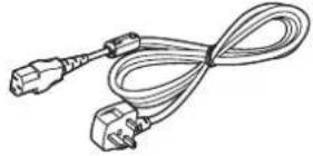 | USB cable[3.0 m, K1HB04FD0002 x1] | Lens cover[TKKL5103 x1] |
Power cord for Continental[TXFSX02VTFZ x11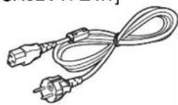 | Wired cable for remote control[15 m, K1EA03NA0001 x1] | Battery for remote control unit[R03NPE/2ST x1] | |
Right-side exhaust gui-+-[TPAKK21 x1]  Left-side exhaust guide[TPAKK22 x1]Fixing pin[TPAMM33 x1][IMAGE] Left-side exhaust guide[TPAKK22 x1]Fixing pin[TPAMM33 x1][IMAGE] | RGB signal cable (for VGA)[3.0 mK1HB | Conversion plug[K2RB031D0001 x1] |
Cautions regarding transportation
Be sure to attach the lens cover before transporting the projector.
The projection lens is extremely susceptible to vibration and shocks. When carrying the projector, be careful not to subject to excessive vibration or shock while under transport.
Cautions regarding setting-up
Observe the following at all times when setting up the projector.
Avoid setting up in places which are subject to vibration or shocks.
If the projector is set up in locations with strong vibration, such as near a motor, or if it is installed inside a vehicle or on board a ship, the projector may be subjected to vibration or shocks which can damage the internal parts and cause malfunctions or accidents. Accordingly, set up the projector in a place which is free from such vibrations and shocks.
Do not set up the projector near high-voltage power lines or near motors.
The projector may be subject to electromagnetic interference if it is set up near high-voltage power lines or motors.
If installing the projector to the ceiling, ask a qualified technician to carry out all installation work.
If the projector is to be suspended from the ceiling, you will need to purchase the separate installation kit (Model No.: ET-PKL6500/S). Furthermore, all installation work should only be carried out by a qualified technician.
This product cannot be used at altitudes of 1,400 m or more above sea level. If it is used as is, there may be an adverse effect on component service life and so on.
Notes on use
If using this projector more than 8 hours/day (continuous operation), special measures will be necessary to use this projector. Please consult your dealer or Authorized Service Centre about preparations.
In order to get the best picture quality
If outside light or light from indoor lamps is shining onto the screen, the images projected will not have good contrast. Draw curtains or blinds over any windows and turn off any fluorescent lights near the screen to prevent reflection.
Depending on the environment where used, hot air from the cooling fan vent may in rare cases cause disturbances on the screen.
Do not touch the surfaces of the lens with your bare hands.
If the surface of the lens becomes dirty from fingerprints or anything else, this will be magnified and projected onto
the screen. Moreover, when not using the projector, cover it with the accessory lens cover.
About the screen
If the screen you are using is dirty, damaged or discolored, attractive projections cannot be obtained. Do not apply any volatile substances to the screen, and do not let it become dirty or damaged.
Lamp
A mercury lamp with high internal pressure is used as the light source for this equipment. High-pressure mercury lamps have the following characteristics.
- If the lamp deteriorates due to shock, scratching or the passage of time during use, it may rupture with a loud noise, or enter the unlit state and end its service life.
- Service life varies significantly due to individual lamp differences and use conditions.
- Exceeding the replacement period will increase the probability of rupture.
About the liquid crystal panel
The liquid crystal panel of the projector is built with very high precision technology giving you fine picture details. Occasionally, a few non-active pixels may appear on the screen as a fixed point of blue, green or red.
Please note that this dose not affect the performance of your LCD.
About optical parts
If the projector is subjected to a continuous use for more than 6 hours every day, you may have to replace optical parts, such as LCD panels or polarizers within less than one year. When you use the projector in such a case, ask your dealer or an Authorized Service Center for details.
Before carrying out cleaning and maintenance, be sure to disconnect the power cord plug from the wall outlet.
Wipe the cabinet with a soft, dry cloth.
If the cabinet is particularly dirty, soak the cloth in water with a small amount of neutral detergent in it, squeeze the cloth very well, and then wipe the cabinet. After cleaning, wipe the cabinet dry with a dry cloth.
If using a chemically-treated cloth, read the instructions supplied with the cloth before use.
Do not wipe the lens with a cloth that is dusty or which produces lint.
If any dust or lint gets onto the lens, such dust or lint will be magnified and projected onto the screen. Use a blower to clean any dust and lint from the lens surface, or use a soft cloth to wipe off any dust or lint.
Example of System up
The projector features a wealth of interface ports and optional parts that can be used to set up the projection system in diverse ways. The following presents some of those setup examples:
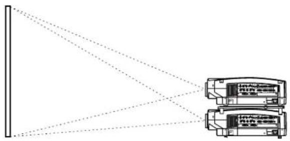
System 1
Picture brightness can be doubled by stacking two projectors with the stacking brackets.
flowchart
graph TD
    A["Central Processing Unit"] --> B["Server 1"]
    A --> C["Server 2"]
    B --> D["Data Bus"]
    C --> D
    D --> E["Output"]
    style A fill:#f9f,stroke:#333
    style B fill:#ccf,stroke:#333
    style C fill:#ccf,stroke:#333
(It is an image figure using the simple mount bracket)

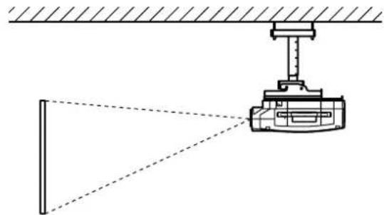
System 2
The optional high- or low-ceiling mount bracket flexibly fits the projector in individual site conditions.
natural_image
Diagram of a surveying instrument with beam path and alignment lines (no text or symbols)(It is an image figure using the Ceiling mount bracket)

System 3
PCs equipped with a DVI-D port can be attached to the projector for computer image viewing. (Realization of high clear picture.)

natural_image
Line drawing of a desktop computer setup with monitor, tower, keyboard, and projector (no text or symbols)
natural_image
Illustration of a classroom scene with students and a teacher, featuring a large screen displaying charts (no text or symbols visible)System 4
A variety of video sources can be fed to the projector through a system switcher.

flowchart
graph TD
    A["Digital STB or DVD player"] --> B["System Switcher (Option)"]
    C["Video deck"] --> B
    D["Laser disc player"] --> B
    B --> E["Control PC"]
natural_image
Line drawing of a group of children observing a framed picture on a wall (no text or symbols)Location and function of each part
Remote Control

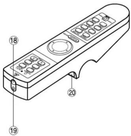
① Remote control operating indicator lamp
The light flashes when any remote control button other than the "LASER" button is pressed.
② POWER button (page 23)
Turns the projector ON/OFF when the MAIN POWER switch on the projector is set to "I".
③ AUTO SETUP button (page 23)
Pressing this button automatically corrects picture positioning on the screen. While the auto setup feature is active, the message "AUTO SETUP" appears on the screen.
④ RGB button (page 23)
Use to toggle through the RGB1, RGB2, and DVI-D input ports.
⑤ LASER button (page 15)
While this button is pressed and held, the remote control activates its laser transmitter to display a laser pointer on the screen.
⑥ VIDEO button (page 16 and 23)
Use to toggle between the Composite Video and S-Video ports. The button acts as the Page Down button if the Mode switch 1s set to the Computer position.
⑦ MENU button (pages 16, 27 and 28)
Main Menu display is switched on and off alternately each time this button is pressed. If the menu has multiple pages, this button may be used to view the next or previous menu page. The button acts as the Page Up button if the Mode switch 16s set to the Computer position.
⑧ Arrow ( ▲) Buttons (page 16 and 28)
Use to choose menu items, change settings, or adjust control parameters. The button acts as a mouse, so can move the cursor if the Mode switch 16s set to the Computer position.
⑨ ENTER button (page 16 and 28)
Press this button to enter your menu selection or to run functions. The button acts as the right mouse button if the Mode switch 16s set to the Computer position.
⑩ FREEZE button (page 25)
Press this button to temporarily freeze the image presently on the screen.
⑪ SHUTTER button (page 25)
Press this button to temporarily mute/black out both audio and video.
⑫ D.ZOOM (+/-) buttons (page 26)
Any portion of the picture can be enlarged.
⑬ VOLUME (+/-) buttons (page 23)
Use these buttons to adjust the volume level from the internal speakers or line levels on the AUDIO OUT lines.
⑭ FUNC1 button (page 35)
Use to select from the functions listed on the "OPTION 2" screen that can be chosen from the MAIN MENU.
⑮ ID SET button (page 15)
Use to set the projector ID when multiple PT-L6510E/L6600E projectors are used in the system.
⑯ Mode switch (Computer/Projector) (page 16)
When controlling the projector, set this switch to the Projector (right) side. When controlling your PC, set it to the Computer (left) side.
⑰ Wired Remote Control port (page 17)
When using wired remote control, connect the remote control to the projector with the accessory wired remote control cable.
⑱ Remote Control Transmitter Window
Whenever operating the Remote Control, aim this window to the projector's remote control receiver window.
⑲ Laser Transmitter Window
⑳ Click button (page 16)
The button acts as the left mouse button if the Mode switch 16s set to the Computer position.
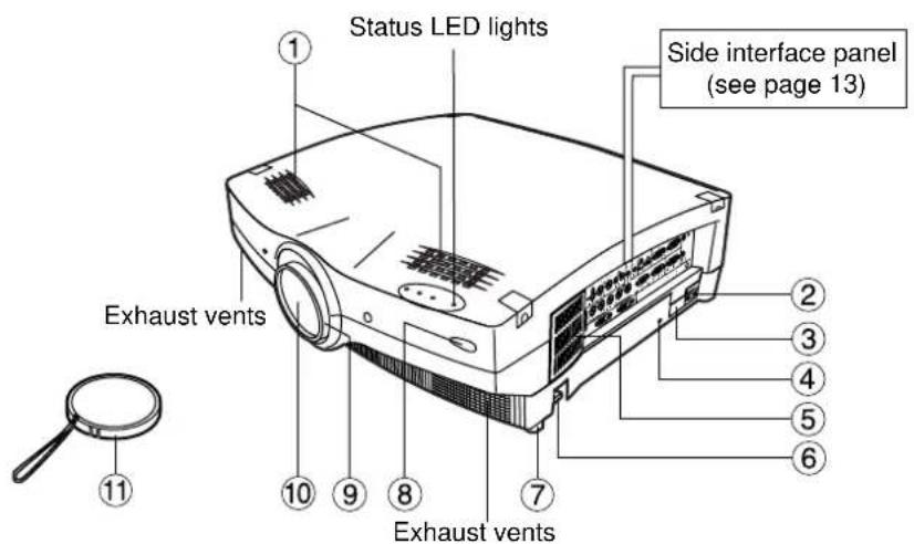
Projector < Top · Front and Side >
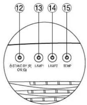
Status LED lights
(Viewed from the rear side)
① Speakers
Speakers deliver a total audio output power of 6 watts (3 + 3 watts each).
② Line input (AC IN) socket (page 23)
Connect the accessory line power cord into this receptacle. Do not connect any other cord to this socket.
③ MAIN POWER switch (page 23)
Use this switch to turn "I" "O" the commercial line power applied to the projector.
④ Burglar lock
Attach a commercial burglar prevention cable (e.g. from Kensington) to this lock port. It is compatible with the Micro Saver Security System from Kensington. This security lock is compatible with the Microsaver Security System from Kensington. Contact details for this company are given below. Kensington Technology Group ACCO Brands Inc.
2885 Campus Drive San Mateo, CA 94403
Tel (650)572-2700
Fax (650)572-9675
http://www.kensington.com/
http://www.gravis.com/
⑤ Air filter (page 41)
⑥ Leveling button (page 24)
Use these buttons (one on each side) to level the projector when resting on its feet.
⑦ Leveling foot (page 24)
Use in conjunction with ⑥ for the projector's tilt adjustment.
(A leveling foot is provided on each side of the unit.)
⑧ Remote control receiver window (page 14)
Receives IR commands transmitted from the remote control.
⑨ Focus ring (page 23)
For focus adjustment.
Powered focus adjustment is also available.
⑩ Projection lens
Images are projected onto the screen through this lens.
⑪ Lens cap
Cap the lens whenever the projector is left unused.
⑫ Power status light (page 23)
Lit in red when the projector is in standby mode with MAIN POWER switch set to "I". Lit in green when the unit is turned ON.
⑬ Lamp 1 monitor (page 40)
Lights when lamp unit 1 requires replacement. Flashes if the lamp 1 drive circuit is malfunctioning.
⑭ Lamp 2 monitor (page 40)
Lights when lamp unit 2 requires replacement. Flashes if the lamp 2 drive circuit is malfunctioning.
⑮ Temperature (TEMP) monitor light (page 40)
Warns of unacceptable internal temperatures. May be either continuously lit or flashing.
Projector < Top · Rear and Side >

How to open panel lid
Press the ▲ mark on the upper right corner of the panel lid until it clicks open.
< Rear control panel >
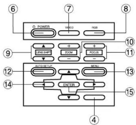
① Stack Lid
When two projectors are to be stacked, use this lid for positioning.
② Carrying handle
Pull out this handle to carry the unit.
③ Lamp unit compartment (page 43)
Houses the lamp unit.
④ Rear side remote control receiver window (page 14)
Receives commands transmitted from the remote control.
⑤ Control subpanel lid
Open this lid to access the control subpanel.
⑥ POWER switch (page 23)
Turns the unit ON/OFF.
⑦ VIDEO button (page 23)
Use to select video signal format from composite video and S-video.
⑧ RGB button (page 23)
Use to select RGB signal source from those connected to the RGB1, RGB2 and DVI ports.
⑨ LENS SHIFT buttons (page 24)
Pressing the ▲ or button tilts the projection lens to move the picture on the screen up or down accordingly.
⑩ ZOOM buttons (page 23)
Adjust the picture size on the screen with the “ + ” or “ - ” buttons.
⑪ FOCUS buttons (page 23)
Adjust focus with the “+” or “-” buttons.
⑫ AUTO SETUP button (page 23)
Pressing this button automatically corrects picture positioning on the screen. While the Auto setup feature is active, the message "AUTO SETUP" appears on the screen.
⑬ MENU button (pages 27 and 28)
Main Menu display is switched on and off alternately each time this button is pressed. If the menu has multiple pages, this button can be used to view the next or previous menu page.
⑭ ARROW (▲) button▶(page 28)
Use to choose menu items, change settings, or adjust control parameters.
⑮ ENTER button (page 28)
Press this button to enter your menu selection or to run functions.
< Interface panel >

① S-VIDEO IN port (pages 19, 20 and 33)
Connect an S-video signal source to this port.
Depend on input signal, screen aspect will automatically change 16:9 or 4:3.
② VIDEO IN port (pages 20 and 22)
Connect a composite video signal source to this port. (BNC)
③ VIDEO OUT port (pages 20 and 22)
Composite video signal appears at this port. (BNC)
④ AUDIO IN L-R jacks (page 20)
Only a single pair of audio inputs is available. Change connections to these jacks according to your choice of video source from composite and S-video (RCA jacks).
⑤ RGB AUDIO IN jack (pages 20 and 21)
Only a single pair of audio inputs is available. Change connections to these jacks according to your choice of video source from RGB1, RGB2 and DVI-D (M3 jacks).
⑥ AUDIO OUT jack (page 20)
The audio signals applied to the AUDIO IN or RGB AUDIO IN jacks of this unit appear at this jack. Once a cable is plugged into this jack, the signal lines to the internal speakers are cut off. (M3 jack)
⑦ USB IN ports (pages 16, 21 and 38)
The remote control can be used as your PC mouse by connecting the projector to your PC with the supplied USB cable. (4-pin square connector)
⑧ USB OUT ports
The control ports on two or more projectors can be connected to each other for interlocked control operations. (Type B)
⑨ SERIAL IN port (pages 20, 21, 22 and 37)
Use the RS-232C serial port as an alternative interface for controlling the projector from your PC. (D-SUB 9 pin)
⑩ SERIAL OUT port (pages 21 and 22)
The signal applied to the serial input port appears at this port (9-pin D-sub female connector).
⑪ RGB1 (YP _B PR) input ports (pages 20, 21 and 22)
Apply RGB or YP B P R video to these ports. (BNC)
⑫ RGB2 (YP _B PR) IN port (page 21)
RGB video input port. (D-SUB 15 pin)
⑬ RGB OUT port (pages 21 and 22)
The signals applied to RGB1 or RGB2 input ports appear at this port (15-pin D-sub female connector).
⑭ REMOTE port (page 39)
This port may be used to control the projector from the Remote Control set up in Wired mode. (9-pin D-sub female connector)
⑮ DVI-D IN port (pages 19 and 21)
DVI-D signals are applied to this port. (24-pin DVI connector)
⑯ DVI-D OUT port (page 21)
The signal applied to the DVI-D input port appears at this port (24-pin DVI connector).
⑰ WIRED IN/OUT ports (page 17)
Use to connect multiple PT-L6510E/L6600E projectors in a daisy chain to simultaneously control them from a single wired remote control. (M3 jack)
Using the Remote control unit
■ Loading batteries
When loading batteries into the battery compartment of the remote control, make sure that their polarities are correct.
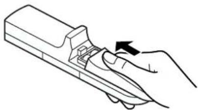
1. Open battery compartment lid.
Open lid in the order of steps ① and . ②

2. Insert the batteries
Into battery compartment, with their polarities orientated as indicated (④) in the compartment.

3. Close battery compartment lid.
Replace the battery compartment lid over the compartment and slide until it clicks.
natural_image
Line drawing of a hand holding a tool with an arrow indicating rotation (no text or symbols)Caution
• Exercise care not to drop the remote control on hard flooring.
• Exercise care not to spill water or any other liquid on the remote control.
- Do not use Ni-Cd batteries with this remote control.
■ Effective control range
The remote control should normally be aimed at either the front or rear remote control receiver window on the projector (fig. 1). Otherwise it may also be aimed at the screen, which will reflect commands back to the projector's front receiver window as illustrated in figure 2.
The effective control range is approx. 7 metres (23 feet) immediately in front of the receiver windows.
![(Front) Remote control 30° 30° (Rear) [Top view] 30° 30° Remote control Remote control 15° 15° [Side view] 15° 15° Remote control](/content/2026/06/1203271/images/549de7f241c9c652dac5a721b9426fb55256ea9e362ef83f45aedbf64c3db9d9.jpg)
fig. 1

fig. 2
Note
- When the remote control is aimed at the screen, the effective control range may be reduced due to the optical loss of the screen.
- The remote control may not function properly if an object is in the light path.
- The remote control receiver may not function properly in intense ambient light. Carefully site the projector so its remote control receiver windows will not be directly exposed to intense light.
■ Using laser pointer
The remote control contains a laser source that can appear as a coloured spot on the screen which you can use as a pointer. The laser beam is activated while the "LASER" button is pressed and held.

Laser Transmitter Window
Warning
DO NOT STARE INTO THE LASER BEAM OR AIM IT AT ANY PERSON'S EYE. LASER RADIATION CAN CAUSE SERIOUS INJURY TO THE HUMAN EYE.
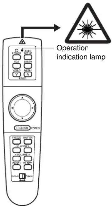

Laser Specifications:
Wavelength: 640 to 660 nm
Output power: 1 mW (Class 2)
Caution
- Use of controls or adjustments or performance of procedures other than those specified herein may result in hazardous radiation exposure.
- This remote control unit cannot be repaired.
■ Setting projector IDs for remote control
When controlling multiple projectors individually or simultaneously with a single remote control, projector IDs must be set into the remote control as described in the following steps:
- Press the "ID SET" button on remote control.
ID number "ALL" will be displayed on the OSD.
- Press and hold the "ID SET" button for more than 2 seconds.
The ID number will change into "1". The "ID SET" button will now toggle through ID numbers "2", "3", "ALL", "1", and so on each time it is subsequently pressed.
- Select the ID number you wish and then press the "ENTER" button.
Note
- The projector ID number in the remote control is set to “ALL” by default. It is therefore not necessary to set a projector ID number when only one projector is used.
- The projector can be turned ON/OFF from the remote control only if the projector ID is set in the remote control. For more details on projector ID setting, see page 36.
■ Using the remote control as a PC mouse
You can use the remote control as your PC mouse. Set the Mode (Projector/Computer) switch on the remote control to Computer and connect the projector's USB port to your PC counterpart with the accessory USB cable.
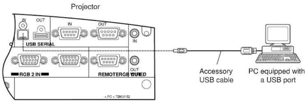
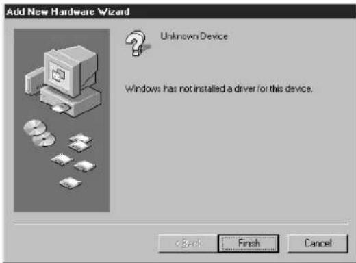
- When your PC is attached to the projector for the first time, the "new hardware wizard" will launch automatically. When USB cable connects for the first time between projector and PC, the following massage appear from PC. The reason that the driver not installed, therefore press "NEXT" button continuously and finally. Press "Finish".
The following is in the case of Windows

Note
- If you click "Cancel", the "new hardware wizard" launches each time your PC is connected to the projector.

Mode switch (Computer/Projector)
Mode switch is set to the Computer position.
- Page button
A: Functions as the Page Up button on your PC keyboard.
V: Functions as the Page Down button on your PC keyboard.
- Arrow (▲) button
These buttons functions as the cursor control buttons on your PC.
- R-CLICK button
This button functions as the right button on your PC mouse.
- Click button
This button functions as the left button on your PC mouse.
Note
- The optional wireless receiver (Model ET-RMRC1) is needed for a PC not equipped with a USB port. However, Page buttons do not function.
■ Using the remote control in wired mode
Two or more projectors can be controlled from a single Remote Control by connecting the Remote Control to the projectors with the accessory Wired Remote Control Cable. The wired remote control is particularly useful if the projector is sited in a place where it is exposed to intense ambient light or if an object blocks the path of IR light from the Remote Control.

■ Projection Schemes
Any of the following four projection schemes can be used with the PT-L6510E/L6600E projector depending on user's needs or viewing conditions. Use "OPTION 1" menu (chosen from the MAIN MENU) to choose the appropriate projection scheme (see page 34).
| Projection Scheme 2 | |||
| Table standing | Ceiling mount | ||
| Projection Scheme 1 | Front projection |  |  |
| Rear projection |  |  | |
■ Installation Geometry
After the projector is roughly positioned, picture size and vertical picture positioning can be finely adjusted with the powered zoom lens and lens tilt mechanism.
Side view

L: Projection distance
SH: Image height
SW: Image width
H: Distance from centre of lens to bottom edge of projected image.
Top view

[unit : mm]
■ Projection Distances
Unit : m
| Screen Size (4 : 3) | Projection distance: L | Height position: H | |||
| Diagonal length | Height (SH) | Width (SW) Wide (LW) | |||
| 0.76 | 0.46 | 0.61 | — | 1.4 | 0.02 to 0.22 |
| 1.02 | 0.61 | 0.81 | 1.4 | 1.9 | 0.03 to 0.30 |
| 1.27 | 0.76 | 1.02 | 1.8 | 2.4 | 0.04 to 0.38 |
| 1.52 | 0.91 | 1.22 | 2.1 | 2.9 | 0.05 to 0.45 |
| 2.03 | 1.22 | 1.63 | 2.9 | 3.9 | 0.06 to 0.60 |
| 2.54 | 1.52 | 2.03 | 3.6 | 4.9 | 0.08 to 0.76 |
| 3.05 | 1.83 | 2.44 | 4.3 | 5.9 | 0.09 to 0.91 |
| 3.56 | 2.13 | 2.84 | 5.1 | 6.9 | 0.11 to 1.06 |
| 4.06 | 2.44 | 3.25 | 5.8 | 7.9 | 0.12 to 1.21 |
| 4.57 | 2.75 | 3.66 | 6.6 | 8.9 | 0.14 to 1.37 |
| 5.08 | 3.05 | 4.06 | 7.3 | 9.9 | 0.15 to 1.52 |
| 5.51 | 3.35 | 4.47 | 8.1 | 10.9 | 0.17 to 1.67 |
| 6.10 | 3.66 | 4.88 | 8.8 | 11.9 | 0.18 to 1.82 |
| 6.60 | 3.96 | 5.28 | 9.5 | 12.9 | 0.20 to 1.98 |
| 7.11 | 4.27 | 5.69 | 10.3 | 13.9 | 0.21 to 2.13 |
| 7.62 | 4.57 | 6.10 | 11.0 | 14.9 | 0.23 to 2.28 |
Setting-up dimensions which are not given in the above table can be calculated using the formulas below.
If the screen size (diagonal) is SD, then the following formulas is first used to obtain the screen width (SW).
$$ \mathrm{SW} = (\mathrm{SD} \times 0. 0 2 5 4) \times 4 \mid 5 \quad (\text { SD unit is inches }) $$
The value for SW obtained above can then be used with the following function to calculate the projection distance for the wide lens position (LW) and the projection distance for the telephoto lens position (LT).
$$ \mathrm{LW} = 1. 8 3 1 \times \mathrm{SW} - 0. 0 7 1 $$
$$ \mathrm{LT} = 2. 4 4 9 \times \mathrm{SW} - 0. 0 6 6 $$
For 16 : 9 aspect rations, the following formal can be used to calculate the screen width (SW).
$$ \mathrm{SW} = (\mathrm{SD} \times 0. 0 2 5 4) \times 1 6 \mid \sqrt {3 2 7} $$
Note
- The dimensions in the table above and the values obtained from the above formulas may contain slight errors.
- It is recommended that you use the projection distance for the wide lens position (except in cases where the diagonal picture size is 0.762 m).
- The above dimensions are the case when the aspect ratio is 4:3. When an SXGA signal is input and projected, the right and left ends of the picture will be blanked the aspect ratio will be 5:4.
■ Setup precautions
- Before connecting any of your video/audio equipment to the projector, carefully read the owners manual supplied with the equipment once again.
- All cable connections should be made with the entire system devices, including the projector, first turned off.
- Obtain commercial interconnecting cables for devices supplied with no accessory or optional interconnect cables.
- Video signals containing too much jitter may cause the images on the screen to randomly wobble or shake. Inserting a time base corrector (TBC) in the projector's video line will relieve this problem.
- The projector only accepts composite-video, S-video, analogue-RGB (with TTL sync. level), and digital signal from PC.
- The projector contains built-in speakers. When greater sound output is required, use an audio amplifier connected to the projector's AUDIO OUT jack. Once the cable is plugged into the AUDIO OUT jack, the audio signal lines to the internal speakers are automatically cut off.
- Some PC models are not compatible with the PT-L6510E/L6600E projector.
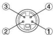
- The pin assignments on the S-VIDEO IN port are as follows:
Viewed from mating side
| Pin No. | Signal |
| 1 | Ground (luminance) |
| 2 | Ground (colour) |
| 3 | Luminance signal |
| 4 | Colour signal |
- The pin assignments on the RGB2 input port are as follows:

Viewed from mating side
| Pin No. | Signal |
| 1 | R/PR |
| 2 | G/G · SYNC/Y |
| 3 | PB |
| 12 | SDA |
| 13 | HD/SYNC |
| 14 | VD |
| 15 | SCL |
Pin 9Not used.
Pins ④, 8and: Ground.
Pins 12 and : Valid if the PC has the corresponding function.
- The pin assignments on the DVI-D input port are as follows (interface with TMDS port on PC):

Viewed from mating side
| Pin No. | Signal | Pin No. | Signal |
| 1 | T. M. D. S data 2- | 13 | T. M. D. S data 3+ |
| 2 | T. M. D. S data 2+ | 14 | +5 V |
| 3 | T. M. D. S data 2/4 shield | 15 | Ground |
| 16 | Hot plug sense | ||
| 4 | T. M. D. S data 4- | 17 | T. M. D. S data 0- |
| 5 | T. M. D. S data 4+ | 18 | T. M. D. S data 0+ |
| 6 | DDC clock | 19 | T. M. D. S data 0/5 shield |
| 7 | DDC data | ||
| 8 | —— | 20 | T. M. D. S data 5- |
| 9 | T. M. D. S data 1- | 21 | T. M. D. S data 5+ |
| 10 | T. M. D. S data 1+ | 22 | T. M. D. S clock shield |
| 11 | T. M. D. S data 1/3 shield | ||
| 23 | T. M. D. S clock+ | ||
| 12 | T. M. D. S data 3- | 24 | T. M. D. S clock- |
■ Example of connecting with AV products

flowchart
graph TD
    A["Colour monitor"] --> B["Laser disc player"]
    B --> C["Video deck"]
    C --> D["Control PC"]
    D --> E["Audio equipment"]
    E --> F["Digital Hi-vision video deck"]
    F --> G["Red (Connect P_R)"]
    F --> H["Blue (Connect P_B)"]
    F --> I["Green (Connect Y)"]
    B --> J["RGB AUDIO"]
    B --> K["USB SERIALS-VIDEO IN AUDIO IN"]
    C --> L["RGB 2 IN"]
    C --> M["OUTIN"]
    C --> N["REMO TERS"]
    C --> O["OUT"]
    style A fill:#f9f,stroke:#333
    style B fill:#ccf,stroke:#333
    style C fill:#cfc,stroke:#333
    style D fill:#fcc,stroke:#333
    style E fill:#cff,stroke:#333
    style F fill:#ffc,stroke:#333
    style G fill:#cfc,stroke:#333
    style H fill:#cfc,stroke:#333
    style I fill:#cfc,stroke:#333
    style J fill:#fcc,stroke:#333
    style K fill:#fcc,stroke:#333
    style L fill:#fcc,stroke:#333
    style M fill:#fcc,stroke:#333
    style N fill:#fcc,stroke:#333
    style O fill:#fcc,stroke:#333
Note
- Only a single pair of audio inputs (AUDIO IN L-R) is available for the composite and S video, also only a signal RGB audio input is available for the RGB1, RGB2 and DVI-D. You will need to change audio input connections depending on your signal selection.
- If your audio equipment is connected to the projector's AUDIO OUT jack, the remote control supplied with the projector can be used to control volume, balance, and mute on the audio output line.
■ Example of connecting with PCs

flowchart
graph TD
    A["PC with DVI port"] --> B["DVI Cable (Option) (ET-SCDV03)"]
    B --> C["PC with USB port"]
    C --> D["USB cable (Accessory)"]
    D --> E["PC Control PC"]
    E --> F["Colour monitor with RGB video ports"]
    F --> G["Color monitor with RGB video ports"]

    subgraph Video
        H["VIDEO"] --> I["RGB 1 IN"]
        J["IN OUT"] --> K["AUDIO"]
        L["USB SERIALS-VIDEO IN AUDIO IN"] --> M["RGB 2 IN"]
        N["OUTIN"] --> O["REMO TERS"]
        P["IN"] --> Q["OUT"]
    end

    subgraph Audio
        R["RGB 1 IN"] --> S["RGB 2 IN"]
        T["IN OUT"] --> U["AUDIO"]
        V["USB SERIALS-VIDEO IN AUDIO IN"] --> W["RGB 2 IN"]
        X["OUTIN"] --> Y["REMO TERS"]
        Z["IN"] --> AA["OUT"]
    end

    subgraph Wire
        AB["DVI-D OUTIN"] --> AC["Outin"]
        AD["*1"] --> AE["Outin"]
    end

    style Video fill:#f9f,stroke:#333
    style Audio fill:#ccf,stroke:#333
    style Wire fill:#cfc,stroke:#333
Caution
- When the projector's main power is turned OFF, also turn OFF all the PCs connected to it.
- *1 An asterisk denotes that the second projector requires positioning if the RGB outputs are connected in a daisy chain. However, the signals should be divided at the signal source if possible.
Note
- If your PC is not equipped with a USB port, a ET-RMRC1 interface will be needed to use the mouse capability of the remote control.
- For the specifications of the RGB signals that can be applied from the PC, see the data sheet on page 48.
- If your PC has the resume feature, the computer may not function properly until the resume capability is disabled.
- Signals applied to the RGB1 or RGB2 ports appear at the RGB OUT port.
■ Example of connecting with system switcher
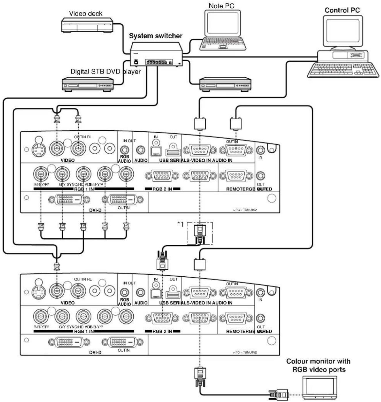
flowchart
graph TD
    A["Video deck"] --> B["System switcher"]
    C["Note PC"] --> B
    D["Control PC"] --> B
    E["Digital STB DVD player"] --> B
    B --> F["VIDEO"]
    B --> G["USB SERIALS-VIDEO IN AUDIO IN"]
    B --> H["REMO TERGB OUTED"]
    F --> I["OUTIN RL"]
    G --> J["IN OUT"]
    H --> K["IN OUT"]
    I --> L["RGB AUDIO"]
    J --> M["RGB 2 IN"]
    K --> N["RGB 1 IN"]
    L --> O["DVI-D"]
    M --> P["OUTIN"]
    N --> Q["*1"]
    O --> R["DVI-D"]
    P --> S["OUTIN RL"]
    Q --> T["IN OUT"]
    R --> U["RGB AUDIO"]
    S --> V["USB SERIALS-VIDEO IN AUDIO IN"]
    T --> W["IN OUT"]
    U --> X["RGB 2 IN"]
    V --> Y["REMO TERGB OUTED"]
    W --> Z["OUTIN RL"]
    X --> AA["IN OUT"]
    Y --> AB["OUTIN RL"]
    Z --> AC["DVI-D"]
    AA --> AD["OUTIN RL"]
    AB --> AE["IN OUT"]
    AC --> AF["DVI-D"]
    AD --> AG["OUTIN RL"]
    AE --> AH["IN OUT"]
    AF --> AI["OUTIN RL"]
    AG --> AJ["DVI-D"]
    AH --> AK["OUTIN RL"]
    AI --> AL["IN OUT"]
    AJ --> AM["DVI-D"]
    AK --> AN["OUTIN RL"]
    AL --> AO["DVI-D"]
    AM --> AP["OUTIN RL"]
    AN --> AQ["DVI-D"]
    AO --> AR["OUTIN RL"]
    AP --> AS["DVI-D"]
    AQ --> AT["OUTIN RL"]
    AR --> AU["DVI-D"]
    AS --> AV["OUTIN RL"]
    AT --> AW["DVI-D"]
    AU --> AX["OUTIN RL"]
    AV --> AY["DVI-D"]
    AW --> AZ["OUTIN RL"]
    AX --> BA["DVI-D"]
Caution
- *1 An asterisk denotes that the second projector requires positioning if the RGB outputs are connected in a daisy chain. However, the signals should be divided at the signal source if possible.
Note
- Read the operating instructions for the system switcher carefully.

■ Powering Up the Projector
① Remove the lens cover.
② Plug one end of the accessory power cord into the projector's power receptacle, and the other end to a convenient wall outlet. (AC 220-240 V 50Hz/60 Hz)
③ Press the “I” marked side of the MAIN POWER switch.
The projector will enter standby mode, with the power status light lit in red.
④ Press the "POWER" button on the projector or "POWER" button on the remote control.
The power indicator on the projector will flash orange. After a shot period, the indicator will illuminate green.
■ Making Initial Adjustment / Setting input port
⑤ Roughly adjust the focus with the "FOCUS (+/-)" buttons on the rear control panel or with focus ring on the projection lens.
⑥ Choose the projection scheme (page 34).
⑦ Select the input port with the "RGB" or "VIDEO" button. --- [Projector or remote control]
| RGB | RGB1(YP_BPR1) RGB2(YP_BPR2) DVI |
| VIDEO | S-VIDEO ↔ VIDEO |
⑧ Adjust volume level with the "VOLUME (+/-)" buttons. --- [Remote control]
For volume level control on the projector, see page 27. If your audio equipment is connected to the AUDIO OUT jack, the VOLUME control adjusts the line output level.
⑨ Adjust the projector's tilt angle (page 24).
⑩ Adjust the vertical position of the picture (page 24)
⑪ Press the "AUTO SETUP" button --- [Projector or remote control]
⑫ Fit the picture size to the screen size--- [Projector] Fit the picture size to the screen size with the "ZOOM (+/-)" buttons on the projector's rear control panel. Repeat steps ⑨ through ⑩ until the picture completely fits within the screen bounds.
⑬ Adjust focus again with the "FOCUS (+/-)" buttons on the rear control panel or with the focus ring on the projection lens.
⑭ Adjust the "ZOOM (+/-)" buttons again until the picture completely fits within the screen bounds.
■ Powering Off the Projector
- Press and hold the "POWER" button for more than 0.5 seconds or quickly double-press the button. The projection lamp will turn off, with the power status light turned to orange.
- Wait until the power status light turns to red (i.e., until the cooling fan stops). While the cooling fan is still running, never switch the MAIN POWER switch OFF, unplug the projector from the outlet, or open the main circuit breaker.
- Press the "O" marked side of the MAIN POWER switch to remove all power from the projector.
Note
- If the projector is re-powered while the projection lamps are cooling down after the last power off, the lamps will remain off for a short time before they automatically turn on again (Power Status light flashing in orange).
- The projector consumes approx. 9 Watts of power in Standby mode after the cooling fan stops (Power Status light lit in red).
- If you inadvertently shut off the Main Power switch, the projection lamp may remain off for some time on re-powering the projector. The lamp will automatically turn on after a period of time (Power Status light lit in green).
■ Leveling the Projector
For the best viewing result free from distortion, the projector should be carefully leveled on its base. Follow the steps below to correct the tilt angle of the projector when it is installed on a floor-standing base.
- While lifting and holding the front side of the projector to the level position, pull and hold the LEVELING button on each side of the bottom panel until the leveling feet rest on the projector base surface.
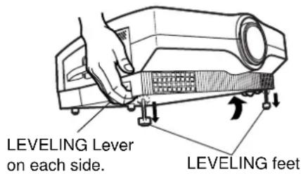
Caution
- Keep holding the projector until both leveling feet touch the base surface.
- Release the LEVELING levers.
The leveling feet lock in place.
- Make fine leveling adjustments by manually turning the leveling feet.

Note
- The maximum length of the leveling foot is 47 mm. If it is rotated on reaching that length it will turn freely without extending further.
- If the picture has keystone distortion, do keystone adjustment from the menu. (page 32)
While lifting the front side of the projector, raise the Leveling lever, and then slowly lower the unit.

natural_image
Technical line drawing of a mechanical component with mounting feet and a central circular feature (no text or symbols)Caution
- Do not press the LEVELING levers without holding the projector with your hands. Otherwise, the leveling feet will be unlocked and the projector may drop rapidly onto the projector base surface, possibly leading to damage.
■ Adjusting the Vertical Position of the Picture
The vertical position of the picture can be adjusted using the electric "LENS SHIFT" buttons on the rear control panel. Do this adjustment after the projection distance and projector position have been determined.
- Adjusting vertical position with the "LENS SHIFT" buttons:
Press the ▲ button to shift the picture upward.

natural_image
Diagram showing light rays converging through a device (no text or symbols present)Press the ▼ button to shift the picture downward.
- Adjusting vertical position from the menu: Alternatively, you can adjust the vertical position of the picture by choosing the "LENS SHIFT" option from the "OPTION 1" menu chosen from the MAIN MENU (see page 34).
Caution
When shifting the lens, be careful not to catch your fingers between the lens and shroud.
■ Advice on the installation of exhaust guides
Hot air from the cooling fan vents may in rare cases cause disturbances to the screen image. If this should occur, install the attached exhaust guides.

Left-side exhaust guide

Right-side exhaust guide

Fixing pin (2 sets)

natural_image
Technical line drawing of a projector with lens and control panel (no text or symbols)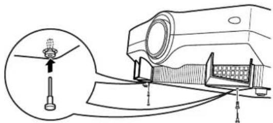
-
Identify the left-side and right-side exhaust guides, then insert the tabs of the relevant guide into the holes on the front of the projector.
-
Insert the fixing pins from the bottom of the projector and tighten them securely.
Using the Freeze function
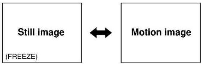
The picture freezes each time you press the remote control "FREEZE" button.
flowchart
graph LR
    A["Still image\n(FREEZE)"] <--> B["Motion image"]
Using the Shutter function
The shutter function can be used to momentarily turn off the picture and sound from the projector when the projector is not being used for short periods of time, such as during breaks in meetings or when carrying out preparation. The projector uses less power in shutter mode than it does in normal projection mode.
- Press the remote control/ "SHUTTER" button to mute both picture and sound.
Both video and audio are turned off.
- To clear muting, press any button on the remote control or projector.
Apear the picture and sound.
Using the Digital Zoom (D.ZOOM +/-) function
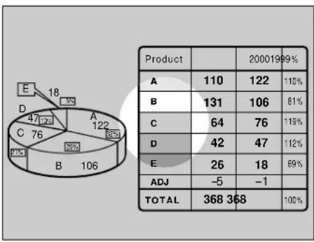
A specific portion of the picture presently on the screen can be zoomed in on with the remote control/ "D.ZOOM (+/-)" buttons. You may find it useful for highlighting a specific object during your presentation.
pie
| Product | Value | Percentage (%) | | :--- | :--- | :--- | | A | 110 | 110 | | B | 131 | 81 | | C | 64 | 119 | | D | 42 | 112 | | E | 26 | 69 | | ADJ | -5 | -1 | | TOTAL | 368 | 100 |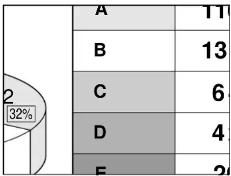
other
| Category | Value | |---|---| | A | 11 | | B | 13 | | C | 6 | | D | 4 | | E | 2 |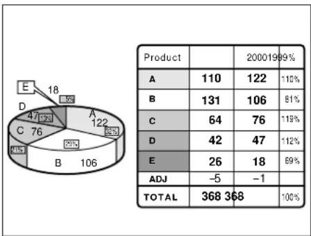
pie
| Product | Value | Percentage (%) | | :--- | :--- | :--- | | A | 110 | 110 | | B | 131 | 81 | | C | 64 | 119 | | D | 42 | 112 | | E | 26 | 69 | | ADJ | -5 | -1 | | TOTAL | 368 | 100 || A | 11 | |
| B | 13 | |
| C | 6 | |
| D | 4 | |
| E | 2 |
Caution
< For PT-L6510E >
- Press the remote control Digital Zoom (D.ZOOM +/-) buttons.
The projector enters Highlight mode as illustrated on the left.
-
Use the arrow (▲▼) buttons to highlight the portion you wish to zoom in on.
-
Press the "ENTER" button.
The highlighted portion will now be enlarged 2.0 times to the size of the full screen.
- Change the magnification with the "D.ZOOM (+/-)" buttons.
RGB signal input : Over the range of 1.0 to 3.0 times in 0.1 steps.
Video signal input : Over the range of 1.0 to 2.0 times.
- To restore the original image, press the "MENU" button.
Pressing the "MENU" button will not return the screen to Highlight mode. To return to Highlight mode, temporarily exit Zoom mode, then press the "D.ZOOM (+/-)" button again.
< For PT-L6600E >
- Press the Remote Control/"D.ZOOM +/-" button.
The centre portion of the picture will be magnified.
- Change magnification with the "D.ZOOM +/-" button:
Magnification can be changed from 1.0 to 3.0 times for RGB, and 1.0 to 2.0 times for composite or S-video, all in 0.1 steps.
- The enlarged portion of the picture can be shifted with the ▲, ▼, or buttons.
The highlighted portion will now be enlarged 2.0 times to the size of the full screen.
-
Press the "MENU" button to return to the normal picture.
-
If the input video signal format is changed while in Zoom mode, the projector will exit Zoom mode.
- PT-L6600E does not have a highlight indication.
■ Menu screens
Menus are extensively used for configuring, adjusting, or reconfiguring the projector. The menu structure is as follows:
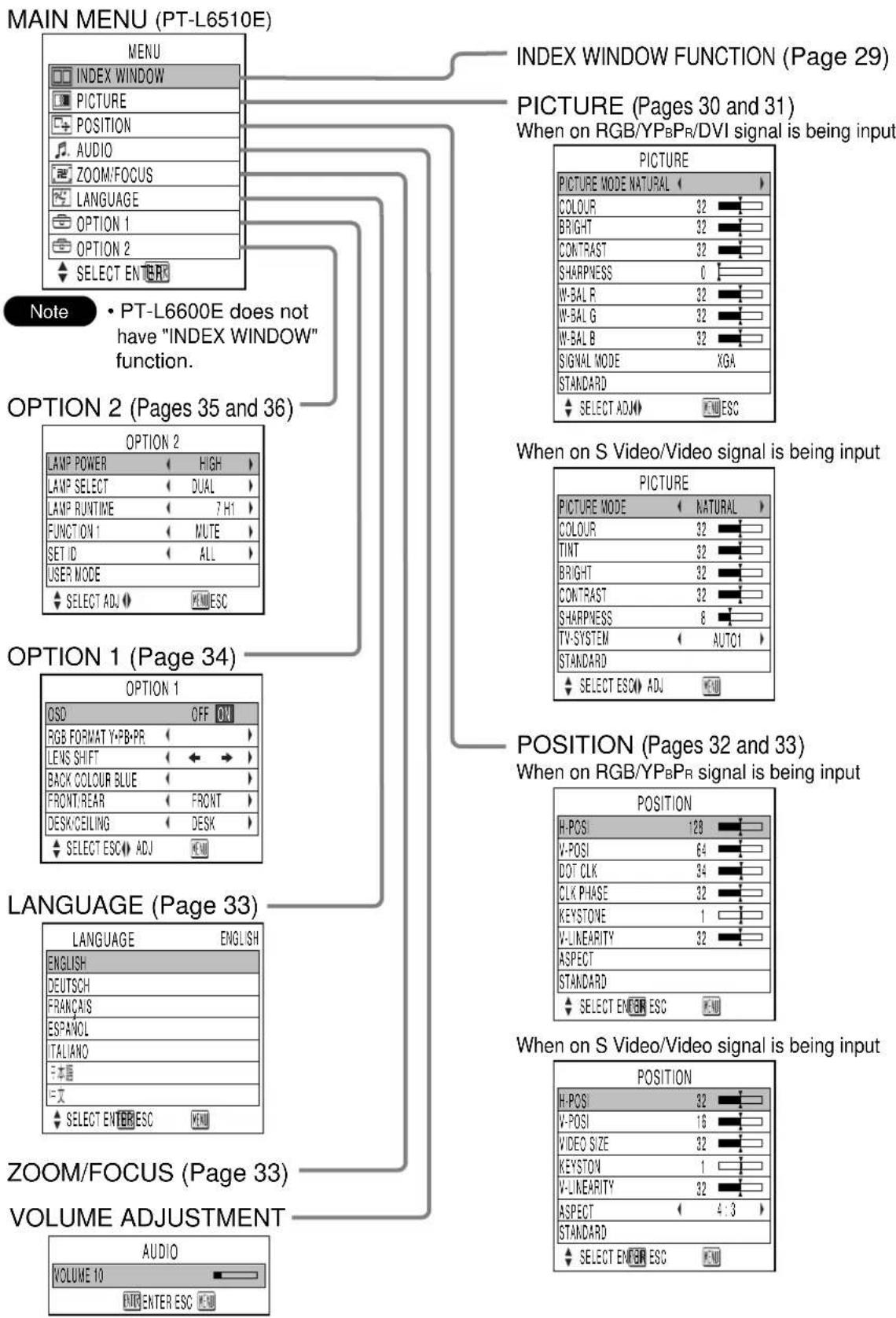
flowchart
graph TD
    A["MAIN MENU (PT-L6510E)"] --> B["INDEX WINDOW FUNCTION (Page 29)"]
    A --> C["PICTURE (Pages 30 and 31) When on RGB/YPBPR/DVI signal is being input"]
    A --> D["PICTURE MODE NATURAL"]
    D --> E["COLOUR 32"]
    D --> F["BRIGHT 32"]
    D --> G["CONTRAST 32"]
    D --> H["SHARPNESS 0"]
    D --> I["W-BAL R 32"]
    D --> J["W-BAL G 32"]
    D --> K["W-BAL B 32"]
    D --> L["SIGNAL MODE XGA"]
    D --> M["STANDARD"]
    D --> N["SELECT ADJ ESC"]
    O["NOTE"] --> P["PT-L6600E does not have "INDEX WINDOW" function."]
    Q["OPTION 2 (Pages 35 and 36)"] --> R["LAMP POWER HIGH"]
    Q --> S["LAMP SELECT DUAL"]
    Q --> T["LAMP RUNTIME 7H1"]
    Q --> U["FUNCTION 1 NUTE"]
    Q --> V["SET ID ALL"]
    Q --> W["USER MODE"]
    Q --> X["SELECT ADJ ESC"]
    Y["OPTION 1 (Page 34)"] --> Z["OSD OFF ON"]
    Y --> AA["RGB FORMAT Y-PB-PR"]
    Y --> AB["LENS SHIFT"]
    Y --> AC["BACK COLOUR BLUE"]
    Y --> AD["FRONT/REAR FRONT"]
    Y --> AE["DESK/CEILING DESK"]
    Y --> AF["SELECT ESC ADJ ESC"]
    AG["OPTION 1 (Page 34)"] --> AH["POSITION (Pages 32 and 33) When on RGB/YPBPR signal is being input"]
    AG --> AI["POSITION H-POSI 128"]
    AG --> AJ["V-POSI 64"]
    AG --> AK["DOT CLK 34"]
    AG --> AL["CLK PHASE 32"]
    AG --> AM["KEYSTONE 1"]
    AG --> AN["V-LINEARITY 32"]
    AG --> AO["ASPECT"]
    AG --> AP["STANDARD"]
    AG --> AQ["SELECT ENER ESC"]
    AR["LANGUAGE (Page 33)"] --> AS["LANGUAGE ENGLISH"]
    AR --> AT["ENGLISH DEUTSCH FRANÇAIS ESPANOL TALIANO F-本語 F-文"]
    AR --> AU["SELECT ENTER ESC"]
    AV["ZOOM/FOCUS (Page 33)"] --> AW["VOLUME ADJUSTMENT"]
    AX["AUDIO VOLUME 10"] --> AY["ENTER ESC ESC"]
Press the "ENTER" botton, and the press the ◀ and ▶ bottoms to adjust the volume level.
■ Basic Menu Operations
1. Press the "MENU" button.
The MAIN MENU appears on the screen. (e.g.: MAIN MENU for the PT-L6510E)

2. Select (highlight) the desired item with the ▲ or ▼ buttons.
Selected items are displayed in yellow.
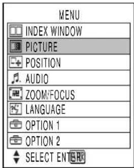
3. Press the "ENTER" button to enter your selection.
The submenu for the selected option will now open. (e.g.: PICTURE Menu)
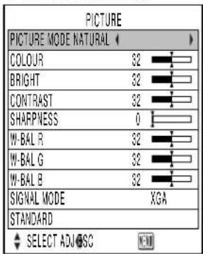
4. Highlight the desired adjustment item with the ▲ or buttons, then change the parameter value with the ◀ or buttons.
An individual bar graph as shown in the following figure is displayed for each adjustment item.

- If no button is operated for approx. 5 seconds while a bar graph is displayed, the screen will return to the previous page.
■ Returning to the Previous Page
- Pressing the "MENU" button returns the screen to the previous menu page. - When the MAIN MENU is on the screen, pressing the MENU button clears all menus from the screen.
■ Menu Items Shown with White Characters
- Some menu items may not be valid for some signal formats applied to the projector. Invalid menu items are shown in white letters and the "ENTER" button remains ineffective to those items.
■ Menu Items Setting
The bottom prompt line differs on each menu depending on the selected menu option:
- The prompt “◀▶DJ” is displayed for direct adjustment. - The prompt “ENTER” appears for a separate bar graph.
■ Reset the Factory Default
If the "STANDARD" option in the "PICTURE" or "POSITION" menus is chosen, or the "STANDARD" option in the remote control's "FUNC1" button menu is chosen, all the parameter values in the menu are reset to the factory default.
- Default Setting in Menu When all the parameter values in the menu are reset to the factory default, a "STD" indicator appears on the upper right corner of the menu.
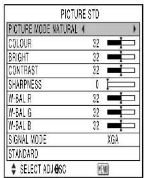
- Default Setting on Bar Graph If the parameter value on a bar graph is reset to the factory default, the bar turns to green.

Note
- The upper and lower triangular markings on a bar graph indicate the default setting for the parameter. If no such triangular markings are shown on the bar graph, the parameter cannot be reset to the factory default.

The picture presently on the screen can be saved to memory as a still image. The saved image can then be shown alongside a moving image in a split screen (index window).

flowchart
graph TD
    A["Still image ESC"] --> B["Moving image"]
    B --> C["Still image ESC"]
    C --> D["Moving image"]
    D --> E["Still image ESC"]
    E --> F["Moving image"]
    F --> G["Still image ESC"]
    G --> H["Moving image"]
    H --> I["Still image ESC"]
    I --> J["Moving image"]
    J --> K["Still image ESC"]
    K --> L["Moving image"]
    L --> M["Still image ESC"]
    M --> N["Moving image"]
    N --> O["Still image ESC"]
    O --> P["Moving image"]
    P --> Q["Still image ESC"]
    Q --> R["Moving image"]
    R --> S["Still image ESC"]
    S --> T["Moving image"]
    T --> U["Still image ESC"]
    U --> V["Moving image"]
    V --> W["Still image ESC"]
    W --> X["Moving image"]
    X --> Y["Still image ESC"]
    Y --> Z["Moving image"]
    Z --> AA["Still image ESC"]
    AA --> AB["Moving image"]
    AB --> AC["Still image ESC"]
    AC --> AD["Moving image"]
    AD --> AE["Still image ESC"]
    AE --> AF["Moving image"]
    AF --> AG["Still image ESC"]
    AG --> AH["Moving image"]
    AH --> AI["Still image ESC"]
    AI --> AJ["Moving image"]
    AJ --> AK["Still image ESC"]
    AK --> AL["Moving image"]
    AL --> AM["Still image ESC"]
    AM --> AN["Moving image"]
    AN --> AO["Still image ESC"]
    AO --> AP["Moving image"]
    AP --> AQ["Still image ESC"]
    AQ --> AR["Moving image"]
    AR --> AS["Still image ESC"]
    AS --> AT["Moving image"]
    AT --> AU["Still image ESC"]
    AU --> AV["Moving image"]
    AV --> AW["Still image ESC"]
    AW --> AX["Moving image"]
    AX --> AY["Still image ESC"]
Note
- The aspect ratio of each half of the split screen is 2:3, with the image height extended by 1.5 times the normal height by default.
- Select the "INDEX WINDOW" from menu and press the "ENTER" button.
- Change the picture height with the ▲or ▼ button.
- The picture height can be changed at a magnification of x1, x1.5, or x2.0 times.
- The still and motion images can be swapped with the ◀ or button.
- Press the "ENTER" button to save the split screen image to memory as an index window image.
Caution
- As you change the screen size, the aspect ratio of the picture also changes. Carefully read the caution for S1 signals on page 33 before changing the screen size.
Note
- When you execute steps 2 and 3 above, the memory is temporarily cleared and the index window image is saved to memory.
-
If the input signal format is changed while an index window is on the screen, the projector will exit the index window mode.
-
Obtain the MENU window and select (highlight) the desired option item with the ▲ or buttons.
- Adjust the parameter value with the ◀ or ▶ buttons. For items requiring a separate bar graph, first display the bar graph with the “ENTER” or ◀ / ▶ buttons, then adjust the parameter value with the ◀ or ▶ buttons.
- For RGB/YP B P R /DVI signals

- For composite or S-video signals

■ PICTURE MODE
The picture mode can be selected from the following depending on viewing conditions and the video signal source in use:

NATURAL: Picture brightness/contrast ratio is adjusted to that suitable for projection image viewing under typical location conditions.
DYNAMIC: Picture brightness/contrast ratio is increased to suit brighter viewing environments.
COLOUR
(Valid for composite/S-video/YP _B PR signals only)
▶ button: Deepens colours.
◀ button: Weakens colours.
TINT
(Valid for NTSC / NTSC4.43 standard)
"TINT" is used to adjust human skin.
▶ button: Adjusts skin tone toward greenish colour.
◀ button: Adjusts skin tone toward reddish-purple.
Note
- PT-L6600E is able to adjust the tint level at YP_BP_R input mode.
■ BRIGHT
"BRIGHT" is used to adjust the black level (brightness).
▶ button: Raises the picture brightness.
◀ button: Lowers the picture brightness.
■ CONTRAST
"CONTRAST" is used to adjust the contrast ratio.
▶ button: Raises the contrast ratio.
◀ button: Lowers the contrast ratio.
■ SHARPNESS
(Valid for composite/RGB/YP _B PR signals only for PT-L6510E)
(Valid for composite/YP _B PR signals only for PT-L6600E)
"SHARPNESS" is used to adjust the crispness of the image.
▶ button: Sharpens the edge of the image.
◀ button: Softens the edge of the image.
TV-SYSTEM
(for composite/S-video only)

flowchart
graph TD
    A["TV-SYSTEM"] --> B["AUTO1"]
    B --> C["AUTO2"]
    C --> D["NTSC"]
    D --> E["NTSC4.43"]
    E --> F["PAL"]
    F --> G["PAL-M"]
    G --> H["PAL-N"]
    H --> I["SECAM"]
AUTO1: Automatically selects the TV standard that matches the input video signal, out of NTSC, PAL, NTSC4.43, and SECAM.
AUTO2: Automatically selects the TV standard that matches the input video signal, out of NTSC, PAL-M, and PAL-N.
- Normally "AUTO1" or "AUTO2" should be chosen for this option.
- If input video signal quality is poor, choose the TV system that matches the input video signal.
Automatically selected by detecting the horizontal/vertical scan frequencies and colour sub-carrier listed in the table below:
| Table | H. Scan Frequency (kHz) | V. Scan Frequency (Hz) | Colour Subcarrier (MHz) |
| NTSC | 15.75 | 60.00 | 3.58 |
| NTSC4.43 | 15.75 | 60.00 | 4.43 |
| PAL | 15.63 | 50.00 | |
| PAL-M | 15.75 | 60.00 | 3.58 |
| PAL-N | 15.63 | 50.00 | |
| SECAM | 15.63 | 50.00 | 4.25 or 4.41 |
■ W.BAL (White balance) R/G/B
(for RGB/DVI signals only)
White balance may be adjusted for each colour to correct reddish or bluish tones in white portions of the picture:
▶ button: Deepens the selected colour.
◀ button: Weakens the selected colour.
Note
- Separate sets of adjustment parameters can be saved for the RGB1, RGB2 and DVI inputs.
■ SIGNAL MODE
(for RGB/YPBPR/DVI signals only)
"SIGNAL MODE" displays the names of the signals (resolution) presently applied to the RGB or YP_BP_R input ports. For details of signal names, see the table on page 48.
If the user mode is registered, the following menu will appear. You can choose either "AUTO" or a registered user setting from "USER1" to "USER3" with the <or buttons.
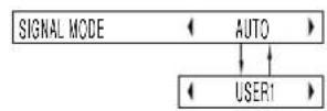
If "AUTO" is chosen, a setting closest to the user setting is automatically selected. (In the example above, only "USER1" is registered for user address.)
Note
- If you choose a user address registered for a signal that does not match the input signal, it is regarded as "no signal", and the projector will display the specified background colour.
STANDARD
Pressing the "ENTER" button resets all the adjustment parameter values to the factory default values, with a "STANDARD" indicator shown on the upper right corner of the menu.
- Obtain MENU window and move highlight cursor up and down through the menu with the ▲ or ▼ button.
-
Adjust parameter value for the selected item with the ◀ or button. For items that call for a separate bar graph, first show the bar graph with the "ENTER" or ◀ / button, then adjust parameter value with the ◀ or button.
-
RGB/YP B P R /DVI signals
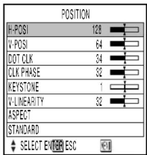
- Composite/S-video signal

■ HORIZONTAL POSITION (H.POSI)
▶ button: Shifts the picture to the right.
◀ button: Shifts the picture to the left.
▶ button: Shifts the picture upward.
◀ button: Shifts the picture downward.
■ VIDEO SIZE
(Vaild for composite video/S-video only)
▶ button: Increases picture size.
◀ button: Reduces picture size.
DOT CLK
(Vaild for RGB signals only)
Fine, regular patterns on the screen may be disturbed by fine stripe noise called moire. Dot clock adjustment allows the user to minimize this moire.
■ CLK PHASE (for RGB signals only)
Adjust clock phase after you are finished with dot clock adjustment.
Clock phase adjustment allows the user to minimize visible noise with the ◀ or button.
Note
- A noise may not disappear when adjusting the dot clock or clock phase at UXGA signal mode.
- Clock phase is adjustable for each of R, G, and B signals. Final parameter values are saved to memory.
- Clock phase adjustment is not available for digital RGB signals.
KEYSTONE
Keystone distortion can be corrected only along either horizontal bound of the picture:

Note
- Keystone distortion can be corrected to ± 20^ of the angle of tilt for the projector. However, the greater the correction amount, the more the picture quality will deteriorate, and the harder it will become to achieve a good level of focus. To obtain the best picture quality, set up the projector and screen in such a way that the amount of keystone correction required is as minimal as possible.
- The picture size will also change when correction of keystone distortion is carried out.
V. LINEARITY
After you are finished with keystone adjustment, adjust vertical linearity with the ◀ or button.
Vertical linearity is not adjustable if no correction was made to keystone distortion.
Adjusting the Zoom/Focus
ASPECT
Aspect ratio is adjustable only for composite video, S-video, or YPBPR signals complying with the NTSC (480i or 480p) or PAL (625i) standards.

flowchart
graph TD
    A["ASPECT"] --> B["AUTO"]
    B --> C["16:9"]
    C --> D["4:3"]
    D --> E["S4:3"]
[AUTO]: (S-video only)
If an S1 video signal is applied to the S-VIDEO port, the picture is automatically switched to the 16:9 aspect ratio.
[16:9]: The image is vertically compressed into a 16:9 ratio.
[4:3]: The aspect ratio inherent to the input video signal is left intact when projected onto the screen.
[S4:3]: Picture size is compressed to 75% of the original picture size when projected. (This mode is useful when viewing pictures with the standard 4:3 aspect ratio on a wide screen with the 16:9 aspect ratio.)
What Is S1 Video?
- The S1 video is the wide-aspect-ready S-video format containing an aspect sense signal for squeezed videos fed from video equipment.
- If "AUTO" is chosen, the projector automatically compresses the squeezed input video into the 16:9 aspect ratio if it detects the aspect sense signal.
Caution
- If you choose an aspect ratio that does not match the source video's aspect ratio, you will see a picture with an aspect ratio not the same as that of the original picture. Choose the appropriate aspect ratio carefully to match that of the original picture.
Note
- If the picture size is compressed or enlarged by using the 16:9 aspect ratio when the projector is used for profitable purpose or in the presence of an audience (for example, in a coffee shop or at a hotel etc.), it may infringe the rights of the copyright owner of the original picture.
- If a picture with the standard (4:3) aspect ratio is projected at a wide aspect ratio, parts of the picture may run over the screen bounds or the overall picture may be distorted. To view the picture at its original aspect ratio, choose the standard 4:3 aspect ratio.
■ STANDARD
Pressing the "ENTER" button resets parameter values for all the menu items to the factory default, with a "STANDARD" indicator shown in the upper right corner of the menu.
■ ZOOM
"ZOOM" is used to adjust projected picture size.
▶ button: Increases picture size.
◀ button: Reduces picture size.
When the picture size reaches the upper or lower limits, the colour of the arrows on the four corners will change from light blue to red.

■ FOCUS
"FOCUS" is used to adjust picture focus with the ▲ or ▼ buttons.
Changing the display language
- Highlight the desired language with the ▲ or ▼buttons (on the projector or remote control).
- Press the "ENTER" button to enter your selection.
Menus, setting items, adjustment screens, and control button names will be displayed in the language the user chooses.
The available languages are:
English, Deutsch, Français, Español, Italiano, 中文 and 日本語.
Currently chosen language is displayed here.

Note
- The projector's on-screen display is set to the English language by default.
- Obtain the MENU window and select (highlight) the desired adjustment item with the ▲ or buttons (on the projector or remote control).
- Adjust the parameter value for the selected item with the ◀ or buttons.
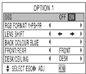
■ OSD (On-Screen Display)
ON: The name of the signal applied is displayed in the upper left corner of the screen whenever the input signal source is switched from one to another.
OFF: The signal name is not displayed even when an input source switching occurs.
RGB FORMAT
"RGB FORMAT" is used to select the video signal format depending on the signal applied to the RGB1 or RGB2 port: Only HDTV (1080i)

■ LENS SHIFT
"LENS SHIFT" is convenient for adjusting vertical picture position in situations where the projector is not easily accessible.

▶ button: Shifts the picture upward.
◀ button: Shifts the picture downward.
Note
- The screen picture move reverse direction when press the ◀ or button under the ceiling set up condition.
■ BACK COLOUR
"BACK COLOUR" is used to choose the background colour from blue or black when no signal is applied to the video input ports:

BLUE: Sets background colour to blue.
BLACK: Sets background colour to black.
Note
- If a signal with unknown or unidentifiable format is applied, it will be regarded as no signal and the screen be set to the selected background colour.
■ PROJECTION SCHEME 1
PROJECTION SCHEME 1 is used to choose the appropriate projection scheme from Front and Rear:
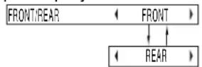
FRONT: Choose this option if pictures are projected from the front of a reflective screen.
REAR: Choose this if pictures are projected from the back of a translucent screen.
■ PROJECTION SCHEME 2
PROJECTION SCHEME 2 is used to choose the appropriate projection scheme from Floor and Ceiling:

FLOOR: Choose this option if the projector is installed on a floor-standing base.
CEILING: Choose if the projector is installed on the ceiling using the optional ceiling mount bracket.
- Obtain the MENU window and select (highlight) the desired adjustment item with the ▲ or buttons (on the projector or remote control).
- Adjust the parameter value for the selected item with the ◀ or buttons.
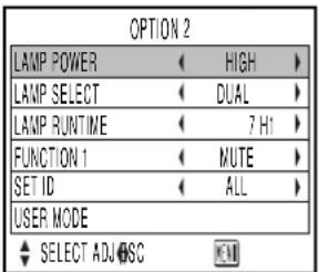
LAMP POWER
"LAMP POWER" is used to change the luminance of the projection lamp depending on user's needs or the viewing conditions. LAMP POWER < HIGH >
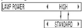
HIGH: Choose if a higher picture brightness is required. STANDARD: Choose for normal picture brightness.
Note
- If it is not necessary for picture brightness to be very high (in a small meeting room, etc.), it is advisable that you set BRIGHTNESS to "STANDARD". This will save power consumption and extend lamp life.
■ LAMP SELECT
"LAMP SELECT" is used to choose from Single Lamp and Dual Lamp modes depending on user's needs or viewing conditions. In Single Lamp mode, the projector may automatically select either lamp from the 2 lamps, or the particular lamp can be specified.

flowchart
graph TD
    A["LAMP SELECT"] --> B["DUAL"]
    B --> C["SINGLE"]
    C --> D["SINGLE 1"]
    D --> E["SINGLE 2"]
* Press and hold the "ENTER" button for approximately 3 seconds. (lamp with longer operating hours is turned off)
DUAL: Two lamps are used simultaneously. SINGLE: One of either lamps is used (lamp with shorter operating hours is automatically selected).
SINGLE 1: Lamp Unit 1 is always used.
SINGLE 2: Lamp Unit 2 is always used.
Caution
- Lamp can be selected without turning off the projector.
- If lamp mode is switched from "SINGLE", "SINGLE 1", or "SINGLE 2" into "DUAL", be sure to temporarily turn the projector OFF, then turn it ON again. The "DUAL" mode will become valid only after the projector is turned back ON.
Note
- When the currently active lamp exceeds 2000 hours of cumulative operating time, if in "SINGLE 1" or "SINGLE 2" mode, the other lamp takes over, provided that the cumulative operating time of that lamp does not exceed 2000 hours. If the cumulative operating time of the other lamp also exceeds 2000 hours when in "DUAL", "SINGLE", "SINGLE 1", or "SINGLE 2" mode, the projector will enter Standby mode after 10 minutes.
- If only one lamp is installed in the projector, set lamp mode to either "SINGLE 1" or "SINGLE 2". "SINGLE 1" or "SINGLE 2" is selected. If the corresponding lamp is not installed, the other lamp will turn on. The same holds for "SINGLE 2" mode. If "SINGLE" mode is selected, it may take approx. 90 seconds before the lamp turns ON.
LAMP RUNTIME
"LAMP RUNTIME" is used to cheque the cumulative operating hours of the two projection lamps.

"1": Lamp 1 operating hours is displayed.
"2": Lamp 2 operating hours is displayed.
Note
- If the cumulative operating hours exceeds 1800 hours, the hour indicator flashes in red.
■ SETTING FUNCTION 1 [FUNC 1]
FUNCTION 1 is used to specify the function of the remote control / "FUNC1" button. ("FUNC1" button functions differ between the PT-L6510E and PT-L6600E.)
- PT-L6510E
![PANASONIC PT-L6510E - ■ SETTING FUNCTION 1 [FUNC 1] - 1](/content/2026/06/1203271/images/2c5dd7b74b177471a0b9d9c15d04af2903538e62919fd38b87c34973ced5e83d.jpg)
flowchart
graph TD
    A["FUNCTION 1"] --> B["INDEX"]
    B --> C["MUTE"]
    C --> D["STANDARD"]
- PT-L6600E
![PANASONIC PT-L6510E - ■ SETTING FUNCTION 1 [FUNC 1] - 2](/content/2026/06/1203271/images/29da73dffb65b72b147bf7c8fb1a176bb52a648ba33e4f32a62ced1697edef22.jpg)
INDEX: Pressing the "FUNC1" button displays both still and motion images on a split screen (same as the "INDEX WINDOW" option in the MAIN MENU).
MUTE: Pressing the "FUNC1" button mutes the sound output.
STANDARD: Pressing the "FUNC1" button resets all the parameter values now in the menu to the factory default, with a "STANDARD" indicator shown in the upper right corner of the menu.
■ SETTING UNIT ID
UNIT ID is used to set projector IDs when the user wishes to control two or more projectors either simultaneously or separately.
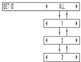
flowchart
graph TD
    A["SET ID"] --> B["ALL"]
    B --> C["1"]
    C --> D["2"]
    D --> E["3"]
"ALL": The projectors can be simultaneously controlled from any remote control regardless of their ID settings.
"1": The projector can be controlled from the remote control with its projector ID set to "1".
"2": The projector can be controlled from the remote control with its projector ID set to "2".
"3": The projector can be controlled from the remote control with its projector ID set to "3".
Note
- Unit ID is set to "ALL" by default. Hence ID number need not be set when only one projector is used.
- If the projectors are given ID numbers, their remote controls must be assigned the same ID numbers, respectively.
- If the unit IDs of two or more projectors are set to "ALL", the user will not be able to control them separately.
- The projector can be turned ON/OFF from the remote control only if the projector ID is set in the remote control. For the details of projector ID setting, see page 15.
■ Registering/Deleting/Displaying User Mode
(For RGB/YP _B PR signals only)
Once adjustment settings are registered with User Mode, they are automatically loaded each time the projector is powered up. It is not necessary to readjust settings at every power on.
Registering User Mode
(e.g. Registering positioning data with "USER1")
- Apply an input signal you want to register, and then adjust the picture position, size, and others.
- Choose "USER MODE" on "OPTION2" and press the "ENTER" button.

- Choose "USER1" using the ◀ or buttons and press the "ENTER" button.
Note
- The user address has "USER1" to "USER3".
- After recognizing the flashing of the USER1 address display, press the "ENTER" button again.
- The above adjusted settings has been registered with "USER1". Similarly you can also register settings with "USER2" or "USER3".
Deleting User Mode
(e.g. Deleting the data of "USER1")
- Choose "USER MODE" on "OPTION2" and press the "ENTER" button.
- Choose "DELETE" using the ▲ or buttons.
- Choose the address (USER1) you want to delete data from using the ◀ or buttons and press the "ENTER" button.
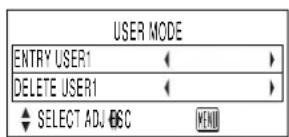
- After recognizing the flashing of the address display, press the "ENTER" button again to delete the data of the address.
Displaying User Mode
The User Mode can be displayed by following the steps described in "SIGNAL MODE" on page 31.
The projector is equipped with an RS-232C standard serial terminal at the rear. It is therefore possible to connect it to a computer for control.
■ Connection
- Single • Plural
Side interface panel


flowchart
graph LR
    PC["PC"] -->|D-sub 9-pin (male)| Unit1["Unit 1 interface panel"]
    Unit1 -->|D-sub 9-pin (female)| Unit2["Unit 2 interface panel"]
    Unit1 -->|D-sub 9-pin (male)| Unit2
    Unit1 -->|D-sub 9-pin (female)| Unit2
    Unit1 -->|D-sub 9-pin (male)| Unit2
    Unit2 -->|D-sub 9-pin (male)| Unit2
    Unit2 -->|D-sub 9-pin (female)| Unit2
    Unit2 -->|D-sub 9-pin (male)| Unit2
    Unit2 -->|D-sub 9-pin (female)| Unit2
    Unit2 -->|D-sub 9-pin (male)| Unit2
    Unit2 -->|D-sub 9-pin (female)| Unit2
    Unit2 -->|D-sub 9-pin (male)| Unit2
    Unit2 -->|D-sub 9-pin (female)| Unit2

    style PC fill:#f9f,stroke:#333
    style Unit1 fill:#ccf,stroke:#333
    style Unit2 fill:#ccf,stroke:#333
■ Pin assignments and signal names
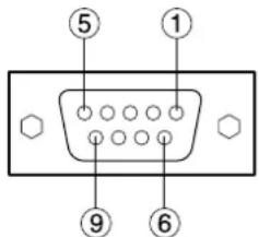
D-Sub 9-pin (female) external appearance
| Pin No. | Signal name | Description |
| 1 | NC | |
| 2 | TXD | Send data |
| 3 | RXD | Receive data |
| 4 | Connected internally | |
| 5 | GND | Ground |
| 6 | NC | |
| 7 | CTS | Connected internally |
| 8 | RTS | |
| 9 | NC |
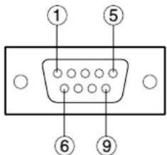
D-Sub 9-pin (male) external appearance
| Pin No. | Signal name | Description |
| 1 | NC | |
| 2 | RXD | Receive data |
| 3 | TXD | Send data |
| 4 | NC | |
| 5 | GND | Ground |
| 6 | NC | |
| 7 | RTS | Connected internally |
| 8 | CTS | |
| 9 | NC |
■ Communication requirements
| Signal level | RS-232C |
| Sync method | Start-stop transmission |
| Baud rate | 9 600 bps |
| Parity | None |
| Character length | 8 bit |
| Stop bit | 1 bit |
| X parameter | None |
| S parameter | None |
Basic format
Transmission from the computer begins with STX, then the command, parameter and ETX are sent in this order. Colon (:) is not required when transmitting the command which does not need a parameter.

flowchart
graph TD
    A["STX C1"] --> B["00 to 99"]
    B --> C["ID designate"]
    C --> D["ID characters (2 Bytes)"]
    D --> E["Colon"]
    E --> F["Command 3 characters (3 Bytes)"]
    F --> G["Colon"]
    G --> H["Parameter (1 to 5 Bytes)"]
    H --> I["End"]
Caution
- On commencement of lamp lighting, commands cannot be sent or responses received for approximately 10 seconds. Be sure to send any commands and receive responses 10 seconds. (Applies to the PT-L6600E / PT-L6600EL only)
- When transmitting several commands, wait for a response from the projector before sending the next command. When sending commands without parameters, a colon is not necessary.
- When it is unnecessary to designate an ID code, send the format without the part to ID designate it.
Note
- If a wrong command is received, the projector sends ER401 back to the computer.
- When using control from the remote terminal, commands cannot be received at the serial terminal.
- Projector ID supported on the RS-232C interface is 0 (ALL) to 99.
- The remote control ID is set from 0 to 3. If a command is sent with a projector ID specified, the projector will return answer back only if the ID contained in the command matches the projector ID or the projector ID is set to ALL.
■ Control command
When controlling the projector using a computer, commands are as follows:
| Command | Control contents | Remarks |
| PON | Power ON | During standby mode, commands other than PON are invalid.· While the lamp is ON and being controlled, the PON command is invalid.· After turning the lamp OFF, if the PON command is sent during cooling fan operation, lighting control will function for approximately 95 seconds (PT-L6510E) or 40 seconds (PT-L6600E) after turning OFF to protect the lamp. |
| POF | Power OFF | |
| AVL | Volume | Parameter000 = Adjustment value 0:063 = Adjustment value 63 |
| AMT | Mute (audio mute) | Parameter0 = Mute (audio mute) off 1 = Mute (audio mute) on |
| IIS | Switch input modes | ParameterVID = VIDEO SVD = S-VIDEORG1 = RGB1 RG2 = RGB2 DVI = DVI |
| ORF | Switch RGB 1 · 2 input signals | Parameter0 = RGB 1 = YPBPR (Only 1080i input) |
| Q$S | Check lamp lighting condition | Parameter0 = Standby 1 = Lamp lighting control2 = Lamp lit 3 = Lamp off control |
| QLS | Check lamp lighting condition | Parameter0 = Lamp 1 and 2 off 1 = Lamp 1 on2 = Lamp 2 on 3 = Lamp 1 and 2 on |
| OSI | SET ID | Parameter0 (ALL) to 99 |
| OFZ | Freeze | Parameter0 = Freeze off 1 = Freeze on |
| OMN | Menu | |
| OEN | Enter | |
| OCU | Cursor up | |
| OCD | Cursor down | |
| OCL | Cursor left | |
| OCR | Cursor right | |
| OAS | Auto setup | |
| OSH | Shutter | |
| DZU | D.Zoom up | |
| DZD | D.Zoom down | |
| FC1 | Function 1 |
■ Cable specifications
< Connecting to a computer >
Caution
- Purchase an appropriate communication cable to connect a computer to the serial terminal.
| Projector | NC | NC | Computer(DTE specifications) |
| 1 | 1 | ||
| 2 | 2 | ||
| 3 | 3 | ||
| 4 | NC | NC | 4 |
| 5 | 5 | ||
| 6 | NC | NC | 6 |
| 7 | 7 | ||
| 8 | 8 | ||
| 9 | NC | NC | 9 |
■ USB control
The same control as RS-232C can be performed using USB. Need to prepare device driver and control software.
Using the remote terminal
Using the remote terminal built into this projector, it is possible to operate the projector from an external location from where infrared remote control signals cannot be received, by using a remote control panel.
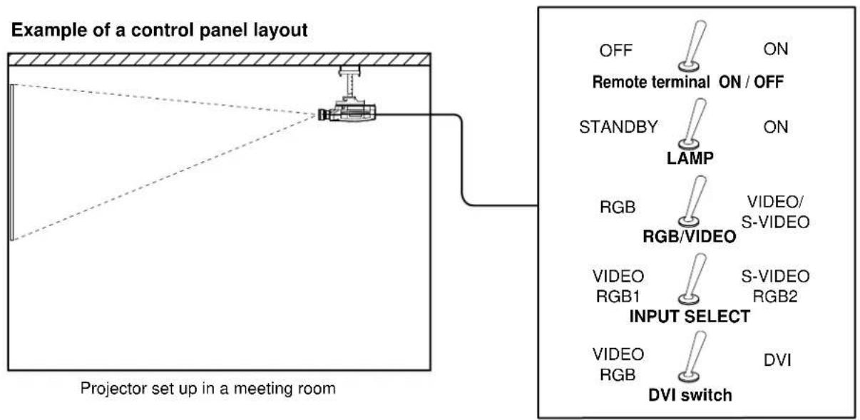
flowchart
graph TD
    A["Projector set up in a meeting room"] --> B["Projection Setup"]
    B --> C["Projector Setup"]
    C --> D["LAMP"]
    D --> E["ON / OFF"]
    D --> F["ON"]
    D --> G["ON"]
    D --> H["ON"]
    D --> I["ON"]
    D --> J["ON"]
    D --> K["ON"]
    D --> L["ON"]
    D --> M["ON"]
    D --> N["ON"]
    D --> O["ON"]
    D --> P["ON"]
    D --> Q["ON"]
    D --> R["ON"]
    D --> S["ON"]
    D --> T["ON"]
    D --> U["ON"]
    D --> V["ON"]
    D --> W["ON"]
    D --> X["ON"]
    D --> Y["ON"]
    D --> Z["ON"]
    D --> AA["ON"]
    D --> AB["ON"]
    D --> AC["ON"]
    D --> AD["ON"]
    D --> AE["ON"]
    D --> AF["ON"]
    D --> AG["ON"]
    D --> AH["ON"]
    D --> AI["ON"]
    D --> AJ["ON"]
    D --> AK["ON"]
    D --> AL["ON"]
    D --> AM["ON"]
    D --> AN["ON"]
    D --> AO["ON"]
    D --> AP["ON"]
    D --> AQ["ON"]
    D --> AR["ON"]
    D --> AS["ON"]
    D --> AT["ON"]
    D --> AU["ON"]
    D --> AV["ON"]
    D --> AW["ON"]
    D --> AX["ON"]
Control panel located in a different room
Pin assignment and control
Short pin 1 and pin 9 when controlling.
D-Sub 9-pin (female) external appearance
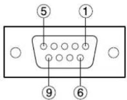
| Pin No. | Name | Description | |
| Short with pin Open | |||
| 9 | Remoto terminal ON / OFF | On | Off |
| 2 | Lamp | On | Off (standby) |
| 3 | RGB/VIDEO | VIDEO | RGB |
| 5 | Switch input modes | S-VIDEO (When 3is VIDEO) | VIDEO (When 3is VIDEO) |
| RGB2 (When 3is RGB) | RGB1 (When 3is RGB) | ||
| 6 | Switch DVI modes | DVI (When 3is RGB) | VIDEO (When 3is VIDEO)RGB (When 3is RGB) |
Note
- The "POWER", "RGB" and "VIDEO" buttons on the remote control and projector will not operate when pins 1 and 9 are shorted. RS-232C commands will also be ignored.
- Do not short pins. 1, 2, 3, 5 or 6 when pin 9 is open. If this is done, the projector will ignore signals from the remote control.
Indication of lamp monitor
This projector is equipped with 3 indicators to show when a lamp needs replacement or there is an abnormal internal temperature. These lamps flash or light up to indicate a problem.
Turn the power off and follow the steps below.
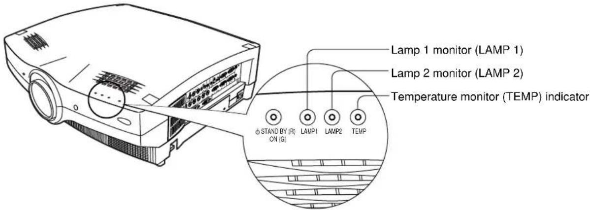
(Rear view of projector)
| Indicator Display | Condition | Check Measures | ||
Temperature monitor TEMP TEMP | Red lamp flasing(lamp unit lit)(PT-L6510E) | The inside is at an abnormally high temperature, or there are sudden temperature changes. | • Is something blocking the vent?• Has the projector been operating in a hot location?• Is the air filter clogged? | • Remove the object blocking the vent.• Use the projector only in an environment having a temperature of 0 °C to 40 °C and humidity of 20% to 80% (with no condensation).• Turn the power off by following the steps on page 23 and clean the air filter. (See page 41) |
| Red lamp lit(lamp unit lit) | The ambient temperature or internal temperature is high. | |||
| Red lamp flashing(lamp unit not lit) | The lamp unit automatically shuts off (switches to standby state) due to abnormally high ambient temperature or internal temperature. | |||
| Red lamp lit(Lamp unit not lit)(PT-L6600E) | The lamp unit has automatically turned off (standby mode) because of a high temperature or sudden rise in internal temperature. | |||
Lamp monitor  LAMP1 LAMP2 LAMP1 LAMP2 | Red lamp lit | It is time to replace the lamp unit. | Is replace lamp displayed on the screen when the power is turned on? | Lights when lamp runtime exceeds 1800 hours. Have your dealer replace the lamp unit. |
| Red lamp flashing | Detected the Lamp curcuit abnormal condition. | Are you turning the power back on immediately after it has been turned off? | Wait until the light source lamp cools off before turning the power back on. | |
| There is a malfunction in the lamp circuit | Turn the power off by following the steps on page 23 and consult your dealer. |
Caution
• To solve any problems that the TEMP and LAMP monitor show, first turn the power off by following the steps on page 23.
- If the main power turns off after the TEMP monitor flashes, the projector has malfunctioned. Please consult your dealer.
Cleaning and replacing the air filter
If too much dust accumulates in the air filter, the temperature inside main unit will become high.
- With the PT-L6510E, the temperature sensor (TEMP) lamp will flash.
- With the PT-L6600E, the temperature sensor (TEMP) lamp will flash and the light source lamp will go out.
Clean the air filter approximately every 100 hours of use, although more frequent cleaning may be necessary depending on the environment.
■ Cleaning method
1. Turn the Main Power off and remove the power plug.
Turn the power off by following the steps on page 23, and remove the power plug.
2. Remove the air filter cover.
Remove the air filter cover by pushing down on the tab and pulling forward.

natural_image
Line drawing of a projector with an inset showing its internal components (no text or symbols)3. Clean the air filter.
Remove accumulated dust using a vacuum cleaner.
Caution
- Be careful not to suck the air filter into the vacuum cleaner.
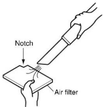
4. Attach the air filter and cover.
Place an air filter inside the air filter cover, and replace the cover by reversing the step described in (2).
Caution
- Place the air filter aligning the notch toward the upper right direction.
- Do not operate the projector without the air filter.
If the projector is operated without the air filter, dust will enter the unit and may cause a malfunction.
Note
- If dust cannot be removed with a vacuum cleaner, it is time to replace the filter. Please consult your dealer. Replace the air filter when replacing the lamp unit.
Replacing the lamp unit
Caution!
Replacement of the lamp unit should only be carried out by a qualified technician.
Caution!
Replace the lamp unit only after it has completely cooled off.
Notes when replacing the lamp unit:
- The internal pressure of the light source is high, therefore if it is struck by hard objects or dropped, it may cause damage. Be careful when handling.
- Handle the old lamp unit with care as it is easily broken.
- A Philips screwdriver is necessary when replacing the lamp unit. Be careful not to slip when using the screwdriver.
Caution
- The lamp unit is sold separately. Please consult the service/parts centre at your dealer.
| Model No. | Lamp unit model No. |
| PT-L6510E | ET-LAL6510 (1 lamp) • ET-LAL6510W (2 lamps) |
| PT-L6600E |
- Lamps other than those indicated above must not be used with this projector. Be sure to use the specified lamp.
■ Lamp replacement period
The light source lamp of this projector has a life cycle of 2000 hours (Lamp power---hi, Lamp selection---dual setting). However, this duration may be reduced depending on the usage of the projector-the frequency in which the light is turned on and of its intervals affect the life of the lamp. Therefore it is recommended that a spare lamp be made available before 2000 hours have elapsed. If the lamp unit is not replaced after 1800 hours, the power will automatically shut off after 2000 hours and enter standby mode. If the power is turned on after 2000 hours, it will turn off automatically after approximately 10 minutes and enter standby mode.
Note
- 2,000 hours is a guideline for replacement, not a guarantee time.
• Display after 1800 hours
The lamp monitor indicators (LAMP 1 or LAMP2) will light after the lamp unit runtime has elapsed 1800 hours even during standby mode.
An on-screen message indicating lamp replacement is necessary will be displayed on the screen 30 seconds.
(This on-screen message will disappear after 30 seconds or the projector operation buttons remote control buttons are operated.)
This on-screen message does not disappear, unless a "MENU" buttons or sound adjustment "(VOLUME +/-)" buttons will be pushed, if it reaches in 2000 hours.

■ Lamp unit replacement steps
Caution
- After 2000 hours of operating the same lamp, it is only possible to operate the unit for approximately 10 minutes. Replace the lamp and steps 8 to 14 must be completed within 10 minutes:
- Turn the power off by following the steps on page 23, remove the power plug and confirm that the surroundings of the lamp unit have cooled off.
- Using a Philips screwdriver, remove the 4 screws on the lamp unit cover located on the rear of the projector.
- Remove the lamp unit cover by pulling it forward.
Caution
- Be careful not to break the tab located in the centre of the lower side of the lamp unit cover.

- Use a Phillips screwdriver to loosen the two lamp unit fixing screws until the screws turn freely. Then hold the handle of the lamp unit and gently pull it out from the projector.
Caution
The lamp unit will be hot after it has been used.
You might get burned if you touch it while it is still hot.
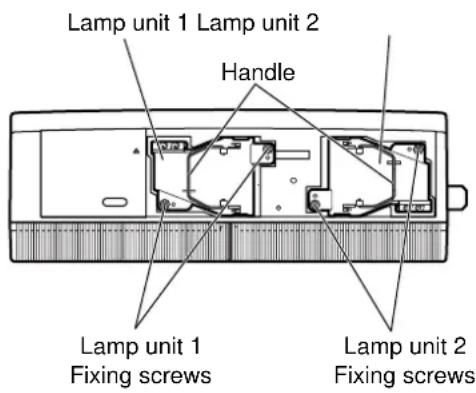
-
Install the new lamp unit.
-
Use a Phillips screwdriver to securely tighten the 2 lamp unit fixing screws.
-
Install the lamp unit cover, and then use a Phillips screwdriver to securely tighten the lamp unit cover fixing 4 screws.
Caution
- Firmly install the lamp unit and lamp unit cover. If not installed firmly, a protection circuit will function and the power will not be turned on.
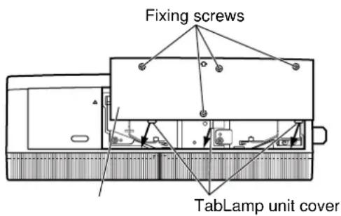
- Insert the power cord plug into the wall outlet and then press the MAIN POWER switch.
Caution
- If the power does not turn on even after turning the MAIN POWER switch "I", turn the MAIN POWER "O", confirm that the lamp unit and door are installed correctly, and turn on again.
-
Press the "POWER" button so that a picture is projected onto the screen.
-
Press the "MENU" button to display the MAIN MENU screen, and then press the ▲ and ▼buttons to move the cursor to select "OPTION2".
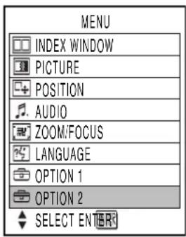
-
Press the "ENTER" button to display the "OPTION2" screen, and then use the ▲ and ▼buttons to select "LAMP RUNTIME".
-
Press and hold the "ENTER" button on the projector or the remote control for approximately 3 seconds.
The "LAMP RUNTIME" will change to "L1 RESET [POWER OFF]" or "L2 RESET [POWER OFF]".
Note
- If the "MENU" button is pressed, the lamp time resetting screen will be cancelled.


![OPTION 2 LAMP POWER ← HIGH ▶ LAMP SELECT ← DUAL ▶ L1 RESET [ POWER OFF ] FUNCTION 1 ← MUTE ▶ SET ID ← ALL ▶ USER MODE SELECT ADJ OSC](/content/2026/06/1203271/images/fc0f210b8df5ae06ebbb10008d7925e36cc85a0634cb8fde0ac3670a3e146bf5.jpg)
- Press the ▲ and ▼ buttons to select for replacement lamp setting.
L1 RESET: Replace the LAMP1
L2 RESET: Replace the LAMP2
L1+L2 RESET: Replace the LAMP1 & LAMP2
- Press the POWER button to turn off the power.
This will reset the cumulative usage time for the lamp unit to zero.
| Symptoms | Cheques |
| Power does not turn on | • Is the power cord plug correctly plugged in?• Is the MAIN POWER turned on?• Is electricity running to the power outlet?• Is the temperature monitor (TEMP) indicator on the front of the unit flashing or turned on? (See page 40)• Is the lamp monitor (LAMP) indicator on the front of the unit flashing or turned on? (See page 40)• Is the lamp unit door installed correctly?• A wrong ID is set. (See pages 15 and 36) |
| No image | • Is the lens cap still on the lens?• Is the image input correctly connected?• Is the input mode set correctly? (See page 23)• Is the black level adjustment set at the minimum level? (See page 30)• Is the equipment connected to the projector operating correctly?• Is the shutter function turned on? (See page 25) |
| Image is blurred | • Is the lens focused properly? (See page 23)• Is the projection distance correct? (See page 18)• Is the lens dirty?• Is the projector positioned directly in front of the screen? (See page 18) |
| Light colour/bad colour tone | • Is the colour density and colour tone setting correct? (See page 30)• Is the equipment connected to the projector correctly adjusted? |
| No sound | • Is the sound input correctly connected?• Is the volume set to the minimum level? (See page 23 and 27)• Is the shutter or mute turned on? (See page 25 and 35)• Is the cable connected to the AUDIO OUT terminal? |
| Remote control does not operate | • Are the batteries exhausted?• Are the battery polarities set correctly? (See page 14)• Are their any obstacles between the remote control and the remote control sensor? (See page 14)• Are you trying to operate the remote control beyond its operable range? (See page 14)• Are you controlling from external equipment using the REMOTE terminal? (See page 39)• Is their any external light interfering with remote control operation?• A wrong ID is set. (See pages 15 and 36) |
| Abnormal image | • Is the input mode properly set? (See page 23)• Is the correct signal system (TV system) selected? (See page 31)• Are their any malfunctions on the source side, such as bad video tapes?• Are you inputting a signal that is not compatible with this projector? (See page 48) |
| Does not display images from PCs | • Is the cable too long?• Is the video output signal setting of the notebook computer correctly set?Setting : Key (Read the operating instructions of the your PC.) |
| Model No. | PT-L6510E (XGA) | PT-L6600E (SXGA) | |
| Supply voltage | 220 V - 240 V AC, 50/60 Hz | ||
| Power consumption | 600 W (approx. 9 W in Standby mode with fan inactive) | ||
| LCD panelScanning | Panel size | 1.3 inch diagonal (aspect ratio: 4:3)with microlens array | |
| Display system | 3 transmissive LCD panels (3 primary colors) | ||
| Driving scheme | Active matrix | ||
| Pixel count | 786.432 pixels (1.024 x 768 dots) x 3 | 1.398.784 pixels (1.366 x 1.024 dots) x 3 | |
| Lens | Powered zoom | 1 to 1.3 | |
| powered focus control | F = 1.7 to 2.3, f = 49.1 to 63.8 | ||
| Projection lamp | 2 UHM lamps with 220 W rating each | ||
| Optical output | 4 200 Im (ANSI) 3 600 Im (ANI) | ||
| Composite/S-Video | H = 15.74/15.63 kHz, V = 50/60 Hz | ||
| RGB signal | H = 24 to 97 kHz, V = 50 to 120 Hz, PIAS (Panasonic Intelligent Auto Scanning) format | ||
| Dot clock frequency: under 132 MHz | Dot clock frequency: under 162 MHz | ||
| DVI-D signal | VGA60, S-VGA60, XGA60, S-XGA60 | ||
| YPBPRsignal | [480i] H = 15.75 kHz V = 60 Hz [625i] H = 15.63 kHz V = 50 Hz[480p] H = 31.5 kHz V = 60 Hz [720p] H = 45 kHz V = 60 Hz[1035i] H = 33.75 kHz V = 60 Hz [1080i] H = 33.75 kHz V = 60 Hz | ||
| YPBPRsignal | 480i, 480p, PAL (625i), 720p, 1 035i, 1080i | ||
| Compatible TV standards | 6 standards (NTSC, NTSC4.43, PAL, PAL-M, PAL-N, SECAM) | ||
| Screen size | 30 to 300 inches diagonal | ||
| Projection distance | 1.4 to 13.2 meters | ||
| Optical axis shift span | 10:10 to 1:19 | ||
| Aspect ratio | 4:3 (SXGA 5:4) | ||
| Projection scheme | Menu-selectable from front, rear, ceiling mount, and floor standing | ||
| Speaker | 2 oval speakers (4 x 7 cm) | ||
| Max. audio output power | 6 W (3 W + 3 W) (stereo) | ||
| DVI-D input/output | 1 set DVI-D 24pin | ||
| RGB1 (x1)input | 1 set BNC x 5[YPBPRinput] Y:1.0 V [p-p] including sync. signal P BPR: 0.7 V [p-p] 75 Ω[RGB input] 0.7 V [p-p] 75 ΩG-Sync.: 1.0 V [p-p] 75 ΩHD/SYNC: TTL-compatible, high-impedance w/ auto active Hi/Lo switchingVD: TTL-compatible, high-impedance w/ auto active Hi/Lo switching | ||
| Interface port Remote control | RGB2 input | High-density D-sub 15-pin connector (female)YP_{B}PRinput: Y = 1.0 V [p-p] including sync. signalP_{B}PR= 0.7 V [p-p] 75 ΩRGB input: 0.7 V [p-p] 75 ΩG-Sync.: 1.0 V [p-p] 75 ΩHD/SYNC: TTL-compatible, high-impedance w/ auto active Hi/Lo switchingVD: TTL-compatible, high-impedance w/ auto active Hi/Lo switching | |
| Audio input for RGB 1/2 | 1 set stereo minijack,0.5 V [rms] | ||
| VIDEO | BNC x 11.0 V [p-p] 75 Ω | ||
| S-video | 4-pin mini-Din x 1Y = 1.0 V [p-p] C = 0.286 V [p-p] 75 Ω | ||
| Audio input for composite/S-video | RCA jack x 2 (L/R),0.5 V [rms] | ||
| Audio output | 1 set stereo minijack, (monitor output, stereo-compatible),0 V [rms] to 2.0 V [rms] (variable) | ||
| RGB output | High-density D-sub 15-pin connector (female) x 1YP_{B}PRoutput: Y = 1.0 V [p-p] including sync. signalP_{B}PR$ = 0.7 V [p-p] 75 ΩRGB output: 0.7 V [p-p] 75 ΩG-Sync.: 1.0 V [p-p] 75 ΩHD: TTL-compatible, high impedanceVD: TTL-compatible, high impedance | ||
| SERIAL | 9-pin D-sub connector (female) Use the RS-232C serial portFor PC Control | ||
| REMOTE | 9-pin D-sub connector (female)For wired mode | ||
| WIRED input | M3 jack 1 setWired remote control, For daisy-chain control | ||
| USB input | 4-pin square connector Type BFor wired mouse | ||
| USB output | Type AFor daisy-chain control, Max. 5 V/0.5 A | ||
| Power cord | 2.5 metres | ||
| Enclosure | Resin mold part | ||
| Outer dimensions | Width: 495mm Height: 179 mm Depth: 495 mm | ||
| Weight | 13.8 kg | ||
| Operating conditions | Operating temperature range: 0 °C to 40 °COperating humidity range: 20 % to 80 % (with no condensation) | ||
| Power supply | 3 V DC (2 type-AAA dry batteries) | ||
| Control range | Approx. 7 m (in front of light receiver) | ||
| Weight | 108 g (with batteries) | ||
| Outer dimensions | (W): 33 mm (H): 40 mm (D): 168 mm | ||
The following table specifies the types of RGB signals compatible with the projector.
If signals other than this are applied, the projector may produce anything from a distorted display to simply the default (blue or black) background.
| Resolution | Compatible Signal | ||
| H x V Pixels | H. Scanning Frequency (kHz) | V. Scanning Frequency (Hz) | |
| VGA400 | 640 x 400 | 24.8 | 56.4 |
| 640 x 400 | 31.5 | 70.1 | |
| VGA480 | 640 x 480 | 31.5 | 59.9 |
| 640 x 480 | 35.0 | 66.7 | |
| 640 x 480 | 37.9 | 72.8 | |
| 640 x 480 | 37.5 | 75.0 | |
| 640 x 480 | 43.3 | 85.0 | |
| SVGA | 800 x 600 | 32.1 | 51.0 |
| 800 x 600 | 35.2 | 56.3 | |
| 800 x 600 | 37.9 | 60.3 | |
| 800 x 600 | 48.1 | 72.1 | |
| 800 x 600 | 46.9 | 75.0 | |
| 800 x 600 | 53.7 | 85.1 | |
| XGA | 1 024 x 768 | 48.4 | 60.0 |
| 1 024 x 768 | 56.5 | 70.1 | |
| 1 024 x 768 | 60.0 | 75.0 | |
| 1 024 x 768 | 65.5 | 81.6 | |
| 1 024 x 768 | 68.7 | 85.0 | |
| 1 024 x 768i | 35.5 | 86.8 | |
| 1 024 x 768 | 80.7 | 100.8 | |
| 1 024 x 768 | 94.0 | 120.0 | |
| MXGA | 1 152 x 864 | 63.9 | 70.0 |
| 1 152 x 864 | 67.5 | 75.0 | |
| 1 152 x 864 | 77.1 | 85.0 | |
| 1 120 x 750 | 50.1 | 60.1 | |
| 1 120 x 750i | 32.6 | 80.0 | |
| SXGA | 1 280 x 1 024 | 52.4 | 50.0 |
| 1 280 x 1 024 | 64.0 | 60.0 | |
| 1 280 x 1 024 | 72.4 | 66.3 | |
| 1 280 x 1 024 | 78.2 | 71.7 | |
| 1 280 x 1 024 | 80.0 | 75.0 | |
| 1 280 x 1 024* | 91.2 | 85.0 | |
| 1 280 x 1 024i | 46.2 | 86.0 | |
| 1 280 x 1 024i | 47.6 | 88.9 | |
| UXGA | 1 600 x 1 200 | 75.0 | 60.0 |
| 1 600 x 1 200 | 87.5 | 70.0 | |
| 1 600 x 1 200 | 93.8 | 75.0 | |
| MAC16 | 832 x 624 | 49.7 | 74.6 |
| MAC21 | 1 152 x 870 | 68.6 | 75.0 |
| HDTV | 1 920 x 1 035i | 33.8 | 60.0 |
| 720p | 1 280 x 720 | 45.0 | 60.0 |
| NTSC | 768 x 480i | 15.7 | 59.9 |
| PAL | 768 x 576i | 15.6 | 50.0 |
| 480p | 720 x 483 | 31.5 | 59.9 |
* PT-L6600E ONLY
Note
- The PT-L6600E has a pixel resolution of 1 366 x 1 024. Pixel data exceeding this resolution is converted into 1 366 x 1 024 pixels.
- The PT-L6510E has a pixel resolution of 1 024 x 768. Pixel data exceeding this resolution is converted into 1 024 x 768 pixels.
- Suffix "i" denotes interlaced scanning.
unit : mm

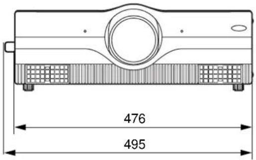

natural_image
Technical line drawing of an electronic device rear panel with ports and connectors (no text or symbols)Trademark acknowledgments
Trademark
• PS/2, VGA, and XGA are trademarks of U.S. IBM Corporation.
• Macintosh is a registered trademark of U.S. Apple Computers, Inc.
• PC-98 is a trademark of NEC Corporation.
• S-VGA is a trademark or registered trademark of the Video Electronics Standards Association.
- Windows is a registered trademark of Microsoft Corporation.
The rights of trademarks or registered trademarks not specified are recognised.

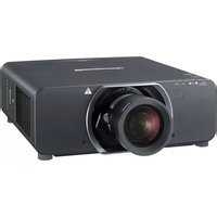
- LCD Projector Commercial Use
- Operating Instructions
- Dear Panasonic Customer:
- IMPORTANT SAFETY NOTICE
- WARNING:
- IMPORTANT: THE MOULDED PLUG (U.K. only)
- IMPORTANT SAFETY NOTICE 2
- Precautions with regard to safety .... 5
- Accessories 7
- Precautions on handling 8
- Example of System up....9
- Location and function of each part 10
- Using the Remote control unit.... 14
- Setting-up 18
- Starting to use 23
- Using the Freeze function 25
- Using the Shutter function 25
- Using the Digital Zoom function.... 26
- On-screen menus 27
- Using the INDEX WINDOW function 29
- Adjusting the picture 30
- Adjusting the position 32
- Adjusting the Zoom/Focus 33
- Changing the display language 33
- OPTION 1 settings.... 34
- OPTION 2 settings.... 35
- Using the SERIAL.... 37
- Using the remote terminal.... 39
- Indication of lamp monitor 40
- Cleaning and replacing the air filter 41
- Replacing the lamp unit.... 42
- Before asking for service 45
- Specifications.... 46
- Appendix.... 48
- Dimensions.... 49
- Trademark acknowledgments 49
- WARNING
- Caution
- Accessories
- Cautions regarding transportation
- Cautions regarding setting-up
- Notes on use
- About the screen
- Lamp
- About the liquid crystal panel
- About optical parts
- Before carrying out cleaning and maintenance, be sure to disconnect the power cord plug from the wall outlet.
- Example of System up
- System 1
- System 2
- System 3
- System 4
- Location and function of each part
- Projector < Top · Front and Side >
- Using the Remote control unit
- ■ Loading batteries
- Open battery compartment lid.
- Insert the batteries
- Close battery compartment lid.
- ■ Effective control range
- Note
- ■ Using laser pointer
- Laser Specifications:
- ■ Setting projector IDs for remote control
- ■ Using the remote control as a PC mouse
- Mode switch (Computer/Projector)
- - Page button
- - Arrow (▲) button
- - R-CLICK button
- - Click button
- ■ Using the remote control in wired mode
- ■ Projection Schemes
- ■ Installation Geometry
- ■ Setup precautions
- ■ Example of connecting with AV products
- ■ Example of connecting with PCs
- ■ Example of connecting with system switcher
- ■ Powering Up the Projector
- ■ Making Initial Adjustment / Setting input port
- ■ Powering Off the Projector
- ■ Leveling the Projector
- ■ Adjusting the Vertical Position of the Picture
- ■ Advice on the installation of exhaust guides
- Using the Freeze function
- Using the Shutter function
- Using the Digital Zoom (D.ZOOM +/-) function
- < For PT-L6510E >
- < For PT-L6600E >
- ■ Menu screens
- ■ Basic Menu Operations
- Press the "MENU" button.
- Select (highlight) the desired item with the ▲ or ▼ buttons.
- Press the "ENTER" button to enter your selection.
- Highlight the desired adjustment item with the ▲ or buttons, then change the parameter value with the ◀ or buttons.
- ■ Returning to the Previous Page
- ■ Menu Items Shown with White Characters
- ■ Menu Items Setting
- ■ Reset the Factory Default
- ■ PICTURE MODE
- COLOUR
- TINT
- ■ BRIGHT
- ■ CONTRAST
- ■ SHARPNESS
- TV-SYSTEM
- ■ W.BAL (White balance) R/G/B
- ■ SIGNAL MODE
- STANDARD
- ■ HORIZONTAL POSITION (H.POSI)
- ■ VIDEO SIZE
- DOT CLK
- ■ CLK PHASE (for RGB signals only)
- KEYSTONE
- LINEARITY
- Adjusting the Zoom/Focus
- ASPECT
- What Is S1 Video?
- ■ STANDARD
- ■ ZOOM
- ■ FOCUS
- Changing the display language
- ■ OSD (On-Screen Display)
- RGB FORMAT
- ■ LENS SHIFT
- ■ BACK COLOUR
- ■ PROJECTION SCHEME 1
- ■ PROJECTION SCHEME 2
- LAMP POWER
- ■ LAMP SELECT
- LAMP RUNTIME
- ■ SETTING FUNCTION 1 [FUNC 1]
- ■ SETTING UNIT ID
- ■ Registering/Deleting/Displaying User Mode
- Registering User Mode
- Deleting User Mode
- Displaying User Mode
- Basic format
- ■ Control command
- ■ Cable specifications
- ■ USB control
- Using the remote terminal
- Pin assignment and control
- Indication of lamp monitor
- Cleaning and replacing the air filter
- ■ Cleaning method
- Turn the Main Power off and remove the power plug.
- Remove the air filter cover.
- Clean the air filter.
- Attach the air filter and cover.
- Replacing the lamp unit
- Caution!
- Notes when replacing the lamp unit:
- ■ Lamp replacement period
- • Display after 1800 hours
- ■ Lamp unit replacement steps
- Trademark acknowledgments
- Trademark
Brand : PANASONIC
Model : PT-L6510E
Category : Video projector