TK-C685WPE - Surveillance Camera JVC - Free user manual and instructions
Find the device manual for free TK-C685WPE JVC in PDF.

User questions about TK-C685WPE JVC
0 question about this device. Answer the ones you know or ask your own.
Ask a new question about this device
Download the instructions for your Surveillance Camera in PDF format for free! Find your manual TK-C685WPE - JVC and take your electronic device back in hand. On this page are published all the documents necessary for the use of your device. TK-C685WPE by JVC.
USER MANUAL TK-C685WPE JVC
Thank you for purchasing this product.
Before beginning to operate this unit, please read the instruction manual carefully in order to make sure that the best possible performance is obtained.
Information for Users on Disposal of Old Equipment

[European Union]
This symbol indicates that the electrical and electronic equipment should not be disposed as general household waste at its end-of-life. Instead, the product should be handed over to the applicable collection point for the recycling of electrical and electronic equipment for proper treatment, recovery and recycling in accordance with your national legislation.
By disposing of this product correctly, you will help to conserve natural resources and will help prevent potential negative effects on the environment and human health which could otherwise be caused by inappropriate waste handling of this product. For more information about collection point and recycling of this product, please contact your local municipal office, your household waste disposal service or the shop where you purchased the product. Penalties may be applicable for incorrect disposal of this waste, in accordance with national legislation.
(Business users)
If you wish to dispose of this product, please visit our web page www.jvc-europe.com to obtain information about the take-back of the product.
[Other Countries outside the European Union]
If you wish to dispose of this product, please do so in accordance with applicable national legislation or other rules in your country for the treatment of old electrical and electronic equipment.
Dear Customer,
This apparatus is in conformance with the valid European directives and standards regarding electromagnetic compatibility and electrical safety.
European representative of Victor Company of Japan, Limited is:
JVC Technical Services Europe GmbH
Postfach 10 05 04
61145 Friedberg
Germany
Mounting to a firm place
As the unit rotates at high speed, mount it on a firm place with sufficient strength to support the vibration and weight of the unit.
Mass: Approx. 1.9 kg (TK-C685E/TK-C686E)
Approx. 5.5 kg (TK-C685WPE/TK-C686WPE)
If the ceiling material (e.g., decorated plywood, plaster board and bluster board) is not strong enough, apply reinforcement materials such as veneer plywood. (TK-C685E/TK-C686E)
If the strength is not sufficient, vibrations will cause fuzzy images on the monitor screen. In the worst scenario, the camera may even fall off and hit somebody, resulting in serious accidents.
Mounting the camera correctly with the designated mount brackets
Always use the designated mount brackets. Be sure to connect the fall prevention wire and tighten the fixing screws or nuts securely.
Using the correct power and voltage
The rated power of this product is AC24 V 50 Hz/60 Hz. Supplying a power beyond the rated value may result in failures and in the worst scenario, smoking and fire.
This unit is able to divert lightening conduction to itself and the connecting cables to a certain extent but this is not 100% guaranteed. For installation locations that are likely to suffer lightening strikes, be sure to take appropriate measures such as adding arrestor to the connecting cables.
Consult your dealer as special technique is required when installing this product.
Ensure that the fixing screws or nuts are tightened securely, otherwise, the unit may fall off.
Inspect the unit regularly.
Screws may be loosened due to vibration or deterioration of the mounting section. Perform regular inspections for loosened screws and check whether there is any danger of the unit falling off.
Handle the camera unit carefully when installing this product. Otherwise it may fall and result in injuries.
Features
Waterproof and weather-resistant chassis (TK-C685WPE/TK-C686WPE)
The anti-dust and drip-proof structure will shield the unit from rain, thus enabling it to be installed outdoors directly. (IP66 specifications)
※ TK-C685E/TK-C686E is intended for indoor use, and cannot be used outdoors or at places that are exposed to water.
Realizing a High Picture Quality
This product uses high resolution 410,000 pixels CCD and a new digital image processing IC to achieve a standard resolution of 540 lines and high resolution/high image quality of S/N50dB (standard).
High Power Zoom Lens
The optical 27 times (TK-C685E/TK-C685WPE) or optical 36 times (TK-C686E/TK-C686WPE) high power lens allows you to conduct detailed monitoring. The high power and large focal ratio F1.6 (WIDE edge) and bright zoom lens realize 1.0 lx (AGC MODE "SUPER", 50 %) high sensitivity during color mode.
ExDR (Wide Dynamic Range) function
It allows an object with luminance difference to be shot vividly.
Equipped with high precision high speed rotation platform
The newly developed direct drive rotation platform rotates at a high speed of 500^/s both horizontally and vertically, thus allowing the camera to move to the preset positions quickly. As it does not have a slowdown mechanism, it is very durable, has a high stopping accuracy and can rotate smoothly even at low speed.
Day/Night surveillance
This product is equipped with a day/night surveillance infrared filter mechanism. During low illuminance such as night time, switching out the infrared filter will switch the product to high sensitivity mode (B&W).
Private Mask function
This function allows you to blankout areas that you do not wish to display in the location to be recorded.
Tracking function (simple tracking)
This function tracks and shoots moving objects when home position is displayed.
Image Stabilizer
This function detects camera shaking and reduces image shaking. (TK-C686E/TK-C686WPE only)
Supports Pelco protocol
This product supports Pelco Inc.'s Pelco-D/P protocol.
Enables display of menu in multiple languages
You can select to display the menu of this product in English, French, German, Italian, or Spanish language. (Russian language not supported) (Page 38)
●Before starting an important recording, be sure to perform a test recording in order to confirm that a normal recording is possible.
- We do not accept liability for the loss of a recording in the case of it becoming impossible to record due to a problem in the video camera, VTR, hard disk recorder or video tape.
- The Home Motion Detect (Tracking) function is a simple function and cannot be used as a substitute for a security alarm. JVC shall not be liable for any inconveniences or damages caused in the event of error detection or when these functions cannot be detected. We shall not be liable for any inconveniences or damages caused as a result of operational failure for alarm input/output.
How to Read this Manual
■Symbols used in this manual
Note : States precautions to be taken during operation.
Memo : States restrictions on the functions or use of this equipment. For reference purposes.

:Indicates the page numbers or items to refer to.
■Contents of this manual
- JVC holds the copyright to this manual. Any part or all of this manual may not be reproduced without prior consent from the company.
- Product names of other companies described in this manual are trademarks or registered trademarks of the respective companies. Symbols such as ^TM , ^ and ^ are omitted in this manual.
- Design, specifications and other contents described in this manual are subject to change for improvements without prior notice.
- TK-C685E/TK-C686E is used in all illustrations on pages that are common among all camera models.
Contents
Getting Started
Features.... 3
Contents....4
Precautions....5
Name and Function of Parts 8
TK-C685E/TK-C686E 8
TK-C685WPE/TK-C686WPE 10
System Connection Example.... 12
Connection/Installation (TK-C685E/TK-C686E)
Camera Installation Procedures.... 14
Mounting the Camera 14
Switch Setting 19
Cable Connection 22
Connection/Installation (TK-C685WPE/TK-C686WPE)
Camera Installation Procedures.... 26
Mounting the Camera 26
Switch Setting 30
Cable Connection 32
Changing camera settings from remote control
Setting Procedures 34
Menu Display When Using Pelco Protocol 35
Flow of Menu Screens 36
LANGUAGE Setting.... 38
CAMERA FUNCTION1 screen 38
CAMERA FUNCTION2 screen 40
CAMERA TITLE/ALARM screen.... 42
CAMERA ALC screen.... 44
CAMERA VIDEO screen.... 46
AUTO PAN/PATROL/TRACE screen 47
POS.FUNCTION SET.. screen.... 50
FACTORY SETTINGS screen 53
Detailed setting
Private Mask Setting 54
Home Motion Detect (Alarm) Setting 56
HOME M.Detect (TRACKING) Setting.... 58
Manual Pan Limit Setting 60
Camera Title Setting 62
Area Display Mode Setting (Title) 63
Area Display Mode Setting (Direction).... 64
Remote Control Alarm Title Setting.... 65
Auto Pan setting.... 66
Auto Patrol Setting 68
Auto Trace Setting 70
Position Title Setting 72
Auto White Balance Setting 74
Others
Troubleshooting 76
Specifications....77
TK-C685E/TK-C686E 77
TK-C685WPE/TK-C686WPE 78
Precautions
Maintenance and operating environment
●TK-C685E/TK-C686E is an indoor camera. It cannot be used outdoors.
●TK-C685E/TK-C686E is a pendant mount camera. Be sure to install the product horizontally. The product will not work properly if it is tilted.
- TK-C685WPE/TK-C686WPE is for mounting to the wall. Be sure to install the camera unit horizontally. The product will not work properly if it is tilted.
●Do not store in the following environments.
It might result in malfunctions or failure.
●Hot or cold places beyond the allowable operating temperature range
Allowable operating temperature:
-10 °C to 50 °C (TK-C685E/TK-C686E)
-40 °C to 50 °C (TK-C685WPE/TK-C686WPE)
- Locations beyond the allowable operating humidity range of 20 %RH to 90 %RH. (condensation is not allowed)
- Near equipment that produces strong magnetic fields, such as transformers or motors.
●Near equipment that emits radio waves, such as transceivers and mobile phones. - Locations with excessive dust and sand.
- Locations that are subject to vibration such as inside the car or ship.
- Locations prone to moisture such as window side.
- Locations subject to steam or oil, such as kitchens.
●Special environment, such as those with combustible atmosphere - Locations that emit radiation, X-rays, salt attack or corrosive gases.
- Locations where medicine is used such as pool.
● Use of this product and cables connected to this product at locations where strong electric waves and magnetic waves are generated (e.g., near radio, TV, transformer, monitor, etc.) may cause noise interferences in the images or changes in the color.
●Inadequate heat ventilation may result in malfunction of this product.
Be sure not to block vents around the product.
This product discharges heat from the surface of the main unit.
- Do not install it at locations directly subjected to cold air such as near the vents of air-conditioners or at locations with high temperature. Condensation may occur inside the dome cover.
- When using TK-C685WPE/TK-C686WPE in a low temperature environment (-40°C to 50°C), video images may not appear for as long as two hours until the internal part is warmed up by the built-in heater. When using it in a low temperature environment, therefore, it is recommended that electric power be supplied at all times.
Transportation
●Do not throw away the original box of the unit. Keep it and use it for transporting the unit in future.
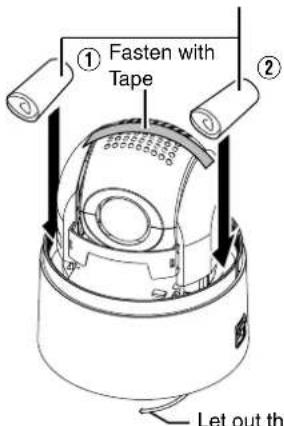
●As the camera unit is of an easily rotatable structure, secure the camera unit inside the dome cover such that it does not rotate before transporting. Otherwise, an error may occur during camera operation.
① Face the heat release vents upward and secure the lens section with tape.
②Insert cushioning material wrapped with air caps (approx. 50 mm x 200 mm) at two opposite sides of the camera.
- When mounting ceiling mount bracket to the camera unit during transportation, let out the tip of fall prevention wire so that it is not caught. If the fall prevention wire is caught in the gap of ceiling mount bracket, the ceiling mount bracket might not be able to detached from the camera unit.(TK-C685E/TK-C686E)
TK-C685E/TK-C686E
Cushioning material wrapped with air caps
text_image
① Fasten with Tape ② Let out thLet out the tip of fall prevention wire
■TK-C685WPE/TK-C686WPE
Cushioning material wrapped with air caps

text_image
① Fasten with Tape ②Precautions (continued)
Others
- Do not subject the lens to strong light source such as sun rays. This may cause the equipment to malfunction.
●This camera comes with a built-in AGC circuit. The sensitivity increases automatically at a dark place and the screen may appear grainy. This is not a malfunction.
●While AGC is activated, if a transceiver which causes strong electromagnetic wave is used near the camera, the picture may suffer from beat. Please use the camera more than three meters away from such transceivers. - When automatic iris is selected and AGC is ON, even if the iris setting is changed using the Iris Control button, the Increase Sensitivity function will be enabled and the brightness of the screen may not change. In this case, set AGC to OFF or set the iris to Manual.
- When automatic iris is selected, the Iris Control button may not work depending on the brightness of the screen (when the amount of light is not sufficient). In this case, set the iris to Manual.
- When this camera is used in the White Balance ATW-N, ATW-W (automatic adjustment) mode, the color tone may differ slightly from the actual color due to the principle of the automatic tracking white balance circuit. This is not a malfunction.
- If a high brightness object (such as a lamp) is shot, the image on the screen may have white vertical tailings. This phenomenon (smear) is characteristic of solid-state image sensors and is not a malfunction.
●The electronic shutter of this unit is set to 1/50 seconds by default. Use the remote control unit to change the electronic shutter to 1/120 seconds under fluorescent lighting in regions with commercial power of frequency 60 Hz. (Sensitivity level decreases slightly when this is set to 1/120 seconds.) - When the same position is monitored for 24 hours continuously over a long period, the increased contact resistance on the horizontal rotation section may cause noise interferences in the images and operation from the remote control unit may become unstable. Therefore, turn off and on the system power once a week to initialize the camera and clean the contact.
- Do not touch the dome cover with your hands. Dirty covers will cause image deterioration.
- Do not subject the dome cover to strong impact. It may result in damage and water seepage.
●The dome cover may fog due to the drastic change of temperature when humidity is high. - Do not connect an AC 24 V cable to AC 230 V power supply. The camera will be damaged. If the wrong cable is connected, the internal circuit will be damaged. Stop using the camera and send it to your nearest JVC dealer for repair. (Chargeable)
●To supply AC 24 V, use a AC 24 V supplying power unit that is insulated from AC 230 V line.
●As the dome cover is of a semiglobular shape, image distortion will occur at the hemispherical edge. When the hemispherical edge of this unit is masked and horizontal level is shot in a tilt direction, the hemispherical edge will enter the field angle. This may cause the upper edge of the screen to become black and the focus unclear. In this case, you can choose not to shoot the above area by using the tilt limit settings (Page 41).
- When shooting objects with a luminance difference or near a light source, ghost may occur on the screen. This is a feature of the dome cover and the built-in lens, and is not a malfunction.
●In particular, manual and auto pan operation near the TELE edge (telephoto side) may cause the screen to vibrate (unsmooth rotation). This is a feature of the motor and is not a malfunction.
●Long magnification zoom lens embedded into this product. Although the focus might be slightly unclear depending on the drastic change of temperature, it will not be a malfunction.
- When you preset focus, we ask you to adjust under actual usage temperature. If you feel unclear focus, please re-preset focus.
●Additionally, we recommend you to use either One Push AF or Manual focus adjustment when you feel unclear focus at your temperature environment.
Maintenance
●Turn off the power before performing maintenance.
●Wipe using a soft cloth. Wiping it with thinner or benzene may melt the surface or cause it to fog. For tough stains, wipe using a cloth that is dipped into a neutral detergent diluted with water, followed by wiping with a dry cloth.
Saving Energy
- When the camera is not in use for a long time, turn off the power of the system for safety and energy conservation reasons.
Disclaimer
●The Motion Detect feature is not designed to prevent thefts or fire disasters. Our company shall not be liable for any inconveniences or failures that occur.
●We shall not be responsible for any inconveniences or disturbances caused in the event of privacy invasion as a result of camera footages of this product.
Transporting the unit
- When transporting the unit, turn off the power of the system.
●Pack the unit with cushioning material so as to avoid shock when transporting.
●Handle the unit with care and do not subject it to vibration or shock.
■Consumable parts
The following are consumable parts. They must be replaced once they reach their lifetime.
The lifetime is only an estimation and differs according to the usage environment and conditions.
Replacement of consumable parts is chargeable within the guarantee period.
- Zoom lens assembly
Zoom operation ......2 million operations
Focus operation......4 million operations
●Slip ring ....Approx. 5 million operations
●Cooling fan ....Approx. 50,000 hours
●Alarm output 1 relay .....Approx. 100,000 times
■Auto Focus
This system including the camera allows the operation of the One Push Auto Focus and image AF functions from the remote control. However, depending on the object and the camera setting, it might be out of focus.
In this case, please adjust the focus manually.
- Objects which are difficult to be focused automatically
- When the brightness of the image plane is extremely high (bright)
- When the brightness of the image plane is extremely low (dim)
- When the brightness of the image plane is constantly changing (for example, a blinking light)
- When there is almost no contrasts
- When there are repetitive vertical striped patterns on the image plane
●Auto Focus is difficult to set under the following conditions
- When sensitivity is increased with AGC and the screen is grainy
- When there is less movement on the screen due to increased electronic sensitizing
- When there is no contour element in electronic zoom
■Zoom operation
The following phenomena are the result of the built-in lens performance and are not malfunctions.
- When manual operation or preset is selected, focus moves slightly after the zoom operation has stopped near the TELE edge.
●Manual zoom operation is not smooth. - When Preset is selected, the camera becomes out of focus for an instant during zooming.
●The camera may be out of focus during zooming.
■Preset Positions
You can configure up to a maximum of 256 preset positions on this product.
The number of configurable preset positions varies according to the switch settings.
Page 19 Switch Setting
Page 30 Switch Setting
Name and Function of Parts
TK-C685E/TK-C686E
■Ceiling mount bracket
Terminal
text_image
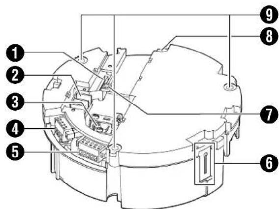
Technical diagram of a mechanical device with numbered components for identification①[ALARM I/O 2] Alarm Input 2 to 6/Alarm Output 2 Terminal (CN605)
This is a terminal for alarm input 2 to 6 and alarm output 2. This connects to the provided alarm cable. (Page 22)
| Pin number | Cable color Signal Name | |
| 1 BROWN Alarm input 2 | ||
| 2 RED | Alarm input 2 (COM) | |
| 3 ORANGE Alarm input 3 | ||
| 4 | YELLOW | Alarm input 3 (COM) |
| 5 | GREEN | Alarm input 4 |
| 6 | BLUE | Alarm input 4 (COM) |
| 7 | PURPLE | Alarm input 5 |
| 8 | GRAY | Alarm input 5 (COM) |
| 9 | WHITE | Alarm input 6 |
| 10 BLACK Alarm input 6 (COM) | ||
| 11 | PINK | Alarm output 2 |
| 12 | LIGHT GREEN | Alarm output 2 (COM) |
② [AC24V\~INPUT] AC24V power input terminal
This connects the camera to AC24V power. (Page 25)
③[VIDEO OUT] Coaxial cable connection terminal
This is an output terminal for composite video signals (1 V(p-p), output impedance 75 Ω). It connects switchers.
Setting switch
text_image
Technical diagram of a mechanical device with numbered components for identification④[CONTROL] Control signal connection terminal (J601)
This connects the camera to the remote control unit (RM-P2580). (Page 24)
| Pin number | Signal Name | Symbol |
| 1 | TX + | A |
| 2 | TX - | B |
| 3 | RX + | C |
| 4 | RX - | D |
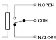
⑤[ALARM I/O 1] Alarm input 1/Alarm output 1 terminal (J602)
This is a terminal for alarm input 1 and alarm output 1. (Page 22)
| Pin number | Signal Name |
| 1 | Alarm output 1 (OUT1 NOP) |
| 2 | Alarm output 1 (COM) |
| 3 | Alarm output 1 (OUT1 NCL) |
| 4 | Alarm input 1 |
| 5 | GND |
⑥ Fall prevention wire fixing bracket
This attaches to the fall prevention wire 15 of the camera.
⑦ Wire clamp fixing hole
This is used to bundle wires. (Page 16)
⑧ Safety wire mounting hole
Mount wires from the ceiling slab or channel to this hole to prevent the camera from falling.
Camera

text_image
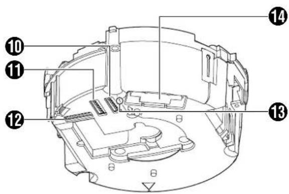
Technical diagram of a mechanical device with numbered components for identification⑨ Fixing holes (x3)
This hole is for mounting the ceiling mount bracket to the ceiling or the ceiling recessed bracket (WB-S685U: Sold separately).
⑩Setting Switch
This switch allows you to configure settings such as protocol and SYNC.
(Page 19)
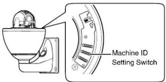
Machine ID Setting Switch
When the communication system is RS-485 multi DROP such as the RM-P2580 system, a machine ID will be set for every camera. (Page 20)
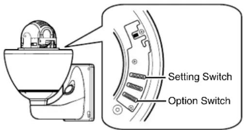
⑫Option Switch
Configure this switch when Pelco protocol is used. (Page 19)
13Power lamp
The lamp lights up in green when AC24V power is turned on.
⑭Camera connection terminal (female)
This connects to the connection terminal (male) of the camera.
15Fall Prevention Wire
This attaches to the fall prevention wire fixing bracket 6 of the camera.
16Front Mask
⑰Lens
Lens cannot be replaced.

natural_image
Technical line drawing of a cylindrical container with internal structure and labeled part (20), no text or symbols present.⑱Camera fixing lock knob (x2)
This knob secures the camera to the ceiling so that it does not fall.
19 Cable cover
Remove the cover to pull the cables from the side of the camera and mount the camera. (Page 16)
20Dome Cover
The dome cover is a delicate object. Handle it with care.
Note :
- Do not peel off the protective sheet which is attached at shipment, until the dome cover is mounted on the main unit. (Page 17)
Name and Function of Parts (continued)
TK-C685WPE/TK-C686WPE
Camera
text_image
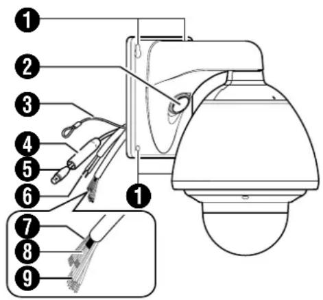
Diagram of a security camera with numbered parts for identification and assembly reference①Camera securing hole (x4)
This hole is used for mounting the camera on the wall.
② Cable connecting hole, cap
Remove the cap and pull out the cables from this hole for connection. (Page 27)
③Fall Prevention Wire
Connects the camera to the wall.
Secure the camera tightly to the anchor bolts used to mount the fall prevention wire on the wall. (Page 28)
4 Protection Cover
Upon connecting the coaxial cable, slide it to cover the connector ⑤ for coaxial cable connection. This cover insulates the metal portion of the connector from the structure inside the wall.
(Page 28)
⑤ Connector for Coaxial Cable Connection (BNC)
This is an output terminal for composite video signals (1 V(p-p), output impedance 75 K). It connects switchers.
⑥AC24V Power Cable
This connects the camera to AC24V power. (Page 28)
⑦ Alarm Input 1/Alarm Output 1 Cable (5 cables)
Alarm Input 1, Alarm Output 1 Cable.
(Page 32)
| Cable color Signal Name |
| GREEN/WHITE Alarm output 1 (OUT1NOP) |
| BLUE/WHITE Alarm output 1 (COM) |
| PURPLE/WHITE Alarm output 1 (OUT1NCL) |
| RED/BLACK Alarm input 1 |
| ORANGE/BLACK Alarm input 1 (COM) |
⑧Control Signal Connecting Cable (x4)
This connects the camera to the remote control unit (RM-P2580). (Page 32)
| Cable color Signal Name Symbol | ||
| BROWN/WHITE TX + | A | |
| RED/WHITE TX - | B | |
| ORANGE/WHITE | RX + | C |
| BLACK/WHITE | RX - | D |
■Camera (Interior)

text_image
Technical diagram of a security camera with numbered components and exploded view⑨Alarm Input 2 to 6/Alarm Output 2 cable
This is a cable for alarm input 2 to 6 and alarm output 2. (Page 32)
| Cable color Signal Name | |
| BROWN Alarm input 2 | |
| RED Alarm input 2 (COM) | |
| ORANGE Alarm input 3 | |
| YELLOW Alarm input 3 (COM) | |
| GREEN Alarm input 4 | |
| BLUE Alarm input 4 (COM) | |
| PURPLE Alarm input 5 | |
| GRAY Alarm input 5 (COM) | |
| WHITE | Alarm input 6 |
| BLACK | Alarm input 6 (COM) |
| PINK | Alarm output 2 |
| LIGHT GREEN | Alarm output 2 (COM) |
10Front Mask
⑪ Lens
Lens cannot be replaced.
⑫Dome Cover Fixing Screws (x4)
⑬Dome Cover
The dome cover is a delicate object. Handle it with care.
Note :
- It is covered with a protective sheet during shipment. Do not remove this sheet until installation is complete.
14 Option Switch
Configure this switch when Pelco protocol is used. (Page 19)
⑮Machine ID Setting Switch
When the communication system is RS-485 multi DROP such as the RM-P2580 system, a machine ID will be set for every camera. (Page 31)
⑯Setting Switch
This switch allows you to configure settings such as protocol and SYNC. (Page 30)
⑰Heater ON/OFF Switch
This is the ON/OFF switch for automatic control of the built-in heater.
This product comes with a built-in heater to prevent the dome cover from being covered with snow and frost as well as fogging. When installing the heater at an unrequired location, turn off the switch of the heater. Set the power of the heater to "ON" during use. (E) Page 27
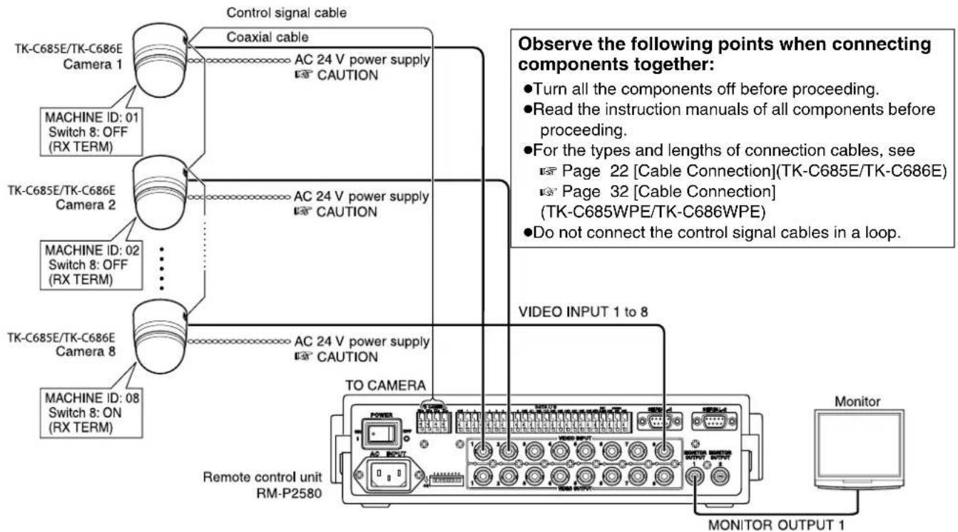
System Connection Example
CAUTIONS:
● The AC 24 V power supply must be isolated from the primary line. (ISOLATED POWER ONLY)
- In order to prevent an excessive current flow through the power supply wire or camera due to a short circuit, a fuse must be installed in the power supply line.
■ A system that employs the RM-P2580 as the controller
The following figure shows a system that can accommodate up to eight cameras. (100 positions can be preset per camera.)
flowchart
graph TD
    A["TK-C685E/TK-C686E Camera 1"] -->|Control signal cable| B["AC 24 V power supply"]
    A -->|Coaxial cable| B
    C["MACHINE ID: 01 Switch 8: OFF (RX TERM)"] --> B
    D["TK-C685E/TK-C686E Camera 2"] -->|AC 24 V power supply| B
    E["MACHINE ID: 02 Switch 8: OFF (RX TERM)"] --> B
    F["TK-C685E/TK-C686E Camera 8"] -->|AC 24 V power supply| B
    G["MACHINE ID: 08 Switch 8: ON (RX TERM)"] --> B
    H["TO CAMERA"] --> I["Remote control unit RM-P2580"]
    J["VIDEO INPUT 1 to 8"] --> K["Monitor OUTPUT 1"]
    L["Observe the following points when connecting components together:"]
    M["Turn all the components off before proceeding."]
    N["Read the instruction manuals of all components before proceeding."]
    O["For the types and lengths of connection cables, see Page 22 [Cable Connection"](TK-C685E/TK-C686E)]
    P["Page 32 [Cable Connection"] (TK-C685WPE/TK-C686WPE)]
    Q["Do not connect the control signal cables in a loop."]
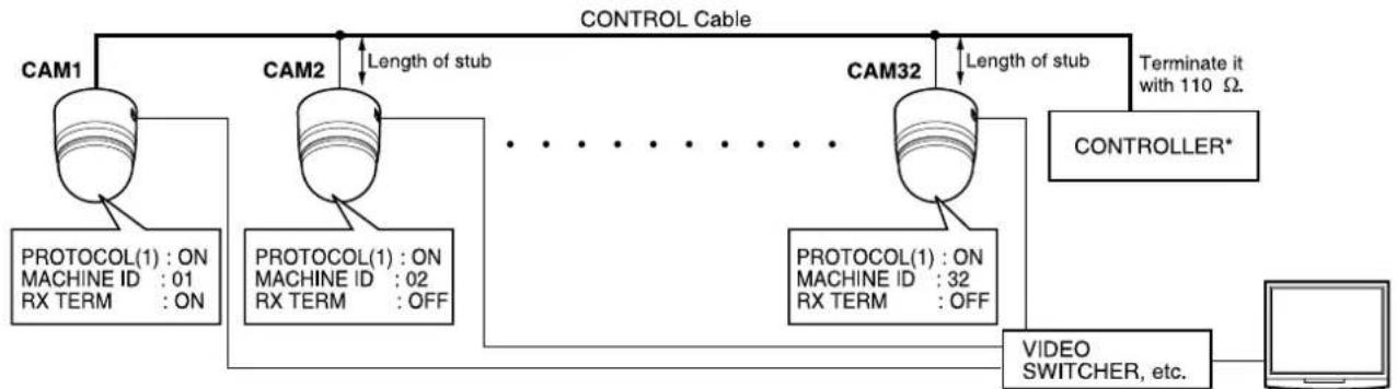
■ A system that does not employ the RM-P2580 as the controller
flowchart
graph TD
    A["CAM1"] -->|Length of stub| B["CAM2"]
    B --> C["CAM32"]
    C --> D["CONTROLLER*"]
    D --> E["Computer"]
    F["PROTOCOL(1) : ON\nMACHINE ID : 01\nRX TERM : ON"] --> A
    G["PROTOCOL(1) : ON\nMACHINE ID : 02\nRX TERM : OFF"] --> B
    H["PROTOCOL(1) : ON\nMACHINE ID : 32\nRX TERM : OFF"] --> C
    I["VIDEO SWITCHER, etc."] --> E
    J["CONTROL Cable"] --> A
    J --> B
    J --> C
    K["Terminate it with 110 Ω."] --> D
*TK-C685E/TK-C686E is used in the camera's illustration.
Note :
- Set the TERM switch of CAM1 to ON, and terminate at the controller with a resistance of 110 .
- Set the TERM switches of the other cameras to OFF.
- As long as there are no specifications, set PROTOCOL (2) to "OFF". (Page 19)
●An AC 24 V power source must be supplied to each camera.
CAUTIONS :
- The AC 24 V power supply must be isolated from the primary line. (ISOLATED POWER ONLY)
- In order to prevent an excessive current flow through the power supply wire or camera due to a short circuit, a fuse must be installed in the power supply line.
The following illustration shows a system in which a remote control unit (or a similar piece of equipment) controls a single camera.

flowchart
graph LR
    A["Switch 4 : OFF\n(Point to Point)\nSwitch 8 : ON\n(Terminated 110Ω)"] --> B["Video out"]
    B --> C["Control signal cable"]
    C --> D["AC 24 V\npower supply\n* CAUTION"]
    D --> E["Monitor"]
    E --> F["Controller"]
Observe the following points when connecting components together:
- Turn all the components off before proceeding
- Read the instruction manuals of all components before proceeding.
MEMO :
- If this camera or the cables connected to this camera are used in places subject to strong electromagnetic waves or other forms of magnetism, for example near a radio or TV transmitter, a power transformer or an electric motor, the picture may suffer from noise and colors may be affected.
An optionally available controller is required to use TK-C686E and TK-C686WPE camera. Please contact your local dealer or installer for more information about these controllers.
Use twisted-pair cables for the connections.
•Duplex
When the camera is controlled using the full duplex protocol, set Switch 5 to OFF.

flowchart
graph LR
    A["Camera"] --> B["RX+"]
    A --> C["RX-"]
    D["Controller"] --> E["TX+"]
    D --> F["TX-"]
    G["TX+"] --> H["RX+"]
    G --> I["RX-"]
Four wires must be connected.
For example (connection with an RM-P2580)
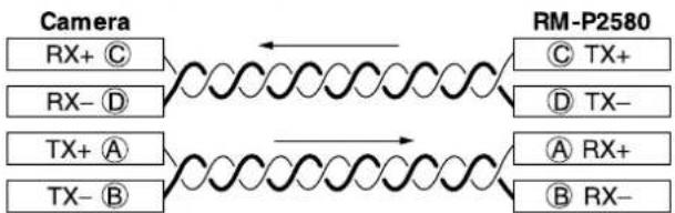
flowchart
graph LR
    A["Camera"] --> B["RX+ C"]
    A --> C["RX- D"]
    A --> D["TX+ A"]
    A --> E["TX- B"]
    F["RM-P2580"] --> G["C TX+"]
    F --> H["D TX-"]
    F --> I["A RX+"]
    F --> J["B RX-"]
*TK-C685E/TK-C686E is used in the camera's illustration.
- Simplex
When the camera is controlled using the simplex transmission protocol, set Switch 5 to ON.
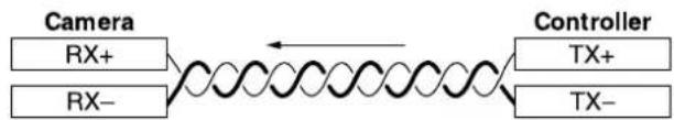
flowchart
graph LR
    A["Camera"] --> B["RX+"]
    A --> C["RX-"]
    D["Controller"] --> E["TX+"]
    D --> F["TX-"]
Two wires must be connected.
Camera Installation Procedures
Install the camera with the following procedures.
Preparation (Page 14)

Mounting the ceiling mount bracket (Page 17)

Mounting the camera (Page 17)
Mounting the Camera
Preparation
Be sure to put on protective glasses to protect your eyes from falling objects when mounting on the ceiling.
1 Make holes on the ceiling
- Use the provided template to make a hole (ø80 mm) for the connection cables to thread behind the ceiling.
- If necessary, also open a screw hole to mount the ceiling mount bracket to the ceiling. In this case, align the “ FRONT mark” of the template in the direction where the camera faces front and open the screw hole.
2Pull the cables from the hole in the ceiling
Pull out the fall prevention wire, power cable, coaxial cable, control signal cable, alarm signal cable and provided alarm cable that were mounted to the ceiling slab from the wall.
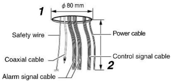
text_image
1 φ 80 mm Safety wire Power cable Coaxial cable Control signal cable Alarm signal cable3 Unfasten the ceiling mount bracket from the camera unit
The ceiling mount bracket comes attached to the camera unit. Before installing, unfasten the ceiling mount bracket from the camera unit.
① Check to ensure that the camera fixing lock knobs (x2) is not turned on.
- If it is locked, slide the camera fixing lock knobs to unlock in the direction as shown below.
② Push in the camera fixing lock knobs (x2) from both left and right sides in the direction as illustrated in the diagram.
●Unfasten the ceiling mount bracket on a table to prevent it from falling off.
Memo :
- If it is difficult to push in the camera fixing lock knob, push in while pressing the edge of camera (figure A) against the table where the process is being carried out.
③ Lift the camera unit upward to remove the ceiling mount bracket, and pull down in the direction as indicated.

text_image
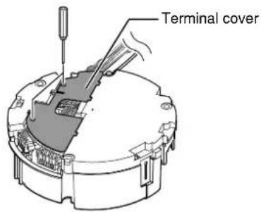
Camera fixing lock knob (x2) Ceiling mount bracket Camera unit4Remove the terminal cover
Loosen two screws on the ceiling mount bracket and remove the terminal cover.
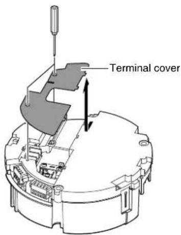
text_image
Terminal cover5 Set the switch (Page 19, 20)
Configure the setting switch and machine ID switch according to the system.

text_image
Machine ID switch Setting Switch Option Switch6Mount the safety wire that connects the ceiling mount bracket to the ceiling
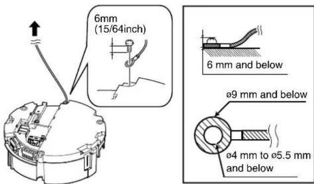
text_image
6mm (15/64inch) 6 mm and below Ø9 mm and below Ø4 mm to Ø5.5 mm and belowCAUTION
●Take note of the length, strength, pull and material (insulation) of the fall prevention wire and use one with a wire strength of more than 20 kg.
●The inner diameter of the ring section of the fall prevention wire mounted on the camera should be 4 mm to 5.5 mm and the outer diameter be 9 mm and below.
●The thickness of the screw head and the fall prevention wire (including the washer) should be 6 mm and below. If it is more than 6 mm, the screw will touch the ceiling and the camera cannot be installed horizontally.
- Use M4 fixing screws.
Memo :
●The wire should be insulated from the ceiling structure. If the ceiling structure is metal and insulation is not provided between the camera and the ceiling structure, image noise may occur.
7 Connect the cable (Page 22 to 25)
Connect cables to the terminal of the ceiling mount bracket. The connection cables consist of the alarm signal cable, coaxial cable, control signal cable and AC24V power cable.
① Provided alarm cable (Page 22)
This connects to devices with alarm input/output terminals.
② Coaxial cable (Page 23)
This connects to monitors.
③ Power cable (Page 25)
This connects to AC24V power.
④ Alarm signal cable (Page 22)
This connects to devices with alarm input/output terminals.
⑤ Control signal cable (Page 24) This connects to RM-P2580.

text_image
Safety wire ① Provided alarm cable ② Coaxial cable ③ Power cable ④ Alarm signal cable ⑤ Control signal cableNote :
- Do not connect an AC 24 V cable to AC 230 V power supply. The camera will be damaged. If the wrong cable is connected, the internal circuit will be damaged. Stop using the camera and send it to your nearest JVC dealer for repair. (Chargeable)
- For safety reasons, turn on the power only after all the connection is complete.
●To supply AC 24 V, use a AC 24 V supplying power unit that is insulated from AC 230 V line.
Mounting the Camera (continued)
8Handling cables
Thread the provided wire clamp through the wire clamp fixing hole of the ceiling mount bracket to tie all the wires.
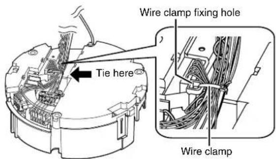
text_image
Wire clamp fixing hole Tie here Wire clampNote :
- To prevent the cables from tangling and coming off, be sure to thread a wire clamp through the wire clamp fixing hole to tie the cables.
- Tie the provided alarm cable with the wire clamp as shown in the diagram.
9Mount the terminal cover
Return the terminal cover that was removed in step 4 to its original position. The direction to pull out the cables changes according to the mounting method of the camera.
■Pulling out the cables from the side
text_image
Terminal cover■Pulling out the cables from the top

text_image
Safety wire (To go under the terminal cover) Terminal coverNote :
- Be sure to mount the terminal cover to prevent foreign objects or dust from entering.
- When pulling out the cables from the top, make the fall prevention wire go under the terminal cover and pull it out together with the other cables.
- When pulling out the cables from the side, remove the cable cover of the camera.
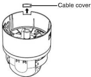
text_image
Cable coverMounting the ceiling mount bracket to the ceiling
1 Secure the ceiling mount bracket on the ceiling
Install such that the “↑FRONT mark” of the ceiling mount bracket faces the front.
Ensure that the connection cables are not caught in between and secure the ceiling mount bracket on the ceiling with 3 screws.
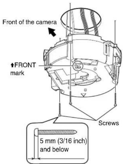
text_image
Front of the camera ↑FRONT mark Screws 5 mm (3/16 inch) and belowNote :
- Use M4 fixing screws and bolts.
- Use 4.1 wood screws.
●The length of the screws should be 25 mm and above. - Place the product horizontally and install. The camera will not operate properly if it is slanted.
●The screw head should be 5 mm and below. If the ceiling structure is metal, image noise may occur. - Do not use screws with screw heads that may sink below the surface when fastened. (e.g. countersunk screws) Doing so may damage the insulating resin parts and cause insulation to fail.
Memo :
●Always use 3 screws and mount securely.
●Tighten the screws again during maintenance just to be safe.
●The plastic parts on the ceiling fixing holes of the ceiling mount bracket act as an insulation between the ceiling mount bracket and the ceiling structure. If the ceiling structure is metal and insulation is not provided between the camera and the ceiling structure, image noise may occur. Be sure to provide insulation.
Mounting the camera to the ceiling
1 Remove the tape on the lens section
2Remove the lens cap
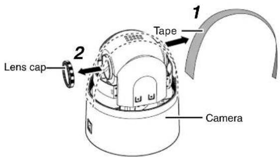
text_image
Lens cap 2 Tape 1 Camera3Mount the dome cover to the camera
① Check that the dome cover and lens are free from dirt.
② Turn the dome cover in a clockwise direction to mount.
Note :
- Be sure to turn the dome cover until it stops and tighten securely. Make sure that the dome cover is not slanted.
- Do not over-rotate the dome cover. This may damage the dome cover.
Memo :
- If it is difficult to screw on the dome cover, turn it in an anticlockwise direction until you hear a click sound, then turn it in a clockwise direction. It will screw on smoothly.
4Remove the dome cover protective sheet
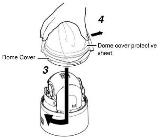
text_image
Dome Cover Dome cover protective sheet 4 3CAUTION
●The dome cover is an optical parts. Handle with care.
- When mounting the dome cover, make sure that there is no dirt inside the cover.
●Tighten the dome cover securely.
Mounting the Camera (continued)
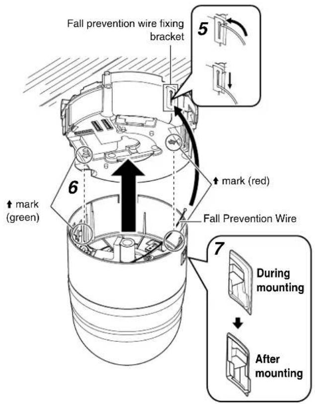
5Mount the fall prevention wire
Mount the fall prevention wire, which is attached to the camera, to the fall prevention wire fixing bracket of the ceiling mount bracket.
CAUTION
- Be sure to connect the fall prevention wire. Otherwise, the camera may fall.
●To prevent danger, do not leave the fall prevention wire dangling by the camera.
6Mount the camera
- Align the “↑” mark (green)/(red) inside the camera with the “↑” mark (green)/(red) on the ceiling mount bracket.
- Insert the camera into the ceiling mount bracket until you hear a click sound and mount it securely.
7 Check that the camera fixing lock knobs (x2) are sticking out.
If the camera is mounted on securely, the camera fixing lock knobs (x2) will stick out a little.
text_image
Fall prevention wire fixing bracket ↑ mark (green) ↑ mark (red) Fall Prevention Wire During mounting After mountingNote :
●Before mounting the camera, check that the camera fixing lock knobs are not locked (i.e., lock knobs are on top). The camera cannot be mounted if the lock knobs are locked.
- When pulling out the cables from the side, remove the cable cover of the camera. (Page 16)
8Lock
When the camera is mounted on the ceiling mount bracket, lower the camera fixing lock knobs (x2) in the direction of the arrow and secure the camera such that it does not fall off.

text_image
Camera fixing lock knob (x2)CAUTION
- Be sure to check that the camera fixing lock knobs (x2) are locked securely. Otherwise, the camera may fall.
●After mounting, check that the camera is mounted securely. Improper mounting may cause the camera to fall off.
Removing the Camera
① Slide the camera fixing lock knob toward the ceiling to unlock..
② Push in the camera fixing lock knobs (x2) from both left and right sides to remove the camera unit.
③ Remove the fall prevention wire according to the mounting procedures in the reverse order.
Switch Setting

text_image
Setting Switch Switch 1 : Multi Protocol Switch 2 : Preset Position Quantity Setting Switch 3 : Invalid (Set to ON) Switch 4 : PROTOCOL(1) Switch 5 : PROTOCOL(2) Switch 6 : SYNC Switch 7 : Invalid (Set to OFF) Switch 8 : RX TERM ON 1 2 3 4 5 6 7 8 9Option Switch
Setting Switch
Before mounting the camera, set the switches on the ceiling mount brackets.
The setting differs according to the system used.
●Multi Protocol (Switch 1)
| JVC Protocol OFF | |
| Pelco Protocol ON |
●Preset Position Quantity Setting (Switch 2) *1
| 100 positions | OFF |
| 256 positions | ON |
Memo :
- When Switch 1 is set to ON (Pelco protocol), the number of preset positions becomes 256 regardless of the settings of Switch 2.
- Switch 3
This switch must be set to OFF.
●PROTOCOL(1) (Switch 4) *1
Selects whether a single camera or multiple cameras are controlled in a system.
Set PROTOCOL(1) to multi DROP when connecting multiple cameras in series.
| Point to point OFF | |
| Multi DROP (when using the RM-P2580) ON |
(Initial set: OFF)
*When set to multi DROP, be sure to set the Machine ID of each camera. (Page 20)
●PROTOCOL(2) (Switch 5) *1
Set this switch according to the communication protocol used when controlling the cameras.
| Duplex (when using the RM-P2580) | |
| Simplex) |
(Initial set: OFF)
●SYNC (Switch 6)
When this switch is set to ON, the vertical sync of the camera becomes locked to the frequency of the AC power line.
| INT | OFF |
| LL | ON |
(Initial set: OFF)
*LL mode: 50 Hz area only.
- Switch 7
This switch must be set to OFF.
●RX TERM (Switch 8)
This switch sets whether or not the section between control signal terminals RX + and RX - is to be terminated (with a resistance of 110 Ω).
| Open | |
| Terminated (110 Ω) |
(Initial set: OFF)
*When the system in which this camera is used is a multidrop system (RS-485 system), set only the camera located at the extreme end of the control signal cables to "Terminated" and set the other cameras to "Open".
*1 : The settings of Switches 2, 4, and 5 are enabled only when Switch 1 is turned OFF (JVC protocol).
Option Switch
Configure this switch when Pelco protocol is used.
●Protocol Selection (Switches 1, 2, 3)
| Switch 1 | Switch 2 | Switch 3 | |
| Pelco Protocol | OFF | OFF | OFF |
●Parity Selection (Switches 4, 5)
| Switch 4 | Switch 5 | |
| NONE | OFF | OFF |
| NONE | ON | OFF |
| EVEN | OFF | ON |
| ODD | ON | ON |
●Baud Rate Selection (Switches 6, 7, 8)
| Switch 6 | Switch 7 | Switch 8 | |
| 1200 bit/s | OFF | OFF | OFF |
| 2400 bit/s | ON | OFF | OFF |
| 4800 bit/s | OFF | ON | OFF |
| 9600 bit/s | ON | ON | OFF |
Switch Setting (continued)
Machine ID Setting Switch
When controlling the system via a multi DROP system such as RM-P2580, a machine ID will be attached to the system to differentiate it from other connected cameras.
Match the machine ID with the [VIDEO INPUT] number of RM-P2580.
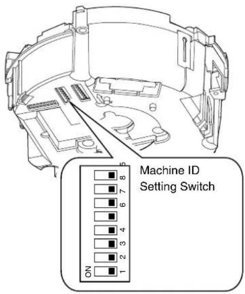
text_image
Machine ID Setting Switch ON 1 2 3 4 6 7 8■Machine ID Confirmation Procedures
1 Output the image of the camera to be checked on the monitor
2Turn on the power of the camera
●The camera initializes and the following screen is displayed on the monitor.
■When JVC protocol is used

text_image
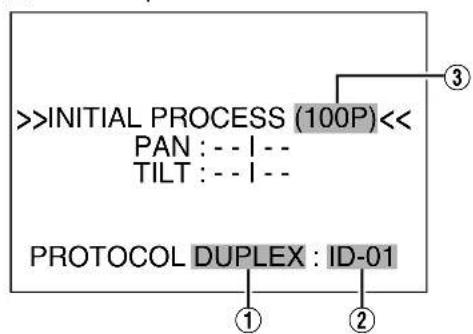
>INITIAL PROCESS (100P)<< PAN : -- I -- TILT : -- I -- PROTOCOL DUPLEX : ID-01 ① ② ③3Check the display on the monitor screen
① Confirm that "DUPLEX" is displayed
② Check that "ID-□□" is displayed and □□ is the correct number
●They match the [VIDEO INPUT] number of RM-P2580.
●Otherwise, reset the machine ID.
③ The indication changes depending on the switch2 setting in the setting switches. (Page 19)
- "ON" →(100P)
- "OFF" →(256P)
Memo :
- When operating a system using the RM-P2580, several cameras can be connected and used on one control signal cable. Consequently, an incorrect switch setting on just a single camera will cause the entire system to work incorrectly.
●The following screen appears when Pelco protocol is used. Check to ensure that the display items are consistent with the system.
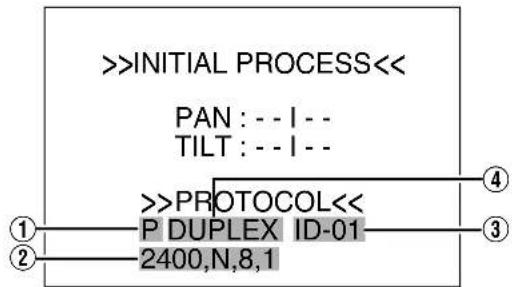
flowchart
graph TD
    A[">>INITIAL PROCESS<<"] --> B["PAN: -- I --"]
    A --> C["TILT: -- I --"]
    B --> D[">>PROTOCOL<<"]
    C --> D
    D --> E["P DUPLEX ID-01"]
    E --> F["2400,N,8,1"]
    style A fill:#f9f,stroke:#333
    style B fill:#ccf,stroke:#333
    style C fill:#ccf,stroke:#333
    style D fill:#cfc,stroke:#333
    style E fill:#fcc,stroke:#333
    style F fill:#fcc,stroke:#333
| 1 Protocol Name P (Pe) | co Protocol |
| 2 Comunication Configuration | |
| Baud Rate 1200, 2400, 4800, 9600 | |
| Parity N, O, E | |
| Data Bit 8 | |
| Stop Bit | 1 |
| 3 Machine ID | ID-00 to ID-255 |
| 4 Topology | Duplex |
Machine ID
Set the machine ID using the combination of dip switch 1 to 8. (The factory default setting is OFF)
| Machine ID | Machine ID setting switch | Machine ID | Machine ID setting switch | Machine ID | Machine ID setting switch | Machine ID | Machine ID setting switch |
| 1 |  | 26 |  | 51 | 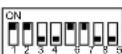 | 76 | 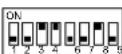 |
| 2 |  | 27 | 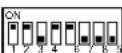 | 52 | 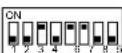 | 77 |  |
| 3 | 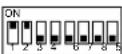 | 28 |  | 53 | 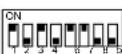 | 78 | 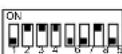 |
| 4 |  | 29 | 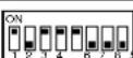 | 54 | 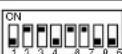 | 79 | 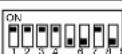 |
| 5 |  | 30 | 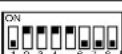 | 55 | 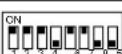 | 80 | 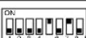 |
| 6 |  | 31 |  | 56 |  | 81 | 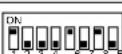 |
| 7 | 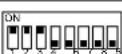 | 32 | 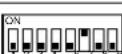 | 57 | 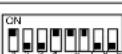 | 82 | 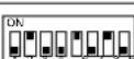 |
| 8 | 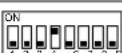 | 33 | 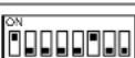 | 58 |  | 83 | 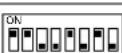 |
| 9 |  | 34 | 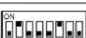 | 59 | 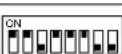 | 84 | 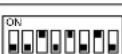 |
| 10 |  | 35 |  | 60 | 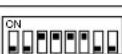 | 85 |  |
| 11 | 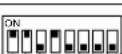 | 36 | 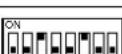 | 61 | 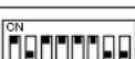 | 86 | 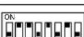 |
| 12 |  | 37 |  | 62 | 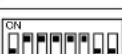 | 87 | 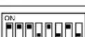 |
| 13 |  | 38 |  | 63 |  | 88 | 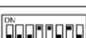 |
| 14 | 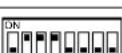 | 39 |  | 64 |  | 89 | 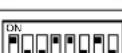 |
| 15 | 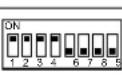 | 40 | 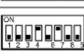 | 65 |  | 90 |  |
| 16 |  | 41 |  | 66 |  | 91 | 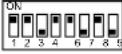 |
| 17 |  | 42 | 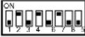 | 67 | 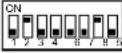 | 92 |  |
| 18 | 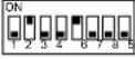 | 43 |  | 68 |  | 93 | 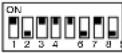 |
| 19 | 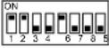 | 44 |  | 69 | 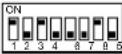 | 94 |  |
| 20 | 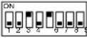 | 45 |  | 70 | 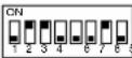 | 95 | 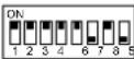 |
| 21 |  | 46 | 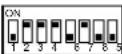 | 71 |  | 96 |  |
| 22 | 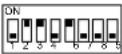 | 47 |  | 72 | 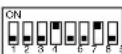 | 97 |  |
| 23 | 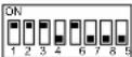 | 48 |  | 73 |  | 98 |  |
| 24 | 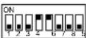 | 49 | 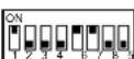 | 74 | 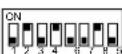 | 99 | 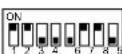 |
| 25 | 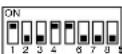 | 50 | 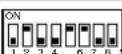 | 75 |  |
Cable Connection

text_image
Provided alarm cable Coaxial cable Power cable Alarm signal cable Control signal cableConnecting the alarm input/alarm output terminals
■Alarm input 1/Alarm output 1 terminal
Connecting alarm input 1/alarm output 1 terminal to external devices such as sensor and buzzer
① Loosen screws on both sides of the terminal block with a flathead screwdriver and remove the terminal block as shown in the diagram below.
Memo :
- Inserting the tip of the screwdriver into the slit of the terminal block will remove the terminal block easily.
② Peel off about 4 mm of the alarm signal cable covering and insert into the terminal.
③ Turn the screws at the side and secure the alarm signal cable.
④ When the alarm signal cable is secured, return the terminal block that was removed in ① to its original position.
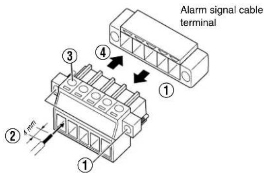
text_image
Alarm signal cable terminal ① ② 4 mm ③ ④■Alarm Input 2 to 6/Alarm Output 2 Terminal

text_image
Provided alarm cable| Pin number | Cable color Signal Name | |
| 1 Brown Alarm input 2 | ||
| 2 | R | e d G |
| 3 Orange Alarm input 3 | ||
| 4 | Y | e l l |
| 5 Green Alarm input 4 | ||
| 6 | Blue | GND |
| 7 | Purple | Alarm input 5 |
| 8 | Gray | GND |
| 9 | White | Alarm input 6 |
| 10 | Black | GND |
| 11 Peach Alarm output 2+ | ||
| 12 | Light green | Alarm output 2- |
[Non-Text]
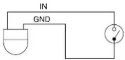
■Alarm input terminal
Connects to sensors such as infrared sensors, door sensors, metal sensors and manual switches.
- To prevent noise from entering the internal circuit, supply non-voltage contact signal to the alarm input terminal.
- Do not supply voltage.
- When the contact is short (MAKE) or open (BREAK) on the menu, you can set it to Alarm.
●Supply such that the alarm signal continues for at least more than 200 ms. The alarm signal may not be recognized if it is less than 200 ms.
■Alarm output terminal
Connects to alarm devices such as alarm, indicator, light or buzzer
- Alarm output 1 terminal is the contact output. When there is an alarm, the OUT1 NOP-COM will become short (MAKE) and OUT1 NCL-COM will become open (BREAK).

Rating:
Max. applied voltage
:DC 30 V or AC 24 V
Max. applied current
:1 A
Contact life :100,000 times
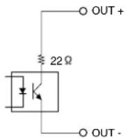
- Alarm output 2 terminal is an open collector output insulated with photo coupler.
●During an alarm, it is ON. - As this terminal is polarized, be sure to connect it such that the voltage of the + terminal is higher than that of the - terminal.
- It will be damaged if reverse voltage is supplied.

Rating:
Max. applied voltage :DC 20 V
Max. driving current :25 mA
Memo :
- When alarm is switched ON/OFF, a sound will be produced from the alarm output 1 relay. If you mind the sound, use alarm output 2 terminal. However, be sure not to exceed the rating.
Connecting the coaxial cable
Connecting a RG-59 coaxial cable.
Treat the extremity of the coaxial cable as shown below before connecting it.

text_image
Polyethylene Core wire 7 mm 8 mm 4 mm Mesh shield wire Insulating tapeMemo :
- If a RG-11 coaxial cable is used it cannot be connected directly to the terminal board. To use such a cable, connect a RG-59 cable to the camera and then connect the RG-11 cable to the RG-59 cable.
- Turn the mesh shield wire over and insulate it so that it will not fray and cause short circuit.
Cable Connection (continued)
Connecting the control signal cable
The maximum connection distance with RM-P2580 is 1,200 m. (Multiple cameras can be connected on one cable for RM-P2580 but the total length of the cable must be within 1,200 m.)
■Connect the cable to the terminal block
① Loosen screws on both sides of the terminal block with a flathead screwdriver and remove the terminal block as shown in the diagram below.
Memo :
- Inserting the tip of the screwdriver into the slit of the terminal block will remove the terminal block easily.
② Peel off about 4 mm of the control signal cable covering and insert into the terminal.
③ Turn the screws on the sides and secure the control signal cable.
④ When the control signal cable is secured, return the terminal block that was removed in ① to its original position.

text_image
Control signal cable terminal ① ② 4 mm ③ ④■Overall view of control signal cable connection
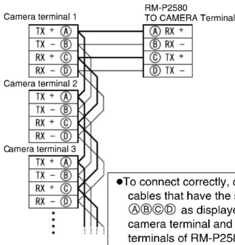
text_image
Camera terminal 1 TX + A TX - B RX + C RX - D Camera terminal 2 TX + A TX - B RX + C RX - D Camera terminal 3 TX + A TX - B RX + C RX - D RM-P2580 TO CAMERA Terminal A RX + B RX - C TX + D TX - ●To connect correctly, c cables that have the s A B C D as displayed camera terminal and t terminals of RM-P258Memo :
- We recommend the use of paired cables or twisted pair cables used in Ethernet rather than 0.61-4-core (2 pairs) cables.
- Thickness of the cable is 0.4mm to 1.3mm .
- Arrange the control signal cables such that the TX+ and TX-signals and RX+ and RX-signals are pairs.
Connecting the power cable
Connecting AC 24 V power
Connect an AC 24 V power cable to AC 24 V power supply. To prevent connection mistake or cable dislocation, we recommend the use of a lug board to connect to a AC24V terminal.
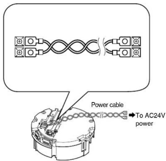
text_image
Power cable To AC24V powerWhen using 2-core VVF (Vinyl-insulated vinyl-sheath cable), the connection distance is as follows: (Reference value)
| Maximum connection distance | 100 m 260 m 410 m | 500 m | ||
| Conductor diameter (AWG No.) | ø1.4 mm (15) and above | ø2.3 mm (11) and above | ø2.9 mm (9) and above | ø3.2 mm (8) and above |
Note :
●To supply AC 24 V, use a AC 24 V supplying power unit that is insulated from AC 230 V line.
- If thin cables are used, the resistance of the cables will be high and a significant voltage drop will occur when the camera is at its maximum power consumption (when pan, tilt and zoom operates at the same time). Either use a thick cable with low resistance or place the power supply near to the camera and shorten the length of the cable to restrict the voltage drop at the rated current of camera to below 10% . If voltage drops during operation, the camera may experience unstable performance and be unable to call up the preset position correctly.
- Do not connect an AC 24 V cable to AC 230 V power supply. The camera will be damaged. If the wrong cable is connected, the internal circuit will be damaged. Stop using the camera and send it to your nearest JVC dealer for repair. (Chargeable)
●Turn on the power only after the connection for all the devices is complete.
Camera Installation Procedures
Install the camera with the following procedures.
Preparation (Page 26)

Mounting the camera (Page 28)

Cable Connection (Page 28)
Mounting the Camera
Setting Up the Wall
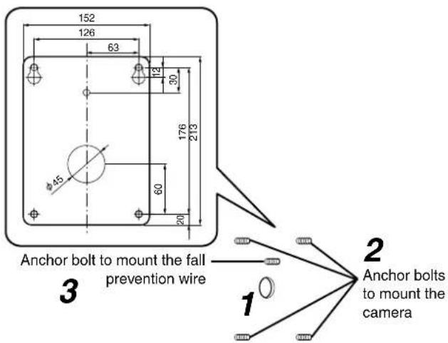
1 Make holes in the wall
Make holes (ø 45 mm) for the connecting cables to pass through.
Note :
- Check the strength of the wall. A less firm wall may cause the unit to fall.
2 Install the anchor bolts for mounting the camera
Install 4 anchor bolts (M8×35 mm and above) to mount the camera.
3 Install the anchor bolt for mounting the fall prevention wire
Install the anchor bolt to mount the fall prevention wire 30 mm below the center of the upper two anchor bolts that are used to mount the camera.
text_image
152 126 63 112 30 176 213 φ45 60 20 Anchor bolt to mount the fall prevention wire Anchor bolts to mount the camera 3 1 2 14Pull the cables from the hole in the wall
Pull the power cable, BNC cable, control signal cable and alarm signal cable from the wall.

text_image
Coaxial cable Power cable Control signal cable Alarm signal cableSetting Up the Camera
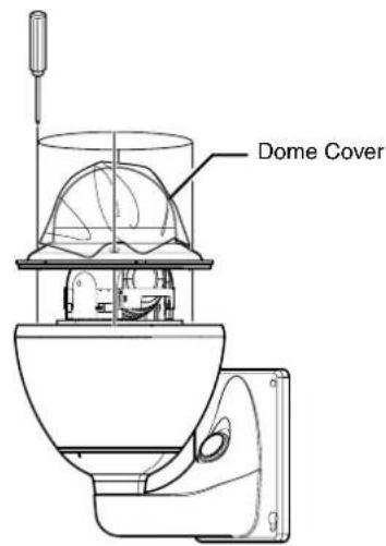
1 Remove the dome cover and take out the cushioning material
① Loosen the screws (x4) and remove the dome cover from the camera.
text_image
Dome Cover② Remove the cushioning material.
③ Remove the tape on the lens section.
④ Remove the lens cap.
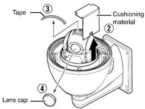
text_image
Tape ③ Cushioning material ② Lens cap ④2 Set the switch (Page 30, 31)
- Configure the setting switch and machine ID switch according to the system.
- When installing the heater at an unrequired location, turn off the switch of the heater.

text_image
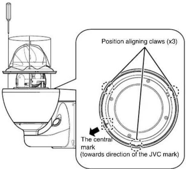
Heater power switch Setting Switch Machine ID switch Option Switch3Mount the dome cover to the camera
① Use the screws (x4) to mount the dome cover to the camera. As a guide, install three claws of the dome cover and the central mark. Install such that the central mark appears above the JVC mark of the camera.
text_image
Position aligning claws (x3) The central mark (towards direction of the JVC mark)Note :
- Check that there is no dirt or dust inside the dome cover before mounting.
- When installing on a rainy day, ensure that raindrops do not enter the interior.
- When mounting the dome cover, temporarily secure the 4 screws and then tighten.
- As a guide, tighten the screws to 0.5N·m to 1N·m (5kgf·cm to 10kgf·cm). If the tightening is loose, the dome cover may fog due to water seepage.
4Remove the cable connection cap
Remove the cap on the arm of the camera.
5Pull out the cables from the cable connection hole
Pull the cables from the camera unit (except the fall prevention wire) out from the cable connection hole.

text_image
Cable connection cap 4 5Camera Installation Procedures (continued)
Mounting the Camera
1 Mount the fall prevention wire
●Mount the fall prevention wire of the camera to the fall prevention wire anchor bolt that was installed earlier.
- Secure the fall prevention wire tightly with a nut and washer.
2 Pull out the cables (from the wall) from the cable connection hole
3Mount the camera to the wall
●Mount the camera to the camera anchor bolts that were installed earlier.
- Secure the camera tightly with a nut and washer.
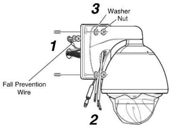
text_image
1 Fall Prevention Wire 2 3 Washer NutNote :
- The mass of this product is approximately 5.5 kg. Pay careful attention during mounting to prevent it from falling off.
- For safety reasons, hold the arm during installation.
●After installing, paint the nuts and washers to prevent corrosion.
Memo :
●To remove the camera, follow the reverse procedures.
Cable Connection
1 Connecting the coaxial cable (BNC)
① Lower the protection cover and connect the connectors.
② After connection is complete, cover the connectors with the protection cover.
③ Wind the waterproof tape (cohesive) from the top of the protection cover.
④ Push the cables into the arm of the camera.
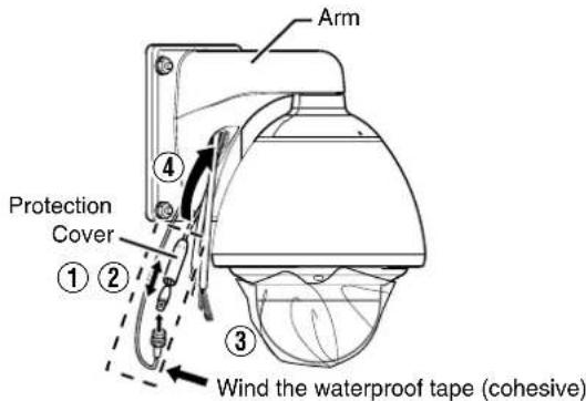
text_image
Arm Protection Cover ① ② ③ Wind the waterproof tape (cohesive)2Connecting the power cable
① Connect the power cable.
② After the connection is complete, wind the waterproof tape (cohesive).
③ Push the cables into the arm of the camera.

text_image
Arm ③ ① ② Wind the waterproof tape (c)Note :
●The AC 24 V power supply must be isolated from the primary line. (ISOLATED POWER ONLY)
- In order to prevent an excessive current flow through the power supply wire or camera due to a short circuit, a fuse must be installed in the power supply line.
3Connecting the alarm cable and control signal cable
① Connect the cables.
② After the connection is complete, wind the waterproof tape (cohesive).
③ Push the cables into the arm of the camera.
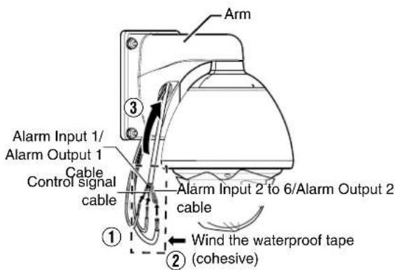
text_image
Arm Alarm Input 1/ Alarm Output 1 Cable Control signal cable ① ② Alarm Input 2 to 6/Alarm Output 2 cable Wind the waterproof tape (cohesive)Note :
- For cables that are not used, be sure to wrap the ends individually with insulating tape.
- For safety reasons, turn on the power only after all the connection is complete.
4Mount the cap
5Seal the cable connection hole and around the mounting surface of the camera with waterproof seal (GE silicone).
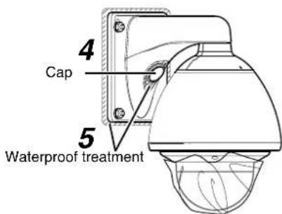
text_image
4 Cap 5 Waterproof treatmentNote :
- Ensure that waterproof treatment is performed.
Otherwise, the camera may malfunction due to rain water seepage. - Use GE silicone or its equivalents as the sealing material.
6Remove the dome cover protective sheet

text_image
Dome cover protective sheetSwitch Setting
text_image
Setting Switch Option Switch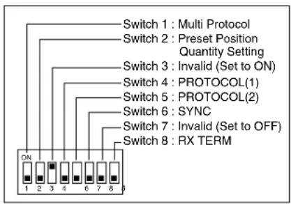
text_image
Switch 1 : Multi Protocol Switch 2 : Preset Position Quantity Setting Switch 3 : Invalid (Set to ON) Switch 4 : PROTOCOL(1) Switch 5 : PROTOCOL(2) Switch 6 : SYNC Switch 7 : Invalid (Set to OFF) Switch 8 : RX TERMSetting Switch
Before mounting the camera, configure the setting switch in the position indicated in the illustration.
The setting differs according to the system used.
●Multi Protocol (Switch 1)
| JVC Protocol OFF | |
| Pelco Protocol ON |
- Preset Position Quantity Setting (Switch 2) *1
| 100 positions | OFF |
| 256 positions (when using Pelco protocol) | ON |
Memo :
- When Switch 1 is set to ON (Pelco protocol), the number of preset positions becomes 256 regardless of the settings of Switch 2.
- Switch 3
This switch must be set to ON.
- PROTOCOL(1) (Switch 4) *1
Selects whether a single camera or multiple cameras are controlled in a system.
Set PROTOCOL(1) to multi DROP when connecting multiple cameras in series.
| Point to point OFF | |
| Multi DROP (when using the RM-P2580) ON |
(Initial set: OFF)
*When set to multi DROP, be sure to set the Machine ID of each camera. (Page 20)
●PROTOCOL(2) (Switch 5) *1
Set this switch according to the communication protocol used when controlling the cameras.
| Duplex (when using the RM-P2580) OFF | |
| Simplex) | ON |
(Initial set: OFF)
●SYNC (Switch 6)
When this switch is set to ON, the vertical sync of the camera becomes locked to the frequency of the AC power line.
| INT | OFF |
| LL | ON |
(Initial set: OFF)
*LL mode: 50 Hz area only.
- Switch 7
This switch must be set to OFF.
●RX TERM (Switch 8)
This switch sets whether or not the section between control signal terminals RX + and RX - is to be terminated (with a resistance of 110 Ω).
| Open | OFF |
| Terminated (110 Ω) | ON |
(Initial set: OFF)
When the system in which this camera is used is a multidrop system (RS-485 system), set only the camera located at the extreme end of the control signal cables to "Terminated" and set the other cameras to "Open".
※1: The settings of Switches 2, 4, and 5 are enabled only when Switch 1 is turned OFF (JVC protocol).
Option Switch
Configure this switch when Pelco protocol is used.
●Protocol Selection (Switches 1, 2, 3)
| Switch 1 | Switch 2 | Switch 3 | |
| Pelco Protocol | OFF | OFF | OFF |
●Parity Selection (Switches 4, 5)
| Switch 4 | Switch 5 | |
| NONE | OFF | OFF |
| NONE | ON | OFF |
| EVEN | OFF | ON |
| ODD | ON | ON |
●Baud Rate Selection (Switches 6, 7, 8)
| Switch 6 | Switch 7 | Switch 8 | |
| 1200 bit/s | OFF | OFF | OFF |
| 2400 bit/s | ON | OFF | OFF |
| 4800 bit/s | OFF | ON | OFF |
| 9600 bit/s | ON | ON | OFF |
Machine ID Setting Switch
When controlling the system via a multi DROP system such as RM-P2580, a machine ID will be attached to the system to differentiate it from other connected cameras.
Match the machine ID with the [VIDEO INPUT] number of RM-P2580.
Memo :
- For details on the Machine ID setting switch, please refer to [Machine ID] (Page 21).
text_image
Machine ID Setting Switch■Machine ID Confirmation Procedures
1 Output the image of the camera to be checked on the monitor
2Turn on the power of the camera
●The camera initializes and the following screen is displayed on the monitor.
■When JVC protocol is used
text_image
>INITIAL PROCESS (100P)<< PAN : -- | -- TILT : -- | -- PROTOCOL DUPLEX : ID-01 ① ② ③3Check the display on the monitor screen
① Confirm that "DUPLEX" is displayed
② Check that "ID-□□" is displayed and □□ is the correct number
●They match the [VIDEO INPUT] number of RM-P2580.
●Otherwise, reset the machine ID.
③ The indication changes depending on the switch2 setting in the setting switches. (Page 30)
- “ON” →(100P)
- “OFF” (256P)
Memo :
- When operating a system using the RM-P2580, several cameras can be connected and used on one control signal cable. Consequently, an incorrect switch setting on just a single camera will cause the entire system to work incorrectly.
●The following screen appears when Pelco protocol is used. Check to ensure that the display items are consistent with the system.

flowchart
graph TD
    A[">>INITIAL PROCESS<<"] --> B["PAN : -- I --"]
    A --> C["TILT : -- I --"]
    B --> D[">>PROTOCOL<<"]
    C --> D
    D --> E["P DUPLEX ID-01"]
    E --> F["2400,N,8,1"]
    style A fill:#f9f,stroke:#333
    style B fill:#ccf,stroke:#333
    style C fill:#ccf,stroke:#333
    style D fill:#cfc,stroke:#333
    style E fill:#fcc,stroke:#333
    style F fill:#cff,stroke:#333
| 1 Protocol Name P (Pe)co Protocol) | |
| 2 Comunication Configuration | |
| Baud Rate 1200, 2400, 4800, 9600 | |
| Parity N, O, E | |
| Data Bit 8 | |
| Stop Bit 1 | |
| 3 Machine ID | ID-00 to ID-255 |
| 4 Topology | Duplex |
Cable Connection
Connecting the alarm signal cable
■Alarm input signal
Connects to sensors such as infrared sensors, door sensors, metal sensors and manual switches.
- To prevent noise from entering the internal circuit, supply non-voltage contact signal to the alarm input signal.
- Do not supply voltage.
- When the contact is short (MAKE) or open (BREAK) on the menu, you can set it to Alarm.
●Supply such that the alarm signal continues for at least more than 200 ms. The alarm signal may not be recognized if it is less than 200 ms.

■Alarm output signal
Connects to alarm devices such as alarm, indicator, light or buzzer
- Alarm output 1 signal is the contact output. When there is an alarm, the OUT1NOP-COM will become short (MAKE) and OUT1NCL-COM will become open (BREAK).
Rating:
Max. applied voltage
:DC 30 V or AC 24 V
Max. applied current:1 A
Contact life :100,000 times
- Alarm output 2 signal is an open collector output insulated with photo coupler.
●During an alarm, it is ON. - As this cable is polarized, be sure to connect it such that the voltage of the + terminal is higher than that of the - terminal.
- It will be damaged if reverse voltage is supplied.
Rating:
Max. applied voltage: DC 20 V
Max. driving current:25 mA
Memo :
- When alarm is switched ON/OFF, a sound will be produced from the alarm output 1 relay. If you do not want to hear the sound, use the alarm output 2 cable. However, be sure not to exceed the rating.
Connecting the control signal cable
The maximum connection distance with RM-P2580 is 1,200 m. (Multiple cameras can be connected on one cable for RM-P2580 but the total length of the cable must be within 1,200 m.)
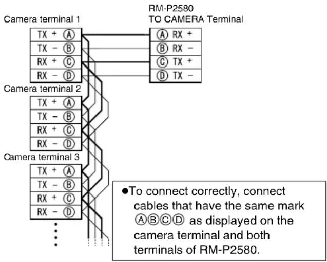
text_image
Camera terminal 1 TX + A TX - B RX + C RX - D Camera terminal 2 TX + A TX - B RX + C RX - D Camera terminal 3 TX + A TX - B RX + C RX - D RM-P2580 TO CAMERA Terminal A RX + B RX - C TX + D TX - ●To connect correctly, connect cables that have the same mark A B C D as displayed on the camera terminal and both terminals of RM-P2580.Memo :
- We recommend the use of paired cables or twisted pair cables used in Ethernet rather than 0.61-4-core (2 pairs) cables.
- Thickness of the cable is 0.4mm to 1.3mm .
- Arrange the control signal cables such that the TX+ and TX-signals and RX+ and RX-signals are pairs.
Connecting the power cable
Connecting AC 24 V power
Connect an AC 24 V power cable to AC 24 V power supply.
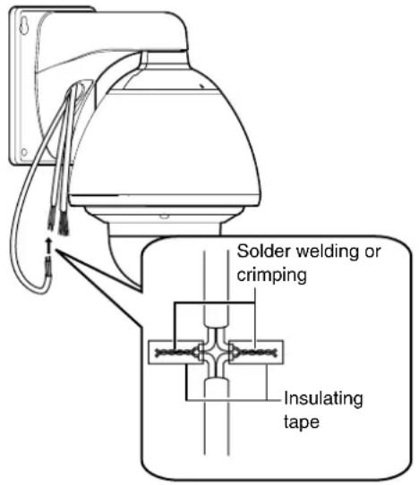
text_image
Solder welding or crimping Insulating tapeWhen using 2-core VVF (Vinyl-insulated vinyl-sheath cable), the connection distance is as follows: (Reference value)
| Conductor diameter | AWG#16 | AWG#14 | AWG#12 | AWG#10 |
| Maximum connection distance | 40 m 70 | m 110 m | 180 m |
Note :
●To supply AC 24 V, use a AC 24 V supplying power unit that is insulated from AC 230 V line.
- If thin cables are used, the resistance of the cables will be high and a significant voltage drop will occur when the camera is at its maximum power consumption (when pan, tilt and zoom operates at the same time). Either use a thick cable with low resistance or place the power supply near to the camera and shorten the length of the cable to restrict the voltage drop at the rated current of camera to below 10% . If voltage drops during operation, the camera may experience unstable performance and be unable to call up the preset position correctly.
- Do not connect an AC 24 V cable to AC 230 V power supply. The camera will be damaged.
- If the wrong cable is connected, the internal circuit will be damaged. Stop using the camera and send it to your nearest JVC dealer for repair. (Chargeable)
- Turn on the power only after the connection for all the devices is complete.
Setting Procedures
You can call out the camera menu and set functions from the remote control for systems that use the remote control unit.
Memo :
●The onscreen displays used in this manual are basically from TK-C686E/TK-C686WPE except in special cases.
Setting camera menu from RM-P2580
Memo :
- Do not operate the RM-P2580 menu until the camera has completed initialization.
- Refer to the RM-P2580 Instruction Manual together with this manual.
- Menus described in this item are color menus. Camera menus are indicated in yellow, and remote control menus are indicated in white. For the RM-P2580 system menu, refer to the RM-P2580 Instruction Manual.
text_image
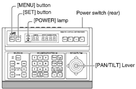
[MENU] button [SET] button [POWER] lamp Power switch (rear) LENS CAMERA/DOTIONS PAN/TILT [PAN/TILT] Lever1 Tum "ON" the power switch at the rear
The [POWER] lamp lights up.
2Press the [MENU] button for 3 seconds.
●The [MENU] button lamp lights up.
●The [SETUP] screen at the remote control is displayed from [MONITOR OUTPUT-1].
3Shift down the [PAN/TILT] lever and move the cursor (▷) to the [CAMERA..] item.
- When the lever is pressed upwards (▲), the cursor moves up.
- When the lever is pressed downwards (▼), the cursor moves down.
Cursor
![JVC TK-C685WPE - 3Shift down the [PAN/TILT] lever and move the cursor (▷) to the [CAMERA..] item. - 1](/content/2026/06/1199146/images/27c6ef52c6a75c2d07efd5efdf163d2ffa246fd4a7cec75bc520296f7c7818bb.jpg)
text_image
SETUP POSITION SETUP. . CAMERA. . CONTROL UNIT. .[SETUP] screen
![JVC TK-C685WPE - 3Shift down the [PAN/TILT] lever and move the cursor (▷) to the [CAMERA..] item. - 2](/content/2026/06/1199146/images/7bc0b82292bdf80f86c9c2db6e87b80c96b22af83373e5645838f39f4ddfb14c.jpg)
text_image
MENU LANGUAGE ENGLISH CAMERA FUNCTION1 CAMERA FUNCTION2.. CAMERA TITLE/ALARM.. CAMERA ALC.. CAMERA VIDEO.. AUTO PAN/PATROL/TRACE.. POS.FUNCTION SET.. FACTORY SETTINGS..[MENU] screen
4Press the [SET] button
●The item and screen are displayed.
- Items with “..” at the end indicate they have submenus.
5 Shift the [PAN/TILT] lever up and down to select items
6Press the [SET] button
- Press the lever to the left (◀) to minimize the numbers.
- Press the lever to the right (▶) to maximize the numbers.
Change mark
![JVC TK-C685WPE - 6Press the [SET] button - 1](/content/2026/06/1199146/images/9804ae882ca6b8797f094073464670f09a8692abc7c3535429d58270611d266c.jpg)
text_image
CAMERA FUNCTION1 V. PHASE 1 POS. TITLE LOC. UP-L PRIVATE MASK.. MANUAL DISPLAY ON HOME M. DETECT OFF D.ZOOM MAX X2 STABILIZER OFFExample of submenu screen
Memo :
- A change mark ( ) as shown in the left diagram will be displayed when the item setting is changed.
7Press the [MENU] button
When the item has been set, press the [MENU] button to return to the top menu screen.
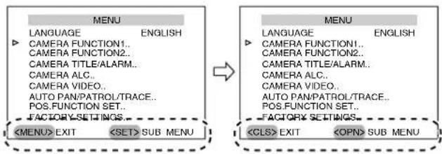
Menu Display When Using Pelco Protocol
When using this unit with Pelco protocol (Page 19) (Page 30), you will see a different menu screen display.
Control Button Display
When the menu screen is in the full mode, the control button display at the bottom of the screen changes.
●[MENU]→[CLS]
- [SET]→[OPN]
flowchart
graph LR
    A["MENU"] --> B["<MENU> EXIT"]
    A --> C["<SET> SUB MENU"]
    D["MENU"] --> E["<CLS> EXIT"]
    D --> F["<OPN> SUB MENU"]
    A --> G["→"]
    D --> H["→"]
Menu Display
These that are displayed as [HOME] on the menu screen are changed to [POS1].
| Normal Display Menu Display | When Using Pelco Protocol |
| [HOME] [POS1] | |
| [HOME M.Detect] [POS1 M.Detect] | |
| [HOME M.Detect (ALARM)] | [POS1 M.Detect (ALARM)] |
| [HOME M.Detect (TRACKING)] | [POS1 M.Detect (TRACKING)] |
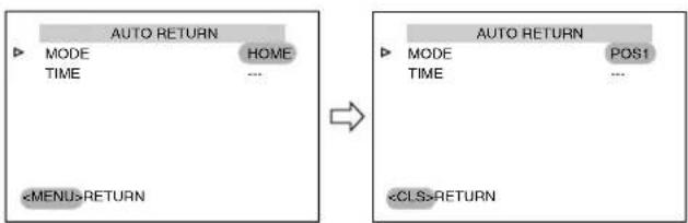
• [AUTO RETURN] screen (Page 41)
Setting value changes
●[HOME]→[POS1]
flowchart
graph LR
    A["AUTO RETURN"] --> B["MODE"]
    A --> C["HOME"]
    A --> D["TIME"]
    A --> E["..."]
    F["<MENU>RETURN"] --> G["AUTO RETURN"]
    G --> H["MODE"]
    G --> I["POS1"]
    G --> J["TIME"]
    G --> K["..."]
    L["<CLS>RETURN"] --> M["AUTO RETURN"]
    M --> N["MODE"]
    M --> O["POS1"]
    M --> P["TIME"]
    M --> Q["..."]
• [ALARM INPUT] screen (Page 42)
Setting value changes
●[OFF, HOME, POS1 to POS99]→ [OFF, POS1 to POS32, POS35 to POS82]

text_image
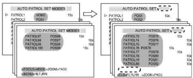
ALARM INPUT ▶ INPUT1 OFF INPUT2 HOME INPUT3 OFF INPUT4 OFF INPUT5 OFF INPUT6 OFF• [AUTO PATROL SET] screen (Page 47)
Deletion of item
- [MODE1 to MODE3]→ Deleted (only [MODE1] is available)
Setting value changes
●[OFF, HOME, POS1 to POS99]→ [OFF, POS1 to POS32, POS35 to POS82, POS100 to POS256]
flowchart
graph TD
    A["AUTO PATROL SET MODE1"] --> B["PATROL1 HOME 10s"]
    A --> C["PATROL2 POS1 10s"]
    D["AUTO PATROL SET MODE1"] --> E["PATROL97 POS56 10s"]
    D --> F["PATROL98 POS57 10s"]
    D --> G["PATROL99 POS58 10s"]
    D --> H["PATROL100 POS59 10s"]
    I["AUTO PATROL SET MODE1"] --> J["POSLRETURN <ZOOM>PAGE"]
    K["AUTO PATROL SET MODE1"] --> L["POSLRETURN <ZOOM>PAGE"]
    M["AUTO PATROL SET MODE1"] --> N["POSLRETURN <ZOOM>PAGE"]
    O["AUTO PATROL SET MODE1"] --> P["POSLRETURN <ZOOM>PAGE"]
Flow of Menu Screens
RM-P2580
The menu screen consists of the following flow. (For details, see the reference page for each item)

flowchart
graph TD
    A["Normal screen"] --> B["SETUP POSITION SETUP... CAMERA... CONTROL UNIT..."]
    A --> C["MENU LANGUAGE ENGLISH CAMERA FUNCTION1... CAMERA FUNCTION2... CAMERA TITLE/ALARM... CAMERA ALC... CAMERA VIDEO... AUTO PAN/PATROL/TRACE... POS.FUNCTION SET... FACTORY SETTINGS... SUB MENU EXIT"]
    B --> D["(Page 38)"]
    D --> E["CAMERA FUNCTION1 V.PHASE ... POS. TITLE LOC. UP.L PRIVATE MASK MANUAL DISPLAY ON HOME M.Detect OFF D ZOOM MAX X2 STABILIZER OFF <MENU> RETURN"]
    E --> F["ON"]
    F --> G["(STABILIZER LEVEL NORMAL <MENU>RETURN"]
    G --> H["(Page 40)"]
    H --> I["STABILIZER LEVEL NORMAL <MENU>RETURN"]
    I --> J["(Page 41) AUTO RETURN MODE OFF TIME ... <MENU>RETURN"]
    J --> K["(TK-C686E/TK-C686WPE only"]
    C --> L["(Page 42)"]
    L --> M["CAMERA FUNCTION2 FLIP DIGITAL VAR P/T SPEED ON EASY AF OFF AF FOR IR OFF TILT LIMIT 0' M.PAN LIMIT OFF AUTO RETURN. <MENU> RETURN"]
    M --> N["ON"]
    N --> O["(Page 44)"]
    O --> P["CAMERA TITLE / ALARM CAM.TITLE EDIT... AREA DISPLAY OFF ALM.TITLE SIZE DOUBLE ALM.TITLE COLOUR WHITE ALARM TITLE EDIT... ALARM INPUT... ALARM OUTPUT. <MENU> RETURN <SET> SUB MENU"]
    P --> Q["(Page 45)"]
    Q --> R["B&W/COLOUR MODE B&W MODE COLOUR LEVEL ... B&W A. TIME ... LIGHT TYPE NORMAL <MENU>RETURN"]
    R --> S["(Page 46)"]
    S --> T["CAMERA ALC MONITOR TYPE CRT DVR SAVE MODE OFF COLOUR LEVEL NORMAL ENHANCE LEVEL NORMAL SETUP DN.R MODE OFF SEC MODE OFF <MENU>RETURN"]
    T --> U["(Page 47)"]
    U --> V["AUTO PAN/PATROL/TRACE AUTO PAN SET AUTO PATROL SET AUTO TRACE SET A. PANTRACE VIDEO RM.A.PAN KEY A.PAN RM.A.PATROL KEY A.PATROL <MENU>RETURN <SET> SUB MENU"]
    V --> W["(Page 53)"]
    W --> X["FACTORY SETTINGS CANCEL CLEAR (WO POS.TITLE) CLEAR(ALL) <MENU>RETURN <SET>RETURN"]
    X --> Y["(Page 50)"]
    Y --> Z["POS FUNCTION SET HOME POSITION TITLE... AUTO IRIS MODE OFF EXDR MODE OFF BLC MODE OFF W.BALANCE ATW-W R GAIN ... B GAIN <MENU>RETURN <SET> SUB MENU"]
    Z --> AA["(Page 51)"]
    AA --> AB["POS FUNCTION SET HOME POSITION TITLE... POSITION VIDEO SCENE A <MENU>RETURN <SET> SUB MENU"]
    AB --> AC["(Page 72)"]
    AC --> AD["POP. TITLE EDIT HOME 0123456789 ABCDEFGHJKLMNO PQRSTUVWXYZabcdefghijklmnopqrstuvwxyzAOUEIOUCNabelou m100aediaeaoughB12... : : / () => CLR CANCEL [+"] -] INS DEL W T <MENU>RETURN <SET> CHAR.SET]
    AC --> AE["(Page 73)"]
    AE --> AF["POSITION VIDEO SCENE A IRIS MODE AUTO EXDR MODE OFF EXDR LEVEL ... BLC MODE OFF W.BALANCE ATW-W R GAIN ... B GAIN <MENU>RETURN"]
※ When preset position is set to 256

flowchart
graph TD
    A["ALARM"] --> B["PRIVATE MASK"]
    B --> C["ON"]
    C --> D["MASK MODE"]
    D --> E["MASK EDIT No 1"]
    E --> F["<MENU>RETURN"]
    G["TRACKING"] --> H["HOME M. DETECT(ALARM)"]
    H --> I["TYPE: NORMAL\nAREA EDIT, TIME: 5s\nDEMONSTRATION, <MENU>RETURN"]
    I --> J["MOTION DETECT AREA EDIT"]
    J --> K["<MENU>RETURN"]
    L["TRACKING"] --> M["HOME M. DETECT(TRACKING)"]
    M --> N["TYPE: NORMAL\nRESTART TIME OFF\nDEMONSTRATION, <MENU>RETURN"]
    N --> O["DEMONSTRATION(ALARM)"]
    O --> P["<MENU>RETURN"]
    Q["ALARM OUTPUT"] --> R["ALARM INPUT"]
    R --> S["Polarity: ..."]
    S --> T["TIME: ..."]
    T --> U["PRIORITY: ..."]
    U --> V["<MENU>RETURN"]
    W["TRACKING"] --> X["HOME M. DETECT(TRACKING)"]
    X --> Y["TYPE: NORMAL\nRESTART TIME OFF\nDEMONSTRATION, <MENU>RETURN"]
    Y --> Z["MOTION DETECT (ARBI) EDIT"]
    Z --> AA["<MENU>RETURN"]
    AB["TRACKING"] --> AC["HOME M. DETECT(TRACKING)"]
    AC --> AD["TYPE: NORMAL\nRESTART TIME OFF\nDEMONSTRATION, <MENU>RETURN"]
    AD --> AE["MOTION DETECT (ARBI) EDIT"]
    AE --> AF["<MENU>RETURN"]
    AG["TRACKING"] --> AH["HOME M. DETECT(TRACKING)"]
    AH --> AI["TYPE: NORMAL\nRESTART TIME OFF\nDEMONSTRATION, <MENU>RETURN"]
    AI --> AJ["MOTION DETECT (ARBI) EDIT"]
    AJ --> AK["<MENU>RETURN"]
    AL["TRACKING"] --> AM["HOME M. DETECT(TRACKING)"]
    AM --> AN["TYPE: NORMAL\nRESTART TIME OFF\nDEMONSTRATION, <MENU>RETURN"]
    AN --> AO["MOTION DETECT (ARBI) EDIT"]
    AO --> AP["<MENU>RETURN"]
    AQ["TRACKING"] --> AR["HOME M. DETECT(TRACKING)"]
    AR --> AS["TYPE: NORMAL\nRESTART TIME OFF\nDEMONSTRATION, <MENU>RETURN"]
    AS --> AT["MOTION DETECT (ARBI) EDIT"]
    AT --> AU["<MENU>RETURN"]
    AV["TRACKING"] --> AW["HOME M. DETECT(TRACKING)"]
    AW --> AX["TYPE: NORMAL\nRESTART TIME OFF\nDEMONSTRATION, <MENU>RETURN"]
    AX --> AY["MOTION DETECT (ARBI) EDIT"]
    AY --> AZ["<MENU>RETURN"]
    BA["TRACKING"] --> BB["HOME M. DETECT(TRACKING)"]
    BB --> BC["TYPE: NORMAL\nRESTART TIME OFF\nDEMONSTRATION, <MENU>RETURN"]
    BC --> BD["MOTION DETECT (ARBI) EDIT"]
    BD --> BE["<MENU>RETURN"]
    BF["TRACKING"] --> BG["HOME M. DETECT(TRACKING)"]
    BG --> BH["TYPE: NORMAL\nRESTART TIME OFF\nDEMONSTRATION, <MENU>RETURN"]
    BH --> BI["MOTION DETECT (ARBI) EDIT"]
    BI --> BJ["<MENU>RETURN"]
    BK["TRACKING"] --> BL["HOME M. DETECT(TRACKING)"]
    BL --> BM["TYPE: NORMAL\nRESTART TIME OFF\nDEMONSTRATION, <MENU>RETURN"]
    BM --> BN["MOTION DETECT (ARBI) EDIT"]
    BN --> BO["<MENU>RETURN"]
    BP["TRACKING"] --> BQ["HOME M. DETECT(TRACKING)"]
    BQ --> BR["TYPE: NORMAL\nRESTART TIME OFF\nDEMONSTRATION, <MENU>RETURN"]
    BR --> BS["MOTION DETECT (ARBI) EDIT"]
    BS --> BT["<MENU>RETURN"]
    BU["TRACKING"] --> BV["HOME M. DETECT(TRACKING)"]
    BV --> BW["TYPE: NORMAL\nRESTART TIME OFF\nDEMONSTRATION, <MENU>RETURN"]
    BW --> BX["MOTION DETECT (ARBI) EDIT"]
    BX --> BY["<MENU>RETURN"]
    CA["TRACKING"] --> CB["HOME M. DETECT(TRACKING)"]
    CB --> CC["TYPE: NORMAL\nRESTART TIME OFF\nDEMONSTRATION, <MENU>RETURN"]
    CC --> CD["MOTION DETECT (ARBI) EDIT"]
    CD --> CE["<MENU>RETURN"]
    CF["TRACKING"] --> CG["HOME M. DETECT(TRACKING)"]
    CG --> CH["TYPE: NORMAL\nRESTART TIME OFF\nDEMONSTRATION, <MENU>RETURN"]
    CH --> CI["MOTION DETECT (ARBI) EDIT"]
    CI --> CE
    CJ["AIRM INPUT"] --> CK["Polarity: ..."]
    CK --> CL["TIME: ..."]
    CL --> CD
    CD --> CD
LANGUAGE Setting
(● indicates the default value)
| Item Setting value Functions and settings | ||
| LANGUAGE | ●ENGLISHFRENCHGERMANSPANISHITALIAN | For selecting the menu's display language. |
CAMERA FUNCTION1 screen
(● indicates the default value)
| Item Setting value Functions and settings | ||
| V.PHASE | -156 to 0 to 156(● 0) | This adjusts the vertical synchronization to those of other cameras when a selector switch for the synchronizing system on the Ceiling Mount is at LL. (50 Hz power region only.) |
| POS.TITLE LOC. | ●UP-LDOWN-LUP-CDOWN-CUP-RDOWN-R | This item sets the display position of the position title and area title.UP-L : Display at the top left of the screen.DOWN-C : Display at the bottom center of the screen.DOWN-L : Display at the bottom left of the screen.UP-R : Display at the top right of the screen.UP-C : Display at the top center of the screen.DOWN-R : Display at the bottom right of the screen. |
| PRIVATE MASK.. | —This function allows you to set and mask areas that you do not wish to display in the recorded screen.The selected areas move together with the pan, tilt and zoom operations.[Private Mask Setting] ( page 54) | |
| MODE | ●OFFON | This item sets the ON/OFF setting of the Private Mask.OFF : Private Mask is disabled.ON : The [MASK MODE] screen is displayed. Select the Mask No., set to “ON” and set the mask. See [Private Mask Setting] ( page 54) for details of the settings. |
| BRIGHT | 0 to 10(● 4) | This item sets the color of the mask.“0” is black. The larger the number is, the closer the color is to white.When the number is “10”, the color is white. |
| MANUAL DISPLAY | OFF●ON | When the remote control unit is used for manual operation other than preset positions, this item sets whether to display “MANUAL” on the screen.If “ON” is selected, “AUTO PAN” and “AUTO TRACE..” will be displayed respectively on the screens during auto pan and auto trace operation.ON : Manual will be displayed.OFF : Manual will not be displayed.Memo :● When this item is set to “ON”, Manual will not be displayed during selection of preset position if the [AREA DISPLAY] item ( page 42) is set to “TITLE” or “DIR”. |
| HOME M.Detect | ●OFFALARMTRACKING | When the camera is at home position, this item sets the Motion Detect function, which activates when there is a movement in the video.The alarm signal will be output from the alarm output terminal.Note :● The Motion Detect function of this unit detects changes in brightness and movement. As such, depending on changes in the illumination, it may or may not detect movement of objects having the same color as the background color. It may be difficult to detect objects with very slow movement. Check the operating conditions thoroughly beforehand and configure the settings such that there will not be any misoperation or omission of detection.This function applies to home position screen when [STABILIZER] item is set to “OFF”. When [STABILIZER] is set to “ON”, as the screen is enlarged, it will also respond to motion of image which is not shown on the screen. This is the specification of this unit, not a malfunction. (TK-C686E/TK-C686WPE only) |
| OFF | —Motion Detect is disabled. | |
| HOME M.Detect(ALARM) | — | When there is a movement in the video, alarm signals will be output. |
| LEVEL | -5 to NORMAL to 5(●NORMAL) | This item sets the detection sensitivity.To lower the sensitivity ➔ Decrease the numberTo increase the sensitivity ➔ Increase the numberMemo :●When the detection sensitivity is increased, the camera may also react to the flickering of fluorescent lightings. Be sure to confirm on the Demonstration screen after setting. |
| AREA EDIT.. | —This item | sets the non-detection area. (Page 56) |
| TIME | OFF●5s6s, 7s, 8s, 9s, 10s, 15s, 20s, 30s, 60s | This item sets the duration to output alarm signals.Note :● This setting is invalid in a RM-P2580 system. Set in the Alarm Time item of RM-P2580. (RM-P2580 Instruction Manual) |
| DEMONSTRATION.. | —This item | checks the configured Motion Detect (Alarm) function. |
| HOME M.Detect(TRACKING) | —This function automatically tracks and shoots moving objects when the camera is at home position.[HOME M.Detect (TRACKING) Setting] (Page 58)Memo :●Motion Detect (Tracking) may be difficult under the following conditions.When multiple moving objects are in the same screen.When there is a flickering light source in the screen.When the speed of the moving object is fast.When the moving object is big or small.When the object has no contrast.Dark images can be improved with the Increased Electronic Sensitivity function but the response may be slow. | |
| LEVEL | -5 to NORMAL to 5(●NORMAL) | This item sets the detection sensitivity.To lower the sensitivity ➔ Decrease the numberTo increase the sensitivity ➔ Increase the number |
| RESTART TIME | ●OFF10s, 20s, 30s, 40s, 50s, 60s, 120s | This item sets the duration to return to the home position when there is no movement in the images after tracking starts. |
| DEMONSTRATION.. | —This item | checks the configured Motion Detect (Tracking) function. |
CAMERA FUNCTION1 screen (continued)
(● indicates the default value)
| Item Setting value Functions and settings | ||
| D.ZOOM MAX | × 1 2 × 4 × 8 × 16 × 32 | When the zoom lens is set to telephoto, optical zoom and electronic zoom will be enabled. This item sets the maximum value of the electronic zoom function.Memo :●As electronic zoom processes the images digitally, image quality will deteriorate somewhat.●Increasing the electronic zoom ratio will shift the center of the screen toward the top left. This is a characteristic of this camera and is not a malfunction.●The camera will not operate continuously from optical zoom to electronic zoom. When the optical zoom is at TELE, press the telephoto button again. |
| STABILIZER(TK-C686E/TK-C686WPEonly) | OFF ON | This function prevents image shaking caused by vibration. Set this function to “ON” to control image shaking.Memo :●When the function is set to “ON”, the screen is enlarged to approximately 1.3 times.●Adjustment is disabled in the electronic zoom area.●Adjustment is disabled for about 1 minute after power ON and during Pan/Tilt/Zoom operation.●Adjustment may not work due to fast cyclic screen shaking or the Pan/Tilt angle of the camera head. Depending on the installation environment, the camera may be subject to vibrations that may cause the stabilizer to malfunction and an increase in unstable images. In such cases, set the [STABILIZER] item to “OFF” before use. |
| LEVEL | LOW NORMAL HIGH | This item allows you to set the adjustment level in 3 steps.The adjustment volume is larger if the value is set to “HIGH” rather than “NORMAL”. When it is set to “LOW”, the adjustment volume is lesser than compared to when it is set to “NORMAL”. |
CAMERA FUNCTION2 screen
(● indicates the default value)
| Item Setting value Functions and settings | ||
| FLIP | OFFAUTO●DIGITAL | When this item is set to “OFF” and the camera rotates vertically, the camera will stop when it faces down.3 steps are necessary when tracking objects that pass right under the camera:1 Face the camera downward; 2 Rotate it horizontally at 180^ ; 3 Face the camera upwards.Using the Flip function allows you to reduce this step.Set this item when shooting objects that pass right under the camera.OFF : Flip function does not activate.AUTO : When the camera faces bottom, it rotates 180^ horizontally and stops.DIGITAL : The top/bottom and left/right of the image flips when the object has passed the bottom of the camera, at the position of 135^ .Memo :● When the item is set to “DIGITAL” and the tilt position is more than 90^ ,“MANUAL T90” will be displayed on the screen. When this item is set to “DIGITAL” but [MANUAL DISPLAY] item ( Page 38) is set to “OFF”,“MANUAL T90” will not be displayed. |
| VAR.P/T SPEED | OFF●ON | This item changes the operation speed of pan (horizontal rotation) and tilt (vertical rotation) automatically according to the zoom of the lens. When the zoom lens is at TELE (telephoto), the pan and tilt speed is slow. When it is at WIDE (wide angle), the pan and tilt speed is fast. Set this item when shooting objects with different zoom ratio.OFF: DisabledON: Enabled |
| EASY AF | ●OFFON | When this item is set to “ON”, Auto Focus (AF) will activate automatically when operating the pan, tilt and zoom function manually. This is convenient as you need not reset the focus every time you move the camera when there are many manual operations.OFF: DisabledON: EnabledMemo:●The Auto Focus function may not focus properly for some objects. (Page 7) In this case, set the focus manually. |
| AF FOR IR | ●OFFON | When switching the Color mode to B&W mode, the type of light source may cause the focus to be dislocated. This is because the B&W mode is sensitive to both visible light and near-infrared light. When this happens, set this item to “ON” to focus automatically.OFF: DisabledON: Enabled |
| TILT LIMIT | -5° to 0° to 10°(●0°) | This item sets the movable range of the tilt (vertical) operation during manual operation.It does not affect the Preset Position, Auto Trace and Auto Patrol operations. When this item is set to 10°, the movable range of the tilt operation is from 10° to 90°. It cannot operate between -5° and 9°.This operation has priority over tilt limit. When the camera is moved to a prohibited area and tilt operation is performed manually, it operates in the following manner.Memo:●Tilt operation is disabled in the prohibited area. Tilt will be forcibly moved to the effective area.●Once the camera enters the effective area, the tilt limit settings take over and tilt operation can only be performed in the effective area. |
| M.PAN LIMIT | ●OFFON | This item sets the movable range of the pan (horizontal) operation during manual operation. It does not affect the Preset Position, Auto Pan and Auto Trace operations. [Manual Pan Limit Setting] (Page 60) |
| AUTO RETURN | — | When the camera is not operated within the duration set in “TIME”, it will automatically return to the state set in “MODE”.Note:●This function only works normally when the model name on the serial number plate of RM-P2580 is RM-P2580(A). |
| MODE | ●OFFHOMEA.PAN KEYA.PATROL KEY | This item sets the operation after Auto Return.OFF: Auto Return is disabled.HOME: Returns to the home position.A.PAN KEY: Returns to the operation that was set using the [RM.A.PAN KEY]. (Page 49)APATROL KEY: Returns to the operation that was set using the [RM.A.PATROL KEY]. (Page 49)Memo:●When using this function, set the [DIP SW4] at the rear of RM-P2580 to “ON”. |
| TIME | ●1min2min3min5min10min20min30min60min | This item sets the time to return the operation with Auto Return.Memo:●When [MODE] item is set to “OFF”, “---” will be displayed and settings is disabled. |
CAMERA TITLE/ALARM screen
This screen allows you to configure title and alarm settings.
(● indicates the default value)
| Item Setting value Functions and settings | ||
| CAM.TITLE EDIT.. | — | This item sets the title to be displayed permanently on the lower left of the screen. A maximum of 16 characters can be set for the title.[Camera Title Setting] (Page 62) |
| AREA DISPLAY | ●OFFTITLEDIR | This item sets the area settings. |
| OFF | — | Settings will not be displayed. |
| TITLE | — | This item divides the 360° horizontal rotation area into 16 areas and allows you to set a 16 character title in each area. The area title will be displayed when the camera is panned manually (horizontal rotation).[Area Display Mode Setting (Title)] (Page 63) |
| DIR | — | This item sets the basic axis direction N (north). When the camera is panned (horizontal rotation) manually, the 360° horizontal rotation area will be divided into 8 areas, and N, NE, E, SE, S, SW, W, NW will be displayed respectively for each area.[Area Display Mode Setting (Direction)] (Page 64) |
| ALM.TITLE SIZE | NORMAL●DOUBLE | This item sets the size of the title displayed during an alarm.NORMAL:Same size as the text on the menu screen.DOUBLE:Twice the size vertically and horizontally as the text on the menu screen. |
| ALM.TITLE COLOUR | ●WHITEGREENCYANYELLOW | This item sets the color of the title displayed during an alarm. |
| ALARM TITLE EDIT.. | — | This is the setting screen for the title displayed during an alarm.[Remote Control Alarm Title Setting] (Page 65) |
| ALARM INPUT.. | — | This item sets the alarm input terminal. |
| ALARM INPUT.. | This item selects the status of the image output camera during alarm input.OFF : Does not output images even at alarm input.HOME : Outputs home position images during alarm input.POS1 to POS99: This outputs the video of the selected preset position during alarm input.Memo :● When [B&W MODE] (Page 45) setting is set to [ALARM IN1 to 6], “(B&W)”will be displayed and settings is disabled. | |
| ALARM IN1 to 6 | ●OFFHOMEPOS1 to POS99 | |
| POLARITY | ●MAKEBREAK | This sets the polarity of the alarm input signal.MAKE : When the contact between all alarm input terminals and GND terminals changes from open to close, the alarm will activate.BREAK : When the contact between all alarm input terminals and GND terminals changes from close to open, the alarm will activate.Memo :● When [ALARM INPUT] item is set to “OFF”, “- - -” will be displayed and settings is disabled. |
| ALARM INPUT.. (continued) | ||
| TIME | ●5s6s7s8s9s10s15s20s30s60s | This item sets the alarm signal output time and alarm title display time that are output when there is an alarm.Memo: ·When [ALARM INPUT] item is “OFF” or [B&W MODE] (Page 45), and “ALARM IN1 to 6” is set, “- - - ” will be displayed and settings is disabled.Note: ·This setting is invalid in a RM-P2580 system. Set in the [ALARM TIME] item of RM-P2580. (RM-P2580 Instruction Manual) |
| PRIORITY | ●ALARMMANUAL | This item sets the operation for alarm input when the camera is operated manually.ALARM: Alarm activates when there is an alarm input regardless of whether the camera is in manual operation or not. (Alarm operation has priority)MANUAL: Alarm does not activate even if there is an alarm input during manual operation. (Manual operation has priority)Memo: ·When [ALARM INPUT] item is set to “OFF”, “- - - ” will be displayed and settings is disabled.·This setting is invalid in a RM-P2580 system. “ALARM” mode will take over. |
| ALARM OUTPUT.. | This item sets the alarm output terminal. | |
| OUTPUT1OUTPUT2 | ●OFFALARMB&WPRESETAUX1AUX2AUX3 | OFF: Alarm does not output.ALARM: When there is an alarm input, alarm signals will be output and will continue during alarm display.Memo: ·Alarm signals will also be output when there is an alarm input in the system control unit or RM-P2580.B&W: When this unit is in B&W mode, alarm signals will be output and will continue throughout the B&W mode.PRESET: Alarm signals are output when the camera is moved to the home position or to a preset position.AUX1, AUX2, AUX3: Alarm signals are output when there is an auxiliary input.Memo: ·In normal cases, do not use “AUX1”, “AUX2”, “AUX3”. For details, please consult your nearest JVC dealer. |
CAMERA ALC screen
This function performs automatic adjustment according to the brightness.
It sets the video signals of the camera such as color level and contour enhancement.
(● indicates the default value)
| Item Setting value Functions and settings | ||
| SHUTTER | ●1/501/1201/2501/5001/10001/20001/40001/10000 | This item sets the speed of the electronic shutter. When [SENSE UP] item is set to “×2” and above, the variable setting value is “1/50” and “1/120” only.Memo:● Flickering of fluorescent lightings can be reduced when the shutter speed is set to “1/50” or “1/120” respectively in regions of commercial power frequency 50 Hz and 60 Hz.● A smear phenomenon specific to CCD, where white bands appear vertically along bright light source, is more emphasized the faster the shutter speed is. |
| AGC MODE | OFFMID●HIGHSUPER | This item sets the maximum gain of AGC (Automatic Gain Control) that increases the sensitivity electronically for objects with little light. Set according to the brightness of the object.If “OFF” is set, AGC will not function.Memo:● When the [B&W MODE] item is set to “AUTO” and this item is set to “SUPER”, “SUPER” will be displayed. If it is set to other settings, “HIGH” will be displayed and gain will be increased until it reaches the displayed value.●If the gain is increased, the screen appears grainy in dark places.● If “SUPER” is selected, the camera may take some time to respond to the rapid change in level. |
| SENSE UP | × OFF● 2×4×8×16×32×64×128 | [SENSE UP] is a function to extend the exposure time and increase the sensitivity.This item sets the degree to increase the sensitivity automatically when the object becomes dark.When the setting is “×32”, the sensitivity will automatically increase continuously until it is 32 times more than the normal level.When sensitivity increases, the shutter speed becomes slower and hence, movement becomes unnatural. When the [SHUTTER] item is set to “1/250” and above, “- - - ” will be displayed and [SENSE UP] will not function.Memo:● When the electronic zoom ratio is increased, the screen may appear grainy, whitish or with white streaks. This is not a malfunction. |
| ALC MODE | MOTION●PICTURE | This item sets whether to prioritize movement or image quality when the object becomes dark.MOTION: Prioritizes movement. When an object becomes dark, AGC (Automatic Gain Control) will function first. This is suitable for objects with fast movement.PICTURE: Prioritizes image quality. When an object becomes dark, electronic sensitizing (increased electronic sensitivity) will function first. This is suitable for objects that prioritize images.Memo:● When either [AGC MODE] item or [SENSE UP] item is set to “OFF”, “- - - ” will be displayed and settings is disabled.● When [B&W MODE] item is set to “AUTO”, this item becomes “MOTION” and “- - - ” is displayed. |
| B&W/COLOUR MODE.. | —This item sets the mode switching of B&W and Color. | |
| B&W MODE | ●COLOURB&WAUTOALARM IN1 to 6 | This sets the function to switch from Color to B&W mode.COLOUR: Always be in Color mode.B&W: Always be in B&W mode.AUTO: The camera automatically switches to Color mode when the object is bright and B&W mode when it is dark.ALARM IN1 to 6: When there is an alarm input, the mode will be B&W. When the contact is short (MAKE), B&W mode is ON. When the contact is open (BREAK), B&W mode is OFF. |
| Memo:■(To ensure a successful B&W/Color switching)If the [B&W MODE] item is set to “AUTO”, the B&W/Color setting can be switched according to the brightness of the object, but the condition of illumination and field angle may make this impossible. To be absolutely certain of B&W/Color switching, we recommend you to input signals of an external sensor (available separately) to the alarm terminal of this camera before switching. | ||
| LEVEL | LOW●NORMALHIGH | This item sets the signal level of the object that is switched to B&W mode.LOW: Switches to B&W mode when the signal level of the object indicates low illumination.NORMAL: Switches to B&W mode when the signal level of the object indicates normal illumination.HIGH: Switches to B&W mode when the signal level of the object indicates high illumination.Memo:When [B&W MODE] item is set to other than “AUTO”, “- - - ” will be displayed and settings is disabled. |
| B&W A.TIME | 10s20s●30s | This item sets the duration to switch to B&W mode when an object becomes dark.Memo:When [B&W MODE] item is set to other than “AUTO”, “- - - ” will be displayed and settings is disabled. |
| LIGHT TYPE | ●NORMALIR | This item sets the illumination of the object during B&W mode.NORMAL: Select this for normal illumination.IR: Select this when using infrared illumination.Memo:If infrared is set under normal sunlight or fluorescent lighting, the camera will not switch normally from Color to B&W mode. |
CAMERA VIDEO screen
(● indicates the default value)
| Item Setting | value Functions and settings | |
| MONITOR TYPE | ●CRTLCD1LCD2 | This sets the monitor type.You can change the output video settings according to the type of monitor used.Select an appropriate mode. |
| DVR SAVE MODE | ●OFFON | Select this to record images to an external hard disk recorder. When “ON” is set,you can reduce the amount of recording data but the resolution will deteriorate. |
| COLOUR LEVEL | -5 to NORMAL to 5(●NORMAL) | This item adjusts the color level of the video signals.To lighten the color→Decrease the numberTo darken the color→Increase the number |
| ENHANCE LEVEL | -5 to NORMAL to 5(●NORMAL) | This item adjusts the contour correction that emphasizes the vividness on the monitor screen.To soften the image quality→Decrease the numberTo sharpen the image quality→Increase the numberMemo:●When [DVR SAVE MODE] item is set to “ON”, “- - - ” will be displayed andsettings is disabled. |
| SETUP | OFF●ON | This item adjusts the pedestal level (black standard) of the video signals.OFF: To reduce the brightness of the image.ON: To increase the brightness of the image.Memo:●When [MONITOR TYPE] item is set to “LCD1” or “LCD2”, “- - - ” will bedisplayed and settings is disabled. |
| DNR MODE | ●OFFON | This item sets the DNR (Digital Noise Reduction) function.When “ON” is set, image noise on the screen will be reduced.Memo:●Image noise in dark images will be reduced but the resolution will deteriorate.●The edges of adjacent areas with high and low illumination may appear rough. |
| SEC MODE | ●OFFON | When set to “ON”, this item emphasizes images with very fine and detailed parts. This will increase the visual resolution of the image.Memo:●When [DVR SAVE MODE] item is set to “ON”, “- - - ” will be displayed andsettings is disabled.●Some objects may cause the image noise to be significant. |
AUTO PAN/PATROL/TRACE screen
This screen sets the Auto Pan function that rotates slowly in a horizontal direction, the Auto Patrol function that moves the camera to multiple positions in sequence, and the Auto Trace function that reproduces manual camera settings.
(● indicates the default value)
| Item Setting value Functions and settings | ||
| AUTO PAN SET.. | —This item | sets the Auto Pan operation.[Auto Pan setting] (Page 66) |
| AUTO PAN MODE | ●RETURNRIGHTLEFT | RETURN:Shuttles to and from the start and end positionsRIGHT : Right rotationLEFT : Left rotation |
| AUTO PAN SPEED | LOW●NORMALHIGH | This item sets the rotation speed during Auto Pan.Low : Low speed rotationNORMAL : Normal rotationHIGH : High speed rotation |
| A.PAN POS.SET.. | —This item | sets the start and end positions for Auto Pan during the to-and-fro shuttle. |
| AUTO PATROL SET.. | —This item | sets the Auto Patrol operation.[Auto Patrol Setting] (Page 68) |
| Mode | ●123 | Select the pattern of the Auto Patrol operation mode. |
| Position | This item sets the order of the patrolling positions.The camera will auto-patrol in the order of the set positions.Memo :● When using Pelco protocol, patrol number item is “PATROL1 to PATROL80” and the setting value is changed to “POS1 to POS32, POS35 to POS82, POS100 to POS256”. | |
| PATROL1 | ●HOMEPOS1 to POS99 | |
| PATROL2 to PATROL100 | HOME● POS1 to POS99 | |
| Time | SKIP●10s20s30s45s1min2min | This item sets the duration the camera remains at one position. |
| AUTO TRACE SET.. | —This item | sets the Auto Trace operation.[Auto Trace Setting] (Page 70) |
AUTO PAN/PATROL/TRACE screen (continued)
(● indicates the default value)
| Item Setting value Functions and settings | |||||
| AUTO PAN/TRACEVIDEO | This item sets the images during Auto Pan and Auto Trace. | ||||
| IRIS MODE | MANUAL● AUTOAUTO+AUTO- | This item sets the adjustment method for lens iris.MANUAL: Select this to adjust the iris manually.AUTO: Automatically adjusts the iris to normal state.AUTO+: Automatically adjusts the iris to be brighter than the normal state.AUTO-: Automatically adjusts the iris to be darker than the normal state. | |||
| ExDR MODE | ● OFFON | The ExDR function allows an object with illuminance difference to be shot by combining images shot with a shutter speed of 1/100 seconds and images shot with a high speed shutter.OFF: ExDR is disabled.ON: ExDR is enabled.Memo:● When the [SHUTTER] item is set to “1/250” and above, “- - - ” will be displayed and ExDR will be disabled. | |||
| ExDR LEVEL | -5 to NORMAL to 5(● NORMAL) | This item sets which brightness area of the object is to be more visible during ExDR mode.A larger number will enable areas of low illumination in the object to be more visible.A smaller number will enable areas of high illumination in the object to be more visible.Memo:●When the illuminance difference in the object is large, there may not be any changes in the images even if the ExDR level is changed. This is a feature of the camera and is not a malfunction.When the [SHUTTER] item is set to “1/250” and above, “- - - ” will be displayed and settings for [ExDR LEVEL] item cannot be changed.When the [ExDR MODE] item is set to “OFF”, settings for [ExDR LEVEL] item cannot be changed. | |||
| BLC MODE | ● OFFAREA1AREA2AREA3AREA4 | Sets the backlight compensation function. Set this item when there is a bright light source in the background of the object and the object becomes dark in the automatic iris function. Set such that unnecessary light source is outside the photometry area.OFF: No backlight compensation.AREA1 to AREA4 : Refer to the diagram below to set the item.Photometry Photometry     OFF AREA1 AREA2 AREA3 AREA4Memo:● When [ExDR MODE] item is set to “ON”, “- - - ” will be displayed and [BLC MODE] item is disabled. OFF AREA1 AREA2 AREA3 AREA4Memo:● When [ExDR MODE] item is set to “ON”, “- - - ” will be displayed and [BLC MODE] item is disabled. | |||
| Item Setting value Functions and settings | ||
| AUTO PAN/TRACE VIDEO (continued) | ||
| W.BALANCE | ●ATW-WATW-NAWC | This item sets the white balance adjustment function. You can adjust the illumination within the color temperature range of 2,300K to 10,000K.ATW-N: This is the Auto-Tracking White Balance mode. (Automatic color temperature tracking). The camera adjusts the white balance automatically according to the color temperature of the illumination. (Color temperature range of 3,200K to 8,000K)ATW-W: This mode supports an even wider range of color temperature than “ATW-N”. (Color temperature range of 2,300K to 10,000K)AWC: This is the Auto White Control (automatic white balance adjustment) mode. “AWC EXEC” will be displayed. Press the [SET] button to activate AWC and adjust white balance.Memo :When set to “ATW-N”, “ATW-W”, [R GAIN] and [B GAIN] are displayed as “---.Hue cannot be adjusted.If [B&W MODE] under [CAMERA ALC] item is set to “B&W”, [W.BALANCE], [R GAIN], [B GAIN] items are displayed as “---.Hue cannot be adjusted. |
| R GAIN | 0 to 255(●76) | Adjusts the R (red) hue during AWC.The larger the number, the redder the color becomes. |
| B GAIN | 0 to 255(●71) | Adjusts the B (blue) hue during AWC.The larger the number, the bluer the color becomes. |
| RM.A.PAN KEY | ●A.PANAPATROLA.TRACE | Press the [AUTO PAN] button on the remote control to set the operating function.A.PAN: Auto Pan functionA.PATROL: Auto Patrol functionA.TRACE: Auto Trace function |
| RM.A.PATROL KEY | A.PAN●A.PATROLA.TRACE | Press the [AUTO PATROL] button on the remote control to set the operating function.A.PAN: Auto Pan functionA.PATROL: Auto Patrol functionA.TRACE: Auto Trace function |
POS.FUNCTION SET..
screen
(● indicates the default value)
■ When preset position is set to 100 (Page 19) (Page 30)
| Item Setting value Functions and settings | ||||||
| POSITION TITLE.. | — | This item sets a title of maximum 16 characters for the configured positions (99) and home position (1), and displays the title on the screen. (POS64 to POS99 cannot be selected.) [Position Title Setting] (Page 72) | ||||
| IRIS MODE | MANUAL● AUTOAUTO+AUTO- | This item sets the adjustment method for lens iris.MANUAL: Select this to adjust the iris manually.AUTO: Automatically adjusts the iris to normal state.AUTO+: Automatically adjusts the iris to be brighter than the normal state.AUTO-: Automatically adjusts the iris to be darker than the normal state. | ||||
| ExDR MODE | ● OFFON | The ExDR function allows an object with illuminance difference to be shot by combining images shot with a shutter speed of 1/100 seconds and images shot with a high speed shutter.OFF: ExDR is disabled.ON: ExDR is enabled.Memo:● When the [SHUTTER] item is set to “1/250” and above, “-- -” will be displayed and ExDR will be disabled. | ||||
| ExDR LEVEL | -5 to NORMAL to 5(● NORMAL) | This item sets which brightness area of the object is to be more visible during ExDR mode.A larger number will enable areas of low illumination in the object to be more visible.A smaller number will enable areas of high illumination in the object to be more visible.Memo:●When the illuminance difference in the object is large, there may not be any changes in the images even if the ExDR level is changed. This is a feature of the camera and is not a malfunction.When the [SHUTTER] item is set to “1/250” and above, “-- -” will be displayed and settings for [ExDR LEVEL] item cannot be changed.When the [ExDR MODE] item is set to “OFF”, settings for [ExDR LEVEL] item cannot be changed. | ||||
| BLC MODE | ● OFFAREA1AREA2AREA3AREA4 | Sets the backlight compensation function. Set this item when there is a bright light source in the background of the object and the object becomes dark in the automatic iris function. Set such that unnecessary light source is outside the photometry area.OFF: No backlight compensation.AREA1 to AREA4 : Refer to the diagram below to set the item. | ||||
Photometry OFF OFF | Photometry AREA1 AREA1 |  AREA2 AREA2 |  AREA3 AREA3 |  AREA4 AREA4 | ||
| Memo:● When [ExDR MODE] item is set to “ON”, “-- -” will be displayed and [BLC MODE] item is disabled. | ||||||
| Item Setting value Functions and settings | ||
| W.BALANCE | ●ATW-WATW-NAWC | This item sets the white balance adjustment function. You can adjust the illumination within the color temperature range of 2,300K to 10,000K.ATW-N: This is the Auto-Tracking White Balance mode. (Automatic color temperature tracking). The camera adjusts the white balance automatically according to the color temperature of the illumination. (Color temperature range of 3,200K to 8,000K)ATW-W: This mode supports an even wider range of color temperature than “ATW-N”. (Color temperature range of 2,300K to 10,000K)AWC: This is the Auto White Control (automatic white balance adjustment) mode. “AWC EXEC” will be displayed. Press the [SET] button to activate AWC and adjust white balance.Memo : ·When set to “ATW-N”, “ATW-W”, [R GAIN] and [B GAIN] are displayed as “---.Hue cannot be adjusted.·If [B&W MODE] under [CAMERA ALC] item is set to “B&W”, [W.BALANCE], [R GAIN], [B GAIN] items are displayed as “---.Hue cannot be adjusted. |
| R GAIN | 0 to 255(●76) | Adjusts the R (red) hue during AWC.The larger the number, the redder the color becomes. |
| B GAIN | 0 to 255(●71) | Adjusts the B (blue) hue during AWC.The larger the number, the bluer the color becomes. |
■ When preset position is set to 256 (Page 19) (Page 30)
| Item Setting value | Functions and settings | |
| POSITION TITLE.. | — | This item sets a title of maximum 16 characters for the configured positions (99) and home position (1), and displays the title on the screen. (POS64 to POS99 cannot be selected.)[Position Title Setting] (Page 72) |
| POSITION VIDEO | SCENE A to SCENE H(●SCENE A) | For configuring settings related to images at the home position.You can specify settings for eight different scenes from A to H. |
| IRIS MODE | MANUAL● AUTOAUTO+AUTO- | This item sets the adjustment method for lens iris.MANUAL : Select this to adjust the iris manually.AUTO : Automatically adjusts the iris to normal state.AUTO+ : Automatically adjusts the iris to be brighter than the normal state.AUTO- : Automatically adjusts the iris to be darker than the normal state. |
| ExDR MODE | ● OFFON | The ExDR function allows an object with illuminance difference to be shot by combining images shot with a shutter speed of 1/100 seconds and images shot with a high speed shutter.OFF : ExDR is disabled.ON : ExDR is enabled.Memo :● When the [SHUTTER] item is set to “1/250” and above, “- - - ” will be displayed and ExDR will be disabled. |
POS.FUNCTION SET.. screen (continued)
(● indicates the default value)
| Item Setting value Functions and settings | ||
| POSITION VIDEO (continued) | ||
| ExDR LEVEL | -5 to NORMAL to 5(●NORMAL) | This item sets which brightness area of the object is to be more visible during ExDR mode.A larger number will enable areas of low illumination in the object to be more visible.A smaller number will enable areas of high illumination in the object to be more visible.Memo :●When the illuminance difference in the object is large, there may not be any changes in the images even if the ExDR level is changed. This is a feature of the camera and is not a malfunction.●When the [SHUTTER] item is set to “1/250” and above, “-- -” will be displayed and settings for [ExDR LEVEL] item cannot be changed.●When the [ExDR MODE] item is set to “OFF”, settings for [ExDR LEVEL] item cannot be changed. |
| BLC MODE | ● OFFAREA1AREA2AREA3AREA4 | Sets the backlight compensation function. Set this item when there is a bright light source in the background of the object and the object becomes dark in the automatic iris function. Set such that unnecessary light source is outside the photometry area.OFF: No backlight compensation.AREA1 to AREA4: Refer to the diagram below to set the item.     OFF AREA1 AREA2 AREA3 AREA4Memo :● When [ExDR MODE] item is set to “ON”, “-- -” will be displayed and [BLC MODE] item is disabled. OFF AREA1 AREA2 AREA3 AREA4Memo :● When [ExDR MODE] item is set to “ON”, “-- -” will be displayed and [BLC MODE] item is disabled. |
| W.BALANCE | ●ATW-WATWNAWC | This item sets the white balance adjustment function. You can adjust the illumination within the color temperature range of 2,300K to 10,000K.ATW-N: This is the Auto-Tracking White Balance mode. (Automatic color temperature tracking). The camera adjusts the white balance automatically according to the color temperature of the illumination. (Color temperature range of 3,200K to 8,000K)ATW-W: This mode supports an even wider range of color temperature than “ATWN”. (Color temperature range of 2,300K to 10,000K)AWC: This is the Auto White Control (automatic white balance adjustment) mode. “AWC EXEC” will be displayed. Press the [SET] button to activate AWC and adjust white balance.Memo :● When set to “ATW-N”, “ATW-W”, [R GAIN] and [B GAIN] are displayed as “-- -”. Hue cannot be adjusted.● If [B&W MODE] under [CAMERA ALC] item is set to “B&W”, [W.BALANCE], [R GAIN], [B GAIN] items are displayed as “-- -”. Hue cannot be adjusted. |
| R GAIN | 0 to 255(●76) | Adjusts the R (red) hue during AWC.The larger the number, the redder the color becomes. |
| B GAIN | 0 to 255(●71) | Adjusts the B (blue) hue during AWC.The larger the number, the bluer the color becomes. |
FACTORY SETTINGS screen
Setting reverts back to default setting.
When the [SET] button is pressed, "FACTORY SETTINGS..." will be displayed for about 20 seconds. Then settings will revert back to default settings.
After this is complete, "DATA CLEARD" will be displayed.
(● indicates the default value)
| Item Setting value Functions and settings | ||
| CANCEL | — | Does not return to the default setting. Press the [MENU] button or [SET] button to return to the menu screen. |
| CLEAR(W/O POS.TITLE) | —Setting reverts back to default setting. However, setting data and titles for each setting position and position will not return to the default setting. The screen returns to the menu screen after the operation is completed. | |
| CLEAR(ALL) | — | Returns all settings to default setting, including the titles and setting positions. The screen returns to the menu screen after the operation is completed. |
Private Mask Setting
This function allows you to configure settings to mask the areas that you do not wish to display in the recorded screen in single color (color setting is available).
Masks can be set in 8 locations.

text_image
[MENU] button [SET] button JVC Numeric keypad [CAMERA] button [PAN/TILT] Lever [ENTER] button [TELE] button [WIDE] button■Preparation
1 Select a camera for masking (RM-P2580 Instruction Manual) [CAMERA] button → Numeric keypad (Camera number) → [ENTER] button
●Images from the selected camera are output.
2 Display the [MENU] screen (Page 34)
●The [MENU] screen is displayed.
3Select the [CAMERA FUNCTION1] screen
- Shift up and down the [PAN/TILT] lever, move the cursor (▷) to the [CAMERA FUNCTION1] item and press the [SET] button.
●The [CAMERA FUNCTION1] screen is displayed.
4Open the [PRIVATE MASK] screen
- Move the cursor (▷) to the [PRIVATE MASK] item and press the [SET] button to display the [PRIVATE MASK] screen.
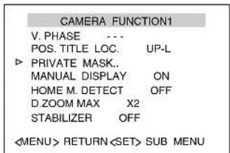
text_image
CAMERA FUNCTION1 V. PHASE POS. TITLE LOC. UP-L PRIVATE MASK.. MANUAL DISPLAY ON HOME M. DETECT OFF D.ZOOM MAX X2 STABILIZER OFF[CAMERA FUNCTION1] screen
■Mask Setting
1 Open the [MASK MODE] screen
- Shift the [PAN/TILT] lever to the left and right and set [MODE] to "ON".
- Press the [SET] button to display the [MASK MODE] screen.

text_image
PRIVATE MASK MODE.. ON BRIGHT 4[PRIVATE MASK] screen
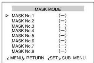
- When "MODE" is set to "OFF", Mask No. 1 to No. 8 will be hidden.
2Select mask number
- Move the cursor on the [MASK MODE] screen to the numbers (Mask No. 1 to No. 8) for private masking, and press the [SET] button.
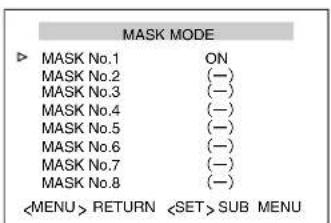
●The [MASK EDIT] screen is displayed. (A frame appears at the mask area)

text_image
MASK EDIT No1[MASK EDIT] screen
Memo :
- If the value is set to "OFF", you will not be able to enter the [MASK EDIT] screen.
- "OUT OF TILT RANGE" will be displayed and Mask setting is unavailable when the tilt position is 40^ and above from the horizontal direction.
- When [MODE] item is set to "OFF", "---" will be displayed and settings is disabled.
- Mask No. 1 to No. 8 are all displayed as (−) at factory default.
- When an edited mask number is selected, the [MASK EDIT] screen will move to the position that has been set.
4Set mask area
| ●[PAN/TILT] lever (up/down/left/right) | Edits the mask positionMemo: ____●When Tilt has stopped at the horizontal edge, Mask can be set horizontally above with the Increased Tilt operation.____ |
| ●[TELE] button●[WIDE] button | Adjusts the size of the mask in the vertical direction |
| ●[NEAR] button●[FAR] button | Adjusts the size of the mask in the horizontal direction |
5Press the [MENU] button
- Save the mask settings and return to the top menu screen ([MASK MODE] screen).
6 Repeat steps 1 to 4
7Press the [MENU] button
Level Setting
1 Select [BRIGHT] at the [PRIVATE MASK] screen
- Move the cursor (▷) to the [BRIGHT] item, shift the [PAN/TILT] lever to the left and right and set the "BRIGHT" (mask color).
●The setting value is 0 (black) to 10 (white).
![JVC TK-C685WPE - Select [BRIGHT] at the [PRIVATE MASK] screen - 1](/content/2026/06/1199146/images/942238dd7fb3e251bca99cca57ed5396bafc310e70d1118c4f86e9a2c5a84b49.jpg)
text_image
PRIVATE MASK MODE ON BRIGHT 4[PRIVATE MASK] screen
Memo :
- To avoid accidental view of masked out area, always check after setting, and if necessary enlarge mask area according to step 4 [Set mask area].
- When Mask is set at the [MASK EDIT] screen, the setting value of the [PRIVATE MASK] screen becomes "ON".
●After Mask settings are complete, individual ON/OFF settings can be made for Mask No. 1 to No. 8.
●The private mask function will not function during initialization after power is switched on. - “OUT OF TILT RANGE” will be displayed and Mask setting is unavailable when the tilt position is 40^ and above from the horizontal direction.
- When adjusting the mask position, release the [PAN/TILT] lever after the tilt angle has reached the horizontal limit, followed by lowering the lever again to move only the private mask upwards. Using this operation enables you to specify a private mask that is beyond the upper limit of the tilt angle.
Home Motion Detect (Alarm) Setting
When the camera is at the home position, the Motion Detect function will activate when there is a movement in the images.
This item sets the locations (non-detection areas) where movement will not be detected.

text_image
[MENU] button [SET] button JVC Numeric keypad [CAMERA] button [PAN/TILT] Lever [ENTER] button [TELE] button [WIDE] button■Preparation
1 Select a camera (RM-P2580 Instruction Manual) [CAMERA] button → Numeric keypad (camera number) → [ENTER] button
●Images from the selected camera are output.
2 Display the [MENU] screen (Page 34)
●The [MENU] screen is displayed.
3Select the [CAMERA FUNCTION1] screen
- Shift up and down the [PAN/TILT] lever, move the cursor (▷) to the [CAMERA FUNCTION1] item and press the [SET] button.
●The [CAMERA FUNCTION1] screen is displayed.
4Open the [HOME M.Detect (ALARM)] screen
- Move the cursor (▷) to the [HOME M.Detect] item, shift the [PAN/TILT] lever to the left and right and select [ALARM].
- Press the [SET] button to display the [HOME M.Detect (ALARM)] screen.
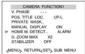
text_image
CAMERA FUNCTION1 V. PHASE .... POS. TITLE LOC. UP-L PRIVATE MASK.. MANUAL DISPLAY ON HOME M. DETECT.. ALARM D. ZOOM MAX X2 STABILIZER OFF[CAMERA FUNCTION1] screen

text_image
HOME M.Detect(ALARM) LEVEL NORMAL AREA EDIT.. TIME 5s DEMONSTRATION..[HOME M.Detect (ALARM)] screen
Setting
1 Setting non-detection area
- Select [AREA EDIT..] and press the [SET] button.
●The [MOTION DETECT AREA EDIT] screen is displayed.
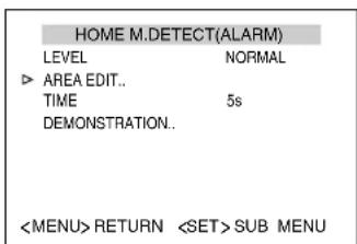
text_image
HOME M.Detect(ALARM) LEVEL NORMAL ► AREA EDIT.. TIME 5s DEMONSTRATION..[HOME M.Detect (ALARM)] screen
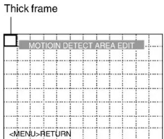
text_image
Thick frame MOTION DETECT AREA EDIT[MOTION DETECT AREA EDIT] screen
Memo :
●The frame is displayed slightly toward the top left from the center of the screen.
- The illustration shows a screen that is divided into 12 × 8 . Only thick frames will be displayed in the actual screen. Lines dividing the screen will not be displayed.
2Select the non-detection area
- Shift the [PAN/TILT] lever (up/down/left/right) and set the non-detection area.
●A thick frame appears around the selected area.
3Set non-detection area
- Press the [SET] button to change the selected area to "white". Setting is complete.
4 Repeat steps 2 and 3
- Set all non-detection areas.
5Press the [MENU] button
- Save the mask settings and return to the top menu screen ([HOME M.Detect (ALARM)] screen).
Memo :
●The position displayed on the screen is an estimation. Be sure to check the actual screen.
Note :
●The Motion Detect feature is not designed to prevent thefts or fire disasters. Our company shall not be liable for any inconveniences or damages that occur.
●The Motion Detect function of this unit detects changes in brightness and movement. As such, depending on changes in the illumination, it may or may not detect movement of objects having the same color as the background color. It may be difficult to detect objects with very slow movement. Check the operating conditions thoroughly beforehand and configure the settings such that there will not be any misoperation or omission of detection.
- This function applies to home position screen when [STABILIZER] item is set to "OFF". When [STABILIZER] is set to "ON", as the screen is enlarged, it will also respond to motion of image which is not shown on the screen. This is the specification of this unit, not a malfunction. (TK-C686E/TK-C686WPE only)
●Cancelling non-detection area
- Select the area (white) that has been set and press the [SET] button.
- The setting is cancelled and the area becomes a “thick frame”.
●Demonstration
1 Select [DEMONSTRATION..] and press the [SET] button
The detected area appears in white.
![JVC TK-C685WPE - Select [DEMONSTRATION..] and press the [SET] button - 1](/content/2026/06/1199146/images/c658e921e4914e3ad98c974e0fe5e5f4d2f876d30c7f5ff9c4d0a71d400470d0.jpg)
text_image
HOME M.Detect(ALARM) LEVEL NORMAL AREA EDIT.. TIME 5s ▶ DEMONSTRATION..[HOME M.Detect (ALARM)] screen
![JVC TK-C685WPE - Select [DEMONSTRATION..] and press the [SET] button - 2](/content/2026/06/1199146/images/0f1fe931eb3295d91ffd09b1e65e6dfd107c0559cfda09fd114834d167bdd441.jpg)
flowchart
graph TD
    A["DEMONSTRATION(ALARM)"] --> B["Detected area (white)"]
    B --> C["<MENU>RETURN"]
[DEMONSTRATION (ALARM)] screen
HOME M.Detect (TRACKING) Setting
This item sets the function to automatically track objects with movement when the camera is at the home position.
Using this feature enables automatic tracking to be performed according to changes in the brightness at the home position.
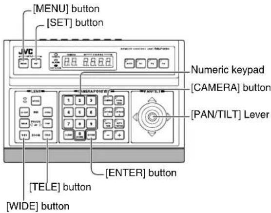
text_image
[MENU] button [SET] button JVC Numeric keypad [CAMERA] button [PAN/TILT] Lever [ENTER] button [TELE] button [WIDE] button■Preparation
1 Select a camera (RM-P2580 Instruction Manual) [CAMERA] button → Numeric keypad (camera number) → [ENTER] button
●Images from the selected camera are output.
2 Display the [MENU] screen (Page 34)
●The [MENU] screen is displayed.
3Select the [CAMERA FUNCTION1] screen
- Shift up and down the [PAN/TILT] lever, move the cursor (▷) to the [CAMERA FUNCTION1] item and press the [SET] button.
●The [CAMERA FUNCTION1] screen is displayed.

text_image
CAMERA FUNCTION1 V. PHASE --- POS. TITLE LOC. UP-L PRIVATE MASK.. MANUAL DISPLAY ON HOME M. DETECT.. TRACKING D. ZOOM MAX X2 STABILIZER OFF[CAMERA FUNCTION1] screen
4Open the [HOME M.Detect (TRACKING)] screen
- Move the cursor (▷) to the [HOME M.Detect] item, shift the [PAN/TILT] lever to the left and right and select [TRACKING].
- Press the [SET] button to display the [HOME M.Detect (TRACKING)] screen.

text_image
HOME M.Detect(TRACKING) ► LEVEL NORMAL RESTART TIME OFF DEMONSTRATION..[HOME M.Detect (TRACKING)] screen
Setting
1 Set [LEVEL]
- Move the cursor (▷) to the [LEVEL] item, shift the [PAN/TILT] lever to the left and right and set the “LEVEL” (motion detection sensitivity).
- The setting value is from -5 (low sensitivity) to 5 (high sensitivity).
![JVC TK-C685WPE - Set [LEVEL] - 1](/content/2026/06/1199146/images/902f1449d4cd49997f846dbb75189d2910426e189bdb400f9afe00b4f1efa4ec.jpg)
text_image
HOME M.Detect(TRACKING) LEVEL 5 RESTART TIME OFF DEMONSTRATION..[HOME M.Detect (TRACKING)] screen
2Set [RESTART TIME]
- Move the cursor (▷) to the [RESTART TIME] item, shift the [PAN/TILT] lever to the left and right and set the duration (RESTART TIME) to return to the home position when there is no movement.
- The camera will return to the home position after the duration set in "RESTART TIME" has passed.
![JVC TK-C685WPE - 2Set [RESTART TIME] - 1](/content/2026/06/1199146/images/9173a10005193afcfd1f9a113b7833ab9210dce08ffcdada77390a48ea61ed25.jpg)
text_image
HOME M.Detect(TRACKING) LEVEL NORMAL RESTART TIME 10s DEMONSTRATION..[HOME M.Detect (TRACKING)] screen
Memo :
- When the [TIME] setting (Page 41) in [AUTO RETURN] item is smaller than the time set in [RESTART TIME], the camera operation will follow the setting in [AUTO RETURN].
●Motion Detect (Tracking) may be difficult under the following conditions. - When multiple moving objects are in the same screen.
- When there is a flickering light source in the screen.
- When the speed of the moving object is fast.
- When the moving object is big or small.
- When the object has no contrast.
●Dark images can be improved with the Increased Electronic Sensitivity function but the response may be slow.
Note :
●The Motion Detect feature is not designed to prevent thefts or fire disasters. Our company shall not be liable for any inconveniences or damages that occur.
●The Motion Detect function of this unit detects changes in brightness and movement. As such, depending on changes in the illumination, it may or may not detect movement of objects having the same color as the background color. It may be difficult to detect objects with very slow movement. Check the operating conditions thoroughly beforehand and configure the settings such that there will not be any misoperation or omission of detection.
- This function applies to home position screen when [STABILIZER] item is set to "OFF". When [STABILIZER] is set to "ON", as the screen is enlarged, it will also respond to motion of image which is not shown on the screen. This is the specification of this unit, not a malfunction. (TK-C686E/TK-C686WPE only)
●Demonstration
1 Select [DEMONSTRATION..] and press the [SET] button
●The detected area is displayed in a pink frame.
![JVC TK-C685WPE - Select [DEMONSTRATION..] and press the [SET] button - 1](/content/2026/06/1199146/images/6b7c518ebf433d5e4643c16bf368a125bb7522b9b6d6eb27da71b186fce48e27.jpg)
text_image
HOME M.Detect(TRACKING) LEVEL NORMAL RESTART TIME OFF ► DEMONSTRATION..[HOME M.Detect (TRACKING)] screen
![JVC TK-C685WPE - Select [DEMONSTRATION..] and press the [SET] button - 2](/content/2026/06/1199146/images/11f16779b002ac457b55d0bec9f6d8fbbff1f3339d2a72b05a9ae6abbc089366.jpg)
flowchart
graph TD
    A["DEMONSTRATION(TRACKING)"] --> B["Detected area (Pink frame)"]
    B --> C["<MENU>RETURN"]
    C --> D["<MENU>RETURN"]
[DEMONSTRATION (TRACKING)] screen
Manual Pan Limit Setting
This feature sets the panning (horizontal) area during manual operation.
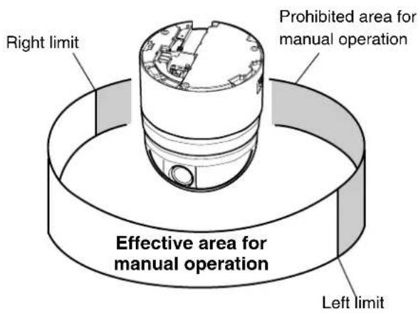
text_image
Right limit Prohibited area for manual operation Effective area for manual operation Left limit
text_image
[MENU] button [SET] button JVC Numeric keypad [CAMERA] button [PAN/TILT] Lever [ENTER] button■Preparation
1 Select a camera (RM-P2580 Instruction Manual)
- [CAMERA] button → Numeric keypad (camera number)
→ [ENTER] button
●Images from the selected camera are output.
2 Display the [MENU] screen (Page 34)
●The [MENU] screen is displayed.
3Select the [CAMERA FUNCTION2] screen
- Shift up and down the [PAN/TILT] lever, move the cursor ( ) to the [CAMERA FUNCTION2] item and press the [SET] button.
●The [CAMERA FUNCTION2] screen is displayed.
![JVC TK-C685WPE - 3Select the [CAMERA FUNCTION2] screen - 1](/content/2026/06/1199146/images/38c166baa7bfc7351f8f9c79dc41191003a630da7b1ed096f48213feef1dcb0d.jpg)
text_image
CAMERA FUNCTION2 FLIP DIGITAL VAR. P / T SPEED ON EASY AF OFF AF FOR IR OFF TILT LIMIT 0° M. PAN LIMIT OFF AUTO RETURN..[CAMERA FUNCTION2] screen
4Open the [M.PAN LIMIT POS.SET] screen
- Move the cursor (▷) to the [M.PAN LIMIT] item, shift the [PAN/TILT] lever to the left and right and select "ON".
5Press the [SET] button
[M.PAN LIMIT POS.SET] (left position) appears.
![JVC TK-C685WPE - 5Press the [SET] button - 1](/content/2026/06/1199146/images/55bc504615a86866c094c538add28dce129ab7bb258a1d5646eaea94b15812e6.jpg)
text_image
M.PAN LIMIT POS. SET [L]POS.SETTING →[M.PAN LIMIT POS.SET] screen (left position)
Setting
1 Set the left limit position
- Use the [PAN/TILT] lever (left/right) to determine the left limit position.
- “[L]POS. SETTING → ” appears at the bottom left of the screen during operation.
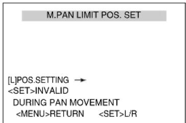
text_image
M.PAN LIMIT POS. SET [L]POS.SETTING →[M.PAN LIMIT POS.SET] screen (left position)
2Press the [SET] button
3Set the right limit position
- Use the [PAN/TILT] lever to determine the right limit position. “← [R]POS. SETTING” appears at the bottom right of the screen during operation.

text_image
M.PAN LIMIT POS. SET[M.PAN LIMIT POS.SET] screen (right position)
4Press the [MENU] button
The configured limit positions are stored and the camera returns to the [CAMERA FUNCTION2] screen.
Memo :
- Tilt, zoom and focus operations are available when this menu is displayed.
- When manual pan limit is already set and this menu is activated, the camera will move to the configured left limit position.
- [SET] is invalid during panning. Press the [SET] button after panning has stopped.
■Basic Operation of Manual Pan Limit
- When manual pan limit is set, panning is only available in the effective area.
●This operation has priority over manual pan limit. When the camera is moved to a prohibited area and manual panning is performed, it operates in the following manner. - Panning can be operated freely even in the prohibited area before the camera enters the effective area.
- Once the camera enters the effective area, the manual pan limit settings take over and pan operation can only be performed in the effective area.
●Operations that have priority over manual pan limit
The following operations are available regardless of the prohibited areas set in manual pan limit.
●Auto Pan
●Auto Trace
- Move Preset Position
- Flip
●Motion Detect (Tracking) Operation
●Settings that have priority over manual pan limit
The following menu settings come together with pan operation but they can be set regardless of the prohibited areas even when manual pan limit has been configured.
●Private Mask Setting
●Auto Pan setting
●Area Display Mode (Title) setting
●Area Display Mode (Direction) setting
Memo :
- When setting Auto Trace and Preset Position and the manual pan limit setting is "ON", panning is unavailable in the prohibited area.
●However, as Auto Trace and Move Preset Position have priority over manual pan limit, set Auto Trace and Preset Position before setting manual pan limit. This will allow both functions to operate in the prohibited area even when manual pan limit is set.
Camera Title Setting
A maximum of 16 characters can be set for the title. It is permanently displayed on the bottom left of the screen. The display position can be set for RM-P2580. (註) Page 38 [POS.TITLE LOC.])

text_image
[MENU] button [SET] button JVC Numeric keypad [CAMERA] button [PAN/TILT] Lever [ENTER] button [TELE] button [WIDE] button■Preparation
1 Select a camera (RM-P2580 Instruction Manual)
- [CAMERA] button → Numeric keypad (camera number)
→ [ENTER] button
●Images from the selected camera are output.
2 Display the [MENU] screen (Page 34)
●The [MENU] screen is displayed.
3Select the [CAMERA TITLE/ALARM] screen
- Shift up and down the [PAN/TILT] lever, move the cursor (▷) to the [CAMERA TITLE/ALARM] item and press the [SET] button.
●The [CAMERA TITLE/ALARM] screen is displayed.
![JVC TK-C685WPE - 3Select the [CAMERA TITLE/ALARM] screen - 1](/content/2026/06/1199146/images/cc186b3688e1d5612ceae173c9b03641a6daf25a9c00d55c5e7bdac2ee38eaaa.jpg)
text_image
MENU LANGUAGE ENGLISH CAMERA FUNCTION1.. CAMERA FUNCTION2.. CAMERA TITLE/ALARM.. CAMERA ALC.. CAMERA VIDEO.. AUTO PAN/PATROL/TRACE.. POS.FUNCTION SET.. FACTORY SETTINGS..[MENU] screen
Setting
1 Check that the cursor (▷) is at [CAM.TITLE EDIT..] and press the [SET] button
●The [CAM.TITLE EDIT] screen is displayed.
●The first character from the character area flashes on and off and is ready for input.
![JVC TK-C685WPE - Check that the cursor (▷) is at [CAM.TITLE EDIT..] and press the [SET] button - 1](/content/2026/06/1199146/images/7cc0d2819bfffb3e0fbc5b5da27a045069d5881e3e20e7adaa2d3df42d71b940.jpg)
text_image
CAMERA TITLE / ALARM ▶ CAM.TITLE EDIT.. AREA DISPLAY OFF ALM. TITLE SIZE DOUBLE ALM. TITLE COLOUR WHITE ALARM TITLE EDIT.. ALARM INPUT.. ALARM OUTPUT..[CAMERA TITLE/ALARM] screen
![JVC TK-C685WPE - Check that the cursor (▷) is at [CAM.TITLE EDIT..] and press the [SET] button - 2](/content/2026/06/1199146/images/8b4d3f0fb4c2dc754ab9b5d6a55886fd77b1637cd765155c8fd8b0dbf51cecf0.jpg)
text_image
Space Character area CAMERA TITLE EDIT [0123456789ABCDEFGHIJKLMNOPQRSTUVWXYZabcdefghijklmnopqrstuvwxyzAOUEIÖUÇNäeiöü aéiöüaéiöüaéiöüçnfič . . . - : / () <> CLR CANCEL [←] [→] INS DEL W T[CAM.TITLE EDIT] screen
2Shift the [PAN/TILT] lever up/down/left/right and select the first character from the character area
●The selected character is displayed flashing on and off.
3Press the [SET] button
●The first character of the title is confirmed and the second character is ready for input.
Memo :
- Press the [WIDE] button to move the cursor position of the title input area to the left. Press the [TELE] button to move it to the right. This is used to modify the configured title.
4 Repeat steps 2 and 3
●Enter the entire camera title.
5Press the [MENU] button
●The new camera title is saved and the top menu screen is displayed.
- To set multiple camera titles, repeat steps from Preparation to Setting.
Area Display Mode Setting (Title)
This function divides the 360^ panning (horizontal rotation) area into 16 areas and displays the area title on the screen when the camera is rotated manually.
A maximum of 16 characters can be set for each area.
Display On/Off (Page 42 [AREA DISPLAY])

text_image
Area 2 Area 1 Area 16 Area 15 Home position
text_image
[MENU] button [SET] button JVC Numeric keypad [CAMERA] button [PAN/TILT] Lever [WIDE], [TELE] button [NEAR], [FAR] button [ENTER] button■Preparation
1 Select a camera (RM-P2580 Instruction Manual)
- [CAMERA] button → Numeric keypad (camera number)
→ [ENTER] button
●Images from the selected camera are output.
2 Display the [MENU] screen (Page 34)
●The [MENU] screen is displayed.
3Select the [CAMERA TITLE/ALARM] screen
- Shift up and down the [PAN/TILT] lever, move the cursor (▷) to the [CAMERA TITLE/ALARM] item and press the [SET] button.
●The [CAMERA TITLE/ALARM] screen is displayed.

text_image
MENU LANGUAGE ENGLISH CAMERA FUNCTION1.. CAMERA FUNCTION2.. ▶ CAMERA TITLE/ALARM.. CAMERA ALC.. CAMERA VIDEO.. AUTO PAN/PATROL/TRACE.. POS.FUNCTION SET.. FACTORY SETTINGS..[MENU] screen
Setting
1 Move the cursor (▷) to [AREA DISPLAY], shift the [PAN/TILT] lever to the left and right to select "TITLE", and press the [SET] button
●The [AREA TITLE EDET AREA1] screen is displayed. (The home position corresponds to area No. 1)
●The first character from the character area flashes on and off and is ready for input.
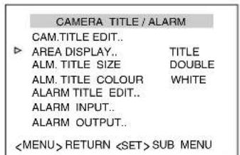
text_image
CAMERA TITLE / ALARM CAM.TITLE EDIT.. AREA DISPLAY.. TITLE ALM. TITLE SIZE DOUBLE ALM. TITLE COLOUR WHITE ALARM TITLE EDIT.. ALARM INPUT.. ALARM OUTPUT..[CAMERA TITLE/ALARM] screen
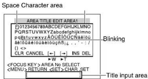
text_image
Space Character area AREA TITLE EDIT AREA1 [0123456789ABCDEFGHIJKLMNOPQRSTUVWXYZabcdefghijklmnopqrstuvwxyzÄÖÜEİÖÜÇNäöü pqrstuvwxyzÄÖÜEİÖÜÇNäöü äeïõuäeïõuäeïõüçhβi...-/- () <> CLR CANCEL [←] [→] INS DEL W T[AREA TITLE EDET AREA1] screen
2Shift the [PAN/TILT] lever up/down/left/right and select the first character from the character area
●The selected character is displayed flashing on and off.
3Press the [SET] button
●The first character of the title is confirmed and the second character is ready for input.
Memo :
- Press the [WIDE] button to move the cursor position of the title input area to the left. Press the [TELE] button to move it to the right. This is used to modify the configured title.
4Press the [FAR] button
●The camera moves to the next area and the [AREA TITLE EDET AREA2] screen appears.
- Press the [NEAR] button to return to the previous area. The [AREA TITLE EDET AREA1] screen appears.
5 Repeat steps 2 to 4
- Enter the entire area title.
6Press the [MENU] button
●The new area title is saved and the top menu screen is displayed.
Area Display Mode Setting (Direction)
When the basic axis direction N (north) is set, this function divides the 360° panning (horizontal rotation) area into 8 areas and displays N, NE, E, SE, S, SW, W, NW respectively for each area when the camera is panned (rotated horizontally) manually.
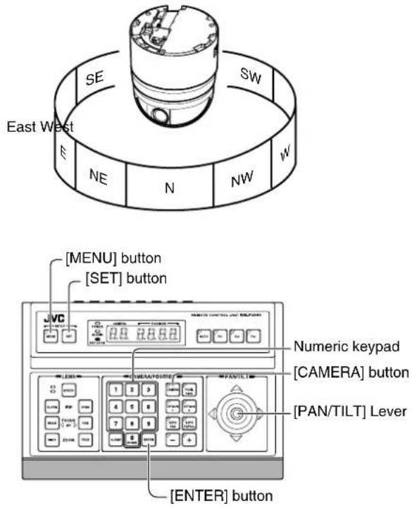
text_image
East West SE SW E NE N NW W [MENU] button [SET] button JVC Numeric keypad [CAMERA] button [PAN/TILT] Lever [ENTER] button■Preparation
1 Select a camera (RM-P2580 Instruction Manual)
- [CAMERA] button → Numeric keypad (camera number)
→ [ENTER] button
●Images from the selected camera are output.
2 Display the [MENU] screen (Page 34)
●The [MENU] screen is displayed.
3Select the [CAMERA TITLE/ALARM] screen
- Shift up and down the [PAN/TILT] lever, move the cursor (▷) to the [CAMERA TITLE/ALARM] item and press the [SET] button.
●The [CAMERA TITLE/ALARM] screen is displayed.
![JVC TK-C685WPE - 3Select the [CAMERA TITLE/ALARM] screen - 1](/content/2026/06/1199146/images/af80d25e4b6bafa6a465494307d6770a9fbe09fd0481f24b589164d9b879c2b4.jpg)
text_image
MENU LANGUAGE ENGLISH CAMERA FUNCTION1.. CAMERA FUNCTION2.. ▶ CAMERA TITLE/ALARM.. CAMERA ALC.. CAMERA VIDEO.. AUTO PAN/PATROL/TRACE.. POS.FUNCTION SET.. FACTORY SETTINGS..[MENU] screen
Setting
1 Move the cursor (▷) to [AREA DISPLAY], shift the [PAN/TILT] lever to the left and right to select "DIR", and press the [SET] button
●The [DIRECTION STANDART AXIS] screen is displayed.
![JVC TK-C685WPE - Move the cursor (▷) to [AREA DISPLAY], shift the [PAN/TILT] lever to the left and right to select "DIR", and press the [SET] button - 1](/content/2026/06/1199146/images/bc5edc7cac2afe4d419ca3f2f7f85cfd3990cc445a02e77a33338024b854c7fb.jpg)
text_image
CAMERA TITLE / ALARM CAM.TITLE EDIT.. AREA DISPLAY.. DIR ALM. TITLE SIZE DOUBLE ALM. TITLE COLOUR WHITE ALARM TITLE EDIT.. ALARM INPUT.. ALARM OUTPUT..![JVC TK-C685WPE - Move the cursor (▷) to [AREA DISPLAY], shift the [PAN/TILT] lever to the left and right to select "DIR", and press the [SET] button - 2](/content/2026/06/1199146/images/a500fd69f42c00aed984e178550870fd4c96d90b125a1ad2489abacd206634e8.jpg)
text_image
DIRECTION STANDARD AXIS SET UP STANDARD AXIS(N)[DIIRECTION STANDART AXIS] screen
2Shift the [PAN/TILT] lever to the left and right and set the basic axis direction (N)
3Press the [MENU] button
●The directional axis start position is set and the direction is displayed on the top left of the screen.
●The direction is displayed respectively as N (north), NE (northeast), E (east), SE (southeast), S (south), SW (southwest), W (west) and NW (northwest).
Memo :
- Tilt, zoom and focus operations are available when this menu is displayed.
- When the directional axis start position is already set and this menu is activated, the camera will move to the configured directional axis start position.
Remote Control Alarm Title Setting
This item sets the title to be displayed during alarm input. Up to 10 titles (remote control alarm title No. 1 to No. 10) and 12 characters for each title can be set.
Memo :
●The following setting in RM-P2580 is required to display the alarm title set in this item.
- Set the [ALARM TEXT] of [TERMINAL] in the [DATA I/O] screen to [EDIT1 to EDIT10].
●Refer to the RM-P2580 Instruction Manual together with this manual.
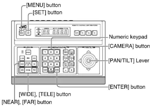
text_image
[MENU] button [SET] button JVC 2.6 0.0 0.0 Numeric keypad [CAMERA] button [PAN/TILT] Lever [ENTER] button [WIDE], [TELE] button [NEAR], [FAR] button■Preparation
1 Select a camera (RM-P2580 Instruction Manual)
- [CAMERA] button → Numeric keypad (camera number)
→ [ENTER] button
●Images from the selected camera are output.
2 Display the [MENU] screen (Page 34)
●The [MENU] screen is displayed.
3Select the [CAMERA TITLE/ALARM] screen
- Shift up and down the [PAN/TILT] lever, move the cursor (▷) to the [CAMERA TITLE/ALARM] item and press the [SET] button.
●The [CAMERA TITLE/ALARM] screen is displayed.
![JVC TK-C685WPE - 3Select the [CAMERA TITLE/ALARM] screen - 1](/content/2026/06/1199146/images/e44ab64df3de3ab4f737e6512418169d003335157a32528012892234fed0fa8a.jpg)
text_image
MENU LANGUAGE ENGLISH CAMERA FUNCTION1.. CAMERA FUNCTION2.. ▶ CAMERA TITLE/ALARM.. CAMERA ALC.. CAMERA VIDEO.. AUTO PAN/PATROL/TRACE.. POS.FUNCTION SET.. FACTORY SETTINGS..[MENU] screen
Setting
1 Move cursor (▷) to [ALARM TITLE EDIT..] and press the [SET] button
●The [ALARM TITLE EDIT No.1] screen is displayed.
●The first character from the character area flashes on and off and is ready for input.
![JVC TK-C685WPE - Move cursor (▷) to [ALARM TITLE EDIT..] and press the [SET] button - 1](/content/2026/06/1199146/images/1d0a2e732a883019b01858eba712a8e1a26e42d50b2a95365136b8f8eb45c411.jpg)
text_image
CAMERA TITLE / ALARM CAM.TITLE EDIT.. AREA DISPLAY OFF ALM. TITLE SIZE DOUBLE ALM. TITLE COLOUR WHITE ► ALARM TITLE EDIT.. ALARM INPUT.. ALARM OUTPUT..[CAMERA TITLE/ALARM] screen
![JVC TK-C685WPE - Move cursor (▷) to [ALARM TITLE EDIT..] and press the [SET] button - 2](/content/2026/06/1199146/images/6c50ff195c6bf626ebce212871062bb3ee07af7aff6c81bcec143ea3af2f8d2f.jpg)
text_image
Space Character area [0123456789ABCDEFGHIJKLMNOPQRSTUVWXYZabcdefghijklmnopqrstuvwxyzÄÖÜEİÖUCNäeöü äéiöüaéiöüaéiöüçnβi¿...-/- ( ) <> CLR CANCEL [←] [→] INS DEL W T2Shift the [PAN/TILT] lever up/down/left/right and select the first character from the character area
●The selected character is displayed flashing on and off.
3Press the [SET] button
●The first character of the title is confirmed and the second character is ready for input.
Memo :
- Press the [WIDE] button to move the cursor position of the title input area to the left. Press the [TELE] button to move it to the right. This is used to modify the configured title.
4Press the [FAR] button
●The next alarm input [ALARM TITLE EDIT No.2] screen appears.
- Press the [NEAR] button to return to the previous alarm input screen.
5 Repeat steps 2 to 4
- Enter the titles for all the alarm input screens ([ALARM TITLE EDIT No.1 to No.10]).
6Press the [MENU] button
- The new remote control alarm title is saved and the top menu screen is displayed.
Auto Pan setting
This item sets the auto pan operation. Auto pan refers to the following operations.
- Slow movement between two preset points (you can set any two points that are connected horizontally, vertically, or diagonally)
●Clockwise rotation in the horizontal direction from the preset point
●Anti-clockwise rotation in the horizontal direction from the preset point
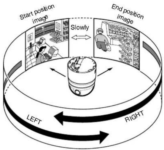
flowchart
graph TD
    A["Start position image"] --> B["Right"]
    B --> C["Left"]
    C --> D["Slowly"]
    D --> E["End position image"]
    E --> F["Right"]
    F --> G["Left"]
    G --> H["Slowly"]
    H --> I["End position image"]

natural_image
Diagram of a satellite with surrounding camera and distance markers, set against an architectural background (no text or symbols)
text_image
[MENU] button [SET] button JVC Numeric keypad [CAMERA] button [PAN/TILT] Lever [ENTER] button [FOCUS (NEAR) (FAR)] button [ZOOM (WIDE) (TELE)] button■Preparation
1 Select a camera (RM-P2580 Instruction Manual)
- [CAMERA] button → Numeric keypad (camera number)
→ [ENTER] button
●Images from the selected camera are output.
2 Display the [MENU] screen (Page 34)
●The [MENU] screen is displayed.
3Display the [AUTO PAN/PATROL/TRACE] screen
- Shift up and down the [PAN/TILT] lever, move the cursor ( ) to the [AUTO PAN/PATROL/TRACE] item and press the [SET] button.
●The [AUTO PAN/PATROL/TRACE] screen is displayed.

text_image
MENU LANGUAGE ENGLISH CAMERA FUNCTION1.. CAMERA FUNCTION2.. CAMERA TITLE/ALARM.. CAMERA ALC.. CAMERA VIDEO.. AUTO PAN/PATROL/TRACE.. POS.FUNCTION SET.. FACTORY SETTINGS..[MENU] screen
Setting
1 Select [AUTO PAN SET..] and press the [SET] button
- Check that the cursor is at [AUTO PAN SET..] and press the [SET] button
●The [AUTO PAN SET] screen is displayed.
![JVC TK-C685WPE - Select [AUTO PAN SET..] and press the [SET] button - 1](/content/2026/06/1199146/images/1c2804eb66e31666a3205867196210f5593174ae39f517d66d695473296efe1d.jpg)
text_image
AUTO PAN/PATROL/TRACE ▶ AUTO PAN SET.. AUTO PATROL SET.. AUTO TRACE SET.. A. PAN/TRACE VIDEO.. RM. A. PAN KEY A. PAN RM. A. PATROL KEY A. PATROL[AUTO PAN/PATROL/TRACE] screen
![JVC TK-C685WPE - Select [AUTO PAN SET..] and press the [SET] button - 2](/content/2026/06/1199146/images/2a29aaa22160873496e7a1b0446388a94c6a9506bac3bab3f623f6c801e4051f.jpg)
text_image
AUTO PAN SET ▶ AUTO PAN MODE RETURN AUTO PAN SPEED NORMAL A PAN POS SET..[AUTO PAN SET] screen
2Set [AUTO PAN MODE] and [AUTO PAN SPEED]
- Set Auto Pan operation in the [AUTO PAN MODE] item. [Setting value: RETURN, RIGHT, LEFT]
- Set Auto Pan rotation speed in the [AUTO PAN SPEED] item.
[Setting value: LOW, NORMAL, HIGH]
3 Move the cursor (▷) to the [A.PAN POS.SET..] item and press the Set button (only during Shuttle)
The Auto Pan Position Setting screen appears.
4Align the field angle of the start position (only during Shuttle)
- Use the [PAN/TILT] lever and [FOCUS (NEAR) (FAR)], [ZOOM (WIDE) (TELE)] buttons to align the screen.
●Lens operations such as focus cannot be performed at the End Position Setting screen. - “[START]POS.SET →” appears at the bottom left of the setting screen.

text_image
AUTO PAN POSITION SET [START] POS. SET→[AUTO PAN POSITION SET] screen (Start position)
5 Press the [SET] button (only during "RETURN")
The start position switches to the end position.
![JVC TK-C685WPE - Press the [SET] button (only during "RETURN") - 1](/content/2026/06/1199146/images/8183cb8f64b08547792ef952b7286c11bf10c7b7fc35283553c4135f0ee9be78.jpg)
text_image
AUTO PAN POSITION SET ← [END] POS.SET[AUTO PAN POSITION SET] screen (End position)
6Set the end position (only during Shuttle)
- Set the return position with the [PAN/TILT] lever.
- “← [END]POS.SET” appears at the bottom right of the setting screen.
- Vertical direction and lens operations such as focus and zoom cannot be performed at the End Position Setting screen.
7Press the [MENU] button
- The new auto pan position is saved and the top menu ([AUTO PAN SET] screen) is displayed.
Memo :
●Focus operation cannot be performed at the end position.
- The correct setting data is not written if the [SET] or [MENU] button is pressed when the camera is moving. Always check that the camera has stopped before pressing the buttons.
●The Manual Pan Limit mode is OFF temporarily when this menu is displayed. After the menu is completed, you can set Manual Pan Limit without affecting the movement.
- To operate Auto Pan in the camera, press the [AUTO PAN] button of RM-P2580.
- For details, refer to the RM-P2580 Instruction Manual.
Auto Patrol Setting
This item sets the Auto Patrol function where the camera moves to multiple positions in order.
Three modes (mode 1 to 3) and up to 100 patrols (1 to 32) can be set for each mode. (It is convenient if you set the mode in day or time slots. For example, mode 1 is night, mode 2 is day and so on.)
Memo :
- Register the positions before setting. For details on registering positions, refer to the RM-P2580 Instruction Manual.
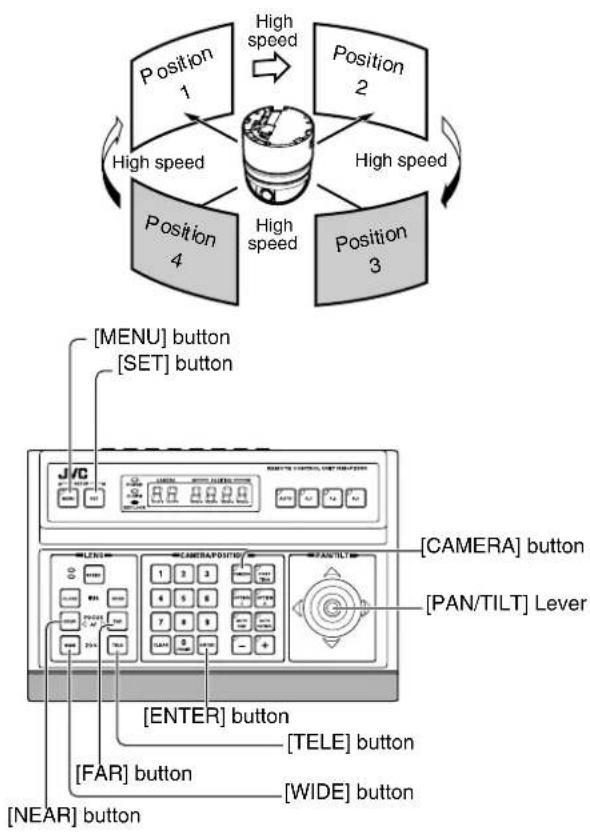
flowchart
graph TD
    A["Position 1"] -->|High speed| B["Central Device"]
    C["Position 2"] -->|High speed| B
    D["Position 3"] -->|High speed| B
    E["Position 4"] -->|High speed| B
    F["ENCER"] --> G["CAMERA"] button
    H["LENG"] --> I["PAN/TILT"] Lever
    J["ENTER"] --> K["TELE"] button
    L["FAR"] --> M["WIDE"] button
    N["NEAR"] --> O["CameraPOLD"] button
    P["SET"] button --> Q["CameraPOLD"]
    R["MENU"] button --> S["CameraPOLD"]
■Preparation
1 Select a camera (RM-P2580 Instruction Manual)
- [CAMERA] button → Numeric keypad (camera number)
→ [ENTER] button
●Images from the selected camera are output.
2 Display the [MENU] screen (Page 34)
3Shift up and down the [PAN/TILT] lever, move the cursor (▷) to the [AUTO PAN/PATROL/TRACE] item and press the [SET] button
The [AUTO PAN/PATROL/TRACE] screen is displayed.
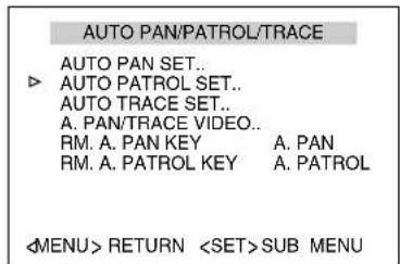
text_image
AUTO PAN/PATROL/TRACE AUTO PAN SET.. AUTO PATROL SET.. AUTO TRACE SET.. A. PAN/TRACE VIDEO.. RM. A. PAN KEY A. PAN RM. A. PATROL KEY A. PATROL[AUTO PAN/PATROL/TRACE] screen
4 Move the cursor (▷) to the [AUTO PATROL SET..] item and press the [SET] button
The [AUTO PATROL SET MODE1] screen is displayed.
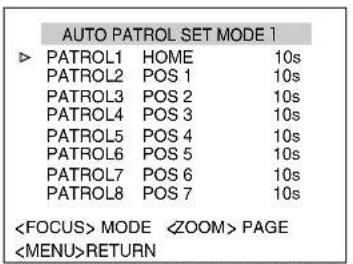
text_image
AUTO PATROL SET MODE 1 PATROL1 HOME 10s PATROL2 POS 1 10s PATROL3 POS 2 10s PATROL4 POS 3 10s PATROL5 POS 4 10s PATROL6 POS 5 10s PATROL7 POS 6 10s PATROL8 POS 7 10s[AUTO PATROL SET MODE1] screen (Patrol 1 to 8 display example)
Setting
1 Shift up and down the [PAN/TILT] lever and move the cursor (▷) to a patrol number you wish to set
- To display the next setting page (Patrol 9 to 16), press the [TELE] button.
●To display the previous page, press the [WIDE] button.
![JVC TK-C685WPE - Shift up and down the [PAN/TILT] lever and move the cursor (▷) to a patrol number you wish to set - 1](/content/2026/06/1199146/images/9483b920d8b38dd9d01636136797871e9a463eee2fa93aea9599a253948faa72.jpg)
text_image
AUTO PATROL SET MODE1 PATROL9 POS 8 10s PATROL10 POS 9 10s PATROL11 POS 10 10s PATROL12 POS 11 10s PATROL13 POS 12 10s PATROL14 POS 13 10s PATROL15 POS 14 10s PATROL16 POS 15 10s[AUTO PATROL SET MODE1] screen
(Patrol 9 to 16 display example)
2Set the position
[POSITION] button → Numeric keypad (position number) → [ENTER] button
●Patrol 1 is set as Home and Patrol 2 to 100 are set as Positions 1 to 99 respectively for the default values.
3Set the time
- Shift the [PAN/TILT] lever to the left and right and set the time. (seconds, minutes) [Setting value: SKIP, 10s, 20s, 30s, 45s, 1min, 2min]
Memo :
- If Skip is selected, Auto Patrol will be skipped and not be selected.
- Default settings are all set to "10s".
4 Repeat steps 1 to 3
- Set the positions and time for all patrol numbers.
5Change the mode
- Use the [FAR] and [NEAR] button to change the mode.
●After the mode is changed, repeat steps 1 to 4.
6Press the [MENU] button
●This returns to the top menu.
●The new auto pan position is saved and the top menu screen is displayed.
To operate Auto Patrol:
- To operate Auto Patrol in the camera, press the [AUTO PATROL] button of RM-P2580.
- To change the Auto Patrol mode after setting, display the Auto Patrol Mode screen and use the [FAR] and [NEAR] buttons.
Auto Trace Setting
This item sets the Auto Trace function (approx. 30 seconds) that reproduces manual camera settings.
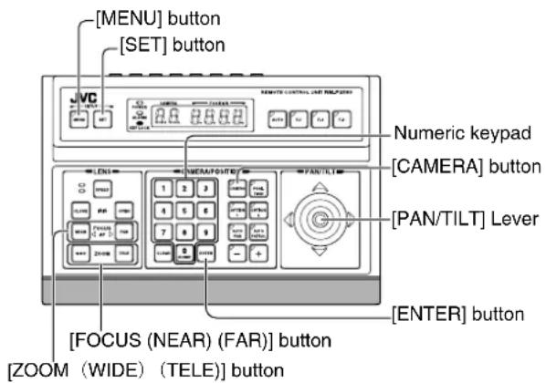
text_image
[MENU] button [SET] button JVC 2.0 2.0 2.0 Numeric keypad [CAMERA] button [PAN/TILT] Lever [FOCUS (NEAR) (FAR)] button [ZOOM (WIDE) (TELE)] button [ENTER] button■Preparation
1 Select a camera (RM-P2580 Instruction Manual)
- [CAMERA] button → Numeric keypad (camera number)
→ [ENTER] button
●Images from the selected camera are output.
2 Display the [MENU] screen (Page 34)
●The [MENU] screen is displayed.
3Display the [AUTO PAN/PATROL/TRACE] screen
- Shift up and down the [PAN/TILT] lever, move the cursor (▷) to the [AUTO PAN/PATROL/TRACE] item and press the [SET] button.
●The [AUTO PAN/PATROL/TRACE] screen is displayed.
![JVC TK-C685WPE - 3Display the [AUTO PAN/PATROL/TRACE] screen - 1](/content/2026/06/1199146/images/bd62bc55e76b3b748f15abcccbebac56f969a2e94e62c6a964ba7ee7e645e17c.jpg)
text_image
MENU LANGUAGE ENGLISH CAMERA FUNCTION1.. CAMERA FUNCTION2.. CAMERA TITLE/ALARM.. CAMERA ALC.. CAMERA VIDEO.. AUTO PAN/PATROL/TRACE.. POS.FUNCTION SET.. FACTORY SETTINGS..[MENU] screen
![JVC TK-C685WPE - 3Display the [AUTO PAN/PATROL/TRACE] screen - 2](/content/2026/06/1199146/images/b8e9ceb9bc63f281b2ef3344213b2b2b2dbc51d943a6544bd4c3d18b94bbe629.jpg)
text_image
AUTO PAN/PATROL/TRACE AUTO PAN SET.. AUTO PATROL SET.. ▶ AUTO TRACE SET.. A. PAN/TRACE VIDEO.. RM. A. PAN KEY A. PAN RM. A. PATROL KEY A. PATROL[AUTO PAN/PATROL/TRACE]screen
4 Move the cursor (▷) to the [AUTO TRACE..] item and press the [SET] button
●The Auto Trace Setting screen appears.
![JVC TK-C685WPE - Move the cursor (▷) to the [AUTO TRACE..] item and press the [SET] button - 1](/content/2026/06/1199146/images/8abaeb7d181c23d45b2dda3911082c8a589a783bc5c3e5c2bdcd3242537be5b1.jpg)
text_image
AUTO TRACE SET SET START POSITION[AUTO TRACE SET] screen
Setting
1 Set start position
- Use the [PAN/TILT] lever and [FOCUS (NEAR) (FAR)], [ZOOM (WIDE) (TELE)] buttons to set the start position of the Auto Trace function.
2Press the [SET] button (Start recording)
- The camera enters the Auto Trace recording state. Use the [PAN/TILT] lever and [FOCUS (NEAR) (FAR)], [ZOOM (WIDE) (TELE)] buttons to operate the camera.
- The Auto Trace function stores recording for maximum 30 seconds. During recording, “LEARNING REMAINDER T:**s” is displayed on the screen. After 30 seconds, the recording ends automatically.
●To end recording within 30 seconds, follow step 3.
●The recording time may be shortened depending on the operation. (Minimum 10 seconds)
AUTO TRACE SET
LEARNING REMAINDER T: * * S