ACM-1232 - Security Camera ACTi - Free user manual and instructions
Find the device manual for free ACM-1232 ACTi in PDF.


| Product Type | MegaPixel IP Outdoor IR Bullet Camera |
| Model | ACM-1232 (ACM-1230 series) |
| Image Sensor | 1/3" Progressive Scan CMOS (assumed) |
| Resolution | Up to 1.3 MP (1280x960) (based on series typical) |
| Lens | Varifocal, manual focus/zoom (adjustable) |
| IR Range | Up to 30 meters (estimated) |
| Video Compression | H.264, MJPEG (standard) |
| Ethernet Port | RJ45, 10/100 Mbps, NWAY auto-detection |
| Power Input | DC 12V or AC 24V (terminal block) or PoE (IEEE 802.3af) |
| Power Consumption | Approximately 6W (estimated) |
| Audio | 1-channel audio input, 1-channel audio output (terminal block) |
| Reset Button | Yes, factory reset via button |
| Default IP Address | 192.168.0.100 |
| Default Login | Username: Admin, Password: 123456 |
| Video Output | BNC connector for analog monitor |
| Indoor/Outdoor | Outdoor, weatherproof (IP66 rated, assumed) |
| Operating Temperature | -20°C to 50°C (estimated) |
| Dimensions (approx.) | 100 x 70 x 200 mm (estimated) |
| Weight (approx.) | 0.6 kg (estimated) |
| Warranty | Standard manufacturer warranty (details in card) |
Frequently Asked Questions - ACM-1232 ACTi
User questions about ACM-1232 ACTi
0 question about this device. Answer the ones you know or ask your own.
Ask a new question about this device
Download the instructions for your Security Camera in PDF format for free! Find your manual ACM-1232 - ACTi and take your electronic device back in hand. On this page are published all the documents necessary for the use of your device. ACM-1232 by ACTi.
USER MANUAL ACM-1232 ACTi
natural_image
Abstract geometric design with overlapping triangular shapes and a white triangle, no text or symbols present.MegaPixel IP Outdoor IR Bullet Camera
(with DC 12V / PoE / AC24V)
ACM-1230 series
Ver. 080122
Quick Installation Guide

ACTi
www.acti.com
1
Getting Started
1.1 PACKAGE CONTENTS
ACM-1230 series (DC12V / PoE / AC24V)
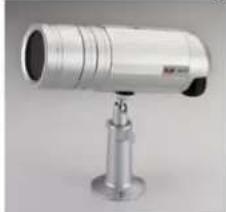
natural_image
Exterior view of a metallic surveillance camera mounted on a stand (no visible text or symbols)Power Adaptor (Option)
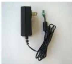
natural_image
Electric power adapter with attached cable and connector (no visible text or symbols)Product CD
natural_image
Circular optical disc with a central lens and CD, no visible text or symbols on the disc itself.Terminal Block for Power
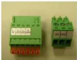
natural_image
Two green electrical connectors with red and green labels, no visible text or symbols on the connectors themselves.Warranty Card
1.2 PHYSICAL DESCRIPTION
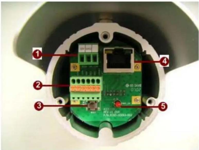
1. Power Input
If your power input is DC12V. Please follow the description on the connector to connect to power.
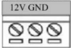
| PIN | NAME | DESCRIPTION |
| 1 12V | DC Power Input | |
| 2 | GND | Ground Pin |
If your power input is AC24V. Please follow the description on the connector to connect to power.
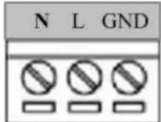
| PIN | NAME | DESCRIPTION |
| 1 | N | AC Power Input |
| 2 | L | |
| 3 GND | E-Ground of power |
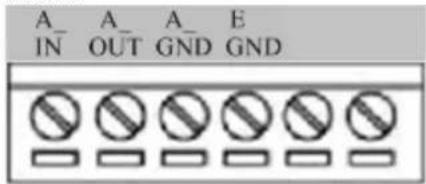
2. Audio Input / Output
The IP device supports audio input and output, with terminal block.
3. Reset Button
Step 1: Switch off IP device by disconnecting the power cable
Step 2: Press and continue to hold the Reset Button. Reconnect the power cable while continuing to hold the reset button.
Step 3: Keep holding the reset button depressed for a while, release the reset button. The unit will start up with factory default settings.
4. Ethernet Port
The IP device connects to the Ethernet via a standard RJ45 connector. Supporting NWAY, this IP device can auto detect the speed of local network segment (10Base-T/100Base-TX Ethernet).
5. Power LED Indicator
The LED indicator lights up one time upon power up. It will lights up again when this IP device is fully booted up.
1.3 BASIC CONNECTIONS
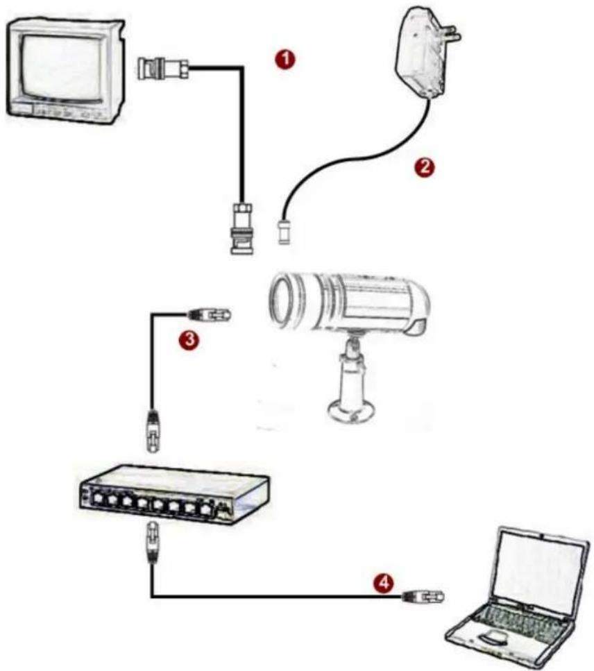
Follow the procedures below to connect the IP device to the respective apparatuses.
flowchart
graph TD
    A["TV Device"] --> B["Switch"]
    B --> C["Printer"]
    C --> D["Laptop"]
    D --> E["Camera"]
    E --> F["Laptop"]
    style A fill:#f9f,stroke:#333
    style B fill:#ccf,stroke:#333
    style C fill:#cfc,stroke:#333
    style D fill:#fcc,stroke:#333
    style E fill:#cff,stroke:#333
    style F fill:#ffc,stroke:#333
- Connect an analog monitor to IP device video out (BNC connector).
- Connect the power adaptor to IP device
- Connect IP device's ethernet port to an Ethernet (RJ45 connectors). If your IP device has PoE built-in, you can regard it as a PD and connect it directly to a PSE device like PoE switch.
- Connect a PC to the Ethernet hub (RJ45 connectors)

NOTE: You may find a support package for help you getting familiar with PoE. Please visit our web site, and get the support document TS-00040.
1.4 Installation Procedure
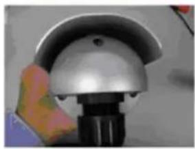
- Remove camera back
natural_image
Close-up of a hand holding a metallic helmet with a black base (no visible text or symbols)
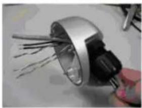
- Connect the cables
natural_image
Close-up of a metallic mechanical component with wires, being handled by a hand (no visible text or symbols)
- I/O connecting
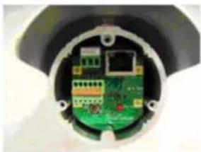
natural_image
Close-up of a green printed circuit board inside a black plastic housing (no visible text or symbols)
- Install camera back
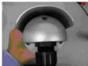
natural_image
Close-up of a hand holding a metallic dome-shaped object with a black base (no visible text or symbols)
- Install the camera onto bracket and remove sunshield
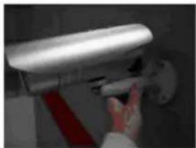
natural_image
Close-up of a hand holding a security camera mounted on a wall, with no visible text or symbols.
- Remove the camera cover
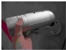
natural_image
Hand holding a cylindrical mechanical component, possibly a tool or device, with no visible text or symbols.
- Adjust focus/zoom
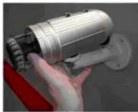
natural_image
Close-up of a hand holding a metallic cylindrical device with a red cable attached (no visible text or symbols)
- Install sunshield and camera cover back
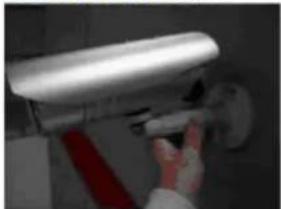
natural_image
Close-up of a hand adjusting a wall-mounted security camera (no visible text or symbols)2
Quick Tour
This section guides you with a quick tour on this IP device.
2.1 Configure this IP Device
2.1.1 Make sure network environment
Default IP of this IP device is 192.168.0.100. Please make sure this IP device and your PC are on the same network segment before running the installation.
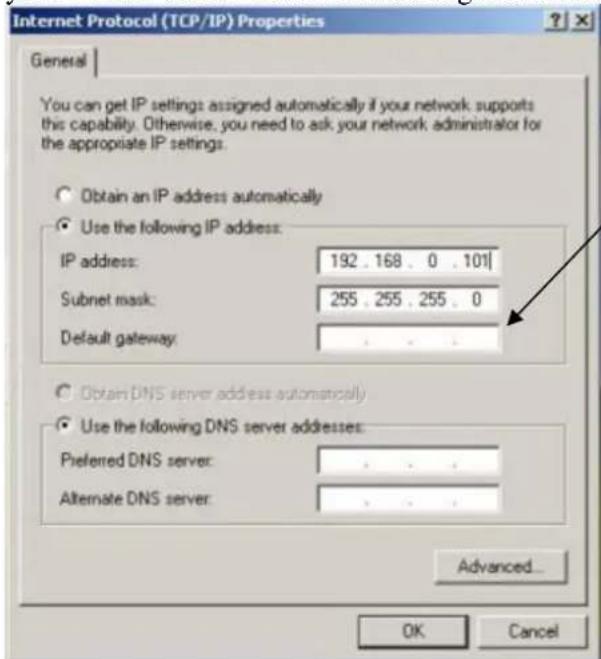
Please set the settings as below.
IP address: 192.168.0.xxx Subnet mask: 255.255.255.0
(NOTE: xxx should be a number from 1 to 254, but 100 is excepted.)
2.1.2 Open Internal Explorer with IP address
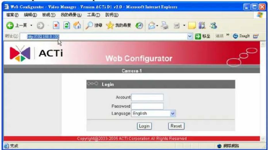

NOTE: If your web browser is earlier than IE6, then download IE6 is recommended.

NOTE: This IP device default IP address is set to 192.168.0.100
2.1.3 Login with default administrator's account & password
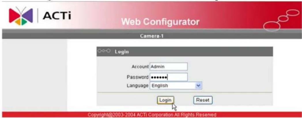

NOTE: Default administrator account is set to Admin, password is set to 123456, and click Login button.
2.1.4 Preview the video
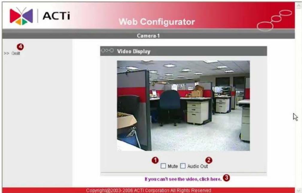
2.1.5 Set the new IP address

ACTi
Web Configurator
Camera-1
Video Display
Host Setting
WAN Setting
Date Setting
Video Setting
Video Adjust
User Account
System Info
Firmware
Factory Default
Save Reboot
Logout
WAN Setting *
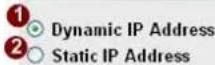
6 ○ PPPoE
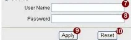
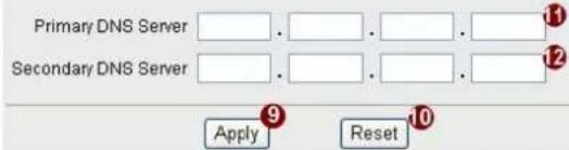
DNS Server Setting
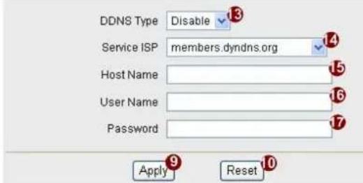
DDNS Server Setting
Copyright@2003-2006 ACTI Corporation All Right Reserved
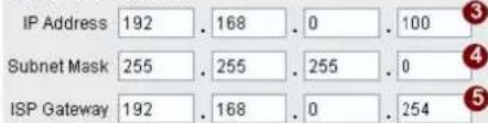
*IP Address : The default IP address is 192.168.0.100.
*Subnet Mask : The default subnet mask is 255.255.255.0
*Click Apply button

NOTE: In your Client PC, please make sure the setting of Network Connections Type is set to Auto Negotiation, since this IP device follows MII standard. Otherwise, you might not see the live image.

IMPORTANT: After the IP address is changed, please record this IP address. There's no way to connect to the IP device if user forgets the new IP address.
2.1.6 Check Default Video Setting
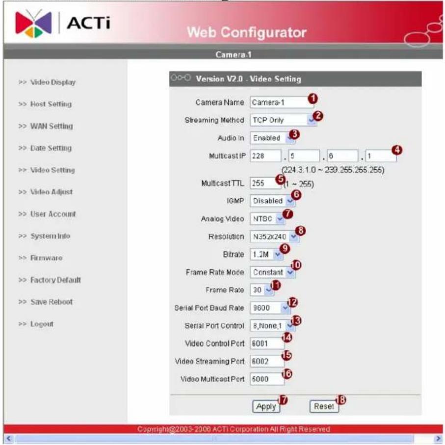

NOTE: Please make sure the TV Input (NTSC / PAL) is meet your requirement, and click Apply button.
2.1.7 Click Save Reboot to restore all settings and please wait about 30 seconds for system reboot.
- MegaPixel IP Outdoor IR Bullet Camera
- Quick Installation Guide
- 1
- Getting Started
- PACKAGE CONTENTS
- PHYSICAL DESCRIPTION
- Power Input
- Audio Input / Output
- Reset Button
- Ethernet Port
- Power LED Indicator
- BASIC CONNECTIONS
- Installation Procedure
- 2
- Quick Tour
- Configure this IP Device
- Make sure network environment
- Open Internal Explorer with IP address
- Login with default administrator's account & password
- Preview the video
- Set the new IP address
- ACTi
- Web Configurator
- Check Default Video Setting
Brand : ACTi
Model : ACM-1232
Category : Security Camera