Q75 - Security Camera ACTi - Free user manual and instructions
Find the device manual for free Q75 ACTi in PDF.


| Product Type | Outdoor Multi-Imager Panoramic Dome Camera |
| Model | Q75 |
| Brand | ACTi |
| Resolution | 20MP (4 x 5MP sensors) |
| Lens | 4 fixed lenses |
| Day/Night | Yes, with Adaptive IR |
| Wide Dynamic Range | Extreme WDR |
| Smart Light Compensation | SLLS |
| Power Supply | PoE (IEEE802.3at Class4) or external DC12~24V/AC24V adapter |
| Ethernet Port | 1 x RJ-45 (10/100/1000 Mbps) |
| Audio Input | 1 x 3.5mm jack (requires amplified microphone) |
| Audio Output | 1 x 3.5mm jack |
| Digital Input | 1 x terminal block (alarm input) |
| Digital Output | 1 x terminal block (alarm output) |
| Memory Card Slot | Yes, for local recording |
| Reset Button | Yes (press 10 seconds for factory reset) |
| Mounting Options | Wall mount, pendant mount, pole mount, corner mount, direct surface |
| Waterproof Rating | Camera body waterproof; cable connections must be waterproofed |
| Operating Environment | Outdoor, avoid extreme temperatures and humidity |
| Dimensions | Approximately 200mm diameter x 150mm height (estimated) |
| Weight | Approximately 2.5 kg (estimated) |
| Compliance | FCC Class A, CE EN 55022 & EN 55024 |
| Cleaning | Disconnect power before cleaning; use dry cloth |
| User-Serviceable Parts | None; refer servicing to qualified personnel |
| Included Accessories | Cable gland, screw pack, rubber ring, wrench, drill template, QIG & warranty card |
Frequently Asked Questions - Q75 ACTi
User questions about Q75 ACTi
0 question about this device. Answer the ones you know or ask your own.
Ask a new question about this device
Download the instructions for your Security Camera in PDF format for free! Find your manual Q75 - ACTi and take your electronic device back in hand. On this page are published all the documents necessary for the use of your device. Q75 by ACTi.
USER MANUAL Q75 ACTi
natural_image
Abstract geometric design with a red square and a gray star-like shape (no text or symbols)Outdoor Multi-Imager Dome Hardware Manual
Q75
2020/08/13
Table of Contents
Precautions 4
Safety Instructions 6
Introduction......7
List of Models....7
Package Contents......8
Physical Description 9
Mounting Options....11
Precautions....11
Before Installation.... 12
Open the Dome Cover 12
Insert the Memory Card (Optional).... 12
Installation Procedures....13
Mounting the Camera with Wall Mount.... 13
Mounting the Camera Directly on the Surface 16
Remove the Mount Kit....16
Mount the Camera 17
Waterproof the Cable Connections.... 19
How to Use the Cable Gland....19
Connect to Network....22
Other Cable Connections....23
How to Connect a Power Adapter (Optional) 24
How to Connect Digital Input / Digital Output Devices.... 25
Connecting DI/DO Devices 25
How to Connect Audio Devices.... 27
How to Attach the RJ-45 Connector.... 28
Accessing the Camera 30
Configure the IP Addresses.... 30
Access the Camera.... 34
Precautions
Read these instructions
You should read all the safety and operating instructions before using this product.
- Do not use the camera in unstable lighting conditions.
- Never use the camera close to gas or oil leak.
- Never face the camera to strong light for long periods of time.
Heed all warnings
You must adhere to all the warnings on the product and in the instruction manual. Failure to follow the safety instructions given may directly endanger people, cause damage to the system or to other equipment.
Servicing
Do not attempt to service this video device yourself as opening or removing covers may expose you to dangerous voltage or other hazards. Refer all servicing to qualified service personnel.
Trademarks
All names used in this manual are probably registered trademarks of respective companies.
Liability
Every reasonable care has been taken during the writing of this manual. Please inform your local office if you find any inaccuracies or omissions. We cannot be held responsible for any typographical or technical errors and reserve the right to make changes to the product and manuals without prior notice.
Federal Communications Commission Statement
This device complies with Part 15 of the FCC Rules. Operation is subject to the following two conditions:
- This device may not cause harmful interference.
- This device must accept any interference received, including interference that may cause undesired operation.
Note: This equipment has been tested and found to comply with the limits for a Class A digital device, pursuant to Part 15 of the FCC Rules. These limits are designed to provide reasonable protection against harmful interference when the equipment is operated in a commercial environment. This equipment generates, uses, and can radiate radio frequency energy, and if it is not installed and used in accordance with the instruction manual, it may cause harmful interference to radio communications. Operation of this equipment in a residential area is likely to cause harmful interference, in which case the user will be required to correct the interference at their own expense.
European Community Compliance Statement

This product has been tested and found to comply with the limits for Class A Information Technology Equipment according to European Standard EN 55022
and EN 55024. In a domestic environment, this product may cause radio interference in which cause the user may be required to take adequate measures.
Safety Instructions
Cleaning
Disconnect this video product from the power supply before cleaning.
Attachments
Do not use attachments or accessories not recommended by the video product manufacturer as they may cause hazards.
Water and Moisture
Install other devices (such as PoE injector, alarm, etc.) that will be used with the camera in a dry place protected from weather.
Servicing
Do not attempt to service this video product yourself. Refer all servicing to qualified service personnel.
Damage Requiring service
Disconnect this video product from the power supply immediately and refer servicing to qualified service personnel under the following conditions:
1) When the power-supply cord or plug is damaged.
2) If liquid has been spilled or objects have fallen into the video product.
3) If the inner parts of the video product have been directly exposed to rain or water.
4) If the video product does not operate normally by following the operating instructions in this manual. Adjust only those controls that are covered by the instruction manual, as an improper adjustment of other controls may result in damage, and will often require extensive work by a qualified technician to restore the video product to its normal operation.
Safety Check
Upon completion of any service or repairs to this video product, ask the service technician to perform safety checks to determine if the video product is in proper operating condition.
Introduction
List of Models
This hardware manual contains the following model:
| Q75 | 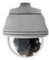 | 20MP Outdoor Multi-Imager Panoramic Dome with D/N, Adaptive IR, Extreme WDR, SLLS, 4 Fixed Lenses, 4 pcs 5MP Sensors |
Package Contents
Check if the following items come with the camera package. If any of them is missing, please contact your local sales agents or the Customer Help Desk (CHD).
| Camera | Cable Gland | Screw Pack |
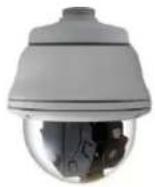 |  |  |
| Rubber Ring | Wrench | Drill Template |
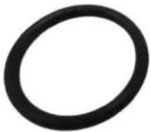 | 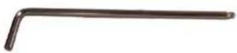 |  |
| QIG& Warranty Card | ||
 | ||
Physical Description
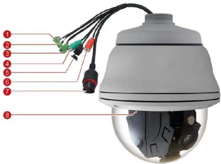
| No. | Item | Description |
| 1 | Digital Output | This connector connects to digital output device, such as alarm, etc. Digital Output (DO) devices are used for applications like motion detection, event triggering, alarm notifications, etc. SeeHow to Connect Digital Input / Digital Output Deviceson page 25 for information. |
| 2 | Digital Input | This connector connects to a digital input device, such as a panic button, etc. Digital Input (DI) devices are used for applications like motion detection, event triggering, alarm notifications, etc. SeeHow to Connect Digital Input / Digital Output Deviceson page 25 for information. |
| 3 | Power Input | This jack connects to the power adapter and power cord to supply power to the camera. SeeHow to Connect a Power Adapteron page 24. |
| 4 | Audio Output | This jack connects to an audio output device, such as a speaker. SeeHow to Connect Audio Deviceson page 27. |
| 5 | Reset Button | The reset button is used to restore the factory default settings of the camera, including the administrator's password.To reset the camera, do the following: Press and hold the reset button for at least 10 seconds. The camera may take a few second to start resetting. |
| 6 | Audio Input | This jack connects to an audio input device, such as a microphone with built-in amplifier. SeeHow to Connect Audio Deviceson page 27.NOTE:Make sure that the connected audio input device has a built-in amplifier. Connecting an ordinary microphone will dwarf sounds and will result in inaudible recording. |
| 7 | Ethernet Port | The Ethernet port connects to a network using a standard Ethernet cable. |
| 8 | Memory Card Slot | Insert a memory card for local recording. SeeInsert the Memory Card(Optional)on page 12. |
Mounting Options
The camera can be directly mounted on the surface by removing the mount kit which is attached at the top of the camera (see Mounting the Camera Directly on the Surface on page 16 for instructions). However, there are also several mounting installation options that you can use, such as pendant mount, wall mount, pole mount, etc. For more information about mounting solutions and accessories, please visit our website (http://www.acti.com/mountingselector).
| Mount Types | Accessories | |
| Pendant Mount | Suitable when mounting the camera on a hard ceiling. | |
| Straight Wall Mount | Suitable when mounting the camera on a straight wall. | |
| Vertical Pole Mount | Suitable when mounting the camera on a vertical pole. | |
| Horizontal Pole Mount | Suitable when mounting the camera on a horizontal pole. | |
| Corner Mount | Suitable when mounting the camera on a corner wall. | |
Precautions
- Do not use the camera in extreme temperature. Air vent is required at high temperature.
- Do not use or store the camera in humid environment. It may cause poor image quality.
- Do not use the camera in unstable lighting conditions. Inconsistent lighting or flickering may cause poor image quality.
- Never use the camera close to gas or oil leak. It may not operate properly.
- Do not disassemble the camera. There is no user serviceable part inside.
- Do not drop the camera or apply force on it. It may cause a malfunction.
- Never face the camera to strong light for long periods of time. It may damage the CMOS sensor.
- External power supply cannot be used with POE simultaneously, or it may damage the camera.
Before Installation
This section describes the procedures that can be done to prepare the camera prior to installation. Note that some may not be applicable to your installation environment; do them as needed.
Open the Dome Cover
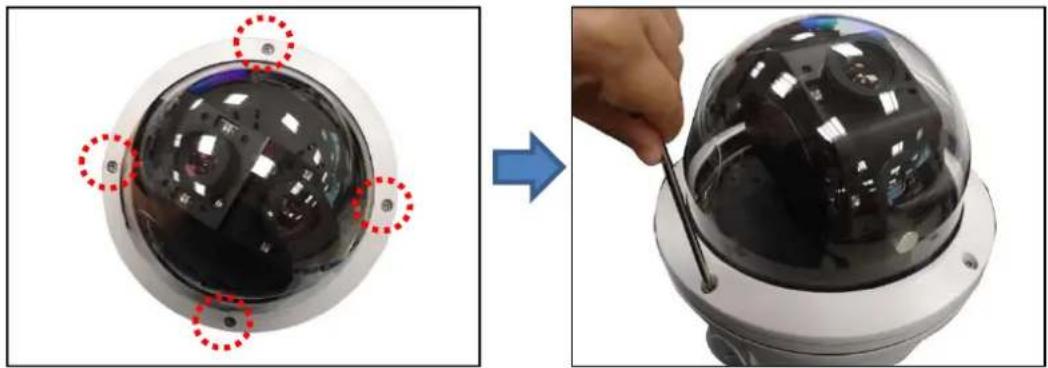
You need to open the dome cover to adjust the camera tilt and viewing angle, a memory card will be inserted in the camera, or when you need to remove the mount kit to install the camera on a flat surface without additional accessories.
Using the bundled wrench, loosen the four (4) screws securing the dome cover.
natural_image
Two-step photo showing a security camera module being adjusted, with red dotted circles highlighting the lens and a blue arrow indicating transformation (no text or symbols present)Insert the Memory Card (Optional)
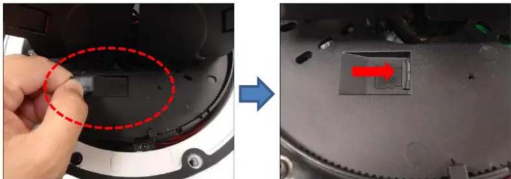
If a memory card will be used for local recording, do the following to insert the memory card.
- Open the dome cover. Locate the memory card slot on the base of the lens module.
- Insert the card with the card contacts facing down the card logo. Push the card until it clicks into place.
natural_image
Close-up of a robotic device showing a small component being removed, with a blue arrow indicating the process (no text or symbols visible)Installation Procedures
Installation procedures vary depending on the desired mounting solution. Cables may be connected first before mounting the camera or vice versa.
Below are the basic installation procedures when mounting the camera on the surface or with the use of a wall mount. Similar procedures apply when using other mounting options. For detailed information and other mounting solutions, check the website (http://www.acti.com/mountingselector).
NOTE: The following pictures are for reference only, actual camera and cable connections may slightly vary.
Mounting the Camera with Wall Mount
For the wall mount installation procedures below, PMAX-0345 is used as an example. Similar procedures can be applied for other accessories.
1. Drill the Required Holes
Use the drill template that came with your mounting accessory to drill the holes on the surface such as screw holes or cable hole.
2. Route the cables
Route the cables from the network side through the cable hole on the wall and into the wall mount, ready to be connected to the camera cables later.
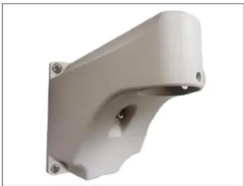
3. Install the Mounting Solution
Attach the wall mount to the wall. Make sure the converter ring on the wall mount is removed first because the cables will not pass through the converter ring.
natural_image
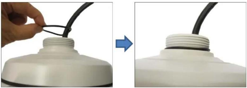
White plastic mechanical bracket with mounting holes and a central cavity (no text or symbols visible)4. Attach the Rubber Ring to the Mount Kit
Attach the bundled rubber ring to the top of the mount kit.
natural_image
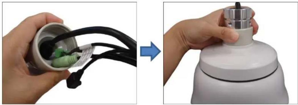
Close-up of a white plastic lamp bulb with a black cable being inserted, showing the process from before to after (no text or symbols visible)5. Attach the Wall Mount Converter Ring to the Camera
Insert the camera cables through the converter ring and secure the converter ring on the camera's mount kit.
natural_image
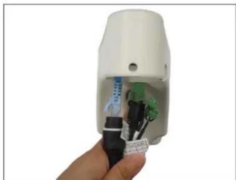
Two-step photo showing a hand holding a small container with green plug and black cable, before and after the process (no text or symbols visible)6. Insert and Connect the Cables
Connect the camera cables to the network side cables. Push the cables into the mount until it is completely inside the mount or the wall.
natural_image
Hand holding a white handheld device with internal components (no visible text or symbols)
CAUTION: The camera itself is waterproof, however take note that the cable connections are not. If the cable connections will be exposed outdoors, make sure to shield or adapt proper waterproofing methods. See Waterproof the Cable Connections on page 19.
DISCLAIMER: ACTi will not be responsible for camera damage caused by water entering the cable connections.
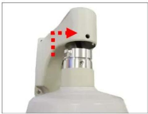
7. Mount the camera
- Align the gap on the camera to the tab inside the mounting solution and insert the camera through the mount. Attach the screws included in the wall mount package to secure the camera.
natural_image
Close-up of a white robotic arm with red arrow indicators and dotted lines, no visible text or symbols- Attach the two (2) screws included in the wall mount package to secure the camera.
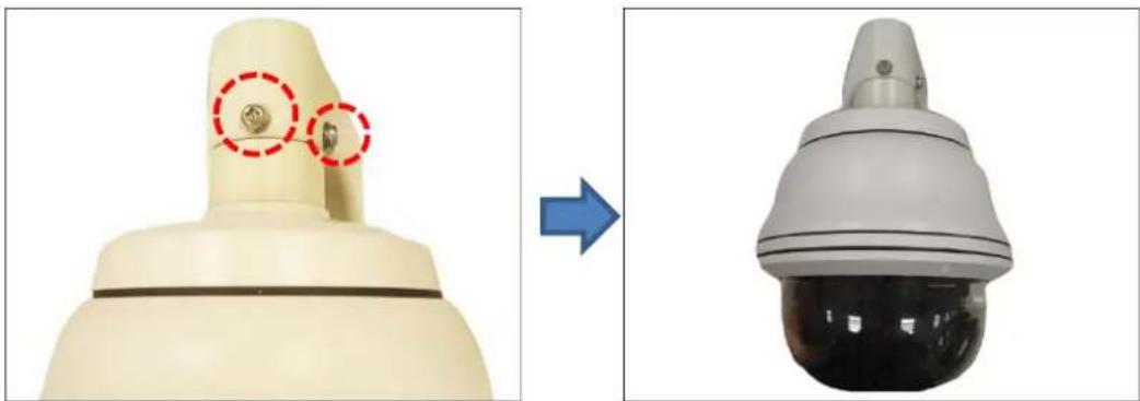
natural_image
Two views of a beige mechanical device: one showing a circular detail with red dashed circles, the other showing a spherical security camera (no text or symbols visible)- Adjust the camera tilt and viewing angle to complete the installation, see Adjust Camera Tilt and Viewing Angle on page 23.
Mounting the Camera Directly on the Surface
The camera can be directly mounted on a flat surface without using additional mounting accessories. To do this, you need to remove first the mount kit which comes attached to the camera, by default.
Remove the Mount Kit
- Remove the dome cover.
- Using a screwdriver, loosen the four (4) screws securing the camera module to the housing.
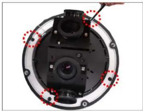
natural_image
Top-down view of a camera module with red dotted lines indicating alignment or adjustment points (no text or symbols visible)- Lift the camera module and pull out the cables through the mount kit and housing.
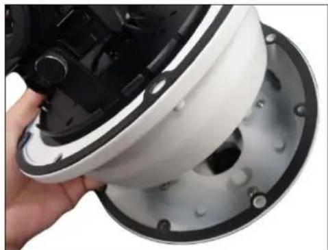
natural_image
Close-up of a hand holding a white helmet component, partially covered by a black plastic casing (no visible text or symbols)- Remove the four (4) screws securing the mount kit to the housing, and then detach the mount kit.
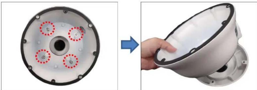
natural_image
Two views of a mechanical component: one showing a circular opening with red dashed circles, the other showing a hand holding a white bowl (no text or symbols visible)Mount the Camera
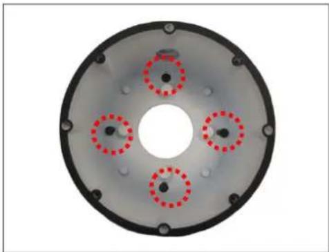
- Using the drill template that came with the camera, drill the holes on the surface such as screw holes and cable hole.
- Install the camera housing on the surface using four (4) screws.
natural_image
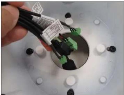
Circular mechanical component with four red-dotted circular features and central hole (no text or symbols)- Route the cables from the network side and the camera cables through the housing and then connect the cables.
natural_image
Close-up of a hand holding black cable and green connectors inside a white circular component (no visible text or symbols)
CAUTION: The camera itself is waterproof, however take note that the cable connections are not. If the cable connections will be exposed outdoors, make sure to shield or adapt proper waterproofing methods. See Waterproof the Cable Connections on page 19.
DISCLAIMER: ACTi will not be responsible for camera damage caused by water entering the cable connections.
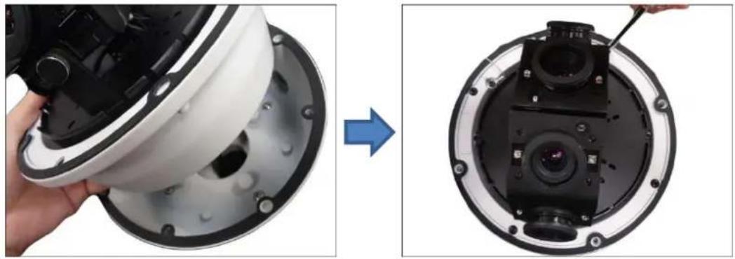
- Attach the camera module to the housing by securing the four (4) screws.
natural_image
Close-up of a white helmet with black plastic casing being processed, showing the camera module and adjustment (no text or symbols visible)- Adjust the camera tilt and viewing angle to complete the installation, see Adjust Camera Tilt and Viewing Angle on page 23.
Waterproof the Cable Connections
The camera itself is waterproof, however take note that the "pigtail" or cable connections are not.
If the camera is mounted directly on the ceiling/wall where the cables pass through the ceiling/wall, then your installation is complete and you do not need to waterproof the cable connections. However, if the camera is mounted where the cables may be exposed then it is recommended to waterproof the cable connections.
How to Use the Cable Gland
This section describes how to waterproof the cable-out or "pigtail" of the camera using the bundled cable gland.
Before connection, prepare the following materials:
• An exterior-grade Ethernet cable without the RJ-45 connector
- RJ-45 connector
- Crimping Tool
- Scissors
Perform the following to waterproof the "pigtail" using the cable gland:
- Detach the clamping nut from the cable gland:
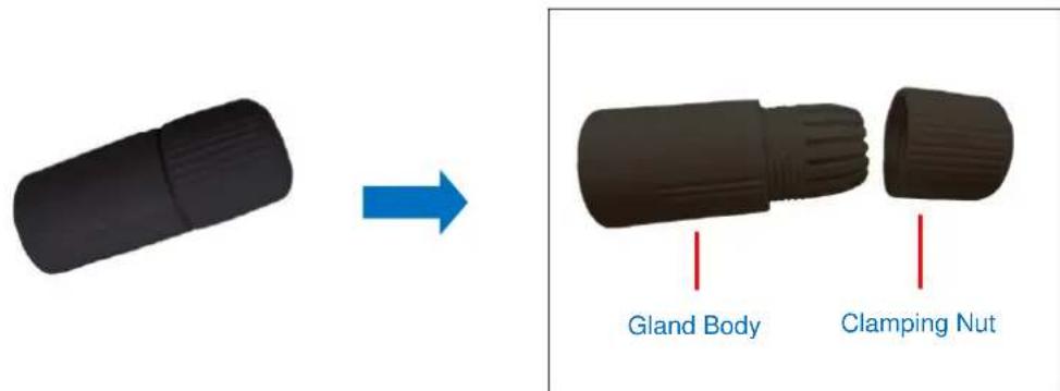
- Insert the clamping nut into the Ethernet cable (without connector).
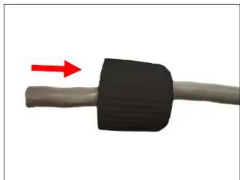
natural_image
Close-up of a black rubber plug with red directional arrow indicating compression (no text or symbols)- Insert the cable through the gland body.
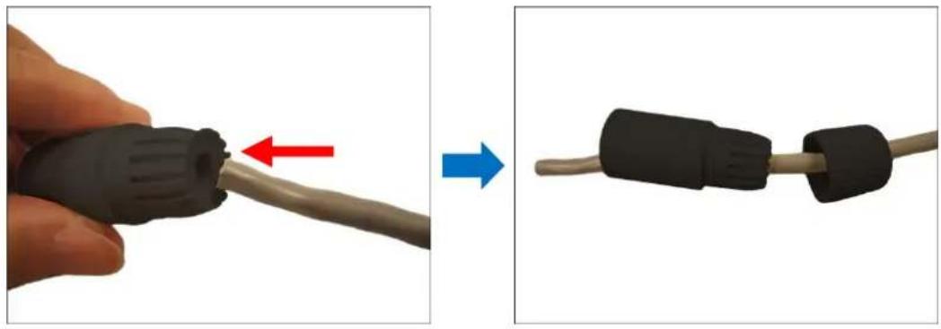
natural_image
Close-up of a black plastic plug being inserted into a cable, showing red and blue directional arrows (no text or symbols)- Attach the RJ-45 connector to the cable. For pin mapping and detailed instructions, see How to Attach the RJ-45 Connector for page 28 for detailed information.
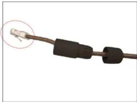
natural_image
Close-up of a black cable with a white connector, showing a circular detail (no text or symbols)- Connect the RJ-45 connector to the camera connector.
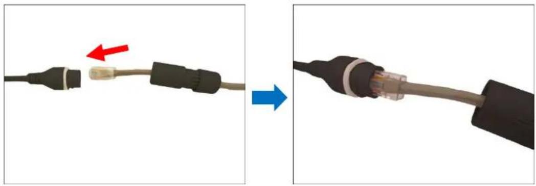
natural_image
Two images showing a cable being inserted into a socket, with red and blue arrows indicating direction (no text or symbols present)- Attach the gland body to the camera connector.
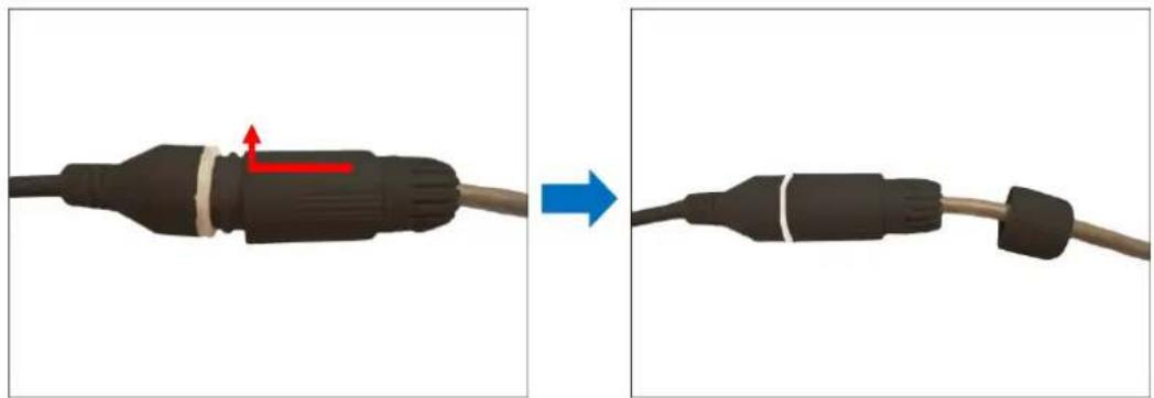
natural_image
Two-step diagram showing a black cable connector being adjusted to form a cable with a blue arrow indicating the motion (no text or symbols present)- Attach the clamping nut to the gland body to complete the cable solution.
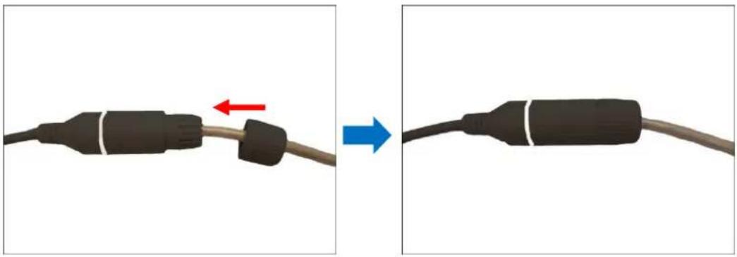
natural_image
Two-step diagram showing a black connector being connected to a cable, with red and blue arrows indicating direction (no text or symbols)NOTE: Make sure the clamping nut is tightly attached to the cable gland body and the sealing insert is squeezed tightly.
Connect to Network
Connect the other end of the network cable to a switch or injector. Then, connect the switch or injector to a network, PC, and a power source. See Power-over-Ethernet (PoE) connection example below.
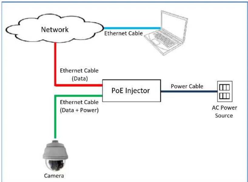
flowchart
graph TD
    A["Network"] -->|Ethernet Cable| B["Laptop"]
    A -->|Ethernet Cable (Data)| C["PoE Injector"]
    C -->|Power Cable| D["AC Power Source"]
    C -->|Ethernet Cable (Data + Power)| E["Camera"]
NOTE: Use only the supplied power adapter and power cord that came with the camera or the optional High PoE Injector available for purchase. Using other accessories not approved by the manufacturer may cause damage to the equipment.
See Accessing the Camera on page 30 for more information on how to access the Live View of the camera.
Adjust Camera Tilt and Viewing Angle
Based on the live view, you can adjust the viewing angle of the camera.
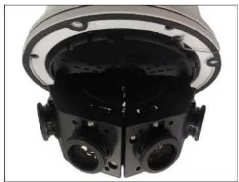
- Loosen the tilt adjustment screws, then tilt the lens module as needed.
- Tighten the tilt adjustment screws to fix its position.
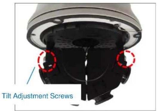
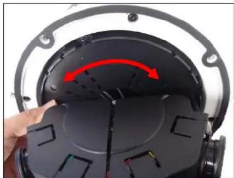
natural_image
Close-up of a black mechanical component with multiple circular features and mounting flanges (no visible text or symbols)- Move the module base to pan the camera.
natural_image
Close-up of a black electronic device with a red arrow indicating rotation or movement, being adjusted by hand (no text or symbols visible)Other Cable Connections
This section describes the procedures in preparing and connecting an external power adapter, optional Digital Input and Digital Output (DI/DO), such as alarms, sensors, etc., and Audio Input and Output devices. The use of these devices, however, is optional.
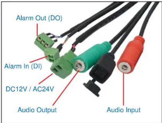
How to Connect a Power Adapter (Optional)
The camera can be powered by a Power over Ethernet (PoE) switch is IEEE802.3at (Class4) compliant. In case of using a non-PoE switch, you can purchase a power adapter and directly connect the camera to an external power supply.
WARNING: External power supply cannot be used with PoE simultaneously, or it may damage the camera.
Connect the wires of the power adapter to the corresponding pins on the terminal block of the power cable. See table below:
| POWER | Terminal Block Pin | |
| DC12~24V | AC24V | |
| Red | + | ~ |
| Black | - | ~ |
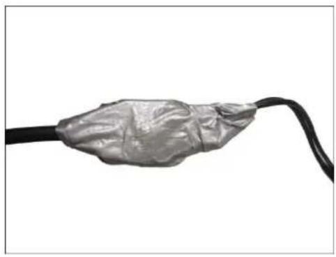
Make sure to protect the cable connection inside a junction box or wrap the connection using a waterproof tape (can be purchased in hardware stores) if cable connection will be exposed after installation.
How to Connect Digital Input / Digital Output Devices
Depending on your surveillance needs, you may need to connect digital input or output devices to your camera to trigger events or notifications.
Digital Input (DI) or alarm input devices can be used to notify the camera about an activity in the camera site. DI can be triggers of events. For example, you can connect a “panic button” to the camera; as such when the panic button is pressed, the alarm signal will be sent through the camera. Other common DI device applications are emergency button, smoke detector, passive infrared sensor, etc.
Digital Output (DO) or alarm output devices are external devices that are activated by the camera upon an event inside the camera. For example, you can connect an “alarm horn” to the camera; as such when an event occurs inside the camera (e.g. detected intruder), the alarm horn will sound. Other common DO device applications are motion-triggered lights, electric fence, magnetic door locks, etc.
Connecting DI/DO Devices
Map the pins to the terminal block of the DI (Alarm input) or DO (Alarm output) cables as shown on the table below. Loosen the screw and insert the wire through the pin slot on the terminal block, then tighten the screw to secure the wire.
| ALARM OUT (DO) | Terminal Block Pin |
| Purple | NC |
| Green | COM |
| White | NO |
| ALARM IN (DI) | Terminal Block Pin |
| Blue | + |
| Orange | - |
After mapping the wires to the terminal block, connect the terminal block to the DI/DO connectors of the camera and be sure to protect the cable connection inside a junction box or wrap the connection using a waterproof tape (can be purchased in hardware stores) if cable connection will be exposed after installation. Sample below:
natural_image
Close-up of a metallic cable with a damaged cover, isolated on white background (no text or symbols)NOTE: For more information on DI/DO connections, please refer to the article All About Digital Input and Digital Output downloadable from http://Download.acti.com?id=516.
How to Connect Audio Devices
The camera comes with audio input / output jacks to connect a microphone or speaker to the camera. The audio jacks are covered with a rubber protection.
If using an audio input device, such as a microphone with a built-in amplifier, connect the device to the Audio Input jack (PINK) of the camera. If using an audio output device, such as a speaker, connect the device to the Audio Output jack (LIGHT GREEN) jack of the camera.
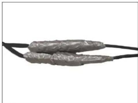
If the camera is installed outdoors, be sure to wrap the audio connectors with Waterproof tape (can be purchased in hardware stores).
DISCLAIMER: ACTi will not be responsible for damaged cameras due to water leakage caused by improper waterproofing of cables.
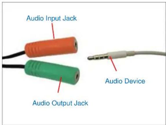
NOTE 1: Make sure that the connected audio input device has a built-in amplifier. Connecting an ordinary microphone will dwarf sounds and will result in inaudible recording.
NOTE 2: If the audio connectors will not be used, leave the rubber caps on to avoid water and dust from entering the connectors.
Be sure to protect the audio cable connections inside a junction box or wrap with waterproof tape (can be purchased in hardware stores).
natural_image
Close-up of two metallic wire cables with coiled leads, isolated on white background (no text or symbols)How to Attach the RJ-45 Connector
- Prepare the following tools:
a. RJ-45 connector
b. Crimping tool
c. Scissors
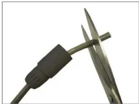
- Cut about one (1) inch into the plastic sheath from the end of the cable.
natural_image
Close-up of a pair of scissors cutting metal wire, no text or symbols visible- Unwind the wires and arrange them according to the color sequence below.
 | 1 | Stripe Orange |
| 2 | Orange | |
| 3 | Stripe Green | |
| 4 | Blue | |
| 5 | Stripe Blue | |
| 6 | Green | |
| 7 | Stripe Brown | |
| 8 | Brown |
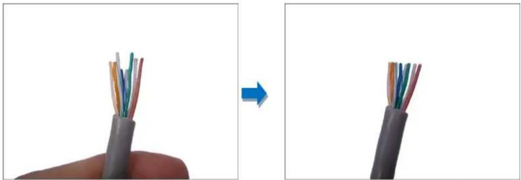
- Straighten out the wires and use the scissors to make a straight cut 12 inch from the cut end.
natural_image
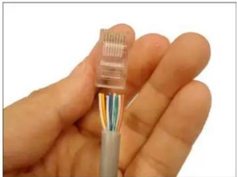
Close-up of a cable with exposed internal wires being removed from a blue arrow (no text or symbols)- With the RJ-45 connector tab facing down, push down the wires into the connector all the way to the end.
natural_image
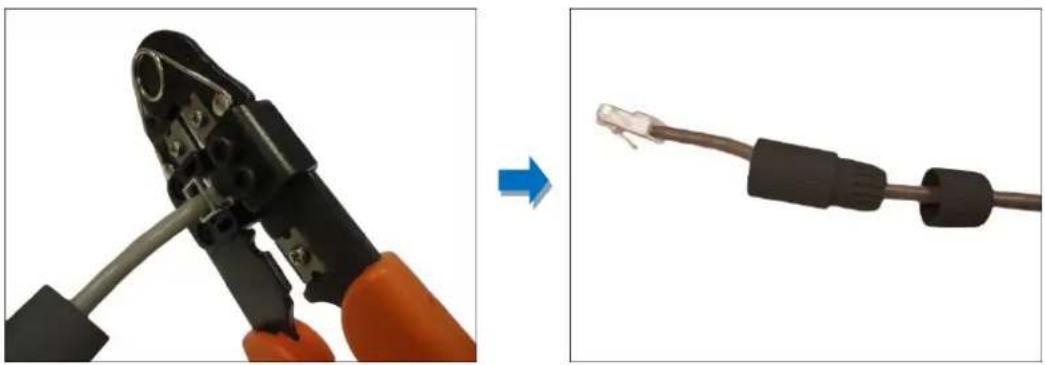
Close-up of a hand holding a transparent cable with multicolored wires (no text or symbols visible)- Place the connector into the crimping tool, and cinch down to secure the RJ-45 connector to the Ethernet cable.
natural_image
Two-step diagram showing a hand using a wire to connect a pliers and a cable with a connector (no text or symbols present)Accessing the Camera
Configure the IP Addresses
In order to be able to communicate with the camera from your PC, both the camera and the PC have to be within the same network segment. In most cases, it means that they both should have very similar IP addresses, where only the last number of the IP address is different from each other. There are 2 different approaches to IP Address management in Local Area Networks – by DHCP Server or Manually.
Using DHCP server to assign IP addresses
If you have connected the computer and the camera into the network that has a DHCP server running, then you do not need to configure the IP addresses at all – both the camera and the PC would request a unique IP address from the DHCP server automatically. In such case, the camera will immediately be ready for the access from the PC. The user, however, might not know the IP address of the camera yet. It is necessary to know the IP address of the camera in order to access it using a Web browser.
The quickest way to discover the cameras in the network is to use the simplest network search, built in the Windows system – just by pressing the “Network” icon, all the cameras of the local area network will be discovered by Windows, thanks to the UPnP function support of our cameras.
In the example below, the camera model that has just been connected to the network is successfully found.
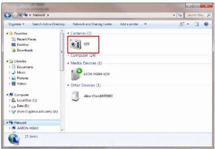
Double-click the mouse on the camera model name, the default browser of the PC is automatically launched and the IP address of the target camera is already filled in the address bar of the browser.
If you work with our cameras regularly, then there is even a better way to discover the cameras in the network – by using IP Utility. The IP Utility is a light software tool that can not only discover the cameras, but also list lots of valuable information, such as IP and MAC addresses, serial numbers, firmware versions, etc, and allows quick configuration of multiple devices at the same time.
Search and download IP Utility for free from http://www.acti.com/DownloadCenter.
When you launch IP Utility, the list of connected cameras in the network will be shown. See sample illustration below:
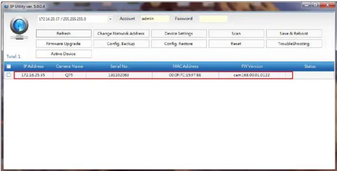
The camera model name is shown on the list. Double-click on the IP address to automatically launch the default browser of the PC with the IP address of the target camera already filled in the address bar of the browser.
Use the default IP address of the camera
If there is no DHCP server in the given network, the user may have to manually assign the IP addresses to both the PC and the camera to make sure they are in the same network segment.
When the camera is plugged into the network and it does not detect any DHCP services, it will automatically assign itself a default IP:
192.168.0.100
Whereas the default port number would be 80. In order to access that camera, the IP address of the PC has to be configured to match the network segment of the camera.
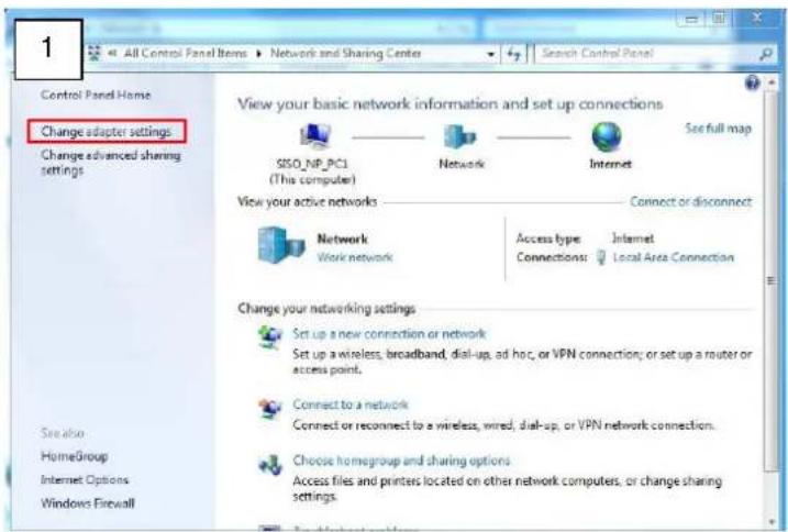
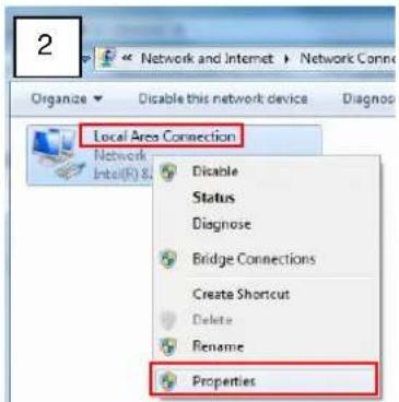
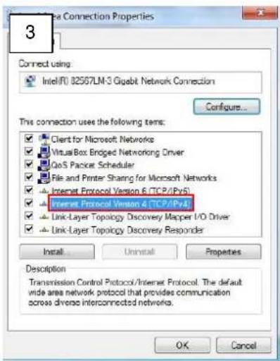
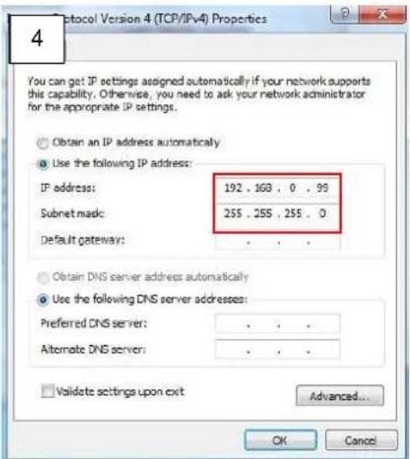
Manually adjust the IP address of the PC
In the following example, based on Windows 7, we will configure the IP address to 192.168.0.99 and set Subnet Mask to 255.255.255.0 by using the steps below:
Manually adjust the IP addresses of multiple cameras
If there are more than one camera to be used in the same local area network and there is no DHCP server to assign unique IP addresses to each of them, all of the cameras would then have the initial IP address of 192.168.0.100, which is not a proper situation for network devices – all the IP addresses have to be different from each other. The easiest way to assign cameras the IP addresses is by using IP Utility:
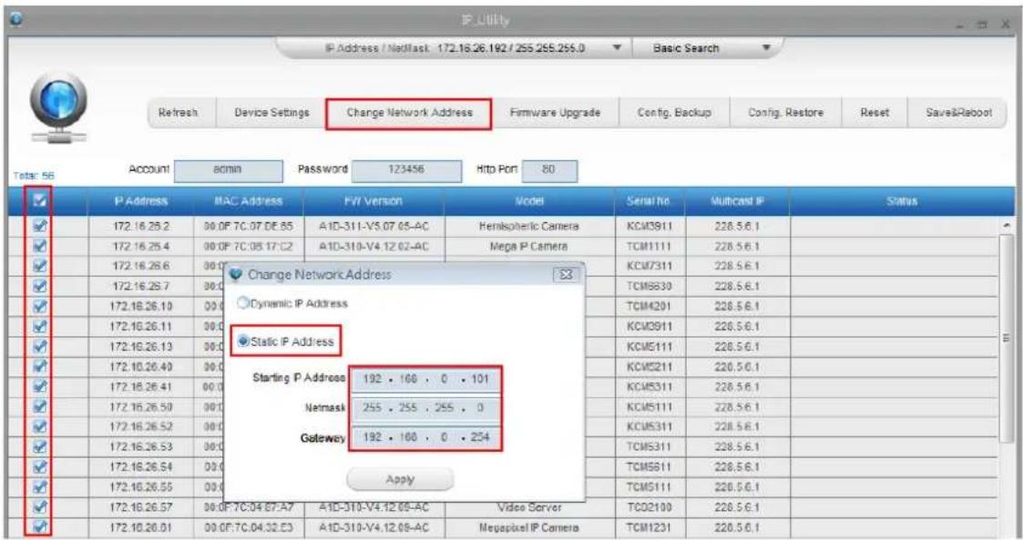
With the procedure shown above, all the cameras will have unique IP addresses, starting from 192.168.0.101. In case there are 20 cameras selected, the last one of the cameras would have the IP 192.168.0.120.
Later, by pressing the "Refresh" button of the IP Utility, you will be able to see the list of cameras with their new IP addresses.
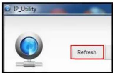
Please note that it is also possible to change the IP addresses manually by using the Web browser. In such case, please plug in only one camera at a time, and change its IP address by using the Web browser before plugging in the next one. This way, the Web browser will not be confused about two devices having the same IP address at the same time.
Access the Camera
Now that the camera and the PC both have their unique IP addresses and are under the same network segment, you can use Microsoft Internet Explorer or other browsers as indicated on the Product Specification on the PC to access the camera.
When using Internet Explorer browser, the ActiveX control for video stream management will be downloaded from the camera directly – the user just has to accept the use of such control when prompted so. No other third party utilities are required to be installed in such case.
The following examples in this manual are based on Internet Explorer browser in order to cover all functions of the camera.
Assuming that the camera's IP address is 192.168.0.100, you can access it by opening the Web browser and typing the following address into Web browser's address bar:
http://192.168.0.100
Upon successful connection to the camera, the user interface will appear. For first time use, you need to setup the administration password.
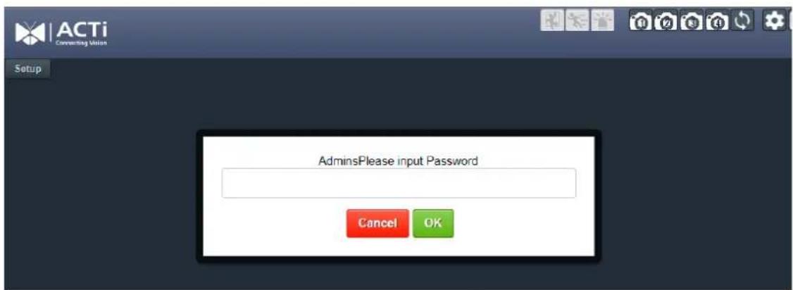
Re-type to confirm the password.
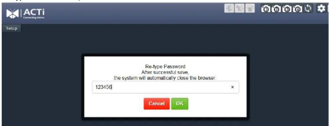
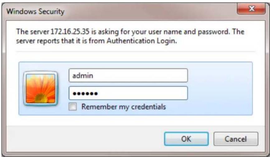
If an empty page opens, close the page and access the camera again. The user interface will prompt for the account and password for login.
Type the default account: "admin", and type the password you have just setup.
For further operations, please refer to the Firmware User Manual.

ACTi
Connecting Vision
Copyright © 2020, ACTi Corporation All Rights Reserved
7F, No. 1, Alley 20, Lane 407, Sec. 2, Ti-Ding Blvd., Neihu District, Taipei, Taiwan 114, R.O.C.
TEL: +886-2-2656-2588
FAX: +886-2-2656-2599
Email: sales@acti.com
- Outdoor Multi-Imager Dome Hardware Manual
- Table of Contents
- Precautions 4
- Introduction......7
- Before Installation.... 12
- Installation Procedures....13
- Other Cable Connections....23
- Accessing the Camera 30
- Precautions
- Read these instructions
- Heed all warnings
- Servicing
- Trademarks
- Liability
- Federal Communications Commission Statement
- European Community Compliance Statement
- Safety Instructions
- Cleaning
- Attachments
- Water and Moisture
- Damage Requiring service
- Safety Check
- Introduction
- List of Models
- Package Contents
- Physical Description
- Mounting Options
- Before Installation
- Open the Dome Cover
- Insert the Memory Card (Optional)
- Installation Procedures
- Mounting the Camera with Wall Mount
- Drill the Required Holes
- Route the cables
- Install the Mounting Solution
- Attach the Rubber Ring to the Mount Kit
- Attach the Wall Mount Converter Ring to the Camera
- Insert and Connect the Cables
- Mount the camera
- Mounting the Camera Directly on the Surface
- Remove the Mount Kit
- Mount the Camera
- Waterproof the Cable Connections
- How to Use the Cable Gland
- Connect to Network
- Adjust Camera Tilt and Viewing Angle
- Other Cable Connections
- How to Connect a Power Adapter (Optional)
- How to Connect Digital Input / Digital Output Devices
- Connecting DI/DO Devices
- How to Connect Audio Devices
- How to Attach the RJ-45 Connector
- Accessing the Camera
- Configure the IP Addresses
- Using DHCP server to assign IP addresses
- Use the default IP address of the camera
- 192.168.0.100
- Manually adjust the IP address of the PC
- Manually adjust the IP addresses of multiple cameras
- Access the Camera
- http://192.168.0.100
- ACTi
- Connecting Vision
Brand : ACTi
Model : Q75
Category : Security Camera