iP-40 - Video projector Elmo - Free user manual and instructions
Find the device manual for free iP-40 Elmo in PDF.

| Product Type | Video Projector |
| Brand | Elmo |
| Model | iP-40 |
| Dimensions (W x D x H) | 300 x 200 x 100 mm |
| Weight | 2.5 kg |
| Power Supply | AC 100-240V, 50/60Hz |
| Power Consumption | 250 W (max) |
| Light Source | UHP Lamp |
| Lamp Life | 2000 hours (standard mode) |
| Resolution | XGA (1024 x 768) |
| Brightness | 3000 ANSI lumens |
| Contrast Ratio | 2000:1 |
| Projection Lens | Manual zoom and focus |
| Inputs | HDMI, VGA, Composite, S-Video, USB |
| Outputs | Audio out (3.5mm), RS-232C |
| Operation Temperature | 5°C to 35°C |
| Noise Level | 35 dB (standard mode) |
| Maintenance | Clean air filter every 100 hours; replace lamp when prompted |
| Safety | Overheat protection, auto off after 30 min idle |
| Spare Parts | Replacement lamp (ELPLP67), air filter |
Frequently Asked Questions - iP-40 Elmo
User questions about iP-40 Elmo
0 question about this device. Answer the ones you know or ask your own.
Ask a new question about this device
Download the instructions for your Video projector in PDF format for free! Find your manual iP-40 - Elmo and take your electronic device back in hand. On this page are published all the documents necessary for the use of your device. iP-40 by Elmo.
USER MANUAL iP-40 Elmo
Partner Business Department, Manufacturing Equipment & Information Products Sales Division NIPPON AVIONICS CO., LTD.
Gotanda Kowa Bldg., 1-5, Nishi-Gotanda 8-chome, Shinagawa-ku, Tokyo Japan
Zip code: 141-0031
Tel: +81-3-5436-0625 Fax: +81-3-5436-0639
Customer Support Center, Solution Products Division
1-1 KOYATO 2-CHOME SAMUKAWA-MACHI
KOZA-GUN KANAGAWA, JAPAN
Zip code: 253-0103
Tel: +81-467-73-4426
E-mail: support_ip@avio.co.jp
URL: http://www.avio.co.jp
To customers : Enter the name and date of the store where you purchased this product. This information will be useful when you ask your dealer for repair.
• Date of Purchase (year, month, day)
- Store of Purchase
Telephone Number : ( )
7001155-R011①
A Proposal for New Presentations

Intelligent Projector
User's Manual
iP-40

natural_image
Line drawing of a projector with ventilation slots and a flat panel (no text or symbols)Information on the included manuals
These manuals have been prepared to allow you to take full advantages of the set's functions.
Select the manual suited to your purpose.
• IP-40 manual (this manual)
Includes information on the operation and handling of the projector (IP-40SE/IP-40BE).
• iP Viewer Software Quick Reference
Includes a concise description of handling of the "iP Viewer" presentation software.
• IP Viewer Software Manual (PDF format)
Includes more detailed instructions than the Quick Reference. Select according to your purpose.

The iP Viewer function is only available with model iP-40SE.
Note: This equipment has been tested and found to comply with the limits for a Class A digital device, pursuant to Part 15 of the FCC Rules. These limits are designed to provide reasonable protection against harmful interference when the equipment is operated in a commercial environment. This equipment generates, uses, and can radiate radio frequency energy and, if not installed and used in accordance with the instruction manual, may cause harmful interference to radio communications. Operation of this equipment in a residential area is likely to cause harmful interference in which case the user will be required to correct the interference at his own expense.

Disposing of your used Avio product
In the European Union
EU-wide legislation as implemented in each Member State requires that used electrical and electronic products carrying the mark (left) must be disposed of separately from normal household waste. This includes projector or electrical accessories, such as remote control or cable.
When you dispose of such products, please follow the guidance of your local authority or ask the shop where you purchased the product, or if applicable, follow any agreements made by between you and Axis.
The mark on electrical and electronic products only applies to the current European Union Member States.
Outside the European Union
If you wish to dispose of used electrical and electronic products outside the European Union, please contact your local authority and ask for the correct method of disposal.

A Proposal for New Presentations
Intelligent Projector
User's Manual
iP-40
English
Deutsch
Français
中国语
한국어
Warning
This is a Class A product. In a domestic environment this product may cause radio interference in which case the user may be required to take adequate measures.
Thank you for your purchase of an AVIO product.
Please read this manual carefully in order to use the projector properly.
After reading this, please keep it in a safe place together with the warranty sheet.
Features of the iP-40
- Very versatile six-in-one projector. A projector for the multimedia age.
- Projection of documents, catalogs, and other printed materials. Printed materials can be projected directly without the creation of OHP film.
- Projection of personal computer screen images Detailed presentations can be made using a personal computer.
- The video images of video tape decks, DVDs and other equipment can be projected. This permits the creation of presentations that are visually appealing.
- Projection images can be imported to a personal computer connected via USB.
- An image that has been scanned to a personal computer can be written on as one pleases using a tablet or another device and while doing so the image can be projected.
- The SD memory card can be used to make presentation without a PC. * This function is available only for the iP-40SE model only. You must use a dedicated tool to save data in the SD memory card.
• High definition, high reliability thanks to DLP ® technology
You can change the mode according to the picture or video image projected.
- Easily understood, simple operation for everyone
One button operation simply switches the projection of printed material, personal computer screen, and video image.
- Designed for a conservation of resources which offers excellent cost performance
The creation of OHP film is not required. This allows a reduction of wasteful time and costs.
• Super-thin, stylish body
The iP-40 features a super-thin body for a projector having a built-in OHP function which reflects the advanced technology inherent in the design. Offers an easy fit when in use or when stored.
• Expressive color pictures
High resolution, 4,130,000 pixel CCD camera is built in. It provides faithful and clear reproduction of the detailed neutral tones of color documents with its full-color 16.77 million colors.
- Enlarged display without changing the screen size
When projecting documents having small characters that were not created for presentations, such as catalogs and word-processed documents, the iP-40 can enlarge the document without changing the screen size to provide an easy-to-view display.
- Provided with display functions for compressed or enlarged PC screen
Screens of resolution more than 1024 × 768 dots are displayed compressed to 1024 × 768 dots without any loss in character quality. Such as 640 × 480 resolution screens can also be enlarged to 1024 × 768 dots.
About Trademarks
NEC and the PC-9800 series are trademarks of NEC Corporation.
IBM and PC/AT are trademarks or registered trademarks of International Business
Machines Corporation.
Macintosh and Power Book are trademarks of Apple Computer Inc.
Windows is a trademark of U.S. Microsoft Corporation.
DLP® and the DLP logo are registered trademarks of Texas Instruments.
Adobe, Adobe logo, and Acrobat are trademarks of Adobe Systems Incorporated.
The SD logo is a registered trademark.
Warnings and Safety Precautions
Warning Symbols
To alert the user to important safety precautions, the following symbols are used in this manual and on the product. Make sure you understand what these symbols mean before operating the projector.
| ⚠ WARNING | Death or serious injury may result if this warning is ignored. |
| ⚠ CAUTION | Injury or damage to the equipment may result if this warning is ignored. |
| NOTE This | indicates an item that you should take care of when handling your projector. |
| This symbol alerts the user to high voltage that could cause electric shock. | |

WARNING
- If a fault occurs:
- If you detect smoke, or a strange smell or sound, immediately disconnect the power cable.
It is dangerous to continue using the projector after a fault occurs. Return the projector to the dealer where it was purchased for repair.
- Avoid placing the projector near dangerous substances.
- Make sure that no metallic or flammable material can get into the projector through the air vents.
- Do not place any objects containing water on top of or next to the projector.
- If foreign matter gets inside the projector:
- If foreign matter such as water or metal gets inside, immediately disconnect the power cable.
It is dangerous to continue using the projector when foreign matter gets inside. Return the projector to the dealer where it was purchased for servicing.
- Do not remove the cabinet.
- Do not remove the cabinet. There are high-voltage components inside and touching these parts could cause electric shock, or damage the equipment.
● Handle the power cable safely.
- Do not place any heavy objects on top of the power cable.
Damage to the power cable can cause wire breakage, fire, or electric shock.
- Do not pull the power cable when disconnecting the power plug.
Pulling the cable may break the wires or cause fire or electric shock. Always hold the plug itself when pulling it out of the power outlet.
- Do not damage the power cable. If the power cable is damaged (e.g. the core is exposed or cut), contact the sales office of purchase. (charged) it could cause fire or electric shock if you continue using the damaged power cable.
- Do not peep into the lens.
- Do not peep into the lens of the projector during operation. The powerful rays passing through the lens could damage the eyes.
- Do not put the projector in unstable places.
- Do not put the projector in unstable places such as on unstable desks or slopes.
Doing so could cause the projector to drop or turn over, resulting in injury.
- Do not use any voltages other than specified.
- Do not use any voltages other than specified. Doing so could cause fire or electric shock.
- Do not beat the glass surface
- Do not beat the glass surface over the scanner. Doing so may break the glass, resulting in injury.
- Do not get on the unit. Do not put a heavy matter on it.
- Do not get on or put a heavy matter on the unit. Negligence to observe it causes damage or a failure.
Depending on the case, the glass face may be broken, causing injury.
- Do not touch the air vents or lamp cover
- The air vents, lamp cover, and peripheral surfaces may be high temperature during operation or just after the light is turned off.
Do not touch those for a long time.
- The area around the projector's exhaust outlet gets very hot. Do not place the projector on tables, desk mats, etc., that are vulnerable to heat. The table may be discolored, the desk mat warped, etc.
- Do not block the lens front
- Do not block the lens front during operation.
The powerful rays passing through the lens may cause fire or burns if you put anything in front of the lens or block the lens with your hand during operation.
Warning
Please check the rating of the power cable.
Prior to using a power cable, please make sure that the cable is fully compliant with the power ratings and the type of the plug in the area and, if not, purchase proper power cable for the area. Do not use the cables for 120V rating to 220V power source.
Using improper cable may cause fire or electrical shock to human body.

CAUTION
- Installation
- Avoid installing the projector in places where it may be exposed to:
- On tables, etc., that are vulnerable to heat.
- Strong vibrations
- Soot or steam
- Direct sunlight or near a heater (35°C/95°F or higher)
- High humidity or dust
- Extreme cold (0°C/32°F or lower)
- Strong magnetic or electric field generated from a nearby appliance
- Wobbling on an unstable surface
- Do not block the air vents.
- Do not block the air vents with cloth or an object. When you put anything around the unit, be sure to ensure a space of 10 cm/4 inches or more between the unit and the air vent. Be sure to prevent paper or cloth from blocking the air vent at the bottom of the unit. If blocked, the internal temperature may increase, resulting in malfunctions.
- Do not bump the projector.
- Avoid bumping the projector when moving or handling. Shocks can cause damage.
- Care of the projector
- To prevent risk of accidents, always disconnect the power plug before cleaning the projector.
- Clean the lens surface with a commercial blower or lens cleaning paper.
Wiping with tissue paper or a handkerchief can damage the lens. - To clean the cabinet, operation panel, and glass surface, wipe gently with a soft cloth. For particularly dirty spots, soak the cloth in a neutral detergent mixed in water, wring out well and wipe off the dirt, then use a dry cloth to wipe dry.
- Do not wipe the projector with any volatile solvent such as benzine or thinner.
Solvents can cause surface deformation or flaking of the paint.
If using an impregnated cloth, follow the instructions of the cloth.
- Avoid scratching the glass surface.
• Take care not to scratch the glass surface of the scanner with hard or pointed objects.
Scratches on the glass may distort the projected image.
- Battery
- When inserting battery in the remote control, note the polarity (plus and minus signs) and insert correctly as indicated. Inserting a battery in a wrong direction can cause rupture or leakage, and could result in fire and injury or soil the surrounding area.
- Do not use coin battery other than the type specified for the equipment. Incorrect battery usage could result in rupture or leakage, and could cause fire and injury.
- Do not heat, break open, burn, or immerse the battery. Battery rupture or leakage could cause fire and injury.
- Perchlorate Material-special handling may apply.
See www.dtsc.ca.gov/hazardouswaste/perchlorate/index.cfm.
- Dew condensation
- Abruptly moving the unit to a place where there is a great temperature difference causes dew condensation on the main unit.
Projection under a dew condensed state causes a failure.
• Servicing and cleaning
- Have the internal components cleaned by a retailer about once a year. There is a risk of fire or faulty operation if the inside of the projector gets dusty and is not cleaned for a long time. For best results, the projector should be serviced before the wet season brings damp conditions. Cleaning charges are at the discretion of the retailer.
- If not using the projector for a long period:
- If you do not plan to use the projector for a long time, disconnect the power cable for safety.
- Disposal
- Follow the recommendations of your local authority when disposing of the projector.
- Transporting the projector
- Use the special packaging when transporting the projector. The manufacturer cannot accept responsibility in the event of damage or accident if other packaging is used.
- Use the special packaging no more than two times. Repeated usage reduces the shock absorbency of the packaging and can lead to damage or accident.
- Contact the retailer if you require new packaging.
- Lamp implosion
- A DC type Super High pressure lamp is used in this projector and it is rare for the lamp to explode during use. The unit is also designed to forcibly turn off the lamp because there is a high possibility that the lamp will break if it is used beyond the lamp usage of 2000 hours (Refer to pages E-43 and E-45).
Note the following things
- A sound occurs because the internal pressure of the Super High pressure lamp gets extremely high. The unit is designed so that no pieces of glass come out of it when the lamp explodes.
• However, the gas inside of the lamp can escape and looks like white smoke.
It will not cause any fire.
Remedy
- If a lamp explodes in a product, there will be pieces of lamp inside. Do not replace the lamp. Return the product to the sales office or agent of purchase. Even though the lamp has exploded, never try to replace the lamp by yourself. The lamp pieces could cause injury.
- Replacing the lamp
- Be sure to turn the lamp off and disconnect the power cable when the fan stops, and wait an hour or more before replacing the lamp. Replacing the lamp during operation or just after the power is turned off may cause burns due to heat. Refer to "Replacement of the Lamp Unit" on page E-43 for the procedure.
- Replacing / cleaning the air filter
- Be sure to disconnect the power cable when the cooling fan stops before removing the air filter. Removing the air filter while the cooling fan is rotating could cause a accident. Refer to "Cleaning the Air Filter" on page E-46 for the procedure.
- Avoiding malfunctions and accidents
- Adjust the Adjustable feet to keep the projector horizontally. Using the projector in a tilted status may cause injury if it rolls over. Refer to "Adjusting the Tilt" on page E-22 for the adjusting procedure.
- Do not do the followings
- Do not put anything heavy on the projector.
- Do not step on the projector, rack, or stand. Do not hold or hang on the projector.
Doing so could cause the projector to roll over or break, resulting in injury.
Especially be careful if small children are near. - Do not use the rack unless the casters are locked when placing the projector on a rack with casters.
Doing so may cause the projector to move or roll over, resulting in injury. - Do not turn the lamp on/off within one minute after it is turned off/on. Extremely high voltage is generated in the lamp just after it is turned on. Turning the lamp on/off too frequently could cause the lamp to deteriorate or break, resulting in malfunctions of the projector.
- Do not project an image with the lens cap attached.
- Do not use with the air filter removed. Doing so could cause damage or malfunction.
- Do not hold by the focus adjustment ring.
Doing so could cause damage or malfunction.
- Moving the projector
The unit is meant to be used in a stationary position.
- Be sure careful of the glass surface at moving the projector while holding the handles.
- If the document cover is not inserted enough, it may get loose and fall off while you carry it.
- Avoid swinging it around or treating it roughly.
- Care of the power cable and plug
- Do not put the power cable near a heater.
Doing so could cause the sheath of the cable to melt down, resulting in fire or electric shock. - Do not connect or disconnect the power cable with wet hands. Doing so could cause electric shock.
- Be sure to pull out the power cable and disconnect any cable connections between units and release the anti-theft lock before moving the projector.
Moving the projector with cables connected may cause fire or electric shock if the cables are damaged. - If you do not plan to use the projector for a long time, disconnect the power cable for safety.
- DO NOT REMOVE ANY SCREWS except the lamp cover screw and two lamp unit screws. Otherwise you could receive an electric shock.
- About the projection lamp and other optical parts
The projection lamp and other optical parts are expendables. When used for a long time, repair and replacement will be necessary. Please contact a customer support center for details.
- Keep your face away from the exhaust vents.
- If the lamp is broken, dust may enter your eyes or mouth. Be sure to keep your face away from the exhaust vents. Otherwise, it may result injury. (If foreign matters enter the eyes, consult an ophthalmologist.)
Safety Precautions ...... E-3
A Check of the Supplied Items and the Names of the Parts ...... E-7
Supplied Parts Check E-7
Names and Functions of the Parts (Projector) ...... E-8
Names and Functions of the Parts (Input Connectors) ...... E-10
Names and Functions of the Parts (Operation Panel) ...... E-11
Names and Functions of the Parts (Remote Control) ...... E-12
Operation of the Remote Control E-13
Battery Replacement E-13
Procedure Up to Projection ...... E-14
Projection Distance and Screen Size ...... E-15
Connections with the Personal Computer ....E-16
Basic Connections ...... E-16
Connections with Personal Computers ...... E-16
Personal Computer Input Connector ...... E-17
When the Image of the Personal Computer Screen Is Not Projected .... E-18
Table of Supported Input Signals E-19
Connections with Video Equipment ...... E-20
Connection of the Power Cable and On/Off Switching E-21
Switch On the Power ...... E-21
Switch Off the Power ...... E-21
Adjustment of the Projection Image ...... E-22
Adjusting the Projection Image ...... E-22
Making Focus/Zoom Adjustments ...... E-22
Adjusting the Tilt (Slant) E-22
Regular Operation ...... E-23
Select the Input E-23
Changing the Orientation of the Projection Image .. E-23
Enlarging and Reducing the Projection Image ..... E-24
Adjusting the Brightness E-25
Capturing the Projection Image/ Still Image Display ..... E-26
Making presentation using incorporated memory or SD memory card ....E-28
Using the SD memory card image to make presentation ....E-30
Transferring Captured Images E-32
Adjusting the Volume E-32
Displaying the Pointer ...... E-33
Deleting the Projection Image and Audio ...... E-33
Method of OHP Operation E-34
Attaching the Document Cover ...... E-34
Preparation of the Projection Document ...... E-34
Reading Size of Projection Documents ...... E-34
Menu Configuration ...... E-35
Menu Operation Method ...... E-36
Names and Functions of the Buttons Used in Menu Operation ...... E-36
Names and Functions of the Menu Parts ...... E-36
Method of Menu Operation E-37
Menu Description ...... E-39
Pointer • Screen E-39
History menu E-40
Image adjustment ...... E-41
Settings E-43
Maintenance E-45
Fault Protection E-45
Replacement of the Lamp Unit ...... E-47
Cleaning the Air Filter E-50
Troubleshooting E-51
Repair Service E-52
Specifications E-53
Viewing the iP Viewer's Operating Instructions .... E-54
A Check of the Supplied Items and the Names of the Parts
Supplied Parts Check
Please check that the supplied parts are included.
text_image
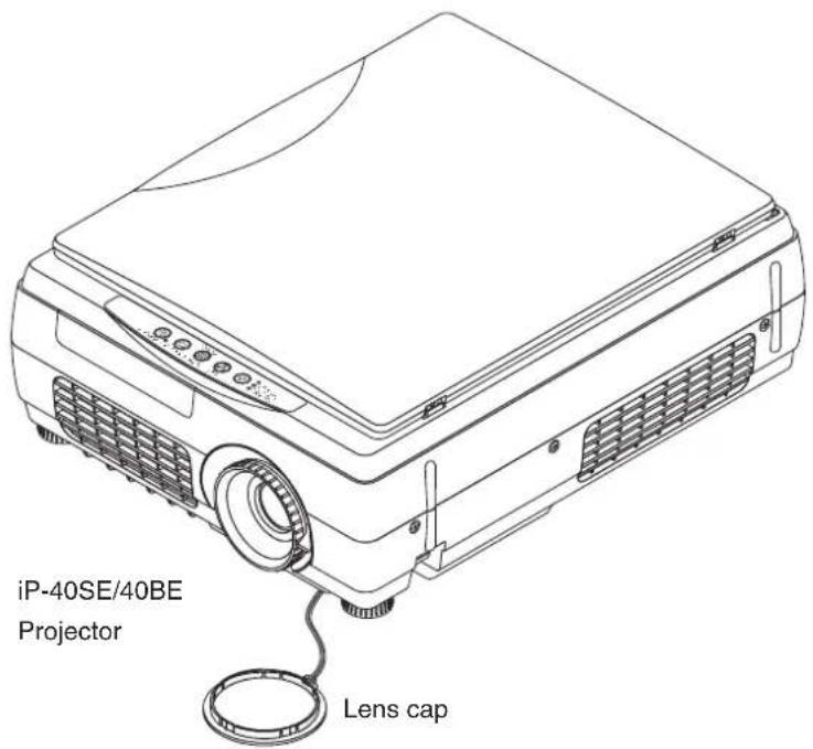
iP-40SE/40BE Projector Lens cap
text_image
Pull out the sheet before use.Remote control
Coin-type lithium battery: CR2025
(Inside the remote control)
natural_image
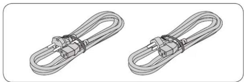
Two identical wire harnesses with terminal connectors, shown from different angles (no text or symbols)Power cable (3 m)
* Power cable for Singapore is different from the above one. (Refer to the page E-55.)
natural_image
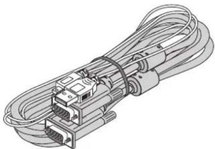
Illustration of a multi-pin cable with multiple connectors and connectors (no text or symbols)PC connection cable (2 m) ^*
* No USB cable is included with the iP-40BE.
text_image
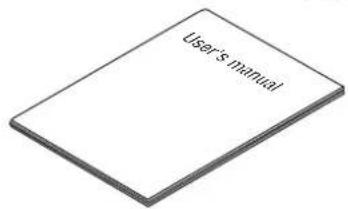
User is manualiP-40 User's Manual

natural_image
Simple geometric shape: a tilted rectangle with no text or symbolsiP Viewer Software Quick Reference*
* Only included with the iP-40SE.

natural_image
Isometric line drawing of a USB connector with terminal ports (no text or symbols)D terminal/RGB conversion cable (IPC-D/VGA)
(Option)

SD memory card (Class2)
(Capacity: 1GB, Model: AV-SDSDC 1GB)
(Option) * Can be used only for IP-40SE only
Names and Functions of the Parts (Projector)
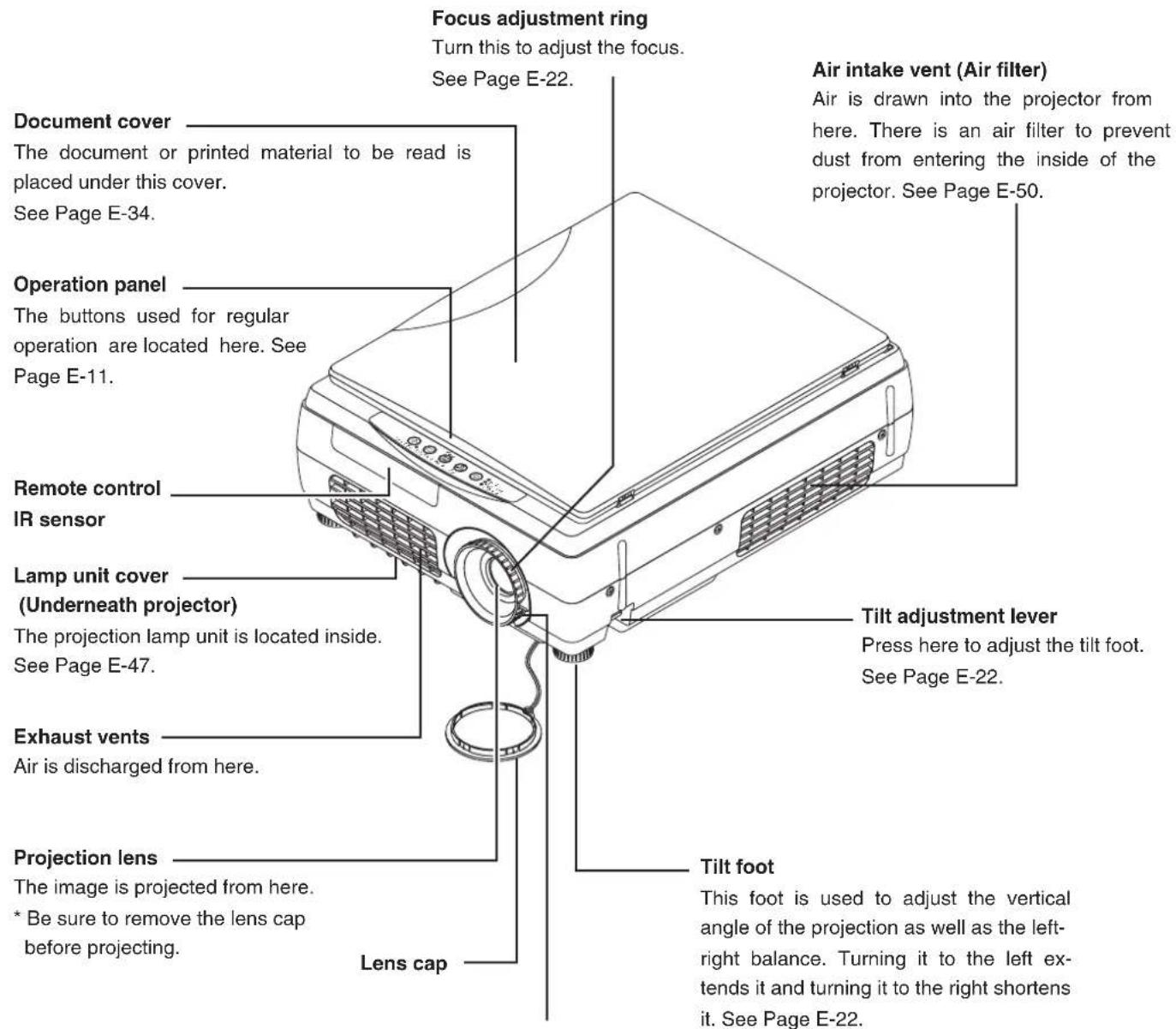
text_image
Focus adjustment ring Turn this to adjust the focus. See Page E-22. Document cover The document or printed material to be read is placed under this cover. See Page E-34. Operation panel The buttons used for regular operation are located here. See Page E-11. Remote control IR sensor Lamp unit cover (Underneath projector) The projection lamp unit is located inside. See Page E-47. Exhaust vents Air is discharged from here. Projection lens The image is projected from here. * Be sure to remove the lens cap before projecting. Lens cap Air intake vent (Air filter) Air is drawn into the projector from here. There is an air filter to prevent dust from entering the inside of the projector. See Page E-50. Tilt adjustment lever Press here to adjust the tilt foot. See Page E-22. Tilt foot This foot is used to adjust the vertical angle of the projection as well as the left-right balance. Turning it to the left extends it and turning it to the right shortens it. See Page E-22.Zoom lever
Turn this to adjust the screen size. See Page E-22.
| CAUTION | ·During unit operation, do not obstruct the front of the lens. During operation, strong light through the lens is projected. Obstruct the front of the lens causes fire or burn.·During projection, be sure to remove the lens cap. Negligence to observe it may deform the lens |

text_image
Document reading area The document or printed material that you wish to project in the OHP mode is placed here. See Page E-34. Input connector panel The connectors for the personal computer, video, and other connections are located here. See Page E-10. Remote control IR sensor Power input connector Plug in the power cable here. See Page E-21. Theft prevention lock Please see the Note below. Speaker (2 W, monaural) HandleNOTE
About the anti-theft lock
The anti-theft lock is compatible with Kensington security cable lock.
Contact the following for more information about the products.
Kensington Computer Products Group
Phone: (650) 572-2700
Fax: (650) 267-2800
URL: http://www.kensington.com
Names and Functions of the Parts (Input Connectors)

text_image
PC IN TESTRGBVLRUSBAUDIOMEMORY VIDEO IN 5 71. Test (maintenance) connector
This special connector is used at the time of maintenance and factory tests. It cannot be used for other connections.
2. Computer/video (D terminal output) video input connector
Use this input terminal for connection to a computer's analog RGB input connector or a video deck's D connector output using an RGB conversion cable (sold separately). See pages E-16 and 20.
3. Video input connector
This input connector is for use with the video (NTSC / PAL / SECAM). See Page E-20.
4. Audio input connectors for the video
Audio input connectors for use with the video. (Stereo supported) See Page E-20.
5. Computer audio input connector
This audio input connector is used for connection to a computer (stereo compatible). See Page E-16.
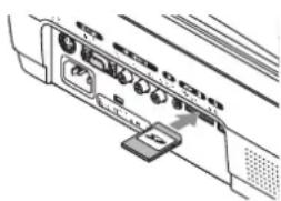
6. SD memory card insertion slot
SD memory card access LED \*
During the SD memory card access, the SD memory card access LED goes on in green.
- When the SD memory card is pulled and inserted immediately, the SD card may not be capable of being recognized. Leave it for several seconds before inserting the SD memory card. - While the access LED of the SD memory card is ON, do not insert or remove the SD memory card.
Negligence to observe it causes the product or SD memory card to fail.
* Only for iP-40SE
7. USB connector\*
This connector is used for USB connections with a personal computer. * iP-40SE only.
NOTE:
The L+R sound is issued from the monaural speaker.
The SD memory card guarantees the operation only for our optional items (model: AV-SDSDC1GB). SD memory card that was checked for operation by our company is explained at our website (http://www.avio.co.jp/english/products/mp/index.htm) The other SD memory cards are not guaranteed to operate.
For how to use the SD memory card, refer to the SD Memory Card Instruction Manual.
Setting and removing the SD memory card
Setting the SD memory card
- Set the title of the SD memory card upwards and insert the SD memory card straightforwardly into the depth of the insertion slot until a "click" sound is issued.
Note that forcibly inserting the SD memory card in a wrong direction may cause the product or the SD memory card to fail or be damaged.
(After the SD icon is displayed on the screen, make operation.)
text_image
CD-ROM 6.019 5Removing the SD memory card
- Pressing the SD memory card until a "click" sound is issued makes the SD memory card come out slightly.
- Slowly pull out the SD memory card straightforwardly.
NOTE:
After changing over to the OHP input, insert or remove the SD memory card.

text_image
Diagram of a device control panel with labeled buttons and an arrow indicating directionNames and Functions of the Parts (Operation Panel)

text_image
ON/STANDBY LAMP/COVER TEMP 1 2 3 4 5 6 7 8 INPUT ROTATION FREEZE OFF FREEZE CAPTURE TRANSFER1. ON/STANDBY LED
Lit red during standby and lit green when the projection lamp is on. See Page E-21.
2. LAMP/COVER LED
Lit green during projection. Lit red when the air filter or lamp unit cover is not in place.
- At the time of the projection lamp lighting operation, the LED flashes for about 6 seconds and then lights green.
- At the time of a projection lamp lighting failure, the LED flashes green. (The flashing interval when the projection lamp is off will be longer than when the LED flashes at other times.)
- When the projection lamp is off, the LED flashes green for 60 seconds and then goes off.
- When the projection lamp has been used in excess of 1,900 hours, the LED flashes red; when use exceeds 2,000 hours the LED is lit a steady red.
See Page E-45.
3. TEMP LED
When the internal temperature has risen excessively, the LED flashes red for 10 seconds, then is lit a steady red. See Page E-45.
LED List
| LED State | Significance | |||
| ON/STANDBY | LAMP/COVER | TEMP | ||
| Off Off Off AC power OFF | Normal condition to | |||
| Red Off Off Standby | ||||
| Green | Flashing green | Off | Standby to start of projection | |
| End of projection standby | ||||
| Green Green Off Projecting | ||||
| Red Red Off | Lamp cover open | Power has been switched OFF because of the alarm | ||
| Lamp burned out | ||||
| Lamp usage exceed 2,000 hours | ||||
| Red Orange Off Internal problem | ||||
| Red Off Red | Temperature fault | |||
| Fan fault | ||||
| Green | Flashing red | Off | Lamp usage exceed 1,900 hours | s Alarm sounding |
| Green Green | Flashing red | Abnormal temperature warning | ||
4. ON/STANDBY Button
Switches the power of the projector on or off (standby mode).
- Only this button is effective when the projection lamp is off. See Page E-21.
5. INPUT Button
Press this to switch the input.
The input switches as follows: OHP→PC→VIDEO or OHP→VIDEO(D4)→VIDEO.
See page E-23.
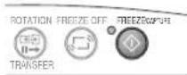
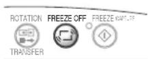
6. ROTATION/TRANSFER Button
At OHP selection: Changes over the direction of the projection screen every 90 degrees (clockwise). The changed-over screen is displayed according to the lateral axis.
See page E-23.
When a USB cable is connected, the images stored in the internal memory are transferred to the computer. (This function is only available on the iP-40SE.)
See pages E-26 and 32.
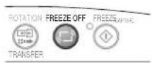
7. FREEZE OFF Button
Cancels the still image mode.
This is used when checking the projection screen while moving the document.
See Page E-27.
8. FREEZE/ CAPTURE Button
Makes the projection screen image into a still image. In the OHP mode, the image is stored in internal memory as a thumbnail.
When the SD memory card has been inserted, the image is saved in the SD memory card. *
* Only for iP-40SE.
See Page E-26.
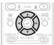
Names and Functions of the Parts (Remote Control)

text_image
ON/STANDBY MUTE 1 3 VOLUME + 4 BRIGHT + 5 ZOOM 7 MENU ROTATION 6 FREEZE OFF FREZE/CAPTURE SET/POINTER 10 INPUT THUMB -NAIL OHP PC VIDEO 12 13 14 151. ON/STANDBY Button
Switches the power of the projector on or off (standby mode).
- Only this button is effective when the projection lamp is off.
See Page E-21.
2. MUTE Button
Temporarily blanks the projection screen without switching off the lamp. One more press causes the screen to return immediately.
See Page E-33.
3. VOLUME Buttons
These buttons adjust the volume when the PC or video is selected.
See Page E-32.
4. BRIGHTNESS Buttons
These buttons adjust the brightness of the projection screen.
See Page E-25.
5. ZOOM Buttons
These buttons adjust the magnification of the projection screen.
See Page E-24.
6. MENU Button
Switches on or off the display of the menu screen.
See Page E-36.
7. SCROLL Buttons
Sets the selection of the item or the adjustment value at the menu screen. Moves the zoom position during a zoom display. Moves the pointer when the pointer is being displayed.
See Pages E-24, 25, 28 and 33.
8. SET/POINTER Button
During menu display, this button advances the menu to the next level. This button finalizes the setting at the time of item selection. See Pages E-33 and 36. This button displays a pointer when the menu screen is not displayed.
Press this button one more time to make the pointer disappear.
9. ROTATION Button
Changes over the direction of the projection screen every 90 degrees (clockwise).
The changed on-screen display appears according to the lateral axis.
See page E-23.
10. FREEZE/ CAPTURE Button
Makes the projection screen image into a still image. In the OHP mode, the image is stored in internal memory as a thumbnail.
When the SD memory card has been inserted, the image is saved in the SD memory card.
* Only for iP-40SE.
See Page E-26.
11. FREEZE OFF Button
Cancels the still image mode.
This is used when checking the projection screen while moving the document.
See Page E-27.
12. OHP Button
Switches the projector to OHP input. See Page E-23.
13. PC Button
Switches the projector to PC input. See Page E-23.
14. VIDEO Button
Switches the projector to video input. See Page E-23.
15. THUMBNAIL Button
Displays the captured still image as a thumbnail.
See Page E-28.
Operation of the Remote Control
- Please use the remote control within a range of about 7 m from the remote control IR sensor of the projector (located at both the front and rear) and within an angle of 10 degrees to the left and 10 degrees to the right. Note that this distance may be shorter depending on battery consumption.
- The remote control will not function when there is an obstacle located between the remote control and the remote control IR sensor of the projector.
Battery Replacement

text_image
Insulation sheetBefore Using the Projector
An insulation sheet has been inserted for protection during transportation prior to shipping. Please pull out and remove the sheet before use.
1 Firmly hold the remote control with your hand and insert the tip of a ballpoint pen or some other pointed object into the hole on the rear side.
Note that there is the risk of scratching the case when using a pointed item such as an awl.
2 Slide the battery holder toward you by pressing from above with the pointed item, then remove the holder.
3 Insert the battery with the + side facing up as illustrated on the inside of the case.
4 Return the battery holder to its original state.

natural_image
Line drawing of a hand holding a small electronic device with a pen inserted (no text or symbols)
natural_image
Line drawing of a hand holding a small object with a pen inserted, no text or symbols present

natural_image
Line drawing of a rectangular electronic component with a small battery inserted (no text or symbols)| ⚠ CAUTION | Handling of the Remote ControlDo not subject the remote control to a strong shock such as dropping it from a table. Doing so could damage it and render it inoperable.Do not expose it to water or other liquid. If the remote control becomes wet, wipe it dry immediately.Avoid exposure to heat and steam. Remove the coin-type lithium battery when the remote control will not be used for an extended period.Do not disassemble or heat the coin-type lithium battery, nor throw it into a fire.Please follow the disposal method of your region in disposing of the used coin-type lithium battery.The remote control may fail to operate or performance may worsen when it is used near an inverter type fluorescent lamp.Please store the coin-type lithium battery in a place that is out of the reach of children. If the battery is swallowed, promptly seek the care of a doctor.Please handle the remote control with care, since there are some operations available only with it. |
NOTE: When it is time to replace the battery, please purchase a CR2025 coin-type lithium battery. The use of batteries having a different shape such as the CR2032 may make removal difficult.
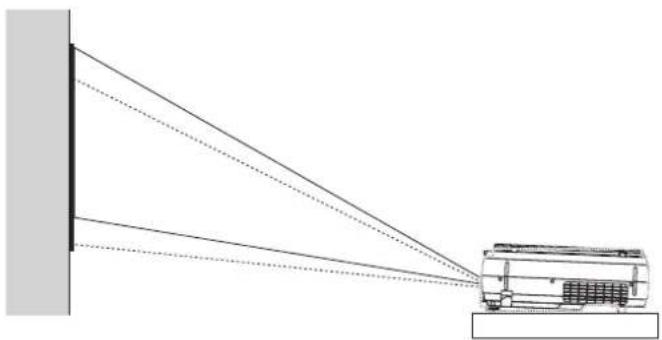
1 Consideration of placement location and screen size
Determine the screen and projector setup location. Set the projector on a strong and stable, level platform.

natural_image
Diagram showing a device emitting beams from a vertical wall, with no text or symbols present.See Page E-15 for information about the projection distance and screen size.
2 Connections with input equipment
Connect your personal computer/video equipment. Connections with the Personal Computer → See Page E-16 Connections with the Video Equipment → See Page E-20
3 Connect the power cable and switch on the power
Switch On the Power → See Page E-21 Switch Off the Power → See Page E-21
4 Switch on the power of the personal computer or video equipment
5 Properly adjust the projection image to the screen
→ See Page E-15
natural_image
Diagram showing light rays projecting off a vehicle against a wall, with no text or symbols present.Perform the tilt adjustment of the projector to provide the desired projection height.
The tilt adjustment allows the position of the projection image to be raised and lowered. The adjustment angle is from 0 degrees to 6 degrees.
Tilt adjustment → See Page E-22
6 Select the input equipment
→ See Page E-23
7 Adjust the image or video
Adjust the image to provide the optimum condition, as required. → See Page E-41 - E-44
Please use the following diagrams to determine the screen display size and the type of screen required for any given projector location.
Projection distances that will be in focus will be 1.3 m (4.3 feet) to 11 m (36 feet) from the front of the lens. Please arrange the setup within this range.

line
| Distance (m) | Wide (inch) | Tele (inch) | |---|---|---| | 6.6 | 40 | 30 | | 8.0 | 60 | 40 | | 10.0 | 80 | 60 | | 13.1 | 100 | 80 | | 15.0 | 150 | 100 | | 26.2 | 200 | 150 | | 32.8 | 250 | 200 | | 39.4 | 300 | 250 |Projection Distance Table
| Projection Distance (m) Screen Size (Inch) | |
| Wide Tele | Diagonal |
| 9.1 250 | |
| 7.3 8.5 200 | |
| 5.5 6.4 150 | |
| 3.7 4.3 100 | |
| 2.6 3.0 70 | |
| 1.5 1.7 40 | |
Wide: The size of the projection image becomes maximum with the projection image size adjustment using the zoom lens
Tele: The size of the projection image becomes minimum with the projection image size adjustment using the zoom lens
| CAUTION | Setup LocationDo not place the projector in locations that will reach high temperatures or low temperatures.Operation ambient temperature: 0°C (32°F) to 35°C (95°F)Set the screen so that it is not exposed to direct sunlight or the light of direct illumination. When light hits the screen, the screen show a white cast and will be difficult to watch.In a bright room, the curtains should be drawn or blinds closed and the area around the screen kept dark.Do not set up the projector in locations exposed to dampness, dust, greasy smoke or tobacco smoke.Doing so will result in the adhesion of dirt to lenses, mirrors, and other optical parts and cause a degradation of image quality.Do not place the projector in a location where the ventilation vents will be blocked or in closed areas having poor ventilation. Doing so will cause the temperature to rise and could cause a fire or accident.(The exhaust vents are at the front of the projector and the air intake vents are located at the side.)Do not place the projector at a location where it may be propped up or swayed.During unit operation, do not obstruct the front of the lens. During operation, strong light is projected through the lens and if the front of the lens is obstructed by a matter or hand, it may cause fire or burn.During projection, be sure to remove the lens cap. The lens cap may be deformed.Please do not set the projector on a table or desk mat made of a heat-sensitive material. Table may be discolored or desk mat may be deformed. |
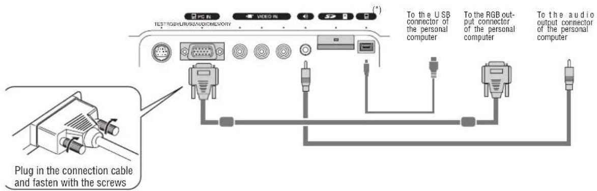
Connections with the Personal Computer
 CAUTION CAUTION | Connection PrecautionsTo protect this projector and the equipment to be connected, switch off the power of each unit before making connections.Please read the various equipment instruction manuals for information about the connection of the equipment and the method of use.When connection is made with a notebook computer and the image is displayed on the LCD screen of the notebook computer, a proper display might not be obtained on projection screen. Switching off the display of the notebook computer will result in a proper display. The method of switching off the display of the notebook computer will differ depending on the PC manufacturer. Please read the instruction manual of the notebook computer for details.Connection might not be possibly depending on the model and settings of the personal computer. Please contact your dealer of purchase for further information. |
Basic Connections
text_image
PC 箱 TESTRGBVLRHSSAUDIOMEMORY VIDEO 箱 S (*) To the USB connector of the personal computer To the RGB output connector of the personal computer To the audio output connector of the personal computer Plug in the connection cable and fasten with the screwsNOTE:
- Input Connectors See Page E-10.
- Please see the "iP Viewer Software Program Operating Instructions" for the method of use when there is a USB cable connection.
* The USB cable and SD memory card can be used only for iP-40SE.
Connections with Personal Computers

text_image
PC connection cable (Supplied item)* Audio cable with mini plugs (Commercially available) * No USB cable is included with the iP-40BE.NOTE:
- After connecting the PC connection cable, set the external output and the computer's screen display settings on the computer.
- When the settings of the external output have not been made, "No signal being input" will be displayed.
- When a condition in which a signal has not been input continues for 15 minutes or longer, the lamp is turned off automatically. (This only functions when the auto power off mode is set to "ON". See page E-44.)
Connecting Macintosh Computers
- When the monitor output is set to the VGA port (mini D-SUB 15-pin), mount the PC connection cable included with the main unit.
- An optional Apple video adapter cable is required when the monitor output is a video port or DVI port.
- Please do not make a USB connection because iP Viewer* does not support the Macintosh.
* The iP Viewer function is only available on the iP-40SE.
Personal Computer Input Connector
Personal Computer Input Connector
The personal computer input connector uses a 15-pin mini D-SUB type connector.
The pins and their corresponding signal inputs are described below.
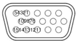
① RED VIDEO
⑥ GND
⑪ NC
② GREEN VIDEO
⑦ GND
⑫ SDA (DDC2B)
③ BLUE VIDEO
⑧ GND
⑬ H.SYNC
④ GND
⑨ NC
⑭ V.SYNC
⑤ NC
⑩ GND
⑮ SCL (DDC2B)
NOTE: The RGB (15-pin) input connector of the projector is of the analog type. This cannot be connected with a digital output type of personal computer.
When the Image of the Personal Computer Screen Is Not Projected
Please check the matters described below when the image of the personal computer is not projected or when there is projection but the image is not correct.
● The image is not projected
When the external output signal from the personal computer is not input to the iP-40, "No computer signal being input" is displayed on the display screen of the iP-40. Should this occur, please check the following matters.
1 Try restarting the personal computer.
When the iP-40 is connected after the personal computer has been started, the connection of the iP-40 might not be recognized by the personal computer. When the iP-40 has not been recognized, the external output signal from the personal computer will not be output and there will not be an image to project.
2 Check the functions of the personal computer.
Depending on the notebook computer, some computers will require an operation to output a signal from the external output connector. If this operation is not performed, the external output signal from the notebook computer will not be output.
Please see the instruction manual of the notebook computer you are using and perform the operation that will output the signal from the external output connector.
(Operation Example)
IBM PC/AT and DOS/V computers:
Press the [Fn] key + "any one of the [F1] to [F12] keys (noting that the operation will differ depending on the model)" PC98 notebook computers later than the Nr Series (with the exception of the PC-98NX):
Press the "Suspend Resume" switch.
Correspondence List for Connection Problems with the Personal
| Manufacturer | External Output Switching Method | Manufacturer | External Output Switching Method |
| IBM Fn+f7 DELL Fn | +f8 | ||
| NEC Parallel output | Toshiba Fn+f5 | ||
| Switching from the Task Bar Panasonic | Fn+f3 | ||
| Fn+f3 Fujitsu Fn+f10 | |||
| COMPAQ Fn+f4 Mitsubishi Fn+f5 | |||
| Sharp Fn+f5 Apple Control panel | →monitor display switching | ||
| SONY Fn+f7 | |||
* This table indicates the results of an independent investigation by us of representative computers made by various manufacturers; it does not include all of the connections.
* Company names and product names mentioned are the trade marks or registered trademarks of the respective companies.
● The screen of the personal computer is correct, but the image is not projected properly
Please check the functions of the personal computer.
Even though the LCD screen of the notebook computer is properly displayed, the projected image might not be projected properly. Due to restrictions of the notebook computer there will rarely be instances in which the setting of a simultaneous display (i.e., simultaneous output of the external output signal while displaying the screen of the personal computer) will result in a signal that greatly deviates from the range supported by the iP-40 and proper projection will not be possible.
Should this occur, a proper image will not be obtained even when adjustments are made with the iP-40.
In some instances, the personal computer screen will be properly projected by the iP-40 when the simultaneous display is cancelled and an operation is performed to output only the external output signal. Please see the instruction manual of the notebook computer you are using for details.
Table of Supported Input Signals
Signals indicated with a "Yes" are supported. Note that depending on the model of personal computer, please perform the screen adjustment of the "Image adjustment" → "Sync adjustment" menu if flickering or bleeding appear on the projection screen. → See Page E-42
| Signal Name | Resolution(Horizontal 2 Vertical) | HorizontalFrequency (KHz) | Vertical Frequency(Hz) | Supported | |
| NTSC RGB -- 15.7 60 No | |||||
| PAL/SECAM RGB -- 15.6 50 No | |||||
| PC-98 Normal*1 | 640 400 | 24.8 56 Yes | |||
| PC-98 Hi 640 400 31.5 70 Yes | |||||
| VGA-GR1 640 480 31.5 60 Yes | |||||
| VGA-GR2*1 | 640 400 | 31.5 70 Yes | |||
| VGA-GR3*1 | 640 350 | 31.5 70 Yes | |||
| VGA-TX1*1 | 720 400 | 31.5 70 Yes | |||
| VGA-TX2*1 | 720 350 | 31.5 70 Yes | |||
| 640×480 72Hz 640 480 37.8 72 Yes | |||||
| 640×480 75Hz | 640 480 | 37.5 75 | Yes | ||
| 640×480 85Hz 640 480 43.2 85 Yes | |||||
| Mac13"RGB 640 480 35.0 66 Yes | |||||
| 800×600 56Hz 800 600 35.1 56 Yes | |||||
| 800×600 60Hz 800 600 37.8 60 Yes | |||||
| 800×600 72Hz | 800 600 | 48.0 | 72 Yes | ||
| 800×600 75Hz 800 600 46.8 75 Yes | |||||
| Mac16"RGB 832 624 49.7 74 Yes | |||||
| 1024×768 43Hz | 1024 | 768 35.5 | 43 No | ||
| 1024×768 60Hz | 1024 | 768 48.3 | 60 Yes | ||
| 1024×768 70Hz | 1024 | 768 56.4 | 70 Yes | ||
| 1024×768 75Hz | 1024 | 768 60.0 | 75 Yes | ||
| 1024×768 85Hz | 1024 | 768 68.7 | 85 Yes | ||
| MAC19"1024×768 | 1024 | 768 60.2 | 75 Yes | ||
| 1280×768 60Hz | 1280 768 | 47.7 | 60 | Yes | |
| MAC21"1152×864 | 1152 | 864 | 68.7 | 75 | Yes*2 |
| 1280×960 60Hz | 1280 | 960 60.0 | 60 | Yes* | 2 |
| 1280×960 85Hz | 1280 | 960 85.9 | 85 No | ||
| 1280×1024 60Hz | 1280 | 1024 | 64.0 | 60 | Yes*2 |
| 1280×1024 75Hz | 1280 | 1024 | 80.0 | 75 | Yes*2 |
| 1280×1024 85Hz | 1280 | 1024 | 91.1 | 85 | Yes*2 |
| 1600×1200 60Hz | 1600 | 1200 | 75.0 | 60 | No |
| 1600×1200 65Hz | 1600 | 1200 | 81.3 | 65 | No |
| 1600×1200 70Hz | 1600 | 1200 | 87.5 70 No | ||
| 1600×1200 75Hz | 1600 | 1200 | 93.8 75 No | ||
| 1600×1200 85Hz | 1600 | 1200 | 106.3 | 85 | No |
- When the resolution of the input signal is lower than 1024 × 768 dots, the image is enlarged and displayed; if the resolution is higher than 1024 × 768 dots, the image is reduced and displayed.
- The signals above marked with (*) may not display properly when full keystone correction is applied. When using these signals and applying keystone correction, please check the image while making the setting so that the image is not adversely affected.
- The zoom function cannot be used for signals marked ( ^* ^2 ) above. To use the zoom function, set the computer's video output setting to WXGA (1280 x 768) or less.
- The signal types of D1 to D4 video (D1:525i (480i), D2-525p (480p), D3:1125i (1080i), D4: 750p (720p) are supported.
The video of a video tape deck or DVD player is projected onto a large screen.
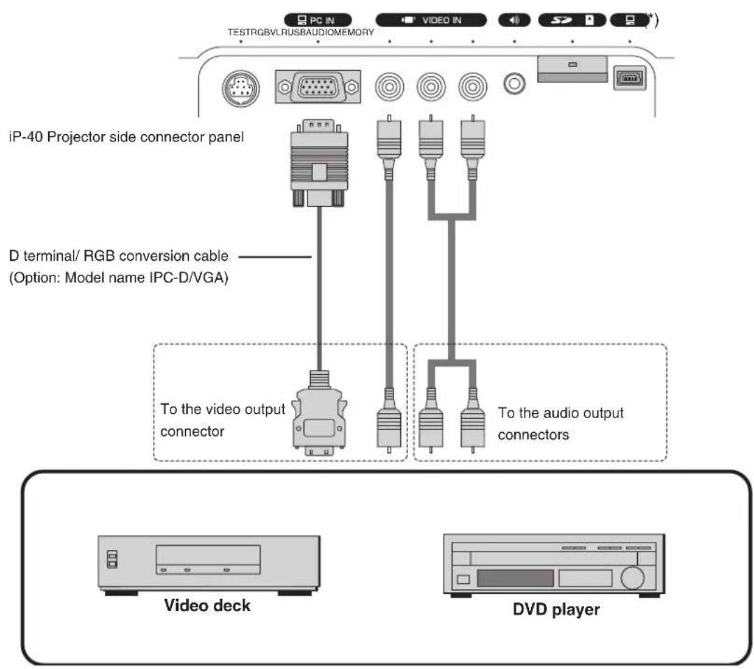
text_image
iP-40 Projector side connector panel D terminal/ RGB conversion cable (Option: Model name IPC-D/VGA) To the video output connector To the audio output connectors Video deck DVD player* The USB terminal and SD memory card can be used only for iP-40SE.
NOTE:
- When a video signal have a lot of noise, the image may be displayed in monochrome. Should this occur, make a setting with the "Video select" menu to suit the input signal.
- When a condition in which a signal has not been input continues for 15 minutes or longer, the lamp is turned off automatically.
(This only functions when the auto power off mode is set to "ON". See page E-44.)
Switch On the Power
1 Connect the power cable
The projector will enter the standby mode and the ON/STANDBY LED will light in red.

text_image
ON/STANDBY LAMPCOVER TEMP INPUT To wall outlet.2 Press the ON/STADNBY button (∅)
Operation with the Projector
Operation with the Remote Control
The fan will turn, the lamp will light, and the ON/STANDBY LED will light in green. The LAMP/COVER LED will light in green.
- If the LED lights in red after the ON/STADNBY button is pressed, projector trouble is indicated.
→ See Page E-51
- Check that the lens cap has been removed before pressing the ON/STADNBY button.
The projector is now able to make a projection.
Switch Off the Power
1 Press and hold the ON/STANDBY button (☐) for 1 second or longer
Operation with the Projector
Operation with the Remote Control
"Press ON/STADNBY button again to turn off" will appear on the projection screen.
2 Press the ON/STANDBY button (one more time.
The lamp will go off.
- The LAMP/COVER LED flashes green, then turns off once cooling is completed.
The ON/STANDBY LED lights in resistance. - When the lamp is off, pressing the ON/STANDBY button while the LAMP/COVER LED is flashing green will not switch the lamp on again.
To switch the lamp on again, please press the ON/STANDBY button again after the ON/STANDBY LED lights in red.
3 Disconnecting the Power Cable
The ON/STANDBY LED on the operation panel will go off.
The power cable can be disconnected even while the lamp/cover LED is flashing green (direct power off function). The fan continues to run for a while to cool the machine.

CAUTION
- With the lamp on and/or with the SD memory card access LED of the SD memory card ON, do not pull out the power cable.
- After using the SD memory card, do not leave the SD memory card inserted and be sure to remove and store it.
- Unplug the power plug of the projector from the wall outlet when the projector will not be used for an extended period.
- When the reinserting the power plug into the outlet soon after having unplugged it, please allow a fixed time (of about 10 seconds) before doing so.
- Wait for the cooling fan to stop turning before stowing away.
Adjusting the Projection Image
Adjust the projection image to the screen.
- When the image is shifted to the left or right, move the projector horizontally.
(Align the center of the screen with the center of the projector lens.)
- When the image is shifted up or down, use the tilt foot to adjust the projector vertically.
- When the image is slanted, turn the left or right tilt foot to adjust.
- When there is keystone distortion of the image, adjust with "Keystone" of the menu operations. When the automatic keystone adjustment mode is set to "ON", however, the image is adjusted automatically. See pages E-37, 38 and 43.
* Depending on the usage environment, it may be necessary to make fine-adjustments manually after automatic keystone adjustment.
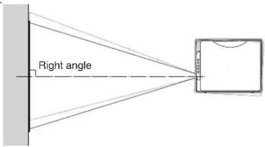
text_image
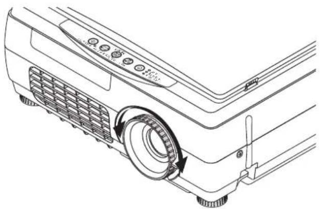
Right angleMaking Focus/Zoom Adjustments
Turn the focus ring/zoom lever of the projection lens and adjust the projection image.
natural_image
Line drawing of a projector rear panel with a circular button and scroll wheel (no text or symbols)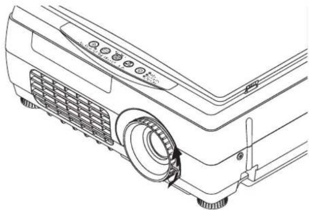
natural_image
Line drawing of a projector with control panel and fan (no text or symbols)The image size depends on the projected distance. See page E-15.
Adjusting the Tilt (Slant)
Adjustment of the tilt foot allows the position and slant of the projection image to be adjusted.
Press the left-right tilt adjustment lever and raise the front of the projector. Release the lever when the desired height has been reached. Rotating the lowest portion of the tilt foot permits fine adjustments to be made.
The tilt foot are lengthened by rotated to the left and shortened by rotated to the right.
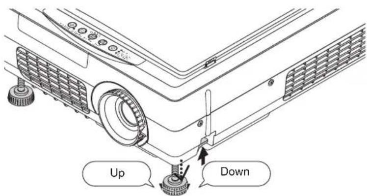
text_image
Up Down
CAUTION
- Do not lengthen the tilt foot on only one side which would place the projector on an extreme slant. Doing so could result in the projector slipping or falling over and could cause an accident or breakdown.
- When moving the projector, be sure to return the tilt foot to the original position.
- The ventilation holes on the projector's sides and bottom take in cooling air using a strong suction force. If cloth or paper get stuck to them, the internal temperature will rise, leading to accidents or damage.
- Depending upon the material of the placement location, the rubber feet may soil on the placement surface.
This section describes the use of direct operation using the projector and remote control buttons.
Please see the items on Page E-32 "Menu Operation Method" and Page E-39 "Menu Description" for information about operation using the menu.
Select the Input
When the projector's power is turned on, one of the input selection icons ([OHP, PC or VIDEO] or [OHP, VIDEO (Component) or VIDEO]) is displayed.
(When the PC input is set to RGB)
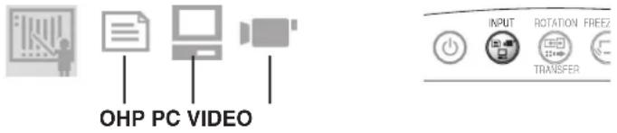
text_image
OHP PC VIDEO INPUT ROTATION FREEZ TRANSFER(When the PC input is set to component)

flowchart
graph TD
    A["OHP"] --> B["D4"]
    C["VIDEO"] --> B["D4"]
    B --> D["INPUT"]
    style A fill:#f9f,stroke:#333
    style C fill:#f9f,stroke:#333
    style D fill:#ccf,stroke:#333
Operation with the Projector
Select the input using the INPUT buttons.
The input switches in the order OHP → PC → VIDEO or OHP → VIDEO (Component) → VIDEO each time the button is pressed.
Operation with the Remote Control
Select the input using the INPUT buttons.
* For instructions on selecting the PC input, see page E-39.
NOTE:
- The input mode at starting time will be the same as it was the last time the projector was switched off.
- When the icon is displayed, either the left or right key permits input switching.
- The color mode icon is displayed at the leftmost end.
- For the color mode, see page E-41, "Image Adjustment."
Color mode icon table
| Standard | Presentation | Natural Blackboard | |
 |  |  |  |
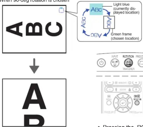
Changing the Orientation of the Projection Image
Effective Only with OHP Input
The direction of the video currently projected is changed over every 90 degrees (clockwise).
The changed video is displayed according to the lateral axis of the screen.
When 90-deg rotation is chosen
flowchart
graph TD
    A["When 30 deg rotation is chosen"] --> B["ABC"]
    B --> C["Green frame (chosen location)"]
    C --> D["Light blue (currently displayed location)"]
    D --> E["ABC"]
    E --> F["ABC"]
    F --> G["ABC"]
    G --> H["ABC"]
    H --> I["ABC"]
    I --> J["ABC"]
    J --> K["ABC"]
    K --> L["ABC"]
    L --> M["ABC"]
    M --> N["ABC"]
    N --> O["ABC"]
    O --> P["ABC"]
    P --> Q["ABC"]
    Q --> R["ABC"]
    R --> S["ABC"]
    S --> T["ABC"]
    T --> U["ABC"]
    U --> V["ABC"]
    V --> W["ABC"]
    W --> X["ABC"]
    X --> Y["ABC"]
    Y --> Z["ABC"]
    Z --> AA["ABC"]
    AA --> AB["ABC"]
    AB --> AC["ABC"]
    AC --> AD["ABC"]
    AD --> AE["ABC"]
    AE --> AF["ABC"]
    AF --> AG["ABC"]
    AG --> AH["ABC"]
    AH --> AI["ABC"]
    AI --> AJ["ABC"]
    AJ --> AK["ABC"]
    AK --> AL["ABC"]
    AL --> AM["ABC"]
    AM --> AN["ABC"]
    AN --> AO["ABC"]
    AO --> AP["ABC"]
    AP --> AQ["ABC"]
    AQ --> AR["ABC"]
    AR --> AS["ABC"]
    AS --> AT["ABC"]
    AT --> AU["ABC"]
    AU --> AV["ABC"]
    AV --> AW["ABC"]
    AW --> AX["ABC"]
    AX --> AY["ABC"]
    AY --> AZ["ABC"]
    AZ --> BA["ABC"]
    BA --> BB["ABC"]
    BB --> BC["ABC"]
    BC --> BD["ABC"]
    BD --> BE["ABC"]
    BE --> BF["ABC"]
    BF --> BG["ABC"]
    BG --> BH["ABC"]
    BH --> BI["ABC"]
    BI --> BJ["ABC"]
    BJ --> BK["ABC"]
    BK --> BL["ABC"]
    BL --> BM["ABC"]
    BM --> BN["ABC"]
    BN --> BO["ABC"]
    BO --> BP["ABC"]
    BP --> BQ["ABC"]
    BQ --> BR["ABC"]
    BR --> BS["ABC"]
    BS --> BT["ABC"]
    BT --> BU["ABC"]
    BU --> BV["ABC"]
    BV --> BW["ABC"]
    BW --> BX["ABC"]
    BX --> BY["ABC"]
    BY --> BZ["ABC"]
    BZ --> CA["ABC"]
    CA --> CB["ABC"]
    CB --> CC["ABC"]
    CC --> CD["ABC"]
    CD --> CE["ABC"]
    CE --> CF["ABC"]
    CF --> CG["ABC"]
    CG --> CH["ABC"]
    CH --> CI["ABC"]
    CI --> CJ["ABC"]
    CJ --> CK["ABC"]
    CK --> CR["ABC"]
    CR --> CS["ABC"]
    CS --> CT["ABC"]
    CT --> CU["ABC"]
    CU --> CV["ABC"]
    CV --> CW["ABC"]
    CW --> CX["ABC"]
    CX --> CY["ABC"]
    CY --> CZ["ABC"]
Operation with the Projector
Press the ROTATION button.
Operation with the Remote Control
Press the ROTATION button.

- Pressing the ROTATION button displays the rotation selection icon. Choose the intended direction. With changeover of the video, the display disappears.
To view the portion that has been cut off

text_image
A B C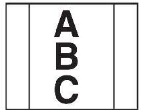
text_image
A B COperation with the Projector
Scrolling is not possible from the main unit's control panel.

text_image
JCOM MENU SUITB FEBRUARY SUPPORTER INPUT DH3 PC VIDEO Video OKOperation with the Remote Control
Press the SCROLL (▲▼) buttons and scroll the projection image up or down.
- Pressing the ZOOM (−) button permits display of a large portion within the reading range of the vertical display. The undisplayed portion can be displayed with the SCROLL (▲▼) buttons.
NOTE: When the orientation of the projection image is changed, even if the zoom function is in use, the display of the switched screen will be adjusted to match the width, the same as with regular changes of orientation.
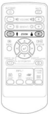
Enlarging and Reducing the Projection Image
This operation enlarges or reduces the size of projected image.
The magnification can be adjusted from none to approximately 25x (length ratio approx. 5x) when the input is set to OHP, 16x (length ratio approx. 4x) when the input is set to PC, or 6.25x (length ratio approx. 2.5x) when the input is set to VIDEO.
At SXGA input, the enlarged display is not available.

flowchart
graph TD
    A["Top Block"] --> B["Down Arrow"]
    B --> C["Single Cube"]
Operation with the Projector
Enlarging/reducing is not possible from the main unit's control panel.
text_image
VOLUME VOLUME VOLUME VOLUME VOLUME VOLUME VOLUME VOLUME VOLUME VOLUME VOLUME VOLUME VOLUME VOLUME VOLUME VOLUME VOLUME VOLUME VOLUME VOLUME VOLUME VOLUME VOLUME VOLUME VOLUME VOLUME VOLUME VOLUME VOLUME VOLUME VOLUME VOLUME VOLUME VOLUME M10000000000000000000000000000000000000000000000000000000000000000000000000000000000000000000000000000 PMPUT GND POT WEDD TICARD-8496Operation with the Remote Control
Press one of the zoom buttons.
i(+): Enlarge the size of the projected image
(−): Reduce the size of the projected image
Moving the Screen
Movement is possible in 4 directions (up, down, left, and right).

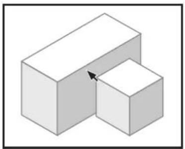
natural_image
Abstract geometric illustration of two stacked 3D cubes with shaded faces (no text or symbols)

natural_image
3D geometric illustration of two cubes with shading, no text or symbols present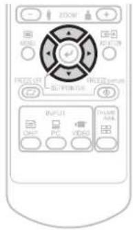
text_image
JISOW R2000 R2000 FROCCUT FROCCUT/RM ELECTRIC/REF INPUT COM PVC VIDEO PHOTO/RM VOUTOperation with the Projector
Scrolling is not possible from the main unit's control panel.
Operation with the Remote Control
Press the SCROLL (▲▼◀▶) buttons.
Adjusting the Brightness
To change the brightness, perform a manual adjustment using the method described below.
Operation with the Projector
The brightness cannot be adjusted from the main unit's control panel.

Brightness adjustment bar
Operation with the Remote Control
Adjust using the BRIGHTNESS (+)/(-) buttons.
(+): Projection image becomes brighter
(-): Projection image becomes darker
NOTE:
- If no operation is performed for several seconds while the brightness adjustment bar is displayed, the brightness adjustment bar turns off.
Capturing the Projection Image
Effective Only with OHP Input
/ Still Image Display
At OHP input
Pressing still FREEZE/ CAPTURE button automatically stores the OHP information into the incorporated memory as the OHP history image.
The image in the incorporated memory is erased by turning off the power.
Operation with the Projector]
Press the still FREEZE/CAPTURE button.
![Elmo iP-40 - Operation with the Projector] - 1](/content/2026/06/1199001/images/0f84100b34a510706f96f97016db2216ad99288bc8728f2fd3df9d69256067a8.jpg)
Operation with the Remote Control
Press the still FREEZE/ CAPTURE button.
NOTE:
- In the case of iP-40SE, when the SD memory card is inserted, the information is recorded precedingly in the SD memory card.
- SD memory card that was checked for operation by our company is explained at our website (http://www.avio.co.jp/english/products/mp/index.htm)
- When the SD memory card is not inserted, the information is saved in the incorporated memory.
- When the write protect switch of the SD memory card is write-disabled, data cannot be recorded.
- In the image file recorded in the SD memory card, you cannot be record a proper date/time.
At image capture, the icon is displayed. The icon display differs depending on the memory capacity currently used.
| Icon Memory capacity | ||
| Incorporated memory storage | Capture of one history image to below 33% of the memory capacity used | |
| 33% to below 66% of the memory capacity used | ||
| More than 66% of the memory capacity used | ||
| Saving disabled | ||
| SD memory card storage * | SD saving | |
| Memory full state | ||
* • The SD memory card can be used only for iP-40SE.
- Our optional item (AV-SDSDC1GB) of the SD memory card can be guaranteed to operate.
- All the SD cards are not guaranteed to operate.
- The SDHC standard SD memory card and high-speed SD memory card (class 6) are not supported.
- When saving a still image just after the SD memory card has been inserted, press the FREEZE/ CAPTURE button after displaying the SD memory card insertion icon.
- Up to 1000 images can be saved in one folder. When saving more than 1000 images, a new folder is created and data is saved in the folder.
- For the saving destination, data is saved in a folder (100 to 499) with a greatest number.
- As the Folder name:xxxAVMPJ (xxx is a number of 100 to 499) / file name: MMPJxxxx (xxxx is a number of 0001 to 1000), 128MB: about 120 images can be saved.
- Back up the SD memory card used for precautionary purposes.
- The initialization (format) of the SD memory card can be performed from on the menu screen (see page E-39.)
- When operating the image file saved in the SD memory card with your PC, use data copied from the SD memory card.

flowchart
graph TD
    A[" "] --> B[" "]
    B --> C["USB"]
    C --> D[" "]
For USB connection
Transferring the image in the incorporated memory makes the saved OHP history image be 0, and data can be saved in the incorporated memory again.
* Only iP-40SE is permitted for USB connection. At USB connection, characters USB are displayed. The number of images that can be saved depends on the image. 50 ordinary images can be saved as the yardstick.
During PC/VIDEO Input
Each time the FREEZE/ CAPTURE button is pressed, the currently projected image will be frozen (in a fixed display).
NOTE:
- The FREEZE LED is lit green during the still image display.
- A press of the FREEZE/ CAPTURE button while a moving image is projected will result in a still image display at the existing zoom magnification and position.
- A press of the FREEZE/ CAPTURE button at the time of still image of OHP will result in a return of the zoom magnification and position to the original condition.
- If the INPUT button on the main unit or the OHP, PC or VIDEO button on the remote control unit is pressed while displaying a still picture, the computer's or video's still picture is canceled and the input changes. In the OHP mode, the still picture remains.
Cancelling the Still Image Display
Operation with the Projector Press the FREEZE OFF button.
Operation with the Remote Control Press the FREEZE OFF button.
Making presentation using the incorporated memory or SD memory card
The history image saved in the incorporated memory or SD memory card * and the presentation image created with iP Viewer are projected with the projector.
Making presentation using the image in the incorporated memory.
1 When the SD memory card has been inserted in the main memory card, remove it \*
The SD memory card takes precedence on the projector. Inserting the SD memory card, the image in the incorporated memory is not projected.
Removing the SD memory card can project the image in the incorporated memory.
* The SD memory card can be used only for iP-40SE.
2 Open the image list
Press the Remote Control's THUMBNAIL button.
The still FREEZE/ CAPTURE of the project goes on in orange (memory output mode).
- Using the menu setting, the number of the images in the list can be set to 4 images or 16 images.
Operation with the Projector
FREEZE/ CAPTURE LED (orange)

text_image
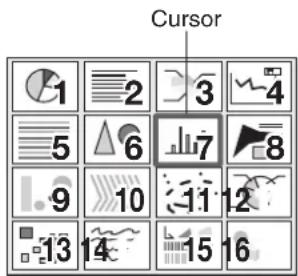
Cursor (red) Reduced image listImage list display

Operation with the Remote Control
NOTE:
The cursor is displayed with the latest image in the list.
Example of 28 images captured and displayed as a list
text_image
17 18 19 20 21 22 23 24 25 26 27 28For explanatory purposes, number 1 to 16 are used to display images.
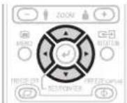
3 Choosing image
Press the remote control's scroll ▲▼◀▶ buttons and move the cursor to the reduced image you want to project.
When the number of reduced images exceeds 16 images, pressing the scroll button changes over to another page.
Operation with the Remote Control
text_image
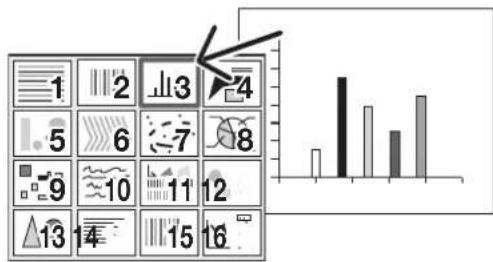
Cursor 1 2 3 4 5 6 7 8 9 10 11 12 13 14 15 164 Full-screen projection
Press the Remote Control's SET/POINTER button.
The reduced image at the cursor position is projected on the full screen of the projector.

bar
| Category | Value | |---|---| | 1 | 0.5 | | 2 | 3.0 | | 3 | 2.0 | | 4 | 2.5 |NOTE:
- The image that was changed over and saved in the vertical direction is projected vertically even when it is displayed laterally in the reduced-size screen.
- This operation is available only by the Remote control.
When feeding the page, choose "Next" (forwards) on the menu.
Operation with the Remote Control
Operation on the screen

text_image
Pointer-Screen History menu Back page in history Next page in history Erase entire history Erase 1 sheet in history5 Choosing the other image
Press the remote control's THUMBNAIL button to return to the image list display.
Start operation with step 3 and choose an intended image.
text_image
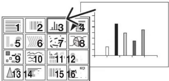
Screenshot of a software interface showing a grid of 16 icons with a bar chart on the right side.
Operation with the Remote Control
6 Projecting/terminating the OHP image
Press the FREEZE OFF button or Remote Control's OHP button and INPUT button of the main unit.
Operation with the Projector
FREEZE/ CAPTURE
LED (light off)

Operation with the Remote Control
Using the SD memory card image to make presentation \*
* Our optional item (model: AV-SDSDC1GB) is guaranteed to operate.
The other SD memory cards are not guaranteed to operate
Depending on the type of the SD memory card, the processing speed may become slower.
The SDHC standard SD memory card and high-speed SD memory card (class6) are not supported.
1 Prepare the material
Set the SD memory card in the main unit. See page E-10
- The SD memory card takes precedence in the projector, and when the SD memory card is set, the image of the incorporated image is not projected.
- The image other than the image captured in the unit and the one saved with iP Viewer or dedicated tool cannot be displayed with the projector.
- For how to prepare material with IP Viewer and dedicated tool, refer to the iP Viewer Instruction Manual. (The dedicated tool can be downloaded from our web site (http://www.avio.co.jp). The dedicated tool registered and saves all the files specified. This tool is best-suited to create material data with a great number of pages such as of a PowerPoint file or JPEG data.)
2 Open the folder list
Press the remote control's THUMBNAIL button.
The FREEZE/ CAPTURE LED of the main unit goes on in orange (memory output mode).
• 16 folders can be displayed at once.

Operation at the main unit
FREEZE/ CAPTURE LED (orange)
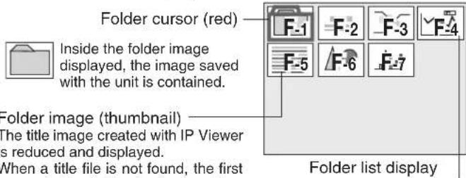
text_image
Folder cursor (red) Inside the folder image displayed, the image saved with the unit is contained. Folder image (thumbnail) The title image created with IP Viewer is reduced and displayed. When a title file is not found, the first Folder list display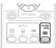
Operation with the Remote Control
Numbers are for explanatory purposes and actually, numbers 1 to 16 are displayed.
3 Choosing a folder
Press the remote control's scroll ▲▼◀▶ buttons to set the folder cursor to the folder image you want to project.
When the number of the folder images exceeds 16, pressing the scroll button changes over to the other page.
Operation with the Remote Control
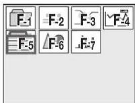
text_image
F-1 F-2 F-3 F-4 F-5 F-6 F-74 Open the file list
Press the remote control's SET/POINTER button to open the file list.
- The image displayed on the folder list is the first one in the file list.

Operation with the Remote Control
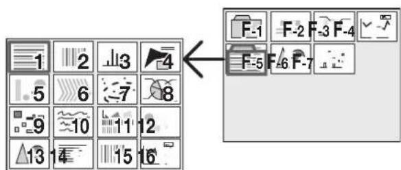
text_image
1 2 3 4 5 6 7 8 9 10 11 12 13 14 15 16 F-1 F-2 F-3 F-4 F-5 F-6 F-7NOTE:
The image that was changed over and saved in the vertical direction is projected vertically even when it is displayed laterally in the reduced-size screen.
5 Choosing a file
Press the remote control's scroll ▲▼◀▶ button and set the cursor to the reduced image you want to project.
When the number of the reduced size screen images exceeds 16, press the scroll ▼ button to display the 17th reduced screen image.
Operation with the Remote Control

text_image
Cursor 1 2 3 4 5 6 7 8 9 10 11 12 13 14 15 16NOTE:
The image file that cannot be played back with the unit is not displayed.
6 Projection on the full screen
Press the SET/POINTER button of the remote control.
The reduced image at the cursor position is projected on the full projection screen of the projector.

bar
| Category | Value | |---|---| | 1 | 2 | | 2 | 5 | | 3 | 4 | | 4 | 3 |When feeding a page, choose the menu "Next."

Operation with the Remote Control
Onscreen operation
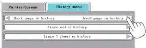
text_image
Pointer-Screen History menu Back page in history Next page in history Erase entire history Erase 1 sheet in historyChoosing the other image
Press the remote control THUMBNAIL button and return to the file list display. To choose another image in the folder, press the Scroll ▲▼◀▶ button.
To return to the folder list, press the THUMBNAIL button again. Start operation with step 3 to choose an intended image.

Operation with the Remote Control
text_image
1 2 3 4 5 6 7 8 9 10 11 12 13 14 15 168 Projecting/terminating the OHP image
Press the remote control FREEZE OFF button or OHP button.
To capture the SD memory card, choose OHP before capturing the image.
For how to capture the SD memory card, see page E-10.
NOTE:
When operating the image data in the SD memory card, handle data copied from the SD memory card.

Operation with the Projector
FREEZE/ CAPTURE
LED (light off)
Operation with the Remote Control
Transferring Captured Images \*
When connection is made with a USB cable, history images can be transferred to the personal computer.

Operation with the Projector
When the input is set to PC/component video: Press the TRANSFER button.
When input set to OHP: Long-press the TRANSFER button.
Operation with the Remote Control
When the input is set to PC/component video: Press the ROTATION button.
When the input is set to OHP: Use the input selector to select PC, then press the ROTATION button.
NOTE:
- Please see the attached "iP Viewer Program Quick Reference" or the "iP Viewer Software Program Operating Instructions" for information about the iP Viewer operation method.
- Once transferred, the images stored in the history are deleted.
- The image cannot be transferred when the SD memory card has been inserted.
* This function is only available on the iP-40SE.
Adjusting the Volume
Effective only During PC and VIDEO Input

Volume adjustment bar
Operation with the Projector
Volume adjustment cannot be made at the operation panel of the projector.

Operation with the Remote Control
Adjust using the VOLUME (+/-) buttons.
NOTE: If no operation is performed for several seconds while the volume adjustment bar is displayed, the volume adjustment bar turns off.
Displaying the Pointer
This operation displays the pointer in the currently projected image.
natural_image
Two 3D rectangular blocks with one larger and one smaller, connected by an arrow (no text or symbols)Operation with the Projector
The ability to turn on and turn off the pointer is not available from the operation panel of the projector.
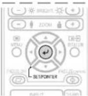
Operation with the Remote Control
Press the SET/POINTER button.
One more press of the SET/POINTER button while the pointer is displayed will turn off the pointer display.
Moving the Pointer
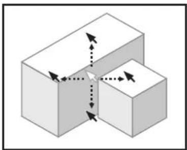
natural_image
3D diagram of two stacked cubes with directional arrows indicating movement or force (no text or symbols)Operation with the Projector
Scrolling is not possible from the main unit's control panel.

Operation with the Remote Control
Press the SCROLL (▲▼◀▶) buttons.
See Page E-35 for information about the form, color, and size of the pointer.
NOTE:
If the brightness is adjusted while the pointer is displayed, the pointer disappears temporarily, but it reappears once the brightness adjustment bar turns off.
During Keystone compensation (trapezoidal compensation), when the pointer is displayed, the pointer color may become striped. It is not a failure.
Deleting the Projection Image and Audio
This operation deletes the currently projected image and audio without switching off the lamp.
Operation with the Projector
The ability to delete the projection image is not available from the operation panel of the projector.
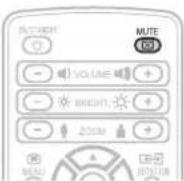
Operation with the Remote Control
Press the MUTE button.
For instructions on setting the mute screen, see page E-35.
NOTE: When a fixed period of time elapses (about 30 minutes) with the video/audio muted, a message will be displayed to check whether to shut down the projector. Selection of "Yes" will set the projector to the standby mode, while a selection of "No" will again delete the video/audio.
When there has been an absence of an operation for 15 seconds during the display of the above confirmation message, the projector automatically enters the standby mode.
Attaching the Document Cover
The mounting orientation of the document cover can be changed to the opposite direction in accordance with the circumstances circumstances.

natural_image
Line drawing of a device with a tray and control panel, no text or symbols presentNOTE: When removing the document cover, lift the cover by both hands and remove it.
Preparation of the Projection Document
The document (printed material) that is to be projected is placed on the projector as illustrated in the diagram below and the document cover is closed.
Horizontal document Top side


Vertical document
Top side
NOTE:
- The document can be projected even when the document cover has not been closed; however, in this instance, unnecessary items may be projected which will make the image difficult to view.
- When shiny paper like magazine covers or black paper is placed on the projector, the internal fluorescent light bulb may be reflected in it, making the edges of the projected document hard to see.
Reading Size of Projection Documents
The maximum reading size of documents and printed material is 216 mm high by 288 mm wide.
Consequently, when A4 paper (210 mm high and 297.5 mm wide) is placed on the projector, reading will be as illustrated in the diagram below (which depicts the area that can be projected as the portion with diagonal lines).
The portion that falls outside of the reading range will not be projected; therefore, shift the paper as required.

text_image
A4 Paper 297 mm (Paper size) 288 mm (Reading size) 216 mm (Reading size) 210 mm (Paper size)Other functions that are used in the OHP operation can be seen on the following pages:
● Switching the input to OHP → See Page E-23
- Changing the projection image to a still image display → See Page E-26
● Capturing a projection image → See Page E-26
- Viewing captured images → See Page E-28
Menu Configuration
The adjustment/setting items and content will differ depending on the input selection and the permitted information will be displayed on the menu for that input mode.
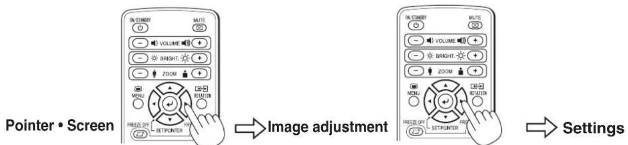
flowchart
graph LR
    A["Pointer • Screen"] --> B["Image adjustment"]
    B --> C["Settings"]
| Pointer • Screen | Image adjustment Settings | |||
| OHP input | Pointer • Screen History menu | |||
| Pointer shape | No. Shhets on thumbnail display (for thumbnail display only) | Red Keystone | ||
| Pointer color | Back page in history Next page in history (in the single sheet display mode) | Blue Language selection | ||
| Pointer size Erase entire history Color mode Projection mode | ||||
| Mute mode Erase 1 sheet in history | Economy mode | |||
| Storage image quality | Auto power off | |||
| SD Format | Lamp usage time | |||
| Input signal | ||||
| PC input (RGB) | Pointer shape Contrast Keystone | |||
| Pointer color Brightness Language selection | ||||
| Pointer size Red Projection mode | ||||
| Mute mode Blue Economy mode | ||||
| Computer input | Sharpness | Auto power off | ||
| Color mode Lamp usage time | ||||
| Sync adjustment | Input signal | |||
| PC input (component) | Pointer shape Contrast Keystone | |||
| Pointer color Brightness Language selection | ||||
| Pointer size Color Projection mode | ||||
| Mute mode Hue Economy mode | ||||
| Computer input | Sharpness | Auto power off | ||
| Color mode Lamp usage time | ||||
| Sync adjustment | Input signal | |||
| VIDEO input | Pointer shape Contrast Keystone | |||
| Pointer color Brightness Language selection | ||||
| Pointer size Color Projection mode | ||||
| Mute mode Hue Economy mode | ||||
| Sharpness | Auto power off | |||
| Color mode Lamp usage time | ||||
| Video select | Input signal | |||
NOTE:
- The document can be projected even when the document cover has not been closed; however, in this instance, unnecessary items may be projected which will make the image difficult to view.
Names and Functions of the Buttons Used in Menu Operation

text_image
ON/STANDBY MUTE VOLUME + BRIGHT. + ZOOM + SET/POINTER Button Used to finalize a setting after making the setting or adjustment. MENU Button Used to display a menu and to close a menu. SCROLL ▲▼◀▶ Buttons Used in the selection of menu names and item names, and to set and adjust item contents.Names and Functions of the Menu Parts

text_image
Menu tab Switches to the various menus when selected. Pointer-Screen Image adjustment Settings Cursor (Light blue) Selects the item that you would like to set or adjust. Contrast 0 Brightness 0 Red 0 Blue 0 Sharpness 1 2 3 4 5 Adjustment bar Indicates the adjustment condi- tion according to the increase or decrease of the bar point. Color Mode Sync adjustment StandardReturns the set or adjusted item to the standard value (shipping default condition of our factory).
Sub menu icon
When an item containing this icon is selected, there is a change to the sub menu.
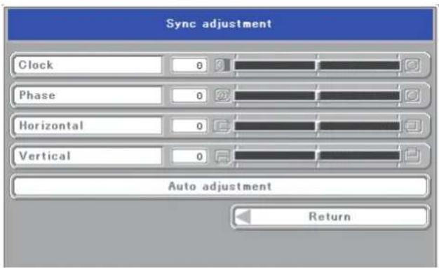
text_image
Sync adjustment Clock 0 Phase 0 Horizontal 0 Vertical 0 Auto adjustment ReturnReturns to the menu that is one layer higher.
Method of Menu Operation
This section describes the actual operation method. Adjustment of [Keystone (Manual)] using the remote control is provided as an example.
1 Press the MENU button and display the menu
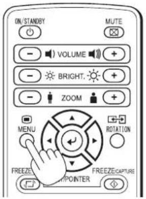
text_image
ON/STANDBY MUTE - VOLUME + - BRIGHT. + - ZOOM + MENU ROTATION FREEZE CAPTURE POWER FROZZECOMPINTER
text_image
Pointer-Screen Image adjustment Settings Pointer shape Pointer color Pointer size Mute screen Black Wallpaper Storage image quality Fine Standard SD format2 Select [Settings] with the SCROLL ◀▶ buttons
![Elmo iP-40 - Select [Settings] with the SCROLL ◀▶ buttons - 1](/content/2026/06/1199001/images/6d8a7724610233f73ee3b58c025ac43c324d2e1f7ca0c1747f9f596b32eada83.jpg)
text_image
ON/STANDBY MUTE - VOLUME + - BRIGHT. + - ZOOM + MENU ROTATION FREEZEOFF FF SET/POINTER![Elmo iP-40 - Select [Settings] with the SCROLL ◀▶ buttons - 2](/content/2026/06/1199001/images/02fccbdaaeeeb82a4e30661a03078a992d701f50eea385bf6ff1b9d55c08b203.jpg)
text_image
Pointer-Screen Image adjustment Settings Keystone Language selection Projection mode Front Rear Economy mode ON OFF Auto power off ON OFF Lamp usage time 0 Input signal PAL 50Hz/3.58MHzEach press of the SCROLL ▶ button switches the menu one step in the sequence of [Pointer • Screen] → [Image adjustment] → [Settings], and each press of the SCROLL ◀ button causes a return in the opposite direction.
3 Select [Keystone] with the SCROLL ▼ button
![Elmo iP-40 - Select [Keystone] with the SCROLL ▼ button - 1](/content/2026/06/1199001/images/55e4d56a478405a47b6e7197540abdf9442f26b9f5d819b009a732aa1f4b6eaa.jpg)
text_image
ON/STANDBY MUTE - VOLUME + - BRIGHT. + - ZOOM + MENU ROTATION FREEZE OFF SET/POINT FREEZE/CAPTUREMove the cursor and select [Keystone].
![Elmo iP-40 - Select [Keystone] with the SCROLL ▼ button - 2](/content/2026/06/1199001/images/2ff79b8b1a4bbf77a042bb117b8701f6bab5e9a3e846ffdf6a206abd9a0a45c4.jpg)
text_image
Pointer-Screen Image adjustment Settings Keystone Language selection Projection mode Front Rear Economy mode ON OFF Auto power off ON OFF Lamp usage time 0 Input signal PAL 50Hz/3.58MHz4 Press the POINTER/SET Button
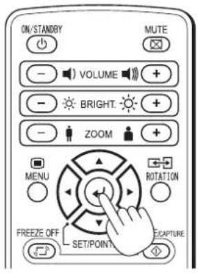
text_image
ON/STANDRY VOLUME BRIGHT. ZOOM MENU ROTATION FREEZE OFF SET/POINT ECAPTURE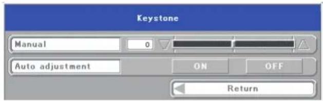
text_image
Keystone Manual 0 Auto adjustment ON OFF ReturnSwitches the menu to the sub menu (i.e., the Keystone adjustment menu).
5 Make the adjustment with the SCROLL ◀▶ buttons while checking the projection image
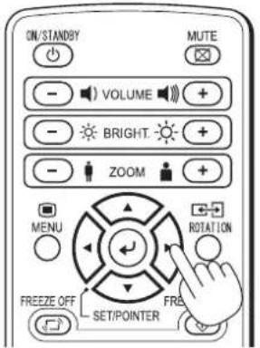
text_image
ON/STANDBY VOLUME BRIGHT ZOOM MENU FROEZE OFF SET/POINTER MUTE ROTATION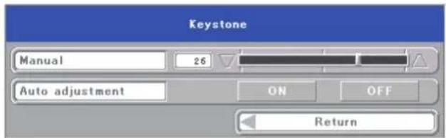
text_image
Keystone Manual 26 Auto adjustment ON OFF ReturnSCROLL ◀ button: Each press causes the numerical value to decrease.
(The lower portion of the projection image becomes narrower.)
SCROLL ▶ button: Each press causes the numerical value to increase.
(The upper portion of the projection image becomes narrower.)
6 Press the MENU button and close the menu

text_image
ON/STANDBY MUTE - VOLUME + - BRIGHT. + - ZOOM + MENU ROTATION FREEZE CAPTURE POWER FREEZE CAPTUREThis completes the [Keystone (Manual)] adjustment.
Pointer • Screen
This selects the shape, color, and size of the pointer.
- Pointer shape ....Selects the shape of the pointer from 2 types.
- Pointer color ....Selects the color of the pointer from amongst 3 types (i.e., red, white, and blue).
- Pointer size ....The size of the pointer can be changed in 3 levels.
● Mute mode ....Sets the image that will be displayed at the time of screen deletion.
Black: Displays an entirely black screen.
Wallpaper: Displays the wallpaper image.
● Storage image quality .....Select the picture quality for saving OHP input only OHP documents in the history.
Fine: When this is selected, the file size is large and fewer images can be stored, but the picture quality is high.
Standard: When this is selected, more images can be stored, but the picture quality is not as good.
SD format ......Execute formatting of the SD mem- OHP input only ory card.
* The format type is FAT16.
NOTE:
When the write protect switch of the SD memory card is disabled, no formatting can be done.
● Computer input ......Select the input signal (RGB or PC input only component video).
RGB: Use this to project images on a computer.
Component*: Use this to project D1 to D4 video images.
* An optional D terminal/RGB conversion cable is required.
* If Component is selected, connect the video's audio to the video audio input terminal.
* When a component is chosen, do not enter the RGB signal (PC video). It is not displayed normally.
During OHP input
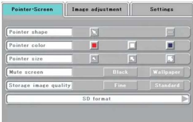
text_image
Pointer-Screen Image adjustment Settings Pointer shape Pointer color Pointer size Mute screen Black Wallpaper Storage image quality Fine Standard SD formatDuring PC/Component video input

text_image
Pointer-Screen Image adjustment Settings Pointer shape Pointer color Pointer size Mute screen Computer input Black Wallpaper RGB ComponentDuring Video input

text_image
Pointer-Screen Image adjustment Settings Pointer shape Pointer color Pointer size Mute screen Black WallpaperHistory menu
OHP input only
● No. sheets on thumbnail
display ....Select the number of thumbnail images to be displayed simultaneously on one screen.
4 sheets: Four thumbnail images are displayed at once.
16 sheets: 16 thumbnail images are displayed at once. (When displaying the SD memory card image, the 16-image display is fixed.)
● Erase entire history ......A confirmation message appears.
Select "Erase all", then press the set/pointer button to delete all the OHP history images stored in the internal memory.
When using the SD memory card, all the data in the folder where currently displayed files are saved is erased.
- Erase 1 sheet in history ...The currently displayed history image is deleted and the next history image is displayed.
When a single image selected from the list of OHP history images is displayed, the following item is also displayed.
● Back page in history Next page in history
Set the cursor then use the ◀ button on the remote control unit to select "Previous history image", the
▶ button to select "Next history image".
Back page in history: The projector switches to the history image stored in the memory before the currently projected history image.
Next page in history: The projector switches to the history image stored in the memory after the currently projected history image.
When a list of history images is displayed
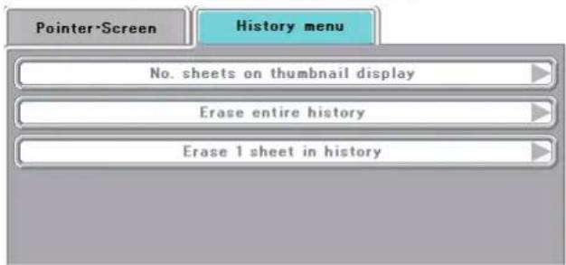
text_image
Pointer-Screen History menu No. sheets on thumbnail display Erase entire history Erase 1 sheet in history
text_image
No. sheets on thumbnail display 4 sheets 16 sheets Return
text_image
Erase entire history Erase all Cancel Return
text_image
Erase 1 sheet in history Erase 1 sheet Cancel ReturnWhen a single history image is displayed
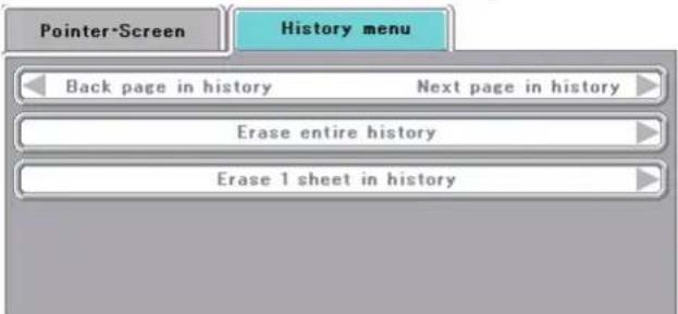
text_image
Pointer-Screen History menu Back page in history Next page in history Erase entire history Erase 1 sheet in historyImage adjustment
This performs the settings and adjustments related to the projected image.
When OHP input has been selected.
Red
(Red color adjustment) ......Adjusts the deepness of the red color in the range of -50 to 50.
Blue
(Blue color adjustment) ......Adjusts the deepness of the blue color in the range of -50 to 50.
During OHP input
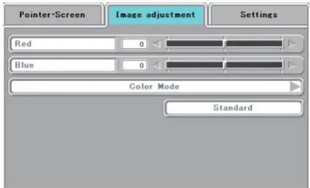
text_image
Pointer-Screen Image adjustment Settings Red 0 Blue 0 Color Mode StandardSub menu: Color mode
● Standard ....The contrast is strong and the image is crisp.
● Presentation ......Displayed in a color suitable for presentation (PC projection).
● Natural ....The images are projected with colors near those of the original image.
● Blackboard ....Use this when projecting images on a blackboard.

text_image
Color Mode Standard Presentation Natural Blackboard ReturnWhen PC input (RGB) has been selected
- Contrast ....Adjusts the contrast of the projected image in the range of -50 to 50.
● Brightness ....Adjusts the brightness of the projected image in the range of -50 to 50.
Red
(Red color adjustment) ......Adjusts the deepness of the red color in the range of -50 to 50.
Blue
(Blue color adjustment) ......Adjusts the deepness of the blue color in the range of -50 to 50.
● Sharpness ......Se le c ts the e sh ar pne ss of the projected image from amongst 5 levels. As the numerical value increases, the sharpness of the image is enhanced.
When the input is set to PC (RGB selected)

text_image
Pointer-Screen Image adjustment Settings Contrast 0 Brightness 0 Red 0 Blue 0 Sharpness 1 2 3 4 5 Color Mode Sync adjustment StandardSub menu: Sync adjustment
- Clock ....Adjusts the horizontal size of the projected image in the range of -50 to 50.
● Phase ....Adjusts the noise/flickering of the projected image in the range of -50 to 50.
● Horizontal ....Adjusts the horizontal position of the projected image in the range of -50 to 50.
● Vertical ....Adjusts the vertical position of the projected image in the range of -50 to 50.
● Auto adjustment ....Performs sync adjustment automatically.
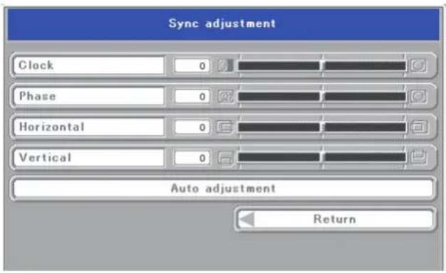
text_image
Sync adjustment Clock 0 Phase 0 Horizontal 0 Vertical 0 Auto adjustment ReturnNOTE: Depending on the PC input signal, there might not be a change as far as from -50 to 50.
When the PC (component) input or the VID-EO input is selected
- Contrast ....Adjusts the contrast of the projected image in the range of -50 to 50.
● Brightness ....Adjusts the brightness of the projected image in the range of -50 to 50.
● Color ....Adjusts the deepness of the color in the range of -50 to 50.
● Hue ....Adjusts the hue in the range of -50 to 50. As the numerical value becomes lower, the color becomes greenish and as the numerical value increases, the color becomes reddish.
● Sharpness ......Selects the sharpness of the projected image from amongst 5 levels. As the numerical value increases, the sharpness of the image is enhanced.
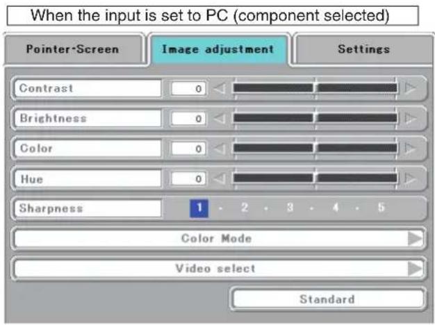
text_image
When the input is set to PC (component selected) Pointer-Screen Image adjustment Settings Contrast 0 Brightness 0 Color 0 Hue 0 Sharpness 1 2 3 4 5 Color Mode Video select StandardSub menu: Video Select (only valid when the input is set to VIDEO)
This selects the input signal system.
Auto (detects the signal system automatically) / NTSC 3.58 / NTSC 4.43 / SECAM / PAL B, G, H, I / PAL M / PAL N
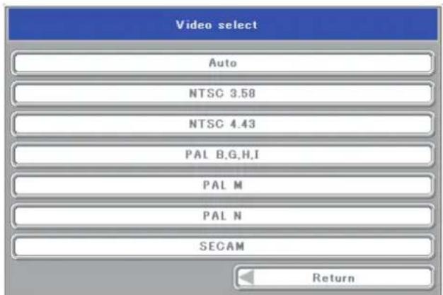
text_image
Video select Auto NTSC 3.58 NTSC 4.43 PAL B,G,H,I PAL M PAL N SECAM ReturnSettings
This performs settings related to the projector unit or while the projector is in use.
● Lamp usage time ......Displays the usage time of the lamp.
"Replacement of the Lamp Unit" → See Page E-47
● Input signal ....The name of the currently selected input is displayed.
Setting Items
● Keystone ....Performs keystone correction of the projection image.
As the numerical value increases, the upper portion of the projection image becomes narrower.
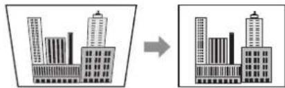
text_image
Diagram showing building transformation from original to simplified model, with Chinese labels indicating structural components.As the numerical value decreases, the lower portion of the projection image becomes narrower.

text_image
Diagram showing transformation of a building with two towers to a single tower, likely illustrating urban or architectural change.When the automatic adjustment mode is set to "ON", the projector's tilt is detected automatically and keystone correction is performed automatically within a range of ± 15^ .
● Language selection ..... Selects from among the following languages the language for use in the menus and message indications: Japanese, English, German, French, Spanish, Italian, Chinese, and Korean.
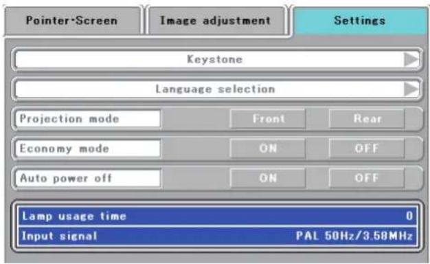
text_image
Pointer-Screen Image adjustment Settings Keystone Language selection Projection mode Front Rear Economy mode ON OFF Auto power off ON OFF Lamp usage time 0 Input signal PAL 50Hz/3.58MHz
text_image
Keystone Manual 0 Auto adjustment ON OFF Return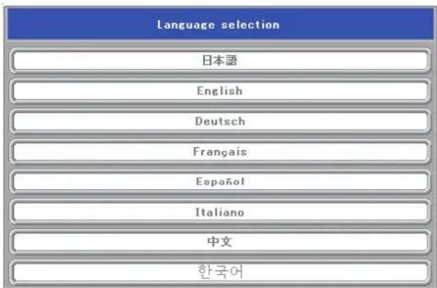
text_image
Language selection 日本語 English Deutsch Français Español Italiano 中文 한국어Continued on the next page
NOTE:
- When keystone correction has been applied, the resolution at the screen edges will degrade and small characters and the like will become difficult to see. When you do not wish to have the resolution degradation, set the projector on a level platform and set the numerical value of the Keystone menu to "0" (no correction).
- Compared to when keystone correction is not applied, the application of keystone correction results in a display image (of characters, etc.) that appears somewhat blurred and this is related to the image processing that is performed.
- The maximum application of keystone correction when a resolution less than VGA resolution (of 640 × 480 dots) is displayed might result in the disappearance of a portion of the image. Please see Page E-19 for details.
- The keystone correction adjustment range will differ depending on the video signal system.
- When the keystone adjustment is performed manually while the automatic adjustment is set to "ON", the adjustment made manually is effective, but the automatic adjustment setting remains "ON".
If the projector is strongly tilted after the adjustment is made manually and the projector is restarted, the adjustment that was made manually is invalidated and the automatic adjustment function becomes effective. If you wish to keep the adjustment made manually, set the automatic adjustment to "OFF" after making the manual adjustment.
● Projection mode ....Selects the projection system of the projector from between Front (front projection) and Rear (rear projection).
● Economy mode ......ON (Economy mode):
The brightness of the lamp will be approximately 80%. The lamp service life will be extended.
OFF (High brightness mode):
The brightness of the lamp will be 100%. There will be a bright screen.
● Auto power off ....When this is set to "ON", the lamp turns off if the projector is in the "No Sync" mode for 15 minutes when the input is set to PC/component video or VIDEO.

text_image
Pointer-Screen Image adjustment Settings Keystone Language selection Projection mode Front Rear Economy mode ON OFF Auto power off ON OFF Lamp usage time 0 Input signal PAL 50Hz/3.58MHzFault Protection
The projector is equipped with a built-in protection circuit to prevent fire and breakdown due to faults.
When the LAMP/COVER LED lights in red
○ Measures to be taken
- Disconnect the power plug from the outlet.
- Properly install the lamp unit cover. See "Replacement of the Lamp Unit" on Page E-47.
When the TEMP LED flashes or lights steadily
○ Measures to be taken
- Disconnect the power plug from the outlet.
- Check the following matters and perform the countermeasure properly.
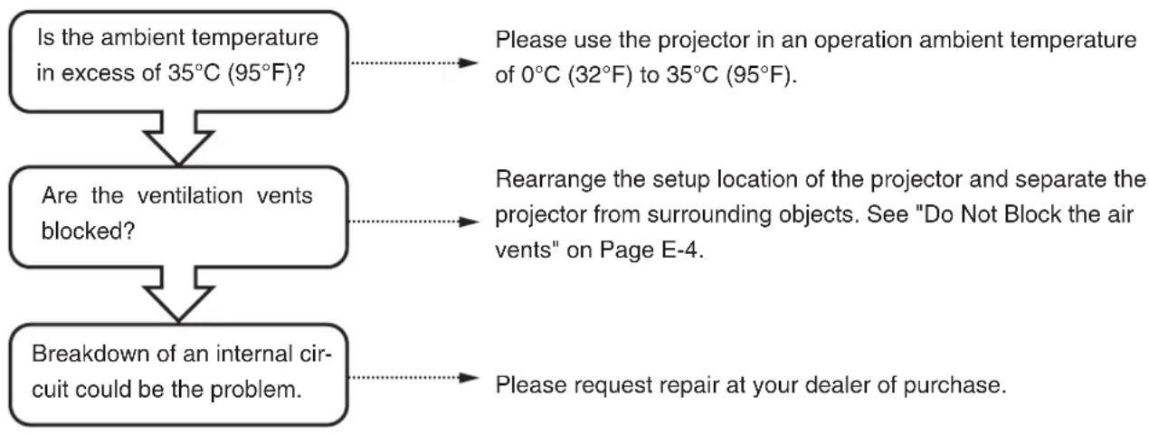
flowchart
graph TD
    A["Is the ambient temperature in excess of 35°C (95°F)?"] --> B["Are the ventilation vents blocked?"]
    B --> C["Breakdown of an internal circuit could be the problem."]
    A -.-> D["Please use the projector in an operation ambient temperature of 0°C (32°F) to 35°C (95°F)."]
    B -.-> E["Rearrange the setup location of the projector and separate the projector from surrounding objects. See "Do Not Block the air vents" on Page E-4."]
    C -.-> F["Please request repair at your dealer of purchase."]
* The projector is running properly when the TEMP LED turn off.
* When the LAMP/COVER LED is lit red at the same time, please replace the lamp. See Page E-47 for information about the replacement method.
* The flashing of the TEMP LED is a warning of a high temperature.
When the usage circumstances have not changed after 10 seconds have elapsed since the start of the flashing, the TEMP LED changes to be lit steady and the lamp goes off.
When the power has failed (When all the LED go off with the power ON)
● Measures to be taken
- Disconnect the power plug from the outlet.
- Check the following matters and perform the countermeasure properly.
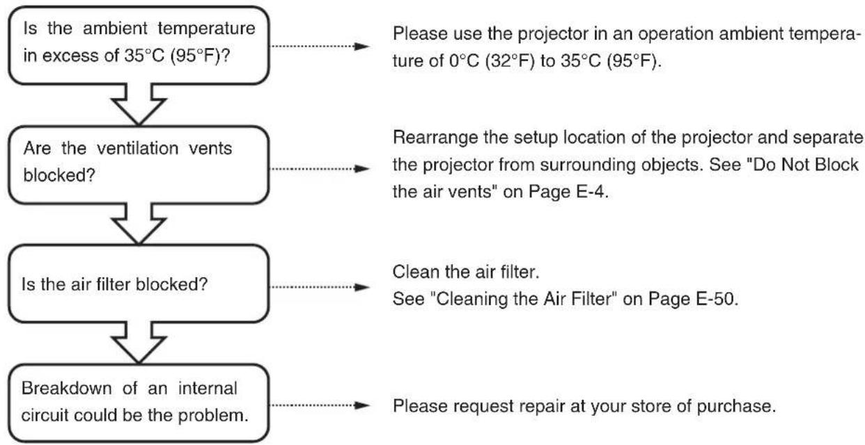
flowchart
graph TD
A["Is the ambient temperature in excess of 35°C (95°F)?"] --> B["Are the ventilation vents blocked?"]
B --> C["Is the air filter blocked?"]
C --> D["Breakdown of an internal circuit could be the problem."]
A -.-> E["Please use the projector in an operation ambient temperature of 0°C (32°F) to 35°C (95°F)."]
B -.-> F["Rearrange the setup location of the projector and separate the projector from surrounding objects. See "Do Not Block the air vents" on Page E-4."]
C -.-> G["Clean the air filter.<br>See "Cleaning the Air Filter" on Page E-50."]
D -.-> H["Please request repair at your store of purchase."]
Replacement of the Lamp Unit
The projection lamp used on this projector should be replaced after about the number of hours indicated below (or sooner, depending on the usage conditions).
When the usage time exceeds 2000 hours*, the possibility for explosion increases, so the lamp is forcibly shut off.
When the usage time exceeds 1900 hours, replace the lamp unit (sold separately) before the usage time reaches 2000 hours.
Also, if the picture is dark, the lamp has reached the end of its service life. Replace it with a new lamp unit.
When the lamp usage time reaches 1900 hours
- Message projected by the projector -
This is displayed when the lamp usage time exceeds 1900 hours.
It is time to replace the lamp.
Replace the lamp.
- Main unit control panel –
The lamp/cover LED flashes red.
The lamp usage time can be checked at the "Installation settings" menu.
When the lamp usage time exceeds 2000 hours
- Message projected by the projector –
The lamp does not light and nothing can be projected.
- Main unit control panel –
The lamp/cover LED lights red.
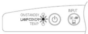
* The lamp usage time indicated on the menu screen is the time calculated by converting the usage times in the high brightness and eco modes to the equivalent in the high brightness mode.
Because of this, if you always use the eco mode, the lamp should be replaced after an actual usage time of between 3900 and 4000 hours, but the approximate time the lamp should be replaced is when the lamp usage time indicated on the menu screen is between 1900 and 2000 hours.

WARNING
- Do not replace the lamp unit immediately after using the projector.
The lamp is high temperature and you could get burned. Disconnect the power plug from the outlet and wait one hour or longer before replacing the lamp. - Do not touch the glass portion of the lamp unit with your hands. Doing so could lower the brightness and shorten the life of the lamp.
- There is a large number of glass parts such as the lamp and mirrors that are used inside the projector. If a glass part breaks, please exercise due caution in handling so that you are not injured by fragments. Please request repair from the store of purchase or an AVIO customer support center.

CAUTION
- Please specify the dedicated lamp unit (Model: IPLK-G1).
Lamp Unit Replacement Procedure
To prevent burns, wait one hour or longer after the lamp has been switched off before performing the following procedure.
1 Remove the lamp unit cover
Using a minus screwdriver, loosen the screws of the lamp unit cover, pull in the direction of the arrow, and remove the cover.
2 Loosen the mounting screws of the lamp unit
Using a minus screwdriver, loosen the 2 screws of the lamp unit.
3 Pull out the lamp unit
Hold the handle of the lamp unit and pull it up and out.
4 Install a new lamp unit
① Take the lamp unit and press it into the projector.
② Check that the two positioning prongs on the bottom of the lamp unit are securely fit into the two holes.
③ Tighten the 2 mounting screws of the lamp unit.
4 Align the 2 tabs located on the lamp unit cover with the projector and attach from the side of the tabs. Tighten the mounting screws of the lamp unit cover.

natural_image
Technical line drawing of a projector with screwdriver and internal components (no text or symbols)
natural_image
Technical line drawing of a projector with internal components and mounting holes (no text or symbols)
natural_image
Technical line drawing of a projector internal structure with no visible text or symbols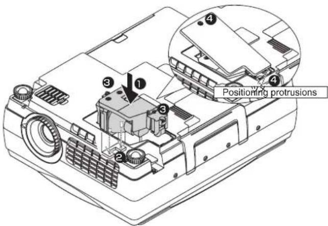
text_image
Positioning protrusions5 Reset the lamp usage time
Please perform the operation indicated below in the standby mode (*).
Operation with the Projector
Press the INPUT, PORTRAIT, FREEZE OFF and FREEZE/ CAPTURE buttons simultaneously, then press the input selector and still picture buttons simultaneously.
Operation with the Remote Control
Resetting of the lamp usage time cannot be performed with the remote control.
The LAMP/COVER LED will flash green following this and projection will start.
* The power plug is plugged into a power outlet and only the ON/STANDBY LED is lit red.

CAUTION
- Do not reset the lamp usage time without replacing the lamp.
The likelihood of the lamp rupturing becomes higher when the lamp has been used in excess of 2000 hours.
6 Check that the indication of the lamp usage time has become "0 H" as illustrated in the diagram to the right.
If the usage time has not been reset, please reset by following Step 5 again.
Check the lamp usage time by pressing the menu button of the remote control to display the menu, then use the scroll
◀▶ button to display the setup setting.
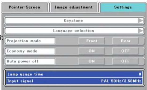
text_image
Pointer-Screen Image adjustment Settings Keystone Language selection Projection mode Front Rear Economy mode ON OFF Auto power off ON OFF Lamp usage time 0 Input signal PAL 50Hz/3.58MHz
CAUTION
If the lamp is used without resetting the usage time, the correct lamp usage time will not be known; therefore, be sure to reset the usage time after lamp replacement. When the indication exceeds 2000 hours, the projector will be forced to turn off the projection lamp.
NOTE:
- In the interest of safety, the lamp will not light when the lamp unit cover is off.
- The lamp units that are available separately are sold together with an air filter as a set in a lamp kit; therefore, please also replace the air filter at the same time as lamp unit replacement. (See Page E-50.)
- Lamp units can be disposed of using the same disposal method as household fluorescent lamps in accordance with the regulations of your region.
Cleaning the Air Filter
The air filter is an important part that prevents the intrusion of dust onto the optical parts and other parts inside the projector. When the air filter becomes blocked, the internal temperature will rise and the rotation of the fan will also increase leading to a reduction of the service life or causing breakdown. In view of this, the air filter should be cleaned regularly (about once a month, when the projector is used 4 hours per day).
Note that the air filter should be replaced with a new one when it becomes difficult to clean out the dust.
Air Filter Cleaning Procedure
1 Pull out the air filter Ⓐ.
2 Remove the air filter cover B.
Press the hooks of the air filter cover B and lift to detach it.
3 Vacuum off the dust.
Use a vacuum cleaner to vacuum off the dust from the front and back of the air filter.
4 Attach.
Follow the removal procedure in opposite order to attach.
- Press the air filter Ⓐ firmly in all the way to the back.
- Press the air filter cover Ⓑ in until a click is heard.
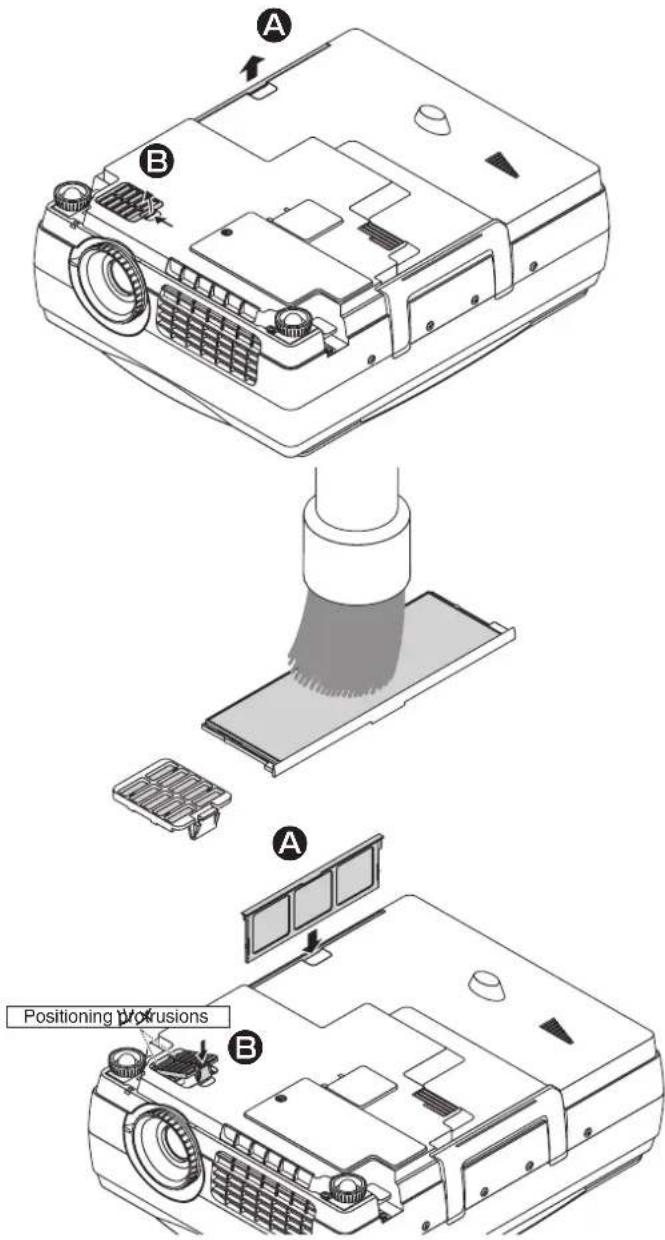
text_image
A B Positioning protrusions A B| CAUTION | Air filter care and precautionsDo not wash with water nor with hot water. Doing so will cause blockage.Do not wipe with a cloth or damp rag. Doing so will cause blockage.Be careful not to forget to install the air filter. Leaving the projector without a filter installed will allow dust to enter the inside of the projector and the image quality may worsen.When the air filter is damaged, be sure to replace it with a new air filter. Use of the projector with a damaged filter will result in dust entering the inside of the projector and this will cause the image quality to worsen. |
NOTE: The air filter can be purchased together with the lamp unit in the separately sold lamp kit (model name IPLK-G1).
When you think the projector may be out of order, please first check the following matters before requesting repair.
| Symptom Please | check this Reference page | |
| Power does not come on • Is the power cable connected? E-21 | ||
| Projection lamp does not light | • Is the lamp burned out?• Is the lamp unit cover installed?• Is the internal temperature high? If so, the lamp will not light to protect the projector from damage.• Is the lamp usage time in excess of 2000 hours? | E-47E-48E-45E-47 |
| There is no image • Has the connected input been selected?• Is the cable of the connected equipment properly connected?• Have "Brightness" and "Contrast" of the "Image adjustment" menu been set all the way to the minus side?• Have you checked the functions of the personal computer? | E-23E-16, 20E-41E-18 | |
| Image is distorted • Is the projector set up properly?• Has keystone correction been applied? | E-14E-43 | |
| Image is blurred • Has the focus been adjusted?• Is the projection distance within the range that can be properly focused?• Has keystone correction been applied?• Is the lens cap attached? | E-22E-15E-43E-8 | |
| The image flickers • Please adjust "Phase" of the "Sync adjustment" menu. E-42 | ||
| The image is out of adjustment | • Are the settings of the "Sync adjustment" menu suitable? | E-42 |
| The color is not right | • Please adjust "Phase" of the "Sync adjustment" menu. | E-42 |
| There is no sound • Is the volume adjustment set to the minimum? E-32 | ||
| There is a snap sound from the cabinet | • This sound is associated with the minute expansion or shrinkage of the cabinet due to a change of the temperature. It has no effect on performance or anything else. | — |
| The remote control will not work | • Is the battery exhausted? Or is it weak?• Is the remote control IR sensor exposed to illumination or other light?• Is the remote control IR sensor blocked?• Is an inverter device located close by? | E-4, 13E-13E-13E-13 |
| At the time of personal computer input selection, the position of the video is shifted, or the display is compressed | • Please adjust using the "Sync adjustment" menu. | E-42 |
| “SD card is not formatted.” Is displayed. | • Have you formatted the card? Format the card with the unit.• Pull out the SD memory card once and after 2 or 3 seconds, try to insert the card again. If the trouble cannot be solved, check the SD memory card. | E-39E-10 |
| The SD memory card cannot be accessed normally. | • Is the SD memory card broken?Check to make sure whether or not it can be used in the other units. (Any SD memory card is not guaranteed to operate.) | — |
| Playback cannot be done from the SD memory card. | • Has the image been saved with the others than the IP Viewer or dedicated tool?• Use the IP Viewer or dedicated tool. | E-30 |
| Display “Error is found during writing” appears. | • Is the SD memory card in protected state?• Reset the write disable (write protected) switch. | — |
| The TEMP LED lights | • Follow the instructions on the "Fault Protection" measures page. | E-45 |
| The LAMP/COVER LED lights in red | • Is the lamp unit cover disengaged?• Is the lamp usage time in excess of 2000 hours? | E-48E-47 |
NOTE:
For the additional information, visit our web site (http://www.avio.co.jp)
LED List
| LED State | Significance | |||
| ON/STANDBY | LAMP/COVER | TEMP | ||
| Off | Off | Off | AC power OFF | Normal condition |
| Red | Off | Off | Standby | |
| Green | Flashing green | Off | Standby to start of projection | |
| End of projection to standby | ||||
| Green | Green | Off | Projecting | |
| Red | Red | Off | Lamp cover open | Power has been switched OFF because of the alarm |
| Lamp burned out | ||||
| Lamp usage exceeds 2,000 hours | ||||
| Red | Orange | Off | Internal problem | |
| Red | Off | Red | Temperature fault | |
| Fan fault | ||||
| Green | Flashing red | Off | Lamp usage exceeds 1,900 hours | Alarmsounding |
| Green | Green | Flashing red | Abnormal temperature warning |
Repair Service Procedure
- Before asking for repair service, check the Troubleshooting section on page E-51 once more. If this check confirms a problem, contact the dealer where you bought the product.
- When asking for repair service, provide your dealer with the following information:
Description of the problem (as many details as possible)
Date of purchase
Your Name
Your Address
Telephone number
Product name and model No. (written on the label at the bottom of the projector)
Notation of the date of production in serial No.
○○○ ○ ○ ○○○○
Month of production
The last digit of year—
1) Month of production: The month of production is represented by A, B, C, ... corresponding to January, February, March, ...
| Month 1 2 3 4 5 6 7 8 9 10 11 12 | |||||||||
| Code A B C D E F G H J K L M |
2) Year of production: The last digit of the year represents the year of production.
| Model Name iP-40SE/iP-40BE | |||
| Type Single-plate DLP ® color wheel color separation type | |||
| Main Part Specification | DLP ® chip | Size 0.7" DLP ® chip x 1, | aspect ratio 4:3 |
| Number of Pixels 786,432 | pixels (1,024 x 768 dots) | ||
| Projection Lens F2.6 to 2.9, f = 25.8 to 30.0 mm, | zoom ratio 1.16 | ||
| Optical Source 200W Super High-pressure Mercury Lamp | |||
| Image Size 33-300 inches diagonal (projection distance 1.3 to 11.3 m) | |||
| Color Reproducibility Full color (16,770,000 colors) | |||
| Brightness 2500 ANSI lumens | |||
| Scan Frequency (analog RGB) Horizontal 24.8 to 68.7 kHz, Vertical 50 to 85 Hz | |||
| Maximum Resolution At RGB signal input 1,024 x 768 dots (Compressed display of 1,280 x 1,024 dots is possible.) | |||
| Video Input | OHP (actual object projection unit) | Scanner | 4.13 million pixel color CCD camera |
| Scanning size | 288 mm x 216 mm (11.3 in x 8.5 in) | ||
| PC (Analog RGB Input) | Signal system | Separate Signal System | |
| Video signal | Analog: 0.7Vp-p/75Ω | ||
| Sync Signal | Separate/composite: TTL Level (positive/negative) Sync on green: 0.3 Vp-p (Negative) | ||
| Terminal Panel | 15 pin Mini D-sub 1 ch | ||
| Video | Signal system | NTSC/PAL/SECAM/PAL-N/PAL-M/NTSC4.43 | |
| Input Terminal | RCA Pin Jack 1 ch | ||
| Component video input *1 | Signal system | Y: Y: 1.0Vp-p/75Ω (with sync), Cb-Cr: 0.7Vp-p/75Ω D1/D2/D3/D4 | |
| Input Terminal | 15-pin Mini D-SUB x 1 | ||
| Audio Input | PC | Audio Signal | 0.4Vrms/47KΩ |
| Input Terminal | Stereo Mini Jack 1 ch | ||
| Video | Audio Signal | 0.4Vrms/47KΩ | |
| Input Terminal | RCA Pin Jack 1 ch | ||
| Video/component video *1 | Audio Signal | 0.4Vrms/47 kΩ | |
| Input Terminal | RCA (L/R) pin-plug jack x 1 | ||
| USB Connector*1 | 1 system USB connector (Mini B type) USB 2.0 | ||
| Scanner output | Exit JPEG (2.272 x 1704 dots) | ||
| Memory interface | SD memory card*4/slot (format: FAT16) | ||
| Audio Output | 2W monaural | ||
| Operating Range of Temperature and Humidity | Temperature: 0 to 35°C (32 to 95°F), humidity: 20 to 80% (no condensation) | ||
| Power Source | 100-120 / 220-240V AC , 50/60 Hz | ||
| Power Consumption | 310W (100-120V AC), 300W (220-240V AC) | ||
| Input Current | 3.1A (100-120V AC), 1.6A (220-240V AC) | ||
| External Dimensions (mm/in) | 290 (W) x 360(D) x 123(H) / 12.2 (W) x 15.9(D) x 5.5(H) (not including protrusions, Including the cover) | ||
| Weight | 5kg / 12.3lbs | ||
| Accessories*2 | Power Cable (3 m/3.3 yd), Remote Control, User's Manual, Battery (Coin-type lithium battery: CR2025), PC cable, Lens cap, iP Viewer Software Quick Reference | ||
| Regulation | Meets FCC Class A requirements Meets EMC Directive (EN55022, EN55024, EN61000-3-2, EN61000-3-3) CE | ||
| Options | D terminal/RGB conversion cable (model name IPC-D/VGA) SD memory card (model: AV-SDSDC1GB) | ||
* USB connectors are not guaranteed to work with all personal computers.
*2 No USB cable is included with the iP-40BE's PC connection cable
*3 The "iP Viewer Software Quick Reference" is not included with the iP-40BE.
* Our optional SD memory card (model: SDSDC1GB) is guaranteed to operate. The other SD memory cards are not guaranteed to operate.
Before initializing (formatting) the SD memory card, be sure to turn off the power. The SD memory card initialized with the other units may not be usable.
When a great number of images have been stored, the saving/playback speed may become slower.
The SDHC standard SD memory card and high-speed 3D memory card (Class 6) are not supported.
- Specifications and designs are subject to change without prior notice in order to improve the product.
The specifications are subject to change without notice.
Viewing the iP Viewer's Operating Instructions
The Intelligent Projector includes a presentation application called “iP Viewer” offering convenient annotation and data storage functions. Use the procedure below to read the operating instructions and be sure to use the projector properly. The USB device driver is loaded in the projector’s memory. The projector must be connected to the computer using a USB cable in order to install the USB device driver* on the computer.
*This is a driver allowing the computer to identify the projector as a large capacity USB removable device. It is installed automatically on the computer when the projector is connected to the computer's USB port.
■ Computer operating conditions
The conditions described below must be satisfied in order for iP Viewer to operate properly.
| Supported OS | Windows XP, Windows Vista (64-bit version excluded)NOTE The operating systems prior to Windows 2000 are out of the operation guarantee range of the iP Viewer. |
| CPU Celeron 800MHz or greater (CPU recommended for Windows Vista) | |
| Memory Windows XP | 256MB or greater, Windows Vista: 1G or greater |
| HD empty space 500MB or more recommended. (drive capacity of the temporary folder) | |
| Display resolution | XGA (1024 x 768 ) or moreNOTE When the resolution is less than the above level, the pointer, etc. of the IP Viewer is not displayed properlyFor how to change the resolution, see the help on your PC. |
| USB port USB 2.0 | |
NOTE
Acrobat Reader (4.15 or newer) must be installed on your computer in order to view the iP Viewer's operating instructions.
Preparations: Before connecting, check that the projector's power is turned off.
1 Connect the computer and projector with the RGB cable.
This connection is not required if you simply want to view the operating instructions. (This connection is for projecting images on the computer.)
2 Turn on the power of both the computer and projector.
3 Connect the projector and computer using the USB cable.
Once connected, installation of the USB device driver starts automatically.
For instructions on connecting see the projector's "User's Manual".
4 Once installation is finished, a message asking you to restart the computer appears. Click the "Restart" button.
This completes USB device driver installation.
5 When the computer is restarted, the "iP-Viewer start?" message appears. Click the "OK" button.
iP Viewer is launched.
If installation does not start automatically
- Installation will not start automatically if the computer's CD-ROM auto start setting is disabled. If this is the case, enable it. (See the computer's help file for instructions on changing the setting.)
- Using Explorer, etc., double-click on the "BootAP.exe" file in the drive called "UD-ROM" (the iP Viewer CD-ROM drive's volume name).
6 Click the "settings" button at the bottom left of the iP Viewer window.
The settings window appears.
7 Click the "manual" button.
The "Language Select" PDF file opens.
Click "English" to open the "iP Viewer Software Program Operating Instructions".
To quit, select "Quit" from the "File" menu on the menu bar.
In Acrobat 6.0, select "Quit Acrobat" from the "Acrobat" menu on the menu bar.
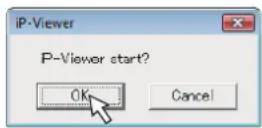


text_image
Version 2.4.5 Temp Directory: C:\Users\KCP\Data\LocalTemp Folder 41 As a default, the content of the environmental variable NT B&S is selected as the "tempBinary directory" that the application uses for work. To change it, please click the "Folder" button and set a directory of your choice. OK CancelNOTE
Be sure to quit iP Viewer and disconnect the USB cable properly, as described in "2-2. Quitting the Program and Disconnecting the USB Device" on page 9 of the PDF file operating instructions.
Power cable for Singapore
