
EDR-10PV - Software Elmo - Free user manual and instructions
Find the device manual for free EDR-10PV Elmo in PDF.

| Product Type | Digital Video Recorder (DVR) Software |
| Model | ELMO-PRO Server (EDR-10PV) |
| Version | v.1.403.16 |
| Minimum Screen Resolution | 1024 x 768 pixels, 32-bit color |
| Maximum Channels | Up to 20: 16 analog + 4 IP cameras |
| Maximum Recording Rate | 240 fps (SPK dependent) |
| Supported Resolutions | 720x480, 720x240, 360x240 |
| Recording Modes | Continuous, Motion, Sensor, Sensor+Motion, Audio |
| Video Compression Quality | 20% (best compression) to 100% (best quality) |
| Display Modes | Mux (multiplexer) and Real-time (30 fps) |
| PTZ Control | Yes, with preset, tour, and pattern support |
| Motion Detection | Up to 5 zones per channel, adjustable sensitivity |
| Search and Playback | By date/time, channel, object search with thumbnail timeline |
| Backup Options | Local storage, CD/DVD, email; AVI or encrypted ELMO format |
| Remote Access | ELMO-PRO Remote software, supports multiple servers |
| User Management | Multi-user with customizable permissions per channel and feature |
| Languages | English, French |
| Watermarking | Always enabled; display option for verification |
| Storage Management | Allocate drives, overwrite or stop when full |
| Compatible Operating System | Embedded Windows OS |
Frequently Asked Questions - EDR-10PV Elmo
User questions about EDR-10PV Elmo
0 question about this device. Answer the ones you know or ask your own.
Ask a new question about this device
Download the instructions for your Software in PDF format for free! Find your manual EDR-10PV - Elmo and take your electronic device back in hand. On this page are published all the documents necessary for the use of your device. EDR-10PV by Elmo.
USER MANUAL EDR-10PV Elmo
ELMO-PRO v.1.403.16 - User Manual
ELMO-PRO v.1.403.16 - User Manual
Copyright ©2007 ELMO USA CORP.
All rights reserved. No part of this manual may be reproduced or transmitted in any form or by any means, electronic or mechanical, including photocopying, recording, or by any information storage or retrieval system, without the prior written permission of the copyright owner and the publisher.
Table of Contents
2.1. ELMO-PRO Remote Setup 137
2.2. Creating a New Connection ...... 138
2.3. Editing an Existing Remote Site Connection 140
2.4. Deleting a Remote Site 141
2.5.Managing Sites 142
2.5.1. Connecting to a Remote Site 142
2.5.2. Activating Connected Servers 142
2.5.3. Disconnecting from a Remote Site 142
2.6. ELMO-PRO Server Setup (via Remote) 143
2.6.1. Remote Info Setup 143
2.7. Viewing Video Channels via Remote 145
2.8. Search on ELMO-PRO Remote 146
2.8.1. Search on the Connected Site 146
2.8.2. Search Offline 148
- Appendix 149
3.1. ELMO-PRO Player 150
3.2. Watermark Tool 151
1
ELMO-PRO Server
Topics Covered
- Introduction
• Starting ELMO-PRO Server - Configuring ELMO-PRO Server
• Search and Playback on ELMO-PRO Server
• Backup on ELMO-PRO Server
1.1. Introduction
1.1.1. Welcome
Thank you for purchasing our ELMO-PRO Series Digital Video Recorder (DVR). ELMO is a register USA CORP.
This manual will guide you through the usage of ELMO DVR Server and ELMO DVR Remote questions or concerns, please visit our website at http://www.elmousa.com or contact our technical
1.1.2. Limited Warranty
ELMO USA CORP. warrants this product to be in compliance with its own plans and specific defects in materials and workmanship under normal use and service for all parts, for a period (1) year after the original purchase date. During this period, ELMO USA CORP. will replace pay
This warranty excludes costs for initial technical adjustments (setup) which are the responsibility of the dealer from whom you purchased the unit. It also excludes damages due to misuse or neglect. Damages resulting from electrostatic discharge (ESD) will not be warranted. This warranty does not cover damages beyond ELMO USA CORP.'s shall ELMO USA CORP. be liable for any direct, indirect or consequential damages, loss of anticipated profits, loss of time or any other losses incurred by the buyer in connection with the purchase, installation, operation or failure of this product. We, ELMO and its agents, are not responsible for viruses. Users should install anti-virus software their own risk. For more details on the limitations of this warranty, contact your distributor.
**For technical assistance, please call: 1-800-947-3566
To obtain service, please follow these steps:
-
Arrange for delivery of your equipment to: ELMO USA CORP., 1478 Old Country Plainview, New York, 11803, USA.
-
All shipments should be shipped prepaid, insured and properly packaged (preferably in the origin accompanied by a letter outlining the defect.
-
Supply your warranty registration, bill of sale, or other evidence of purchase date.

Warning
The ELMO DVR must be used terruptible Power Supply Irated a um of 500 watts, with range Failure to do so will void all
with an Unin- a minim- protection. warranties!
1.1.3. General
This product is the product of ELMO USA CORP. advanced technology and has passed extensive ility tests. Copyright of this manual belongs to ELMO USA CORP., and may not be reprinted written permission. If you need to modify or repair your system, we recommend that you con Dealer/Installer. Otherwise, the system warranty will be voided. Should you have any problems or product, contact your local ELMO Dealer/Installer. This product is certified for domestic and industrial use: TUV certified for Europe, and cULus certified for the USA and Canada.

Warning
This system is running in Embedded Windows OS. Due to the limited flash disk space, installing any additional software on this system is strictly forbidden. Should the additional software be installed on this system, all warranties will be voided.
1.1.4. Precautions
When selecting a storage location for the system, be sure to avoid:
• excessive heat, such as direct sunlight or heating appliances
the moisture, dust, and smoke
• magnetic fields or electrical waves
• temperatures below 5° Celsius or 41° Fahrenheit
• any obstructions to system ventilation holes
Before installing this system, always ensure the:
• power source is located within 3 feet or 1 meter of the UPS
- power is switched off ( ^** Do not plug the DVR unit in.)
• system and its connecting cables have sufficient space
• system is placed on an even surface
- system is situated far from electronic equipment such as microwaves, radios, fridge compressor wireless equipment such as a telephones or cell phones)
- system is at room temperature (18° - 25° Celsius or 64.4° - 77° Fahrenheit)
1.1.5. Unpacking
To unpack the DVR, follow these steps:
- Place the box on a flat, clean surface
- Remove the box by pulling and lifting the system up with both hands
- Place the system down carefully
- Read the User Manual thoroughly before installing the system
- Make sure all the parts listed below have been included:
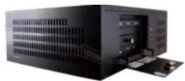
natural_image
Exterior view of a black server rack unit with ventilation slots and drive bays (no visible text or labels)Compact Wallmount model (CW)

Power Cord
Wallmount Bracket
Keyboard
USB Mouse

25 Pin - Video pigtail cable
Before powering up the ELMO-PRO, make sure that the switch in the rear of the DVR is America, 210/220V in other countries.

Warning
An uninterruptible power supply MUST be used; otherwise all warranties will be voided.
- Ground yourself
- Plug in the mouse and keyboard
- Plug in the VGA cable
- Plug in all the BNC connectors
- Plug in the power cable into the UPS (Uninterrupted Power Supply)
• Power up the system

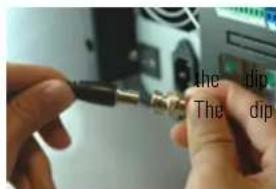
natural_image
Close-up of a hand inserting a cable into a computer monitor (no visible text or labels)Plug the mouse and keyboard into the appropriate ports. The Mouse into the USB Keyboard port is color-coded Purple.
Step 2: Plug the monitor cable into the SVGA connector on the motherboa
After grounding yourself, begin connecting your BNC video cables to the Server's Make sure they are secure and locked into position. Once completed, make sure that switches are in the upward position. This is required in order to test switch terminal is located below the video in/output.

natural_image
Close-up of a hand inserting a USB into a CD drive socket (no visible text or symbols)Connect the power cable to the power supply on your DVR.
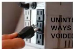
: VERY IMPORTANT! CONNECT THE POWER CABLE 1 (UNINTERRUPTIBLE POWER SUPPLY). PLEASE NOTE: UNINTERRUPTIBLE POWER SUPPLY (MIN. 500VA) MUST ALWAYS BE USED; OTHERWISE ALL WARRANTIES WILL BE VOIDED.
Step 6: The system will power on automatically by default. If this does press and hold the power switch for 2 seconds. The power switch is located DVR (pin hole switch). The system will then power up.
1.1.7. DVR Back View
The following diagram displays the back of the DVR.

1.1.8. Key Features
The following is a list of all new features that can be found in ELMO-Pro Server Version. For a more detailed explanation of features and functionality, refer to the appropriate section in the manual.
-
A channel oriented system design (as opposed to camera system design)
-
Supports three different views: Simple, Advanced and Tree View
-
Supports a total of up to 20 channels, 16 Analog and 4 IP Cameras (true IP cameras of IP cameras is SPK key dependent.
-
Annexus IP modules 101M, 104, and 204 are supported
-
Supports a maximum of 240 fps recording (SPK dependent)
-
In Live mode, Mux Display, the user can search recorded data while viewing live mode cl
-
In Live mode, Real-time Display, the video will be displayed with the real frame rate rega in the Recording/Display setup tab
- Supports the following resolutions: 720x480, 720x240 and 360x240
- Supports Individual Search of recorded data. This allows the user to select a different time for each channel to playback.
- The menu bar allows for easier software navigation
- ELMO Encrypted video player is included with video backup
- Up to 8 Channels of audio supported, on-board audio is also supported
1.1.8.1. Channel oriented system
A Typical DVR system has a camera-oriented system design, where one camera is represented by and every event that happens in the system is associated with the ID of that individual cam
ELMO-PRO has the advantage of using the concept of channels. In a channel-oriented system deented by a virtual data path, which in turn can be associated with any number of any data (video/audio inputs, sensors, controls, PTZ, Text Overlay, and Motion Detection). This approach allows configuration. For example, two channels can record the same analog video input based on different result of this approach, ELMO-PRO users can duplicate the same video input on several channels
1.2. Starting ELMO-PRO Server
The ELMO-PRO Server is an intelligent and innovative software application that offers the user a settings that make one's experience with ELMO DVR effortless and efficient.
Usually the ELMO-PRO Server starts automatically. If it does not, double-click the ELMO Pro Server icon on the

ELMO Pro Desktop. Server

Caution
The ELMO PRO Server only can be started if the screen resolution is 1024x768 pixels and the Color quality is 32bits.

Warning
Note that if the time zone is Windows OS, old video data on Server will be formatted.
changed in the ELMO-PRO
1.2.1. Logging In/Out
After installation, DVR automatically creates an administrative account (elmo). It is recommended to for the administrative account or to create other user accounts. Each user account can be commonly desired cameras and combination of software features are available to the user.
See User Management section for more information.
If the username and/or password are lost, contact the local dealer for information on how to
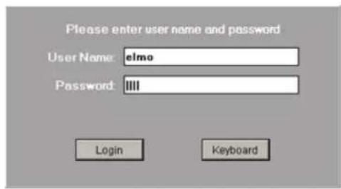
To log into the ELMO-PRO Server, do the following:
- After the ELMO-PRO software loads up, the login window is automatically displayed.
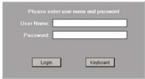
- Enter the User Name and Password. If logging in for the first time, log in as administrator: enter elmo for the User Name and elmo for the Password.
To log out of the ELMO-PRO Server, do the following:
1.
Click the Logout

- A Log Out window will be displayed. To log out, click Yes. Click No to remain logged into the Server.

The system may be configured to automatically log out of the ELMO-PRO Server after a p logout time is set in the User Management setup tab. Please refer to that section for m
Related Topics: User Management
1.2.2. ELMO-PRO Main Screen Features
Main Screen contains the following areas:
- Live Mode
- Search Mode
- Setup Mode
- Screen Divisions
- Full Screen
- Control Center (Tree View) 1. Menu Bar
- Channels/Controls/Sensors Panel - currently active. / available in Simple View
- Advanced Control Panel - PTZ - Not available View
- Advanced Data Manager Panel - Not available i. View
- Storage5. Login/Logout
- Recording Indicator6. Panic
- Current User7. PAC
- Location - configured in Server Info
- Server ID - configured in Server Info
-
Current Date/Time 10. Rotate Channels
-
Current Server mode indicator - currently in Live Mode
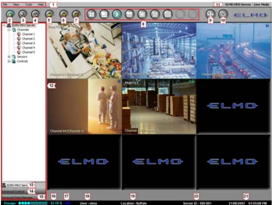

Login/Logout - in order to access the ELMO-PRO Server Setup, search or view the channels or access PACDM™, the user must first log in. To log off, click the Logout button.

Search Mode – displays the ELMO-PRO Server Search mode, which permits channel search and playback, image editing and printing, file backup by time/date/channel, object search, etc. Search mo from the Menu bar. See Menu section for more information.

Setup Mode displays the ELMO-PRO Server Setup menu. Setup mode is also access Menu bar. See Menu section for more information.

Live Mode - displays the ELMO-PRO Server Live mode.

Panic – Panic button acts as an Active Sensor Backup. When Panic is clicked or the sensor is activated, the system will backup 5 prior minutes of encrypted video onto a CD-R. The post-activ is configured by the user in the System Setup menu. See Panic and Sensor Backup ation.

PAC – brings up PACDM™ software for generating reports and POS or Card Access transactions searching.
This button is only displayed if the PACDM™ software is installed and the appropriate Keyl is used.
User : elmo
rrent User - displays the current user logged into the Server.

Recording Indicator - display the status of video recording: recording (blue symbol), not recording (red symbol) or overwriting old data (blue symbol with arrows).

Backup In Progress Indicator - is only displayed when video backup is in pr
Storage: 33.19% displays the percentage of hard disk space used/available for video recording.
For example: the diagram shows that 33.19% of the total allocated disk is used.
01/05/2007 01:18:37 PM date and Time - displays the current date and time. This information is acquired from
the Windows OS. If date/time is not correct, access the Desktop and double time display in the right-hand corner. Set the appropriate time, click Appl the DVR.
Location : Buffalo
Location - displays Server Location specified in Server Information setup
Server ID: 100-001
Server ID - displays the Server ID specified in Server Information setup is required to connect to the Server remotely.
ELMO PRO Server - Live Mode ode indicator distinguishes between Server and Remote software applications and
ELMO PRO Server - Search Mode en "Live", "Search" and "Setup" modes. To switch between the three available
ELMO PRO Server - Setup modes, click corresponding buttons on the main screen. Search and Setup be accessed via menu bar. See Menu section for more information.
1.2.3. Screen Divisions
The Screen Division buttons allows the user to customize the appearance of the main screen. Division is chosen, the corresponding number of channels will be displayed on the Main Screen. using the menu options. See Menu section for more information.

Note
The first available channels will be displayed by default. E.g. If the DVR has 12 conv video inputs and the 9-channel screen division is selected, Channels 1-9 will be displayed on the Main Screen in a 9-channel screen division.
4 4 plays the first 4 available channels in a 4-channel Screen division on the Main Display Screen. Use the mouse scroll wheel to display the next set of channels.
6 6 plays the first 6 available channels in a 6-channel Screen division on the Main Display Screen. Use the mouse scroll wheel to display the next set of channels.
9 9 plays the first 9 available channels in a 9-channel Screen division on the Main Display Screen. Use the mouse scroll wheel to display the next set of channels.
10 10 plays the first 10 available channels in a 10-channel Screen division on the Main Display Screen. Use the mouse scroll wheel to display the next set of channels.
13 13 plays the first 13 available channels in a 13-channel Screen division on the Main Display Screen. Use the mouse scroll wheel to display the next set of channels.
16 plays the first 16 available channels in a 16-channel Screen division on the Main Display Screen. Use the mouse scroll wheel to display the next set of channels.
25 25 plays all available channels in a 25-channel Screen division on the Main Displa

Displays the first 36 available channels in a 36-channel Screen division on the Not available on ELMO-PRO version.

Displays the first 64 available channels in a 64-channel Screen- division on the Not available on ELMO-PRO version.

Full Screen - This button displays the live screen without user interface (no
Click the screen division button to display the screen division panel.
To exit, press the Esc button on the keyboard or select the following icon from the screen division


Rotate Channels - This button continuously rotates channels in the quad scr channel screen division) in a sequence (1-4, 5-8, 9-12, 13-16, etc.). To stop ch the desired Screen Division button or click the Rotate button again to deactivate it.

Note
On the Main Screen, in Mux display, the user can drag-and-drop the channels to any screen division position of their choice.
1.2.4. Menu Bar
The menu bar is one of the new important features that distinguishes the ELMO-PRO. The me system navigation and for quick access to some software features. Four categories are available in the menu bar: File, View, Tools, and Help.
1.2.4.1. File Menu/System Shutdown
The File menu allows the user to shut down the DVR.


Note
This feature is only enabled when is in Live Mode. This feature is Search and Setup modes.
To shut the system down, do the following:
the Server disabled. Select Shutdown in the File menu
- Enter the Password in the Confirm Password window and click OK
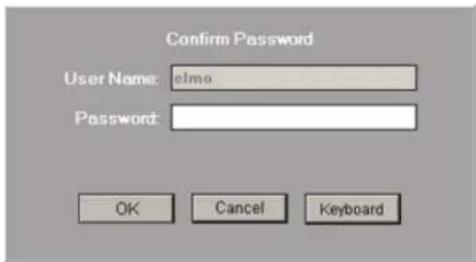
- The following message will be displayed. Click OK to shutdown the system.

1.2.4.2. View Menu
View menu allows switching between three available views: Simple View, Advanced View, and Tr select the Screen Division in the View menu, initiate the Rotate feature or switch between Mu

Default: This feature is only active in the Live Mode (Mux Display). Select Default from the View menu list to display all video channels in their default screen division positions. (i.e. Channel 1 is displayed in the first screen division, Channel 2 is displayed in the 2nd screen division, etc.)
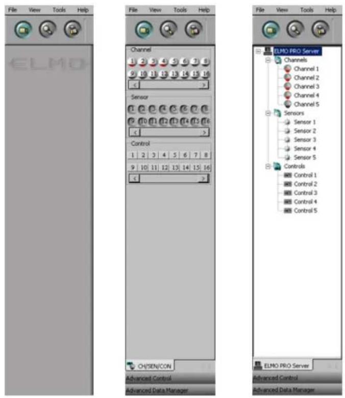
Simple View: The simple view hides the Control Center from the user.
Advanced View: The advanced view shows the Channels/Controls/Sensors, Advanced Control IPTZI and Advanced Data Manager panels. The channels, controls and sensors are represented by buttons.
Tree View: The tree view shows the Channels/Controls/Sensors, Advanced Control (PTZ) and Advanced Data Manager panels. The channels, controls and sensors are shown as icons in a tree structure. The user from the tree view in Control Center to desired screen division position in the Live Mode (M
Compare Simple, Advanced and Tree View displays:
Simple View Advanced View Tree View
Screen Divisions: This feature is only available in the Live Mode. Choose the desired screen division from the list. The screen division can also be changed by clicking the corresponding button on the Main Screen. The screen division list will depend on the unit model.
Live Mode: Select between Mux and Real-time displays.
- Mux Display: displays video on live mode with the frame rate configured in the Recording/Display setup tab. This mode supports drag-and-drop feature, instant search, virtual ruler, text overlay and IP car time Display vs Mux Display section for more information.
- Real-time Display: displays video on live mode with the 30 fps rate regardless of what the user configures in the Recording/Display setup tab. This mode does not support drag-and-drop feature, custom chan instant search, virtual ruler, text overlay or IP camera features. This display mode is beneficial for surveillance purposes. See Real-time Display vs Mux Display section for more information.
1.2.4.3. Tools Menu
Tools menu allows accessing Emap viewer window, setup mode, search mode, backup window, scheduled backup window and virtual keyboard.

Emap Viewer: This feature is only active in the Live Mode (Mux display) and is only enabled when the Emap is configured in the Server setup. See E-Map section for more information. Select Emap Viewer option from the list to display the Emap Viewer window with all configured e-maps.
Setup Mode: Select to access the ELMO-PRO setup mode.
Search Mode: Select to access the ELMO-PRO search mode.
Backup: Select to access the Backup window. See Backup on ELMO-PRO section for more information.
Scheduled Backup: Select to access the Scheduled Backup window. See Scheduled Backup section for more information.
Virtual Keyboard: Select to display the virtual keyboard. The Virtual Keyboard can be used to enter information. Use the mouse cursor to input the alphanumeric characters.

1.2.4.4. Help Menu
Help menu allows accessing the ELMO-PRO user guide, license agreement and ELMO-PRO version.
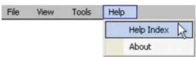
Help Index: Click to display the help menu window.
About: Click to display the ELMO license agreement and the software version. Click I Accept to close.
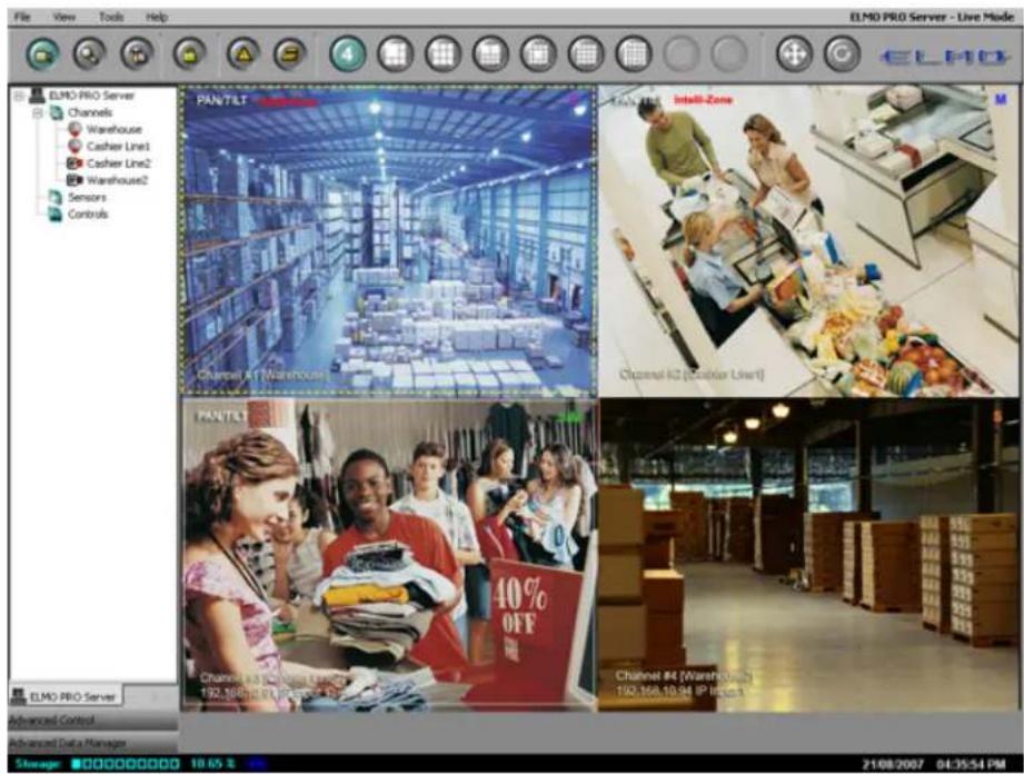
1.2.5. Real-time Display vs Mux Display
ELMO-PRO offers two different Live mode displays: Real-time and Mux (Multiplexer) display.
Real-time display allows viewing analog cameras only. This mode takes raw video directly from the capture card, therefore IP cameras cannot be viewed in Real-time mode. All connected analog video inputs are screen division, the main screen division display cannot be changed in real-time mode. Real-time display does not support text overlay feature or any custom indicators such as PAN/TILT, Intelli-Zone, etc. Additionally, the real-time mode displayed all channels at the 30 frames-per-second rate. Real-time mode is best to be used for monitor time display mode does not reflect the quality of the video recording. I.e. If the Camera 1 is set to 7 fps recording rate, it will still be displayed at 30 fps rate in the Real-time display in Live mode.
Mux (Multiplexer) display allows viewing both analog and IP cameras. Text overlay feature and drag-and-drop features are supported. Each video input can be assigned to one or more channels. Video char on customer preference on the main screen display. Mux mode displays the video recording at recorded (See Recording/Display section for more information). I.e. If the Camera 1 is set to 7 fps recording rate, it will be displayed at 7 fps rate in the Mux display in Live mode.
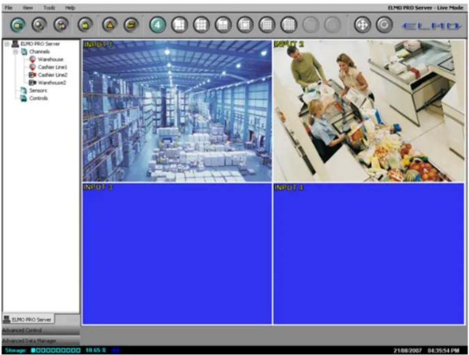
Compare Real-time display and Mux display of Channels 1-4, where Channels 1 and 2 are anal 3 and 4 are IP cameras.
Mux display:
Channels 1-4 are displayed, where Channels 1-2 are analog and Channels 3-4 are IP. Text over

Real-time display:
When the same channels are shown in Real-time display, only Channels 1-2 (analog) can be set text overlay feature is supported. The channels are marked according to the physical video input number in the back of the DVR).
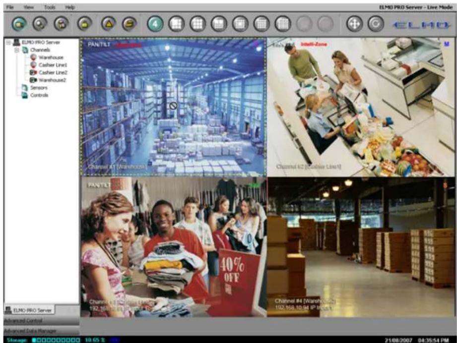
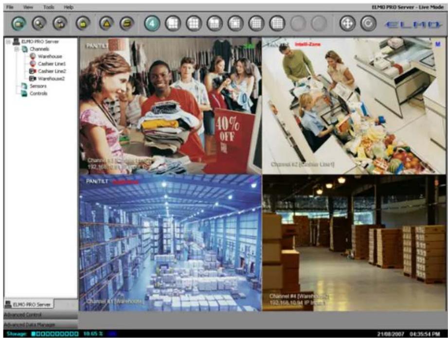
1.2.5.1. Custom Indicators in Mux display
The following custom indicators are available in the Mux display:
- PTZ Camera Indicator. PAN/TILT indicator is only shown for the cameras that have been configured as PTZ cameras in Hardware Setup. Note that the PTZ camera will not respond to user command un
- Intelli-Zone Indicator. Provided the video channel is configured for the Intelli-Zone™ feature, this indicator will be displayed next to the PTZ camera indicator.
- Recording Schedule Indicator. This indicator shows what type of recording the channel is configured for in Schedule Setup.
- Channel #, Name, and IP Address (for IP cameras only). Channel # will remain the same regardless of the location on the main screen. Channel Name is configured in the Hardware Setup.
![PTZ Camera Indicator Intelli-Zone™ Indicator Recording Schedule Indicator PAN/TILT Channel #1 [Warehouse]](/content/2026/06/1226295/images/a8d17937a7146095b11cd25a876abe981f4dc5eb8f1b2199d30006407ed7284f.jpg)
Channel #, Name, (IP Address) Indicator
The following recording schedule indicators are available:
c Continuous Recording
M Motion Recording
s Sensor Recording
S/M Sensor + Motion Recording
C Audio Continuous + Audio Recording
M Audio Motion + Audio Recording
S Audio Sensor + Audio Recording
S/M Audio nsor/Motion + Audio Recording
1.2.5.2. Drag-and-Drop feature on Mux display
Mux display allows the user to drag-and-drop the video channels from the Tree View list direc division.
In order to drag-and-drop the channel onto the main screen division, doing:
-
Ensure that the Tree View is selected from the View menu
-
Select desired screen division by clicking on one of the screen division buttons
-
Expand the Channels list in the Tree View and click on the desired channel to select it
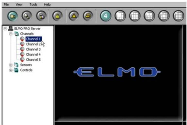
- Hold the left mouse button down and drag the selected channel onto the desired screen
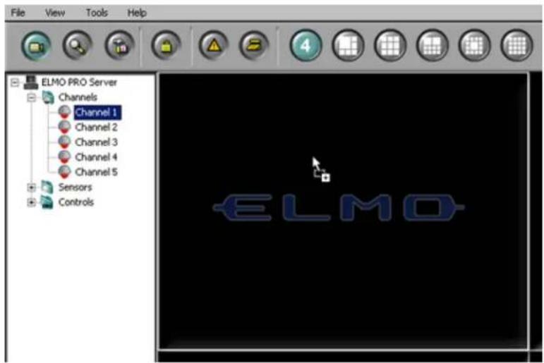
- Release the mouse button. The chosen video channel will be displayed in the selected main
![File View Tools Help ELMO PRO Server Channels Channel 1 Channel 2 Channel 3 Channel 4 Channel 5 Sensors Controls PAN/TILT Channel #1 [Warehouse]](/content/2026/06/1226295/images/e2e3bf8b96cbc6913a89d397b7423f4c5180e6c48ed153055457e0542ede007f.jpg)
In order to move/swap video channel positions on the main screen, do the
- Position the mouse cursor over the desired screen division position and press the left mouse
- Hold the left mouse button and drag the chosen video channel to the new screen division
- Release the mouse button. If the position is empty, the video channel will be moved to position is taken by another video channel, the channels will be swapped. In the example 1 and 3 have been swapped. Note that the Channel number remains the same before and at
1.2.6. PTZ mode
1.2.6.1. Overview
ELMO-PRO software allows controlling the PTZ cameras remotely. Ensure that the correct PTZ Car selected in Hardware Setup. Depending on the camera type chosen, different features are supported must be used for PTZ control.
PTZ cameras can be controlled from:
- ELMO-PRO Server (authorized users only)
- ELMO-PRO Remote (authorized users only)
In the PTZ window the user can:
- Change the pan-tilt settings
- Zoom in and out
- Focus the image
- Configure the presets, preset touring and patterns
The PTZ window can be controlled with:
- The buttons in the PTZ Advanced Control panel
- The Mouse in-cameo function. To do so, click and hold the left mouse button. The user the desired direction and the PTZ camera will follow the mouse cursor.
1.2.6.2. Using the PTZ Mode
In order to use the PTZ mode, make sure the ELMO-PRO software is in with Advanced or section for more information.
To access the PTZ mode, do the following:
- Locate a PTZ channel on the main ELMO-PRO Server window (Live Mode). PAN/TILT text o in the Main Screen. If no PAN/TILT text displayed, the selected camera is either fixed, or in Hardware Setup. Correct PTZ Camera Type and Cam ID must be entered in the Hardwa
- Double-click the video image. Selected channel will be displayed in full screen mode.
-
The PTZ video channel can now be controlled.
-
To control the PTZ channel with PTZ control buttons, click the Advanced Control Panel Center).
- To control the PTZ channel with the in-cameo function, position the mouse cursor within left-click and hold down the mouse button. Move the cursor in the desired direction and the cursor direction.
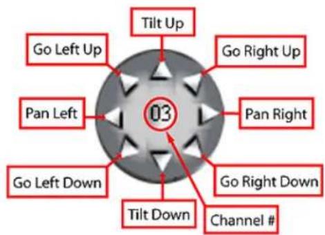
To control the Pan/Tilt position of the camera, follow the diagram below:
PTZ Control Wheel
To control Zoom/Focus/Iris, manage presets/patterns, follow the diagram belc

1.2.6.3. Managing PTZ Presets
Up to 10 different presets can be configured for each PTZ video channel. In order to create camera in the desired direction and then save the preset.
1.2.6.3.1. Programming Presets
To configure the desired preset, do the following:
1. Using PTZ Advanced Controls Panel
- Adjust Pan/Tilt position by clicking the arrows on the PTZ Control Wheel.
- Adjust camera zoom by clicking Zoom In/Zoom out buttons on the panel.
- Adjust camera focus by clicking Focus In/Focus Out buttons on the panel.
- Adjust camera brightness by clicking Iris Close/Iris Open buttons on the panel.
2. Using in-cameo PTZ function
a. Position the mouse cursor within the live view window.
b. Left-click and hold down the mouse button.
c. Move the cursor in the desired direction and the PTZ camera follow the cursor direction
d. Adjust camera zoom by clicking Zoom In/Zoom out buttons on the panel.
e. Adjust camera focus by clicking Focus In/Focus Out buttons on the panel.
f. Adjust camera brightness by clicking Iris Close/Iris Open buttons on the panel.
1.2.6.3.2. Saving Presets
To save the configured preset, do the following:
- In the Advanced Control panel, right-click inside the Presets field
- Select Create Preset from the context menu
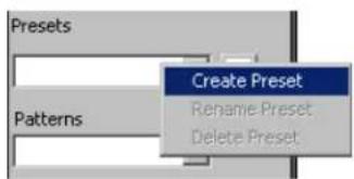
i
Tip
A default name is used for all new presets. The preset(s) can be optionally renamed by the user.
1.2.6.3.3. Renaming Presets
To rename the configured preset(s), do the following:
- Select the desired preset in the Presets drop-down menu
- Right-click inside the Presets field
- Select Rename Preset from the context menu
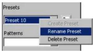
- Type the custom preset name in the Presets field. In the example below, Preset 10 will be renamed.
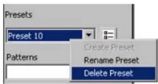
1.2.6.3.4. Deleting Presets
To delete the configured preset(s), do the following:
-
Select the preset in the Presets drop-down menu
-
Right-click inside the Presets field
-
Select Delete from the context menu. In the example below, Preset 10 will be deleted.
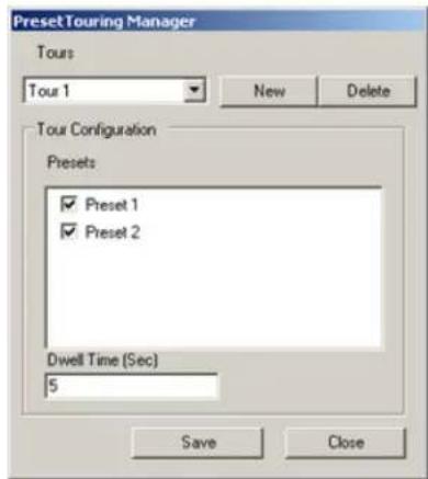
1.2.6.4. Programming Preset Tour(s)
Preset Tour is a sequence of selected presets that is displayed continuously until interrupted by determines the delay time between two consecutive presets.
To create a preset tour, do the following:
-
Program all desired presets in the PTZ mode. (See Managing PTZ Presets for more informa
-
Click the Preset Touring button . The Preset Touring Manager window will be displayed
-
Click New to create a new tour
-
Select the desired presets in the Tour Configuration area by checking off the corresponding
-
Enter the Dwell Time (Sec) value to determine the delay time between two consecutive presets. In the example above, the Preset Tour 1 will cause the PTZ camera to switch between Preset 1 and Pr
-
Click Save to save configured preset tour
-
To create additional Preset Tours, repeat steps 3-6
To stop touring, do the following:
-
Click the Preset Touring button . The Preset Touring Manager window will be displayed
-
In the Tours drop-down menu select the empty position
-
Click Close. The touring will stop.
To delete a preset tour, do the following:
-
In the Preset Touring Manager window, select the Tour from the Tours drop-down menu.
-
Click Delete to delete the unwanted Preset Tour from the list.
1.2.6.5. Programming Pattern(s)
Pattern is a custom path of the speed dome from start point to end point and back. This touring, where camera switches between the maximum of 10 configured presets. Pattern records the speed dome, therefore, the user must be precise, when creating a new pattern to avoid movements.
To create speed dome pattern, do the following:
-
Enter PTZ mode by double-clicking the PTZ channel on the main screen
-
Make sure that the software is in either Advanced or Tree view. To check, click View
-
Click the Advanced Control panel in the Control Center to expand it
-
Configure the pattern start point same as preset via PTZ Advanced Control panel and/or in- (See Programming Presets for more information)
-
Right-click inside the Patterns field
-
Select Create Pattern -> Set Pattern Start from the context menu. The pattern start point has been saved.

-
Create a custom speed dome path that covers all desired locations. Remember that Pattern every move from the time Set Pattern Start has been clicked.
-
When finished, right-click inside the Patterns field
-
Select Create Pattern -> Set Pattern End to complete the Pattern recording
-
The following message will be displayed:
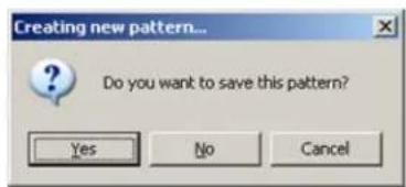
- To save created pattern, click Yes
A default name is used for all new patterns. The pattern(s) can be optionally renamed by
To rename created pattern, do the following:
- Select the desired pattern in the Patterns drop-down menu
- Right-click inside the Patterns field
- Select Rename Pattern from the context menu
- Type the custom preset name in the Patterns field
To delete created pattern, do the following:
- Select the pattern in the Patterns drop-down menu
- Right-click inside the Patterns field
- Select Delete Pattern from the context menu
1.2.6.6. AUX Control Mode
ELMO-PRO supports AUX (Auxiliary) mode for the certain PTZ cameras. This function allows change camera settings remotely through the software, as opposed to adjusting settings manually on the
To access the AUX Control mode, do the following:
- Locate the channel number in the middle of the PTZ Control Wheel
- Right-click the channel number. The context menu will be displayed.
- Select Aux Control from the context menu. Ptz-Aux Control window will be displayed.

The Ptz-Aux Control window displays the list of available auxiliary commands along with the command description. Choose the desired command in the Command drop-down menu and click Execute to apply.
The following auxiliary commands may be available:
- Brightness
- Change ID
-
Color Mode
-
F-OSD
- Load Preset
- Mirror
- Reset
- Set Power
- Set Preset
- Sharpness
- Zoom
1.3. Configuring ELMO-PRO Server
ELMO-PRO Server Setup. Save and Help buttons. Virtual Keyboard.
Every ELMO-PRO Setup tab has Save, Help and Virtual Keyboard buttons:
Click the Save button before closing the Setup window or accessing a different Setup tab in order to save any changes made. Unless the Save button is clicked, all changes will be discarded once Setup Mode is closed. It is enough to click the Save button once in any setup tab in order to save ALL changes made in all setup
Click the Help button to read the Help Manual.
Click the Virtual Keyboard button for user input. The On-Screen Keyboard window will be displayed. Use the mouse cursor to enter desired alphanumeric characters.
![On-Screen Keyboard File Keyboard Settings Help esc F1 F2 F3 F4 F5 F6 F7 F8 F9 F10 F11 F12 psc alk bk * 1 2 3 4 5 6 7 8 9 0 - = bksp ins hw pug nk / * - tab q w e r t y u i o p [ ] \ del end pdn 7 8 9 + lock a s d f g h i k l : * ont 4 5 6 sht z x c v b n m . / sht ↑ 1 2 3 ctd alt alt ctd ← → 0 . eni](/content/2026/06/1226295/images/e4aa9d2a5dec5ffa15c75e7482c7a1cb3286e04eaf11299df34f787c38a4d29c.jpg)
1.3.1. Hardware Setup - Channel Settings
1.3.1.1. Overview
Channel Settings allows:
- Assigning a name to each selected channel
- Associating selected channels with a video source (analog or IP camera)
- Associating selected channels with an audio source
- Modifying the video recording compression quality
- Choosing the PTZ camera type
- Activating the Auto Pan feature for selected channels
- Configuring the Dwell time for a PTZ Auto Pan feature for selected channels

Tip
Only one video source can be assigned to each channel. Each video source can be assigned to multiple channels (duplicated).

Important
Only the administrator user, elmo, can modify this setup tab.
1.3.1.2. Creating/Modifying Channel Settings
Channel Settings
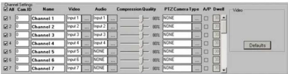
To setup all connected video sources, do the following:
- Check the All checkbox to enable all channels OR enable desired channels by checking individual channel check boxes.
- In the Video field, click the Browse button to display all available video sources connected to the DVR. The input number corresponds the number of physical BNC connector in the back of the DVR.
- In the Audio field, click the Browse button to display all available audio inputs. If audio card is not installed on the DVR, on-board audio can be used. Select desired audio input to be used with the Please see Audio Recording in Search Mode section for information on playing back the audi
- Assign Cam. ID number to any channel that has been assigned a PT/Z camera video source. Cam. IDs help to distinguish between the different PT/Z cameras connected to the same parallel connection. Most their Cam. ID assigned by dip-switches in the back of the camera. Cam. ID must match Source. If the Cam ID has been entered incorrectly, the PT/Z camera will not respond to
The PTZ cameras are controlled based on the entered Cam ID. For example, if the Cam Input 2 in the Hardware Setup, Input 1 will be controlled if the user attempts to control Control Panel. - Assign a descriptive Name to each channel. For example, the channel could be named based on the video source location (e.g. Front Door).
- Adjust video Compression Quality. The lower the number, the higher the compression (20% - best compression, 100% - best quality).
- Choose the correct PTZ Camera Type for all connected PTZ video sources. Click the Browse button to see the list of supported protocols. If the wrong protocol is selected, the camera may not resp
- Check the A/P (Auto-Pan) checkbox for the installed Speed Domes. This feature allows the speed dome to return to the programmed auto pan after the PTZ settings have been adjusted remotely.

Important
Fixed cameras do not have a Cam.

Tip
The BNC connector number does to match the Cam. ID number.
Cam.
-
Assign Dwell time for the A/P setting. This is the time that will pass before the Auto-Pan (A/P) feature will be activated. In the above example, Channel 1 will return to the original pan after 30 seconds.
-
Click Defaults to assign default video source to each channel. By default, video sources (cameras) 1-16 will be assigned to channels 1-16 in a sequence. All configured IP cameras (if any) will be assigned no IP cameras have been configured, channels 17-24 will be assigned no video source.
-
Click the Save button to save the configured settings
Related Topics: PTZ mode | Hardware Setup-Sensor Settings | External Monitor | Motion Setup | Schedule Setup | Video Setup | User Management Setup
1.3.2. Hardware Setup - Control Settings

1.3.2.1. Overview
Control Settings are applicable only if controls are available and are being used.
Active Time
Active Time refers to the designated time when the control is active (is on). The default setting is 0:00:00-0:00:00, which means the control is always off. The control will be continuously on, if the Active Time is set to 0:00:00 - 24:00:00. During the Active Time, the control cannot be turned off from the main screen. Outside of the Active Time, the control can be activated by sensor, or manually from the main screen (Advanced/Tree
Working Sec
Working Sec is the time the control will stay turned on after being triggered by sensor. This control is turned on manually from the main screen. In other words, if the control is turned screen, it will stay on until manually disabled by the user. Working Sec also does not apply during the Active Time, when the Control is continuously on.
1.3.2.2. Creating/Modifying Control Settings

To configure available controls, do the following:
-
Check the All checkbox to enable all controls or enable desired controls by checking individual control check boxes
-
Give each control a descriptive Name. E.g. "Turn on the light".
- Set the Active Time for each control if required. In the above example, Control 2 (Turn on the light) is continuously on between 8:30AM and 5:00PM.
- Enter the Working Sec time for the control. In the above example, Control 2 (Turn on the light) will stay on for 10 seconds if the associated sensor is triggered outside of the Active Time.
5.
Click the Save button to save the configured settings
Related Topics: Hardware Setup-Sensor Settings | Motion Setup | System Setup | Video Set
1.3.3. Hardware Setup - Sensor Settings

1.3.3.1. Overview
In the Sensor Settings the user can configure the connected sensors. Sensors are set as NC NO = Normally Open).
A NC sensor is any sensor with an electrical circuit closed by default.
E.g. - a sensor on a closed door. When the door is opened, the electrical circuit is broken
A NO sensor is any sensor with an electrical circuit open by default.
E.g. - the light in a refrigerator. The light is off by default. When the refrigerator door is opened the circuit is closed and thus the sensor is triggered and the light goes on.
1.3.3.2. Creating/Modifying Sensor Settings
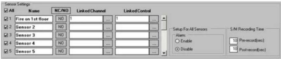
To configure the available sensors, do the following:
- Check the All checkbox to enable all sensors or enable desired sensors by checking individual sensor check boxes
- Assign a descriptive Name to each sensor. For example, the sensor could be named based on the sensor function or trigger (e.g. "Fire on 1st floor").

Caution
Schedule Setup must be properly for sensor recording.
-
Click the NC/NO to set the sensors to NC (Normal Closed) or NO (Normal Open) depending on the type of the sensor
-
Assign a Linked Channel to the desired sensors. Click the Browse button to select the desired channel from the list. If the specific sensor is triggered, the selected channel will begin recording. In the above example, if Sensor 1 is triggered, Channel 1 (Front Door) will start recording.
-
Assign a Linked Control to the desired sensors. Click the Browse button to select the desired control from the list. If a specific sensor is triggered outside of the Control Active Time, the selected control is activated. In the above example, if Sensor 1 is triggered, Control 1 (Open the door) will be activated.
-
Choose Enable to have the alarm sound every time the sensor is triggered OR
Choose Disable to disable the alarm
- Set the S/M Recording Time. The DVR will record for the number of seconds specified prior to and after the sensor is triggered or the motion is detected. In this example, the video channel(s) will record for sensor activation or motion detection and for 10 seconds after the sensor activation or after The pre- and post-record length cannot exceed 10 seconds.
8.
Click the Save button to save the configured settings

Caution
Motion and Schedule Setups must erly configured for sensor and/or recording.
Related Topics: Hardware Setup-Channel Settings | Hardware Setup-Control Settings | Schedule Setup | Communication Setup | Server Info | System Setup | Email Setup | Video Setup
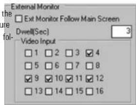
1.3.4. Hardware Setup - External Monitor S

Important
Only Administrator User, elmo, has permission to configure this setup.

Tip
Hardware Setup tab can be hidden from all other users in User Management setup tab.
1.3.4.1. Overview
The External Monitor section allows the user to view selected video inputs on an external monitor (if available). The external monitor should be connected to the DVR I/O Board. Video inputs will be displayed one-t a configured delay time.
1.3.4.2. Creating or Modifying External Monitor Setti
Before configuring this section, make sure that the external monitor is properly connected to the

Important
External monitor must be connected to I/O board. When connected to the ca board, the external monitor will always low the Live mode main screen.
To Set up an External Monitor, do the following
-
Select the video source input number to be shown in the sequence. This refers to the back of the DVR. (i.e. the Video Source in the Channel Settings setup). In this example, in sequence on the external monitor.
-
Specify the Dwell(Sec) time for the sequence. Dwell|Sec| refers to the interval (in seconds) between the display of each video input. In this example, each video input will be shown on the external mo
3.
Click the Save button to save the configured settings
OR
- Check Main Screen Ext Monitor Follow Main Screen to associate the external monitor with the
2.
Click the Save button to save the configured settings
If Ext Monitor Follow Main Screen is unchecked, the external monitor will display selected video source input one by one in sequence. Each video source input will be displayed for Dwell time configured in the External Monitor setup. In this example, cameras 4, 9-12 will be shown in sequence on the external monitor. shown for 3 seconds.
If Ext Monitor Follow Main Screen is checked, the configured video source input sequence will be ignored. The External monitor will display the video source input currently in full screen mode on the by the user or in response to the detected motion. The external monitor will display the last video source input until the next video input is displayed in the Full Screen mode on the ELMO-PRO Server.
Related Topics: Hardware Setup-Channel Settings
1.3.5. Motion Setup
1.3.5.1. Overview
Motion Setup allows for the configuration of motion detection zones for each channel. Each targ motion detection configuration.

Caution
Unless Motion recording is set in the Schedule Setup, the channel will not record and motion will not be detected even if Motion detection target zones are configured for this channel.

Important
This feature is not supported with IP as.
![Motion Current Channel Channel # 1 ... Area Clear Area Draw All Channels Settings Color Of All Motion Areas On Live Mode Green Red Display Motion Area On Live Mode Area Clear Area Draw Area No. 1 Sensitivity Low High Alarm 7 H 30 M - 20 H 20 M Control 2 [Time] 0 H 0 M 5 S Full Screen Settings Enable Full Screen Full Screen Channel 1 Dwell Time 5 Sec Rotate Screen Dwell Time 5 Sec](/content/2026/06/1226295/images/75d46c13f84d154cd1b0d5a36c66feae99cda385a0c91c82aef31d3e77e3c769.jpg)
1.3.5.2. Setting up a target zone for motion detect
![Area No.1 Sensitivity Low High ✓ Alarm 7 H 30 M - 20 H 20 M ✓ Control 2 [Time] 0 H 0 M 5 S Full Screen Settings ✓ Enable Full Screen Full Screen Channel 1 Dwell Time 5 Sec](/content/2026/06/1226295/images/df5237f5803934f6efa4614fc84da8fe8b2f5190f379aeff4ed463a82aa8af93.jpg)
To set up a target zone for a specific channel, do the following:
-
Select the Channel # in the Current Channel frame. Click the Browse button to select the desired channel from the list, selected channel will be displayed in the live view window.
-
Draw the motion detection zone on the selected channel.
-
Place the cursor at the starting point on the live view screen
- Hold down the left mouse button and drag to draw a rectangular area. Adjust the ar
- Repeat steps 1-2 to configure up to 5 (five) motion detection areas.
OR

Note
The area settings are configured for each motion detection area.
- Click Area Draw to set the entire channel screen for motion detection. Click Area Clear to reset all motion detection zones on a specified channel
- Select the desired motion detection area on the live view screen to activate the area set highlighted in red. If the entire channel screen is configured for motion detection, click inside the live view screen to activate area settings.
- Set the Sensitivity for the selected motion detection zone. The higher the Sensitivity, the less change in an image is needed to set off the alarm. If the Sensitivity is set to Low, the change in an image detected as motion. This function only works properly indoors. The natural changes an outdoor clouds) can cause false alarms.
- Check the Alarm checkbox to enable the internal speaker alarm for selected motion detection zone
- Set the Alarm active time. If motion is detected outside of the active time, the Alarm will not go off. In this example, the Alarm is active from 7:30AM to 8:20PM on Area No. 1 on Channel 1.
- Check the Control checkbox to enable a control association for the selected motion detection area.
- Choose the control number to be associated with the motion detected in the selected motion example above, Control 2 will be activated if motion is detected in the Area No. 1 on
- Set the [Time] for the Control feature. This is the length of time that the control will stay on, if activated by motion detection. In the example above, the Control 2 will stay on for 5 seconds if motion is Channel 1.
10.
Click the Save button to save the configured settings
Full Screen on motion function
ELMO-PRO software allows displaying selected video channel in the full screen mode every time the configured motion detection zone.

Tip
To activate Full Screen Settings, detection has to be drawn and the live view window.
To configure the full screen function, do the following:
the motion selected 1 in Draw and select the desired motion detection area on the live view screen
- Check Enable Full Screen checkbox to enable the full screen on motion function for the selected area
- In the Full Screen Channel drop-down menu choose the video channel to be displayed in full-screen mode when motion is detected on the selected motion detection area
- Set the Dwell Time (sec) for the Full Screen Channel function. In the example above, Channel 1 will remain in Full Screen mode for 5 seconds, after motion has been detected in the Area No. 1 on
- Click the Save button to save the configured settings
1.3.5.3. Setup For All Channels

To configure all channels, do the following:
- Choose the Color Of All Motion Areas On Live Mode between Green and Red sonal esthetical preferences. When the motion is detected on a specific camera, the triggered will be highlighted on the main screen in the chosen color.
- Check the Display Motion Area On Live Mode checkbox to display the motion detection area outline on Live Mode when the motion is detected.
- Click Area Draw to select the entire screen on all channels for motion detection
- Click Area Clear to clear all selected zones on all channels. This will disable motion detection.

5.
Click the Save button to save the configured settings
1.3.5.4. Rotate Screen

The Rotate Screen dwell time specifies the delay time for channel rotation on the main screen. Set Dwell Time (1 to 30 seconds).
Click the Save button to save the configured settings
When the main screen is set to 4 channel division and the Rotate button is clicked, available channels will rotate according to the dwell time specified. In this example, the quad screen will display the next 4 channels every 5 seconds.
Related Topics: Hardware Setup-Channel Settings | Hardware Setup-Sensor Settings | Schedule Setup | Video Setup
1.3.6. User Management Setup
1.3.6.1. Overview
In the User Management Setup, user accounts can be created, deleted and modified.
User Management setup also allows limiting system access for the selected users. The following each individual user:
- Enable/disable certain ELMO-PRO Server functions, such as PAC, In-cameo PTZ, and/or Panic
- Display/hide selected video channels
- Enable/disable PTZ capabilities for selected video channels
- Enable/disable search capabilities for selected video channels
- Enable/disable backup capabilities
- Hide/protect from editing/allow modification of selected setup pages
Important
Only the Administrator User, elmo, can change password for Administrator account, format the hard drives in Storage Setup shutdown the Server.

When configuring permissions/privileges for the selected user, remember the lowing:
- Entries in black font cannot be modified. Entries in red font can be modified.
- Double-click on any red entry to display the drop-down menu.
-
For the setting to take effect, put a checkmark in the corresponding checkbox. If unchecked, the setting will be treated as Disabled.
-
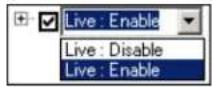
Certain functions can be Enabled or Disabled. E.g. Live mode.
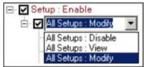
- Some functions can be set to Modify (can be modified), View (cannot be modified) or Disable (hidden). E.g. Setup tabs.
- PTZ channels can be set to PTZ (enable PTZ capabilities), View (view only, disable PTZ capabilities) or Disable (hidden). E.g. Channels : PTZ

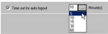
1.3.6.2. Auto Logout
The auto logout is configured for all users. Choose between the following options: 5, 10, 15, Time out for auto logout is checked and the logout time is configured, the users will be automatically logged out after the specified period of time.
1.3.6.3. Creating new user accounts
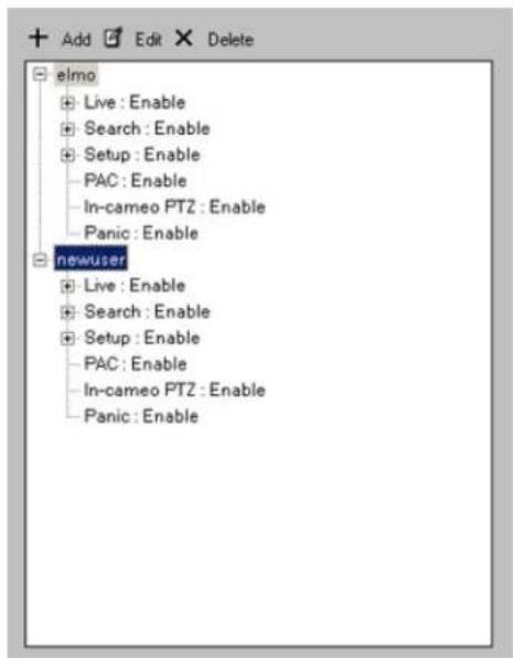
In order to create a new user account, do the following:
1.
Click the Add button.Add
A dialog will be displayed in the right pane for inputting new user information.
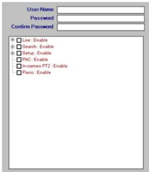
- Enter the User Name and Password (between 3 and 60 characters). Re-enter the password in the Confirm Password field. Copy and paste function is not supported, the password has to be manually re-entered.

- Enable or disable Live mode for the user. When live mode is disabled (no checkmark), no video channels will be displayed on the Main Screen in live mode. By default, the Live mode and all video char
When Live : Enable checkbox is checked, all channels are enabled and PTZ functions for all channels are available to the user.
- Select desired video channels for the new user if desired. Check the Channels : PTZ checkbox to enable all video channels.
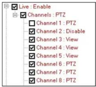
To display the list of all available video channels, click the plus sign next to Channels : PTZ entry. Checkmark the channels that will be visible to the user in the Live mode. The disabled channels (no checkmark) will be still visible in the Tree view, but the live video will be unavailable for the hidden channel.
To disable PTZ capabilities, double-click on the desired channel and select View in the drop-down menu. Checkmark the channel to activate the setting.
Note: If unchecked, the channel will be treated as hidden/disabled in the Live mode.
In the example below, Channels 1 and 2 will be disabled (hidden) from the selected user will be available for viewing only, if PTZ video inputs (cameras) are assigned to these channels, the user will be unable to control them. Channels 6-8 will be available for viewing and can be controlled by the
Notice that even though Channel 1 is set to PTZ, the checkbox is not checked, which makes Channel 1 disabled/hidden.
- Enable or disable Search and/or Backup for the selected user. By default, the Search and Backup for all channels are disabled.
To enable backup and search for all channels, check the Search : Enable checkbox.
To enable backup and/or search for individual channels, click the plus sign next to Search : Enable entry.
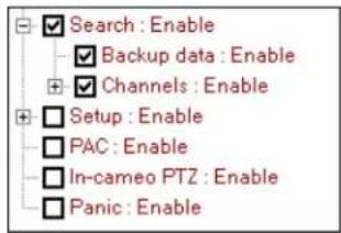
To enable the Backup window, check the Backup data : Enable checkbox . When disabled, new backup sessions can be created, but cannot be accessed/completed by the user.
To enable search on all video channels, check the Channels : Enable checkbox.
To display the list of all available video channels, click the plus sign next to Channels : Enable entry. Checkmark the channels that will be available for search. The disabled channels (no checkmark) will not in the Search mode (see image below).

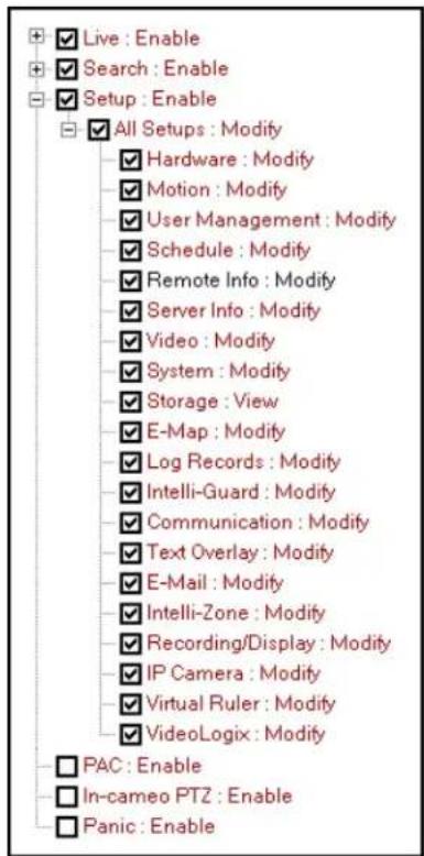
- Enable or disable access to the ELMO-PRO Setup for the selected user. By default, the use of ELMO-PRO Setup tabs.

To enable access to all setup tabs, check the Setup : Enable checkbox.
To display the list of all available setup tabs, click the plus sign next to Setup : Enable entry and then next to All Setups : Modify entry.
Every setup tab except for Remote Info can be configured to be disabled/hidden from u Every setup tab except for Storage can be configured to be edited by any user other than administrator.
To disable editing capabilities, double-click on the desired setup tab and select View in the drop-down menu. Checkmark the channel to activate the setting. When the setup tab is protected from modification grayed out to the user.
Note: If unchecked, the setup tab will be treated as hidden/disabled.
In the example below, Storage setup tab will be hidden from the user. All other setup to available for modifications.
-
PAC - check this checkbox to enable PAC application. To disable application, leave the checkbox unchecked. When PAC application is disabled, the PAC button on the main screen will also become disabled.
-
In-cameo PTZ - check this checkbox to enable the built-in mouse PTZ controls in PTZ mode. To disable in-cameo mouse function, leave unchecked.
-
Panic - check this checkbox to disable the panic backup function and the Panic button on the Main Screen.
-
Click Add User to add new user to the list or click Cancel to discard changes. After Add User is clicked, new user will be added to the list on the left-hand pane.
11.
Click the Save

to save the configured settings.
1.3.6.4. Editing existing user accounts
! Important
This function is not available on Remote
! Important
Permissions for administrator user cannot be changed. Only administer (elmo) can change the password user account.
It is possible to change password and/or permissions for existing user accounts.
ELMO-PBO To edit password or permissions for existing user account, do the followi
- Select desired user account from the user tree list on the left-hand pane.
2. Click the Edit button
-
Change user password if desired. Entries in the Password and Confirm Password fields must match.
-
Modify user permissions as desired. (See Step 3 in the Creating new user accounts
-
Click OK to finalize changes
6.
Click the Save

to save the configured settings.
1.3.6.5. Deleting existing user accounts
Important
This function is not available on Remote
To delete an existing user account, do the following:
ELMO PRO Select desired user account from the user tree list on the left-hand pane.
2.
Click the Delete

- The following message will be displayed to confirm your operation

- Click OK to delete
5.
Click the Save button to save the configured settings
1.3.7. Schedule Setup
1.3.7.1. Overview
Schedule Setup controls the type of recording for each channel: Continuous, Motion, Sensor or S schedule settings can be configured for each channel independently. The schedule settings from any to any other channel(s). The following types of recording are available for each channel:
Continuous recording - the selected channel records continuously. Continuous video recordings take up a lot of the hard drive space. Color code: pink
Sensor recording – the selected channel records only when the sensor has been triggered. The sensor has to be enabled and must be associated with a specific channel in the Hardware Setup. Color code: or
Motion recording - the selected channel records only when motion is detected. Motion detection target zones have to be configured in the Motion Setup. Color code: blue
Sensor + Motion recording - the selected channel records when the sensor has been triggered or motion is detected. The sensor has to be enabled and must be associated with a specific channel in code: green

Tip
Each channel can be assigned custom combination of these recording types based on the day of the week and time of the day.

1.3.7.2. Timeline
The schedule timeline can be zoomed into for easier navigation.
To zoom into the timeline, do the following:
1.
Right-click anywhere on the

- Select Zoom In from the context menu. Repeat if desired.
To zoom out of the timeline, do the following:
1.
Right-click anywhere on the

- Select Zoom Out from the context menu. Repeat if desired.
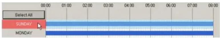
1.3.7.3. Basic recording schedule
To create a basic recording schedule, do the following:
-
Select the Channel # in the Current Channel frame. Click the Browse button to select the desired channel from the list.
-
A basic recording schedule may be created for:
a. Entire week (including custom schedule days)
Click Select All to select all days of the week, including custom schedule days. Entire recording area will be highlighted in blue.

To deselect, click Select All again.
b. Specific day(s)
Click SUNDAY, MONDAY, TUESDAY, WEDNESDAY, THURSDAY, FRIDAY, SAT-
URDAY or custom schedule to select a day. The selected day will be highlighted in
To deselect a day, click again.
- In the Recording Type menu, check off desired checkbox. Select on of the following recording modes: Continuous; Motion; Sensor; Sensor + Motion
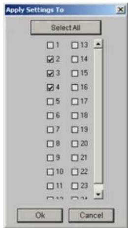
- Click Apply Settings to, to apply created recording schedule to other channels. A new window will be displayed. Check off the video channel check boxes to apply existing recording schedule to the selected example below, the schedule created for Channel 1 will also be applied to Channels 2-4.

5.
Click the Save

to save the configured settings
1.3.7.4. Advanced recording schedule
Advanced recording schedule allows customizing the recording schedule up to a minute.
To create an advanced recording schedule, do the following:
-
Select the Channel # in the Current Channel frame. Click the Browse button to select the desired channel from the list.
-
Position the cursor at the desired day and time on the timeline graph. The bottom pop-up exact time.
In the example below, the cursor is pointed at 1:02 AM.
The top pop-up time display will show the length of the recording type at which the cur In the example below, the cursor is pointed at the time block that is scheduled for Sens top pop-up time display shows that the channel is scheduled for sensor and motion recording (S) (M) from 1:00
AM to 2:00 AM
-
To select the desired time, left-click and drag the cursor until the desired area on the timeline graph is selected. The cursor can be dragged in any direction: horizontally to select time within one day or vertical one day at a time.
-
To deselect, repeat step 3 on the previously selected area on the timeline graph.
-
In the Recording Type menu, check off desired checkbox. Select on of the following recording modes: Continuous; Motion; Sensor; Sensor + Motion. In the example below, on Monday, the video channel will from 12:00 AM till 1:00 AM, from 2:00 AM till 2:20 AM and from 2:30 AM onward; 1:00 AM till 2:00 AM and continuously from 2:20 AM till 2:30 AM.
![Select All SUNDAY 01:00:00 AM - 02:00:00 AM (S) [M] MONDAY 01:02:00 AM TUESDAY](/content/2026/06/1226295/images/ad6e913009d60b627f6cf309228c3279e660801211228afb5de80b53f636af02.jpg)
- Click Apply Settings to, to apply created recording schedule to other channels. A new window will be displayed. Check off the video channel check boxes to apply existing recording schedule to the selected example below, the schedule created for Channel 1 will also be applied to Channels 2-4.
7.
Click the Save

to save the configured settings
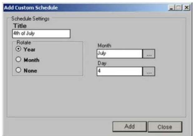
1.3.7.5. Add a custom schedule
ELMO-PRO software allows creating a custom schedule, such as a holiday recording schedule. The override the regular weekly schedule and can be repeated once, monthly or yearly. The custom at any time.
To create a custom schedule, do the following:
- Click Add Custom Schedule. A new window will be displayed.
-
Enter Title for the new scheduled date. In the example above, the custom name is "holiday".
-
Select the rotation option:
a. Select the Year radio button to rotate the new customer schedule yearly.
For yearly rotation, select the desired Month and Day of the recording. The custom schedule will be applied once every year based on the configurations. E.g. Independence Day holidays schedule. The will be highlighted pink on the schedule graph.
b. Select the Month radio button to rotate the new customer schedule monthly.
For monthly rotation, select the desired Day of the recording. The custom schedule will be applied once every month based on the configurations. E.g. 1st of every month. The custom schedule title w on the schedule graph.
c. Select the None radio button to create a custom schedule with no rotation settings.
To create a unique custom schedule with no rotation, select the desired Year, Month and Day of the recording. E.g. Easter 2008 (since Easter does not fall on the same day every year). The be highlighted yellow on the schedule graph.
-
Click Add. The new custom day will be added to the schedule.
-
Repeat steps 2-4 to create additional custom/holiday schedules
-
Click Close to close Add Custom Schedule window
-
Create recording schedule for custom date(s) (See Create a basic recording schedule and Create an advanced recording schedule for more details)
-
To add new custom day(s) to other channels, click Apply Settings to, to apply created recording schedule to other channels. A new window will be displayed. Check off the video channel check boxes schedule to the selected video channel(s).
9.
Click the Save button to save the configured settings
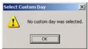
1.3.7.6. Delete a custom schedule
-
Select a custom schedule by clicking in the custom schedule title on the graph.
-
Click Delete Custom Schedule.
If no custom schedule has been selected, the following error message will be displayed.
3.
Click the Save button to save the configured settings
Related Topics: Hardware Setup-Channel Settings | Hardware Setup-Sensor Settings | Motion Setup | Video Setup
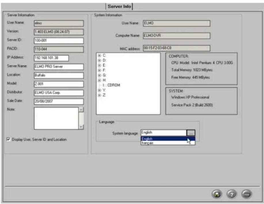
1.3.8. Server Info Setup
1.3.8.1. Overview
The Server Info Setup permits configuring the Server, changing the system's language, changing the system IP address, as well as obtaining information about the Server and the DVR.
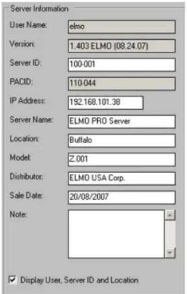
1.3.8.2. Configuring Server Info Setupz
In Server Information enter the following:

Tip
Remember this entry for remote access.
-
Server ID (disabled on ELMO-PRO Remote. Can only be changed on ELMO-PRO Server). Server ID is comprised of up to 31 alphanumeric characters. Please note that Server ID value is case sensitive
-
IP Address. You may enter a new IP address or change the one that is displayed. IP Address cannot be changed via ELMO-PRO Remote.

Tip
Remember this entry for remote
access.
- Server Name (optional)
- Location (optional)
- Model (optional)
- Distributor (optional)
- Sale date (optional)
To enter the sale date, select each position (i.e. day, month, year) and enter the desired Use virtual keyboard if necessary.
The date format can be changed in System setup tab. The sale date must be set to tl
-
Note (optional)
-
Check/uncheck Display User, Server ID and Location checkbox.
When checked, the current User logging in the server, Server Location and Server ID will be bar at the bottom of the main screen. This information is obtained from the Server Inform

10.
Click the Save button to save the configured settings
This section also displays the following:
- User Name
- Software Version number with release date
- PACID (only if PACDM software is installed)
System Information:
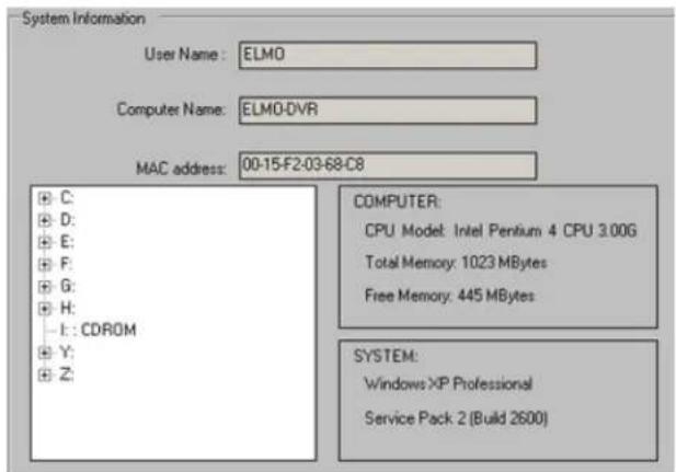
This section displays the following:
- User Name (currently logged in user)
• Computer Name (configured by manufacturer)
- MAC address
CPU Model
- Windows operating system version
• Total and free memory information
• List of drives/partitions
• Total and free space information
• Total and free memory (RAM) information
1.3.8.3. Language

Two languages are currently supported on the ELMO-PRO Server: English and French.
To change system language, select English or Français from the System Language drop-down menu. This will translate the ELMO-PRO Server interface into the appropriate language.
Click the Save button to save the configured settings
Related Topics: Main Screen | Search Window
1.3.9. Video Setup
1.3.9.1. Overview
Video Setup allows configuring brightness, hue, contrast and display mode (color/monochromel) for The settings are applied based on camera (physical BNC connector number), not based on chann

1.3.9.2. Configuring color settings
To configure color settings for desired camera, do the following:
- In the Current Camera frame, click the Browse button to select desired camera from the drop-down menu.
- In the Color Settings frame, set Brightness, Hue and Contrast for the selected camera using the horizontal sliders
- In Color/Monochrome frame, choose between Color and Monochrome recording. Color recording provides more realistic video images. Monochrome recording is best suited for low light conditi recording
- Click Defaults to reset camera Brightness/Hue/Contrast values back to 0 and to assign Color video recording to the camera.

-
Click Apply Settings to, to apply configured color settings to other cameras (not channels). A new window will be displayed. Check off the camera check boxes to apply existing color settings to the
-
Click OK
7.
Click the Save button to save the configured settings
Related Topics: Main Screen
1.3.10. System Setup
1.3.10.1. Overview
In the System Setup tab, the user can:
- Configure server restart time
- Enable watermarking feature
- Configure the PTZ Settings
- Configure login settings
- Configure alarm for video loss
- Configure sensor/Panic button backup
- Modify date display format
- Configure the Server System time
- Configure the NTP Server for system time synchronization
- Import/Export system settings
![System System Restart Select All Day Time (hrs : mins) Sunday 1 : 0 Monday 0 : 0 Tuesday 0 : 0 Wednesday 1 : 0 Thursday 0 : 0 Friday 0 : 0 Saturday 0 : 0 PTZ Settings Port: COM5 .... Port Speed (baud): 19.00 .... Watermark Enable Watermark Display Watermark Image Server System Clock 22/08/2007 05:45:52 PM Get Set Server Settings Export Import Video Loss Alarm Enable Control 1 .... Enable Alarm Working Time 0 ... H 0 ... M 10 ... S Backup Activate Sensor Backup Clock Display Date Format DD/MM/YYYY ... Time Format hit min or it ... Synchronize Time Enable Synchronize Systems Time With NTP Server [Daily Synchronize Time] 23 : 0 NTP Server List OS Login Settings Allow Automatic Logon User Name: elino Password: Confirm Password:](/content/2026/06/1226295/images/c8b8c73d4b151d0c5ffc18607d091f95f8aea9253229a9bea36071a241c348bf.jpg)
1.3.10.2. Configure System Restart Time
If the system freezes, it will be restarted by the I/O board. If, however the system is running smoothly without freezing, it can work for months without being restarted. The cache that will accumulate in that period slow the system down. To avoid this problem, it is advisable to set a weekly restart time
To configure the system to restart, do the following:
- Check individual day check boxes to select the day(s) for system restart. Click Select All to restart DVR daily.
- Enter the Time (hrs : mins) to restart the system
The time is in 24-hour format. In the example above, the system will be restarted at 1:0 nesdays.
3.
Click the Save

button
to save the
configured
settings
1.3.10.3. Watermarking
In the Watermark menu:
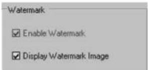
Enable Watermark option is always enabled and cannot be disabled. This option ensures that the recorded video is always watermarked.
Check Display Watermark Image to display the word "WATERMARKED" in green font on the watermarked video recordings during playback. Uncheck to hide "WATERMARKED" message during playback.
Click
the
Save

to save
the configured
settings
1.3.10.4. PTZ Settings
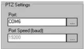
This section displays the COM port used for the PTZ camera(s) communications and the default Port Speed (baud rate).
COM6 is a built-in COM port on the I/O board, which is by default assigned to PTZ camer number is set to NONE, the PTZ cameras will not respond to user commands. It is thus n parameter.
Port Speed (baud) field displayed the initial default baud rate set by the I/O board. The baud rate set on the PTZ camera will override this initial port speed. This parameter is hard-coded and cannot be modified by th
By manufacturer default, Windows not require login and/or password. Windows O/S settings have been do not fill this section out.
0/S does Unless
changed,
In case when Windows O/S requires user name and password to login, automatic O/S login ca the user does not need to log into Windows O/S every time after the system restarts. Autor ELMO-PRO Server application immediately after restart, without having to login into Windows O/S
.Keep in mind, that the power outage or power spike may cause DVR to restart. Unless the the ELMO-PRO Server will not be initiated and no video recording will be made. This may c recording in cases, when DVR is unattended and the Windows O/S login is not completed.
To configure Windows O/S automatic logon, do the following:
- Check Allow Automatic Logon checkbox to allow the automatic Windows O/S login after the system restart
- Enter User Name and Password. Enter the password again in the Confirm Password field.
3.
Click the Save

to save the configured settings
Video Loss Alarm allows automatically initiating control and/or sound alarm upon video loss of one or more video channels.
To configure the Video Loss Alarm menu, do the following:
-
Check the Enable Control checkbox to enable control function for Video Loss Alarm
-
Click the Browse button to select desired control from the drop-down menu. In the example above, Control 2 will be activated after the video loss detection.
-
Check the Enable Alarm checkbox to initiate audible alarm after the video loss detection.
The Set Working Time for an audio alarm and selected control. In the example above, after the video loss has been detected on one or more video channels, the audible alarm will sound on the PC speaker 2 will be activated for 5 seconds (provided the video loss detection does not conflict with plicable).
- Click the Save button to save the configured settings
Related Topics: Hardware Setup-Control Settings | E-Mail Setup

Tip
Take into account the active time for selected control. The control active time configured in the Hardware Setup.

Tip
In the E-Mail Setup tab, check Enable E-mail for Video Loss to receive an e-mail every time video loss occurs on one of the channels.

Tip
To use this feature, ensure that there blank CD-R/DVD-R at all times in the drive.
1.3.10.7. Panic and Sensor Backup
Configure the recording settings for the main screen's Panic button feature and/or associate the backup with specific
is a sensor(s). If a Sensor is triggered, or the Panic button is clicked, an encrypted video backup will be burned onto a CD-R/DVR-R.
By default, the sensor/Panic button feature backs up 5 minutes of video recording prior to the sensor/Panic button activation. The user, however, can configure the length of time that DVR will record after the sensor/Panic button activation.
![Activate Sensor Backup When Panic button is pressed, or sensor is activated, the system will record 5 minutes pre-activation and 10 ... minute[s] post-activation Select sensors to activate a CD Backup ✓ Sensor 1 ✓ Sensor 9 ✓ Sensor 2 ✓ Sensor 10 ✓ Sensor 3 ✓ Sensor 11 ✓ Sensor 4 ✓ Sensor 12 ✓ Sensor 5 ✓ Sensor 13 ✓ Sensor 6 ✓ Sensor 14 ✓ Sensor 7 ✓ Sensor 15 ✓ Sensor 8 ✓ Sensor 16 ☐ All Ok Cancel](/content/2026/06/1226295/images/5a2ceb79314897e835808a16023a62abf5de875e50e36406b61beff8fb3fc987.jpg)
To associate a backup with the specific sensor(s), do the following:
- Click Activate Sensor Backup Activate Sensor Backup
- In the new window, click the Browse button to select from 0, 5, 10, 20, or 30 minute(s) post-activation recording time options.
- Check the corresponding check boxes for the desired sensors that will be associated with th
- Click OK or click Cancel to discard changes and to return to the Setup.

Note
The sensors must be enabled in Sensor Settings in Hardware Setup - Sensor Settings
Click the Save button to save the configured settings
In the example above: When the Panic button is clicked, or sensors 1 or 8 are activated, the encrypted backup will be created to the CD-R/DVD-R that will include 5 minutes of pre-activation and 10 minute recording (total - 15 minutes long).
To view the backup progress, enter the Search Mode by clicking the Search Mode button on by going to Tools -> Backup menu.
While the panic backup is in progress, the existing backup sessions cannot be edited/deleted and cannot be created.

Once the backup has completed, the following message will be displayed and the CD/DVD will
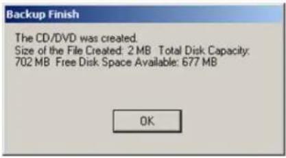
Related Topics: Hardware Setup-Sensor Settings
This setting will affect the way time and date is displayed on the main screen and in other setup tabs (such as Log Records, Server Info, etc.)
The clock can only be set forward, not backwards. To set the clock back, exit the software Windows operating system. If the time is set forward in the Server, it will automatically be applied to the Windows system time.
If the time change has been successful, the following window will appear:

If an attempt was made to set the time backwards, the following warning window will appea

This feature allows daily synchronizing the DVR system clock with one of the default NTP serving keeping the system time up-to-date without having to log out of the ELMO-PRO Server and up via Windows OS.
To use this feature, check off Enable Synchronize System Time With NTP Serve
Configure the Daily Synchronize Time (24 hour clock). The system time will be synchronized daily based on the configured time. The process may take several minutes.
![Synchronize Time Enable Synchronize System Time With NTP Server [Daily Synchronize Time] 23 : 00 NTP Server List](/content/2026/06/1226295/images/d5e3ff618137f152bdd8c7d534aae6746129230f6225f501135a4f51dcb4c9dd.jpg)
To select an NTP server, click NTP Server List. In the NTP Server List window, erase all NTP server entries except for the one that corresponds to your geographical location.
E.g. If located in US, leave us.pool.ntp.org and erase the rest of the NTP server entries.
Click OK to save the settings or click Defaults to restore the original list of NTP servers.
To use a different NTP server, erase all existing entries and enter the new NTP server address in the NTP Server List window. Click OK to save the settings.
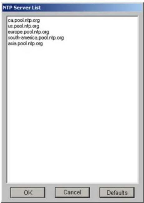
All user settings can be exported to a folder of choice for future use. In case of multiple servers, the same settings (including a list of users with permissions, and other server configurations) can be easily applied by importing them from the folder. This function saves a lot of time when many custom settings are used.

To export the system settings, do the following:
-
Click Export
-
In the Browse for Folder window, select the destination folder. Click OK.
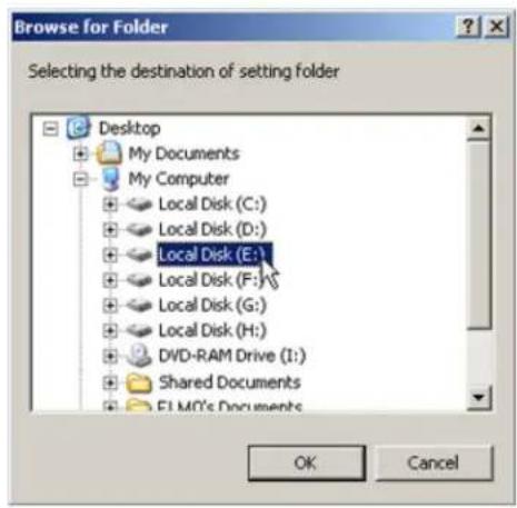
- The System Settings folder will be created on the selected drive (inside the selected folder if applicable). The following configuration files will be saved inside System Settings folder:
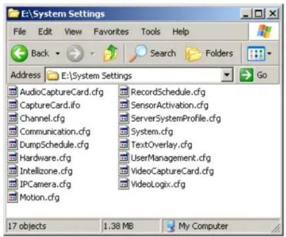
To import the system settings, do the following:
- Click Import
- In the Browse for Folder window, locate and select ELMO Settings folder. Click OK.
- Click Yes in the Import Settings warning window to proceed or click No to cancel the operation.
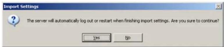

Note
The ELMO PRO Server will log out the current user after the settings have been successfully imported.
- Wait until the Login screen is displayed. Log into the ELMO-PRO Server to continue.

Important
The settings in this Setup tab cannot changed in any way through ELMO-PRO Remote

Important
Only the administrator user, elmo, can modify this setup tab.
ATTENTION: This function should be used by authorized technicians ONLY! The Storage Setup option is used to choose the drive for recording video data. It may stop recording or continue to overwrite old free space on the drive, depending on the option selected.
1.3.11.1. Understanding DVR storage structure
In order for the DVR to be able to record video data on a selected drive, the drives/partitions have to be structured in a certain way. After the initial allocation of the specific hard drive/partition, ELMO_DATA folder is created and the entire available space is filled with files that have the extensions *.dat and *.idx.
These files act as a medium for the digital video recording. The size of .dat files remains static regardless of whether or not they actually contain data ( 64MB). These files can be compared to video/audio tapes. They and take up the same amount of space whether they are empty, or when they contain data stored in the tree-structure of subfolders depending on the date of the recording: year, month,
For example, the subfolder F:\ELMO_DATA\2007\8\5 will contain video recordings from August 5, 2007
1.3.11.2. Overview
The Storage Setup displays the following:

Note
Drives C and D are protected from ting/allocating and are not displayed on list of drives.
- Recorded Data Path - displays the Drive name
Use for Recording - is used to select storage drives, where data is recorded. In the example below, drives F:\, G:\ and the H:\ are used for video recording. - Total Space/Free Space - displays used and available space
- Format - allows the user to select a drive to format.
- Recorded Time - displays the first and last time that data was recorded on a specific d
- When disk full - the user can decide the course of action when all local media is full: stop recording or overwrite old data
Select Stop Recording to cease all video recording when the hard drives are full.

Warning
This can potentially result in the loss of valuable video information. Once the drives are full, the DVR will stop recording.
Select Overwrite Old Data to write over the old data when the hard drives are ful

Warning
This can potentially result in the loss of valuable video information. Once the drives are full, the old video recordings will be overwritten. These video recordings will be lost and will not be restored. It is also to back up valuable video information on a separate removable, local or network drive that is not used for video recording.
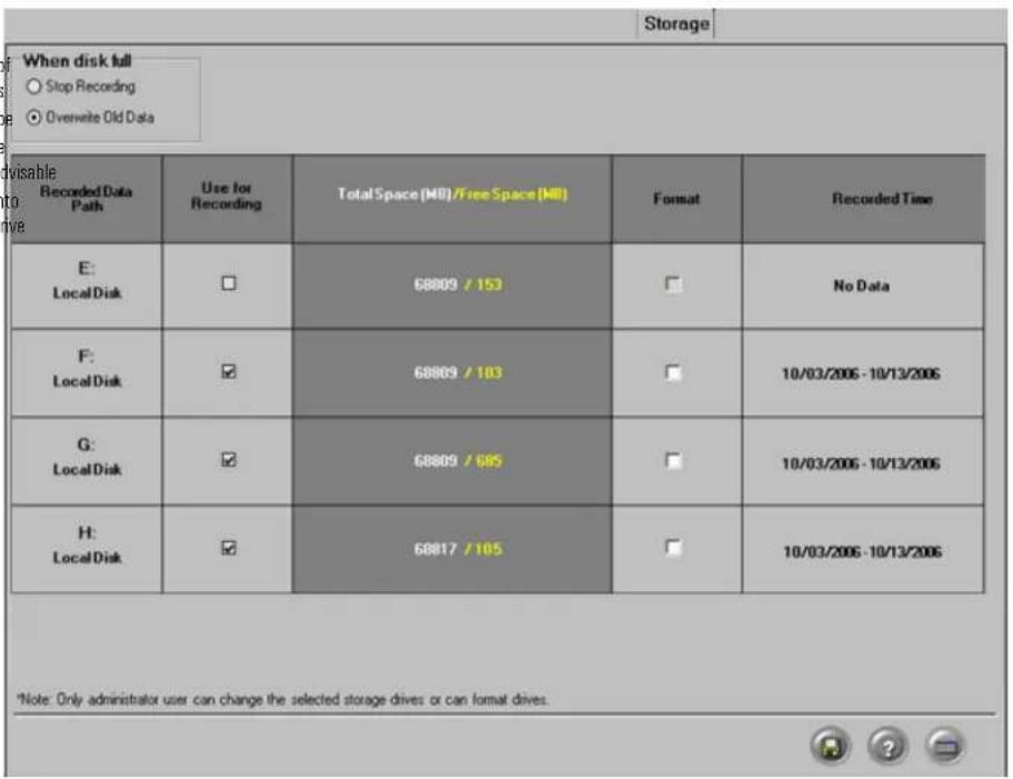
1.3.11.3. Allocating New Drives For Recording / Fo ting Hard Drives
In order to increase storage, administrative user (elmo) can allocate new local/network hard drives or format existing drives to free space for new video recording.

Warning
Allocation and formatting processes will erase all existing information on the drive. Make sure to save all valuable information onto another drive before proceeding.
To allocate a new drive for video recording or to format hard drive with formation, do the following:
Check the corresponding checkbox in the Use for Recording column to allocate new drive OR

Important
Drives C: and D: cannot be allocated/formatted.
-
Check the corresponding checkbox in the Format column to format existing hard drive.
-
Click OK in the Format Disk warning window to proceed or click Cancel to return to Storage Setup.

3.
Click the Save button to proceed with hard drive allocation.
- Depending on the When disk is full setting, one of the following messages will appear. Click OK to proceed.
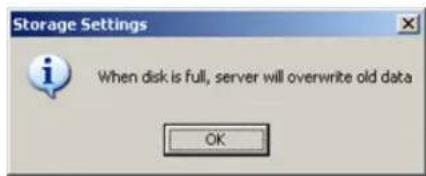
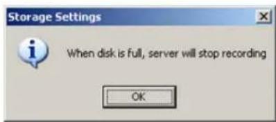
- Wait for the following message to be displayed in the top left corner:
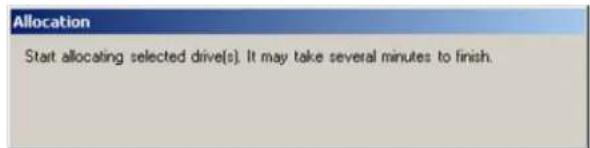
- Wait for the following message to be displayed in the top left corner. Click OK to finish

1.3.12. E-Map Setup
1.3.12.1. Overview

Important
This function is not available on Remote

Note
E-map does not allow manual activation of a control. However, if a control/sensor is triggered, it will be registered on the E-map: the icons representing the sensors/controls will be animated. E.g. If the control is activated, the control icon on the E-map will flash.
The E-Map function allows the users to lay out channels on a map for the quick launch of the channels, controls and sensors is done on an existing digital drawing/map. The map app and allows quick access to the desired channel by simply clicking on its representative icon. Clicking on a channel's icon will display the image of that channel in full-screen mode.
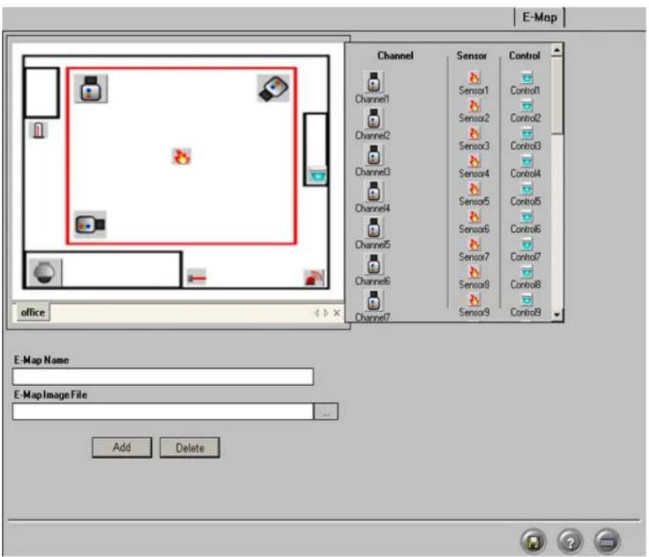
1.3.12.2. Configuring E-Map
To configure the E-Map, follow these steps:
-
Enter the E-Map Name. Use the keyboard or the virtual keyboard if necessary. In this example, the new E-Map name is "office".
-
Click the Browse button in the E-Map Image File field to locate and select existing digital image of the perimeter map.
-
Click Add Add to copy the selected image to the drawing area. The Image will appear in the screen on the left side of the Setup window. The new E-Map name will be displayed on the tab
-
In the right side of the drawing area, choose the number and Channel, Control or Sensor type to be positioned on the E-Map
a. Click on the Channel icon to display all available camera icons. The first 16 icons represent possible camera angles. The last icon represents a speed dome camera.
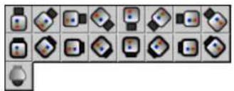
natural_image
Grid of 20 abstract geometric icons in various shapes and colors, no text or symbols present
Note
Only channels enabled in the Hardware Setup are displayed.

Note
Only sensors enabled in the Hardware Setup are displayed.

Note
Only controls enabled in the Hardware Setup are displayed.

Tip
Any one specific channel/control/sensor can only be used once
b. Drag and drop the desired channel icon onto the E-Map bitmap image in the drawing be added onto the image.
c. Click on the Sensor icon to display all available sensor icons: 📄→ 📃. The icons represent Fire, Laser and Heat sensors respectively.
d. Drag and drop the desired sensor icon onto the E-Map bitmap image in the drawing a added onto the image.
e. Click on the Control icon to display all available control icons: 📄. The icons represent Light and Alarm controls respectively.
f. Drag and drop the desired control icon onto the E-Map bitmap image in the drawing a be added onto the image.
5.
Click the Save button to save the configured settings
1.3.12.3. Delete the Channels/Controls/Sensors from a Emap
To delete Channels/Controls/Sensors, do the following:
- Click on the Channel, Control, Sensor icon in the E-Map image.
- Drag and drop the channel, control or sensor icon from the image back to the list of the right .The icon will disappear from the image.
1.3.12.4. Delete the E-Map bitmap image, do the ing
To delete/change the E-Map bitmap image, do the following:
- Select the tab with the desired E-Map in the drawing area.
2.

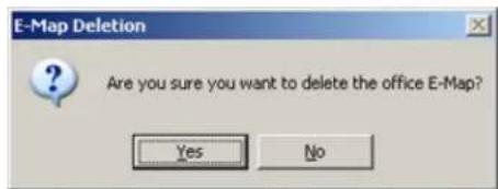
- Click Yes to delete or No to return to the E-Map setup.
1.3.12.5. E-Map on the Main Screen

To view the E-Map on Live Mode, click the Live button to go to the Main Screen. Click on Tools -> Emap Viewer menu. The E-Map window will be displayed in the center of Main Screen as a separate window. Emap Viewer window can be moved around the main screen as needed.
By clicking on any channel icon on the E-map, the corresponding channel will be brought to
Related Topics: Main Screen | Hardware Setup-Sensor Settings | Hardware Setup-Control Setti
1.3.13. Log Records
1.3.13.1. Overview
Once the user accounts are configured, the Manager can track user activity in the Log Record: erased from the DVR by administrator user, however the Log Records cannot be altered by ar the following activities: user login/logout activities, changes made to any of the setup tabs, sensor activation, sent E-mails, hard drive formatting, etc. The logs can be viewed in the Log Records setup tab or

Tip
All log activities are stored and according to date.
organized
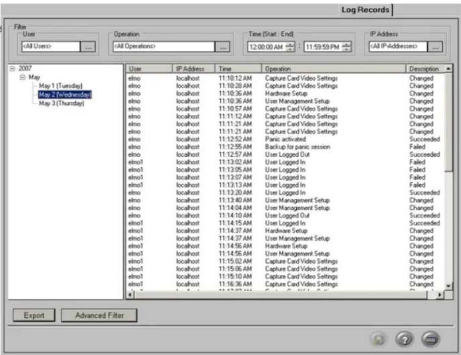
1.3.13.2. Exporting Log Records
To export specific log file, do the following:
-
Click the plus sign (+) next to the desired year. The list of months with log records
-
Click the plus sign (+) next to the desired month to view all entries for that month
-
Select a particular day in the tree view list. In the example above, May 2 (Wednesday) is selected in the list.
- The activity log for the selected day will appear in the right-hand pane
The word "Changed" in the Description column signifies changes made to the specific setup tab.
The word "Succeeded" signifies successful completion of an operation (such as user login)
The word "Failed" signified failed operation.
The description will show "Connection has failed" when the system was unable to connect to the mail server.
- Click Export to export the displayed log into a text file
- Choose the destination folder to save the log information
- Name the new text file.
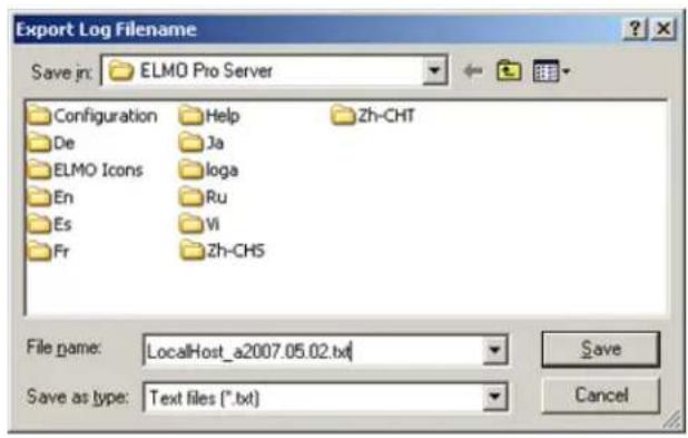
- To view the log text file, locate the exported log file in the destination folder and double-click it. The log file will open in Notepad.
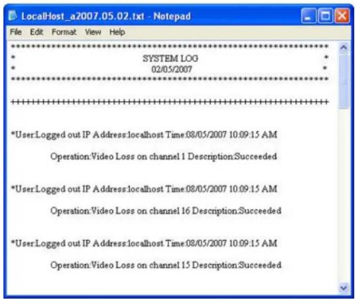
1.3.13.3. Configuring the Filter
To view and export filtered log files, you can filter the log info based
- A User
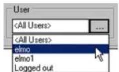
- An Operation

- A period of Time (Start : End)
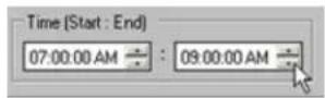
- An IP Address
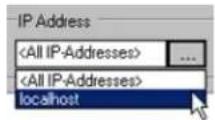
1.3.13.4. Advanced Filter
Advanced filtering based on date is available in the Log Records setup.
To display all log records for a period of time longer than 1 calendar day, click Advanced Filter.

In the Advanced Filter window, select the Start date and End date from the drop-down menus. In the example above, the log record for the period from January 30, 3007 to February 1, 2007 inclusive w
Click Filter to display the log records for the configured time period.
1.3.14. Intelli-Guard™ Setup
1.3.14.1. Overview
The Intelli-Guard™ feature detects motion within a defined area of the channel's view and can or emergency e-mail. Intelli-Guard™ requires precise settings in order to work effectively.
Intelli-Guard™ detects change in an image by analyzing its pixels. The same principle is used b feature. However, Intelli-Guard™ can yield a more precise response than Motion detection, as it can be adjusted to different kinds of motion. For example, an object's size in the Intelli-Guard module can be used to limit detection to larger objects only. Motion detection, on the other hand, recognizes and registers any type of motion.

Important
Intelli-Guard™ uses the e-mail address configured in the Email Setup. For this option to work, the Email Setup tab must be properly configured.

Important
This feature is not supported with IP cameras.

1.3.14.2. Suggestions for using Intelli-Guard™
- Before setting a defining area, experiment with the specific location to test the parameter s Intelli-Guard™ works as expected. Test both real alarm and false alarm situations. Adjust the eliminate the number of possible false alarms.
- It may be difficult to achieve good results if the image video contrast is low. Adjust the image brightness and contrast in the Video Setup tab to achieve better results.
- Intelli-Guard™ is best used in an environment with little color variation. For instance, if the monitored object is placed on a one-color background, any change (e.g. an intruder) will be noticeable, therefore easily
1.3.14.3. Creating Intelli-Guard™ detection area(s)
Each detection area has its own configuration and has to be saved individually. Up to 5 detection areas can be configured. Each detection area can have its unique set of settings, including Active Time, custom alarm file, control, etc. To switch between detection areas, select the chosen detection area by clicking on the desired green box. Selected detection area will be highlighted in red.
To create Intelli-Guard™ detection area, do the following:
-
Select the Channel # in the Current Channel frame. Click the Browse button to select the desired channel from the list, selected channel will be displayed in the live view window.
-
Configure Interval Alarm by adjusting the slider. In the example above, Interval Alarm is set to 400ms. Interval Alarm is configured on per channel and not per area basis. Interval Alarm setting determines between the motion occurrence and motion detection.
-
Create the detection area(s) in the live view window.
a. Place the mouse cursor at the start point over the live view window
b. Hold down the left mouse button and drag the cursor to draw the rectangular detector
c. Let the mouse button go
d. Adjust or move the created detection area if necessary
-
Click Area Draw to set the entire channel screen for motion detection
-
Click Area Clear to reset all detection area on a selected channel
-
To delete a specific detection area, select the area by clicking on it, hold down the left area to remove it from the live view screen.
7.
Click the Save button to save the configured settings
1.3.14.4. Configuring Intelli-Guard™ detection area(s):
To configure selected Intelli-Guard™ detection area, do the following:
-
Select desired detection area in the live view window. Settings for the selected detection z the Area No. frame.
-
Enter a descriptive name for the selected detection area in the Area Name: field. In the example below, Area No. 1 is called "warehouse".
![Area No.1 Area Name: warehouse Send E-Mail Never Update Background Control 1 ... [Time] 0 ... H 0 ... M 5 ... S Enable Sound D:\data\sound data\alarm.wav ... Background Refresh Delay: 1s 1800s Detection Sensitivity: 0.10 0.97 Detection Size: 10p 100p Duration of Sound: 1s 99s Set Active Time](/content/2026/06/1226295/images/c3231d7e6bcf504d9ddbd88ac0fafa8b2af42d65fc700f58424c5bb26832f971.jpg)
-
Check Send E-Mail checkbox to have an emergency Email sent every time an alarm is triggered in this Area. The email address is taken from the Email Setup tab. Make sure to configure E-Mail setup
-
Check Control checkbox to activate selected control every time an alarm is triggered in this Area.
-
Click the Browse button to select the desired control from the list. Only controls activated in the Hardware Setup tab will be displayed.
-
Set the working [Time] for the selected control. After the control has been activated, it will remain on for the set period of time. In the example above, Control 1 will remain on for 5 seconds after the the Area No. 1.
-
Check Enable Sound checkbox to enable custom audio alarm for the selected area.
-
Click the Browse button to select the desired *.wav sound file from the hard drive.
-
Locate the *.wav sound file and click Open
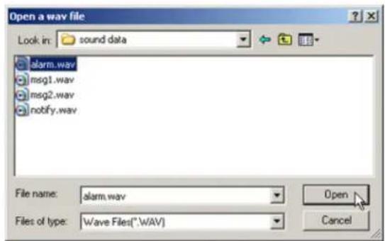
-
Set Duration of Sound by adjusting the slider (1 sec - 99 sec) to determine how long the *.wav file will play.
-
Set Background Refresh Delay (1s - 1800s). If Intelli-Guard™ detects no changes in the monitored area, it will update the area picture according to the selected schedule. This will decrease the cause caused by normal occurrences, such as changing illumination across the period of a day. The can be set between 1 second and 1800 seconds (30 minutes). To disable background refresh feature, check Never Update Background checkbox.
-
Configure Detection Sensitivity (10% - 97%). This parameter accounts for the change in image brightness. This percentage determines the acceptable level of brightness change. If the illumination is incre evenly, it is unlikely to cause an alarm. However, if the light switch is suddenly turned on in a dark room, the dramatic change in image brightness will set off the alarm.
-
Configure Detection Size (10p - 100p). This parameter determines the number of pixels representing 1 (one) "block". At least one block has to be detected by Intelli-Guard™ to trigger the alarm. The smaller the size of the block, the more "sensitive" Intelli-Guard™ will become and the smaller the size of the objects that will set off the alarm.
For instance, assume that a bird occupies 10 pixels in a resolution of 640x480. If the Detection Size is set to 10 pixels, the bird will represent 1 block; therefore the alarm will be triggered. However, if the Detection Size is set to 20 pixels, the bird will no longer represent 1 block and will be omitted by the Intelli-Guard™. A larger Detection Size, thus, detects larger objects (e.g. people) and omits smaller ones. This setting is used to decrease the nu configuring this setting, it is important to run trials to ensure that the Detection size is reacting to objects of a desired size. On the screen, the area of a detected change will be indicated by, green outline wi indicates how many detection blocks make up the area.
In the example above, motion was detected in an area, which is made up of 5 detection of detection blocks shown on the live view screen, select Show in Detection Box frame. To hide them, select Hide.

- Click Set Active Time to configure active time for the selected area. Intelli-Guard will detect motion in the selected area ONLY during the Active Time. The following window will appear.

- Check desired active time(s) for the selected area. In the example above, the Intelli-Guard motion detection in Area No. 1 is active 24 hours a day.

Caution
Active Time MUST be set, otherwise IntelliGuard™ will not work for the selected detection area.
Click the Save

to save the configured settings
16.

Caution
Ensure there is NO MOTION occurring in the defined area when clicking the Save button, otherwise the Intelli-Guard™ function will not work properly for that area. This is due to that fact that Intelli-Guard™ detects changes in the pixels that make up an image as opposed to detecting actual motion. When the Save button is clicked, Intelli-Guard™ registers the current image as the default image. All consequent changes to that area will be registered. If motion occurs in the defined area when the Save button is clicked, even the static environment will set off the alarm.
Related Topics: Hardware Setup-Control Settings | Email Setup
1.3.15. Communication Setup
1.3.15.1. Overview
Communication Setup contains the network type, bandwidth setting, Text Overlay port and Other
The network type is displayed based on Windows O/S settings and cannot be changed by the value should not be changed for the PACDM software to function properly.

1.3.15.2. Configuring Communication Setup
To configure Communication Setup, do the following:
- Configure Bandwidth. This menu controls the bandwidth of the data transferred over the network. Choose No Limit to use all the available connection speed to transfer data. If No Limit is chosen, the Server might be slowed down in cases where multiple users are dialing into the system at the same time.
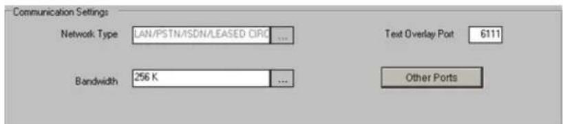
-
Enter Text Overlay Port number. The default port number is 6111 for text overlay via TCP/IP. Enter 5111 to display text through the COM port. The user must restart the server to apply changes to
-
Click Other Ports to display all ports used in the ELMO-PRO Server application. It is recommended to keep the default port numbers, especially the Main Control Port, which is required to be the same if for remote connection to be possible. Unless a port designated as a default is required for to change the port numbers.
Important
This feature is not available on Remote.
![Other Ports Main Control Port 17221 Search - Live Port 17222 PAC Database Download Port 7500 Backup Port 1 48021 Backup Port 2 48022 Backup Port 3 48023 [Valid port range is from 5001 to 65535] Defaults OK Cancel](/content/2026/06/1226295/images/e3958f6b66a88d14626c6a6ada21f3bbd3c0a04adac7e9d635babd834bce3a33.jpg)

Important
This feature is not available on Remote.
ELMO PRO
1.3.16. Text Overlay Setup
1.3.16.1. Overview
The ELMO-Pro Server be configured to display and capture current PACDM™ activity on any cha PACDM™ support.
SPK key dependent, there is a number of channels supported Text Overlay can be activated. In user can not activate any channel for Text Overlay.

1.3.16.2. Setting up Text Overlay
To set up Text Overlay on a channel, follow these steps:
- Click Setup on the main screen
- Click the Text Overlay tab
- Select the channel where text overlay will be displayed
- On the video window draw a rectangular box around the area desired for text overlaid
- Select Black or White for the text color. Selecting Intelligent will set the text color to the opposite color of the background. Example: If the background is dark the text color would be white. If the background is bright the text color would be black.
- In Intelligent mode, adjust the Brightness according to the desired background sensitivity
- Enter the Scroll Delay to determine the number of frames delayed when text scrolls up
- Enter the Text Delay Time. If there is no text input for a long time, the text will disappear automatically
- Enter Virtual Ruler setup tab, check Show Text Overlay/Virtual Ruler in Mux Dis Server to show text overlay in the live view window.
1.3.17. Intelli-Zone™ Setup
1.3.17.1. Overview
Intelli-Zone™ is a feature that allows the channel to intelligently pan, tilt, or zoom to a specified preset. The ELMO-PRO Server will automatically detect if that channel has P/T/Z features and adjust the pan-, tilt-, or zoom- settings where applicable.

Important
This feature is not supported with IP
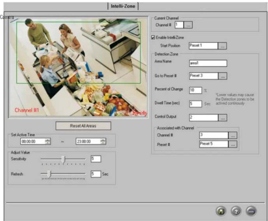
To configure selected channel for Intelli-Zone, do the following:
- Select the Channel # in the Current Channel frame. Click the Browse button to select the desired channel from the list, selected channel will be displayed in the live view window.
- Check Enable Intelli-Zone checkbox to enable Intelli-Zone module for the selected channel
- Select Start Position preset. This is the position the channel will return to after the specified dwell time. Click the Browse button ... to select the desired preset from the list. (Please see Programming Presets section for more information).
- Set Active Time to configure Intelli-Zone™ active time on the selected channel. Intelli-Zone™ will not work outside of the Set Active Time. In the example above, Intelli-Zone™ will work from 12:00 Channel #1.
- Adjust Sensitivity. The higher the Sensitivity, the less change in an image is needed to set off the alarm. If the all Sensitivity is set to Low, the change in an image will have to be dramatic to be detected only works properly indoors. The natural changes an outdoor environment (e.g. clouds) can cau

Note
Active Time will remain the same for detection areas on the selected channel.

Note
Sensitivity will remain the same for all tection areas on the selected channel.

Note
Refresh time will remain the same for all detection areas on the selected channel.
- Set Refresh time. Refreshing an image more often will decrease the cumulative image difference caused by normal occurrences, such as changing illumination across the period of a day and will reduce the
1.3.17.2. Creating Intelli-Zone™ detection area(s):
To create Intelli-Zone ^™ detection area(s), do the following:
- Place the cursor over the start point on the live view window
- Hold the left mouse button down and drag to create a rectangular area
- Let the mouse button go
- Move/adjust the area if necessary
- To delete a target area, click the area to select it, hold the left mouse button down from the live view window
- To erase all created areas, click Reset All Areas
1.3.17.3. Configuring Intelli-Zone™ detection area(s):
Each detection area has its own configuration and has to be saved individually. Up to 10 detection areas can be configured. Each detection area can have its unique set of settings, including Area Name, Go to Preset; Time, Control output, and Associated Channel. To switch between detection areas, select the chosen clicking on the desired green box in the live view window. Selected detection area will be h
- Select the specific detection area by clicking it in the live view window. Selected detection area is highlighted in red.
- Enter Area Name for the created target zone in the Detection Zone frame. In the example above, the detection area has been labeled "area1".
- Select Go to Preset # . This is the position the PTZ camera will move to after the motion has been detected in the selected detection area. Click the Browse button ... to select the desired preset from the list. All presets are configured in the PTZ Mode. (Please see Programming Presets section for more information above, Channel #1 will move to Preset 3 when motion is detected on area1.
- Set the Percent of Change between 1% and 99%. This value determines the amount of change that has to occur in the image in order to be recognized. In the example above, the image change h to be recognized by Intelli-Zone.
- Enter the Dwell Time (sec) (5-99 seconds). Dwell Time defines the number of seconds the selected channel will remain in the Go to Preset position before returning to the Start Position. This Dwell Control output. In the example above, Channel #1 will remain in Preset 3 for 5 seconds Control Output will remain active for 5 seconds after the motion has been detected on are
- Assign the Control Output that will be triggered after the motion has been detected in the selected detection area. Click the Browse button to select the desired control from the list. Only controls activated in the

Caution
Lower values may cause false alarms.
Hardware Setup tab will be displayed. In the example above, Control 2 will be activated at detected in area1.
- If desired, associate selected detection area with another channel:
a. In the Associated with Channel frame, click the Browse button in the Channel # field to select the desired channel from the list. Only channels activated in the Hardware Setup tab will be
b. Click the Browse button ... in the Preset # field to select the desired preset from the list. (Please see Programming Presets section for more information).
Associated channel will assume this position when motion is detected by Intelli-Zone in the area.
In the example above, Channel 3 will assume Preset 5 if the motion has been detected #1.
8.
Click the Save button to save the configured settings

Caution
Ensure there is NO MOTION occurring in the defined area when clicking the Save button, otherwise the Intelli-Zone™ function will not work properly for that area. This is due to that fact that Intelli-Zone™ detects changes in the pixels that make up an image as composed to detecting actual motion. When the Save button is clicked, Intelli-Zone™ registers the current image as the default image. All consequent changes to that area will be registered. If motion occurs in the defined area when the Save button is clicked, even the static environment will set off the alarm.
Related Topics: PTZ mode | Hardware Setup-Control Settings | Motion Setup
1.3.18. IP Camera
1.3.18.1. Overview
Assuming the user has an IP camera module present on LAN (Local Area Network) or WAN tional cameras can be added to ELMO-PRO Server through a LAN or WAN.

Important
Even though the IP modules located on WAN are supported, it is highly recommended to use IP modules on LAN ONLY the Internet connection is a lot less than the network connection, the video cording is a lot more stable and reliable LAN.
The IP camera function is designed to work with the IP camera module. Currently ELMO-PRO S IP modules: Annexus104, Annexus204, and Annexus101M.

Caution
Only one module type can be same time.
used at the
Annexxus104 module supports the following resolutions:
-
320X240 (max. 4 video inputs per IP module; max. 30 fps per input)
-
640x240 (max. 3 video inputs per IP module; max. 30 fps per input)
-
720x480 (max. 1 video input per IP module; max. 30 fps per input)
-
640X480 (max. 1 video input per IP module; max. 30 fps per input)
The number of IP cameras that can be added to ELMO-PRO Server will vary depending on S present, no IP cameras may be added to IP Camera setup.
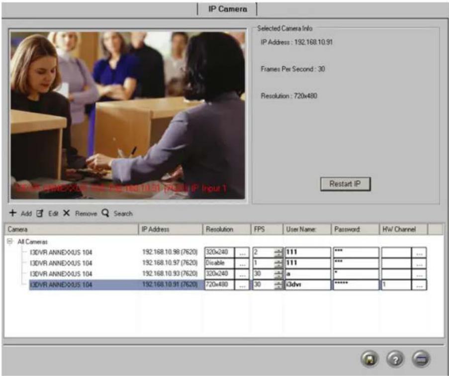
1.3.18.2. Add IP Camera
Use the instructions below when the IP address of the Annexus module/IP camera is known module/IP camera is located on WAN.
To add IP camera, do the following:
1.
Click the
Add

- The following will be displayed in the Selected Camera Info frame:
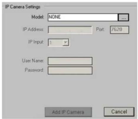
- Click the Browse button to select the IP Module Model from the list. In the example below, I3DVR ANNEXXUS 104 has been chosen.
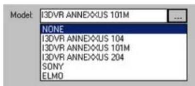
- Enter the IP Address of this IP camera module/IP Camera. It is not recommended to change the default port number.
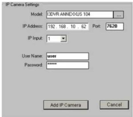
-
Choose the IP Input from the drop-down menu. This is IP Module camera's input number. Each Annexus104 and Annexus204 IP module supports up to 4 camera inputs. Annexus 101M IP module supports
-
Enter the User Name and Password of user, who will have permission to view this IP camera. Each Annexus module allows adding a list of users that are permitted to connect to the IP cameras). I do not match Annexus user database, IP camera resolution will be adjusted to "Disabled". This IP camera will then be treated as video loss on Live Mode.
-
Click Add IP Camera. The configured IP camera will be added to the list of IP cam

- After the new IP camera has been added to the list, the following parameters may be adjusted. (Click the Save
button after adjusting any parameters).
a. Resolution. Choose from 4 available resolutions. 320x240, 640x240, 640x480, 720x480
b. FPS (frames-per-second rate). This fps setting is used for recording. This fps setting is also used on Live Mode (Mux display), while IP camera is in the full screen mode. When any other screen divis will be displayed at 1-3 fps rate.
c. User Name/Password. If the user name/password is incorrect, IP camera resolution will be adjusted to "Disabled". This IP camera will then be treated as video loss on Live Mode.
d. HW Channel. Each IP camera can be linked with any number of video Channels. In the example above, Channel #1 will display IP Camera at 192.168.10.91; Channel 2 will display IP camera at Channels #3-4 will display IP camera at 192.168.10.80.
The Video Channels can also be linked with IP cameras in the Hardware Setup tab. To Camera, select the desired IP Camera address in the Video drop-down menu.


Note
Each channel can be linked with IP Camera at a time.
- While IP camera is selected in the All Cameras list, it is displayed in the live view window. The following inform-
only one ation will be displayed in the IP Camera Settings frame: camera's IP Address, Frames Per current resolution.

- To restart the corresponding Annexus IP module, click Restart IP
11.
Click the Save button to save the configured settings
1.3.18.3. Find IP Camera
Use the instructions below when Annexus module IP address is unknown and/or when the Ann on LAN.

Note
The search command works on LAN only. The server must be on the same LAN IP module (Annexxus). IP module(s) is located on WAN will not be displayed with search command.
To find IP Camera, do the following:
Click the Search button. Search Wait for the following window to appear:
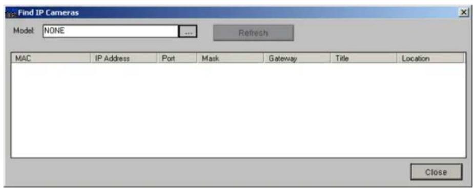
- Click the Browse button to select the IP Module Model from the list.

- The list of all available IP cameras on LAN will be displayed. The following information is available: MAC address, IP Address, Port used, Mask, Gateway, camera Title and server Location.

-
Click Refresh to update the list of IP Cameras.
-
From the list of all displayed IP cameras, select the desired camera by double-clicking on the list. The window will expand as shown below.

-
The lower portion of the window displays settings for the selected IP camera: IP Camera change either one, please refer to Edit IP Camera Settings and Edit IP Camera User Account
-
To add the selected camera to the list of IP cameras,
a. Open User Accounts tab
b. Select desired user account from the list
c. Click Select IP Camera Select IR Camera Selected IP camera with selected user account will be added to the list.
1.3.18.4. Edit IP Camera User Account(s)
To edit user accounts for the selected IP camera, do the following:
-
Select desired camera in the All Cameras list
-
Click the Edit button
-
Wait for the following window to be displayed.

- To add new user account,
a. Click Add
b. Enter new User Name and Password
c. Click OK. New user will be added to the selected IP Camera's User Accounts list.
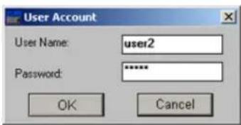
- To edit password for an existing user account,
a. Click on the desired user account in the list to select it
b. Click Modify
c. Enter Old Password and new Password
d. Click OK. New password has been saved.
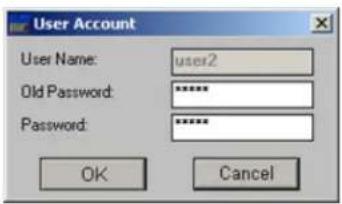
- To delete unwanted user account,
a. Click on the user account in the list to select it
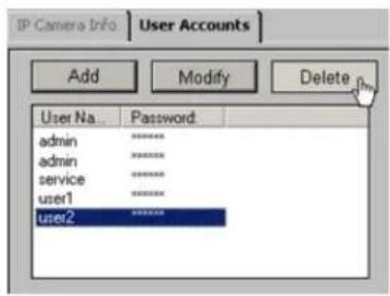
b. Click Delete
c. Click OK in the warning window. The user account will be deleted from the list.

1.3.18.5. Edit IP Camera Settings
To edit IP camera settings, do the following:
-
Select desired camera in the All Cameras list
-
Click the Edit button
-
Wait for the following window to be displayed
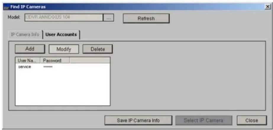
- Click the IP Camera Info tab

- In the IP Camera Info tab, the following can be changed:
• Server IP (Annexxus module/IP Camera IP address)
- Server Subnet (It is advisable not to change the default value)
- Server Gateway
• Server Title (optional)
• Server Location (optional)
Server MAC address is also displayed in this setup tab. This value cannot be changed by

Caution
It is advisable that only network or makes changes to this setup
6.
Click Save IP Camera Info to save settings. This will save both user account administration and IP camera information.
1.3.18.6. Delete IP camera
To delete an IP camera, do the following:
-
Select desired camera in the All Cameras list
-
Click the Remove button Remove The IP camera will be removed from the list.
Related Topics: | Hardware Setup Control Settings
1.3.19. VideoLogix™
1.3.19.1. Overview
VideoLogix™ is an intelligent human(vehicle) tracking / theft detection module. This module allows:
- Detecting Human Presence
- Detecting a Vehicle
- Detecting a Missing Object
-
Analyzing Human/Vehicle behavior
-
Initializing pre-selected response depending on the nature of the behavior
The total number of available VideoLogix™ channels will depend on the DVR model. Please contaVideoLogix channels are desired.
The VideoLogix™ tracking module is a versatile device that allows for seven different types of and tracking: Area, CrossWire™, Idle, Missing, Stop, Direction, Passthrough Counter™.
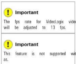
channels


1.3.19.2. Configuring VideoLogix™
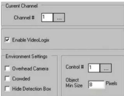
To configure the common channel settings, do the following:
- In the Current Channel field, click the Browse button to select the desired analog video channel. Note that VideoLogix cannot be configured on IP channels.
- Check the Enable VideoLogix checkbox to enable the VideoLogix™ module for the selected channel. In the example above, VideoLogix™ is configured for Channel 1. Note that the maximum frame-per-seco channels configured for VideoLogix™ is 13 fps. When the channel is configured for VideoLogix, automatically adjusted to 13 fps.
- Choose the Control # in the drop-down menu for the selected VideoLogix™ channel. When the alarm is triggered on the selected VideoLogix™ channel, the configured control will be activated. In the example turn on when the VideoLogix™ alarm is triggered on video Channel 1.
- Set Object Min Size. This pixel value is the minimum pixel height that the human form has to represent on the live-view screen in order to be detected by VideoLogix™. By default, this value is set value of 8 pixels. Any objects smaller than the selected object minimum size will not be
- If necessary, configure the environment for the selected channel. Check Overhead Camera checkbox if the selected camera is facing downwards. Check Crowded checkbox if the selected camera is mounted in a crowded location. Please note that only one of these two checkbox can be selected at any given

Note
The environment limitations, such as restricted camera view due to the mounting direction or the crowded site will restrain via Logix™ functionality. If Overhead Camera is checked, only Missing and Passthrough Counter alarm options will be available. If Crowded is checked, only Direction alarm option will be available.
- Check the Hide Detection Box checkbox in order to hide the detection box on the
After configuration the common channel settings, choose and configure the desired type of human/ol Video-
1.3.19.3. Configuring Object/Alarm type
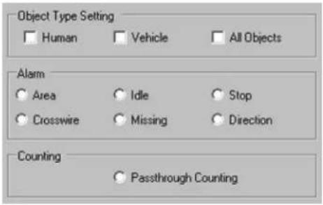
To configure the Object/Alarm type, do the following:
-
Choose the Object Type between Human, Vehicle, Human + Vehicle or All Objects.
-
Choose the Alarm type from seven possible choices:
a. Area (not available when Overhead Camera or Crowded options are checked)
b. CrossWire (not available when Overhead Camera or Crowded options are checked)
c. Idle (not available when Overhead Camera or Crowded options are checked)
d. Missing (available only for All Objects object type. Not available when Crowded option is checked)
e. Stop (not available when All Objects object type is selected. Not available when Overhead Camera or Crowded options are checked)
f. Direction (not available when Overhead Camera option is checked)
g. Passthrough Counter (not available when Crowded option is checked)
1.3.19.3.1. Configuring Area alarm
The Area alarm detects the human / vehicle / object presence in the defined area and initiat
Please note that the Area alarm option will not be available for the overhead-mounted cameras and in the crowded locations.

Caution
Due to the background registration technique the persons, who remain in the position, without moving, for an extended period of time will not be detected.
To configure Area alarm, do the following:
-
Choose Area in the Alarm menu.
-
Choose rectangular or polygon drawing tool
-
Draw the detection zone in the live view screen. A total of three Area alarm detection gular, polygon or both.
a. For rectangular area: Click on the live view screen to define the area starting point, hold down the left mouse button and drag to draw a rectangular area.
b. For polygon area: Click on the live view screen to define each vertex of the polygon. Click on the first point defined to complete the polygon.
c. To adjust the detection zone position on the screen, click on the desired detection zone, down and drag the selected zone to the desired position.
d. Click Undo to delete the last detection zone
e. Click Clear to delete all detection zones for the selected camera
f. Name the detection zone in the Area field if required. Enter the desired name in the text field under the live view window.

- Set the Active Time for each detection zone. In the example below, the Area alarm is active from 8:00AM to 5:30PM.

Important
Active Time must be configured. Unless the Active Time is set, object detection will not occur in the selected area.
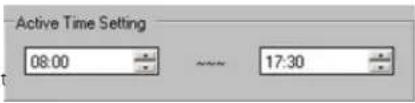
- Configure the Area Output Setting for the selected detection zone

a. Check the Send Email checkbox to send an emergency Email every time that the alarm is triggered in this detection zone. The email address must be configured in the Email Setup tab.
b. Check the Audio Dial Out checkbox to make an emergency phone call every time that the alarm is triggered in the Area.
c. Select the Sound Wave File for the audio alarm
a i. Click the Browse button ... and locate the *.wav sound file that will play every time that the alarm is triggered
ii. Click Open
- Set the Duration of Sound (1 - 100 sec) to determine how long the *.wav file v
- Configure the Area Alarm Setting for the selected detection zone by selecting one of the following conditions:
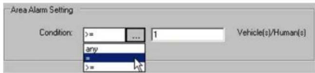
a. In the Condition drop-down menu, choose any to trigger an alarm every time human/vehicle/object presence is detected in the defined area.
b. In the Condition drop-down menu, choose “=” (equal to) in the drop-down menu and enter the desired number of persons/vehicles/objects. This way the alarm will be triggered only if the specified number jects is met in the defined area.
c. In the Condition drop-down menu, choose “> =” (greater or equal to) in the drop-down menu and enter the desired number of persons/vehicles/objects. This way the alarm will be triggered only if the persons/vehicles/objects is met or exceeded in the defined area.
1.3.19.3.2. Configuring CrossWire alarm
The CrossWire alarm detects any human/vehicle/object that crosses the specified boundaries in a pi and initiates an alarm.
Please note that the CrossWire alarm option will not be available for the overhead-mounted cam locations.

Caution
Due to the background registration technique the persons, who remain in the position, without moving, for an extended period of time will not be detected.
To configure CrossWire alarm, do the following:
1_ same Choose CrossWire in the Alarm menu
-
Choose the CrossWire drawing tool
-
Draw the detection zone in the live-view window. A total of three CrossWire detection alar
a. Click on the live view screen to define the starting point
b. Hold down the left mouse button and drag the cursor to set the end point. The arr in the desired location.
c. To adjust the detection zone position on the screen, click on the desired detection zone, down and drag the selected zone to the desired position.
d. To adjust the detection zone, click on start/end point, hold down the left mouse button and drag in desired location to expand/shrink or change the direction of the CrossWire detection zone
e. Click Undo to delete the last detection zone
f. Click Clear to delete all detection zones for the selected camera
g. Name the detection zone in the Area field if desired
- Repeat steps 4-6 of the Area alarm setup
1.3.19.3.3. Configuring Idle alarm
The Idle alarm detects a human/vehicle/object and initiates an alarm if the detected object remains for a period of time longer than that defined by user.
Please note that the Idle alarm option will not be available for the overhead-mounted cameras and in the crowded locations.
To configure Idle alarm, do the following:
-
Choose Idle in the Alarm menu
-
Repeat steps 2-6 of the Area alarm setup
-
Configure the Idle Alarm Setting for the selected detection zone. Set the Period of Time, in hours, minutes and seconds that an object is allowed to remain in the defined area. Once the p exceeded the allowed period of time, the alarm will be triggered.
In the example below, the alarm will be triggered if the person remains in the defined a

1.3.19.3.4. Configuring Missing alarm
The Missing alarm tracks any selected object and initiates an alarm if the object has been removed/moved from its original position. Available only with All Objects object type.
Please note that the Missing alarm option will not be available in the crowded locations.
To configure Missing alarm, do the following:

Important
All Objects must be chosen in Type menu in order to activate alarm type.
the Object Missing 3.
- Choose Missing in the Alarm menu
-
Repeat steps 2-6 of the Area alarm setup
-
Configure the Missing Alarm Setting for the selected detection zone. Set the Area Change Percent (0% - 100%). The higher the number, the more profound the change in the defined area the alarm. To detect the item being moved slightly from its original position, the Area Change Percent number should be set to a lower value.

1.3.19.3.5. Configuring Stop alarm
The Stop alarm detects a human/vehicle and initiates an alarm if the detected human/vehicle stop for a period of time longer than that defined by user.
Please note that the Stop alarm option will not be available for the overhead-mounted cameras and in the crowded locations.

Important
Human or Vehicle must be chosen in Object Type menu in order to activate Missing alarm type. Stop alarm will not work with All Objects object type.
To configure Stop alarm, do the following:
the 1. Choose Stop in the Alarm menu
2. Repeat steps 2-6 of the Area alarm setup
3. Configure the Stop Alarm Setting for the selected detection zone. Set the Period of Time, in hours, minutes and seconds that a human/vehicle is allowed to stop for in the defined area. Once in the defined area for the period of time longer than defined by user, the alarm will I In the example below, the alarm will be triggered if the human/vehicle stops in the defined seconds.
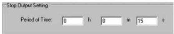
1.3.19.3.6. Configuring Direction alarm
The Direction Alarm detects any human/vehicle/object that moves in a predetermined direction and Please note that the Direction alarm option will not be available for the overhead-mounted came
To configure Direction alarm, do the following:

Caution
Due to the background registration technique the persons, who remain in the position, without moving, for an extended period of time will not be detected.
-
Choose Direction in the Alarm menu
-
Choose the Direction drawing tool
-
Draw the detection zone in the live-view window
a. Left-click on the live view screen to define the starting point
b. Hold down the left mouse button and drag the cursor to set the end point. The arr direction.
c. To adjust the detection zone position on the screen, hold the left mouse button down to the desired position.
d. To adjust the detection zone, click on start/end point, hold down the left mouse button direction to expand/shrink or change the direction of the CrossWire detection zone
e. Click Undo to delete the last detection zone
f. Click Clear to delete all detection zones for the selected camera
g. Name the detection zone in the Direction field if desired
- Repeat steps 2-6 of the Area alarm setup
1.3.19.3.7. Configuring Passthrough Counter alarm
The Passthrough Counter alarm detects any human/vehicle/object that is moving in a defined direct and stores it in the Access database.
Please note that the Passthrough Counter alarm option will not be available in the crowded lo
To configure Passthrough Counter alarm, do the following:

Caution
Due to the background registration technique the persons, who remain in the position, without moving, for an extended period of time will not be detected.
-
Same Choose Passthrough Counter in the Counting menu.
-
Repeat steps 2-3 of the Direction alarm setup.
OR
Repeat steps 2-3 of the CrossWire alarm setup.
- Repeat step 4 of the Area alarm setup.
1.3.19.4. VideoLogix on the Main Screen
The Main Screen displays all configured VideoLogix™ detection zones along with the assigned nam triggered in one of the specified zones, the word "Alarm" is displayed on the screen.
![Sill Audio Area 0 Channel #1 [Channel 1]](/content/2026/06/1226295/images/ba891055cb6b110dcbc1111a47874289b659e41a717f4958e28a5e465d28d8ed.jpg)
1.3.20. Recording/Display
1.3.20.1. Overview
Recording/Display allows the user to adjust the frame rate value individually for each camera. The increase the fps number for the cameras facing the most important location or locations where Increasing the fps on specific cameras will decrease the fps number on the rest of the came over the maximum allowed. The ELMO-PRO Server supports up to a total of 240 frames per With no SPK key, the maximum total frame rate supported is 60 fps. Note that the total both analog and IP cameras.
To assign the average recording/display frame rate value to each camera, click this button:
! Important
This feature is not supported with IP cameras. Frame rate for IP cameras is configured in the IP Camera setup tab.
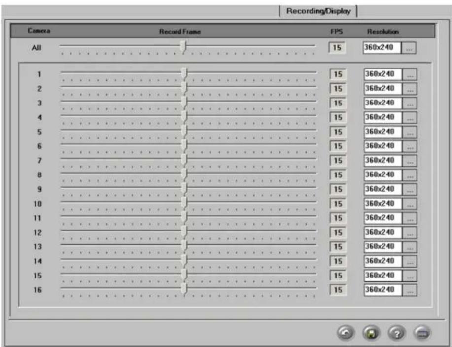
To set up Recording/Display, do the following:
- Configure the Record Frame, frames per second (FPS) rate for each analog camera. Note that these settings apply on per camera and not per channel basis. The configured recording fps rate will also
-
Configure the Resolution for each camera. Three resolution options are available: 360x240, 720x240, and 720x480. The higher the resolution, the higher the quality of the video recording and the required for storage. Also note that with the higher resolution options, the total number of
-
Click Defaults to assign an average fps number of each camera
4.
Click the Save button to save the configured settings

Note
This setup tab affects recording and display frame rate for Mux Mode display).
frame rate display |Live

1.3.21. Virtual Ruler
1.3.21.1. Overview
With this feature it is possible to approximate the height of a person once they are in the camera's view. During playback, the person's height can be estimated with regard to the virtual ruler. (In the example below, the ruler is 6' long with a division value of 1'.)

Important
This feature is not supported with IP as.
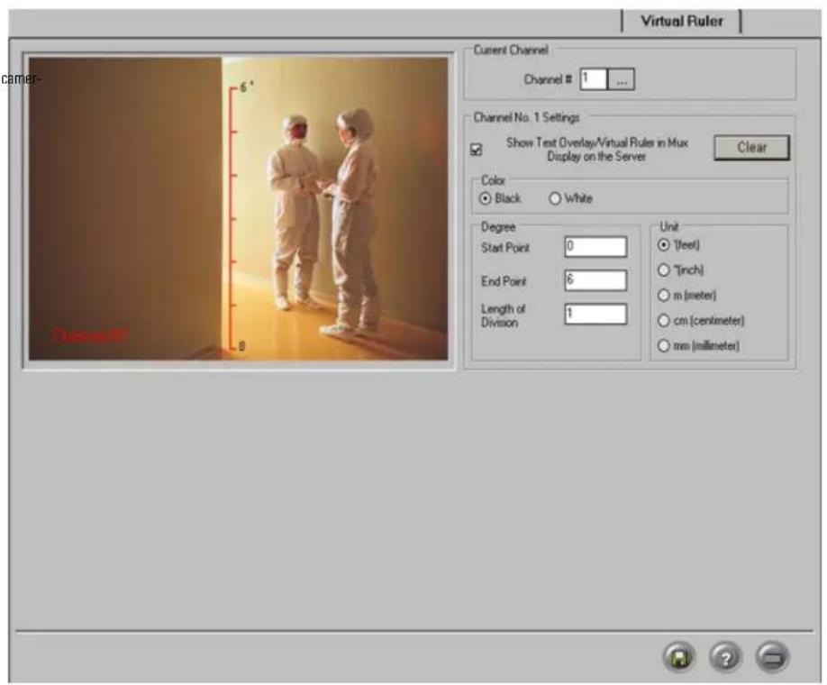
1.3.21.2. Configuring Virtual Ruler
To configure Virtual Ruler setup, do the following:
- Click the Browse button in the Channel # field to select the desired channel from the list. Only channels activated in the Hardware Setup tab will be displayed.
- Check Show Text Overlay/Virtual Ruler in Mux Display on the Server to Ruler in the live view window.
- Select the Color (Black or White) of the ruler that will be shown on the screen. Choose the color that will best contrast with the background.
- In the Degree frame, enter the Start Point value of the ruler. This number will be shown at the starting point of the ruler.
- In the Degree frame, enter the End Point value of the ruler. This number will be shown at the end point of the ruler.
-
In the Degree frame, enter the Length of Division value, which is the value of one ruler division. This number has to be smaller than the length of the ruler, or will be assigned the same v. The division value is the distance (in chosen units: feet, meters, etc.) between two dividers. number of ruler divisions, the length of the ruler is divided by the Length of Division val
-
The smaller the division value, the more divisions there will be on the ruler. The ELMO-PI adjust the division value if the length of the ruler can not be equally divided by the specified Length of Division value.

- In the Unit section, select the desired unit of measurement: feet, inches, meters, etc.
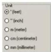
1.3.21.2.1. Drawing a Virtual Ruler
- Physically measure the height or the area covered in the camera view
- Draw a mark(s) on that area to signify the start and end points of the ruler
- Using the mouse, move the cursor to the live view window in the Virtual Ruler Setup 1
- Hold down the left mouse button, and drag it in a straight line
- Adjust or move the ruler if necessary
- To erase the ruler click Clear
Example,
For example, the height of the door entrance is exactly 84 inches. The ruler starts with 0 (floor) and ends with 84" Itop of the entrance). The unit of measurement is inches. Originally, the Length of Division value er 84 cannot be equally divided by 10, and therefore the ELMO-PRO Server adjusted the value to 10.5. Therefore, 84"/10.5" = 8. The ruler is divided into 8 equal parts, with the value of one division equal to 10.
1.3.22. E-Mail Setup
This Setup tab allows the sending of an alert via email when a sensor is triggered, or when a video signal has been lost. It can also send the status of the Server by sending a screen shot from a specified channel

There are three ways to send an email alert:
1. Triggered Sensor(s)
Select appropriate sensors in the Enable Email For Sensor frame. Whenever any of the selected sensors are triggered, an e-mail alert will be sent to the configured e-mail address.
2. Video Loss
Check the Video Loss checkbox in the Enable Email for Video Loss frame. When video loss is detected on one or more channels, an e-mail alert will be sent to the configured e-mail address.

Tip
Make sure the sensors are enabled and configured in the Hardware Setup.

3. Scheduled Server Status
This section allows the user to configure scheduled e-mails to provide the server status. The from the specified channel. To have the DVR send server status e-mails, fill in Server Status section:
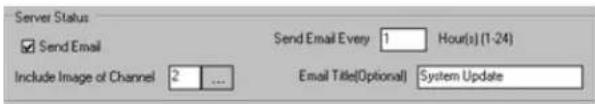
a. Check the Send Email checkbox to enable server status e-mail alerts
b. Select the frequency of the automatic e-mails (1-24 hours) in the Send Email Every field. In the example above, the server status email will be sent out every hour.
C. In the Include Image of Channel field, click the Browse button to select the desired channel from the list. A snapshot from this channel will be sent out. In the example above, s be sent out every hour to the configured email address.
d. Enter the Email Title for the server status e-mail alerts (Optional).

Note
A first e-mail is sent after changes to this setting are saved and on the ELMO-PRO Server startup. The ELMO-PRO Server will then send e-mails according to the set schedule. In the above example, every hour.
1.3.22.1. Configuring Email Setup
-
Check the Enable Email checkbox to enable Email feature.
-
Fill in the Send To section:

- Enter the Email Address of the recipient
- Enter the Threshold number. This value refers to the total number of emails sent when a sensor is triggered, video loss is detected or motion is detected.
- Fill in the Send From section:

- Enter the Name of the sender (Optional)
- Enter the Email Address of the sender
- Fill in the SMTP Server section: Depending on the location, each Internet provider has specific SMTP information. Obtain this information from your Internet provider.

a. Enter the IP Address of the SMTP server. Ask your provider for SMTP server address.
b. Enter the Port number. It is not usually necessary to change the port number. Most SMTP servers have a default port. For more information on default Ports, contact the email account manager.
c. Select the Login Method. "None" is the default method; otherwise, contact the email account manager.
d. Enter the User Name and Password: Some Internet providers require user names and passwords to send out emails, if this is the case, enter them accordingly.
5. Enter the Email Transmission Delay. This option sets the amount of time that will pass before email transmission.
Related Topics: Hardware Setup-Sensor Settings
1.4. Search and Playback on ELMO-Server
Search is one of ELMO-PRO Server's most used features. DVR technology provides an instantaneous time/date/channel and object search - an exclusive feature not offered by VCR technology. Effective capabilities make DVR technology much more efficient as it eliminates hours of video screening - common with conventional VCR technology.
Search and Playback is available from both Search and Live modes.
1.4.1. Video Search and Playback in Live
ELMO-PRO software allows the user to search the specific channel(s) in the Live Mode view. The search on the selected channel(s), while monitoring the remaining channels in the Live Mode. On be performed individually for each camera, i.e. the start playback time can be different for each
To playback recorded video in Live Mode, do the following:
-
Right-click on the desired channel in the Live Mode
-
Select the Search Mode from the context menu
![Search Mode Channel #1 [Channel 1]](/content/2026/06/1226295/images/1fc3c7df7efdb90a32340344692dd3cd4bc826f2ee289d36b84f386a555ff3af.jpg)
-
Repeat steps 1 and 2 for all desired channels
-
The 24-hour timeline with control buttons will be displayed for selected channels. This 24-hour timeline is similar to the 24-hour timeline in Search Window. Live Mode, however, only allows searching within a Search Mode to search outside of the current calendar day. To move the timeline on the over the channel number, left-click and hold the mouse button, while moving the timeline to
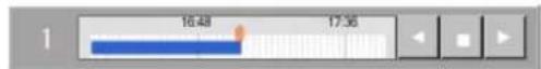
The timeline with recorded audio will look as follows. The purple line underneath the blue video recording bar represents the audio recording. The audio recording can only be played back in the Search mode. See Mode section.

- Timeline is expanded by default to simplify search. To zoom out of the timeline, right-click on the timeline and select Zoom Out from the context menu; repeat to zoom out twice.

- To playback the recorded video using the timeline, do the following:
a. Position the red timeline marker at the playback start time
b. To start/resume playback, click the Play button ▶. Click again to increase the playback speed. Available speeds: 1X, 2X, 16X
c. To stop playback, click the Stop button
d. To reverse playback, click the Reverse button. Click again to increase the playback speed. Available speeds: 1X, -2X, -16X
- To return to the live mode, do the following:
a. Right-click on the desired camera in the Search Mode
b. Select the Live Mode in the context menu
c. Repeat steps 1 and 2 for all desired cameras

The exact time will be displayed inside the timeline on the mouse cursor roll-over. Note that the roll-over time is displayed for the mouse cursor and not the red timeline marker. In the example below, the red timeli 5:20 AM, while the mouse cursor is pointed at 12:00 PM. The roll-over time displayed inside PM.
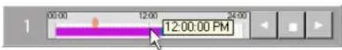
1.4.2. Video Search and Playback in Searc Mode
The main areas of the Search window are:
- Display window
- Screen Division panel
- Time Panel
- Tools panel
- Other Features: Advanced Search panel / Image Settings panel
- Playback control panel
- Channel selection for search
- 24-hour timeline
- Current Time/Date
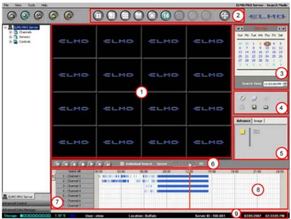
1.4.2.1. Screen Division Panel

natural_image
Row of grayscale circular icons with grid and circle patterns, no text or symbols visibleUse the screen division panel the same way as on the Main Screen to switch between 4, sions.
Use the Full Screen button to display a single channel, selected screen division or still image in the full screen mode with no Graphic User Interface (GUI)
1.4.2.2. Time Panel

Time
Browse through the 24 hour clock by scrolling the arrows up and down. Adjust this menu will move the time line marker on the timeline bar.
In this example: the time line marker in the timeline bar is set to
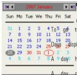
previous/next month, click on the arrows:
to the first/last recorded date, click on the arrows:
played in red are days for which there is recorded data.
highlighted in grey indicates a day selected for a search
circled with a red oval indicates the current day of recording
In this example: There is recorded video data on January 25th - 28th 30th - February 1st, 2007. Video Recording for January 28th is currently disp day of the video recording is February 1st, 2007.
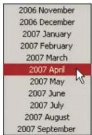
To quickly access specific month within one calendar year, click on the month window and select the desired month. The calendar will display the selected
1.4.2.3. Channel Activation Buttons
Channel Activation Buttons allow choosing specific channels for each search. To select a channel Channel Activation Button. The video recording area associated with this channel will be highlighted in blue. Click Select All to select all channels.
1.4.2.4. 24-hour Timeline
Timeline provides a visual representation of the recorded video data. The recorded data is represented by bars. The color of the bar indicates the type of the video recording (motion, sensor, continuous)
The timeline bar permits navigating through recordings made with different channels and browsing clock.
This timeline represents a single day chosen in the Calendar. Timeline can be expanded to sim the 24-hour time line. A context window will appear.
Choose Zoom In to expand the time line bar or Zoom Out to collapse the time line bar.
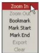

When expanded, the Timeline bar has both vertical and horizontal scroll bars. The vertical is us available Channel Activation Buttons, the horizontal scroll bar is added to browse through the ex
Timeline (normal)
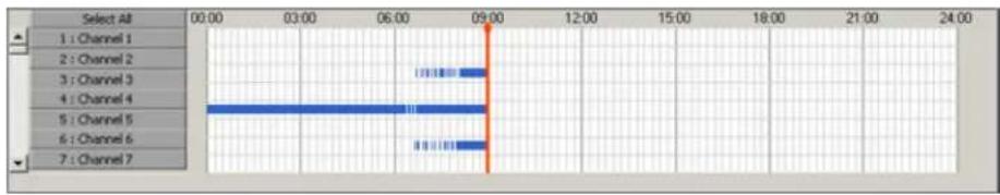
Timeline (zoom in)
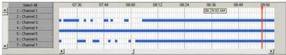
1.4.2.4.1. Channel Scroll Bar
Scroll up and down to see all available Channel Activation Buttons
1.4.2.4.2. Timeline Marker
The red line inside the 24-hour Timeline is the Timeline marker that indicates the playback sta above, the Timeline marker is set to 8:58.
1.4.2.4.3. Video Recording Bars and Types of Recording
Multicolored bars represent different types of recording.
- the pink bar indicates Continuous Recording (Channel 1 is recording based on Continuous rec
- the orange bar indicates Sensor Recording |Channel 2 is recording based on Sensor recording
- the blue bar indicates Motion Recording (Channel 3 is recording based on Motion recording
- the green bar indicates Sensor + Motion Recording |Channel 4 is recording based on Sensor schedule

1.4.2.5. Switching to Daylight Saving Time
Setting the time forward one hour will cause no system confusion. The particular hour jumped from the timeline. However, a problem may occur when the time is moved back one hour in the system will have to overwrite the previously recorded hour of information. As a result, valuable information could be lost, which is why the System time in the ELMO-PRO Server can be set forward only.
In order to avoid the loss of information, a 25th hour is added when the Daylight Saving Time ends in the Fall and clocks are set back an hour. This method of time adjustment prevents the loss of video data and does not "confuse" the system.
I.e: With this method, the timeline will have two instances of '1:00am.' This way, the video data will not be lost or recorded over, while system time stays correct and up-to-date. Zoom in the timeline to see the time.
1.4.2.6. Playback Control Panel
Playback buttons are located on the bottom of the Search Window.

Skip to the beginning of the recorded data
View previous frame
Reverse playback
Stop
Play
View next frame
Skip to the end of the recorded data
Individual Search - check off to select a different start playback time for different
Speed - By adjusting the Speed scrollbar, configure the speed of playback. By default, the video is played back at a regular (1X) speed. To increase the playback speed, drag the scrollbar to the right, to reduce the scrollbar to the left.
Available playback speeds: -6X, -5X, -4X, -2X, 1X, 2X, 4X, 8X, 16X, 32X
The Tools panel contains the following function buttons:

Refresh. Click the Refresh button to refresh the timeline to display the recently recorded video.

Panorama. Click the Panorama button to view the video segment frame-by-frame in the multiple screen division

Resize. Double click the desired channel to make it full screen and click the Resize button to enlarge the image to fit the display window

Print. Click the Print button to print the still image on the connected printer.

Backup. Click the Backup button to save the video/still image on to local or remote media.

Bookmark. Click the Bookmark button to save the exact time of the video recording, so that it can be quickly located on the timeline later.

Audio Setup. Click the Audio Setup button to mute/adjust the audio volume.

- Zoom In / Zoom Out / Drag. Click the Zoom button to switch between the Zoom In, Zoom Out and Drag functions. The user can right click in the full screen channel's image image and drag the enlarged image on the display screen.
1.4.2.8. Audio Recording in Search Mode
Note that audio is recorded simultaneously with the video, i.e. when the video is not being recorded, the associated audio channel is not being recorded either.

Important
The audio recording can only be in the Search Mode.
To play back specific audio channel, do the following:
played back
- Access the Search Mode. The audio recording is represented by a thin purple bar underneath
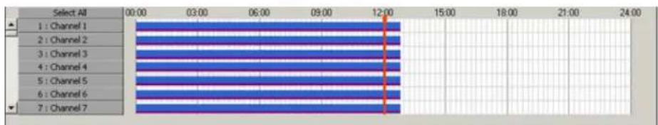
- Check off the Individual Search checkbox to display audio activation icons as shown bel


Tip
Only one audio channel can be played at given time. In order to listen to the audio recording along with the corresponding video recording, the desired audio channel must be selected before starting the video playback.
- To select the audio channel for playback, click on the audio icon next to the corresponding icon for the selected audio channel will turn red. In the example below, audio on video at any audition.
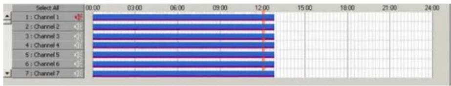
- Select the corresponding video channel.
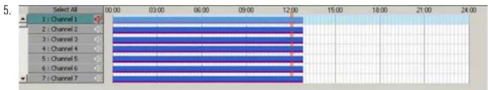
- Click the button on the control panel to initiate video and audio playback.
1.4.3. Video Playback in Search Mode
To playback the video recording in the Search mode, do the following:
-
Choose the date from the Calendar
-
Set the start time of the recording in the Search Time
OR
Set the time of the recording by clicking inside of the timeline bar to set the timeline marker (the vertical red line) to the start of the video recording to be played.
- Choose one or more channels in the Timeline bar by clicking on the appropriate channel activation buttons.
If no channels are chosen for the search, the following warning window will appear:
-
To start the playback, click the Play button
-
To view a single channel in a 1-channel screen, double-click the desired channel, resume play
-
To go back to the multiple-channels screen division, double-click the display screen, and resume
-
Individual Search allows users to select a different time for different channels for play back. Set the time for each channel by clicking inside of the timeline bar of each channel.
1.4.4. Video Playback from Advanced Data Manager
The Advanced Data Manager allows the user to playback previously created backup files (Encrypted backup image files (BMP or JPG).
To access the Advanced Data Manager (ADM), do the following:
-
Click Advanced Data Manager panel (located in the Control Center) to expand it. ELMO-PRO must be in either Advanced or Tree View.
-
In the Advanced Data Manager panel, locate and expand the Backup folder. A list of all *.bmp and *.jpg will be displayed.
-
To open any backup file, double-click on it.
a. *.i3d files will open in the Search Window.
In the top right corner of the Main Screen, the current status will become Server - E ELMO PRO Server - Backup Viewer Search Mode
To return to the Search mode, click Close Backup Viewer
b. *.avi files will open in Windows Media Player
c. *.bmp and *.jpg files will open in Windows Picture and Fax Viewer
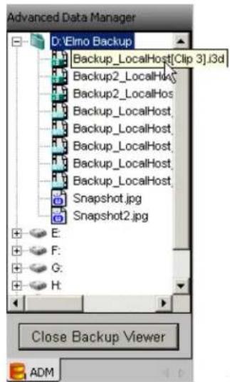
1.4.5. Using Bookmark
Much like regular paper bookmarks, bookmarks in the Server Search mode are used to mark a video recording for quick access at a later time. The Bookmark function saves the date and instance in a single database, to simplify the search process later on.

Important
The existing bookmarks only exist as the corresponding video record on the hard drive(s). Once the ing is overwritten, the bookmark works. For details on how to video from being overwritten, see Setup section.
To use the bookmark, do the following:
as long 1. Select the date of the recording in the Calendar gs exist video record Set the start time in the Search Time window or by clicking directly on the timeline no longer prevent and Storace: Choose one or more channels in the Timeline bar by clicking on the appropriate channel activation buttons.
- Right-click inside the time panel and select Bookmark in the context window OR
Click the Bookmark button on the Tools panel
- Click Add in the Bookmark window. The set time, date, selected channels will be added automatically to the bookmark database.
a. Enter the Bookmark description. E.g. "Monday Evening"

On the timeline, the bookmarks are clearly marked with the green triangle. When cursor the bookmark time and name are displayed.

- To jump to the bookmarked location on the time line, click the Click the Bookmark button on the Tools panel
and double-click the bookmark entry in the Bookmark window, or double-click the green line bar area. The red time line marker will jump to the specified bookmarked time on tl
-
To delete a bookmark, select bookmark item in the Bookmark window and click Delete
-
To delete all bookmarks, click Delete All
-
To close the Bookmark window, click Close
1.4.6. Panorama function
The Panorama function can be used to view the video recording frame-by-frame in the selected be done to see the motion progression, count the number of frames in a second, etc.
To use the Panorama function, do the following:
-
Click the Panorama button on the Tools panel
-
Select a channel
-
Set the start time in the Search Time window or by clicking directly on the timeline
-
Select the desired screen division: 4, 6, 9, 10, 13 or 16 by clicking on the corresponding buttons on the Screen Division panel.
-
Start playback by clicking the Play button
OR
Click the Next Frame button to display each consequent frame in the next screen divisio
In the example below, Channel #2 is displayed on nine screens in the 9-screen division Panorama mode. The Screen division shows 9 consequent frames starting at 08:52:24 {frame#1} and ending at 08:52:24 {frame#9} on


Note
These instructions apply to paused ages
1.4.7. Image Zoom In/Zoom Out
To zoom in/zoom out/drag enlarged image, do the following:
im-1. Select the channel
-
Set the start time in the Search Time window or by clicking directly on the timeline
-
Start playback
-
Double click the desired channel to display it separately in the display window
-
For a still image, stop the video recording by clicking the Stop button in the Playback Control panel
-
On the Tools panel select the plus sign to zoom in, or minus sign to zoom out
To switch between zoom in/zoom out and drag buttons, click the Zoom button on the T
-
Right-click the still image to zoom in/out until the desired result is achieved. The image can be zoomed in digitally up to 18 times. Digital zoom refers to the pixilation of an image. This is not the same as capacity to zoom in on a picture. Digital zoom changes the size of the image without aff
-
To drag the enlarged image, choose the Drag button on the Tools panel, click the image, hold down the right mouse button and drag the image
1.4.8. Advanced Search Panel
The Advanced search panel allows Index Search and Object Search of the recorded video data.
Index Search/Object Search

Search
Search
1.4.8.1. Index Search Panel
Click the Hide/Show Index Search panel button to bring up the Search Option panel.
The Index Search panel allows the users to distinguish between different types of recording and the specific frames, where detected motion, or triggered sensor recording took place.
Index Search is used to search a recorded video using the recording type: motion, sensor or
To search the available video recording based on Sensor or Motion, do the
1.
Click the Index Search panel button
-
Select the day in the Calendar. Index Search will search all available video recordings starting from 00:00:00 to 23:59:59 of the same day.
-
When in index search mode,
a.
Select Continuous Search to view all video recorded continuously
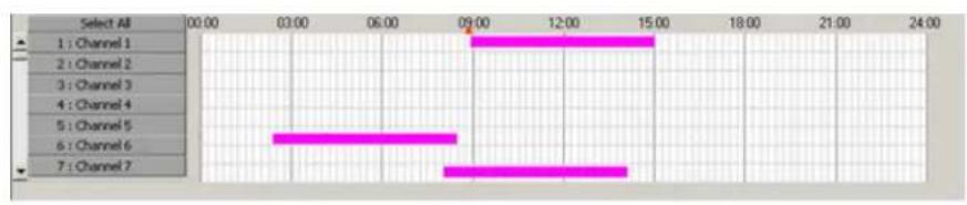
b.
Select Sensor Search to view all video recorded when sensors were triggered
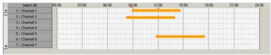
This information can be further filtered by selecting:
i. Switch to Search by Sensor:
A. The first column will display all the sensors triggered. In this example, Sensors 1
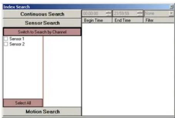
B. Select any sensor to further filter the recorded video data and to display only th based on Sensor 1 activation. In this example, channels 2,3,7 and 9 recorded when
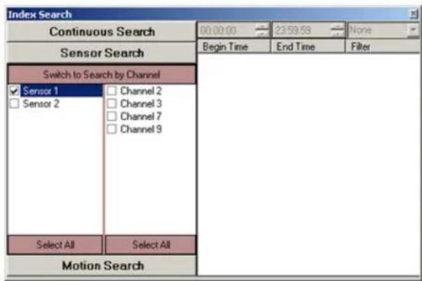
C. Select any channel to view more details about the sensor triggered (Begin Time, E

D. Recorded data can be further filtered by narrowing the time range. The filter colour number.

Note
An Index Search can only be performed within one calendar day.
ii. Switch to Search by Channel:
A. The first column will display all 24 channels
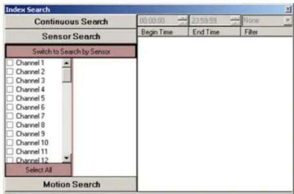
B. Select any channel(s) to view which sensor(s) triggered the video recording for the this example, Channel 9 was recording based on Sensor 1 and Sensor 2 activation.
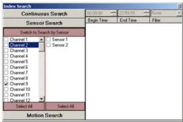
C. Select any sensor to view more details (Begin Time, End Time and Filter). In this 2 were selected. Both were associated with channel 9
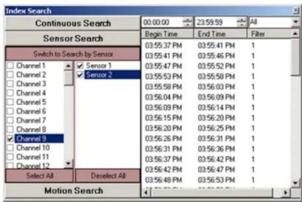
D. Recorded data can be further filtered by narrowing the time range. The filter colour number.

Note
An Index Search can only be performed within one calendar day.
C. Select Motion Search to view all video recorded when motion was detected
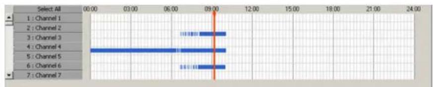
This information can be further filtered by selecting:
i. Switch to Search by Motion:
A. The first column will display all motion areas associated with specific channels, where motion was detected. In this example, motion was detected in Area 1 of Channels 7,11 and 12

B. Select any motion area to view the associated video channel

C. Select any channel to view more details (Begin Time, End Time and Filter)
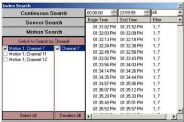
D. Recorded data can be further filtered by narrowing the time range. The filter colour number.

Note
An Index Search can only be performed within one calendar day.
ii. Switch to Search by Channel:
A. The first column will display 24 channels

B. Select any channel to view the areas triggered with motion

C. Select a motion area associated with a channel to view more details |Begin Time,

D. Recorded data can be further filtered by narrowing the time range. The filter colour number.

Note
An Index Search can only be performed within one calendar day.
- To view a specific frame, click the desired frame on the right-most panel in the index s frame will be displayed in the search timeline bar.

Note
An Object Search can only be one channel at a time within period.
1.4.8.2. Object Search
The Object Search function allows searching for a change in the highlighted area.
performed To use Object Search, do the following:
- Selected the desired day of video recording in the calendar window.
- Choose the channel in the Channel Activation Button bar for an Object Search
- Double-click the video image of the channel, to display selected channel in full-screen mode.
- Click the Object Search button in the Advanced Search panel. Object Search window will be displayed over the Control Center:
![Object Search Start Time 03:17:00 PM End Time 03:18:00 PM Interval 1 Second ... Display Thumbnails ... Start Pause [15:17.09] [15:17.14] [15:17.19]](/content/2026/06/1226295/images/fc38a4d48c17f56625d392bfcf9c30ccbcd1eab6bdb01f1d2c48be031739a71c.jpg)
- Define the detection area:
a. Place the cursor over the start point on the live view window
b. Hold the left mouse button down and drag to create a rectangular area
c. Let the mouse button go
d. Move/adjust the area if necessary
e. To delete a specific detection area, select the area by clicking on it, hold down the the area to remove it from the live view screen. If no area is selected, the following error message will appear. A maximum of 8 detection

- Set the Start Time and the End Time. Only the selected part of the video recording will be processed by Object Search. Remember that the Start/End time pertain to the day selected in the calendar
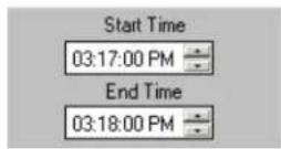
- Set the Interval. Available intervals: 1 second, 30 seconds, 1 minute, 5 minutes, 10 minutes, 15 minutes, 20 minutes, 30 minutes, 1 hour. The Object Search will be conducted based on the selected time interval. E.g. If 30 seconds interval is selected, Object Search v 30 seconds within the set time frame. This means that provided video has been recorded; only one out of 9000 frames will be checked for motion (30 seconds x 30 frames).
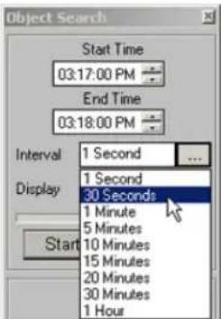
- Select the Display between Thumbnails and Text.
In both cases, the motion detection instance will have the time stamp displayed. To view screen, left click either the image thumbnail (example on the left) or the text line (example
![Object Search Start Time 03:17:00 PM End Time 03:18:00 PM Interval 1 Second ... Display Thumbnails ... Start Pause [15:17:09] [15:17:14] [15:17:19]](/content/2026/06/1226295/images/9bc788defcd2a5596796ab20f8179df67f90300185b4478145d0d9718d7d47f6.jpg)
![Object Search Start Time 03:17:00 PM End Time 03:18:00 PM Interval 1 Second ... Display Text ... Start Pause [15:17.09] Object Detected [15:17.14] Object Detected [15:17.19] Object Detected [15:17.24] Object Detected [15:17.29] Object Detected [15:17.34] Object Detected [15:17.39] Object Detected [15:17.44] Object Detected [15:17.49] Object Detected [15:17.54] Object Detected [15:17.59] Object Detected](/content/2026/06/1226295/images/bc485dbe5461f0f6541d3c3709b5707f986fb71a5f2d7d873f48ce2e1b92b3e2.jpg)
-
Click Start in the Object Search window to start.
-
In the Object Search window, browse through the found instances.
11.

Click the Object Search button again to hide Object Search window search in the Advanced Search panel or click the Close button (x) in the top right corner of the Object Search window to close it.
1.4.9. Image Settings Panel
The Image Settings panel is for editing still images. The edited image can then be printed on media.
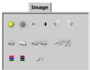
natural_image
Grid of grayscale icons representing weather and objects (no text or symbols)To enable the Image Settings panel, do the following:
- Select the channel
- Set the start time by clicking directly on the timeline
- Start the playback
-
Stop the playback at the exact frame
-
Click the desired channel to show it separately in the display window. The Image Setting

Brightness. Click the right (left) icon to increase (decrease) image brightness.

Contrast. Click the right (left) icon to increase (decrease) image contrast.

Sharpness. Click the right (left) icon to increase (decrease) image sharpness.

Noise Reduction. Click the icon to reduce the noise in the image

Deskew. Images may sometimes be off-centered by a few degrees. The Deskew option is used to correct such skews. Click the right (left) icon to rotate the image clockwise (counterclockwise).

Gamma correction. Click the right (left) icon to decrease (increase) the gamma correction input. This is done in order to display the image colors correctly by customizing the gamma corr output. The lower the gamma correction input the lighter the image.

Rotation. Click the icon to rotate the image clockwise by 90^ and to flip it vertically or horizontally.

Undo. Click the icon to undo all the changes and to return to the original image
1.5. Backup on ELMO-PRO Server
ELMO-PRO allows the user to backup data from the hard drive to the local drive or CD-R/DV format. The backup files can be later opened from the Advanced Data Manager
AVI: allows saving multiple cameras at a time, however, each video channel is saved in a separate file. During playback, the files will be opened with any Windows media player – one-at-a-time. This type of video additional software and can be opened on any PC that operates on Windows O/S.
Encrypted (default): allows saving multiple cameras in a single backup file. The saved encrypted backup file can be opened with ELMO-PRO software (Advanced Data Manager) or with ELMO-PRO Player, all save played back at the same time in the selected screen division.
1.5.1. Quick CD Backup in Live Mode
Quick Backup allows saving a portion of the video recording from the hard drive to a CD-R/I
To perform a quick CD backup in Live Mode, do the following:
-
Right-click on the desired camera in the Live Mode
-
Select Search Mode in the context menu
-
Position the mouse cursor over the desired start time on the timeline
-
Right-click on the timeline and select Mark Start in the context menu. In the example below, the start time is 11:42:00 AM. The start time will be marked with the broken green line.

-
Position the mouse cursor over the desired end time.
-
Right-click on the timeline and select Mark End in the context menu. In the example below, the end time is 11:46:00 AM. The end time will be marked with the broken red line.
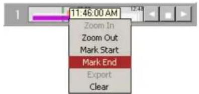
- Right-click on the timeline and select Export in the context menu to proceed with the backup. To clear the Start and End Times for quick backup, select Clear in the context menu.
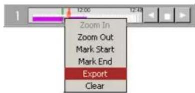
- The following message window will appear. Click OK to close it. The backup session has now been saved to the backup list. Please refer to Completing Backup section for more information.

1.5.2. Quick CD Backup in Search Mode
Quick Backup allows saving a portion of the video recording from the hard drive to a CD-R/I
To perform a quick CD backup in Search Mode, do the following:
- Ensure that there is enough free space on the C drive - at least 650 MB should be
2.
Click the Search button to access the Search mode.
-
Select one or more channels by clicking on appropriate channel selection buttons.
-
Set the start time in the Calendar window or by clicking directly on the timeline.
-
Right-click inside the 24-hour timeline. The context menu will appear. Select Mark Start to choose the start time. Start time on the timeline will be marked with the broken green line.
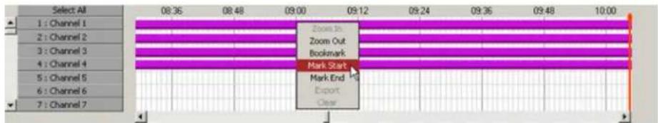
- Right-click inside the 24-hour timeline, where the backup recording should end. The context n Mark End to choose the end time. End time on the timeline will be marked with the broken red line and the video segment between Start and End time lines will be grayed out.

- Right-click on the highlighted video segment. The context menu will appear. Select Export to save the backup session to the Backup menu.
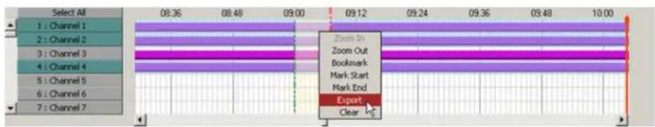
- The following message window will appear. Click OK to close it. The backup session has now been saved to the backup list. Please refer to Completing Backup section for more information.
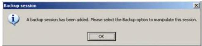
1.5.3. Backup Window
To view, edit or complete backup session(s), do the following:
- Select Backup in the Tools menu (if in Live Model)
OR
Click Backup button in the Tools panel (if in Search Model)
- A new window will appear:

In the Backup window, all backup clips are saved pending the user action. The saved backup edited, deleted or finalized. Additionally, the new backup clips may be created in the Backup v
The following backup parameters may be edited for each existing backup
- Destination: CD/DVD (default for Quick CD Backup); Local Storage (local/network/removable drive, USB); Email
- Start and End Date/Time
- Channels
- Format: AVI (default for Quick CD Backup); Encrypted
- AVI Embed Text
! Important
To save any changes to the s clip, click Update in the bottom dow.
i Tip
To perform any action, the clip checkmarked in the list.
selected backup
of the win


Add a new backup session. Adds a new backup clip based on the configured S
Delete selected backup session(s).
Start creating a new backup file. Starts the backup for the selected backup clips
Stop creating a complete backup file. Interrupts the backup session already in prog
1.5.3.1. Completing (Quick CD) Video Backup Sessio
All quick CD backup sessions will be saved in the Backup window until completed by the us quick CD backup sessions are saved in AVI format.
In order to proceed with the CD-R/DVD-R backup, do the following:
- Insert the CD-R/DVD-R into the combo drive
- Checkmark all backup clips that will be saved onto the CD-R/DVD-R
- Click the Start Backup button
- Wait until the status changes from Ready to Finished for all selected clips
- Remove CD-R/DVD-R from combo drive
1.5.3.2. Interrupting Video Backup Session In Progre
It is possible to interrupt the backup session in progress. To stop the active backup session, checkmark the desired session
in the list and click the StopStopbutton .
The following warning window will be displayed.
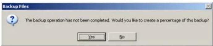
Click Yes to save the completed percentage of the backup session. When Yes is clicked, the video backup that has been created before termination will be saved as a separate file.
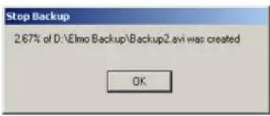
When No is clicked, no backup files will be created
1.5.3.3. Creating New Video Backup Session
New backup sessions can be created directly from the Backup window.
To create a brand new backup session, do the following:
- Set the video backup start date and time from the Start Date/Time menu
- Set the video backup end date and time from the End Date/Time menu
- Click the Channels -> Channels tab and select video channels to back up. To select a video channel, double-in click on the corresponding checkbox. Only channels activated in the Hardware Setup tab will Select All to select all available video channels.
- Click the Channels -> Video Settings tab to choose the backup video format from ELMO Compression (default) and AVI.
Creating AVI Backup session:
a. Select AVI radio button
b. Select AVI video codec from the list.
Attention: It is highly advisable to leave the default codec chosen by the Server - it is always the latest available codec. In this example, Microsoft MPEG-4 Video Codec V2I. The only reason to earlier version would be to allow the playback of an AVI backup file on older systems
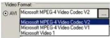
c. Click the AVI Text Embedding tab
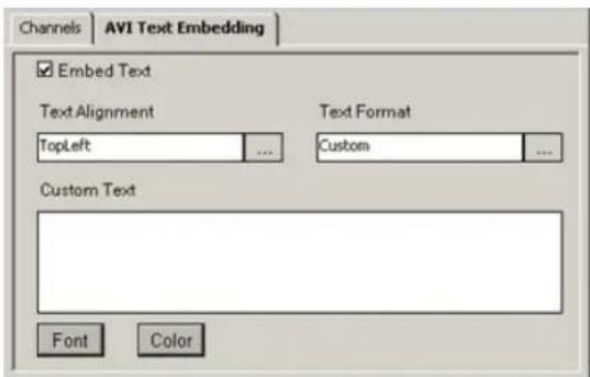
i. Check the Embed Text checkbox
ii. Select the desired Text Format for the AVI file. Browse from the list of all availab will be overlaid on the AVI video.
![Text Format Custom [Server][Channel][Time][Frame] [Server][Time][Frame] [Server][Time] [Channel][Time][Frame] [Channel][Time] [Channel] [Time][Frame] [Time]](/content/2026/06/1226295/images/707c3722df0101d08230f8e5b0634a62ed37d4d21507f49d5ca72692dde2f5e8.jpg)
iii. Select the position for the AVI caption from the list. Browse the list of caption point to termine the location of the Caption text overlay on the video.

iv. For custom text, enter text in the Custom Text field. Click Font and Color to format this text.

Creating Encrypted Backup session:
a. Select the ELMO Compression radio button
- Click the Browse button in the Destination field to select between Local Storage, CD/DVD and Email.
a. Saving to the local storage. The recording will be saved to the selected local/network/removable drive.

i. Click the Browse button in the destination path to select the local/network/removable
ii. Locate the desired drive and folder on the chosen drive
iii. Enter the backup file name
iv. Click Save
![Backup File Name Save in: Elmo Backup Backup2_LocalHost[Clip 1].i3d Backup2_LocalHost[Clip 2].i3d Backup_LocalHost[Clip 3].i3d Backup2_LocalHost_ch01[Clip 2]_Part1[360x240x1fps].avi Backup2_LocalHost_ch02[Clip 2]_Part1[360x240x7fps].avi Backup2_LocalHost_ch03[Clip 2]_Part1[360x240x7fps].avi Backup_LocalHo Backup_LocalHo Backup_LocalHo Backup_LocalHo Backup_LocalHo File name: Backup2.avi Save as type: AVI video files (*.avi) Save Cancel](/content/2026/06/1226295/images/abb6028b3deeca96ebcbaca0ed3da703d31d57f4247ff1ab868c44e0c6f8388a.jpg)
- Choose the Destination on Incident Properties field. The backup file can be saved to the local drive, CD/DVD or sent to an Email
a. Saving to the local drive. The recording will be saved to the Local Drive. Browse until the desired location is found
i. Select the Local Storage to save the video recording to a local drive
ii. Select Directory Path to save the video recording to any local drive
iii. Select the desired folder
iv. Click Save
b. Saving to CD/DVD. The recording will be saved to the CD/DVD.
i. Select CD/DVD to save the video recording to a CD/DVD drive

ii. Set the Number of Copies
Note that an ELMO-PRO Player will be added to your encrypted backup and the autorun your CD/DVD media. Please see ELMO-PRO Player section for more information.
c. Sending to Email. The recording will be sent to an email address.
i. Select E-Mail to send the video recording to an email address
ii. The E-Mail Address of recipient is loaded from the Email Address in the Send To section in Email setup tab

Note
Only AVI backup can be sent by email. Since
a typical provider limits the size of incoming email messages, Email backup is allowed for 1 channel at-a-time only. The length of the backup recording is set, by default, to 1 minute. For feature to work, the Email
setup tab must be correctly configured.
- Click the Add button to add created backup clip to the list of Backup Sessions Since
- To complete the backup session, check the checkbox(es) for the desired backup clip(s) and i
- To terminate an active backup session before completion, check the checkbox(es) for the desi
-
click the Stop button
-
To delete the backup session from the list, check the checkbox(es) for the desired backup clip(s) and click the Delete
button × Delete
1.5.4. Snapshot Backup
Snapshot backup allows the user to save a single frame as a still image on any local drive formats
To perform snapshot backup, do the following:
- In the Search mode, select the camera for playback.
- Double-click on the selected camera to display it in the full-screen mode in the live view
- Click the Play button on the Playback Control panel.
- Click the Stop button on the Playback Control panel to stop playback at the desired fran
- Click the Backup button in the Tools panel. The following screen will be displayed.
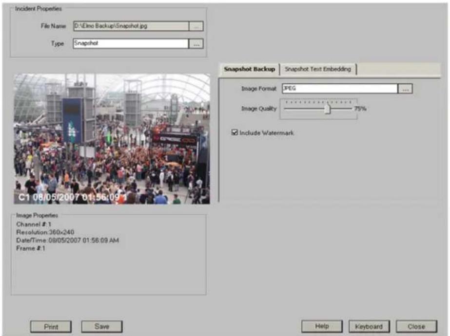
In the Snapshot Backup window, the user can:
- Change the file name and backup destination folder.
To change the file name, click the Browse button in the File Name field. Select the destination folder and enter the desired file name.
- Change the snapshot format.
To change the snapshot format, click Browse button in the Image Format field. Choose BMP or JPEG format in the drop-down menu.
- Change image quality.
To change the image quality, adjust the Image Quality slider.
- Print the selected image.
To print the snapshot, click Print in the bottom of the window.
- Save the snapshot to the chosen destination.
To proceed with the snapshot backup, click Save in the bottom of the window.
- Create embedded text.
See AVI Embedded text section for more details.

Tip
The authenticity of each saved snapshot can be verified with Watermark Tool. Please see the Watermark Tool section for more information.
1.5.5. Scheduled Backup
Scheduled backup allows creating a schedule for a video recording.
-
Go to Tools -> Scheduled Backup menu. Scheduled Backup window will be displayed.
-
Click the Add button + Add to created a new scheduled backup session. Schedule Job window will be displayed.

-
In the Recording Settings tab, select the backup type in the Video Format frame between AVI and ELMO Compression. If scheduling AVI backup, click Setting for mode AVI codec settings.
-
For AVI backup file, configure AVI Embedded Text Settings tab
-
In the Recording Settings tab, select channel(s) for scheduled backup. Only selected channels will be backed up.
-
In the Recording Settings tab, select the destination for the scheduled backup.
-
In the Schedule Settings tab, select the Schedule Interval
a. Once
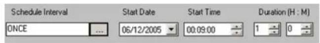
It will backup the data only once at the time selected on the Start Date, Start Time (H:M)
b. Day

Set Start Time and Duration(H:M). Select a specific day or check All Days. It will repeat the scheduled backup on the desired days for the selected number of months.
C. Week
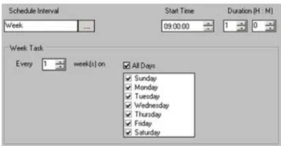
Set Start Time and Duration(H:M). Select the day or check All Days. It will repeat the scheduled backup on desired day(s) every selected number of weeks.
d. Month

Set Start Time and Duration(H:M). Select the day(s) in month(s) or check All Days or All Months
. It will repeat the scheduled backup for the desired day(s) for the selected month(s) o
- Click OK to add these scheduled backup settings or Cancel to ignore them. The added schedule will be displayed in the available scheduled jobs:

+ Add d a new scheduled backup session.
Edit t selected scheduled backup session.
✗ Delete ete existing scheduled backup session.
■ Stop terminate active scheduled backup session. Interrupts the scheduled backup session already in progress. Saves the created percentage of the backup.
Cancel ncel scheduled backup session. Do not create any backup files
2
ELMO-PRO Remote
Topics Covered
- ELMO-PRO Remote Setup
- Creating a New Connection
• Editing an Existing Remote Site Connection - Deleting a Remote Site
- Managing Sites
• ELMO-PRO Server Setup (via Remote)
• Viewing Video Channels via Remote
• Search on ELMO-PRO Remote
The ELMO-PRO Remote software is used to connect to and manage multiple servers by using. The managers can easily view the channels in the remote location, search the recording databases database. Most of the features provided in ELMO-PRO Server are available in ELMO-PRO Remote, products are not identical. The main difference between two applications is the fact that ELMO-I viewing video recording from more than one DVR.
The level of access assigned to the user in the ELMO-PRO Server remains the same, when I Remote. E.g. If the user is restricted from viewing Channel 1, they will not be able to see they log in with their name and password.
2.1. ELMO-PRO Remote Setup
Before connecting to the remote site, the user can configure the Display Mode used by ELMO
ELMO-PRO Remote Setup, disconnect from all connected sites and click the button .
The Remote Setup window will be displayed.
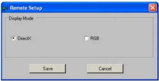
Select the desired Display Mode between DirectX and RGB. DirectX is the preferred and recommended display mode as it offers substantially higher quality video image. In cases, when DirectX is not installed on the system or is not available (is used by another program), select RGB display mode.
Usually, video cards with less than 64MB will not support DirectX.
2.2. Creating a New Connection
To create a new Server connection, do the following:
-
In the ELMO-PRO Control Center, click the Add/Edit Server icon . A new window will
-
Fill out the Add a new site window.
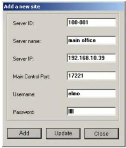

Caution
Ensure that the ELMO-PRO Server version installed on the remote DVR matches the ELMO PRO Remote version.
- Enter Server ID - This must match the remote Server ID as entered in the Server Information Setup.
-
Enter a Server Name - a descriptive name for the server. E.g. "main office"
-
Enter the Server IP address.
-
Enter the Main Control Port number. It must match with the number in Main Control Port in the Communication setup tab in the server
- Enter the User name and Password. When trying to connect to the remote server, the system will check the Server ID, User name and Password together. If either of the variables is incorrect, the be able to connect to the site
- Click Add to save the new connection or click Close to close the new site setup window without saving.
- When information for the new site is completed, it will appear in the Servers list.


Important
All connections added must have unique IP addresses. Servers with duplicate IP addresses will not be added.

Disconnected Server
Connected, inactive server
Connected, active server

Tip
The user may optionally update a previously added server, rather than add a completely new one.
2.3. Editing an Existing Remote Site Connection
To edit an existing remote site connection, do the following:
- In the Servers list, select the desired remote site
- Click the Add/Edit Server icon . A new window will be displayed.
- Make necessary changes in the Add a new site window and click Update

Important
The server MUST be disconnected fore any changes can be made.
from be-
2.4. Deleting a Remote Site
To delete a remote site from the list, do the following:
-
Select the remote site in the Servers list
-
Click on the Delete Server ✗ button
-
Click OK in the Delete Server window. The server will disappear from the Server list.
2.5. Managing Sites
2.5.1. Connecting to a Remote Site
To connect to the remote site, do the following:
- Select the desired remote site in the Servers list (ELMO-PRO Control Center)
- Click on the Connect to Server button or double-click on the selected server to connect. The Connection window will be displayed.
- If the connection is successful, the server icon will change from to or
- Repeat steps 1-2 for all desired remote sites.
2.5.2. Activating Connected Servers
Only one connected remote server is active at each given time.
To switch between connected remote servers, do the following:
specific 1. Select the desired inactive remote site in the Servers list.
- Right-click and select Active from the context menu. The server icon will change from to
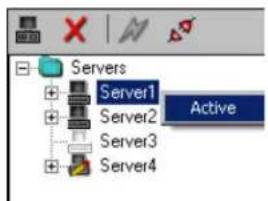
- To deactivate server, select the desired active remote site in the Servers list.
- Right-click and select Inactive from the context menu. The next connection on the list will become active
In the example above, ELMO-PRO Remote is connected to Servers 1, 2 and 4, while Server active server.
2.5.3. Disconnecting from a Remote Site
To disconnect from the remote site, do the following:
- Select the remote site in the Servers list.
- Click on the Disconnect Server button .
- The server icon will change from to or

Important
To search or configure setup for server it MUST be active
2.6. ELMO-PRO Server Setup (via Remote)

Warning
The ELMO-PRO Remote version MUST match the ELMO-PRO Server version.
The connected user can change most setup settings according to their level of access on the allowed setup tabs and features will be accessible based on user account. Certain setup features locally and are NOT available on ELMO-PRO Remote, such as editing/deleting user accounts or cl
To access the setup mode of the specific remote Server, do the followi
- Connect to the remote Server and ensure it is active. (See Activating Connected Servers for
2.
Click the Setup button
2.6.1. Remote Info Setup
The only setup tab present on ELMO-PRO Remote that is not available on ELMO-PRO Server is Remote Info setup tab.
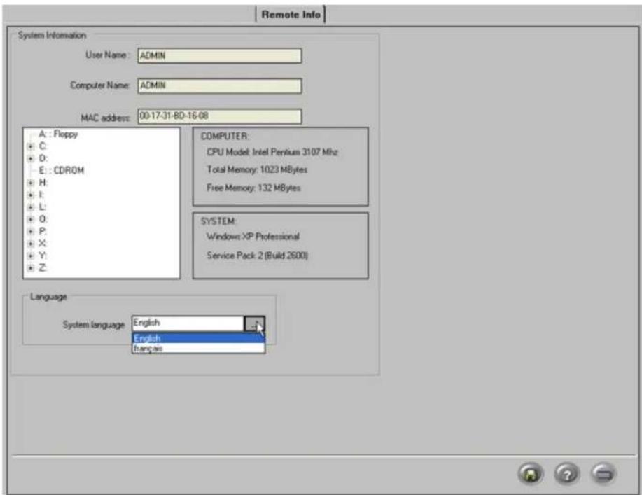
The Server Info Setup permits changing the ELMO-PRO Remote language, as well as obtaining in local computer, on which the ELMO-PRO Remote is installed.
System Information:
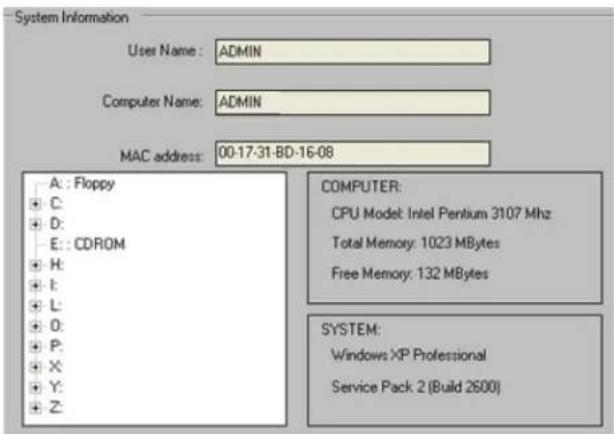
This section displays the following:
- User Name (User currently logged into the Local Computer)
- Local Computer Name
• MAC Address of the Local Computer
• CPU Model of the Local Computer - Windows operating system version installed on the Local Computer
• Service Pack version installed on the Local Computer
• List of drives/partitions of the Local Computer
• Total and free memory (RAM) information of the Local Computer
2.6.1.1. Language
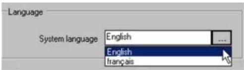
Two languages are currently supported on the ELMO-PRO Remote: English and French.
To change system language, select English or Français from the System Language drop-down menu. This will translate the ELMO-PRO Remote interface into the appropriate language.
Click the Save button to save the configured settings
2.7. Viewing Video Channels via Rer
With the ELMO-Pro Remote application, the user can access and view multiple video channels from remote sites. By using Drag-and-drop feature the user can select which channels from which remote servers will be displayed on their chosen screen division.
To view video channels from connected Server, do the following:
-
Expand the Channels list on the connected Server
-
Select one or more channels in the list.
To select multiple channels, press and hold Ctrl button on your keyboard, while selecting desired channels from the list.
To select all or a number of consecutive channels, click on the first desired channel, press and hold the Shift button on your keyboard and click on the last desired channel.
-
Hold the mouse cursor over selected channels, press and hold left mouse button
-
Drag the selected channels over to the ELMO-PRO Remote main screen and release the mo channels.
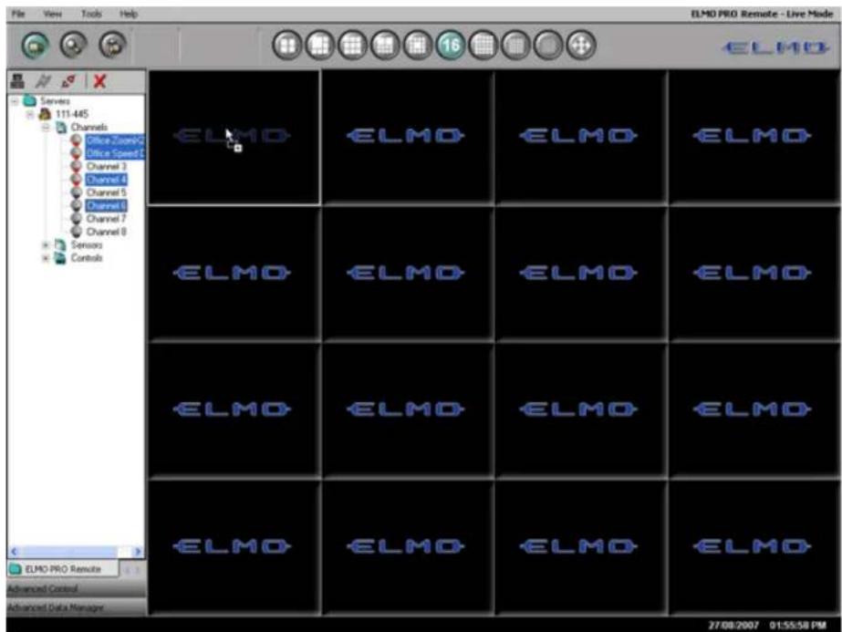
- Repeat steps 1-4 for all desired connected sites
2.8. Search on ELMO-PRO Remote
One of the main functions of ELMO-PRO Remote software is searching the video recordings stop Server (remote site). ELMO-PRO Remote software must be connected to a remote site before a performed. ELMO-PRO Remote software also allows searching data previously saved on the local n connected to any remote sites.
The remote search window on ELMO-PRO Remote is identical to the search window on the El following exceptions:
- In ELMO-PRO Remote, the user may switch between multiple connected remote sites (right-click and select Active).
The server must be active before a search can be performed.
- The channels must be dragged into the Choosing the channels to search data by dragging
2.8.1. Search on the Connected Site
To search a remote site, do the following:
- Connect to a desired remote site
2.
Click Search button on Main Screen
- Right-click an individual server and select Active to make it an active server. Search only may be performed on the connected, active servers.
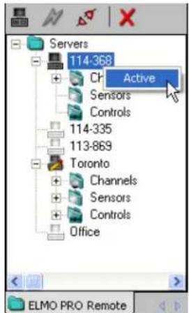
-
Expand the Channels list of the connected active Server
-
Select one or more channels in the list.
To select multiple channels, press and hold Ctrl button on your keyboard, while selecting desired channels from the list.
To select all or a number of consecutive channels, click on the first desired channel, press and hold the Shift button on your keyboard and click on the last desired channel.
-
Hold the mouse cursor over selected channels, press and hold left mouse button
-
Drag the selected channels over to the ELMO-PRO Remote main screen and release the mo video data for the selected the channels.

- Data will be loaded for the selected channels.
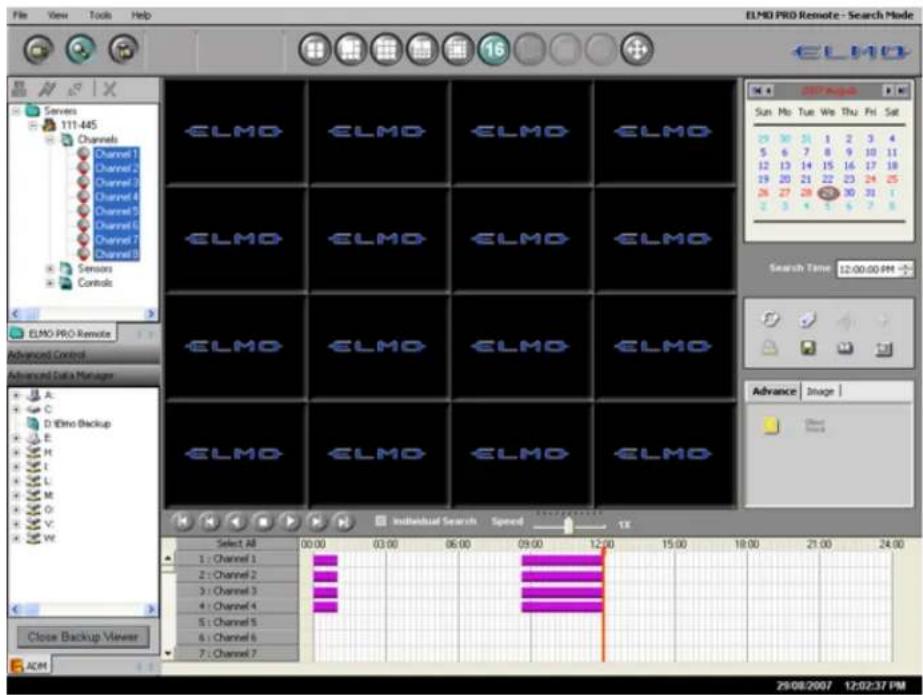
Aside from this step, searching the connected Server via ELMO-PRO Remote is very similar to Server. Please see Search on ELMO-PRO Server section for more information.
- Select the desired date of the video recording in the Calendar to load data for that spe
2.8.2. Search Offline
ELMO-PRO Remote Advanced Data Manager (ADM) allows searching data previously saved on the media. Just like in ELMO-PRO Server application, the user can launch *.i3d, *.avi, *.bmp, and
To search offline, do the following:
-
Click in Advanced Data Manager to expand this tab
-
Double click the backup file. All backup files types (*.i3d, *.avi, *.bmp, *.jpg) are identified by appropriate icons.
The ELMO format backup data will be played back inside the Search Mode screen.
The AVI backup data will be played by Windows Media player.
An image viewer will display the JPG or BMP backup files.
![Advanced Data Manager A: C: D:\Elmo Backup E: 114-335 -Encrypted ElmoProPlayer CD_DVD_204.191.16.66_Clip10[Clip 1].i3d Close Backup Viewer ADM](/content/2026/06/1226295/images/14aef5c3c30a1144b027fe108ea2602c0906b0809e889ff213fa55c07b41b506.jpg)
- In the top right of Main Screen, the current mode flow is
Click Close Backup Viewer to return to the Live Mode.
Related Topic: Search on ELMO-PRO Server
3
Appendix
Topics Covered
- ELMO-PRO Player
- Watermark Tool
Whenever an encrypted backup is burned onto a CD/DVD media, ELMO-PRO Player is added onto video, simply insert the disk into the CD-ROM drive. Provided the Autorun feature is not disab PRO Player will automatically start and the recorded video will be automatically be played.

Caution
Audio is supported by verions of ELMO-PRO player.
402
and up
click the
Open

to display
video
in the main
screen.
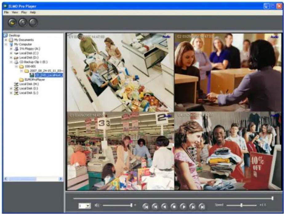
To control the video playback, use the video playback panel and the video slider in the bottom of the screen. To increase the playback speed, use the Speed slider.
Available playback speeds: -6X, -5X, -4X, -2X, 1X, 2X, 4X, 8X, 16X, 32X

To select the desired audio channel, click on the drop-down menu and select one of the available audio channels (if any). Only one audio channel at-a-time can be played back in ELMO-PRO Player.
To mute audio, click on the speaker icon.
To print an image, double-click the desired video channel and click the Print button .
To save an image as a BMP or a JPEG file, double-click the desired video channel and click the Save button

3.2. Watermark Tool
With Watermark tool it is possible to check the backup snapshot authenticity.
To use Watermark Tool, locate the watermark.exe in C:/ELMO Server or inside the ELMOProPlayer folder on the encrypted backup CD/DVD.

- Double-click on the file to launch the WaterMark checker. The following window will be dis

-
Click the Browse button and locate the JPEG or BMP snapshot.
-
Click Check WaterMark to verify the snapshot authenticity.
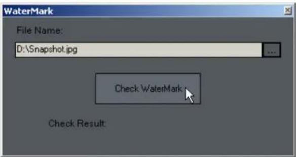
- If the snapshot is authentic and has not been tampered with, the "Match!" message will

- If the snapshot has been tampered with and is no longer authentic, the following message
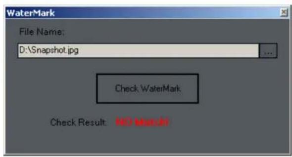
- ELMO-PRO v.1.403.16 - User Manual
- Table of Contents
- 1
- ELMO-PRO Server
- Topics Covered
- Introduction
- Welcome
- Limited Warranty
- Warning
- General
- Precautions
- Before installing this system, always ensure the:
- Unpacking
- To unpack the DVR, follow these steps:
- DVR Back View
- Key Features
- Channel oriented system
- Starting ELMO-PRO Server
- Caution
- Logging In/Out
- To log into the ELMO-PRO Server, do the following:
- ELMO-PRO Main Screen Features
- Screen Divisions
- Note
- Menu Bar
- File Menu/System Shutdown
- View Menu
- Tools Menu
- Help Menu
- Real-time Display vs Mux Display
- Mux display:
- Real-time display:
- Custom Indicators in Mux display
- Drag-and-Drop feature on Mux display
- PTZ mode
- Overview
- PTZ cameras can be controlled from:
- Using the PTZ Mode
- To access the PTZ mode, do the following:
- PTZ Control Wheel
- Managing PTZ Presets
- Programming Presets
- Using PTZ Advanced Controls Panel
- Using in-cameo PTZ function
- Saving Presets
- Renaming Presets
- Deleting Presets
- Programming Preset Tour(s)
- To create a preset tour, do the following:
- To stop touring, do the following:
- To delete a preset tour, do the following:
- Programming Pattern(s)
- To create speed dome pattern, do the following:
- To rename created pattern, do the following:
- To delete created pattern, do the following:
- AUX Control Mode
- To access the AUX Control mode, do the following:
- The following auxiliary commands may be available:
- Configuring ELMO-PRO Server
- Hardware Setup - Channel Settings
- Overview
- Tip
- Important
- Creating/Modifying Channel Settings
- Channel Settings
- To setup all connected video sources, do the following:
- Hardware Setup - Control Settings
- Overview
- Active Time
- Working Sec
- Creating/Modifying Control Settings
- Hardware Setup - Sensor Settings
- Overview
- Creating/Modifying Sensor Settings
- To configure the available sensors, do the following:
- Hardware Setup - External Monitor S
- Overview
- Creating or Modifying External Monitor Setti
- To Set up an External Monitor, do the following
- Motion Setup
- Overview
- Setting up a target zone for motion detect
- To set up a target zone for a specific channel, do the following:
- Full Screen on motion function
- To configure the full screen function, do the following:
- Setup For All Channels
- To configure all channels, do the following:
- Rotate Screen
- User Management Setup
- Overview
- Auto Logout
- Creating new user accounts
- Editing existing user accounts
- ! Important
- Click the Edit button
- Deleting existing user accounts
- Schedule Setup
- Overview
- Timeline
- Basic recording schedule
- Click SUNDAY, MONDAY, TUESDAY, WEDNESDAY, THURSDAY, FRIDAY, SAT-
- Advanced recording schedule
- Add a custom schedule
- To create a custom schedule, do the following:
- Delete a custom schedule
- Server Info Setup
- Overview
- Configuring Server Info Setupz
- System Information:
- Language
- Video Setup
- Overview
- Configuring color settings
- System Setup
- Overview
- Configure System Restart Time
- To configure the system to restart, do the following:
- Watermarking
- PTZ Settings
- To configure Windows O/S automatic logon, do the following:
- To configure the Video Loss Alarm menu, do the following:
- Panic and Sensor Backup
- Understanding DVR storage structure
- Overview
- The Storage Setup displays the following:
- Allocating New Drives For Recording / Fo ting Hard Drives
- E-Map Setup
- Overview
- Configuring E-Map
- Delete the Channels/Controls/Sensors from a Emap
- Delete the E-Map bitmap image, do the ing
- E-Map on the Main Screen
- Log Records
- Overview
- Exporting Log Records
- Configuring the Filter
- Advanced Filter
- Intelli-Guard™ Setup
- Overview
- Suggestions for using Intelli-Guard™
- Creating Intelli-Guard™ detection area(s)
- To create Intelli-Guard™ detection area, do the following:
- Configuring Intelli-Guard™ detection area(s):
- Communication Setup
- Overview
- Configuring Communication Setup
- Text Overlay Setup
- Overview
- Setting up Text Overlay
- Intelli-Zone™ Setup
- Overview
- To configure selected channel for Intelli-Zone, do the following:
- Creating Intelli-Zone™ detection area(s):
- To create Intelli-Zone ™ detection area(s), do the following:
- Configuring Intelli-Zone™ detection area(s):
- IP Camera
- Overview
- Annexxus104 module supports the following resolutions:
- Add IP Camera
- Find IP Camera
- Edit IP Camera User Account(s)
- Edit IP Camera Settings
- Delete IP camera
- VideoLogix™
- Overview
- Configuring VideoLogix™
- To configure the common channel settings, do the following:
- Configuring Object/Alarm type
- Configuring Area alarm
- To configure Area alarm, do the following:
- Configuring CrossWire alarm
- To configure CrossWire alarm, do the following:
- Configuring Idle alarm
- To configure Idle alarm, do the following:
- Configuring Missing alarm
- To configure Missing alarm, do the following:
- Configuring Stop alarm
- To configure Stop alarm, do the following:
- Configuring Direction alarm
- To configure Direction alarm, do the following:
- Configuring Passthrough Counter alarm
- To configure Passthrough Counter alarm, do the following:
- VideoLogix on the Main Screen
- Recording/Display
- Overview
- To set up Recording/Display, do the following:
- Virtual Ruler
- Overview
- Configuring Virtual Ruler
- Drawing a Virtual Ruler
- Example,
- E-Mail Setup
- Triggered Sensor(s)
- Video Loss
- Scheduled Server Status
- Configuring Email Setup
- Search and Playback on ELMO-Server
- Video Search and Playback in Live
- Video Search and Playback in Searc Mode
- Screen Division Panel
- Time Panel
- Time
- Channel Activation Buttons
- 24-hour Timeline
- Timeline (normal)
- Timeline (zoom in)
- Channel Scroll Bar
- Timeline Marker
- Video Recording Bars and Types of Recording
- Switching to Daylight Saving Time
- Playback Control Panel
- Audio Recording in Search Mode
- Video Playback in Search Mode
- Video Playback from Advanced Data Manager
- To access the Advanced Data Manager (ADM), do the following:
- Using Bookmark
- To use the bookmark, do the following:
- Panorama function
- To use the Panorama function, do the following:
- OR
- Image Zoom In/Zoom Out
- Advanced Search Panel
- Index Search Panel
- i. Switch to Search by Sensor:
- ii. Switch to Search by Channel:
- i. Switch to Search by Motion:
- Object Search
- Image Settings Panel
- To enable the Image Settings panel, do the following:
- Backup on ELMO-PRO Server
- Quick CD Backup in Live Mode
- Quick CD Backup in Search Mode
- Backup Window
- The following backup parameters may be edited for each existing backup
- i Tip
- Completing (Quick CD) Video Backup Sessio
- In order to proceed with the CD-R/DVD-R backup, do the following:
- Interrupting Video Backup Session In Progre
- Creating New Video Backup Session
- To create a brand new backup session, do the following:
- Creating AVI Backup session:
- Creating Encrypted Backup session:
- Snapshot Backup
- To perform snapshot backup, do the following:
- Scheduled Backup
- Week
- d. Month
- 2
- ELMO-PRO Remote
- ELMO-PRO Remote Setup
- Creating a New Connection
- Editing an Existing Remote Site Connection
- Deleting a Remote Site
- Managing Sites
- Connecting to a Remote Site
- Activating Connected Servers
- Disconnecting from a Remote Site
- ELMO-PRO Server Setup (via Remote)
- Remote Info Setup
- Language
- Viewing Video Channels via Rer
- To view video channels from connected Server, do the following:
- Search on ELMO-PRO Remote
- Search on the Connected Site
- Search Offline
- To search offline, do the following:
- 3
- Appendix
- Watermark Tool
Brand : Elmo
Model : EDR-10PV
Category : Software