011487 - Speaker CyberData Systems - Free user manual and instructions
Find the device manual for free 011487 CyberData Systems in PDF.

User questions about 011487 CyberData Systems
0 question about this device. Answer the ones you know or ask your own.
Ask a new question about this device
Download the instructions for your Speaker in PDF format for free! Find your manual 011487 - CyberData Systems and take your electronic device back in hand. On this page are published all the documents necessary for the use of your device. 011487 by CyberData Systems.
USER MANUAL 011487 CyberData Systems
Multicast Wall Mount Speaker Operations Guide
Part #011487
Document Part #931691A
for Firmware Version 1.1.0
CyberData Corporation
3 Justin Court
Monterey, CA 93940
(831) 373-2601
SIP Speaker Operations Guide 931691A Part # 011487
COPYRIGHT NOTICE:
© 2019, CyberData Corporation, ALL RIGHTS RESERVED.
This manual and related materials are the copyrighted property of CyberData Corporation. No part of this manual or related materials may be reproduced or transmitted, in any form or by any means (except for internal use by licensed customers), without prior express written permission of CyberData Corporation. This manual, and the products, software, firmware, and/or hardware described in this manual are the property of CyberData Corporation, provided under the terms of an agreement between CyberData Corporation and recipient of this manual, and their use is subject to that agreement and its terms.
DISCLAIMER: Except as expressly and specifically stated in a written agreement executed by CyberData Corporation, CyberData Corporation makes no representation or warranty, express or implied, including any warranty or merchantability or fitness for any purpose, with respect to this manual or the products, software, firmware, and/or hardware described herein, and CyberData Corporation assumes no liability for damages or claims resulting from any use of this manual or such products, software, firmware, and/or hardware. CyberData Corporation reserves the right to make changes, without notice, to this manual and to any such product, software, firmware, and/or hardware.
OPEN SOURCE STATEMENT: Certain software components included in CyberData products are subject to the GNU General Public License (GPL) and Lesser GNU General Public License (LGPL) "open source" or "free software" licenses. Some of this Open Source Software may be owned by third parties. Open Source Software is not subject to the terms and conditions of the CyberData COPYRIGHT NOTICE or software licenses. Your right to copy, modify, and distribute any Open Source Software is determined by the terms of the GPL, LGPL, or third party, according to who licenses that software.
Software or firmware developed by CyberData that is unrelated to Open Source Software is copyrighted by CyberData, subject to the terms of CyberData licenses, and may not be copied, modified, reverse-engineered, or otherwise altered without explicit written permission from CyberData Corporation.
TRADEMARK NOTICE: CyberData Corporation and the CyberData Corporation logos are trademarks of CyberData Corporation. Other product names, trademarks, and service marks may be the trademarks or registered trademarks of their respective owners.
CyberData
The IP Endpoint Company
Technical Support
The fastest way to get technical support for your VoIP product is to submit a VoIP Technical Support form at the following website: http://support.cyberdata.net/
Phone: (831) 373-2601, Ext. 333
Email: support@cyberdata.net
Fax: (831) 373-4193
Company and product information is at www.cyberdata.net.
Revision Information
Revision 931691A, which corresponds to firmware version 1.1.0, was released on July 15, 2019.
Browsers Supported
The following browsers have been tested against firmware version 1.1.0:
- Internet Explorer (version: 11)
- Firefox (also called Mozilla Firefox) (version: 62.0)
• Chrome (version: 63.0.3239.132) - Safari (version: 12)
• Microsoft Edge (version: 42.17134.1.0)
Pictorial Alert Icons

General Alert
This pictoral alert indicates a potentially hazardous situation. This alert will be followed by a hazard level heading and more specific information about the hazard.

Ground
This pictoral alert indicates the Earth grounding connection point.
Hazard Levels
Danger: Indicates an imminently hazardous situation which, if not avoided, will result in death or serious injury. This is limited to the most extreme situations.
Warning: Indicates a potentially hazardous situation which, if not avoided, could result in death or serious injury.
Caution: Indicates a potentially hazardous situation which, if not avoided, could result in minor or moderate injury. It may also alert users against unsafe practices.
Notice: Indicates a statement of company policy (that is, a safety policy or protection of property).
The safety guidelines for the equipment in this manual do not purport to address all the safety issues of the equipment. It is the responsibility of the user to establish appropriate safety, ergonomic, and health practices and determine the applicability of regulatory limitations prior to use. Potential safety hazards are identified in this manual through the use of words Danger, Warning, and Caution, the specific hazard type, and pictorial alert icons.
Important Safety Instructions
- Read these instructions.
- Keep these instructions.
- Heed all warnings.
- Follow all instructions.
- Do not use this apparatus near water.
- Clean only with dry cloth.
- Do not block any ventilation openings. Install in accordance with the manufacturer's instructions.
- Do not install near any heat sources such as radiators, heat registers, stoves, or other apparatus (including amplifiers) that produce heat.
- Do not defeat the safety purpose of the polarized or grounding-type plug. A polarized plug has two blades with one wider than the other. A grounding type plug has two blades and a third grounding prong. The wide blade or the third prong are provided for your safety. If the provided plug does not fit into your outlet, consult an electrician for replacement of the obsolete outlet.
- Protect the power cord from being walked on or pinched particularly at plugs, convenience receptacles, and the point where they exit from the apparatus.
- Only use attachments/accessories specified by the manufacturer.
- Refer all servicing to qualified service personnel. Servicing is required when the apparatus has been damaged in any way, such as power-supply cord or plug is damaged, liquid has been spilled or objects have fallen into the apparatus, the apparatus has been exposed to rain or moisture, does not operate normally, or has been dropped.
- Prior to installation, consult local building and electrical code requirements.
- WARNING: The Multicast Wall Mount Speaker enclosure is not rated for any AC voltages!

GENERAL ALERT
Warning
Electrical Hazard: This product should be installed by a licensed electrician according to all local electrical and building codes.

GENERAL ALERT
Warning
Electrical Hazard: To prevent injury, this apparatus must be securely attached to the floor/wall in accordance with the installation instructions.

GENERAL ALERT
Warning
The PoE connector is intended for intra-building connections only and does not route to the outside plant.
Abbreviations and Terms
| Abbreviation or Term Definition | |
| A-law A standard companding algorithm, used in European digital communications systems to optimize, i.e., modify, the dynamic range of an analog signal for digitizing. | |
| AVP Audio Video Profile | |
| Cat 5 TIA/EIA-568-B Category 5 | |
| DHCP Dynamic Host Configuration Protocol | |
| LAN Local Area Network | |
| LED Light Emitting Diode | |
| Mbps Megabits per Second. | |
| NTP Network Time Protocol | |
| PBX Private Branch Exchange | |
| PoE Power over Ethernet (as per IEEE 802.3af standard) | |
| RTFM Reset Test Function Management | |
| SIP Session Initiated Protocol | |
| u-law A companding algorithm, primarily used in the digital telecommunication | |
| UC Unified Communications | |
| VoIP | Voice over Internet Protocol |
Chapter 1 Product Overview 1
1.1 How to Identify This Product ....1
1.2 Typical Configuration ....2
1.3 Product Features ....3
1.4 Supported Protocols ...... 4
1.5 Product Specifications ....5
1.6 Compliance 6
1.6.1 CE Testing 6
1.6.2 FCC Statement 6
Chapter 2 Installing the Multicast Wall Mount Speaker 7
2.1 Parts List 7
2.2 Device Configuration 8
2.2.1 Connect Power to the Speaker 9
2.2.2 Confirm that the Speaker is Operational and Linked to the Network .....11
2.2.3 Confirm the IP Address and Test the Audio 12
2.2.4 How to Set the Factory Default Settings 13
2.3.1 Factory Default Settings 14
2.3.2 Multicast Wall Mount Speaker Web Page Navigation 15
2.3.3 Using the Toggle Help Button 16
2.3.4 Log in to the Configuration Home Page 18
2.3.5 Configure the Device 22
2.3.6 Configure the Network Parameters 24
2.3.7 Configure the SSL Parameters .....27
2.3.8 Configure the Multicast Parameters ....32
2.3.9 Configure the Audio Configuration Parameters ....34
2.3.10 Configure the Events Parameters ....38
2.3.11 Configure the Autoprovisioning Parameters .....43
2.4.1 Downloading the Firmware 54
2.4.2 Reboot the Device ....57
2.5.1 Command Interface Post Commands 58
Appendix A Mounting the Speaker 60
A.1 Mounting 60
A.2 Dimensions 61
Appendix C Setting up a TFTP Server 62
C.1 Set up a TFTP Server 62
C.1.1 Autoprovisioning requires a TFTP server for hosting the configuration file. 62
C.1.2 In a LINUX Environment 62
C.1.3 In a Windows Environment 62
Appendix C Troubleshooting/Technical Support 63
C.1 Frequently Asked Questions (FAQ) 63
C.2 Documentation 63
C.3 Contact Information 64
C.4 Warranty and RMA Information ....64
Index
65
1 Product Overview
1.1 How to Identify This Product
To identify the Multicast Wall Mount Speaker, look for a model number label similar to the one shown in Figure 1-1. The model number on the label should be 011487.
Figure 1-1. Model Number Label

text_image
CyberData www.cyberdata.net Multicast Wall Mount Speaker 011487* / 021538* CE CAN ICES-3 (A)/NMB-3(A) 00:20:F7:03:83:CA V1.1.0 This device complies with part 15 of the FCC Rules. Operation is subject to the following two conditions: (1) this device may not cause harmful interference, and (2) this device must accept any interference received, including interference that may cause undesired operation. Model number Serial number begins with 4871.2 Typical Configuration
Figure 1-2 shows a typical configuration for the Multicast Wall Mount Speaker.
Figure 1-2. Typical Configuration
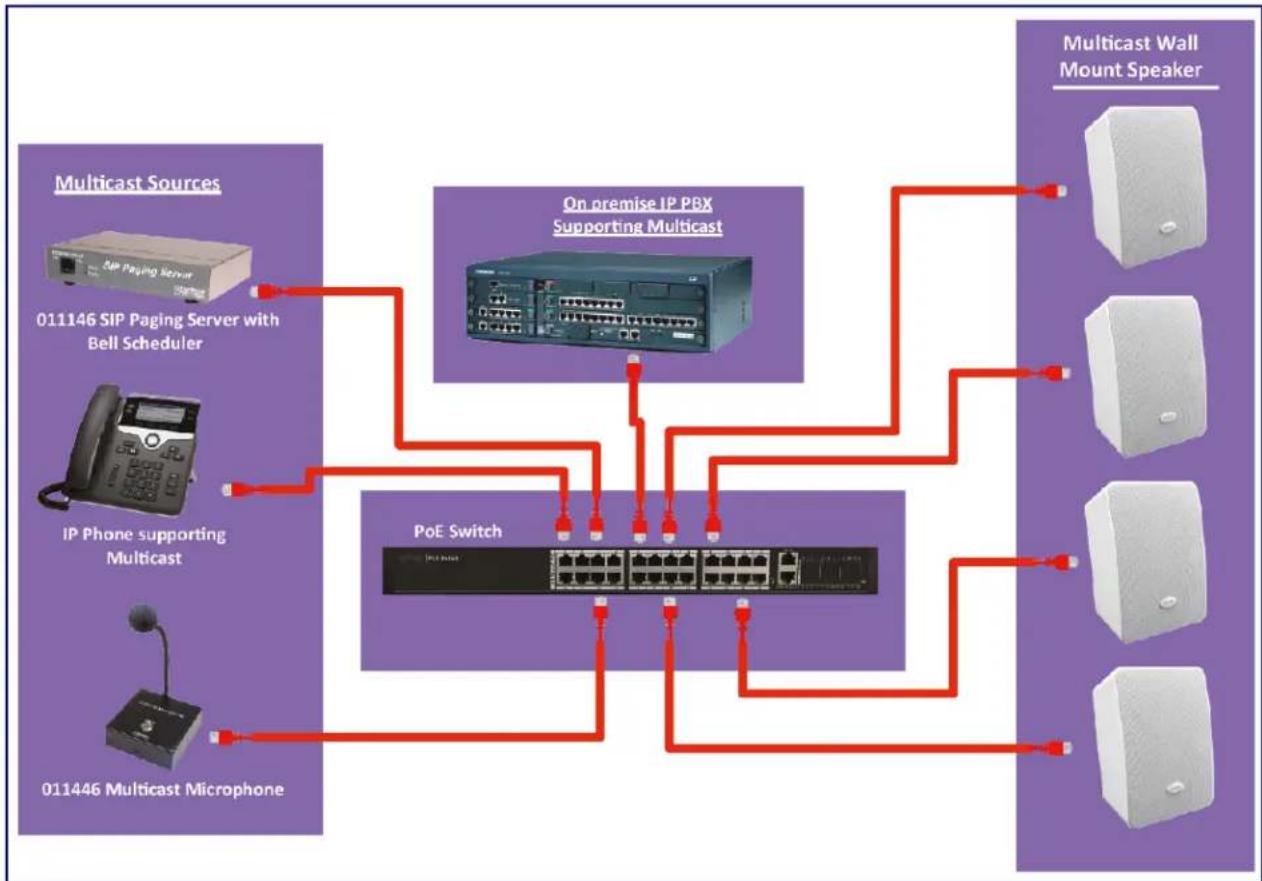
flowchart
graph TD
    A["01146 SIP Paging Server with Bell Scheduler"] --> B["On premise IP PBX Supporting Multicast"]
    C["IP Phone supporting Multicast"] --> B
    D["01146 Multicast Microphone"] --> B
    B --> E["PoE Switch"]
    E --> F["Multicast Wall Mount Speaker"]
    E --> G["Monolithic Antenna"]
    E --> H["Monolithic Antenna"]
1.3 Product Features
- Receives multicast messages
• Supports audio prioritization for 10 multicast paging groups - Can receive pages directly from Poly phones as well as other devices that can send standard multicast
• Network-adjustable speaker volume
• High efficiency speaker driver
- Small footprint
- TLS security for autoprovisioning and web-based configuration
• 802.11q VLAN tagging - Configurable event generation for device health and status monitoring
- User upgradeable firmware via web interface or autoprovisioning
1.4 Supported Protocols
The Multicast Wall Mount Speaker supports:
- Multicast
- HTTP Web-based configuration
Provides an intuitive user interface for easy system configuration and verification of speaker operations. - DHCP Client
Dynamically assigns IP addresses in addition to the option to use static addressing. - HTTP TCP Post auto-updating event notification in XML format
• TLS 1.2 - TFTP Client
Facilitates hosting for the configuration file for Autoprovisioning.
- Audio Encodings
PCMU (G.711 μ-law)
PCMA (G.711 a-law)
G.729
1.5 Product Specifications
Table 1-1. Product Specifications
| Category | Specification |
| Ethernet I/F 10/100 Mbps | |
| Protocol RTP | |
| Power Input PoE 802.3af | |
| Audio Output 802.3af - SPL 98 dB @ 1 meter | |
| Payload types G.711 a-law, G.711μ-law, and G.729 | |
| Network Security TLS/SSL 1.2 | |
| Operating Range Temperature: -40 °C to 55°C (-40°F to 131°F) | |
| Humidity: 5-95%, non-condensing | |
| Storage Temperature | -40°C to 70°C (-40°F to 158°F) |
| Storage Altitude | Up to 15,000 ft. (4573 m) |
| Dimensions 6.42 in. [163 mm] Length | |
| 5.39 in. [137 mm] Width | |
| 9.18 in. [233 mm] Height | |
| Weight | 3.8 lbs [1.72 kg] |
| Boxed Weight | 4.4 lbs [1.96 kg] |
| Compliance CE; EMC Directive - Class A EN 55032 & EN 55024, LV Safety Directive- EN 60950-1, RoHS Compliant, FCC; Part 15 Class A, Industry Canada; ICES-3 Class A, IEEE 802.3 Compliant | |
| Warranty 2 Years Limited | |
| Part number 011487 | |
1.6 Compliance
1.6.1 CE Testing
CE testing has been performed according to EN ISO/IEC 17050 for Emissions, Immunity, and Safety.
Note You can download the Declaration of Conformity document from the Downloads tab of the product's webpage.
1.6.2 FCC Statement
This equipment has been tested and found to comply with the limits for a Class B digital device, pursuant to part 15 of the FCC Rules. These limits are designed to provide reasonable protection against harmful interference when the equipment is operated in a commercial environment. This equipment generates, uses, and can radiate radio frequency energy and, if not installed and used in accordance with the instruction manual, may cause harmful interference to radio communications. Operation of this equipment in a residential area is likely to cause harmful interference in which case the user will be required to correct the interference at his own expense.
2 Installing the Multicast Wall Mount
Speaker
2.1 Parts List
Table 2-1 illustrates the parts for each speaker and includes kits for the drop ceiling and drywall mounting.
Note The installation template for the Multicast Wall Mount Speaker is located on the Installation Quick Reference Guide that is included in the packaging with each speaker.
Table 2-1. Parts
| Quantity Part Name Illustration | |
| 1 Multicast Wall Mount Speaker Assembly |  |
| 1 Installation Quick Reference Guide |  |
2.2 Device Configuration
Set up and configure each speaker before you mount it.
CyberData delivers each speaker with the following factory default values:
Table 2-2. Factory Network Default Settings—Default of Network
| Parameter Factory Default Setting | |
| IP Addressing DHCP | |
| IP Address^a | 10.10.10.10 |
| Web Access Username admin | |
| Web Access Password admin | |
| Subnet Mask^a | 255.0.0.0 |
| Default Gateway^a | 10.0.0.1 |
a. Default if there is not a DHCP server present.
2.2.1 Connect Power to the Speaker
Figure 2-1 through Figure 2-2 illustrates how to connect power to the Multicast Wall Mount Speaker.
2.2.1.1 Multicast Wall Mount Speaker to a 802.3af Compliant PoE Switch
Figure 2-1 illustrates how to connect the Multicast Wall Mount Speaker to a 802.3af compliant PoE switch via a Cat 5 Ethernet cable.
Figure 2-1. Multicast Wall Mount Speaker to a 802.3af Compliant PoE Switch

text_image
802.3af Compliant PoE Switch Cat 5 Ethernet cable Speaker2.2.1.2 Multicast Wall Mount Speaker (with PoE Injector) to a 802.3af Compliant PoE Switch
In Figure 2-2, if a PoE switch is not available, you will need a PoE Injector, part #010867A (ordered separately). A PoE Injector is a power supply solution for those who have a standard Non PoE Switch.
Figure 2-2. Multicast Wall Mount Speaker (with PoE Injector) to a Non PoE Switch
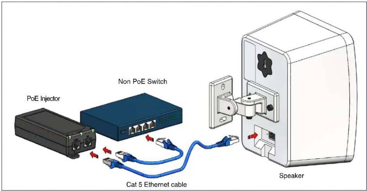
text_image
PoE Injector Non PoE Switch Cat 5 Ethernet cable Speaker2.2.2 Confirm that the Speaker is Operational and Linked to the Network
After connecting the speaker to the 802.3af compliant Ethernet hub, the LEDs on the speaker face confirm that the speaker is operational and linked to the network.
Figure 2-3. Status and Activity LEDs

text_image
Network 100 Mb (Yellow) Speaker Link/Activity (Green)2.2.2.1 Link/Activity LED
After supplying power to the speaker:
- The green Link/Activity LED comes on immediately to show that there is a good network connection, and then blinks to show network activity.
- After about 23 seconds with a static IP address (or 27 seconds if the board is set to use DHCP), the speaker should be ready.
Note If the board is set to use DHCP and there is not a DHCP server available on the network, it will try 12 times with a three second delay between tries and eventually fall back to the programmed static IP address (by default 10.10.10.10). This process will take approximately 80 seconds.
2.2.2.2 100 Mb LED
- The yellow 100 Mb LED is illuminated when the network 100 Mb link to the speaker is established.
2.2.3 Confirm the IP Address and Test the Audio
2.2.3.1 Reset Test Function Management (RTFM) Button
When the speaker is operational and linked to the network, use the Reset Test Function Management (RTFM) button (Figure 2-4) on the speaker face to announce and confirm the speaker's IP Address and test that the audio is working.
Figure 2-4. RTFM Button

text_image
RTFM buttonTo announce a speaker's current IP address, use an instrument through the hole to press and release the RTFM button within a five second window.
Note The speaker will use DHCP to obtain the new IP address (DHCP-assigned address or default to 10.10.10.10 if a DHCP server is not present).
Note Pressing and holding the RTFM button for longer than five seconds will restore the speaker to the factory default settings.
2.2.4 How to Set the Factory Default Settings
2.2.4.1 RTFM Button
When the speaker is operational and linked to the network, use the Reset Test Function Management (RTFM) button (Figure 2-5) on the speaker face to set the factory default settings.
Figure 2-5. RTFM Button

text_image
RTFM buttonTo set the factory default settings:
- Press and hold the RTFM button for more than five seconds.
- The speaker announces that it is restoring the factory default settings.
Note The speaker will use DHCP to obtain the new IP address (DHCP-assigned address or default to 10.10.10.10 if a DHCP server is not present).
2.3 Configure the Multicast Wall Mount Speaker Parameters
To configure the Multicast Wall Mount Speaker online, use a standard web browser.
Configure each Multicast Wall Mount Speaker and verify its operation before you mount it. When you are ready to mount an Multicast Wall Mount Speaker, refer to Appendix A, "Mounting the Speaker" for instructions.
2.3.1 Factory Default Settings
All Multicast Wall Mount Speakers are initially configured with the following default IP settings:
When configuring more than one Multicast Wall Mount Speaker, attach the Multicast Wall Mount Speakers to the network and configure one at a time to avoid IP address conflicts.
Table 2-3. Factory Default Settings
| Parameter Factory Default Setting | |
| IP Addressing DHCP | |
| IP Address^a | 10.10.10.10 |
| Web Access Username admin | |
| Web Access Password admin | |
| Subnet Mask^a | 255.0.0.0 |
| Default Gateway^a | 10.0.0.1 |
a. Default if there is not a DHCP server present.
2.3.2 Multicast Wall Mount Speaker Web Page Navigation
Table 2-4 shows the navigation buttons that you will see on every Multicast Wall Mount Speaker web page.
Table 2-4. Web Page Navigation
| Web Page Item Description | |
| Home | Link to theHomepage. |
| Device | Link to theDevicepage. |
| Network | Link to theNetworkpage. |
| SSL | Link to theSSLpage. |
| Multicast | Link to theMulticastpage. |
| Audiofiles | Link to theAudiofilespage. |
| Events | Link to theEventspage. |
| Autoprov | Link to theAutoprovisioningpage. |
| Firmware | Link to theFirmwarepage. |
2.3.3 Using the Toggle Help Button
The Toggle Help button allows you to see a short description of some of the settings on the webpage. To use the Toggle Help button, do the following:
- Click on the Toggle Help button that is on the UI webpage. See Figure 2-6 and Figure 2-7.
Figure 2-6. Toggle/Help Button
Toggle Help
- You will see a question mark ( ) appear next to each web page item that has been provided with a short description by the Help feature. See Figure 2-7.
Figure 2-7. Toggle Help Button and Question Marks

text_image
Stored Network Settings Addressing Mode: Static DHCP hostname: SipDevice03cab3 IP Address: 10.10.10.10 Subnet Mask: 255.0.0.0 Default gw_addr: 10.0.0.1 DNS Server 1: 10.0.0.1 DNS Server 2: 10.0.0.1 Question mark appears next to the web page items- Move the mouse pointer to hover over the question mark (☐), and a short description of the web page item will appear. See Figure 2-8.
Figure 2-8. Short Description Provided by the Help Feature
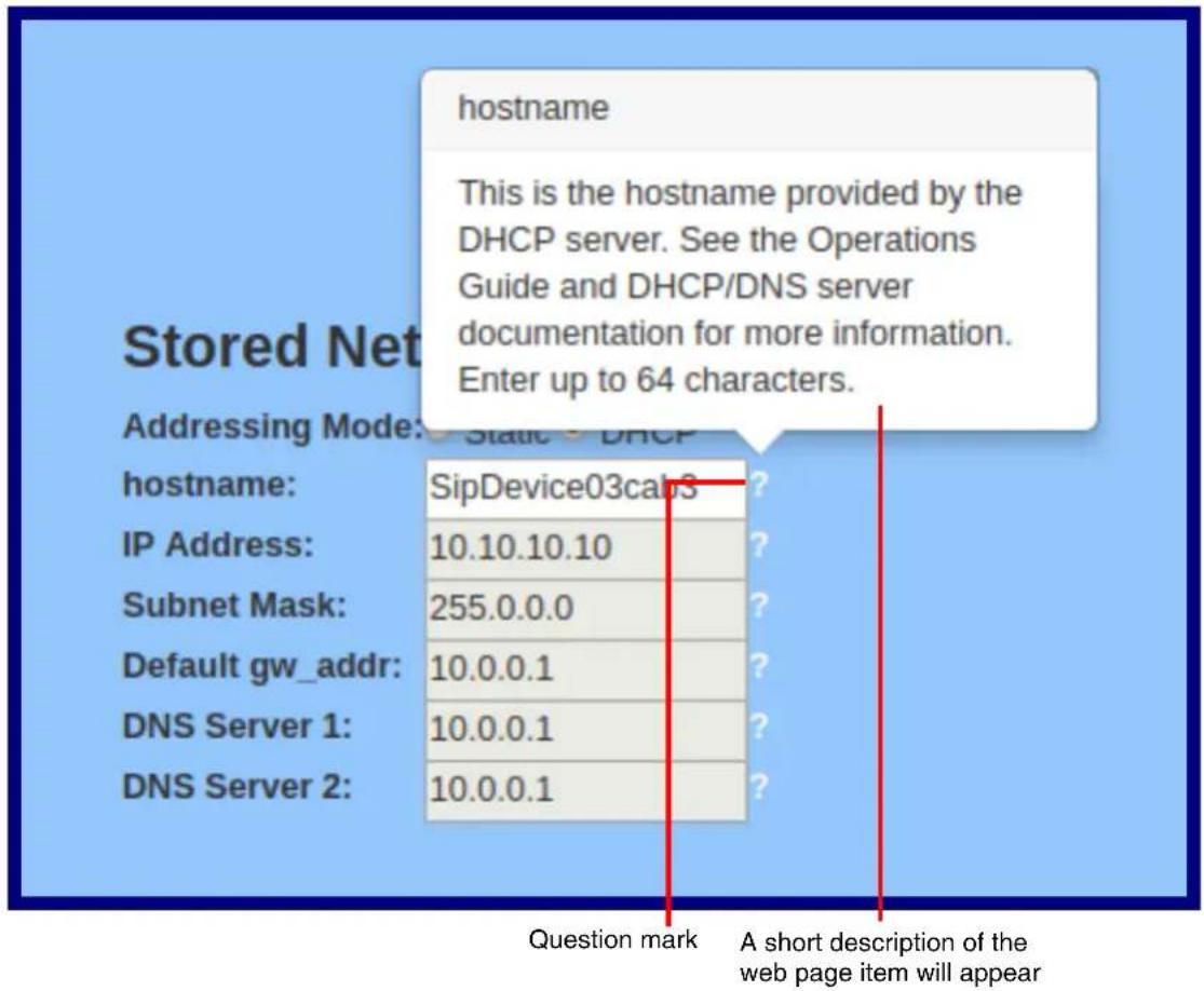
text_image
hostname This is the hostname provided by the DHCP server. See the Operations Guide and DHCP/DNS server documentation for more information. Enter up to 64 characters. Addressing Mode: Static DHCP hostname: SipDevice03cab3 IP Address: 10.10.10.10 Subnet Mask: 255.0.0.0 Default gw_addr: 10.0.0.1 DNS Server 1: 10.0.0.1 DNS Server 2: 10.0.0.1 Question mark A short description of the web page item will appear2.3.4 Log in to the Configuration Home Page
- Open your browser to the Multicast Wall Mount Speaker IP address.
Note If the network does not have access to a DHCP server, the device will default to an IP address of 10.10.10.10.
Note Make sure that the PC is on the same IP network as the Multicast Wall Mount Speaker.
Note You may also download CyberData's VoIP Discovery Utility program which allows you to easily find and configure the default web address of the CyberData VoIP products.
CyberData's VoIP Discovery Utility program is available at the following website address: https://www.cyberdata.net/pages/discovery
Note The device ships in DHCP mode. To get to the Home page, use the discovery utility to scan for the device on the network and open your browser from there.
- When prompted, use the following default Web Access Username and Web Access Password to access the Home Page (Figure 2-9):
Web Access Username: admin
Web Access Password: admin
Figure 2-9. Home Page

text_image
Home Device Network SSL Multicast Audiofiles Events Autoprov Firmware CyberData Multicast Speaker Current Status Admin Settings Import Settings Serial Number: 487000001 Username: admin Browse... No file chosen Mac Address: 00.20.f7-03.e6.94 Password: **** Firmware Version: v1.1.0 Confirm Password: **** Partition 2: v1.1.0 Partition 3: v1.1.0 Booting From: partition 2 Boot From Other Partition Save Reboot Toggle Help Export Settings Export Config IP Addressing: DHCP IP Address: 10.10.1.91 Subnet Mask: 255.0.0.0 Default Gateway: 10.0.0.1 DNS Server 1: 10.0.1.56 DNS Server 2: Multicast Volume: 4 Event Reporting: Disabled- On the Home page, review the setup details and navigation buttons described in Table 2-5.
Note The question mark icon ( ? ) in the following table shows which web page items will be defined after the Toggle Help button is pressed.
Table 2-5. Home Page Overview
| Web Page Item Description | |
| Admin Settings | |
| Username The username to access the web interface. Enter up to 25 characters. | |
| Password ? | The password to access the web interface. Enter up to 25 characters. |
| Confirm Password ? | Confirm the web interface password. |
| Current Status | |
| Serial Number Shows the device serial number. | |
| Mac Address Shows the device Mac address. | |
| Firmware Version Shows the current firmware version. | |
| Partition 2 Contains a complete copy of bootable software. | |
| Partition 3 Contains an alternate, complete copy of bootable software. | |
| Booting From Indicates the partition currently used for boot. | |
| Boot From Other Partition | Allows the user to boot from the alternate partition. |
| IP Addressing | Shows the current IP addressing setting (DHCP or static). |
| IP Address Shows the current IP address. | |
| Subnet Mask Shows the current subnet mask address. | |
| Default Gateway | Shows the current default gateway address. |
| DNS Server 1 | Shows the current DNS Server 1 address. |
| DNS Server 2 | Shows the current DNS Server 2 address. |
| Multicast Volume | Shows the current Multicast volume level. |
| Event Reporting | Shows the current status of the Event Reporting mode. |
| Import Settings | |
| Browse... | Use this button to select a configuration file to import. |
| Import Config | After selecting a configuration file, click Import to import the configuration from the selected file. Then, click Save and Reboot to store changes. |
| Export Settings | |
| Export Config | Click Export to export the current configuration to a file. |
| Save | Click the Save button to save your configuration settings. |
| Reboot | Click on the Reboot button to reboot the system. |
| Toggle Help | Click on the Toggle Help button to see a short description of some of the web page items. First click on the Toggle Help button, and you will see a question mark ( ? ) appear next to some of the web page items. Move the mouse pointer to hover over a question mark to see a short description of a specific web page item. |
2.3.5 Configure the Device
- Click the Device menu button to open the Device page. See Figure 2-10.
Figure 2-10. Device Configuration Page
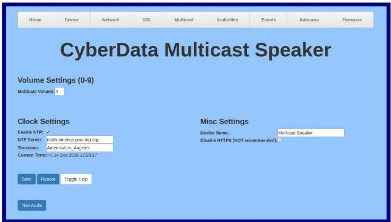
text_image
Home Device Network SSL Multicast Audiofiles Events Autoprov Firmware CyberData Multicast Speaker Volume Settings (0-9) Multicast Volume: 4 Clock Settings Enable NTP: ✓ NTP Server: north-america.pool.ntp.org Timezone: America/Los_Angeles Current Time: Fri, 14 Dec 2018 17:28:17 Save Reboot Toggle Help Misc Settings Device Name: Multicast Speaker Disable HTTPS (NOT recommended): Test Audio- On the Device page, you may enter values for the parameters indicated in Table 2-6.
Note The question mark icon ( ? ) in the following table shows which web page items will be defined after the Toggle Help button is pressed.
Table 2-6. Device Page Parameters
| Web Page Item | Description |
| Volume Settings (0-9) | |
| Multicast Volume ? | Set the speaker volume for multicast audio streams. A value of 0 will mute the speaker during multicasts.Note: You can change this setting without rebooting the device. |
| Clock Settings | |
| Enable NTP Sync device's local time with the specified NTP Server. | |
| NTP Server ? | Use this field to set the address (in IPv4 dotted decimal notation or as a canonical name) for the NTP Server. This field can accept canonical names of up to 64 characters in length. |
| Timezone Enter the tz database string of your timezone. | |
| Examples:America/Los_AngelesAmerica/New_YorkEurope/LondonAmerica/TorontoSeehttps://en.wikipedia.org/wiki/List_of_tz_database_time_zonesfor a full list of valid strings. | |
| Current Time | Displays the current time. |
| Misc Settings | |
| Device Name Type the device name. Enter up to 25 characters. | |
| Disable HTTPS (NOT recommended)? | Disables the encrypted connection to the webpage. We do not recommend disabling HTTPS for security reasons. |
| Test Audio | Click on the Test Audio button to do an audio test. When the Test Audio button is pressed, you will hear a voice message for testing the device audio quality and volume. |
| Save | Click the Save button to save your configuration settings. |
| Reboot | Click on the Reboot button to reboot the system. |
| Toggle Help | Click on the Toggle Help button to see a short description of some of the web page items. First click on the Toggle Help button, and you will see a question mark (?) appear next to some of the web page items. Move the mouse pointer to hover over a question mark to see a short description of a specific web page item. |
2.3.6 Configure the Network Parameters
- Click the Network menu button to open the Network page (Figure 2-11).
Figure 2-11. Network Configuration Page

text_image
Home Device Network SSL Multicast Audiofiles Events Autoprov Firmware CyberData Multicast Speaker Stored Network Settings Addressing Mode: Static DHCP hostname: SipDevice03e694 IP Address: 10.10.10.10 Subnet Mask: 255.0.0.0 Default Gateway: 10.0.0.1 DNS Server 1: 10.0.0.1 DNS Server 2: 10.0.0.1 VLAN Settings VLAN ID (0-4095): 0 VLAN Priority (0-7): 0 Current Network Settings IP Address: 10.10.1.91 Subnet Mask: 255.0.0.0 Default Gateway:10.0.0.1 DNS Server 1: 10.0.1.56 DNS Server 2: Save Reboot Toggle Help- On the Network page, enter values for the parameters indicated in Table 2-7.
Note The question mark icon ( ? ) in the following table shows which web page items will be defined after the Toggle Help button is pressed.
Table 2-7. Network Configuration Parameters
| Web Page Item Description | |
| Stored Network Settings | |
| Addressing Mode Select either DHCP IP Addressing or Static Addressing by marking the appropriate radio button. DHCP Addressing mode is enabled on default and the device will attempt to resolve network addressing with the local DHCP server upon boot. If DHCP Addressing fails, the device will revert to the last known IP address or the factory default address if no prior DHCP lease was established. See Section 2.3.1, "Factory Default Settings" for factory default settings. Be sure to click Save and Reboot to store changes when configuring a Static address. | |
| Hostname This is the hostname provided by the DHCP server. See the DHCP/DNS server documentation for more information. Enter up to 64 characters. | |
| IP Address Enter the Static IPv4 network address in dotted decimal notation. | |
| Subnet Mask Enter the Subnet Mask in dotted decimal notation. | |
| Default Gateway Enter the Default Gateway IPv4 address in dotted decimal notation. | |
| DNS Server 1 Enter the primary DNS Server IPv4 address in dotted decimal notation. | |
| DNS Server 2 Enter the secondary DNS Server IPv4 address in dotted decimal notation. | |
| Current Network Settings | Shows the current network settings. |
| IP Address | Shows the current Static IP address. |
| Subnet Mask | Shows the current Subnet Mask address. |
| Default Gateway | Shows the current Default Gateway address. |
| DNS Server 1 | Shows the current DNS Server 1 address. |
| DNS Server 2 | Shows the current DNS Server 2 address. |
| VLAN Settings | |
| VLAN ID (0-4095) ? | Specify the IEEE 802.1Q VLAN ID number. Enter up to 4 digits.Note: The device supports 802.1Q VLAN tagging support. The switch port connected to the device will need to be in “trunking mode” for the VLAN tags to propagate. |
| VLAN Priority (0-7) ? | Specify the IEEE 802.1p VLAN priority level. Enter 1 digit. A value of 0 may cause the VLAN ID tag to be ignored. |
| Save | Click the Save button to save your configuration settings. |
| Reboot | Click on the Reboot button to reboot the system. |
| Toggle Help | Click on the Toggle Help button to see a short description of some of the web page items. First click on the Toggle Help button, and you will see a question mark ( ) appear next to some of the web page items. Move the mouse pointer to hover over a question mark to see a short description of a specific web page item. |
Note You must click on the Save button and then the Reboot button for the changes to take effect.
2.3.7 Configure the SSL Parameters
- Click SSL menu button to open the SSL page (Figure 2-12).
Figure 2-12. SSL Configuration Page
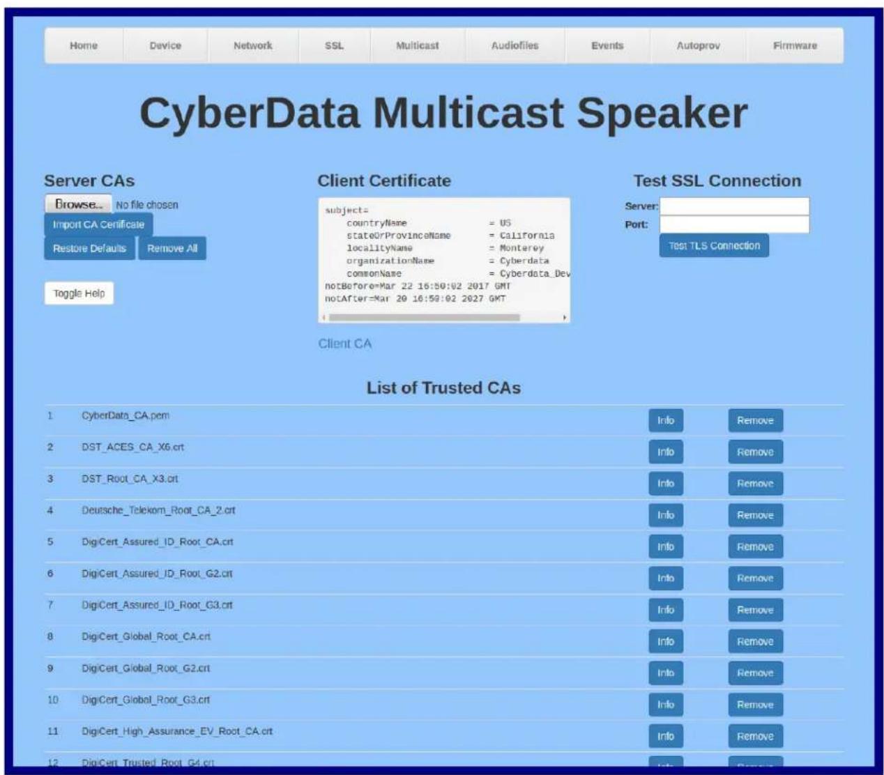
text_image
Home Device Network SSL Multicast Audiofiles Events Autoprov Firmware CyberData Multicast Speaker Server CAs Browse... No file chosen Import CA Certificate Restore Defaults Remove All Toggle Help Client Certificate subject= countryName = US stateUrProvinceName = California localityName = Monterey organizationName = Cyberdata commonName = Cyberdata_Dev notBefore=Mar 22 16:50:02 2017 GMT notAfter=Mar 20 16:50:02 2027 GMT Client CA Test SSL Connection Server: Port: Test TLS Connection List of Trusted CAs 1 CyberData_CA.pcm Info Remove 2 DSTACES_CA_X6.crt Info Remove 3 DST_Root_CA_X3.crt Info Remove 4 Deutsche_Telekom_Root_CA_2.crt Info Remove 5 DigiCert_Assured_ID_Root_CA.crt Info Remove 6 DigiCert_Assured_ID_Root_G2.crt Info Remove 7 DigiCert_Assured_ID_Root_G3.crt Info Remove 8 DigiCert_Global_Root_CA.crt Info Remove 9 DigiCert_Global_Root_G2.crt Info Remove 10 DigiCert_Global_Root_G3.crt Info Remove 11 DigiCert_High_Assurance_EV_Root_CA.crt Info Remove 12 DigiCert_Trusted_Root_G4.crt Info RemoveFigure 2-13. SSL Configuration Page
| 12 | DigiCert_Trusted_Root_G4.crt | Info | Remove |
| 13 | Equrfax_Secure_CA.crt | Info | Remove |
| 14 | Equrfax_Secure_Global_eBusiness_CA.crt | Info | Remove |
| 15 | Equrfax_Secure_eBusiness_CA_1.crt | Info | Remove |
| 16 | GeoTrust_Global_CA.crt | Info | Remove |
| 17 | GeoTrust_Global_CA_2.crt | Info | Remove |
| 18 | GeoTrust_Primary_Certification_Authority.crt | Info | Remove |
| 19 | GeoTrust_Primary_Certification_Authority_-_G2.crt | Info | Remove |
| 20 | GeoTrust_Primary_Certification_Authority_-_G3.crt | Info | Remove |
| 21 | GeoTrust_Universal_CA.crt | Info | Remove |
| 22 | GeoTrust_Universal_CA_2.crt | Info | Remove |
| 23 | VeriSign_Class_3_Public_Primary_Certification_Authority_-_G4.crt | Info | Remove |
| 24 | VeriSign_Class_3_Public_Primary_Certification_Authority_-_G5.crt | Info | Remove |
| 25 | VeriSign_Universal_Root_Certification_Authority.crt | Info | Remove |
| 26 | Verisign_Class_1_Public_Primary_Certification_Authority.crt | Info | Remove |
| 27 | Verisign_Class_1_Public_Primary_Certification_Authority_-_G3.crt | Info | Remove |
| 28 | Verisign_Class_2_Public_Primary_Certification_Authority_-_G2.crt | Info | Remove |
| 29 | Verisign_Class_2_Public_Primary_Certification_Authority_-_G3.crt | Info | Remove |
| 30 | Verisign_Class_3_Public_Primary_Certification_Authority.crt | Info | Remove |
| 31 | Verisign_Class_3_Public_Primary_Certification_Authority_-_G3.crt | Info | Remove |
| 32 | thawte_Primary_Root_CA.crt | Info | Remove |
| 33 | thawte_Primary_Root_CA_-_G2.crt | Info | Remove |
| 34 | thawte_Primary_Root_CA_-_G3.crt | Info | Remove |
- On the SSL page, enter values for the parameters indicated in Table 2-8.
Note The question mark icon ( ? ) in the following table shows which web page items will be defined after the Toggle Help button is pressed.
Table 2-8. SSL Configuration Parameters
| Web Page Item Description | |
| Server CAs | |
| Browse... | Use this button to select a configuration file to import. |
| Import CA Certificate | ClickBrowseto select a CA certificate to import. After selecting a server certificate authority (CA), clickImport CA Certificateto import it to the list of trusted CAs. CAs are used to validate the certificate presented by the server when establishing a TLS connection. |
| Restore Defaults | Restore Defaultswill restore the default list of registered CAs andRemove Allwill remove all registered CAs. |
| Remove All | Restore Defaultswill restore the default list of registered CAs andRemove Allwill remove all registered CAs. |
| Client Certificate | When doing mutual authentication this device will present a client certificate with these parameters. |
| Client CA? | Right click andSave Link As...to get the Cyberdata CA used to sign this client certificate. |
| Test SSL Connection | |
| ServerThe ssl test server address as a fully qualified domain name or in IPv4 dotted decimal notation. | |
| PortThe ssl test server port. The supported range is 0-65536. | |
| Test TLS connection | Use this button to test a TLS connection to a remote server. This will attempt to make a socket connection to the configured test server and port and report the success or failure. This can be used to debug TLS connection issues. |
| List of Trusted CAs | |
| Info | Provides details of the certificate. After clicking on this button, theCertificate Info Windowappears. SeeSection 2.3.7.1,"Certificate Info Window". |
| Remove | Removes this certificate from the list of trusted certificates. After clicking on this button, theRemove Server Certificate Windowappears. SeeSection 2.3.7.2,"Remove Server Certificate Window". |
2.3.7.1 Certificate Info Window
The Certificate Info Window provides details of the certificate. This window appears after clicking on the Info button. See Figure 2-14.
Figure 2-14. Certificate Info Window

text_image
Certificate Info subject= commonName = ACCVRAIZ1 organizationalUnitName = PKIACCV organizationName = ACCV countryName = ES notBefore=May 5 09:37:37 2011 GMT notAfter=Dec 31 09:37:37 2030 GMT2.3.7.2 Remove Server Certificate Window
The Remove Server Certificate Window will ask if the user wants to remove a certificate from the list of trusted certificates. This window appears after clicking on the Remove button. See Figure 2-15.
Figure 2-15. Remove Server Certificate Window

text_image
Remove Server Certificate Are you sure you want to remove ACCVRAIZ1.crt? Cancel Remove2.3.8 Configure the Multicast Parameters
The Multicast Configuration page allows the device to join up to ten paging zones for receiving ulaw/alaw encoded RTP audio streams.
A paging zone can consist of one or many CyberData multicast group-enabled products. There is no limit to how many speakers can be in a given paging zone. Each multicast group is defined by a multicast address and port number.
Each multicast group is assigned a priority, allowing simultaneously arriving pages to be serviced based on importance. Multicast groups are compatible with IGMP through version 3.
- Click on the Multicast menu button to open the Multicast page. See Figure 2-16.
Figure 2-16. Multicast Configuration Page

text_image
Home Device Network SSL Multicast Audiofiles Events Autoprov Firmware CyberData Multicast Speaker Multicast Settings Priority Address Port Name Beep 0 239.168.3.1 2000 Background Music 1 239.168.3.2 3000 MG1 2 239.168.3.3 4000 MG2 3 239.168.3.4 5000 MG3 4 239.168.3.5 6000 MG4 5 239.168.3.6 7000 MG5 6 239.168.3.7 8000 MG6 7 239.168.3.8 9000 MG7 8 239.168.3.9 10000 MG8 9 239.168.3.10 11000 Emergency Polycom Default Channel 1 Polycom Priority Channel 24 Polycom Emergency Channel 25 SIP calls are considered priority 4.5 Port range can be from 2000-65535 Priority 9 is the highest and 0 is the lowest A higher priority audio stream will always supersede a lower one Priority 9 streams will play at maximum volume Save Reboot- On the Multicast page, enter values for the parameters indicated in Table 2-9.
Note The question mark icon ( ? ) in the following table shows which web page items will be defined after the Toggle Help button is pressed..
Table 2-9. Multicast Page Parameters
| Web Page Item Description | |
| Priority | Indicates the priority for the multicast group. Priority 9 is the highest (emergency streams). 0 is the lowest (background music). |
| Address Enter the multicast IP Address for this multicast group (15 character limit). | |
| Port | Enter the port number for this multicast group (5 character limit [range can be from 2000 to 65535]).Note: The multicast ports have to be even values. The webpage will enforce this restriction. |
| Name Assign a descriptive name for this multicast group (25 character limit). | |
| Beep When selected, the device will play a beep before multicast audio is sent. | |
| Polycom Default Channel | When a default Polycom channel/group number is selected, the device will subscribe to the default channel for one-way group pages. Group Numbers 1-25 are supported. Or, selectDisabledto disable this channel. |
| Polycom Priority Channel | When a priority Polycom channel/group number is selected, the device will subscribe to the priority channel for one-way group pages. Group Numbers 1-25 are supported. Or, selectDisabledto disable this channel. |
| Polycom Emergency Channel When an emergency Polycom channel/group number is selected, the device will subscribe to the default channel for one-way group pages. Group Numbers 1-25 are supported. Or, selectDisabledto disable this channel. | |
| Save | Click the Save button to save your configuration settings. |
| Reboot | Click on the Reboot button to reboot the system. |
| Toggle Help | Click on the Toggle Help button to see a short description of some of the web page items. First click on the Toggle Help button, and you will see a question mark (?) appear next to some of the web page items. Move the mouse pointer to hover over a question mark to see a short description of a specific web page item. |
2.3.9 Configure the Audio Configuration Parameters
The Audiofiles page is used to add custom audio to the board. User uploaded audio will take precedence over the audio files shipped with the device.
- Click on the Audiofiles menu button to open the Audiofiles page (Figure 2-17).
Figure 2-17. Audiofiles Page

text_image
Home Device Network SSL Multicast Audiofiles Events Autoprov Firmware CyberData Multicast Speaker Available Space:1485MB 0: Currently set to: Browse... No file chosen Play Delete Save 1: Currently set to: Browse... No file chosen Play Delete Save 2: Currently set to: Browse... No file chosen Play Delete Save 3: Currently set to: Browse... No file chosen Play Delete Save 4: Currently set to: Browse... No file chosen Play Delete Save 5: Currently set to: Browse... No file chosen Play Delete Save 6: Currently set to: Browse... No file chosen Play Delete Save 7: Currently set to: Browse... No file chosen Play Delete Save 8: Currently set to: Browse... No file chosen Play Delete Save 9: Currently set to: Browse... No file chosen Play Delete Save Dot: Currently set to: Browse... No file chosen Play Delete Save Audio Test: Currently set to: Browse... No file chosen Play Delete Save Your IP Address Is:Currently set to: Browse... No file chosen Play Delete Save Rebooting: Currently set to: Browse... No file chosen Play Delete Save Restoring Default: Currently set to: Browse... No file chosen Play Delete Save- On the Audiofiles page, enter values for the parameters indicated in Table 2-10.
Note The question mark icon ( ? ) in the following table shows which web page items will be defined after the Toggle Help button is pressed.
Table 2-10. Audiofiles Page Parameters
| Web Page Item Description | |
| Available Space | Shows the space available for the user to save custom audio files if they want to change the message when the door or sensor is triggered. |
| Audio Files | |
| 0-9 | The name of the audio configuration option is the same as the spoken audio that plays on the board (24 character limit).'0' corresponds to the spoken word "zero." '1' corresponds to the spoken word "one." '2' corresponds to the spoken word "two." '3' corresponds to the spoken word "three." '4' corresponds to the spoken word "four." |
| Dot Corresponds to the spoken word "dot." (24 character limit) | |
| Audio Test Corresponds to the message "This is character limit) | the CyberData IP speaker test message..." (24 |
| Your IP Address is | Corresponds to the message "Your IP address is..." (24 character limit). |
| Rebooting | Corresponds to the spoken word "Rebooting" (24 character limit). |
| Restoring Default Corresponds to the message "Restoring default" (24 character limit). | |
| Browse... | Click on the Browse button to navigate to and select an audio file. |
| Play | The Play button will play that audio file. |
| Delete | The Delete button will delete any user uploaded audio and restore the stock audio file. |
| Save | The Save button will download a new user audio file to the board once you've selected the file by using the Browse button. The Save button will delete any pre-existing user-uploaded audio files. |
2.3.9.1 User-created Audio Files
User created audio files should be saved in the following format:
RIFF (little-endian) data, WAVE audio, Microsoft PCM, 16 bit, mono 8000 Hz
You can use the free utility Audacity to convert audio files into this format. See Figure 2-18 through Figure 2-20.
Figure 2-18. Audacity 1

text_image
audiotest File Edit View Transport Tracks Generate Effect Analyze Help I L R L R -0.30 0 0.20 0.40 0.60 0.80 1.00 1.20 1.40 1.60 1.80 X audiotest Mono, 800Hz+ 32-bit flow Mute Solo L R -1.0 1.0 0.5 0.0 -0.5 -1.0 Project Rate (Hz): Selection Start: End Length Audio Position: 8000 Snap To 00 h 00 m 00 s 00 h 00 m 00 s 00 h 00 m 00 s Click and drag to resize the track.Figure 2-19. Audacity 2

text_image
Edit Metadata Use arrow keys (or RETURN key after editing) to navigate fields. Tag Name Tag Value Artist Name Track Title Album Title Track Number Year Genre Comments Add Remove Clear Genres Template Edit... Reset... Load... Save... Set Default Cancel OKWhen you export an audio file with Audacity, save the output as:
• WAV (Microsoft) signed 16 bit PCM.
Figure 2-20. WAV (Microsoft) signed 16 bit PCM

text_image
Export File Name: audiotest.wav Save in folder: tmp Browse for other folders tmp/ Create Folder Places Search Recently Used na Desktop File System 250.1 GB Media Name Modified cscope.4371 Yesterday at 14:30 kde-na Yesterday at 14:26 kde-root Yesterday at 14:26 ksocket-na 09:20 orbit-na Yesterday at 14:32 ssh-CIPQVD3392 Yesterday at 14:26 v814422 Yesterday at 15:45 Add Remove WAV (Microsoft) signed 16 bit PCM Options... Cancel SaveWAV (Microsoft) signed 16 bit PCM
2.3.10 Configure the Events Parameters
The Events page specifies a remote server that can be used to receive HTTP POST events when actions take place on the board.
- Click on the Events menu button to open the Events page (Figure 2-21).
Figure 2-21. Event Configuration Page
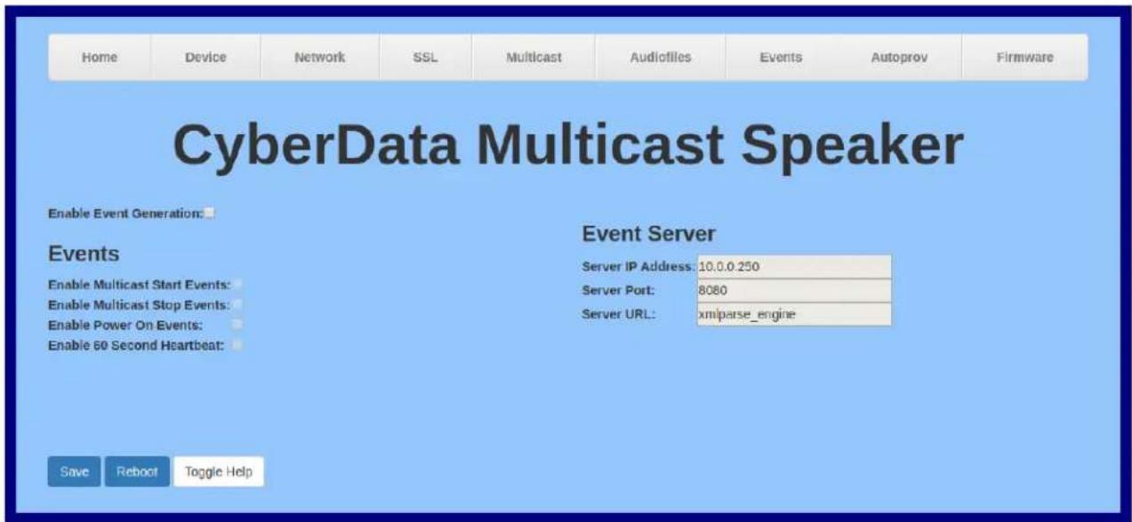
text_image
Home Device Network SSL Multicast Audiofiles Events Autoprov Firmware CyberData Multicast Speaker Enable Event Generation: Events Enable Multicast Start Events: Enable Multicast Stop Events: Enable Power On Events: Enable 60 Second Heartbeat: Event Server Server IP Address: 10.0.0.250 Server Port: 8080 Server URL: xmlparse_engine Save Reboot Toggle Help- On the Events page, enter values for the parameters indicated in Table 2-11.
Note The question mark icon ( ? ) in the following table shows which web page items will be defined after the Toggle Help button is pressed.
Table 2-11. Events Configuration Parameters
| Web Page Item Description | |
| Enable Event Generation The device will send HTTP POST events to the specified remote server and port number whenever a certain action takes place. Select an event type below to generate an HTTP POST event. | |
| Events | |
| Enable Multicast Start Events ? | When selected, the device will report when the device starts playing a multicast audio stream. |
| Enable Multicast Stop Events ? | When selected, the device will report when the device stops playing a multicast audio stream. |
| Enable Power On Events ? | When selected, the device will report when it boots. |
| Enable 60 Second Heartbeat ? | When enabled, the device will report a Heartbeat event every 60 seconds. SIP registration is not required to generate Heartbeat events. |
| Event Server | |
| Server IP Address The IPv4 address of the event server in dotted decimal notation. | |
| Server Port ? | Specify the event server port number. The supported range is 0-65536. Enter up to 5 digits. |
| Server URL ? | Generally, the destination URL is the name of the application that receives the events and the string in the HTTP POST command. It can be a script used to parse and process the HTTP POST events. Enter up to 127 characters. |
| Save | Click the Save button to save your configuration settings. |
| Reboot | Click on the Reboot button to reboot the system. |
| Toggle Help | Click on the Toggle Help button to see a short description of some of the web page items. First click on the Toggle Help button, and you will see a question mark (?) appear next to some of the web page items. Move the mouse pointer to hover over a question mark to see a short description of a specific web page item. |
2.3.10.1 Example Packets for Events
The server and port are used to point to the listening server and the 'Remote Event Server URL' is the destination URL (typically the script running on the remote server that's used to parse and process the POST events).
Note The XML is URL-encoded before transmission so the following examples are not completely accurate.
Here are example packets for every event:
POST xmlparse_engine HTTP/1.1
Host: 10.0.3.79
User-Agent: CyberData/1.1.0
Content-Length: 197
Content-Type: application/x-www-form-urlencoded

<?xml version="1.0" encoding="ISO-8859-1"?>
<cyberdata NAME='CyberData Device' MAC='0020f70015b6'>
<event>POWERON</event>
</cyberdata>

POST xmlparse_engine HTTP/1.1
Host: 10.0.3.79
User-Agent: CyberData/1.1.0
Content-Length: 199
Content-Type: application/x-www-form-urlencoded

<?xml version="1.0" encoding="ISO-8859-1"?>
<cyberdata NAME='CyberData Device' MAC='0020f70015b6'>
<event>HEARTBEAT</event>
</cyberdata>

POST xmlparse_engine HTTP/1.1
Host: 10.0.3.79
User-Agent: CyberData/1.1.0
Content-Length: 196
Content-Type: application/x-www-form-urlencoded

<?xml version="1.0" encoding="ISO-8859-1"?>
<cyberdata NAME='CyberData Device' MAC='0020f70015b6'>
<event>BUTTON</event>
</cyberdata>

POST xmlparse_engine HTTP/1.1
Host: 10.0.3.79
User-Agent: CyberData/1.1.0
Content-Length: 201
Content-Type: application/x-www-form-urlencoded

<?xml version="1.0" encoding="ISO-8859-1"?>
<cyberdata NAME='CyberData Device' MAC='0020f70015b6'>
<event>CALL_ACTIVE</event>
</cyberdata>

POST xmlparse_engine HTTP/1.1
Host: 10.0.3.79
User-Agent: CyberData/1.1.0
Content-Length: 205
Content-Type: application/x-www-form-urlencoded

<?xml version="1.0" encoding="ISO-8859-1"?>
<cyberdata NAME='CyberData Device' MAC='0020f70015b6'>
<event>CALL_TERMINATED</event>
</cyberdata>

POST xmlparse_engine HTTP/1.1
Host: 10.0.3.79
User-Agent: CyberData/1.1.0
Content-Length: 197
Content-Type: application/x-www-form-urlencoded

<?xml version="1.0" encoding="ISO-8859-1"?>
<cyberdata NAME='CyberData Device' MAC='0020f70015b6'>
<event>RINGING</event>
</cyberdata>

POST xmlparse_engine HTTP/1.1
Host: 10.0.3.79
User-Agent: CyberData/1.1.0
Content-Length: 234
Content-Type: application/x-www-form-urlencoded

<?xml version="1.0" encoding="ISO-8859-1"?>
<cyberdata NAME='CyberData Device' MAC='0020f70015b6'>
<event>MULTICAST_START</event>
<index>8</index>
</cyberdata>

POST xmlparse_engine HTTP/1.1
Host: 10.0.3.79
User-Agent: CyberData/1.1.0
Content-Length: 233
Content-Type: application/x-www-form-urlencoded

<?xml version="1.0" encoding="ISO-8859-1"?>
<cyberdata NAME='CyberData Device' MAC='0020f70015b6'>
<event>MULTICAST_STOP</event>
<index>8</index>
</cyberdata>

POST xmlparse_engine HTTP/1.1
Host: 10.0.3.79
User-Agent: CyberData/1.1.0
Content-Length: 234
Content-Type: application/x-www-form-urlencoded

<?xml version="1.0" encoding="ISO-8859-1"?>
<cyberdata NAME='CyberData Device' MAC='0020f70016b6'>
<event>RELAY_ACTIVATED</event>
</cyberdata>

POST xmlparse_engine HTTP/1.1
Host: 10.0.3.79
User-Agent: CyberData/1.1.0
Content-Length: 234
Content-Type: application/x-www-form-urlencoded
<?xml version="1.0" encoding="ISO-8859-1"?>
<cyberdata NAME='CyberData Device' MAC='0020f70015b6'>
<event>RELAY_DEACTIVATED</event>
</cyberdata>

POST xmlparse_engine HTTP/1.1
Host: 10.0.3.79
User-Agent: CyberData/1.1.0
Content-Length: 234
Content-Type: application/x-www-form-urlencoded
<?xml version="1.0" encoding="ISO-8859-1"?>
<cyberdata NAME='CyberData Device' MAC='0020f70015b6'>
<event>NIGHTRINGING</event>
</cyberdata>
2.3.11 Configure the Autoprovisioning Parameters
Autoprovisioning can be used to automatically configure your device. The autoprovisioning file is an xml file with the device configuration. Values found in this file will override values stored in on-board memory.
Note By default, the device will try to set up its configuration with autoprovisioning.
- Click the Autoprov menu button to open the Autoprovisioning page. See Figure 2-22.
Figure 2-22. Autoprovisioning Page

text_image
Home Device Network SSL Multicast Audiofiles Events Autoprov Firmware CyberData Multicast Speaker Enable Autoprovisioning: Autoprovisioning Server: Autoprovisioning Filename: Use tftp: Verify Server Certificate Username: Password: Autoprovisioning autoupdate (in minutes): 0 Autoprovision at time (HHMM): Autoprovision when idle (in minutes > 10): 0 See the manual to learn how to use autoprovisioning to configure your device. Autoprovisioning happens on boot. The device will first look for a configured server address and filename. If these haven't been configured, it will look for an autoprovisioning server in your list of DHCP options and try to download '0020f703e694.xml' and if this fails, '00000cd.xml'. Save Reboot Toggle Help Download Template Autoprovisioning log 2018-12-14 17:27:17 Autoprovd: no autoprovd triggers. Exiting... 2018-12-14 17:27:19 Autoprovisioning on boot 2018-12-14 17:27:19 Autoprov found server=https://10.0.242:4444' in dhcp option 43 2018-12-14 17:27:19 Autoprov looking for https://10.0.242:4444/0020f703e694.xml 2018-12-14 17:27:19 Autoprov not verifying server certificate 2018-12-14 17:27:19 Autoprov: download failed 2018-12-14 17:27:19 Autoprov looking for 00000cd.xml at https://10.0.242:4444 2018-12-14 17:27:19 Autoprov looking for https://10.0.242:4444/00000cd.xml 2018-12-14 17:27:19 Autoprov not verifying server certificate 2018-12-14 17:27:19 Autoprov: download failed- On the Autoprovisioning page, you may enter values for the parameters indicated in Table 2-12.
Note The question mark icon ( ? ) in the following table shows which web page items will be defined after the Toggle Help button is pressed.
Table 2-12. Autoprovisioning Page Parameters
| Web Page Item Description | |
| Enable Autoprovisioning ? | The device will automatically fetch a configuration file, also known as the 'autoprovisioning file', based on the configured settings below. |
| Autoprovisioning Server ? | Enter the IPv4 address of the provisioning server in dotted decimal notation. |
| Autoprovisioning Filename ? | The autoprovisioning filename is the configuration filename. The default autoprovisioning filename is in the format of.xml.Supported filename extensions are .txt, and .xml. The current filename is denoted by an asterisk at the bottom of theAutoprovisioning Page. Enter up to 256 characters.A file may have any name with an xml extension. If a file name is entered, the device will look for the specified file name, and only that file. |
| Use tftp ? | The device will use TFTP (instead of http) to download autoprovisioning files. |
| Verify Server Certificate ? | When using ssl to download autoprovisioning files, reject connections where the server address doesn't match the server certificate's common name. |
| Username ? | The username used to authenticate with an autoprovisioning server. Leave this field blank to disable authentication. |
| Password ? | The password used to authenticate with an autoprovisioning server. Leave this field blank to disable authentication. |
| Autoprovisioning Autoupdate (in minutes) ? | The reoccurring time (in minutes) the device will wait before checking for new autoprovisioning files. Enter up to 6 digits. A value of 0 will disable this option. |
| Autoprovision at time (HHMMSS) ? | The time of day the device will check for a new autoprovisioning file. The time must be 6 characters in length and in HHMMSS format. An empty value will disable this option. |
| Autoprovision when idle (in minutes >10) ? | The idle time (in minutes greater than 10) after which the device will check for a new autoprovisioning file. Enter up to 6 digits. A value of 0 will disable this option. |
| Save | Click the Save button to save your configuration settings. |
| Reboot | Click on the Reboot button to reboot the system. |
| Toggle Help | Click on the Toggle Help button to see a short description of some of the web page items. First click on the Toggle Help button, and you will see a question mark (?) appear next to some of the web page items. Move the mouse pointer to hover over a question mark to see a short description of a specific web page item. |
| Download Template | Press the Download Template button to create an autoprovisioning file for the device. See Section 2.3.11.3, "Download Template Button" |
| Autoprovisioning log | The autoprovisioning log provides information about the latest autoprovisioning attempt (i.e. dhcp options and server accessed and files parsed or not found). |
Note You must click on the Save button for the changes to take effect.
2.3.11.1 Autoprovisioning
On boot, the device will look for an autoprovisioning server configured on the Autoprovisioning Page or specified as a DHCP option. When it finds a server, it will try to download the following (in order of preference):
- The file configured on the autoprovisioning page.
- A file named according to it's mac address (for example: 0020f7350058.xml).
- The file 000000cd.xml
The file can be hosted using a standard web server (like apache, IIS, or nginx), and the device can download over SSL. The file server can be an ipv4 address in dotted decimal notation or a fully qualified domain name.
By default, the device will get its autoprovisioning server from the DHCP options. See Section 2.3.11.2, "Sample dhcpd.conf" for an example of how to configure dhcpd to offer autoprovisioning server addresses. If multiple options are set, the device will attempt to download autoprovisioning files from every server.
The DHCP option determines the protocol used to download the autoprovisioning file. The device looks for DHCP options in the following order:
- Option 43 - a FQDN or an IP address to an http server
- Option 72 - an IP address to an http server
- Option 150 - an IP address to a tftp server
- Option 66 - an IP address to a tftp server or if the entry starts with 'http', a FQDN to a http server.
You can download an autoprovisioning template file from the Autoprovisioning Page using the Download Template button (see Table 2-12). This file contains every configuration option that can be set on the board.
Autoprovisioning files can contain the whole configuration or a subset of this file. The first autoprovisioning file can also contain links to other autoprovisioning files.
The
<MiscSettings>
    <DeviceName>CyberData VoIP Device</DeviceName>
<!--    <AutoprovFile>common.xml</AutoprovFile-->
<!--    <AutoprovFile>sip_reg[macaddress].xml</AutoprovFile-->
<!--    <AutoprovFile>audio[macaddress]</AutoprovFile-->
<!--    <AutoprovFile>device[macaddress].xml</AutoprovFile-->
</MiscSettings>
After downloading the first autoprovisioning file, the device will step through up to twenty additional
When the device finds a filename with the string [macaddress], it will replace this string with the mac address.
As an example, the user has configured option 43 on their DHCP server to "http://example.com," and on their server, they have a file named 0020f7123456.xml (the same as the mac address of the device).
The file 0020f7123456.xml contains:
<?xml version="1.0" encoding="utf-8" ?>
<specific>
    <MiscSettings>
    <DeviceName>Newname</DeviceName>
    <AutoprovFile>common.xml</AutoprovFile>
    <AutoprovFile>sip_reg[macaddress].xml</AutoprovFile>
    <AutoprovFile>audio[macaddress]</AutoprovFile>
    <AutoprovFile>device.xml</AutoprovFile>
    </MiscSettings>
</specific>
- The device will first set it's name to 'Newname'.
- It will try to download http://example.com/common.xml.
- It will try to download http://example.com/sip_reg0020f7123456.xml.
- It will try to download http://example.com/audio0020f7123456.
- It will try to download http://example.com/device.xml.
The device is reconfigured every time it downloads a new file so if two files configure the same option the last one will be the one that is saved.
It is possible to autoprovision autoprovisioning values (for example, to disable autoprovisioning or to configure a time to check for new files).
Checking for New Autoprovisioning Files after Boot
The device will always check for an autoprovisioning files on boot but it can be configured to also check after a periodic delay, when idle, or at a specified time. When one of these options is set, the device will download its autoprovisioning files again, and if it finds any differences from the files it downloaded on boot, it will force a reboot and reconfigure.
The Autoprovisioning Filename
The autoprovisioning filename can contain a file, a file path, or a directory.
Table 2-13. Autoprovisioning File Name
| Autoprovisioning Filename | Autoprovisioning Server | File Downloaded |
| config.xml | 10.0.1.3 10.0.1.3/config.xml | |
| /path/to/config.xml | 10.0.1.3 10.0.1.3/path/to/config.xml | |
| subdirectory/path/ | 10.0.1.3 | 10.0.1.3/subdirectory/path/0020f7020002.xml |
TFTP options may not support subdirectories. If a directory is set in the filename field, firmware and audio files will also be downloaded from this subdirectory.
If the filename ends with a forward slash “/,” the device will treat it as a subdirectory.
For example:
The autoprovisioning server is set to "https://www.example.com"
The autoprovisioning filename is set to "cyberdata/"
On boot, the device will try to download:
https://www.example.com/cyberdata/0020f7123456.xml
...and if this fails:
https://www.example.com/cyberdata/000000cd.xml
Audio files and firmware files will also add "cyberdata" to the URL before downloading.
Autoprovisioning Firmware Updates
<FirmwareSettings>
    <FirmwareFile>505-uImage-ceilingspeaker</FirmwareFile>
    <FirmwareServer>10.0.1.3</FirmwareServer>
    <OutdoorIntercom30>firmware_file_v9.3.0</OutdoorIntercom30>
    <OutdoorIntercom31>firmware_file_v10.3.0</OutdoorIntercom31>
    <CallButton31>firmware_file_v10.3.0</CallButton31>
</FirmwareSettings>
In the
The device will use the filename to determine when to autoprovision firmware updates. The default configuration is blank, so the first time you set a value in your autoprovisioning file, it may force a firmware update even if the firmware version has not changed.
The
The device also supports product strings for downloading firmware. If the
The list of valid product strings:
<ProductString>CallButton31</ProductString>
 ProductString>EmergencyIntercom31</ProductString>
 ProductString>EmergencyIntercom31SW</ProductString>
 ProductString>IndoorIntercom31</ProductString>
 ProductString>IndoorIntercom31SW</ProductString>
 ProductString>IndoorKeypad31</ProductString>
 ProductString>IndoorKeypad31SW</ProductString>
 ProductString>OfficeRinger31</ProductString>
 ProductString>OfficeRinger31SW</ProductString>
 ProductString>OutdoorIntercom31</ProductString>
 ProductString>OutdoorIntercom31SW</ProductString>
 ProductString>OutdoorKeypad31</ProductString>
 ProductString>OutdoorKeypad31SW</ProductString>
 ProductString>Strobe31</ProductString>
 ProductString>Strobe31SW</ProductString>
Autoprovisioning Example 1
Here's a simple example using four autoprovisioning files to configure two devices:
We boot up two devices with mac addresses 00:20:f7:02:00:01 and 00:20:f7:02:00:02 (Device1 and Device2).
The devices are set to use DHCP and that server provides an autoprovisioning server address with option 43. The address is “https://autoprovtest.server.net.” The files on this server are as follows:
000000cd.xml

<MiscSettings>
<DeviceName>CyberData Autoprovisioned</DeviceName>
<AutoprovFile>sip_common.xml</AutoprovFile>
<AutoprovFile>sip_[macaddress].xml</AutoprovFile>
</MiscSettings>

sip_common.xml

<SIPSettings>
<SIPServer>10.0.0.253</SIPServer>
<RemoteSIPPort>5060</RemoteSIPPort>
</SIPSettings>

sip_0020f7020001.xml

<SIPSettings>
<SIPUserID>198</SIPUserID>
<SIPAuthPassword>ext198</SIPAuthPassword>
<DialoutExtension0>204</DialoutExtension0>
</SIPSettings>

sip_0020f7020002.xml

<SIPSettings>
<SIPUserID>500</SIPUserID>
<SIPAuthPassword>ext500</SIPAuthPassword>
<DialoutExtension0>555</DialoutExtension0>
</SIPSettings>
On boot, Device1 tries to fetch the file 0020f7023614.xml from "https://autoprovtest.server.net". This file is not available, so device1 then tries to fetch the file 000000cd.xml. This file exists, and Device1 parses the three elements.
- Device1 changes its device name to CyberData Autoprovisioned.
- Device1 finds an AutoprovFile element containing the filename sip_common.xml. The device downloads sip_common.xml from "https://autoprovtest.server.net," and imports this configuration, setting the sip server to 10.0.0.253 and the remote port to 5060.3.
- Device1 finds another AutoprovFile element containing the filename sip_[macaddress].xml. The device replaces the [macaddress] with its own mac address value creating sip_0020f7020001.xml, downloads this file from "https://autoprovtest.server.net," and imports this configuration. This sets the user ID to 198, the password to ext198, and the dialout extension to 204. Device1 is now finished with autoprovisioning.
Device2 goes through the same steps by setting its device name to CyberData Autoprovisioned, its SIP server to 10.0.0.253, and its port to 5060. When Device2 "sees" sip_[macaddress].xml, Device2 replaces it with its own mac address and downloads sip_0020f7020002.xml from "https://autoprovtest.server.net." Device2 sets the SIP User ID to 500, the password to ext500, and the dialout extension to 555.
Autoprovisioning Example 2
Here is another example of setting up your autoprovisioning files:
We boot up two devices with mac addresses 00:20:f7:02:00:01 and 00:20:f7:02:00:02 (Device1 and Device2) and boot them on a network with a DHCP server configured with an autoprovisioning server at 10.0.1.3 on option 150. Our TFTP server has three files:
0020f7020001.xml
<MiscSettings>
<AutoprovFile>common_settings.xml</AutoprovFile>
</MiscSettings>
<SIPSettings>
<SIPUserID>198</SIPUserID>
<SIPAuthPassword>ext198</SIPAuthPassword>
<DialogutExtension0>204</DialogutExtension0>
</SIPSettings>
0020f7020002.xml
<MiscSettings>
<AutoprovFile>common_settings.xml</AutoprovFile>
</MiscSettings>
<SIPSettings>
<SIPUserID>500</SIPUserID>
<SIPAuthPassword>ext500</SIPAuthPassword>
<DialogutExtension0>555</DialogutExtension0>
</SIPSettings>
common_settings.xml
<MiscSettings>
<DeviceName>CyberData Autoprovisioned</DeviceName>
</MiscSettings>
<SIPSettings> <SIPServer>10.0.0.253</SIPServer>
<RemoteSIPPort>5060</RemoteSIPPort>
</SIPSettings>
- On boot, Device1 downloads 0020f7020001.xml from 10.0.1.3 and imports these values. The SIP User ID is 198, the password is ext198, and the dialout extension is 204.
- Device1 then gets the filename common_settings.xml from the AutoprovFile element and downloads this file from the TFTP server at 10.0.1.3. and imports these settings. The device name is set to CyberData Autoprovisioned, the SIP server is set to 10.0.0.253, and the port is set to 5060.
Device2 does the same except it downloads 0020f7020002.xml on boot and imports these values instead. The Sip User ID is 500, password is ext500, and dialout extension is 555. Device2 then downloads the common_settings.xml file and imports those values. The device name is set to CyberData Autoprovisioned, the SIP server is set to 10.0.0.253, and the port is set to 5060.
XML Files
XML files can contain
There are numerous ways to change an element of the configuration(xml) file. Using sip ext as an example, the extension can be changed:
Within the device-specific xml, i.e. [macaddress].xml, via the AutoprovFile element:
From the device specific xml, a pointer to a sip_common file
From the device specific xml, a pointer to the device specific sip_[macaddress].xml
From the common file, a pointer to sip_common.xml
From the common file, a pointer to the device specific (sip_[macaddress].xml)
Autoprovisioned Audio Files
Audio files are stored in non-volatile memory and an autoprovisioned audio file will only have to be downloaded once for each device. Loading many audio files to the device from the web page could cause it to appear unresponsive. If this happens, wait until the transfer is complete and then refresh the page.
The device uses the file name to determine when to download a new audio file. This means that if you used autoprovisioning to upload a file and then changed the contents of this file at the TFTP server, the device will not recognize that the file has changed (because the file name is the same).
Since audio files are stored in non-volatile memory, if autoprovisioning is disabled after they have been loaded to the board, the audio file settings will not change. You can force a change to the audio files on the board by clicking Restore Default on the Audio page or by changing the autoprovisioning file with "default" set as the file name.
2.3.11.2 Sample dhcpd.conf
#
<h1 id="sample-configuration-file-for-isc-dhcpd-for-debian">Sample configuration file for ISC dhcpd for Debian</h1>
#
ddns-update-style none;

option domain-name "voiplab";
option domain-name-servers 10.0.0.252;
option option-150 code 150 = ip-address;
option ntp-servers north-america.pool.ntp.org;
option space VendorInfo;
option VendorInfo.text code 10 = { text };
authoritative;
log-facility local7;

subnet 10.0.0.0 netmask 255.0.0.0 {
    max-lease-time 3600;
    default-lease-time 3600;

    option routers    10.0.0.1;
    option subnet-mask    255.0.0.0;

    option domain-name    "voiplab";
    option domain-name-servers    10.0.0.252;

    option time-offset    -8;    # Pacific Standard Time

<h1 id="option-www-server-99999999-option-72">option www-server    99.99.99.99;    # OPTION 72</h1>

<h1 id="option-tftp-server-name-100152-option-66">option tftp-server-name    "10.0.1.52";    # OPTION 66</h1>
<h1 id="option-tftp-server-name-httptestcyberdatanet-option-66">option tftp-server-name    "http://test.cyberdata.net";    # OPTION 66</h1>

<h1 id="option-option-150-1000252-option-150">option option-150    10.0.0.252;    # OPTION 150</h1>

<h1 id="these-two-lines-are-needed-for-option-43">These two lines are needed for option 43</h1>
<h1 id="vendor-option-space-vendorinfo-option-43">vendor-option-space VendorInfo;    # OPTION 43</h1>
<h1 id="option-vendorinfotext-httptestcyberdatanet-option-43">option VendorInfo.text "http://test.cyberdata.net";    # OPTION 43</h1>

range 10.10.0.1 10.10.2.1; }
2.3.11.3 Download Template Button
The Download Template button allows the user to generate, download, edit, and then store an autoprovisioning template on the server that serves the autoprovisioning files for devices.
To generate an autoprovisioning template directly from the device, complete the following steps:
- On the Autoprovisioning page, click on the Download Template button.
- You will see a window prompting you to save a configuration file (.xml) to a location on your computer (Figure 2-23). The configuration file is the basis for the default configuration settings for your unit).
- Choose a location to save the configuration file and click on OK. See Figure 2-23.
Figure 2-23. Configuration File
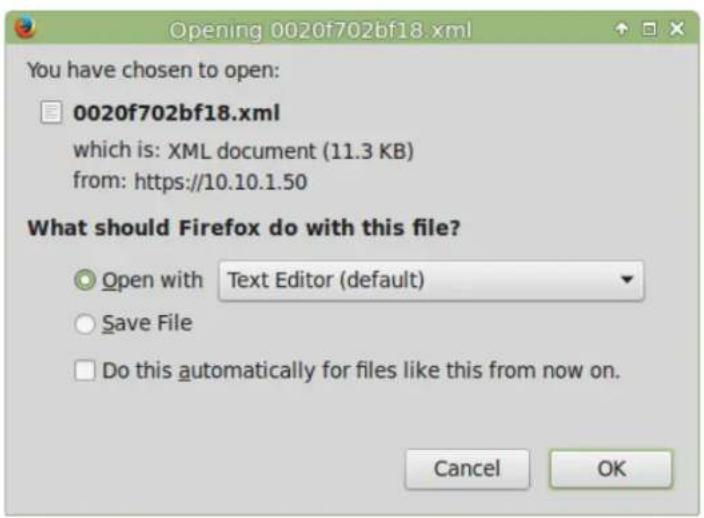
text_image
Opening 0020f702bf18.xml You have chosen to open: □ 0020f702bf18.xml which is: XML document (11.3 KB) from: https://10.10.1.50 What should Firefox do with this file? ○ Open with Text Editor (default) ○ Save File □ Do this automatically for files like this from now on. Cancel OK- At this point, you can open and edit the autoprovisioning template to change the configuration settings in the template for the unit.
- You can then upload the autoprovisioning file to a TFTP or HTTP server where the file can be loaded onto other devices.
2.4 Upgrade the Firmware and Reboot the Multicast Wall Mount Speaker
2.4.1 Downloading the Firmware
To download the firmware to your computer:
- Download the latest firmware file from the Do wnloads tab at the following webpage: http://www.cyberdata.net/products/011487/
-
Unzip the firmware version file. This file may contain the following:
-
Firmware file
- Release notes
- Log in to the Multicast Wall Mount Speaker home page as instructed in Section 2.3.4, "Log in to the Configuration Home Page".
- Click on the F irmware menu button to open the Firmware page. See Figure 2-24.

GENERAL ALERT
Caution
Equipment Hazard: CyberData strongly recommends that you first reboot the device before attempting to upgrade the firmware of the device. See Section 2.4.2, "Reboot the Device".
Figure 2-24. Firmware Page

text_image
Home Device Network SSL Multicast Audiofiles Events Autoprov Firmware CyberData Multicast Speaker Browse... No file chosen Upload Progress Upload Post Processing Status Messages Socket connected-
Click on the Browse button, and then navigate to the location of the firmware file.
-
Select the firmware file. This reveals the Upload button (Figure 2-25).
Figure 2-25. Upload Button

flowchart
graph TD
    A["Home Device Network SSL Multicast Audiofiles Events Autoprov Firmware"] --> B["Upload Progress"]
    B --> C["Upload Post Processing"]
    C --> D["Upload Progress bar"]
    D --> E["Upload Progress bar"]
    F["Browse... Upload"] --> G["Upload Messages Socket connected"]
    H["Upload button Status Messages"] --> I["Upload Progress"]
    J["Upload Post Processing bar"] --> K["Upload Progress bar"]
- Click on the Upload button. After selecting the Upload button, you will see the progress of the upload in the Upload Progress bar.
- When the upload is complete, you will see the words Upload finished under Status Messages.
- At this point, you will see the progress of the upload's post processing in the Upload Post Processing bar.
Note Do not reboot the device before the upgrading process is complete.
- When the process is complete, you will see the words SWUPDATE Successful under Status Messages.
- The device will reboot automatically.
- The Home page will display the version number of the firmware and indicate which boot partition is active.
Table 2-14 shows the web page items on the Firmware page.
Table 2-14. Firmware Page Parameters
| Web Page Item Description | |
| Browse... | Use theBrowsebutton to navigate to the location of the Intercom firmware file that you want to upload. |
| Upload | Click on theUploadbutton to automatically upload the selected firmware and reboot the system.Note: This button only appears after the user has selected a firmware file. |
| Upload progress Status bar indicates the progress in uploading the file. | |
| Upload Post Processing Status bar indicates the progress of the software installation. | |
| Status Messages Messages relevant to the firmware update process appear here. | |
2.4.2 Reboot the Device
To reboot a Multicast Wall Mount Speaker, log in to the web page as instructed in Section 2.3.4, "Log in to the Configuration Home Page".
- Click on the Reboot button on the Home page (Figure 2-26). A normal restart will occur.
Figure 2-26. Home Page

text_image
Home Device Network SSL Multicast Audiofiles Events Autoprov Firmware CyberData Multicast Speaker Current Status Serial Number: 487000001 Mac Address: 00:20:7:03:e6:94 Firmware Version: v1.1.0 Partition 2: v1.1.0 Partition 3: v1.1.0 Booting From: partition 2 Boot From Other Partition Admin Settings Username: admin Password: **** Confirm Password: **** Save Reboot Toggle Help Import Settings Browse... No file chosen Import Config Export Settings Export Config IP Addressing: DHCP IP Address: 10.10.1.91 Subnet Mask: 255.0.0.0 Default Gateway: 10.0.0.1 DNS Server 1: 10.0.1.56 DNS Server 2: Multicast Volume: 4 Event Reporting: DisabledReboot
2.5 Command Interface
Some functions on the device can be activated using simple POST commands to the web interface. The examples in Table 2-15 use the free unix utility, wget, but any program that can send http POST commands to the device should work.
2.5.1 Command Interface Post Commands
Note These commands require an authenticated session (a valid username and password to work).
Table 2-15. Command Interface Post Commands
| Device Action HTTP Post Command | a |
| Reboot wget --user admin --password admin --auth-no-challenge --quiet -O /dev/null --no-check-certificate "https://10.10.1.154/command" --post-data "request=reboot" | |
| Test Audio wget --user admin --password admin --auth-no-challenge --quiet -O /dev/null --no-check-certificate "https://10.10.1.154/command" --post-data "request=test_audio" | |
| Speak IP Address wget --user admin --password admin --auth-no-challenge --quiet -O /dev/null --no-check-certificate "https://10.10.1.154/command" --post-data "request=speak_ip_address" | |
| Play the "0" audio file | wget --user admin --password admin --auth-no-challenge --no-check-certificate "https://10.10.1.138/audiofiles/" --quiet -O /dev/null --post-data "0=Play" |
| Play the "1" audio file | wget --user admin --password admin --auth-no-challenge --no-check-certificate "https://10.10.1.138/audiofiles/" --quiet -O /dev/null --post-data "1=Play" |
| Play the "2" audio file | wget --user admin --password admin --auth-no-challenge --no-check-certificate "https://10.10.1.138/audiofiles/" --quiet -O /dev/null --post-data "2=Play" |
| Play the "3" audio file | wget --user admin --password admin --auth-no-challenge --no-check-certificate "https://10.10.1.138/audiofiles/" --quiet -O /dev/null --post-data "3=Play" |
| Play the "4" audio file | wget --user admin --password admin --auth-no-challenge --no-check-certificate "https://10.10.1.138/audiofiles/" --quiet -O /dev/null --post-data "4=Play" |
| Play the "5" audio file | wget --user admin --password admin --auth-no-challenge --no-check-certificate "https://10.10.1.138/audiofiles/" --quiet -O /dev/null --post-data "5=Play" |
| Play the "6" audio file | wget --user admin --password admin --auth-no-challenge --no-check-certificate "https://10.10.1.138/audiofiles/" --quiet -O /dev/null --post-data "6=Play" |
| Play the "7" audio file | wget --user admin --password admin --auth-no-challenge --no-check-certificate "https://10.10.1.138/audiofiles/" --quiet -O /dev/null --post-data "7=Play" |
| Play the "8" audio file | wget --user admin --password admin --auth-no-challenge --no-check-certificate "https://10.10.1.138/audiofiles/" --quiet -O /dev/null --post-data "8=Play" |
| Play the "9" audio file | wget --user admin --password admin --auth-no-challenge --no-check-certificate "https://10.10.1.138/audiofiles/" --quiet -O /dev/null --post-data "9=Play" |
| Play the "Dot" audio file | wget --user admin --password admin --auth-no-challenge --no-check-certificate "https://10.10.1.138/audiofiles/" --quiet -O /dev/null --post-data "d=Play" |
| Play the Audio Test wget --user admin --password admin --auth-no-challenge --no-check-certificate "https://10.10.1.138/audiofiles/" --quiet -O /dev/null --post-data "audiotest=Play" | |
| Play the "Page Tone" audio file | wget --user admin --password admin --auth-no-challenge --no-check-certificate "https://10.10.1.138/audiofiles/" --quiet -O /dev/null --post-data "pagetone=Play" |
| Play the "Your IP Address Is" audio file | wget --user admin --password admin --auth-no-challenge --no-check-certificate "https://10.10.1.138/audiofiles/" --quiet -O /dev/null --post-data "youripaddressis=Play" |
| Play the "Rebooting" audio file | wget --user admin --password admin --auth-no-challenge --no-check-certificate "https://10.10.1.138/audiofiles/" --quiet -O /dev/null --post-data "rebooting=Play" |
| Play the "Restoring Default" audio file | wget --user admin --password admin --auth-no-challenge --no-check-certificate "https://10.10.1.138/audiofiles/" --quiet -O /dev/null --post-data "restoringdefault=Play" |
| Swap boot partitions wget --user admin --password admin --auth-no-challenge --quiet -O /dev/null --no-check-certificate "https://10.10.1.154/command" --post-data "request=swap_boot_partition" | |
a. Type and enter all of each http POST command on one line.
Appendix A: Mounting the Speaker
A.1 Mounting
See Figure A-1 for instructions on how to mount the speaker.
Figure A-1. Mounting the Speaker
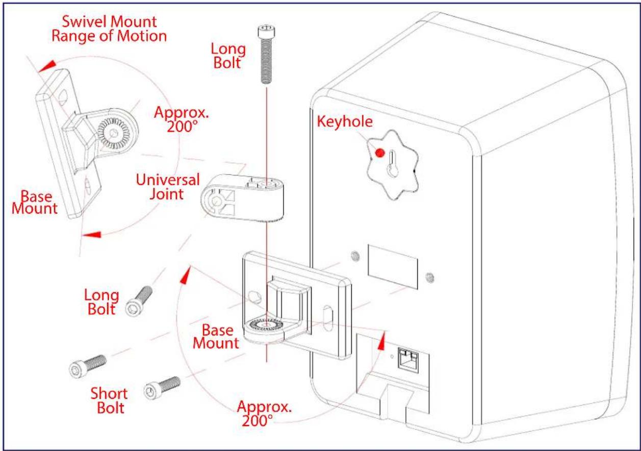
text_image
Swivel Mount Range of Motion Long Bolt Approx. 200° Base Mount Universal Joint Keyhole Long Bolt Base Mount Short Bolt Approx. 200°A.2 Dimensions
Figure A-2 shows the dimensions for the Multicast Wall Mount Speaker.
Figure A-2. Dimensions

text_image
6.419 [163.0] 5.396 [137.0] 9.178 [233.1] 1.657 [42.1] Ø0.175 [Ø4.4] Ø0.340 [Ø8.6] Keyhole Mounting Swivel Mount Mounting Bracket Dimensions are in Inches [Millimeter] Keyhole Fits Size #6 / 4mm ScrewAppendix C: Setting up a TFTP Server
C.1 Set up a TFTP Server
C.1.1 Autoprovisioning requires a TFTP server for hosting the configuration file.
C.1.2 In a LINUX Environment
To set up a TFTP server on LINUX:
- Create a directory dedicated to the TFTP server, and move the files to be uploaded to that directory.
- Run the following command where /tftpboot/ is the path to the directory you created in Step 1: the directory that contains the files to be uploaded. For example:
in.tftpd -l -s /tftpboot/your_directory_name
C.1.3 In a Windows Environment
You can find several options online for setting up a Windows TFTP server. This example explains how to use the Solarwinds freeware TFTP server, which you can download at:
https://www.cyberdata.net/pages/solarwinds
To set up a TFTP server on Windows:
- Install and start the software.
- Select File/Configure/Security tab/Transmit Only.
- Make a note of the default directory name, and then move the firmware files to be uploaded to that directory.
Appendix C: Troubleshooting/Technical Support
C.1 Frequently Asked Questions (FAQ)
To see a list of frequently asked questions for your product, click on the FAQs tab at the following webpage:
http://www.cyberdata.net/products/011487/
C.2 Documentation
The documentation for this product is released in an English language version only.
To download PDF copies of CyberData product documentation, click on the Downloads tab at the following webpage:
http://www.cyberdata.net/products/011487/
C.3 Contact Information
Contact
CyberData Corporation
3 Justin Court
Monterey, CA 93940 USA
www.CyberData.net
Phone: 800-CYBERDATA (800-292-3732)
Fax: 831-373-4193
Sales
Sales 831-373-2601, Extension 334
Technical Support
The fastest way to get technical support for your VoIP product is to submit a VoIP Technical Support form at the following website:
http://support.cyberdata.net/
The Support Form initiates a ticket which CyberData uses for tracking customer requests. Most importantly, the Support Form tells us which PBX system and software version that you are using, the make and model of the switch, and other important information. This information is essential for troubleshooting. Please also include as much detail as possible in the Comments section of the Support Form.
Phone: (831) 373-2601, Extension 333
C.4 Warranty and RMA Information
The most recent warranty and RMA information is available at the following website address:
http://support.cyberdata.net/
Index
A
address, configuration login 18
adjusting volume 13
announcing a speaker's IP address 12, 13
audio configuration 34
audio configuration page 34
audio files, user-created 36
audio output 5
audio test 12, 13
autoprovision at time (HHMMSS) 44
autoprovision when idle (in minutes > 10) 44
autoprovisioning 44, 45
download template button 44
autoprovisioning autoupdate (in minutes) 44
autoprovisioning configuration 43, 44
autoprovisioning filename 44
autoprovisioning server (IP Address) 44
C
changing
the web access password 22
command interface 58
commands 58
configurable parameters 23, 25
configuration
audio 34
default IP settings 14
device 8
door sensor 27
intrusion sensor 27
network 24
configuration home page 18
configuration page
configurable parameters 23, 25
confirming IP address 12, 13
contact information 64
contact information for CyberData 64
current network settings 25
CyberData contact information 64
D
default
gateway 8, 14
IP address 8, 14
subnet mask 8, 14
username and password 8, 14
web login username and password 18
default gateway 8, 14, 25
default IP settings 14
default login address 18
device configuration 8, 22
device configuration parameters 44
the device configuration page 43
device configuration page 22
device configuration parameters 23
device configuration password
changing for web configuration access 22
dimensions 5
discovery utility program 18
DNS server 25
download autoprovisioning template button 44
E
export settings 20
F
factory default settings
how to set 13
features 3
firmware
where to get the latest firmware 54
G
get autoprovisioning template 44
H
home page 18
http POST command 58
|
identifying your product 1
import settings 20
import/export settings 20
IP address 8, 14, 25
IP addressing
default
IP addressing setting 8, 14
L
Linux, setting up a TFTP server on 62
log in address 18
M
MGROUP
MGROUP Name 33
multicast configuration 32, 34
Multicast IP Address 33
N
navigation (web page) 15
navigation table 15
network configuration 24
network link activity, verifying 11
Nightringer 53
NTP server 23
O
overview 1
P
password
login 18
restoring the default 8, 14
polycom default channel 33
polycom emergency channel 33
polycom priority channel 33
POST command 58
power, connecting to speaker 9
product
parts list 7
product features 3
product overview 1
product features 3
product specifications 5
product specifications 5
R
reboot 56, 57
Reset Test Function Management (RTFM) button 12, 13
restoring the factory default settings 13
RTFM button 12, 13
S
sales 64
sensor setup page 27
sensor setup parameters 27
service 64
subnet mask 8, 14, 25
T
tech support 64
technical support, contact information 64
testing audio 12, 13
TFTP server 62
U
username
changing for web configuration access 22
default for web configuration access 18
restoring the default 8, 14
V
verifying
network link and activity 11
power on to speaker 11
VLAN ID 25
VLAN Priority 25
VLAN tagging support 25
VLAN tags 25
volume
multicast volume 23
volume, adjusting 13
W
warranty policy at CyberData 64
web access password 8, 14
web access username 8, 14
web configuration log in address 18
web page
navigation 15
web page navigation 15
wget, free unix utility 58
Windows, setting up a TFTP server on 62