IMX8P-IM-A - Tablet ASUS - Free user manual and instructions
Find the device manual for free IMX8P-IM-A ASUS in PDF.

User questions about IMX8P-IM-A ASUS
0 question about this device. Answer the ones you know or ask your own.
Ask a new question about this device
Download the instructions for your Tablet in PDF format for free! Find your manual IMX8P-IM-A - ASUS and take your electronic device back in hand. On this page are published all the documents necessary for the use of your device. IMX8P-IM-A by ASUS.
USER MANUAL IMX8P-IM-A ASUS
No part of this manual, including the products and software described in it, may be reproduced, transmitted, transcribed, stored in a retrieval system, or translated into any language in any form or by any means, except documentation kept by the purchaser for backup purposes, without the express written permission of ASUSTeK COMPUTER INC. ("ASUS").
ASUS PROVIDES THIS MANUAL "AS IS" WITHOUT WARRANTY OF ANY KIND, EITHER EXPRESS OR IMPLIED, INCLUDING BUT NOT LIMITED TO THE IMPLIED WARRANTIES OR CONDITIONS OF MERCHANTABILITY OR FITNESS FOR A PARTICULAR PURPOSE. IN NO EVENT SHALL ASUS, ITS DIRECTORS, OFFICERS, EMPLOYEES OR AGENTS BE LIABLE FOR ANY INDIRECT, SPECIAL, INCIDENTAL, OR CONSEQUENTIAL DAMAGES (INCLUDING DAMAGES FOR LOSS OF PROFITS, LOSS OF BUSINESS, LOSS OF USE OR DATA, INTERRUPTION OF BUSINESS AND THE LIKE), EVEN IF ASUS HAS BEEN ADVISED OF THE POSSIBILITY OF SUCH DAMAGES ARISING FROM ANY DEFECT OR ERROR IN THIS MANUAL OR PRODUCT.
Products and corporate names appearing in this manual may or may not be registered trademarks or copyrights of their respective companies, and are used only for identification or explanation and to the owners' benefit, without intent to infringe.
SPECIFICATIONS AND INFORMATION CONTAINED IN THIS MANUAL ARE FURNISHED FOR INFORMATIONAL USE ONLY, AND ARE SUBJECT TO CHANGE AT ANY TIME WITHOUT NOTICE, AND SHOULD NOT BE CONSTRUED AS A COMMITMENT BY ASUS. ASUS ASSUMES NO RESPONSIBILITY OR LIABILITY FOR ANY ERRORS OR INACCURACIES THAT MAY APPEAR IN THIS MANUAL, INCLUDING THE PRODUCTS AND SOFTWARE DESCRIBED IN IT.
Copyright © 2020 ASUSTeK COMPUTER INC. All Rights Reserved.
LIMITATION OF LIABILITY
Circumstances may arise where because of a default on ASUS' part or other liability, you are entitled to recover damages from ASUS. In each such instance, regardless of the basis on which you are entitled to claim damages from ASUS, ASUS is liable for no more than damages for bodily injury (including death) and damage to real property and tangible personal property; or any other actual and direct damages resulted from omission or failure of performing legal duties under this Warranty Statement, up to the listed contract price of each product.
ASUS will only be responsible for or indemnify you for loss, damages or claims based in contract, tort or infringement under this Warranty Statement.
This limit also applies to ASUS' suppliers and its reseller. It is the maximum for which ASUS, its suppliers, and your reseller are collectively responsible.
UNDER NO CIRCUMSTANCES IS ASUS LIABLE FOR ANY OF THE FOLLOWING: (1) THIRD-PARTY CLAIMS AGAINST YOU FOR DAMAGES; (2) LOSS OF, OR DAMAGE TO, YOUR RECORDS OR DATA; OR (3) SPECIAL, INCIDENTAL, OR INDIRECT DAMAGES OR FOR ANY ECONOMIC CONSEQUENTIAL DAMAGES (INCLUDING LOST PROFITS OR SAVINGS), EVEN IF ASUS, ITS SUPPLIERS OR YOUR RESELLER IS INFORMED OF THEIR POSSIBILITY.
SERVICE AND SUPPORT
Visit our multi-language web site at https://www.asus.com/support/
Contents
About this manual....4
Conventions used in this manual....5
Typography 5
Package contents ....6
Chapter 1: Specifications Summary
IMX8P-IM-A Specifications Summary......8
Chapter 2: Product Introduction
2.1 Before you proceed....12
2.2 Motherboard layout....13
2.3 Onboard button and switches 15
2.4 Internal connectors....17
2.5 I/O connectors....27
Chapter 3: Upgrading your Single Board Computer
3.1 Installing an Micro SD card....30
3.2 Installing the wireless card ....31
Appendix
Safety information....34
Setting up your system.... 34
Care during use.... 35
Regulatory notices....36
ASUS contact information....43
About this manual
This manual provides information about the hardware and software features of your Single Board Computer, organized through the following chapters:
Chapter 1: Specifications Summary
This chapter details the hardware and software features of your Single Board Computer.
Chapter 2: Product Introduction
This chapter describes the features of the motherboard. It includes description of the connectors, and I/O ports on the motherboard.
Chapter 3: Upgrading your Single Board Computer
This chapter provides you with information on how to upgrade your Single Board Computer.
Appendix
This section includes notices and safety statements your Single Board Computer.
Conventions used in this manual
To highlight key information in this manual, some text are presented as follows:
IMPORTANT! This message contains vital information that must be followed to complete a task.
NOTE: This message contains additional information and tips that can help complete tasks.
WARNING! This message contains important information that must be followed to keep you safe while performing certain tasks and prevent damage to your Single Board Computer's data and components.
Typography
Bold text Indicates a menu or an item to select.
Italic
This indicates sections that you can refer to in this manual.
Package contents
Your Single Board Computer package contains the following items:
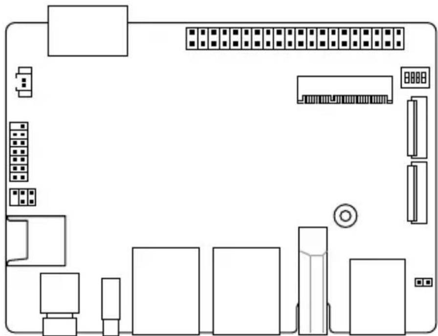
natural_image
Pure electrical circuit lines without any symbolsIMX8P-IM-A
NOTE:
- Some bundled accessories may vary with different models. For details on these accessories, refer to their respective user manuals.
- The device illustration is for reference only. Actual product specifications may vary with models.
- If the device or its components fail or malfunction during normal and proper use within the warranty period, bring the warranty card to the ASUS Service Center for replacement of the defective components.
1
Specifications Summary
IMX8P-IM-A Specifications Summary
| IMX8P-IM-A | ||
| Processor | CPU NXP® i.MX | 8 M ARM Cortex-A53 core |
| Max. Speed | 1.3 GHz | |
| L2 Cache | 1MB | |
| Chipset | Integrated | |
| Memory | Technology LPDDR4 | |
| Max. | 4GB, on board memory | |
| Storage | eMMC 1 x 16GB onboard eMMC | |
| Graphics | HDMI ^TM | 1 x HMDI ^TM supports HDMI with max. resolution 3840 x 2160 @ 60 Hz |
| MIPI DSI | 1 x MIPI DSI supports MIPI DSI (2 lane) with max. resolution 1920 x 1080 @ 60 Hz | |
| Expansion slot | M.2 | 1 x M.2 2230 E Key for BT/WiFi module (cooperate with Google EdgeTPU Module) |
| Others | 1 x Micro-SD Card slot | |
| Ethernet | Speed 10/100/1000Mbps | |
| Controller | 1 x Realtek® RTL82111 x Intel® I211-AT | |
| Connector | 2 x RJ-45 | |
| Front I/O | 1 x HDMI ^TM 2 x USB 3.2 Gen 1 Type-A ports1 x USB 3.2 Gen 1 Type-C® OTG port2 x Ethernet ports1 x Power button1 x Reset button | |
| Rear I/O | 1 x DC-in jack | |
(continued on the next page)
| IMX8P-IM-A | ||
| Internal Connector | 1 x 40-pin GPIO header:- up to 6 x GPIO pins-up to 2 x I2C bus pins-up to 1 x UART pins-up to 2 x PWM pins-up to 1 x PCM/I2S pins- 2 x 5V power pins- 2 x 3.3V power pins- 8 x ground pins1 x Micro-SD card slot1 x 14-1 pin TPM header1 x MIPI DSI supports MIPI DSI (2 lane) with max.1920 x 1080 @ 60 Hz2 x MIPI CSI support two MIPI-CSI camera inputs (4-lane each)1 x 5-1 pin I^2C header | |
| Watchdog Timer (H/W) | Yes | |
| Security Module | TPM TPM 2.0 power by Nuvoton NCPT 750 (Optional) | |
| Crypto Module | Cloud security power by Microchip ATECC608A / NXP SE050 (Optional) | |
| Manageability | WOL | |
| Power | Power Type DC power input | |
| Voltage | 12-24V DC input | |
| Operating System | Microsoft WindowsWindows® 10 IoT CoreLinuxLinux Yocto | |
| Environment | Operating Temperature: -20~60°CNon-Operating Temperature: -40~85°CRelative Humidity: 10%~95% | |
| Dimension | Form Factor 100mm x 72mm x 21mm | |
| Certification | Safety CE, FCC | |
NOTE: Specifications are subject to change without notice.
Product Introduction
2
2.1 Before you proceed
Take note of the following precautions before you install motherboard components or change any motherboard settings.
NOTE: The diagrams in this chapter are for reference only. The motherboard layout may vary with models.
IMPORTANT! Components shown in this section may require additional purchase. Refer to Package contents section for more information about the contents of your Single Board Computer package.
WARNING!
- Unplug the power cord from the wall socket before touching any component.
- Before handling components, use a grounded wrist strap or touch a safely grounded object or a metal object, such as the power supply case, to avoid damaging them due to static electricity.
- Hold components by the edges to avoid touching the ICs on them.
- Whenever you uninstall any component, place it on a grounded antistatic pad or in the bag that came with the component.
- Before you install or remove any component, ensure that the power cord is detached from the power supply. Failure to do so may cause severe damage to the motherboard, peripherals, or components.
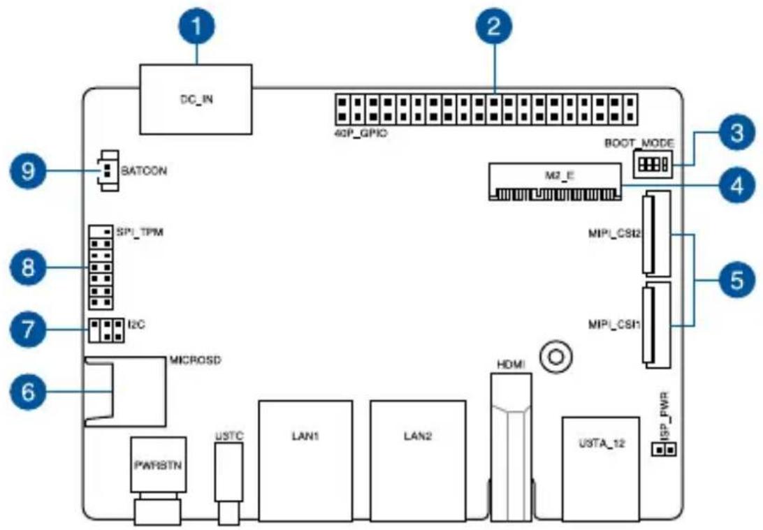
2.2 Motherboard layout
flowchart
graph TD
    A["DC_IN"] --> B["4GP_GPIO"]
    B --> C["M2_E"]
    C --> D["BOOT_MODE"]
    D --> E["M1L_CSI2"]
    D --> F["M1L_CSI1"]
    G["SATOON"] --> H["SPI_TPM"]
    H --> I["I2C"]
    J["MICROSD"] --> K["PWRBTN"]
    K --> L["USTC"]
    L --> M["LAN1"]
    M --> N["LAN2"]
    O["HDMI"] --> P["U3TA_12"]
    Q["ISP_PWR"] --> R["ISP"]
    S["9"] --> T["8"]
    T --> U["7"]
    U --> V["6"]
text_image
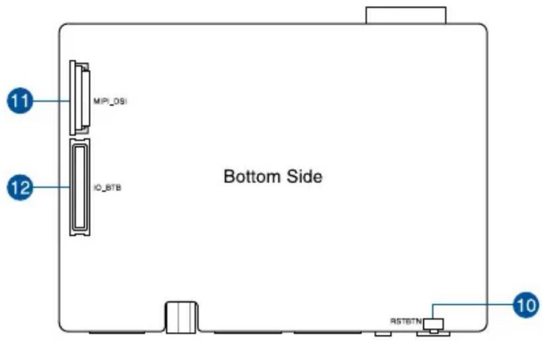
11 MIP_09I 12 IO_BTB Bottom Side RSTBTN 10| Layout contents Page | |
| 1. DC-in Power connector 19 | |
| 2. GPIO header 20 | |
| 3. Boot Mode switch 17 | |
| 4. M.2 Wi-Fi slot 20 | |
| 5. MIPI CSI connector 21 | |
| 6. Micro SD card slot 22 | |
| 7. I2C header 22 | |
| 8. SPI TPM header 23 | |
| 9. RTC Battery connector 23 | |
| 10. Reset button 18 | |
| 11. MIPI DSI connector 24 | |
| 12. IO Board-to-Board connector 25 |
2.3 Onboard button and switches
1. Boot Mode switch
The Boot Mode switch allows you to configure between different boot modes and the location to boot from. Please refer to the table below for the different boot modes.

flowchart
graph TD
    A["Start"] --> B["Boot_MODE"]
    B --> C["A: 75 C 2 L 1000 NO"]
    B --> D["B: 75 C 2 L 1000 NO"]
    B --> E["C: 95 C 2 L 1000 NO"]
    B --> F["D: 95 C 2 L 1000 NO"]
| Boot Mode | Boot type | ||
| 1 | 2 | ||
 | OFF ON Serial Downloader | ||
 | ON OFF Internal Boot (default) | ||
| Boot Mode | Boot type | ||
| 3 | 4 | ||
 | OFF ON eMMC (default) | ||
 | ON OFF SD | ||
2. Reset button
Press the Reset button to reboot the system.

text_image
Bottom Side RSTBTN2.4 Internal connectors
1. DC-in Power connector
The DC-in Power connector is for DC power input. Using a compatible power cable, connect the Pico-ITX board to a power supply.
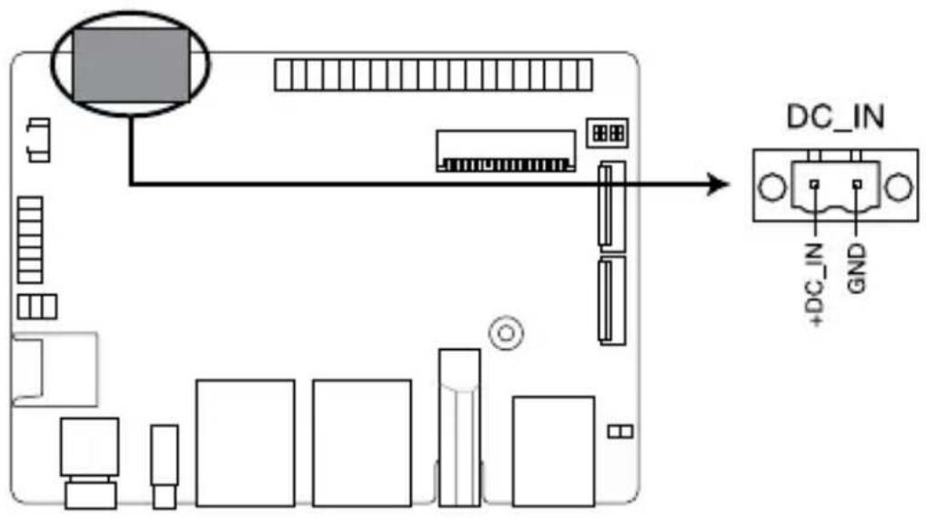
text_image
DC_IN +DC_IN GNDConnector type
POWER CON 2P R/A
Power Requirement
Rating Voltage 12 \~ 19VDC
Rating Current 5.417A \~ 3.42A
Power 65W (recommended)
2. GPIO header
This 40-pin GPIO (General-purpose Input/Output) header can be designated (in software) as an input or output pin and is used for a wide range of purposes. Of the 40 pins, 28 are GPIO pins (shared with SPI/UART/I2C pins). Please refer to the tables below for the pin definitions for Linux Yocto and Win 10 IoT Core.

text_image
40P_GPIO 1 2 3 4 5 6 7 8 9 10 11 12 13 14 15 16 17 18 19 20 21 22 23 24 25 26 27 28 29 30 31 32 33 34 35 36 37 38 39| Win 10 IoT core | |||||
| Pin definition Pin# 40P GPIO Pin# Pin definition | |||||
| 3V 1 2 | 5V | ||||
| I2C2_SDA 145 3 4 | |||||
| I2C2_SCL 144 5 6 GND | |||||
| UART1_RTS# 155 7 8 151 UART1_TXD | |||||
| GND 9 10 150 UART1_RXD | |||||
| UART1_CTS# 154 11 12 121 GPIO4_IO25 | |||||
| JTAG_TMS 13 14 GND | |||||
| JTAG_TRST 15 16 86 GPIO3_IO22 | |||||
| 3V 17 18 87 GPIO3_IO23 | |||||
| ECSPI2_MOSI 139 19 20 GND | |||||
| ECSPI2_MISO 140 21 22 JTAG_TCK | |||||
| ECSPI2_SCLK 138 23 24 141 ECSP12_SS0 | |||||
| GND 25 26 68 ECSP12_SS1 | |||||
| I2C3_SDA 147 27 28 146 I2C3_SCL | |||||
| JTAG_TDO 29 30 GND | |||||
| GPIO3_IO24 88 31 32 131 PWM3 | |||||
| PWM4 130 33 34 GND | |||||
| GPIO4_IO24 120 35 36 85 GPIO3_IO21 | |||||
| JTAG TDI 37 38 119 GPIO4_IO23 | |||||
| GND 39 40 122 GPIO4_IO26 | |||||
| Pin definition Pin# 40P GPIO Pin# Pin definition | |||||
| 3V 1 2 | 5V | ||||
| I2C2_SDA (default)ENET1_1588_EVENT1_OUTGPIO5_IO17 | 145 3 4 | ||||
| I2C2_SCL (default)ENET1_1588_EVENT1_INGPIO5_IO16 | 144 5 6 GND | ||||
| UART3_TXUART1_RTS_B (default)GPIO5_IO27 | 155 7 8 151 | UART1_TX (default)ECSPI3_MOSIGPIO5_IO23 | |||
| GND 9 10 150 | UART1_RX (default)ECSPI3_SCLKGPIO5_IO22 | ||||
| UART3_RXUART1_CTS_B (default)GPIO5_IO26 | 154 11 12 121 | SAI2_TX_BCLK (default)SAI5_TX_DATA2GPIO4_IO25 | |||
| JTAG_TMS 13 14 GND | |||||
| JTAG_TRST 15 16 86 | SAI5_RX_DATA1SAI1_TX_DATA3SAI1_TX_SYNCSAI5_TX_SYNCGPIO3_IO22 (default) | ||||
| 3V 17 18 87 | SAI5_RX_DATA2SAI1_TX_DATA4SAI1_TX_SYNCSAI5_TX_BCLKGPIO3_IO23 (default) | ||||
| ECSPI2_MOSI (default)UART4_TXGPIO5_IO11 | 139 19 20 GND | ||||
| ECSPI2_MISO (default)UART4_CTS_BGPIO5_IO12 | 140 21 22 JTAG_TCK | ||||
| ECSPI2_SCLK (default)UART4_RXGPIO5_IO10 | 138 23 24 141 | ECSPI2_SS0 (default)UART4_RTS_BGPIO5_IO13 | |||
| GND 25 26 68 | RAWNAND_CE3_BQSPI_B_SS1_B (default)GPIO3_IO04 | ||||
(continued on the next page)
| Pin definition Pin# 40P GPIO Pin# Pin definition | |||||
| I2C3_SDA (default)PWM3_OUTGPT3_CLKGPIO5_IO19 | 147 27 28 146 | I2C3_SCL(default)PWM4_OUTGPT2_CLKGPIO5_IO18 | |||
| JTAG_TDO 29 30 GND | |||||
| SAI5_RX_DATA3SAI1_TX_DATA5SAI1_TX_SYNCSAI5_TX_DATA0GPIO3_IO24 (default) | 88 31 32 131 | SPDIF1_OUTPWM3_OUT (default)GPIO5_IO03 | |||
| SAI3_MCLKPWM4_OUT (default)SAI5_MCLKGPIO5_IO02 | 130 33 34 GND | ||||
| SAI2_TX_SYNC (default)SAI5_TX_DATA1GPIO4_IO24 | 120 35 36 85 | SAI5_RX_DATA0SAI1_TX_DATA2GPIO3_IO21 (default) | |||
| JTAG TDI 37 38 119 | SAI2_RX_DATA0 (default)SAI5_TX_DATA0GPIO4_IO23 | ||||
| GND 39 40 122 | SAI2_TX_DATA0 (default)SAI5_TX_DATA3GPIO4_IO26 | ||||
Linux Yocto
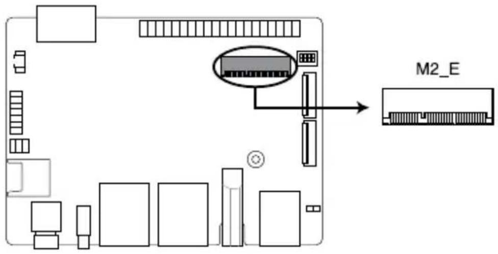
3. M.2 Wi-Fi slot
The M.2 Wi-Fi slot allows you to install an M.2 Wi-Fi module (E-key, type 2230).
text_image
M2_ENOTE: The M.2 Wi-Fi module is purchased separately.
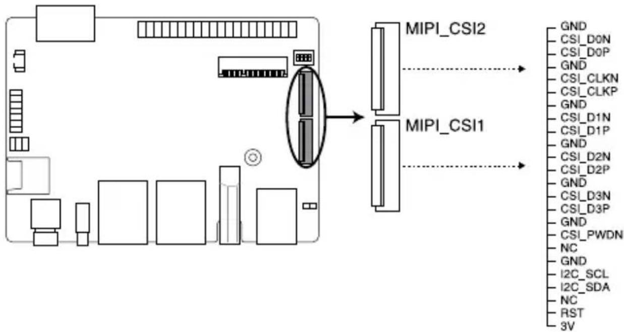
4. MIPI CSI connector
This connector connects to camera module via a four lane MIPI CSI-2 cable. This connector supports up to 80Mbps connection speed - 1.5Gbps per lane, providing 4K@30fps capability for the 4 lanes.
flowchart
graph TD
    A["Computer"] --> B["PCI"]
    B --> C["PCI"]
    C --> D["PCI"]
    D --> E["PCI"]
    E --> F["PCI"]
    F --> G["PCI"]
    G --> H["PCI"]
    H --> I["PCI"]
    I --> J["PCI"]
    J --> K["PCI"]
    K --> L["PCI"]
    L --> M["PCI"]
    M --> N["PCI"]
    N --> O["PCI"]
    O --> P["PCI"]
    P --> Q["PCI"]
    Q --> R["PCI"]
    R --> S["PCI"]
    S --> T["PCI"]
    T --> U["PCI"]
    U --> V["PCI"]
    V --> W["PCI"]
    W --> X["PCI"]
    X --> Y["PCI"]
    Y --> Z["PCI"]
    Z --> AA["PCI"]
    AA --> AB["PCI"]
    AB --> AC["PCI"]
    AC --> AD["PCI"]
    AD --> AE["PCI"]
    AE --> AF["PCI"]
    AF --> AG["PCI"]
    AG --> AH["PCI"]
    AH --> AI["PCI"]
    AI --> AJ["PCI"]
    AJ --> AK["PCI"]
    AK --> AL["PCI"]
    AL --> AM["PCI"]
    AM --> AN["PCI"]
    AN --> AO["PCI"]
    AO --> AP["PCI"]
    AP --> AQ["PCI"]
    AQ --> AR["PCI"]
IMPORTANT! Ensure the cable for MIPI CSI is connected in the correct orientation with the gold fingers facing towards the top of the motherboard.
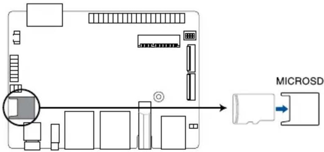
5. Micro SD Card slot
The Micro SD Card slot allows you to install a Micro SD card.
flowchart
graph TD
    A["CPU"] --> B["Memory"]
    B --> C["MicroSD"]
    C --> D["Microcontroller"]
    style A fill:#f9f,stroke:#333
    style B fill:#ccf,stroke:#333
    style C fill:#cfc,stroke:#333
    style D fill:#fcc,stroke:#333
NOTE: The Micro SD card is purchased separately.
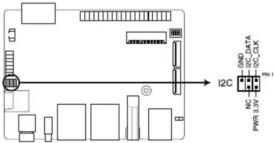
6. I²C header
The I²C (Inter-Integrated Circuit) connector allows you to connect an I²C compatible IoT security module.
text_image
I2C GND I2C_DATA I2C_CLK PIN 1 NC PWR 3.3VConnector type
Header 2x3p, K6, 2.0mm pitch
7. SPI TPM header
The SPI TPM header supports a Trusted Platform Module (TPM) system, which can securely store keys, digital certificates, passwords, and data. A TPM system also helps enhance network security, protects digital identities, and ensures platform integrity.

flowchart
graph TD
    A["Hardware"] --> B["SPI_TPM"]
    B --> C["T_SPI_HOLD#"]
    B --> D["T_SPI_MISO"]
    B --> E["S_SPI_CS0#"]
    B --> F["GND"]
    B --> G["+3VSB_SPI"]
    B --> H["NC"]
    B --> I["S_PLTRST#"]
    B --> J["S_SPI_TPM_IRQ#"]
    B --> K["VCC_SPI_TPM"]
Connector type
Header 2x7p,K14, 2.0mm pitch
8. RTC Battery connector
The RTC Battery connector allows you to connect the lithium CMOS battery.
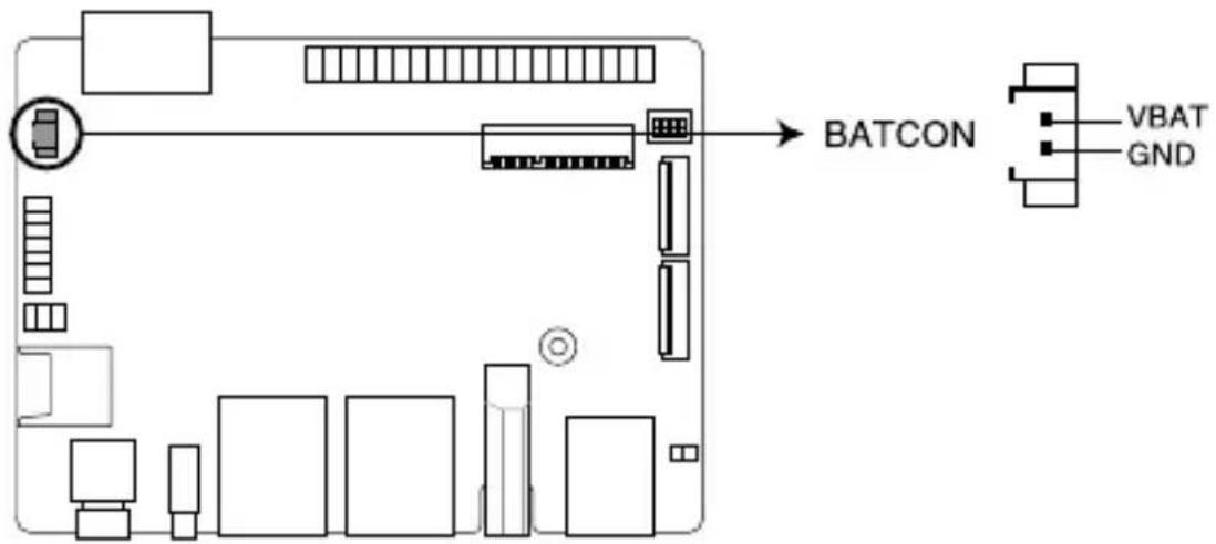
text_image
BATCON VBAT GND9. MIPI DSI connector
This connector connects to a display module via a four lane MIPI DSI cable. This connector supports up to 1920 x 1080 @ 60 Hz connection speed.

The IO Board-to-Board connector allows you to connect the Pico-ITX motherboard and secondary I/O board.

text_image
Bottom Side IO_BTB2.5 I/O connectors
Front panel

text_image
1 2 3 4 5 6 7Front panel connectors
1
Power button
The power button allows you to turn the Single Board Computer on or off. You can use the power button to put your Single Board Computer to sleep mode or press it for ten (10) seconds to force shutdown your Single Board Computer.
2
USB 3.2 Gen 1 Type-C® OTG port
This USB Type-C® OTG (Universal Serial Bus) port provides a transfer rate of up to 5 Gbit/s, and provides a maximum of 5V/1.5A output. This port supports OTG mode that can be taken to replace UART debug console.
3
LAN port
The Realtek® RTL8211 Ethernet controllers with 8-pin RJ-45 LAN port supports a standard Ethernet cable for 10/100/1000 Mbps connection to a local network.
4
LAN port
The Intel® I211-AT Gigabit Ethernet controllers with 8-pin RJ-45 LAN port supports a standard Ethernet cable for 10/100/1000 Mbps connection to a local network.
5
HDMI™ port
The integrated 19-pin HDMI (High Definition Multimedia Interface) 2.0 port with a receptacle connector can support resolutions up to 3840 x 2160 @ 60 Hz on external display devices.
6
USB 3.2 Gen 1 port
The USB 3.2 Gen 1 (Universal Serial Bus) port provides a transfer rate up to 5 Gbit/s.
Front panel connectors

Reset button
The button allows you to reset the Single Board Computer.
3
Upgrading your Single Board Computer
IMPORTANT!
- Ensure that your hands are dry before proceeding with the rest of the installation process. Before installing any of the features in this guide, use a grounded wrist strap or touch a safely grounded object or metal object to avoid damaging them due to static electricity.
- Turn off the power of your Single Board Computer, and allow it to cool for at least 10 minutes before performing any installation/uninstallation process.
NOTE: The illustrations in this section are for reference only. The slots may vary depending on model.
3.1 Installing an Micro SD card
Insert your Micro SD card into the Micro SD card slot. Ensure that the Micro SD card is pushed all the way into the Micro SD card slot.
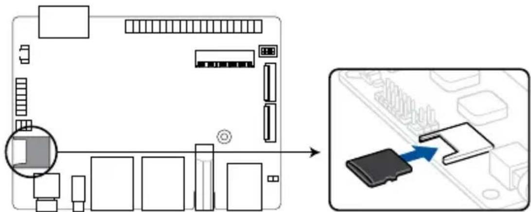
text_image
Diagram showing a computer motherboard layout with labeled components and an icon of a USB flash drive pointing to a memory card.3.2 Installing the wireless card
-
Remove the M.2 stand screw.
-
Align and insert the wireless card into its slot on the motherboard, then gently push down the wireless card on top of the screw hole and fasten it using the previously removed stand screw.
-
(optional) Connect the antennas to your wireless card.
NOTE:
- Connecting antennas to your wireless card may strengthen the wireless signal.
- A soft clicking sound indicates that the antenna has been securely attached on the wireless card.
• The antennas are purchased separately.
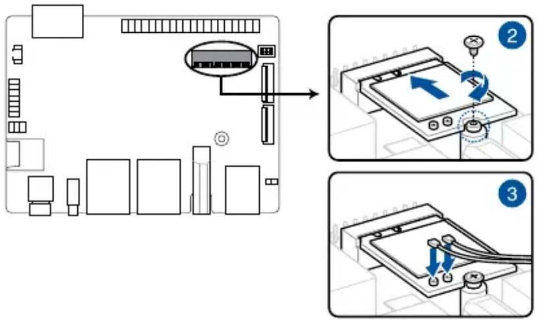
text_image
Diagram illustrating a device setup with labeled components and three-step instructions for inserting or connecting a device.Appendix
Safety information
Your Edge Computer is designed and tested to meet the latest standards of safety for information technology equipment. However, to ensure your safety, it is important that you read the following safety instructions.
Setting up your system
- Read and follow all instructions in the documentation before you operate your system.
- Do not use this product near water or a heated source.
- Set up the system on a stable surface.
- Peripherals with extended temperature tolerance (such as industrial grade mSATA, Micro SD card, etc.) will allow this product to be used in environments with ambient temperatures between -20°C and 60°C, with air flow.
- The product should be used in environments with an ambient temperature of 40^ when using the 65W adapter.
- If you use an extension cord, make sure that the total ampere rating of the devices plugged into the extension cord does not exceed its ampere rating.
- This equipment should be installed and operated with a minimum distance of 20cm between the radiator and your body.
- Restricted Access Location:
The equipment should only be installed in a Restricted Access Area where both these conditions apply:
- access can only be gained by USERS who have been instructed about the reasons for the restrictions applied to the location and about any precautions that shall be taken; and
- access is through the use of a TOOL or lock and key, or other means of security, and is controlled by the authority responsible for the location.
- This device shall not be connected to an Ethernet network with outside plant routing.
Care during use
- Do not walk on the power cord or allow anything to rest on it.
- Do not spill water or any other liquids on your system.
- When the system is turned off, a small amount of electrical current still flows. Always unplug the power cord from the power outlets before cleaning the system.
- If you encounter the following technical problems with the product, unplug the power cord and contact a qualified service technician or your retailer.
- The power cord or plug is damaged.
– Liquid has been spilled into the system. - The system does not function properly even if you follow the operating instructions.
- The system was dropped or the cabinet is damaged.
- The system performance changes.
Lithium-Ion Battery Warning
CAUTION: Danger of explosion if battery is incorrectly replaced. Replace only with the same or equivalent type recommended by the manufacturer. Dispose of used batteries according to the manufacturer's instructions.
NO DISASSEMBLY
The warranty does not apply to the products that have been disassembled by users

DO NOT throw the Edge Computer in municipal waste. This product has been designed to enable proper reuse of parts and recycling. This symbol of the crossed out wheeled bin indicates that the product (electrical, electronic equipment, and mercury-containing button cell battery) should not be placed in municipal waste. Check local technical support services for product recycling.
Regulatory notices
COATING NOTICE
IMPORTANT! To provide electrical insulation and maintain electrical safety, a coating is applied to insulate the device except on the areas where the I/O ports are located.
Federal Communications Commission Statement
This device complies with Part 15 of the FCC Rules. Operation is subject to the following two conditions:
- This device may not cause harmful interference, and
- This device must accept any interference received including interference that may cause undesired operation.
This equipment has been tested and found to comply with the limits for a Class A digital device, pursuant to part 15 of the FCC Rules. These limits are designed to provide reasonable protection against harmful interference when the equipment is operated in a commercial environment.
This equipment generates, uses, and can radiate radio frequency energy and, if not installed and used in accordance with the instruction manual, may cause harmful interference to radio communications. Operation of this equipment in a residential area is likely to cause harmful interference in which case the user will be required to correct the interference at his own expense.
IMPORTANT! Outdoor operations in the 5.15\~5.25 GHz band is prohibited. This device has no Ad-hoc capability for 5250\~5350 and 5470\~5725 MHz.
CAUTION! Any changes or modifications not expressly approved by the grantee of this device could void the user's authority to operate the equipment.
RF exposure warning
This equipment must be installed and operated in accordance with provided instructions and the antenna(s) used for this transmitter must be installed to provide a separation distance of at least 20 cm from all persons and must not be co-located or operating in conjunction with any other antenna or transmitter. End-users and installers must be provide with antenna installation instructions and transmitter operating conditions for satisfying RF exposure compliance.
End Product Labeling
This transmitter module is authorized only for use in device where the antenna may be installed such that 20cm may be maintained between the antenna and users. The final end product must be labeled in a visible area with the following:
Contains FCC ID: TX2-RTL8822CE and Contains IC:6317A-RTL8822CE
ISED Radiation Exposure Statement for Canada
This equipment complies with ISED radiation exposure limits set forth for an uncontrolled environment. To maintain compliance with ISED RF exposure compliance requirements, please avoid direct contact to the transmitting antenna during transmitting. End users must follow the specific operating instructions for satisfying RF exposure compliance.
Operation is subject to the following two conditions:
• This device may not cause interference and
- This device must accept any interference, including interference that may cause undesired operation of the device.
Compliance Statement of Innovation, Science and Economic Development Canada (ISED)
This device complies with Innovation, Science and Economic Development Canada licence exempt RSS standard(s). Operation is subject to the following two conditions: (1) this device may not cause interference, and (2) this device must accept any interference, including interference that may cause undesired operation of the device.
CAN ICES-3(A)/NMB-3(A)
Wireless Operation Channel for Different Domains
N. America 2.412-2.462 GHz Ch01 through CH11
Japan 2.412-2.484 GHz Ch01 through Ch14
Europe ETSI 2.412-2.472 GHz Ch01 through Ch13
KC: Korea Warning Statement
Class A:
사용자 안내문
Japan RF Equipment Statement
屋外での使用について
The terms HDMI, HDMI High-Definition Multimedia Interface, and the HDMI Logo are trademarks or registered trademarks of HDMI Licensing Administrator, Inc.
Declaration of compliance for product environmental regulation
ASUS follows the green design concept to design and manufacture our products, and makes sure that each stage of the product life cycle of ASUS product is in line with global environmental regulations. In addition, ASUS disclose the relevant information based on regulation requirements.
Please refer to http://csr.asus.com/Compliance.htm for information disclosure based on regulation requirements ASUS is complied with:
EU REACH and Article 33
Complying with the REACH (Registration, Evaluation, Authorization, and Restriction of Chemicals) regulatory framework, we publish the chemical substances in our products at ASUS REACH website at http://csr.asus.com/english/REACH.htm
EU RoHS
This product complies with the EU RoHS Directive. For more details, see http://csr.asus.com/english/article.aspx?id=35
Japan JIS-C-0950 Material Declarations
Information on Japan RoHS (JIS-C-0950) chemical disclosures is available on http://csr.asus.com/english/article.aspx?id=19
India RoHS
This product complies with the “India E-Waste (Management) Rules, 2016” and prohibits use of lead, mercury, hexavalent chromium, polybrominated biphenyls (PBBs) and polybrominated diphenyl ethers (PBDEs) in concentrations exceeding 0.1% by weight in homogenous materials and 0.01% by weight in homogenous materials for cadmium, except for the exemptions listed in Schedule II of the Rule.
Vietnam RoHS
ASUS products sold in Vietnam, on or after September 23, 2011, meet the requirements of the Vietnam Circular 30/2011/TT-BCT.
ASUS recycling and takeback programs come from our commitment to the highest standards for protecting our environment. We believe in providing solutions for you to be able to responsibly recycle our products, batteries, other components as well as the packaging materials. Please go to http://csr.asus.com/english/Takeback.htm for detailed recycling information in different regions.
Ecodesign Directive
European Union announced a framework for the setting of ecodesign requirements for energy-related products (2009/125/EC). Specific Implementing Measures are aimed at improving environmental performance of specific products or across multiple product types. ASUS provides product information on the CSR website. The further information could be found at https://csr.asus.com/english/article.aspx?id=1555.
| Manufacturer ASUSTeK Computer Inc. | ||
| Authorised representative in Europe | ASUSTeK Computer GmbH | |
| Address: | Harkortstrasse 21-23, 40880 Ratingen, Germany | |
ASUS contact information
ASUSTeK COMPUTER INC.
Address 1F., No. 15, Lide Rd., Beitou Dist., Taipei City 112, Taiwan
Telephone +886-2-2894-3447
Fax +886-2-2890-7798
Web site https://www.asus.com
Technical Support
Telephone +86-21-38429911
Fax +86-21-5866-8722, ext. 9101#
Online support https://www.asus.com/support/Product/ContactUs/Services/
questionform/?lang=en
ASUS COMPUTER INTERNATIONAL (America)
Address 48720 Kato Rd., Fremont, CA 94538, USA
Telephone +1-510-739-3777
Fax +1-510-608-4555
Web site http://www.asus.com/us/
Technical Support
Support fax +1-812-284-0883
Telephone +1-812-282-2787
Online support https://www.asus.com/support/Product/ContactUs/Services/
questionform/?lang=en-us
ASUS COMPUTER GmbH (Germany and Austria)
Address Harkortstrasse 21-23, 40880 Ratingen, Germany
Web site https://www.asus.com/de
Online contact https://www.asus.com/support/Product/ContactUs/Services/
questionform/?lang=de-de
Technical Support
Telephone (DE) +49-2102-5789557
Telephone (AT) +43-1360-2775461
Online support https://www.asus.com/de/support
Call center: https://www.asus.com/support/CallUs