
R2H BH059T-3 - Tablet ASUS - Free user manual and instructions
Find the device manual for free R2H BH059T-3 ASUS in PDF.


| Product Type | Tablet |
| Brand | Asus |
| Model | R2H BH059T-3 |
| Dimensions | Approximately 270 x 175 x 14 mm |
| Weight | Approximately 700 g |
| Display Size | 10.1 inches |
| Display Resolution | 1280 x 800 pixels |
| Processor | Intel Atom Z3745 |
| RAM | 2 GB |
| Storage | 32 GB eMMC |
| Operating System | Windows 8.1 |
| Battery | Lithium-ion, 31 Wh |
| Power Supply | AC adapter 19V, 2.1A |
| Main Functions | Web browsing, media playback, productivity apps, connectivity |
| Connectivity | Wi-Fi 802.11 b/g/n, Bluetooth 4.0, USB 2.0, Micro HDMI |
| Cameras | Front 2 MP, Rear 5 MP |
| Audio | Built-in speakers, microphone, headphone jack |
| Cleaning and Maintenance | Wipe gently with a soft dry cloth; avoid moisture and abrasive cleaners |
| Safety Precautions | Do not expose to extreme temperatures or liquids; use only certified chargers |
| Repairability | Spare parts available through authorized service centers; user-replaceable battery |
Frequently Asked Questions - R2H BH059T-3 ASUS
User questions about R2H BH059T-3 ASUS
0 question about this device. Answer the ones you know or ask your own.
Ask a new question about this device
Download the instructions for your Tablet in PDF format for free! Find your manual R2H BH059T-3 - ASUS and take your electronic device back in hand. On this page are published all the documents necessary for the use of your device. R2H BH059T-3 by ASUS.
USER MANUAL R2H BH059T-3 ASUS
UltraMobilePC (UMPC)
Hardware User's Manual

Table of Contents
1. Introducing the UltraMobilePC
About This User's Manual 6
Notes For This Manual 6
Safety Precautions 7
Transportation Precautions 8
Preparing your UltraMobilePC 9
2. Knowing the Parts
Front Side 12
Right Side 14
Top Side.... 16
Left Side 18
Bottom Side 19
Back Side 20
3. Getting Started
Power System 22
Using AC Power 22
Using Battery Power 23
Battery Care 23
Powering ON the UltraMobilePC 24
The Power-On Self Test (POST) 24
Checking Battery Power 25
Charging the Battery Pack 26
Power Options 26
Power Management Modes 27
Sleep and Hibernate 27
Thermal Power Control 27
Status Indicators 28
4. Using the UltraMobilePC
Display Calibration (Vista) 30
Display Calibration (XP) 31
Connections.... 32
Network Connection 32
Wireless LAN Connection (on selected models) 33
Windows Wireless Network Connection 34
ASUS Wireless LAN (on selected models) 36
Bluetooth Wireless Connection (on selected models) 38
Fingerprint Registration (on selected models) 39
GPS Software 41
Appendix
Optional Accessories 44
More Optional Accessories 47
Optional Connections 48
Glossary 52
UltraMobilePC
1. Introducing the UltraMobilePC
About This User's Manual
Notes For This Manual
Safety Precautions
Preparing your UltraMobilePC

NOTE: Photos and icons in this manual are used for artistic purposes only and do not show what is actually used in the product itself.
About This User's Manual
You are reading the UltraMobilePC User's Manual. This User's Manual provides information on the various components in the UltraMobilePC and how to use them. The following are major sections of this User's Manuals:

1. Introducing the UltraMobilePC
Introduces you to the UltraMobilePC and this User's Manual.
2. Knowing the Parts
Gives you information on the UltraMobilePC's components.
3. Getting Started
Gives you information on getting started with the UltraMobilePC.
4. Using the UltraMobilePC
Gives you information on using the UltraMobilePC's components.
5. Appendix
Introduces you to optional accessories and gives additional information.
Notes For This Manual
A few notes and warnings in bold are used throughout this guide that you should be aware of in order to complete certain tasks safely and completely. These notes have different degrees of importance as described below:

WARNING! Important information that must be followed for safe operation.

TIP: Tips and useful information for completing tasks.

IMPORTANT! Vital information that must be followed to prevent damage to data, components, or persons.

NOTE: Tips and information for special situations.
Safety Precautions
The following safety precautions will increase the life of the UltraMobilePC. Follow all precautions and instructions. Except as described in this manual, refer all servicing to qualified personnel. Do not use damaged power cords, accessories, or other peripherals. Do not use strong solvents such as thinners, benzene, or other chemicals on or near the surface.

IMPORTANT! Disconnect the AC power and remove the battery pack(s) before cleaning. Wipe the UltraMobilePC using a clean cellulose sponge or chamois cloth dampened with a solution of nonabrasive detergent and a few drops of warm water and remove any extra moisture with a dry cloth.

DO NOT place on uneven or unstable work surfaces. Seek servicing if the casing has been damaged.

DO NOT place or drop objects on top and do not shove any foreign objects into the UltraMobilePC.

DO NOT scratch the display panel. Do not place together with small items that may scratch or enter the UltraMobilePC vents.

DO NOT expose to strong magnetic or electrical fields.

DO NOT expose to dirty or dusty environments. DO NOT operate during a gas leak.

DO NOT expose to or use near liquids, rain, or moisture. DO NOT use the modem during an electrical storm.

DO NOT leave the UltraMobilePC on your lap or any part of the body in order to prevent discomfort or injury from heat exposure.

Battery safety warning: DO NOT throw the battery in fire. DO NOT short circuit the contacts. DO NOT disassemble the battery.
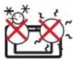
SAFE TEMP: This UltraMobilePC should only be used in environments with ambient temperatures between 5°C (41°F) and 35°C (95°F)

INPUT RATING: Refer to the rating label on the bottom of the UltraMobilePC and be sure that your power adapter complies with the rating.

DO NOT throw the UltraMobilePC in municipal waste. Check local regulations for disposal of electronic products.

DO NOT carry or cover a UltraMobilePC that is powered ON with any materials that will reduce air circulation such as a carrying bag.

Transportation Precautions
To prepare the UltraMobilePC for transport, you should turn it OFF and disconnect all external peripherals to prevent damage to the connectors. The hard disk drive's head retracts when the power is turned OFF to prevent scratching of the hard disk surface during transport. Therefore, you should not transport the UltraMobilePC while the power is still ON.

Cover Your UltraMobilePC
You can purchase an optional carrying case to protect it from dirt, water, shock, and scratches.

CAUTION: The UltraMobilePC's surface is easily dulled if not properly cared for. Be careful not to rub or scrape the UltraMobilePC surfaces who transporting your UltraMobilePC.


Charge Your Batteries
If you intend to use battery power, be sure to fully charge your battery pack and any optional battery packs before going on long trips. Remember that the power adapter charges the battery pack as long as it is plugged into the computer and an AC power source. Be aware that it takes much longer to charge the battery pack when the UltraMobilePC is in use.

Airplane Precautions
Contact your airline if you want to use the UltraMobilePC on the airplane. Most airlines will have restrictions for using electronic devices. Most airlines will allow electronic use only between and not during takeoffs and landings.

CAUTION! There are three main types of airport security devices: X-ray machines (used on items placed on conveyor belts), magnetic detectors (used on people walking through security checks), and magnetic wands (hand-held devices used on people or individual items). You can send your UltraMobilePC and diskettes through airport X-ray machines. However, it is recommended that you do not send your UltraMobilePC or diskettes through airport magnetic detectors or expose them to magnetic wands.
Preparing your UltraMobilePC
These are only quick instructions for using your UltraMobilePC. Read the later pages for detailed information on using your UltraMobilePC.
- Install the battery pack

- Connect the AC Power Adapter

- Remove the Tablet Pen 4. Turn ON the UltraMobilePC
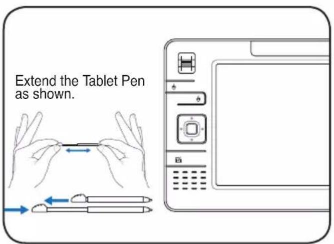

Then Tablet Pen can be inserted in the extended form and then contracted while pressing the Tablet Pen flush with the UltraMobilePC.
Slide the power switch and release.
The power switch turns ON and OFF the Notebook PC or putting the Notebook PC into sleep or hibernation modes. Actual behavior of the power switch can be customized in Windows Control Panel > Power Options > System Settings.
UltraMobilePC
2. Knowing the Parts
Basic sides of the UltraMobilePC

NOTE: Photos and icons in this manual are used for artistic purposes only and do not show what is actually used in the product itself.
Front Side
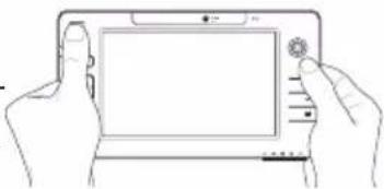
Refer to the diagram below to identify the components on this side of the UltraMobilePC.

1 Display Panel
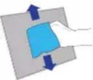
The display panel functions the same as a desktop monitor. The UltraMobilePC uses an active matrix TFT LCD, which provides excellent viewing like that of desktop monitors. Unlike desktop monitors, the LCD panel does not produce any radiation or flickering, so it is easier on the eyes. Use a soft cloth without chemical liquids (use plain water if necessary) to clean the display panel.
2 © Camera
The built-in camera allows picture taking or video recording. Can be used with video conferencing and other interactive applications.

③ Microphone (Built-in)
The built-in mono microphone can be used for video conferencing, voice narrations or simple audio recordings.

4 ◎ Thumbstick Cursor Control
The thumbstick cursor control with its left and right cursor buttons is a pointing device that provides the same functions as a desktop mouse.

5 Page Up & Page Down
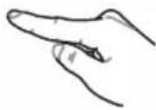
The Page Up and Page Down buttons act the same way as those on a keyboard.
6 UltraMobilePC Settings Button

The UltraMobilePC settings button bring up an easy menu to customize the UltraMobilePC to your desire.
7 Status Indicators

Status indicators represent various conditions. Details are described in section 3.
8 Audio Speaker
The built-in speaker system allows you to hear audio without additional attachments. The multimedia sound system features an integrated digital audio controller that produces rich, vibrant sound (results improved with external stereo headphones or speakers). Audio features are software controlled.

Microsoft Touch Pack Key
Pressing this button will launch a software built exclusively for UMPCs (Ultra Mobile Personal Computers) called Microsoft Touch Pack.
10 Direction & Enter Buttons
The direction (up/down/left/right) and Enter buttons act the same way as those on a keyboard.

11 Thumbstick Cursor Buttons
The thumbstick cursor control with its left and right cursor buttons is a pointing device that provides the same functions as a desktop mouse.

12 Fingerprint Scanner
The fingerprint scanner allows use of security software and using your fingerprint as your personal identification key instead of carrying security cards or remembering passwords.
Right Side
Refer to the diagram below to identify the components on this side of the UltraMobilePC.

1 品 LAN Port (disabled when using PortBar)
The RJ-45 LAN port with eight pins is larger than the RJ-11 modem port and supports a standard Ethernet cable for connection to a local network. The built-in connector allows convenient use without additional adapters.


Note: An active LAN cable must be connected in order for Windows device manager to detect the built-in LAN. For the same reason, an active LAN cable must be connected when installing a LAN driver.
② Expansion Port


The expansion port provides an easy-to-use PortBar docking solution to desktop peripherals and other accessories through a single connector.

Notes: (1) AC power adapter must be used. Cannot be used when UltraMobilePC is in battery mode. (2) Recommend using two AC power adapters (one on the UltraMobilePC and one on the PortBar) when using all ports on UltraMobilePC and PortBar. (3) Disables UltraMobilePC's LAN port when connected.
☐ Display (Monitor) Output (with provided adapter)
The provided VGA adapter for the expansion port will provide a 15-pin D-sub analog output to support a standard VGA-compatible device such as a monitor or projector to allow displaying on a larger external monitor.


USB Port (2.0/1.1)
The USB (Universal Serial Bus) port is compatible with USB 2.0 or USB 1.1 devices such as keyboards, pointing devices, cameras, hard disk drives, printers, and scanners connected in a series up to 12Mbits/sec (USB 1.1) and 480Mbits/sec (USB 2.0). USB allows many devices to run simultaneously on a single computer, with some peripherals acting as additional plug-in sites or hubs. USB supports hot-swapping of devices so that most peripherals can be connected or disconnected without restarting the computer.


Microphone Input Jack
The mono microphone jack (1/8 inch) can be used to connect an external microphone or output signals from audio devices. Using this jack automatically disables the built-in microphone. Use this feature for video conferencing, voice narrations, or simple audio recordings.


Headphone Output Jack
The stereo headphone jack (1/8 inch) is used to connect the UltraMobilePC's audio out signal to amplified speakers or headphones. Using this jack automatically disables the built-in speakers.


Power (DC) Input
The supplied power adapter converts AC power to DC power for use with this jack. Power supplied through this jack supplies power to the UltraMobilePC and charges the internal battery pack. To prevent damage to the UltraMobilePC and battery pack, always use the supplied power adapter. CAUTION: MAY BECOME WARM TO HOT WHEN IN USE. BE SURE NOT TO COVER THE ADAPTER AND KEEP IT AWAY FROM YOUR BODY.

Top Side
Refer to the diagram below to identify the components on this side of the UltraMobilePC.

1 AV-OUT AV-OUT
Audio/Video output port for connection to analog audio/video devices such as televisions or video recorders.

② USB Port (2.0/1.1)
The USB (Universal Serial Bus) port is compatible with USB 2.0 or USB 1.1 devices such as keyboards, pointing devices, cameras, hard disk drives, printers, and scanners connected in a series up to 12Mbits/sec (USB 1.1) and 480Mbits/sec (USB 2.0). USB allows many devices to run simultaneously on a single computer, with some peripherals acting as additional plug-in sites or hubs. USB supports hot-swapping of devices so that most peripherals can be connected or disconnected without restarting the computer.
3 HOLD Hold Key
When enabled, the buttons and the touchscreen will be disabled but the UltraMobilePC will continue to function (such as playing music).

4 Air Vents
The air vents allow cool air to enter and warm air to exit the system.

IMPORTANT! Make sure that paper, books, clothing, cables, or other jects do not block any of the air vents or else overheating may occur.
ob-

5 SD Memory Slot
This UltraMobilePC has a built-in SD memory card reader that can read SD flash memory cards from devices such as digital cameras, MP3 players, mobile phones, and PDAs. The built-in SD memory card reader is not only convenient but also faster than most external SD memory card readers.


Wireless Switch
Enables or disables the built-in wireless LAN and Bluetooth (selected models). When enabled, the wireless status indicator will light. Windows software settings are necessary before use.

7 LOGIN LOGIN Button
The LOGIN button sends a [Ctrl][Alt][Del] keyboard combination to the operating system to show Windows Security for logging in/off, locking, shutting down, showing task manager, or changing passwords. This special login feature is also known as Secure Attention Sequence (SAS).

8 POWER Power Switch
The power switch allows powering ON and OFF the UltraMobilePC and recovering from STD. Use the switch once to turn ON and once to turn OFF the UltraMobilePC. In Windows XP, this button can also be used to safely turn OFF the UltraMobilePC.
Left Side
Refer to the diagram below to identify the components on this side of the UltraMobilePC.

① ⇔ Mini-USB Port (Type A)
The mini-USB (Universal Serial Bus) port is for connection to the optional external USB keyboard.

② Wrist strap hook
The wrist strap hook is for use with the wrist strap to prevent accidentally dropping the UltraMobilePC when holding it in your hands.

Bottom Side
Refer to the diagram below to identify the components on this side of the UltraMobilePC.

Battery Lock - Spring
The spring battery lock is used to keep the battery pack secured. When the battery pack is inserted, it will automatically lock. To remove the battery pack, this spring lock must be held in the unlocked position.
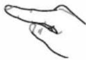
Battery Pack
The battery pack is automatically charged when the UltraMobilePC is connected to an AC power source and maintains power to the UltraMobilePC when AC power is not connected. This allows use when moving temporarily between locations. Battery time varies by usage and by the specifications for this UltraMobilePC. The battery pack cannot be disassembled and must be purchased as a single unit from an authorized retailer.
Battery Lock - Manual
The manual battery lock is used to keep the battery pack secured. Move the manual lock to the unlocked position to insert or remove the battery pack. Move the manual lock to the locked position after inserting the battery pack.

Back Side
Refer to the diagram below to identify the components on this side of the UltraMobilePC.

1 Battery Pack
The battery pack is automatically charged when the UltraMobilePC is connected to an AC power source and maintains power to the UltraMobilePC when AC power is not connected. This allows use when moving temporarily between locations. Battery time varies by usage and by the specifications for this UltraMobilePC. The battery pack cannot be disassembled and must be purchased as a single unit from an authorized retailer.
② GPS Antenna (built-in)
The GPS antenna can be flipped up for better reception or flipped down when not in use. The GPS antenna is used by the built-in SiRF3 GPS chipset. Together, the built-in GPS can be used with various navigation software applications without additional attachments.

3 Touchscreen Pen Compartment
This compartment allows storage of the pen used on the touchscree panel. Note: The touchscreen pen replicates cursor functions on the touchscreen and does not have electronic components.

3. Getting Started
Using AC Power
Using Battery Power
Powering ON the UltraMobilePC
Checking Battery Power
Restarting or Rebooting
Powering OFF the UltraMobilePC
Status Indicators

NOTE: Photos and icons in this manual are used for artistic purposes only and do not show what is actually used in the product itself.
Power System
Using AC Power

The UltraMobilePC power is comprised of two parts, the power adapter and the battery power system. The power adapter converts AC power from a wall outlet to the DC power required by the UltraMobilePC. Your Ultra-MobilePC comes with a universal AC-DC adapter. That means that you may connect the power cord to any 100V-120V as well as 220V-240V outlets without setting switches or using power converters. Different countries may require that an adapter be used to connect the provided US-standard AC power cord to a different standard. Most hotels will provide universal outlets to support different power cords as well as voltages. It is always best to ask an experienced traveler about AC outlet voltages when bringing power adapters to another country.


TIP: You can buy travel kits for the UltraMobilePC that includes power and modem adapters for almost every country.
With the AC power cord connected to the AC-DC converter, connect the AC power cord to an AC outlet (preferably with surge-protection) and then connect the DC plug to the Ultra-MobilePC. Connecting the AC-DC adapter to the AC outlet first allows you to test the AC outlet's power and the AC-DC converter itself for compatibility problems before connecting the DC power to the UltraMobilePC. The power indicator on the adapter (if available) will light if the power is within accepted ranges.

IMPORTANT! Damage may occur if you use a different adapter to power the UltraMobilePC or use the UltraMobilePC's adapter to power other electrical devices. If there is smoke, burning scent, or extreme heat coming from the AC-DC adapter, seek servicing. Seek servicing if you suspect a faulty AC-DC adapter. You may damage both your battery pack(s) and the UltraMobilePC with a faulty AC-DC adapter.

NOTE: This UltraMobilePC may come with either a two or three-prong plug depending on territory. If a three-prong plug is provided, you must use a grounded AC outlet or use a properly grounded adapter to ensure safe operation of the UltraMobilePC.

WARNING! THE POWER ADAPTER MAY BECOME WARM TO HOT WHEN IN USE. BE SURE NOT TO COVER THE ADAPTER AND KEEP IT AWAY FROM YOUR BODY.

Using Battery Power
The UltraMobilePC is designed to work with a removable battery pack. The battery pack consists of a set of battery cells housed together. A fully charged pack will provide several hours of battery life, which can be further extended by using power management features through the BIOS setup. Additional battery packs are optional and can be purchased separately through a retailer.
Installing and Removing the Battery Pack
Your UltraMobilePC may or may not have its battery pack installed. If your UltraMobilePC does not have its battery pack installed, use the following procedures to install the battery pack.

IMPORTANT! Never attempt to remove the battery pack while the UltraMobilePC is turned ON, as this may result in the loss of working data.
To install the battery pack: To remove the battery pack:


IMPORTANT! Only use battery packs and power adapters supplied with this UltraMobilePC or specifically approved by the manufacturer or retailer for use with this model or else damage may occur to the UltraMobilePC.

Battery Care
The UltraMobilePC's battery pack, like all rechargeable batteries, has a limit on the number times it can be recharged. The battery pack's useful life will depend on your environment temperature, humidity, and how your UltraMobilePC is used. It is ideal that the battery be used in a temperature range between 5°C and 35°C (41°F and 95°F). You must also take into account that the UltraMobilePC's internal temperature is higher than the outside temperature. Any temperatures above or below this range will shorten the life of the battery. But in any case, the battery pack's usage time will eventually decrease and a new battery pack must be purchased from an authorized dealer for this UltraMobilePC. Because batteries also have a shelf life, it is not recommended to buy extras for storing.

WARNING! For safety reasons, DO NOT throw the battery in fire, DO NOT short circuit the contacts, and DO NOT disassemble the battery. If there is any abnormal operation or damage to the battery pack caused by impact, turn OFF the UltraMobilePC and contact an authorized service center.

Powering ON the UltraMobilePC
The UltraMobilePC's power-ON message appears on the screen when you turn it ON. If necessary, you may adjust the brightness by using the hotkey. If you need to run the BIOS Setup to set or modify the system configuration, press [F2] upon bootup to enter the BIOS Setup. If you press [Tab] during the splash screen, standard boot information such as the BIOS version can be seen. Press [ESC] and you will be presented with a boot menu with selections to boot from your available drives.

NOTE: Before bootup, the display panel flashes when the power is turned ON. This is part of the UltraMobilePC's test routine and is not a problem with the display.

IMPORTANT! To protect the hard disk drive, always wait at least 5 seconds after turning OFF your UltraMobilePC before turning it back ON.

WARNING! DO NOT carry or cover a UltraMobilePC that is powered ON with any materials that will reduce air circulation such as a carrying bag.
The Power-On Self Test (POST)
When you turn ON the UltraMobilePC, it will first run through a series of software-controlled diagnostic tests called the Power-On Self Test (POST). The software that controls the POST is installed as a permanent part of the UltraMobilePC's architecture. The POST includes a record of the UltraMobilePC's hardware configuration, which is used to make a diagnostic check of the system. This record is created by using the BIOS Setup program. If the POST discovers a difference between the record and the existing hardware, it will display a message on the screen prompting you to correct the conflict by running BIOS Setup. In most cases the record should be correct when you receive the UltraMobilePC. When the test is finished, you may get a message reporting “No operating system found” if the hard disk was not preloaded with an operating system. This indicates that the hard disk is correctly detected and ready for the installation of a new operating system.
The S.M.A.R.T. (Self Monitoring and Reporting Technology) checks the hard disk drive during POST and gives a warning message if the hard disk drive requires servicing. If any critical hard disk drive warning is given during bootup, backup your data immediately and run Windows disk checking program. To run Window's disk checking program: (1) right-click any hard disk drive icon in "My Computer", (2) choose Properties, (3) click the Tools tab, (4) click Check Now, (5) select a hard disk drive, (6) select Thorough to also check for physical damages, and (7) click Start. Third party disk utilities such as Symantec's Norton Disk Doctor can also perform the same functions but with greater ease and more features.

IMPORTANT! If warnings are still given during bootup after running a software disk checking utility, you should take your UltraMobilePC in for servicing. Continued use may result in data loss.
Checking Battery Power
The battery system implements the Smart Battery standard under the Windows environment, which allows the battery to accurately report the amount of charge left in the battery. A fully-charged battery pack provides the Notebook PC a few hours of working power. But the actual figure varies depending on how you use the power saving features, your general work habits, the CPU, system memory size, and the size of the display panel.
Note: Screen captures shown here are examples only and may not reflect what you see in your system.
Right-click the battery icon
Cursor over the battery icon without power adapter.
Left-click the battery icon
Cursor over the battery icon with power adapter.
NOTE: You will be warned when battery power is low. If you continue to ignore the low battery warnings, the UltraMobilePC eventually enters suspend mode (Windows default uses STR).
Note: Screen captures shown here are examples only and may not reflect what you see in your system.
WARNING! Suspend-to-RAM (STR) does not last long when the battery power is depleted. Suspend-to-Disk (STD) is not the same as power OFF. STD requires a small amount of power and will fail if no power is available due to complete battery depletion or no power supply (e.g. removing both the power adapter and battery pack).
Charging the Battery Pack
Before you use your UltraMobilePC on the road, you will have to charge the battery pack. The battery pack begins to charge as soon as the UltraMobilePC is connected to external power using the power adapter. Fully charge the battery pack before using it for the first time. A new battery pack must completely charge before the UltraMobilePC is disconnected from external power. It takes a few hours to fully charge the battery when the UltraMobilePC is turned OFF and may take twice the time when the UltraMobilePC is turned ON. The battery charge light turns OFF when the battery pack is charged.

NOTE: The battery stops charging if the temperature is too high or the battery voltage is too high. BIOS provides a smart battery refreshing function. If the battery calibration process fails, stop charging and contact an authorized service center.

WARNING! Do not leave the battery pack discharged. The battery pack will discharge over time. If not using a battery pack, it must continued to be charged every three months to extend recovery capacity or else it may fail to charge in the future.
Power Options
The power switch turns ON and OFF the Notebook PC or putting the Notebook PC into sleep or hibernation modes. Actual behavior of the power switch can be customized in Windows Control Panel “Power Options.”
For other options, such as “Switch User, Restart, Sleep, or Shu Down,” click the arrowhead next to the lock icon.

Restarting or Rebooting
After making changes to your operating system, you may be prompted to restart the system. Some installation processes will provide a dialog box to allow restart. To restart the system manually, choose Restart.

IMPORTANT! To protect the hard drive, wait at least 5 seconds after turning OFF your UltraMobilePC before turning it back ON.
Emergency Shutdown
In case your operating system cannot properly turn OFF or restart, hold the power button
⊕ over 4 seconds.


IMPORTANT! Do not use emergency shutdown while data is being written; doing so can result in loss or destruction of your data.


Power Options
Power Management Modes
The Notebook PC has a number of automatic or adjustable power saving features that you can use to maximize battery life and lower Total Cost of Ownership (TCO). You can control some of these features through the Power menu in the BIOS Setup. ACPI power management settings are made through the operating system. The power management features are designed to save as much electricity as possible by putting components into a low power consumption mode as often as possible but also allow full operation on demand.

Sleep and Hibernate
Power management settings can be found in the Windows > Control Panel > Power Options. In System Settings, you can define “Sleep/Hibernate” or “Shut Down” for closing the display panel or pressing the power button. “Sleep” and “Hibernate” saves power when your Notebook PC is not in use by turning OFF certain components. When you resume your work, your last status (such as a document scrolled down half way or email typed half way) will reappear as if you never left. “Shut Down” will close all applications and ask if you want to save your work if any are not saved.

Thermal Power Control
There are three power control methods for controlling the Notebook PC's thermal state. These power control cannot be configured by the user and should be known in case the Notebook PC should enter these states. The following temperatures represent the chassis temperature (not CPU). - The fan turns ON for active cooling when the temperature reaches the safe upper limit. - The CPU decreases speed for passive cooling when the temperature exceeds the safe upper limit. - The system shut down for critical cooling when temperature exceeds the maximum safe upper limit.Status Indicators
  Power Indicator
The power indicator lights when the UltraMobilePC is turned ON and blinks slowly when the UltraMobilePC is in the Suspend-to-RAM (Standby) mode. This indicator is OFF when the UltraMobilePC is turned OFF or in the Suspend-to-Disk (Hibernation) mode. Battery Charge Indicator
 The battery charge indicator shows the status of the battery's power as follows: ON: The UltraMobilePC's battery is charging when AC power is connected. OFF: The UltraMobilePC's battery is charged or completely drained. Blinking: Battery power is less than 10% and the AC power is not connected. Drive Activity Indicator
 Indicates that the UltraMobilePC is accessing one or more storage device(s) such as the hard disk. The light flashes proportional to the access time. Wireless LAN Indicator
 When the built-in wireless LAN is enabled, this indicator will light. (Windows software settings are necessary to use this function.) Bluetooth Indicator
 This is only applicable on models with internal Bluetooth. This indicator will light to show that the UltraMobilePC's built-in Bluetooth function is activated.4. Using the UltraMobilePC
Display Calibration Connections Network Connection Wireless LAN Connection Bluetooth Wireless Connection Power Management Modes Fingerprint Scanner GPS Software  NOTE: Photos and icons in this manual are used for artistic purposes only and do not show what is actually used in the product itself. Display Calibration (Vista)
 1. Launch Control Panel from Windows Start.  2. Double click Tablet PC Settings icon.  3. Click the Calibrate button on the "General"4. page.  Carefully tap the center of each cross hair that appears to complete the calibration process. Display Calibration (XP)
 1. Double click the TouchSet Utility icon on the desktop.  2. Or launch TouchSet Utility through Windows Start.  3. Click the Calibration tab and click the Calibrating Now button.  4. Carefully tap the center of each cross hair that appears to complete the calibration process.Connections
Network Connection
Connect a network cable, with RJ-45 connectors on each end, to the modem/network port on the Notebook PC and the other end to a hub or switch. For 100 BASE-TX / 1000 BASE-T speeds, your network cable must be category 5 or better (not category 3) with twisted-pair wiring. If you plan on running the interface at 100/1000Mbps, it must be connected to a 100 BASE-TX / 1000 BASE-T hub (not a BASE-T4 hub). For 10Base-T, use category 3, 4, or 5 twisted-pair wiring. 10/100 Mbps Full-Duplex is supported on this Notebook PC but requires connection to a network switching hub with “duplex” enabled. The software default is to use the fastest setting so no user-intervention is required.  1000BASE-T (or Gigabit) is only supported on selected models.Twisted-Pair Cable
The cable used to connect the Ethernet card to a host (generally a Hub or Switch) is called a straight-through Twisted Pair Ethernet (TPE). The end connectors are called RJ-45 connectors, which are not compatible with RJ-11 telephone connectors. If connecting two computers together without a hub in between a crossover LAN cable is required (Fast-Ethernet model). (Gigabit models support auto-crossover so a crossover LAN cable is optional.)   Example of the Notebook PC connected to a Network Hub or Switch for use with the built-in Ethernet controller.  Network cable with RJ-45 connectors Wireless LAN Connection (on selected models)
The optional built-in wireless LAN is a compact easy-to-use wireless Ethernet adapter. Implementing the IEEE 802.11 standard for wireless LAN (WLAN), the optional built-in wireless LAN is capable of fast data transmission rates using Direct Sequence Spread Spectrum (DSSS) and Orthogonal Frequency Division Multiplexing (OFDM) technologies on 2.4GHz/5GHz frequencies. The optional built-in wireless LAN is backward compatible with the earlier IEEE 802.11 standard allowing seamless interfacing of wireless LAN standards. The optional built-in wireless LAN is a client adapter that supports Infrastructure and Ad-hoc mod giving you flexibility on your existing or future wireless network configurations for distances up to 40 meters between the client and the access point. To provide efficient security to your wireless communication, the optional built-in wireless LAN comes with a 64-bit/128-bit Wired Equivalent Privacy (WEP) encryption and Wi-Fi Protected Access (WPA) features. These are examples of the Notebook PC connected to a Wireless Network. Ad-hoc mode
The Ad-hoc mode allows the Notebook PC to connect to another wireless device. No access point (AP) is required in this wireless environment. (All devices must install optional 802.11 wireless LAN adapters.)  Infrastructure mode
The Infrastructure mode allows the Notebook PC and other wireless devices to join a wireless network created by an Access Point (AP) (sold separately) that provides a central link for wireless clients to communicate with each other or with a wired network. (All devices must install optional 802.11 wireless LAN adapters.) Windows Wireless Network Connection Connecting to a network (Vista)
 1. Press [WIRELESS] switch repeatedly until Wireless LAN ON or WLAN & Bluetooth ON is shown.  1b. Or double click the Wireless Console icon on the taskbar and select either the 1st icon to activate both Wireless & Bluetooth, or select the 2nd icon for Wireless activation only.  2. You should see the "Not Connected" network icon.  3. Right click on the network icon and select Connect to a network.  4. Select "Show Wireless" if you have many networks in your area.  5. Select the wireless network you want to connect to.  7. After connection has been established, "Connected" will be shown.Windows Wireless Network Connection Connecting to a network (XP)
Using Windows XP wireless settings require that you select this option in the ASUS WLAN Control Center.  ASUS WLAN Control Center   1. Press [WIRELESS] switch repeatedly until Wireless LAN ON or WLAN & Bluetooth ON is shown.  1b. Or double click the Wireless Console icon on the taskbar and click on the 1st icon to activate both Wireless & Bluetooth, or select the 2nd icon for Wireless activation only.  2. Double click the WLAN icon on the taskbar.  3. Select Refresh network list from the left side menu and a list of available network within your area and its signal strength will show. Select your network and click on Connect.  4. When connecting, you may have to enter a password.  5. After connection has been established, "Connected" will be shown on the right side above the signal strength indicator.ASUS Wireless LAN (on selected models)
Connecting to a network
Using ASUS wireless settings require that you select this option in the ASUS WLAN Control Center.    1. Press [WIRELESS] switch repeatedly until Wireless LAN ON or WLAN & Bluetooth ON is shown.  1b. Or double click the Wireless Console icon on the taskbar and click on the 1st icon to activate both Wireless & Bluetooth, or select the 2nd icon for Wireless activation only.   2. Double click the icon on the desktop or click3. On the left hand side menu, click Survey Start I Programs | ASUS Utility | WLAN Card to start scanning for available networks in your area | ASUS WLAN Control Center.   4. The list will show all available networks within If the selected Network has security settings, your area. Select the network you want and you may be required to enter a password. click Connect.ASUS Wireless LAN (on selected models) Connecting to a network (cont.)
 6. Click the Encryption tab to configure the Network Authentication mode and Password.  7. The Status tab will show connection status and details.  Note: Click "Save Configuration" and "Save" to remember settings for this network.Bluetooth Wireless Connection (on selected models)
Notebook PCs with Bluetooth technology eliminates the need for cables for connecting Bluetooth-enabled devices. Examples of Bluetooth-enabled devices may be Notebook PCs, Desktop PCs, mobile phones, and PDAs.  Note: If your Notebook PC did not come with built-in Bluetooth, you need to connect a USB or ExpressCard Bluetooth module in order to use Bluetooth.Bluetooth-enabled mobile phones
You can wireless connect to your mobile phone. Depending on your mobile phone's capabilities, you can transfer phone book data, photos, sound files, etc. or use it as a modem to connect to the Internet. You may also use it for SMS messaging. Bluetooth-enabled computers or PDAs
You can wireless connect to another computer or PDA and exchange files, share peripherals, or share Internet or network connections. You may also make use of Bluetooth-enabled wireless keyboard or mouse. Turning ON and Launching Bluetooth Utility (Vista)
This process can be used to add most Bluetooth devices. See Appendix for complete process.  Wireless LAN OK  WLAN & Bluetooth ON  WIRELESS LAN + BLWETOOTH 1. Press [WIRELESS] switch repeatedly until Bluetooth ON or WLAN & Bluetooth ON is shown. 1b. Or double click the Wireless Console icon on the taskbar and select either the 1st icon to activate both Wireless & Bluetooth, or select the 3rd icon for Bluetooth activation only.  2. Select Add a Bluetooth Device on the taskbar men.  2b. Or Launch Bluetooth Devices from the Windows Control Panel.Fingerprint Registration (on selected models)
The fingerprint scanner can be used for instant and secure user authentication. These instructions will show you how to setup the fingerprint registration.    1. This wizard will automatically start when2. Select "Fingerprints" and click Next. TPM is enabled in BIOS after setting security passwords. Click Next to continue.   3. Select a finger on the diagram. Swipe the 4. You must register at least two fingers to corresponding finger on the scanner slowly. decrease the chance of problems. You must swipe your finger multiple times for verification. Fingerprint Registration (on selected models) cont.
  5. Select a finger on the diagram and swipe 6. Click Finish when done. the corresponding finger on the scanner slowly. You must swipe your finger multiple times for verification. You must register at least two fingers to decrease the chance of any problems.   7. Right-click the icon on the taskbar and 8. Select "General Options" and "Single Sign select "Settings and Options". On" and configure your preferences.GPS Software
The included software may be used with the built-in GPS system. Choose Tools | GPS | Configure GPS Receiver..., select COM2, and click OK.  Select Tools | GPS | Start GPS Tracking. The GPS Sensor will acquire information for these fields once a satellite fix is acquired. UltraMobilePC
Appendix
Optional Accessories Optional Connections Glossary Declarations and Safety Statements UltraMobilePC Information  NOTE: Photos and icons in this manual are used for artistic purposes only and do not show what is actually used in the product itself.Optional Accessories
These items, if desired, come as optional items to complement your UltraMobilePC. Foldable USB Keyboard   Slide latch on the top to lock the keyboard in the open position.  Extend: Pull the USB connectors apart (not fully) to extend the mini-USB cable. (Note: If you pull too much, it will retract.)  Retract: Pull the USB connectors fully apart and allow the internal spring to automatically retract the mini-USB cable.  Connect the mini-USB cable to the foldable USB keyboard (left side) and the mini-USB port on the UltraMobilePC (left side).PortBar
 Notes: (1) AC power adapter must be used. Cannot be used when UltraMobilePC is in battery mode. (2) Recommend using two AC power adapters (one on the UltraMobilePC and one on the PortBar) when using all ports on UltraMobilePC and PortBar. (3) Disables UltraMobilePC's LAN port when connected. 1 □ Display (Monitor) Output (with provided adapter)
The provided VGA adapter for the expansion port will provide a 15-pin D-sub analog output to support a standard VGA-compatible device such as a monitor or projector to allow displaying on a larger external monitor. ② SPDIF Output Jack (SPDIF Output)
This jack provides connection to SPDIF (Sony/Philips Digital Interface) compliant devices for digital audio output. Use this feature to turn the UltraMobilePC into a hi-fi home entertainment system. 3 品 LAN Port (disabled when using PortBar)
The RJ-45 LAN port with eight pins is larger than the RJ-11 modem port and supports a standard Ethernet cable for connection to a local network. The built-in connector allows convenient use without additional adapters. 4 USB Port (2.0/1.1)
The USB (Universal Serial Bus) port is compatible with USB 2.0 or USB 1.1 devices such as keyboards, pointing devices, cameras, hard disk drives, printers, and scanners connected in a series up to 12Mbits/sec (USB 1.1)  and 480Mbits/sec (USB 2.0). USB allows many devices to run simultaneously on a single computer, with some peripherals acting as additional plug-in sites or hubs. USB supports hot-swapping of devices so that most peripherals can be connected or disconnected without restarting the computer.PortBar (Cont.)
 Plug the PortBar to the expansion port.  Keep the PortBar connector in the keeper when not in use to protect the contacts.  Plug the UltraMobilePC's power adapter into this power port so that you can easily free the UltraMobilePC from all your peripherals with just one connector.  WARNING! You must plug the power adapter into the UltraMobilePC or PortBar when you use PortBar. The PortBar must not be used when the UltraMobilePC is operating in battery mode.More Optional Accessories
These items, if desired, come as optional items to complement your UltraMobilePC.USB Hub (Optional)
Attaching an optional USB hub will increase your USB ports and allow you to quickly connect or disconnect many USB peripherals through a single cable. USB Flash Memory Disk
A USB flash memory disk is an optional item that can replace the 1.44MB floppy disk and provide storage up to several hundred megabytes, higher transfer speeds, and greater durability. When used in current operating systems, no drivers are necessary. USB Floppy Disk Drive
An optional USB-interface floppy disk drive can accept a standard 1.44MB (or 720KB) 3.5-inch floppy diskette.  WARNING! To prevent system failures, use Windows “Safely Remove Hardware” on the taskbar before disconnecting the USB floppy disk drive. Eject the floppy disk before transporting the Notebook PC to prevent damage from shock.  DCIN Vehicle Power Adapter
The vehicle power adapter provides a source of power for using the Notebook PC and/or charging the Notebook PC's battery pack while in transit when no AC power is available. This product is an essential tool for today's mobile professional. Your purchase will enhance the power, performance, and versatility of your portable computer while traveling on the road or on the sea. The Vehicle Power Adapter can be used in vehicles or boats using a standard cigarette lighter socket. The Vehicle Power Adapter accepts input ranges from 10.8VDC (Volts - Direct Current) to 16VDC and provides 19VDC up to 120W (Watts). Optional Connections
These items, if desired, may be purchased from third-parties.Printer Connection
One or more USB printers can be simultaneously used on any USB port or USB hub.  Bluetooth Mouse Setup (optional)
This process can be used to add most Bluetooth devices in Windows operating system.   1. Press [WIRELESS] switch repeatedly until Bluetooth ON or WLAN & Bluetooth ON is shown.  1b. Or double click the Wireless Console icon on the taskbar and select either the 1st icon to activate both Wireless & Bluetooth, or select the 3rd icon for Bluetooth activation only.  2. Select Add a Bluetooth Device on the taskbar menu.  2b. Or Launch Bluetooth Devices from the Windows Control Panel.  2c. If launched from the Control Panel, click Add from this screen.  3. Prepare the Bluetooth mouse. • Install two "AA" batteries. - Turn ON the power switch on the bottom of the mouse. The bottom sensor should glow red. - Push the "RESET" button on the bottom of the Bluetooth mouse. Bluetooth Mouse Setup (optional) cont.
 4. Click Next when the Bluetooth mouse is ready.  5. A list of nearby Bluetooth devices will be shown. Select the Bluetooth mouse and click Next.  6. Select "Don't use a passkey" and click Next.  7. Wait while the Bluetooth mouse is being added.  8. Click Finish when adding is complete.  9. You will see your device in the window. You can also add or remove Bluetooth devices here.  Note: “RESET” may be necessary after changing batteries. Repeat steps if necessary.Operating System and Software
This Notebook PC may offer (depending on territory) its customers the choice of a pre-installed Microsoft Windows operating system. The choices and languages will depend on the territory. The levels of hardware and software support may vary depending on the installed operating system. The stability and compatibility of other operating systems cannot be guaranteed. Support Software
This Notebook PC comes with a support disc that provides BIOS, drivers and applications to enable hardware features, extend functionality, help manage your Notebook PC, or add functionality not provided by the native operating system. If updates or replacement of the support disc is necessary, contact your dealer for web sites to download individual software drivers and utilities.  The support disc contains all drivers, utilities and software for all popular operating systems including those that have been pre-installed. The support disc does not include the operating system itself. The support disc is necessary even if your Notebook PC came pre-configured in order to provide additional software not included as part of the factory pre-install. A recovery disc is optional and includes an image of the original operating system installed on the hard drive at the factory. The recovery disc provides a comprehensive recovery solution that quick restores the Notebook PC's operating system to its original working state provided that your hard disk drive is in good working order. Contact your retailer if you require such a solution.  Note: Some of the Notebook PC's components and features may not work until the device drivers and utilities are installed.Glossary
ACPI (Advanced Configuration and Power Management Interface)
Modern standard for reducing power usage in computers.APM (Advanced Power Management)
Modern standard for reducing power usage in computers.AWG (American Wire Gauge)
 NOTE: This table is for general reference only and should not be used as a source of the American Wire Gauge standard as this table may not be current or complete.| Gauge Diam Area R I@3A/mm2AWG (mm) (mm2) (ohm/km) (mA) | ||||||||||||||||||||||||||||||||||||||||||||||||||||||||||||||||||||||||||||||||||||||||||||||||||||||||
| 33 | 0.18 | 0.026 | 676 | 75 | ||||||||||||||||||||||||||||||||||||||||||||||||||||||||||||||||||||||||||||||||||||||||||||||||||||
| 0.19 | 0.028 | 605 | 85 | |||||||||||||||||||||||||||||||||||||||||||||||||||||||||||||||||||||||||||||||||||||||||||||||||||||
BIOS (Basic Input/Output System)
BIOS is a set of routines that affect how the computer transfers data between computer components, such as memory, disks, and the display adapter. The BIOS instructions are built into the computer's read-only memory. BIOS parameters can be configured by the user through the BIOS Setup program. The BIOS can be updated using the provided utility to copy a new BIOS file into the EEPROM.Bit (Binary Digit)
Represents the smallest unit of data used by the computer. A bit can have one of two values: 0 orBoot
Boot means to start the computer operating system by loading it into system memory. When the manual instructs you to “boot” your system (or computer), it means to turn ON your computer. “Reboot” means to restart your computer. When using Windows 95 or later, selecting “Restart” from “Start | Shut Down...” will reboot your computer.Bluetooth (on selected models)
Bluetooth is a short-range wireless technology that lets you connect computers, mobile phones, and handheld devices to each other and to the Internet. Bluetooth technology eliminates the need for the cables that connect devices together. Bluetooth-enabled devices connect wirelessly within a 10 m range.Byte (Binary Term)
One byte is a group of eight contiguous bits. A byte is used to represent a single alphanumeric character, punctuation mark, or other symbol.Clock Throttling
Chipset function which allows the processor's clock to be stopped and started at a known duty cycle. Clock throttling is used for power savings, thermal management, and reducing processing speed.CPU (Central Processing Unit)
The CPU, sometimes called “Processor,” actually functions as the “brain” of the computer. It interprets and executes program commands and processes data stored in memory.Driver
A device driver is a special set of software instructions that allows the computer's operating system to communicate with hardware devices such as VGA, audio, Ethernet, printer, or modem. Usually a driver is supplied with the corresponding hardware device.DVD (Digital Versatile Disk)
DVD is essentially a bigger, faster CD that can hold video as well as audio and computer data with the same physical dimension. With these capacities and access rates, DVD discs can provide you with dramatically-enhanced high-color, full-motion videos, better graphics, sharper pictures, and digital audio for a theater-like experience. DVD aims to encompass home entertainment, compute and business information with a single digital format, eventually replacing audio CD, videotape, laserdisc, CD-ROM, and video game cartridges. To view DVD, a DVD drive is required.Hardware
Hardware is a general term referring to the physical components of a computer system, including peripherals such as printers, modems, and pointing devices.Hibernation Mode
A power mode that saves all data in memory to the hard disk and turns the CPU and hard disk off. When canceling Hibernation Mode, all application programs that were running are restored to their last state.IDE (Integrated Drive Electronics)
IDE devices integrate the drive control circuitry directly on the drive itself, eliminating the need for a separate adapter card (in the case for SCSI devices). UltraDMA/66 or 100 IDE devices can achieve up to 33MB/Sec transfer.POST (Power On Self Test)
When you turn on the computer, it will first run through the POST, a series of software-controlled diagnostic tests. The POST checks system memory, the motherboard circuitry, the display, the keyboard, the diskette drive, and other I/O devices.RAM (Random Access Memory)
RAM (usually just called memory) is the place in a computer where the operating system, application programs, and data in current use are temporarily kept so that they can be quickly reached by the computer's processor instead of having to read from and write to slower storage such as the hard disk or optical disc.Standby Mode
A power mode that enables a computer to save power consumption while not in use. When a computer is in Standby Mode, the data on the computer memory is not saved onto the hard disk. If the power is tuned off, the data in memory will be lost.Suspend Mode
In Save-to-RAM (STR) and Save-to-Disk (STD), the CPU clock is stopped and most of the UltraMobilePC devices are put in their lowest active state. The UltraMobilePC enters Suspend when the system remains idle for a specified amount of time or manually using the function keys. The time-out setting of both Hard Disk and Video can be set by the BIOS Setup. The Power LED blinks when the UltraMobilePC is in STR mode. In STD mode, the UltraMobilePC will appear to be powered OFF.System Disk
A system disk contains the core file of an operating system and is used to boot up the operating system.Twisted-Pair Cable
The cable used to connect the Ethernet card to a host (generally a Hub or Switch) is called a straig through Twisted Pair Ethernet (TPE). The end connectors are called RJ-45 connectors, which are not compatible with RJ-11 telephone connectors. If connecting two computers together without a hub in between, a crossover twisted-pair is required.UltraDMA/66 or 100
UltraDMA/66 or 100 are new specifications to improve IDE transfer rates. Unlike traditional PIO mode, which only uses the rising edge of IDE command signal to transfer data, UltraDMA/66 or 100 uses both rising edge and falling edge.USB (Universal Serial Bus)
A new 4-pin serial peripheral bus that allows plug and play computer peripherals such as keyboard mouse, joystick, scanner, printer and modem/ISDN to be automatically configured when they are attached physically without having to install drivers or reboot. With USB, the traditional complex cables from back panel of your computer can be eliminated.Windows
The name of the operating system developed by Microsoft Corporation and used on this computer.Certifications
Federal Communications Commission Statement
This device complies with FCC Rules Part 15. Operation is subject to the following two conditions: • This device may not cause harmful interference, and - This device must accept any interference received, including interference that may cause undesired operation. This equipment has been tested and found to comply with the limits for a class B digital device, pursuant to Part 15 of the Federal Communications Commission (FCC) rules. These limits are designed to provide reasonable protection against harmful interference in a residential installation. This equipment generates, uses, and can radiate radio frequency energy and, if not installed and used in accordance with the instructions, may cause harmful interference to radio communications. However, there is no guarantee that interference will not occur in a particular installation. If this equipment does cause harmful interference to radio or television reception, which can be determined by turning the equipment off and on, the user is encouraged to try to correct the interference by one or more of the following measures: - Reorient or relocate the receiving antenna. - Increase the separation between the equipment and receiver. - Connect the equipment into an outlet on a circuit different from that to which the receiver is connected. - Consult the dealer or an experienced radio/TV technician for help.  WARNING! The use of a shielded-type power cord is required in order to meet FCC emission limits and to prevent interference to the nearby radio and television reception. It is essential that only the supplied power cord be used. Use only shielded cables to connect I/O devices to this equipment. You are cautioned that changes or modifications not expressly approved by the party responsible for compliance could void your authority to operate the equipment. (Reprinted from the Code of Federal Regulations #47, part 15.193, 1993. Washington DC: Office of the Federal Register, National Archives and Records Administration, U.S. Government Printing Office.)FCC Radio Frequency Interference Requirements
This device is restricted to INDOOR USE due to its operation in the 5.15 to 5.25GHz frequency range. FCC requires this product to be used indoors for the frequency range 5.15 to 5.25GHz to reduce the potential for harmful interference to co-channel of the Mobile Satellite Systems. High power radars are allocated as primary user of the 5.25 to 5.35GHz and 5.65 to 5.85GHz bands. These radar stations can cause interference with and / or damage this device.  IMPORTANT: This device and its antenna(s) must not be co-located or operating in conjunction with any other antenna or transmitter.FCC Radio Frequency (RF) Exposure Caution Statement
This equipment complies with FCC radiation exposure limits set forth for an uncontrolled environment. To maintain compliance with FCC RF exposure compliance requirements, please avoid direct contact to the transmitting antenna during transmitting. End users must follow the specific operating instructions for satisfying RF exposure compliance. For operation within 5.15GHz and 5.25GHz frequency ranges, it is restricted to indoor environment, and the antenna of this device must be integral.  FCC Caution: Any changes or modifications not expressly approved by the party responsible for compliance could void the user's authority to operate this equipment. "The manufacture declares that this device is limited to Channels 1 through 11 in the 2.4GHz frequency by specified firmware controlled in the USA."Declaration of Conformity (R&TTE directive 1999/5/EC)
The following items were completed and are considered relevant and sufficient: • Essential requirements as in [Article 3] - Protection requirements for health and safety as in [Article 3.1a] - Testing for electric safety according to [EN 60950] - Protection requirements for electromagnetic compatibility in [Article 3.1b] - Testing for electromagnetic compatibility in [EN 301 489-1] & [EN 301] - Testing according to [489-17] • Effective use of the radio spectrum as in [Article 3.2] • Radio test suites according to [EN 300 328-2]CE Mark Warning
This is a Class B product, in a domestic environment, this product may cause radio interference, in which case the user may be required to take adequate measures.IC Radiation Exposure Statement for Canada
This equipment complies with IC radiation exposure limits set forth for an uncontrolled environment. To maintain compliance with IC RF exposure compliance requirements, please avoid direct contact to the transmitting antenna during transmitting. End users must follow the specific operating instructions for satisfying RF exposure compliance. Operation is subject to the following two conditions: • This device may not cause interference and - This device must accept any interference, including interference that may cause undesired operation of the device. To prevent radio interference to the licensed service (i.e. co-channel Mobile Satellite systems) this device is intended to be operated indoors and away from windows to provide maximum shielding. Equipment (or its transmit antenna) that is installed outdoors is subject to licensing. Because high power radars are allocated as primary users (meaning they have priority) in 5250-5350 MHz, these radars could cause interference and/or damage to license exempt LAN devices.Wireless Operation Channel for Different Domains
N. America 2.412-2.462 GHz Ch01 through CH11 Japan 2.412-2.484 GHz Ch01 through Ch14 Europe ETSI 2.412-2.472 GHz Ch01 through Ch13France Restricted Wireless Frequency Bands
Some areas of France have a restricted frequency band. The worst case maximum authorized power indoors are: - 10mW for the entire 2.4 GHz band (2400 MHz–2483.5 MHz) • 100mW for frequencies between 2446.5 MHz and 2483.5 MHz  NOTE: Channels 10 through 13 inclusive operate in the band 2446.6 MHz to 2483.5 MHz. There are few possibilities for outdoor use: On private property or on the private property of public persons, use is subject to a preliminary authorization procedure by the Ministry of Defense, with maximum authorized power of 100mW in the 2446.5–2483.5 MHz band. Use outdoors on public property is not permitted. In the departments listed below, for the entire 2.4 GHz band: • Maximum authorized power indoors is 100mW • Maximum authorized power outdoors is 10mW Departments in which the use of the 2400–2483.5 MHz band is permitted with an EIRP of less than 100mW indoors and less than 10mW outdoors: 01 Ain Orientales 02 Aisne 03 Allier 05 Hautes Alpes 08 Ardennes 09 Ariège 11 Aude 12 Aveyron 16 Charente 24 Dordogne 25 Doubs 26 Drôme 32 Gers 36 Indre 37 Indre et Loire 41 Loir et Cher 45 Loiret 50 Manche 55 Meuse 58 Nièvre 59 Nord 60 Oise 61 Orne 63 Puy du Dôme 64 Pyrénées Atlantique 66 Pyrénées 67 Bas Rhin 68 Haut Rhin 70 Haute Saône 71 Saône et Loire 75 Paris 82 Tarn et Garonne 84 Vaucluse 88 Vosges 89 Yonne 90 Territoire de Belfort 94 Val de Marne This requirement is likely to change over time, allowing you to use your wireless LAN card in more areas within France. Please check with ART for the latest information (www.art-telecom.fr)  NOTE: Your WLAN Card transmits less than 100mW, but more than 10mW.UL Safety Notices
Required for UL 1459 covering telecommunications (telephone) equipment intended to be electrically connected to a telecommunication network that has an operating voltage to ground that does not exceed 200V peak, 300V peak-to-peak, and 105V rms, and installed or used in accordance with the National Electrical Code (NFPA 70). When using the UltraMobilePC modem, basic safety precautions should always be followed to reduce the risk of fire, electric shock, and injury to persons, including the following: - Do not use the UltraMobilePC near water, for example, near a bath tub, wash bowl, kitchen sink or laundry tub, in a wet basement or near a swimming pool. - Do not use the UltraMobilePC during an electrical storm. There may be a remote risk of electric shock from lightning. - Do not use the UltraMobilePC in the vicinity of a gas leak. Required for UL 1642 covering primary (non-rechargeable) and secondary (rechargeable) lithium batteries for use as power sources in products. These batteries contain metallic lithium, or a lithium alloy, or a lithium ion, and may consist of a single electrochemical cell or two or more cells connected in series, parallel, or both, that convert chemical energy into electrical energy by an irreversible or reversible chemical reaction. - Do not dispose the UltraMobilePC battery pack in a fire, as they may explode. Check with local codes for possible special disposal instructions to reduce the risk of injury to persons due to fire or explosion. - Do not use power adapters or batteries from other devices to reduce the risk of injury to persons due to fire or explosion. Use only UL certified power adapters or batteries supplied by the manufacturer or authorized retailers.Power Safety Requirement
Products with electrical current ratings up to 6A and weighing more than 3Kg must use approved power cords greater than or equal to: H05VV-F, 3G, 0.75mm 2 or H05VV-F, 2G, 0.75mm 2 .Nordic Lithium Cautions (for lithium-ion batteries)
CAUTION! Danger of explosion if battery is incorrectly replaced. Replace only with the same or equivalent type recommended by the manufacturer. Dispose of used batteries according to the manufacturer's instructions. (English) ATTENZIONE! Rischio di esplosione della batteria se sostituita in modo errato. Sostituire la batteria con un una di tipo uguale o equivalente consigliata dalla fabbrica. Non disperdere le batterie nell'ambiente. (Italian) VORSICHT! Explosionsgetahr bei unsachgemäßen Austausch der Batterie. Ersatz nur durch denselben oder einem vom Hersteller empfohlenem ähnlichen Typ. Entsorgung gebrauchter Batterien nach Angaben des Herstellers. (German) ADVARSELI! Lithiumbatteri - Eksplosionsfare ved fejlagtig håndtering. Udskiftning må kun ske med batteri af samme fabrikat og type. Levér det brugte batteri tilbage til leverandøren. (Danish) WARNING! Explosionsfara vid felaktigt batteribyte. Använd samma batterityp eller en ekvivalent typ som rekommenderas av apparattillverkaren. Kassera använt batteri enligt fabrikantens instruktion. (Swedish) VAROITUS! Paristo voi räjähtää, jos se on virheellisesti asennettu. Vaihda paristo ainoastaan laitevalmistajan sousittelemaan tyyppiin. Hävitä käytetty paristo valmistagan ohjeiden mukaisesti. (Finnish) ATTENTION! Il y a danger d'explosion s'il y a remplacement incorrect de la batterie. Remplacer uniquement avec une batterie du mère type ou d'un type équivalent recommandé par le constructeur. Mettre au rebut les batteries usagées conformément aux instructions du fabricant. (French) ADVARSEL! Eksplosjonsfare ved feilaktig skifte av batteri. Benytt samme batteritype eller en tilsvarende type anbefalt av apparatfabrikanten. Brukte batterier kasseres i henhold til fabrikantens instruksjoner. (Norwegian) 標準品以外の使用は、危険の元になります。交換品を使用する場合、製造者に指定されるものを使って下さい。製造者の指示に従って処理して下さい。(Japanese)


- ULTRAMOBILEPC (UMPC)
- HARDWARE USER'S MANUAL
- TABLE OF CONTENTS
- INTRODUCING THE ULTRAMOBILEPC
- KNOWING THE PARTS
- GETTING STARTED
- USING THE ULTRAMOBILEPC
- APPENDIX
- ULTRAMOBILEPC
- ABOUT THIS USER'S MANUAL
- NOTES FOR THIS MANUAL
- SAFETY PRECAUTIONS
- TRANSPORTATION PRECAUTIONS
- COVER YOUR ULTRAMOBILEPC
- CHARGE YOUR BATTERIES
- AIRPLANE PRECAUTIONS
- PREPARING YOUR ULTRAMOBILEPC
- FRONT SIDE
- DISPLAY PANEL
- © CAMERA
- ③ MICROPHONE (BUILT-IN)
- ◎ THUMBSTICK CURSOR CONTROL
- PAGE UP & PAGE DOWN
- ULTRAMOBILEPC SETTINGS BUTTON
- STATUS INDICATORS
- AUDIO SPEAKER
- MICROSOFT TOUCH PACK KEY
- DIRECTION & ENTER BUTTONS
- THUMBSTICK CURSOR BUTTONS
- FINGERPRINT SCANNER
- RIGHT SIDE
- 品 LAN PORT (DISABLED WHEN USING PORTBAR)
- ② EXPANSION PORT
- ☐ DISPLAY (MONITOR) OUTPUT (WITH PROVIDED ADAPTER)
- USB PORT (2.0/1.1)
- MICROPHONE INPUT JACK
- HEADPHONE OUTPUT JACK
- POWER (DC) INPUT
- TOP SIDE
- AV-OUT AV-OUT
- ② USB PORT (2.0/1.1)
- HOLD HOLD KEY
- AIR VENTS
- SD MEMORY SLOT
- WIRELESS SWITCH
- LOGIN LOGIN BUTTON
- POWER POWER SWITCH
- LEFT SIDE
- ① ⇔ MINI-USB PORT (TYPE A)
- ② WRIST STRAP HOOK
- BOTTOM SIDE
- BATTERY LOCK - SPRING
- BATTERY PACK
- BATTERY LOCK - MANUAL
- BACK SIDE
- ② GPS ANTENNA (BUILT-IN)
- TOUCHSCREEN PEN COMPARTMENT
- POWER SYSTEM
- USING AC POWER
- USING BATTERY POWER
- INSTALLING AND REMOVING THE BATTERY PACK
- BATTERY CARE
- POWERING ON THE ULTRAMOBILEPC
- THE POWER-ON SELF TEST (POST)
- CHECKING BATTERY POWER
- CHARGING THE BATTERY PACK
- POWER OPTIONS
- RESTARTING OR REBOOTING
- EMERGENCY SHUTDOWN
- POWER MANAGEMENT MODES
- SLEEP AND HIBERNATE
- THERMAL POWER CONTROL
- POWER INDICATOR
- BATTERY CHARGE INDICATOR
- DRIVE ACTIVITY INDICATOR
- WIRELESS LAN INDICATOR
- BLUETOOTH INDICATOR
- DISPLAY CALIBRATION (VISTA)
- DISPLAY CALIBRATION (XP)
- CONNECTIONS
- NETWORK CONNECTION
- TWISTED-PAIR CABLE
- WIRELESS LAN CONNECTION (ON SELECTED MODELS)
- AD-HOC MODE
- INFRASTRUCTURE MODE
- WINDOWS WIRELESS NETWORK CONNECTION CONNECTING TO A NETWORK (VISTA)
- WINDOWS WIRELESS NETWORK CONNECTION CONNECTING TO A NETWORK (XP)
- ASUS WIRELESS LAN (ON SELECTED MODELS)
- CONNECTING TO A NETWORK
- ASUS WIRELESS LAN (ON SELECTED MODELS) CONNECTING TO A NETWORK (CONT.)
- BLUETOOTH WIRELESS CONNECTION (ON SELECTED MODELS)
- BLUETOOTH-ENABLED MOBILE PHONES
- BLUETOOTH-ENABLED COMPUTERS OR PDAS
- TURNING ON AND LAUNCHING BLUETOOTH UTILITY (VISTA)
- FINGERPRINT REGISTRATION (ON SELECTED MODELS)
- FINGERPRINT REGISTRATION (ON SELECTED MODELS) CONT
- GPS SOFTWARE
- OPTIONAL ACCESSORIES
- PORTBAR
- DISPLAY (MONITOR) OUTPUT (WITH PROVIDED ADAPTER)
- ② SPDIF OUTPUT JACK (SPDIF OUTPUT)
- PORTBAR (CONT.)
- MORE OPTIONAL ACCESSORIES
- USB HUB (OPTIONAL)
- USB FLASH MEMORY DISK
- USB FLOPPY DISK DRIVE
- DCIN VEHICLE POWER ADAPTER
- OPTIONAL CONNECTIONS
- PRINTER CONNECTION
- BLUETOOTH MOUSE SETUP (OPTIONAL)
- BLUETOOTH MOUSE SETUP (OPTIONAL) CONT
- OPERATING SYSTEM AND SOFTWARE
- SUPPORT SOFTWARE
- GLOSSARY
- ACPI (ADVANCED CONFIGURATION AND POWER MANAGEMENT INTERFACE)
- APM (ADVANCED POWER MANAGEMENT)
- AWG (AMERICAN WIRE GAUGE)
- BIOS (BASIC INPUT/OUTPUT SYSTEM)
- BIT (BINARY DIGIT)
- BOOT
- BLUETOOTH (ON SELECTED MODELS)
- BYTE (BINARY TERM)
- CLOCK THROTTLING
- CPU (CENTRAL PROCESSING UNIT)
- DRIVER
- DVD (DIGITAL VERSATILE DISK)
- HARDWARE
- HIBERNATION MODE
- IDE (INTEGRATED DRIVE ELECTRONICS)
- POST (POWER ON SELF TEST)
- RAM (RANDOM ACCESS MEMORY)
- STANDBY MODE
- SUSPEND MODE
- SYSTEM DISK
- ULTRADMA/66 OR
- USB (UNIVERSAL SERIAL BUS)
- WINDOWS
- CERTIFICATIONS
- FEDERAL COMMUNICATIONS COMMISSION STATEMENT
- FCC RADIO FREQUENCY INTERFERENCE REQUIREMENTS
- FCC RADIO FREQUENCY (RF) EXPOSURE CAUTION STATEMENT
- DECLARATION OF CONFORMITY (R&TTE DIRECTIVE 1999/5/EC)
- CE MARK WARNING
- IC RADIATION EXPOSURE STATEMENT FOR CANADA
- WIRELESS OPERATION CHANNEL FOR DIFFERENT DOMAINS
- FRANCE RESTRICTED WIRELESS FREQUENCY BANDS
- UL SAFETY NOTICES
- POWER SAFETY REQUIREMENT
- NORDIC LITHIUM CAUTIONS (FOR LITHIUM-ION BATTERIES)
Brand : ASUS
Model : R2H BH059T-3
Category : Tablet