SW2036 - Vacuum Cleaner SEADA - Free user manual and instructions
Find the device manual for free SW2036 SEADA in PDF.

User questions about SW2036 SEADA
0 question about this device. Answer the ones you know or ask your own.
Ask a new question about this device
Download the instructions for your Vacuum Cleaner in PDF format for free! Find your manual SW2036 - SEADA and take your electronic device back in hand. On this page are published all the documents necessary for the use of your device. SW2036 by SEADA.
USER MANUAL SW2036 SEADA
Solar Wall Management Software User Manual
(SW-Control)
Document No. SD-MA-010
Document Version: 04
text_image
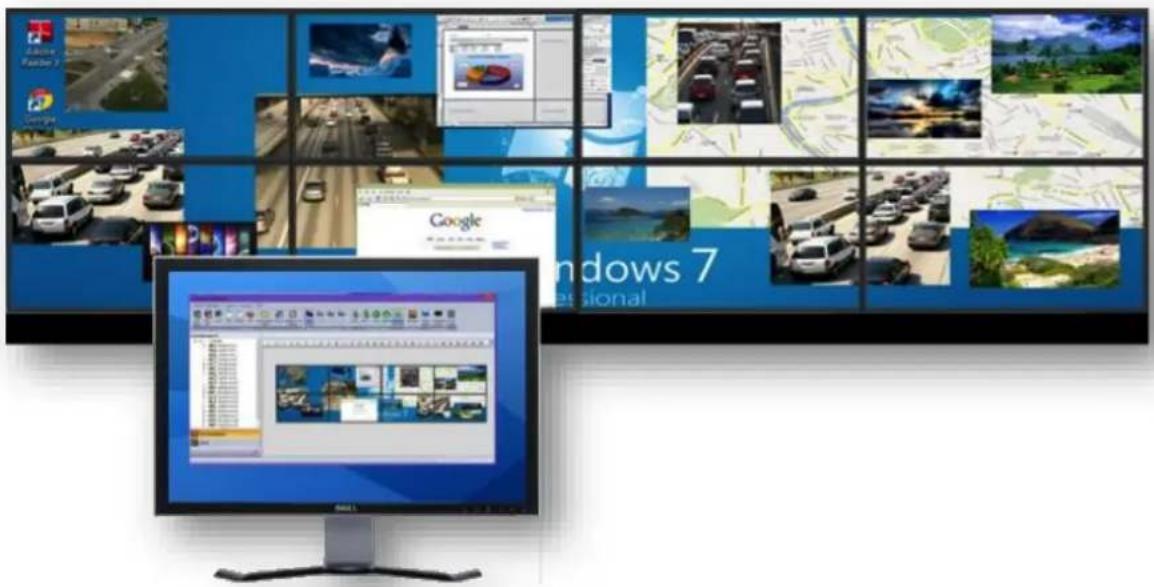
Screenshot of Windows 7 desktop showing multiple video content thumbnails and a desktop computer displaying a webpage with text.Note:
Before starting to use this manual, it is recommended to follow the instructions in 'SolarWall Controller Quick Start Guide' to ensure the SW-Control software has been properly installed and the controller has been configured and connected to the control PC.
Contents
0. Overview
1. Toolbar
1.1. Software Operation
1.1.1. Connect
1.1.2. Disconnect
1.1.3. Communication setting
1.1.4. Configuration
1.1.5. Quit
1.2. Basic Operation
1.2.1. Setting
1.2.2. Multi Screen Wall Operation
1.2.3. Layout File Backup
1.2.4. Preview
1.2.5. Screen Control
1.3. Tools
1.3.1. Management
1.3.2. Layout File Backup
1.3.3. Language
1.3.4. Version
2. Application Toolbar
2.1. Signal Management
2.1.1. Open a window
2.1.2. Cropping
2.1.3. On Screen Display (OSD)
2.1.4. Change the display name of input source
2.1.5. Change EDID on video capture cards
2.2. Layout
2.2.1. Open a layout
2.2.2. Save a layout
2.2.3. Modify a layout
2.2.4. Delete a layout
2.3. Camera List
2.3.1. Set up the IP input signals
2.3.2. Set up the IP Decoder Cards
3. Video Wall Display Area
3.1. Resize a window
3.2. Restore a window
3.3. Move a window
3.4. Full Screen
3.5. Pre-set layout shortcut bar
4. Preview Toolbar
4.1. Set up Preview
4.1.1. Set up the connection of preview card
4.1.2. Preview window function
4.2. Change the Preview setting
0. overview
text_image
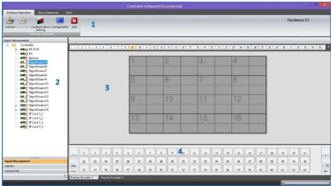
Controller Software[Disconnected] Software Operation Basic Operation Tools Connect Connected Communication Configuration Setting Hardware ID: Signal Management Controller BR DVD PC Iphone SignalSource1 SignalSource8 SignalSource7 SignalSource6 SignalSource5 SignalSource10 SignalSource11 SignalSource12 SignalSource13 SignalSource14 SignalSource15 SignalSource16 IP Card 1_1 IP Card 1_2 IP Card 1_3 IP Card 1_4 1 2 3 4 5 6 7 8 9 10 11 12 13 14 15 16 17 18 19 20 21 22 23 24 25 26 27 28 29 30 31 32 33 34 35 1 2 3 4 5 6 7 8 9 10 11 12 13 14 15 16 1 2 3 4 5 6 7 8 9 10 11 12 13 14 15 16 17 38 19 20 21 22 23 24 25 26 27 28 29 30 31 32 33 34 35 36 37 38 39 40 41 42 play: 43 44 45 46 47 48 49 50 51 52 53 54 55 56 57 58 59 60 61 62 63 Preview Encoder 1 Preview Encoder 2SW-Control is a program that is used to control the SolarWall 2000 & 4000 video wall controllers. It provides a GUI in ribbon style for the users and enable users to interactively move, resize, position and crop any input capture windows. The whole GUI consists of four main parts:
- Toolbar
- Application Toolbar
- Video Wall Display Area
- Preview Toolbar
SW-Control enables users to create and save video wall layouts and load them whenever needed. Moreover, it also allows users to create a layout looping schedule to automatically switch between different layouts.
- Friendly user interface
• RS232 and Telnet
• Multi language support (English, Korean, Russian, Simplified Chinese, traditional Chinese) - Create, copy, save and delete layouts
- Import or export layouts
- Short cuts for each layout
- Looping ability between layouts
• Text overlay on any input source - Position, re-size and crop input windows
- Input signal preview
• Support Windows2000/XP/Vista/7/8.
- User authority management
- Drag and drop easy operation
• Multi video walls control (up to 4 video wall controlling simultaneously)
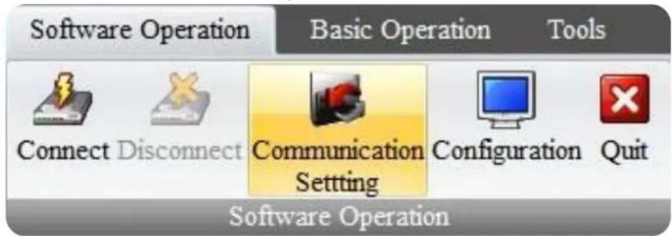
1. Toolbar
The ribbon style tool bar has three groups of tools: software Operation, Basic Operation and Tools.

text_image
Controller Software[Disconnected] Software Operation Basic Operation Tools Connect Designant Communication Configuration Quit Setting Software Operation Hardware ID: Signal Management Controller BR-DVD PC Iphone SignalSource5 SignalSource6 SignalSource7 SignalSource8 SignalSource9 SignalSource10 SignalSource11 SignalSource12 SignalSource13 SignalSource14 SignalSource15 SignalSource16 IP Card 1_1 IP Card 1_2 IP Card 1_3 IP Card 1_4 1 2 3 4 5 6 7 8 9 10 11 12 13 14 15 16 17 18 19 20 21 22 23 24 25 26 27 28 29 30 31 32 33 34 35 36 37 38 39 40 41 42 1 2 3 4 5 6 7 8 9 10 11 12 13 14 15 16 Signal Management Layout Camera List 1 2 3 4 5 6 7 8 9 10 11 12 13 14 15 16 17 18 19 20 21 22 23 24 25 26 27 28 29 30 31 32 33 34 35 36 37 38 39 40 41 42 play . Preview Encoder 1 Preview Encoder 21.1. Software Operation
All the tools in this module are used to set up the controller before use.
text_image
Software Operation Basic Operation Tools Connect Disconnect Communication Setting Configuration Quit Software Operation1.1.1. Connect
Press the Connect button to connect the controller with the control PC after the communication setting has been set up in 2.1.3
Please ensure the controller is fully on before trying to connect with the control PC. A beep sound from the controller a few seconds after it having been switched on indicates the controller is ready for connection.
1.1.2. Disconnect
The Disconnect button will be active if a controller is connected to the control PC. By clicking the Disconnect button, the controller will be able to work standalone without interference from control PC.
1.1.3. Communication setting
This section is used to set up the communication protocol between Control PC and SEADA Video Wall Controller.

text_image
Communication Setting Controller Communication Setting ● NET Connection Device IP 192.168.1.65 Port 1024 COM COM1 BaudRate 9600 Network Check _Config IP Subnet Mask MAC Search Select Advance >> OK CancelTwo connection modes are available for setting up the communication.
1) COM Connection
Choose COM Connection to enable RS232 serial port connection between Control PC and Video Wall Controller
- BaudRate:9600
2) NET Connection
Choose NET Connection to enable the Control PC to control the Video Wall Controller through the network
- The Video Wall Controller's default static IP address is 192.168.1.65
- Port: 1024
- Once the connection setting having been done, click OK to save the change and exit.
For COM connection, no further setting is needed.
For NET connection, a change to the IP address of the Control PC is needed

text_image
Ethernet Properties Networking Sharing Connect using: Realtek PCIe GBE Family Controller Configure... This connection uses the following items: ✓ QoS Packet Scheduler □ Microsoft Network Adapter Multiplexor Protocol ✓ Microsoft LLDP Protocol Driver ✓ Link-Layer Topology Discovery Mapper I/O Driver ✓ Link-Layer Topology Discovery Responder ✓ Internet Protocol Version 6 (TCP/IPv6) ✓ Internet Protocol Version 4 (TCP/IPv4) Install... Uninstall Properties Description Transmission Control Protocol/Internet Protocol. The default wide area network protocol that provides communication across diverse interconnected networks. OK Cancel
text_image
Internet Protocol Version 4 (TCP/IPv4) Properties General You can get IP settings assigned automatically if your network supports this capability. Otherwise, you need to ask your network administrator for the appropriate IP settings. Obtain an IP address automatically Use the following IP address: IP address: 192 . 168 . 1 . 66 Subnet mask: 255 . 255 . 255 . 0 Default gateway: 192 . 168 . 1 . 1 Obtain DNS server address automatically Use the following DNS server addresses: Preferred DNS server: . . . Alternate DNS server: . . . Validate settings upon exit Advanced... OK Cancel- Open the 'Ethernet Properties' windows on the Control PC
- Highlight the TCP/IPv4 in Networking and click the Properties button to open the TCP/IPv4 Properties window
- Change the 'Obtain an IP address automatically' to 'Use the following IP address to set up a static IP address
IP address: any address between 192.168.1.1 and 192.168.1.255 except the address which has been taken by the Video Wall Controller
Subnet mask: 255.255.255.0
Default Gateway: 192.168.1.1. Click Connect button (1.1.1.) to link the Video Wall Controller and Control PC together.
1.1.4. Configuration
text_image
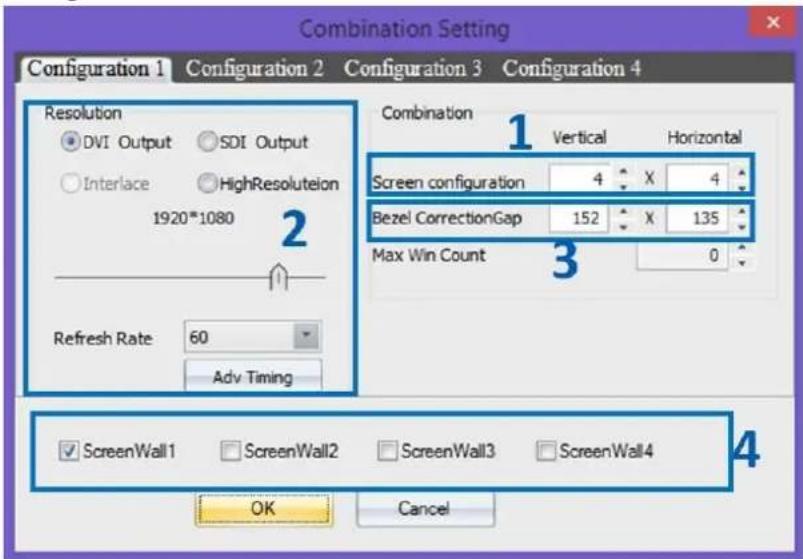
Combination Setting Configuration 1 Configuration 2 Configuration 3 Configuration 4 Resolution DVI Output SDI Output Interlace HighResolution 1920*1080 Refresh Rate 60 Adv Timing Combination 1 Vertical Horizontal Screen configuration 4 X 4 Bezel CorrectionGap 152 X 135 Max Win Count 3 0 ✓ ScreenWall1 ✓ ScreenWall2 ✓ ScreenWall3 ✓ ScreenWall4 OK CancelIn Configuration the following setting can be changed for setting up the video wall displays
1) Screen configuration
The number of screens and the layout of the screens for the video wall can be set up here
2) Screen resolution
The signal format, resolution and frame rate can be set up in this section.
3) Screen bezel correction
In this section, screen bezel can be compensated to obtain accurate display of the image.
Bezel compensation calculation:
Unit: pixel, and assume the parameter as follow
Monitor Bezel width: left = a, right = b
Monitor Bezel width: top = c, bottom = d
Monitor dimension (exclude bezel) = L x H
Monitor resolution = x * y pixel (e.g. 1920 x 1080)
Vertical = +bl * x
Horizontal = +dH * y
4) Multi video walls setting
SEADA SolarWall video wall controllers are able to control up to four video walls independently within one system. Simply tick the number of video walls the system needs to control and then set up the video wall individually in each Configuration.
1.1.5. Quit
Use Quit button to exit the software
1.2. Basic Operation

text_image
New Open Bottom InputOutput Card Close All Top Group Lock Test Background Picture Setting Multi Screen Wall Operation Layout File Backup Preview Open Save Loop Refresh Shortcut Preview Open Shutdown Screen Screen ControlsAll the tools in this module are used to create and manipulate the windows of inputs source on video walls. It consists of five groups of tools as following:
1.2.1. Setting
1) New Open
Click the New Open button to open a window for the highlighted input source onto the video wall.
The system will automatically fit the new open window onto one of the displays on video wall.
Two other ways are able to open a new window of input source onto video wall as well by drag & drop and drawing in Application Toolbar and Video Wall Display Area respectively.
2) Close All
Clicking the Close All button will close all the existing windows on the video wall.
3) Lock
Clicking the Lock button will lock the current highlighted window in Video Wall Display Area for any change
4) Bottom
Clicking the Bottom button will send the current highlighted window to back of other windows in Video Wall Display Area
5) Top
Clicking the Top button will send the current highlighted window in front of other windows in Video Wall Display Area.
6) Test
This tool provides the ability to test the uniformity of brightness and contrast of the displays across the video wall. The left column and the right column enable user to choose different colour and pattern for test respectively.

text_image
Test Window Color Grid OK CancelClicking the Input/Output Card button will open the windows showing the configuration of inputs and outputs cards in the system.

text_image
Input-Output Panel 1 2 3 4 5 6 7 8 9 10 11 12 13 14 15 16 17 18 DLink DLink Input Output << >>8) Group
This function offers the chance to have correct channel mapping between outputs of controller and displays of video walls even when the physical channel mapping is incorrect. It offers up to 4 groups of settings. Each group responses to one video wall independently in multi video wall.
e.g. if the output 1&2 of controller accidentally connect to display 2&1 of video wall, instead of going through rewiring, the correction can be simply done in Group by remapping the channel. In this case map the output 2 to 1 and output1 to 2.

text_image
Screen Group Setting Group1 Group2 Group3 Group4 Output Card List Output 5 Output 6 Output 7 Output 8 Output 9 Output 10 Output 11 Output 12 Output 13 Output 14 Output 15 Output 16 Output 17 Output 18 Output 19 Output 20 Output 21 Output 22 Output 23 Output 24 Output 25 Output 1 Output 2 Output 3 Output 4 Cancel Reset OK9) Background Picture
Users can use this function to load a desktop background image onto the video wall. The image must be .bmp @ 24bit format.

text_image
Background Image Operation Del All Files Select Image OK Cancel Back Picture Enable Screen ID #Picture Name Startin... Startin. ✓ 1 #[1] Photography_wallpapers_350.bmp 0 0 2 #[1] Photography_wallpapers_350.bmp 0 1 3 #[1] Photography_wallpapers_350.bmp 0 1 1 2 3 4 5 6 7 8 9 10 11 12 13 14 15 16Users are able to load new images by clicking Select Image button and press Add button

text_image
Background Image Processing ID File Name Reset Add Apply OK1.2.2. Multi Screen Wall Operation
Once the multi video walls being set up in configuration (1.1.4), the number of video walls will be active here. By clicking from wall1 to wall 4 to control the different video walls using one system.
1.2.3. Layout File Backup
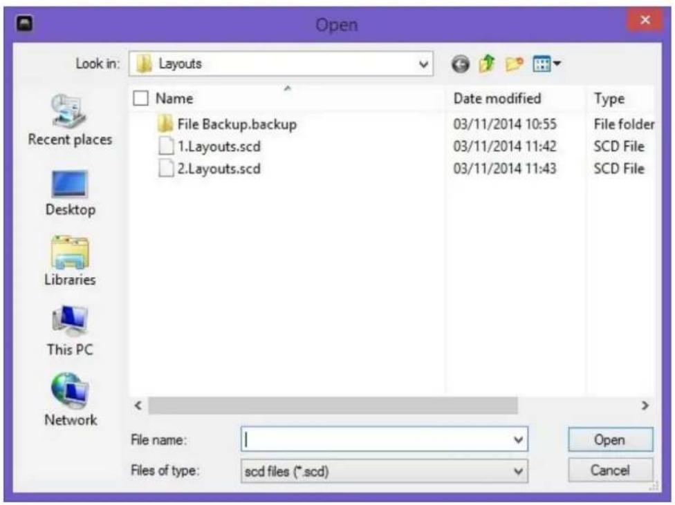
1) Open
It is used to open an existing layout from the control PC. It can also be done using layout in Application Toolbar or shortcut in Video Wall Display Area.
text_image
Open Look in: Layouts Recent places Desktop Libraries This PC Network Name File Backup.backup 1.Layout.scd 2地说s.scd Date modified 03/11/2014 10:55 03/11/2014 11:42 03/11/2014 11:43 Type File folder SCD File SCD File File name: I Files of type: scd files (*.scd) Open Cancel2) Save
It saves a layout with a specific name from user.

text_image
Layout Saving Layout ID 3 Layout Name OK Cancel3) Loop
This offers the function to cycle through the pre-set layouts in a specific time interval automatically allowing users to view each layout in turn.
Click Loop to open Loop setting window to choose the pre-set layouts (Figure?-1) for the input contents looping. The time gap (Figure?-2) and sequence of the layouts (Figure?-3) can be set up in this window as well.

text_image
Loop Setting ID Camera Layout ID Layout Name 1 □ 1 1 L1_background □ 2 2 L2_camera_ful screen □ 3 3 L3_single □ 4 4 L4_Crop □ 5 5 L5_BR_DVD □ 6 6 L6_overlay1 □ 7 7 L6_BR_DVD_single □ 8 8 L8_Camera1_single □ 9 9 L9 □ 10 10 10 Adjust Sequence 3 Loop interval 2 UP Select All 0 Minute Down Select None 5 Second OK Stop4) Refresh
Refresh the looping
5) Shortcut
To show or hide layout shortcut at the top of Video Wall Display Area.
1.2.4. Preview
To show or hide Preview Toolbar shortcut at the bottom of Video Wall Display Area.
Note: In order to make Preview function work, a preview output card (P/N: SW-Preview) is needed for the system.
1.2.5. Screen Control
The tools of this section offer users the ability to remote turn on /off the displays of video walls. SEADA has been working with our display supply partners to embed their products in our system. However it is not possible to include all the models of displays on market. So if users would like to use function, please contact our sales for further information.
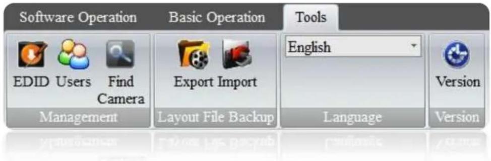
1.3. Tools
text_image
Software Operation Basic Operation Tools EDID Users Find Camera Export Import English Management Layout File Backup Language Version Language1.3.1. Management
1) EDID
Press this button will open EDID Editer which enables user to create custom EDID file for updating video capture cards.
It is recommended to create a new EDID file from an existing EDID file.

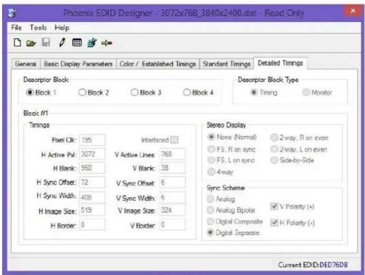
text_image
File Tools Help Open Look in: edd Name Date modified 1080p@35.dat 17/07/2014 10:41 1080p@60.dat 17/07/2014 10:41 1200p@60.dat 19/01/2015 12:25 2560x1600_3840x2400.dat 05/08/2010 05:35 3072x768_3840x2400.dat 05/08/2010 05:25 File name: Fles of type: EDID DAT file (*.dat) Open Cancel Current EDID:NoneEnsure the Designer is on modify mode by clicking the 📄 in tool bar. Users can change the H Active Pxl and V Active Lines in Block 1 of Detailed Timings to set up new resolution for EDID
text_image
Phoenix EDID Designer - 3072x768_3840x2400.dat - Read Only File Tools Help General Basic Display Parameters Color / Established Timings Standard Timings Detailed Timings Descriptor Block ● Block 1 ○ Block 2 ○ Block 3 ○ Block 4 Block #1 Timings Pixel Clk: 195 Interaced H Active Px: 3072 V Active Lines: 768 H Blank: 960 V Blank: 38 H Sync Offset: 72 V Sync Offset: 6 H Sync Width: 408 V Sync Width: 6 H Image Size: 519 V Image Size: 324 H Border: 0 V Border: 0 Stereo Display ● None (Normal) ○ 2-way, R on even ○ F5, R on sync ○ 2-way, L on even ○ F5, L on sync ○ Side-by-Side ○ 4-way Sync Scheme ○ Analog ○ Analog Bipolar √ V Polarity (+) ○ Digital Composite √ H Polarity (+) ● Digital Separate Current EDID:DED76DB2) Users
User authority can be managed here. Three different levels of access authority can be set up here.
- Admin level
- Advanced Users
- Users

text_image
User Management-ADMIN User List User Name Type Screen Wall ID ADMIN Admin ALL User Users -- User Management User ADMIN Password Re password User Type Admin Administr Advanced Users Users Add Edit Del OK Cancel Apply3) Find Camera
This function allows users to find all the IP cameras connected to the system.

text_image
Find Network Camera ID Name GUID 1 ip1 rtsp://admin:@192.168.1.60/live1.sdp1.3.2. Layout File Backup
1) Export
This function enables users to export all the pre-set layouts for future reference.
2) Import
This function enables users to import the pre-set layout file from previous control PC.
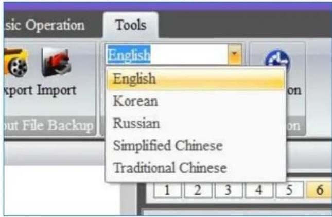
1.3.3. Language
Use the drop down list to select the preferred language rather than English
text_image
Music Operation Tools English English Korean Russian Simplified Chinese Traditional Chinese1.3.4. Version
It shows the version information for the control software and firmware of the cards in the system.

text_image
Software Version Information <2. Application Toolbar

text_image
Controller Software[Disconnected] Software Operation Basic Operation Tools Connect Discount Communication Configuration Setting Hardware ID : Software Operation Connect Discount Communication Configuration Setting Software Management Controller IP-DVD PC iphone SignalSource1 SignalSource6 SignalSource7 SignalSource8 SignalSource9 SignalSource10 SignalSource11 SignalSource12 SignalSource13 SignalSource14 SignalSource15 SignalSource16 IP Card 1_1 IP Card 1_2 IP Card 1_3 IP Card 1_4 1 2 3 4 5 6 7 8 9 10 11 12 13 14 15 16 17 18 19 20 21 22 23 24 25 26 27 28 29 30 31 32 33 34 35 1 2 3 4 5 6 7 8 9 10 11 12 13 14 15 16 17 18 19 20 21 5 6 7 8 9 10 11 12 13 14 15 16 Special Management Layout Source List Preview Encoder 1 Preview Encoder 22.1. Signal Management
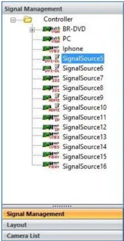
The Signal Management window displays a list of input content windows that can be displayed onto the video wall. The system will automatically identify the type of source and display it under the PCB Icon for each input
text_image
Signal Management Controller BR-DVD PC Iphone SignalSource5 SignalSource6 SignalSource7 SignalSource8 SignalSource9 SignalSource10 SignalSource11 SignalSource12 SignalSource13 SignalSource14 SignalSource15 SignalSource16 Signal Management Layout Camera List2.1.1. Open a window
Use the mouse to select the required input and then drag & drop to a preferred position on the Video Wall Display Area. The system will automatically fit the new open window onto one of the displays on video wall.
Or select the required input and then click the New Open button in Basic Operation module on Toolbar.
Or select the required input and then draw a window on the Video Wall Display Area.
2.1.2. Cropping
This function allows user to display a specific area of the input signal content onto the video walls.
1) Highlight the input signal and right click to open the drop down menu
2) Choose Add Mode in the list to open the cropping window

text_image
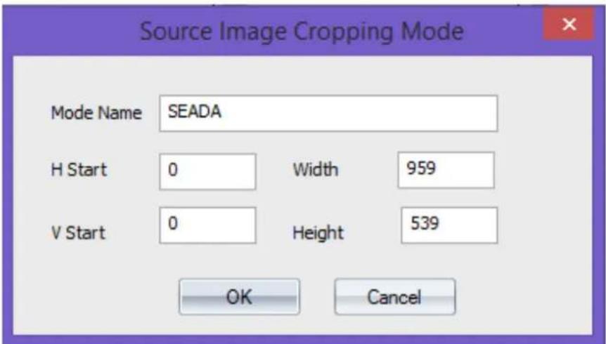
SDI SignalSource8 HDMI SignalSource HDMI SignalSo IP SignalSo IP SignalSo DVI-DL SignalSo DVI-DL SignalSo 4CVBS SignalSo 4CVBS SignalSource10 Input Signal Group Switch OSD Update EDID Modify Name Add Mode3) In cropping window, there are five parameters for users to define the cropped window
text_image
Source Image Cropping Mode Mode Name SEADA H Start 0 Width 959 V Start 0 Height 539 OK Cancela. Mode Name: ensure unique name for each cropped window
b. H Start: Pixel location of start point for horizontal axis
c. V Start: Pixel location of start point for vertical axis
d. Width: the width of cropped window (unit: Pixel)
e. Height: the height of cropped window (unit: Pixel)
4) Once the parameters having been set up, press OK to create the cropped window
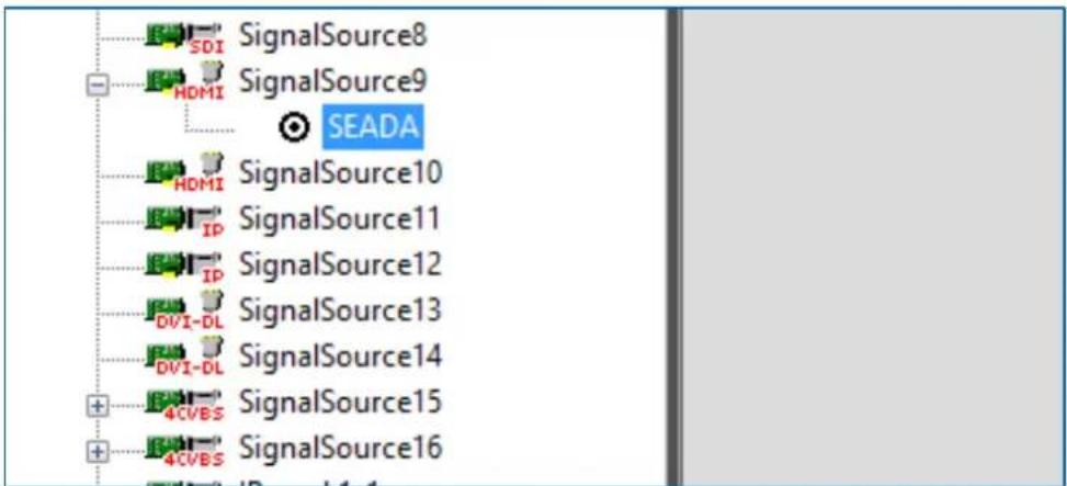
5) The created cropped windows will be displayed under the parent window
text_image
SDI SignalSource8 HDMI SignalSource9 SEADA HDMI SignalSource10 IP SignalSource11 IP SignalSource12 DVI-DL SignalSource13 DVI-DL SignalSource14 4CVBS SignalSource15 4CVBS SignalSource162.1.3. On Screen Display (OSD)
This function will enable users to display an on screen dialogue for each window on video wall.
1) Right click the input window in Signal Management and then choose OSD in drop down menu to open the Screen OSD Information window.

text_image
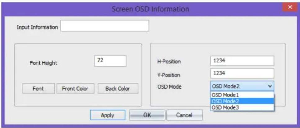
SDI SignalSource8 HDMI SignalSo Input Signal Group Switch HDMI SignalSo OSD SignalSo Update EDID IP SignalSo Modify Name DVI-DL SignalSo Add Mode DVI-DL SignalSo 4CVBS SignalSo 4CVBS SignalSource102) In Screen OSD Information, users are able to create the OSD in specific format
a. Input Information: Enter the message here for OSD text
b. Font Height: Size of the OSD text
c. Font: Determine the characteristics of the font for OSD text
d. Front Color: Colour of the Text
e. Back Color: OSD text background colour
f. H-Position: Define the horizontal position of OSD (unit: pixel)
g. V-Position: Define the Vertical position of OSD (unit: pixel)
h. OSD Mode:
I. OSD Mode1 No OSD shown on screen
II. OSD Mode2 OSD without background
III. OSD Mode3 OSD with background
text_image
Screen OSD Information Input Information Font Height 72 H-Position 1234 V-Position 1234 OSD Mode OSD Mode2 OSD Mode1 OSD Mode2 OSD Mode3 Font Front Color Back Color Apply OK Cancel2.1.4. Change the display name of input source
This function will enable users to customize the input signal window name in signal management window.
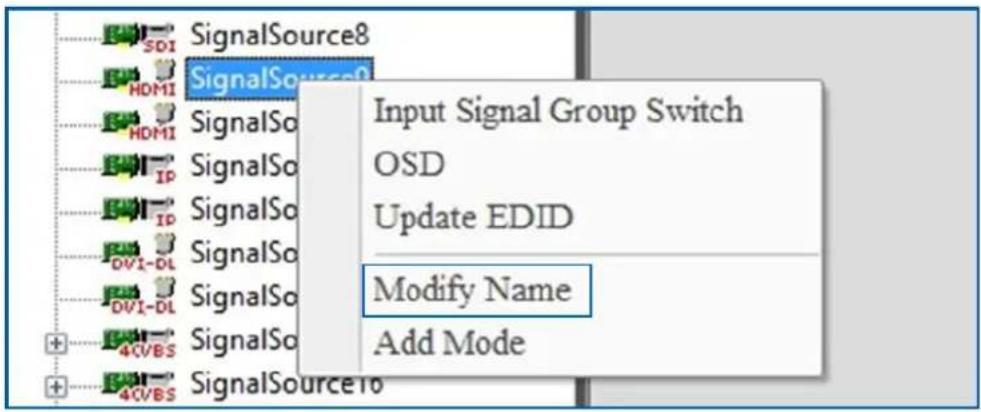
1) Right click the input window in Signal Management and then choose Modify Name in drop down menu to open the Modify Signal Name window.
text_image
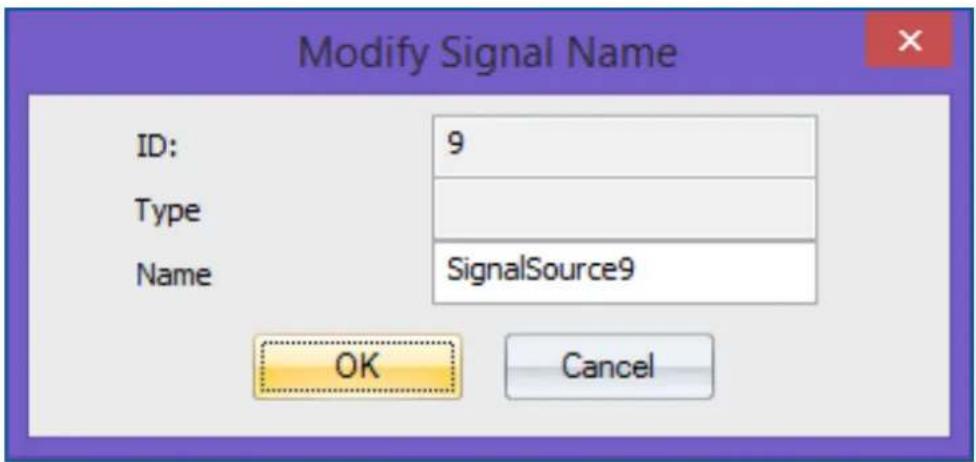
SignalSource8 SignalSource0 Input Signal Group Switch OSD Update EDID Modify Name Add Mode2) The default name for each input signal is 'SignalSource' with unique number. The users are able to re-define the name of each input signal for future reference
text_image
Modify Signal Name ID: 9 Type Name SignalSource9 OK Cancel2.1.5. Change EDID on video capture cards
This feature allows users to update the EDID on input cards to a pre-set EDID to obtain a specific resolution and ratio input signal.
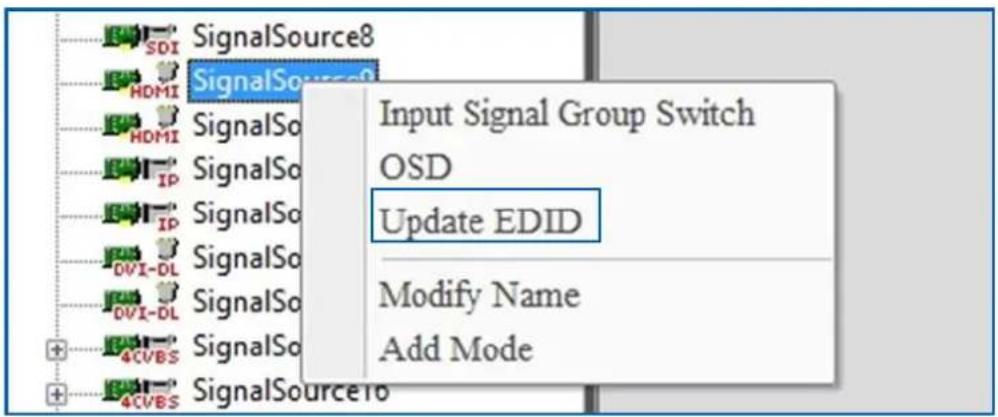
1) Right click the input window in Signal Management and then choose Update EDID in drop down menu to open the window showing the list of available EDID setting in system.
text_image
SDI SignalSource8 HDMI SignalSource HDMI SignalSo Input Signal Group Switch IP SignalSo OSD IP SignalSo Update EDID 0V1-DL SignalSo Modify Name 0V1-DL SignalSo Add Mode 4CVBS SignalSo 4CVBS SignalSource2) All the pre-set EDID will be displayed in the windows. Customized EDID is able to be obtained by using Phoenix EDID Designer in Tools (1.3.1)

text_image
Open Look in: edid Recent places Desktop Libraries This PC Network Name Date modified Type 1080p@35.dat 17/07/2014 10:41 DAT File 1080p@60.dat 17/07/2014 10:41 DAT File 1200p@60.dat 19/01/2015 12:25 DAT File 2560x1600_3840x2400.dat 05/08/2010 05:35 DAT File 3072x768_3840x2400.dat 05/08/2010 05:25 DAT File File name: I Open Files of type: Edid Files (*.DAT) Cancel3) Open the EDID file to update the EDID of the video capture channel. A dialog window will be shown to indicate that the EDID update is succeeded.
4) Unplug and plug the signal cable to enable the capture source read the new EDID.
2.2. Layout
In layout, it lists all the pre-set layouts of the video walls for users to manipulate from.

text_image
Layout ID Layout Name 1 Layout1 2 Layout2 3 SEADA Logo full screen 4 IP camera centre 5 Open 6 Save 7 Modify 8 Delete 9 102.2.1. Open a layout
There are two ways to open a pre-set layout in Layout
1) Use mouse to double click the layout using mouse left button
2) Right click the mouse onto the layout and choose Open in drop down menu
2.2.2. Save a layout
This allows user to save a modified layout over an existing layout or save it as new layout. Right click the mouse onto the layout and choose Save in drop down menu.
2.2.3. Modify a layout
This feature allows users to modify the name of existing layouts only
2.2.4. Delete a layout
This feature allows users to delete the existing layouts
2.3. Camera List
In this section users are able to set up the entire IP input source for system to decode and capture RTSP IP signals. SEADA IP-IN-IP8 IP decoder card is able to decode & capture up to 8 channels of 1080P or 16 channels of 720p or 36 channels of D1 IP sources.
text_image
Camera List Find Refresh Camera List IP camera 2 Signal Management Layout Camera List2.3.1. Set up the IP input signals
Before going any further, ensure the RTSP address of the IP signal has been obtained either through IP camera manual or suppliers.
For example: D-Link-2230 has the RTSP address of rtsp://x.x.x.x/live1.sdp where the x.x.x.x represents the IP address of the camera. Therefore the RTSP address for SolarWall video wall controller is rtsp://a:b@x.x.x.x/video1.sdp where a represents username and b represents password for the camera. If there is no password, please leave b empty.
Note: if the rtsp address for SolarWall system does not include username and password, the system will ask for username and password every time when the IP camera being used.
1) Using the software coming with the device to set up the IP address of each device to match the IP group of SolarWall Controllers (the default IP address for SW controller is: 192.168.1.65). Ensure each input has a unique IP address in the system.
2) Use free download software of VLC media player to test the RTSP address of devices to ensure the RTSP address is valid. Ensure the cameras connect to control PC and IP cards at the same time through Ethernet switch, not connect to IP cards port directly.
Assume the IP address of D-Link-2230 is 192.168.1.60 and the username is admin without password, the RTSP address for this IP camera is
rtsp://admin:@192.168.1.60/live1.sdp
The below setting will open the IP streaming from this D-Link-2230 IP camera
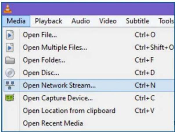
text_image
Media Playback Audio Video Subtitle Tools Open File... Ctrl+O Open Multiple Files... Ctrl+Shift+O Open Folder... Ctrl+F Open Disc... Ctrl+D Open Network Stream... Ctrl+N Open Capture Device... Ctrl+C Open Location from clipboard Ctrl+V Open Recent Media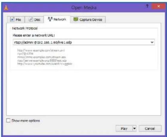
text_image
Open Media File Disc Network Capture Device Network Protocol Please enter a network URL: rtsp:/admin: @192.168.1.60/live 1.sdp http://www.example.com/stream.avi rpsf@1374 mmsy/mmw.example.com/retam.sdp rtsp:/www.example.org/8000/test.sdp http://www.youltie.com/watch?v-gg4o Show more options Play Cancel3) Right click the Camera List and choose Add Camera to open a Camera URL Property dialog window.

text_image
Camera List Find Refresh Camera List Add Camera4) In Camera URL Property dialog window, user defines the unique name for each camera in Camera Name and enter the RTSP address for the camera

text_image
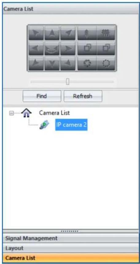
Camera URL Property Camera ID: 2 0 Camera Name: IP camera 2 Camera URL: rtsp://admin:@192.168.1.60/live1.sdp Access Mode IP Name Port Password OK Cancel5) Click OK to add the IP camera into the list. Do the same procedure for the other IP source to add them into the camera list

text_image
Find Refresh Camera List IP camera 2 Signal Management Layout Camera List2.3.2. Set up the IP Decoder Cards
1) After all the IP cameras having been added into Camera List, users need to go to Signal Management window to link the IP camera with IP capture channel accordingly.
a. SEADA Technology IP decoder card has two physical RJ45 connectors and each connect shows two inputs channels in Signal Management window. Each channel is able to decode & capture up to 2 1080P or 4 720P or 9 D1 IP sources
2) Right click on the SignalSource where the IP camera is connected to and choose Decode Property to open Network Decoder Property dialog window.

text_image
Network Decoder Property : URL0: rtsp://admin:@192.168.1.60/live1.sdp URL1: rtsp://admin:@192.168.1.60/live1.sdp URL2: rtsp://admin:@192.168.1.60/live1.sdp URL3: rtsp://admin:@192.168.1.60/live1.sdp URL4: rtsp://admin:@192.168.1.60/live1.sdp URL5: rtsp://admin:@192.168.1.60/live1.sdp URL6: rtsp://admin:@192.168.1.60/live1.sdp URL7: rtsp://admin:@192.168.1.60/live1.sdp URL8: rtsp://admin:@192.168.1.60/live1.sdp ID URL Adv<< OK Apply Cancel IP: 192.168.1.11 SubnetMask: 255.255.255.0 Gateway: 192.168.1.254 MAC: 10:0C:29:98:D6:04 Version: Modify IP Decoder Mode 1 Mode Modify Mode3) Click Adv<< button to set up the IP address for each IP decoder card to match the IP group of IP cameras. (e.g. IP address of camera is 192.168.1.60)
a. IP: 192.168.1.x x represents a number between 1 and 255 which has not been used by any other device in the system
b. SubnetMask: 255.255.255.0
c. GateWay: 192.168.1.1
d. MAC: obtain automatically
Please note: each SEADA IP decode card needs two unique IP addresses and one for each physical RJ45 connector respectively.
After having entered the IP address for each card, press Modify IP button to change the IP address.
4) Choose the Decode Mode
1 Mode each channel capture 1 IP source up to 1080p
2 Mode each channel capture 2 IP source up to 1080p
4 Mode each channel capture 4 IP source up to 720p
9 Mode each channel capture 9 IP source up to D1
- Users are able to choose the decode mode in Adv<< of Network Decoder Property
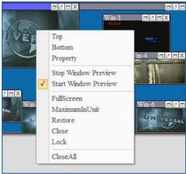
- Or users are also able to choose the decode mode by right clicking the IP window in Video Wall Display Area to choose the mode in IP Decoder Mode in drop down menu Right click the IP window in Video Wall Display Area to choose the mode in IP Decoder Mode in drop down menu
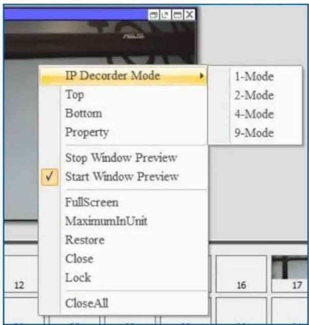
text_image
IP Decorder Mode Top Bottom Property Stop Window Preview Start Window Preview √ Fullscreen MaximumInUnit Restore Close Lock CloseAll 1-Mode 2-Mode 4-Mode 9-Mode 16 175) Once the IP address and decode mode has been set, the IP decoder card is ready to be linked to IP cameras accordingly. There are two ways to link them together a. Drag and drop
- Open one IP window from Signal Management to Video Wall Display Area. It will be a black window since there is no IP camera input on this channel.

text_image
Win-0II. And then go to camera list to drag the IP camera and drop into the window to form a link.
b. Enter rtsp address
Enter the rtsp address of IP cameras in Network Decoder Property accordingly
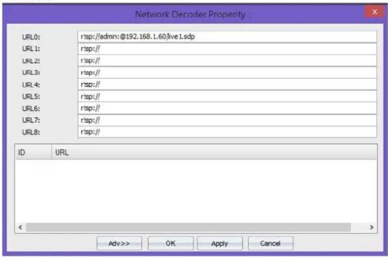
text_image
Network Decoder Property : URL0: rtsp://admin:@192.168.1.60/live 1.sdp URL1: rtsp:// URL2: rtsp:// URL3: rtsp:// URL4: rtsp:// URL5: rtsp:// URL6: rtsp:// URL7: rtsp:// URL8: rtsp:// ID URL < Adv >> OK Apply Cancel3. Video Wall Display Area
In Video Wall Display Area, users are able to manipulate the windows on video walls.
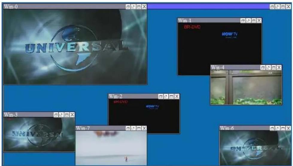
text_image
Win-0 UNIVERSAL Win-1 BR-DVD HOW TV Win-4 Win-3 BR-DVD HOW TV Win-7 Win-63.1. Resize a window
1) Use the mouse to highlight the window and move the mouse to the border of the window. The cursor will be changed to a resize cursor.
2) Press and hold the left mouse button and drag the border to resize the window to required size
3) Click the fit in button on title bar to automatically resize the window to fit the grid area (each window is divided into 4 even grids) where the window was in.
1) Either click the Restore button on the title bar to restore the window
2) Or right click the window and then choose restore in the drop down menu

text_image
Top Bottom Property Stop Window Preview Start Window Preview Fullscreen MaximumInUnit Restore Close Lock CloseAll3.3. Move a window
1) Use the mouse to highlight the window and position the cursor on the window
2) Press and hold the left mouse button and drag the window to the required position, and release the mouse button
3.4. Full Screen
1) Either click the Full Screen button on the title bar
2) Or right click the window and then choose FullScreen in the drop down menu
text_image
Top Bottom Property Stop Window Preview Start Window Preview Fullscreen MaximumInUnit Restore Close Lock CloseAll3.5. Pre-set layout shortcut bar
This is the shortcut of layout in application ToolBar. It shows the first 40 pre-set layouts having been saved by users. The numbers in the bar are the ID of each pre-set layout. Left click each number will load the layout under that ID number.

text_image
1 2 3 4 5 6 7 8 9 10 11 12 13 14 15 16 17 18 19 20 21 22 23 24 25 26 27 28 29 30 31 32 33 34 35 36 37 38 39 40 1 2 3 44. Preview Toolbar
Preview Toolbar is able to display up to 128 input signal preview windows to enable users to check the input source before putting them onto the video wall by using a preview card (SW-Preview). The preview card is also able to capture the video wall screen and display it on SW-Control software

text_image
1 2 3 4 5 6 7 8 9 10 11 12 13 14 15 16 17 18 19 20 21 22 23 24 25 26 27 28 29 30 31 32 33 34 35 36 37 Win-0 WINSAL 1 2 3 4 5 6 7 8 9 10 11 12 13 14 15 16 17 18 19 20 21 22 23 24 25 26 27 28 29 30 31 32 33 34 35 36 37 Preview Encoder 1 Preview Encoder 24.1. Set up Preview
4.1.1. Set up the connection of preview card
A preview card is connected and managed by control PC via IP. The default IP address for preview card is 192.168.1.85. Ensure the IP address does not conflict with other IP addresses in the same system.
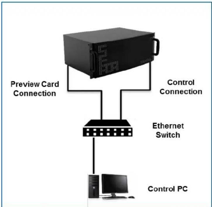
flowchart
graph TD
    A["Server"] -->|Preview Card Connection| B["Ethernet Switch"]
    A -->|Control Connection| B
    B --> C["Control PC"]
    style A fill:#000,stroke:#fff,color:#fff
    style B fill:#000,stroke:#fff,color:#fff
    style C fill:#000,stroke:#fff,color:#fff
Connect the SW-Control software with the controller through Ethernet Switch and then press Play button at the left corner to get all the preview images of all input signals.

text_image
Preview Encoder 1 Preview Encoder 24.1.2. Preview window function
1) Double click each preview window to open a larger single window to enable users to observe more detail
2) Users are able to drag and drop to open the windows in Video Wall Display Area from Preview window
4.2. Change the Preview setting
Press the set button at the bottom of right corner to open the setting dialog window. Users are able to change the IP setting and the resolution of the preview image.
Please be noted that the set is only available when the preview is on stop.
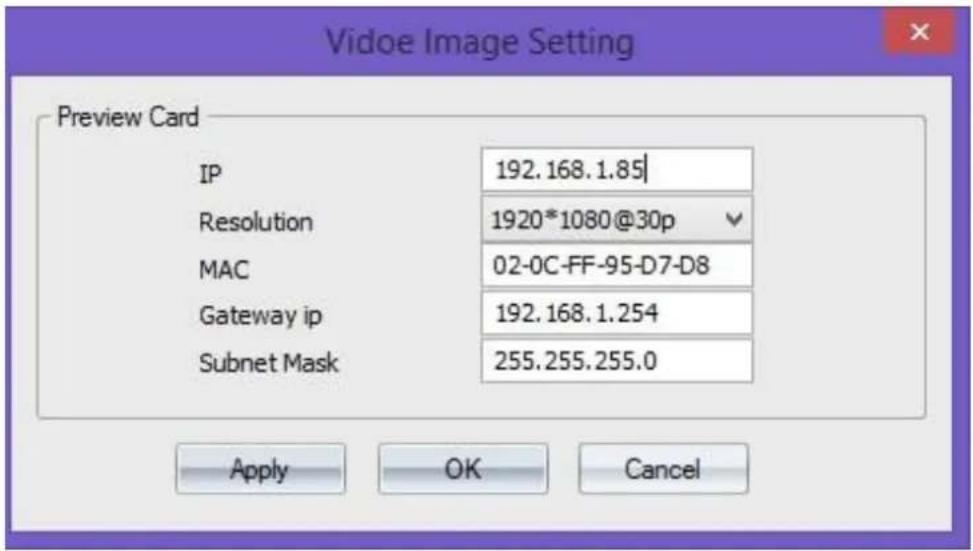
text_image
Vidoe Image Setting Preview Card IP 192.168.1.85| Resolution 1920*1080@30p MAC 02-0C-FF-95-D7-D8 Gateway ip 192.168.1.254 Subnet Mask 255.255.255.0 Apply OK CancelSEADA Technology Ltd
Oak Tree Park
Burnt Meadow Road
Moons Moat North Industrial Estate
Redditch
Worcestershire
B98 9NW
United Kingdom
Email: sales@seada.co.uk
Phone: +44 (0)1527 584364
Fax: +44 (0)1527 962998
