LGHOBX16 - Cooker Logik - Free user manual and instructions
Find the device manual for free LGHOBX16 Logik in PDF.

User questions about LGHOBX16 Logik
0 question about this device. Answer the ones you know or ask your own.
Ask a new question about this device
Download the instructions for your Cooker in PDF format for free! Find your manual LGHOBX16 - Logik and take your electronic device back in hand. On this page are published all the documents necessary for the use of your device. LGHOBX16 by Logik.
USER MANUAL LGHOBX16 Logik
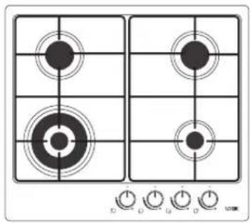
natural_image
Top-down view of a four UK-style gas stove with four flanges and control knobs (no visible text or symbols)
Contents
Safety Warnings....4
Unpacking....6
Product Overview....7
The Main Unit....7
Control Panel....7
Before Using Your New Hob 8
Lighting the Hob 8
Flame Failure Safety Feature 9
If the Burner Does Not Light....9
If the Flame is Irregular 9
Electricity Failure....9
Cookware Guidelines 10
Cleaning and Maintenance....11
Cleaning the Gas Hob 11
Burner Parts and Pan Supports 12
Replacing the Burners....12
Hob Controls 12
Hints and Tips 13
Specifications....14
Table for the Choice of the Injectors 15
Installation....16
Wiring 16
Ventilation Requirements....17
Gas Installation....17
Installation and Service Regulations 17
Location....18
When the Hob is First Installed.... 19
Gas Connection....19
Cut Out Dimensions 20
Product Overall Dimensions....20
Fitting the Hob into the Worktop 20
Fixing Points 20
Attaching the fixing brackets....21
Check the Hob After Installation & Before Using 21
Pressure Testing 21
Conversion from NG to LPG or from LPG to NG....22
Natural Gas....22
LP Gas 22
Method....22
To Adjust the Gas Rate 22
Minimum Setting or Turn Down 23
Burner Configuration 23

Safety Warnings
IMPORTANT SAFETY INSTRUCTIONS READ CAREFULLY AND KEEP FOR FUTURE REFERENCE
- This appliance must be installed by a qualified Gas Safe registered engineer. The manufacturer is not responsible for any damage caused by incorrect installation.
- Check whether there is any damage to the appliance after you have unpacked it. If any damage is found, do not use the appliance and contact the store where you purchased it.
• This appliance is for indoor domestic use only.
- This appliance is for cooking purposes only. It must not be used for other purposes, for example room heating.
- The hob is fitted with a moulded mains plug. The mains plug must remain accessible or a switch providing full disconnection incorporated in the fixed wiring.
- If the mains cable gets damaged, it should be replaced by an authorized service agent or qualified electrician in order to avoid a hazard.
- The hob must be used in a well ventilated location and installed on flat / level surface.
• Only operate your appliance in a dry atmosphere.
- Keep the electrical cables of your other appliances away from hot areas; do not let them touch the appliance.
- Ensure that the appliance is switched off at the mains supply switch and allowed to completely cool down before cleaning or performing any maintenance to avoid the possibility of an electric shock or burns.
- The use of a gas cooking appliance results in the production of heat, moisture and products of combustion in the room in which it is installed. Ensure that the kitchen is well ventilated especially when the appliance is in use. Keep natural ventilation holes open or install a mechanical ventilation device (mechanical extractor hood).
- Prolonged intensive use of the appliance may call for additional ventilation, for example opening of a window, or more effective ventilation, for example increasing the level of mechanical ventilation where present.
- This appliance can be used by children aged from 8 years and above and persons with reduced physical, sensory or mental capabilities or lack of experience and knowledge if they have been given supervision or instruction concerning use of the appliance in a safe way and understand the hazards involved.
- Cleaning and user maintenance shall not be made by children without supervision.
- Children should be supervised to ensure that they do not play with the appliance.
- During use the appliance becomes hot. Care should be taken to avoid touching the hob burners / pan stands.
- The appliance and its accessible parts become hot during use. Young children should be kept away.
- Unattended cooking on a hob with fat or oil can be dangerous and may result in fire. NEVER try to extinguish a fire with water, but switch off the appliance and then cover the flame e.g. with a lid or a fire blanket.
• Danger of fire: Do not store items on the cooking surfaces. - When the hob is hot never touch any parts that get hot. Allow the hob to cool before touching these parts.
- Before starting to use your appliance, keep curtains, tulle, paper or flammable materials away from your appliance.
- Do not keep combustible or flammable things in, on or near the appliance.
- Do not use steam cleaners for cleaning the appliance.
- The appliance is not intended to be operated by means of an external timer or separate remote-control system.
- This appliance is not designed to be used with hob guards. Use of inappropriate hob guards can cause accidents.
Thank you on the purchase of your new Logik 4 Burner Gas Hob.
You must read this manual in order to fully understand how to operate it correctly.
This unit MUST be installed by a competent and registered engineer (Gas Safe in the UK).
Please allow the installer to view the installation section of this manual.
Read all the safety warnings carefully before use and keep this manual for future reference.

Unpacking
Remove all packaging from the unit. Retain the packaging. If you dispose of it please do so according to local regulations.
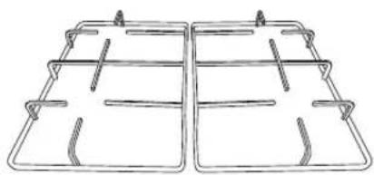
The following items are included:
natural_image
Four identical electric cooktops with circular cutouts on a grid, placed on a white surface with a power switch base (no text or symbols visible)Main Unit
natural_image
Line drawing of two identical rectangular metal trapezoidal compartments with vertical supports (no text or symbols)Pan Support (Left/Right) × 2

Fixing Plate and Screw × 4

130 mm Burner Ring × 1
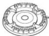
70 mm Burner Ring × 2
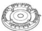
50 mm Burner Ring × 1
130 mm Burner Cap × 1
70 mm Burner Cap × 2
50 mm Burner Cap × 1 Seal × 1
LPG Conversion Kit:

LPG Nozzle × 4
Type of gas
3+ G30/31 28-30/37 mbar
LPG Replacement Rating
Plate Sticker × 1

If items are missing or damaged please contact Partmaster (UK only).
Tel: 0344 800 3456 for assistance.
The Main Unit
text_image
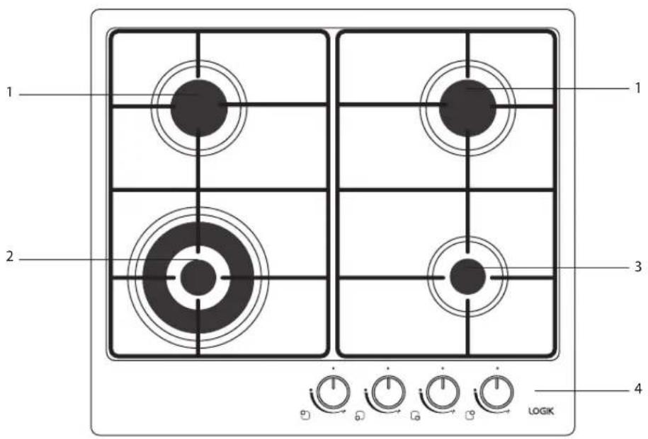
1 2 3 4 LOGIK- Standard Burner (70 mm)
- Large Burner (130 mm)
- Small Burner (50 mm)
- Control Panel
Control Panel
text_image
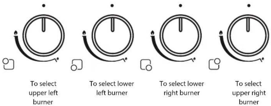
To select upper left burner To select lower left burner To select lower right burner To select upper right burner* All images are for indication only; please refer to your individual unit for actual item.

Before Using Your New Hob
Before using your new hob, please:
- Read this manual fully taking special note of the 'Safety Warnings' section.
- Plug the hob into the electricity supply and turn it on so that the ignition circuit will work.

This appliance is for cooking purposes only. It must not be used for other purposes, e.g. room heating.

Lighting the Hob
- Choose the control for the burner you want to use.
- Press and hold the Burner control in. The spark ignition will operate whilst you hold in the control. While pressing the burner control down, turn it anti-clockwise to the large flame symbol ▶. Continue to hold the control in for approximately 10 seconds after the burner has lit. Releasing the control too soon will extinguish the flame due to the flame failure safety feature.
Manual Ignition (in case of electricity failure)

text_image
Off High LowTo ignite one of the burners, press and turn the control counter-clockwise so that the control is at the position. Hold an ignition source (e.g. candle lighter) close to the upper circumference of the burner. Move the ignition source away as soon as you see a stable flame. Continue holding the control in for approximately 10 seconds after the burner has lit. Releasing the control too soon will extinguish the flame due to the flame failure safety feature.
- Adjust the flame anywhere between the and positions. Do not adjust the flame between the and Off position.
- After ignition, check the flames visually. If you see yellow tipped, lifted or unstable flames; turn the control off. Allow the burners to cool before touching, then check the assembly of the burner rings and caps. Also, make sure that no liquid has entered into the burner cups. If the burner flames go out accidentally, turn the burners off, and do not try to light them again for at least 90 seconds (to allow the gas to disperse).
- When turning the hob off, turn the control in a clockwise direction to the off mark, ' ●'.

- If the burner does not light within 15 seconds, turn the control off and wait for at least 90 seconds before trying again.
• To switch the burner off, turn the control clockwise to the off position.
• After use, always turn the controls to the off position.

- This appliance is for cooking purposes only. It must not be used for other purposes, for example room heating.
- The use of a gas cooking appliance results in the production of heat, moisture and products of combustion in the room in which it is installed. Ensure that the kitchen is well ventilated especially when the appliance is in use: keep natural ventilation holes open or install a mechanical ventilation device (mechanical extractor hood). Prolonged intensive use of the appliance may call for additional ventilation, e.g. opening of a window, or more effective ventilation, e.g. increasing the level of mechanical ventilation where present.

Flame Failure Safety Feature
The flame supervision device (FSD) probe cuts off the gas supply to the burner within one minute if the flame is extinguished. Gas will flow out of the burner until the FSD cools down and activates, so you may notice the smell of gas, this is normal.
If the flames are accidentally extinguished, turn off the burner and do not try to light it again for at least one minute (to allow the gas to disperse).
When lighting the burner, hold down the control for approximately 5 – 10 seconds after the burner has lit. Releasing the control too soon will extinguish the flame.

If the Burner Does Not Light
If the burner does not light, check that:
• The hob is connected to the electrical supply and the supply is switched on.
• The gas is turned on.
• You have held down the control for at least 5 – 10 seconds after the flame has been lit.
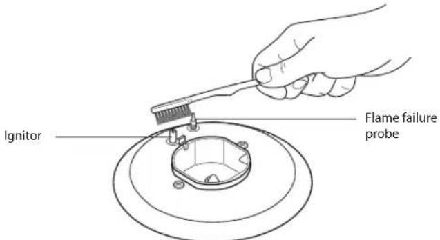
- The ignitors are sparking. If the ignitors are not sparking, they may be dirty or wet. Clean them gently with a small nylon brush such as a toothbrush as shown below. Ensure the electrical supply has been disconnected before cleaning.

To avoid damage to the ignition circuit NEVER light the hob when the burners are not in place.
text_image
Ignitor Flame failure probe
If the Flame is Irregular
If the flame is yellow or irregular, check that the burner parts, including the burner cap (allow to cool before touching), are:
- Clean and dry.
- Positioned correctly. See 'Replacing the Burners'.
• Also see 'Hints and Tips'.

text_image
Burner Cap Electrode Burner Ring
Electricity Failure
If there is an electricity failure, you can still use your hob. Light the burners by holding an ignition source (e.g. candle lighter) close to the side of the burner and turning the control to the High position to light the gas. The controls must still be held down for 5 – 10 seconds after the burner has lit. Releasing the controls too soon will extinguish the flame. Adjust the controls as required.
* All images are for indication only; please refer to your individual unit for actual item.

Cookware Guidelines
To get the best out of your hob, follow these simple suggestions:
- Use saucepans with thick flat bottoms. Food in a saucepan with an uneven bottom will take longer to cook.

text_image
Diagram showing three cooking pots with checkmark and cross symbols below each, likely indicating cooking or testing status.- Do not use large saucepans or frying pans that overlap the edges of your hob as this can deflect heat onto your worktop and damage the surface, and may also cause a hazard.
• Always make sure saucepans are stable. Using very heavy saucepans may bend the trivet/pan support or deflect the flame.
• Always lift the cookware when removing from the hob, do not drag. - When you need to boil, simmer or fry food, first set the temperature to the High position. Once the food is boiling, reduce the temperature to maintain a steady heat to cook your food thoroughly. Doing this will reduce the cooking time and save energy.
• Pan sizes should be as per the table shown below.
| Burners Minimum Diameter Maximum Diameter | |
| Large (130mm) 22 cm 30 cm | |
| Standard (70mm) 14 cm 20 cm | |
| Small (50 mm) 12 cm 18 cm |

natural_image
Two line drawings of a cooking pot with steam rising from its side, showing heating and cooling cycles (no text or symbols)
Do not use cooking vessels on the hob that overlap its edges.
• Using a lid will reduce cooking times and save energy.
- When liquid comes to a boil, reduce the temperature setting to maintain the desired level of boiling.
- Choose cookware of the proper size, material and construction.
- Minimise the amount of liquid or fat to reduce cooking times.
- Select the proper temperature setting for the cooking task.
* All images are for indication only; please refer to your individual unit for actual item.

Cleaning and Maintenance

Steam Cleaners must not be used to clean this product.

To avoid shock hazard, always disconnect the hob from the electrical supply.
| Cooking Part Cleaning Important | ||
| Trivets/pan supports, burner caps and enamel surfaces | Hot soapy water and nylon scourer.Mild abrasive cream cleaners.Fume-free or heavy-duty oven cleaners (follow manufacturer's instructions). | Always allow hob parts to cool completely before cleaning them.Always apply minimal pressure with abrasive cleaners.Remove spills as soon as the hob is cool to avoid the spills becoming burnt on. |
| Burner parts • Hot soapy water.To clear the holes use a stiff nylon brush.Mild abrasive cream cleaners. | Ensure burner parts are dry before refitting.Reassemble the burner parts correctly. | |
| Controls | Hot soapy water and a soft cloth. | Care must be taken if removing the controls from the shafts.If cleaning the controls whilst they are attached to the shaft, ensure liquid does not enter the appliance. |
| Hob surfaces • Soak stains under a hot soapy cloth, rinse and dry thoroughly.Hard water spots can be removed with household white vinegar.Non-abrasive hob surface cleaners. Regular use of a polish designed for use with hobs will reduce fingerprints and other marks. | Never use harsh/abrasive cleaning agents as they will damage the finish.Chlorine or chlorine compounds in some cleaners are corrosive to hob surface and may damage the appearance of your hob. Check the label on the cleaner before using. | |
| Electrodes | Toothbrush. | A dirty or wet electrode will prevent the burner lighting efficiently. Ensure the appliance has been disconnected from the electrical supply before cleaning or drying. |

Cleaning the Gas Hob
| Maintenance Period Description | |
| Daily • Clean gas hob as per the instructions. | |
| Monthly | • Remove all burner parts, and clean using a non-abrasive detergent. Rinse in cold water, dry thoroughly, and replace.• Clean the ignitor and probe carefully, using a toothbrush. |
| Every year | • Contact your local authorized gas Service Agent to perform a thorough check on all gas components on the gas hob. |

Burner Parts and Pan Supports
You can remove and clean these parts with hot soapy water or non-abrasive detergents. Clean spills regularly before they become burnt on. Do not wash these parts in a dishwasher.
After cleaning, check that the burner rings and burner caps are dry before replacing correctly.
It is very important to check that the burner rings and burner caps have been correctly positioned.
Failure to do so can cause serious problems.

To avoid damage to the ignition circuit NEVER light the hob when the burners are not in place.
The surface of the burner cover will gradually lose its gloss finish with time. This is quite normal and will not effect the efficiency of the hob.

Replacing the Burners
Check that:
• The ignitor is always clean to ensure trouble-free sparking.
• The FSD probe is always clean to ensure correct operation of the safety valves.

• Both the ignitor and probe must be very carefully cleaned using a toothbrush.
- When replacing the burner parts, ensure you do not damage the ignitor or temperature probes.

text_image
Technical diagram showing hand positioning of a mechanical component with labeled parts and directional arrows
text_image
Diagram illustrating mechanical assembly steps with arrows indicating direction and a cross symbol indicating disassembly or failure.Burner parts Replacing the burner parts

Hob Controls
If you have problems with the hob controls (gas taps), call your Authorised Service Centre.
These parts are not user serviceable.
* All images are for indication only; please refer to your individual unit for actual item.
| Problem Possible Solutions | |
| My burner does not light | Check the hob is plugged in and the electricity is switched on.Check the gas supply valve is turned on and the gas supply to the house is working. You should hear the gas when you turn a burner on.The ignitors may be dirty. Clean gently with a small nylon brush such as a toothbrush.The burner parts may not be located properly. Check the assembly and make sure the burner cap is sitting flat. |
| My burner flames are yellow or hard to start | The burner parts may not be located properly. Check the assembly and make sure the burner cap is sitting flat.If you use bottled gas this may indicate you are getting near the end of the bottle.Check the burner parts are clean and dry.The gas pressure may not be at the correct level. Check with your approved service agent.Your hob may not be set up for the gas you are using. Check this with your approved service agent or installer. |
| One of my burners has an uneven flame | Check the burner parts are clean and dry. Check the assembly and make sure the burner cap is sitting flat. |
| My burner goes out when I let go of the control | The hob has a safety feature called ‘Flame Supervision Device (FSD)’. Hold down the control for approximately 5 – 10 seconds after the burner has lit. Releasing the control too soon will extinguish the flame. See the ‘Flame Failure Safety Feature’ section. |
| The flame goes out at low settings | The gas supply pressure may be low. Check this with your approved service agent.The low setting may have been adjusted incorrectly. Check this with your approved service agent. |
| My burners do not turn down much (when running on bottled gas or LPG) | Your burners may not have been adjusted correctly. Check this with your approved service agent. |
| The flame tips are very yellow | Call your approved service agent. |
| There are objectionable odours | Call your approved service agent.Ensure the hob and burners are clean and dry. |
| The flame appears to lift off the burner | Call your approved service agent. |
| There is an electricity failure | If there is an electricity failure, you can still use your hob. Light the burners by holding a candle lighter close to the side of the burner and turning the control to the High position. Wait until the flame is burning evenly before adjusting. The control must still be held down for 5 – 10 seconds after the burner has lit. Releasing the control too soon will extinguish the flame. |

Specifications
| Brand Logik | |
| Model LGHOBX16 | |
| Supply Voltage 220-240 V~50 Hz | |
| Power Consumption(W) 1 | |
| Gas Type NG or LPG (Default set to NG) | |
| Net Weight (kg) 8.5 | |
| Product Dimensions (cm) | |
| External Width | 58 |
| External Depth | 51 |
| Product Dimensions (cm) | |
| Internal Width | 56 |
| Internal Depth | 48-49 |
| Type of Hob Gas | |
| Number of Cooking Zones 4 | |
| Energy Efficiency of Hob 57.66% | |
| Number of Cooking Zones (Hob) 4 | |
| Heating Zone(s) - Auxiliary (Front Right) | |
| Heating Technology Gas | |
| Energy Efficiency N/A | |
| Heating Zone(s) - Semi-Rapid x2 (Rear left & Right) | |
| Heating Technology Gas | |
| Energy Efficiency 58% | |
| Heating Zone(s) - Rapid x1 (Front Left) | |
| Heating Technology Gas | |
| Energy Consumption 57% | |
| Energy Efficiency of Hob | 57.66% |
| This Hob Complies with | EN 30-2-1 |
Features and specifications are subject to change without prior notice.

Table for the Choice of the Injectors
| Burner Injector Values According To The Gas Type | LPG Natural Gas | |||
| G 30/3128-30/37 mBar | G 2020 mBar | |||
| Large Burner (130mm) | Injector mm 0.92 | 1.32 | ||
| Power kW 3.30 | 3.30 | |||
| Standard Burner (70mm) | Injector mm 0.66 | 0.97 | ||
| Power kW 1.75 | 1.75 | |||
| Small Burner (50mm) | Injector mm 0.50 | 0.78 | ||
| Power kW 1.00 | 1.00 | |||

- All intervention regarding installation maintenance and conversion of the appliance must be fulfilled with original factory parts.
• The manufacturer declines any liability if these correct parts are not used.

Installation

The hob must be installed by a Gas Safe Registered engineer in accordance with the Gas Safety (Installation and Use) Regulations and to the relevant standards. Please, ensure that, once the hob is installed, it is easily accessible for the engineer in the event of a breakdown.
- Prior to installation, ensure that the local distribution conditions (nature of gas and pressure) and the adjustment of the product are compatible. The adjustment conditions for this product are stated on the data plate.
- Ensure that there is a mains socket within reach of the hob cable (1500 mm from the rear right of the product). This must be accessible after installation or an all-pole disconnection switch must be provided in the fixed wiring in accordance with the local wiring regulations. The mains cable must not touch any metal parts.
- Ensure that your kitchen worktop is designed for use in a kitchen.
- This appliance is not connected to a combustion products evacuation device. It shall be installed and connected in accordance with current installation regulations. Particular attention shall be given to the relevant requirements regarding ventilation.

Wiring
Should the mains lead of the appliance ever require replacing, we recommend that this be carried out by a qualified electrician who will replace it with a lead of the same size and temperature rating.

This appliance must be earthed.
The flexible mains lead is supplied connected to a BS1363 fused plug, having a fuse of 3Amp capacity. If this plug does not fit the socket in your home, it should be replaced with a suitable plug as outlined below.
The wires in the mains lead are coloured in accordance with the following code:
Green & Yellow = Earth
Blue = Neutral
Brown = Live
-
The wire which is coloured green and yellow must be connected to the terminal marked E ( 12 ) Earth.
-
The wire which is coloured blue must be connected to the terminal marked N (Neutral).
-
The wire which is coloured brown must be connected to the terminal marked L (Live).
-
Ensure all screws are adequately tightened. Do not over tighten as you may risk damaging the screw threads.
The plug and socket must be accessible after installation, or an all-pole disconnection switch provided in the fixed wiring in accordance with the local wiring regulations.

text_image
L E N
Ventilation Requirements
- This appliance is not connected to a combustion products evacuation device. It should be installed and connected in accordance with current installation regulations. Particular attention should be given to the relevant requirements regarding ventilation.
- The appliance should be installed in a room or space with an air supply in accordance with the latest edition of BS5440-2.
- For rooms with a volume of less than 5m^3 — permanent ventilation of 100cm^2 free area will be required.
- For rooms with a volume of between 5 ^m and 10 m^3 a permanent ventilation of 50 cm^2 free area will be required unless the room has a door which opens directly to the outside air in which case no permanent ventilation is required.
- For rooms with a volume greater than 10m— no permanent ventilation is required.
- For a cellar or basement with a volume of 10m^3 — permanent ventilation of 65cm^2 free area will be required.

- Regardless of room size, all rooms containing the appliance must have direct access to the outside air via a window that opens or equivalent.
- Where there are other fuel burning appliances in the same room, the latest edition of BS 5440-2 should be consulted to determine the correct amount of free area ventilation requirements.

Gas Installation

This cooker uses and is ready to use NATURAL GAS only and cannot be used with any other gas without modification. This appliance is manufactured for conversion to LPG after fitting new injectors, new supply hose and making adjustments. Refer to “replacement of burner injectors” section for details.

Installation and Service Regulations

This appliance must be installed and serviced only by a suitably qualified and Gas Safe Registered engineer, and in accordance with the current editions of the following standards and regulations or other locally applicable regulations:
Gas Safety (Installation and Use) Regulations
Building Regulations
British Standards (BS 5440, BS 6172 and BS 6891)
Regulations for Electrical Installation (BS 7671, (Latest Edition))

Location
The hob should be located in a kitchen or kitchen/diner, but not in a bathroom, shower room, garage or a bed sitting room with a volume less than 20 cubic metres.
Do not install this appliance in a room below ground level unless it is open to ground level on at least one side.
Before making the cut out in the worktop ensure that there is a minimum distance of 60 mm between the rear edge of the hob and the wall. If there are non-combustible materials (ceramic tiles, metal backsplash etc.) on the wall then this can be reduced to 40 mm.
A minimum distance of 300 mm must be left between the side edges of the hob and any adjacent cabinets or walls. If there are non-combustible materials (ceramic tiles, metal backsplash etc.) on the wall then this can be reduced to 50 mm.
The minimum distance combustible material can be fitted above the hob in line with the edges of the hob is 400 mm.
The minimum distance combustible material can be fitted directly above the hob is 750 mm.

The use of a gas cooking appliance results in the production of heat, moisture and products of combustion in the room in which it is installed. Ensure that the kitchen is well ventilated especially when the appliance is in use: keep natural ventilation holes open or install a mechanical ventilation device (mechanical extractor hood). Prolonged intensive use of the appliance may call for additional ventilation, e.g. opening of a window, or more effective ventilation, e.g. increasing the level of mechanical ventilation where present.
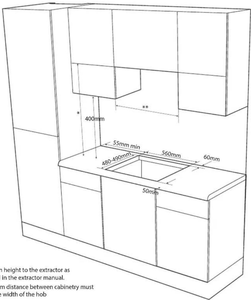
text_image
400mm 55mm min 480-490mm 560mm 60mm 50mm **h height to the extractor as in the extractor manual. m distance between cabinetry must width of the hob
When the Hob is First Installed
Once the hob has been installed, it is important to remove any protective materials, which were put on in the factory.
Any gas installation must be carried out by a Gas Safe Registered engineer.
The manufacturer will not accept liability, should the above instructions or any of the other safety instructions incorporated in this manual are ignored.
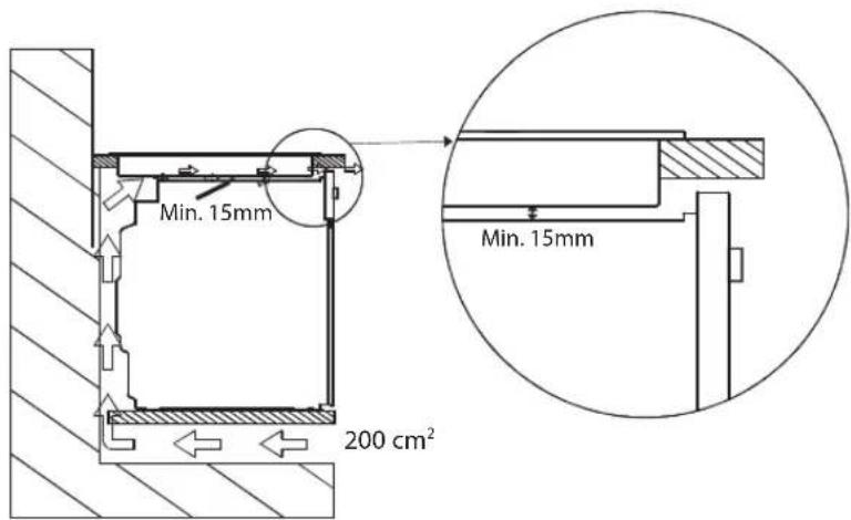
text_image
Min. 15mm 200 cm² Min. 15mmIf you are not fitting the hob above an oven, you must install a heat resistant barrier (minimum of 15mm below the hob) to separate the hob from the cabinet.

text_image
Min 15mm from hob base Heat resistant barrier
Gas Connection
Connection to the gas supply should be with a rigid pipe, i.e. steel or copper. The connection should be suitable for connecting to 1/2 BSP male thread. When the final connection has been made, it is essential that a thorough leak test is carried out on the hob and installation. Ensure that all pipework is not under any strain or stress.
1: End of manifold with 1/2 BSP male thread
2: Washer
3: 90 degree connection elbow
- All connections must be made by a qualified Gas Safe engineer.

Failure to ensure the correct assembly will cause leakage of gas.

text_image
1 2 3* All images are for indication only; please refer to your individual unit for actual item.

Cut Out Dimensions
The dimensions of the cut-out are given in the diagram.
Width: 560mm Depth: 480-490mm

All measurements given in millimetres (mm) and cutout dimensions are given as: 'nominal measurement'
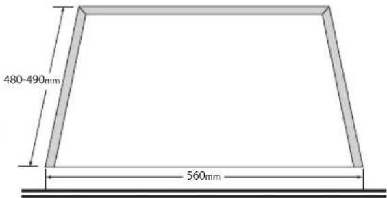
text_image
480-490mm 560mmProduct Overall Dimensions
Width: 580mm Depth: 510mm

Fitting the Hob into the Worktop
• Run the sealant around the rim of the hob.
- Insert the appliance into the aperture and fix in position using the fixing plate and screws. Your appliance has multiple points where you can attach the fixing brackets.
Fixing Points
The 4 fixing points are shown below.

text_image
Apply the seal to the edge of the hob.Attaching the fixing brackets
Your hob is supplied with 4 fixing brackets and 4 screws. You can attach the fixing brackets to any of the fixing positions. If you worktop is not thick enough for the fixing bracket to make contact with add a separate piece of wood (as shown below) to make up the thickness. Be careful not to over tighten the screws.

natural_image
Pure diagram of a mechanical or electrical component with no text, numbers, or symbols
Do NOT over tighten the screws
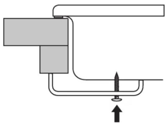
natural_image
Pure mechanical diagram showing a lever and screw with an upward arrow, no text or symbols presentAdd an extra piece of wood to make the worktop thicker if necessary.
Check the Hob After Installation & Before Using

- If the appliance is to be installed above a cupboard or drawer it is absolutely essential that you place a separating board between the base of the appliance and the drawer unit.
- This must be fixed in place 60 mm below the hob to prevent accidental contact with the bottom of the hob which may be hot.
When the hob has been fully installed it will be necessary to check the minimum flame setting. To do this, follow the step below,
• Turn the gas tap to the MAX position and ignite
- Set the gas tap to the MIN flame position then turn the control from MIN to MAX several times. If the flame is unstable or is extinguished follow the procedure below.
Pressure Testing
- Remove the left hand pan support and front left burner cap and crown.
- Fit manometer tube over the injector.
- Turn on the burner gas supply and ignite all the other burners.
- Turn off the burner supplies.
* All images are for indication only; please refer to your individual unit for actual item.

Conversion from NG to LPG or from LPG to NG

The replacement / conversion of the gas hob should only be undertaken by Gas Safe Registered Engineer. The hob is supplied for use with Natural Gas only and cannot be used on any other gas without modification. It can be converted from NG to LPG or LPG to NG providing the correct injectors are fitted and the gas rate is adjusted to suit.
Natural Gas
- In the United Kingdom flexible connections must not be used for built in product, rigid or semi-rigid pipework must be used.
LP Gas
- In the United Kingdom flexible type hoses must not be used for built in products, rigid or semi-rigid pipework must be used. Ensure it is suitable for use on LP Gas up to 50mbar pressure rise.
- In all other countries this appliance must be installed in accordance with local regulations and standards.
Method
- Ensure that the gas taps are in the "●" position
- Isolate the hob from the electrical supply
- Remove all pan supports, burner caps, rings, crowns and controls.
- With the aid of a 7mm box spanner the burner injectors can then be unscrewed and replaced by the appropriate injectors. See the Burner configuration Table for details. Note the size of the injector being removed to ensure the corresponding size of the new injector is used, NG vs LPG.

natural_image
Technical line drawing of a mechanical assembly with a central shaft and base mount (no text or symbols)
To Adjust the Gas Rate
With the aid of a thin bladed screwdriver completely tighten down the bypass adjustment screw, which is located down the centre of the gas tap control shaft or on the gas tap body. See further adjustments in the next section.
Upon completion stick the replacement rating plate sticker on the under side of the hob.

Minimum Setting or Turn Down
This unit has been set at the factory for NG but can be checked after the correct pressure has been reached.
To adjust the minimum setting you will need a ∅ 2.5mm x 45mm screwdriver.
-
Ignite the burner and set the control to its minimum position.
-
Remove the control.
3. FOR NG (G20 G25)
Rotate the turn down screw slowly until a minimum regular flame is achieved. (The flame will diminish when the screw is turned clockwise and increase when turned anti-clockwise.
FOR LP Gas (G30 G31)
Rotate the turn down screw clockwise until it comes to a stop, this is the fixed turn down position for LP Gas.
-
Replace the control.
-
When the setting is right check regulation by quickly rotating the control from the maximum to the minimum delivery position. The flame must not go out and remain stable throughout the range.

Burner Configuration
| Gas Category | LPG (Supplied in accessory pack) NG (Fitted on unit) | |
| G30/31 G20 | ||
| GB: II_2H/3 + 28 - 30/37 mbar 20 mbar | ||
| Large Burner (Front Left) | ||
| Injector dia. (mm) 0.92 1.32 | ||
| Nominal Rating (kw) 3.30 3.30 | ||
| Consumption in 1 h(at 15°C and 1013 mbar press) | 239.9 gr/h | 314.1 lt/h |
| Small Burner (Front Right) | ||
| Injector dia. (mm) 0.50 0.78 | ||
| Nominal Rating (kw) 1.00 1.00 | ||
| Consumption in 1 h(at 15°C and 1013 mbar press) | 72.7 gr/h | 95.2 lt/h |
| Medium Burner (Rear Left And Right) | ||
| Injector dia. (mm) 0.66 0.97 | ||
| Nominal Rating (kw) 1.75 1.75 | ||
| Consumption in 1 h(at 15°C and 1013 mbar press) | 127.2 gr/h | 166.7 lt/h |

For general information about this appliance and handy hints and tips, please visit www.knowhow.com/knowledgebank or call 0344 5611234.

Visit Partmaster.co.uk today for the easiest way to buy electrical spares and accessories. With over 1 million spares and accessories available we can deliver direct to your door the very next day. Visit www.partmaster.co.uk or call 0344 800 3456 (UK customers only). Calls charged at National Rate.
The symbol on the product or its packaging indicates that this product must not be disposed of with your other household waste. Instead, it is your responsibility to dispose of your waste equipment by handing it over to a designated collection point for the recycling of waste electrical and electronic equipment. The separate collection and recycling of your waste equipment at the time of disposal will help conserve natural resources and ensure that it is recycled in a manner that protects human health and the environment.
For more information about where you can drop off your waste for recycling, please contact your local authority, or where you purchased your product.
DSG Retail Ltd. (co. no. 504877) 1 Portal Way, London, W3 6RS, UK
IB-LGHOBX16-160711V1