LGHOBX10 - Cooker Logik - Free user manual and instructions
Find the device manual for free LGHOBX10 Logik in PDF.
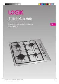


| Product Type | Freestanding Cooker |
| Brand | Logik |
| Model | LGHOBX10 |
| Energy Source | Gas Hob / Electric Oven |
| Dimensions (H x W x D) | 90 x 60 x 60 cm |
| Weight | Approx. 50 kg |
| Power Supply | 230 V ~ 50 Hz |
| Oven Capacity | 65 L |
| Oven Functions | Conventional, Grill, Fan, Defrost |
| Hob Burners | 4 Gas Burners (1 large, 2 medium, 1 small) |
| Ignition | Automatic Electric Ignition |
| Cleaning | Enamel interior; removable oven door |
| Safety Features | Flame failure safety device on hob; child lock |
| Spare Parts Availability | Oven shelves, burner caps, knobs, heating elements |
| Repairability Index | 7.5 / 10 (estimated) |
| Energy Efficiency Class | A (estimated) |
| Color | White / Silver (varies) |
| Control Type | Knobs and push-buttons |
| Timer | Yes, mechanical timer |
| Included Accessories | 1 oven shelf, 1 dripping pan, gas hose |
Frequently Asked Questions - LGHOBX10 Logik
User questions about LGHOBX10 Logik
0 question about this device. Answer the ones you know or ask your own.
Ask a new question about this device
Download the instructions for your Cooker in PDF format for free! Find your manual LGHOBX10 - Logik and take your electronic device back in hand. On this page are published all the documents necessary for the use of your device. LGHOBX10 by Logik.
USER MANUAL LGHOBX10 Logik
Contents
Contents 3
Unpacking 4
Product Overview....5
The Main Unit....5
Control Panel....5
Before Using Your New Hob 6
Lighting the Hob....6
Flame Failure Safety Feature 7
If the Burner Does Not Light....7
If the Flame is Irregular 7
Electricity Failure....7
Cookware Guidelines 8
Cleaning and Maintenance....9
Cleaning the Gas Hob 9
Burner Parts and Pan Supports 10
Replacing the Burners....10
Hob Controls 10
Hints and Tips 11
Specification 12
Burner Values....12
Installation....13
Wiring 13
Provision for Ventilation 14
Location....14
When the Hob is First Installed.... 15
Gas Connection....15
Cut Out Dimensions 16
Overall Dimensions....16
Fitting the Hob into the Worktop 16
Check the Hob After Installation & Before Using 16
Pressure Testing 16
Conversion from NG to LPG or from LPG to NG 17
Natural Gas....17
LP Gas 17
Method....17
To Adjust the Gas Rate 17
Minimum Setting or Turn Down 18
Burner Configuration 18
Gas Category....19
Safety Warnings....20
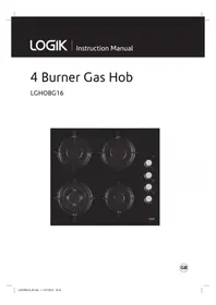
Thank you for purchasing your new Logik Built-in Gas Hob.
You must read this manual in order to fully understand how to operate it correctly.
This unit MUST be installed by a competent and registered engineer (Gas Safe in the UK).
Please allow the installer to view the installation section of this manual.
Read all the safety warnings carefully before use and keep this manual for future reference.

Unpacking
Remove all packaging from the unit. Retain the packaging. If you dispose of it, please do so according to local regulations.
The following items are included:
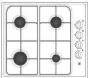
Main Unit
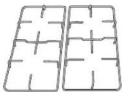
Pan Support (Left/Right) × 2 P.N.: Left - 37002036 Right - 37002037
LPG Nozzle Installation Guide × 1 P.N.: 52007667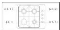
LPG Replacement Rating Plate Sticker × 1 P.N.: 20628175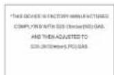
100 mm Burner Ring × 1 P.N.: 37001476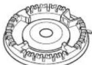
75 mm Burner Ring × 2 P.N. 37001477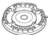
55 mm Burner Ring × 1 P.N. 37001478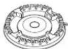
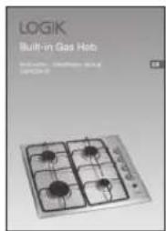
Instruction / Installation Manual P.N.: 52036601-V2
100 mm Burner Cap × 1 P.N.: 37001479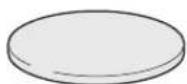
75 mm Burner Cap × 2 P.N.: 37001480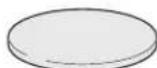
55 mm Burner Cap × 1 P.N.: 37001481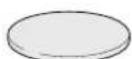
LPG Conversion Kit: Fixing Plate × 4 P.N.: 37001970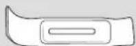
Screw × 4 P.N.: 37002652
LPG Nozzle × 4 P.N.: ∅ 100 37001482 ∅75 37001483 ∅ 55 37001484
Seal × 1 P.N.: 62000705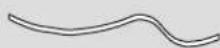

If items are missing or damaged, please contact Partmaster (UK only).
Tel: 0844 800 3456 for assistance.

Product Overview
The Main Unit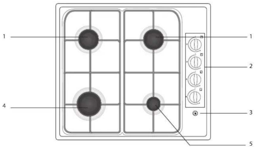
- Standard burner (75 mm)
- Control panel
- Ignition button
- Large burner (100 mm)
- Small burner (55 mm)
Control Panel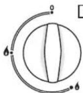
To select upper right burner
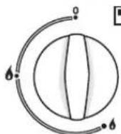
To select upper left burner
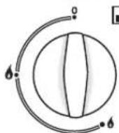
To select lower left burner
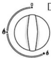
To select lower right burner

Before Using Your New Hob
Before using your new hob, please:
- Read this manual fully, taking special note of the 'Safety Warnings' section.
- Plug the hob into the electricity supply and turn it on so that the ignition circuit will work.

This appliance is for cooking purposes only. It must not be used for other purposes, e.g. room heating.

Lighting the Hob
- Choose the control for the burner you want to use.
- Press the control down gently and turn it anti-clockwise to the large flame symbol ⬆ while pressing the ignition button.
The ignitors on all burners will spark. Only the burner you have selected will light.
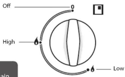

- If the burner does not light up within 15 seconds, turn the control off and wait for at least one minute before trying again.
- To switch the burner off, turn the control clockwise to the 0 position. After use, always turn the controls to the off position.
- Once the burner is lit, release the ignition button but keep holding the control for approximately 5 – 10 seconds after the flame has lit to ensure the Flame Supervision Device (FSD) operates.
- With the control no longer pressed in, you can continue turning it towards the small flame symbol, depending on the setting you want to cook with. Always adjust the flame for cooking between the small and large flame, never between the large flame and off.
- Control the flame so that it does not spread out beyond the side of the pan, as the outer part of the flame is much hotter.

If the flame goes out turn the burner off, wait 60 seconds and then repeat the procedure above.
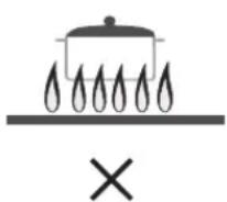
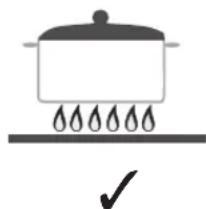
| Gentle simmering, slow warming,reheating and rapid simmering | |
| Boiling, sauté and searing –maximum heat |

The use of a gas cooking appliance results in the production of heat, moisture and products of combustion in the room in which it is installed. Ensure that the kitchen is well ventilated especially when the appliance is in use: keep natural ventilation holes open or install a mechanical ventilation device (mechanical extractor hood). Prolonged intensive use of the appliance may call for additional ventilation, e.g. opening of a window, or more effective ventilation, e.g. increasing the level of mechanical ventilation where present.

Flame Failure Safety Feature
The flame supervision device (FSD) probe cuts off the gas supply to the burner if the flame is blown out.
When lighting the burner, hold down the control for approximately 5 – 10 seconds after the burner has lit. Releasing the control too soon will extinguish the flame.
If the flames are accidentally extinguished, turn off the burner and do not try to light it again for at least one minute (to allow the gas to disperse).

If the Burner Does Not Light
If the burner does not light, check that:
• The hob is switched on. • The gas is turned on. • You have held down the control for at least 5 – 10 seconds. - The ignitors are sparking. If the ignitors are not sparking, they may be dirty or wet. Clean them gently with a small nylon brush such as a toothbrush as shown below.
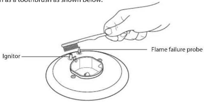

To avoid damage to the ignition circuit NEVER light the hob when the burners are not in place.

If the Flame is Irregular
• If the flame is yellow or irregular, check that the burner parts, including the burner cap, are: - Clean and dry. - Positioned correctly. See 'Replacing the Burners'. • Also see 'Hints and Tips'.
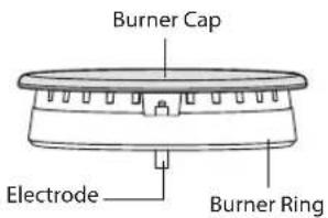
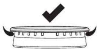
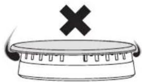

Electricity Failure
If there is an electricity failure, you can still use your hob. Light the burners by holding an ignition source (e.g. candle lighter) close to the side of the burner and turning the control to the High position to light the gas. The controls must still be held down for 5 – 10 seconds after the burner has lit. Releasing the controls too soon will extinguish the flame. Adjust the controls as required.

Cookware Guidelines
To get the best out of your hob, follow these simple suggestions:
- Use saucepans with thick flat bottoms. Food in a saucepan with an uneven bottom will take longer to cook.
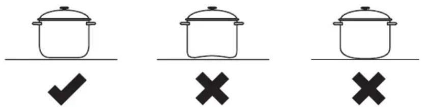
- Do not use large saucepans or frying pans that overlap the edges of your hob as this can deflect heat onto your worktop and damage the surface.
- Always make sure saucepans are stable. Using very heavy saucepans may bend the trivet/pan support or deflect the flame. • Always lift the cookware when removing from the hob, do not drag.
- When you need to boil, simmer or fry food, first set the temperature to the High position. Once the food is boiling, reduce the temperature to maintain a steady heat to cook your food thoroughly. Doing this will reduce the cooking time. • Pan sizes should be as per the table shown below.
| Burners Minimum Diameter Maximum Diameter | |
| Large (100mm) 22 mm 26 mm | |
| Standard (75mm) 14 mm 22 mm | |
| Small (55 mm) 12 mm 18 mm |
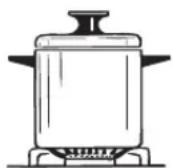
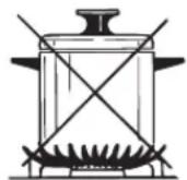

Do not use cooking vessels on the hob that overlap its edges.
• Using a lid will reduce cooking times. - When liquid comes to the boil reduce the temperature setting. - Choose cookware of the proper size, material and construction. - Minimise the amount of liquid or fat to reduce cooking times. - Select the proper temperature setting for the cooking task.

Cleaning and Maintenance

Steam Cleaners must not be used to clean this product.
| Cooking part Cleaning Important | ||
| Trivets/pan supports, burner caps and enamel surfaces | Hot soapy water and nylon scourer.Mild abrasive cream cleaners.Fume-free or heavy-duty oven cleaners (follow manufacturer's instructions). | Always allow hob parts to cool completely before cleaning them.Always apply minimal pressure with abrasive cleaners.Remove spills as soon as the hob is cool to avoid the spills becoming burnt on. |
| Burner parts • Hot soapy water.To clear the holes use a stiff nylon brush.Mild abrasive cream cleaners. | Ensure burner parts are dry.Reassemble the burner parts correctly. | |
| Controls • Hot soapy water and a soft cloth. | ||
| Hob surfaces • Soak stains under a hot soapy cloth, rinse and dry thoroughly.Hard water spots can be removed with household white vinegar.Non-abrasive hob surface cleaners. Regular use of a polish designed for use with hobs will reduce fingerprints and other marks. | Never use harsh/abrasive cleaning agents as they will damage the finish.Chlorine or chlorine compounds in some cleaners are corrosive to hob surface and may damage the appearance of your hob. Check the label on the cleaner before using. | |
| Electrodes • Toothbrush. • A dirty or wet electrode will prevent | the burner lighting efficiently. | |

Cleaning the Gas Hob
| Maintenance Period Description | |
| Daily • Clean gas hob as per the instructions. | |
| Monthly • Remove all burner parts, and clean using a non-abrasive detergent. Rinse in cold water, dry thoroughly, and replace.• Clean the ignitor and probe carefully, using a toothbrush. | |
| Every year • Contact your local authorized gas Service Agent to perform a thorough check on all gas components on the gas hob. |

Burner Parts and Pan Supports
You can remove and clean these parts with hot soapy water or non-abrasive detergents. Clean spills regularly before they become burnt on. Do not wash these parts in a dishwasher.
After cleaning, check that the burner rings and burner caps are dry before replacing correctly.
It is very important to check that the burner rings and burner caps have been correctly positioned.
Failure to do so can cause serious problems.

To avoid damage to the ignition circuit NEVER light the hob when the burners are not in place.
The surface of the burner cover will gradually lose its gloss finish with time. This is quite normal and will not affect the efficiency of the hob.

Replacing the Burners
Check that:
• The ignitor is always clean to ensure trouble-free sparking. • The FSD probe is always clean to ensure correct operation of the safety valves.

• Both the ignitor and probe must be very carefully cleaned using a toothbrush. - When replacing the burner parts, ensure you do not damage the ignitor or temperature probes.
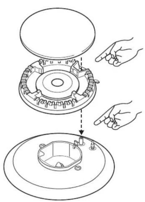
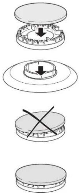
Burner parts Replacing the burner parts

Hob Controls
If you have problems with the hob controls (gas taps), call your Authorised Service Centre.
These parts are not user serviceable.

Hints and Tips
| Problem Possible Solutions | |
| My burner does not light | Check the hob is plugged in and the electricity is switched on.Check the gas supply valve is turned on and the gas supply to the house is working. You should hear the gas when you turn a burner on.The ignitors may be dirty. Clean gently with a small nylon brush such as a toothbrush.The burner parts may not be located properly. Check the assembly and make sure the burner cap is sitting flat. |
| My burner flames are yellow or hard to start | The burner parts may not be located properly. Check the assembly and make sure the burner cap is sitting flat.If you use bottled gas this may indicate you are getting near the end of the bottle.Check the burner parts are clean and dry.The gas pressure may not be at the correct level. Check with your approved service agent.Your hob may not be set up for the gas you are using. Check this with your approved service agent or installer. |
| One of my burners has an uneven flame | Check the burner parts are clean and dry. Check the assembly and make sure the burner cap is sitting flat. |
| My burner goes out when I let go of the control | The hob has a safety feature called ‘Flame Supervision Device (FSD)’. Hold down the control for approximately 5 – 10 seconds after the burner has lit. Releasing the control too soon will extinguish the flame. See the ‘Flame Failure Safety Feature’ section. |
| The flame goes out at low settings | The gas supply pressure may be low. Check this with your approved service agent.The low setting may have been adjusted incorrectly. Check this with your approved service agent. |
| My burners do not turn down much (when running on bottled gas or LPG) | Your burners may not have been adjusted correctly. Check this with your approved service agent. |
| The flame tips are very yellow | Call your approved service agent. |
| There are objectionable odours | Call your approved service agent. |
| The flame appears to lift off the burner | Call your approved service agent. |
| There is an electricity failure | If there is an electricity failure, you can still use your hob. Light the burners by holding a candle lighter close to the side of the burner and turning the control to the High position. Wait until the flame is burning evenly before adjusting. The control must still be held down for 5 – 10 seconds after the burner has lit. Releasing the control too soon will extinguish the flame. |
Specification
| Model LGHOBX10 | |
| Rated Voltage (V) 230 | |
| Rated Frequency (Hz) 50 | |
| Power Consumption(W) 1 | |
| Gas Type NG or LPG (Default set to NG) | |
| Net Weight (kg) 7.5 | |
| Product Dimensions (cm) | |
| External Width | 58 |
| External Depth | 51 |
| Product Dimensions (cm) | |
| Internal Width | 55 |
| Internal Depth | 48 |
Features and specifications are subject to change without prior notice.
Burner Values
| Burner Power Output | LPG Natural Gas | |
| G 30-30 mBar | G 20-20 mBar | |
| Large Burner (100 mm) 3 kW 3 kW | ||
| Standard Burner (75 mm) 1.75 kW 1.75 kW | ||
| Small Burner (55 mm) 1 kW 1 kW | ||

Installation

The hob must be installed by a Gas Safe Registered engineer in accordance with the Gas Safety (Installation and Use) Regulations and to the relevant standards. Please, ensure that, once the hob is installed, it is easily accessible for the engineer in the event of a breakdown.
- Prior to installation, ensure that the local distribution conditions (nature of gas and pressure) and the adjustment of the product are compatible. The adjustment conditions for this product are stated on the data plate.
- Ensure that there is a mains socket within reach of the hob cable (1600 mm from the rear right of the product). This must be accessible after installation or an all-pole disconnection switch must be provided in the fixed wiring in accordance with the local wiring regulations. The mains cable must not touch any metal parts. • Ensure that your kitchen worktop is designed for use in a kitchen.
- This appliance is not connected to a combustion products evacuation device. It shall be installed and connected in accordance with current installation regulations. Particular attention shall be given to the relevant requirements regarding ventilation.

Wiring
Should the mains lead of the appliance ever require replacing, we recommend that this be carried out by a qualified electrician who will replace it with a lead of the same size and temperature rating.

This appliance must be earthed.
The flexible mains lead is supplied connected to a BS1363 fused plug, having a fuse of 13Amp capacity. If this plug does not fit the socket in your home, it should be replaced with a suitable plug as outlined below.
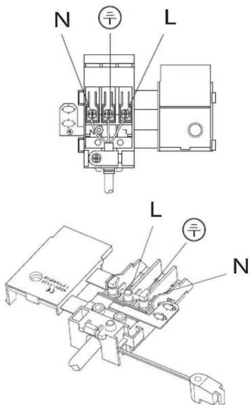
The wires in the mains lead are coloured in accordance with the following code:

Green & Yellow = Earth
Blue = Neutral
Brown = Live
- The wire which is coloured green and yellow must be connected to the terminal marked E (Earth).
- The wire which is coloured blue must be connected to the terminal marked N (Neutral).
- The wire which is coloured brown must be connected to the terminal marked L (Live).
- Ensure all screws are adequately tightened. Do not over tighten as you may risk damaging the screw threads.
The plug and socket must be accessible after installation, or an all-pole disconnection switch provided in the fixed wiring in accordance with the local wiring regulations.

Provision for Ventilation
• The room containing the appliance should have an air supply in accordance with the latest version of BS5440. - All rooms require a window that opens or equivalent, while some rooms require a permanent vent in addition to the window that opens. - The appliance should not be installed in a bed sitting room of volume less than 20 cubic metres. - If it is installed in a room of volume less than 5 cubic metres an air vent of effective area 100 square centimetres is required. - If it is installed in a room of volume between 5 cubic metres and 10 cubic metres, an air vent of effective area 50 square centimetres is required, however, if the room has a door that opens directly to the outside, no air vent is required even when the room volume is between 5 cubic metres and 10 cubic metres. • If the volume exceeds 10 cubic metres, no air vent is required.

Location
The hob should be located in a kitchen, a kitchen/diner or bed sitting room, but not in a bathroom, shower room or garage.
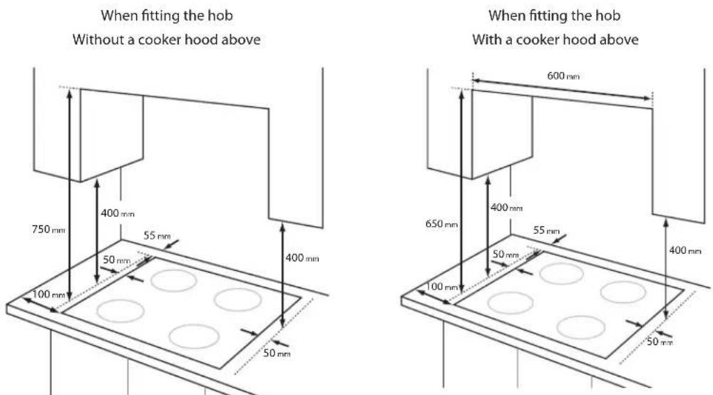
Before making the cut out in the worktop ensure that there is a minimum distance of 55 mm between the rear edge of the hob and the wall.
A minimum distance of 100 mm must be left between the side edges of the hob and any adjacent cabinets or walls.
The minimum distance combustible material can be fitted above the hob in line with the edges of the hob is 400 mm.
If it is fitted below 400 mm, a space of 50 mm must be allowed from the edges of the hob.
The minimum distance combustible material can be fitted directly above the hob is 650 mm with a cooker hood above and 750 mm without a cooker hood above.

The use of a gas cooking appliance results in the production of heat, moisture and products of combustion in the room in which it is installed. Ensure that the kitchen is well ventilated especially when the appliance is in use: keep natural ventilation holes open or install a mechanical ventilation device (mechanical extractor hood). Prolonged intensive use of the appliance may call for additional ventilation, e.g. opening of a window, or more effective ventilation, e.g. increasing the level of mechanical ventilation where present.

When the Hob is First Installed
Once the hob has been installed, it is important to remove any protective materials, which were put on in the factory.
Any gas installation must be carried out by a Gas Safe Registered engineer.
The manufacturer will not accept liability, should the above instructions or any of the other safety instructions incorporated in this manual are ignored.
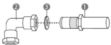
The end of the manifold includes a Rc 1/2 and Rp 1/2 threaded elbow. The elbow has an arrow sign to show the direction of gas flow. If the elbow is disassembled for any reason, the arrow direction must be respected during re-assembly. The arrow head should point towards the appliance. There is a washer fitted between these components, if any adjustments are made ensure parts are screwed together without using excessive force.
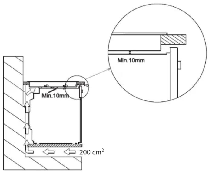
If the hob is going to be installed on the top of a built in oven without forced cooling ventilation, proper air vents must be installed to guarantee adequate ventilation, with the lower air entering with a cross section of at least 200 cm², and the higher air exiting with a cross section of at least 60 cm².

Gas Connection
Connection to the gas supply should be with either rigid or semi-rigid pipe, i.e. steel or copper. The connection should be suitable for connecting to 1/2 BSP male thread. When the final connection has been made, it is essential that a thorough leak test is carried out on the hob and installation. Ensure that the main connection pipe does not exert any strain on the hob.
It is important to install the elbow correctly, with the shoulder on the end of the thread, fitted to the hob connecting pipe. Failure to ensure the correct assembly will cause leakage of gas.
1: End of manifold with 1/2 BSP male thread 2: 90 degree connection elbow 3: Washer

Cut Out Dimensions
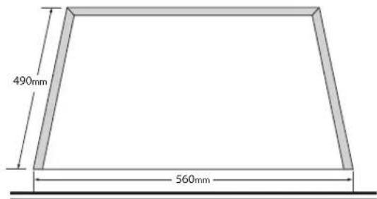
The dimensions of the cut-out are given in the diagram.
Width: 560mm Depth: 490mm

All measurements given in millimetres (mm) and cutout dimensions are given as: 'nominal measurement'
Overall Dimensions
Width: 580mm Depth: 510mm

Fitting the Hob into the Worktop
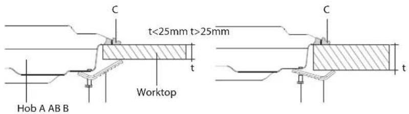
- Apply the adhesive sealing material "C" all the way round the aperture on the worktop to match the outer perimeter edge of the appliance. Ensure that the junctions overlap at the corners and no gap is left along the sealing material.
- Insert the appliance into the aperture and fix in position using the brackets and screws. Adjust the position of the brackets depending on the thickness of the worktop as indicated below and tighten the screws evenly.
- Carefully trim away the excess sealing material "C" from around the appliance.

- If the appliance is to be installed above a cupboard or drawer it is absolutely essential that you place a separating board between the base of the appliance and the drawer unit.
- This must be fixed in place 60 mm below the hob to prevent accidental contact with the bottom of the hob which may be hot.
Check the Hob After Installation & Before Using
When the hob has been fully installed it will be necessary to check the minimum flame setting. To do this, follow the step below,
• Turn the gas tap to the MAX position and ignite - Set the gas tap to the MIN flame position then turn the control from MIN to MAX several times. If the flame is unstable or is extinguished follow the procedure below.
Pressure Testing
- Remove the left hand pan support and front left burner cap and crown.
- Fit manometer tube over the injector.
- Turn on the burner gas supply and ignite all the other burners.
- Turn off the burner supplies.

Conversion from NG to LPG or from LPG to NG

The replacement / conversion of the gas hob should only be undertaken by a Gas Safe Registered Engineer. The hob is supplied for use with Natural Gas only and cannot be used on any other gas without modification. It can be converted from NG to LPG or LPG to NG providing the correct injectors are fitted and the gas rate is adjusted to suit.
Natural Gas
- In the United Kingdom, flexible connections must not be used for built-in products; rigid or semi-rigid pipework must be used.
LP Gas
- In the United Kingdom, flexible type hoses must not be used for built-in products; rigid or semi-rigid pipework must be used. Ensure it is suitable for use on LP Gas up to 50mbar pressure rise. • In all other countries, this appliance must be installed in accordance with local regulations and standards.
Method
- Ensure that the gas taps are in the "●" position.
- Isolate the hob from the electrical supply.
- Remove all pan supports, burner caps, rings, crowns, and controls.
- With the aid of a 7mm box spanner, the burner injectors can then be unscrewed and replaced by the appropriate injectors. See the Burner configuration Table for details. Note the size of the injector being removed to ensure the corresponding size of the new injector is used, NG vs LPG.
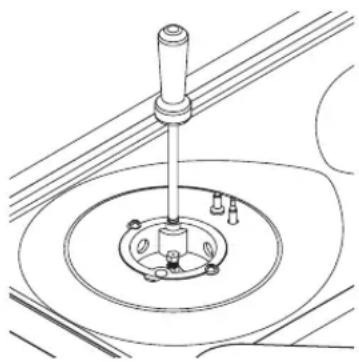

To Adjust the Gas Rate
With the aid of a thin bladed screwdriver, completely tighten down the bypass adjustment screw, which is located down the centre of the gas tap control shaft or on the gas tap body. See further adjustments in the next section.
Upon completion, stick the replacement rating plate sticker on the underside of the hob.

Minimum Setting or Turn Down
This unit has been set at the factory for NG but can be checked after the correct pressure has been reached. To adjust the minimum setting you will need a ∅ 2.5mm x 45mm screwdriver.
- Ignite the burner and set the control to its minimum position.
- Remove the control.
3. FOR NG (G20 G25)
Rotate the turn down screw slowly until a minimum regular flame is achieved. (The flame will diminish when the screw is turned clockwise and increase when turned anti-clockwise.)
FOR LP Gas (G30 G31)
Rotate the turn down screw clockwise until it comes to a stop, this is the fixed turn down position for LP Gas.
- Replace the control.
- When the setting is right check regulation by quickly rotating the control from the maximum to the minimum delivery position. The flame must not go out and remain stable throughout the range.

Burner Configuration
| Gas Category | LPG (Supplied in accessory pack) NG (Fitted on unit) | ||
| G30 G31 G20 | |||
| GB: II 2H/3 + 28 - 30 mbar | 28 - 30/37 mbar 20 mbar | ||
| Large Burner (Front Left) | |||
| Injector dia. (mm) 0.85 | 0.85 1.15 | ||
| Nominal Rating (kw) | 3 | 3 | 3 |
| Min. Rating (KW) | 1 | 1 | 1 |
| Consumption in 1 h(at 15°C and 1013 mbar press) | 218.13 gr/h | 214.28 gr/h | 285.7 lt/h |
| Small Burner (Front Right) | |||
| Injector dia. (mm) 0.50 | 0.50 0.72 | ||
| Nominal Rating (kw) | 1 | 1 | 1 |
| Min. Rating (KW) | 0.3 | 0.3 | 0.3 |
| Consumption in 1 h(at 15°C and 1013 mbar press) | 72.71 gr/h | 71.42 gr/h | 95.24 lt/h |
| Medium Burner (Rear Left And Right) | |||
| Injector dia. (mm) | 65 | 65 | 97 |
| Nominal Rating (kw) | 1.75 1.75 1.75 | ||
| Min. Rating (KW) | 0.44 0.44 0.44 | ||
| Consumption in 1 h(at 15°C and 1013 mbar press) | 127.25 gr/h | 125 gr/h | 166.66 lt/h |

Gas Category
| I3+(28-30/37) | BE, FR, IT, LU, IE, GB, GR, PT, ES, CY, CZ, LT, SK, CH, SI |
| I38/P(30) | LU, NL, DK, FI, SE, CY, CZ, EE, LT, MT, SK, SI, BG, IS, NO, TR, HR, RO, IT, HU |
| I38/P(37) | PL |
| I38/P(50) | AT, DE, CH, SK |
| I2Lw | PL |
| I2Ls | PL |
| I2E+ | BE, FR |
| I2H(20) | FR, IT, BE, NL, DK, IE, GB, GR, ES, PT, AT, FI, SE CZ, EE, HU, LV, LT, SK, SI, IS, NO, CH, TR, BG, HR and RO. |
| I2E(20) | DE, LU, PL |
The product is factory set for Natural Gas. Refer to the Installation Instructions for conversion to LP Gas.

Safety Warnings
Important!
- Please make this information available to the person responsible for installing the product.
- Read these instructions carefully before installing or using this product.
Installation
- This appliance shall be installed in accordance with the regulations in force and only used in a well ventilated space. Read the instructions before installing or using this appliance.
- The adjustment conditions for this product are stated on the data plate.
- This product is not connected to a combustion products evacuation device. It shall be installed and connected in accordance with current installation regulations. Particular attention shall be given to the relevant requirements regarding ventilation.
Caution!
- In order to avoid hazard this unit must be installed according to these instructions.
- Please follow installation information carefully. If in doubt consult your local building regulations, local gas authority standards and electrical regulations.
- In your own interest and that of safety, it is law that all gas appliances be installed by competent persons. (Gas Safe registered installers in the United Kingdom) who undertake to work to safe standards.
- Failure to install the product correctly could invalidate any warranty or liability claims. This appliance must be installed in accordance with local regulations and standards.
- In the United Kingdom, this hob must be installed in accordance with all relevant British Standards/Codes of Practice, in particular the latest editions of BS5440 part 2, BS6172 and BS6891. The Gas Safety (Installation and Use) Regulations. The Relevant Building/ IEE Regulations.
Operation and Maintenance
Hot Surface Hazard
- This appliance becomes hot during use. Do not touch the hob components, burners, trivets/pan supports or the base when hot. Before cleaning, turn the burners off and make sure the whole hob is cool. Failure to do so could result in burns and scalds.
Explosion Hazard
- Do not store flammable materials such as gasoline near the hob.
- No combustible material or products should be placed on or near this product at any time.
- Do not spray aerosols in the vicinity of this product while it is in operation.
- Failure to do so may result in death or electrical shock.
Important Safety Precautions
- CAUTION: This appliance is for cooking purposes only. It must not be used for other purposes, e.g. room heating.
- This appliance is not intended for use by persons (including children) with reduced physical, sensory or mental capabilities, or lack of experience and knowledge, unless they have been given supervision or instruction concerning the use of the appliance by a person responsible for their safety. Children should be supervised to ensure that they do not play with the appliance.
- This appliance is connected to the electrical supply by a BS 1363 mains plug. This plug provides isolation from the electricity supply. The plug must remain accessible or be connected to a socket with an all-pole disconnection switch provided in the fixed wiring and easily accessible. Never plug this unit in using an extension lead.
- Do not stand or place heavy objects on this appliance.
- This hob is not intended to be operated by means of an external timer or separate remote control system.
- Do not use an asbestos mat or decorative covers between the flame and the saucepan as this may cause serious damage to your hob.
- Do not place aluminium foil or plastic dishes on the hob burners.
- Do not use large saucepans or frying pans that overlap the hob as this can deflect heat onto your worktop and damage the surface.
- Do not let large saucepans, frying pans or woks push any other pans aside. This could make them unstable or deflect heat onto your worktop and damage the surface.
- Do not use a steam cleaner for cleaning this product.
- Saucepan handles may be hot to touch. Ensure saucepan handles do not overhang other gas burners that are on. Keep handles out of the reach of children.
- If the mains cable is damaged, it must only be replaced by an authorised person to avoid a hazard. Ensure that the electrical connection plug/switch is accessible after installation.
- CAUTION: The use of a gas cooking appliance results in the production of heat, moisture and products of combustion in the room in which it is installed. Ensure that the kitchen is well ventilated especially when the appliance is in use: keep natural ventilation holes open or install a mechanical ventilation device (mechanical extractor hood). Prolonged intensive use of the appliance may call for additional ventilation, e.g. opening of a window, or more effective ventilation, e.g. increasing the level of mechanical ventilation where present.
If you require a replacement for any of the items listed below, please quote their corresponding part numbers:
Left 37002036
Pan Support
Right 37002037
LPG Nozzle Installation Guide 52007667
LPG Replacement Rating Plate Sticker 20628175
Fixing Plate 37001970
Screw 37002652
∅ 100 37001482
LPG Nozzle
∅ 75 37001483
∅ 55 37001484
Seal 62000705
100mm Burner Rings 37001476
75mm Burner Rings 37001477
55mm Burner Rings 37001478
100mm Burner Cap 37001479
75mm Burner Cap 37001480
55mm Burner Cap 37001481
Visit Partmaster.co.uk today for the easiest way to buy electrical spares and accessories. With over 1 million spares and accessories available we can deliver direct
to your door the very next day. Visit www.partmaster.co.uk or call 0844 800 3456 (UK customers only) Calls charged at National Rate.
This symbol on the product or in the instructions means that your electrical and electronic equipment should be disposed at the end of its life separately from your household waste. There are separate collection systems for recycling in the EU.
For more information, please contact the local authority or your retailer where you purchased the product.
DSG Retail Ltd. • Maylands Avenue • Hemel Hempstead
Herts • HP2 7TG • England
(P.N.: 52036601-V2)
- CONTENTS
- UNPACKING
- PRODUCT OVERVIEW
- BEFORE USING YOUR NEW HOB
- LIGHTING THE HOB
- FLAME FAILURE SAFETY FEATURE
- IF THE BURNER DOES NOT LIGHT
- IF THE FLAME IS IRREGULAR
- ELECTRICITY FAILURE
- COOKWARE GUIDELINES
- DO NOT USE COOKING VESSELS ON THE HOB THAT OVERLAP ITS EDGES
- CLEANING AND MAINTENANCE
- CLEANING THE GAS HOB
- BURNER PARTS AND PAN SUPPORTS
- REPLACING THE BURNERS
- CHECK THAT
- HOB CONTROLS
- HINTS AND TIPS
- INSTALLATION
- WIRING
- PROVISION FOR VENTILATION
- LOCATION
- WHEN THE HOB IS FIRST INSTALLED
- GAS CONNECTION
- CUT OUT DIMENSIONS
- OVERALL DIMENSIONS
- FITTING THE HOB INTO THE WORKTOP
- CHECK THE HOB AFTER INSTALLATION & BEFORE USING
- PRESSURE TESTING
- CONVERSION FROM NG TO LPG OR FROM LPG TO NG
- NATURAL GAS
- LP GAS
- METHOD
- TO ADJUST THE GAS RATE
- MINIMUM SETTING OR TURN DOWN
- FOR NG (G20 G25)
- FOR LP GAS (G30 G31)
- BURNER CONFIGURATION
- GAS CATEGORY
- SAFETY WARNINGS
- IMPORTANT
- CAUTION
- OPERATION AND MAINTENANCE
- HOT SURFACE HAZARD
- EXPLOSION HAZARD
- IMPORTANT SAFETY PRECAUTIONS
Brand : Logik
Model : LGHOBX10
Category : Cooker