MGH61WHFF - Stove MATSUI - Free user manual and instructions
Find the device manual for free MGH61WHFF MATSUI in PDF.

| Product Type | Gas Hob |
| Brand | Matsui |
| Model | MGH61WHFF |
| Number of Burners | 4 |
| Dimensions (W x D x H) | 590 x 520 x 50 mm |
| Weight | 8.5 kg |
| Power Supply | Natural Gas (G20) or LPG (G30/G31) |
| Gas Connection | 1/2" BSP male thread |
| Nominal Heat Input | 3.0 kW per burner (variable) |
| Functions | Flame failure safety device, automatic ignition, simmer capability |
| Control Type | 6 mm push-fit knobs with flame indicator |
| Surface Material | Stainless steel / glass (depending on variant) |
| Pan Support Material | Enamelled cast iron |
| Cleaning Instructions | Wipe with damp cloth and mild detergent; avoid abrasive cleaners |
| Safety Features | Thermocouple flame failure device, anti-tilt brackets |
| Spare Parts Available | Burner caps, burner rings, knobs, thermocouple, pan supports |
| Repairability Index | 8.5 / 10 (based on access to spare parts and service) |
| Installation Type | Built-in or freestanding (with suitable cut-out) |
| Energy Efficiency Class | Class A |
| Warranty | 2 years manufacturer warranty |
Frequently Asked Questions - MGH61WHFF MATSUI
User questions about MGH61WHFF MATSUI
0 question about this device. Answer the ones you know or ask your own.
Ask a new question about this device
Download the instructions for your Stove in PDF format for free! Find your manual MGH61WHFF - MATSUI and take your electronic device back in hand. On this page are published all the documents necessary for the use of your device. MGH61WHFF by MATSUI.
USER MANUAL MGH61WHFF MATSUI
MGHSDMF D3.gxd 27/6/06 10:12 Page 1
user guide
Gas Hob
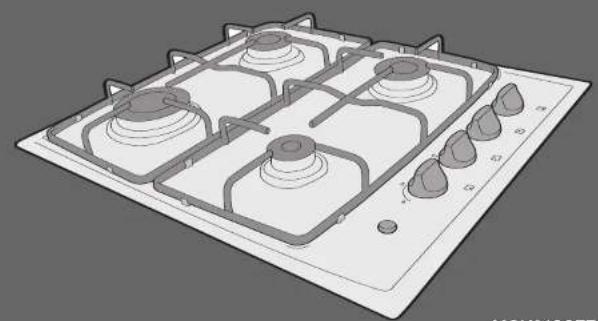
natural_image
3D rendering of a gas stove with four burners and control knobs (no text or symbols)MGH61SSFF MGH61WHFFM
MATSUI
MGHSDMF D3.gxd 27/6/06 10:12 Page 2
contents
getting to know your gas hob 3
important safety notes 4
control panel 6
instructions for use 7
hints and tips 9
installation guide 11
specifications 16
getting to know your gas hob
Thank you for choosing this Matsui gas hob. We hope the following information will help you to familiarise yourself with the features of the hob and help you use it successfully and safely.
Please read this user guide before using the hob and keep it for future reference.
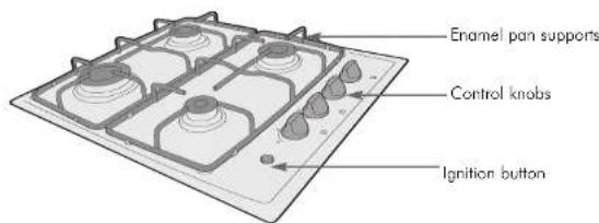
text_image
Enamel pan supports Control knobs Ignition buttonSupplied with the gas hob
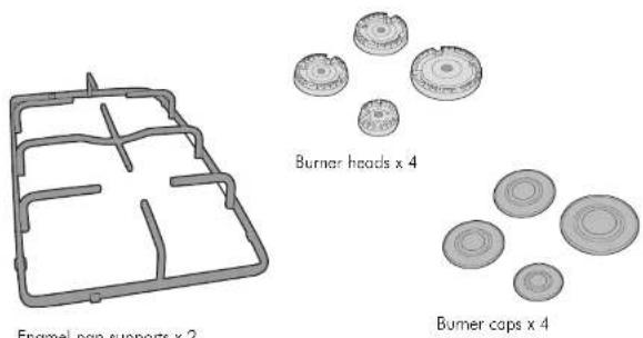
text_image
Enamel pan supports x 2 Burner heads x 4 Burner caps x 4LPG injectors x 4 (not shown) for use with LPG only.
important safety notes important safety n
We have included this section for your safety. Please read this information carefully before using your gas hob.
WARNING:
- The connection to the gas supply must be carried out by a qualified gas fitter, in accordance with local and national safety regulations.
- The manufacturer cannot be held responsible for damage caused by incorrect installation or connection.
- Repairs to the gas and electrical components of this hob must only be carried out by a suitably qualified person. Repairs by unauthorised people could be dangerous. On no account open the outer casing of the hob.
Safety notes
- Keep this user guide in a safe place, for reference.
- This hob is for domestic use only, and is not intended for commercial use.
- Do not let children access the hob or the controls.
- Do not use the hob to heat up a room. The high temperature could cause inflammable objects nearby to catch fire.
- Do not use plastic or aluminium foil containers. These melt at higher temperatures and could damage the surface. This is a potential fire hazard.
- In the event of damage or a defect, switch off the hob immediately. Turn off the gas supply tap and disconnect completely from the electricity supply, then contact your local service centre.
- Do not use the hob as a resting place for anything else, if the hob was still hot the article could begin to melt or catch fire.
- Remove splashes of food especially fat from the hob, as these are potential fire hazards.
-
Never leave the hob unattended when cooking with oils or fats as they can overheat and catch fire.
-
Spray canisters, aerosols and other inflammable substances should not be stored in a drawer under the hob, if there is no shelf separating the drawer from the hob.
- Ensure the room in which the hob is installed has sufficient ventilation. In a small kitchen it may be advisable to keep the door open if using the hob for an extended period of time.
- The hob must not be set up or operated in the open air.
- Make sure all the components of the gas burners have been correctly assembled before switching on.
- The use of a gas cooking appliance results in the production of heat and moisture in the room in which it has been installed. Ensure that the kitchen is well ventilated: keep natural ventilation holes open or install a mechanical ventilation device (extractor hood). Prolonged extensive use of the appliance may call for additional ventilation, for example opening of a window or increasing the level of mechanical ventilation
- If the burner flames accidentally go out, turn off the burner and do not try to re-ignite for at least 60 seconds.
- The burners in this hob are fitted with a flame sensing device that will shut of the gas it the flame is extinguished due to it being blown out or if a pan has boiled over. This safety device will require you to hold the gas knob down for a few seconds after the flame has ignited. You should not have to hold the knob down for more than 10 seconds. If during cooking you find the flame has become extinguished, turn off the gas with the control knob, wait for 60 seconds before relighting the burner.
MGH60NH D3.qxd 27/5/06 10:12 Page 6
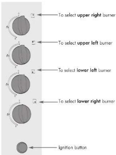
control panel
Your built-in gas hob has four burners. Each knob has a symbol above it, which indicates which burner it controls. The control knobs are used to switch on the burner and regulate the strength of the flame.
Functions
text_image
To select upper right burner To select upper left burner To select lower left burner To select lower right burner Ignition button6
instructions for use
Using the burners
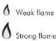
1 The control knob for the burner required must be pressed in. Turn it anti-clockwise towards the large flame symbol to switch on while pressing the ignition button.
2 Make sure the flame ignites within a few seconds of opening the gas supply.
Note: If the flame goes out turn the burner off, wait 60 seconds and then repeat the procedure, keeping the ignition button pressed in for a few extra seconds.
3 With the knob no longer pressed in, you can continue turning it towards the small flame symbol, depending on the setting you want to cook with.
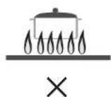
4 Control the flame so that it does not spread out beyond the side of the pan, as the outer part of the flame is much hotter than the centre, the tips of the flame should stay beneath the pan base.
Turning a burner off
1 Turn the knob clockwise until the '0' position is reached. This stops the flow of gas and the flame will go out.
2 Remember: Turn anti-clockwise to switch on, turn clockwise to switch off. The control knob cannot be turned anti-clockwise from the small flame symbol to the '0' position.
temperature setting guide
| Gentle simmering, slow warming, reheating and rapid simmering | |
| Boiling, sauté and searing – maximum heat |
7
MGHSDMF D3.gxd 27/6/06 10:12 Page 8
hints and tips
Cookware
Pans
- A simple rule is that large pans are used on the large burners and small pans on the small burners.
- Wide, shallow pans are preferable to narrow, tall ones. They heat up more quickly as there is room for more flame under the base.
- For safety and stability, use pans with a minimum base diameter of 12cm for the small burner and 14cm for the medium burners, and 22cm for the large burner.
- Pan bases do not need to be even for cooking.
- Thick pan bases reduce the risk of food overheating in places, as heat is better distributed.
- Thin pan bases conduct heat to the food inside more quickly than thicker ones. However, as the heat is not evenly distributed over the pan base, there is a danger that food may heat up unevenly, so stir the food frequently.
Energy saving
- Using a lid will reduce cooking times.
- When liquid comes to the boil reduce the temperature setting.
- Choose cookware of the proper size, material and construction.
- Minimise the amount of liquid or fat to reduce cooking times.
- Select the proper temperature setting for the cooking task.
Cleaning tips
■ Under no circumstances should you use a steam-cleaning appliance to clean the hob.
- Do not use any share objects, which could cause damage to the hob or the burners.
- Never use abrasive cleaning materials.
- Do not let the ignitor in the burner get wet. If it gets wet it will not spark.
- After cleaning the hob it must be thoroughly dried with a soft cloth to prevent a build up of lime scale deposits.
8
hints and tips
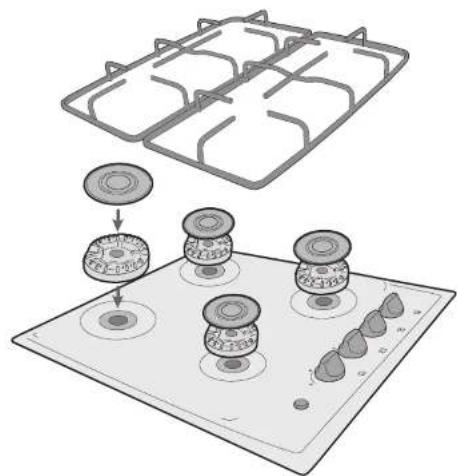
Cleaning the burners
- The removable parts of the gas burner assembly can be washed in a mild solution of water and washing-up liquid. Wipe dry and re-assemble in the correct order. (See diagram below).
- The surface of the burner cover will gradually lose its gloss finish with time. This is quite normal and will not effect the efficiency of the hob.
IMPORTANT
The locating lugs must fit exactly into the notches.
natural_image
Illustration of a kitchen appliance with three panes and a stove base, showing a step-down view (no text or symbols)9
MGHSOWH D3.gxd 27/6/06 10:12 Page 10
installation guide
Safety
- This hob is to be installed in accordance with current regulations and should only be used in a well-ventilated room.
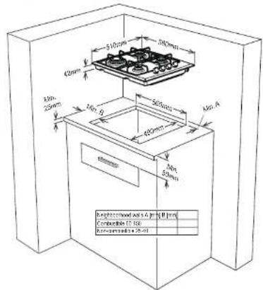
Fitting the hob into a work surface
1 The hob can be fitted into any work surface provided it is heat resistant up to at least 90°C.
2 Create an opening with the dimensions shown in the picture below. Ensure there is at least 6cm between the rear edge of the hob and any adjacent rear wall.
text_image
510mm 380mm 420mm 480mm 560mm 400mm 480mm 480mm 500mm 480mm Background owned at 4 m² (10 mm) Conventional DC 100 Reconventional DC 1003 Apply the self-adhesive seal to each edge of the opening and carefully fit the hob into the opening.
There must be a distance of at least 750mm between the hob and any top wall cupboard. In case there is an extractor hood above the hob, the distance between the hob and the extractor hood must be 650mm.
10
installation guide
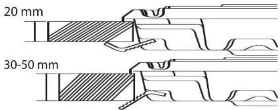
4 Secure the hob in place by tightening the clamps around its perimeter edge, as the picture below shows. The clamps can be fitted in one of two ways, to accommodate the thickness of the worktop. If the worktop is too thick to accommodate the clamps, cut slots within the thickness of the worktop to reduce its thickness.
text_image
20 mm 30-50 mm5 If there is any self-adhesive seal protruding from the edge of the hob, trim it off, being careful not to scratch the worktop. 6 If the hob is being fitted over a cupboard or drawer unit which has no top panel, a top panel must be fitted. This panel will form a separation between the contents of the cupboard or drawer and the underside of the hob. The panel should be removable, to allow for access to the underside of the hob, and can be fitted at least 5cm from the underside of the hob.
installation guide
Making an electrical connection
1 Make sure the voltage of your power supply is 230V. The power supply required by the hob (230v) is specified on its rating plate.
2 Connect the hob to its power supply. If the power supply cable needs to be replaced, the new cable must not be less than 0.75mm2 (3 x 0.75 cable). Use H05V2V2-F cable or similar which has a maximum temperature resistance of 90°C.
Making a gas connection
IMPORTANT
The gas supply to the hob must be connected by a qualified gas fitter. The hob is factory set for connection to a Natural Gas (NG) supply.
The hob can be adjusted for use with Liquified Petroleum Gas (LPG). These adjustments must be carried out by a qualified gas fitter. LPG injectors are included with the hob for this purpose. The valves must also be adjusted.
The hob must be installed in accordance with all relevant local building regulations, gas authority codes and codes of practice.
In the UK BS5440 part 2, BS6172 and BS6891 and the Gas Safety (installation and use) regulations 1998 must be adhered to. The hob must be fitted by a qualified and CORGI registered gas fitter.
1 The hob is supplied with a 1/2 BSP female connection. It should be connected to the gas supply by use of the 1/2 BSP restrictor elbow, seal and copper pipe and have an isolation valve fitted in an easily accessible position. It is recommended that connection to the gas supply is made using a rigid 15mm copper pipe. Alternatively a flexible pipe made specifically for the purpose of connecting gas appliances can be used. The pipe's length should not exceed 1.5 metres. The pipe should be fitted so that it does not come into contact with any moving parts or combustible items.
installation guide
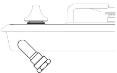
natural_image
Technical line drawing of a kitchen sink with a handle and bulb (no text or symbols)2 Once the hob is connected, open the valve on the gas supply pipe. Use a leak detection fluid to check each connection in the gas supply. The presence of bubbles will indicate a leak.
3 If no leaks are apparent, turn on one bumper at a time and check the flame on each. The flames should be clear blue, with no yellow tip and should not extinguish when changing from maximum to minimum flow.
If the hob is to be adapted for LPG, proceed as follows:
1 Isolate the appliance from the electricity and gas supplies.
2 Remove the pan supports and burner assemblies.
3 Replace the injectors with the alternative LPG injectors supplied.
4 Adjust the valves.
4a Make sure the appliance is isolated from the electricity.
4b Open the gas feed slightly.
4c Ignite the burners and leave them on at the lowest setting.
4d Remove the knobs and rubber seals to access the screws undemeath.
4e Adjust the flame to a length of at least 4 mm by tightening (from NG to LPG) or loosening the screw (from LPG to NG) with a screwdriver. Make sure the flame does not die out.
4f Repeat the steps above for each valve.
4g Replace the knobs and rubber seals when complete.
5 Use the appropriate thread sealant and check for gas soundness.
6 Mark the rating plate to amend the Gas type details.
troubleshooting
Below are solutions to minor problems which may occur;
Q. A burner does not ignite, what do I do?
A. Check whether the burner is correctly assembled and whether the mains gas supply tap is turned on. Also check that the burner is dry and clean, the flame slits should be clean and un-blocked. If the mains fuse has blown, call an electrician; the gas can be lit with a match if there is a temporary power cut.
Q. What do I do if the gas flame goes out after being lit?
A. Make sure the gas control is turned back to 0.
Check whether the burner cover is correctly assembled.
Q. What do I do if the ignitor on the burner does not spark?
A. Check whether food deposits have lodged themselves between the ignitor and the burner cover. Carefully remove any soiling. Do not let the ignitor get wet.
Q. What do I do if the flame suddenly looks different?
A. Check whether the burner is correctly assembled.
specifications
Model
MGH61SSFF/MGH61WHFF
MGH60SS/MGH60WH
Rated Voltage (V) 230
Rated 'Frequency (Hz) 50
Gas Type NG or LPG (Default set to NG)
Net Weight (kg) 6.7
Product Dimensions (cm)
External Width 58
External Depth 51
Product Dimensions (cm)
Internal Width 55
Internal Depth 48
MGHSOWH D3.gxd 27/6/06 10:12 Page 18
Gas Category LGP LGP NG NG
| G30 G31 G20 G25 | |||
| GB. II 2H/3 I 2B-30 mbar | 28-30/37 mbar 20 mbar 25 mbar |
LARGE BURNER
| Injector diam. (%mm) 85 85 115 125 | ||||
| Nominal Rating (kw) 3 3 3 | 3 | |||
| Min. Rating (KW) | 0.85 0.85 0.7 0.82 | |||
| Consumption in 1h | 218.13 gr/h | 214.28 gr/h | ||
| Consumption in 1 h(at 15°C and 1013 mbar press) | 285.7 lt/h | 332.2 lt/h | ||
SMALL BURNER
| Injector diam. (%mm) 50 50 72 72 | ||||
| Nominal Rating (kw) 1 1 1 | 1 | |||
| Min. Rating (KW) | 0.4 | 0.4 | 0.3 | 0.3 |
| Consumption in 1h | 72.71 gr/h | 71.42 gr/h | ||
| Consumption in 1 h(at 15°C and 1013 mbar-press) | 95.74 l/h | 110.74 l/h | ||
MEDIUM BURNER
| Injector diam. (%mm) 65 65 97 94 | ||||
| Nominal Rating (kw) 1.75 | 1.75 1.75 1.75 | |||
| Min. Rating (KW) | 0.65 | 0.65 | 0.495 | 0.495 |
| Consumption in 1h | 127.25 gr/h | 125 gr/h | ||
| Consumption in 1 h(at 15°C and 1013 mbar press) | 166.66 lt/h | 193.79 lt/h | ||
MSH60WH D3.gxd 27/6/06 10:12 Page 18


natural_image
Solid gray rectangular shape with no text, symbols, or discernible features.
natural_image
Solid gray rectangular shape with no text, symbols, or discernible features.


19

MGHS049 D3.gxd 27/6/06 10:12 Page 20

Partmaster
.co.uk
Visit Partmaster.co.uk today for the easiest way to buy electrical spares and accessories.
With over 50,000 products in stock we can deliver direct to your door the very next day.
Visit www.partmaster.co.uk
or call 0844 800 3496
(UK customers only)
Cells charged at National Rate.

This symbol on the product or in the instructions means that your electrical and electronic equipment should be disposed at the end of its life separately from your household waste. There are separate collection systems for recycling in the EU. For more information, please contact the local authority or your retailer where you purchased the product.
012008R000
52014850