
78MCICRG5 - Hot plate Infiniton - Free user manual and instructions
Find the device manual for free 78MCICRG5 Infiniton in PDF.

| Product Type | Electric Ceramic Hob |
| Brand | Infiniton |
| Model | 78MCICRG5 |
| Number of Cooking Zones | 4 |
| Cooking Zone Types | Radiant (2x 1400W, 1x 1800W, 1x 1200W) |
| Control Type | Touch control with digital display |
| Installation Type | Built-in |
| Dimensions (W x D x H) | 590 x 520 x 45 mm |
| Cutout Dimensions | 560 x 490 mm |
| Weight | 10.5 kg |
| Power Supply | 220-240 V ~ 50/60 Hz |
| Total Power Consumption | 7000 W (approx.) |
| Main Functions | 9 power levels, timer, child lock, auto shut-off, residual heat indicator |
| Cleaning and Maintenance | Wipe with damp cloth; use ceramic hob cleaner for stubborn stains |
| Safety Features | Child lock, overheat protection, automatic shut-off, residual heat indicator |
| Spare Parts and Repairability | Available through authorized service centers; control board and heating elements replaceable |
| Warranty | 2 years (standard) |
| Energy Efficiency Class | A (per EU regulation) |
| Included Accessories | Installation screws, power cord, user manual |
Frequently Asked Questions - 78MCICRG5 Infiniton
User questions about 78MCICRG5 Infiniton
0 question about this device. Answer the ones you know or ask your own.
Ask a new question about this device
Download the instructions for your Hot plate in PDF format for free! Find your manual 78MCICRG5 - Infiniton and take your electronic device back in hand. On this page are published all the documents necessary for the use of your device. 78MCICRG5 by Infiniton.
USER MANUAL 78MCICRG5 Infiniton
Instruction Manual ENGLISH
This appliance can be used by children aged from 8 years and above and persons with reduced physical, sensory or mental capabilities or lack of experience and knowledge if they have been given supervision or instruction concerning use of the appliance in a safe way and understand the hazards involved. Children shall not play with the appliance. Cleaning and user maintenance shall not be made by children without supervision.
Congratulations on choosing appliance, which you will find is dependable and easy to use. We recommend that you read this manual for best performance and to extend the life of your appliance. Thank you.
Close-up View

75CRGASG56
76IXGASG50
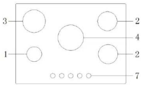
77MCIXG
78MCICRG5

- Auxiliary Gas Burners
- Semi-rapid burner
- Rapid burner
- Triple ring burner
- Ignitor for Gas Burners (only on certain models)
- Safety Device (only on certain models) - Activates if the flame accidentally goes out (spills, drafts, etc.), interrupting the delivery of gas to the burner.
- Control Knobs for Gas Burners
NOTICE
The stainless steel grease pan and the cast-iron grill, located in the burner and grate packing box, must be installed, respectively, below and above the electric heating element so that tile element is enclosed between the two.
The product complies with COMMISSION REGULATION (EU) No 66/2014. In terms of the calculation formula, please refers to the directive. The testing method is performed based on the directive EN 30-2-1:1998+A1:2003+A2:2005 (If it is regulated by the government, the relevant testing method would be done accordingly). Please refer to the product label for the detail concerning the testing figures
In order to reduce the unnecessary waste and control the impact by the combustion, please save the energy and adjust the gas consumption according to the necessity.
The specialized technician should avoid any damage and deformation of every component when he repairs the product. The change of relevant components must be done by the authorized technician under the guidelines by the manufacturers and distributors. This is a necessary way to avoid the working efficiency impacted.
How To Use Your Appliance
The position of the corresponding gas burner or electric hot plate (if present) is indicated on each control knob.
Gas Burners
The burners differ in size and power. Choose the most appropriate one for the diameter of the cookware being used.
The burner can be regulated with the corresponding control knob by using one of tile following settings:
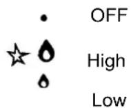
To turn on one of the burners, place a lighted match or lighter near the burner, press the knob all the way in and turn in the counter-clockwise direction to the "High" setting.
On those models fitted with a safety device (F), the knob must be pressed in for about 6 seconds, until the device that keeps the flame lighted warms up.
On those models fitted with an ignitor (D), the "E" ignition button, identified by the ☆ symbol, must
first be pressed and then the corresponding knob pushed all the way in and turned in the counter-clockwise direction to the "High" setting.
Some models are equipped with an ignition switch incorporated into the control knob. If this is the case, the ignitor (D) is present, but not the "E" switch (the ☆ symbol is located near each knob).
To light a burner, simply press the corresponding knob all the way in and, then, turn it in the counter-clockwise direction to the High setting, keeping it pressed in until the burner lights.
Caution: If the burner accidentally goes out, turn off the gas with the control knob and try to light it again
after waiting at least 1 minute.
To turn off a burner, turn the knob in the clockwise direction until it stops (it should be on the "." setting).
Electric Hot Plates (only on certain models)
The hot plates vary in diameter and power: "normal" and "fast". The latter can be identified by a red boss in the center of the hot plate itself.
The hot plate can be regulated by turning the corresponding knob in the clockwise or counter-clockwise direction to any one of the 6 different settings:
0 OFF
1 Low
2-5 Medium
6 High
The section entitled, "Practical Cooking Advise", provides information on the recommended settings for various types of food or cooking processes.
When the knob is on any of the settings other than "OFF", the "H" operating light comes on. Cooktop Broiler (only on certain models)
The broiler can be regulated by turning the corresponding knob in the clockwise or counter-clockwise direction to any of the 12 possible settings:
0 OFF
1 Low
2-11 Medium
12 High
When the knob is on any of the settings other than "OFF", the "H" operating light comes on.
How to Keep Your Cooktop in Shape
Before cleaning or performing maintenance on your appliance, disconnect it from the electrical power supply.
To extend the life of the cooktop, it is absolutely indispensable that it be cleaned carefully and thoroughly on a frequent basis, keeping in mind the following:
- The enameled parts and the glass top, if present, must be washed with warm water without using abrasive powders or corrosive substances which could ruin them;
- The removable parts of the burners should be washed frequently with warm water and soap, making sure to remove caked-on substances;
- On cooktops with automatic ignition, the end of the electronic ignition device must be cleaned carefully and frequently, making sure that the gas holes are not clogged;
- The electric hobs should be cleaned using a damp cloth and then rubbed with oil while still warm;
- Stainless steel can be stained if it remains in contact with highly calcareous water or aggressive detergents (containing phosphorous) for an extended period of time, it is recommended that these parts be rinsed thoroughly with water and then dried well, It is also a good idea to clean up any spills;
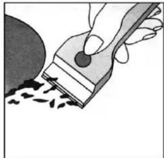
- Before using the ceramic glass module, the surface must be cleaned, using a damp cloth to remove dust or food residues. The ceramic glass surface should be cleaned regularly with a solution of warm water and a non-abrasive detergent, Periodically, special products will need to be used to clean the surface. First, remove all food buildup or grease with a cleaning scraper, e.g.
CERA (not supplied) (Fig. 1).
Clean the cooking surface when it is still warm with a suitable cleaning product and paper towels. Then rub with a damp cloth and dry. Aluminum foil, plastic items, objects made of synthetic material, sugar or
foods with a high sugar content that have melted onto the surface must be removed immediatley with a scraper while the cooking surface is still hot. Special cleaning products for ceramic glass surfaces form a transparent protective layer which fights dirty buildup. This also protects the surface from damage caused by food with a high sugar content. Do not use abrasive sponges or cleaning products under any circumstances. This holds
true for chemically aggressive cleaners, like oven sprays and stain removers (Fig.2);
natural_image
Illustration of a hand using a tool to brush or paint onto a surface, with no visible text or symbols.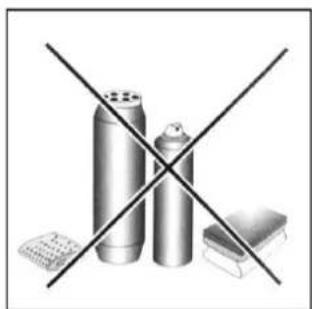
natural_image
Illustration of three spray cans crossed with a diagonal line, no text or symbols presentFig.1 Fig.2
- When cleaning the grill, it is recommended that you do so while it is still hot, using the handles provided to move it from the cooktop to the sink. To remove the pan beneath the grill, it is a good idea to wait until the heating element has cooled (roughly after 15 minutes)
Greasing the Gas Valves
Over time, the gas valves may stick or become difficult to turn. If this is the case, the must be cleaned on the inside and the regreased, i
N.B.: This procedure must be performed by a technician authorized by the manufacturer.
Practical Advice
Practical Advise on Using the Burners
For best performance, follow these general guidelines:
- Use the appropriate cookware for each burner (see table) in order to prevent the flame from reaching the sides of the pot or pan;
• Alwasy use cookware with a flat bottom and keep the lid on; - When the contents come to a boil, turn the knob to "Low".
| Burner | ∅ Cookware diameter (cm) |
| Fast (R) | 24 - 26 |
| Reduced Fast (RR) | 24 - 26 |
| Semi Fast (S) | 16 - 20 |
| Auxiliary (A) | 10- 14 |
| Semi-Fischburner (SP) | 16 - 20 |
| Triple Crown (TC) | 24 - 26 |
To identify the type of burner, refer to the designs in the section entitled, "Burner and Nozzle Specifications".
Practical Advice on Using the Half Fish-Kettle Burner
The two central burners, or Half Fish-Kettle burners, are elliptic in form and can be turned up to 90^ . This makes the cooktop more flexible in terms of how it can be used.
To turn the two central burners 90\~, proceed as follows:
• Make sure that the burners are cool;
- Lift the burner completely out of its housing;
- Replace it in its housing in the position desired;
- Make sure that the burners are positioned correctly before use.
In addition, the two cetnral burners can be used in tandem or speartely with cookware of different shapes and sizes:
• Double burner for a fish-kettle or oval cookware (Fig. A).
- Double burner for large cookware (diameter of 26-28cm) (Fig. C).
- Single burner for medium size cookware (diameter of 16-20 cm) (Fig. D).
- Double burner for a griddle or rectangular/square cookware with minimum dimensions of 28x28 cm (Fig.B)
Practical Advice on Using the Electric Hot Plates
In order to avoid heat loss and damage to the hot plate. use cookware with a flat bottom the diameter of which is not less than that of the hot plate.
| Setting | Normal or Fast Plate |
| 0 | OFF |
| 1 | Cooking vegetables, fish |
| 2 | Cooking potatoes (using steam) soups, chickpeas, beans. |
| 3 | Continuing the cooking of large quantities of food, minestrone |
| 4 | For roasting (average) |
| 5 | For roasting (above average) |
| 6 | For browning and reaching a boil in a short time. |
Practical Advise on Using the Broiler
Preheat the broiler by turning the knob to 12. Settings 1-8 are recommended for reheating food or for keeping it warm after it has been cooked. In general, cooling vegetables can cause stains which are difficult to remove.
| Food | Weight(kg) | Knob Setting | Preheating(min) | Cooking Time(mm) |
| Pork Chops | 0.5 | 12 | 5 | 15 |
| 10 | 20 | |||
| Steak | 0.6 | 12 | 5 | 10 |
| Sausages | 0.45 | 10 | 5 | 20 |
| Shish Kabobs(meat) | 0.4 | 12 | 5 | 14 |
| Hamburgers | 0.4 | 10 | 5 | 15 |
| Toasted Sandwiches | No.3 | 11 | 5 | 2 |
| Bread | 3 Slices | 11 | 5 | 3 |
| Aubergines | 3 Slices | 12 | 5 | 5-7 |
| Oven-roasted Tomatoes | No.4 | 12 | 5 | 10-15 |
For best performance, keep in mind the following:
- All types of casseroles can be used on the ceramic glass cooking surface. However, it is important that the bottom be perfectly flat. Casseroles with thicker bottoms distribute heat more evenly.

Use cookware the diameter of which is at least as large as the cooking area so that all of the heat produced by the heating element is used.
- Make sure that the bottom of tile pot is always dry and clean to insure good contact between the cookware and the cooking surface. This will also increase the life of the pots and of the ceramic glass surface as well.
- Do not use the same cookware that you use for gas burners because the concentrated heat they produce can deform the bottom of the pot. Therefore, you will not achieve best results when using these pots on the ceramic glass surface.
Notice: The glue used to seal the glass surface may leave traces on the appliance. We recommend that the module be cleaned with a non-abrasive cleaner before being used
the first time. During the first few hours of use, you may detect the smell of rubber; this will disappear after a short time.
Is there a problem?
It may occur that the cooktop does not function or does not function properly. Before calling customer service for assistance, lets see what can be done.
First of all, check to see that there are no interruptions in the gas and electrical supplies, and, in particular, that the gas valves for the mains are open.
The burner does not light or the flame is not uniform around the burner.
Check to make sure that:
• The gas holes on the burner are not clogged;
- All of the movable parts that make up the burner are mounted correctly;
• There are no draughts around the cooking surface.
The flame does not stay lighted on the model with the safety device.
Check to make sure that:
• You press the knob all the way in;
- You keep the knob pressed in long enough to activate the safety device.
- The gas holes are not clogged in the area corresponding to the safety device.
The burner does not remain on when set to "Low".
Check to make sure that:
• The gas holes are not clogged.
- There are no draughts near tire cooking surface.
- Tile minimum has been adjusted correctly (see the section entitled, "Minimum Regulation").
The cookware is not stable.
Check to make sure that:
• The bottom of the cookware is perfectly flat.
- The cookware is centered correctly on the burner or electric hot plate.
- The support grids have not been inverted.
If, despite all of these checks, the cooktop does not function properly and problem persists, call the nearest Merloni Elettrodomestici Customer Service Centre informing them of:
--Tile type of problem.
--The abbreviation used to identify the model (Mod.... )as indicated on tile warranty.
Nover call upon technicians not authorized by the manufacturer, and refuse to accept spare parts that are not original.
Installation Instructions for built-in
The following instructions are directed at the qualified installer so that the installation and maintenance procedures may be followed in the most professional and expert manner possible. Important: Unplug the electrical connection before performing any maintenance or regulation upkeep work.
Positioning for gas hob
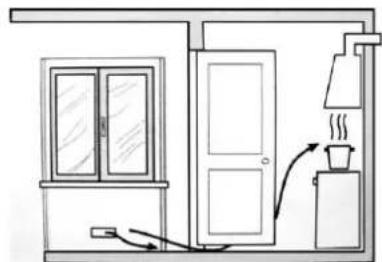
Important: this unit may be installed and used only in permanently ventilated rooms according to the British Stancards Codes Of Practice: B.S. 6172 / B.S. 5440, Par. 2 and B.S. 6891 Current Editions. The following requirements must be observed:
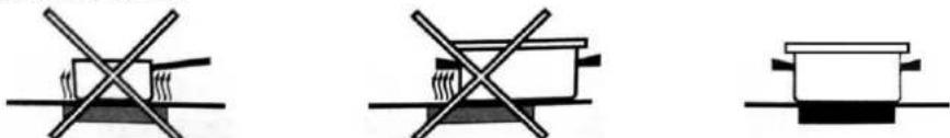
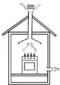
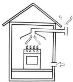
a) The room must be fitted with a ventilation system which vents smoke and gases from combustion to the outside.
This must be done by means of a hood or electric ventilator that turns on automatically each time the hood is operated.
natural_image
Simple line drawing of a house interior with a stove and roof, no text or symbols present.In a chimney stack or branched flue. Directiy to the Outside (exclusively for cooking appliances)
natural_image
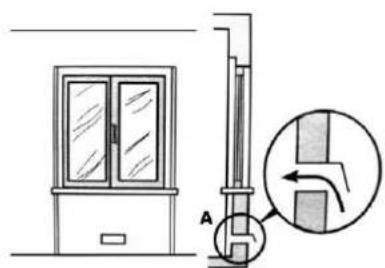
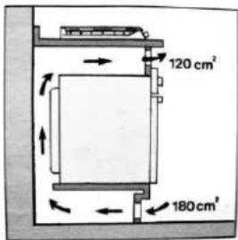
Simple line drawing of a house with a stove and steam rising from the chimney (no text or symbols)b) The room must also allow for the influx of the air needed for proper combustion. The flow of air for combustion purposes must, not be less than 2 m^3/h per kW of installed capacity. The supply of said air can be effected by means of direct influx from the outside through a duct with a inner cross section of at least 100 cm^2 which must not be able to be accidentally blocked. Those appliances which are not fitted
with a safety device to prevent the flame from accidentally going out must have a ventilation opening twice the size otherwise required, i.e. a minimum of 200 ~cm^2 (Fig. 3). Otherwise, the room can be vented indirectly through adjacent rooms fitted with ventilation ducts to the outside as described above, as long as the adjacent rooms are not shared areas, bedrooms or present the risk of fire (Fig. 4).
Detail A Adjacent Room Room to be Vented
natural_image
Technical diagram showing a door frame and a vertical structure with an inset view of a mechanical component (no text or symbols)Examples of ventilation holes for comburant air.
natural_image
Simple line drawing of a room with doors, a chimney, and a coffee cup (no text or symbols)Enlarging the ventilation slot between window and floor
Fig.3 Fig.4
c) Intensive and prolonged use of the appliance may necessitate supplemental ventilation, e.g. opening a Window or increasing the power of the air intake system (if present).
d) Liquidified petroleum gases are heavier than air and, as a result, settle downwards. Rooms in which LPG tanks are installed must be fitted with ventilation openings to the outside in order to allow the gas to escape in the event of a leak. Therefore, LPG tanks, whether empty or partially full, must not be installed or stored in rooms or spaces below ground level'(cellars, ect.). It is also a good idea to keep only the tank currently being used in the room, making sure that it is not near sources of heat (ovens, fireplaces, stoves, etc.) that could raise the internal temperature of the tank above 50°C.
Installation of built-in stove tops
The gas hobs are prepared with protection degree against excessive heating of type X, the appliance can therefore be installed next to cabinets, provided the height does not exceed that of the hob. For a correct installation of the cooking hob the following precautions must be followed:
a) The hob may be located in a kitchen, a kitonen/diner or bed sitting room, but not in a bathroom or shower room.
b) The furniture standing next to the unit, that is highe1 than the working boards, must be placed at least 110mm from the edge of the board.
c) The cabinets should be positioned next to the hood at a height of at least 420 mm (Fig. 5).
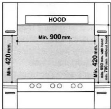
Fig.5
d) Should the hob be installed directly under a cupboard the letter should be at least 700mm (millimetres) from the worktop, as shown in Fig. C.
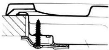
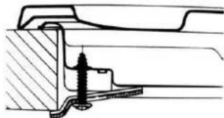
e) The dimensions of the room for the furniture must those indicated in the figures in the last two pages the cover. Fixing hooks are provided which allow place the hob plate on work tops that measure 20 to 40 ~mm in thickness (see Fig. 6). To obtain a of the hob plate it is advisable to use all the fixing supplied.
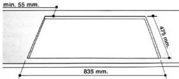
Fig.6
natural_image
Technical cross-sectional diagram of a mechanical assembly (no text or labels)H=30mm top
Hook position for Hook position for Hook position for

natural_image
Cross-sectional technical diagram of a mechanical assembly (no text or labels)H=40mm top
natural_image
Technical cross-section diagram of a mechanical assembly (no text or labels)H=20mm top
N.B: Use the hook contained in the "accessoires set"
f) In the event the cooktop is not installed above a built-in oven, a wood panel must be inserted as insulation. This panel must be placed at least 20 mm from the bottom of the cooktop itself.
Important: When installing the hob above a built-in oven, the oven should be placed on two wooden strips; in the case of a joining cabinet surface, remember to leave a space of at least 45 × 560 ~mm at the back.

natural_image
Simple line drawing of a cabinet or enclosure with two horizontal bars and a dashed-line floor, no text or symbols present.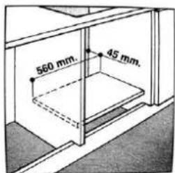
When installing on a built-in oven without forced ventilation, ensure that there are air inlets and outlets for ventilating the interior of the cabinet adequately.

Gas connection for gas hob
The Cooker should be connected to the gas-supply by a corgi registered installer. During installation of this product it is essential to fit an approved gas tap to isolate the supply from the appliance for the convenience of any subsequent removal or servicing. Connection of the appliance to the gas mains or liquid gas must be carried out according to the prescribed regulation in force, and only after it is ascertained that it is adaptable to the type of gas to be used. If not, follow the instructions indicated in the paragraph headed "Adaptation to different gas types". In
the case of connection to liquid gas, by tank, use pressure regulators that conform to the regulation in force. Important: For safety, for the correct regulation of gas use and long life of the appliance, ensure that the
gas pressure conforms to the indications given in table 1 "Nozzle and burner characteristics".
Connection to non-flexible tube
(copper or steel)
Connection to the gas source must be done in such a way as to not create any stress points at any part of the appliance.
The appliance is fitted with an adjustable, "L" shaped connector and a gasket for the attachment to the gas supply.
Should this connector have to be turned, the gasket must be replaced (supplied with the appliance).
The feeding connector of the gas to the appliance is threaded 1/2 gas male cylinder.
Connection to flexible steel tube
The gas feed connector to the appliance is a threaded, male 1/2" connector for round gas pipe. Only use pipes and sealing gaskets that that conform to the standards currently in force. The maximum length of the flexible pipes must not exceed 2000 mm. Once the connection has been
made, ensure that the flexible metal tube does not touch any moving parts and is not crushed.
Check the Seal
Once the appliance has been installed, make sure all the connections are properly sealed, using a soapy water solution. Never use a flame.
Electrical Connection
The cooktops fitted with a tripolar electrical supply cord are designed to be used with alternating current according to the indications on the rating plate located under the cooktop. The earthing wire can be identified by its yellow-green colour.
In the case of installation over a built-in electric oven, the electrical connections for the cooktop and oven should be independent, not only for safety purposes, but also to facilitate removal of one or both in the future.
Electrical Connection for Gas Cooktop
Fit the supply cord with a standard plug for the demand rate indicated on the rating plate or connect it directly to the electrical mains. In the latter case, a single pole switch must be placed between the appliance and the mains, with a minimum opening between the contacts of 3 mm in
compliance with current safety codes (the earthing wire must not be interrupted by the switch). The power supply cord must be positioned so that it does not reach a temperature in excess of 50\~C above room temperature at any point.
Before actual connection make sure that:
- The fuse and electrical system can withstand the load required by the appliance;
- That the electrical supply system is equipped with an efficient earth hook-up according to the norms and regulations prescribed by law;
- That the plug or switch are easily accessible.
Important: the wires in the mains lead are coloured in accordance with the following code:
Green & Yellow
- Earth
Blue
- Neutral
Brown
- Live
As the colours of the wires in the mains lead may not correspond with the coloured markings identifying the terminals in your plug, proceed as follows: Connect the Green & Yellow wire to terminal marked "E"
or ± or coloured Green or Green & Yellow.
Connect the Brown wire to the terminal marked "L" or coloured Red.
Connect the Blue wire to the terminal marked "N" or coloured Black.
Adapting the Cooktop for DifferentTypes of Gas
Table1 Burners and Nozzle Specifications
| G20 | G31 | G30-29 | G30-37 | G30-50 | ||||||
| Burner | Thermal power (kW) | Nozzle 1/100 (mm) | Thermal power kW | Nozzle 1/100 (mm) | Thermal power kW | Nozzle 1/100 (mm) | Thermal power kW | Nozzle 1/100 (mm) | Thermal power kW | Nozzle 1/100 (mm) |
| Auxiliary (Small) (A) | 1.0 | 0.78 | 1.0 | 0.5 | 1.0 | 0.5 | 1.0 | 0.47 | 1.0 | 0.45 |
| Semi rapid (Medium) | 1.8 | 1.03 | 1.8 | 0.67 | 1.8 | 0.67 | 1.8 | 0.62 | 1.8 | 0.59 |
| Rapid (R) | 3.0 | 1.28 | 3.0 | 0.85 | 3.0 | 0.85 | 3.0 | 0.81 | 3.0 | 0.77 |
| Triple Ring | 3.6 | 1.43 | 3.6 | 0.95 | 3.6 | 0.95 | 3.6 | 0.89 | 3.6 | 0.84 |

natural_image
Simple line drawing of a circular mechanical component with an arrow pointing to a central hole (no text or symbols)Replacement of burner nozzle: loosen the nozzle with a dedicated wrench(7). Fit the new nozzle, suitable for the required gas type (see table above for reference).
After you have converted the cooktop to another gas type, make sure you have placed a label containing that information on the appliance.
Adjustment of the reduced valve flow
Table2
| Burners | Flame | Converting the cooktop from LPG to natural gas | Converting the Cooktop from natural Gas to LPG |
| Regular burners | Full flame | Replace the burner Nozzle according To the guidelines in table 1 | Replace the burner Nozzle according to the guidelines in table 1 |
| Saving flame | Loosen the adjustmentSpindle (see fig.7 below )And adjust the flame | Loosen the adjustmentSpindle (see fig.7 below )And adjust the flame |
Valve adjustment
Valve adjustment should be done with the control knob set at Burner ON saving flame position. Remove the knob, and adjust the flame with a tiny screwdriver (see fig.7 below).

natural_image
Diagram of a mechanical assembly with a spring-loaded component inserted into a housing (no text or symbols)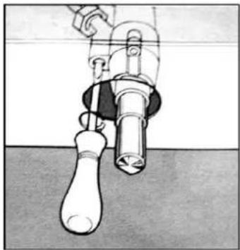
natural_image
Illustration of a mechanical device with a handle and lever, no visible text or symbolsFig.7
Checking the adjusted flame:heat the burner at full open position for 10 minutes. The turn the knob into the saving setting. The flame should not extinguish nor move to the nozzle. If it goes off or moves over to the nozzle, readjust the valves.
Note.
It is up to the used to request converting the appliance to another gas type if so required by the local conditions at a licensed gas fitter/ service.
Flame selection
At the burners adjusted correctly, the flames should be light blue, and the inner cone should be clearly visible. The size of flame depends on the position of the related burner control knob.

Fig.8
See also fig.8 for various operating options(flame size selection); the burner should be set at a large flame during the initial phase of cooking to bring the food to boiling, and then the knob should be turned to the saving flame position to maintain the cooking. It is also possible to adjust the flame size stepless.
It is prohibited to adjust the flame in the range between the Burnner OFF and Burner ON large flame positions.
Significant quantities of energy can be saved if the appliance is used correctly, parameters set correctly, and appropriate cookware is used. The savings can be as follows:
• Up to 60 per cent savings when proper pots are used,
- Up to 60 per cent savings when the unit is operated correctly and the suitable flame size is chosen..
It is a prerequisite for efficient and energy-saving iteration of the cooktop that the burners are kept clean at all times
(in particular the flame slots and nozzles).
TABLE 2: Adapting to different types of gas
| Burner | Type of Gas | Pressure | Nozzle diameter | Nominal Charge | Reduced Charge | ||||
| mbar | 1/100mm | g/h | l/h | kW | kcal/h | kW | kcal/h | ||
| Auxiliary | Natural G20 | 20 | 0.78 | — | 95.2 | 1.0 | 860 | 0.5 | 430 |
| G31 | 29 | 0.5 | 72 | — | 1.0 | 860 | 0.5 | 430 | |
| G30 | 29 | 0.5 | 72 | — | 1.0 | 860 | 0.5 | 430 | |
| G30 | 37 | 0.47 | 72 | — | 1.0 | 860 | 0.5 | 430 | |
| G30 | 50 | 0.45 | 72 | — | 1.0 | 860 | 0.5 | 430 | |
| Semi-rapid | Natural G20 | 20 | 1.03 | — | 171.4 | 1.8 | 1548 | 0.8 | 688 |
| G31 | 29 | 0.67 | 126 | — | 1.8 | 1548 | 0.8 | 688 | |
| G30 | 29 | 0.67 | 126 | — | 1.8 | 1548 | 0.8 | 688 | |
| G30 | 37 | 0.62 | 126 | — | 1.8 | 1548 | 0.8 | 688 | |
| G30 | 50 | 0.59 | 126 | — | 1.8 | 1548 | 0.8 | 688 | |
| Rapid | Natural G20 | 20 | 1.28 | — | 285.6 | 3.0 | 2580 | 1.1 | 946 |
| G31 | 29 | 0.85 | 195 | — | 3.0 | 2580 | 1.1 | 946 | |
| G30 | 29 | 0.85 | 195 | — | 3.0 | 2580 | 1.1 | 946 | |
| G30 | 37 | 0.81 | 195 | — | 3.0 | 2580 | 1.1 | 946 | |
| G30 | 50 | 0.77 | 195 | — | 3.0 | 2580 | 1.1 | 946 | |
| Triple-ring (3.6kW) | Natural G20 | 20 | 1.43 | — | 342.7 | 3.6 | 3096 | 1.8 | 1548 |
| G31 | 29 | 0.95 | 260 | — | 3.6 | 3096 | 1.8 | 1548 | |
| G30 | 29 | 0.95 | 260 | — | 3.6 | 3096 | 1.8 | 1548 | |
| G30 | 37 | 0.89 | 260 | — | 3.6 | 3096 | 1.8 | 1548 | |
| G30 | 50 | 0.84 | 260 | — | 3.6 | 3096 | 1.8 | 1548 | |
APPLIANCE MARKING
- This appliance can be used by children aged from 8 years and above and persons with reduced physical, sensory or mental capabilities or lack of experience and knowledge if they have been given supervision or instruction concerning use of the appliance in a safe way and understand the hazards involved.
- Children shall not play with the appliance. Cleaning and user maintenance shall not be made by children without supervision.
- If the supply cord is damaged, it must be replaced by the manufacturer, its service agent or similarly qualified persons in order to avoid a hazard.
- Warning: If the surface is cracked, switch off the appliance to avoid the possibility of electric shock.
- Metallic objects such as knives, forks, spoons and lids should not be placed on the surface since they can get hot
• A steam cleaner is not to be used. - Do not use a steam cleaner to clean your cooktop.
- The appliance is not intended to be operated by means of an external timer or separate remote-control system.
- WARNING: Danger of fire: do not store items on the cooking surfaces.
- The cooking process has to be supervised. A short term cooking process has to be supervised continuously.
- WARNING: Unattended cooking with fat or oil can be dangerous and may result in fire. NEVER try to extinguish a fire with water, but switch off the appliance and then cover flame e.g. with a lid or a fire blanket.
CE Certificate
It has been determined that this product complies with the LOW VOLTAGE directive (2006/95/ec), Electromagnetic Compatibility directive (2004/108/EC), and RoHS directive.
For more information related to declarations and certificates of conformity, please contact us through the mail info@infiniton.es and in the web www.infiniton.es
TECHNICAL SERVICE
If you have any questions regarding this device, please contact us: info@infiniton.es and www.infiniton.es
You can also contact our official technical service - MEGAEXIT, S.L
tel: (+34) 954 087 169
Repairs e-mail: rma@megaexit.com
www.megaexit.com
natural_image
Illustration of a hand using a tool to brush or brush over scattered black particles (no text or symbols)
natural_image
Illustration of three metallic containers crossed out by a black X (no text or symbols)Fig.1 Fig.2
natural_image
Simple line drawing of a house interior with a stove and heating elements (no text or symbols)natural_image
Simple line drawing of a house with a stove and steam rising from the chimney (no text or symbols)natural_image
Simple line drawing of a room with a door, cabinet, and steaming cup (no text or symbols)
natural_image
Technical line drawings of mechanical components, showing cross-sectional views with no visible text or symbolsN.B: Use the hook contained in the "accessoires set"
natural_image
Pure technical line drawing of a mechanical assembly without any text, numbers, or symbols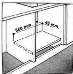
natural_image
Simple line drawing of a circular mechanical component with an arrow pointing to its center (no text or symbols)natural_image
Diagram of a mechanical assembly with a spring-loaded component inserted into a housing (no text or symbols)
natural_image
Illustration of a mechanical device with a handle and lever, no visible text or symbolsFig.7
flowchart
graph TD
    A["Circle Component"] --> B["Directional Arrow"]
    B --> C["Circular Component with Star Symbol"]
    C --> D["Arrow Down"]
    D --> E["Circular Component with Star Symbol"]
    E --> F["Arrow Up"]
natural_image
Illustration of a hand using a tool to brush or brush over scattered dark particles (no text or symbols)Fig.1

natural_image
Illustration of three metallic spray cans crossed with a diagonal line, no text or symbols presentFig.2
natural_image
Simple line drawing of a house interior with a stove, roof, and air vent (no text or symbols)exaustor é operado.
En una chimenea o chimenea ramificada (exclusivamente para aparatos de cocina)

natural_image
Simple line drawing of a house with a stove and steam rising from the chimney (no text or symbols)natural_image
Simple line drawing of a room with doors, a chimney, and a coffee cup (no text or symbols)Sala a ser ventilada
natural_image
Diagram of a door with glass doors and a vertical structure, showing a close-up of a door mechanism (no text or symbols present)natural_image
Technical line drawings of mechanical components with no visible text or symbolsnatural_image
Simple line drawing of a cabinet or enclosure with two horizontal bars and a dashed floor, no text or symbols present.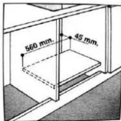
natural_image
Simple line drawing of a circular mechanical component with an arrow pointing to its center (no text or symbols)natural_image
Diagram of a mechanical assembly with a central spring and base, no text or symbols present
natural_image
Illustration of a hand holding a tool above a pipe with a bulb, against a plain background (no text or symbols)Fig.7
flowchart
graph TD
    A[" rotating object"] --> B[" rotating mirror"]
    B --> C[" rotating screen with star symbol"]
    C --> D[" rotating screen with star symbol"]


- Instruction Manual ENGLISH
- Close-up View
- NOTICE
- How To Use Your Appliance
- Gas Burners
- How to Keep Your Cooktop in Shape
- Greasing the Gas Valves
- N.B.: This procedure must be performed by a technician authorized by the manufacturer.
- Practical Advice
- Practical Advise on Using the Burners
- Practical Advice on Using the Half Fish-Kettle Burner
- Practical Advice on Using the Electric Hot Plates
- Practical Advise on Using the Broiler
- Is there a problem?
- The burner does not light or the flame is not uniform around the burner.
- The flame does not stay lighted on the model with the safety device.
- The burner does not remain on when set to "Low".
- The cookware is not stable.
- Installation Instructions for built-in
- Positioning for gas hob
- Installation of built-in stove tops
- Gas connection for gas hob
- Connection to non-flexible tube
- Connection to flexible steel tube
- Check the Seal
- Electrical Connection
- Electrical Connection for Gas Cooktop
- Adapting the Cooktop for DifferentTypes of Gas
- Adjustment of the reduced valve flow
- Valve adjustment
- Note.
- Flame selection
- It is prohibited to adjust the flame in the range between the Burnner OFF and Burner ON large flame positions.
- APPLIANCE MARKING
- CE Certificate
- TECHNICAL SERVICE
Brand : Infiniton
Model : 78MCICRG5
Category : Hot plate