
PT-D9510 - Video projector PANASONIC - Free user manual and instructions
Find the device manual for free PT-D9510 PANASONIC in PDF.


| Brand | Panasonic |
| Model | PT-D9510 |
| Product Type | Video Projector |
| Projection System | DLP™ (3-chip DMD™) |
| Resolution | 1,024 × 768 dots (XGA) |
| Aspect Ratio | 4:3 (native) |
| Brightness | 9,000 lm (Normal) / 10,000 lm (High) |
| Contrast Ratio | 1000:1 (Contrast Mode: Super) |
| Lamp | 1,600 W Xenon lamp (ET-LAD9610) |
| Lamp Life | 1,500 hours maximum (recommended replacement at 1,000 hours) |
| Projection Screen Size | 100" to 600" (2.5 m to 15 m) |
| Keystone Correction | ±10° vertical |
| Optical Lens Shift | Electric (vertical & horizontal) |
| Input Signal Compatibility | Analog RGB, Component, Video (NTSC/PAL/SECAM), Y/C, SDI, HD-SDI, TMDS |
| Network Function | LAN (RJ-45) for remote control and email alerts |
| RS-232C/RS-422 Control | Yes (D-SUB 9-pin x2) |
| Dimensions (W x H x D) | 753 mm × 428 mm × 1051 mm (29.6" × 16.9" × 41.4") |
| Weight | 100 kg (220 lb) without lens |
| Power Supply | 200-240 V AC, single-phase, 3-wire, 14 A max |
| Power Consumption | 2.2 kW (standby: ~13 W) |
| Operating Temperature | 0°C to 40°C (32°F to 104°F) |
| Remote Control | Wireless (up to 12 m) and wired (up to 15 m) |
| Air Filter Cleaning | Every 500 hours of use (approx.) |
| Safety | EMC, must be earthed; requires qualified installation |
| Manufacturer | Panasonic |
Frequently Asked Questions - PT-D9510 PANASONIC
User questions about PT-D9510 PANASONIC
0 question about this device. Answer the ones you know or ask your own.
Ask a new question about this device
Download the instructions for your Video projector in PDF format for free! Find your manual PT-D9510 - PANASONIC and take your electronic device back in hand. On this page are published all the documents necessary for the use of your device. PT-D9510 by PANASONIC.
USER MANUAL PT-D9510 PANASONIC
DLP™ based Projector Commercial Use
Operating Instructions
Models No.
PT-D9510E
PT-D9610E

natural_image
Line drawing of a Panasonic portable projector unit with control panel and remote control (no text or symbols on main body)Operating Instructions 1-94
Read these instructions completely before operating this unit.
Dear Panasonic Customer:
This instruction booklet provides all the necessary operating information that you might require. We hope it will help you to get the most performance out of your new product, and that you will be pleased with your Panasonic DLP ^™ based projector.
The serial number of your product may be found on its back. You should note it in the space provided below and retain this booklet in case service is required.
Model number: PT-D9510E / PT-D9610E
Serial number:
Contents
- Product outline 3
- Features.... 3
- IMPORTANT SAFETY NOTICE 5
- Precautions with regards to safety 6
- Precautions on handling 8
- Name and function of each part 10
- Name and function of each remote control part 11
- Before using the remote control unit.... 13 • Using the remote control unit with the cable.... 14
- Turning the power on and off 15
- On-screen menu operation guide 16
- Before using the projector .... 17 • Installing the projection lens.... 17
- Setting up the projector.... 18
- Projection distance for each projection lens (sold separately) 20
- Adjusting projector feet 24
- Setting the projection method 25
- Adjusting the lens 26
- Installing the input module 28
- Connecting the input module signal source.... 30
- Selecting the input signal / Selecting the system format 40
- Selecting the signal of ET-MD95VM2.... 41
- Registering input signal data 42
- Using the RGB REALITY mode 46
- Adjusting the picture automatically 47
- Adjusting the picture manually.... 49
- Adjusting the blanking 52
- Adjusting the clamp position / Picture mute function 53
- Adjusting the keystone(trapezoidal distortion) 54
- Adjusting the picture to the desired setting 55
- Power up function 62
- Contrast switching function 63
- When inputting BETACAM with YCbCr 480i 64
- Method of switching input impedance (signal level) for sync 64
- Displaying a test pattern 65
- Displaying the projector settings 66
- Adjusting the edge blending.... 67
- Adjusting the color matching 68
- Setting and specifying ID numbers 69
- Using the RS-232C connectors 71
- Selecting the RS-422 serial interface 75
- Using the network module 77
- Cleaning the air filter 87
- Replacing the lamp unit 88
- Before asking for service 89
- Specifications 90
- Sold separately (Optional accessories) 92
- Dimensions 93
Product Outline
This is a high-luminance DLP ^™ based projector which is powered by a single-phase, 3-wire type 200 V–240 V power supply. It utilizes three RGB DMD ^™ chips and a high-output xenon lamp. By fitting a projection lens and input module (sold separately) in accordance with the setting-up location and the type of input signal, it can project images onto screens from 2,5 m (100 inches) to 15 m (600 inches) in size.
By installing an input module (sold separately), the unit can handle various types of RGB signals, chrominance signals for high-vision TMDS (Transition Minimized Differential Signalling)-type digital interface, and also NTSC, NTSC4.43, PAL, SECAM, PAL-M, PAL60, PAL-N video signals, Y/C signals and serial digital (SDI) signals. etc.
Besides this, the projector is equipped with an RS-232C / RS-422 connector so that it can be controlled by means of a personal computer or signal selector.
Other functions available include selection of the projection method (ceiling/floor/rear), an ID number assignment function which is useful for controlling multiple projectors simultaneously, keystone(trapezoidal distortion)correction and a lens focus/position adjustment (optical axis shift) function. All settings and adjustments during the setting-up process can be carried out easily by using on-screen menus.
In addition, a self-diagnosis display function is also provided. This function generates and displays a two-digit error code to notify you if a problem occurs with operation of the projector.
DMD™ chip's aspect ratio is 4:3 on the PT-D9510E or 5:4 on the PT-D9610E.
Features
Contrast of 1000:1 realized
A contrast of 1 000 : 1 (Contrast mode; When super), which match that of e-cinema is realized using a new 1 600 W xenon lamp and luminous control technology.
Network functions are standard equipment
The unit can be controlled from a PC using a LAN interface, and also has an e-mail automatic send function, so the implementation of a remote control or central control system for handling unit problems is easy.
High-density, high-quality computer images can also be projected
The projector utilizes a DLP ^™ (Digital Light Processing) system which incorporates an 0.9-inch(for the PT-D9510E)/1.1-inch (for the PT-D9610E) DMD ^™ (Digital Micromirror Device) having a display resolution of 1 024 x 768 dots(for the PT-D9510E)/1 280 x 1 024 dots(for the PT-D9610E) that produces a three-layer image from R, G and B layers.
This system produces images with high resolution and color reproduction which is faithful to the source. Because it can handle dot clock frequencies ranging from 20 MHz to 162 MHz, computer images with signal resolutions of up to 1 600 x 1 200 dots can also be input. However, if the display resolution is greater than 1 024 x 768 dots (for the PT-D9510E)/1 280 x 1 024 dots (for the PT-D9610E), A-PIC (Advanced Panasonic Intelligent Compression) automatically converts the image to a resolution of 1 024 x 768 dots (for the PT-D9510E)/1 280 x 1 024 dots (for the PT-D9610E) without causing any lines or characters to disappear, and without causing any flickering.
A new processing circuit for moving images provides excellent moving image quality
The adoption of a new type of processing circuit exclusively for moving images converts the signals to images which are comfortable to view with no flickering or loss of quality from the image source.
Features
Projects a wide range of image sizes from 2,5 m (100 inches) to 15 m (600 inches)
By attaching different projection lenses (sold separately) that match the requirements of the setting-up location, images of any size between 2,5 m (100 inches) and 15 m(600 inches) with an aspect ratio of 4:3(PT-D9510E), 5:4(PT-D9610E) can be projected, depending on the projection distance. When using the fixed focus lens, the available picture size is from 2,5 m (100 inches) to 4.5 m (180 inches) diagonal for the PT-D9510E, and from 2,5 m (100 inches) to 5 m (200 inches) diagonal for the PT-D9610E.
The flexibility in installation format (ceiling/floor/rear), keystone compensation, and optical axis shifting capability combine to allow for installation in limited spaces.
A variety of different input sources can be used
By installing input modules (sold separately), the unit can handle various video sources, including: analog RGB signals, component signals for high-vision etc., PC digital signals (TMDS), video signals (NTSC, PAL, SECAM, NTSC4.43, PAL-M, PAL-60, PAL-N), Y/C signals, and serial digital (SDI) signals. Up to three input modules can be installed, and there are no limitations on module combinations.
Compatible with high-resolution systems used for multi-screen projection.
This projector is equipped with a system (Edge Blending adjustment and Color Matching adjustment) to blend edges of images projected from several projectors to create a large high-resolution screen. A high-resolution system structure can be created without purchasing separately sold units and is thereby cost-saving
Other useful functions also included
In addition to an on-screen setting display function, the projector is also provided with a built-in memory which can store up to 64 signal sources plus several test patterns for checking adjustment levels.
In addition, a self-diagnosis display function is also provided. This function generates and displays a two-digit error code to notify you if a problem occurs with operation of the projector.
Projection lenses which are sold separately are required for the operation of this projector. Please select the lenses which are best suited to the setting-up location for the projector.
Note:
Purchase of this equipment includes the rights to use this software (the built-in microcomputer and information recorded on ROMs) but does not grant copyrights. Do not reverse engineer, change or modify the software. The guarantee will not be valid for any malfunctions caused by such actions.
Trademark Acknowledgements
- Digital Light Processing, DLP, and Digital Micromirror Device, DMD are registered trademarks of the Texas Instruments.
• VGA and XGA are trademarks of International Business Machines Corporation. - S-VGA is a registered trademark of the Video Electronics Standards Association.
- "Microsoft Windows" is a registered trademark of the Microsoft Corporation (U.S.A.) in the U.S. and other countries.
- “Netscape” and “Netscape Navigator” are registered trademarks of the Netscape Communications Corporation in the U.S. and other countries.
All other trademarks are the property of the various trademark owners.
IMPORTANT SAFETY NOTICE
WARNING: THIS APPARATUS MUST BE EARTHED.
WARNING: To prevent damage which may result in fire or shock hazard, do not expose this appliance to rain or moisture.
WARNING: To prevent electric shock, do not remove cover. No user serviceable parts inside. Refer servicing to qualified service personnel.
Machine Noise Information Ordinance 3. GSGV, January 18, 1991: The sound pressure level at the operator position is equal or less than 70 dB (A) according to ISO 7779.
For a safe Operation, the unit must connect to a Connector which have a 16 A Installation fuse in the Line.
Precautions with regards to safety
Read these operating instructions thoroughly and check all necessary safety precautions when setting up the projector in order to avoid accidents.
WARNING
Setting-up
Installation should only be carried out by a qualified technician.
- In order to maintain full safety and precision during installation, such work should only be carried out by a qualified technician.
At least three people are needed to set up the projector.
- This projector is manufactured with high precision and is very heavy. If only one person attempts to install or move the projector by himself, the projector may be damaged or injury may result. Always make sure that at least three people are available to transport and install the projector.
Check the strength of the installation location.
- This projector weight 100 kg(220 lb). When coupled with the ceiling mount bracket (sold separately), the total weight becomes 129 kg(283.8 lb). If the installation location is not strong enough to bear the weight, carry out any reinforcement measures that may be necessary to ensure that the installation location will be free of any problems regarding strength and safety.
Avoid installing the projector in any of the following places:
- Places which are subject to vibration or shocks ... Vibration and shocks may cause malfunctions or accidents.
- Next to sprinklers or sensors ....
- Near high-voltage power lines or motors ....
- Places with adverse ambient conditions ....
Vibration and shocks may cause malfunctions or accidents. Heat produced by the projector may cause sensors to operate incorrectly or sprinkler systems to be activated, which could cause problems.
Such power sources may cause interference.
Avoid places which are extremely dusty, where oil fumes or vapor are present, and where the ambient temperature is outside the range of 0 ^ - 40 ^(32 ^ - 104 ^) or the ambient humidity is outside the range of 10 % - 80 % . If the projector is installed in such places, operating problems, fire or electric shocks may result.
Do not connect any power supply to the projector other than one with power supply voltage indicated (single-phase, 3-wire, 200 V–240 VAC)
- If the wrong power supply is connected, the projector may malfunction, and fire or electric shocks may result.
A special ceiling mount bracket (sold separately) is required for ceiling installation.
- If suspending the projector from a ceiling, you must purchase and use the special ceiling mount bracket (ET-PKD95).
Use commercially-available screens.
- Select a screen which matches the projection method to be used and the place of use.
Keep external light away from the screen.
- Do not allow light from any sources other than the projector fall on the screen. If the screen is illuminated by such external light, the projected image will lose its high contrast and will not be so easy to see.
Allow enough space around the projector for maintenance to be carried out.
- Leave at least 80 cm of free space on all sides of the projector to allow enough room for adjustments and maintenance to be carried out.
Always connect to a secure earth.
- Connect an earth wire to the earthing screw marked with = next to the MAIN POWER switch. Then connect this earth wire to a secure earthing terminal somewhere inside the room.
If the projector is used without the earth wire connected, electric shocks may result.

When using the projector
Do not look into the lens while the projector is being used.
- Strong light is emitted from the projector's lens. If you look directly into this light, it can hurt and damage your eyes.
Do not place the projector on top of surfaces which are sloped or unstable.
- The projector may fall down or tip over.
Do not place any objects on top of the projector.
- If water spills onto the projector or foreign objects get inside it, a short-circuit may occur which could result in fire or electric shocks. If any foreign objects get inside the projector, please consult an Authorized Service Centre.
Do not stick any foreign objects into the projector.
- Do not insert any metal objects or flammable objects into the ventilation holes or drop them onto the projector, as doing so can cause fire or electric shocks to occur.
Do not cover the air outlet.
- Doing so may cause the projector to overheat, which can cause fire or damage to the projector.
Do not remove the cover or modify it in any way.
- High voltages which can cause severe electric shocks are present inside the projector. For any inspection, adjustment and repair work, please contact an Authorized Service Centre.
Do not spill water on the projector.
- This can cause fire or electric shocks to occur.
Securely insert the power cord plug as far as it will go.
- If the plug is not fully inserted, heat may be generated which could cause fire. If the plug is damaged or the wall socket plate is loose, they should not be used.
Do not handle the power cord plug with wet hands.
- Doing so may cause electric shocks to occur.
Do not do anything that might damage the power cable.
- Do not damaged the cable, make any modifications to it, place heavy objects on top of it, heat it, place it near any hot objects, twist it, bend it excessively or pull it. To do so may cause fires and electric shocks to occur. If the power cable becomes damaged, have it repaired at an Authorized Service Centre.
Clean the power cable regularly to prevent it from becoming covered in dust.
- If dust builds up on the power cord plug, the resultant humidity can damage the insulation, which could result in fire. Pull the power cord out from the wall outlet and wipe it with a dry cloth.
- If not using the projector for an extended period of time, pull the power cord plug out from the wall outlet.
If a problem occurs during use
If a problem occurs (such as no picture), or if smoke or an abnormal odor starts to come out from the projector, immediately pull the power cord plug out from the wall outlet.
- If you continue to use the projector in this condition, fire or electric shocks could result. After checking that the smoke has stopped coming out, contact an Authorized Service Centre so that the necessary repairs can be mode. Repairing the projector yourself is extremely dangerous, and it should never be done.
If water or foreign objects get inside the projector, if the projector dropped, or if the cabinet becomes damaged, disconnect the power cord plug immediately.
- A short circuit may occur, which could cause fire. Contact an Authorized Service Centre for any repairs that need to be made.
Caution!
- Do not reach for the openings beside the optical lens, during horizontal or vertical movements of the lens there is a injury hazard.
Precautions on handling
CAUTION
Setting-up
The following points should always be observed when setting up this projector.
A dedicated power supply must be used.
- Ask the place of purchase to carry out any electrical work which may be required to provide a 14 A, 200 V–240 V AC (single phase) power supply for the projector alone to use.
Avoid setting up in places which are subject to vibration or shocks.
- If the projector is set up in a location with strong vibration, such as near a motor, or if it is installed inside a vehicle or on board a ship, the projector may be subjected to vibration or shocks which can damage the internal parts and cause malfunctions or accidents. Accordingly, set up the projector in a place which is free from such vibrations and shocks.
Do not place the projector near high-voltage power lines or motors.
- If the projector is set up near high-voltage power lines or motors, it may be subjected to electrical interference.
The projection distance will vary depending on the projection lens (sold separately) which is used.
- Select a projection lens which is suitable for the amount of space available at the setting-up location.
If installing the projector to the ceiling, be sure to have a qualified technician carry out the work.
- If suspending the projector from the ceiling, you will need to obtain the ceiling mount bracket which is sold separately. Also be sure to have the work performed by a qualified technician.
Do not move the projector after it has been installed and adjusted.
- After installation and adjustment of the projector have been completed, do not change the distance from the projector to the screen, and do not move the position of the projector, otherwise the colours may become unbalanced and readjustment may be necessary. Be particularly careful of this when the projector is installed using the floor method.
Allow enough space around the projector for maintenance to be carried out.
- Leave at least 80 cm(2.6 feet) of free space on all sides of the projector to allow enough room for adjustments and maintenance to be carried out.
We are in effort to hold your environmental clean.
Please bring the non repairable unit your Dealer or a Recycling Company.
Notes on use
In order to get the best picture quality
- If outside light or light from indoor lamps is shining onto the screen, the images projected will not have good contrast. Draw curtains or blinds over any windows, turn off any fluorescent lights near the screen and cover any highly-reflective floor and wall surfaces with carpet or wallpaper to prevent reflection.
Do not touch the surface of the projection lens with your bare hands.
- Do not touch your hands against the surface of the lens. If the surface of the lens becomes dirty from fingerprints or anything else, this will be magnified and projected onto the screen.
About the screen
- If the screen you are using is dirty, damaged or discoloured, attractive projections cannot be obtained. Do not apply any volatile substances to the screen, and do not let it become dirty or damaged.
Cleaning and maintenance
Always disconnect the power plug from the power source as a safety precaution before carrying out cleaning and maintenance.
Wipe the cabinet with a soft, dry cloth.
- If the cabinet is particularly dirty, soak the cloth in water with a small amount of neutral detergent in it, squeeze the cloth very well, and then wipe the cabinet. After cleaning, wipe the cabinet dry with a dry cloth. If using a chemically-treated cloth, read the instructions supplied with the cloth before use.
Do not wipe the lenses with a cloth that is dusty or which produces lint.
- If any dust or lint gets onto the lenses, such dust or lint will be magnified and projected onto the screen. Use the blower end of a vacuum cleaner to clean any dust and lint from the lens surfaces, or use a clean, soft cloth to wipe off any dust or lint. When wiping the surface of the lens, be sure to wipe in a single direction. If you move the cloth over the lens surface in different directions, it may cause any dirt to be rubbed into the surface of the lens instead of being cleaned away.
Name and function of each part
POWER button
This button is used to turn the projector power supply on and off.
- This button is enabled while the MAIN POWER switch is ON.
SYSTEM SELECTOR button
This button is used to select RGB, RGB REALITY, or YPBPR (YCbCr) signal or switch between video and digital-serial signal formats.
Arrow buttons
These buttons are used to select and adjust items in the on-screen menus.
LENS button
This button is used to select the mode for adjusting the lens.
PIC-MUTE button
This button is used to temporarily halt the projection of a picture.
Network terminals
These terminals are used to LAN interface and this equipment has a function for automatically sending e-mail when the equipment is abnormal, so a system for remote control or central control can be easily realized.
Handle
MAIN POWER switch
This switch turns the main power supply to the projector on and off.
REMOTE IN 2 input/output connector
This connector is used to connect a wired remote control unit to control the projector when using it in a multi-screen projection system.
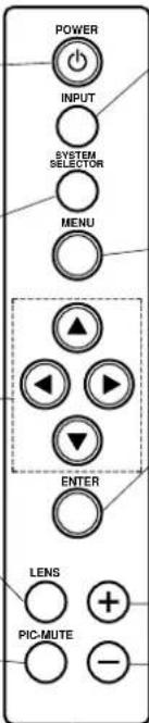
INPUT button
This button is used to change the input between INPUT 1 / INPUT 2 / INPUT 3.
If there are several input terminals in a single input slot, the selection will change in order between all input terminals available for that slot.
MENU button
This button is used to make the MENU screen and the respective adjustment screens appear on the projection screen, and to return to a previously-displayed screen.
ENTER button
This button is used to accept and activate items selected in the on-screen menus.
Control level buttons
These buttons are used to adjust the BRIGHT, CONTRAST, COLOUR and TINT and to adjust the lens.
Power indicator
When the MAIN POWER switch is pressed, this indicator becomes red and the projector switches to standby mode. When the POWER button on the remote control unit or the projector operating panel is pressed, the indicator changes to green, and after a brief period, a picture is then projected.
Installation bays for input modules (sold separately)
(These are designated as slot 1, slot 2 and slot 3 in order from the top.)
RS-232C/RS-422 OUT connector
When using a personal computer to control a multi-screen projection system, this connector is used to connect this projector to the RS-232C/RS-422 IN connector of the next projector.
RS-232C/RS-422 IN connector
If you would like to use a personal computer to control the projector operation, connect the RS-232C/RS-422 output connector of the computer to this terminal.
REMOTE IN 1 connector
This connector is used to connect an external control circuit in order to turn the projector power on and off and to change the input source externally.
NOTE
- The handle of the product may be not be depicted in the illustration on some pages.
Name and function of each remote control part
STD (standard) button
This button is used to reset all of the projector adjustment values (BRIGHT, CONTRAST, COLOUR, TINT and SHARPNESS) to the default levels which were set at the time of shipment from the factory. It is pressed after the respective adjustment mode screen has been displayed.
SYSTEM SELECTOR button
This button is used to select RGB, RGB REALITY, or YP_BP_R (YCbCr) signal or switch between video and digital-serial signal formats.
POWER button
This button is used to turn the projector power supply on and off. - This button is enabled while the MAIN POWER switch is ON.
Input select buttons
These buttons are used to change the input between INPUT 1 (slot 1)/INPUT 2 (slot 2)/INPUT 3 (slot 3). If there are several input terminals in a single input slot, the selection will change in order between all input terminals available for that slot. (RGB button is invalid)
CONTRAST button
This button is used to select the mode for adjusting the picture contrast.
BRIGHT buttons
This button is used to select the mode for adjusting the picture brightness.
Numeric buttons
These buttons are used to specify this projector when it is being used in a multi-screen projection system. In addition, they are used to enter ID numbers when selecting IDs, and to enter passwords.
PIC-MUTE button
This button is used to temporarily halt the projection of a picture.
ON SCREEN button
This button is used to turn the on-screen display function on and off.
NEXT button
If the ID SELECT button is being pressed and held, the tens digit of the ID number then changes each time the NEXT button is pressed.
ID SELECT button
When the projector is being used in a multi-screen projection system, this button is used to select the mode for specifying which projector is to be operated.

LENS button
This button is used to select the mode for adjusting the lens.
ID ALL button
When the projector is being used in a multi-screen projection system, this button is used to select the mode for controlling all projectors using a single remote control unit.
NOTE
When the projector is being used in a multi-screen projection system, to use the remote control unit, set the ID number of the projector. Refer to page 69 for details.
Name and function of each remote control part (continued)

Rear of remote control unit

If the button illumination is flashing
This indicates that the remote control unit batteries are nearly flat. Replace them with new batteries.
LIGHT button
The buttons on the front of the remote control unit will be illuminated while this button is pressed.
The button illumination will switch off approximately 10 seconds after this button is released.
Battery compartment cover
Remove this cover and insert four AA-size batteries in order to use the remote control unit.
Before using the remote control unit
Inserting the batteries
- Insert the AA batteries supplied with the remote control unit, making sure that the polarities are correct.
- The batteries also need to be inserted when the remote control unit is connected to the projector using the remote control cable.
1 Open the battery compartment cover.

Push the mark firmly in the direction of the arrow to slide the cover, and then pull it toward you to remove it.
2 Insert the batteries.

Insert the batteries so that their direction matches the polarity markings inside the compartment.
3 Close the battery compartment cover.
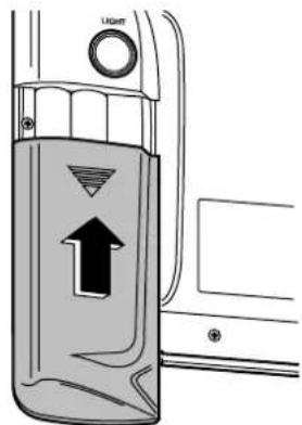
Return the battery compartment cover to its original position.
Note on using the batteries
The following should be observed in order to prevent damage to or leaking of the batteries.
- Do not mix old and new batteries of batteries of different types.
-
Do not burn spent batteries or put them in with combustible garbage.
-
Do not use rechargeable (Ni-Cd) batteries.
- Do not recharge the batteries.
- Do not short the (+) and (-) terminals.
- Do not disassemble the batteries.
Notes when using the remote control unit
- Do not spill any liquids onto the remote control unit.
- Do not drop the remote control unit.
Because the memory in the remote control unit is reset when the batteries are replaced after the projector has been set up, you will need to reset the ID numbers.
Attaching the strap
A strap is provided with the remote control unit. You can use this strap to hang the remote control unit around your neck for easy carrying. Attach the strap as shown in the illustrations below.
- Open the battery compartment cover Attach the supplied strap as shown in this illustration and close battery compartment cover.

Operating range of remote control unit
- When using remote control unit without the cable, refer to the illustration below for operating range.

NOTE
If facing the remote control unit towards the screen to operate the projector, the operating range of remote control unit will be limited by the amount of light reflection loss caused by the characteristics of the screen used.
Using the remote control unit with the cable
The remote control unit can be connected to the projector using the accessory remote control cable.
This cable should be connected to the REMOTE IN2 IN terminal at the front of the projector and to the remote control cable terminal.
Note:
- The maximum length for the cable used to connected the remote control unit is 15 m (49 feet).
[Remote control unit]

To REMOTE IN2 IN terminal
[Projector]

Accessory remote control cable
- Using REMOTE IN 1 Terminal
[Projector]

Because each pin of the REMOTE IN 1 terminal is controlled by its open (H) or short (L) as shown in the table below, the addition of an external control circuit allows the external control for the projector power supply on and off, the change of the input terminal, and the switching of the input signal system.
- To perform external contact control of the projector, turn off the MAIN POWER switch of the projector, then set pin 9 of the REMOTE IN 1 terminal to the external contact control mode (short) using the external control circuit, and then turn on the MAIN POWER switch of the projector.
- When controlling the projector using the external control circuit, the external contact control mode (short) at pin 9 disables the buttons on the projector operating panel and the remote control unit for the projector power supply on and off and the change of the input terminal functions.
D-SUB9P
REMOTE IN1 Terminal
| 1 | 6 |
| 2 | 7 |
| 3 | 8 |
| 4 | 9 |
| 5 |
| Terminals | Open(H) | Short(L) | |
| 1 | GND | —— | GND |
| 2 | POWER | OFF | ON |
| 3 | RGB | Other | RGB |
| 4 | INPUT 1 | Other | INPUT 1 |
| 5 | INPUT 2 | Other | INPUT 2 |
| 6 | INPUT 3 | Other | INPUT 3 |
| 7 | LINE / Y / C | LINE | Y / C |
| 8 | PIC-MUTE | OFF | ON |
| 9 | RST / SET | Remote control | External contact control |
Turning the power ON and OFF
Always be sure to follow the procedure given below to turn the projector power on and off.
flowchart
graph TD
    A["1"] --> B["Main power ON<br>(The power indicator will become red)"]
    B --> C["Press the [1"] side of the MAIN POWER switch at the front of the projector.
(The projector will change to standby mode.)]
    C --> D["Wait about 3 seconds"]
    E["While projecting a picture<br>(The power indicator is green)"] --> F["2"]
    F --> G["Standby ON<br>(The power indicator will become green)"]
    G --> H["Press the POWER button on the remote control unit or on the projector operating panel."]
    H --> I["After about 20 seconds"]
    I --> J["Picture projected3"]
    K["1"] --> L["Standby OFF<br>(The power indicator will become red from green after the cooling fan has stopped)"]
    L --> M["Press the POWER button on the remote control unit or on the projector operating panel."]
    M --> N["Wait about 5 minutes"]
    O["Main power OFF2"] --> P["A picture will then be projected."]
    P --> Q["Press the [O"] side of the MAIN POWER switch at the front of the projector.
(The power will then turn off.)]
NOTE
- The projector will continue to draw approximately 13 W of power when it is in standby mode, even after the cooling fan has stopped.
- The lamp cooling fan will continue to operate for approximately five minutes after the power is turned off. At the same time, the self-diagnosis display “FC” will blink.
Do not disconnect the power cord from the power outlet or do not open any circuit breakers while the cooling fan is still operating.
- When projecting a picture for the first time after setting up the projector, first press the LENS button on the remote control unit or the projector operating panel, and then use the control level buttons (+ and -) to adjust the basic focus.
- Turning on the power at an ambient temperature of about 0^ may require a warm-up time of approximately five minutes to start projecting a picture.
Codes such as "C1, C2, or C3" will appear in the self-diagnosis display during the warm-up.
After the warm-up, the self-diagnosis display will turn off and the projector will project a picture.
- If the ambient temperature is too low and the warm-up time exceeds five minutes, the power will automatically be turned off as an abnormal condition. In this case, increase the ambient temperature to 0^ or higher and then perform the operations "Main power ON Standby ON" again.
On-screen menu operation guide
The figure below shows on-screen displays for any desired setting, starting with the MAIN MENU, and ending with its sub-menu.
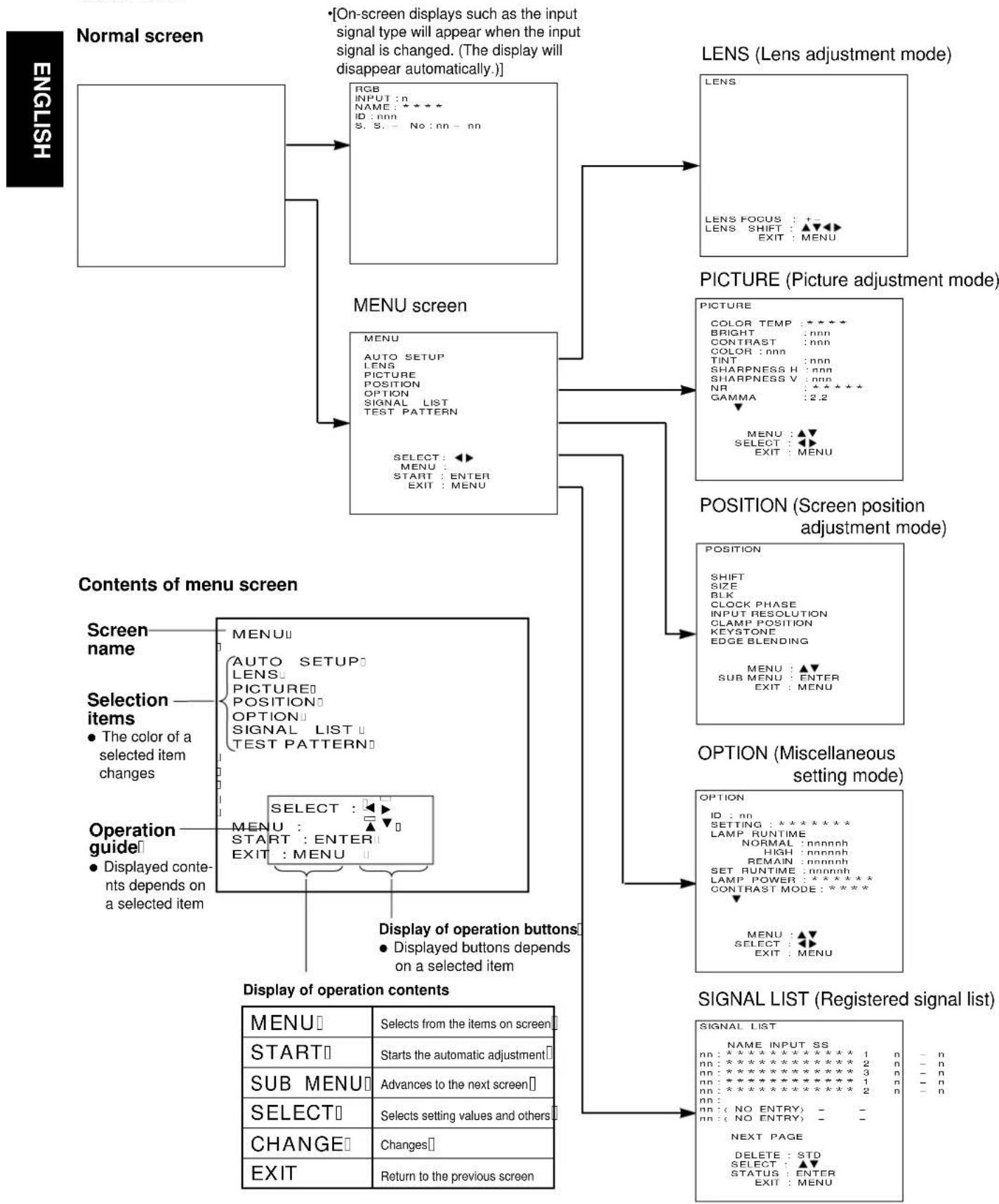
flowchart
graph TD
    A["Normal screen"] --> B["RGB INPUT: n<br>NAME: *****<br>ID: nnn<br>S. S. - No: nn - nn"]
    B --> C["ON-screen displays such as the input signal type will appear when the input signal is changed. (The display will disappear automatically)."]
    C --> D["LENS (Lens adjustment mode)"]
    D --> E["LENS FOCUS: +-<br>LENS SHIFT: ▲▼▶<br>EXIT: MENU"]
    C --> F["MENU screen"]
    F --> G["AUTO SETUP<br>LENS<br>PICTURE<br>POSITION<br>OPTION<br>SIGNAL LIST<br>TEST PATTERN<br>SELECT: ◀▶<br>MENU: START: ENTER<br>EXIT: MENU"]
    G --> H["PICTURE (Picture adjustment mode)"]
    H --> I["PILOTURE<br>COLOR TEMP: *****<br>BRIGHT: nnn<br>CONTRAST: nnn<br>COLOR: nnn TINT SHARPNESS H: nnn SHARPNESS V: nnn NR: *****<br>GAMMA: 2.2<br>MENU: ▲▼<br>SELECT: ◀▶ EXIT: MENU"]
    F --> J["POSITION (Screen position adjustment mode)"]
    J --> K["POSITION<br>SHIFT SIZE BLK CLOCK PHASE INPUT RESOLUTION CLAMP POSITION KEYSTONE EDGE BLENDING<br>MENU: ▲▼ SUB MENU: ENTER EXIT: MENU"]
    K --> L["OPTION (Miscellaneous setting mode)"]
    L --> M["OPTION ID: nn<br>SETTING: *****<br>LAMP RUNTIME NORMAL: nnnnhh HIGH: nnnnhh REMAIN: nnnnhh SET RUNTIME: nnnnhh LAMP POWER: *****<br>CONTRAST MODE: *****<br>MENU: ▲▼<br>SELECT: ◀▶ EXIT: MENU"]
    M --> N["SIGNAL LIST (Registered signal list)"]
    N --> O["SIGNAL LIST<br>NAME INPUT SS<br>nn: ***** * * * * * * * * * * * * * * * * * * * * * * * * * * * * * * * * * * * * * * * * * * * * * * * * * * * * * * * * * * * * * * * * * * * * * * * * * * * * * * * * * * * * * * * * * * * * * * * * * * * * *<br>    O --> P[CONTENTS OF MENU SCREEN"]
    P --> Q["Screen name<br>MENU"]
    Q --> R["AUTO SETUP<br>LENS"]
    R --> S["PICTURE"]
    S --> T["POSITION"]
    T --> U["SIGNAL LIST"]
    U --> V["OUTPUT GUIDE"]
    V --> W["SELECT: ◀▶ MENU : START : ENTER EXIT : MENU"]
    W --> X["Display of operation buttons"]
    X --> Y["Display of operation contents"]
    Y --> Z["MENU"]
    Z --> AA["START"]
    AA --> AB["SUB MENU"]
    AB --> AC["SELECT"]
    AC --> AD["CHANGE"]
    AD --> AE["EXIT"]
    AE --> AF["Return to the previous screen"]
Before using the projector
The projection lenses and input modules which are available for use with this projector need to be purchased separately, and must be installed to the projector before the projector can be used.
NOTE
- Obtain the required projection lenses and input modules beforehand in accordance with the projection distance and the system used.
- When installing an optional input module, refer to page 28 for details.
Installing the projection lens
Install a projection lens (sold separately) which is appropriate for the projector setting-up conditions.
Setting procedure
①Remove the lens caps (one each at front and back) from the projection lens.
②Insert the projection lens into the lens holder and turn it clockwise until it is securely in place.

NOTE
- Because a projection lens is considerably heavy, be careful not to drop it during installation.
- If inserting the projection lens into the lens holder too strongly, the lens may jam into the holder. To prevent this problem, do this work carefully.
Setting up the projector
- After determining the installation position of the projector and screen in consideration of the audience positions, install them according to the chapter "Projection distance for each projection lens (sold separately)" on pages 20 - 23.
Installing to the floor (Including the direct rear-mounting)
- Installing drawing of the screen and the projector (unit : mm / (inches))
![[Side view] Screen SH A C L](/content/2026/06/1191165/images/f2b11ef27708f33294f645d6f0f2ab053b672266948a97b283eedf32bdca5c9e.jpg)
[Top view]

- Installing the screen and the projector

![[Rear view] 188(7.4") Centre-line of screen Centre-line of projector Screen](/content/2026/06/1191165/images/37bd86c6b48c8570a57eedc66a1ea5bc03d2e88cc57374d6adadd9a7c5caefae.jpg)
L : Projection distance between the screen and the centre of the front foot of the projector.
A: Distance between the centre of the lens and the top of the setting table (including the height of a foot of the projector), 288 mm – 313 mm (11.5" – 12.5") (The height of each foot is adjustable.)
C: Distance between the bottom of the foot and the floor (height of the setting table) Set this distance so that the distance between the centre of the lens and the floor can become equal to that between the lowest edge of the screen and the floor.
• Installing the screen
After determining the installation position of the screen in consideration of the screen characteristics and the audience positions, install it using the procedure specified by screen manufacture.
• Installing the projector
Install the projector by observing the items below and referring to the above "Installation drawing of the projector and screen" and the drawing at left.
- Set the lens centre position of the projector to the same height as the lower edge of the effective height of the screen. (If the projector position is lower than the reference position, prepare a setting table that has a height of the above "C".)
- Set the centre line of the projector to the position facing the vertical line 188 mm(7.4") away from the centre line of the screen to the right.
- Set the centre position of the front foot of the projector to the position of the projection distance (L) specified according to the projection lens and the target picture size.
Installing to the ceiling (Including direct rear-projection)
- Using the projector by installing to the ceiling requires an optional ceiling mount bracket (ET-PKD95).
For the projection distance (L), refer to the chapter "Projection distance for each projection lens (sold separately)" on pages 20 - 23.
For the procedures to install the ceiling mount bracket on the projector and mount the suspension bolts on the ceiling surface, refer to the installation instructions supplied with ET-PKD95.
1. Installing drawing of the screen and the projector (unit : mm (inches))
[Side view]

[Rear view]

[Bottom view]

2. Position of the ceiling mount bracket on the ceiling

L: Projection distance between the screen and the centre of the front foot of the projector
B: Distance between the centre of the lens and the top end of the ceiling mount bracket. (281 mm (11.24"))
D: Distance between the centre of the front foot of the projector and the centre of the ceiling mount bracket. (335 mm (13.2"))
- Locating the positions to mount the suspension bolts on the ceiling surface
Locate the centre-hole position of the ceiling side of the optional ceiling mount bracket (ET-PKD95) by the procedure below. For the procedure to install to the ceiling, refer to the installation instructions of the optional ceiling mount bracket (ET-PKD95).
- Put a mark on the ceiling surface at the upwardly straight point of a distance of 188 mm(7.4") from the screen centre to the left.
- Draw a line in a direction at right angles to the screen from marked point.
- Put another mark on the ceiling surface at the point where the centre position of the ceiling side of the ceiling mount bracket will be set. The point is at a distance of D + L from the screen.
Projection distance for each projection lens
(sold separately)
The required projection distance depends on not only the target picture size but also the type of an optional projection lens. Obtain the appropriate projection lens for the installation space by referring to the projection distance for each projection lens shown in the table below and on the next page.
L : Projection distance
SH : Effective height of screen

Projection distance measurements for PT-D9510E (screen aspect ratio: 4:3)
unit: mm (feet/inches)
| Picture size | Screen size | Projection distance | |||||||
| Zoom lens | Fixed focal lens | ||||||||
| Effective height(SH) | Effective width(SW) | ET-D95LE1 (1.5-2.5:1) | ET-D95LE2 (2.5-4.0:1) | ET-D95LE3 (4.0-7.0:ET-D95LE9(0.8:1) | |||||
| Min. | Max. | Min. | Max. | Min. | Max. | ||||
| 2 540(100") | 1 524(5'0")(6'8") | 2 032(6'8") | 3 261(10'9")(17'1") | 5 197(17'3")(27'0") | 5 270(17'3") | 8 221(27'0") | 8 196(26'11")(26'11") | 14 142(46'5") | 2 398(7'11")(7'11") |
| 3 048(120") | 1 829(6'0")(8'0") | 2 438(8'0") | 3 870(12'9")(20'4") | 6 203(20'7")(32'3") | 6 279(20'7") | 9 833(32'3") | 9 820(32'3")(55'8") | 16 976(55'8") | 2 827(9'4") |
| 3 810(150") | 2 286(7'6")(10'0") | 3 048(10'0") | 4 784(15'9")(25'4") | 7 713(25'7")(40'2") | 7 792(25'7") | 12 251(40'2") | 12 257(40'2")(69'7") | 21 227(69'7") | 3 471(11'5") |
| 4 572(180") | 2 743(9'0")(12'0") | 3 658(12'0") | 5 698(18'9")(30'3") | 9 223(30'6")(48'1") | 9 305(30'6") | 14 669(48'1") | 14 693(48'2")(83'7") | 25 478(83'7") | 4 114(13'16") |
| 5 080(200") | 3 048(10'0")(13'4") | 4 064(13'4") | 6 307(20'8")(33'7") | 10 229(33'10")(53'5") | 10 314(33'10") | 16 281(53'5") | 16 318(53'6")(92'10") | 28 312(92'10") | —— |
| 6 350(250") | 3 810(12'6")(16'8") | 5 080(16'8") | 7 830(25'8")(41'9") | 12 745(42'1")(66'7") | 12 835(42'1") | 20 310(66'7") | 20 379(66'10")(116'1") | 35 397(116'1") | —— |
| 7 620(300") | 4 572(15'0")(20'0") | 6 096(20'0") | 9 353(30'8")(50'0") | 15 261(50'4")(79'10") | 15 357(50'4")(79'10") | 24 340(79'10") | 24 440(80'2")(139'4") | 42 482(139'4") | —— |
| 8 890(350") | 5 334(17'6")(23'4") | 7 112(23'4") | 10 876(35'8")(58'8") | 17 777(58'8")(93'6") | 17 879(58'8")(93'6") | 28 369(93'6") | 28 501(93'5") | 49 567(162'6") | —— |
| 10 160(400") | 6 096(20'0")(26'8") | 8 128(26'8") | 12 399(40'8")(66'7") | 20 293(66'11")(106'3") | 20 401(66'11") | 32 399(106'3") | 32 562(106'9") | 56 651(185'9") | —— |
| 11 430(450") | 6 858(22'6")(30'0") | 9 144(30'0") | 13 922(45'8")(77'10") | 22 809(75'2")(119'5") | 22 923(75'2")(119'5") | 36 429(119'5") | 36 623(120'1") | 63 736(209'0") | —— |
| 12 700(500") | 7 620(25'0")(33'4") | 10 160(33'4") | 15 445(50'8")(83'0") | 25 325(83'5")(132'8") | 25 445(83'5")(132'8") | 40 458(132'8") | 40 684(133'5") | 70 821(232'3") | —— |
| 13 970(550") | 8 382(27'6")(36'8") | 11 176(36'8") | 16 968(55'8")(91'4") | 27 841(91'9")(145'11") | 27 966(91'9")(145'11") | 44 488(145'11") | 44 745(146'9")(255'5") | 77 906(255'5") | —— |
| 15 240(600") | 9 144(30'0")(40'0") | 12 192(40'0") | 18 491(60'8")(99'7") | 30 357(100'0")(159'11") | 30 488(100'0")(159'11") | 48 517(159'11") | 48 806(160'0")(278'8") | 84 991(278'8") | —— |
Projection distance measurements for PT-D9510E (screen aspect ratio: 16:9)
unit: mm (feet/inches)
| Picture size | Screen size | Projection distance | |||||||
| Zoom lens | Fixed focal lens | ||||||||
| Effective height(SH) | Effective width(SW) | ET-D95LE1 (1.5-2.5:1) | ET-D95LE2 (2.5-4.0:1) | ET-D95LE3 (4.0-7.0:1) | BT-D95LE9 (0.8:1) | ||||
| Min. | Max. | Min. | Max. | Min. | Max. | ||||
| 2 540(100") | 1 245(4'1") | 2 214(7'3") | 3 534(11'7") | 5 647(18'6") | 5 721(18'9") | 8 942(29'4") | 8 922(29'3") | 15 409(50'6") | 2 589(8'6") |
| 3 048(120") | 1 494(4'11") | 2 657(8'9") | 4 197(13'9") | 6 743(22'1") | 6 820(22'5") | 10 698(35'1") | 10 692(35'1") | 18 497(60'8") | 3 057(10'1") |
| 3 810(150") | 1 868(6'2") | 3 321(10'11") | 5 193(17'3") | 8 388(27'6") | 8 468(27'10") | 13 332(43'9") | 13 346(43'9") | 23 128(75'10") | 3 758(12'4") |
| 4 572(180") | 2 241(7'4") | 3 985(13'1") | 6 188(20'4") | 10 033(32'11") | 10 117(33'2") | 15 966(52'4") | 16 001(52'6") | 27 759(91'0") | 4 459(14'8") |
| 5 080(200") | 2 491(8'2") | 4 428(14'6") | 6 852(22'6") | 11 129(36'6") | 11 216(36'10") | 17 722(58'1") | 17 771(58'3") | 30 847(101'2") | —— |
| 6 350(250") | 3 113(10'3") | 5 535(18'2") | 8 511(27'11") | 13 870(45'6") | 13 963(45'10") | 22 112(72'7") | 22 195(72'10") | 38 565(126'6") | —— |
| 7 620(300") | 3 736(12'3") | 6 641(21'10") | 10 171(33'4") | 16 611(54'6") | 16 711(54'10") | 26 502(86'11") | 26 619(87'3") | 46 284(151'9") | —— |
| 8 890(350") | 4 358(14'4") | 7 748(25'5") | 11 830(38'10") | 19 352(63'6") | 19 458(63'10") | 30 892(101'4") | 31 043(101'10") | 54 002(177'1") | —— |
| 10 160(400") | 4 981(16'4") | 8 855(29'0") | 13 489(44'3") | 22 094(72'5") | 22 205(72'10") | 35 282(115'8") | 35 467(116'4") | 61 721(202'5") | —— |
| 11 430(450") | 5 604(18'5") | 9 962(32'8") | 15 148(49'8") | 24 835(81'5") | 24 953(81'10") | 39 672(130'1") | 39 892(130'10") | 69 440(227'8") | —— |
| 12 700(500") | 6 226(20'5") | 11 069(36'4") | 16 808(55'11") | 27 576(90'5") | 27 700(90'10") | 44 062(144'6") | 44 316(145'4") | 77 158(253'7") | —— |
| 13 970(550") | 6 849(22'6") | 12 176(40'0") | 18 467(60'7") | 30 317(99'5") | 30 448(99'10") | 48 452(158'11") | 48 740(159'10") | 84 877(278'4") | —— |
NOTE:
- The projection distance listed in the table may have a variation within ± 5% .
- Keystone (trapezoidal distortion) is compensated to be smaller than the screen size.
Projection distance measurements for PT-D9610E (screen aspect ratio: 5:4)
unit: mm (feet/inches)
| Picture size | Screen size | Projection distance | Fixed focal lens | ||||||||
| Zoom lens | |||||||||||
| Effective height(SH) | Effective width(SW) | ET-D95LE5 (1.5-2.0:1) | ET-D95LE6 (2.0-2.5:1) | ET-D95LE7 (2.5-4.0:1) | ET-D95LE8 (4.0-7.0:1) | ET-D95LE9 (0.8:1) | |||||
| Min. | Max. | Min. | Max. | Min. | Max. | Min. | Max. | ||||
| 2 540(100") | 1 586(5'3") | 1 983(6'7") | 3 203(10'7") | 4 194(13'10") | 4 266(14'0") | 5 172(17'0") | 5 033(16'7") | 7 927(26'1") | 8 066(26'7") | 13 905(45'9") | 1 926(6'4") |
| 3 048(120") | 1 904(6'3") | 2 380(7'10") | 3 814(12'7") | 5 007(16'6") | 5 079(16'9") | 6 165(20'3") | 6 025(19'10") | 9 315(31'4") | 9 654(31'9") | 16 686(54'11") | 2 261(7'5") |
| 3 810(150") | 2 380(7'10") | 2 975(9'10") | 4 732(15'7") | 6 226(20'6") | 6 299(20'9") | 7 655(25'2") | 7 512(24'9") | 11 891(39'1") | 12 035(39'7") | 20 858(68'7") | 2 763(9'1") |
| 4 572(180") | 2 856(9'5") | 3 570(11'9") | 5 650(18'7") | 7 444(24'6") | 7 519(24'9") | 9 146(30'1") | 8 999(29'8") | 14 270(47'0") | 14 416(47'5") | 25 029(82'4") | 3 265(10'9") |
| 5 080(200") | 3 174(10'6") | 3 967(13'1") | 6 261(20'7") | 8 257(27'2") | 8 332(27'5") | 10 139(33'4") | 9 991(32'11") | 15 855(52'2") | 16 004(52'8") | 27 810(91'6") | 3 600(11'11") |
| 6 350(250") | 3 967(13'1") | 4 959(16'4") | 7 791(25'8") | 10 289(33'11") | 10 365(34'1") | 12 623(41'7") | 12 470(41'0") | 19 820(65'2") | 19 973(65'9") | 34 763(114'4") | —— |
| 7 620(300") | 4 760(15'8") | 5 950(19'7") | 9 320(30'8") | 12 320(40'7") | 12 398(40'10") | 15 107(49'9") | 14 948(49'2") | 23 784(78'3") | 23 941(78'9") | 41 715(137'3") | —— |
| 8 890(350") | 5 554(18'3") | 6 942(32'10") | 10 849(35'9") | 14 352(47'3") | 14 431(47'6") | 17 591(57'11") | 17 427(57'4") | 27 748(78'3") | 27 910(91'10") | 48 668(160'2") | —— |
| 10 160(400") | 6 347(20'11") | 7 934(26'1") | 12 379(40'9") | 16 383(53'11") | 16 464(54'2") | 20 074(66'0") | 19 906(65'6") | 31 712(104'4") | 31 879(104'11") | 55 620(183'0") | —— |
| 11 430(450") | 7 140(23'6") | 8 925(29'4") | 13 908(45'9") | 18 415(60'7") | 18 497(60'11") | 22 558(74'2") | 22 384(73'8") | 35 676(117'4") | 35 847(117'11") | 62 573(205'10") | —— |
| 12 700(500") | 7 934(24'6") | 9 917(32'8") | 15 438(50'10") | 20 446(67'3") | 20 530(67'7") | 25 042(82'5") | 24 863(81'10") | 39 640(130'5") | 39 816(131'0") | 69 525(228'9") | —— |
| 13 970(550") | 8 727(26'1") | 10 909(35'11") | 16 967(55'10") | 22 478(74'0") | 22 562(74'3") | 27 526(90'7") | 27 342(90'0") | 43 604(143'5") | 43 785(144'0") | 76 478(251'7") | —— |
| 15 240(600") | 9 520(31'4") | 11 900(39'2") | 18 496(60'11") | 24 509(80'8") | 24 595(80'11") | 30 010(98'9") | 29 820(98'1") | 47 568(156'6") | 47 753(157'1") | 83 430(274'6") | —— |
Projection distance measurements for PT-D9610E(screen aspect ratio: 16:9)
unit: mm (feet/inches)
| Picture size | Screen size | Projection distance | Fixed focal lens | ||||||||
| Zoom lens | |||||||||||
| Effective height(SH) | Effective width(SW) | ET-D95LE5 (1.5-2.0:1) | ET-D95LE6 (2.0-2.5:1) | ET-D95LE7 (2.5-4.0:1) | ET-D95LE8 (4.0-7.0:1) | ET-D95LE9 (0.8:1) | |||||
| Min. | Max. | Min. | Max. | Min. | Max. | Min. | Max. | ||||
| 2 540(100") | 1 245(4'1") | 2 214(7'3") | 3 558(11'8") | 4 666(15'4") | 4 738(15'7") | 5 748(18'11") | 5 609(18'6") | 8 848(29'1") | 8 987(29'7") | 15 519(51'1") | 2 120(7'0") |
| 3 048(120") | 1 494(4'11") | 2 657(8'9") | 4 241(14'0") | 5 572(18'4") | 5 645(18'7") | 6 857(22'7") | 6 715(22'1") | 10 617(34'11") | 10 759(35'5") | 18 623(61'3") | 2 494(8'3") |
| 3 810(150") | 1 868(6'2") | 3 321(10'11") | 5 265(17'4") | 6 933(22'10") | 7 007(23'1") | 8 520(28'0") | 8 375(27'7") | 13 272(43'8") | 13 417(44'2") | 23 279(76'7") | 3 055(10'1") |
| 4 572(180") | 2 241(7'4") | 3 985(13'11") | 6 289(20'9") | 8 293(27'3") | 8 368(27'7") | 10 184(33'6") | 10 035(33'0") | 15 926(52'5") | 16 074(52'11") | 27 935(91'11") | 3 615(11'11") |
| 5 080(200") | 2 491(8'2") | 4 428(14'6") | 6 971(20'9") | 9 200(30'3") | 9 276(30'6") | 11 292(37'2") | 11 142(36'8") | 17 696(58'3") | 17 846(58'9") | 31 038(102'1") | —— |
| 6 350(250") | 3 113(10'3") | 5 535(18'2") | 8 678(28'7") | 11 468(37'9") | 11 545(38'0") | 14 065(46'3") | 13 908(45'9") | 22 120(72'10") | 22 276(73'3") | 38 798(127'8") | —— |
| 7 620(300") | 3 736(12'3") | 6 641(21'10") | 10 385(34'2") | 13 735(45'2") | 13 814(45'6") | 16 837(55'5") | 16 674(54'11") | 26 554(87'4") | 26 705(87'11") | 46 557(153'2") | —— |
| 8 890(350") | 4 358(14'4") | 7 748(25'5") | 12 092(39'10") | 16 002(52'8") | 16 082(52'11") | 19 609(64'6") | 19 441(64'0") | 30968(101'11") | 31 134(102'5") | 54 317(178'8") | —— |
| 10 160(400") | 4 981(16'4") | 8 855(29'0") | 13 799(45'5") | 18 351(60'5") | 18 351(60'5") | 22 381(73'8") | 22 207(73'1") | 35 393(116'5") | 35 564(117'0") | 62 076(204'2") | —— |
| 11 430(450") | 5 604(18'5") | 9 962(32'8") | 15 506(51'0") | 20 537(67'10") | 20 620(67'10") | 25 153(82'9") | 24 974(82'2") | 39 817(131'0") | 39 993(131'7") | 69 836(229'9") | —— |
| 12 700(500") | 6 226(20'5") | 11 069(36'4") | 17 213(56'8") | 22 804(75'0") | 22 889(75'4") | 27 925(91'11") | 27 740(91'3") | 44 241(145'7") | 44 422(146'2") | 77 595(255'3") | —— |
| 13 970(550") | 6 849(22'6") | 12 176(40'0") | 18 919(62'3") | 25 071(82'6") | 25 158(82'9") | 30 697(101'0") | 30 506(100'4") | 48 665(160'1") | 48 852(160'9") | 85 355(280'10") | —— |
NOTE:
- The projection distance listed in the table may have a variation within ± 5% .
- Keystone (trapezoidal distortion) is compensated to be smaller than the screen size.
Calculation of the projection distance for each projection lens (for PT-D9510E)
If there is no reference made to the require picture size, calculate the projection distance using an expression below after obtaining the diagonal measurement (inch) of the screen you will use.
| Model No. of projection lens | Aspect ratio | Methods of calculation of Projection distance (L) Unit : mm | |
| Zoom lens | ET-D95LE1(1.5 — 2.5 : 1) | 4:3 | Min. : L = [(diagonal of screen(inches) + 12.87377) x 1000/32.82965]-177Max. : L = [(diagonal of screen(inches) + 6.79329) x 1000/19.87243]-177 |
| 16:9 | Min. : L = [(diagonal of screen(inches)/0.9179 + 12.87377)x1000/32.82965-177Max. : L = [(diagonal of screen(inches)/0.9179 + 6.79329)x1000/19.87243]-177 | ||
| ET-D95LE2(2.5 — 4.0 : 1) | 4:3 | Min. : L = [(diagonal of screen(inches) + 7.995693) x 1000/19.87243]-177Max. : L = [(diagonal of screen(inches) + 4.208911) x 1000/12.40818]-177 | |
| 16:9 | Min. : L = [(diagonal of screen(inches)/0.9179 + 7.995693)x1000/19.82683]-177Max. : L = [(diagonal of screen(inches)/0.9179 + 4.208911)x1000/12.40818]-177 | ||
| ET-D95LE3(4.0 — 7.0 : 1) | 4:3 | Min. : L = [(diagonal of screen(inches) + 3.08921) x 1000/12.31233]-177Max. : L = [(diagonal of screen(inches) + 1.052912) x 1000/7.057261]-177 | |
| 16:9 | Min. : L = [(diagonal of screen(inches)/0.9179 + 3.08921)x1000/12.31233]-177Max. : L = [(diagonal of screen(inches)/0.9179 + 1.052912)x1000/7.057261]-177 | ||
| Fixed focal lens | ET-D95LE9(0.8: 1) | 4:3 | L = 21.457 x diagonal of screen(inches) + 252 |
| 16:9 | L = 23.371 x diagonal of screen(inches) + 252 | ||
Calculation of the projection distance for each projection lens (for PT-D9610E)
If there is no reference made to the require picture size, calculate the projection distance using an expression below after obtaining the diagonal measurement (inch) of the screen you will use.
| Model No. of projection lens | Aspect ratio | Methods of calculation of Projection distance (L) | Unit : mm | |
| No3-φs | ET-D95LE5(1.5 — 2.0 : 1) | 4:3 | Min. : L = [(diagonal of screen(inches) x 31.321 + 144Max. : L = [(diagonal of screen(inches) x 41.605 + 131 | |
| 5:4 | Min. : L = [(diagonal of screen(inches) x 30.587 + 144Max. : L = [(diagonal of screen(inches) x 40.63 + 131 | |||
| 16:9 | Min. : L = [(diagonal of screen(inches) x 34.137 + 144Max. : L = [(diagonal of screen(inches) x 45.346 + 131 | |||
| ET-D95LE6(2.0 — 2.5 : 1) | 4:3 | Min. : L = [(diagonal of screen(inches) x 41.635 + 200Max. : L = [(diagonal of screen(inches) x 50.868 + 204 | ||
| 5:4 | Min. : L = [(diagonal of screen(inches) x 40.659 + 200Max. : L = [(diagonal of screen(inches) x 49.676 + 204 | |||
| 16:9 | Min. : L = [(diagonal of screen(inches) x 45.378 + 200Max. : L = [(diagonal of screen(inches) x 55.442 + 204 | |||
| ET-D95LE7(2.5 — 4.0 : 1) | 4:3 | Min. : L = [(diagonal of screen(inches) x 50.764 + 76Max. : L = [(diagonal of screen(inches) x 81.185 - 1 | ||
| 5:4 | Min. : L = [(diagonal of screen(inches) x 49.574 + 76Max. : L = [(diagonal of screen(inches) x 79.282 - 1 | |||
| 16:9 | Min. : L = [(diagonal of screen(inches) x 55.328 + 76Max. : L = [(diagonal of screen(inches) x 88.484 - 1 | |||
| ET-D95LE8(4.0 — 7.0 : 1) | 4:3 | Min. : L = [(diagonal of screen(inches) x 81.279 + 129Max. : L = [(diagonal of screen(inches) x 142.387 | ||
| 5:4 | Min. : L = [(diagonal of screen(inches) x 79.374 + 129Max. : L = [(diagonal of screen(inches) x 139.05 | |||
| 16:9 | Min. : L = [(diagonal of screen(inches) x 88.587 + 129Max. : L = [(diagonal of screen(inches) x 155.19 | |||
| Fixed focal lens | ET-D95LE9(0.8 : 1) | 4:3 | L = 16.153 x diagonal of screen(inches) + 252 | |
| 5:4 | L = 16.751 x diagonal of screen(inches) + 252 | |||
| 16:9 | L = 18.684 x diagonal of screen(inches) + 252 | |||
Adjusting projector feet
The four feet on the bottom of the projector are adjustable for the height (0 mm/0" to 25 mm/1") and can be used for its adjustment when the installation position is not level.

![[ Front view ] [ Side view ] Adjustable feet](/content/2026/06/1191165/images/5ce3038462db44d7b9ce7481c42e819144054e68d55a6fccf3ccb3581bda1c98.jpg)
Setting the projection method
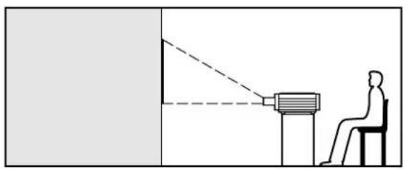
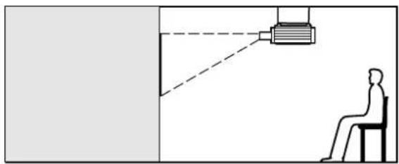
The projection method can be set in accordance with the way the projector has been installed. If the projected picture is upside-down or back-to-front, change the projection method while referring to illustrations A to D below.
A : Front-floor projection (FRONT-F)
natural_image
Diagram showing a person seated at a desk observing a projector mounted on a stand, with no text or symbols present.B : Rear-ceiling projection (REAR-C)

natural_image
Diagram showing a person seated in a chair facing a projector screen, with no text or symbols present.C : Rear-floor projection (REAR-F) D :

natural_image
Diagram showing a projector projecting onto a screen to a seated person (no text or symbols present)Front-ceiling projection (FRONT-C)
natural_image
Simple line drawing of a person sitting on a chair facing a wall-mounted device, no text or symbols presentSet the projection method by displaying on-screen displays using the control buttons on the remote control unit or the projector operating panel.
Setting procedure

① Press the MENU button. ... The MENU screen will be displayed.
② Press the UP(▲and DOWN ( )arrow buttons to select OPTION.
- The text colour of a selected item will change.
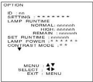
③ Press the ENTER button. ... The OPTION screen will be displayed.
④ Press the UP(▲and DOWN ( ) ▼row buttons to select SETTING.
⑤ Press the LEFT (◀) and RIGHT (▶) arrow buttons to select the projection method.
- The display and the projection method will change as shown below each time the LEFT ( ) or RIGHT ( ) arrow button is pressed.

flowchart
graph LR
    A["FRONT-F"] <--> B["REAR-C"]
    B <--> C["REAR-F"]
    C <--> D["FRONT-C"]
    D --> A
⑥ Press the MENU button twice.
- The on-screen display will disappear and the screen will return to the normal state.
Adjusting the lens
Adjusting the focus
Adjustment procedure

①Press the LENS button. ... The LENS screen will be displayed.
② Use the control level buttons (+ and -) to adjust the focus to the correct setting.
- Initial pressing of these buttons will allow fine adjustment. Pressing and holding these buttons will allow the slow mode for the first six seconds and then the fast mode.
③Press the MENU button.
- The on-screen display will disappear and the screen will return to the normal state.
Note : After the zoom adjustment of a zoom lens(sold separately), adjust the focus.
Adjusting the lens position (optical shift)
Adjustment procedure

①Press the LENS button. ... The LENS screen will be displayed.
②Use the (UP, DOWN, LEFT and RIGHT (▲, ▼ and ▶) buttons to adjust the lens position so that the centre of the picture is in the centre of the screen.
- Initial pressing of these buttons will allow fine adjustment. Pressing and holding these buttons will allow the slow mode for the first six seconds and then the fast mode.
③Press the MENU button to return the screen to the normal state.
- The following procedure can also be used in lens adjustment mode.

①Press the MENU button. ... The MENU screen will be displayed.
②Press the UP(▲and DOWN ( )arrow buttons to select LENS.
③Press the ENTER button. ... The LENS screen will be displayed.

• After the display of the LENS screen, follow the above procedure.
- For details on the adjustment range after lens positioning, refer to the next page.
Caution!
- Do not reach for the openings beside the optical lens, during horizontal or vertical movements of the lens there is a injury hazard.
Adjustment range after lens position (optical shift)
Adjustment range after lens positioning is as follows:
※The numbers in brackets are the dimensions when the ET-D95LE9 lens is being used.
Floor projection for PT-D9510E

Floor projection for PT-D9610E

Ceiling projection for PT-D9510E
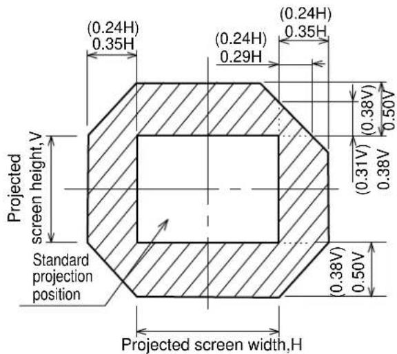
Ceiling projection for PT-D9610E

Installing the input module
Obtain the required input modules (sold separately) beforehand in accordance with the system input signal.
- Types of input module (sold separately)
| Input signal | Module No. | Input signal level |
| RGB/YPbPr/YCbCr signal | ET-MD95RGB | Video/Sync. signal input impedance: 75 /1 k R/ P_RC , B/ P_BC_b : 0.7 V [p-p] or 1.0 V [p-p] with BETACAM inputG/Y 0.7 V [p-p](1.0 V [p-p]when SYNC ON G/Y signal is input)Composite sync/Separate sync: 0.6 V [p-p]-4.0 V [p-p]with 75 , TTL level with 1 k Analogue RGB input signalf _H : 15 kHz—100 kHz, fV: 24 Hz—120 Hz,dot clock frequency: 20 MHz—162 MHzColour difference input signalApplicable formats: 480i, 576i, 480p, 720/60p,1080/60i(1035/60i)1080/50i, 1080/30p,1080/25p, 1080/24p, 1080/24sF |
| Video signal | ET-MD95VM2 | Video / Y: 1.0 V [p-p], C : 0.286 V [p-p] Cr / C _b : 0.7 V [p-p], Impedance: 75 |
| Serial digital signal | ET-MD95SD1 | Conforming to SMPTE259M |
| Serial digital signal | ET-MD95SD2 | Conforming to SMPTE259M/SMPTE294M |
| HD Serial digital signal | ET-MD95SD3 | Conforming to SMPTE292M |
| SVGA,XGA,SXGA signals | ET-MD95T | Conforming to TMDS |
- Input slot numbers

The bays (slots) in which the input modules are inserted are numbered 1, 2 and 3 in order starting from the top, as shown in the illustration at left.
The slots can be used in any order, and the same type of input module can be inserted into more than one slot at the same time. In addition, the projector will automatically detect which input module has been inserted into which slot.
It is necessary to select VIDEO or Y/C input and adjust the input signal after the input module has been inserted.
NOTE
- The signal sources connected to the input modules can each be selected by specifying the respective slot number using the input select buttons on the remote control unit or the projector operating panel. For details on selecting the input source refer to page 40.
- Modules other than the optional specified ones cannot be inserted into the slots 1, 2, and 3.
Installing the input modules
Disconnect the power supply from the projector before installing any of the input modules.
Installation procedure
① Remove the two screws which are holding the slot cover where the input module is to be installed, and then remove the slot cover.
② Fit the input module into the slot rails, and then push the input module in until it is seated in the connector, while being careful not to bump any of the module components.
③ Tighten the two screws to secure module in place.
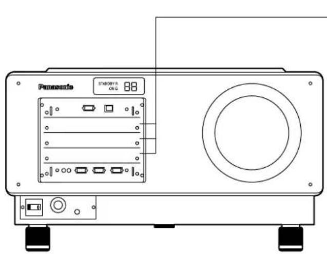
① Remove the slot cover
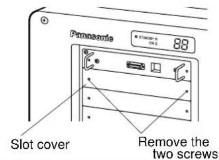
② Insert the input module

③ Secure the input module
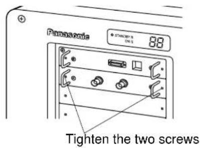
④ Register input signal
- With this equipment, it is necessary to store the input signal after installing the input module. (Refer to pages 42 and 43 for details on registering input signals.)
NOTE
- Up to three input modules can be installed.
- Do not remove any of the covers on spare slots where no input module has been installed.
- Be sure to install input modules in the slot 1, slot 2 and slot 3 positions.
Connecting the input module signal source
When setting up the projector, you will need to connect the signal source to an input module according to the type of signal being input.
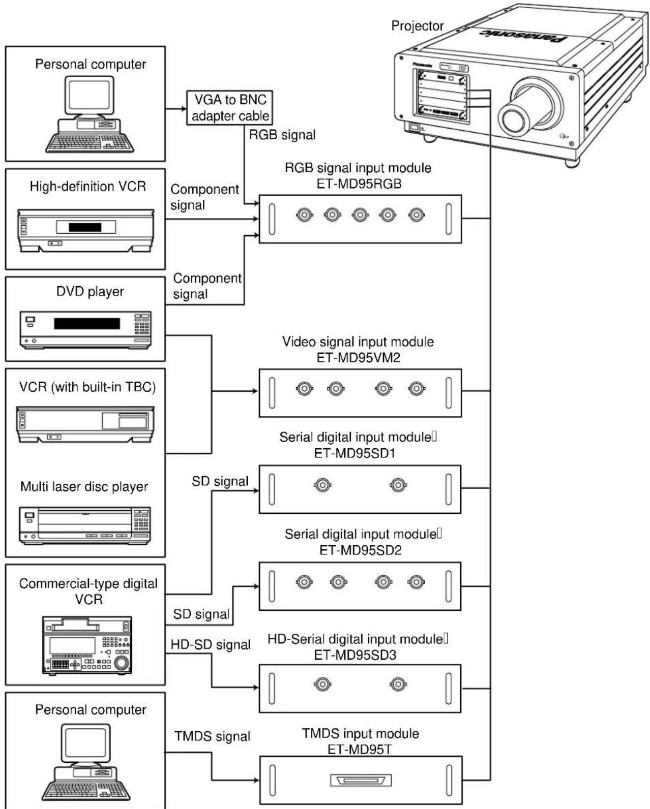
flowchart
graph TD
    A["Personal computer"] --> B["VGA to BNC adapter cable"]
    B --> C["RGB signal"]
    C --> D["RGB signal input module ET-MD95RGB"]
    E["High-definition VCR"] --> F["Component signal"]
    F --> G["Video signal input module ET-MD95VM2"]
    H["DVD player"] --> I["Component signal"]
    I --> G
    J["VCR (with built-in TBC)"] --> K["SD signal"]
    K --> L["Serial digital input module ET-MD95SD1"]
    M["Multi laser disc player"] --> N["SD signal"]
    N --> O["Serial digital input module ET-MD95SD2"]
    P["Commercial-type digital VCR"] --> Q["SD signal"]
    Q --> R["HD-Serial digital input module ET-MD95SD3"]
    S["Personal computer"] --> T["TMDS signal"]
    T --> U["TMDS input module ET-MD95T"]
    G --> V["Projector"]
    O --> V
    R --> V
Connecting the signal source to the input module for analogue RGB signals
If using the input module for analogue RGB signals in order to connect the projector to a personal computer, you will also need to use a separate interface (D-SUB → BNC) cable.
1. Connecting an analogue RGB signal source
RGB signal input module (sold separately)
ET-MD95RGB

flowchart
graph TD
    A["RGB Module ET-MD98RGB"] -->|R/P_R| B["D-SUB→BNC"]
    A -->|G/Y| B
    A -->|B/P_B| B
    A -->|H/H·V| B
    A -->|V| B
    B --> C["Personal computer"]
    C --> D["CAUTION: Ternary synchronization signals H/H·V and V terminals. Do not input synchronization signal terminals when SYNC ON GREEN ("C" means "composite sync" in)"]
CAUTION:
- Ternary synchronization signals cannot be input to the H/H·V and V terminals.
- Do not input synchronization signals to the H/H·V and V terminals when SYNC ON GREEN signals are being input. ("C" means "composite sync" in H/H·V.)
2. Connecting a component signal source
RGB signal input module (sold separately)
ET-MD95RGB
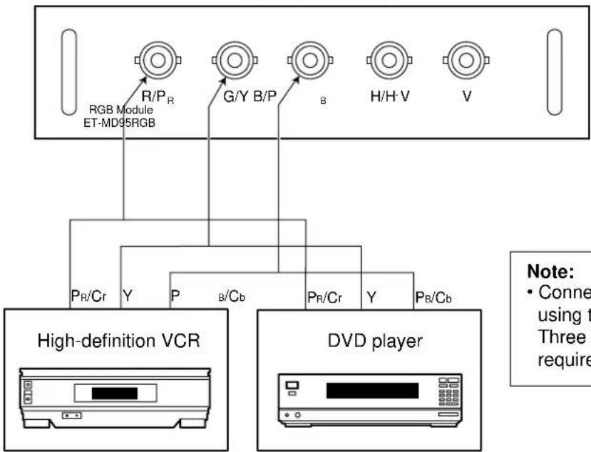
flowchart
graph TD
    A["RGB Module ET-MD95RGB"] --> B["R/P_R"]
    A --> C["G/Y B/P"]
    A --> D["B"]
    A --> E["H/H·V"]
    A --> F["V"]
    B --> G["P_R/Cr Y"]
    C --> H["P B/Cb"]
    D --> I["P_R/Cr Y"]
    E --> J["P_B/Cb"]
    G --> K["High-definition VCR"]
    H --> K
    I --> K
    J --> K
    K --> L["DVD player"]
    note right of L: Note: • Conne using t Three require
Note:
- Connect either the VCR or DVD player using three BNC cable.
Three BNC-to-RCA adaptors may be required at the DVD player.
Analogue RGB signals that can be input
The table below lists the different types of analogue RGB signals that can be input.
If a signal which differs greatly from any of the types listed below is input, the picture image may not be displayed correctly, or black background may be displayed.
| Display mode name Signal data | |||
| No. of dots Horizontal scanning frequency(kHz) Vertical scanning frequency(Hz) | |||
| VGA400 | 640×400 24.8 | 56.4 | |
| 640×400 31.5 | 70.1 | ||
| VGA480 640× | 640×480 31.5 | 59.9 | |
| 640×480 35.0 | 66.7 | ||
| 480 37.9 72.8 | |||
| 640×480 37.5 | 75.0 | ||
| 640×480 43.3 | 85.0 | ||
| SVGA 800×600 37.9 60.3 | |||
| 800×600 32.1 | 51.0 | ||
| 800×600 35.2 | 56.3 | ||
| 800×600 48.1 | 72.1 | ||
| 800×600 46.9 | 78.0 | ||
| 800×600 53.7 | 85.1 | ||
| XGA 1 024× | 1 024×768 48 | 4 60.0 | |
| 1 024×768 56 | 5 70.1 | ||
| 1 024×768 60 | 0 75.0 | ||
| 768 65.5 81.6 | |||
| 1 024×768 68 | 7 85.0 | ||
| 1 024×768i 35 | 5 86.8 | ||
| 1 024×768 80 | 7 100.8 | ||
| 1 024×768 94 | 0 120.0 | ||
| MXGA 1 152 | 1 152×864 63 | 9 70.0 | |
| 1 152×864 67 | 5 75.0 | ||
| ×864 77.1 85.0 | |||
| 1 120×750 50 | 1 60.1 | ||
| 1 120×750i 32 | 6 80.0 | ||
| SXGA 1 280× | 1 280×1 024 52 | 4 50.0 | |
| 1 280×1 024 64 | 0 60.0 | ||
| 1 280×1 024 72 | 4 66.3 | ||
| ×1 024 78.2 71.7 | |||
| 1 280×1 024 80 | 0 75.0 | ||
| 1 280×1 024i 46 | 2 86.0 | ||
| 1 280×1 024i 47 | 6 88.9 | ||
| MAC16 832× | 624 49.7 74.6 | ||
| MAC21 | 1 152×870 68 | 6 75.0 | |
| HDTV | 960×1 035i 33 | 8 60.0 | |
| UXGA | 1 600×1 200 75 | 0 60.0 | |
Note: • The display resolution of this projector is 1 024 x 768 dots(PT-D9510E)/1 280 x 1 024 dots(PT-D9610E). If the display resolution indicated in the above data exceeds this resolution, the resolution will be converted to 1 024 x 768 dots(PT-D9510E)/1 280 x 1 024 dots(PT-D9610E).
1. Connecting a video signal source
Video signal input module (sold separately)
ET-MD95VM2

flowchart
graph TD
    A["Video Module ET-MD95VM2"] -->|LINE/Cr IN| B["Luminance signal"]
    C["Video module"] -->|LINE OUT| B
    D["Y IN"] -->|C/Cb IN| E["S terminal → BNC"]
    F["Video signal"] --> B
    G["Video signal"] --> B
    H["Monitor TV"] --> I["(Purchase an S-VIDEO-to-BNC Adaptor cable locally)"]
    J["DVD player VCR (with built-in TBC)"] --> K["Multi laser disc player"]
- Switching between LINE input and Y/C input is carried out by toggling the INPUT button.
(Example) If the ET-MD95VM2 is inserted in slot 1 the selection will change as follows each time the INPUT 1 button on the remote control unit (or the INPUT button on the projector operating panel) is pressed.
LINE input → Y/C input
- If connecting a VCR, be sure to use one which has a built-in TBC.
- If applying a signal with s nonstandard burst signal, the picture may become unstable.
In this case, connect a time base corrector between this module and its signal source.
Connecting the signal source to the input module for video signals
2. Connecting a component signal source

- For details of composite and component signal switching, see ET-MD95VM2 (sold separately) signal switching on page 41.
Connecting the signal source to the input module for TMDS signals
TMDS input module (sold separately)
ET-MD95T

flowchart
graph TD
    A["TMDS Module ET-MD95T"] --> B["TMDS"]
    B --> C["Personal computer with TMDS output"]
    D["MDR26PIN"] --> B
    E["TMDS signal"] --> B
- This input module is for use with personal computers which are equipped with a TMDS output connector.
- The connector is a MDR 26-pin connector.
- The cable used should not be longer than 7 m / 22.96 feet( Recommend length : 5 m / 16.4 feet). If a cable which is longer than 7 m (22.96 feet) is used, signal conditioning amplifier should also be used.
- Before connecting the cable, check to make sure that the projector and PC are turned off. If cable connection is attempted with the projector and/or PC turned on, the PC may be damaged.
- Concerning a connecting cable used for this module, because its characteristic impedance can affect the picture performance, consult a Panasonic sales company.
Connecting the signal source to the input module for serial digital signals
Serial digital input module(sold separately)
ET-MD95SD1 (for 480i/576i)

- Use an input module which correctly matches the input signal type.
- The SYSTEM SELECTOR button can be used to toggle between different formats when using input modules that can handle two different signals with different specifications. The current signal format can be checked by looking at the on-screen display.
Connecting the signal source to the input module for serial digital signals
- 480p dual link (4:2:2p): 59.94 Hz progressive scan with 720 by 483 active lines at 270 Mbps, complying with the SMPTE294M Standard
Serial digital input module(sold separately)
ET-MD95SD2 (for 480p/480i/576i)

flowchart
graph TD
    A["480p Module ET-MD95SD2"] --> B["MAIN IN"]
    A --> C["MAIN OUT"]
    A --> D["SUB IN"]
    A --> E["SUB OUT"]
    B --> F["SD signal"]
    C --> G["SD signal output (Active through)"]
    D --> H["MAIN (Link-A)"]
    E --> I["SUB (Link-B)"]
    F --> J["Professional-type digital VCR"]
    G --> J
    H --> J
    I --> J
Connecting the signal source to the input module for serial digital signals
- 1) 480p single link (4:2:0p): 59.94 Hz progressive scan with 720 by 483 active lines at 360 Mbps, complying with the SMPTE294M Standard
2) 480i (4:2:2): 59.94 Hz interlace scan with 525 lines at 270 Mbps, complying with the SMPTE294M Standard
3) 576i (4:2:2): 50 Hz interlace scan with 625 lines at 270 Mbps, complying with the SMPTE294M Standard
Serial digital input module(sold separately)
ET-MD95SD2 (for 480p/480i/576i)

- Use an input module which correctly matches the input signal type.
- Input modules that accommodate the 4 video signal formats described above can be switched from one to another with the SYSTEM SELECTOR button that cycles through those signal formats. The selected input signal is indicated by an OSD message that automatically goes off.
- The SYSTEM SELECTOR should normally be set in the AUTO position.
- The automatic scan format identification logic may malfunction if signal connections other than those described above are employed or an unstable video signal is applied. In such an event, use the SYSTEM SELECTOR button to select the scan format that matches the video signal format applied.
- To ensure correct video signal transmission, use 3C2W or better than 3C2W cables for video interconnections (e.g., 3C2W, 3CFB, 4CFB, 5C2W, 5CFTX, 7CFB, etc.).
Connecting the signal source to the input module for serial digital signals
Serial digital input module(sold separately)
ET-MD95SD3 (for HD SDI)
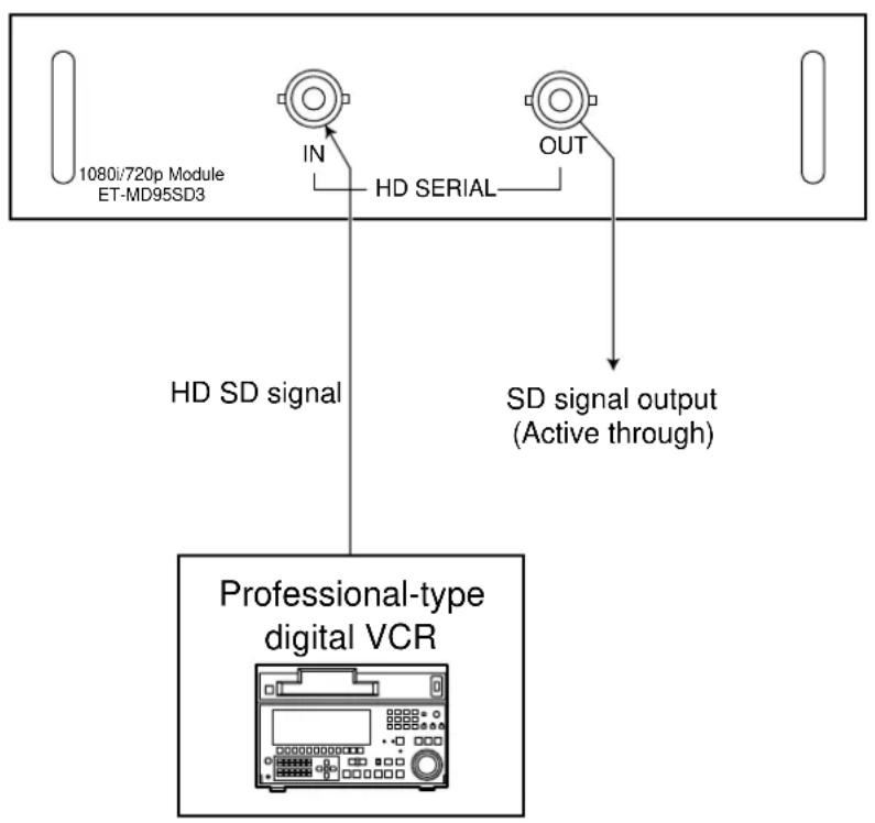
flowchart
graph TD
    A["1080i/720p Module ET-MD95SD3"] -->|IN| B["HD SERIAL"]
    B --> C["Professional-type digital VCR"]
    B --> D["SD signal output (Active through)"]
- Use an input module which correctly matches the input signal type.
- Input modules that accommodate 8 video signal formats (14 scan formats) (SMPTE292M) can be switched from one to another with the SYSTEM SELECTOR switch that cycles through those signal formats. The selected input signal is indicated by an OSD message that automatically goes off.

flowchart
graph TD
    A["AUTO"] --> B["1080/60i"]
    B --> C["1035/60i"]
    C --> D["720/60p"]
    D --> E["1080/24p"]
    E --> F["1080/50i"]
    F --> G["1080/30p"]
    G --> H["1080/25p"]
    H --> I["1080/24sF"]
    I --> J["AUTO"]
- The SYSTEM SELECTOR should normally be set in the AUTO position.
- The automatic scan format identification logic may malfunction if signal connections other than those described above are employed or an unstable video signal is applied. In such an event, use the SYSTEM SELECTOR button to select the scan format that matches the video signal format applied.
- To ensure correct video signal transmission, use 5CFB or better than 5CFB cables for video interconnections (e.g., 5CFB, 5CFTX, 7CFB, etc.).
Selecting the input signal
- The following remote control unit buttons and the INPUT button on the projector operating panel can be used to switch between different input sources.

flowchart
graph TD
    A["Remote control unit"] --> B["Projector"]
    B --> C["INPUT"]
    C --> D["OR"]
    D --> E["OR"]
    style A fill:#f9f,stroke:#333
    style B fill:#ccf,stroke:#333
    style C fill:#cfc,stroke:#333
    style D fill:#fcc,stroke:#333
    style E fill:#ffc,stroke:#333
- The input source can be changed in the order RGB INPUT 1 INPUT 2 INPUT 3 each time the INPUT button on the projector operating panel is pressed.
NOTE
- When using the video signal input module (ET-MD95VM2), the input source will toggle between LINE and Y/C input each time the above input selection buttons are pressed.
(Example) If the ET-MD95VM2 has been installed to slot 1.
When INPUT 1 of remote control (or INPUT button the projector operating panel) is pressed, LINE input will be selected, and when it is pressed once more, Y/C input will be selected.
Selecting the system format
- When the SYSTEM SELECTOR button on the remote control unit or the projector operating panel is pressed, the signal format will change as shown below depending on which input module is installed.
RGB signal input module ET-MD95RGB
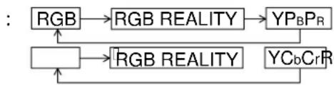
flowchart
graph TD
    A["RGB"] --> B["RGB REALITY"]
    B --> C["YP_B P_R"]
    A --> D["RGB REALITY"]
    D --> E["YC_b Cr R"]
- When 720p or 1080i signals are input
BWhen 480i or 576i or 480p signals are input
Video signal input module ET-MD95VM2
- When set at AUTO1
- When set at AUTO2
- When set at YCbCr
Serial digital input module
The SYSTEM SELECTOR button will not function for signals other than the above.

flowchart
graph LR
    A["AUTO1"] --> B["NTSC"]
    B --> C["PAL"]
    C --> D["SECAM"]
    D --> E["NTSC4.43"]
    E --> F["PAL60"]
    F --> A


- For details of the AUTO1, AUTO2, or YCbCr settings, see page 41.
- If you press the Standard (STD) button while system format is being switched by SYSTEM SELECTOR button, selection will return to AUTO1, AUTO2, or AUTO.
ET-MD95SD1 : AUTO → 480i → 576i
ET-MD95SD2 : AUTO → 480p → 480i → 576i

flowchart
graph TD
    A["AUTO"] --> B["1080/60i"]
    B --> C["1035/60i"]
    C --> D["720/60p"]
    D --> E["1080/24p"]
    E --> F["1080/50i"]
    F --> G["1080/30p"]
    G --> H["1080/25p"]
    H --> I["1080/24sF"]
    I --> J["AUTO"]
NOTE
- "480i" means a total of 525 lines, interlaced, and "576i" means 625 lines, interlaced, when the lines hidden by vertical blanking are counted.
Selecting the signal of ET-MD95VM2(sold separately)
When using the projector with the optional ET-MD95VM2 Video Input Module, select the appropriate video signal format that matches the video equipment you are using.
Setting procedure

① Press the MENU button. ... The MENU screen will be displayed. ② Press the UP (▲ and DOWN ( ) ▼row buttons to select OPTION.

③Press the ENTER button. ... The OPTION screen will be displayed. ④Press the UP (▲and DOWN ( ) ▼row buttons to select VIDEO MODULE SETTING.

⑤Press the ENTER button. ... The VIDEO MODULE SETTING screen will be displayed. ⑥Press the UP (▲ and DOWN ( ) ▼row buttons to select the desired INPUT MODULE. ⑦Press the UP (▲ and DOWN ( ) ▼row buttons to select the input signal system and press the UP (▲ and DOWN ( ) ▼row buttons to select input signal format "LINE or Y/C" or "YCbCr". •The selected signal format will be displayed. (The picture may be distorted while the signal format is being switched.) ⑧If chose "LINE or Y/C" in step ⑦ above, press the UP (▲) and DOWN (▼arrow buttons to select the video system and press the LEFT ( ) ◀ and LIGHT ( ▶) arrow buttons to select the "AUTO1" or "AUTO2 " •The selected signal format will be displayed. (The picture may be distorted while the signal format is being switched.) ⑨Press the MENU button 3 times consecutively. •The OSD information will go off.
Registering input signal data
Because the projector has no factory pre-set data of input signals, be sure to register input signal data before first use.
NOTE
- Up to 64 different input signals can be registered.
- Input a signal according to an input module installed on the projector and register the signal data.
Registration new signal
- If a new signal is input and MENU key of the remote control unit or projector operating panel buttons are pressed, the new signal registration screen shown below will be displayed. The registration procedure is given below.
Registration procedure

① Press the MENU button. ... The NEW SIGNAL INPUT screen will be displayed.
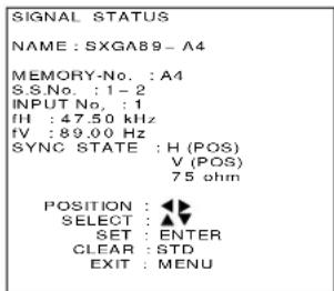
(Displayed contents is an example)
②Press the ENTER button. ... The SIGNAL STATUS screen will be displayed.
NOTE
- Parameters such as the memory number, signal selector input number, slot input number, type of input signal, frequency, and synchronizing signal are identified and displayed automatically.
- The memory numbers are from A1 to H8.(Each from A to H has eight memory numbers each.)
The lowest number of available memory numbers is displayed automatically. If there is no available memory number, follow the overwriting procedure on the next page. - For the registration name (NAME), the signal name and memory number are displayed automatically.
③ When using the original name displayed automatically on the screen without change, press the ENTER button.
- The registration is complete and the display will return to the MENU screen. When changing the original name, press LEFT(▲and RIGHT ( ) ▶row buttons to select a letter or number and then press the UP (▲and DOWN ( ) ▶row buttons to enter the selected letter or number. (If clearing the name change, press the STD button.)
After changing the name, press the ENTER button.
- The registration of the new name is complete and the display will return to the MENU screen.
NOTE
- If the MENU button is pressed instead of the ENTER button, the original name will be registered instead of the new name.
When the memory does not allow new signal registration because it is full
- When a total of 64 signals has already been registered and the memory is full, inputting a new signal and pressing the MENU button on the remote control unit or the projector operating panel will display the overwriting registration screen below. In this case, to register the new data, an existing signal will be cleared and overwriting with the new data.
Overwriting registration procedure

①Press the MENU button. ... The overwriting registration screen will be displayed.

②Press the ENTER button. ... The SIGNAL LIST screen will be displayed.
- The memory numbers are from A1 to H8. (64 type of memory numbers, each from A to H has eight memory numbers each.)
③Press the UP (and DOWN () Arrow buttons to select the signal to be cleared.

④ Press the ENTER button. ... The SIGNAL STATUS screen will be displayed.
- If not clearing the existing signal, press the MENU button to return the display to the SIGNAL LIST screen.

⑤ Press the ENTER button.
- The clearing operation is complete and the SIGNAL STATUS screen will be displayed. The contents of the new signal will be displayed for each item.
For the remainder of this registration procedure, follow ☑ on the previous page.
Sub-memory
This equipment has a sub memory function which enables storage of multiple image adjustment data sets, even when the signal is determined to be the same due to the frequency and form of the synchronization signal source. Use this when image adjustment (like aspect switching or white balance) is necessary due to the same signal source.
The sub-memory contains all data which can be adjusted for each signal, such as the image aspect ratio and adjustment video data (brightness, contrast etc.)
Sub-memory storage
Sub-memory storage cannot be performed with a new signal. Be sure to perform signal storage. At the ordinary screen (where the menu is not displayed) press the arrow buttons (◀▶).
This will display a list of sub-memory storage contents for the current input signal.
The sub-memory storage check screen is displayed each time a numerical button (1 to 9) not displayed in the list is pressed.
Sub-memory is stored by pressing the ENTER button at this screen.

Sub-memory switching
At the ordinary screen (where the menu is not displayed) press the arrow buttons (◀▶). This will display a list of sub-memory storage contents for the current input signal. Sub-memory switching is performed by pressing the numerical buttons (1 to 9) displayed in the list.
Sub-memory delete
Pressing the STD button at the stored signal list (STATUS LIST) causes the currently selected sub-memory to be deleted.
When the basic screen is deleted, all sub-memory contents for that input signal are deleted.
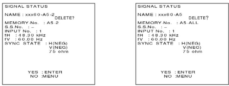
On-screen display
① Input switching/Signal switching
This displays the stored signal name for the STATUS screen during signal switching.
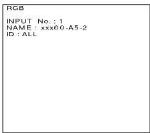
②Stored signal details

NOTE
Restrictions
- Up to 8 sub memories can be stored for each input signal. (Therefore there are 9 types in total, including the basic signal)
• A total of 32 sub memories can be stored in this equipment.
Sub-memory list
Input "7680" for the PASSWORD at the OPTION MENU.
This displays the list of signals stored as sub-memories.

Using the RGB REALITY mode
The RGB REALITY mode is a mode for converting RGB (primary color) input signals to component signals, performing high picture quality playback using image conversion processing specially for moving pictures.
You can choose the RGB mode best suited for the type of RGB signals you are using (refer to page 40):
RGB mode: Choose this mode when the RGB signal source is a PC or other computer-based device that focuses on still images.
RGB REALITY mode: Choose this mode when the RGB signal source is a scan converter or other video equipment that focuses on moving images.
The following lists the video signal formats compatible with the RGB Reality mode:
| Signal name | fH(kHz)/fV(Hz) | RGB mode | RGB REALITY mode | Remarks |
| 480i | 15.73/60 | |||
| 576i | 15.63/50 | |||
| 480p | 31.47/60 | |||
| 720/60p | 45.00/60 | |||
| 1035/60i | 33.75/60 | |||
| 1080/60i | 33.75/60 | |||
| 1080/24p | 27.00/24 | |||
| 1080/50i | 28.12/50 | |||
| 1080/30p | 33.75/30 | |||
| 1080/25p | 28.12/25 | |||
| 1080/24sF | 27.00/24 | |||
| Except above list | × | RGB mode only |
◎ : Compatible (factory default)
○ : Compatible (when you apply the RGB Reality mode to the signal formats marked with ○, select the signal format with the SYSTEM SELECTOR key, and then register it with the projector's memory.)
△ : These signal formats may not be compatible with RGB mode depending on signal conditions. Use the RGB Reality mode.
× : Not compatible
NOTE
- In the RGB REALITY mode, optimum adjustment values are pre-set, so it is not possible to automatically adjust the picture (pages 47 - 48) or the input signal resolution (page 49).
- When in RGB REALITY mode, all of the projector's adjustments provide the same functions as those for the YP_B P_R (or YC_b C_r ) input.
Adjusting the picture automatically
The automatic adjustment (AUTO SETUP) is a function to automatically adjust the resolution, clock phase, and picture position when inputting an analogue RGB signal consisting of dots like a computer signal. (The input of a moving picture signal or any signal other than analogue RGB signals cannot enable this function.)
It is recommendable for the automatic adjustment to input a picture signal including a brighter white box around the outside of the perimeter of a basic picture with clear, black-and-white characters and not including a halftone like a photograph or CG.
1. General automatic adjustment
Adjustment procedure

①Press the MENU button. ... The MENU screen will be displayed.
②Press the UP (▲and DOWN ( ) ▼row buttons to select AUTO SETUP.
③Press the ENTER button. ... This completes the automatic adjustment.
- “ NOW CALCULATION “ is displayed during automatic adjustment. Initial input display after automatic adjustment.
NOTE
- If automatic adjustment completes correctly, "COMPLETED" will be displayed. Even if this happens, there may still be some cases where the clock phase will not be correct. In such cases, adjust the clock phase manually.
- Adjust according to the following page when performing automatic adjustment of special signals and wide aspect (16:9 etc.) signals.
- If inputting a picture in which the edge of the screen is not known, or a dark picture, when starting the automatic adjustment the message “INCOMPLETED” will be displayed and the picture will not be adjusted automatically.
If this happens, you will need to manually adjust settings such as INPUT RESOLUTION, CLOCK PHASE and SHIFT.
- Some types of personal computer may not support automatic adjustment.
- Some types of synchronizing signals for C-SYNC and G-SYNC may not support the automatic adjustment.
- The picture may become distorted for approximately 4 seconds while automatic adjustment is being carried out, but this is normal.
- Adjustment is required for each of the input signals.
- Press MENU during automatic adjustment to cancel.
2. Special signal automatic adjustment
Adjustment procedure
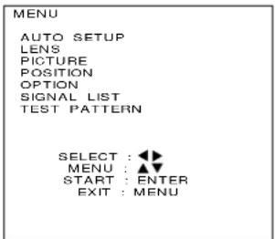
①Press the MENU button. ... The MENU screen will be displayed.

② Press the LEFT (◀) or RIGHT(▶) arrow buttons once time. ... The AUTO SETUP MENU screen will be displayed.
③ Press the LEFT (◀) and RIGHT(▶) arrow to switch to desired MODE.
•STANDARD ---- When receiving signals with an image aspect of 4:3 or 5:4
- WIDE ----When receiving signals with a wide image aspect of 16:9
- USER ---- When receiving a special horizontal resolution (number of horizontal display dots)
| Mode | Compatible Resolution |
| STANDARD | 640 x 400, 640 x 480, 800 x 600, 832 x 624, 960 x 720,1 024 x 768, 1 152 x 864, 1 152 x 870, 1 280 x 960,1 280 x 1 024, 1 600 x 1 200 |
| WIDE | 720 x 400, 848 x 480, 1 280 x 720, 1 120 x 750,1 376 x 768, 1 600 x 1 024 |
④When USER is selected for the mode, input the horizontal resolution (number of horizontal display dots) of the signal source at DISP DOTS using the control buttons (+, -).
⑤Press the ENTER button. ... This completes the automatic adjustment. - “ NOW CALCULATION “ is displayed during automatic adjustment. Initial input display after automatic adjustment.
Adjusting the picture manually
Signals which cannot be adjusted automatically should be adjusted manually. The following settings can be adjusted manually, and the respective adjustment procedures are given below.
- Input signal resolution data
- Clock phase
3.Picture position
Adjusting the input signal resolution
Adjustment procedure
MENU
AUTO SETUP
LENS
PICTURE
POSITION
OPTION
SIGNAL LIST
TEST PATTERN
MENU
SUB MENU : ENTER
EXIT : MENU
①Press the MENU button. ... The MENU screen will be displayed.
②Press the UP (▲and DOWN ( ) arrow buttons to select POSITION.
POSITION
SHIFT
SIZE
BLK
CLOCK PHASE
INPUT RESOLUTION
CLAMP POSITION
KEYSTONE
EDGE BLENDING
MENU
SUB MENU : ENTER
EXIT : MENU
③Press the ENTER button. ... The POSITION screen will be displayed.
④Press the UP (▲and DOWN ( ) ▼row buttons to select INPUT RESOLUTION.
NOTE
- The input resolution can be adjusted when an RGB signal has been input with the analogue RGB module (ET-MD95RGB)
INPUT RESOLUTION
TOTAL DOTS nppn
DISP DOTS nppn
TOTAL LINES nnnn
DISP LINES nnnn
DOTS CLOCK nnn. nnMHz
MENU
ADJUST
EXIT : MENU
⑤Press the ENTER button. ... The INPUT RESOLUTION screen will be displayed.
⑥Press the UP (▲and DOWN ( ) arrow buttons to select the desired item, and use the control level buttons (+ and -) to adjust.
TOTAL DOTS ---- Total number of horizontal dots
DISP DOTS ---- Actually displayed number of horizontal dots
TOTAL LINES ---- Total number of vertical lines
DISP LINES ---- Actually displayed number of vertical lines
Numeric values for each item are displayed according to the input signal. If vertical stripes or chipped areas appear on the screen, increase and decrease the displayed values to adjust the screen to its optimum state.
NOTE
- The input of an all-white picture does not allow the above stripes to appear.
- The picture may become distorted during the automatic adjustment, but this is normal.
Adjusting the clock phase
If a flicker or bleeding of the contour appears on the screen, adjust the clock phase to obtain an optimum picture.
Adjustment procedure
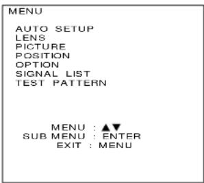
① Press the MENU button. ... The MENU screen will be displayed. ② Press the UP (▲ and DOWN ( ) ▼row buttons to select POSITION.

③Press the ENTER button. ... The POSITION screen will be displayed. ④Press the UP (▲ and DOWN ( ) ▼row buttons to select CLOCK PHASE.
NOTE
- The clock phase can be adjusted when an RGB signal has been input with the analogue RGB module (ET-MD95RGB)

⑤Press the ENTER button. ... The CLOCK PHASE screen will be displayed. ⑥Use the control level buttons (+ and -) to adjust the clock phase. • The adjustment values will change from 0 (min.) to 31 (max.).
NOTE • If the signal output from the personal computer is itself unstable, it may not be possible to obtain an optimum adjustment value.
- If the TOTAL DOTS setting is incorrect, it may not be possible to obtain an optimum adjustment value.
Adjusting the picture position
Adjustment procedure

①Press the MENU button. ... The MENU screen will be displayed. ②Press the UP (▲and DOWN ( ) arrow buttons to select POSITION.

③Press the ENTER button. ... The POSITION screen will be displayed. ④Press the UP ( ) and DOWN ( ) arrow buttons to select SHIFT.

⑤Press the ENTER button. ... The SHIFT screen will be displayed. ⑥Press the UP, DOWN, LEFT and RIGHT (▲, ▼and ▶) arrow buttons to adjust the picture position. ⑦Press the MENU button three times. • The on-screen display will disappear and the screen will return to the normal state.
< When adjusting the horizontal position
If the ▶ button is pressed, the picture moves to the right.
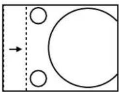
natural_image
Simple diagram with a rectangle, dashed vertical line, and circles inside (no text or symbols)If the ◀ button is pressed, the picture moves to the left.

natural_image
Simple geometric diagram with a circle and two circles inside a rectangle, separated by a dashed line (no text or symbols)< When adjusting the vertical position
If the ▲ button is pressed, the picture moves to the up.

natural_image
Simple diagram of a basketball court with two circles and an arrow indicating movement (no text or symbols)If the ▼ button is pressed, the picture moves to the down.
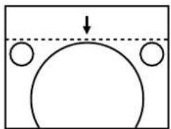
natural_image
Simple diagram showing a curved shape with two circles at the base, above a dashed line (no text or symbols)Adjusting the blanking
If picture noise appears at the perimeter of the screen or a picture extends off the screen a little, adjust the blanking to fine-tune the screen.
Adjustment procedure
MENU
AUTO SETUP
LENS
PICTURE
POSITION
OPTION
SIGNAL LIST TEST PATTERN

①Press the MENU button. ... The MENU screen will be displayed.
②Press the UP (▲ and DOWN ( ) arrow buttons to select POSITION.
POSITION
SHIFT
SIZE
BLK
CLOCK PHASE
INPUT RESOLUTION
CLAMP POSITION
KEYSTONE
EDGE BLENDING
MENU
SUB MENU

· ENTER
: MENU
③Press the ENTER button. ... The POSITION screen will be displayed.
④Press the UP (▲and DOWN ( ) arrow buttons to select BLK.
BLK:UPPER
UPPER : non
LOWER: non
LEFT : nnnn
RIGHT : nnnn
SELECT
ADJUST
EXIT

■
MENO
⑤Press the ENTER button. ... The BLK screen will be displayed.
⑥Press the control level buttons (+ and -) to select the desired BLK mode from those indicated below.
UPPER, LOWER, LEFT, RIGHT
⑦Press the UP (and DOWN() arrow buttons to adjust UPPER and LOWER, or Press the LEFT (and RIGHT() arrow buttons to adjust LEFT and RIGHT.
- The adjustment values will change from 0 (min.) to 511 (max.).
< When adjusting the upper blanking
If the ▲ button is pressed, the blanking portion moves upward. If the ▼ button is pressed, the blanking portion moves downward.

natural_image
Simple diagram of a basketball court with an arrow indicating upward motion and two circles below (no text or labels)< When adjusting the lower blanking
If the ▲ button is pressed, the picture moves upward. If the ▼ button is pressed, the blanking portion moves downward

natural_image
Simple diagram showing a semicircular shape above a hatched base with two circles, no text or symbols present.< When adjusting the left blanking
If the ▶ button is pressed, the picture moves to the right. If the ◀ button is pressed, the blanking portion moves ↓ to the left.

natural_image
Pure geometric diagram showing a rectangle with a circular hole and diagonal hatching, no text or symbols present.< When adjusting the right blanking
If the ▶ button is pressed, the blanking portion moves to the right. If the ◀ button is pressed, the blanking portion moves to the left.
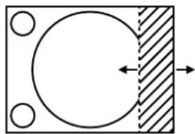
natural_image
Simple diagram showing a circle inside a rectangle with a diagonal hatched section and directional arrows (no text or symbols)Adjusting the clamp position
- If the black portions of the picture are fractured or tinged with green, adjust the clamp position its optimum state.
Adjustment procedure

① Press the MENU button. ... The MENU screen will be displayed.
② Press the UP (▲ and DOWN ( ) ▼row buttons to select POSITION.

③ Press the ENTER button. ... The POSITION screen will be displayed.
④ Press the UP (▲ and DOWN ( ) ▼row buttons to select CLAMP POSITION.
NOTE
- The clamp position can be adjusted when an RGB signal has been input with the analogue RGB module (ET-MD95RGB)

⑤ Press the ENTER button. ... The CLAMP POSITION screen will be displayed.
⑥ Press the LEFT ( ▶ and RIGHT ( ) ▶row buttons to adjust.
- The adjustment values will change from 0 (min.) to 254 (max.)
Optimum value for clamp position adjustment
- If the black sections are fractured
- If the black sections are tinged with green
→ The optimum value is when the fracturing of the black sections is at a minimum.
→ Optimum value is when the green portion turns black but is not smudged.
Picture mute function
The projector has a picture mute capability that allows you to put the image off instantaneously. To mute the image, press the PIC-MUTE button on the projector or remote control. To reset picture mute, press the PIC-MUTE button a second time.
Adjusting the keystone(Trapezoidal distortion)
- The KEYSTONE adjustment allows you to compensate for pictures' horizontal trapezoidal distortion. (Keystone adjustment can not carried out in built-in test pattern.)
Adjustment procedure

① Press the MENU button. ... The MENU screen will be displayed.
②Press the UP (▲and DOWN ( ) arrow buttons to select POSITION.

③Press the ENTER button. ... The POSITION screen will be displayed.
④ Press the UP (▲ and DOWN ( ) ▼row buttons to select KEYSTONE.

⑤ Press the ENTER button. ... KEYSTONE screen will be displayed.
⑥ Press the LEFT ( ) and RIGHT ( ) arrow buttons to correct horizontal keystone (trapezoidal distortion).
- The adjustment values will change from 0 (min.) to 200 (max.)
⑦ Press the UP (▲ and DOWN ( ) arrow buttons to adjust vertical linearity.
- The adjustment values will change from 0 (min.) to 255 (max.)
NOTE
- Adjust vertical linearity after adjusting horizontal keystone.
The variable range of V LINEARITY changes with the H KEYSTONE adjustment setting. - To reset H KEYSTONE and V LINEARITY to their respective factory default settings (H KEYSTONE:100 and V LINEARITY: 25), press the Standard (STD) button on the remote control.
- H KEYSTONE and V LINEARITY settings are reflected to other input signals as well.
- The keystone adjustment can compensate for trapezoidal distortion that corresponds to the projector's elevation angle (to the screen) to within ± 10^ .
- As indicated below, two types of modes can be selected for keystone correction of luminance-bandwidth-chrominance (YUV) signals (For the RGB system, there is only keystone correction using digital processing).
YUV KEYSTONE:REAL: The original images are preserved as they are after keystone compensation thanks to digital processing.
YUV KEYSTONE:BLANKING: Keystone correction is done with blanking, so part of the image information is lost, but there is no image degradation.
(In BLANKING mode, the adjustment range in blanking adjustment (page 52) is 0 to 255).
Press and hold the right arrow button ▶ until both sides of the frame become completely vertical. In case of overadjustment, use the left arrow button ◀ to step back.

YUV signals: Includes the Video Signal module, Digital Serial Signal module, analog YPBPR(YCbCr) input, and analog RGB input all placed in RGB REALITY mode.
Adjusting the picture to the desired setting
The following procedures can be used to adjust the picture to the desire appearance.
Adjustment procedure ... Adjusting the COLOUR setting

① Press the MENU button. ... The MENU screen will be displayed.
②Press the UP (▲and DOWN ( ) ▼row buttons to select PICTURE.

③ Press the ENTER button. ... The PICTURE screen will be displayed.
④ Press the UP (▲ and DOWN ( ) ▼row buttons to select COLOR.

⑤Press the ENTER button. ... The COLOR individual adjustment screen will be displayed.
⑥Use the control level buttons (+ and -) to adjust the COLOUR setting level.
*1. The functions of the LEFT (× and RIGHT ( ) ▶row buttons change depending on the adjustment item selected. Refer to the table below for details.
⑦If you would like to adjust the BRIGHT, CONTRAST and TINT settings, repeat steps ④, ⑤ and .
*2. If adjusting the BRIGHT and CONTRAST settings, the individual adjustment screens can be displayed by pressing the respective buttons on the remote control unit.
| Adjustment Item | Operation Adjustment Details | Adjustment Range | Remarks | |
| COLOR | Press the [+] button. | The colour becomes pastel. | Max. value 100 | |
| Press the [-] button. | The colour becomes more intense. | Min. value 0 | ||
| TINT | Press the [+] button. | Flesh tones become greenish. | Max. value 60 | |
| Press the [-] button. | Flesh tones become reddish. | Min. value 0 | ||
| BRIGHT | Press the [+] button. | The screen becomes brighter. | Max. value 63 | |
| Press the [-] button. | The screen becomes darker. | Min. value 0 | ||
| CONTRAST | Press the [+] button. | The bright areas become brighter. | Max. value 63 | |
| Press the [-] button. | The bright areas become darker. | Min. value 0 | ||
NOTE
- If approximately five seconds pass without any buttons being pressed while an individual adjustment screen is being displayed, the display will return to the PICTURE screen.
Adjusting the white balance
Adjustment procedure (Project a signal to be adjusted)
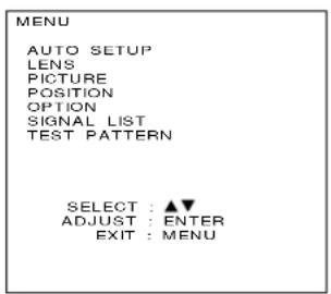
① Press the MENU button. ... The MENU screen will be displayed.
② Press the UP (▲ and DOWN ( ) ▼row buttons to select PICTURE.

③ Press the ENTER button. ... The PICTURE screen will be displayed.
④ Press the UP (▲and DOWN ( ) ▼row buttons to select COLOR TEMP.
⑤ Press the LEFT ( ) and RIGHT ( ) Arrow buttons to select the desired setting from those indicated below.
LOW, MID, HIGH, USER, DYNAMIC

⑥ Select USER in step ⑤
⑦ Press the ENTER button. ... The WHITE BALANCE screen will be displayed.
⑧ Press the UP (▲ and DOWN ( ) arrow buttons to select either R, G or B.
⑨ Use the control level buttons (+ and -) to adjust the setting level.
| Adjustment Item | Operation Adjustment Details | Adjustment Range | |
| R (Red) | Press the [+] button. | The red component becomes stronger. | Max. value 255Min. value 0 |
| Press the [-] button. | The red component becomes weaker. | ||
| G (Green) | Press the [+] button. | The green component becomes stronger. | |
| Press the [-] button. | The green component becomes weaker. | ||
| B (Blue) | Press the [+] button. | The blue component becomes stronger. | |
| Press the [-] button. | The blue component becomes weaker. | ||
NOTE
- If these adjustments are not made correctly, none of the colours will be reproduced correctly.
- If you make an error in adjustment so that the colours do not match correctly, press the STD button while one of the individual adjustment screens is being displayed. Only the item being displayed will be reset to the factory pre-settings.
- The projection of a built-in test pattern (Refer to page 65.) does not allow the white balance adjustment. Be sure to project an external input signal for this adjustment.
Adjusting the picture quality
The following procedures can be used to adjust the picture quality to the desired setting.
Adjustment procedure

① Press the MENU button. ... The MENU screen will be displayed. ② Press the UP (▲ and DOWN ( ) ▼row buttons to select PICTURE.
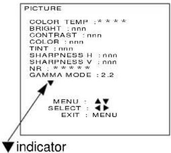
③Press the ENTER button. ... The PICTURE screen will be displayed.
NOTE
- If a or indicator is shown at the bottom or top of the adjustment items list in the PICTURE window, it indicates that the remaining part of the list can be scrolled up or down in the window. Use the UP or DOWN arrow button (▲) to scroll the list.

④ Press the UP (▲ and DOWN ( ) ▶row buttons to step through the adjustment items list until you reach the target item. ⑤ Press the LEFT (▲ and RIGHT ( ) ▶row buttons to change the current setting. • For available adjustment items and settings, see the table on the next page.
| Adjustment Item | Operation | Adjustment Details |
| SHARPNESS H | Makes the horizontal contours sharper. | Nine steps from OFF to 8 (factory default : 2)A larger value causes a greater effect |
| SHARPNESS V | Makes the vertical contours sharper. | Four steps from OFF to 3 (factory default : 2)A larger value causes a greater effect |
| NR(Noise Reduction) | Selects the noise reduction effectiveness. | OFF: No correction1 : Weak2 : Medium (factory default)3 : StrongA larger value causes a greater effect |
| GAMMA MODE | Selects the gamma mode. | Two steps of 2.2 and 2.5 (factory default : 2.2) |
| FILTER | For the PT-D9510E, use this adjustment to select interpolation filter settings for signals other than XGA. For the PT-D9610E, use this adjustment to select interpolation filter settings for signals other than SXGA. | Five types from 0 to 4 (factory default : 2)0 : Gives priority to contrast.4 : Restricts the loss in picture information to a minimum. |
| FRAME RATE | Use this adjustment to choose the best frame rate conversion for minimum flicker on individual HDTV signal input. | 24p→60p / 24p→24p(factory default: 24p→60p)25p→50p / 25p→25p(factory default: 25p→50p)30p→60p / 30p→30p(factory default: 30p→60p)24sF→60p / 24sF→24p / 24sF→48i(factory default: 24sF→60p) |
| PAL CINEMA | Use this adjustment to further enhance vertical resolution when a 576i, 1 080/50i PAL (or SECAM) signal is applied. | OFF : No cinema processingAUTO : Auto detection (factory default)ON : Cinema processing (see the following notes) |
NOTE
- NR (noise reduction) settings cannot be adjusted for analogue RGB input and TMDS input.
- The FILTER adjustment is ineffective for XGA (1 024 x 768) mode on the PT-D9510E, or SXGA (1 280 x 1 024) mode on the PT-D9610E. It is also ineffective for any video input mode other than analogue RGB and TMDS modes, or if “THROUGH” is chosen for the SIZE mode (see page 60 and 61).
- Even with the above signal, adjustment is possible during keystone correction. Even with YUV type signals, adjustment is possible during REAL keystone correction.
- FRAME RATE is effective only for analogue RGB, HD serial, 1080/30p, 1080/25p, 1080/24p, and 1080/24sF video signal formats.
- PAL CINEMA is effective only for the 576i, 1 080/50i PAL (or SECAM) standard.
- PAL CINEMA will cause degraded picture quality (lowered vertical resolution) if used for signals other than those pulled down at a 2:2 ratio.
- For 480p, 480i or 576i scan format, SHARPNESS H defaults to 6.
Adjusting the picture size
Adjustment procedure
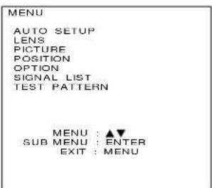
① Press the MENU button. ... The MENU screen will be displayed.
② Press the UP (▲ and DOWN ( ) ▼row buttons to select POSITION.

③Press the ENTER button. ... The POSITION screen will be displayed.
④Press the UP (▲and DOWN ( ) arrow buttons to select SIZE.

⑤Press the ENTER button. ... The SIZE screen will be displayed.
⑥Press the control level buttons (+ and -) to select the desired size mode from those indicated below.
DEFAULT, THROUGH, H-FIT, V-FIT, HV-FIT, ZOOM
- "4:3", "16:9" ---- Modes other than the analogue RGB or TMDS input allow the selection.
Size modes
DEFAULT . The input signal is projected with the aspect ratio unchanged.
THROUGH The input signal is projected with the resolution unchanged.
H-Fit..... The input signal is projected with all horizontal panel picture elements used. For signals with a aspect ratio which is vertically longer than 4:3(for the PT-D9510E)/5:4(for the PT-D9610E), the top and bottom edges of the picture are cropped.
V-Fit .... The input signal is projected with all vertical panel picture elements used. For signals with a aspect ratio which is horizontally longer than 4:3(for the PT-D9510E)/5:4(for the PT-D9610E), the left and right edges of the picture are cropped.
HV-Fit .... The input signal is converted to an aspect ratio of 4:3(for the PT-D9510E) / 5:4(for the PT-D9610E). For signals with an aspect ratio other than 4:3(for the PT-D9510E) / 5:4(for the PT-D9610E), circles in the picture become distorted, etc.
HV-Fit ..... The input signal is converted to an aspect ratio of 5:4. For signals with an aspect ratio other than 5:4, circles in the picture become distorted, etc.
ZOOM .... The enlargement ratio of the picture is changed. The enlargement ratio in both the horizontal and vertical directions can be changed to between 50 % and 999 %(except analogue RGB, TMDS input), between 75 % and 999 %(up to SXGA of analogue RGB, TMDS input), between 100 % and 999 %(UXGA of analogue RGB, TMDS input) with the top-left corner of the screen as the reference point.
4:3 ..... The input signal is projected with the aspect ratio 4:3.
16:9 ..... The input signal is projected with the aspect ratio 16:9.
- An overscan of 7 % is applied to all modes other than analogue RGB input and TMDS input.
• The 4:3 and 16:9 mode are only for YUV type signal input
Screen examples for different size settings (For PT-D9510E)
| INPUTPICTURESIZESETTING | 8:5(640×400) | 4:3(1152×864) | 5:4(1280×1024) |
| Default |  The picture is displayed at maximum size while maintaining the original aspect. The picture is displayed at maximum size while maintaining the original aspect. |  |  |
| Through |  |  |  |
| H-Fit |  |  |  |
| V-Fit |  |  |  |
| HV-Fit |  |  |  |
* If the picture extends outside the screen, the top-left corner is used as the reference point.
Screen examples for different size settings(For PT-D9610E)
| INPUT PICTURE SIZE SETTING | 8:5(640×400) | 4:3(1152×864) | 5:4(1280×1024) |
| Default |  The picture is displayed at maximum size while maintaining the original aspect. The picture is displayed at maximum size while maintaining the original aspect. |  |  |
| Through |  |  |  |
| H-Fit |  |  |  |
| V-Fit |  |  |  |
| HV-Fit |  |  |  |
* If the picture extends outside the screen, the top-left corner is used as the reference point.
Power up function
Power up function
The projector is provided with a power up function which allows the performance of the lamp to be utilized to the maximum level.
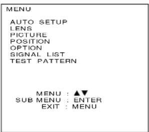
①Press the MENU button. ... The MENU screen will be displayed.
②Press the UP (▲and DOWN ( ) arrow buttons to select OPTION.
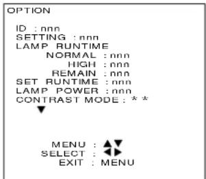
③Press the ENTER button. ... The OPTION screen will be displayed.
④Press the UP (▲and DOWN ( ) arrow buttons to select LAMP POWER.
⑤Press the LEFT ( ) and RIGHT ( ) ▶row buttons to select HIGH (power up) setting in LAMP POWER mode.
| Setting Mode |
| HIGH Power up mode |
| NORMAL Normal mode |
⑥Press the MENU button twice.
- The on-screen display will disappear and the screen will return to the normal state.
CAUTION
- Power up mode (HIGH) is cancelled when the power is turned off. Therefore, the mode will return to the normal usage mode (NORMAL) when the power is turned back on.
- When HIGH has been set in LAMP POWER mode, the lamp's useful life will be shorter compared to normal mode.
- Lamp power mode switching is effective only when the contrast mode is normal or high. It does not work when the contrast mode is super.
Contrast switching function
This equipment has 3 mode types for adjusting to the use environment.
Switching procedure

① Press the MENU button. ... The MENU screen will be displayed.
② Press the UP (▲ and DOWN ( ) arrow buttons to select OPTION.

③ Press the ENTER button. ... The OPTION screen will be displayed.
④ Press the UP (▲ and DOWN ( ) ▼row buttons to select CONTRAST MODE.
⑤ Press the LEFT (◀ and RIGHT ( ) ▶row buttons to select the mode.
| Mode | NORMAL | HIGH SUPER | |
| CONTRAST | Normal | Middle | Maximum |
| BRIGHTNESS | Maximum | Maximum | Normal |
⑥ Press the MENU button twice.
- The on-screen display will disappear and the screen will return to the normal state.
NOTE • In the SUPER mode, lamp service life is shorter than with other modes.
When inputting BETACAM with YCbCr 480i
When receiving 480i with analog component signal YCbCr input, it is possible to switch Cb, Cr input.
Switching procedure

①Press the MENU button. ... The MENU screen will be displayed.
②Press the UP (▲and DOWN ( ) ▼row buttons to select PICTURE.

③Press the ENTER button. ... The PICTURE screen will be displayed.
④Press the UP ( ▲ and DOWN ( ) arrow buttons to select FORMAT.
⑤Press the LEFT ( ) and RIGHT ( ) arrow buttons to switch signal format.
- Switching is done with the SMPTE and BETACAM toggle.
< Signal level>
| System | Y | Sync part | Cb,Cr |
| SMPTE | 700 mV | 300 mV | ± 350 mV |
| BETACAM | 714 mV | 286 mV ± 504 mV |
NOTE
- This function can be used only when input is done with an analog RGB input module (ET-MD95RGB).
- This function enables switching only when receiving 480i in YCbCr mode. Switching cannot be done in RGB REALITY mode, RGB mode, or when receiving signals other than 480i.
• The initial value is SMPTE.
Method of switching input impedance(signal level) for sync input
With analog RGB input, it is possible to switch the input impedance (signal level) of the sync signal. When connecting with equipment (like a signal selector) whose sync output impedance is 75 ohm, use 75 ohm, and when connection with equipment (like a PC video card) whose sync output is TTL, switch to TTL (HI-Z).
Switching procedure

①Press the MENU button. ... The MENU screen will be displayed.
②Press the UP (▲and DOWN ( ) arrow buttons to select OPTION.

③Press the ENTER button. ... The OPTION screen will be displayed.
④ Press the UP (▲ and DOWN ( ) ▼row buttons to select SYNC TERM.
⑤Press the LEFT ( ) and RIGHT ( ) arrow buttons to switch input impedance (signal level) of sync signal.
- Switching is done using the 75 ohm and TTL (HI-Z) toggle.
| SYNC TERM. | Signal Level | Input Impedance |
| 75 ohm | Amplitude:0.6 V [p-p]—4.0 V [p-p] | 75 Ω |
| TTL(HI-Z) | High level : more than 2.0 VLoe level : Less than 0.8 V | 1 kΩ |
NOTE
- This function can be used only when input is done with an analogue RGB input module (ET-MD95RGB).
- Use by switching for each input signal.
• The initial value is 75 ohm. - When this switching is performed, the CLOCK phase and image position may shift, so adjust again.
Displaying a test pattern
17 types of test pattern are built in. These test patterns can be used to check the various adjustment settings. Use the following procedure to display a test pattern.
NOTE
•These test patterns cannot reflect the adjustment results of various picture settings such as picture quality, positions, and sizes. Be sure to project an external input signal for various adjustments.
Operating procedure

①Press the MENU button. ... The MENU screen will be displayed.
②Press the UP (▲and DOWN ( ) arrow buttons to select TEST PATTERN.
③Press the LEFT ( ) and RIGHT ( ) Arrow buttons to select the required test pattern.
Test pattern display chart (LEFT and RIGHT arrow buttons)

flowchart
graph TD
    A["MENU screen + Input picture"] --> B["MENU screen + Full white"]
    B --> C["MENU screen + Full black"]
    C --> D["MENU screen + H-Gray scale"]
    D --> E["MENU screen + H-Gray scale (reversal)"]
    E --> F["MENU screen + V-Gray scale"]
    F --> G["MENU screen + V-Gray scale (reversal)"]
    G --> H["MENU screen + Crosshatch"]
    H --> I["MENU screen + Crosshatch"]
    I --> J["MENU screen + Flag (reversal)"]
    J --> K["MENU screen + Flag"]
    K --> L["MENU screen + Window (reversal)"]
    L --> M["MENU screen + Window"]
    M --> N["MENU screen + Focus"]
    N --> O["MENU screen + Colour bar"]
    O --> P["MENU screen + Dot (reversal)"]
    P --> Q["MENU screen + Dot"]
    Q --> R["MENU screen + Full white"]
    R --> S["MENU screen + Input picture"]
    S --> T["MENU screen + Focus"]
    T --> U["MENU screen + Convergence"]
    U --> V["MENU screen + Flag (reversal)"]
    V --> W["MENU screen + Flag"]
    W --> X["MENU screen + Window (reversal)"]
    X --> Y["MENU screen + Window"]
    Y --> Z["MENU screen + Focus"]
Displaying the projector settings
Display procedure

① Press the MENU button. ... The MENU screen will be displayed. ② Press the UP (▲ and DOWN ( ) ▼row buttons to select OPTION.

③Press the ENTER button. ... The OPTION screen will be displayed. ④Press the UP (▲and DOWN ( ) arrow buttons to select SYSTEM INFORMATION.

⑤ Press the ENTER button. ... The SYSTEM INFORMATION screen will be displayed.

Firmware version number Cumulative lamp usage time (normal mode) Cumulative lamp usage time (HIGH mode) Remaining lamp operating time (calculated in normal mode) Cumulative projector running time Internal temperature information Exhaust temperature information Data for module in slot RGB (RGB) Data for module in slot 1 (INPUT 1) Data for module in slot 2 (INPUT 2) Data for module in slot 3 (INPUT 3)
Adjusting the edge blending
The projector is equipped with a function to blend edges that may appear on the screen during multi-screen use.
Adjustment procedure

① Press the MENU button. ... The MENU screen will be displayed.
② Press the UP (▲ and DOWN ( ) ▼row buttons to select POSITION.
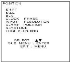
③ Press the ENTER button. ... The POSITION screen will be displayed.
④ Press the UP (▲and DOWN ( ) ▼row buttons to select EDGE BLENDING.
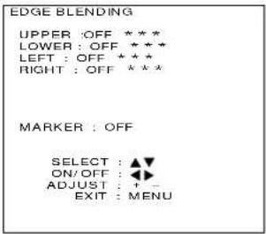
⑤Press the ENTER button. ... The EDGE BLENDING screen will be displayed.
⑥ Press the UP (▲ and DOWN ( ) ▼row buttons to select designate the area to blend.
- If blending the upper part: set UPPER to ON.
- If blending the lower part: set LOWER to ON.
- If blending the left part: set LEFT to ON.
- If blending the right part: set RIGHT to ON.
⑦Press the LEFT ( ) and RIGHT( ) ▶row buttons to turn ON and OFF.
⑧ Adjust the correction area using the control level buttons (+ and -).
• Used when displaying adjustment marker.
⑨Select MARKER using the UP (▲and DOWN ( ) arrow buttons.
⑩ Select ON and OFF using the LEFT (✗ and RIGHT( ) ▶row buttons.

NOTE
Adjustment marker
The image-positioning marker is displayed when the MARKER is turned ON.
A green line is displayed to the top and left of the screen, and a red line is displayed to the bottom and right of the screen. The position where the red and green lines overlap is the best position for combining projectors.
Caution:
Be sure to set the correction width to the same value for the two projectors to be combined. If projectors have different values, the best blending of edges cannot be achieved.
Adjusting the color matching
The projector is equipped with color matching adjustment functions to adjust colour balance when using several units in combination.
Adjustment procedure

①Press the MENU button. ... The MENU screen will be displayed.
②Press the UP (▲and DOWN ( ) ▼row buttons to select PICTURE.
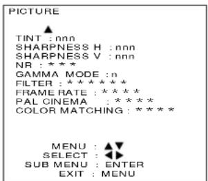
③Press the ENTER button. ... The PICTURE screen will be displayed.
④Press the UP ( ▲ and DOWN ( ) arrow buttons to select COLOR MATCHING.
⑤Press the LEFT (✗ and RIGHT( ) ▶row buttons to turn ON.

⑥Press the ENTER button. ... The COLOR MATCHING screen will be displayed.
⑦Press the UP ( ▲ and DOWN ( ) arrow buttons to select the colour to adjust.

⑧Press the ENTER button.
⑨Press the UP ( ) and DOWN ( ) arrow buttons to select compensating colour.
⑩Adjust the value using the control level buttons (+ and -).
NOTE
For adjusting
• Effects of altering the colour adjustment:
When altering the same colour correction as the colour adjustment: the luminance of the colour under adjustment changes.
When altering the RED colour correction: the RED component of the colour under adjustment increases or decreases.
When altering the GREEN colour correction: the GREEN component of the colour under adjustment increases or decreases.
When altering the BLUE colour correction: the BLUE component of the colour under adjustment increases or decreases.
- Adjustment requires skill and should be done only by service personnel or persons with sufficient knowledge of projectors.
- All adjustments can be reset to factory default settings using the STD (standard) button.
- Adjustment is valid only during COLOR TEMP USER and DYNAMIC. It is invalid during LOW, MID and HIGH.
Setting and specifying ID numbers
This projector is provided with an ID number function, so that if multiple projectors are being used together, the projectors can be controlled all at once or separately using a single remote control unit.
Because the factory pre-setting of the ID number is ALL, using only one projector do not require this setting.
Setting ID numbers
Setting procedure

①Press the MENU button. ... The MENU screen will be displayed.
②Press the UP(▲ and DOWN( ) ▼row buttons to select OPTION.

③Press the ENTER button. ... The OPTION screen will be displayed.
④ Press the LEFT(✗ and RIGHT( )arrow buttons to change the value.
(ALL, 1, 2, ..., 64)
⑤Press the MENU button twice. ... This completes the setting.
- The setting is complete. At that time, the on-screen display will disappear and the screen will return to the normal state.
NOTE
- The ID numbers can be set to ALL or to a number from 1 to 64.
- The ID number is set to ALL at the time of shipment from the factory.
- When setting ID numbers, the ID number of the remote control unit must match the ID number of the projector.
- All projectors which have had their ID numbers set to ALL will operate regardless of which number is specified when using the remote control unit or a personal computer to control the projectors. If the projector is connected to other projectors and its ID number is set to ALL, it will not be possible to control the projector separately from other projectors with different ID number settings.
Setting remote control unit ID numbers
When an ID number has been assigned for a projector, you then need to assign the same ID number as the projectors to be controlled to the remote control unit which is to be used to operate these projectors, otherwise the remote control unit cannot be used.
Because the factory pre-setting of the projector ID number is ALL, using only one projector requires the use of the ID ALL button on the remote control unit for this setting.
Setting method
Within 5 seconds of pressing the ID SELECT button, use the NEXT button to set the tens digit of the ID number which has been assigned to the projector, and then use the numeric buttons (0 to 9) to set the units digit.
However, if the ID ALL button is pressed, the remote control unit will operate the projector regardless of which ID number has been assigned to the projector.
- If the NEXT button or a numeric button is not pressed within 5 seconds of pressing the ID SELECT button, the ID number will return to the setting prior to when the ID SELECT button was pressed.
- Setting an ID number for the remote control unit can be carried out without needing the projector, so be careful not to press the ID SELECT button inadvertently.
- Once an ID number has been assigned to the remote control unit, that ID number will be stored in the remote control unit until it is again changed. However, if the remote control unit is left with flat batteries inside it, the ID number setting will be cleared. When the batteries are replaced, re-assign the same ID number to the remote control unit.
If you do not know the ID number assigned to the projector
If you do not know what ID number has been assigned to the projector, turn on the projector so that it is operating, and then press the ID SELECT button. The ID number will then be displayed on the screen as shown at right.
The ID number for the projector can be set to ALL or to a number from 1 to 64.
Using the RS-232C connectors
The projector is equipped with a D-SUB 9-pin RS-232C input connector and RS-232C output connector which allow the projector to be controlled externally. These connectors conform to RS-232C specifications, and can be used by a computer which conforms to either RS-232 or RS-232C specifications.
- Set the communication parameters below according to a computer to be connected. To connect the computer, use a straight cable and connect it to the RS-232C IN connector.
- Communication parameters
•Baud rate (bps) : 1 200/2 400/4 800/9 600/19 200/38 400/76 800
102 400/122 800/153 600/204 800/307 200
•Parity : ODD/EVEN/NONE
•VPS system : MASTER/SLAVE
- Start & stop bits : 1 bit (fixed)
•Character length : 8 bit (fixed)
•X parameter/S parameter : None
- Synchronization : Start-stop asynchronous
MASTER: Returns a command in response to ID ALL.
SLAVE: Returns no command in response to ID ALL.
- GROUP : A\~Z / - (no GROUP specification)
: MASTER/SLAVE
MASTER:Transfers (returns) the command corresponding to the group.
SLAVE: Does not transfers (return) the command corresponding to the group.
- BAUD RATE, PARITY, VPS SYSTEM, and GROUP are reconfigurable parameters (see the page 73):
NOTE
- This unit switches to energy-saving mode when in standby to reduce energy consumption.
When turning the power ON from standby mode, send the POWER ON (3Eh) command two times. - When using two or more units:
1) The communication settings should be the same for inputs and outputs. Each IN and OUT can be adjusted individually. However, if the first RS-232C OUT is set to 38400 bps, the second RS-232C IN should also be set to 38400bps.
2) Designate only one unit as VPS SYSTEM MASTER and the rest as VPS SYSTEM SLAVE.
3) Set different IDs for each unit.
4) Each group should have only one GROUP MASTER and the rest should be GROUP SLAVE.
5) When the main power is OFF or in energy-saving mode, input and output to RS-232C OUT is not valid.
Commands
Receive (PC → DLP™ based projector) :
| STX(02h) | ID NO(1byte) | Command(1 to 3bytes) | ETX(03h) |
Send (PC← DLP™ based projector) :
| STX(02h) | ID NO(1byte) | Command(1 to 3bytes) | ETX(03h) |
- The following command is returned in case of error:
| STX(02h) | ID NO(1byte) | ERR(FFh) | ETX(03h) |
- For ID NOs, see the following ID list(page 72).
- For the details of commands, see the Command List (page 74).
- Up to 3 commands can be transmitted.
- All commands are binary commands.
]
□
□
ID List
| ID | Code specified | ID | Code specified | ID | Code specified | ID | Code specified | ID | Code specified | ID | Code specified |
| ALL | 00h | 12 | 0Ch | 24 | 18h | 36 | 24h | 48 | 30h | 60 | 3Ch |
| 1 | 01h | 13 | 0Dh | 25 | 19h | 37 | 25h | 49 | 31h | 61 | 3Dh |
| 2 | 02h | 14 | 0Eh | 26 | 1Ah | 38 | 26h | 50 | 32h | 62 | 3Eh |
| 3 | 03h | 15 | 0Fh | 27 | 1Bh | 39 | 27h | 51 | 33h | 63 | 3Fh |
| 4 | 04h | 16 | 10h | 28 | 1Ch | 40 | 28h | 52 | 34h | 64 | 40h |
| 5 | 05h | 17 | 11h | 29 | 1Dh | 41 | 29h | 53 | 35h | ||
| 6 | 06h | 18 | 12h | 30 | 1Eh | 42 | 2Ah | 54 | 36h | ||
| 7 | 07h | 19 | 13h | 31 | 1Fh | 43 | 2Bh | 55 | 37h | ||
| 8 | 08h | 20 | 14h | 32 | 20h | 44 | 2Ch | 56 | 38h | ||
| 9 | 09h | 21 | 15h | 33 | 21h | 45 | 2Dh | 57 | 39h | ||
| 10 | 0Ah | 22 | 16h | 34 | 22h | 46 | 2Eh | 58 | 3Ah | ||
| 11 | 0Bh | 23 | 17h | 35 | 23h | 47 | 2Fh | 59 | 3Bh |
| ID | Codellspecified | ID | Codellspecified | ID | Codellspecified | ID | Codellspecified | ID | Codellspecified | ID | Codellspecified |
| GROUP A | 80 h | GROUP F | 85 h | GROUP K | 8 Ah | GROUP P | 8 Fh | GROUP U | 94 h | GROUP Z | 99 h |
| GROUP B | 81 h | GROUP G | 86 h | GROUP L | 8 Bh | GROUP Q | 90 h | GROUP V | 95 h | ||
| GROUP C | 82 h | GROUP H | 87 h | GROUP M | 8 Ch | GROUP R | 91 h | GROUP W | 96 h | ||
| GROUP D | 83 h | GROUP I | 88 h | GROUP N | 8 Dh | GROUP S | 92 h | GROUP X | 97 h | ||
| GROUP E | 84 h | GROUP J | 89 h | GROUP O | 8 Eh | GROUP T | 93 h | GROUP Y | 98 h |
Example: Send a INPUT 1 command to the DLP™ based projector with ID1.
Receive (PC → DLP™ based projector) :
| STX(02h) | ID NO (01h) | INPUT 1(0Ah) | ETX(03h) |
Send (PC ← DLP™ based projector) :
| STX(02h) | ID NO (01h) | INPUT 1(0Ah) | ETX(03h) |
- Send a PICTURE MUTE command to all the DLP™ based projectors.
Receive (PC → DLP™ based projector) :
| STX(02h) | ID NO (00h) | PICTURE MUTE(91h) | ETX(03h) |
Send (PC← DLP™ based projector) :
| STX(02h) | ID NO (1byte) | PICTURE MUTE(91h) | ETX(03h) |
- The ID No. is that of the DLP™ based projector whose VPS SYSTEM is set up for MASTER.
- When transferring commands for INPUT 2 to the DLP™ based projector in GROUP A:
Receive (PC → DLP™ based projector) :
| STX(02h) | ID NO (80h) | INPUT 2(0Bh) | ETX(03h) |
Send (PC ← DLP™ based projector) :
| STX(02h) | ID NO (1byte) | INPUT 2(0Bh) | ETX(03h) |
•The ID NO transferred will be the GROUP A DLP™ based projector ID set as the MASTER by the GROUP SYSTEM.
RS-232C settings
Setting procedure

① Press the MENU button. ... The MENU screen will be displayed. ② Press the UP (▲ and DOWN ( ) ▼arrow buttons to select OPTION.

③Press the ENTER button. ... The OPTION screen will be displayed. ④Press the UP (▲ and DOWN ( ) ▼arrow buttons to select RS-232C SETTING.

⑤Press the ENTER button. ... The RS-232C SETTING screen will be displayed. ⑥Press the UP (▲and DOWN ( ) ▼arrow buttons to select the communication parameter. ⑦Press the LEFT (▲and RIGHT ( ) ▼arrow buttons to change the setting. ⑧Press the MENU button three times. • The on-screen display will disappear and the screen will return to the normal state.
- The basic commands for external control using RS-232C are given on the following next page. Pin specifications of RS-232C connector
RS-232C terminal pin No.

• RS-232C IN
| Pin No. | Name Functions | |
| 1 | T R I | unassigned |
| 2 | R D | data transmission |
| 3 | S D | data reception |
| 4 | N C | N C |
| 5 | F G | G N D |
| 6 | T R O | unassigned |
| 7 | R S | demand for transmission |
| 8 | C S | acceptance transmission |
| 9 | N C | N C |
- RS-232C OUT
| Pin No. | Name | Functions |
| 1 | T R O | unassigned |
| 2 | R D | data reception |
| 3 | S D | data transmission |
| 4 | N C | N C |
| 5 | F G | G N D |
| 6 | T R I | unassigned |
| 7 | C S | acceptance transmission |
| 8 | R S | demand for transmission |
| 9 | N C | N C |
| CODE | Target remote control buttons |
| NAME | |
| 06h RGB | |
| 0Ah INPUT1 | |
| 0Bh INPUT2 | |
| 0Ch INPUT3 | |
| 0Fh NEXT | |
| 10h 1 | |
| 11h 2 | |
| 12h 3 | |
| 13h 4 | |
| 14h 5 | |
| 15h 6 | |
| 16h 7 | |
| 17h 8 | |
| 18h 9 | |
| 19h 0 | |
| 35h BRIGHT | |
| 36h CONTRAST | |
| 3Bh STD | |
| 3Dh POWER | |
| 3Eh POWER ON *2 | |
| 3Fh POWER OFF *2 | |
| 40h TEST *2 | |
| 58h + | |
| 59h - | |
| 5Ah | ▲ |
| 5Bh | ▼ |
| 5Ch | ◀ |
| 5Dh | ▶ |
| 62h ON SCREEN | |
| 6Bh ID ALL *1 | |
| 6Ch ID SELECT *1 | |
| 6dh INPUT *2 | |
| 70h SYSTEM SELECTOR | |
| 72h ENTER | |
| 7Ah MENU | |
| 7Ch LENS | |
| 91h PICTURE MUTE | |
NOTE
*1: This command is for the supplied remote control. therefore would have no effect when sent from RS-232C.
*2: Not available for the remote control unit.
Selecting the RS-422 Serial Interface
■ Converting the RS-232C-IN port into an RS-422-IN port
①If the projector power is ON, turn it OFF by pressing the remote-control (or on the projector) POWER key, and wait for approximately 5 minutes until the cooling fan stops.
② Set the front MAIN POWER switch of the projector to OFF, then unplug the projector from the supply outlet.
③ Remove the CEW module.
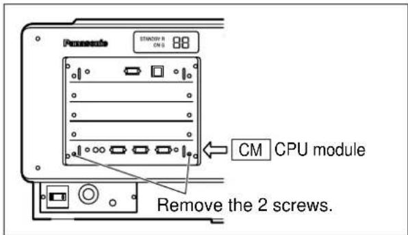
④ Remove the connector that connects CM5 to CM6, then use the same connector to connect CM6 to CM7.
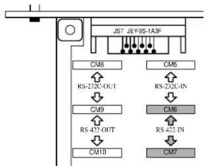
flowchart
graph TD
    A["JST JEY-9S-1A3F"] --> B["CM8"]
    A --> C["CM6"]
    B --> D["RS-232C-OUT"]
    C --> E["RS-232C-IN"]
    D --> F["CM9"]
    E --> G["CM6"]
    F --> H["RS-422-OUT"]
    G --> I["RS-422-IN"]
    H --> J["CM10"]
    I --> K["CM7"]
⑤ Refit the GRU module.
⑥ Plug the projector into the wall outlet and set the front MAIN POWER switch to ON.
⑦ Check that the LED to the left of the RS-232C-IN port is lit red.
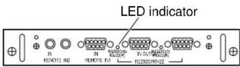
● Restoring the original RS-232C-IN port function
① If the projector power is ON, turn it OFF by pressing the remote-control (or on the projector) POWER key, and wait for approximately 5 minutes until the cooling fan stops.
② Set the front MAIN POWER switch of the projector to OFF, then unplug the projector from the supply outlet.
③ Remove the CPM module.
④ Remove the connector that connects CM6 to CM7, then use the same connector to connect CM5 to CM6.
⑤ Refit the CPM module.
⑥ Plug the projector into the wall outlet and set the front MAIN POWER switch to ON.
⑦Check that the LED to the left of the RS-232C-IN port is lit green.

Selecting the RS-422 Serial Interface (continued)
■ Converting the RS-232C-OUT port into an RS-422-OUT port
①If the projector power is ON, turn it OFF by pressing the remote-control (or on the projector) POWER key, and wait for approximately 5 minutes until the cooling fan stops.
② Set the front MAIN POWER switch of the projector to OFF, then unplug the projector from the supply outlet.
③ Remove the OENU module.
See “■onverting the RS-232C-IN port into an RS-422-IN port”.
④ Remove the connector that connects CM8 to CM9, then use the same connector to connect CM9 to CM10.

flowchart
graph TD
    A["JST JEY-9S-1A3F"] --> B["CM8"]
    A --> C["CM5"]
    B --> D["RS-232C-OUT"]
    C --> E["RS-232C-IN"]
    D --> F["CM9"]
    E --> G["CM6"]
    F --> H["RS-422-OUT"]
    G --> I["RS-422-IN"]
    H --> J["CM10"]
    I --> K["CM7"]
⑤ Refit the GRU module.
⑥ Plug the projector into the wall outlet and set the front MAIN POWER switch to ON.
⑦ Check that the LED to the left of the RS-232C-OUT port is lit red.

● Restoring the original RS-232C-OUT port function
① If the projector power is ON, turn it OFF by pressing the remote-control (or on the projector) POWER key, and wait for approximately 5 minutes until the cooling fan stops.
② Set the front MAIN POWER switch of the projector to OFF, then unplug the projector from the supply outlet.
③ Remove the CEM module.
④ Remove the connector that connects CM9 to CM10, then use the same connector to connect CM8 to CM9.
⑤ Refit the CPM module.
⑥ Plug the projector into the wall outlet and set the front MAIN POWER switch to ON.
⑦ Check that the LED to the left of the RS-232C-OUT port is lit green.

RS-422 port pin functions
| RS-422-IN | ||
| Pin no. | Pin function | Description |
| 1 | NC | No connection |
| 2 | TXD(-) | Transmit data terminal (-) |
| 3 | RXD(+) | Receive data terminal (+) |
| 4 | - | Internally connected to pin 6. |
| 5 | NC | No connection |
| 6 | - | Internally connected to pin 4. |
| 7 | TXD(+) | Transmit data terminal (+) |
| 8 | RXD(-) | Receive data terminal (-) |
| 9 | FG | Ground |
| RS-422-OUT | ||
| Pin no. | Pin function | Description |
| 1 | NC | No connection |
| 2 | RXD(-) | Receive data terminal (-) |
| 3 | TXD(+) | Transmit data terminal (+) |
| 4 | - | Internally connected to pin 6. |
| 5 | NC | No connection |
| 6 | - | Internally connected to pin 4. |
| 7 | RXD (+) | Receive data terminal (+) |
| 8 | TXD (-) | Transmit data terminal (-) |
| 9 | FG | Ground |
Using the network module
The network module for this unit has a LAN interface, so the unit can be controlled from the web browser of a PC. The network module has an automatic send function for e-mail. Mail can be sent to a previously set e-mail address when a problem occurs, or when the set value for the lamp usage time is attained.
Connection example
A LAN cable is necessary when using the network module.

flowchart
graph TD
    PC["PC"] -->|LAN cable (straight)| Hub["Hub"]
    PC -->|LAN cable (straight)| Projector["Projector"]
    Hub -->|LAN cable (straight)| Projector
    PC -->|LAN cable (straight)| Projector
- A web browser is necessary when using this function. Check beforehand that a web browser is available.
- Compatible with a PC running Microsoft Windows 95/98/Me or WindowsNT4.0 / Windows2000.
- Suitable web browsers are Internet Explorer 5.01 or higher, or Netscape Navigator/Communicator 4.75 or higher.
- When using the e-mail function, it is necessary to communicate with the e-mail server. Check that e-mail can be used beforehand.
• LAN cable should be a straight type that is category 5 compatible.
• LAN cable length to be less than 100 m.
Network module parts identification and function

NOTE
- If you touch the LAN terminal with a hand (body) charged with static electricity, it may cause malfunction due to discharge of static electricity. Be careful not to touch the LAN terminal or metal parts of the LAN cable.
Initial setting of network module
Operating procedure

①Press the MENU button. ... The MENU screen will be displayed.
②Press the UP (▲and DOWN ( ) arrow buttons to select OPTION.

③Press the ENTER button. ... The OPTION screen will be displayed.
④Press the UP (▲and DOWN ( ) ▼row buttons to select NETWORK MODULE SETTING.

⑤Press the ENTER button. ... NETWORK MODULE SETTING screen will be displayed.
⑥ Press the UP (▲ and DOWN ( ) ▶row buttons to select each item and press the ENTER button to change the setting.(refer to next page)
⑦ Press the UP (▲ and DOWN ( ) ▼row buttons to select STORE and press the ENTER button twice.
- After the online lamp of the network module goes out, it lights up again.
NOTE
- It takes about 2 minutes for settings to take effect.
- Do not turn off the main power supply until the online lamp of the network module lights up again.
| Item | Function | Description |
| HOSTNAME | Host name display and setting | Change if necessary when using a DHCP server etc. |
| DHCP | DHCP client function | Turn the DHCP item ON when automatically obtaining IP addresses using a DHCP server. Turn it OFF when not using a DHCP server. |
| IP ADDR | IP address display and setting | Input an IP address when not using a DHCP server. |
| NET MASK | Net mask display and setting | Input the net mask when not using a DHCP server. |
| GATEWAY | Gateway address display and setting | Input a gateway address when not using a DHCP server. |
| MAC ADDR | MAC address display | This displays the unique media access control (MAC) address of the network equipment. This may be necessary when using a DHCP server. |
- When using a DHCP server, check that the DHCP server starts up.
•Inquire with the network administrator about the IP address, net mask and gateway.
Accessing from a web browser
① Start up the PC's web browser.

②Input the IP address set on the unit in the URL input field of the web browser.
③Input user1 in the user name field, and input panasonic (lower case letters) in the password field.
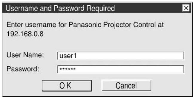
④ When OK is pressed, the top page is displayed.

NOTE
- Please avoid starting up multiple web browsers simultaneously, and performing setting and control.
- This works when the online lamp of the network module is lit.
- First, change the password.
Top page

Initial setting page

Network setting page

Projector control page

Status display page
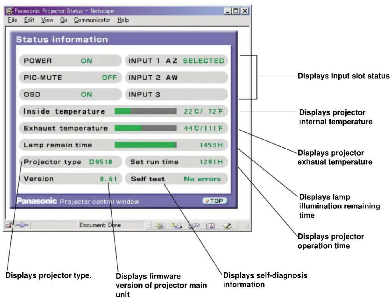
E-mail setting page
- This enables automatic sending of mail to up to two mail addresses.

Input the e-mail address to send mail to.
Select conditions for sending e-mail.
Error: When an error occurs in self-diagnosis
Warning LAMP1: When the lamp illumination remaining time reaches the time set in the column on the right side.
Warning LAMP2: When the lamp illumination remaining time reaches the time set in the column on the right side.
Warning Inside Temperature: When the internal temperature reaches the value set in the column above.
Warning Exhaust Air Temperature: When the exhaust temperature reaches the value set in the column above.
E-mail setting page (continue)
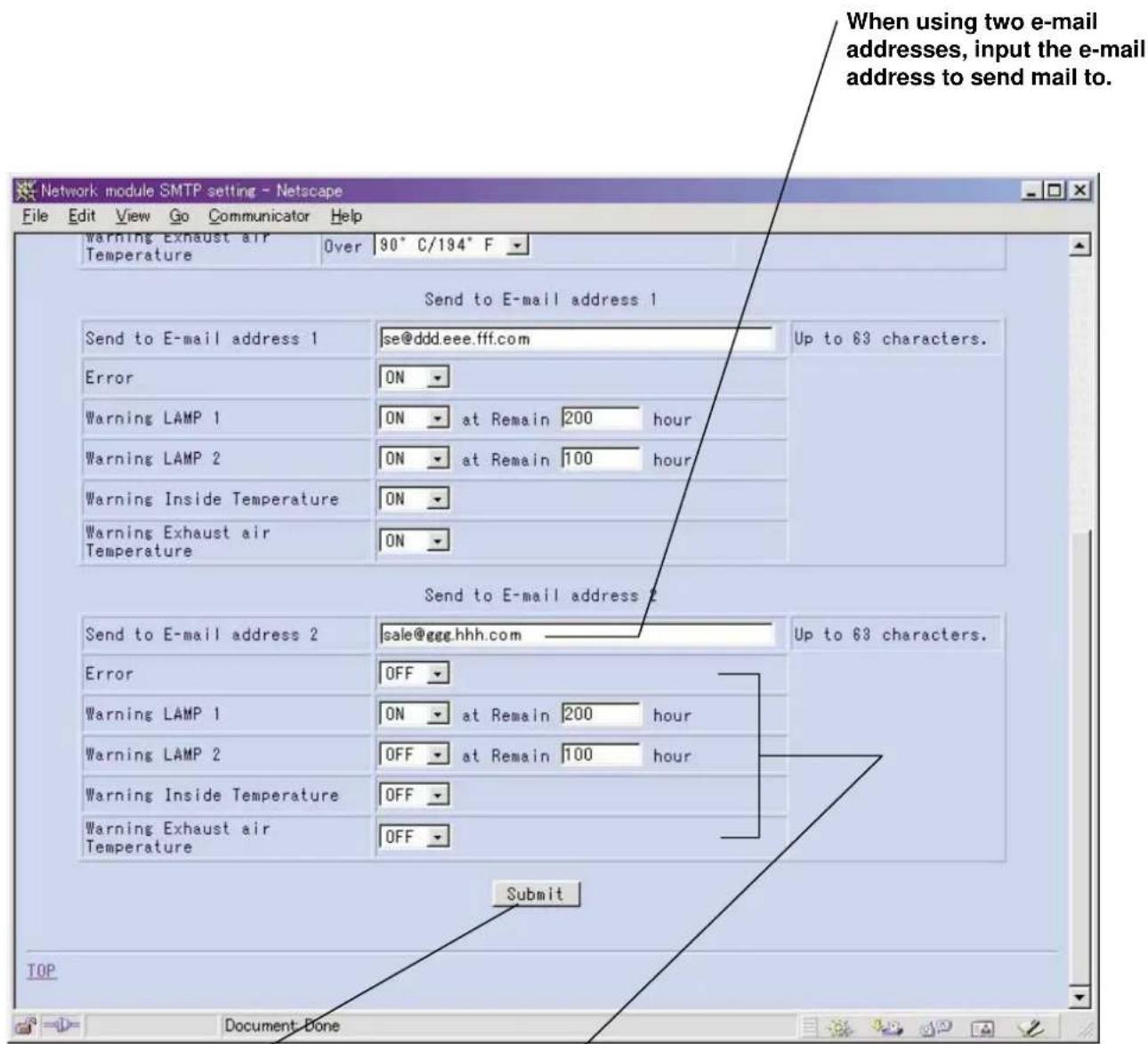
After all input is finished, press the Submit button.
Select the conditions for sending e-mail
Error: When an error occurs in self-diagnosis
Warning LAMP1: When the lamp illumination remaining time reaches the time set in the column on the right side.
Warning LAMP2: When the lamp illumination remaining time reaches the time set in the column on the right side.
Warning Inside Temperature: When the internal temperature reaches the value set in the column above.
Warning Exhaust Air Temperature: When the exhaust temperature reaches the value set in the column above.
Firmware update page
(Firmware updating should only be done by a person with specialized knowledge.)


- When rewriting is finished, this message is displayed.
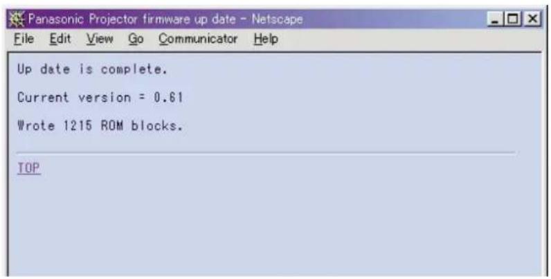
Returning the network module settings to the factory shipment condition
The following procedure allows the user to reset all of the network module settings (such as the IP address, password and e-mail settings) to the factory shipment condition.
Procedure
①Using the "POWER" button on the remote control, set the unit power supply to the standby state.
②Using an object with a pointed tip, press and hold the FUNCTION switch for 3 seconds. The ON-LINE lamp will flash, and then go out about 30 seconds later.
③Turn off the MAIN POWER.
④ Using an object with a pointed tip, press and hold the FUNCTION switch and turn on the MAIN POWER. When the ON-LINE lamp begins flashing quickly, release the FUNCTION switch.
⑤When the ON-LINE lamp lights up, the procedure is complete.
NOTE
- Do not operate the FUNCTION switch with an object such as a pencil whose tip can break easily.
Cleaning the air filter
- If too much dust accumulates on the air filter, the temperature inside the projector will rise and may cause the power to turn off. Clean the air filter approximately every 500 hours of use (varies with the environment in which the projector is used).

CAUTION

Consult a service technician to clean or replace the air filter.
Replacing the lamp unit

DANGER

Some dangers are associated with the replacing of the lamp. If lamp replacement becomes necessary, have the lamp unit replaced by a qualified service person, experienced in working with Xenon lamps.
Notes on handling the lamp unit
- The lamp unit is sold separately and consult a Panasonic authorized dealer or service center.
Part No.: ET-LAD9610
Lamp unit replacement period
The life span of this lamp unit is 1 500 hours maximum, after which it will need replacing (recommended replacement time is 1 000 hours). in the normal usage mode. The operating life of the lamp also depends on the number of times it is turned on and off. Turning on and off the lamp at frequent intervals will decrease its operating life.
The projector has an automatic shut-off function that automatically stops the light emission of the lamp once its total usage time exceeds 1 500 hours to prevent any accidents caused by the end of its life. And the on-screen displays below appear according to its usage time.
- Warning display between 200 and 50 hours of lamp remain time The lamp remain time will be displayed in yellow at the bottom-left of the screen.
(This display will disappear if any of the buttons on the remote control unit or projector are pressed.)
- Warning display between 50 and 0 hours of lamp remain time The lamp remain time will be displayed in red at the bottom-left of the screen for one minute. After this, it will repeatedly turn off for 30 minutes and then be displayed again for one minute. (This repeating display will be cancelled if any of the buttons on the remote control unit or projector are pressed.)
- Warning display after 0 hour of lamp remain time A warning message to urge the replacement of the lamp will be displayed in red at the bottom left of the screen for 10 minutes. After that, the automatic shut-off function will set the projector to the standby mode.
WARNING! LAMP REMAIN : 200h
WARNING! LAMP REMAIN : 50 h
WARNING! REPLACE THE LAMP
NOTE
- The lamp used as the light source has a maximum life span of 1,500 hours. However, the amount of time the lamp is turned on and the intervals between turning on, the environment in which the projector is used, and the individual characteristics of each lamp will affect this time. The light may flicker or fail to turn on before 1,500 hours has elapsed, so it is therefore recommended that a spare be made available.
- The lamp service life remaining time is the time the equipment has been used in LAMP POWER: NORMAL and CONTRAST MODE: NORMAL or HIGH.
Before asking for service, check the following points.
| Symptom Check the following Symptom Check the following | |||
| Power does not turn on. | Is the power turned on at the power point?Is the power cord disconnected from the power point?Is the MAIN POWER switch turned to OFF?Is the REMOTE IN 1 connector being used for external control?Is the ID number setting correct? | On-screen displays do not appear. | Has the ON SCREEN button been pressed to turn off the displays? |
| The remote control unit does not work. | Have the batteries been inserted with the correct polarity?Is something obstructing the path between the remote control unit and the remote control signal receptor of the projector?Is the remote control being used outside the effective range?Is the REMOTE IN 1 connector being used for external control?Is a remote control cable being connected to the REMOTE IN 2 connector ? (in the wireless mode) | ||
| No picture appears. | Is the picture transmission cable disconnected?Is the signal source connected to the projector operating normally?Has the picture mute function been turned on?Does the video signal format match the input signal format?Is Y/C signal selected for composite input, or vice versa? | ||
| Color is misaligned when special signals are input. | Has the input source been changed to a new type of signal which is not registered?Does the video signal format match the input signal format? | LAN connection to the unit is impossible | Is the LAN cable connected correctly?Are the unit's IP address, net mask and gateway address settings compatible with the connected network?Is the web browser URL or IP address designation correct? |
| The contrast and brightness of the picture cannot be adjusted | Is the REMOTE IN 1 connector being used for external control? | ||
| Connection was denied during LAN connection to the unit | Are the user name and password correct? | ||

- Explanation about the DMD™ devices
The DMD ^™ devices are produced using high-precision technology (Three sheets of approximately 780,000 pixels (for PT-D9510E)/1,310,000 pixels (for PT-D9610E) are used for the projector.), but there might be extremely small chipped or brighter points of the picture on the screen.
Specifications
| Power Supply | 200 V – 240 V AC (single-phase, 3-wire), 14 A (Max.) |
| Power Consumption | 2.2 kW |
| Approx. 13 W during standby (when cooling fan is stopped) | |
| Operating environment temperature | 0 °C – 40 °C : NORMAL lamp power0 °C – 35 °C : HIGH lamp powerIf the power is turned on when the temperature is around 0 °C, a warming-up time of about five minutes will be required before a picture can be projected. |
| Storage environment | Temperature: -25 °C – 65 °C Humidity: 10 % – 80 % (with no condensation) |
| DMDTMelements | Element size: 0.9 inches (aspect ratio ; 4:3) : PT-D9510E: 1.1 inches (aspect ratio ; 5:4) : PT-D9610EDisplay method: 3 DMDTMelements, DLPTMsystemPixels: 1 024 dots × 768 lines, (3 sheets) : PT-D9510E: 1 280 dots × 1 024 lines, (3 sheets) : PT-D9610E |
| Lamp | 1 600 W Xenon lamp (recommended replacement period 1 000 hours) |
| Luminosity | 9 000 lm (ANSI) : LAMP POWER NORMALPT-D9510E10 000 lm (ANSI) : LAMP POWER HIGH10 000 lm (ANSI) : LAMP POWER NORMALPT-D9610E12 000 lm (ANSI) : LAMP POWER HIGH |
| Projection method | Ceiling or Floor/Front or Rear (menu selectable) |
| Keystone compensation | Max. elevation angle : ±10 ° or less |
| Optical axis shift volume | Top and bottom : 10/0 – 0/10 Left and right : 8/2 – 2/8(electromotion) |
| Projection screen size | Between 100"(2.5 m) and 600"(15 m) when separate zoom lens is fitted Between 100"(2.5 m) and 180"(4.5 m) when separate fixed focus lens is fitted)PT-D9510EBetween 100"(2.5 m) and 600"(15 m) when separate zoom lens is fitted Between 100"(2.5 m) and 200"(5.0 m) when separate fixed focus lens is fitted)PT-D9610E |
| Screen aspect ratio | 4:3 when separate zoom lens or fixed focus lens is fitted (PT-D9510E)5:4 when separate zoom lens or fixed focus lens is fitted (PT-D9610E) |
| Input signals | With ET-MD95RGB analogue RGB input module (sold separately) installedBNC termination × 5Video signal input block Impedance : 75 ΩSync signal input block Impedance : 75 Ω / 1 kΩR/PR/Cr 0.7 V [p-p] , 1.0 V [p-p] with BETACAM inputG/Y 0.7 V [p-p] (1.0 V [p-p] when SYNC ON G/Y signal is input)B/PB/Cb 0.7 V [p-p] , 1.0 V [p-p] with BETACAM inputComposite sync 0.6 V [p-p] – 4.0 V [p-p] with 75 ΩTTL level with 1 kΩSeparate sync 0.6 V [p-p] – 4.0 V [p-p] with 75 ΩTTL level with 1 kΩAnalogue RGB input signalfH: 15 kHz–100 kHz, fv: 24 Hz–120 Hz, dot clock frequency: 20 MHz–162 MHzColour difference input signalApplicable formats: 480i, 576i, 480p, 720/60p, 1080/60i(1035/60i)1080/50i, 1080/30p, 1080/25p, 1080/24p, 1080/24sF |
| With ET-MD95VM2 video signal (NTSC, NTSC4.43, PAL, SECAM,PAL-M, PAL60, PAL-N) input module (sold separately) installedVideo signal 1.0 V [p-p] Impedance: 75 Ω BNC terminationY signal 1.0 V [p-p] Impedance: 75 Ω BNC terminationC signal 0.286 V [p-p] Impedance: 75 Ω BNC terminationCb signal 0.7 V [p-p] Impedance: 75 ΩBNC terminationCr signal 0.7 V [p-p] Impedance: 75 ΩBNC termination | |
| Input signals | With serial digital input module (sold separately) installedET-MD95SD1 (for 480i/576i)SERIAL IN (SMPTE259M) BNC terminationSERIAL OUT (SMPTE259M) BNC terminationET-MD95SD2 (for 480p/480i/576i)SERIAL MAIN IN/SUB IN (SMPTE259M/294M) BNC terminationSERIAL MAIN OUT/SUB OUT (SMPTE259M/294M) BNC terminationET-MD95SD3 (for HD SDI)HD-SERIAL IN (SMPTE292M) BNC terminationHD-SERIAL OUT (SMPTE292M) BNC termination |
| With ET-MD95T TMDS input module (sold separately) installedMDR26 connectorApplicable signals SVGA, XGA, SXGA | |
| Contrast ratio | 1000:1 (100% black-and-white pattern) when the contrast mode is super. |
| Connection terminals | 3 input module connection slotsRS-232C/RS-422 input/output connectors D-SUB 9-pin × 2 for computer controlREMOTE IN 1 connector D-SUB 9-pin for external controlREMOTE 2 IN/OUT terminals M3 pin jack × 2 For wired remote control unit and serial controlLAN terminal RJ-45 jack, for network connection |
| Power cord length | 2.5 m (8.2') |
| Cabinet | Aluminium, Plastic (denatured) |
| Weight | 100 kg (220 lb) (not including separate projection lens) |
| Dimensions | 75.3 cm/29.6" (W) × 42.8 cm/16.9" (H) [including legs] × 105.1 cm/41.4" (D) |
| (Remote control unit)Number of functionsPower supplyOperating range | 34 (including lighting function)3 V DC (AA batteries × 4)Within approx. 12 m / 39.3' directly in front of receptor (when operated as wireless unit)Within 15 m / 49.2' (when operated as wired unit) |
| WeightDimensions | Approx. 350 g / 0.77 lb (including batteries)14.0 cm / 5.5" (W) × 3.6 cm / 1.4" (H) × 18.1 cm / 7.1" (L) |
Accessories
- Remote control unit 1
- AA-size batteries 4
- Remote control cable (15 m / 49.2')...... 1
- Remote control unit strap 1
Sold separately
Select from the range available in accordance with the setting-up location and system requirements.
| NAME | MODEL NO. | Applicable model | |
| Projection lenses | Zoom lens 1.5 – 2.5 : 1 | ET - D95LE1 | Dedicated to the PT-D9510E |
| Zoom lens 2.5 – 4.0 : 1 | ET - D95LE2 | ||
| Zoom lens 4.0 – 7.0 : 1 | ET - D95LE3 | ||
| Zoom lens 1.5 – 2.0 : 1 | ET - D95LE5 | Dedicated to the PT-D9610E | |
| Zoom lens 2.0 – 2.5 : 1 | ET - D95LE6 | ||
| Zoom lens 2.5 – 4.0 : 1 | ET - D95LE7 | ||
| Zoom lens 4.0 – 7.0 : 1 | ET - D95LE8 | ||
| Fixed focal lens 0.8 : 1 | ET - D95LE9 *1 | Shared with the PT-D9510E and PT-D9610E | |
| Modules | RGB input module (RGB/YPbPr/YCbCr) | ET - MD95RGB | |
| Video signal input module (NTSC, PAL, SECAM, NTSC4.43, PAL-M, PAL60, PAL-N) | ET - MD95VM2 | ||
| Serial digital input module (480i/576i) | ET - MD95SD1 | ||
| Serial digital input module (480p/480i/576i) | ET - MD95SD2 | ||
| HD-Serial digital input module | ET - MD95SD3 | ||
| Other | TMDS input module | ET - MD95T | |
| Replacement lamp unit | ET - LAD9610 | ||
| Ceiling mount bracket | ET - PKD95 | ||
| Dual stacking mount bracket | ET - DFD95 | ||
| Visor | ET - MSPD8500 | ||
NOTE
* 1 Refer to the ET-D95LE9 operating instructions when installing.
Dimensions
UNIT : mm (inch)
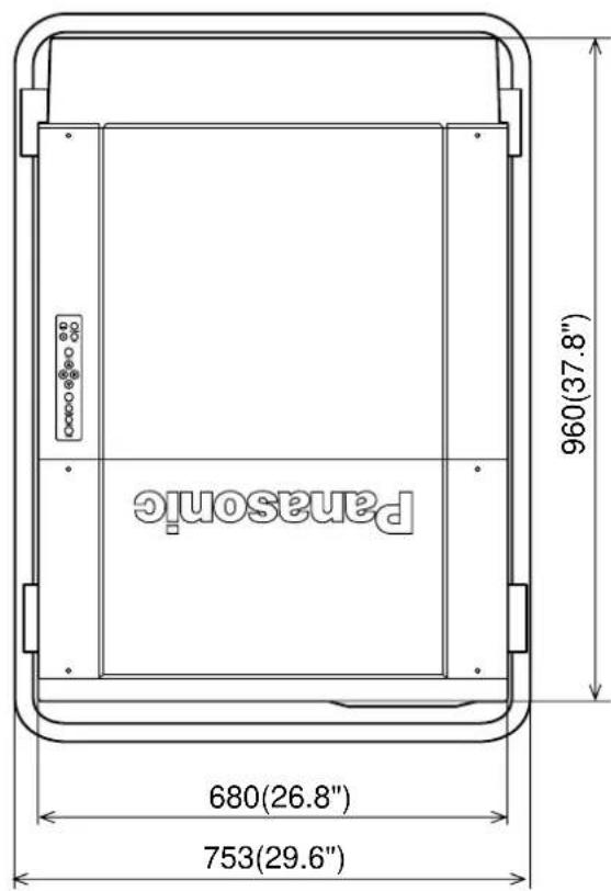


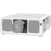
- DLP™ based Projector Commercial Use
- Operating Instructions
- Dear Panasonic Customer:
- Contents
- Product Outline
- Features
- Contrast of 1000:1 realized
- Network functions are standard equipment
- High-density, high-quality computer images can also be projected
- A new processing circuit for moving images provides excellent moving image quality
- Projects a wide range of image sizes from 2,5 m (100 inches) to 15 m (600 inches)
- A variety of different input sources can be used
- Compatible with high-resolution systems used for multi-screen projection.
- Other useful functions also included
- Note:
- Trademark Acknowledgements
- IMPORTANT SAFETY NOTICE
- Precautions with regards to safety
- WARNING
- Setting-up
- Installation should only be carried out by a qualified technician.
- At least three people are needed to set up the projector.
- Check the strength of the installation location.
- Avoid installing the projector in any of the following places:
- Do not connect any power supply to the projector other than one with power supply voltage indicated (single-phase, 3-wire, 200 V–240 VAC)
- A special ceiling mount bracket (sold separately) is required for ceiling installation.
- Use commercially-available screens.
- Keep external light away from the screen.
- Allow enough space around the projector for maintenance to be carried out.
- Always connect to a secure earth.
- When using the projector
- If a problem occurs during use
- Caution!
- Precautions on handling
- CAUTION
- A dedicated power supply must be used.
- Avoid setting up in places which are subject to vibration or shocks.
- Do not place the projector near high-voltage power lines or motors.
- The projection distance will vary depending on the projection lens (sold separately) which is used.
- If installing the projector to the ceiling, be sure to have a qualified technician carry out the work.
- Do not move the projector after it has been installed and adjusted.
- Notes on use
- In order to get the best picture quality
- Do not touch the surface of the projection lens with your bare hands.
- About the screen
- Cleaning and maintenance
- Wipe the cabinet with a soft, dry cloth.
- Do not wipe the lenses with a cloth that is dusty or which produces lint.
- Name and function of each part
- POWER button
- SYSTEM SELECTOR button
- Arrow buttons
- LENS button
- PIC-MUTE button
- Network terminals
- Handle
- MAIN POWER switch
- REMOTE IN 2 input/output connector
- INPUT button
- MENU button
- ENTER button
- Control level buttons
- Power indicator
- Installation bays for input modules (sold separately)
- RS-232C/RS-422 OUT connector
- RS-232C/RS-422 IN connector
- REMOTE IN 1 connector
- Name and function of each remote control part
- STD (standard) button
- Input select buttons
- CONTRAST button
- BRIGHT buttons
- Numeric buttons
- ON SCREEN button
- NEXT button
- ID SELECT button
- ID ALL button
- Name and function of each remote control part (continued)
- If the button illumination is flashing
- LIGHT button
- Battery compartment cover
- Before using the remote control unit
- Inserting the batteries
- Note on using the batteries
- Notes when using the remote control unit
- Attaching the strap
- Operating range of remote control unit
- NOTE
- Using the remote control unit with the cable
- Turning the power ON and OFF
- On-screen menu operation guide
- Before using the projector
- Installing the projection lens
- Setting procedure
- Setting up the projector
- Installing to the floor (Including the direct rear-mounting)
- Installing to the ceiling (Including direct rear-projection)
- Installing drawing of the screen and the projector (unit : mm (inches))
- Position of the ceiling mount bracket on the ceiling
- - Locating the positions to mount the suspension bolts on the ceiling surface
- Projection distance for each projection lens
- (sold separately)
- Calculation of the projection distance for each projection lens (for PT-D9510E)
- Calculation of the projection distance for each projection lens (for PT-D9610E)
- Adjusting projector feet
- Setting the projection method
- Adjusting the lens
- Adjusting the focus
- Adjustment procedure
- Adjusting the lens position (optical shift)
- Adjustment range after lens position (optical shift)
- Installing the input module
- - Types of input module (sold separately)
- - Input slot numbers
- Installing the input modules
- Installation procedure
- Connecting the input module signal source
- Connecting the signal source to the input module for analogue RGB signals
- Connecting an analogue RGB signal source
- CAUTION:
- Connecting a component signal source
- Analogue RGB signals that can be input
- Connecting a video signal source
- Connecting the signal source to the input module for video signals
- Connecting the signal source to the input module for TMDS signals
- Connecting the signal source to the input module for serial digital signals
- Selecting the input signal
- Selecting the system format
- Selecting the signal of ET-MD95VM2(sold separately)
- Registering input signal data
- Registration new signal
- Registration procedure
- When the memory does not allow new signal registration because it is full
- Overwriting registration procedure
- Sub-memory
- Sub-memory storage
- Sub-memory switching
- Sub-memory delete
- On-screen display
- Restrictions
- Sub-memory list
- Using the RGB REALITY mode
- Adjusting the picture automatically
- General automatic adjustment
- Special signal automatic adjustment
- Adjusting the picture manually
- Adjusting the input signal resolution
- Adjusting the clock phase
- Adjusting the picture position
- < When adjusting the horizontal position
- < When adjusting the vertical position
- Adjusting the blanking
- < When adjusting the upper blanking
- < When adjusting the lower blanking
- < When adjusting the left blanking
- < When adjusting the right blanking
- Adjusting the clamp position
- Picture mute function
- Adjusting the keystone(Trapezoidal distortion)
- Adjusting the picture to the desired setting
- Adjustment procedure ... Adjusting the COLOUR setting
- Adjusting the white balance
- Adjustment procedure (Project a signal to be adjusted)
- Adjusting the picture quality
- Adjusting the picture size
- Size modes
- Screen examples for different size settings (For PT-D9510E)
- Screen examples for different size settings(For PT-D9610E)
- Power up function
- Contrast switching function
- Switching procedure
- When inputting BETACAM with YCbCr 480i
- Method of switching input impedance(signal level) for sync input
- Displaying a test pattern
- Operating procedure
- Displaying the projector settings
- Display procedure
- Adjusting the edge blending
- Adjustment marker
- Adjusting the color matching
- For adjusting
- Setting and specifying ID numbers
- Setting ID numbers
- Setting remote control unit ID numbers
- Setting method
- If you do not know the ID number assigned to the projector
- Using the RS-232C connectors
- Commands
- RS-232C settings
- Selecting the RS-422 Serial Interface
- ■ Converting the RS-232C-IN port into an RS-422-IN port
- ● Restoring the original RS-232C-IN port function
- Selecting the RS-422 Serial Interface (continued)
- ■ Converting the RS-232C-OUT port into an RS-422-OUT port
- ● Restoring the original RS-232C-OUT port function
- Using the network module
- Connection example
- Network module parts identification and function
- Initial setting of network module
- Accessing from a web browser
- Top page
- Initial setting page
- Network setting page
- Projector control page
- E-mail setting page
- E-mail setting page (continue)
- Firmware update page
- Returning the network module settings to the factory shipment condition
- Procedure
- Cleaning the air filter
- Replacing the lamp unit
- DANGER
- Notes on handling the lamp unit
- Lamp unit replacement period
- Before asking for service, check the following points.
- Specifications
- Accessories
- Sold separately
- Dimensions
Brand : PANASONIC
Model : PT-D9510
Category : Video projector