
DJM-850-W - Mixer PIONEER - Free user manual and instructions
Find the device manual for free DJM-850-W PIONEER in PDF.
| Product type | 4-channel DJ mixer |
| Brand | PIONEER |
| Model | DJM-850-W |
| Dimensions (W x H x D) | 320 mm x 108 mm x 381 mm |
| Weight | 7.7 kg |
| Power supply | AC 220 V – 240 V, 50/60 Hz, power consumption 32 W (standby 0.45 W) |
| USB sound card | 4 outputs / 4 stereo inputs, 24-bit / 96 kHz, ASIO/Core Audio compatible |
| Built-in effects | BEAT COLOR FX, SOUND COLOR FX (NOISE, GATE, CRUSH, FILTER), BEAT EFFECT (13 types) |
| Per-channel equalizer | 3-band (HI, MID, LOW) with EQ or ISOLATOR mode |
| Crossfader and faders | Crossfader with adjustable curve, high-performance channel faders with P-LOCK caps |
| Input connections | 4x RCA (CD/LINE), 2x RCA (LINE), 2x RCA (PHONO), 2x XLR/jack (MIC1 and MIC2), 1x RCA (RETURN) |
| Output connections | 1x XLR (MASTER1), 1x RCA (MASTER2), 1x RCA (REC OUT), 1x 6.35 mm jack (BOOTH), 1x 6.35 mm jack (SEND), 1x RCA coaxial (DIGITAL MASTER OUT), 1x stereo jack (PHONES) |
| MIDI connectivity | USB MIDI, MIDI OUT 5-pin DIN connector |
| Talkover function | Normal or Advanced mode, adjustable attenuation from -6 dB to -24 dB |
| Fader start | Compatible with Pioneer DJ players via CONTROL ports (4 x 3.5 mm mini-jack) |
| Operating temperature | +5 °C to +35 °C, humidity < 85 % (no condensation) |
| Maintenance and cleaning | Clean the connectors and plugs with a dry cloth. Disconnect the power supply before any cleaning. |
| Safety | Do not open the unit, do not expose to water or open flames, ensure adequate ventilation (5 cm at rear, 3 cm on sides). |
| Spare parts and repairability | No user-serviceable parts. Contact Pioneer customer service or an authorized dealer. |
| General information | Warranty included. Domestic use. Keep the manual. |
Frequently Asked Questions - DJM-850-W PIONEER
User questions about DJM-850-W PIONEER
0 question about this device. Answer the ones you know or ask your own.
Ask a new question about this device
Download the instructions for your Mixer in PDF format for free! Find your manual DJM-850-W - PIONEER and take your electronic device back in hand. On this page are published all the documents necessary for the use of your device. DJM-850-W by PIONEER.
USER MANUAL DJM-850-W PIONEER
DJM-850-K DJM-850-S DJM-850-W
DJ MIXER TABLE DE MIXAGE DJ-MISCHPULT
The Pioneer website shown above offers FAQs, information on software and various other types of information and services to allow you to use your product in greater comfort.
Operating Instructions
Mode d'emploi
Bedienungsanleitung
Thank you for buying this Pioneer product. Please read through these operating instructions so you will know how to operate your model properly. After you have finished reading the instructions, put them away in a safe place for future reference. In some countries or regions, the shape of the power plug and power outlet may sometimes differ from that shown in the explanatory drawings. However the method of connecting and operating the unit is the same.
IMPORTANT

The lightning flash with arrowhead symbol, within an equilateral triangle, is intended to alert the user to the presence of uninsulated “dangerous voltage” within the product’s enclosure that may be of sufficient magnitude to constitute a risk of electric shock to persons.
CAUTION
RISK OF ELECTRIC SHOCK DO NOT OPEN
CAUTION:
TO PREVENT THE RISK OF ELECTRIC SHOCK, DO NOT REMOVE COVER (OR BACK). NO USER-SERVICEABLE PARTS INSIDE. REFER SERVICING TO QUALIFIED SERVICE PERSONNEL.

The exclamation point within an equilateral triangle is intended to alert the user to the presence of important operating and maintenance (servicing) instructions in the literature accompanying the appliance.
D3-4-2-1-1_A1_En

If you want to dispose this product, do not mix it with general household waste. There is a separate collection system for used electronic products in accordance with legislation that requires proper treatment, recovery and recycling.
Private households in the member states of the EU, in Switzerland and Norway may return their used electronic products free of charge to designated collection facilities or to a retailer (if you purchase a similar new one).
For countries not mentioned above, please contact your local authorities for the correct method of disposal.
By doing so you will ensure that your disposed product undergoes the necessary treatment, recovery and recycling and thus prevent potential negative effects on the environment and human health.
K058b_A1_En
WARNING
This equipment is not waterproof. To prevent a fire or shock hazard, do not place any container filled with liquid near this equipment (such as a vase or flower pot) or expose it to dripping, splashing, rain or moisture.
D3-4-2-1-3_A1_En
WARNING
Before plugging in for the first time, read the following section carefully.
The voltage of the available power supply differs according to country or region. Be sure that the power supply voltage of the area where this unit will be used meets the required voltage (e.g., 230 V or 120 V) written on the side panel.
D3-4-2-1-4*_A1_En
WARNING
To prevent a fire hazard, do not place any naked flame sources (such as a lighted candle) on the equipment.
D3-4-2-1-7a_A1_En
Operating Environment
Operating environment temperature and humidity: +5 °C to +35 °C (+41 °F to +95 °F); less than 85 %RH (cooling vents not blocked)
Do not install this unit in a poorly ventilated area, or in locations exposed to high humidity or direct sunlight (or strong artificial light)
D3-4-2-1-7c*_A1_En
Before making or changing the connections, switch off the power and disconnect the power cord from the AC outlet.
D44-9-3_A1_En
This product is for general household purposes. Any failure due to use for other than household purposes (such as long-term use for business purposes in a restaurant or use in a car or ship) and which requires repair will be charged for even during the warranty period.
K041_A1_En
POWER-CORD CAUTION
Handle the power cord by the plug. Do not pull out the plug by tugging the cord and never touch the power cord when your hands are wet as this could cause a short circuit or electric shock. Do not place the unit, a piece of furniture, etc., on the power cord, or pinch the cord. Never make a knot in the cord or tie it with other cords. The power cords should be routed such that they are not likely to be stepped on. A damaged power cord can cause a fire or give you an electrical shock. Check the power cord once in a while. When you find it damaged, ask your nearest PIONEER authorized service center or your dealer for a replacement.
S002*_A1_En
VENTILATION CAUTION
When installing this unit, make sure to leave space around the unit for ventilation to improve heat radiation (at least 5 cm at rear, and 3 cm at each side).
WARNING
Slots and openings in the cabinet are provided for ventilation to ensure reliable operation of the product, and to protect it from overheating. To prevent fire hazard, the openings should never be blocked or covered with items (such as newspapers, table-cloths, curtains) or by operating the equipment on thick carpet or a bed.
D3-4-2-1-7b*_A1_En
If the AC plug of this unit does not match the AC outlet you want to use, the plug must be removed and appropriate one fitted. Replacement and mounting of an AC plug on the power supply cord of this unit should be performed only by qualified service personnel. If connected to an AC outlet, the cut-off plug can cause severe electrical shock. Make sure it is properly disposed of after removal. The equipment should be disconnected by removing the mains plug from the wall socket when left unused for a long period of time (for example, when on vacation).
D3-4-2-2-1a_A1_En
CAUTION
The POWER switch on this unit will not completely shut off all power from the AC outlet. Since the power cord serves as the main disconnect device for the unit, you will need to unplug it from the AC outlet to shut down all power. Therefore, make sure the unit has been installed so that the power cord can be easily unplugged from the AC outlet in case of an accident. To avoid fire hazard, the power cord should also be unplugged from the AC outlet when left unused for a long period of time (for example, when on vacation).
D3-4-2-2-2a*_A1_En
Contents
How to read this manual
The names of displays, menus, and buttons in this manual are enclosed in brackets. (e.g. [MASTER] channel, [ON/OFF], [File] menu)
01 Before start
Features 5
What's in the box....5
02 Connections
Rear panel 6
Connecting input terminals....7
Connecting output terminals 7
Connecting to the control panel....8
About the driver software and setting utility software....8
03 Operation
Basic Operation 14
Advanced Operations....16
04 Types of effects
BEAT COLOR FX/SOUND COLOR FX effect types.... 18
Types of BEAT EFFECT....18
05 List of MIDI Messages
06 Changing the settings
About the auto standby function.... 23
About the talk over function.... 23
Setting preferences....23
07 Additional information
Troubleshooting....24
Block Diagram 26
About trademarks and registered trademarks 27
Specifications....27
Before start
Features
This unit is a 4-channel DJ mixer carrying over the technology of the Pioneer DJM series, the world standard for club sound. It is not only equipped with a variety of functions for DJ performances, including USB sound card, BEAT COLOR FX, SOUND COLOR FX and BEAT EFFECT, it also uses a high sound quality, high reliability design and a panel layout with high operability to provide powerful support for all DJ performances.
24 bit/96 kHz STEREO 4-IN 4-OUT SOUND CARD
This unit is equipped with a 24 bit/96 kHz stereo 4-in 4-out compatible USB sound card.
This unit supports ASIO/Core Audio standards, so it can be used not only for DJ performances with DJ software but also with a wide variety of other software applications, including for software for creating music.
- Four sets of stereo sound from a single computer can be input to the respective channels and mixed.
- Up to four sets of stereo sound can be output to the computer from the respective channels (channels 1 to 4, REC OUT, crossfader sides A and B and microphone).
- The sampling rate can be switched between 96 kHz, 48 kHz and 44.1 kHz.
This unit inherits and further evolves the SOUND COLOR FX feature popular on the DJM series. This feature offers four types of effects, and effects can be achieved simply by turning the [COLOR] control provided for each channel, enabling improvisational performances. The BEAT COLOR FX function that changes the effect in association with the sound of the respective channels makes for even more dynamic performances than before.
BEAT EFFECT
This unit also inherits the BEAT EFFECT feature popular on the DJM series, equipped with 13 types of effects. The BEAT COLOR FX and SOUND COLOR FX effects can be combined to create some 100 different effects, letting the DJ produce a wide variety of sounds.
HIGH SOUND QUALITY
Efforts have been made to improve and enhance sound quality for the digital/analog inputs/outputs. 96 kHz sampling and sound processing with a 24 bit high sound quality A/D converter and a 32 bit high sound quality D/A converter reproduce the source faithfully and provide powerful, high grade club sound.
BUILD QUALITY
This unit uses the high performance channel faders of the DJM-900nexus and the "P-LOCK Fader Cap" mechanism for locking the fader knobs. Frequently used controls with optimized internal structures using metal shafts and other measures are taken to achieve smooth operation and high endurance.
STANDARD LAYOUT
This unit carries over the control panel layout of the Pioneer DJM series, the world standard in DJ mixers.
The simple, straightforward layout of the control panel not only makes for easy DJ performances, it also allows DJs using it for the first time to operate it without hesitation.
What's in the box
- Driver software CD-ROM
- USB cable
- Warranty card
- Power cord
- Operating instructions (this document)
Connections
Be sure to turn off the power and unplug the power cord from the power outlet whenever making or changing connections.
Refer to the operating instructions for the component to be connected.
Connect the power cord after all the connections between devices have been completed.
Be sure to use the included power cord.
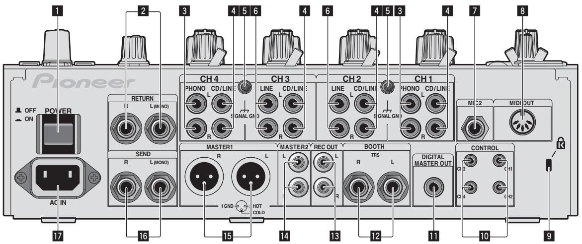
Rear panel
text_image
Pioneer OFF ON POWER 17 2 3 4 5 6 4 6 4 5 3 4 7 8 RETURN L(M NO) CH 4 PHONO CD/LIN LINE CD/LIN R S GNAL GN R CH 3 LINE CD/LIN LINE L CD/LIN R S GNAL GN R CH 2 PHONO CD/LIN R M C2 MID OUT SEND R L(MONO) MASTER1 R L 1 GND HOT COLD MASTER2 REC OUT L R TRS L R BOOTH CONTROL DIGITAL MASTER OUT C1 3 C11 C1 4 C12 91 POWER button (page 14)
Turns this unit's power on and off.
2 RETURN terminals (page 7)
Connect to the output terminal of an external effector. When the [L (MONO)] channel only is connected, the [L (MONO)] channel input is simultaneously input to the [R] channel.
3 PHONO terminals (page 7)
Connect to a phono level (MM cartridge) output device. Do not input line level signals.
To connect a device to the [PHONO] terminals, remove the short-circuit pin plug inserted in the terminals.
Insert this short-circuit pin plug into the [PHONO] terminals when nothing is connected to them to cut external noise.
4 CD/LINE terminals (page 7)
Connect to a DJ player or a line level output component.
5 SIGNAL GND terminal (page 7)
Connects an analog player's ground wire here. This helps reduce noise when the analog player is connected.
6 LINE terminals (page 7)
Connect to a cassette deck or a line level output component.
7 MIC2 terminal (page 7)
Connects a microphone here.
8 MIDI OUT terminal (page 7)
Connects this to the MIDI IN terminal on an external MIDI sequencer.
9 Kensington security slot
10 CONTROL terminal (page 7)
This is a ∅ 3.5 mm mini phone jack type DJ player control terminal. If you connect a Pioneer DJ player using a control cable (supplied with a DJ player), you can start playback of control other operations of the DJ player with the fader of this unit.
11 DIGITAL MASTER OUT terminal (page 7)
Outputs the master channel audio signals.
12 BOOTH terminals (page 7)
Output terminals for a booth monitor, compatible with balanced or unbalanced output for a TRS connector.
13 REC OUT terminals (page 7)
These are output terminals for recording.
14 MASTER2 terminals (page 7)
Connect to a power amplifier, etc.
15 MASTER1 terminals (page 7)
Connect to a power amplifier, etc.
16 SEND terminals (page 7)
Connect to the input terminal of an external effector. When the [L (MONO)] channel only is connected, a monaural audio signal is output.
17 AC IN
Connects to a power outlet using the included power cord. Wait until all connections between the equipment are completed before connecting the power cord.
Be sure to use the included power cord.
WARNING
The short-circuit pin plugs out of the reach of children and infants. If accidentally swallowed, contact a doctor immediately.
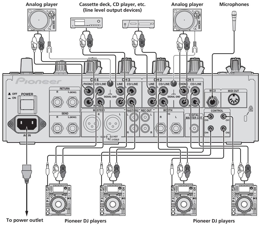
Connecting input terminals
- When creating a DVS (Digital Vinyl System) combining a computer, audio interface, etc., be careful in connecting the audio interface to this unit's input terminals and in the settings of the input selector switches.
Also refer to the operating instructions of the DJ software and audio interface.
flowchart
graph TD
    A["Analog player"] --> B["Cassette deck, CD player, etc. (line level output devices)"]
    B --> C["Analog player"]
    C --> D["Microphones"]
    D --> E["Pioneer DJ players"]
    E --> F["Pioneer DJ players"]
    A --> G["POWER ON"]
    G --> H["To power outlet"]
    H --> I["Return R L(MONO)"]
    I --> J["SEND R L(MONO)"]
    J --> K["1G 1G"]
    K --> L["2HOT 3COLD"]
    L --> M["STEL R"]
    M --> N["LINE 1"]
    N --> O["LINE 2"]
    O --> P["LINE 3"]
    P --> Q["LINE 4"]
    Q --> R["Line 1"]
    R --> S["Line 2"]
    S --> T["Line 3"]
    T --> U["Line 4"]
    U --> V["Line 5"]
    V --> W["Line 6"]
    W --> X["Line 7"]
    X --> Y["Line 8"]
    Y --> Z["Line 9"]
    Z --> AA["Line 10"]
    AA --> AB["Line 11"]
    AB --> AC["Line 12"]
    AC --> AD["Line 13"]
    AD --> AE["Line 14"]
    AE --> AF["Line 15"]
    AF --> AG["Line 16"]
    AG --> AH["Line 17"]
    AH --> AI["Line 18"]
    AI --> AJ["Line 19"]
    AJ --> AK["Line 20"]
    AK --> AL["Line 21"]
    AL --> AM["Line 22"]
    AM --> AN["Line 23"]
    AN --> AO["Line 24"]
    AO --> AP["Line 25"]
    AP --> AQ["Line 26"]
    AQ --> AR["Line 27"]
    AR --> AS["Line 28"]
    AS --> AT["Line 29"]
    AT --> AU["Line 30"]
    AU --> AV["Line 31"]
    AV --> AW["Line 32"]
    AW --> AX["Line 33"]
    AX --> AY["Line 34"]
    AY --> AZ["Line 35"]
    AZ --> BA["Line 36"]
    BA --> BB["Line 37"]
    BB --> BC["Line 38"]
    BC --> BD["Line 39"]
    BD --> BE["Line 40"]
    BE --> BF["Line 41"]
    BF --> BG["Line 42"]
    BG --> BH["Line 43"]
    BH --> BI["Line 44"]
    BI --> BJ["Line 45"]
    BJ --> BK["Line 46"]
    BK --> BL["Line 47"]
    BL --> BM["Line 48"]
    BM --> BN["Line 49"]
    BN --> BO["Line 50"]
    BO --> BP["Line 51"]
    BP --> BQ["Line 52"]
    BQ --> BR["Line 53"]
    BR --> BS["Line 54"]
    BS --> BT["Line 55"]
    BT --> BU["Line 56"]
    BU --> BV["Line 57"]
    BV --> BW["Line 58"]
    BW --> BX["Line 59"]
    BX --> BY["Line 60"]
    BY --> BZ["Line 61"]
    BZ --> CA["Line 62"]
    CA --> CB["Line 63"]
    CB --> CC["Line 64"]
    CC --> CD["Line 65"]
    CD --> CE["Line 66"]
    CE --> CF["Line 67"]
    CF --> CG["Line 68"]
    CG --> CH["Line 69"]
    CH --> CI["Line 70"]
    CI --> CJ["Line 71"]
    CJ --> CK["Line 72"]
    CK --> CL["Line 73"]
    CL --> CM["Line 74"]
    CM --> CN["Line 75"]
    CN --> CO["Line 76"]
    CO --> CP["Line 77"]
    CP --> CQ["Line 78"]
    CQ --> CR["Line 79"]
    CR --> CS["Line 80"]
    CS --> CT["Line 81"]
    CT --> CU["Line 82"]
    CU --> CV["Line 83"]
    CV --> CW["Line 84"]
    CW --> CX["Line 85"]
    CX --> CY["Line 86"]
    CY --> CZ["Line 87"]
    CZ --> DA["Line 88"]
    DA --> DB["Line 89"]
    DB --> DC["Line 90"]
• To use the fader start function, connect a control cable (page 14).
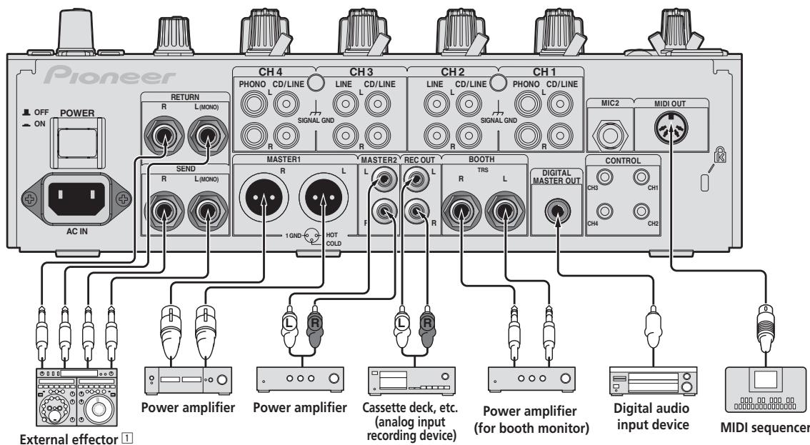
Connecting output terminals
flowchart
graph TD
    A["Pioneer"] --> B["CH 4"]
    A --> C["CH 3"]
    A --> D["CH 2"]
    A --> E["CH 1"]
    B --> F["R"]
    C --> G["L"]
    D --> H["LINE"]
    E --> I["LINE"]
    F --> J["CH4"]
    G --> K["CH3"]
    H --> L["CH2"]
    I --> M["CH1"]
    J --> N["MIC2"]
    K --> O["MIDI OUT"]
    L --> P["CH2"]
    M --> Q["MIDI OUT"]
    R["Power amplifier"] --> S["AC IN"]
    T["Power amplifier"] --> U["SEND"]
    V["Cassette deck, etc. (analog input recording device)"] --> W["F"]
    X["Digital audio input device"] --> Y["CONTROL"]
    Z["MIDI sequencer"] --> AA["External effector 1"]
1 Also connect the external effector to the [RETURN] terminal (input terminal).
Connecting to the control panel
Be sure to connect using the included USB cable.
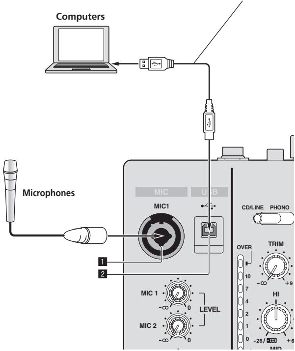
text_image
Computers Microphones MIC USB MIC1 1 2 LEVEL MIC 1 -∞ 0 MIC 2 -∞ 0 CD/LINE PHONO OVER TRIM 10 7 4 2 1 0 -26/- +6 HI MID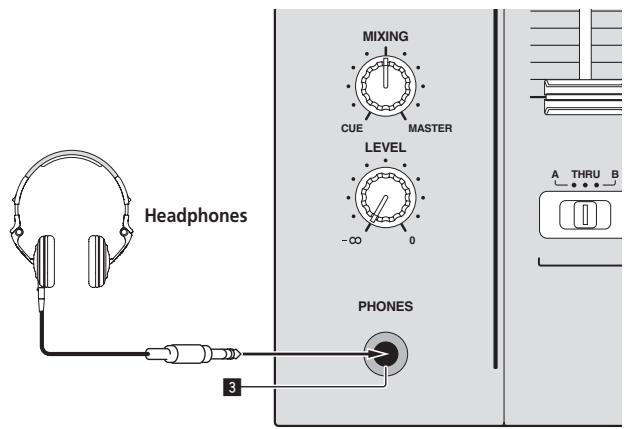
text_image
Headphones MIXING CUE MASTER LEVEL -∞ 0 PHONES 3 A THRU B1 MIC1 terminal (page 15)
Connects a microphone here.
2 USB terminal (page 10)
Connect the computer.
3 PHONES terminal (page 14)
Connect headphones here.
About the driver software and setting utility software
The driver software is required to input and output the sound of a computer using this unit's built-in USB sound card. Prepare a computer on which a Windows or Mac operating system is installed and the proprietary driver software provided by Pioneer. When the driver software is installed, the settings utility software is installed at the same time. Change the settings of the settings utility and the computer according to your environment.
Software end user license agreement
This Software End User License Agreement (“Agreement”) is between you (both the individual installing the Program and any single legal entity for which the individual is acting) (“You” or “Your”) and PIONEER CORPORATION (“Pioneer”).
TAKING ANY STEP TO SET UP OR INSTALL THE PROGRAM MEANS THAT YOU ACCEPT ALL OF THE TERMS OF THIS LICENSE AGREEMENT. PERMISSION TO DOWNLOAD AND/OR USE THE PROGRAM IS EXPRESSLY CONDITIONED ON YOUR FOLLOWING THESE TERMS. WRITTEN OR ELECTRONIC APPROVAL IS NOT REQUIRED TO MAKE THIS AGREEMENT VALID AND ENFORCEABLE. IF YOU DO NOT AGREE TO ALL OF THE TERMS OF THIS AGREEMENT, YOU ARE NOT AUTHORIZED TO USE THE PROGRAM AND MUST STOP INSTALLING IT OR UNINSTALL IT, AS APPLICABLE.
1 Definitions
1 "Documentation" means written documentation, specifications and help content made generally available by Pioneer to aid in installing and using the Program.
2 "Program" means all or any part of Pioneer's software licensed to You by Pioneer under this Agreement.
2 Program license
1 Limited License. Subject to this Agreement's restrictions, Pioneer grants to You a limited, non-exclusive, nontransferable, license (without the right to sublicense):
a To install a single copy of the Program on the hard disk drive of Your computer, to use the Program only for Your personal purpose complying with this Agreement and the Documentation ("Authorized Use");
b To use the Documentation in support of Your Authorized Use; and
c To make one copy of the Program solely for backup purposes, provided that all titles and trademark, copyright and restricted rights notices are reproduced on the copy.
2 Restrictions. You will not copy or use the Program or Documentation except as expressly permitted by this Agreement. You will not transfer, sublicense, rent, lease or lend the Program, or use it for third-party training, commercial time-sharing or service bureau use. You will not Yourself or through any third party modify, reverse engineer, disassemble or decompile the Program, except to the extent expressly permitted by applicable law, and then only after You have notified Pioneer in writing of Your intended activities. You will not use the Program on multiple processors without Pioneer's prior written consent.
3 Ownership. Pioneer or its licensor retains all right, title and interest in and to all patent, copyright, trademark, trade secret and other intellectual property rights in the Program and Documentation, and any derivative works thereof. You do not acquire any other rights, express or implied, beyond the limited license set forth in this Agreement.
4 No Support. Pioneer has no obligation to provide support, maintenance, upgrades, modifications or new releases for the Program or Documentation under this Agreement.
3 Warranty disclaimer
THE PROGRAM AND DOCUMENTATION ARE PROVIDED "AS IS" WITHOUT ANY REPRESENTATIONS OR WARRANTIES, AND YOU AGREE TO USE THEM AT YOUR SOLE RISK. TO THE FULLEST EXTENT PERMISSIBLE BY LAW, PIONEER EXPRESSLY DISCLAIMS ALL WARRANTIES OF ANY KIND WITH RESPECT TO THE PROGRAM AND
DOCUMENTATION, WHETHER EXPRESS, IMPLIED, STATUTORY, OR ARISING OUT OF COURSE OF PERFORMANCE, COURSE OF DEALING OR USAGE OF TRADE, INCLUDING ANY WARRANTIES OF MERCHANTABILITY, FITNESS FOR A PARTICULAR PURPOSE, SATISFACTORY QUALITY, ACCURACY, TITLE OR NON-INFRINGEMENT.
4 Damages and remedies for breach
You agree that any breach of this Agreement's restrictions would cause Pioneer irreparable harm for which money damages alone would be inadequate. In addition to damages and any other remedies to which Pioneer may be entitled, You agree that Pioneer may seek injunctive relief to prevent the actual, threatened or continued breach of this Agreement.
5 Termination
Pioneer may terminate this Agreement at any time upon Your breach of any provision. If this Agreement is terminated, You will stop using the Program, permanently delete it from the computer where it resides, and destroy all copies of the Program and Documentation in Your possession, confirming to Pioneer in writing that You have done so. Sections 2.2, 2.3, 2.4, 3, 4, 5 and 6 will continue in effect after this Agreement's termination.
6 General terms
Limitation of Liability. In no event will Pioneer or its subsidiaries be liable in connection with this Agreement or its subject matter, under any theory of liability, for any indirect, incidental, special, consequential or punitive damages, or damages for lost profits, revenue, business, savings, data, use, or cost of substitute procurement, even if advised of the possibility of such damages or if such damages are foreseeable. In no event will Pioneer's liability for all damages exceed the amounts actually paid by You to Pioneer or its subsidiaries for the Program. The parties acknowledge that the liability limits and risk allocation in this Agreement are reflected in the Program price and are essential elements of the bargain between the parties, without which Pioneer would not have provided the Program or entered into this Agreement.
2 The limitations or exclusions of warranties and liability contained in this Agreement do not affect or prejudice Your statutory rights as consumer and shall apply to You only to the extent such limitations or exclusions are permitted under the laws of the jurisdiction where You are located.
3 Severability and Waiver. If any provision of this Agreement is held to be illegal, invalid or otherwise unenforceable, that provision will be enforced to the extent possible or, if incapable of enforcement, deemed to be severed and deleted from this Agreement, and the remainder will continue in full force and effect. The waiver by either party of any default or breach of this Agreement will not waive any other or subsequent default or breach.
4 No Assignment. You may not assign, sell, transfer, delegate or otherwise dispose of this Agreement or any rights or obligations under it, whether voluntarily or involuntarily, by operation of law or otherwise, without Pioneer's prior written consent. Any purported assignment, transfer or delegation by You will be null and void. Subject to the foregoing, this Agreement will be binding upon and will inure to the benefit of the parties and their respective successors and assigns.
5 Entire Agreement. This Agreement constitutes the entire agreement between the parties and supersedes all prior or contemporaneous agreements or representations, whether written or oral, concerning its subject matter. This Agreement may not be modified or amended without Pioneer's prior and express written consent, and no other act, document, usage or custom will be deemed to amend or modify this Agreement.
6 You agree that this Agreement shall be governed and construed by and under the laws of Japan.
Cautions on Installation
- Before installing the driver software, be sure to turn off the power of this unit and disconnect the USB cable from both this unit and your computer.
- If you connect this unit to your computer without installing the driver software first, an error may occur on your computer depending on the system environment.
- If you have discontinued the installation process in progress, step through the installation process again from the beginning according to the following procedure.
- Read Software end user license agreement carefully before installing this unit's proprietary driver software.
- Before installing the driver software, terminate all other programs running on your computer.
• The driver software is compatible with the following OSs.
Supported operating systems
| Mac OS X 10.5 / 10.6 / 10.7 | √ | |
| Windows® 7 Home Premium/Professional/Ultimate | 32-bit version | √ |
| 64-bit version | √ | |
| Windows Vista® Home Basic/Home Premium/Business/Ultimate | 32-bit version | √ |
| 64-bit version | √ | |
| Windows® XP Home Edition/Professional (SP3 or later) | 32-bit version | √ |
Windows ^® XP Professional x64 Edition is not supported.
- The included CD-ROM includes installation programs in the following 12 languages.
English, French, German, Italian, Dutch, Spanish, Portuguese, Russian, Simplified Chinese, Traditional Chinese, Korean, and Japanese
When using operating systems in other languages, follow the instructions on the screen to select [English (English)].
Installing the driver software
◆ About the installation procedure (Windows)
Read Cautions on Installation carefully before installing the driver software.
- To install or uninstall the driver software, you need to be authorized by the administrator of your computer. Log on as the administrator of your computer before proceeding with the installation.
1 Insert the included CD-ROM into the computer's CD drive.
2 Double-click [DJM-850\_X.XXX.exe].
The driver installation screen appears.
3 When the language selection screen appears, select [English] and click [OK].
You can select one from multiple languages depending on the system environment of your computer.
4 Carefully read the Software end user license agreement and if you consent to the provisions, put a check mark in [I agree.] and click [OK].
If you do not consent to the provisions of the Software end user license agreement, click [Cancel] and stop installation.
5 Proceed with installation according to the instructions on the screen.
If [Windows Security] appears on the screen while the installation is in progress, click [Install this driver software anyway] and continue with the installation.
- When installing on Windows XP
If [Hardware Installation] appears on the screen while the installation is in progress, click [Continue Anyway] and continue with the installation. - When the installation program is completed, a completion message appears.
- When the installation of the driver software is completed, you need to reboot your computer.
◆ About the installation procedure (Mac OS X)
Read Cautions on Installation carefully before installing the driver software.
- To install or uninstall the driver software, you need to be authorized by the administrator of your computer. Have the name and password of the administrator of your computer ready in advance.
1 Insert the included CD-ROM into the computer's CD drive.
The CD-ROM folder appears.
- Double-click the CD icon on the desktop when folders are not displayed after a CD-ROM has been loaded.
2 Double-click [CD\_menu].
3 Double-click [DJM-850\_M\_X.X.X.dmg].
The [DJM-850AudioDriver] menu screen appears.
4 Double-click [DJM-850AudioDriver.pkg].
The driver installation screen appears.
5 Check the details on the screen and click [Continue Anyway].
6 When the Software Use Agreement screen appears, select [English], carefully read the Software end user license agreement and click [Continue Anyway].
You can select one from multiple languages depending on the system environment of your computer.
7 If you consent to the provisions of the Software end user license agreement, click [Agree].
If you do not consent to the provisions of the Software end user license agreement, click [I disagree] and stop installation.
8 Proceed with installation according to the instructions on the screen.
- Click [Cancel] to cancel installation after it has started.
- When the installation of the driver software is completed, you need to reboot your computer.
Connecting this unit and computer
1 Connect this unit to your computer via a USB cable.
This unit functions as an audio device conforming to the ASIO standards.
- This operation does not work with computers that do not support USB 2.0.
- When using ASIO-compatible applications, [USB 1/2], [USB 3/4], [USB 5/6] and [USB 7/8] can be used as inputs.
- When using DirectX-compatible applications, only [USB 1/2] can be used as the input.
- The computer's recommended operating environment differs according to the DJ software. Be sure to check the recommended operating environment for the DJ software you are using.
- When another USB audio device is connected to the computer at the same time, it may not operate or be recognized normally.
We recommend only connecting the computer and this unit.
- When connecting the computer and this unit, we recommend connecting directly to this unit's USB port.
2 Press [POWER] button.
Turn on the power of this unit.
- The message [Installing device driver software] may appear when this unit is first connected to the computer or when it is connected to a different USB port on the computer. Wait a while until the message [Your devices are ready for use] appears.
- When installing on Windows XP
— [Can Windows connect to Windows Update to search for software?] may appear while the installation is in progress.
Select [No, not this time], then click [Next] to continue installation.
— [What do you want the wizard to do?] may appear while the installation is in progress. Select [Install the software automatically (Recommended)], then click [Next] to continue installation.
— If [Windows Security] appears on the screen while the installation is in progress, click [Install this driver software anyway] and continue with the installation.
About the setting utility software
The setting utility can be used to make the checks and settings described below.
— Checking the status of this unit's [CD/LINE, PHONO, LINE, USB */*] selector switch
— Setting the audio data output from this unit to the computer
— Adjusting the buffer size (when using Windows ASIO)
— Checking the version of the driver software
◆ Displaying the setting utility
For Windows
Click [Start] menu > [All Programs] > [Pioneer] > [DJM-850] > [DJM-850 Settings Utility].
For Mac OS X
Click [Macintosh HD] icon > [Application] > [Pioneer] > [DJM-850] > [DJM-850 Settings Utility].
- Checking the status of this unit's [CD/LINE, PHONO, LINE, USB \*/\*] selector switch
Display the setting utility before starting.
Click the [MIXER INPUT] tab.
![PIONEER DJM-850-W - - Checking the status of this unit's [CD/LINE, PHONO, LINE, USB \*/\*] selector switch - 1](/content/2025/01/119085/images/8d18b0c8f163acd140177e7c6b4d8b8dc04e723a81f3817937153defa4585cae.jpg)
flowchart
graph TD
    A["MIXER INPUT"] --> B["Connected"]
    C["DJ/Production Software Audio Output"] --> D["Ch A:"]
    C --> E["Ch B:"]
    C --> F["Ch C:"]
    C --> G["Ch D:"]
    D --> H["Configure the audio output settings for your DJ/production software."]
    E --> H
    F --> H
    G --> H
    H --> I["USB1/2: ----→ CH1: PHONO"]
    H --> J["USB3/4: ----→ CH2: CD/LINE"]
    H --> K["USB5/6: ----→ CH3: LINE"]
    H --> L["USB7/8: ----→ CH4: PHONO"]
    I --> M["To input a USB audio signal to the mixer, select "USB" for the desired channel input selector switch(es) on the mixer."]
    J --> M
    K --> M
    L --> M
Setting the audio data output from this unit to the computer
Display the setting utility before starting.
1 Click the [MIXER OUTPUT] tab.
![PIONEER DJM-850-W - Click the [MIXER OUTPUT] tab. - 1](/content/2025/01/119085/images/93984840ffc21fa08e53ab1cc25b4f5e74e172d52c19fe30aa059e53dc70a174.jpg)
flowchart
graph TD
    A["DJ/Production Software Audio Input"] --> B["Connected"]
    B --> C["Mixer Audio Output"]
    C --> D["USB1/2: Post CH1 Fader"]
    C --> E["USB3/4: Post CH2 Fader"]
    C --> F["USB5/6: Post CH3 Fader"]
    C --> G["USB7/8: Post CH4 Fader"]
    H["Configure the audio input settings for your DJ/production software."] --> I["Ch A:"]
    H --> J["Ch B:"]
    H --> K["Ch C:"]
    H --> L["Ch D:"]
2 Click the [Mixer Audio Output] pull-down menu.
Select and set the audio data to be output to the computer from the flow of audio signals inside this unit.
| CH1 | CH2 | CH3 | CH4 |
| CH1 Timecode PHONO^1 | CH2 Timecode CD/LINE^1 | CH3 Timecode CD/LINE^1 | CH4 Timecode PHONO^1 |
| CH1 Timecode CD/LINE^1 | CH2 Timecode LINE^1 | CH3 Timecode LINE^1 | CH4 Timecode CD/LINE^1 |
| Post CH1 Fader ^2 | Post CH2 Fader ^2 | Post CH3 Fader ^2 | Post CH4 Fader ^2 |
| Cross Fader A^2 | Cross Fader A^2 | Cross Fader A^2 | Cross Fader A^2 |
| Cross Fader B^2 | Cross Fader B^2 | Cross Fader B^2 | Cross Fader B^2 |
| MIC | MIC | MIC | MIC |
| REC OUT ^2 | REC OUT ^2 | REC OUT ^2 | REC OUT ^2 |
| None | None | None | None |
The audio data is output with the same volume at which it is input to this unit, regardless of the [USB Output Level] setting.
② When using for any purposes other than sound recording, pay attention to set the DJ software so that sound loops are not generated. If sound loops are generated, sound with an unintended volume might be input or output.
3 Click the [USB Output Level] pull-down menu.
Adjust the volume of the audio data output from this unit.
- The [USB Output Level] setting is applied equally to all audio data. However, when 1 on the table at step 2 is selected, the audio data is output with the same volume at which it is input to this unit.
- If not enough volume can be achieved with the DJ software's volume adjustment alone, change the [USB Output Level] setting to adjust the volume of the audio data output from this unit. Note that the sound will be distorted if the volume is raised too high.
❖ Adjusting the buffer size (when using Windows ASIO)
If an application using this unit as the default audio device (DJ software, etc.) is running, quit that application before adjusting the buffer size. Display the setting utility before starting.
Click the [ASIO] tab.
![PIONEER DJM-850-W - Click the [ASIO] tab. - 1](/content/2025/01/119085/images/eadddc7b7bd835369e30e779363f5745430eda5d9e3dd4bcea5e65ff76645cee.jpg)
text_image
DJM-850 Setting Utility MIXER INPUT MIXER OUTPUT ASIO About Sets the size of the buffer when using ASIO. If you make the buffer smaller or select a high sampling rate with the DJ software, then latency (Audio output delay) will be shorter. If the audio gets cut off, increase the size of the buffer or reduce the sampling rate with the DJ software so that the sound does not get cut off. Sampling Rate 44100Hz 48000Hz 96000Hz Buffer Size 256 Sample Latency 2.6msec Standard Setting- If the buffer size is made large, drops in audio data (breaks in the sound) occur less easily, but the time lag due to the delay in the transfer of the audio data (latency) increases.
- Checking the version of the driver software
Display the setting utility before starting.
Click the [About] tab.
![PIONEER DJM-850-W - Click the [About] tab. - 1](/content/2025/01/119085/images/7f3471fa6f665982541ce6a570fd569a06a4ad9073c5451896fac79e2779823e.jpg)
text_image
DJM-850 Setting Utility MIXER INPUT MIXER OUTPUT ASIO About DJM-850 Setting Utility Version : 1.000 Copyright © 2012 Pioneer CorporationChecking the latest information on the driver software
For the latest information on the driver software for exclusive use with this unit, visit our website shown below. http://pioneerdj.com/support/
- Operation cannot be guaranteed when multiple units of this mixer are connected to a single computer.
Operation
text_image
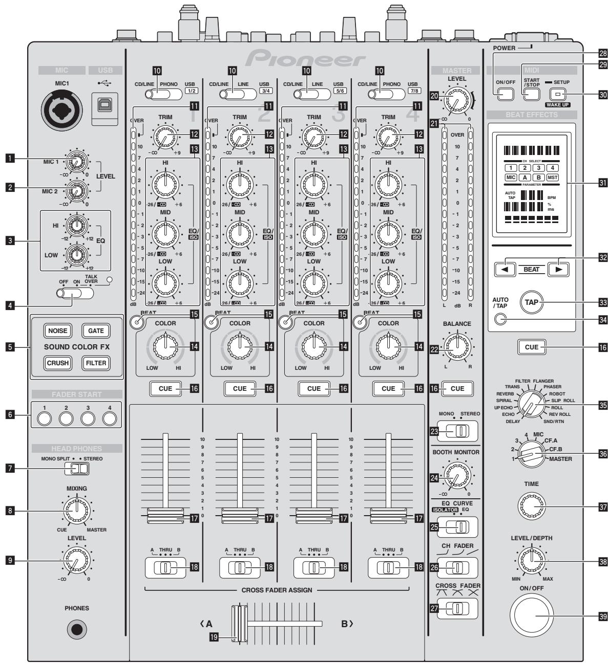
Pioneer MIC USB 10 CD/LINE PHONO USB 1/2 11 VER 10 -∞ +9 13 HI 26/ISO +6 MID 26/ISO +6 EQ/ISO LOW 26/ISO +6 dB OFF ON TALK OVER 0 1 2 3 4 5 6 7 8 9 10 11 12 13 14 15 16 17 18 19 20 21 22 23 24 25 26/ISO +6 dB CUE 15 BEAT COLOR LOW HI 14 CUE 16 BEAT COLOR LOW HI 15 CUE 16 BEAT COLOR LOW HI 15 CUE 16 BEAT COLOR LOW HI 15 CUE 16 BEAT COLOR LOW HI 15 CUE 16 BEAT COLOR LOW HI 15 CUE 16 BEAT COLOR LOW HI 15 CUE 16 BEAT COLOR LOW HI PIONEER MASTER LEVEL 20 21 22 23 24 25 26 27 28 29 30 31 32 33 34 35 36 37 38 39 POWER —— 28 MIDI ON/OFF START/STOP SETUP WAKE UP BEAT EFFECTS AUTO / TAP TAP CUE FILTER FLANGER TRANS REVERB SPIRAL UP ECHO ECHO DELAY MULTIC CF.A CF.B MASTER TIME LEVEL/DEPTH MIN MAX ON/OFF CROSS FADER BEAT START HEAD PHONES MONO SPLIT + STEREO MIXING LEVEL PHONES < A > 19 B>1 MIC1 LEVEL control (page 15)
Adjusts the sound level output from the [MIC1] channel.
2 MIC2 LEVEL control (page 15)
Adjusts the sound level output from the [MIC2] channel.
3 EQ (HI, LOW) controls (page 15)
These adjust the tone quality of the [MIC1] and [MIC2] channels.
4 OFF, ON, TALK OVER selector switch (page 15)
Turns the microphone on/off.
5 SOUND COLOR FX buttons (page 16)
These turn the SOUND COLOR FX effects on/off.
6 FADER START (1, 2, 3, 4) buttons (page 14)
These turn the fader start function on/off.
7 MONO SPLIT, STEREO selector switch (page 14)
Switches how the monitor sound output from the headphones is distributed.
8 MIXING control (page 14)
This adjusts the monitor volume balance of the sound of channels for which the [CUE] button is pressed and the sound of the [MASTER] channel.
9 LEVEL control (page 14)
Adjusts the sound level output from the headphones.
10 CD/LINE, PHONO, LINE, USB */* selector switch (page 14)
Selects the input source of each channel from the components connected to this unit.
11 Channel Level Indicator (page 14)
Displays the sound level of the respective channels before passing through the channel faders.
12 TRIM control (page 14)
Adjusts the level of audio signals input in each channel.
13 EQ/ISO (HI, MID, LOW) controls (page 14)
These adjust the sound quality of the respective channels.
14 COLOR control (page 16)
This changes the parameters of the SOUND COLOR FX of the different channels.
15 BEAT button (page 16)
When the button is pressed while SOUND COLOR FX is turned on, the effect sound is associated to the beat (change in volume) of the currently playing track.
16 CUE button (page 14)
Presses the [CUE] button(s) for the channel(s) you want to monitor.
17 Channel Fader (page 14)
Adjusts the level of audio signals output in each channel.
18 CROSS FADER ASSIGN (A, THRU, B) selector switch (page 14)
Sets the output destination of each channel to [A] or [B].
19 Crossfader (page 14)
Outputs audio signals assigned by the crossfader assign switch corresponding to the curve characteristics selected by [CROSS FADER] (Crossfader Curve Selector Switch).
20 MASTER LEVEL control (page 14)
Adjusts the sound level output from the [MASTER] channel.
21 Master Level Indicator (page 14)
Displays the sound level output from the [MASTER] channel.
22 BALANCE control (page 15)
Adjusts the left/right balance of the sound output from the [MASTER1] terminals, etc.
23 MONO, STEREO selector switch (page 15)
Switches the sound output from the [MASTER1] terminals, etc., between monaural and stereo.
24 BOOTH MONITOR control (page 15)
Adjusts the level of audio signals output from the [BOOTH] terminal.
25 EQ CURVE (ISOLATOR, EQ) selector switch (page 14)
Switches the function of the [EQ/ISO (HI, MID, LOW)] controls.
26 CH FADER (-, -, /) selector switch (page 14)
Switches the channel fader's curve characteristics.
27 CROSS FADER ( × , × , × ) selector switch (page 14)
This switches the crossfader curve characteristics.
28 ON/OFF button (page 17)
Switches the MIDI function on and off.
29 START/STOP button (page 17)
Sends the MIDI start/MIDI stop signals.
30 SETUP (WAKE UP) button (page 23)
— SETUP: Displays the [USER SETUP] or [CLUB SETUP] screen.
— WAKE UP: Cancels the auto standby mode.
31 Main unit display
32 BEAT ◀, ▶ buttons (page 16)
Set the beat fraction for synchronizing the effect sound.
33 TAP (ENTER) button
— TAP: When the BPM measurement mode is set to [TAP], the BPM is input manually by tapping the button with a finger (page 16).
— ENTER: Used to change this unit's settings (page 23).
34 AUTO/TAP button (page 16)
Switches the BPM measurement mode.
35 DELAY, ECHO, UP ECHO, SPIRAL, REVERB, TRANS, FILTER, FLANGER, PHASER, ROBOT, SLIP ROLL, ROLL, REV ROLL, SND/RTN selector switch (page 16)
Switches the BEAT EFFECT effect type.
36 1, 2, 3, 4, MIC, CF.A, CF.B, MASTER selector switch (page 16)
Switches the channel to which the BEAT EFFECT is to be applied.
37 TIME control (page 16)
Adjusts the BEAT EFFECT's time parameter.
38 LEVEL/DEPTH control (page 16)
Adjusts the BEAT EFFECT's quantitative parameter.
39 ON/OFF button (page 16)
Turns the BEAT EFFECT function on/off.
Do not pull on the channel fader and crossfader knobs with excessive force. The knobs have a structure by which they cannot be pulled off easily. Pulling the knobs strongly may result in damaging the unit.
Basic Operation
Outputting sound
1 Press [POWER] button.
Turns on the power of this unit.
2 Switch the [CD/LINE, PHONO, LINE, USB \*/\*] selector switch.
Selects the input sources for the different channels from among the devices connected to this unit.
— [PHONO]: Selects the analog player connected to the [PHONO] terminals.
— [CD/LINE], [LINE]: Selects the DJ player or cassette deck connected to the [CD/LINE] or [LINE] terminals.
— [USB */*]: Selects the sound of the computer connected to the [USB] port.
3 Turn the [TRIM] control.
Adjusts the level of audio signals input in each channel.
The corresponding channel level indicator lights when audio signals are being properly input to that channel.
4 Move the channel fader away from you.
Adjusts the level of audio signals output in each channel.
5 Switch the [CROSS FADER ASSIGN (A, THRU, B)] selector switch.
Switches the output destination of each channel.
— [A]: Assigns to [A] (left) of the crossfader.
— [B]: Assigns to [B] (right) of the crossfader.
— [THRU]: Selects this when you do not want to use the crossfader. (The signals do not pass through the crossfader.)
6 Set the crossfader.
This operation is not necessary when the [CROSS FADER ASSIGN (A, THRU, B)] selector switch is set to [THRU].
7 Turn the [MASTER LEVEL] control.
Audio signals are output from the [MASTER1] and [MASTER2] terminals.
The master level indicator lights.
Adjusting the sound quality
Turn the [EQ/ISO (HI, MID, LOW)] controls for the respective channels.
Refer to Specifications on page 27 for the range of sound that can be adjusted by each control.
❖ Switching the function of the [EQ/ISO (HI, MID, LOW)] controls
Switch the [EQ CURVE (ISOLATOR, EQ)] selector switch.
— [ISOLATOR]: Functions as an isolator.
— [EQ]: The equalizer function is set.
Monitoring sound with headphones
1 Connect headphones to the [PHONES] terminal.
2 Press the [CUE] button(s) for the channel(s) you want to monitor.
3 Switch the [MONO SPLIT, STEREO] selector switch.
— [MONO SPLIT]: The sound of the channels for which the [CUE] button is pressed is output from the headphones output's left
channel, the [MASTER] channel sound is output from the right channel.
— [STEREO]: The sound of the channels for which the [CUE] button is pressed is output from the headphones in stereo.
4 Turn the [MIXING] control.
This adjusts the monitor volume balance of the sound of channels for which the [CUE] button is pressed and the sound of the [MASTER] channel.
5 Turn the [LEVEL] control for [HEADPHONES].
The sound of the channels for which the [CUE] button is pressed is output from the headphones.
- When the [CUE] button is pressed again, monitoring is canceled.
Switching the fader curve
- Select the channel fader curve characteristics.
Switch the [CH FADER (∼, ∼, ∽)] selector switch.
— [√]: The curve rises suddenly at the back side.
— [√]: A curve between the ones above and below is set.
— [√]: The curve rises gradually (the sound gradually increases as the channel fader is moved away from the front side).
- Select the crossfader curve characteristics.
Switch the [CROSS FADER ( , × , × )] selector switch.
— [✗]: Makes a sharply increasing curve (if the crossfader is moved away from the [A] side, audio signals are immediately output from the [B] side).
— [X]: Makes a curve shaped between the two curves above and below.
— [X]: Makes a gradually increasing curve (if the crossfader is moved away from the [A] side, the sound on the [B] side gradually increases, while the sound on the [A] gradually decreases).
Starting playback on a DJ player using the fader (fader start)
If you connect a Pioneer DJ player using a control cable (supplied with a DJ player), you can start playback of control other operations of the DJ player with the fader of this unit.
Connect this unit and Pioneer DJ player beforehand. For instructions on connections, see Connecting input terminals on page 7.
The fader start function can be switched on and off for all DJ players all at once. For the switching procedure, see Changing the settings on page 23.
- Start playback using the channel fader
1 Set the [CROSS FADER ASSIGN (A, THRU, B)] selector switch to [THRU].
2 Press one of the [FADER START (1, 2, 3, 4)] buttons.
Select the channel to be started with the fader start function.
3 Set the channel fader to the nearest position towards you.
4 Set the cue on the DJ player.
The DJ player pauses playback at the cue point.
5 Move the channel fader away from you.
Playback starts on the DJ player.
- If you set the channel fader back to the original position, the player instantaneously returns to the cue point already set and pauses playback (back cue).
- Start playback using the crossfader
1 Set the [CROSS FADER ASSIGN (A, THRU, B)] selector switch to [A] or [B].
2 Press one of the [FADER START (1, 2, 3, 4)] buttons.
Select the channel to be started with the fader start function.
3 Set the crossfader.
Set to the edge opposite the side on which the channel you want to use with the fader start function is set.
4 Set the cue on the DJ player.
The DJ player pauses playback at the cue point.
5 Set the crossfader.
Playback starts on the DJ player.
- If you set the crossfader back to the original position, the player instantaneously returns to the cue point already set and pauses playback (back cue).
Using a microphone
1 Connect a microphone to the [MIC1] or [MIC2] terminal.
2 Set the [OFF, ON, TALK OVER] selector switch to [ON] or [TALK OVER].
— [ON]: The indicator lights.
— [TALK OVER]: The indicator flashes.
- When set to [TALK OVER], the sound of channels other than the [MIC] channel is attenuated by 18 dB (default) when a sound of -10 dB or greater is input to the microphone.
- The [TALK OVER] sound attenuation level can be changed at [USER SETUP] screen. For instructions on changing this, see Changing the settings on page 23.
- The talk over mode can be switched to the normal mode or the advanced mode. For instructions on changing it, see Changing the settings on page 23.
3 Turn the [MIC1 LEVEL] or [MIC2 LEVEL] control.
Adjust the level of the sound output from the [MIC] channel.
- Pay attention that rotating to the extreme right position outputs a very loud sound.
4 Input audio signals to the microphone.
◆ Adjusting the sound quality
Turn the [MIC] channels' [EQ (HI, LOW)] controls.
Refer to Specifications on page 27 for the range of sound that can be adjusted by each control.
Switching between monaural and stereo audio
This switches the sound output from the [MASTER1], [MASTER2], [BOOTH], [REC OUT], [PHONES], [DIGITAL MASTER OUT] and [USB] terminals between monaural and stereo.
- To adjust the sound output from the [USB] terminals, select [REC OUT] at [Mixer Audio Output] in the setting utility.
Switch the [MONO, STEREO] selector switch.
— [MONO]: Outputs monaural audio.
— [STEREO]: Outputs stereo audio.
◆ Adjusting the L/R balance of audio
The left/right balance of the sound output from the [MASTER1],
[MASTER2], [BOOTH], [REC OUT], [PHONES], [DIGITAL MASTER OUT] and [USB] terminals can be adjusted.
- To adjust the sound output from the [USB] terminals, select [REC OUT] at [Mixer Audio Output] in the setting utility.
1 Set the [MONO, STEREO] selector switch to [STEREO].
2 Turn the [BALANCE] control.
The sound's left/right balance changes according to the direction in which the [BALANCE] control is turned and its position. - Rotating to the rightmost position outputs only the right sound of stereo audio. Rotating to the leftmost position outputs only the left sound of stereo audio.
Audio is output from the [BOOTH] terminal
Turn the [BOOTH MONITOR] control.
Adjusts the level of audio signals output from the [BOOTH] terminal.
Advanced Operations
SOUND COLOR FX
These effects change in association with the [COLOR] controls for the different channels.
1 Press one of the [SOUND COLOR FX] buttons.
This selects the type of effect.
The button that was pressed flashes.
- For the types of effects, see BEAT COLOR FX/SOUND COLOR FX effect types on page 18.
• The same effect is set for [CH1] to [CH4].
2 Turn the [COLOR] control.
The effect is applied to the channel(s) for which the control(s) was (were) pressed.
BEAT COLOR FX
The SOUND COLOR FX effect can be associated to the beat (change in volume) of the track when the [BEAT] buttons for the respective channels are pressed. The beat association function can be set separately for the respective channels.
The following describes the operating procedure for when SOUND COLOR FX is turned on.
Press the [BEAT] button.
The beat association function is turned on for the channel(s) whose [BEAT] button(s) was (were) pressed.
The SOUND COLOR FX effect is associated to the track's beat.
- When the [BEAT] button is pressed again, the beat association function is turned off.
- The beat association function can also be used by turning SOUND COLOR FX on after pressing the [BEAT] button.
BEAT EFFECT
flowchart
graph TD
    A["1"] --> B["CH SELECT"]
    C["2"] --> B
    D["3"] --> E["AUTO TAP"]
    F["4"] --> E
    G["5"] --> H["BPM % ms"]
    I["6"] --> H
    J["7"] --> H
    B --> K["MIC"]
    B --> L["A"]
    B --> M["B"]
    B --> N["MST"]
    E --> O["A"]
    E --> P["B"]
    E --> Q["BPM"]
    H --> R["% ms"]
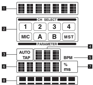
This function lets you instantaneously set various effects according to the tempo (BPM = Beats Per Minute) of the currently playing track.
| 1 | Effect display section | The name of the selected effect is displayed. |
| 2 | Channel select display section | The name of the channel to which the effect is applied is displayed. |
| 3 | AUTO (TAP) | [AUTO] lights when the BPM measurement mode is set to the auto mode.[TAP] lights when in the manual input mode. |
| 4 | BPM value display (3 digits) | When in the auto mode, this displays the automatically detected BPM value.When the BPM cannot be detected, the previously detected BPM value is displayed and flashes.When in the manual input mode, this displays the BPM value that was input manually. |
| 5 | BPM | This is always lit. |
| 6 | Parameter display section | This displays the parameters specified for the individual effects.When the [BEAT ◀, ▶] button is pressed, the corresponding beat fraction is displayed for 1 second.When a value outside the parameter range is specified with the [BEAT ◀, ▶] button, the value does not change and the display flashes. |
| 7 | % (ms) | These light according to the units for the different effects. |
| 8 | Beat display section | This lights according to the selected beat number position. |
1 Press [AUTO/TAP] button.
Select the BPM measurement mode.
— [AUTO]: The BPM is measured automatically from the audio signal that is being input. The [AUTO] mode is set when this unit's power is turned on.
— [TAP]: The BPM is input manually by tapping the [TAP] button with a finger.
- The [AUTO] BPM measurement range is BPM = 70 to 180. With some tracks it may not be possible to measure the BPM correctly. If the BPM cannot be measured, the BPM value on the display flashes. In such cases, use the [TAP] button to input the BPM manually.
2 Turn the [DELAY, ECHO, UP ECHO, SPIRAL, REVERB, TRANS, FILTER, FLANGER, PHASER, ROBOT, SLIP ROLL, ROLL, REV ROLL, SND/RTN] selector switch.
This selects the type of effect.
- For the types of effects, see Types of BEAT EFFECT on page 18.
• To use [SND/RTN], see Using the external effector below.
3 Turn the [1, 2, 3, 4, MIC, CF.A, CF.B, MASTER] selector switch.
This selects the channel to which the effect is applied.
— [1] – [4]: The effect is applied to the sound of the respective channel.
— [MIC]: The effect is applied to the sound of [MIC] channel.
— [CF.A], [CF.B]: The effect is applied to the sound of the cross-fader's [A] (left) or [B] (right) side.
— [MASTER]: The effect is applied to the sound of the [MASTER] channel.
4 Press the [BEAT ◀, ▶] button.
Set the beat fraction for synchronizing the effect sound.
The effect time corresponding to the beat fraction is set automatically.
5 Press the [ON/OFF] button for [BEAT EFFECTS].
The effect is applied to the sound.
The effect's time parameter can be adjusted by turning the [TIME] control.
The effect's quantitative parameter can be adjusted by turning the [LEVEL/DEPTH] control.
The [ON/OFF] button flashes when the effect is on.
- When the [ON/OFF] button is pressed again, the effect turns off.
Inputting the BPM manually
Tap the [TAP] button at least 2 times in rhythm with the beat (in quarter notes) of the sound being played.
The average value of the interval at which the [TAP] button was tapped by finger is set as the BPM.
- When the BPM is set using the [TAP] button, the beat fraction is set to [1/1] and the time of one beat (quarter note) is set as the effect time.
- The BPM can be set manually by turning the [TIME] control while pressing the [TAP] button.
- The BPM can be set in units of 0.1 by pressing the [AUTO/TAP] button while pressing the [TAP] button and turning the [TIME] control while pressing the two buttons.
◆ Using the external effector
1 Connect this unit and external effector.
For instructions on connections, see Connecting output terminals on page 7.
2 Turn the [DELAY, ECHO, UP ECHO, SPIRAL, REVERB, TRANS, FILTER, FLANGER, PHASER, ROBOT, SLIP ROLL, ROLL, REV ROLL, SND/RTN] selector switch.
Select [SND/RTN].
3 Turn the [1, 2, 3, 4, MIC, CF.A, CF.B, MASTER] selector switch.
This selects the channel to which the effect is applied.
4 Press the [ON/OFF] button for [BEAT EFFECTS].
The sound that has passed through the external effector is output from the [MASTER] channel.
- When the [ON/OFF] button is pressed again, the effect turns off.
Operating DJ software using the MIDI function
This unit is equipped with a "Full Assignable MIDI" function allowing the operation information of virtually all of the unit's controls and buttons to be sent to the DJ software as MIDI signals. This unit can be used as a USB MIDI controller when it is connected by USB cable to a computer on which MIDI-compatible DJ software is installed. Furthermore, the tempo (BPM) of the sound being played is sent as MIDI timing clocks, so the tempo on the DJ software can be synchronized with the tempo of the sound output from this unit.
To operate DJ software with this unit, first install the MIDI-compatible DJ software on the computer. The MIDI-related settings must also be made on the DJ software.
- For the messages output by this unit, see List of MIDI Messages on page 21.
- If you want to change this unit's MIDI channel, see Changing the settings on page 23.
1 Connect this unit's [USB] terminal to the computer.
For details about connections, see Connecting to the control panel on page 8.
2 Launch the DJ software.
3 Press the [MIDI] [ON/OFF] button.
Turn the MIDI function on.
Transmission of the MIDI messages begin.
- When a fader or control is moved, a message corresponding to the position is sent.
- When the [START/STOP] button is pressed and held in for more than 2 seconds, a set of MIDI messages corresponding to the button, fader or control positions is sent (Snapshot).
- When the [ON/OFF] button for [MIDI] is pressed again, transmission of MIDI messages stops.
- The MIDI timing clocks (BPM information) are sent regardless of the [MIDI] [ON/OFF] button's setting.
- Sending the MIDI start and MIDI stop messages
Press the [START/STOP] button for [MIDI].
- The MIDI start and MIDI stop messages are sent alternatively each time the [START/STOP] button is pressed, regardless of whether the MIDI function is on or off.
Operating an external MIDI sequencer
This unit is equipped with a “Full Assignable MIDI” function allowing the operation information of virtually all of the unit’s controls and buttons to be sent to an external device (effector, etc.) as MIDI signals. This unit can be used as a USB MIDI controller when it is connected by MIDI cable to a MIDI-compatible external device. Furthermore, the tempo (BPM) of the sound being played is sent as MIDI timing clocks, so the tempo on the external device (sequencer, etc.) can be synchronized with the tempo of sound output from this unit.
- For the messages output by this unit, see List of MIDI Messages on page 21.
- External MIDI sequencers not supporting MIDI timing clocks cannot be synchronized.
- External MIDI sequencers cannot be synchronized for sources for which the BPM cannot be measured stably.
- The MIDI timing clock is output even with BPM values input manually by tapping the [TAP] button with a finger. The MIDI timing clock output range is 40 BPM to 250 BPM.
1 Connect the [MIDI OUT] terminal to the external MIDI sequencer's MIDI IN terminal using a commercially available MIDI cable.
2 Set the external MIDI sequencer's sync mode to Slave.
3 Press the [START/STOP] button for [MIDI].
The MIDI start message is sent.
4 Press the [MIDI] [ON/OFF] button.
Transmission of the MIDI messages begin.
Types of effects
BEAT COLOR FX/SOUND COLOR FX effect types
| Effect Name | [BEAT] button status | Descriptions | [COLOR] control |
| NOISE | Off | White noise generated inside this unit is mixed in to the sound of the channel via the filter and output.The volume can be adjusted by turning the [TRIM] controls for the respective channels. The sound quality can be adjusted by turning the [EQ/ISO (HI, MID, LOW)] controls. | Turn counterclockwise: The cut-off frequency of the filter through which the white noise passes gradually decreases.Turn clockwise: The cut-off frequency of the filter through which the white noise passes gradually increases. |
| On | The volume changes in association with the beat. | Turn counterclockwise: The cut-off frequency of the filter through which the white noise passes gradually decreases.Turn clockwise: The cut-off frequency of the filter through which the white noise passes gradually increases. | |
| GATE | Off | The gate effect makes the sound tighter and reduces the sense of volume. | Turn counterclockwise: The gate effect is applied to the medium and high frequencies.Turn clockwise: The gate effect is applied to the low and high frequencies. |
| On | The sound is recorded while the gate is open, and when the gate is closed, the recorded sound is output several times. | Turn counterclockwise: The gate effect is applied to the medium and high frequencies, and the sampled sound is added.Turn clockwise: The gate effect is applied to the low and high frequencies, and the sampled sound is added. | |
| CRUSH | Off | Changes the original sound to a crushed-like sound for output. | Turn counterclockwise: Increases the sound's distortion.Turn clockwise: The sound is crushed before passing through the high pass filter. |
| On | The distortion changes in association with the beat. | Turn counterclockwise: Increases the sound's distortion.Turn clockwise: The sound is crushed before passing through the high pass filter. | |
| FILTER | Off | Outputs sound that has passed through a filter. | Turn counterclockwise: Gradually decreases the low-pass filter's cutoff frequency.Turn clockwise: Gradually increases the high-pass filter's cutoff frequency. |
| On | The filter's cut-off frequency changes in association with the beat. | Turn counterclockwise: Gradually decreases the low-pass filter's cutoff frequency.Turn clockwise: Gradually increases the high-pass filter's cutoff frequency. |
Types of BEAT EFFECT
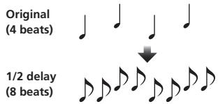
DELAY ^1
A delay sound is output once according to the beat fraction set with the [BEAT ◀, ▶] buttons.
When 1/2 beat delay sound is added, 4 beats become 8 beats.
text_image
Original (4 beats) ↓ 1/2 delay (8 beats)| BEAT ◀, ► buttons (parameter 1) | Use these to set a time delay of 1/8 - 16/1 with respect to the time of one beat of the BPM. |
| TIME control (parameter 2) | Use this to set the delay time.1 to 4000 (ms) |
| LEVEL/DEPTH control (parameter 3) | Use this to set the balance between the original sound and the delay sound. |
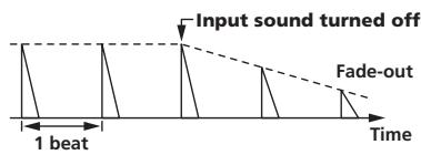
ECHO ^1 2
A delay sound is output several times and gradually attenuated according to the beat fraction set with the [BEAT ◀, ▶] buttons.
With 1/1 beat echoes, the delay sounds are faded out according to the track's tempo even after the input sound has been cut.
text_image
Input sound turned off Fade-out 1 beat Time| BEAT ◀, ► buttons (parameter 1) | Use these to set a time delay of 1/8 – 16/1 with respect to the time of one beat of the BPM. |
| TIME control (parameter 2) | Use this to set the delay time.1 to 4000 (ms) |
| LEVEL/DEPTH control (parameter 3) | Use this to set the balance between the original sound and the echo sound. |
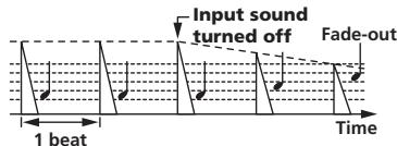
UP ECHO ^1 ^2
A delay sound is output several times and gradually attenuated according to the beat fraction set with the [BEAT ◀, ▶] buttons.
With 1/1 beat echoes, the delay sounds are faded out according to the track's tempo even after the input sound has been cut.
Also, it is also possible to change the pitch of the echo sound.
text_image
Input sound turned off Fade-out 1 beat Time| BEAT ◀, ► buttons (parameter 1) | Use these to set a time delay of 1/8 - 16/1 with respect to the time of one beat of the BPM. |
| TIME control (parameter 2) | Use this to set the delay time. 1 to 4000 (ms) |
| LEVEL/DEPTH control (parameter 3) | Use this to set the balance between the original sound and the echo sound and to set the amount by which the echo sound’s pitch changes. |
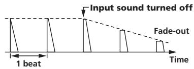
SPIRAL ^1 ^2
This function adds a reverberation effect to the input sound.
When the delay time is changed, the pitch changes simultaneously.
text_image
Input sound turned off Fade-out 1 beat Time| BEAT ◀, ► buttons (parameter 1) | Use these to set a time delay of 1/8 - 16/1 with respect to the time of one beat of the BPM. |
| TIME control (parameter 2) | Use this to set the delay time. 10 to 4000 (ms) |
| LEVEL/DEPTH control (parameter 3) | Use this to set the balance between the original sound and the effect sound and to set the quantitative parameter. |
REVERB ^1 2
This function adds a reverberation effect to the input sound.
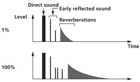
bar
| Time Period | Level | Event Type | |-------------|-------|------------------------| | Top Left | 1% | Direct sound | | Top Right | 100% | Early reflected sound || BEAT ◀, ► buttons (parameter 1) | Use these to set the extent of the reverberation effect, from 1 – 100 %. |
| TIME control (parameter 2) | Use this to set the degree of the reverb effect. 1 – 100 (%) |
| LEVEL/DEPTH control (parameter 3) | Use this to set the balance between the original sound and the effect sound and to set the cut-off frequency of the filter through which the effect sound passes. |
TRANS ^1
The sound is cut according to the beat fraction set with the [BEAT ◀, ▶] buttons.
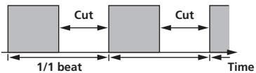
text_image
Cut 1/1 beat Cut Time| BEAT ◀, ► buttons (parameter 1) | Use these to set a cut time of 1/16 – 16/1 with respect to the time of one beat of the BPM. |
| TIME control (parameter 2) | Use this to set the effect time.10 to 16000 (ms) |
| LEVEL/DEPTH control (parameter 3) | Sets the balance between the original sound and the effect sound. |
FILTER ^1
The filter's cutoff frequency changes according to the beat fraction set with the [BEAT ◀, ▶] buttons.
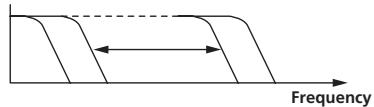
text_image
Frequency| BEAT ◀, ► buttons (parameter 1) | Use these to set the cycle for moving the cut-off frequency as a time of 1/4 - 64/1 with respect to the time of one beat of the BPM. |
| TIME control (parameter 2) | Use this to set the cycle at which the cut-off frequency is moved.10 to 32000 (ms) |
| LEVEL/DEPTH control (parameter 3) | The further the control is turned clockwise, the more the effect is stressed. |
FLANGER ^1
A 1-cycle flanger effect is produced according to the beat fraction set with the [BEAT ◀, ▶] buttons.
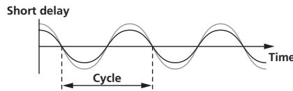
text_image
Short delay Cycle Time| BEAT ◀, ► buttons (parameter 1) | Use these to set the 1/4 - 64/1 effect time with respect to the time of one beat of the BPM. |
| TIME control (parameter 2) | Use this to set the cycle by which the flanger effect moves.10 to 32000 (ms) |
| LEVEL/DEPTH control (parameter 3) | The further the control is turned clockwise, the more the effect is stressed.When turned all the way counterclockwise, only the original sound is output. |
PHASER ^1
The phaser effect changes according to the beat fraction set with the [BEAT ◀, ▶] buttons.
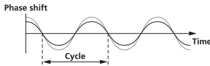
text_image
Phase shift Cycle Time| BEAT ▶,▶ buttons (parameter 1) | Use these to set the cycle for moving the phaser effect as of time of 1/4 - 64/1 with respect to the time of one beat of the BPM. |
| TIME control (parameter 2) | This sets the cycle by which the phaser effect is moved. 10 to 32000 (ms) |
| LEVEL/DEPTH control (parameter 3) | The further the control is turned clockwise, the more the effect is stressed.When turned all the way counterclockwise, only the original sound is output. |
ROBOT ^1
The original sound is changed to a sound like one produced by a robot.
| BEAT ◀, ► buttons (parameter 1) | Use these to set the degree of the effect sound, from -100 – 100 %. |
| TIME control (parameter 2) | Use this to set the degree of the effect sound. -100–100 (%) |
| LEVEL/DEPTH control (parameter 3) | Sets the balance between the original sound and the effect sound. |
SLIP ROLL ^1 ^2
The sound being input at the point when the [ON/OFF] is pressed is recorded, and the recorded sound is output repeatedly according to the beat fraction set with the [BEAT ◀, ▶] buttons.
When the effect time changes, the input sound is recorded again.
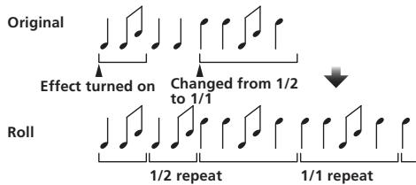
text_image
Original Effect turned on Changed from 1/2 to 1/1 Roll 1/2 repeat 1/1 repeat| BEAT ◀, ► buttons (parameter 1) | Use these to set an effect time of 1/16 - 16/1 with respect to the time of one beat of the BPM. |
| TIME control (parameter 2) | Use this to set the effect time. 10 to 4000 (ms) |
| LEVEL/DEPTH control (parameter 3) | Use this to set the balance between the original sound and ROLL. |
ROLL ^1 ^2
The sound being input at the point when the [ON/OFF] is pressed is recorded, and the recorded sound is output repeatedly according to the beat fraction set with the [BEAT ◀, ▶] buttons.
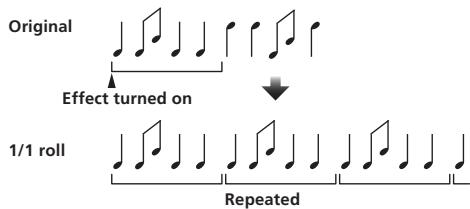
text_image
Original Effect turned on 1/1 roll Repeated| BEAT ◀, ► buttons (parameter 1) | Use these to set an effect time of 1/16 - 16/1 with respect to the time of one beat of the BPM. |
| TIME control (parameter 2) | Use this to set the effect time. 10 to 4000 (ms) |
| LEVEL/DEPTH control (parameter 3) | Use this to set the balance between the original sound and ROLL. |
REV ROLL ^1 ^2
The sound being input at the point when the [ON/OFF] button is pressed is recorded, and the recorded sound is reversed then output repeatedly according to the beat fraction set with the [BEAT ◀, ▶] buttons.
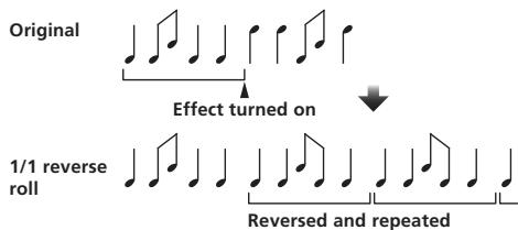
text_image
Original Effect turned on 1/1 reverse roll Reversed and repeated| BEAT ◀, ► buttons (parameter 1) | Use these to set an effect time of 1/16 - 16/1 with respect to the time of one beat of the BPM. |
| TIME control (parameter 2) | Use this to set the effect time. 10 to 4000 (ms) |
| LEVEL/DEPTH control (parameter 3) | Use this to set the balance between the original sound and ROLL. |
SND/RTN ^1
Connect an external effector, etc., here.
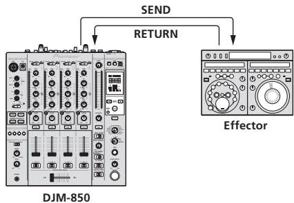
flowchart
graph TD
    A["DJM-850"] -->|SEND| B["Effector"]
    A -->|RETURN| B
| BEAT ◀, ► buttons (parameter 1) | — |
| TIME control (parameter 2) | — |
| LEVEL/DEPTH control (parameter 3) | This adjusts the sound level input to the [RETURN] terminal. |
If the sound of the channel you want to monitor is not output from the [MASTER] channel when [CF.A], [CF.B] or [MASTER] is selected with the [1, 2, 3, 4, MIC, CF.A, CF.B, MASTER] selector switch, the effect sound cannot be monitored even by pressing the [CUE] button for [BEAT EFFECTS].
2 If the effect is off, the effect sound cannot be monitored even by pressing the [CUE] button for [BEAT EFFECTS].
List of MIDI Messages
- "CC" is the abbreviation of "control change". A control change is a type of MIDI signal used to transmit various types of control information, such as timbre, volume, etc. On this unit, values from 0 to 127 are output as CC mainly when controls and faders are operated. CC are also output when certain buttons are operated.
- “Note” is a MIDI term used when pressing or releasing notes on a piano or other keyboard.
When turning one button on switches another button from on to off, MIDI on and off messages are sent from the two buttons. When there is no button that switches off, only the MIDI on message is sent from the button that was pressed.
2 When switched from one position to another position, the MIDI ON and OFF signals are sent respectively from both positions.
- When the [START/STOP] button is pressed for over 1 second, MIDI messages corresponding to the positions of the buttons, faders and controls are sent in a bundle (Snapshot).
| Category | SW Name | SW Type | MIDI assignment | Trigger/Toggle | Transmitted data | |
| CH1 | TRIM | Control | CC 001 | — | 0-127 | |
| HI | Control | CC 002 | — | 0-127 | ||
| MID | Control | CC 003 | — | 0-127 | ||
| LOW | Control | CC 004 | — | 0-127 | ||
| BEAT | Button | CC 101 | Trigger/Toggle | OFF=0, ON=127 | ||
| COLOR | Control | CC 005 | — | 0-127 | ||
| CUE | Button | CC 070 | Trigger/Toggle | OFF=0, ON=127 | ||
| Channel fader | Control | CC 017 | — | 0-127 | ||
| CROSS FADER ASSIGN | Switch | CC 065 | — | 0, 64, 127 | ||
| CH2 | TRIM | Control | CC 006 | — | 0-127 | |
| HI | Control | CC 007 | — | 0-127 | ||
| MID | Control | CC 008 | — | 0-127 | ||
| LOW | Control | CC 009 | — | 0-127 | ||
| BEAT | Button | CC 102 | Trigger/Toggle | OFF=0, ON=127 | ||
| COLOR | Control | CC 010 | — | 0-127 | ||
| CUE | Button | CC 071 | Trigger/Toggle | OFF=0, ON=127 | ||
| Channel fader | Control | CC 018 | — | 0-127 | ||
| CROSS FADER ASSIGN | Switch | CC 066 | — | 0, 64, 127 | ||
| CH3 | TRIM | Control | CC 012 | — | 0-127 | |
| HI | Control | CC 014 | — | 0-127 | ||
| MID | Control | CC 015 | — | 0-127 | ||
| LOW | Control | CC 021 | — | 0-127 | ||
| BEAT | Button | CC 103 | Trigger/Toggle | OFF=0, ON=127 | ||
| COLOR | Control | CC 022 | — | 0-127 | ||
| CUE | Button | CC 072 | Trigger/Toggle | OFF=0, ON=127 | ||
| Channel fader | Control | CC 019 | — | 0-127 | ||
| CROSS FADER ASSIGN | Switch | CC 067 | — | 0, 64, 127 | ||
| CH4 | TRIM | Control | CC 080 | — | 0-127 | |
| HI | Control | CC 081 | — | 0-127 | ||
| MID | Control | CC 092 | — | 0-127 | ||
| LOW | Control | CC 082 | — | 0-127 | ||
| BEAT | Button | CC 104 | Trigger/Toggle | OFF=0, ON=127 | ||
| COLOR | Control | CC 083 | — | 0-127 | ||
| CUE | Button | CC 073 | Trigger/Toggle | OFF=0, ON=127 | ||
| Channel fader | Control | CC 020 | — | 0-127 | ||
| CROSS FADER ASSIGN | Switch | CC 068 | — | 0, 64, 127 | ||
| Crossfader | Crossfader | Control | CC 011 | — | 0-127 | |
| Fader curve | CH FADER (√, √, √) | Switch | CC 094 | — | 0, 64, 127 | |
| CROSS FADER (×, ××) | Switch | CC 095 | — | 0, 64, 127 | ||
| Master | MASTER LEVEL | Control | CC 024 | — | 0-127 | |
| BALANCE | Control | CC 023 | — | 0-127 | ||
| CUE | Button | CC 074 | Trigger/Toggle | OFF=0, ON=127 | ||
| EQ CURVE (ISOLATOR, EQ) | Switch | CC 033 | — | 0, 127 | ||
| BOOTH MONITOR | BOOTH MONITOR | Control | CC 025 | — | 0-127 | |
| BEAT EFFECTS | ◀ | Button | CC 076 | Trigger only | OFF=0, ON=127 | |
| ▶ | Button | CC 077 | Trigger only | OFF=0, ON=127 | ||
| AUTO/TAP | Button | CC 069 | Trigger/Toggle | OFF=0, ON=127 | ||
| TAP | Button | CC 078 | Trigger only | OFF=0, ON=127 | ||
| CUE | Button | CC 075 | Trigger/Toggle | OFF=0, ON=127 | ||
| Category | SW Name | SW Type | MIDI assignment | Trigger/Toggle | Transmitted data | |
| BEAT EFFECTS | EFFECT SELECT | DELAY | Switch | CC 042 | 2 | OFF=0, ON=127 |
| ECHO | Switch | CC 055 | 2 | OFF=0, ON=127 | ||
| UP ECHO | Switch | CC 061 | 2 | OFF=0, ON=127 | ||
| SPIRAL | Switch | CC 043 | 2 | OFF=0, ON=127 | ||
| REVERB | Switch | CC 054 | 2 | OFF=0, ON=127 | ||
| TRANS | Switch | CC 053 | 2 | OFF=0, ON=127 | ||
| FILTER | Switch | CC 059 | 2 | OFF=0, ON=127 | ||
| FLANGER | Switch | CC 050 | 2 | OFF=0, ON=127 | ||
| PHASER | Switch | CC 057 | 2 | OFF=0, ON=127 | ||
| ROBOT | Switch | CC 051 | 2 | OFF=0, ON=127 | ||
| SLIP ROLL | Switch | CC 058 | 2 | OFF=0, ON=127 | ||
| ROLL | Switch | CC 046 | 2 | OFF=0, ON=127 | ||
| REV ROLL | Switch | CC 047 | 2 | OFF=0, ON=127 | ||
| SND/RTN | Switch | CC 062 | 2 | OFF=0, ON=127 | ||
| CH SELECT | CH1 | Switch | CC 034 | 2 | OFF=0, ON=127 | |
| CH2 | Switch | CC 035 | 2 | OFF=0, ON=127 | ||
| CH3 | Switch | CC 036 | 2 | OFF=0, ON=127 | ||
| CH4 | Switch | CC 037 | 2 | OFF=0, ON=127 | ||
| MIC | Switch | CC 038 | 2 | OFF=0, ON=127 | ||
| CF.A | Switch | CC 039 | 2 | OFF=0, ON=127 | ||
| CF.B | Switch | CC 040 | 2 | OFF=0, ON=127 | ||
| MASTER | Switch | CC 041 | 2 | OFF=0, ON=127 | ||
| TIME | Switch | CC 013 | — | — | ||
| Switch | CC 045 | — | TIME value (When FLANGER, PHASER or FILTER is selected, the value is halved. When a negative value is selected, it is set to a positive value.) | |||
| LEVEL/DEPTH | Switch | CC 091 | — | 0-127 | ||
| ON/OFF• When an effect other than [SND/RTN] is selected at BEAT EFFECT | Button | CC 114 | — | OFF=0, ON=127 | ||
| ON/OFF• When [SND/RTN] is selected at BEAT EFFECT | Button | CC 064 | — | OFF=0, ON=127 | ||
| MIC | HI | Control | CC 030 | — | 0-127 | |
| LOW | Control | CC 031 | — | 0-127 | ||
| SOUND COLOR FX | NOISE | Button | CC 085 | Trigger/Toggle ^1 | OFF=0, ON=127 | |
| GATE | Button | CC 105 | Trigger/Toggle ^1 | OFF=0, ON=127 | ||
| CRUSH | Button | CC 086 | Trigger/Toggle ^1 | OFF=0, ON=127 | ||
| FILTER | Button | CC 087 | Trigger/Toggle ^1 | OFF=0, ON=127 | ||
| Fader Start | FADER START 1 | Button | CC 088 | Trigger/Toggle | OFF=0, ON=127 | |
| FADER START 2 | Button | CC 089 | Trigger/Toggle | OFF=0, ON=127 | ||
| FADER START 3 | Button | CC 090 | Trigger/Toggle | OFF=0, ON=127 | ||
| FADER START 4 | Button | CC 093 | Trigger/Toggle | OFF=0, ON=127 | ||
| HEADPHONES | MIXING | Control | CC 027 | — | 0-127 | |
| LEVEL | Control | CC 026 | — | 0-127 | ||
| Timing Clock | — | Timing Clock | — | — | ||
| Fader Start | FADER START 1 | Note 102 | — | BACK CUE = 0, PLAY = 127 | ||
| FADER START 2 | Note 103 | — | BACK CUE = 0, PLAY = 127 | |||
| FADER START 3 | Note 104 | — | BACK CUE = 0, PLAY = 127 | |||
| FADER START 4 | Note 105 | — | BACK CUE = 0, PLAY = 127 | |||
| MIDI | START | Button | START | — | — | |
| STOP | Button | STOP | — | — | ||
The MIDI Snapshot sends all MIDI messages other than MIDI start and MIDI stop.
Changing the settings
1 Press the [MIDI] [SETUP (WAKE UP)] button for at least 1 second.
The [USER SETUP] screen is displayed.
- To display the [CLUB SETUP] screen, first turn the unit's power off, then press the [POWER] button while pressing the [MIDI] [SETUP (WAKE UP)] button.
2 Press the [BEAT ◀, ▶] button.
Select the setting item.
3 Press the [TAP] button.
The screen switches to the setting item's setting value change screen.
4 Press the [BEAT ◀, ▶] button.
Change the setting value.
5 Press the [TAP] button.
Enter the setting value.
The previous screen reappears.
- To return to the previous screen without changing the settings, press the [AUTO/TAP] button.
6 Press the [SETUP (WAKE UP)] button.
Close the [USER SETUP] screen.
- To close the [CLUB SETUP] screen, press the [POWER] button to turn this unit's power off.
About the auto standby function
When [Auto Standby] is set to [ON], the standby mode is set automatically if 4 hours pass with all of the conditions shown below met.
— That none of this unit's buttons or controls are operated.
— That no audio signals of -10 dB or greater are input to this unit's input terminals.
- When the [SETUP (WAKE UP)] button is pressed, the standby mode is canceled.
- This unit is shipped with the auto standby function turned on. If you do not want to use the auto standby function, set [Auto Standby] to [OFF].
About the talk over function
The talk over function has the two modes described below.
— [ADV] (advanced talk over): The mid-range only of the sound of channels other than the [MIC] channel is attenuated according to the [Talk Over LEVEL] setting value and output.
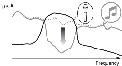
text_image
dB Frequency— [NOR] (normal talk over): The sound of channels other than the [MIC] channel is attenuated according to the [Talk Over LEVEL] setting value and output.
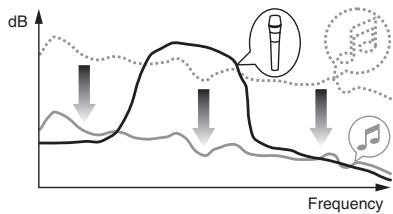
line
| Frequency | dB (Solid Line) | dB (Dotted Line) | | --------- | --------------- | ---------------- | | Low | ~0 | ~0 | | Medium | Peak | ~0.8 | | High | Decreasing | Decreasing |Setting preferences
*: Setting upon purchase
| Mode | Options settings | Screen display | Setting value | Descriptions |
| USER SETUP | Fader Start | F.S. | ON*, OFF | Turns the fader start function on and off for all DJ players connected to the [CONTROL] terminals. |
| MIDI CH | MIDI CH | 1* to 16 | Sets the MIDI channel. | |
| MIDI Button Type | MIDI BT | TGL*, TRG | Selects the MIDI signal transmission mode, [TGL (TOGGLE)] or [TRG (TRIGGER)]. | |
| Talk Over Mode | TLK MOD | ADV*, NOR | Selects the talk over function's mode, [ADV(ADVANCED)] or [NOR(NORMAL)]. | |
| Talk Over LEVEL | TLK LVL | -6 dB, -12 dB, -18 dB*, -24 dB | Sets the talk over function's sound attenuation level. | |
| CLUB SETUP | Digital Master Out Level | DOUT LV | -19 dB*, -15 dB, -10 dB, -5 dB | Sets the maximum level of the sound output from the [DIGITAL MASTER OUT] terminals.1 |
| Digital Master Out Sampling Rate | DOUT FS | 48 kHz, 96 kHz* | Sets the digital signal's sampling rate. | |
| MASTER ATT. | MST ATT | -6 dB, -3 dB, 0 dB* | Sets the attenuation level of the sound output from the [MASTER1] and [MASTER2] terminals. | |
| Auto Standby | AUTOSTB | ON*, OFF | Turns the auto standby function on and off. | |
| Mic Output To Booth Monitor | MIC BTH | ON*, OFF | Sets whether or not to output the microphone's audio signals from [BOOTH] terminals. | |
| PC UTILITY | PC UTLY | ON*, OFF | Sets whether or not to launch the computer's setting utility software automatically when a USB cable is connected. | |
| Factory Reset | INITIAL | YES, NO* | Restores all the settings to their factory defaults. |
1 Note that the output sound may be distorted even if the master level indicator does not light up to the very top.
Additional information
Troubleshooting
- Incorrect operation is often mistaken for trouble or malfunction. If you think that there is something wrong with this component, check the points below. Sometimes the trouble may lie in another component. Inspect the other components and electrical appliances being used. If the trouble cannot be rectified after checking the items below, ask your nearest Pioneer authorized service center or your dealer to carry out repair work.
- The player may not operate properly due to static electricity or other external influences. In such cases, normal operation may be restored by unplugging the power cord then plugging it back in.
| Problem | Check | Remedy |
| The power is not turned on. | Is the power cord properly connected? | Plug in the power cord to an AC outlet. |
| No sound or small sound. | Is the [CD/LINE, PHONO, LINE, USB */*] selector switch set to the proper position? | Switch the [CD/LINE, PHONO, LINE, USB */*] selector switch to switch the channel's input source. (page 14) |
| Are the connection cables properly connected? | Connect the connection cables properly. (page 7) | |
| Are the terminals and plugs dirty? | Clean the terminals and plugs before making connections. | |
| Is [MASTER ATT.] set to [-6 dB], etc.? | At the [CLUB SETUP] screen, switch [MASTER ATT]. (page 23) | |
| Digital sound cannot be output. | Is the digital audio output's sampling frequency (fs) suited for the specifications of the connected device? | On the [CLUB SETUP] screen, set [Digital Master Out Sampling Rate] according to the specifications of the connected equipment. (page 23) |
| Distorted sound. | Is the sound level output from the [MASTER] channel appropriately set? | Adjust the [MASTER LEVEL] control so that the master channel level indicator lights at around [0 dB] at the peak level. (Page 14) |
| Set [MASTER ATT.] to [-3 dB] or [-6 dB]. (page 23) | ||
| Is the level of audio input to each channel properly set? | Adjust the [TRIM] control so that the channel level indicator lights at about [0 dB] at the peak level. (Page 14) | |
| Can't crossfade. | Are the CROSS FADER ASSIGN (A, THRU, B) selector switches properly set? | Set the [CROSS FADER ASSIGN (A, THRU, B)] selector switches for the different channels properly. (Page 14) |
| Can't fader start a DJ player. | Is [FADER START] set to [OFF]? | At the [USER SETUP] screen, set [FADER START] to [ON]. (page 23) |
| Set the [FADER START] button on the control panel to [ON]. (Page 14) | ||
| Is the DJ player properly connected to the [CONTROL] terminal? | Properly connect the [CONTROL] terminal and DJ player using a control cable. (page 7) | |
| Are the audio cables properly connected? | Connect this unit's audio input terminals and the DJ player's audio output terminals by audio cable. (page 7) | |
| [BEAT EFFECTS] does not work. | Is the [1, 2, 3, 4, MIC, CF.A, CF.B, MASTER] selector switch properly set? | Turn the [1, 2, 3, 4, MIC, CF.A, CF.B, MASTER] selector switch to select the channel to which you want to apply the effect. (Page 16) |
| [SOUND COLOR FX] does not work. | Is the [COLOR] control set to an appropriate position? | Turn the [COLOR] control clockwise or counterclockwise. (page 16) |
| [BEAT COLOR FX] does not work. | Is the [SOUND COLOR FX] [BEAT] button set to [ON]? | Set the [SOUND COLOR FX] [BEAT] button to [ON]. (page 16) |
| Can't use an external effector. | Is the [ON/OFF] button for [BEAT EFFECTS] set to [ON]? | Press the [ON/OFF] button for [BEAT EFFECTS] to set [SND/RTN] to [ON]. (page 16) |
| Is the external effector properly connected to the [SEND] or [RETURN] terminal? | Connect the external effector to the [SEND] and [RETURN] terminals. (page 7) | |
| Distorted sound from an external effector. | Is the external effector's audio output level set to an appropriate level? | Adjust the external effector's audio output level. |
| Tempo (BPM) cannot be measured or measurement value of tempo (BPM) is implausible. | Is the audio input level too high or too low? | Adjust the [TRIM] control so that the channel level indicator lights at about [0 dB] at the peak level. (Page 14) |
| For some tracks, it may not be possible to measure the tempo (BPM). Use the [TAP] button to input the tempo manually. (page 16) | ||
| Measured tempo (BPM) differs from tempo indicated on CD. | — | The values may differ slightly due to the different ways in which the BPM is measured. There is no need to make any corrections. |
| MIDI sequencer does not synchronize. | Is the MIDI sequencer's sync mode set to Slave? | Set the MIDI sequencer's sync mode to Slave. |
| Does the MIDI sequencer you are using support MIDI timing clocks? | MIDI sequencers not supporting MIDI timing clocks cannot be synchronized. | |
| MIDI control does not work. | Is the MIDI channel turned on? | Press the [ON/OFF] button for [MIDI]. (Operating DJ software using the MIDI function on page 17) |
| Are the MIDI settings properly set? | To operate DJ software with this unit, this unit's MIDI messages must be assigned to the DJ software you are using. For instructions on assigning messages, see your DJ software's operating instructions. | |
| This unit is not recognized after it has been connected to a computer. | Is the driver software properly installed on your computer? | Install the driver software. If it is already installed, reinstall it. (page 8) |
| Sound of a computer cannot be output from this unit. | Are this unit and computer properly connected? | Connect this unit and the computer directly using the included USB cable. (page 8) |
| Are the audio output device settings properly set? | Select this unit with the audio output device settings. For instructions on making settings for your application, see your application's operating instructions. | |
| Is the [CD/LINE, PHONO, LINE, USB */*] selector switch set to the proper position? | Set the [CD/LINE, PHONO, LINE, USB */*] selector switch to the [USB */*] position. (Page 14) | |
| Effect sound cannot be monitored even when the [CUE] button for [BEAT EFFECTS] is pressed. | — | The circuit generating the [ECHO], [UP ECHO], [SPIRAL], [REVERB], [ROLL], [SLIP ROLL] and [REV ROLL] echo sounds is positioned after the effect circuit, so the effect sound cannot be monitored. This is not a malfunction. |
| Sound is distorted when an analog player is connected to this unit's [PHONO] terminals.Or, lighting of the channel level indicator does not change even when the [TRIM] control is turned. | Have you connected an analog player with a built-in phono equalizer? | For analog players with built-in phono equalizers, connect the player to the [CD/LINE] or [LINE] terminals. (page 7) |
| If the analog player with built-in phono equalizer has a PHONO/LINE selector switch, switch it to PHONO. | ||
| Is an audio interface for computers connected between the analog player and this unit? | If the audio interface for computers has a line level output, connect it to the [CD/LINE] or [LINE] terminal. (page 7) | |
| If the analog player has a PHONO/LINE selector switch, switch it to PHONO. |
Block Diagram
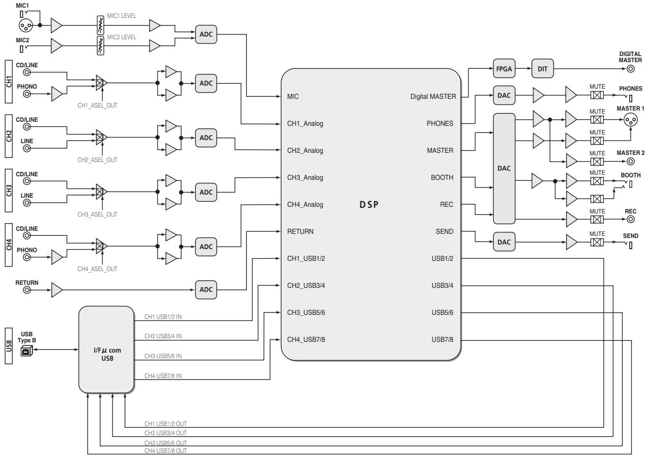
flowchart
graph LR
    subgraph_Channel_1["CH1"]
        A1["CM1"] --> B1["MC1 LEVEL"]
        A2["CM2"] --> B2["MC2 LEVEL"]
        B1 --> C1["ADC"]
        B2 --> C2["ADC"]
        C1 --> D1["MIC"]
        C2 --> D2["MIC"]
    end

    subgraph_Channel_2["CH2"]
        A3["CD/LINE"] --> B3["CH1_ASEL_OUT"]
        A4["CD/LINE"] --> B4["CH2_ASEL_OUT"]
        B3 --> C3["ADC"]
        B4 --> C4["ADC"]
        C3 --> D3["MIC"]
        C4 --> D4["MIC"]

    end

    subgraph_Channel_3["CH3"]
        A5["CD/LINE"] --> B5["CH3_ASEL_OUT"]
        A6["CD/LINE"] --> B6["CH4_ASEL_OUT"]
        B5 --> C5["ADC"]
        B6 --> C6["ADC"]
        C5 --> D5["MIC"]
        C6 --> D6["MIC"]

    end

    subgraph_Channel_4["CH4"]
        A7["CD/LINE"] --> B7["CH4_ASEL_OUT"]
        A8["CD/LINE"] --> B8["CH4_ASEL_OUT"]
        B7 --> C7["ADC"]
        B8 --> C8["ADC"]
        C7 --> D7["MIC"]
        C8 --> D8["MIC"]

    end

    subgraph_Channel_5["RETURN"]
        A9["CH1_USB1/2"] --> B9["CH2_USB3/4"]
        A10["CH3_USB5/6"] --> B10["CH4_USB7/8"]

        C9["CH1 USB1/2 IN"] --> D10["USB1/2"]

        C10["CH2 USB3/4 IN"] --> D20["USB3/4"]

        C11["CH3 USB5/6 IN"] --> D30["USB5/6"]

        C12["CH4 USB7/8 IN"] --> D40["USB7/8"]

    end

    subgraph_Channel_6["DSP"]
        D5["DSP"] --> E1["FPGA"]
        D6["DSP"] --> E2["DIT"]
        E1 --> F1["DAC"]
        E2 --> F2["DAC"]
        F1 --> G1["MUTE"]
        F2 --> G2["MUTE"]
        F2 --> G3["MUTE"]
        F2 --> G4["MUTE"]
        F2 --> G5["MUTE"]
        F2 --> G6["MUTE"]
        F2 --> G7["MUTE"]
        F2 --> G8["MUTE"]
        F2 --> G9["MUTE"]
        F2 --> G10["MUTE"]
        F2 --> G11["MUTE"]
        F2 --> G12["MUTE"]
        F2 --> G13["MUTE"]
        F2 --> G14["MUTE"]
        F2 --> G15["MUTE"]
        F2 --> G16["MUTE"]
        F2 --> G17["MUTE"]
        F2 --> G18["MUTE"]
        F2 --> G19["MUTE"]
    end

    subgraph Digital MASTER
        D7["DSP"] --> E3["DAC"]
        E3 --> F3["FPGA"]
        E3 --> F4["DIT"]
        F3 --> G4["DAC"]
        F4 --> G5["DAC"]
        G4 --> G6["DAC"]
        G5 --> G7["DAC"]
    end

    subgraph DAC
        E7["DAC"] --> F7["DAC"]
        F7 --> G8["DAC"]
        G8 --> G9["DAC"]
    end

    subgraph I/Fμ com USB
        I_FA["I/Fμ com USB"] --> J["FI/Fμ com USB"]
    end

    style Channel_5 fill:#f9f,stroke:#333
    style Channel_6 fill:#ccf,stroke:#333
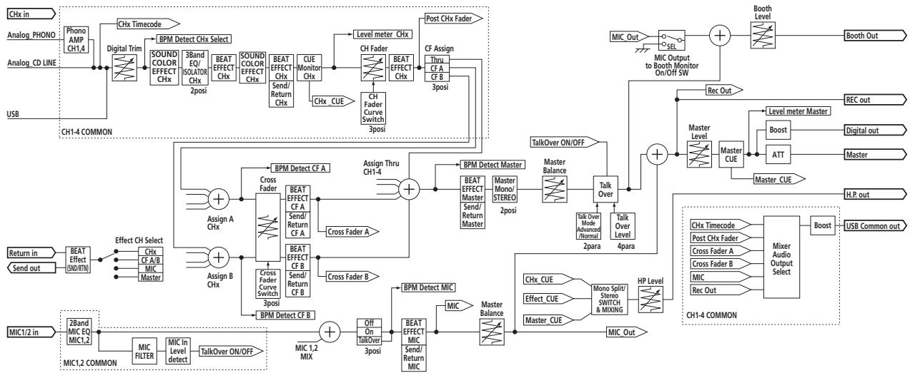
flowchart
graph TD
    A["Chx in"] --> B["Analog. PHONO"]
    A --> C["Analog. CD LINE"]
    A --> D["USB"]
    B --> E["Chx Timecode"]
    C --> F["Chx Timecode Select"]
    D --> G["CHx CUE"]
    E --> H["Digital Trim"]
    F --> I["SOUND COLOR EFFECT CHx"]
    G --> J["SOUND COLOR EFFECT CHx"]
    H --> K["BPM Detect CHx Select"]
    I --> L["SOUND COLOR EFFECT CHx 2posi"]
    J --> M["BEAT EFFECT CHx"]
    K --> N["CUE Monitor CHx"]
    L --> O["BEAT EFFECT CHx"]
    M --> P["CUE Monitor CHx"]
    N --> Q["BEAT EFFECT CHx"]
    O --> R["CHx CUE"]
    P --> S["CHx CUE"]
    Q --> T["CHFader Curve Switch 3posi"]
    R --> U["BEAT EFFECT CHx"]
    S --> V["BEAT EFFECT CHx 3posi"]
    T --> W["Post CHx Fader"]
    U --> X["CF Assign"]
    V --> Y["CF Assign"]
    W --> Z["CF Assign"]
    X --> AA["CF Assign"]
    Y --> AB["CF Assign"]
    Z --> AC["CHFader Curve Switch 3posi"]
    AA --> AD["CHFader Curve Switch 3posi"]
    AB --> AE["CHFader Curve Switch 3posi"]
    AC --> AF["CHFader Curve Switch 3posi"]
    AD --> AG["CHFader Curve Switch 3posi"]
    AE --> AH["CHFader Curve Switch 3posi"]
    AF --> AI["CHFader Curve Switch 3posi"]
    AG --> AJ["CHFader Curve Switch 3posi"]
    AH --> AK["CHFader Curve Switch 3posi"]
    AI --> AL["CHFader Curve Switch 3posi"]
    AJ --> AM["CHFader Curve Switch 3posi"]
    AK --> AN["CHFader Curve Switch 3posi"]
    AL --> AO["CHFader Curve Switch 3posi"]
    AM --> AP["CHFader Curve Switch 3posi"]
    AN --> AQ["CHFader Curve Switch 3posi"]
    AO --> AR["CHFader Curve Switch 3posi"]
    AP --> AS["CHFader Curve Switch 3posi"]
    AQ --> AT["CHFader Curve Switch 3posi"]
    AR --> AU["CHFader Curve Switch 3posi"]
    AS --> AV["CHFader Curve Switch 3posi"]
    AT --> AW["CHFader Curve Switch 3posi"]
    AU --> AX["CHFader Curve Switch 3posi"]
    AV --> AY["CHFader Curve Switch 3posi"]
    AW --> AZ["CHFader Curve Switch 3posi"]
    AX --> BA["CHFader Curve Switch 3posi"]
    AY --> BB["CHFader Curve Switch 3posi"]
    AZ --> BC["CHFader Curve Switch 3posi"]
    BA --> BD["CHFader Curve Switch 3posi"]
    BB --> BE["CHFader Curve Switch 3posi"]
    BC --> BF["CHFader Curve Switch 3posi"]
    BE --> BG["CHFader Curve Switch 3posi"]
    BF --> BH["CHFader Curve Switch 3posi"]
    BG --> BI["CHFader Curve Switch 3posi"]
    BH --> BJ["CHFader Curve Switch 3posi"]
    BI --> BK["CHFader Curve Switch 3posi"]
    BJ --> BL["CHFader Curve Switch 3posi"]
    BK --> BM["CHFader Curve Switch 3posi"]
    BL --> BN["CHFader Curve Switch 3posi"]
    BM --> BO["CHFader Curve Switch 3posi"]
    BN --> BP["MIC1/2 COMMON"]
    BO --> BP1["2Band MIC EQ MIC1,2 MIC FILTER"]
    BP1 --> BP2["MIC In Level detect"]
    BP2 --> BP3["TalkOver ON/OFF"]
    BP3 --> BP4["MIC1,2 MIX"]
    BP4 --> BP5["Off On TalkOver 3posi"]
    BP5 --> BP6["BPM Detect MIC"]
    BP6 --> BP7["BPM Detect MIC"]
    BP7 --> BP8["BPM Detect MIC"]
    BP8 --> BP9["BPM Detect MIC"]
    BP9 --> BP10["BPM Detect MIC"]
    BP10 --> BP11["BPM Detect MIC"]
    BP11 --> BP12["BPM Detect MIC"]
    BP12 --> BP13["BPM Detect MIC"]
    BP13 --> BP14["BPM Detect MIC"]
    BP14 --> BP15["BPM Detect MIC"]
    BP15 --> BP16["BPM Detect MIC"]
    BP16 --> BP17["BPM Detect MIC"]
    BP17 --> BP18["BPM Detect MIC"]
    BP18 --> BP19["BPM Detect MIC"]
    BP19 --> BP20["BPM Detect MIC"]

flowchart
graph TD
    A["Effect CH Select"] --> B["Cable Check"]
    B --> C["No Cable"]
    C --> D["Effect SW"]
    D --> E["Effect CUE"]
    F["RETURN"] --> G["Cable Exist"]
    G --> C
    H["CHx"] --> I["Cable Check"]
    J["CF A/B"] --> K["Cable Check"]
    L["MIC"] --> M["Cable Check"]
    N["Master"] --> O["Cable Check"]
    P["SEND Out"] --> Q["Effect CH Select Effect Out"]
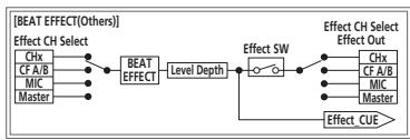
flowchart
graph LR
    A["BEAT EFFECT(Others)"] --> B["Effect CH Select"]
    B --> C["CHx"]
    B --> D["CF A/B"]
    B --> E["MIC"]
    B --> F["Master"]
    C --> G["BEAT EFFECT"]
    D --> G
    E --> G
    F --> G
    G --> H["Level Depth"]
    H --> I["Effect SW"]
    I --> J["Effect CUE"]
    J --> K["Effect CH Select Effect Out"]
    K --> L["Effect SW"]
    L --> M["Effect CUE"]
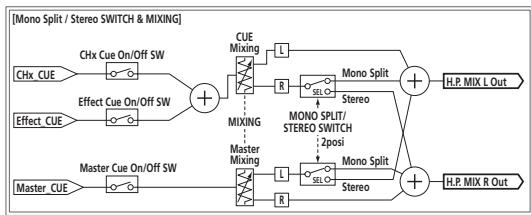
flowchart
graph TD
    A["Chx_CUE"] --> B["Effect Cue On/Off SW"]
    B --> C["Master Cue On/Off SW"]
    D["Chx_Cue On/Off SW"] --> E["Effect Cue On/Off SW"]
    E --> F["Master Cue On/Off SW"]
    G["Cue Mixing"] --> H["R"]
    I["Mixing"] --> J["L"]
    K["Master Mixing"] --> L["R"]
    M["Cue Mixing"] --> N["L"]
    O["Mixing"] --> P["R"]
    Q["Mono Split"] --> R["Stereo"]
    S["Mono Split/Stereo SWITCH"] --> T["Stereo"]
    U["H.P. MIX L Out"] --> V["+"]
    W["H.P. MIX R Out"] --> X["+"]
    Y["Monosplitual Mix"] --> Z["+"]
    AA["Monosplitual Mix"] --> AB["+"]
    AC["Monosplitual Mix"] --> AD["+"]
About trademarks and registered trademarks
- Pioneer and rekordbox are trademarks or registered trademarks of the PIONEER CORPORATION.
- Microsoft ^® , Windows ^® 7, Windows Vista ^® , Windows ^® XP, and Windows ^® are either registered trademarks or trademarks of Microsoft Corporation in the United States and/or other countries.
- Apple, Macintosh and Mac OS are trademarks of Apple Inc., registered in the U.S. and other countries.
• ASIO is a trademark of Steinberg Media Technologies GmbH.
Specifications
General
Power requirements ......AC 220 V to 240 V, 50 Hz/60 Hz
Power consumption.... 32 W
Power consumption (standby) 0.45 W
Main unit weight 7.7 kg
Max. external dimensions ....320 mm (width) x 108 mm (height) x 381 mm (depth)
Tolerable operating temperature ....+5 °C to +35 °C
Tolerable operating humidity .... 5 % to 85 % (no condensation)
Audio Section
Sampling rate 96 kHz
MASTER D/A converter 32 bits
Other A/D and D/A converters 24 bits
Frequency characteristic CD/LINE 20 Hz to 20 kHz
S/N ratio (rated output, A-WEIGHTED)
PHONO....92 dB
CD/LINE....106 dB
MIC1, MIC2 84 dB
Total harmonic distortion (20 kHzBW) CD/LINE — MASTER1....0.004 %
Standard input level / Input impedance
PHONO....-52 dBu/47 kΩ
CD/LINE -12 dBu/47 kΩ
MIC1 -52 dBu/8.5 kΩ
MIC2 -52 dBu/49 kΩ
RETURN....-12 dBu/49 kΩ
Standard output level / Load impedance / Output impedance MASTER1....+6 dBu/10 kΩ/360 Ω or lower MASTER2....+2 dBu/10 kΩ/390 Ω or lower REC OUT....-8 dBu/10 kΩ/22 Ω or lower BOOTH....+6 dBu/10 kΩ/360 Ω or lower SEND....-12 dBu/10 kΩ/1 kΩ or lower PHONES....+8.5 dBu/32 Ω/10 Ω or lower
Rated output level / Load impedance MASTER1....+24 dBu/10 kΩ MASTER2....+20 dBu/10 kΩ
Crosstalk LINE 82 dB
Channel equalizer characteristic HI ....-26 dB to +6 dB (13 kHz) MID ....-26 dB to +6 dB (1 kHz) LOW ....-26 dB to +6 dB (70 Hz)
Microphone equalizer characteristic HI ....-12 dB to +12 dB (10 kHz) LOW ....-12 dB to +12 dB (100 Hz)
Input / Output terminals
PHONO input terminal RCA pin jack....2 sets
CD/LINE input terminal RCA pin jacks......4 sets
LINE input terminal RCA pin jack....2 sets
MIC1 input terminal XLR connector/phone jack (∅ 6.3 mm) ....1 set
MIC2 input terminal Phone jack (∅ 6.3 mm)....1 set
RETURN Input terminals Phone jack (∅ 6.3 mm)....1 set
MASTER output terminal XLR connector....1 set RCA pin jacks....1 set
BOOTH output terminal Phone jack (∅ 6.3 mm)....1 set
REC OUT output terminal RCA pin jacks....1 set
SEND output terminal Phone jack (∅ 6.3 mm)....1 set
DIGITAL MASTER OUT coaxial output terminal RCA pin jacks....1 set
MIDI OUT terminal 5P DIN ....1 set
PHONES output terminal Stereo phone jack (∅ 6.3 mm) ....1 set
USB terminal B type....1 set
CONTROL terminal Mini phone jack (∅ 3.5 mm)....4 sets
— The specifications and design of this product are subject to change without notice.
— Be sure to use the [MASTER1] terminals only for a balanced output. Connection with an unbalanced input (such as RCA) using an XLR to RCA converter cable (or converter adapter), etc., may lower the sound quality and/or result in noise. For connection with an unbalanced input (such as RCA), use the [MASTER2] terminals.
• © 2012 PIONEER CORPORATION. All rights reserved.
line
| Fréquence | dB | | --------- | ------ | | Low | Low | | Peak | High | | High | Decreasing from peak to baseline |flowchart
Audio output selection flowchart for CH1-4 COMMON audio, covering analog/USB signal paths, crossover/flection tests, and channel selection logic.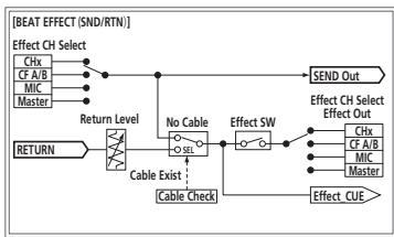
flowchart
graph TD
    A["Effect CH Select"] --> B["CHx"]
    A --> C["CF A/B"]
    A --> D["MIC"]
    A --> E["Master"]
    B --> F["Return Level"]
    C --> F
    D --> F
    E --> F
    F --> G["Cable Exist"]
    G --> H["No Cable"]
    H --> I["Effect SW"]
    I --> J["Effect CUE"]
    J --> K["Effect CH Select"]
    J --> L["Effect CUE"]
    K --> M["SEND Out"]
    L --> M
    H --> N["Cable Check"]
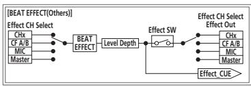
flowchart
graph LR
    A["CHx"] --> B["BEAT EFFECT"]
    C["CF A/B"] --> B
    D["MIC"] --> B
    E["Master"] --> B
    B --> F["Effect SW"]
    F --> G["Effect CUE"]
    G --> H["Effect CH Select Effect Out"]

flowchart
graph TD
    A["Chx_CUE"] --> B["Effect Cue On/Off SW"]
    C["Master_CUE"] --> D["Master Cue On/Off SW"]
    B --> E["MIXING"]
    D --> E
    E --> F["CUE Mixing"]
    E --> G["Master Mixing"]
    F --> H["L"]
    G --> I["R"]
    H --> J["Mono Split"]
    I --> K["Mono Split/STEREO SWITCH 2posi"]
    J --> L["H.P. MIX L Out"]
    K --> M["H.P. MIX R Out"]
    N["Effect_CUE"] --> O["Effect Cue On/Off SW"]
    P["Master_CUE"] --> Q["Master Cue On/Off SW"]
24 Bit/96 kHz STEREO 4-IN 4-OUT SOUNDKARTE
line
| Freqenz | dB (Solid Line) | dB (Dotted Line) | | ------- | --------------- | ---------------- | | 0 | ~0 | ~0 | | 500 | Peak | ~0.8 | | 1000 | Decreasing | ~0.6 | | 1500 | Decreasing | ~0.4 | | 2000 | Decreasing | ~0.3 | | 2500 | Decreasing | ~0.2 | | 3000 | Decreasing | ~0.1 | | 3500 | Decreasing | ~0.05 | | 4000 | Decreasing | ~0.02 | | 4500 | Decreasing | ~0.01 | | 5000 | Decreasing | ~0.005 | | 5500 | Decreasing | ~0.002 | | 6000 | Decreasing | ~0.001 | | 6500 | Decreasing | ~0.0005 | | 7000 | Decreasing | ~0.0002 | | 7500 | Decreasing | ~0.0001 | | 8000 | Decreasing | ~0.00005 | | 8500 | Decreasing | ~0.00002 | | 9000 | Decreasing | ~0.00001 | | 9500 | Decreasing | ~0.000005 | | 10000 | Decreasing | ~0.000002 |© 2012 PIONEER CORPORATION.
All rights reserved.
© 2012 PIONEER CORPORATION.