
A-509R - Audio Amplifier PIONEER - Free user manual and instructions
Find the device manual for free A-509R PIONEER in PDF.
| Product type | Integrated stereo audio amplifier |
| Brand | PIONEER |
| Model | A-509R |
| Dimensions (W x H x D) | 420 x 150 x 350 mm |
| Weight | 10 kg |
| Power supply | 220-240 V AC, 50/60 Hz |
| Output power | 100 W per channel into 8 ohms (RMS) |
| Audio inputs | Phono (MM), CD, Tuner, Aux, Tape 1/2 |
| Audio outputs | Speakers A/B, Pre-out, Headphone |
| Signal-to-noise ratio | 80 dB (line) |
| Frequency response | 20 Hz - 20 kHz ±0.5 dB |
| Controls | Volume, Balance, Bass, Treble, Loudness, Source selector |
| Protection | Short circuit, thermal, overload |
| Fuse | Fast or slow type (depending on version) |
| Power consumption | 400 W (max) |
| Operating temperature | 5°C to 35°C |
| Maintenance and cleaning | Soft dry cloth; do not use solvents |
| Safety | Do not expose to moisture; unplug before maintenance |
| Spare parts and repairability | Parts available from authorized dealers (fuses, transistors, etc.) |
Frequently Asked Questions - A-509R PIONEER
User questions about A-509R PIONEER
0 question about this device. Answer the ones you know or ask your own.
Ask a new question about this device
Download the instructions for your Audio Amplifier in PDF format for free! Find your manual A-509R - PIONEER and take your electronic device back in hand. On this page are published all the documents necessary for the use of your device. A-509R by PIONEER.
USER MANUAL A-509R PIONEER
THIS MANUAL IS APPLICABLE TO THE FOLLOWING MODEL(S) AND TYPE(S).
| Type | Model | Power Requirement | Remarks |
| A-509R | |||
| MY | ○ | AC220-230V |
CONTENTS
- SAFETY INFORMATION 2
- EXPLODED VIEWS AND PARTS LIST 3
-
BLOCK DIAGRAM AND SCHEMATIC DIAGRAM 6
4.PCB CONNECTION DIAGRAM 16
5.PCB PARTS LIST 21
6.ADJUSTMENT 24 -
GENERAL INFORMATION 25
7.1 IC 25
8.PANEL FACILITIES AND SPECIFICATIONS 26
1. SAFETY INFORMATION
This service manual is intended for qualified service technicians; it is not meant for the casual do-it-yourself. Qualified technicians have the necessary test equipment and tools, and have been trained to properly and safely repair complex products such as those covered by this manual.
Improperly performed repairs can adversely affect the safety and reliability of the product and may void the warranty. If you are not qualified to perform the repair of this product properly and safely, you should not risk trying to do so and refer the repair to a qualified service technician.
WARNING
This product contains lead in solder and certain electrical parts contain chemicals which are known to the state of California to cause cancer, birth defects or other reproductive harm.
Health & Safety Code Section 25249.6 - Proposition 65
NOTICE
(FOR CANADIAN MODEL ONLY)
Fuse symbols - (fast operating fuse) and/or - (slow operating fuse) on PCB indicate that replacement parts must be of identical designation.
REMARQUE
(POUR MODELE CANADIEN SEULEMENT)
The following check should be performed for the continued protection of the customer and service technician.
LEAKAGE CURRENT CHECK
Measure leakage current to a known earth ground (water pipe, conduit, etc.) by connecting a leakage current tester such as Simpson Model 229-2 or equivalent between the earth ground and all exposed metal parts of the appliance (input/output terminals, screwheads, metal overlays, control shaft, etc.). Plug the AC line cord of the appliance directly into a 120V AC 60Hz outlet and turn the AC power switch on. Any current measured must not exceed 0.5mA .
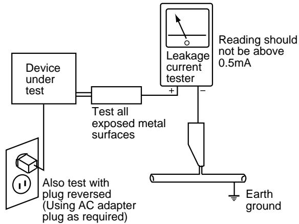
AC Leakage Test
ANY MEASUREMENTS NOT WITHIN THE LIMITS OUTLINED ABOVE ARE INDICATIVE OF A POTENTIAL SHOCK HAZARD AND MUST BE CORRECTED BEFORE RETURNING THE APPLIANCE TO THE CUSTOMER.
2. PRODUCT SAFETY NOTICE
Many electrical and mechanical parts in the appliance have special safety related characteristics. These are often not evident from visual inspection nor the protection afforded by them necessarily can be obtained by using replacement components rated for voltage, wattage, etc. Replacement parts which have these special safety characteristics are identified in this Service Manual.
Electrical components having such features are identified by marking with a on the schematics and on the parts list in this Service Manual.
The use of a substitute replacement component which does not have the same safety characteristics as the PIONEER recommended replacement one, shown in the parts list in this Service Manual, may create shock, fire, or other hazards.
Product Safety is continuously under review and new instructions are issued from time to time. For the latest information, always consult the current PIONEER Service Manual. A subscription to, or additional copies of, PIONEER Service Manual may be obtained at a nominal charge from PIONEER.
2. EXPLODED VIEWS AND PARTS LIST
NOTES: Parts marked by "NSP" are generally unavailable because they are not in our Master Spare Parts List.
- The mark found on some component parts indicates the importance of the safety factor of the part.
Therefore, when replacing, be sure to use parts of identical designation. - Screws adjacent to mark on the product are used for disassembly.
2.1 PACKING
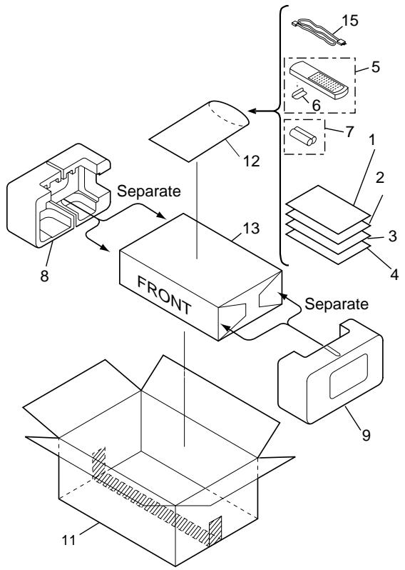
- PACKING PARTS LIST
| Mark | No. | Description | Part No. |
| 1 | Operating Instructions (English) | ARB7238 | |
| 2 | Operating Instructions (German) | ARC7326 | |
| 3 | Operating Instructions (French/Italian/Dutch/Swedish/Spanish/Portuguese) | ARC7327 | |
| NSP | 4 | Warranty Card | ARY7022 |
| 5 | Remote Control Unit (CU-A018) | AXD7187 | |
| 6 | Battery Cover | AZN2249 | |
| NSP | 7 | Dry Cell Battery (R6P,AA) | VEM-013 |
| 8 | Side Protector L | AHA7127 | |
| 9 | Side Protector R | AHA7128 | |
| 10 | ······· | ||
| 11 | Packing Case | AHD7898 | |
| NSP | 12 | Literature Bag | AHG-117 |
| 13 | Packing Sheet | AHG1016 | |
| 14 | ······· | ||
| Δ | 15 | Power Cord | ADG1154 |
2.2 EXTERIOR
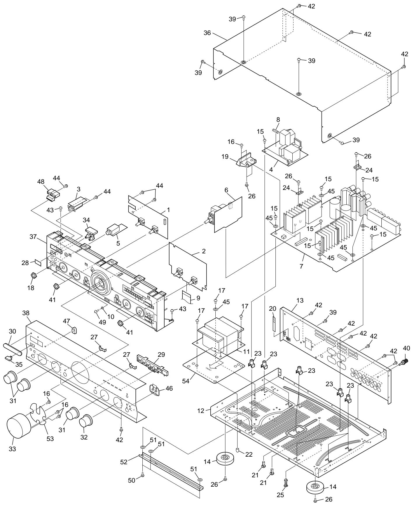
- EXTERIOR PARTS LIST
| Mark | No. | Description | Part No. |
| NSP | 1 | FRONT L Assy | AWX7054 |
| 2 | FRONT R Assy | AWX7718 | |
| 3 | POWER SW Assy | AWX7057 | |
| 4 | AC PRIMARY Assy | AWX7051 | |
| 5 | HEADPHONE Assy | AWX7052 | |
| Δ | 6 | VOLUME Assy | AWX7055 |
| 7 | AF Assy | AWX7631 | |
| 8 | Fuse (FU1, T2A L250V) | AEK1057 | |
| 9 | Flexible Cable (J1, 21P) | ADD1114 | |
| (AF CN202 - FRONT R CN601) | |||
| 10 | Washer | ABE1002 | |
| Δ | 11 | Power Transformer (T1) | ATS7202 |
| NSP | 12 | Chassis | ANA7048 |
| 13 | Rear Panel | ANC7960 | |
| 14 | Insulator | PNW2766 | |
| 15 | Screw | ABA1018 | |
| NSP | 16 | Screw | ABA1050 |
| 17 | Screw (4 × 12) | ABA1014 | |
| 18 | Nut | ABN-065 | |
| 19 | PCB Mold | AMR7222 | |
| 20 | Barrier | AEC7072 | |
| NSP | 21 | PCB Holder | AEC7057 |
| 22 | Stud Cover | AEC7096 | |
| NSP | 23 | PCB Mold | AMR1525 |
| NSP | 24 | Radiator Plate A | AMR7221 |
| 25 | Locking Card Spacer | DEC1908 |
| Mark | No. | Description | Part No. |
| 26 | Screw | BBZ30P080FCC | |
| 27 | LED Lens | AAK2459 | |
| 28 | IR Filter | AAK7532 | |
| 29 | LED Lens T | AAK7544 | |
| 30 | Name Plate B | PAN1376 | |
| 31 | Rotary Knob A | AAB7148 | |
| 32 | Rotary Knob B | AAB7149 | |
| 33 | Volume Knob | AAB7147 | |
| 34 | Speaker Button | AAD7435 | |
| 35 | Main Power Button | AAD7437 | |
| 36 | Bonnet Case | ANE7185 | |
| 37 | Panel Base | AMB7484 | |
| 38 | Front Panel | ANB7242 | |
| 39 | Screw | BBT30P080FZK | |
| 40 | Terminal Screw | AKE-031 | |
| 41 | Nut | NK90FUC | |
| 42 | Screw | BBT30P080FCC | |
| 43 | Screw | BBZ30P060FCC | |
| 44 | Screw | BPZ30P080FMC | |
| 45 | Washer | WG40FCC | |
| 46 | LED Lens B | AAK7538 | |
| 47 | LED Lens | PNW2019 | |
| 48 | Power Button | AAD7436 | |
| 49 | Screw | BMZ30P080FCU | |
| 50 | Screw | ABA1193 | |
| 51 | Spacer | ABF7004 | |
| NSP | 52 | Sub Flame | ANG7137 |
| 53 | Dump Plate | ANG7198 | |
| 54 | Trans Plate | ANG7228 |
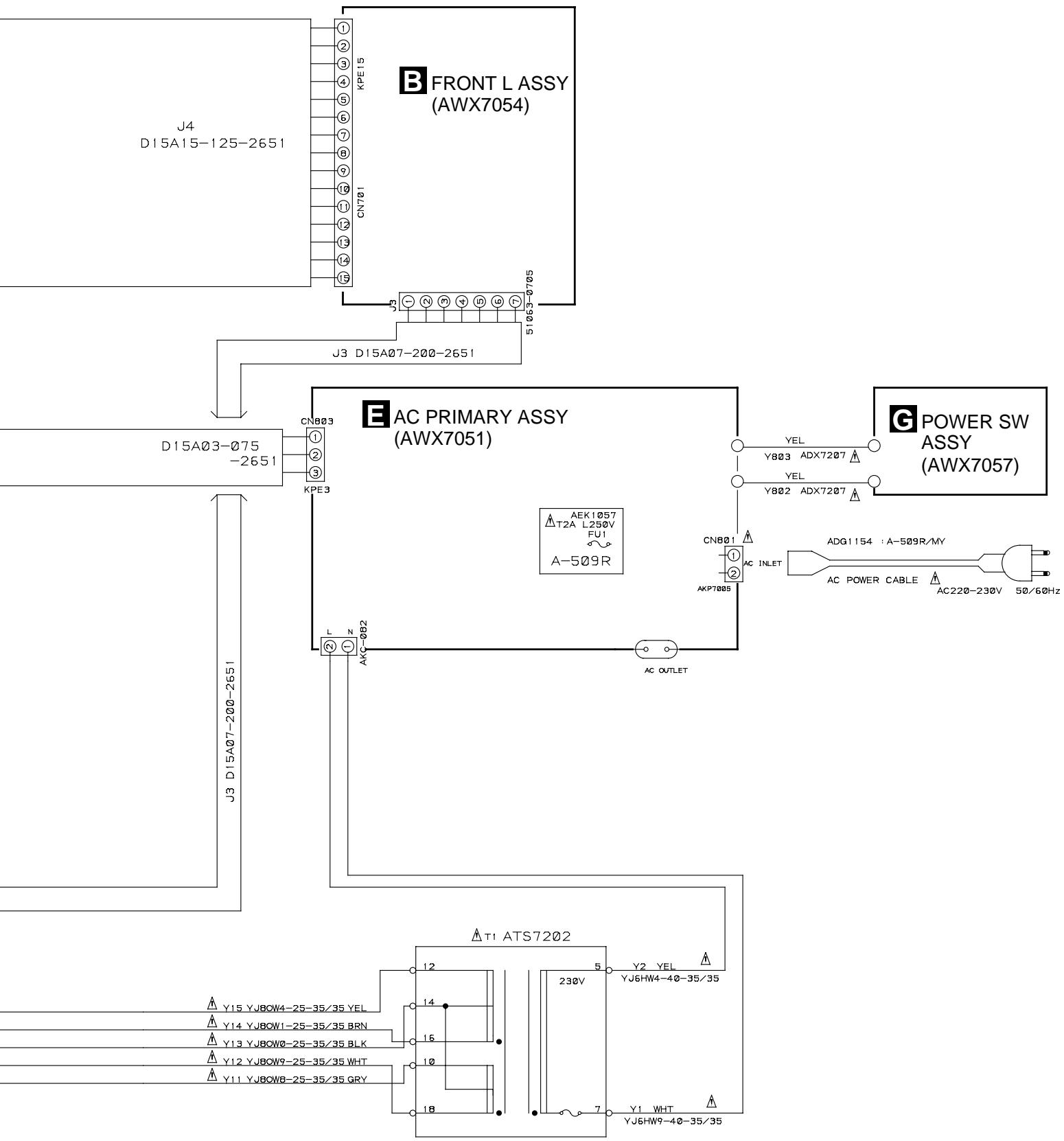
3. BLOCK DIAGRAM AND SCHEMATIC DIAGRAM
3.1 BLOCK DIAGRAM
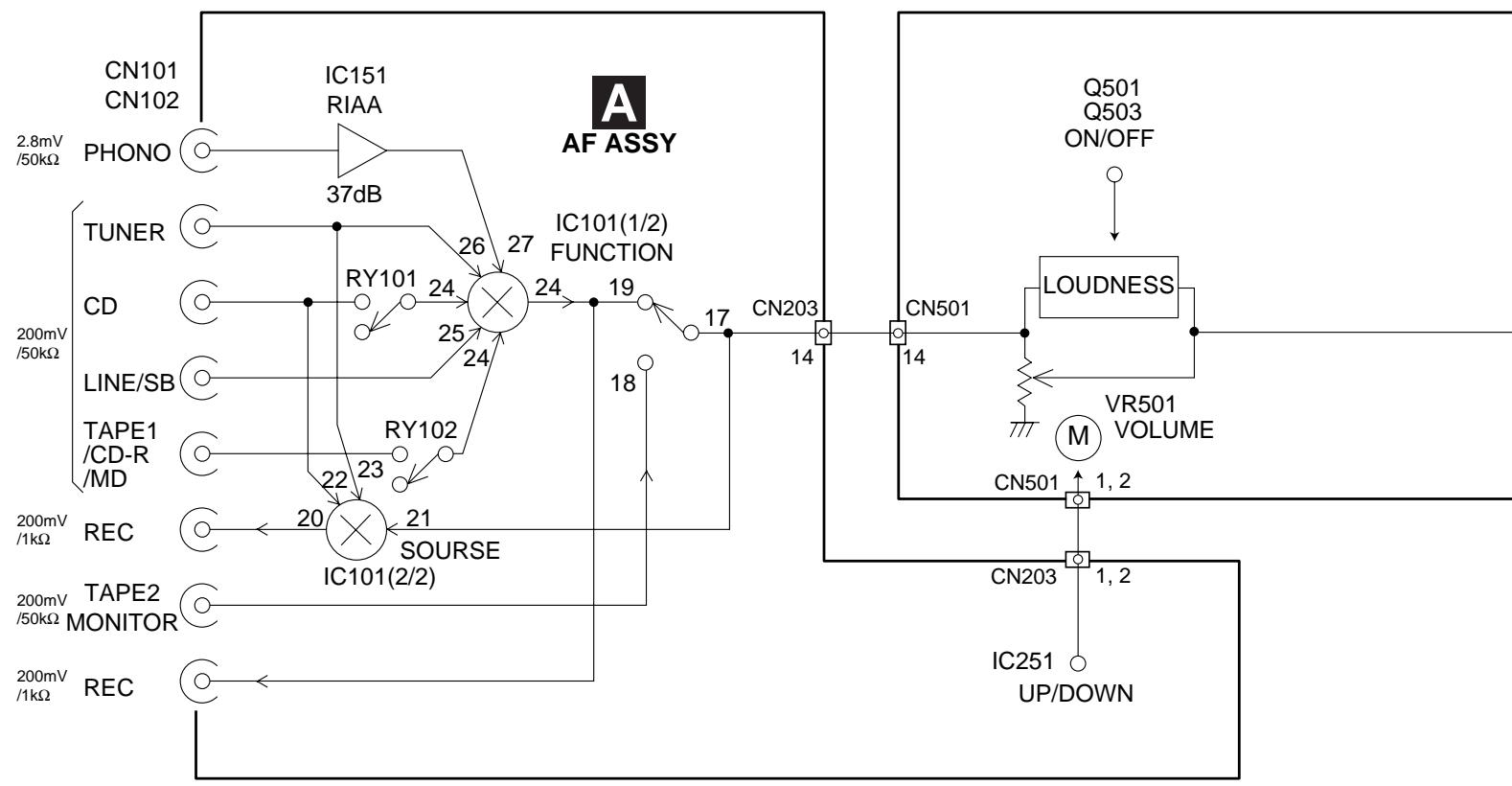

FRONT R ASSY

Q407, Q408
FROM UNUSUAL
OUTPUT DETECTION
TO FUNCTION SW

IC101

S701-S704
KEY INPUTS 23, 24,
2,3,4
DIRECT, LOUDNESS ON/OFF


Q501-Q514
S602, S603 36,40
FROMRECSEL41,42
06
VOLUME UP/DOWN

IC251
FROM FUNCTION SFL
MUTE, FUNC MUTE C

Q303
32.33
37
57
TO PROTECTION RY

Q403, Q404

604
3.2 OVERALL CONNECTION DIAGRAM
Note : When ordering service parts, be sure to refer to "EXPLODED VIEWS and PARTS LIST" or "PCB PARTS LIST".

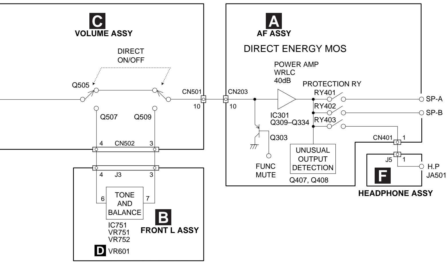
3.3 AF ASSY
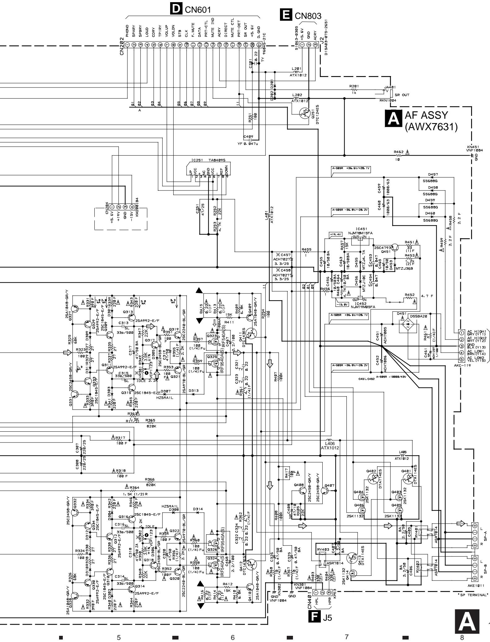
TO POWER TRANSFORMER T1
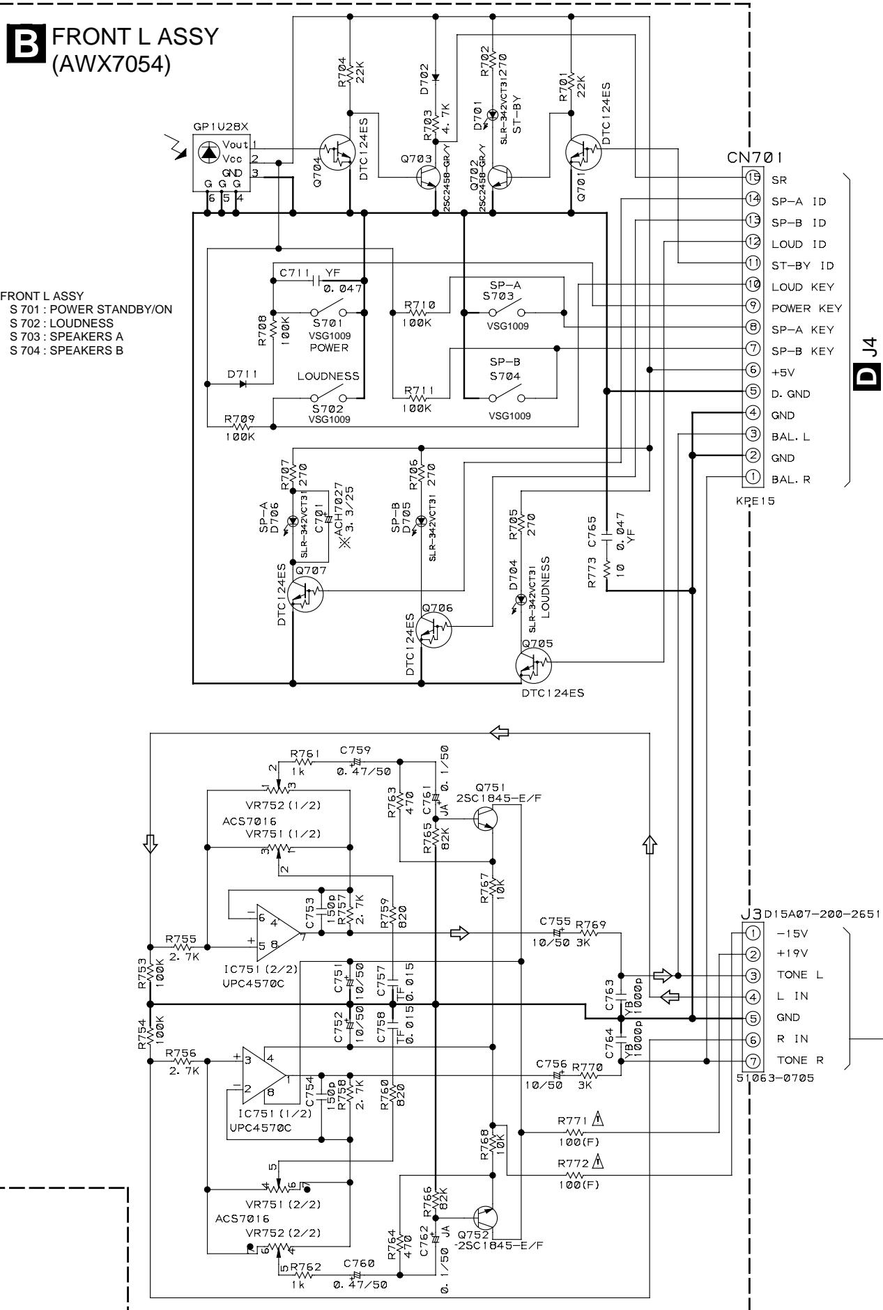
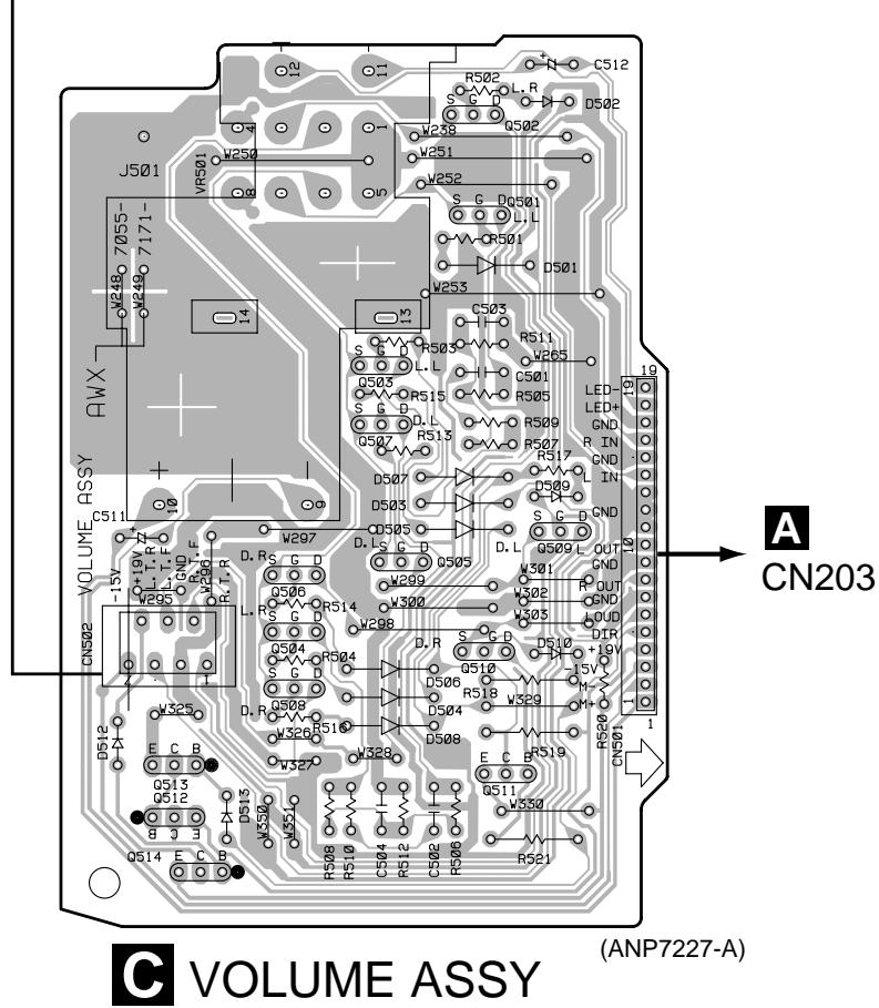
3.4 FRONT L and VOLUME ASSYS

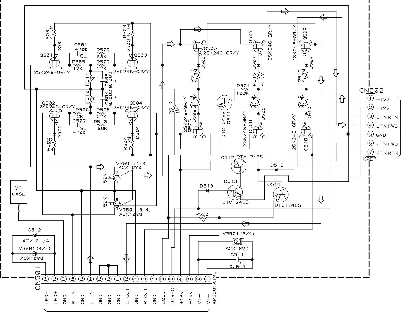
VOLUME ASSY (AWX7055)
A CN203

: AUDIO SIGNAL ROUTE
NOTES
- RESISTORS INDICATED IN Ohm 1 / 4W± 5% TOLERANCE UNLESS OTHERWISE NOTED K; KOhm F, FL: NON-FRAMABLE TYPE
2.CAPACITORS INDICATED IN CAPACITY (uF)/VOLTAGE (V) UNLESS OTHERWISE NOTED p:pF INDICATED WITHOUT VOLTAGE IS 50V EXCEPT ELECTROLYTIC CAPACITOR. TF:CFTLA TY:CFTYA JA:CEJA BA:CEBA - DIODES NO MARK DIODES ARE HSS104-02
3.5 FRONT R, AC PRIMARY, HEADPHONE and POWER SW ASSYS

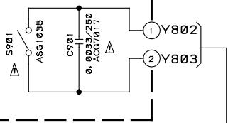
POWER SW ASSY (AWX7057)

HEADPHONE ASSY (AWX7052)
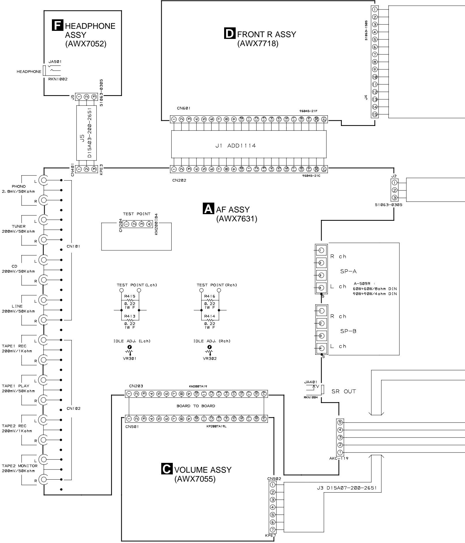
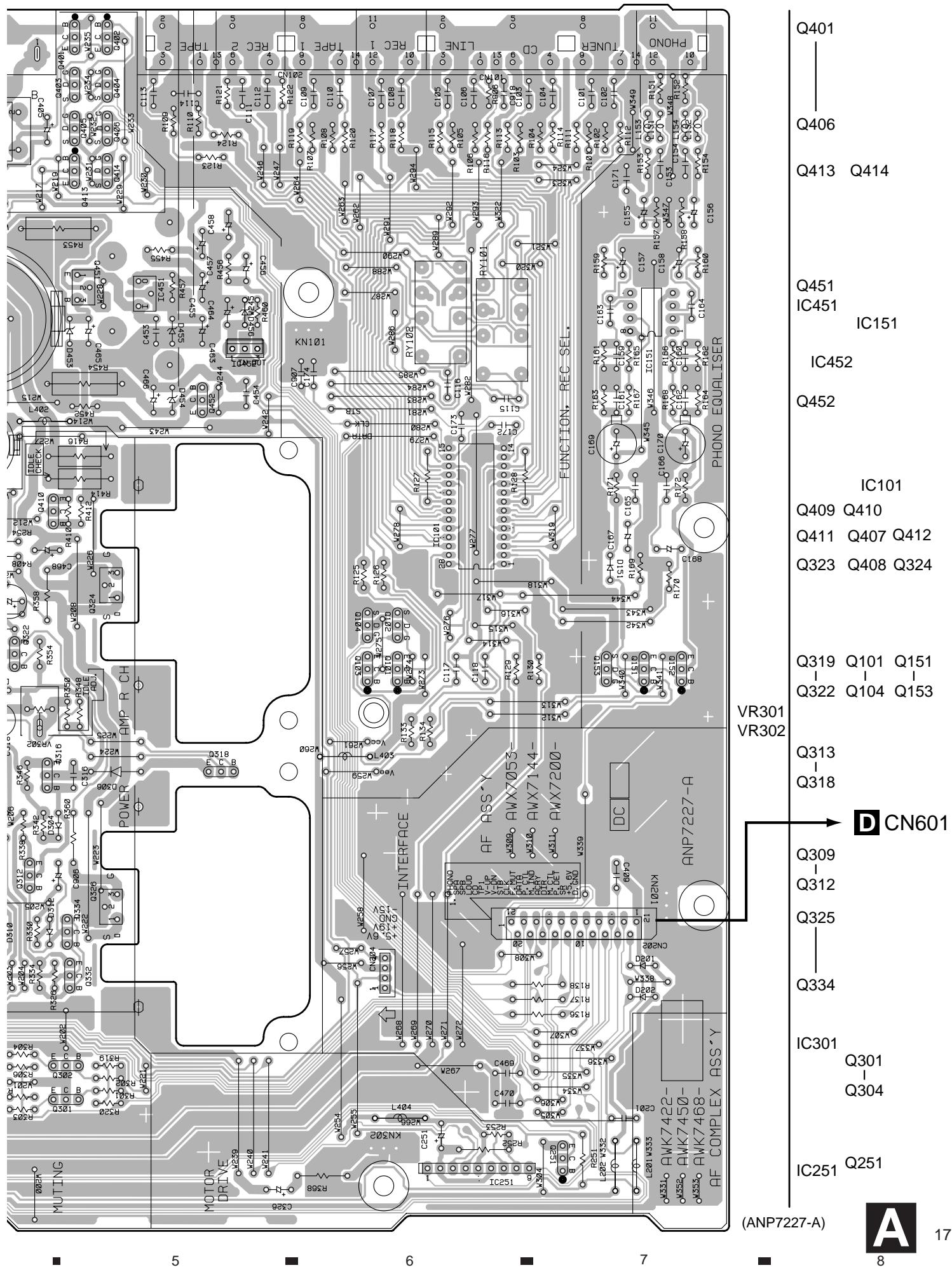
4. PCB CONNECTION DIAGRAM
4.1 AF ASSY

AF ASSY
POWER TRANSFORMER T1

CN803
NOTE FOR PCB DIAGRAMS:
- Part numbers in PCB diagrams match those in the schematic diagrams.
- A comparison between the main parts of PCB and schematic diagrams is shown below.
| Symbol in PCB Diagrams | Symbol in Schematic Diagrams | Part Name |
| B C E | B C E B C E | Transistor |
| B C E | B C E B C E | Transistor with resistor |
| D G S | D G S D G S | Field effect transistor |
| S D G 1 2 3 G | G D S G D S | MOS Field effect transistor |
| O O O O O O O O | O O O O O O O O | Resistor array |
| O O O | O O O | 3-terminal regulator |
- The parts mounted on this PCB include all necessary parts for several destination.
For further information for respective destinations, be sure to check with the schematic diagram.
4. Viewpoint of PCB diagrams
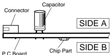
SIDE A


CN501

J5
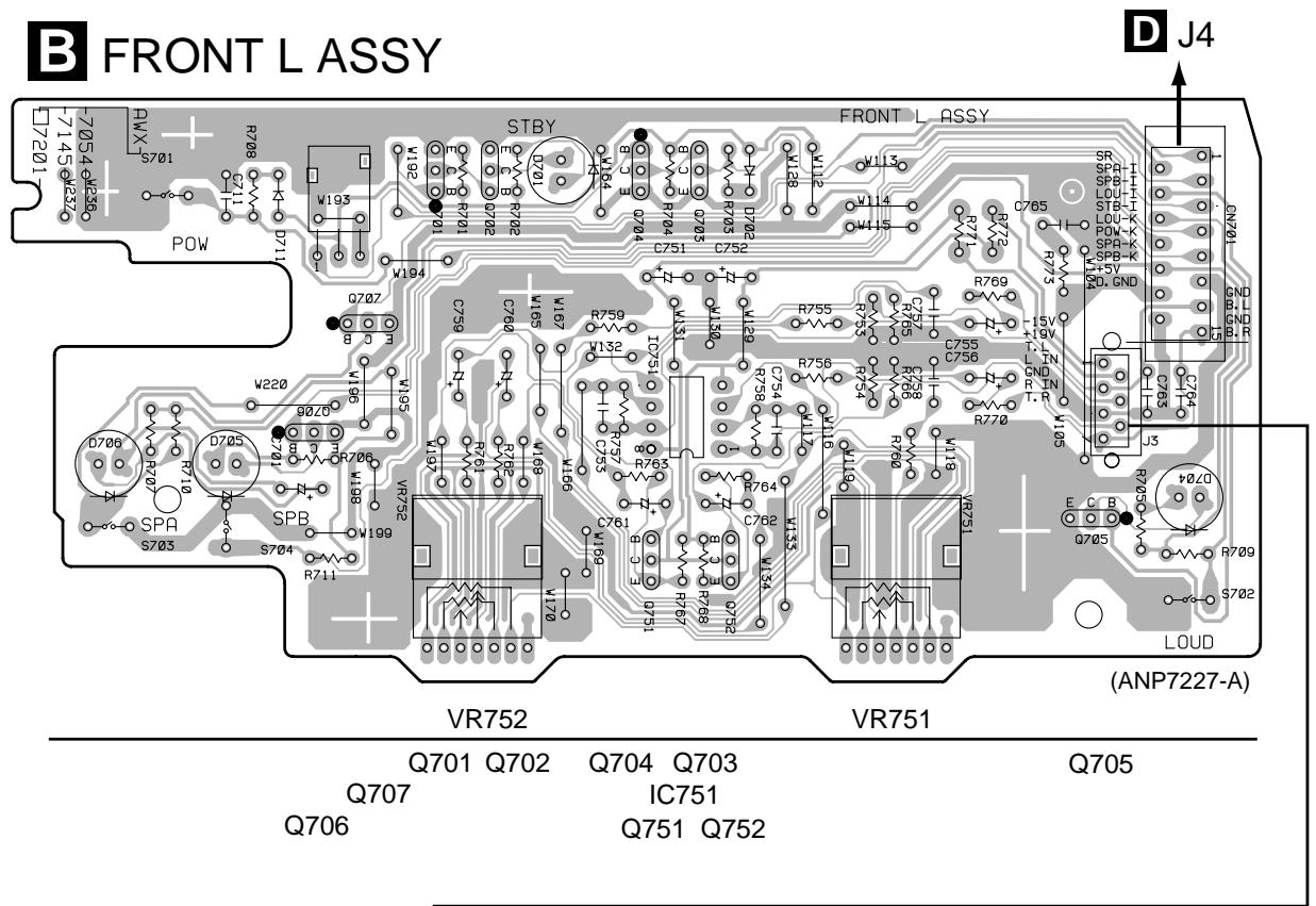
4.2 FRONT L and VOLUME ASSYS
SIDE A
Q502
Q501
Q503
Q507
Q509
Q506 Q505
Q504 Q510
Q508
Q513 Q511
Q512
Q514
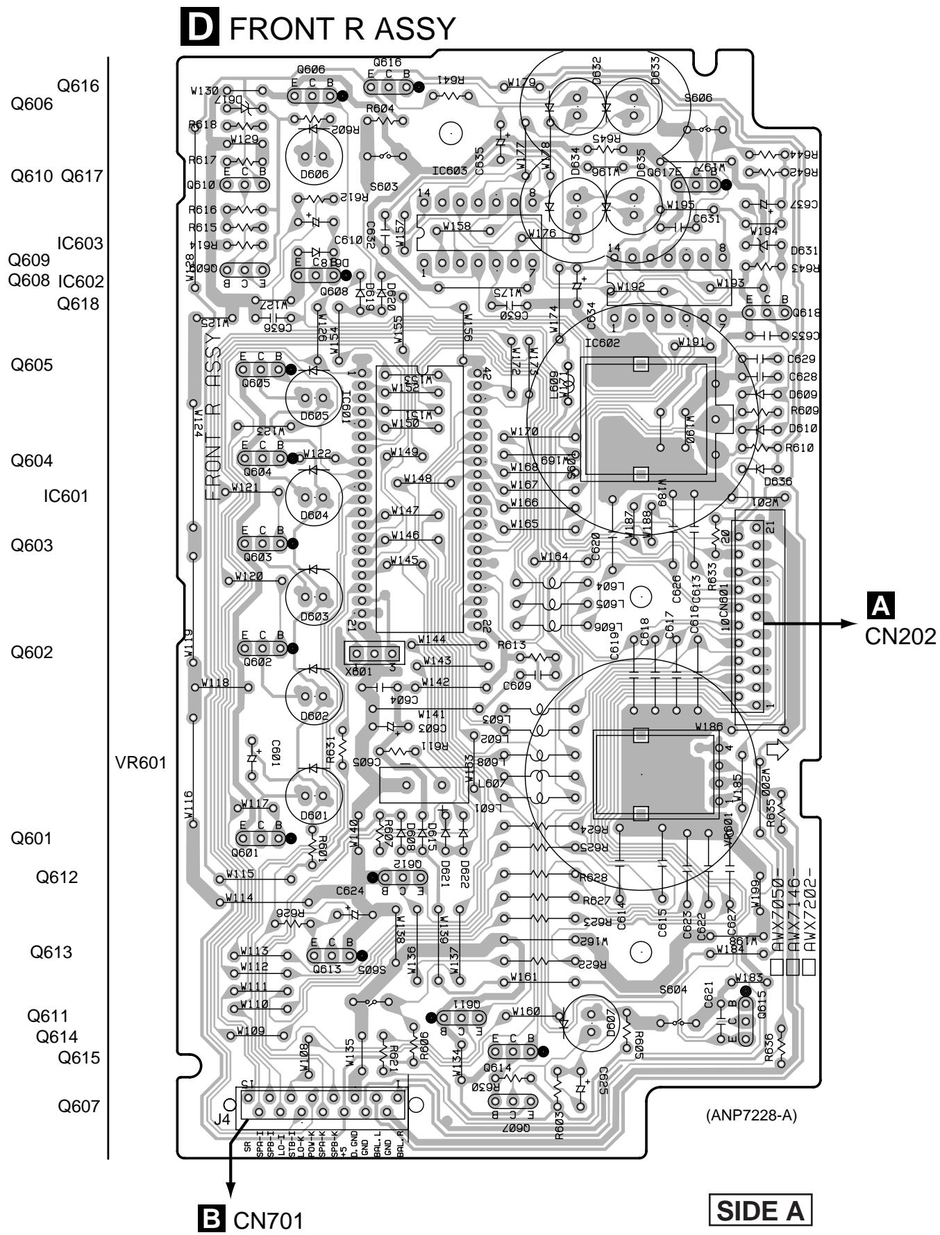
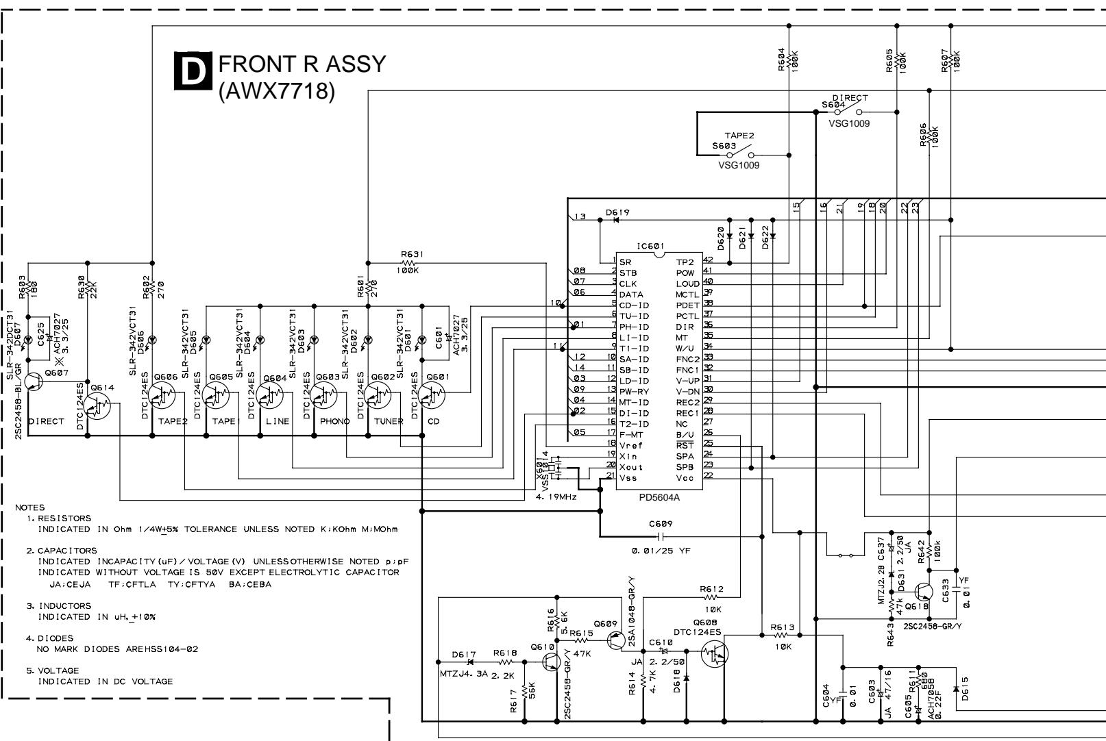
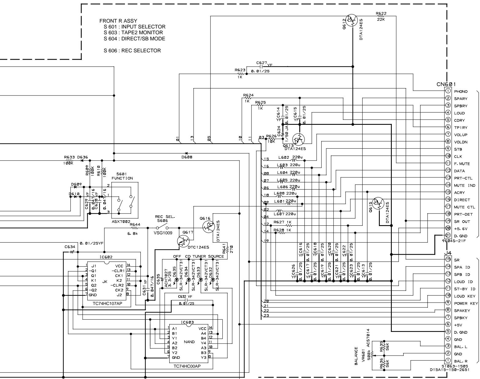
4.3 FRONT R ASSY
4.4 AC PRIMARY, HEADPHONE and POWER SW ASSYS
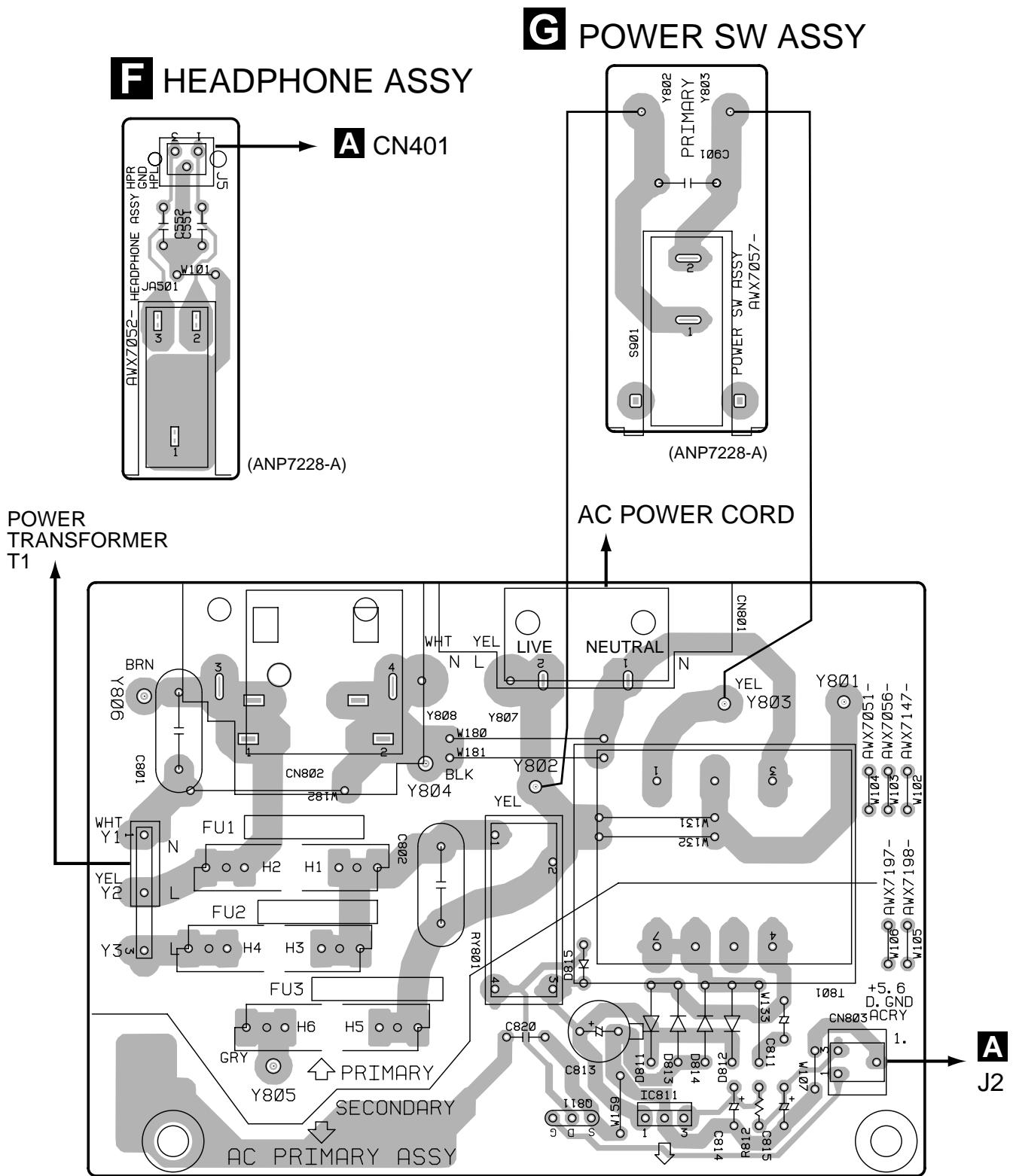

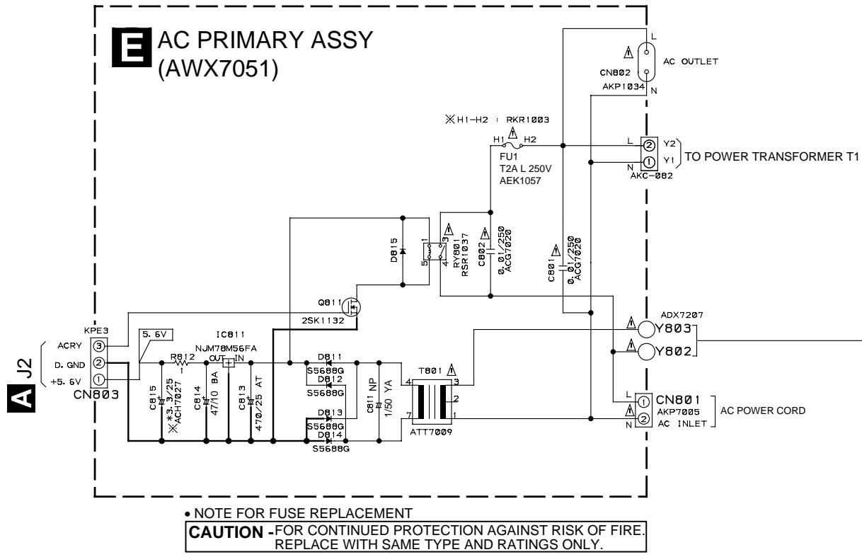
AC PRIMARY ASSY
(ANP7228-A)
Q811
IC811
SIDE A
5. PCB PARTS LIST
NOTES: Parts marked by "NSP" are generally unavailable because they are not in our Master Spare Parts List.
- The mark found on some component parts indicates the importance of the safety factor of the part. Therefore, when replacing, be sure to use parts of identical designation.
- When ordering resistors, first convert resistance values into code form as shown in the following examples.
Ex.1 When there are 2 effective digits (any digit apart from 0), such as 560 ohm and 47k ohm (tolerance is shown by J = 5% and K = 10% ).
$$ \begin{array}{l} 5 6 0 \Omega \quad \rightarrow \quad 5 6 \times 1 0 ^ {l} \quad \rightarrow \quad 5 6 1 \dots \dots \dots \dots \dots \dots \dots \dots \dots \dots \dots \dots \dots \dots \dots \dots \dots \dots \dots \dots \dots \dots \dots \dots \dots R D 1 / 4 P U [ 5 ] [ 6 ] [ 7 ] J \ 4 7 k \Omega \quad \rightarrow \quad 4 7 \times 1 0 ^ {3} \quad \rightarrow \quad 4 7 3 \dots \dots \dots \dots \dots \dots \dots \dots \dots \dots \dots \dots \dots \dots \dots \dots \dots \dots \dots \dots \dots \dots \dots \dots \dots R D I / 4 P U [ 4 ] [ 7 ] [ 3 ] J \ 0. 5 \Omega \rightarrow R 5 0 \dots \dots \dots \dots \dots \dots \dots \dots \dots \dots \dots \dots \dots \dots \dots \dots \dots \dots \dots \dots \dots \dots \dots \dots \dots \dots \dots \dots \dots \dots \dots \ I \Omega \quad \rightarrow \quad I R O \dots \dots \dots \dots \dots \dots \dots \dots \dots \dots \dots \dots \dots \dots \dots \dots \dots \dots \dots \dots \dots \dots \dots \dots \dots \dots \dots \dots \dots \dots \dots \dots \dots \dots \dots \dots \dots \dots \ \end{array} $$
Ex.2 When there are 3 effective digits (such as in high precision metal film resistors).
$$ 5. 6 2 k \Omega \rightarrow 5 6 2 \times 1 0 ^ {l} \rightarrow 5 6 2 1 \dots \dots \dots \dots \dots \dots \dots \dots \dots \dots \dots \dots \dots \dots \dots \dots \dots \dots \dots \dots \dots R N 1 / 4 P C [ 5 ] [ 6 ] [ 2 ] [ 1 ] F $$
| Mark | No. Description | Part No. |
| NSP | AF COMPLEX ASSY | AWK7625 |
| AF ASSY | AWX7631 | |
| FRONT L ASSY | AWX7054 | |
| VOLUME ASSY | AWX7055 | |
| NSP | CONTROL ASSY | AWG7022 |
| FRONT R ASSY | AWX7718 | |
| AC PRIMARY ASSY | AWX7051 | |
| NSP | HEADPHONE ASSY | AWX7052 |
| POWER SW ASSY | AWX7057 |
| Mark | No. | Description | Part No. |
| D455 | MTZJ4.7A | ||
| D457-D460 | S5688G | ||
| COILS | |||
| L201,L202,L401,L403,L405,L406 BEADS FILTER | ATX1012 | ||
| RELAGHS | |||
| RY401-RY403 | ASR7014 | ||
| RY101,RY102 | RSR1026 | ||
A AF ASSY
SEMICONDUCTORS
| IC151 | M5220P |
| IC451 | NJM78M15FA |
| IC452 | NJM79M05FA |
| IC251 | TA8409S |
| IC101 | TC9163AN |
| IC301 | UPC4570C |
| Q327, Q328, Q409, Q410 | 2SA1048 |
| Q321, Q322 | 2SA970 |
| Q311-Q314, Q329, Q330 | 2SA992 |
| Q309, Q310, Q315, Q316 | 2SC1845 |
| Q333, Q334 | 2SC1845 |
| Q319, Q320 | 2SC2240 |
| Q317, Q318, Q331, Q332 | 2SC2458 |
| Q407, Q408 | 2SC2458 |
| Q303, Q304 | 2SC2878 |
| Q451 | 2SC4793 |
| Q102, Q104, Q153, Q403-Q406 | 2SK1132 |
| Q414 | 2SK1132 |
| Q401, Q402, Q413 | DTA114ES |
| Q101, Q103, Q151 | DTA124ES |
| Q152, Q251 | DTC124ES |
| Q411, Q412 | DTC143ES |
| Q323, Q324 | IRF540A(S) |
| Q325, Q326 | IRF9540A(S) |
| D451 | D5SBA20 |
| D151, D201, D202, D301-D306 | HSS104-02 |
| D309-D314 | HSS104-02 |
| D307, D308 | HZS9A1L |
| D456 | MTZJ10C |
| D453 | MTZJ36B |
CAPACITORS
| C461 (1μF/100V) | ACH1237 |
| C457,C458 (3.3μF/25V) | ACH7027 |
| C451 (10000μF/43V) | ACH7085 |
| C452 (10000μF/43V) | ACH7086 |
| C153,C154 | CCCSL221J50 |
| C303,C304 | CCCSL221K2H |
| C313-C316 | CCCSL330K2H |
| C167,C168 | CEANP1R0M50 |
| C408 | CEANP470M10 |
| C155,C156,C465 | CEAT100M50 |
| C169,C170 | CEAT101M25 |
| C459,C460 | CEAT102M63 |
| C307,C308 | CEAT221M25 |
| C467,C468 | CEAT2R2M2A |
| C251 | CEAT470M25 |
| C157,C158 | CEAT471M6R3 |
| C305,C306,C455,C456 | CEBA100M50 |
| C463,C464 | CEBA100M50 |
| C405-C407 | CEBA2R2M50 |
| C301,C302 | CEBA3R3M50 |
| C317,C318 | CEBA470M50 |
| C325,C326 | CEBAR47M50 |
| C319,C320 | CECA470M50 |
| C115,C116,C201,C321-C324 | CFTYA224J50 |
| C161,C162,C470 | CFTYA823J50 |
| C165,C166 | CKCYB222K50 |
| C117,C118,C171,C310,C327 | CKCYF473Z50 |
| C409,C453,C454 | CKCYF473Z50 |
| C172-C174 | CKPUYB102K50 |
| C159,C160 | CQMA243J50 |
| Mark | No. | Description | Part No. |
| RESISTORS | |||
| △ | R458,R459 | RD1/4LMF2R2J | |
| △ | R133,R134,R171,R172 | RD1/4MUF101J | |
| △ | R317,R318,R351-R354,R417 | RD1/4MUF101J | |
| △ | R339-R346 | RD1/4MUF221J | |
| △ | R331-R334 | RD1/4MUF391J | |
| △ | R452 | RD1/4MUF4R7J | |
| △ | R125,R126 | RD1/4MUF821J | |
| △ | R367,R368 | RD1/4PMF100J | |
| △ | R355,R356 | RD1/4PMF222J | |
| △ | R461 | RD1/4PMF470J | |
| △ | R361,R362 | RD1/4PMF4R7J | |
| △ | R462 | RD1/4PU100J | |
| △ | R460 | RD1/4PU472J | |
| △ | R363,R364 | RDR1/2PM152J | |
| R315,R316 | RDR1/4PM561J | ||
| △ | R357-R360 | RFA1/4PS101J | |
| R349,R350 | RN1/4PC3901F | ||
| △ | R451 | RS1LMF330J | |
| △ | R413-R416 | RS1LMFR22J | |
| △ | R453 | RS2LMF122J | |
| △ | R403,R404 | RS2LMF331J | |
| VR301,VR302 (2.2kΩ) | VCP1123 | ||
| Other Resistors | RD1/4PU□□□J | ||
OTHERS
| CABLE HOLDER (3P) | 51063-0305 | |
| CN202 | 21P FFC CONNECTOR | 9604S-21C |
| SCREW | ABA-298 | |
| SCREW | ABA1007 | |
| SCREW | ABA1052 | |
| CN101, CN102 | PIN JACK(8P) | AKB7023 |
| SPEAKER TERMINAL 8-P | AKE1011 | |
| HEAT SINK M | ANH-697 | |
| HEAT SINK B | ANH1021 | |
| J2 | JUMPER WIRE | D15A03-075-2651 |
| CN204 | 4P PLUG | KM200IB4 |
| CN203 | 19P PLUG | KM200TA19 |
| CN401 | CONNECTOR (3P) | KPE3 |
| JA401 | REMOTE CONTROL JACK | RKN1004 |
| PCB BINDER | VEF1040 | |
| KN101, KN201, KN301, KN302, KN451 | VNF1084 | |
| EARTH METAL FITTING | ||
B FRONT L ASSY
SEMICONDUCTORS
| IC751 | UPC4570C |
| Q751,Q752 | 2SC1845 |
| Q702,Q703 | 2SC2458 |
| Q701,Q704-Q707 | DTC124ES |
| D702,D711 | HSS104-02 |
| D701,D704-D706 | SLR-342VCT31 |
SWITCHES
| S701-S704 | VSG1009 |
| Mark | No. | Description | Part No. |
| CAPACITORS | |||
| C701 | (3.3μF/25V) | ACH7027 | |
| C753,C754 | CCCSL151J50 | ||
| C751,C752,C755,C756 | CEAT100M50 | ||
| C759,C760 | CEATR47M50 | ||
| C761,C762 | CEJAR10M50 | ||
| C757,C758 | CFTLA153J50 | ||
| C765 | CKCYF473Z50 | ||
| C763,C764 | CKPUYB102K50 | ||
| C711 | CKPUYF473Z16 | ||
| RESISTORS | |||
| R771,R772 | RD1/4MUF101J | ||
| VR751,VR752 (30kΩ) | ACS7016 | ||
| Other Resistors | RD1/4PU□□□J | ||
| OTHERS | |||
| CABLE HOLDER (7P) | 51063-0705 | ||
| J3 | JUMPER WIRE | D15A07-200-2651 | |
| CN701 | CONNECTOR (15P) | KPE15 | |
| REMOTE RECEIVER UNIT | GP1U28X | ||
C VOLUME ASSY
SEMICONDUCTORS
| Q501-Q510 | 2SK246 |
| Q512 | DTA124ES |
| Q511,Q513,Q514 | DTC124ES |
| D501-D510,D512,D513 | HSS104-02 |
CAPACITORS
| C501,C502 | CCCSL471J50 |
| C512 | CEBA470M10 |
| C503,C504 | CFTYA823J50 |
| C511 | CKCYF473Z50 |
RESISTORS
| VR501 (50kΩ) | ACX1090 |
| Other Resistors | RD1/4PU□□□J |
| RS | |
| CN501 19P SOCKET | KP200TA19L |
| CN502 CONNECTOR (7P) | KPE7 |
D FRONT R ASSY
SEMICONDUCTORS
| IC601 | PD5604A |
| IC603 | TC74HC00AP |
| IC602 | TC74HC107AP |
| Q609 | 2SA1048 |
| Q607,Q610,Q618 | 2SC2458 |
| Q612,Q613,Q615,Q616 | DTA124ES |
| Q601-Q606,Q608,Q614,Q617 | DTC124ES |
| D608-D610,D615,D618-D622 | HSS104-02 |
| D636 | HSS104-02 |
| D631 | MTZJ2.2B |
| D617 | MTZJ4.3A |
| D607 | SLR-342DCT31 |
| D601-D606,D632-D635 | SLR-342VCT31 |
| Mark No. | Description | Part No. |
| COILS | ||
| L601-L608 | LAU221J | |
| SWITCHES | ||
| S603,S604,S606 | VSG1009 | |
| S601 | ASX7002 | |
| CAPACITORS | ||
| C601,C625,C635 (3.3μF/25V) | ACH7027 | |
| C605 (0.22F) | ACH7058 | |
| C624 | CEJA1R0M50 | |
| C610,C637 | CEJA2R2M50 | |
| C603 | CEJA470M16 | |
| C604 | CKCYF103Z50 | |
| C609,C613-C623,C626,C627 | CKPUYF103Z25 | |
| C632-C634 | CKPUYF103Z25 | |
| C628,C629,C631 | CKPUYF473Z16 | |
| RESISTORS | ||
| VR601 (500KΩ) | ACS7014 | |
| Other Resistors | RD1/4PU□□□J | |
| OTHERS | ||
| X601 | CERAMIC RESONATOR (4.19MHz) | VSS1014 |
| CABLE HOLDER (15P) | 51063-1505 | |
| CN601 | 21P FFC CONNECTOR | 9604S-21F |
| J4 | JUMPER WIRE | D15A15-125-2651 |
| E AC PRIMARY ASSY | ||
| SEMICONDUCTORS | ||
| IC811 | NJM78M56FA | |
| Q811 | 2SK1132 | |
| D815 | HSS104-02 | |
| D811-D814 | S5688G | |
| TRANSFORMER | ||
| T801 | ATT7009 | |
| RELAY | ||
| RY801 | RSR1037 | |
| CAPACITORS | ||
| C801,C802 (0.01μF/AC250V) | ACG7020 | |
| C815 (3.3μF/25V) | ACH7027 | |
| C813 | CEAT471M25 | |
| C814 | CEBA470M10 | |
| C811 | CEYANP1R0M50 | |
| RESISTORS | ||
| All Resistors | RD1/4PU□□□J | |
| OTHERS | ||
| Y802,Y803 BOARDIN READ WIRE | ADX7207 | |
| CN802 AC SOCKET 1P | AKP1034 | |
| CN801 AC INLET | AKP7005 | |
| CN803 CONNECTOR (3P) | KPE3 | |
| H1,H2 FUSE HOLDER | RKR1003 | |
| Mark No. | Description | Part No. |
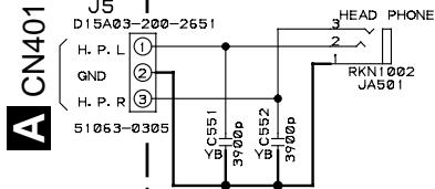
| HEADPHONE ASSY CAPACITORS C551,C552 | CKCYB392K50 | |
| OTHERS CABLE HOLDER (3P) J5 JUMPER WIRE JA501 HEADPHONE JACK | 51063-0305 D15A03-150-2651 RKN1002 | |
| POWER SW ASSY SWITCH Δ S901 | ASG1035 | |
| CAPACITOR Δ C901 (0.0033μF/AC250V) | ACG7017 | |
6. ADJUSTMENTS
6.1 IDLE CURRENT ADJUSTMENT
- CAUTION: Heatsinks' (Q323-Q326) DC level is equal to +B or -B.
Don't touch them or you will be electricary chocked.
- Connect the measuring instrument as Fig.6-1. (R415 or R416)
- Set the VOLUME CONTROL to minimum, BASS TONE CONTROL to center, TREBLE TONE CONTROL to center and BALANCE CONTROL to center. Set VR301 and VR302 to minimum.
- Set the POWER switch to ON.
- Adjust VR301 (VR302) so that the voltage between both sides of R415 (R416) becomes 16mV± 1mV . (Within 10 seconds from when the relay is turned ON)
- Ages for 7 minutes.
- Adjust VR301 (VR302) so that the voltage between both sides of R415 (R416) becomes 11mV± 1mV .
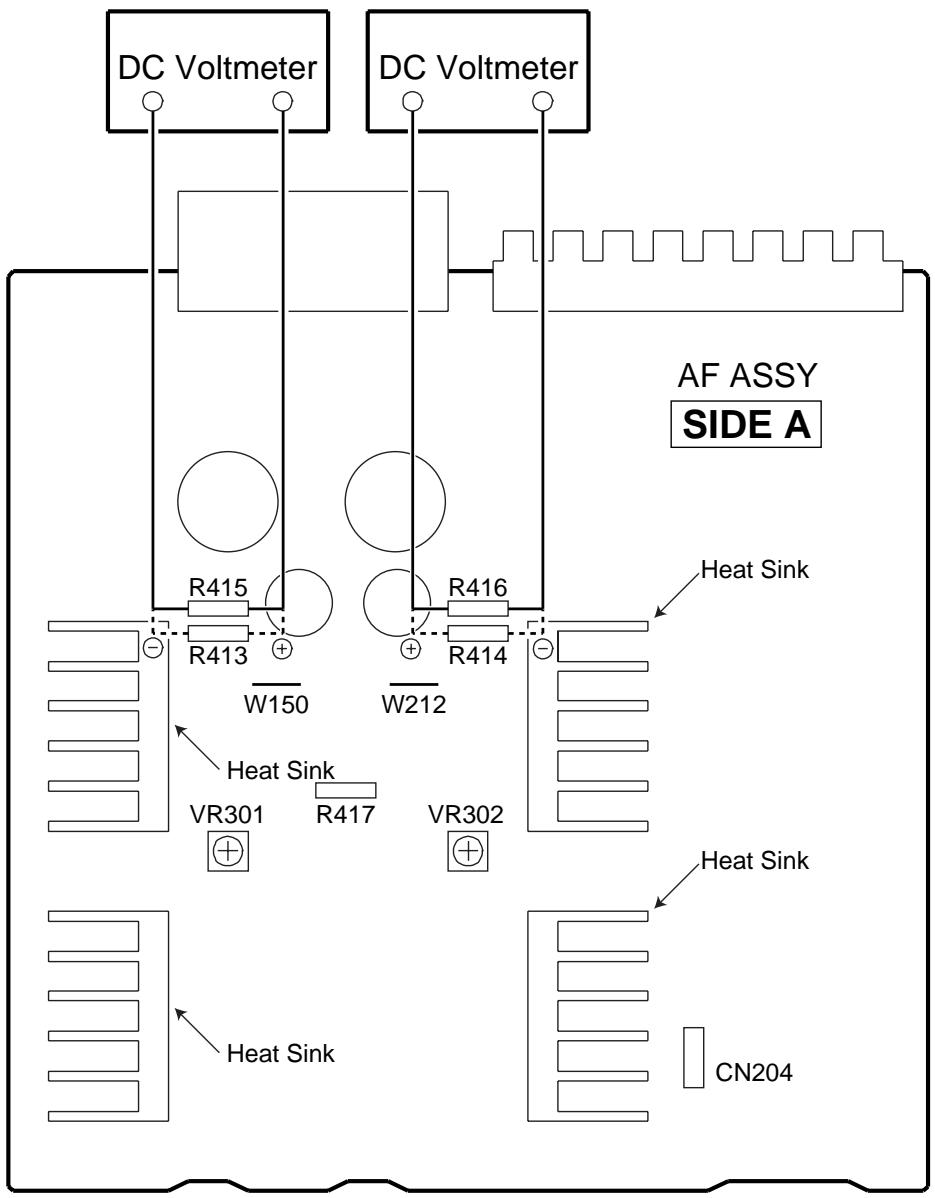
Fig.6-1 Adjustment Method
7. GENERAL INFORMATION
7.1 IC
PD5604A (FRONT R ASSY : IC601)
-
REMOTE CONTROL AMP MICROCOMPUTER
-
The information shown in the list is basic information and may not correspond exactly to that shown in the schematic diagrams.
- Pin Assignment (Top view)
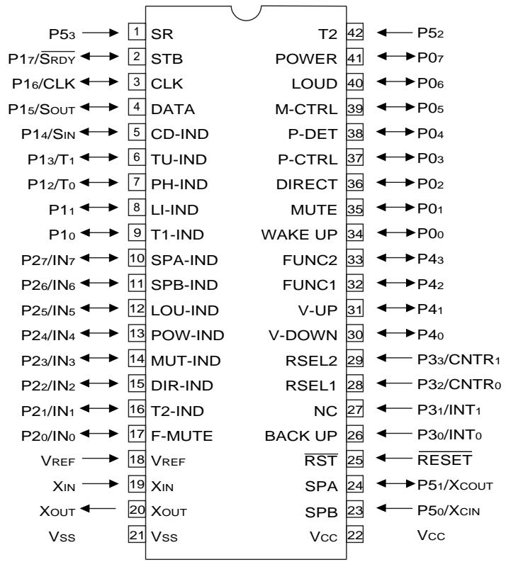
Pin Function
| No. | Pin name | I/O | Function |
| 1 | P53 | I | Remote control signal input pin. |
| 2 | P17/SRDY | O | STB for TC9163N. |
| 3 | P16/CLK | O | CLOCK for TC9163N. |
| 4 | P15/SOUT | O | DATA for TC9163N. |
| 5 | P14/SIN | O | CD INDICATOR. |
| 6 | P13/T1 | O | TUNER INDICATOR. |
| 7 | P12/T0 | O | PHONO INDICATOR. |
| 8 | P11 | O | LINE INDICATOR. |
| 9 | P10 | O | TAPE1 INDICATOR. |
| 10 | P27/IN7 | O | SPEAKER-A INDICATOR. |
| 11 | P26/IN6 | O | SPEAKER-B INDICATOR. |
| 12 | P25/IN5 | O | LOUDNESS INDICATOR. |
| 13 | P24/IN4 | O | POWER (STAND-BY) INDICATOR. |
| 14 | P23/IN3 | O | MUTE INDICATOR.MUTE ON: Repeats H and L every 1 second.Normal : “H” |
| 15 | P22/IN2 | O | DIRECT INDICATOR. |
| 16 | P21/IN1 | O | TAPE2 INDICATOR. |
| 17 | P20/IN0 | O | FUNCTION switch MUTE. |
| 18 | VREF | I | Pulls up to 5V. |
| 19 | XIN | I | 4.19MHz . |
| 20 | XOUT | O | Ceramic vibrating and connecting terminal. |
| 21 | VSS | - | Digatal GND. |
| 22 | VCC | - | Power supply +5V. |
| 23 | P50/XCIN | I | SPEAKER-B KEY input. |
| No. | Pin name | I/O | Function |
| 24 | P51/XOUT | I | SPEAKER-A KEY input. |
| 25 | RESET | I | Reset pin. |
| 26 | P30/INT0 | I | BACK UP detection pin. interrupt specification. |
| 27 | P31/INT1 | O | Not used. |
| 28 | P32/CNTR0 | I | REC selector input 1. |
| 29 | P33/CNTR1 | I | REC selector input 2. interrupt specification. |
| 30 | P40 | O | Volume DOWN data output. |
| 31 | P41 | O | Volume UP data output. |
| 32 | P42 | I | FUNCTION selector input 1. |
| 33 | P43 | I | FUNCTION selector input 2. |
| 34 | PO0 | I | WAKE UP input. Key on wake up specification. |
| 35 | PO1 | I | MUTE KEY input. Key on wake up specification. |
| 36 | PO2 | I | DIRECT KEY input. Key on wake up specification. |
| 37 | PO3 | O | Protection control pin. |
| 38 | PO4 | I | Output error detection pin |
| 39 | PO5 | O | MUTING control pin. |
| 40 | PO6 | I | LOUDNESS KEY input. Key on wake up specification. |
| 41 | PO7 | I | POWER KEY input. Key on wake up specification. |
| 42 | P52 | I | TAPE2 KEY input. |
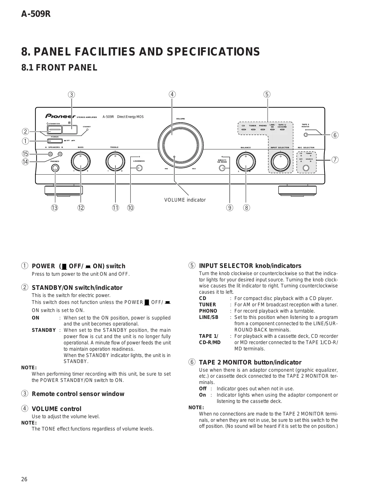
8. PANEL FACILITIES AND SPECIFICATIONS
8.1 FRONT PANEL
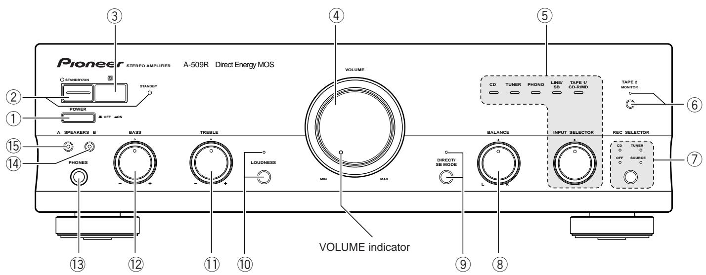
① POWER (OFF/ON) switch
Press to turn power to the unit ON and OFF.
② STANDBY/ON switch/indicator
This is the switch for electric power.
This switch does not function unless the POWER OFF/
ON switch is set to ON.
ON : When set to the ON position, power is supplied and the unit becomes operational.
STANDBY : When set to the STANDBY position, the main power flow is cut and the unit is no longer fully operational. A minute flow of power feeds the unit to maintain operation readiness.
When the STANDBY indicator lights, the unit is in STANDBY.
NOTE:
When performing timer recording with this unit, be sure to set the POWER STANDBY/ON switch to ON.
③ Remote control sensor window
(4) VOLUME control
Use to adjust the volume level.
NOTE:
The TONE effect functions regardless of volume levels.
⑤ INPUT SELECTOR knob/indicators
Turn the knob clockwise or counterclockwise so that the indicator lights for your desired input source. Turning the knob clockwise causes the lit indicator to right. Turning counterclockwise causes it to left.
CD : For compact disc playback with a CD player.
TUNER : For AM or FM broadcast reception with a tuner.
PHONO : For record playback with a turntable.
LINE/SB : Set to this position when listening to a program from a component connected to the LINE/SURROUND BACK terminals.
TAPE 1/ : For playback with a cassette deck, CD recorder CD-R/MD or MD recorder connected to the TAPE 1/CD-R/ MD terminals.
⑥ TAPE 2 MONITOR button/indicator
Use when there is an adaptor component (graphic equalizer, etc.) or cassette deck connected to the TAPE 2 MONITOR terminals.
Off : Indicator goes out when not in use.
On : Indicator lights when using the adaptor component or listening to the cassette deck.
NOTE:
When no connections are made to the TAPE 2 MONITOR terminals, or when they are not in use, be sure to set this switch to the off position. (No sound will be heard if it is set to the on position.)
⑦ REC SELECTOR switch /indicator(For TAPE 1/CD-R/MD terminals)
This switch is used to select the recording source component. The signal from the selected component is output at the TAPE1/ CD-R/MD jacks for recording. To select a recording source component, press the REC SELECTOR switch so that the indicator of the desired source component lights up. When this switch is set to [TUNER] or [CD], the signal from the selected component can be recorded regardless of the input selector switch and TAPE2 MONITOR button settings.
CD : To record from the equipment connected to the CD terminals.
TUNER : To record from the equipment connected to the TUNER terminals.
SOURCE: To record from the equipment selected by the INPUT SELECTOR knob.
OFF : In this position, nothing from the REC terminals of TAPE 1/CD-R/MD is output. Set to this position when not recording; the cassette deck will be disconnected, improving sound quality.
NOTE:
The function selected using the INPUT SELECTOR knob will be recorded irrespective of the position of the REC SELECTOR switch (TAPE 2 MONITOR terminals).
⑧ BALANCE control
Should normally be left in the center position. Adjust the balance if the sound is louder from one of the speakers. If the right side is louder, turn toward the L (left) position and if the left side is louder, turn toward the R (right) position.
NOTE:
This control does not operate at DIRECT ON mode.
⑨ DIRECT/SB MODE button/indicator
Press and hold the button for more than 3 seconds to switch SB mode ON. (Volume indicator goes out)
Press and hold the button for more than 3 seconds again to switch SB mode OFF. (Volume indicator lights)
[DIRECT]
Use this button when you do not wish to pass the output from input terminal equipment through the various frequency adjusting circuits (BASS, TREBLE, BALANCE, LOUDNESS).
On : The indicator lights. The signals input through the input terminals are reproduced without passing through the various frequency adjusting circuits. This results in flat, pure sound which is a more faithful reproduction of the input source.
Off : The indicator goes out. The signal passes through the various frequency adjusting circuits.
[SB MODE]
The SB mode is a special mode in which the amplifier does not accept remote control except power ON/OFF (But all of the facilities can be controlled by manual as same as SB mode OFF.).
Fix the VOLUME control near the center position. In this mode, the set can be used as a power amplifier which amplifies the LINE/SURROUND BACK input (the function name is LINE/SB) with a input sensitivity of 1V.
For example, when the set is combined with one of Pioneer's Surround Back compatible receiver, the set can be used sa the Surround Back amplifier.
(For details, please refer to the instruction manual of the receiver.)
⑩ LOUDNESS button/indicator
Use when listening at low volume level.
On : The indicator lights. Boosts low and high frequencies to give added punch to playback even at low volume level.
Off : The indicator goes out. Should normally be left in this position.
NOTE:
This button does not operate at DIRECT ON mode.
TREBLE tone control
Use to adjust the high-frequency tone. The center position is the flat (normal) position. When turned to the right, the high-frequency tone is emphasized; when turned to the left, the high-frequency tone is de-emphasized.
NOTE:
This control does not operate at DIRECT ON mode.
BASS tone control
Use to adjust the low-frequency tone. The center position is the flat (normal) position. When turned to the right, the low-frequency tone is emphasized; when turned to the left, the low-frequency tone is de-emphasized.
NOTE:
This control does not operate at DIRECT ON mode.
13 PHONES jack
When using headphones, insert the plug into this jack.
14 SPEAKERS B (ON/OFF) button/indicator
Use this button to listen to the speaker system connected to the SPEAKERS B terminals.
On : The indicator lights. Sound is heard from the speaker system.
Off : The indicator goes out. No sound is heard from the speaker system. Set to this position when listening with headphones.
15 SPEAKERS A (ON/OFF) button/indicator
Use this button to listen to the speaker system connected to the SPEAKERS A terminals.
On : The indicator lights. Sound is heard from the speaker system.
Off : The indicator goes out. No sound is heard from the speaker system. Set to this position when listening with headphones.
8.2 REAR PANEL
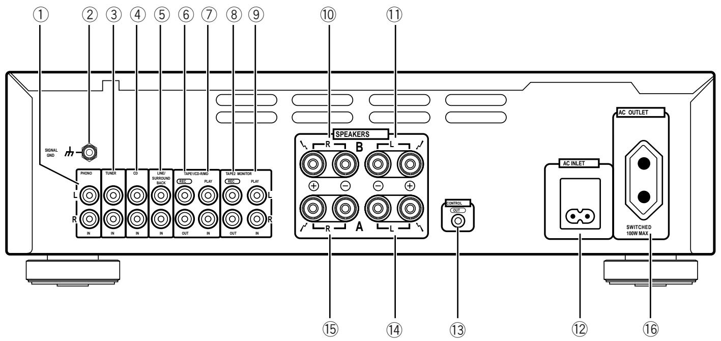
① PHONO terminals
② SIGNAL GND (Turntable ground) terminal
(3) TUNER terminals
④ CD terminals
LINE/SURROUND BACK terminals
⑥ TAPE 1/CD-R/MD REC (OUT) terminals
⑦ TAPE 1/CD-R/MD PLAY (IN) terminals
⑧ TAPE 2 MONITOR REC (OUT) terminals
⑨ TAPE 2 MONITOR PLAY (IN) terminals
10 SPEAKERS B terminals (Right channel)
⑪ SPEAKERS B terminals (Left channel)
⑫ AC INLET jack
Connect one end of the power cord to here and the other end to an AC wall socket, or the AC outlet of an audio timer. If you are going to be away from home for a long period of time, disconnect the unit from the wall socket.
13 CONTROL OUT jack
This jack is for outputting control signals when operating other components bearing the mark with the amplifier's remote control unit.
14 SPEAKERS A terminals (Left channel)
15 SPEAKERS A terminals (Right channel)
⑥ AC OUTLET
8.3 REMOTE CONTROL
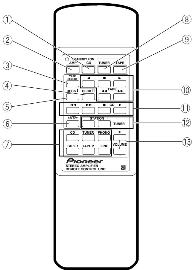
① CD POWER button
Switches CD player power STANDBY/ON.
② AMP POWER button
Switches the amplifier power STANDBY/ON.
③ TAPE SELECT button
Selects the cassette No. (1 to 6) for a multi-cassette changer.
④ DECK II button
To operate Deck II, press this button before pressing the operating buttons. Also, when using a single deck, press this button before pressing the operating buttons.
⑤ DECK I button
To operate Deck I, press this button before pressing the operating buttons.
⑥ DISC SELECT button
Press this to select discs on a multi or twin tray compact disc player.
⑦ Input selector buttons
Use to select the playback source.
CD : For compact disc playback with a CD player.
TUNER : For AM or FM broadcast reception with a tuner.
PHONO : For record playback with a turntable.
TAPE 1: For playback with a cassette deck, CD recorder or MD recorder connected to the TAPE 1/CD-R/MD terminals.
TAPE 2: For playback with a cassette deck or adaptor connected to the TAPE 2 MONITOR terminals.
LINE : For playback with a component connected to the LINE/SURROUND BACK terminal.
(8) TUNER POWER button
Switches TUNER power STANDBY/ON.
⑨ TAPE POWER button
Switches the cassette deck power STANDBY/ON.
10 TAPE operation buttons
:Playback in the direction of the arrows.
:Stop
: Tape fast forward/reverse.
CD player operation buttons
: Returns you to the start of the current track (Track search).
▶▶: Takes you to the start of the next track (Track search).
:Stop
:Play
⑫ STATION+, - buttons (TUNER)
Calls each station number in sequence.
⑬ VOLUME +, - buttons
- Increases the volume.
Decreases the volume.
NOTE:
When the accessory remote control unit is used to operate other PIONEER components with the mark, it cannot be used to operate functions which do not correspond to the functions listed on the remote control unit.
8.4 SPECIFICATIONS
Amplifier Section
Continuous power output
both channels driven at 20Hz to 20kHz)^**
T.H.D. 0.06% ,8 45W+45W*
T.H.D. 0.09% 4Ω 65W+65W*
DIN Continuous power output (both channels driven at 1 kHz)
T.H.D. 1.0% ,8 60W+60W
T.H.D. 1.0% 4Ω 90W+90W
Total harmonic distortion**
20 Hz to 20 kHz, 20 W, 8 Ω . 0.05%*
- Power output specification is for when power supply is 230V.
Input sensitivity/ impedance
PHONO (MM) 2.8 mV/50 kΩ
CD, TUNER, LINE/SB, TAPE 1/CD-R/MD
TAPE 2 MONITOR 200 mV/50 kΩ
PHONO (MM) overload level
1 kHz, T.H.D. 0.1 % 150 mV
Output level/ impedance
TAPE 1/CD-R/MD, TAPE 2 MONITOR output
200 mV/1 kΩ
Frequency response
PHONO (MM) 20 Hz to 20 kHz ± 0.5 dB
CD, TUNER, LINE/SB, TAPE 1/CD-R/MD
TAPE 2 MONITOR 5 Hz to 100 kHz ^+0_-3 dB*
Tone control
BASS. ±8 dB (100 Hz)
TREBLE. ±8 dB (10 kHz)
Loudness contour (volume control set at -30 dB position)
+5dB(100Hz)/+3dB(10kHz)
Signal-to-Noise ratio (IHF short circuit, A network)
PHONO (MM, 5 mV input) 86 dB*
CD, TUNER, LINE/SB, TAPE 1/CD-R/MD
TAPE 2 MONITOR 106 dB*
Signal-to-Noise ratio (DIN, continuous power/ 50 mW)
PHONO (MM) 71 dB/67 dB*
CD, TUNER, LINE/SB, TAPE 1/CD-R/MD,
TAPE 2 MONITOR 95 dB/71 dB*
Power Supply/ Miscellaneous
Power requirements AC 220 - 230 V, 50/60 Hz
Power consumption 160 W
Power consumption in standby mode 1 W
AC outlet
Switched(x1) 100W
Dimensions (including knobs and other protruding parts)
Weight (without package)
6.9 kg
Accessories
Remote control unit 1
Batteries (AA/R6P) 2
Operating instructions 1
Power cord(Rated current 2.5 A) 1
Warranty card 1
NOTE:
Specifications and design subject to possible modification without notice, due to improvements.
- Measured with the DIRECT/SB MODE button set to on. (at DIRECT ON mode, SB OFF mode)
** Measured by Audio Spectrum Analyzer.
- ACCESSORIES

Power cord (ADG1154)
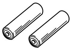
Batteries (AA/R6P)
(VEM-013)
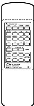
Remote control unit
(CU-A018)
(AXD7187)

- CONTENTS
- SAFETY INFORMATION
- WARNING
- NOTICE
- REMARQUE
- LEAKAGE CURRENT CHECK
- PRODUCT SAFETY NOTICE
- EXPLODED VIEWS AND PARTS LIST
- PACKING
- - PACKING PARTS LIST
- EXTERIOR
- BLOCK DIAGRAM AND SCHEMATIC DIAGRAM
- BLOCK DIAGRAM
- NOTES
- PCB CONNECTION DIAGRAM
- AF ASSY
- NOTE FOR PCB DIAGRAMS:
- Viewpoint of PCB diagrams
- AC PRIMARY, HEADPHONE and POWER SW ASSYS
- PCB PARTS LIST
- A AF ASSY
- SEMICONDUCTORS
- CAPACITORS
- B FRONT L ASSY
- C VOLUME ASSY
- D FRONT R ASSY
- ADJUSTMENTS
- IDLE CURRENT ADJUSTMENT
- GENERAL INFORMATION
- IC
- PD5604A (FRONT R ASSY : IC601)
- - Pin Assignment (Top view)
- Pin Function
- PANEL FACILITIES AND SPECIFICATIONS
- FRONT PANEL
- ⑦ REC SELECTOR switch /indicator(For TAPE 1/CD-R/MD terminals)
- NOTE:
- ⑧ BALANCE control
- ⑨ DIRECT/SB MODE button/indicator
- [DIRECT]
- [SB MODE]
- ⑩ LOUDNESS button/indicator
- TREBLE tone control
- BASS tone control
- PHONES jack
- SPEAKERS B (ON/OFF) button/indicator
- SPEAKERS A (ON/OFF) button/indicator
- REAR PANEL
- REMOTE CONTROL
- SPECIFICATIONS
- Amplifier Section
- - Power output specification is for when power supply is 230V.
- Power Supply/ Miscellaneous
- Accessories
- - ACCESSORIES
Brand : PIONEER
Model : A-509R
Category : Audio Amplifier