
MTP 1500RL 15HD A SEQ - Audiovisual Equipment Extron - Free user manual and instructions
Find the device manual for free MTP 1500RL 15HD A SEQ Extron in PDF.


| Product Type | Mini Twisted Pair Receiver with Audio and Skew Equalization (SEQ) |
| Video Support | RGB, component video (bi-level or tri-level sync), S-video, composite video up to UXGA and 1080p |
| Audio Support | Mono audio via 5-pole captive screw connector |
| Input Connector | RJ-45 (twisted pair) |
| Output Connector | 15-pin HD female (RGB) |
| Power Supply | External 12 VDC, 1 A power supply (100-240 VAC, 50/60 Hz input) |
| Peaking Adjustment | Front panel control affecting picture sharpness; LED indicates minimum/maximum |
| Level Adjustment | Front panel control to alter video output voltage for brightness |
| Skew Delay Compensation | Up to 62 ns in 2 ns steps; adjustable for red, green, or blue signals (SEQ model) |
| Daisy-Chain Capability | Up to 8 receivers via buffered RJ-45 output |
| DIP Switch Configuration | For sync polarity (positive/negative) and output format (RGBHV, RGBS, RGsB, component, S-video, composite) |
| Dimensions (H x W) | 1 in x 8.5 in (half rack width) |
| Mounting Options | Tabletop (rubber feet), rack mount (optional kits), under-desk |
| Compliance | FCC Class A, CE (requires STP cable for compliance) |
| Warranty | 3 years limited |
| Maintenance & Cleaning | Clean with a dry, soft cloth. Do not use liquids or solvents. |
Frequently Asked Questions - MTP 1500RL 15HD A SEQ Extron
User questions about MTP 1500RL 15HD A SEQ Extron
0 question about this device. Answer the ones you know or ask your own.
Ask a new question about this device
Download the instructions for your Audiovisual Equipment in PDF format for free! Find your manual MTP 1500RL 15HD A SEQ - Extron and take your electronic device back in hand. On this page are published all the documents necessary for the use of your device. MTP 1500RL 15HD A SEQ by Extron.
USER MANUAL MTP 1500RL 15HD A SEQ Extron
MTP 1500RL 15HD A and MTP 1500RL 15HD A SEQ
Extended Distance Mini Twisted Pair Receivers
Safety Instructions
Safety Instructions • English
WARNING: This symbol, , when used on the product, is intended to alert the user of the presence of uninsulated dangerous voltage within the product's enclosure that may present a risk of electric shock.
ATTENTION: This symbol, when used on the product, is intended to alert the user of important operating and maintenance (servicing) instructions in the literature provided with the equipment.
For information on safety guidelines, regulatory compliances, EMI/EMF compatibility, accessibility, and related topics, see the Extron Safety and Regulatory Compliance Guide, part number 68-290-01, on the Extron website, www.extron.com.
© 2017 Extron Electronics. All rights reserved.
Trademarks
All trademarks mentioned in this guide are the properties of their respective owners. The following registered trademarks ^® , registered service marks ^SM , and trademarks ^TM are the property of RGB Systems, Inc. or Extron Electronics (see the current list of trademarks on the Terms of Use page at www.extron.com):
| Registered Trademarks ^(8) |
| Cable Cubby, ControlScript, CrossPoint, DTP, eBUS, EDID Manager, EDID Minder, Flat Field, FlexOS, GlobalViewer, Global Configurator, Global Scripter, Hideaway, IP Intercom, IP Link, Key Minder, LinkLicense, LockIt, MediaLink, MediaPort, NetPA, PlenumVault, PoleVault, PowerCage, PURE3, Quantum, SoundField, SpeedMount, SpeedSwitch, System INTEGRATOR, TeamWork, TouchLink, V-Lock, VoiceLift, VN-Matrix, WallVault, WindoWall, XTP, and XTP Systems |
| Registered Service Mark ^(SM) : S3 Service Support Solutions |
| Trademarks ^(TM) |
| AAP, AFL (Accu-RATE Frame Lock), ADSP - Advanced Digital Sync Processing, Auto-Image, CableCover, CDRS - Class D Ripple Suppression, Codec Connect, DDSP (Digital Display Sync Processing), DMI (Dynamic Motion Interpolation), Driver Configurator, DSP Configurator, DSVP (Digital Sync Validation Processing), eLink, Entwine, EQIP, EverLast, FastBite, FOX, FOXBOX, HyperLane, IP Intercom HelpDesk, MAAP, MicroDigital, Opti-Torque, ProDSP, QS-FPC - QuickSwitch Front Panel Controller, Room Agent, Scope-Trigger, ShareLink, Show Me, SIS (Simple Instruction Set), Skew-Free, SpeedNav, StudioStation, Triple-Action Switching, True4K, Vector ^TM 4K, VideoLounge, WebShare, XTRA, ZipCaddy, and ZipClip |
FCC Class A Notice
This equipment has been tested and found to comply with the limits for a Class A digital device, pursuant to part 15 of the FCC rules. The Class A limits provide reasonable protection against harmful interference when the equipment is operated in a commercial environment. This equipment generates, uses, and can radiate radio frequency energy and, if not installed and used in accordance with the instruction manual, may cause harmful interference to radio communications. Operation of this equipment in a residential area is likely to cause interference. This interference must be corrected at the expense of the user.
ATTENTION: The Twisted Pair Extension technology works with unshielded twisted pair (UTP) or shielded twisted pair (STP) cables; but to ensure FCC Class A and CE compliance, STP cables and STP Connectors are required.
For more information on safety guidelines, regulatory compliances, EMI/EMF compatibility, accessibility, and related topics, see the “Extron Safety and Regulatory Compliance Guide” on the Extron website.
NOTES:
- This unit was tested with shielded I/O cables on the peripheral devices. Shielded cables must be used to ensure compliance with FCC emissions limits.
- For more information on safety guidelines, regulatory compliances, EMI/EMF compatibility, accessibility, and related topics, see the “Extron Safety and Regulatory Compliance Guide” on the Extron website.
Conventions Used in this Guide
Notifications
The following notifications are used in this guide:
CAUTION: Risk of minor personal injury.
NOTE: A note draws attention to important information.
Specifications Availability
Product specifications are available on the Extron website, www.extron.com.
Extron Glossary of Terms
A glossary of terms is available at http://www.extron.com/technology/glossary.aspx.
Contents
MTP 1500RL 15HD A Series....1
About this Guide....1
About the MTP 1500RL 15HD A Series Receivers .... 1
TP Cable Advantages....2
Transmission Distance 2
Application Diagram 3
Mounting the Unit 3
Connections and Settings.... 3
Front Panel Controls and Indicators....7
Peaking and Level Adjustment......8
Skew Delay Compensation....9
Mounting the Receiver....10
Tabletop Use 10
Mounting kits....10
UL Rack-Mounting Guidelines 10
MTP 1500RL 15HD A Series
- About this Guide
• About the MTP 1500RL 15HD A Series Receivers
• Application Diagram - Installation
- Connections and Settings
• Front Panel Controls and Indicators - Mounting the Receiver
About this Guide
This guide details the installation, configuration, and operation of the Extron MTP 1500RL 15HD A series of Mini Twisted Pair receivers.
- MTP 1500RL 15HD A SEQ mini twisted pair receiver with audio and skew equalization
- MTP 1500RL 15HD A mini twisted pair receiver with audio
The following terms are applicable in this manual:
- “Transmitter” refers specifically to the MTP transmitter.
- "Receiver" refers to either MTP 1500RL 15HD A model covered in this guide.
- “SEQ receiver” refers specifically to the MTP 1500RL 15HD A SEQ receiver with skew equalization.
About the MTP 1500RL 15HD A Series Receivers
The Extron MTP 1500RL 15HD A SEQ and MTP 1500RL 15HD A receivers are for long distance distribution of RGB, component (bi-level or tri-level sync), S-video, or composite video signals and audio over twisted pair cables.
The MTP 1500RL 15HD A series is a half rack size line of basic twisted pair receivers that are fully compatible with all MTP transmitters, distribution amplifiers, matrix switchers and associated video accessories. When used with any of the Extron MTP transmitter models, the video can be transmitted over an extended distance or over current standard distances.
The MTP 1500RL 15HD A models receive signals up to UXGA, HD component video (including 1080p), standard component, S-video, bi-level or tri-level component video, and high resolution RGB video) on an RJ-45 connector over Extron Enhanced Skew-Free A/V UTP cable, or over Category (CAT) 5 shielded twisted pair (STP), unshielded twisted pair (UTP), or foil shielded twisted pair (FTP) cable.
The receiver outputs multiple RGB formats, composite video, S-video and component video on the 15-pin HD connector, according to the current DIP switch settings.
NOTE: The MTP 1500RL 15HD series of receivers cannot be used with VTT or TP transmitters.
The receivers ship with external desktop 12 V, 1 A power supplies that accept 100 to 240 VAC, 50 Hz to 60 Hz input.
TP Cable Advantages
Twisted pair cable is much smaller, lighter, more flexible, and less expensive than coaxial cable. These TP products make cable runs simpler and less cumbersome, and termination with RJ-45 connectors is simple, quick, and economical.
Transmission Distance
The maximum distance is determined by the frequency and resolution of the signal transmitted. The table below specifies the maximum transmission distances and transmitter Pre-peak switch positions using Extron Enhanced Skew-Free A/V UTP cable or UTP CAT cable, terminated with RJ-45 connectors.
| Video format Pre-peak off Pre-peak on Maximum distance (feet) | ||
| Vid, S-vid, YUV <1300 >1400 1500 | ||
| 640x480 <1300 >1400 1500 | ||
| 800x600 <1300 >1400 1500 | ||
| 1024x768 <1300 >1400 1500 | ||
| 1280x960 <1300 >1400 1500 | ||
| 1280x1024 <1300 >1400 1500 | ||
| 1360x765 <1300 >1400 1500 | ||
| 1365x768 <1300 >1400 1500 | ||
| 1366x768 <1300 >1400 1500 | ||
| 1440x960 <1300 >1400 1500 | ||
| 1440x1050 <1300 >1400 1500 | ||
| 1600x1200 <1300 >1400 1500 | ||
| 1920x1200 <1000 >1100 1200 | ||
| 2048x1080 <1000 >1100 1200 | ||
| 720p <1300 >1400 1500 | ||
| 1080i <1300 >1400 1500 | ||
| 1080p <1300 >1400 1500 | ||
NOTE: The transmitter and receiver are designed for and perform best with Extron Enhanced Skew-Free A/V cable terminated in accordance with the TIA/EIA T568A standard. CAT 5 cables are acceptable but less preferable. Extron also recommends the use of preterminated and tested cables. Cables terminated on site should be tested before use to ensure that they comply with Category 5 specifications.
Application Diagram
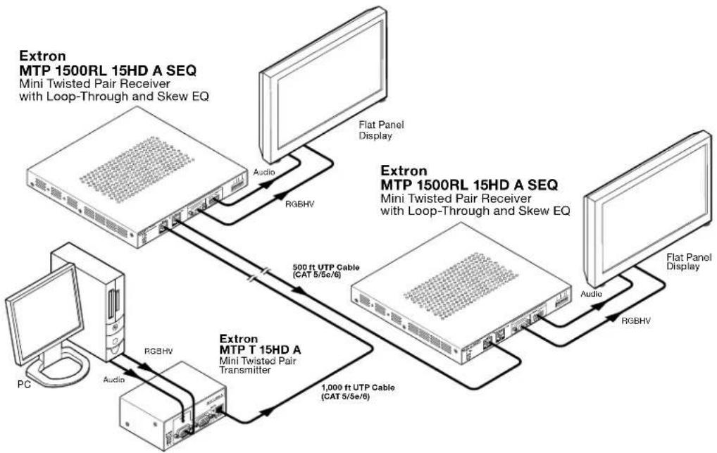
flowchart
graph TD
    PC["PC"] -->|Audio| Transmitter["Extron MTP T 15HD A Mini Twisted Pair Transmitter"]
    Transmitter -->|RGBHV| ExtronMTP1["Extron MTP 1500RL 15HD A SEQ Mini Twisted Pair Receiver with Loop-Through and Skew EQ"]
    ExtronMTP1 -->|RGBHV| ExtronMTP2["Extron MTP 1500RL 15HD A SEQ Mini Twisted Pair Receiver with Loop-Through and Skew EQ"]
    ExtronMTP2 -->|RGBHV| ExtronMTP3["Extron MTP 1500RL 15HD A SEQ Mini Twisted Pair Receiver with Loop-Through and Skew EQ"]
    ExtronMTP3 -->|RGBHV| ExtronMTP4["Extron MTP 1500RL 15HD A SEQ Mini Twisted Pair Receiver with Loop-Through and Skew EQ"]
    ExtronMTP4 -->|RGBHV| ExtronMTP5["Extron MTP 1500RL 15HD A SEQ Mini Twisted Pair Receiver with Loop-Through and Skew EQ"]
    ExtronMTP5 -->|RGBHV| ExtronMTP6["Extron MTP 1500RL 15HD A SEQ Mini Twisted Pair Receiver with Loop-Through and Skew EQ"]
    ExtronMTP6 -->|RGBHV| ExtronMTP7["Extron MTP 1500RL 15HD A SEQ Mini Twisted Pair Receiver with Loop-Through and Skew EQ"]
    ExtronMTP7 -->|RGBHV| ExtronMTP8["Extron MTP 1500RL 15HD A SEQ Mini Twisted Pair Receiver with Loop-Through and Skew EQ"]
    ExtronMTP8 -->|RGBHV| ExtronMTP9["Extron MTP 1500RL 15HD A SEQ Mini Twisted Pair Receiver with Loop-Through and Skew EQ"]
    ExtronMTP9 -->|RGBHV| ExtronMTP10["Extron MTP 1500RL 15HD A SEQ Mini Twisted Pair Receiver with Loop-Through and Skew EQ"]
    ExtronMTP10 -->|RGBHV| ExtronMTP11["Extron MTP 1500RL 15HD A SEQ Mini Twisted Pair Receiver with Loop-Through and Skew EQ"]
    ExtronMTP11 -->|RGBHV| ExtronMTP12["Extron MTP 1500RL 15HD A SEQ Mini Twisted Pair Receiver with Loop-Through and Skew EQ"]
    ExtronMTP12 -->|RGBHV| ExtronMTP13["Extron MTP 1500RL 15HD A SEQ Mini Twisted Pair Receiver with Loop-Through and Skew EQ"]
    ExtronMTP13 -->|RGBHV| ExtronMTP14["Extron MTP 1500RL 15HD A SEQ Mini Twisted Pair Receiver with Loop-Through and Skew EQ"]
    ExtronMTP14 -->|RGBHV| ExtronMTP15["Extron MTP 1500RL 15HD A SEQ Mini Twisted Pair Receiver with Loop-Through and Skew EQ"]
    ExtronMTP15 -->|RGBHV| ExtronMTP16["Extron MTP 1500RL 15HD A SEQ Mini Twisted Pair Receiver with Loop-Through and Skew EQ"]
    ExtronMTP16 -->|RGBHV| ExtronMTP17["Extron MTP 1500RL 15HD A SEQ Mini Twisted Pair Receiver with Loop-Through and Skew EQ"]
    ExtronMTP17 -->|RGBHV| ExtronMTP18["Extron MTP 1500RL 15HD A SEQ Mini Twisted Pair Receiver with Loop-Through and Skew EQ"]
    ExtronMTP18 -->|RGBHV| ExtronMTP19["Extron MTP 1500RL 15HD A SEQ Mini Twisted Pair Receiver with Loop-Through and Skew EQ"]
    ExtronMTP19 -->|RGBHV| ExtronMTP20["Extron MTP 1500RL 15HD A SEQ Mini Twisted Pair Receiver with Loop-Through and Skew EQ"]
    ExtronMTP20 -->|RGBHV| ExtronMTP21["Extron MTP 1500RL 15HD A SEQ Mini Twisted Pair Receiver with Loop-Through and Skew EQ"]
    ExtronMTP21 -->|RGBHV| ExtronMTP22["Extron MTP 1500RL 15HD A SEQ Mini Twisted Pair Receiver with Loop-Through and Skew EQ"]
    ExtronMTP22 -->|RGBHV| ExtronMTP23["Extron MTP 1500RL 15HD A SEQ Mini Twisted Pair Receiver with Loop-Through and Skew EQ"]
    ExtronMTP23 -->|RGBHV| ExtronMTP24["Extron MTP 1500RL 15HD A SEQ Mini Twisted Pair Receiver with Loop-Through and Skew EQ"]
    ExtronMTP24 -->|RGBHV| ExtronMTP25["Extron MTP 1500RL 15HD A SEQ Mini Twisted Pair Receiver with Loop-Through and Skew EQ"]
    ExtronMTP25 -->|RGBHV| ExtronMTP26["Extron MTP 1500RL 15HD A SEQ Mini Twisted Pair Receiver with Loop-Through and Skew EQ"]
    ExtronMTP26 -->|RGBHV| ExtronMTP27["Extron MTP 1500RL 15HD A SEQ Mini Twisted Pair Receiver with Loop-Through and Skew EQ"]
    ExtronMTP27 -->|RGBHV| ExtronMTP28["Extron MTP 1500RL 15HD A SEQ Mini Twisted Pair Receiver with Loop-Through and Skew EQ"]
    ExtronMTP28 -->|RGBHV| ExtronMTP29["Extron MTP 1500RL 15HD A SEQ Mini Twisted Pair Receiver with Loop-Through and Skew EQ"]
    ExtronMTP29 -->|RGBHV| ExtronMTP30["Extron MTP 1500RL 15HD A SEQ Mini Twisted Pair Receiver with Loop-Through and Skew EQ"]
    ExtronMTP30 -->|RGBHV| ExtronMTP31["Extron MTP 1500RL 15HD A SEQ Mini Twisted Pair Receiver with Loop-Through and Skew EQ"]
    ExtronMTP31 -->|RGBHV| ExtronMTP32["Extron MTP 1500RL 15HD A SEQ Mini Twisted Pair Receiver with Loop-Through and Skew EQ"]
    ExtronMTP32 -->|RGBHV| ExtronMTP33["Extron MTP 1500RL 15HD A SEQ Mini Twisted Pair Receiver with Loop-Through and Skew EQ"]
    ExtronMTP33 -->|RGBHV| ExtronMTP34["Extron MTP 1500RL 15HD A SEQ Mini Twisted Pair Receiver with Loop-Through and Skew EQ"]
    ExtronMTP34 -->|RGBHV| ExtronMTP35["Extron MTP 1500RL 15HD A SEQ Mini Twisted Pair Receiver with Loop-Through and Skew EQ"]
    ExtronMTP35 -->|RGBHV| ExtronMTP36["Extron MTP 1500RL 15HD A SEQ Mini Twisted Pair Receiver with Loop-Through and Skew EQ"]
    ExtronMTP36 -->|RGBHV| ExtronMTP37["Extron MTP 1500RL 15HD A SEQ Mini Twisted Pair Receiver with Loop-Through and Skew EQ"]
    ExtronMTP37 -->|RGBHV| ExtronMTP38["Extron MTP 1500RL 15HD A SEQ Mini Twisted Pair Receiver with Loop-Through and Skew EQ"]
    ExtronMTP38 -->|RGBHV| ExtronMTP39["Extron MTP 1500RL 15HD A SEQ Mini Twisted Pair Receiver with Loop-Through and Skew EQ"]
    ExtronMTP39 -->|RGBHV| ExtronMTP40["Extron MTP 1500RL 15HD A SEQ Mini Twisted Pair Receiver with Loop-Through and Skew EQ"]
    ExtronMTP40 -->|RGBHV| ExtronMTP41["Extron MTP 1500RL 15HD A SEQ Mini Twisted Pair Receiver with Loop-Through and Skew EQ"]
    ExtronMTP41 -->|RGBHV| ExtronMTP42["Extron MTP 1500RL 15HD A SEQ Mini Twisted Pair Receiver with Loop-Through and Skew EQ"]
    ExtronMTP42 -->|RGBHV| ExtronMTP43["Extron MTP 1500RL 15HD A SEQ Mini Twisted Pair Receiver with Loop-Through and Skew EQ"]
    ExtronMTP43 -->|RGBHV| ExtronMTP44["Extron MTP 1500RL 15HD A SEQ Mini Twisted Pair Receiver with Loop-Through and Skew EQ"]
    ExtronMTP44 -->|RGBHV| ExtronMTP45["Extron MTP 1500RL 15HD A SEQ Mini Twisted Pair Receiver with Loop-Through and Skew EQ"]
    ExtronMTP45 -->|RGBHV| ExtronMTP46["Extron MTP 1500RL 15HD A SEQ Mini Twisted Pair Receiver with Loop-Through and Skew EQ"]
    ExtronMTP46 -->|RGBHV| ExtronMTP47["Extron MTP 1500RL 15HD A SEQ Mini Twisted Pair Receiver with Loop-Through and Skew EQ"]
    ExtronMTP47 -->|RGBHV| ExtronMTP48["Extron MTP 1500RL 15HD A SEQ Mini Twisted Pair Receiver with Loop-Through and Skew EQ"]
    ExtronMTP48 -->|RGBHV| ExtronMTP49["Extron MTP 1500RL 15HD A SEQ Mini Twisted Pair Receiver with Loop-Through and Skew EQ"]
    ExtronMTP49 -->|RGBHV| ExtronMTP50["Extron MTP 1500RL 15HD A SEQ Mini Twisted Pair Receiver with Loop-Through and Skew EQ"]
    ExtronMTP50 -->|RGBHV| ExtronMTP51["Extron MTP 1500RL 15HD A SEQ Mini Twisted Pair Receiver with Loop-Through and Skew EQ"]
    ExtronMTP51 -->|RGBHV| ExtronMTP52["Extron MTP 1500RL 15HD A SEQ Mini Twisted Pair Receiver with Loop-Through and Skew EQ"]
    ExtronMTP52 -->|RGBHV| ExtronMTP53["Extron MTP 1500RL 15HD A SEQ Mini Twisted Pair Receiver with Loop-Through and Skew EQ"]
    ExtronMTP53 -->|RGBHV| ExtronMTP54["Extron MTP 1500RL 15HD A SEQ Mini Twisted Pair Receiver with Loop-Through and Skew EQ"]
    ExtronMTP54 -->|RGBHV| ExtronMTP55["Extron MTP 1500RL 15HD A SEQ Mini Twisted Pair Receiver with Loop-Through and Skew EQ"]
    ExtronMTP55 -->|RGBHV| ExtronMTP56["Extron MTP 1500RL 15HD A SEQ Mini Twisted Pair Receiver with Loop-Through and Skew EQ"]
    ExtronMTP56 -->|RGBHV| ExtronMTP57["Extron MTP 1500RL 15HD A SEQ Mini Twisted Pair Receiver with Loop-Through and Skew EQ"]
    ExtronMTP57 -->|RGBHV| ExtronMTP58["Extron MTP 1500RL 15HD A SEQ Mini Twisted Pair Receiver with Loop-Through and Skew EQ"]
    ExtronMTP58 -->|RGBHV| ExtronMTP59["Extron MTP 1500RL 15HD A SEQ Mini Twisted Pair Receiver with Loop-Through and Skew EQ"]
    ExtranLPC["ExtranLPC"] --> RGBHVS
Figure 1. Typical MTP 1500RL 15HD A SEQ Application
Installation
Mounting instructions can be found in Mounting the Receiver on page 10. Compatible optional hardware is listed on the Extron website (www.extron.com).
Connections and Settings
Figure 2 shows the MTP 1500RL A rear panel. The SEQ receiver is identical.

Figure 2. Receiver Rear Panel Features
Power connector — Plug the included external 12 VDC, 1 A, power supply into this 2-pole captive screw connector. See Power Supply Wiring on page 5 to wire the connector.
B Signal input connector — Connect one end of the twisted pair (TP) cable from an MTP transmitter. See TP Cable Termination on page 6 to wire the connectors.
ATTENTION:
NOTE: Minimum distance from the transmitter is 50 feet.
Buffered output connector — Connect up to 8 daisy-chained MTP receivers to this RJ-45 connector.
NOTE: In a daisy chain, the maximum distance from video source to display device should not exceed 1500 feet.
High resolution video output connector — Connect a projector or other high resolution video device to this 15-pin HD connector for RGB output.
NOTE: See DIP switch settings for signal format output.
E Audio connector — Connect a suitable audio device to the 5-pole captive screw connector for mono audio output.
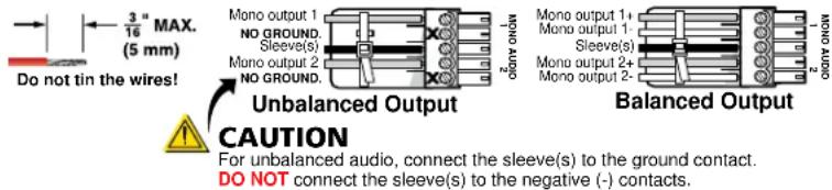
Figure 3. Audio Connector Wiring
F Receiver DIP switches — Set these DIP switches for the applicable signal.
- H sync (H+) and V sync (V+) switches — Set these switches up (on) for positive sync or down for negative sync.
- Composite sync (CSync), Sync on green (SOG), and Video switches — Set these switches as shown in the table below to output the indicated format.
| Output Format C Sync SOG Video | |||
| RGBHV Down Down | Up | ||
| RGBS Up Down | Down | ||
| RGsB | Down Up | Down | |
| Component video* | Down Down Up | ||
| S-video | Down Down Up | ||
| Composite video* | Down Down | ||
* Input video format must match.
• End unit switch — Set this switch up if either of the following is true:
- The receiver being configured is the only receiver connected to the transmitter.
- The receiver being configured is the last receiver in a daisy-chained system.
Power Supply Wiring
Figure 4 shows how to wire the connector. Insert the wired plug into the power connector on the rear panel. Do not power on the device at this time.
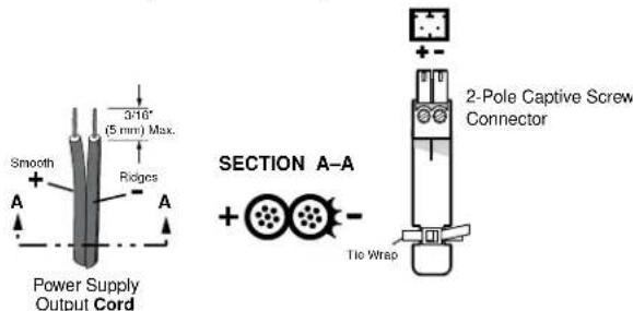
Figure 4. Power Connector Wiring
CAUTION:
ATTENTION :
- The wires must be kept separate while the power supply is plugged in. Remove power before wiring.
- Les deux cordons d'alimentation doivent être maintenus séparés lorsque la source d'alimentation est branchée. Coupez l'alimentation avant d'effectuer un raccordement.
-
The length of exposed wires is important. The ideal length is 3/16 inch (5 mm).
-
Any longer and the exposed wires may touch, causing a short circuit between them.
- Any shorter and the wires can be easily pulled out even if tightly fastened by the captive screws.
To verify the polarity before connection, plug in the power supply with no load and check the output with a voltmeter.
As an alternative, an Extron PS 124 Multiple Output 12 Volt DC Power Supply can power multiple MTPs or other Extron 12 VDC devices using only one AC power connector.
TP Cable Termination
ATTENTION:
NOTE: RJ-45 termination must comply with TIA/EIA T568A or TIA/EIA T568B wiring standards for all connections.
Figure 5 details the TIA/EIA-T568B or TIA/EIA T568B wiring standards. Use this standard to terminate the DTP cable with RJ-45 connectors.
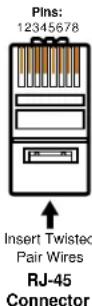
| Pin | T568A T568B Wire color | Wire color |
| 1 | White-green | White-orange |
| 2 | Green | Orange |
| 3 | White-orange | White-green |
| 4 | Blue | Blue |
| 5 | White-blue | White-blue |
| 6 | Orange | Green |
| 7 | White-brown | White-brown |
| 8 | Brown | Brown |
Figure 5. TP Cable Termination
NOTES:
- If you are using Enhanced Skew-Free A/V cable, use the TIA/EIA T568A standard only.
- Enhanced Skew-free A/V cable is not recommended for Ethernet/LAN applications.
- This cable is specially designed for compatibility with Extron Twisted Pair products that are wired using the TIA/EIA T568A standard.
The table below shows the MTP RJ-45 pin assignments for audio and video signals.
| Pin | RGBHV RGBS | Composite S-Video Component | |||
| 1 | Red/V sync + Red | + No Signal Chroma + R-Y + | |||
| 2 | Red/V sync - Red | - No Signal Chroma - | R-Y - | ||
| 3 | Mono Audio+ | Mono Audio + | Mono Audio + | Mono Audio + | Mono Audio + |
| 4 | Green + | Green + | Video + | Luma + | Y + |
| 5 | Green - | Green - | Video - | Luma - | Y - |
| 6 | Mono Audio - | Mono Audio - | Mono Audio - | Mono Audio - | Mono Audio - |
| 7 | Blue/H Sync + | Blue/C Sync + | No Signal | No Signal | B-Y + |
| 8 | Blue/H Sync - | Blue/C Sync - | No Signal | No Signal | B- Y - |
Front Panel Controls and Indicators
Figure 6 shows the front panel features on the MTP 1500RL 15HD A SEQ. The MTP 1500RL 15HD A is similar but without the Delay controls (items D through F) on the next page.

Figure 6. MTP receiver series front panels
Power LED — Indicates power is applied to the receiver.
B Level control — Alters the video output voltage to affect the brightness of the displayed image. Adjust the knob while viewing the displayed image to set the level and boost that provides the best picture quality. See Peaking and Level Adjustment on the next page for details.
Peaking control — Affects the sharpness of a picture. Increased peaking can compensate for mid- and high-frequency detail loss from low bandwidth system components or capacitance in long cables.
Adjust this control while viewing the displayed image to obtain the optimum picture sharpness. The LED lights red when at the minimum (zero) and maximum (100%) peaking settings. See Peaking and Level Adjustment for details.
NOTE: To avoid possible video loss due to errors in the format detection, the user should always start with minimal peaking and level, then only increase values as required.
D Select button (SEQ receiver only, see the previous page) — This recessed button selects the red, green, or blue video signal to adjust and resets all three video signals to a skew delay of zero nanoseconds.
Use a Tweeker to press and release this button to cycle and select the red, green, or blue video signal to adjust. The selected signal is indicated by the Red, Green, and Blue LEDs (E).
NOTE: The SEQ receiver automatically saves the setting for the video signal that is being deselected when this button is pushed or when the selection times out after 10 seconds.
Press and hold the button in for approximately 3 seconds to zero the skew delay for red, green, and blue. The Red, Green, and Blue LEDS (E) all turn off. Release the button.
E R(ed), G(reen), and B(lue) LEDs (SEQ receiver only) — These indicate the video signal that is selected by the Select button (b) for skew adjustment using the Adjust control (F). The LED for the selected color flashes when the skew compensation for that color's video signal has reached the minimum or maximum limit.
F Adjust skew control (SEQ receiver only) — This control delays the selected red, green, or blue video signal by up to a maximum of 62 nanoseconds (ns), in 2 ns incremental steps. Rotate the control counterclockwise to reduce the delay or clockwise to increase the delay. See Skew Delay Compensation on the next page for details.
NOTE: The movement of the Adjust control is smooth; it does not have mechanical steps or high- and low-limit stops.
Watch the displayed image to observe the steps of delay.
For best performance the skew of the most delayed signal should be set to 0 ns (min.) and the other two signals adjusted to meet it.
Peaking and Level Adjustment
For best performance and video format detection, the equalization of the MTP receiver should be adjusted properly.
To achieve this do the following:
- Terminate the green video signal output with a 75 ohm resistance, and measure the video signal.
NOTE: Gain adjustment should be set so that a white field video signal is +0.7 volts from the ground level.
Peaking adjustment should be set using the highest frequency video format signal for the system in RGB, component video, or S-video.
- Using an alternative black/white pattern, adjust the peaking so that the video signal matches that of the white field video. This equalizes both the low frequency (white field) and the high frequency (alternating black/white field) to the same video level for best results. Do not over-peak the signal.
Skew Delay Compensation
CAT cable can lead to registration errors between the red, green, and blue video signals. Pair skew can be measured with test equipment or identified by viewing a crosshatch test pattern with a critical eye to determine if either the red, green, or blue video image leads (appears to the left of) the other two video images.
NOTE: Unless the TP cable is changed, the skew adjustment should only need to be made once, during installation..
SEQ receiver skew compensation
The SEQ receiver has built-in skew compensation capabilities. Adjust the equalization as follows:
- Zero the skew delay for red, green, and blue as follows:
a. Use a Tweeker or other small screwdriver to press and hold the Select button for 3 seconds. The Red, Green, and Blue LEDS all go out.
b. Release the Select button.
- Use UTP cable test equipment or examine the displayed video image with a critical eye to determine which video signal, red, green, or blue, is shifted furthest to the right.
NOTE: A crosshatch test pattern or a black background with vertical white lines is ideal for determining skew.
- Adjust the furthest left video signal as follows:
NOTE: The SEQ receiver cannot shift the furthest right video image to the left.
a. Use a Tweeker or other small screwdriver to press and release the Select button until the LED for the left-shifted color (Red, Green, or Blue) lights.
b. Slowly rotate the Adjust control clockwise while monitoring the display. Continue to rotate the control until that color is properly converged.
NOTE: A 2-nanosecond (ns) adjustment is very fine. Up to 10 ns of delay may be necessary before a change in the display is detectable. Maximum delay possible is 62 nanoseconds.
c. Use a Tweeker or other small screwdriver to press the Select button one more time to save the most recent adjustment or allow the 10-second timeout to elapse.
- If the remaining color is left shifted, repeat step 3.
Non-SEQ receivers skew compensation
Try using the following methods to minimize or eliminate pair skew:
- Switch to Extron Enhanced Skew-Free A/V UTP cable.
- Add a skew compensation cable equal to the length of pair skew to the receiver's output.
- Install an Extron SEQ 100 15HD Skew Equalizer on the video output of the receiver and adjust the skew for the leading video image.
Mounting the Receiver
ATTENTION:
The 1-inch high, half rack width receiver can be placed on a table, mounted in a rack, or mounted under a desk or table.
Tabletop Use
Affix the included rubber feet to the bottom of the unit and place it in any convenient location.
Mounting kits
Mount the unit using any optional compatible mounting kit listed on the Extron website (www.extron.com), in accordance with the directions included with the kit. For rack mounting, see "UL Rack-Mounting Guidelines".
UL Rack-Mounting Guidelines
The following Underwriters Laboratories (UL) requirements pertain to the installation of the unit into a rack.
- Elevated operating ambient temperature — If installed in a closed or multi-unit rack assembly, the operating ambient temperature of the rack environment may be greater than room ambient. Therefore, consider installing the equipment in an environment compatible with the maximum ambient temperature (TMA = +122 °F, +50 °C) specified by Extron.
- Reduced air flow — Installation of the equipment in a rack should be such that the amount of air flow required for safe operation of the equipment is not compromised.
- Mechanical loading — Mounting of the equipment in the rack should be such that a hazardous condition is not achieved due to uneven mechanical loading.
- Circuit overloading — Consideration should be given to the connection of the equipment to the supply circuit and the effect that overloading of the circuits might have on overcurrent protection and supply wiring. Appropriate consideration of equipment nameplate ratings should be used when addressing this concern.
- Reliable earthing (grounding) — Reliable earthing of rack-mounted equipment should be maintained. Particular attention should be given to supply connections other than direct connections to the branch circuit (such as use of power strips).
Extron Warranty
Extron Electronics warrants this product against defects in materials and workmanship for a period of three years from the date of purchase. In the event of malfunction during the warranty period attributable directly to faulty workmanship and/or materials, Extron Electronics will, at its option, repair or replace said products or components, to whatever extent it shall deem necessary to restore said product to proper operating condition, provided that it is returned within the warranty period, with proof of purchase and description of malfunction to:
USA, Canada, South America, and Central America:
Extron Electronics
1230 South Lewis Street
Anaheim, CA 92805
U.S.A.
Japan:
Extron Electronics, Japan
Kyodo Building, 16 Ichibancho
Chiyoda-ku, Tokyo 102-0082
Japan
Europe and Africa:
Extron Europe
Hanzeboulevard 10
3825 PH Amersfoort
The Netherlands
China:
Extron China
686 Ronghua Road
Songjiang District
Shanghai 201611
China
Asia:
Extron Asia Pte Ltd
135 Joo Seng Road, #04-01
PM Industrial Bldg.
Singapore 368363
Singapore
Middle East:
Extron Middle East
Dubai Airport Free Zone
F13, PO Box 293666
United Arab Emirates, Dubai
This Limited Warranty does not apply if the fault has been caused by misuse, improper handling care, electrical or mechanical abuse, abnormal operating conditions, or if modifications were made to the product that were not authorized by Extron.
NOTE: If a product is defective, please call Extron and ask for an Application Engineer to receive an RA (Return Authorization) number. This will begin the repair process.
USA: 714.491.1500 or 800.633.9876
Europe: 31.33.453.4040
Asia: 65.6383.4400
Japan: 81.3.3511.7655
Units must be returned insured, with shipping charges prepaid. If not insured, you assume the risk of loss or damage during shipment. Returned units must include the serial number and a description of the problem, as well as the name of the person to contact in case there are any questions.
Extron Electronics makes no further warranties either expressed or implied with respect to the product and its quality, performance, merchantability, or fitness for any particular use. In no event will Extron Electronics be liable for direct, indirect, or consequential damages resulting from any defect in this product even if Extron Electronics has been advised of such damage.
Please note that laws vary from state to state and country to country, and that some provisions of this warranty may not apply to you.
| Extron Headquarters+1.800.633.9876 (Inside USA/Canada Only)Extron USA - West Extron USA - East+1.714.491.1500 +1.919.850.1000+1.714.491.1517 FAX +1.919.850.1001 FAX | Extron Europe+800.3987.6673(Inside Europe Only)+31.33.453.4040+31.33.453.4050 FAX | Extron Asia+65.6383.4400+65.6383.4664 FAX | Extron Japan+81.3.3511.7665+81.3.3511.7656 FAX | Extron China+86.21.3760.1568+86.21.3760.1566 FAX | Extron Middle East+971.4.299.1800+871.4.299.1800 FAX | Extron Australia+61.8.8113.6800+61.8.8351.2511 FAX | Extron India1800.3070.3777(Inside India Only)+91.80.3055.3777+91.80.3055.3737 FAX |
- MTP 1500RL 15HD A and MTP 1500RL 15HD A SEQ
- Safety Instructions
- Safety Instructions • English
- Trademarks
- FCC Class A Notice
- NOTES:
- Conventions Used in this Guide
- Notifications
- Specifications Availability
- Extron Glossary of Terms
- Contents
- MTP 1500RL 15HD A Series....1
- MTP 1500RL 15HD A Series
- About this Guide
- About the MTP 1500RL 15HD A Series Receivers
- TP Cable Advantages
- Transmission Distance
- Application Diagram
- Installation
- Connections and Settings
- ATTENTION:
- Power Supply Wiring
- CAUTION:
- ATTENTION :
- TP Cable Termination
- Front Panel Controls and Indicators
- Peaking and Level Adjustment
- Skew Delay Compensation
- SEQ receiver skew compensation
- Non-SEQ receivers skew compensation
- Mounting the Receiver
- Tabletop Use
- Mounting kits
- UL Rack-Mounting Guidelines
- Extron Warranty
- USA, Canada, South America, and Central America:
- Japan:
- Europe and Africa:
- China:
- Asia:
- Middle East:
Brand : Extron
Model : MTP 1500RL 15HD A SEQ
Category : Audiovisual Equipment