
DTP DVI 330 Rx - Audiovisual Equipment Extron - Free user manual and instructions
Find the device manual for free DTP DVI 330 Rx Extron in PDF.


| Product Type | DVI Twisted Pair Receiver |
| Model | DTP DVI 330 Rx |
| Brand | Extron |
| Dimensions (H x W x D) | 1 inch x 5.2 inches x 3 inches (approx.) |
| Weight | 0.5 kg (approx.) |
| Power Supply | External 12 VDC, 1.0 A minimum, Class 2 or LPS |
| Power Consumption | Less than 10 W (typical) |
| Video Input | DVI (single link) via RJ-45 (DTP In) |
| Video Output | DVI (single link) on DVI-I connector |
| Max Transmission Distance | 330 feet (100 m) over CATx cable |
| Supported Cable Types | CAT 5e, 6, 6a, 7 STP or UTP; recommended XTP DTP 24 |
| Audio Support | Analog audio pass-through (unbalanced stereo) |
| Control Pass-Through | Bidirectional RS-232 and IR |
| DDC Support | Yes, with DDC Route switch for EDID |
| Remote Powering | Yes, both units can be powered from one supply via DTP cable |
| Mounting Options | Tabletop, rack mount (optional kit), under-desk, projector bracket |
| Enclosure | Metal, quarter rack width, 1U high |
| LED Indicators | Power (amber/green), Signal (green), Link (green) |
| Operating Temperature | 32°F to 122°F (0°C to 50°C) |
| Storage Temperature | -4°F to 158°F (-20°C to 70°C) |
| Warranty | 3 years |
Frequently Asked Questions - DTP DVI 330 Rx Extron
User questions about DTP DVI 330 Rx Extron
0 question about this device. Answer the ones you know or ask your own.
Ask a new question about this device
Download the instructions for your Audiovisual Equipment in PDF format for free! Find your manual DTP DVI 330 Rx - Extron and take your electronic device back in hand. On this page are published all the documents necessary for the use of your device. DTP DVI 330 Rx by Extron.
USER MANUAL DTP DVI 330 Rx Extron
Safety Instructions • English
WARNING: This symbol, A, when used on the product, is intended to alert the user of the presence of uninsulated dangerous voltage within the product's enclosure that may present a risk of electric shock.
ATTENTION: This symbol, △ when used on the product, is intended to alert the user of important operating and maintenance (servicing) instructions in the literature provided with the equipment.
For information on safety guidelines, regulatory compliances, EMI/EMF compatibility, accessibility, and related topics, see the Extron Safety and Regulatory Compliance Guide, part number 68-290-01, on the Extron website, www.extron.com.
Chinese Traditional (繁體中文)
This equipment has been tested and found to comply with the limits for a Class A digital device, pursuant to part 15 of the FCC rules. The Class A limits provide reasonable protection against harmful interference when the equipment is operated in a commercial environment. This equipment generates, uses, and can radiate radio frequency energy and, if not installed and used in accordance with the instruction manual, may cause harmful interference to radio communications. Operation of this equipment in a residential area is likely to cause interference; correcting the interference is at the expense of the user.
ATTENTION: The Twisted Pair Extension technology works with unshielded twisted pair (UTP) or shielded twisted pair (STP) cables; but, to ensure FCC Class A and CE compliance, STP cables and STP Connectors are required.
For more information on safety guidelines, regulatory compliances, EMI/EMF compatibility, accessibility, and related topics, see the "Extron Safety and Regulatory Compliance Guide" on the Extron website.
Specifications Availability
Product specification are available on the Extron website, www.extron.com.
Conventions Used in this Guide
Notifications
The following notifications are used in this guide:
CAUTION: A caution indicates a situation that may result in minor injury.
ATTENTION: Attention indicates a situation that may damage or destroy the product or associated equipment.
NOTE: A note draws attention to important information.
Copyright
© 2013 Extron Electronics. All rights reserved.
Trademarks
All trademarks mentioned in this guide are the properties of their respective owners.
The following registered trademarks ^® , registered service marks ^(SM) , and trademarks ^(TM) are the property of RGB Systems, Inc. or Extron Electronics:
| Registered Trademarks ^(8) |
| AVTrac, Cable Cubby, CrossPoint, eBUS, EDID Manager, EDID Minder, Extron, Flat Field, GlobalViewer, Hideaway, Inline, IP Intercom, IP Link, Key Minder, LockIt, MediaLink, PoleVault, PowerCage, PURE3, Quantum, SoundField, SpeedMount, SpeedSwitch, System Integrator, TeamWork, TouchLink, V-Lock, VersaTools, VN-Matrix, VoiceLift, WallVault, WindoWall |
| Registered Service Mark ^(SM) : S3 Service Support Solutions |
| Trademarks ^(TM) |
| AAP, AFL (Accu-Rate Frame Lock), ADSP (Advanced Digital Sync Processing), AIS (Advanced Instruction Set), Auto-Image, CDRS (Class D Ripple Suppression), DDSP (Digital Display Sync Processing), DMI (Dynamic Motion Interpolation), Driver Configurator, DSP Configurator, DSVP (Digital Sync Validation Processing), FastBite, FOXBOX, IP Intercom HelpDesk, MAAP, MicroDigital, ProDSP, QS-FPC (QuickSwitch Front Panel Controller), Scope-Trigger, SIS, Simple Instruction Set, Skew-Free, SpeedNav, Triple-Action Switching, XTP, XTP Systems, XTRA, ZipCaddy, ZipClip |
Contents
Introduction.... 1
About this Guide....1
About the DTP DVI 330 Tx/Rx Transmitter and Receiver....1
TP Cable Advantages....2
Control Communications 2
Features 2
Installation and Operation....3
Mounting the Units 3
Connections....3
Transmitter Connections 3
Receiver Connections....5
Connector and Cable Details 6
Operation 9
Reference Information 10
Mounting the Transmitter or Receiver....10
Tabletop Use 10
Mounting kits....10
UL Rack-Mounting Guidelines 11
Disconnecting the Ground....11
Introduction
• About this Guide
• About the DTP DVI 330 Transmitter and Receiver
- Features
About this Guide
This guide describes the Extron DTP DVI 330 Long Distance Digital Visual Interface (DVI) Twisted Pair Extender, which consists of a DTP DVI 330 Tx transmitter and a DTP DVI 330 Rx receiver. This guide describes how to install, operate, and configure the transmitter and receiver.
About the DTP DVI 330 Tx/Rx Transmitter and Receiver
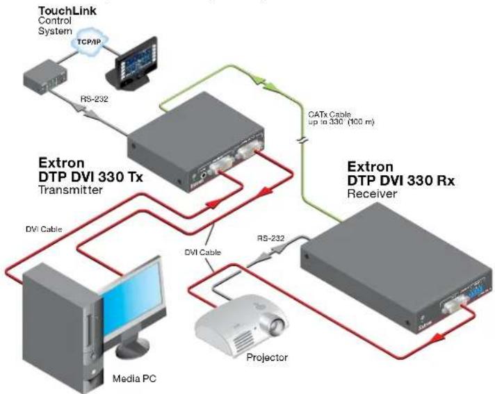
The Extron DTP DVI 330 Tx/Rx transmitter and receiver pair (see figure 1) extends the usable distance of DVI digital video, optional analog audio, and bidirectional RS-232 and infrared (IR) control signals over one Extron XTP DTP 24 shielded twisted pair (STP) cable (recommended) or Category (CAT) 5e, CAT 6, or CAT 6a STP or unshielded twisted pair (UTP) cable. The DTP DVI 330 can also extend HDMI video, which may include embedded audio, with the appropriate adapters. The video, audio, and control signals can be transmitted up to 330 feet (100 m).
flowchart
graph TD
    A["TouchLink Control System"] -->|TCP/IP| B["Extron DTP DVI 330 Tx Transmitter"]
    B -->|RS-232| C["Extron DTP DVI 330 Rx Receiver"]
    C -->|CATx Cable up to 330 (100 m)| B
    B -->|DVI Cable| D["Media PC"]
    C -->|RS-232| E["Projector"]
    B -->|DVI Cable| F["Extron DTP DVI 330 Tx Transmitter"]
Figure 1. Typical Transmitter and Receiver Application
The DTP DVI 330 Tx/Rx units are housed in quarter rack width metal enclosures. They can be set on a tabletop or mounted in a rack, under or through furniture. The receiver can also be mounted on a projector bracket.
The transmitter is shipped with a single external desktop 12 VDC power supply that accepts 100 to 240 VAC, 50-60 Hz input. A single power supply connected to either the transmitter or the receiver can power both units through the TP cable that carries DVI video.
TP Cable Advantages
Twisted pair cable is much smaller, lighter, more flexible, and less expensive than coaxial or DVI cable. These transmitter and receiver twisted pair (TP) products make cable runs simpler and less cumbersome. Termination of the cable with RJ-45 connectors is simple, quick, and economical.
NOTE: Do not use Extron UTP23SF-4 Enhanced Skew-Free AV UTP cable or STP201 cable to link the transmitter and receiver. The DTP DVI 330 Tx/Rx does not work properly with these cables.
Control Communications
The RS-232 and IR communications are a passive pass-through only. The transmitter and receiver do not generate or respond to the RS-232 and IR communication signals.
Features
Transmits single link DVI signals over a single STP or UTP cable — Standard twisted pair cables provide an economical, easily installed cable solution.
Long distance transmission — Extends video, audio, and control signals up to 330 feet (100 m).
Supports Display Data Channel (DDC) transmission — The transmitter and receiver pair fully supports long distance transmission of the DDC signals.
Control communications pass-through — Bidirectional RS-232 and IR control signals can be transmitted alongside the DVI signal, so that the remote display can be controlled without the need for additional cabling.
Supports Consumer Electronics Control (CEC) signal transmission
1-inch high, quarter rack width, metal enclosures — With low profile enclosures, the transmitter and receiver can be discreetly installed in locations such as behind a plasma or LCD flat-panel display.
External 100 VAC to 240 VAC, 50-60 Hz, international power supply — One power supply is included with the transmitter.
Remote powering of transmitter or receiver — Only one power supply is normally necessary to power both devices.
Installation and Operation
This section describes the installation and the operation of the DTP DVI 330 Tx/Rx Extender, including:
- Mounting the Units
- Connections
Operation
Mounting the Units
Mounting instructions can be found in Mounting the Transmitter or Receiver on page 10. Compatible optional hardware is listed on the Extron website (www.extron.com).
ATTENTION:
• Installation and service must be performed by authorized personnel only.
- Avoid ground potential differences between the transmitter and receiver installation sites, which can lead to equipment damage or a missing or unstable picture. If a potential difference cannot be avoided, remove the ground connection between the units and locally power both units (see Disconnecting the Ground on page 11). In this configuration, the DTP DVI 330 cannot extend analog audio and each unit requires a local power supply.
Connections
Transmitter Connections

Figure 2. DTP DVI 330 Tx Connectors
① DVI input connector — Connect an DVI cable between this port and the DVI output port (or HDMI port, with an appropriate adapter) of the digital video source.
② Local Output connector — If desired, connect a DVI monitor for local monitoring of the input digital image.
NOTES:
• The local output is limited to a data rate of 4.95 Gbps (1.65 Gbps per color).
- In a system where the local output is not used, ensure that you power up the end display first before the video source. Route the DDC to the remote end (see the DDC Route DIP switch [see item ③ on page 9]).
③ Audio input connector — If desired, plug an analog audio input into the transmitter via this stereo mini jack connector.
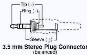
NOTE: The analog audio input on this connector is in addition to the digital audio that may be embedded in the DVI input. See the figure at right to identify the connector tip, ring, and sleeve when you are making connections for the transmitter from existing audio cables. A mono audio connector consists of the tip and sleeve. A stereo audio connector consists of the tip, ring, and sleeve.
④ RS-232 and IR connector — Connect a serial RS-232 signal, a modulated IR signal, or both to this 3.5 mm, 5-pole captive screw connector for bidirectional RS-232 and IR communication (see RS-232 and IR connector wiring on page 9 to wire the connector).
⑤ DTP Output RJ-45 connector — Connect one end of a TP cable to this RJ-45 female connector on the transmitter. Ensure the opposite end of this cable is connected to the receiver DTP Input RJ-45 connector (see item ⑦ on the next page).
ATTENTION: Do not connect this device to a telecommunications or computer data network.
NOTE: See TP cable termination and recommendations on page 6 to properly wire the RJ-45 connectors and for detailed NOTES.
Signal LED — Indicates the unit is receiving a TMDS clock signal on the DVI input. Link LED — Indicates a valid link is established between the units on the DTP input and output cable.
⑥ Power input connector — Plug the included external 12 VDC power supply into either this 2-pole connector or the power input connector on the receiver (item ⑪ on page 6). See Power supply wiring on page 8 to wire the connector.
NOTES:
- One power supply is included with the transmitter and normally can power both units.
- If you have removed the ground jumpers (see Disconnecting the Ground on page 11) because of ground potential differences, one DTP DVI 330 unit cannot remotely power the other unit. Each unit requires a local power supply.
Receiver Connections

Figure 3. DTP DVI 330 Rx Connectors
⑦ DTP Input RJ-45 connector — Connect one end of the TP cable from the transmitter output connector to this RJ-45 female connector. Ensure the opposite end of this cable is connected to the transmitter DTP Out connector (see item ⑤ on the previous page).
ATTENTION: Do not connect this device to a telecommunications or computer data network.
NOTE: See TP cable termination and recommendations on the next page to properly wire the RJ-45 connectors and for detailed NOTES.
Signal LED — Indicates the unit is receiving a valid signal on the DTP In connector.
Link LED — Indicates a valid link is established between the units on the DTP input and output cable.
⑧ DVI output connector — Connect a display with an DVI input port (or HDMI input port, with an appropriate adapter) to display the transmitted direct digital image.
⑨ Audio output connector — This 5-pole, 3.5 mm captive screw connector outputs the transmitted, unamplified, line level analog audio. Connect an audio device, such as an audio amplifier or powered speakers.
See figure 4 to properly wire a captive screw output connector. Use the supplied tie-wrap to strap the audio cable to the extended tail of the connector.

Figure 4. Captive Screw Connector Wiring for Stereo Audio Output
ATTENTION: For unbalanced audio, connect the sleeves to the ground contact. Do not connect the sleeves to the negative (-) contacts.
NOTES:
- If you have removed the ground jumpers (see Disconnecting the Ground on page 11) because of ground potential differences, the DTP DVI 330 cannot extend analog audio. No analog audio is output.
-
The length of exposed wires is critical. The ideal length is 3/16 inch (5 mm).
-
If the stripped section of wire is longer than 3/16 inch, the exposed wires may touch, causing a short circuit.
- If the stripped section of wire is shorter than 3/16 inch, wires can be easily pulled out even if tightly fastened by the captive screws.
- Do not tin the power supply leads before installing them in the connector. Tinned wires are not as secure in the connector and could be pulled out.
⑩ RS-232 and IR connector — Connect a serial RS-232 signal, a modulated IR signal, or both to this 3.5 mm, 5-pole captive screw connector for bidirectional RS-232 and IR communication (see RS-232 and IR connector wiring on page 9 to wire the connector).
⑪ Power input connector — Plug the included external 12 VDC power supply into either this 2-pole connector or the power input connector on the transmitter (see item ⑥ on the previous page) (see Power supply wiring on page 8 to wire the connector).
NOTES:
- One power supply is included with the transmitter and normally can power both units.
- If you have removed the ground jumpers (see Disconnecting the Ground on page 11) because of ground potential differences, one DTP DVI 330 unit cannot remotely power the other unit. Each unit requires a local power supply.
Connector and Cable Details
TP cable termination and recommendations
Figure 5 details the TIA/EIA T 568B wiring standard. Use this standard to terminate TP cables with RJ-45 connectors.
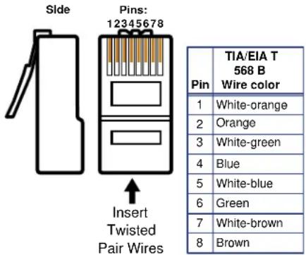
Figure 5. TP Cable Termination
NOTE: Do not use Extron UTP23SF-4 Enhanced Skew-Free AV UTP cable or STP201 cable to link the transmitter and receiver. The DTP DVI 330 Tx/Rx does not work properly with these cables.
Supported cables —
The DTP DVI 330 is compatible with CAT 5e, 6, 6a, and 7 shielded twisted pair (F/UTP, SF/UTP, and S/FTP) and unshielded twisted pair (U/UTP) cable.
Cable recommendations —
Extron recommends using the following practices to achieve full transmission distances up to 330 feet (100 m) and reduce transmission errors.
- Use the following Extron XTP DTP 24 SF/UTP cables and DTP 24 connectors for the best performance:
• XTP DTP 24/1000 Non-Plenum 1000' (305 m) spool 22-236-03
• XTP DTP 24P/1000 Plenum 1000' (305 m) spool 22-235-03
• XTP DTP 24 Plug Package of 10 101-005-02
- If not using XTP DTP 24 cable, at a minimum, Extron recommends 24 AWG, solid conductor, STP cable with a minimum bandwidth of 400 MHz.
• Terminate cables with shielded connectors to the TIA/EIA T 568 B standard. - Use no more than two pass-through points, which may include patch points, punch down connectors, couplers, and power injectors. If these pass-through points are required, use CAT 6 or 6a shielded couplers and punch down connectors.
NOTE: When using CAT5e and CAT6 cable in bundles or conduits, consider the following:
- Do not exceed 40% fill capacity in conduits.
- Do not comb the cable for the first 20 meters, where cables are straightened, aligned, and secured in tight bundles.
- Loosely place cables and limit the use of tie wraps or Velcro®.
- Separate twisted pair cables from AC power cables.
Power supply wiring
NOTES:
- One power supply is included with the transmitter and normally can power both units.
- If you have removed the ground jumpers (see Disconnecting the Ground on page 11) because of ground potential differences, one DTP DVI 330 unit cannot remotely power the other unit. Each unit requires a local power supply.
Figure 6 shows how to wire the connector. Use the supplied tie-wrap to strap the power cord to the extended tail of the connector.
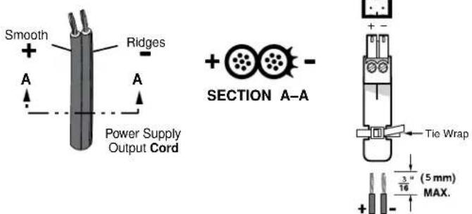
Figure 6. Power Connector Wiring
CAUTION: Electric shock hazard —
- The two power cord wires must be kept separate while the power supply is plugged in. Remove power before wiring.
- The length and preparation of exposed wires is important (see the second and third audio connector NOTES on page 5 for details).
ATTENTION:
- This product is intended to be supplied by a Listed Power Unit marked "Class 2" or "LPS," rated 12 VDC, 1.0 A minimum. Always use a power supply supplied by or specified by Extron. Use of an unauthorized power supply voids all regulatory compliance certification and may cause damage to the supply and the end product.
- Unless otherwise stated, the AC/DC adapters are not suitable for use in air handling spaces or in wall cavities.
- The installation must always be in accordance with the applicable provisions of National Electrical Code ANSI/NFPA 70, article 75 and the Canadian Electrical Code part 1, section 16. The power supply shall not be permanently fixed to a building structure or similar structure.
- Power supply voltage polarity is critical. Incorrect voltage polarity can damage the power supply and the unit. The ridges on the side of the cord (see figure 6) identify the power cord negative lead.
To verify the polarity before connection, plug in the power supply with no load and check the output with a voltmeter.
RS-232 and IR connector wiring
Figure 7 shows how to wire the RS-232 connector.
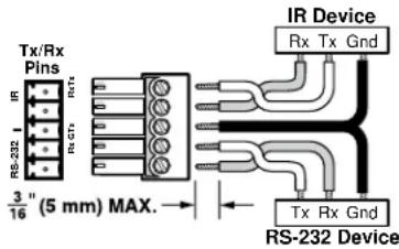
Figure 7. RS-232 Connector Wiring
NOTES:
- The IR Tx and Rx line pair and the RS-232 Tx and Rx line pair must each cross once between this connector and the source or destination.
- The length and preparation of exposed wires is important (see the second and third audio connector NOTES on page 5 for details).
Operation
Figure 8 shows the location of the power indicators on the front and rear panels of the transmitter and receiver.
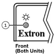
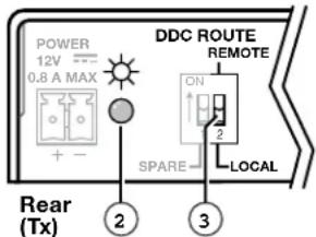
Figure 8. Power Indicators
① Power (and signal) LED (front panel) —
Amber — The unit is receiving power, either locally or remotely (on the DTP cable).
Green — The unit is receiving an active DVI input, either on the DVI input if a transmitter, or transmitted on the DTP cable if a receiver.
② Power LED (rear panel) —
Amber — The unit is receiving power remotely (on the DTP cable).
Green — The unit is receiving power locally.
③ DDC Route switch — This rear panel switch selects either the remote or local DVI display as the DDC reference (for EDID communications).
After the transmitter, the receiver, and their connected devices are powered up, the system is fully operational. If any problems are encountered, ensure all cables are routed and connected properly.
NOTE: Ensure that the video source and display selected for the DDC are properly connected to the transmitter and receiver pair, and that the transmitter, the receiver, and the display have power applied before power is applied to the video source. If the other devices are not turned on before the video source, the image may not appear.
Reference Information
This section provides procedures for mounting the DTP DVI 330 Tx/Rx transmitter and receiver and disconnecting the ground between them.
• Mounting the Transmitter or Receiver
• Disconnecting the Ground
Mounting the Transmitter or Receiver
ATTENTION:
• Installation and service must be performed by authorized personnel only.
- Avoid ground potential differences between the transmitter and receiver installation sites, which can lead to equipment damage or a missing or unstable picture. If a potential difference cannot be avoided, remove the ground connection between the units and locally power both units (see Disconnecting the Ground on the next page).
The 1-inch high, quarter rack width DTP DVI 330 transmitter or receiver can be placed on a table, mounted in a rack, or mounted under a desk or table. The receiver can also be mounted on a projector bracket.
Tabletop Use
Affix the included rubber feet to the bottom of the unit and place it in any convenient location.
Mounting kits
Mount the unit using any optional compatible mounting kit listed on the Extron website (www.extron.com), in accordance with the directions included with the kit. For rack mounting, see UL Rack-Mounting Guidelines on the next page.
UL Rack-Mounting Guidelines
The following Underwriters Laboratories (UL) requirements pertain to the installation of the unit into a rack.
- Elevated operating ambient temperature — If installed in a closed or multi-unit rack assembly, the operating ambient temperature of the rack environment may be greater than room ambient. Therefore, consider installing the equipment in an environment compatible with the maximum ambient temperature (TMA = +122 °F, +50 °C) specified by Extron.
- Reduced air flow — Installation of the equipment in a rack should be such that the amount of air flow required for safe operation of the equipment is not compromised.
- Mechanical loading — Mounting of the equipment in the rack should be such that a hazardous condition is not achieved due to uneven mechanical loading.
- Circuit overloading — Consideration should be given to the connection of the equipment to the supply circuit and the effect that overloading of the circuits might have on overcurrent protection and supply wiring. Appropriate consideration of equipment nameplate ratings should be used when addressing this concern.
- Reliable earthing (grounding) — Reliable earthing of rack-mounted equipment should be maintained. Particular attention should be given to supply connections other than direct connections to the branch circuit (such as use of power strips).
Disconnecting the Ground
If you cannot resolve a ground potential difference between the transmitter and receiver installation sites (as suggested by a missing or unstable picture), remove the ground connection between the units as follows:
NOTE: Once you have removed the ground jumpers, the DTP DVI 330 cannot extend analog audio and one unit cannot remotely power the other. No analog audio is output and each unit requires a local power supply.
- Disconnect any cables and remove the transmitter and receiver from any rack or other installation option.
- Remove and retain the screws securing the covers to the transmitter and receiver. Slide the covers forward slightly and lift them off both units (see figure 9).
• Transmitter — Six screws, two on each side and two on top - Receiver — Eight screws, three on each side and two on top
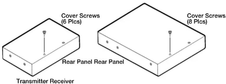
Figure 9. Opening the Transmitter and Receiver
- Locate, lift off, and discard jumpers JMP2 and JMP3 from both units (see figure 10).
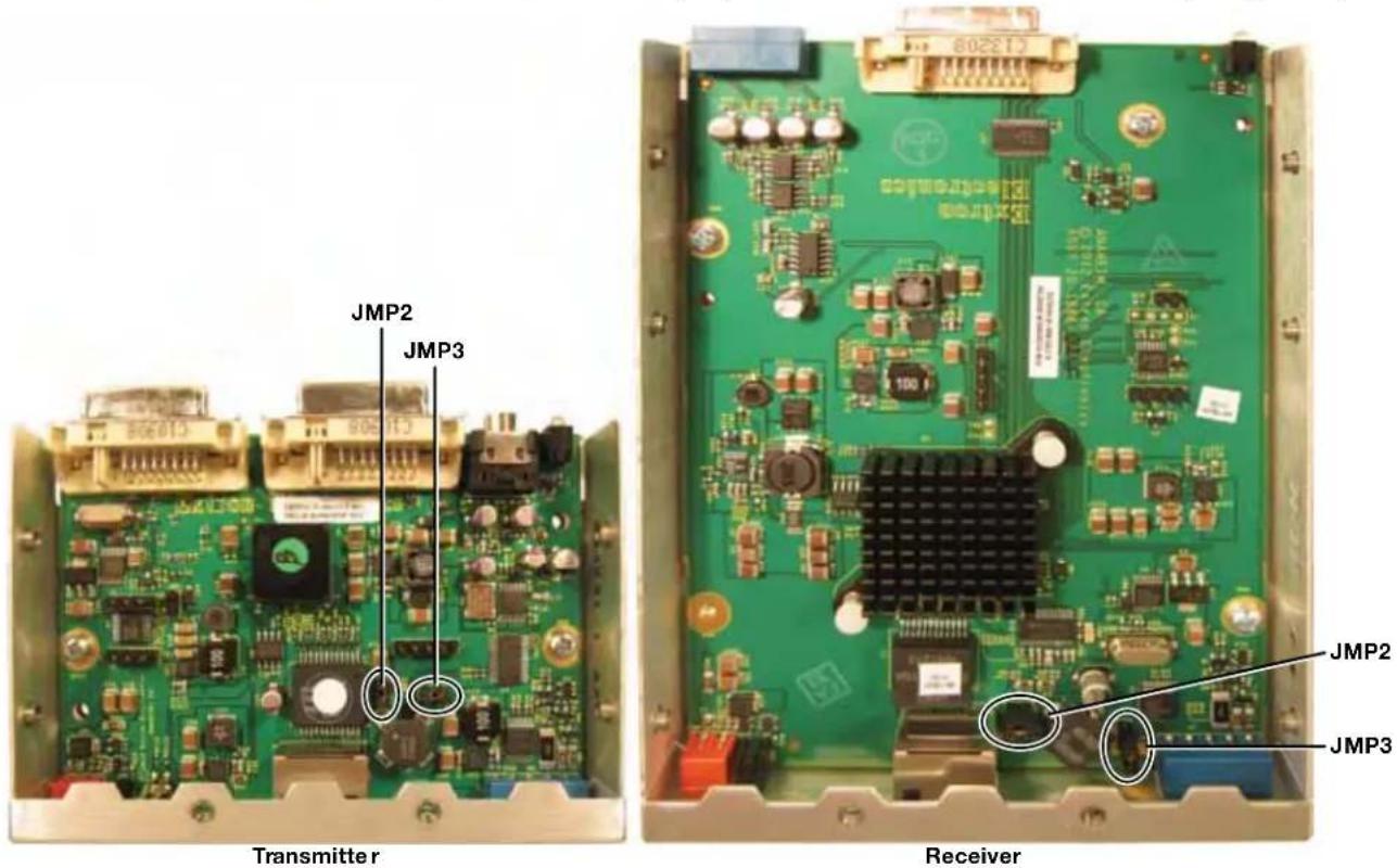
Figure 10. Jumper Locations
- Reinstall the covers on both units, securing them in place with the screws removed in step 2.
- Reinstall both units in their racks or other installation option (see Mounting the Transmitter and Receiver on page 10).
- If you are using shielded cable, disconnect the cable shield from the connector at either end of the cable.
- Obtain a second 12 V power supply (one supply is provided with the transmitter and normally powers both units), and locally power both units (see Power supply wiring on page 8).
Extron Warranty
Extron Electronics warrants this product against defects in materials and workmanship for a period of three years from the date of purchase. In the event of malfunction during the warranty period attributable directly to faulty workmanship and/or materials, Extron Electronics will, at its option, repair or replace said products or components, to whatever extent it shall deem necessary to restore said product to proper operating condition, provided that it is returned within the warranty period, with proof of purchase and description of malfunction to:
USA, Canada, South America, and Central America:
Extron Electronics
1330 South Lewis Street
Anaheim, CA 92805
U.S.A.
Japan:
Extron Electronics, Japan
Kyodo Building, 16 Ichibancho
Chiyoda-ku, Tokyo 102-0082
Japan
Europe and Africa:
Extron Europe
Hanzeboulevard 10
3825 PH Amersfoort
The Netherlands
China:
Extron China
686 Ronghua Road
Songjiang District
Shanghai 201611
China
Asia:
Extron Asia Pte Ltd
135 Joo Seng Road, #04-01
PM Industrial Bldg.
Singapore 368363
Singapore
Middle East:
Extron Middle East
Dubai Airport Free Zone
F12, PO Box 293666
United Arab Emirates, Dubai
This Limited Warranty does not apply if the fault has been caused by misuse, improper handling care, electrical or mechanical abuse, abnormal operating conditions, or if modifications were made to the product that were not authorized by Extron.
NOTE: If a product is defective, please call Extron and ask for an Application Engineer to receive an RA (Return Authorization) number. This will begin the repair process.
USA: 714.491.1500 or 800.633.9876
Europe: 31.33.453.4040
Asia: 65.6383.4400
Japan: 81.3.3511.7655
Units must be returned insured, with shipping charges prepaid. If not insured, you assume the risk of loss or damage during shipment. Returned units must include the serial number and a description of the problem, as well as the name of the person to contact in case there are any questions.
Extron Electronics makes no further warranties either expressed or implied with respect to the product and its quality, performance, merchantability, or fitness for any particular use. In no event will Extron Electronics be liable for direct, indirect, or consequential damages resulting from any defect in this product even if Extron Electronics has been advised of such damage.
Please note that laws vary from state to state and country to country, and that some provisions of this warranty may not apply to you.
| Extron Headquarters+1.800.633.9876 (Inside USA/Canada Only)Extron USA - West Extron USA - East+1.714.491.1500 +1.919.850.1000+1.714.491.1517 FAX +1.919.850.1001 FAX | Extron Europe+800.3987.6673(Inside Europe Only)+31.33.453.4040+31.33.453.4050 FAX | Extron Asia+65.6383.4400+65.6383.4664 FAX | Extron Japan+81.3.3511.7655+81.3.3511.7656 FAX | Extron China+86.21.3760.1568+86.21.3760.1568 FAX | Extron Middle East+971.4.299.1800+971.4.299.1880 FAX | Extron Korea+82.2.3444.1571+82.2.3444.1575 FAX | Extron India1800.3070.3777(Inside India Only)+91.80.3055.3777+91.80.3055.3737 FAX |
- Safety Instructions • English
- Chinese Traditional (繁體中文)
- Specifications Availability
- Conventions Used in this Guide
- Notifications
- Copyright
- Trademarks
- Contents
- Introduction.... 1
- Installation and Operation....3
- Reference Information 10
- Introduction
- About this Guide
- About the DTP DVI 330 Tx/Rx Transmitter and Receiver
- TP Cable Advantages
- Control Communications
- Features
- Installation and Operation
- Mounting the Units
- ATTENTION:
- Connections
- NOTES:
- Connector and Cable Details
- TP cable termination and recommendations
- Supported cables —
- Cable recommendations —
- Power supply wiring
- CAUTION: Electric shock hazard —
- RS-232 and IR connector wiring
- Operation
- Reference Information
- Mounting the Transmitter or Receiver
- Tabletop Use
- Mounting kits
- UL Rack-Mounting Guidelines
- Disconnecting the Ground
- Extron Warranty
- USA, Canada, South America, and Central America:
- Japan:
- Europe and Africa:
- China:
- Asia:
- Middle East:
Brand : Extron
Model : DTP DVI 330 Rx
Category : Audiovisual Equipment