
DVI 101 - Audiovisual Equipment Extron - Free user manual and instructions
Find the device manual for free DVI 101 Extron in PDF.


| Product Type | DVI Cable Equalizer |
| Model | DVI 101 by Extron |
| Dimensions (H x W x D) | 1.0" x 2.2" x 3.0" (2.5 cm x 5.6 cm x 7.6 cm) |
| Weight | 0.4 lbs (0.2 kg) |
| Enclosure | Metal, 1/8 rack wide |
| Power Supply | External 12VDC, 1A regulated (100-240VAC input) or source-powered via DVI pin 14 (5VDC, 0.05A) |
| Maximum Data Rate | 4.95 Gbps (1.65 Gbps per color) |
| Resolution Support | Up to 1920x1200 or 1080p @ 60Hz |
| Input Cable Length | Up to 200' (61 m) at highest resolution; up to 250' (76 m) at lower resolutions |
| Output Cable Length | Up to 15' (5 m) |
| Equalization | Automatic for up to -40 dB cable loss |
| Connectors | 1 female DVI-I input, 1 female DVI-I output (digital only) |
| Standards | DVI 1.0, HDMI 1.2 (with adapter) |
| HDCP Support | Yes, pass-through of HDCP and EDID |
| Front Panel LED | Green = signal present, Yellow = power on |
| Mounting Options | Tabletop (rubber feet), rack shelf (optional), under-desk (optional kit) |
| Cooling | Convection, no vents |
| Operating Temperature | +32 to +122°F (0 to +50°C) |
| Safety Compliance | CE, CUL, UL |
| EMI Compliance | CE, C-tick, FCC Class A, ICES, VCCI |
| Warranty | 3 years parts and labor |
| Included Accessories | 12VDC power supply kit, captive screw connector, IEC power cord, rubber feet, tweeker screwdriver, manual |
| Repair Policy | No user-serviceable parts; refer servicing to qualified personnel |
Frequently Asked Questions - DVI 101 Extron
User questions about DVI 101 Extron
0 question about this device. Answer the ones you know or ask your own.
Ask a new question about this device
Download the instructions for your Audiovisual Equipment in PDF format for free! Find your manual DVI 101 - Extron and take your electronic device back in hand. On this page are published all the documents necessary for the use of your device. DVI 101 by Extron.
USER MANUAL DVI 101 Extron
Safety Instructions • English

This symbol is intended to alert the user of important operating and maintenance (servicing) instructions in the literature provided with the equipment.

This symbol is intended to alert the user of the presence of uninsulated dangerous voltage within the product's enclosure that may present a risk of electric shock.
Caution
Read Instructions • Read and understand all safety and operating instructions before using the equipment.
Retain Instructions • The safety instructions should be kept for future reference.
Follow Warnings • Follow all warnings and instructions marked on the equipment or in the user information.
Avoid Attachments • Do not use tools or attachments that are not recommended by the equipment manufacturer because they may be hazardous.
Power sources • This equipment should be operated only from the power source indicated on the product. This equipment is intended to be used with a main power system with a grounded (neutral) conductor. The third (grounding) pin is a safety feature, do not attempt to bypass or disable it.
Power disconnection • To remove power from the equipment safely, remove all power cords from the rear of the equipment, or the desktop power module (if detachable), or from the power source receptacle (wall plug).
Power cord protection • Power cords should be routed so that they are not likely to be stepped on or pinched by items placed upon or against them.
Servicing • Refer all servicing to qualified service personnel. There are no user-serviceable parts inside. To prevent the risk of shock, do not attempt to service this equipment yourself because opening or removing covers may expose you to dangerous voltage or other hazards.
Slots and openings • If the equipment has slots or holes in the enclosure, these are provided to prevent overheating of sensitive components inside. These openings must never be blocked by other objects.
Lithium battery • There is a danger of explosion if battery is incorrectly replaced. Replace it only with the same or equivalent type recommended by the manufacturer. Dispose of used batteries according to the manufacturer's instructions.
Avertissement
This equipment has been tested and found to comply with the limits for a Class A digital device, pursuant to part 15 of the FCC Rules. Operation is subject to the following two conditions: (1) this device may not cause harmful interference, and (2) this device must accept any interference received, including interference that may cause undesired operation. The Class Alimits are designed to provide reasonable protection against harmful interference when the equipment is operated in a commercial environment. This equipment generates, uses, and can radiate radio frequency energy and, if not installed and used in accordance with the instruction manual, may cause harmful interference to radio communications. Operation of this equipment in a residential area is likely to cause harmful interference, in which case the user will be acquired to correct the interference at his own expense.

natural_image
Pure horizontal black line on white background (no text or symbols)Chapter One • Introduction....1-1
About this Manual 1-2
About the DVI 101 and HDMI 101 Cable Equalizers ..... 1-2
Features 1-3
Application Diagrams 1-3
Chapter Two • Installation and Operation ..... 2-1
Mounting the DVI 101 and HDMI 101 2-2
Tabletop use 2-2
Rack mounting 2-2
UL rack mounting guidelines 2-2
Rack mounting procedure 2-3
Furniture mounting 2-4
Front and Back Panel Features and Connections ...... 2-5
Input cable lengths 2-7
Powering Via the Input Source 2-9
Connecting for Long Cable Runs 2-9
Appendix A• Specifications, Parts, and Accessories ......A-1
Specifications – DVI 101....A-2
Specifications – HDMI 101 ......A-4
Included Parts ......A-6
DVI 101....A-6
HDMI 101 ......A-6
Optional Accessories ......A-7
Cables and Adapters ......A-7
All trademarks mentioned in this manual are the properties of their respective owners.
68-1447-01 Rev. B
01 09
Chapter One
Introduction
About this Manual
About the DVI 101 and HDMI 101 Cable Equalizers
Features
Application Diagrams
About this Manual
This manual contains information about the Extron DVI 101 and HDMI 101 Cable Equalizers and describes procedures for connecting and operating them.
In this manual, the term “equalizer” is used to refer to either the DVI 101 or the HDMI 101 Cable Equalizer. "DVI/HDMI" refers to either product or to both products.
About the DVI 101 and HDMI 101 Cable Equalizers
The Extron DVI 101 and HDMI 101 are compact, economical cable equalizers that extend Digital Visual Interface (DVI) and High Definition Multimedia Interface (HDMI) signals beyond the specified cable limits of 15' (5 m) for DVI and 45' (14 m) for HDMI.
The DVI 101 and HDMI 101 attach to the end of a long cable run of up to 200' (61 m). They automatically provide the necessary active equalization to ensure optimal image quality with HDTV 1080p and high resolution computer video signals up to 1920x1200. They are ideal for both temporary applications and permanent installations with long DVI or HDMI cable runs.
- The DVI 101 passes Extended Display Identification Data (EDID) information and supports the long distance transmission of HDTV signals with High-bandwidth Digital Content Protection (HDCP) for copy protection of digital television broadcasts and high resolution digital video output from DVD, HD DVD, and Blu-rayDisc™ players.
With the appropriate adapters from Extron, the DVI 101 is fully compatible with the HDMI digital video, audio, and control standard for audio/video products.
- The HDMI 101 is fully HDMI-compliant for extending digital video, multi-channel audio, and control signals from HDMI-equipped devices. It is also HDCP compliant, enabling long distance transmission of HDTV signals with HDCP.
With the appropriate adapters from Extron, the HDMI 101 is fully compatible with the DVI digital video, audio, and control standard for audio/video products.
At shorter distances, the DVI 101 and HDMI 101 can be powered by the source device via the DVI or HDMI cable, eliminating the external power supply. See the "Recommended maximum cable lengths" table on page 2-8 for these distances.
Features
- Power/Signal indicator — The LED on the front panel lights green to indicate source signal presence and yellow to indicate power on.
- Source-powering at short distances — The DVI/HDMI can receive power from an attached input source device, eliminating the need for power supply installation (see the table on page 2-8).
- DDC and HDCP copy protection transmission support — DDC channels are actively buffered, allowing pass-through of EDID and HDCP information between source and display.
- Enclosure — Compact 1" (2.5 cm) high, 1/8 rack wide metal enclosure
- Rack and furniture mounting — The equalizers can be mounted on a rack shelf or under a desk or podium.
- Power supply — An external international power supply with a two-pin captive screw connector accepts 100 to 240 VAC.
Application Diagrams
The following diagrams show examples of how the DVI 101 and HDMI 101 can be connected.
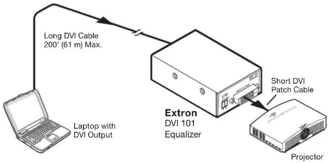
flowchart
graph TD
    A["Laptop with DVI Output"] --> B["Long DVI Cable 200' (61 m) Max."]
    B --> C["Extron DVI 101 Equalizer"]
    C --> D["Short DVI Patch Cable"]
    C --> E["Projector"]
DVI 101 application diagram
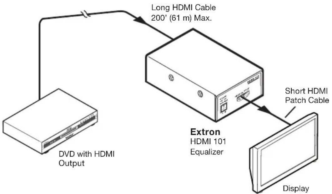
flowchart
graph TD
    A["Extron HDMI 101 Equalizer"] -->|Long HDMI Cable 200' (61 m) Max.| B["DVD with HDMI Output"]
    A -->|Short HDMI Patch Cable| C["Display"]
HDMI 101 application diagram
Chapter Two
Installation and Operation
Mounting the DVI 101 and HDMI 101
Front and Back Panel Features and Connections
Powering Via the Input Source
Connecting for Long Cable Runs
Mounting the DVI 101 and HDMI 101
The DVI 101 and HDMI 101 can be mounted on a rack shelf, under furniture, or placed on a table top. See "Optional Accessories", in appendix A, "Specifications, Parts, and Accessories", for information on the mounting products available for the DVI/HDMI 101.
Tabletop use
Four self-adhesive rubber feet are included with the DVI/HDMI. For tabletop use, attach one foot at each corner on the bottom surface of the unit.
Rack mounting
Extron has a variety of optional rack shelf and furniture mounting kits that can be used with the DVI/HDMI 101. See "Optional Accessories", in appendix A, "Specifications, Parts, and Accessories", for a list of these mounting options.
UL rack mounting guidelines
The following Underwriters Laboratories (UL) guidelines apply to the safe installation of the equipment in a rack.
- Elevated operating ambient temperature — If the equipment is installed in a closed or multi-unit rack assembly, the operating ambient temperature of the rack environment may be greater than room ambient temperature. Therefore, install the equipment in an environment compatible with the maximum ambient temperature specified by Extron (Tma = +122 °F, +50 °C).
- Reduced air flow — Install the equipment in a rack so that the amount of air flow required for safe operation of the equipment is not compromised.
- Mechanical loading — When mounting the equipment in the rack, ensure that uneven mechanical loading does not cause a hazardous condition.
- Circuit overloading — When connecting the equipment to the supply circuit, consider the effect that circuit overloading might have on overcurrent protection and supply wiring. Consider the equipment nameplate ratings when addressing this concern.
- Reliable earthing (grounding) — Maintain reliable grounding of rack-mounted equipment. Pay particular attention to supply connections other than direct connections to the branch circuit (e.g., use of power strips).
Rack mounting procedure
For optional rack mounting, mount the DVI/HDMI on one of the rack shelves listed above. On the standard 9.5" or 6" deep rack shelf, the equalizer mounts in one of eight possible locations to the rear of the rack.
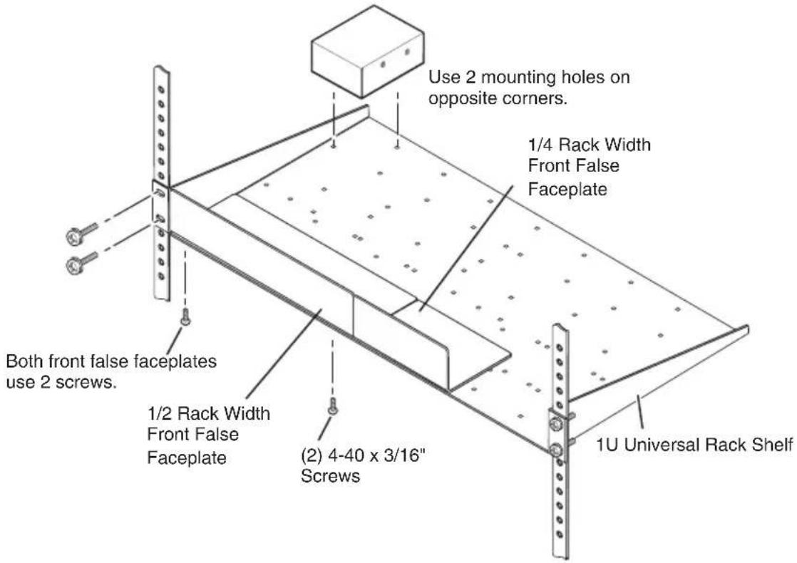
Mounting the DVI 101 or HDMI 101 on a standard 9.5" deep rack shelf
-
If rubber feet were previously installed on the bottom of the unit, remove them.
-
Secure the DVI/HDMI onto the rack shelf, using two 4-40 x 3/16" screws in opposite (diagonal) corners.
-
Install blank panel(s) or other unit(s) on the rack shelf as desired.
-
Insert the shelf into the rack, aligning the holes in the shelf with those of the rack.
-
Secure the shelf to the rack using the supplied machine screws. This shelf can be mounted in the front or in the rear of the rack.
Furniture mounting
To mount the DVI 101 or the HDMI 101 under a desk top, podium, or other furniture, use the optional MBU 125 Underdesk Mounting Kit (part #70-077-01), as follows:
- If rubber feet were previously attached to the bottom of the unit, remove them.
- Remove the screws from one side of the DVI/HDMI. Retain the screws for possible later reassembly.
- Attach one bracket to the side of the unit, using the provided machine screws (see the illustration below).
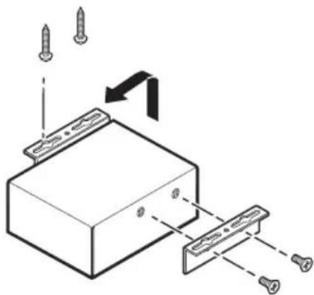
natural_image
Technical diagram of a mechanical assembly with screws and a block, showing alignment and mounting features (no text or symbols)Under-desk mounting the DVI/HDMI
- Repeat steps 2 and 3 on the other side of the DVI/HDMI.
- Hold the unit with the attached brackets against the underside of the table or other furniture. On the mounting surface, mark the location of the bracket's screw holes.
- Drill 3/32" (2 mm) diameter pilot holes, 1/4" (6.3 mm) deep in the mounting surface at the marked screw locations.
- Insert #8 wood screws into the four pilot holes. Tighten each screw into the mounting surface until slightly less than 1/4" of the screw head protrudes.
- Align the mounting screws with the slots in the brackets and place the unit against the surface, with the screws through the bracket slots.
- Slide the unit slightly forward or back, then tighten all four screws to secure it in place.
Front and Back Panel Features and Connections
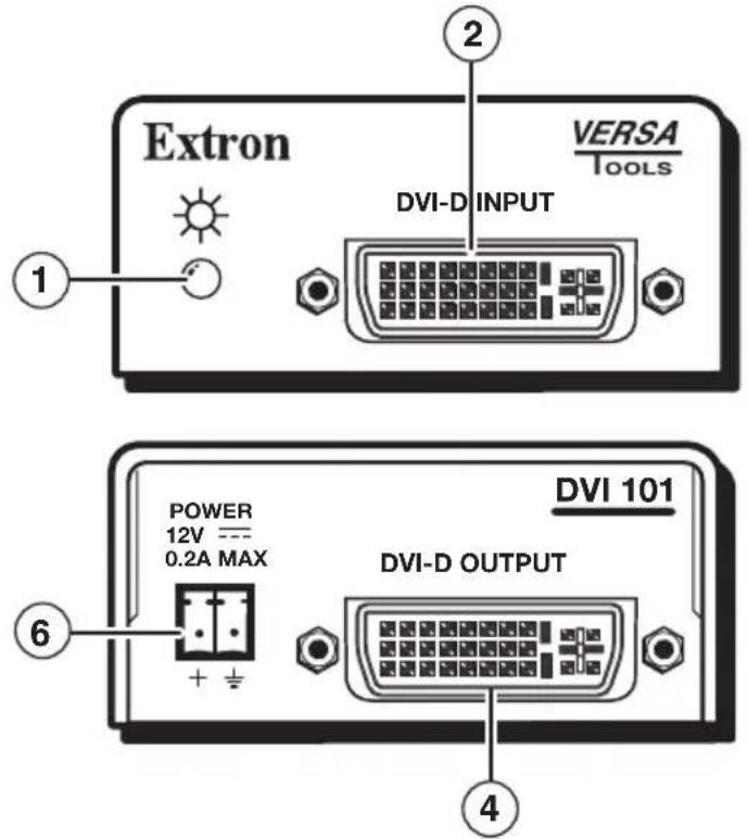
DVI 101 front and rear panels
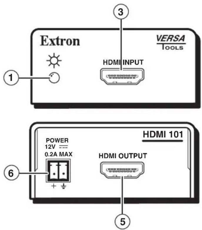
HDMI 101 front and rear panels
① Power/signal status LED — This dual-color LED lights yellow when the DVI/HDMI is receiving power. When a DVI or HDMI input signal is present, this LED lights green.
NOTE If the LED does not light when you are attempting to power the unit from the source device, use an external power supply instead.
② DVI input connector (DVI 101 only) — Plug the cable from the input source device into this single link format female DVI-I connector. The table and diagrams below show the DVI pin configuration.
NOTE The analog pins are not implemented.
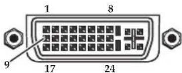
Female Connector
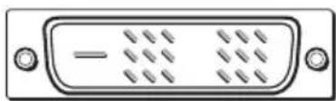
natural_image
Front view of a D-sub connector with no visible text or symbolsMale Connector
| Pin | Signal | Pin | Signal | Pin | Signal |
| 1 | TMDS data 2– 9 | TMDS data 1– 17 | TMDS data 0– | ||
| 2 | TMDS data 2+ 10 | TMDS data 1+ 18 | TMDS data 0+ | ||
| 3 | TMDS data 2 11shield shield | TMDS data 1 19 shield | TMDS data 0 | ||
| 4 | Spare 12 | Spare 20 | Spare | ||
| 5 | Spare 13 | Spare 21 | Spare | ||
| 6 | DDC clock 14 | +5 V power 22 | TMDS clock shield | ||
| 7 | DDC data 15 | Ground (+5 V) 23 | TMDS clock+ | ||
| 8 | CEC control 16 | Hot plug detect 24 | TMDS clock– | ||
DVI connector pin assignments
③ HDMI input connector (HDMI 101 only) — Plug the cable from the input source device into this female HDMI type A connector. The table and diagrams below show the HDMI pin configuration.
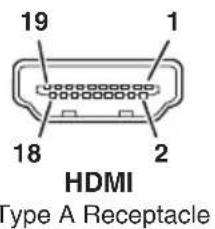
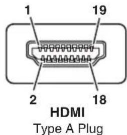
| Pin | Signal | Pin | Signal | Pin | Signal |
| 1 | TMDS data 2+ 7 | TMDS data 0– 13 | CE control | ||
| 2 | TMDS data 2 8shield shield | TMDS data 0 14 Reserved (NC) | |||
| 3 | TMDS data 2– 9 | TMDS data 0– 15 SCL | |||
| 4 | TMDS data 1+ 10 | TMDS clock+ 16 SDA | |||
| 5 | TMDS data 1shield | 11 TMSD clockshield ground | 17 | DDC/CEC | |
| 6 | TMDS data –1 | 12 TMDS clock– 18 +5 V power | |||
| 19 | Hot plugdetect | ||||
HDMI connector pin assignments
Input cable lengths
The maximum input cable length for the two equalizers is 200' (61 m), for the highest transmission rate of 165 MHz. Longer cables may be used at a lower rate. High quality cable can increase the distance and rate of transmission. However, the achievable distance and speed are also contingent on the sensitivity of the input source and the display device and on the source of power to the equalizer (external or input source).
The table on the next page shows the maximum cable lengths recommended for each resolution, depending on whether the equalizer is powered from the input source or an external power supply.
NOTE
Avoid using couplers and adapters between cables, as this can result in signal degradation.
Recommended maximum cable lengths
| Video resolution | Powered from source | Powered from external supply |
| 640x480480p | 150' (46 m) 275' (84 m) | |
| 1024x7681280x1024720p1080i | 150' (46 m) 250' (76 m) | |
| 1600x12001920x12001080p | 125' (38 m) 200' (61 m) |
④ DVI output connector (DVI 101 only) — Plug the cable from a DVI output device into this single link format DVI-I connector, following the pin configuration shown in the table on page 2-6. Output signals are digital only.
NOTE For the output, use cables that are 15' (5 m) or less.
⑤ HDMI output connector (HDMI 101 only) — Plug the cable from an output device into this female HDMI Type A connector, following the pin configuration shown in the table on page 2-7.
NOTE For the output, use cables that are 15' (5 m) or less.
⑥ Power connector — Plug the external 12 V power supply (provided with the unit) into this 2-pole captive screw connector. The figure below shows how to wire the connector.
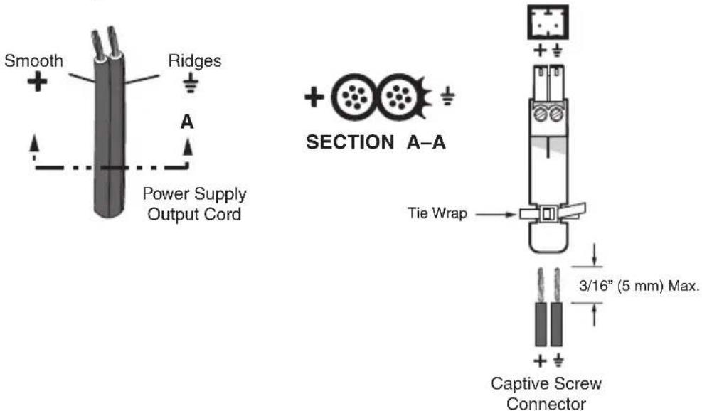
Wiring the power connector
CAUTION
When you are connecting the power supply, voltage polarity is extremely important. Applying power with incorrect voltage polarity could damage the power supply and the equalizer. Identify the negative lead by the ridges on the side of the cord (see the illustration on page 2-8).
CAUTION
Do not tin the stripped power supply leads before installing the captive screw connector. Tinned wires are not as secure in the captive screw connectors and could be pulled out.
WARNING
The two power cord wires must be kept separate while the power supply is plugged in. Remove power before continuing.
To verify the polarity before connection, plug in the power supply with no load and check the output with a voltmeter.
Powering Via the Input Source
For shorter distances, the DVI 101 and the HDMI 101 can receive power from the input device via the 5 VDC signal on pin 14 of the DVD 101 or pin 18 of the HDMI 101 (see the table on page 2-8). This eliminates the external power supply. However, for best unit performance, the external supply is recommended.
NOTE
If the source does not adequately supply the +5 V power, an external power supply must be used.
To verify if the source is providing power, connect a short DVI/HDMI cable from the input device to the input of the DVI/HDMI. If the DVI 101 front panel LED lights yellow, the source is supplying power.
Connecting for Long Cable Runs
To use the DVI 101 or HDMI 101 effectively in a long cable run between the source and the display, position the DVI/HDMI at the end of the cable closest to the display. See the diagram below for an example.

flowchart
graph LR
    A["DVI Source"] -->|Long Input Cable (3' - 200')| B["DVI/HDMI 101"]
    B -->|Short Input Cable (< 15')| C["Display"]
Connecting the DVI/HDMI for a long cable run between the source and the display
Appendix A
Specifications, Parts, and Accessories
Specifications – DVI 101
Specifications – HDMI 101
Included Parts
Optional Accessories
Cables and Adapters
Specifications - DVI 101
NOTE Appropriate HDMI-to-DVI cables or adapters are required for HDMI signal input/output.
Video
Maximum data rate.... 4.95 Gbps (1.65 Gbps per color)
Pixel clock frequency 165 MHz (maximum)
Resolution range ...... Up to 1920x1200 or 1080p @ 60 Hz
Formats ...... RGB and YCbCr digital video
Standards ...... DVI 1.0, HDMI 1.2
Video input
Number/signal type ...... 1 single link DVI-D (HDMI if using an adapter)
Connectors 1 female DVI-I
Input cable length .... Up to 200' (61 m) at 1920x1200 or 1080p @ 60 Hz
Up to 250' (76 m) at 1024x768, 720p, or 1080i @ 60 Hz
Longer distances are possible with lower rates and/or high quality cable.
NOTE The transmission distance varies greatly depending on the signal resolution and on the type of cable, graphic card, and display used in the system.
Equalization ...... Automatic for up to -40 dB of cable loss
Video output
Number/signal type ...... 1 single link DVI-D (HDMI if using an adapter)
Connectors 1 female DVI-I
Output cable length .... Up to 15' (5 m)
General
Power ...... Supplied by an external power supply or by the 5 V signal from a DVI source (pin 14), or an HDMI source (pin 18)
External power supply .... 100 VAC to 240 VAC, 50/60 Hz, external; to 12 VDC, 1 A, regulated
| Power input requirements ...... | 12 VDC, 0.2 A from an external power supply or5 VDC, 0.05 A from a DVI source or an HDMI source |
| Temperature/humidity ...... | Storage: -40 to +158 °F (-40 to +70 °C) /10% to 90%, noncondensingOperating: +32 to +122 °F (0 to +50 °C) /10% to 90%, noncondensing |
| Cooling ...... | Convection, no vents |
| Mounting | |
| Rack mount ...... | Yes, with optional 1U, 9.5" deep rack shelf, part #60-190-01 (RSU 129) or #60-604-01 (RSB 129); 1U, 6" deep rack shelf,part #60-190-10 (RSU 126) or #60-604-10 (RSB 126); or 3.5" deep VersaTools®rack shelf, part #60-190-20 (RSF 123) or#60-604-20 (RSB 123) |
| Furniture mount ...... | Yes, with optional under-desk mounting kit, part #70-077-01 (MBU 125) |
| Enclosure type ...... | Metal |
| Enclosure dimensions...... | 1.0" H x 2.2" W x 3.0" D (one-eighth rack wide)(2.5 cm H x 5.6 cm W x 7.6 cm D) |
| Product weight ...... | 0.4 lbs (0.2 kg) |
| Shipping weight ...... | 2 lbs (1 kg) |
| Vibration ...... | ISTA 1A in carton(International Safe Transit Association) |
| Regulatory compliance | |
| Safety ...... | CE, CUL, UL |
| EMI/EMC ...... | CE, C-tick, FCC Class A, ICES, VCCI |
| MTBF ...... | 30,000 hours |
| Warranty ...... | 3 years parts and labor |
NOTE All nominal levels are at ±10%.
NOTE Specifications are subject to change without notice.
Specifications – HDMI 101
NOTE Appropriate DVI-to-HDMI cables or adapters are required for DVI signal input/output.
Video
Maximum data rate.... 4.95 Gbps (1.65 Gbps per color)
Pixel clock frequency 1.65 MHz (maximum)
Resolution range ...... Up to 1920x1200 or 1080p @ 60 Hz
Formats ...... RGB and YCbCr digital video
Standards ...... DVI 1.0, HDMI 1.2
Video input
Number/signal type ...... 1 single link HDMI (DVI-D if using an adapter)
Connectors 1 female HDMI Type A
Input cable length .... Up to 200' (61 m) at 1920x1200 or 1080p @ 60 Hz
Up to 250' (76 m) at 1024x768, 720p, or 1080i @ 60 Hz
Longer distances are possible with lower rates and/or high quality cable.
NOTE The transmission distance varies greatly depending on the signal resolution and on the type of cable, graphic card, and display used in the system.
Equalization ...... Automatic for up to -40 dB of cable loss
Video output
Number/signal type ...... 1 single link HDMI (DVI-D if using an adapter)
Connectors 1 female HDMI
Output cable length .... Up to 15' (5 m)
General
Power ...... Supplied by an external power supply or by the 5 V signal from an HDMI source (pin 18), or a DVI source (pin 14)
External power supply .... 100 VAC to 240 VAC, 50/60 Hz, external; to 12 VDC, 1 A, regulated
Power input requirements .... 12 VDC, 0.2 A from an external power supply or 5 VDC, 0.05 A from an HDMI or DVI source
Temperature/humidity ...... Storage: -40 to +158 °F (-40 to +70 °C) / 10% to 90%, noncondensing Operating: +32 to +122 °F (0 to +50 °C) / 10% to 90%, noncondensing
Cooling ...... Convection, no vents
Rack mount.... Yes, with optional 1U, 9.5" deep rack shelf, part #60-190-01 (RSU 129) or #60-604-01 (RSB 129); 1U, 6" deep rack shelf, part #60-190-10 (RSU 126) or #60-604-10 (RSB 126); or 3.5" deep VersaTools® rack shelf, part #60-190-20 (RSF 123) or #60-604-20 (RSB 123) Also furniture-mountable with optional under-desk mounting kit, part #70-077-01 (MBU 125)
Enclosure type ...... Metal
Enclosure dimensions.... 1.0" H x 2.2" W x 3.0" D (one-eighth rack wide) (2.5 cm H x 5.6 cm W x 7.6 cm D)
Product weight 0.4 lbs (0.2 kg)
Shipping weight 2 lbs (1 kg)
Vibration ...... ISTA 1A in carton (International Safe Transit Association)
Regulatory compliance
Safety ...... CE, CUL, UL
EMI/EMC ...... CE, C-tick, FCC Class A, ICES, VCCI
MTBF 30,000 hours
Warranty 3 years parts and labor
NOTE All nominal levels are at ±10%.
NOTE Specifications are subject to change without notice.
Included Parts
DVI 101
These items are included in each order for the DVI 101:
| Included parts | Replacement part number |
| DVI 101 Equalizer 60-873-01 | |
| 12 VDC, 1 A external power supply kit 70-055-01 | |
| 3.5 mm, 2-pole captive screw connector with tail | 10-702-10LF |
| IEC power cord | |
| Rubber feet, 4, unattached | |
| Tweeker (small screwdriver) | |
| DVI 101 and HDMI 101 User's Manual | |
HDMI 101
These items are included in each order for the HDMI 101:
| Included parts | Replacement part number |
| HDMI 101 Equalizer 60-872-01 | |
| 12 VDC, 1 A external power supply kit 70-055-01 | |
| 3.5 mm, 5-pole captive screw connector 10-702-10LF | |
| IEC power cord | |
| Rubber feet, 4, unattached | |
| Tweeker (small screwdriver) | |
| DVI 101 and HDMI 101 User's Manual |
Optional Accessories
The following items are optional and can be purchased separately for the DVI 101 and/or the HDMI 101.
| Accessories Part number | |
| MBU 125 Under-desk Mount Kit | 70-077-01 |
| RSU 129 1U, 9.5" deep, universal rack shelf kit | 60-190-01 |
| RSB 129 1U, 9.5" deep, basic rack shelf 60-604-01 | |
| RSU 126 1U, 6" deep, universal rack shelf kit | 60-190-10 |
| RSB 126 1U, 6" deep, basic rack shelf 60-604-10 | |
| RSF 123 1U, 3.5" deep, VersaTools® rack shelf kit | 60-190-20 |
| RSB 123 1U, 3.5" deep, basic VersaTools rack shelf | 60-604-20 |
Cables and Adapters
The following cables and adapters may be purchased for use with the DVI 101 and/or the HDMI 101.
| Cable/Adapter Part number | |
| IN9700 Series DVI (25', 35', 50', and 75' lengths) | 26-584-xx |
| DVID SL Series DVI (3', 6', and 15' lengths) | 26-585-xx |
| HDMI M-DVI-D M Series DVI to HDMI (3', 6', 12', 25', 35', and 50' lengths) | 26-614-xx |
| HDMI M-M Series HDMI (3', 6', 12', 25', 35', and 50' lengths) | 26-613-xx |
| HDMIM-DVIDF HDMI male to DVI-D female adapter | 26-617-01 |
| HDMIM-DVIDM HDMI female to DVI-D male adapter | 26-616-01 |
| HDMIF-DVIDF HDMI female to DVI-D female adapter | 26-618-01 |
This page was intentionally left blank.
Extron's Warranty
Extron Electronics warrants this product against defects in materials and workmanship for a period of three years from the date of purchase. In the event of malfunction during the warranty period attributable directly to faulty workmanship and/or materials, Extron Electronics will, at its option, repair or replace said products or components, to whatever extent it shall deem necessary to restore said product to proper operating condition, provided that it is returned within the warranty period, with proof of purchase and description of malfunction to:
USA, Canada, South America, and Central America:
Extron USA
1001 East Ball Road
Anaheim, CA 92805
U.S.A.
Europe, Africa, and the Middle East:
Extron Europe
Hanzeboulevard 10
3825 PH Amersfoort
The Netherlands
Asia:
Extron Asia
135 Joo Seng Road #04-01
PM Industrial Bldg.
Singapore 368363
Singapore
Japan:
Extron Japan
Kyodo Building, 16 Ichibancho
Chiyoda-ku, Tokyo 102-0082
Japan
China:
Extron China
686 Ronghua Road
Songjiang District
Shanghai 201611
China
Middle East:
Extron Middle East
Dubai Airport Free Zone
F12, PO Box 293666
United Arab Emirates, Dubai
This Limited Warranty does not apply if the fault has been caused by misuse, improper handling care, electrical or mechanical abuse, abnormal operating conditions or non-Extron authorized modification to the product.
If it has been determined that the product is defective, please call Extron and ask for an Applications Engineer at (714) 491-1500 (USA), 31.33.453.4040 (Europe), 65.6383.4400 (Asia), or 81.3.3511.7655 (Japan) to receive an RA# (Return Authorization number). This will begin the repair process as quickly as possible.
Units must be returned insured, with shipping charges prepaid. If not insured, you assume the risk of loss or damage during shipment. Returned units must include the serial number and a description of the problem, as well as the name of the person to contact in case there are any questions.
Extron Electronics makes no further warranties either expressed or implied with respect to the product and its quality, performance, merchantability, or fitness for any particular use. In no event will Extron Electronics be liable for direct, indirect, or consequential damages resulting from any defect in this product even if Extron Electronics has been advised of such damage.
Please note that laws vary from state to state and country to country, and that some provisions of this warranty may not apply to you.
| Extron USA-WestHeadquarters | Extron USA-East | Extron Europe | Extron Asia | Extron Japan | Extron China | Extron Middle East |
| +800.633.9876Inside USA / Canada Only | +800.633.9876Inside USA / Canada Only | +800.3987.6673Inside Europe Only | +800.7339.8766Inside Asia Only | +81.3.3511.7655+81.3.3511.7656 FAX | +400.883.1568Inside China Only | +971.4.2991800+971.4.2991880 FAX |
| +1.919.863.1794+1.919.863.1797 FAX | +31.33.453.4040+31.33.453.4050 FAX | +65.6383.4400+65.6383.4664 FAX | +86.21.3760.1568+86.21.3760.1566 FAX |
- Safety Instructions • English
- Caution
- Avertissement
- Chapter One • Introduction....1-1
- Chapter Two • Installation and Operation ..... 2-1
- Appendix A• Specifications, Parts, and Accessories ......A-1
- Chapter One
- Introduction
- About this Manual
- About the DVI 101 and HDMI 101 Cable Equalizers
- Features
- Application Diagrams
- Chapter Two
- Installation and Operation
- Mounting the DVI 101 and HDMI 101
- Tabletop use
- Rack mounting
- UL rack mounting guidelines
- Rack mounting procedure
- Mounting the DVI 101 or HDMI 101 on a standard 9.5" deep rack shelf
- Furniture mounting
- Under-desk mounting the DVI/HDMI
- Front and Back Panel Features and Connections
- HDMI connector pin assignments
- Input cable lengths
- NOTE
- WARNING
- Powering Via the Input Source
- Connecting for Long Cable Runs
- Appendix A
- Specifications, Parts, and Accessories
- Specifications - DVI 101
- Video
- Video input
- Video output
- General
- Specifications – HDMI 101
- Included Parts
- DVI 101
- HDMI 101
- Optional Accessories
- Cables and Adapters
- Extron's Warranty
- USA, Canada, South America, and Central America:
- Europe, Africa, and the Middle East:
- Asia:
- Japan:
- China:
- Middle East:
Brand : Extron
Model : DVI 101
Category : Audiovisual Equipment