CRK-1VH4U2TP-330 - Unspecified Rose - Free user manual and instructions
Find the device manual for free CRK-1VH4U2TP-330 Rose in PDF.

User questions about CRK-1VH4U2TP-330 Rose
0 question about this device. Answer the ones you know or ask your own.
Ask a new question about this device
Download the instructions for your Unspecified in PDF format for free! Find your manual CRK-1VH4U2TP-330 - Rose and take your electronic device back in hand. On this page are published all the documents necessary for the use of your device. CRK-1VH4U2TP-330 by Rose.
USER MANUAL CRK-1VH4U2TP-330 Rose
Rose Electronics warrants the CrystalView USB2 to be in good working order for one year from the date of purchase from Rose Electronics or an authorized dealer. Should this product fail to be in good working order at any time during this one-year warranty period, Rose Electronics will, at its option, repair or replace the Unit as set forth below. Repair parts and replacement units will be either reconditioned or new. All replaced parts become the property of Rose Electronics. This limited warranty does not include service to repair damage to the Unit resulting from accident, disaster, abuse, or unauthorized modification of the Unit, including static discharge and power surges.
Limited Warranty service may be obtained by delivering this unit during the one-year warranty period to Rose Electronics or an authorized repair center providing a proof of purchase date. If this Unit is delivered by mail, you agree to insure the Unit or assume the risk of loss or damage in transit, to prepay shipping charges to the warranty service location, and to use the original shipping container or its equivalent. You must call for a return authorization number first. Under no circumstances will a unit be accepted without a return authorization number. Contact an authorized repair center or Rose Electronics for further information.
ALL EXPRESS AND IMPLIED WARRANTIES FOR THIS PRODUCT INCLUDING THE WARRANTIES OF MERCHANTABILITY AND FITNESS FOR A PARTICULAR PURPOSE, ARE LIMITED IN DURATION TO A PERIOD OF ONE YEAR FROM THE DATE OF PURCHASE, AND NO WARRANTIES, WHETHER EXPRESS OR IMPLIED, WILL APPLY AFTER THIS PERIOD. SOME STATES DO NOT ALLOW LIMITATIONS ON HOW LONG AN IMPLIED WARRANTY LASTS, SO THE ABOVE LIMITATION MAY NOT APPLY TO YOU.
IF THIS PRODUCT IS NOT IN GOOD WORKING ORDER AS WARRANTED ABOVE, YOUR SOLE REMEDY SHALL BE REPLACEMENT OR REPAIR AS PROVIDED ABOVE. IN NO EVENT WILL ROSE ELECTRONICS BE LIABLE TO YOU FOR ANY DAMAGES INCLUDING ANY LOST PROFITS, LOST SAVINGS OR OTHER INCIDENTAL OR CONSEQUENTIAL DAMAGES ARISING OUT OF THE USE OF OR THE INABILITY TO USE SUCH PRODUCT, EVEN IF ROSE ELECTRONICS OR AN AUTHORIZED DEALER HAS BEEN ADVISED OF THE POSSIBILITY OF SUCH DAMAGES, OR FOR ANY CLAIM BY ANY OTHER PARTY.
SOME STATES DO NOT ALLOW THE EXCLUSION OR LIMITATION OF INCIDENTAL OR CONSEQUENTIAL DAMAGES FOR CONSUMER PRODUCTS, SO THE ABOVE MAY NOT APPLY TO YOU. THIS WARRANTY GIVES YOU SPECIFIC LEGAL RIGHTS AND YOU MAY ALSO HAVE OTHER RIGHTS WHICH MAY VARY FROM STATE TO STATE.
IBM, AT, and PS/2 are trademarks of International Business Machines Corp. Microsoft and Microsoft Windows are registered trademarks of Microsoft Corp. Any other trademarks mentioned in this manual are acknowledged to be the property of the trademark owner.
TABLE of CONTENTS
Contents Page
Disclaimer....1
System introduction....1
Features....2
Cable Requirements 2
Compatibility 2
Package Contents....2
Rose Electronics Web Site 2
CrystalView USB2 Models 3
Connectors.... 3
Installation 4
Transmitter installation....5
Receiver Installation....5
Transmitter to Receiver installation 5
Connecting monitor(s) and USB Devices 5
First time power up sequence....5
Operating procedure 6
Keyboard Commands 6
LED Indicator Descriptions 6
Troubleshooting....7
Maintenance and Repair 8
Technical Support 8
Safety 9
Figures Page
Figure 1 - Typical Configuration .... 4
Tables Page
Table 1 - Keyboard Commands ...... 6
Table 2 - LED Indicators....6
Appendix Page
Appendix A. General Specifications.... 10
INTRODUCTION
Disclaimer
While every precaution has been taken in the preparation of this manual, the manufacturer assumes no responsibility for errors or omissions. Neither does the manufacturer assume any liability for damages resulting from the use of the information contained herein. The manufacturer reserves the right to change the specifications, functions, or circuitry of the product without notice.
The manufacturer cannot accept liability for damages due to misuse of the product or other circumstances outside the manufacturer's control. The manufacturer will not be responsible for any loss, damage, or injury arising directly or indirectly from the use of this product.
System introduction
Thank you for choosing the Rose Electronics ^® CrystalView USB2 ^™ . The CrystalView USB2 is a very versatile CATx extender. Single, dual, and quad video, stereo audio (optional) and up to four USB devices can be extended up to 150 feet from a USB 2.0 compliant computer. A standard USB hub can be connected to increase the number of USB devices. All video signals are automatically adjusted for equalization, gain, and skew (optional). The CATx cable length is calculated and the video automatically adjusted for a crystal clear display regardless of the CATx cable type or cable length.
The system consists of two Units, a transmitter and a receiver. The transmitter connects to your CPU's video port(s) and USB port. The receiver connects directly to the remote video monitor(s) and to the USB devices. The transmitter and receiver are connected together with up to 150 feet of industry standard CATx cable.
When power is applied to the system, the CrystalView USB2 will calculate the video CATx cable length and automatically adjust the equalization and gain. The auto-skew model will automatically adjust the RGB video components to produce a perfect display. Special keyboard commands can be issued to fine tune the video gain and equalization but are rarely needed. Manual video adjustments may be required depending on the cable routing and if patch panels are used.
The CrystalView USB2 is available in single, dual, and quad video models. All models support USB 2.0 and video resolutions up to 1920 x 1200.
An AUX/KB USB or PS/2 connector is located on the receiver unit, one USB or PS/2 port for each video. This AUX/KB port is for video adjustments only.
Features
■ Supports USB 1.1 (low/full speed) and USB 2.0 (high-speed) devices
■ Extend single, dual, or quad video and USB 1.1 or 2.0 peripherals up to 150 ft (50m) from a USB 2.0 compliant CPU using CATx cable
■ CD quality audio available on the single or dual video models
■ Cable length compensation adjustments (Equalization and gain) are automatically performed
■ Video equalization and gain can be fine tuned using simple keyboard commands
■ Automatic video skew adjustments (optional)
■ VESA enhanced DDC enables plug-and-play capability
■ Supports:
■ SVGA, VGA, XGA, RGB video modes
■ Single, Dual, or Quad head VGA video models
USB or PS/2 keyboards and mice
USB 2.0 high-speed peripherals
■ Video resolutions up to 1920 x 1200 @ 60Hz
■ Up to 500 ma of power is available at each USB port for powering high-power USB devices
■ Operating system independent
■ Made in USA
Cable Requirements
Video source to Transmitter HD15M to HD15M
USB source to Transmitter USB Type A M to USB Type B F
Transmitter to Receiver CATx cable terminated with RJ45M
Compatibility
Computer – EHCI (USB 2.0) host controller OHCI/UHCI (USB 1.1) host controllers is not supported
USB Devices – Most USB devices that comply with USB standards Monitors – SVGA, VGA, XGA, RGB
Package Contents
Transmitter / Receiver Units
Power adapters (2)
Installation and Operations manual
Rose Electronics Web Site
Visit our web site at www.rose.com for additional information on the
CrystalView USB2 and other products designed for data center
applications, classroom environments, and many other applications.
Register your product at www.rose.com/htm/online-registrationform.htm
MODELS
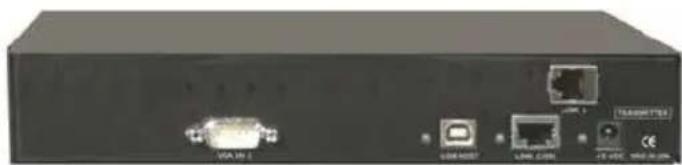
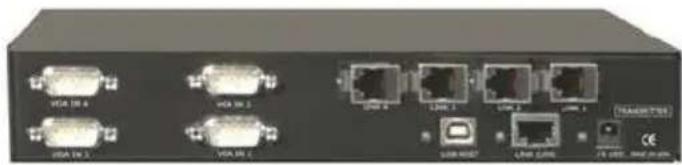
CrystalView USB2 Models
natural_image
Back view of a black electronic device showing ports and connectors (no readable text or symbols)Transmitter
natural_image
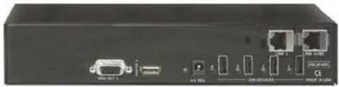
Back panel of a network device showing ports, connectors, and I/O ports (no readable text or symbols)Receiver
Single Video Model
natural_image
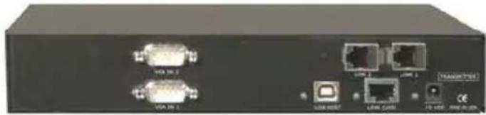
Front view of a black electronic device rear panel with ports and connectors (no visible text or symbols)Transmitter
natural_image
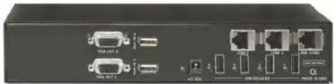
Front view of a network device rear panel showing ports, connectors, and indicator lights (no readable text or symbols)Receiver
Dual Video Model
natural_image
Front view of a network switch device showing multiple ports and connectors (no visible text or labels)Transmitter
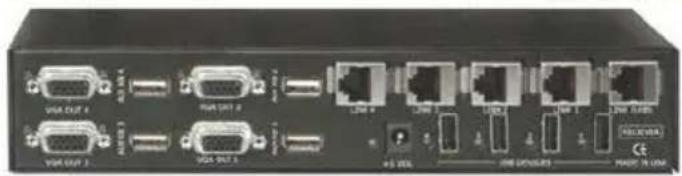
Receiver
Quad Video Model
Connectors
Transmitter
VGA IN HD15M
LINK x RJ45F
LINK USB RJ45F
LINK HOST USB TYPE B
Audio 3.5mm
POWER +5VDC
Receiver
VGA OUT HD15F
LINK x RJ45F
LINK USB RJ45F
USB DEVICES USB TYPE A
Audio 3.5mm
AUX / KB USB TYPE A
POWER +5VDC
INSTALLATION
Installation
Please refer to the safety section first before proceeding with any installation or configuration or the CrystalView USB2. It is recommended that the following installation procedure be followed to assure proper cable connections, power up sequencing, and accurate monitor DDC table information is obtained from the connected video monitors. Also all equipment should be powered off until all cabling is connected.
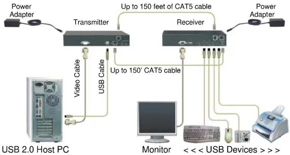
Figure 1 shows a typical configuration using the single video model. The dual and quad video models are installed and configured in the same manor with 2 or 4 PC video ports connected to the transmitter unit and 2 or 4 video monitors connected to the receiver unit.
flowchart
graph TD
    A["Power Adapter"] --> B["Transmitter"]
    B --> C["Receiver"]
    C --> D["Power Adapter"]
    B -->|Up to 150 feet of CAT5 cable| C
    B -->|Up to 150' CAT5 cable| E["Monitor"]
    E --> F["USB 2.0 Host PC"]
    B -->|Video Cable| G["USB Cable"]
    B -->|USB Cable| H["USB Device >> >"]
Figure 1 - Typical Configuration
NOTE: The maximum length of the Category 5 UTP cable must not exceed 50m. If Cat-5 patch cable is used, total length should not exceed 10m (EIA/TIA-568 specification).
NOTE: All references to Category 5 UTP solid core cable in this document represent the minimum requirement. Category 5E, Category 6 or better UTP or STP cable may be substituted.
NOTE: All units in the system should be tied to a common EARTH ground for proper operation
Transmitter installation
Refer to Figure 1 for transmitter installation
- Locate the transmitter near the host computer
- Connect the power adapter to the transmitter (Do not apply power)
- Connect a video extender cable from the transmitters HD15M connector to the host computers HD15F video output port and an audio cable (optional)
- Connect a USB cable from the Type B USB port on the transmitter to the Type A USB port on the host computer
NOTE: The host computer must be equipped with an EHCI host controller (USB 2.0). OHCI / UHCI (USB 1.1) host controllers are not supported. Video and USB cable lengths should not exceed 6.6'
Receiver Installation
Refer to Figure 1 for receiver installation
- Locate the receiver near the USB devices and video monitor
- Connect the power adapter to the transmitter (Do not apply power)
- Connect a video monitor to the receivers HD15F connector and audio cable (optional)
- Connect the USB devices to the USB ports on the receiver
Transmitter to Receiver installation (see note on page 5)
Refer to Figure 1 for transmitter to Receiver cable installation
- Connect up to feet of CAT5 cable from the transmitters LINK 1 RJ45 connector to the receivers LINK 1 RJ45 connector and from the transmitters LINK USB (1-4) RJ45 connectors to the receivers LINK USB (1-4) RJ45 connectors.
Connecting monitor(s) and USB Devices
- Connect a video monitor to the receivers HD15F connector
- Connect the USB devices to the USB ports on the receiver
Installing the dual and quad video models follows the same procedure. For the dual model, connect two video sources to the transmitter and two video monitors to the receiver. For the quad model connect four video sources to the transmitter and four video monitors to the receiver.
First time power up sequence
The first time the system is powered up or a monitor is changed, the below power up sequence should be followed
- Turn on all video monitors
- Apply power to the CrystalView USB2 Receiver
- Apply power to the CrystalView USB2 Transmitter
- Boot the PCs
- Turn on all USB devices
OPERATING PROCEDURES
Operating procedure
Operation of your system is no different than having your keyboard, monitor, mouse, speakers, and USB devices connected directly to a PC. The only difference is they can be up to 150 feet away. You can operate your system normally, programs can be executed, maintenance can be performed, and any operation normally performed can be done with no derogation in video quality and performance.
The video signal on all models can be fine tuned using simple keyboard commands. This is normally not needed but sometimes cable routing and patch panels can degrade the video signal. Next to each video in port (HD15M) on the receiver there is a USB Type A port labeled AUX/KBD. To execute the keyboard commands, connect a USB keyboard to the appropriate AUX/KBD port. The AUX/KBD port is for video adjustments only. Once the video has been adjusted perform the keyboard command Left Ctrl, Left Shift, k to save the information.
Keyboard Commands
| Command | Description |
| Left Ctrl, Left Shift, e: | Perform a cable length measurement |
| Left Ctrl, Left Shift, keyboard +: | Increase the video gain by 1 |
| Left Ctrl, Left Shift, keyboard -: | Decrease the video gain by 1. |
| Left Ctrl, Left Shift, keypad +: | increase the video equalization by 1 |
| Left Ctrl, Left Shift, keypad -: | Decrease the video equalization by 1 |
| Left Ctrl, Left Shift, k | Saves any changes made |
Table 1 - Keyboard Commands
LED Indicator Descriptions
| LED “ON” | |
| Transmitter “Host” LED | USB connection to computer OK |
| Transmitter “Link” LED | CAT5 link from receiver to transmitter OK |
| Transmitter “Power” LED | Power applied to transmitter OK |
| Receiver “Link” LED | CAT5 link from transmitter to receiver OK |
| Receiver “Device” LED | USB Device connections OK |
| Receiver “Power” LED | Power applied to receiver OK |
Table 2 - LED Indicators
TROUBLESHOOTING
Troubleshooting
The troubleshooting section is used as a guide to understanding the capabilities of the ViewLink CATx and for general troubleshooting. If you have any problems or questions concerning the installation, operation or usage of the ViewLink CATx that is not covered in this manual, please contact Rose Electronics for technical support.
• No video on the receiver monitor
- Check CATx connection at the receiver, transmitter, patch panels (if applicable)
- Check HD15 video connection at the receiver and transmitter
- Verify video is present at the video card output
- All LEDs on the receiver and transmitter are off
- Check power adapter connection to the units
- Check AC power input to the adapter
- The Link LED on the transmitter is on, the Host LED is off
- The transmitter is not connected to the computer
- The computer does not support USB 2.0 hubs
- Verify that the Device Manager recognizes the CrystalView USB2 as a generic USB hub
- USB device connected to the receiver but "Device" LED is off
- The USB device is not functioning properly
- The computer does not recognize the USB device
- The Device application software is not operating
Maintenance and Repair
This Unit does not contain any internal user-serviceable parts. In the event a Unit needs repair or maintenance, you must first obtain a Return Authorization (RA) number from Rose Electronics or an authorized repair center. This Return Authorization number must appear on the outside of the shipping container.
See Limited Warranty for more information.
When returning a Unit, it should be double-packed in the original container or equivalent, insured and shipped to:
Rose Electronics
Attn: RA
10707 Stancliff Road
Houston, Texas 77099 USA
Technical Support
If you are experiencing problems, or need assistance in setting up, configuring, or operating your CrystalView USB2, consult the appropriate sections of this manual. If, however, you require additional information or assistance, please contact the Rose Electronics Technical Support Department at:
Phone: (281) 933-7673
E-Mail: TechSupport@rose.com
Web: www.rose.com
Technical Support hours are from: 8:00 am to 6:00 pm CST (USA), Monday through Friday.
Please report any malfunctions in the operation of this Unit or any discrepancies in this manual to the Rose Electronics Technical Support Department.
Safety
The CrystalView USB2 USB and video extender has been tested for conformance to safety regulations and requirements, and has been certified for international use. Like all electronic equipment, the CrystalView USB2 should be used with care. To protect yourself from possible injury and to minimize the risk of damage to the Unit, read and follow these safety instructions.
■ Follow all instructions and warnings marked on this Unit.
■ Except where explained in this manual, do not attempt to service this Unit yourself.
■ Do not use this Unit near water.
■ Provide proper ventilation and air circulation.
- Keep power cord and connection cables clear of obstructions that might cause damage to them.
■ Use only power cords and connection cables designed for this Unit.
■ Use only a grounded (three-wire) electrical outlet.
■ Use only the power adapter provided with the CrystalView USB2.
- Keep objects that might damage this Unit and liquids that may spill, clear from this Unit. Liquids and foreign objects might come in contact with voltage points that could create a risk of fire or electrical shock.
■ Operate this Unit only when the cover is in place.
■ Do not use liquid or aerosol cleaners to clean this Unit. Always unplug this Unit from its electrical outlet before cleaning.
■ Unplug this Unit from the electrical outlet and refer servicing to a qualified service center if any of the following conditions occur:
- The power cord or connection cables are damaged or frayed.
■ The Unit has been exposed to any liquids.
- The Unit does not operate normally when all operating instructions have been followed.
- The Unit has been dropped or the case has been damaged.
- The Unit exhibits a distinct change in performance, indicating a need for service.
Appendix A. General Specifications
| Part Number | Description |
| CRK-1VH4U2TP-150 | Single Video / USB 2.0 |
| CRK-2VH4U2TP-150 | Dual Video / USB 2.0 |
| CRK-4VH4U2TP-150 | Quad Video / USB 2.0 |
| CRK-1VP4U2TP-150 | Single Video / USB 2.0 AUX – PS/2 |
| CRK-2VP4U2TP-150 | Dual Video / USB 2.0 AUX – PS/2 |
| CRK-4VP4U2TP-150 | Quad Video / USB 2.0 AUX – PS/2 |
| TFR-05D500FSUB-2.1 | 5V / 5A Universal Power Adapter |
W suffix = Automatic skew Adjustment option
/A1 suffix = uni-directional Audio option (single and dual models only)
/A2 suffix = bi-directional Audio option (single and dual models only)
| Dimensions | Width | Depth | Height | Weight |
| Transmitter (in / cm) | 8.8 / 22.4 | 5.6 / 14.2 | 1.75 / 4.45 | 3.3lb / 1.5kg |
| Receiver (in / cm) | 8.8 / 22.4 | 5.6 / 14.2 | 1.75 / 4.45 | 3.3lb / 1.5kg |
Distance 150 feet (50 m)
Resolution 1920 x 1200 @ 60 Hz
Compatibility SVGA, VGA, XGA, RGB
USB 1.1 (low and full speed) /
USB 2.0 (high-speed)
Levels: 0.7V p-p
Sync type Separate / composite TTL level
Receiver output 500ma per USB output port
power at each USB port
Audio Data:
Signal level 5V p-p
Impedance 47KΩ
Connectors 3.5mm stereo jack
Transmission 16 bit, 38.4KHz Digitized audio
Speakers Powered
Environment Operating Temp. 32°F-113°F (0°C-45°C)
Humidity 0% - 80% non-condensing

ROSE
ELECTRONICS
Server Management
