
PRV679 - Unspecified Panduit - Free user manual and instructions
Find the device manual for free PRV679 Panduit in PDF.

| Product Type | Vertical Cable Manager (PatchRunner) |
| Model | PRV679 |
| Width | 6 inches (152 mm) |
| Height | 79 inches (2006 mm) |
| Depth | Approximately 6 inches (152 mm) |
| Compatible Rack Width | Standard EIA 19-inch racks |
| Mounting Type | Center mounting between two racks |
| Material | Steel with powder coat finish |
| Color | Black (typical) |
| Weight | Approximately 15 lbs (6.8 kg) |
| Included Hardware | (6) 1/2-13 hex nuts, (6) 1/2-13x2.0 bolts, (12) washers, (4) spools, (2) 0.91 long 1/2-13 bolt spacers |
| Spool Type | Removable plastic spools for cable routing |
| Door Options | Dual hinged door or single hinged door (sold separately) |
| Finger Design | Removable fingers for easy cable access |
| Bend Radius Control | Maintains proper cable bend radius |
| Cleaning | PANDUIT recommends Simple Green all-purpose cleaner and lint-free cloth |
| Installation Torque | Tighten bolts to 120 lbs-in (13.6 Nm) |
| Application | Data center and network rack cable management |
Frequently Asked Questions - PRV679 Panduit
User questions about PRV679 Panduit
0 question about this device. Answer the ones you know or ask your own.
Ask a new question about this device
Download the instructions for your Unspecified in PDF format for free! Find your manual PRV679 - Panduit and take your electronic device back in hand. On this page are published all the documents necessary for the use of your device. PRV679 by Panduit.
USER MANUAL PRV679 Panduit
INSTALLATION INSTRUCTIONS CM293K
All PatchRunner Managers and Dual Hinged Doors are available in 96" tall versions
(PRV^96, PRVF^96, and PRD^96) \^ = 6.8, 10, 12, or 15 inch wide
6 inch and 12 inch wide PatchRunner Managers and Dual Hinged Doors are also available
79" tall versions (PRV679, PRVF679, PRD679, PRV1279, PRVF1279, PRV1279)
CONTENTS
(1) PATCHRUNNER Vertical Cable Manager
(6) 1/2-13 Hex Nuts
(6) 1/2-13x2.0" Bolts
(12) Washers for 1/2-13 bolts
(4) Spools
(2).91 long 1/2-13 Bolt Spacers
* Spools sold separately for PRV6 & PRVF6
6" Vertical Manager dimension shown in brackets [...]
8" Vertical Manager dimensions shown in parenthesis (...)
10" Vertical Manager dimensions shown in asterisk *...*
15 "Vertical Manager dimensions shown in brackets {...}
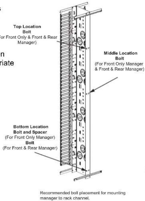
Center Mounting of a PATCHRUNNER on Standard EIA Rack
After the first rack is mounted to the floor with the appropriate hardware, Use Three 1/2-13x2.0" bolts (supplied with the vertical cable manager panels) to fasten the PATCHRUNNER Vertical Cable Manager to the rack. Next, mount the second rack to the other side of the PATCHRUNNER Vertical Cable Manager using the remaining 1/2-13x2.0" bolts. Then mount the second rack to the floor using the appropriate hardware.

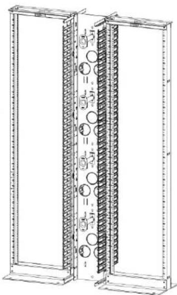
natural_image
Technical line drawing of a dual-panel server rack unit with circular components and mounting brackets (no text or symbols)Note: Tighten bolts to 120 lbs.-in.
INSTALLATION OF SPOOLS
Step 1
Align buttons with mounting leg slot

Step 2
Push buttons through backbone until mounting face is flush with backbone.

natural_image
Technical line drawing of a mechanical assembly with no visible text or symbols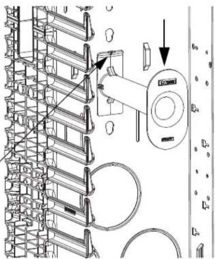
natural_image
Technical line drawing of a mechanical assembly with no visible text or symbolsStep 3
Apply downward pressure until plastic spool clicks into place.
Removal/Replacement
Step 4
Pull back on angled flange while applying upward pressure
Step 5
Repeat steps 1-3
DUAL HINGED DOOR BRACKET INSTALLATION
Attach cross braces with #10-32 screws to door bracket as shown in picture below. Align angled notch on cross brace with angled notch on door bracket when tightening screws.

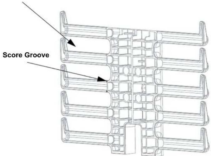
FINGER REMOVAL
Apply inward pressure at finger ends to remove finger
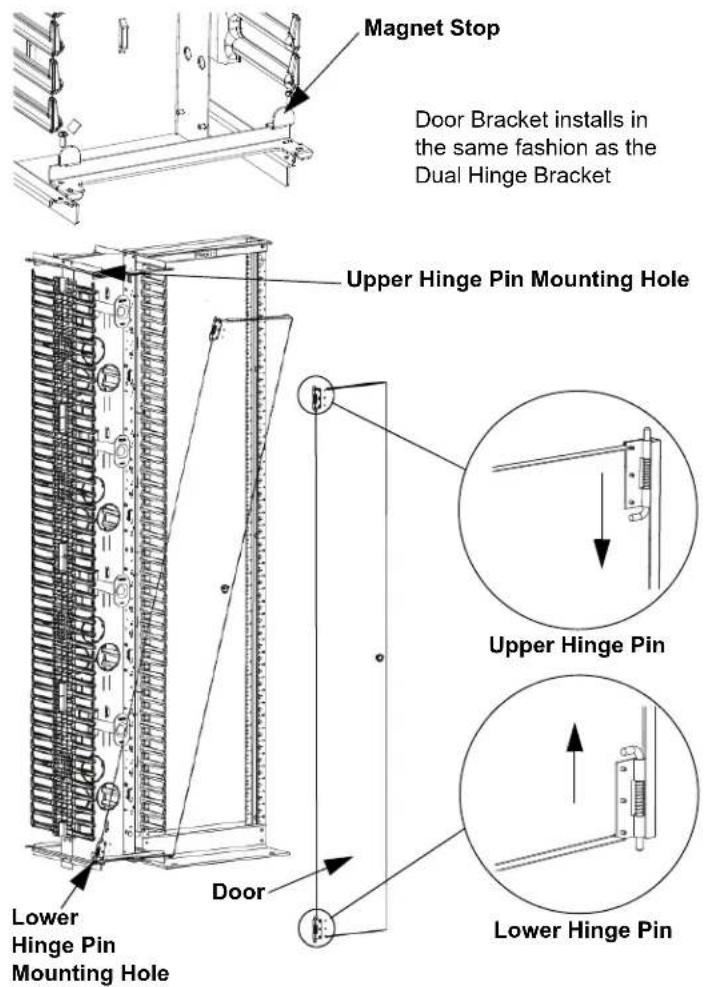
DUAL HINGED DOOR INSTALLATION
Align lower pins with lower hinge pin mounting holes. Squeeze release knobs together, then align upper door pins with upper hinge pin mounting holes. Release pressure on the release knobs to set door in place.
Upper Hinge Pin Mounting Hole

Note: For cleaning PANDUIT recommends using 'SIMPLE GREEN' all purpose cleaner (or local equivalent) and a lint free cloth
SINGLE HINGED DOOR INSTALLATION
Align lower door pin with lower hinge pin mounting hole. Then align upper door pin with upper hinge pin mounting hole pull down on pin and insert it into the mounting hole. Door can be hinged to the right or left by reversing top and bottom.
Note: For cleaning PANDUIT recommends using 'SIMPLE GREEN' all purpose cleaner (or local equivalent) and a lint free cloth
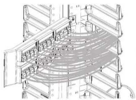
ROUTING CABLE
Patch Panels Through
PATCHRUNNER Vertical Cable Manager
Route cables through fingers of PATCH-RUNNER Vertical Manager maintaining cable bend radii. Use a slot on the PATCH-RUNNER Vertical Cable Manager that is the same height as the patch panel. Proper routing for angled patch panel and flat patch panel shown below.
natural_image
Technical line drawing of a multi-level rack or server rack structure with no visible text or symbolsAngled Patch Panel Detail

natural_image
Technical line drawing of a multi-level rack structure with mesh pattern (no text or symbols)Flat Patch Panel Detail
INSTALLATION INSTRUCTIONS CM293K
EXAMPLES OF ROUTING PATCH CORD SLACK
Note: For additional information reference CD routing guidelines
SA-RKCD01

For instructions in Local Languages and Technical Support:
www.panduit.com/resources/install_maintain.asp


- INSTALLATION INSTRUCTIONS CM293K
- CONTENTS
- Center Mounting of a PATCHRUNNER on Standard EIA Rack
- INSTALLATION OF SPOOLS
- Step 1
- Step 2
- Step 3
- Removal/Replacement
- Step 4
- Step 5
- DUAL HINGED DOOR BRACKET INSTALLATION
- FINGER REMOVAL
- DUAL HINGED DOOR INSTALLATION
- SINGLE HINGED DOOR INSTALLATION
- ROUTING CABLE
- Patch Panels Through
- PATCHRUNNER Vertical Cable Manager
Brand : Panduit
Model : PRV679
Category : Unspecified