DX-RTVM112 - Wall mount Dynex - Free user manual and instructions
Find the device manual for free DX-RTVM112 Dynex in PDF.

User questions about DX-RTVM112 Dynex
0 question about this device. Answer the ones you know or ask your own.
Ask a new question about this device
Download the instructions for your Wall mount in PDF format for free! Find your manual DX-RTVM112 - Dynex and take your electronic device back in hand. On this page are published all the documents necessary for the use of your device. DX-RTVM112 by Dynex.
USER MANUAL DX-RTVM112 Dynex
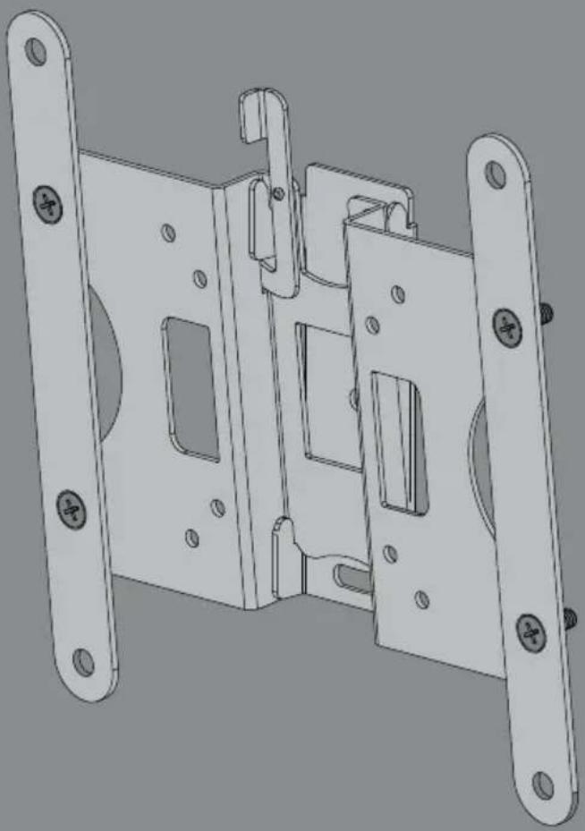
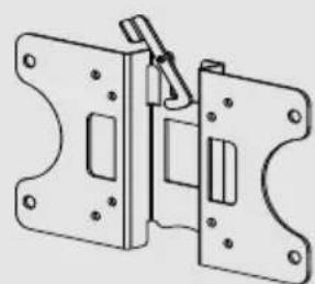
Low-Profile TV Wall Mount
natural_image
Technical line drawing of a mechanical latch or bracket assembly (no text or symbols)
For either wood-stud or concrete wall installations
Safety information and specifications .2
Tools needed....3
Package contents 4
Installation instructions....5
Safety information and specifications

natural_image
Gray triangular warning symbol with black exclamation mark (no text or numbers)IMPORTANT
SAFETY
INSTRUCTIONS - SAVE THESE
INSTRUCTIONS
CAUTION: Do
not use this
product for any purpose not explicitly specified by Dynex.
Improper installation may cause property damage or personal injury. If you do not understand these directions, or have doubts about the safety of the installation, contact Customer Service or call a qualified contractor. Dynex is not responsible for damage or injury caused by incorrect installation or use.
The weight of your TV must not exceed 35
Ibs. (15.8 kg). The wall must be capable of supporting five times the weight of your TV and wall mount combined.
This product contains small items that could be a choking hazard if swallowed. Keep these items away from young children!
Maximum TV weight: 35 lbs.
(15.8 kg)
Screen size: 13 in. to 36 in. diagonal
Overall dimensions (H × W × D):
9.5 x 2.5 x 9.25 in.
(24.1 × 6.35 × 23.5 cm)
Wall-mount weight: 2.115 lb.
(0.959 kg)
We're here for you
www.dynexproducts.com
For customer service, call:
1-800-305-2204 (U.S. and Canada) or
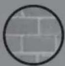
Tilt range
text_image
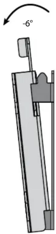
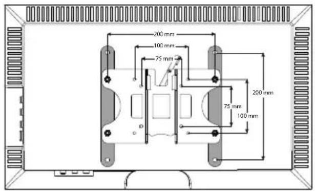
-6°Compatible VESA patterns
text_image
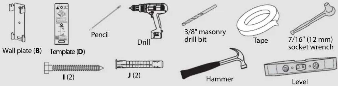
200 mm 100 mm 75 mm 200 mm 75 mm 100 mmTools needed
You will need the following tools to assemble your new TV wall mount:
natural_image
Simple line drawing of a pencil with no text or symbolsPencil
natural_image
Line drawing of a handheld electric drill (no text or symbols)Drill
Level
natural_image
Simple line drawing of a remote control device with no text or symbolsEdge-to-edge stud finder
natural_image
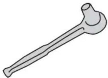
Illustration of a bone-shaped tool (no text or symbols)Socket wrench with 7/16" (12 mm) socket or adjustable wrench
natural_image
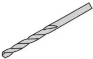
Illustration of a twist drill bit with no text or symbols1/8" (3 mm) wood drill bit for wood stud wall
OR
3/8" (10 mm) masonry drill bit (concrete only)
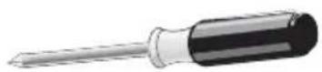
Phillips screwdriver
natural_image
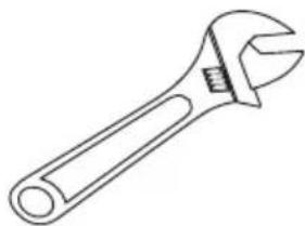
Line drawing of an adjustable wrench (no text or symbols)Adjustable wrench
natural_image
Simple line drawing of a hammer (no text or symbols)Hammer
natural_image
Illustration of a tape measure with a ruler, no text or symbols presentMeasuring tape
natural_image
Simple line drawing of a ring or tape (no text or symbols)Tape
Package contents
Make sure that you have all of the hardware necessary to assemble your new TV wall mount:
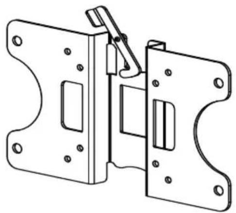
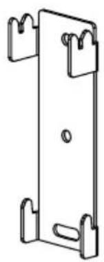
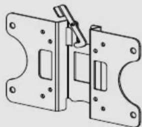
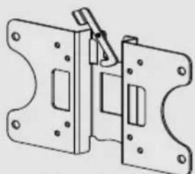
A TV Bracket (1)
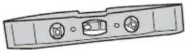
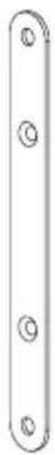
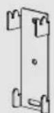
B Wall Plate (1)
C Bracket Extensions (2)
D Wall mount template (1)
A
natural_image
Technical line drawing of a mechanical latch or bracket assembly (no text or symbols)B
natural_image
Simple line drawing of a rectangular metal bracket with mounting holes (no text or symbols)C
D
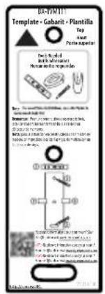
text_image
B-PONTY Template - Gabavit - Plantilla Top Pertapegents Dial Applicable Newer for the 12th edition Newer for the 12th edition 100% 100% 100% 100% 100% 100% 100% 100% 100% 100% 100% 100% 100% 100% 100% 100% 100% 100% 100% 100% 100% 100% 100% 100% 100% 100%TV Hardware Bag
| Label | Hardware | Qty. | |
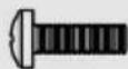
| E | 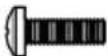 | M4 × 12 mmscrew | 4 |
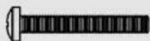
| F | 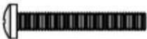 | M4 × 35 mmscrew | 4 |
| G |  | M4 washer | 4 |
| H | 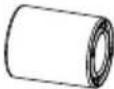 | M4 spacers | 4 |
| Label | Hardware | Qty. |
| I | 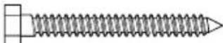 1/4'' × 2 3/4'' lag bolt 1/4'' × 2 3/4'' lag bolt | 2 |
| J | 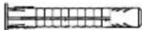 Concrete anchor Concrete anchor | 2 |
| K |  M6 x 14 mm screw M6 x 14 mm screw | 4 |
| L | M6 Nut | 4 |
line
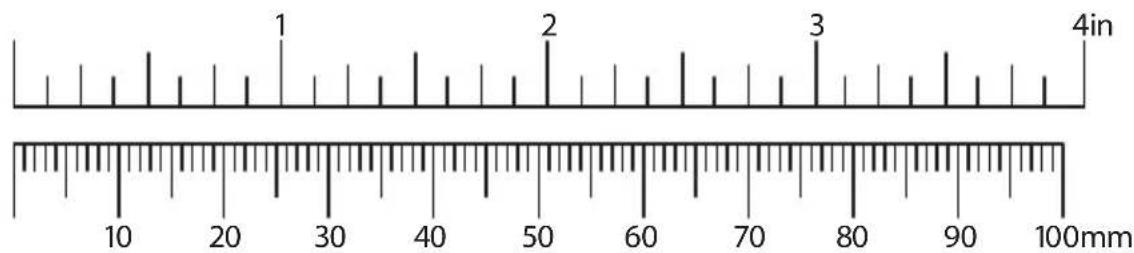
| Point | Value | |-------|-------| | 1 | 25 | | 2 | 50 | | 3 | 75 |Installation instructions
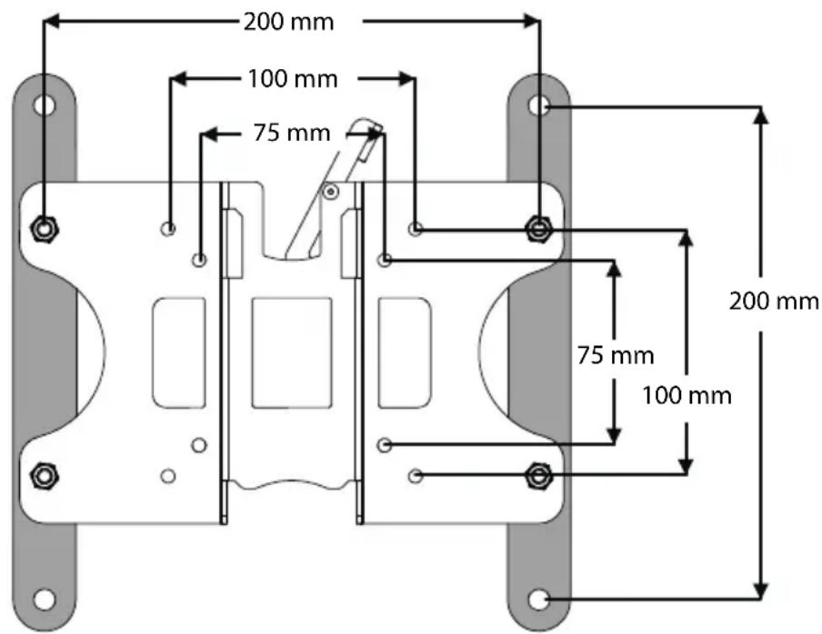
STEP 1 - Determining the hole pattern on your TV
1 Carefully place your TV screen face down on a cushioned, clean surface to protect the screen from damage and scratches.
2 If your TV has a table top stand attached, remove the stand. See the documentation that came with your TV for instructions.
3 Measure the distance between the mounting holes on the back of your TV.
4 If your TV has a 200 x 200 mm hole pattern, you must install the bracket extensions (C) onto the TV bracket (A).
text_image
200 mm 100 mm 75 mm 200 mm 75 mm 100 mm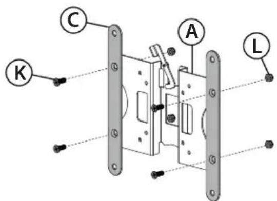
text_image
C A K L5 If you need to install the extension brackets (C), install them on the front (flat side) of the TV bracket (A) with four M6 x 14 mm screws (K) and four M6 nuts (L), as shown, using the phillips screwdriver and the adjustable wrench.
You'll need
K (4)
L (4)

Adjustable wrench
C (2)
natural_image
Technical line drawing of a mechanical clamp or bracket assembly (no text or symbols)TV bracket (A)
STEP 2 - Determine whether your TV has a flat, irregular, or obstructed back
1 Temporarily lay the TV bracket (A) and adapters (C), if necessary, on the back of your TV.
2 Align the screw holes in the TV bracket with the mounting screw holes on your TV.
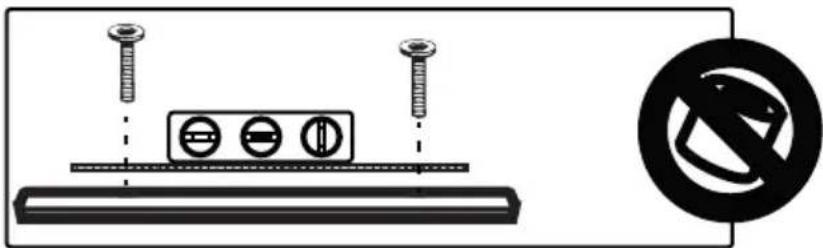
3 Identify which type of back your TV may have:
- Flat back: The bracket and adapters (if necessary) lay flush against the back of your TV and does not block any jacks. You do not need spacers when assembling the wall mount.
text_image
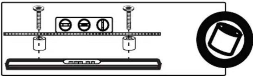
Diagram showing screw installation with three circular components and a no-smoking symbol- Obstructed back: The bracket and adapters (if necessary) block one or more of the jacks on the back of your TV. You will need spacers when assembling the wall mount.
natural_image
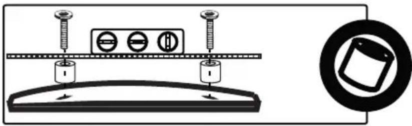
Diagram showing screw installation components including a battery, screw holder, and tray with a magnified inset of a device (no text or symbols)- Irregularly-shaped back: There is a gap between the bracket and adapters (if necessary) and some part of the back of your TV. You will need spacers when assembling the wall mount.
text_image
Diagram showing screw installation setup with three circular components and a magnified view of a mechanical component.4 Remove the TV bracket (A) and adapters (C).
STEP 3 - Select screws and spacers
1 Select the hardware for your TV (screws and spacers). A limited number of TVs come with mounting hardware included. (If there are screws that came with the TV, they are almost always in the holes on the back of the TV.)
Select one of the following types of screws:
M4 × 12 mm screws (E) for a flat back TV.
M4 × 35 mm screws (F) for an irregular or obstructed TV back.
For an irregular or obstructed TV back, use the following spacers:
M4 spacers (H)
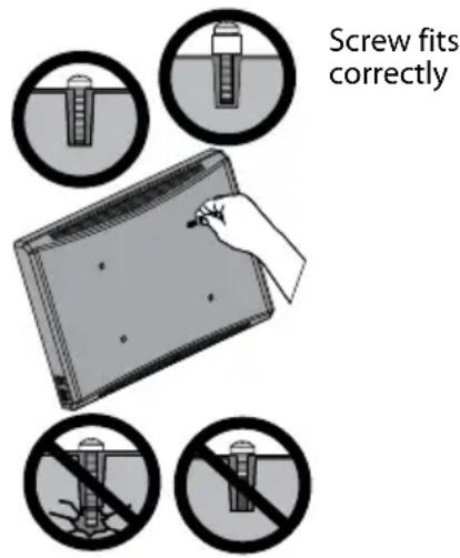
text_image
Screw fits correctlyScrew is too long
Screw is too short

CAUTION: To avoid potential personal injuries and property damage, make sure that there are adequate threads to secure the brackets to your TV. If you encounter resistance, stop immediately and contact customer service. Use the shortest screw and spacer combination to accommodate your TV. Using hardware that is too long may damage your TV. However, using a screw that is too short may cause your TV to fall from the mount.
2 Remove the screws.
3 For a flat back TV, go to "STEP 4 - Option 1: Attaching the mounting hardware to TVs with a flat back" on page 8.
-OR-
For an irregular or obstructed back, go to "STEP 4 - Option 2: Attaching the mounting hardware to TVs with irregular or obstructed backs" on page 9.
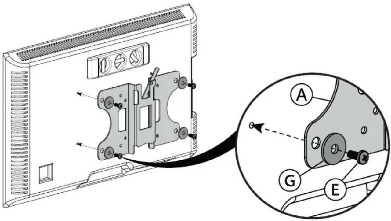
STEP 4 - Option 1: Attaching the mounting hardware to TVs with a flat back
1 Align the TV bracket (A) with the screw holes on the back of the TV.
2 Install washers (G), and screws (E) into the holes in the back of the TV.
3 Tighten the screws until they are snug against the TV bracket. Do not over tighten.
text_image
Technical diagram of a device rear panel with labeled components and an inset view showing internal structure with labeled parts A, G, and E.You'll need
Screws
E (4)
Washers
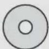
G (4)
Phillips screwdriver
natural_image
Technical line drawing of a mechanical clamp or bracket assembly (no text or symbols)TV bracket (A)
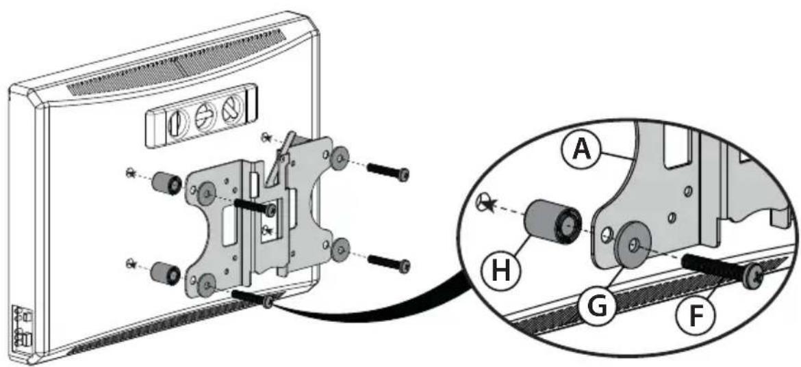
STEP 4 - Option 2: Attaching the mounting hardware to TVs with irregular or obstructed backs
1 Align the TV bracket (A) with the screw holes on the back of the TV.
2 Place spacers (H) behind the TV bracket and the washers (G) over the holes in the TV bracket, then insert the screws (F) through the washers, TV bracket, and spacers.
3 Tighten the screws until they are snug against the TV bracket. Do not over tighten.
text_image
Technical diagram showing mechanical assembly with labeled parts A, H, G, and F, including a close-up view of the component.You'll need
Screws
F (4)
Washers
G (4)
Spacers
H (4)
Phillips screwdriver
natural_image
Technical line drawing of a mechanical bracket or locking mechanism (no text or symbols)TV bracket (A)
STEP 5 - Determine wall-mount location
Notes:
- For more detailed information on determining where to drill your holes, visit our online height-finder at: http://mf1.bestbuy.selectionassistant.com/index.php/heightfinder
- Your TV should be high enough so your eyes are level with the middle of the screen. Normally, the center of your TV should be 40 to 60 inches (100 to 150 cm) above the floor.
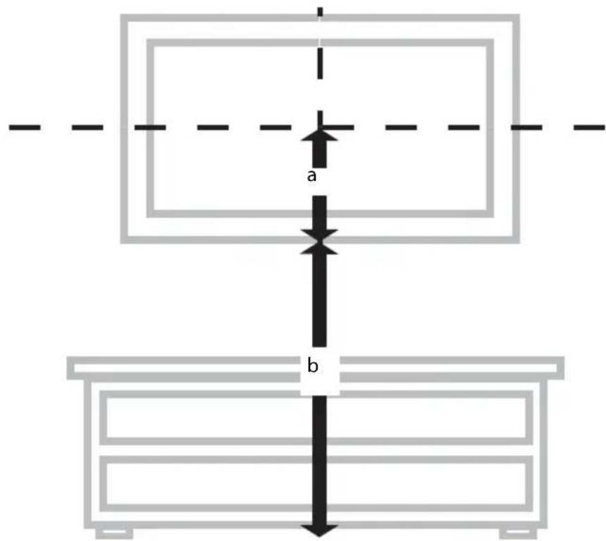
The center of your TV will match the center of the wall plate (B). Before you drill holes in the wall:
1 Measure the distance from the bottom of your TV to the middle (half of the height of the TV). This is measurement a.
2 Measure the distance from the floor to where you want the bottom of the TV to be placed on the wall. Keep in mind that the bottom of the TV should be placed above any furniture (such as entertainment centers or TV stands). The TV should also be above items placed on top of the furniture (like a Blu-ray player or cable box). This measurement is b.
3 Add a + b. The total measurement is the height where you want the center of the wall plate (B) to be on the wall.
4 Use a pencil to mark this spot on the wall.
text_image
a b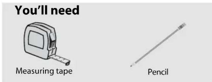
text_image
You'll need Measuring tape PencilSTEP 6 - Option 1: Installing on a wood stud\* wall
Note: Any drywall covering the wall must not exceed 5/8" (16 mm).
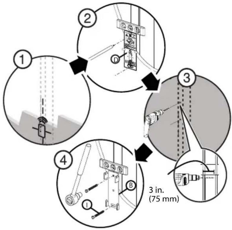
1 Locate the stud. Verify the center of the stud with an edge-to-edge stud finder.
2 Align the wall plate template (D) at the height you determined in the previous step and make sure that it is level. Tape the wall plate template in position, then use a pencil to mark the lag bolt hole locations (2).
3 Drill pilot holes to a depth of 3 in. (75 mm) using a 1/8" (3 mm) wood drill bit. Remove the wall plate template.
4 Align the wall plate (B) with the pilot holes, insert the lag bolts (I) through the holes in the wall plate, then tighten the lag bolts only until they are firm against the arm assembly.

CAUTION: Avoid potential injuries or property damage! DO NOT over-tighten the lag bolts (I).
* Minimum wood stud size: common 2 x 4 in. (51 x 102 mm) nominal 11/2 x 31/2 in. (38 x 89 mm).
flowchart
graph TD
    A["Step 1: Initial setup with vertical bars and sensors"] --> B["Step 2: Component assembly with bracket and connection points"]
    B --> C["Step 3: Structural inspection with workers and tools"]
    C --> D["Step 4: Measurement device with labeled parts 1, B, and 3 in. (75 mm)"]
You'll need
Wall plate (B)
Edge-to edge
stud finder
Template (D)
Pencil
Drill
Tape
1/8" wood drill bit
7/16" (12mm) socket wrench
Level
I(2)
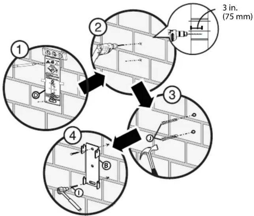
STEP 6 - Option 2: Installing on a solid concrete\* or concrete block wall

CAUTION: To prevent property damage or personal injury, never drill into mortar between blocks. Mount the wall plate directly onto the concrete surface.
1 Align the wall plate template (D) at the height you determined in the previous step and make sure that it is level. Tape the wall plate template in position, then use a pencil to mark the lag bolt hole locations (2).
2 Drill pilot holes to a depth of 3 in. (75 mm) using a 3/8 in. (10 mm) diameter masonry drill bit. Remove the wall plate template.
3 Insert the concrete wall anchors (J) into the pilot holes and use a hammer to make sure the anchors are flush with the concrete surface.
4 Align the wall plate (B) with the anchors, insert the lag bolts (I) through the holes in the wall plate, then tighten the lag bolts only until they are firm against the wall plate.

CAUTION: Avoid potential injuries or property damage! DO NOT over-tighten the lag bolts (I).
* Minimum solid concrete thickness: 8 in. (203 mm)
* Minimum concrete block size: 8 x 8 x 16 in. (203 x 203 x 406 mm)
flowchart
graph TD
    A["Step 1: Wall wall installation"] --> B["Step 2: Tool positioning"]
    B --> C["Step 3: Tool positioning with 3 inches (75 mm)"]
    C --> D["Step 4: Tool positioning with 3 inches (75 mm)"]
    D --> E["End"]
You'll need
text_image
Wall plate (B) Template (D) Pencil Drill 3/8" masonry drill bit Tape 7/16" (12 mm) socket wrench I (2) J (2) Hammer LevelSTEP 7 - Mounting the TV to the wall plate
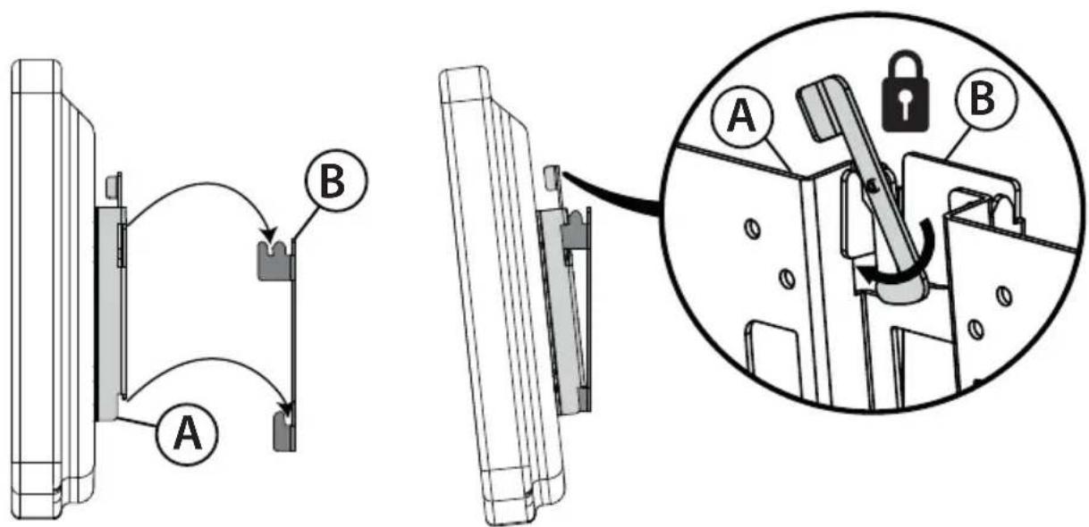
1 Place the TV bracket (A) into the slotted flanges of the wall plate (B). The TV can be mounted either (1) vertically, or (2) with a 6^ tilt.
2 Lock the TV and bracket assembly to the wall plate by rotating the lock into the flange slot.

HEAVY! You will need assistance with this step.
For a vertical mount, attach the TV bracket to the flange that is closest to the wall plate.
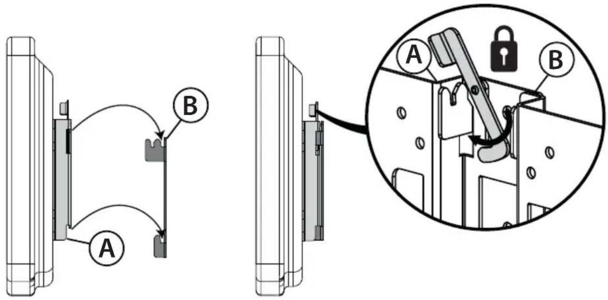
text_image
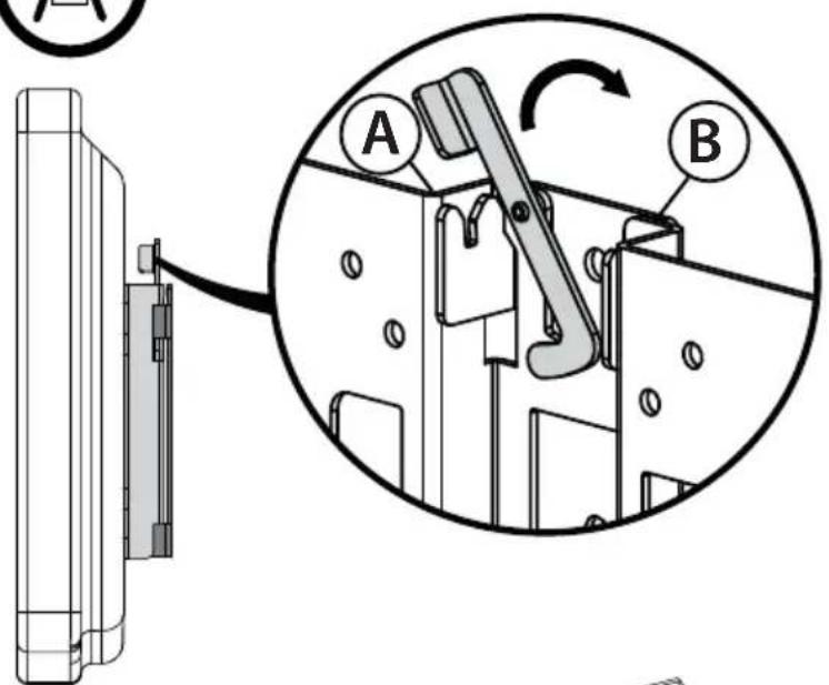
Technical diagram showing mechanical assembly with labeled components A and B, including a magnified inset of a lock mechanism.For a tilt mount attach the TV bracket to the flange that is farthest from the wall plate.
text_image
Technical diagram showing mechanical assembly with labeled components A and B, including a magnified inset of a lock mechanism.STEP 8 - Removing the TV from the wall plate and disassembling the wall mount
1 Unlock the TV and bracket assembly from the wall plate by rotating the lock out of the flange slot.
2 Lift the TV bracket (A) from the slotted flanges of the wall plate (B) and place it on a cushioned, clean surface to protect the screen from damage and scratches.
3 Using a Phillips screwdriver, remove the screws from the back of your TV, then remove the TV bracket.
4 Using a 7/16" or 12 mm socket wrench, remove the lag bolts from the wall, then remove the wall plate.

HEAVY! You will need assistance with this step.
text_image
Technical diagram showing a mechanical assembly with labeled parts A and B, including a magnified inset view.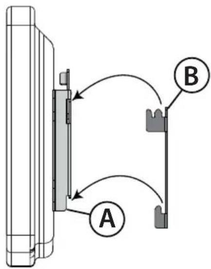
text_image
A B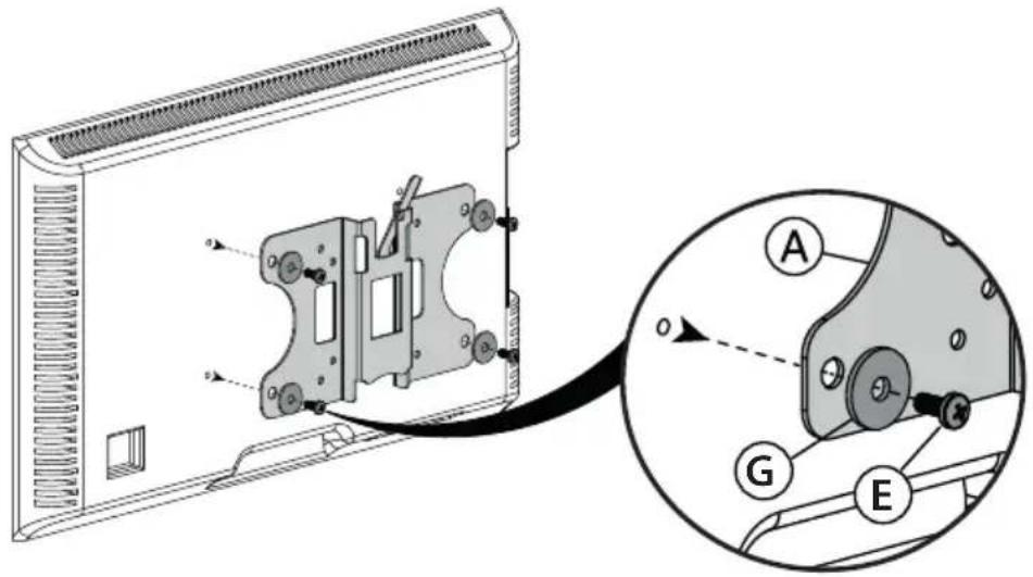
text_image
Technical diagram showing a device with labeled components (A, G, E) and an inset view of the internal structure.You'll need
Phillips screwdriver
7/16" (12 mm) socket wrench
DYNEX™
www.dynexproducts.com 1-800-305-2204 (U.S. and Canada) or 01-800-926-3020 (Mexico)
Distributed by Best Buy Purchasing, LLC
7601 Penn Ave. South, Richfield, MN 55423 U.S.A.
© 2013 BBY Solutions, Inc. All rights reserved.
DYNEX is a trademark of BBY Solutions, Inc. Registered in some countries. All other products and
brand names are trademarks of their respective owners.
6907-00205100