
PDSP-1 - CD Player PIONEER - Free user manual and instructions
Find the device manual for free PDSP-1 PIONEER in PDF.

| Product type | Digital Sound Projector |
| Brand | Pioneer |
| Model | PDSP-1 |
| Dimensions (W x H x D) | 963 x 640 x 146 mm |
| Weight | 50 kg (with front grille) |
| Power supply | AC 120 V, 60 Hz (US model) / AC 100-240 V, 50/60 Hz (European model) |
| Power consumption | 750 W (operating), 3 W (standby) |
| Number of speakers | 254 individual speaker units |
| Rated output power | 2 W x 254 channels (80 Hz - 20 kHz) |
| Frequency response | 80 Hz - 20 kHz, ±3 dB |
| Supported audio formats | Dolby Digital, Dolby Pro Logic II, DTS |
| Audio inputs | 1x digital coaxial, 3x digital optical, 1x analog (with S-Video/composite video) |
| Audio outputs | 1x digital optical, 2x subwoofer (RCA jacks) |
| Video outputs | Composite and S-Video (monitor) |
| Remote control | Rechargeable LCD touchscreen with docking station |
| Main features | Sound beam control technology, multi-channel playback without multiple speakers, surround modes (PLII Movie/Music/Pro Logic), room acoustic settings (8 memories), lip sync compensation, bass/treble adjustment, subwoofer output |
| Maintenance and cleaning | Wipe with a soft, dry cloth. For stubborn dirt, use a soft cloth dampened with a mild detergent solution, then wipe with a dry cloth. Do not use thinners, benzene, insecticides, or other chemicals. |
| Safety | Do not expose to rain or moisture. Do not obstruct ventilation openings. Use only the supplied power cord. Disconnect during thunderstorms or prolonged non-use. Contact a qualified professional for installation and calibration. |
| Installation | Must be installed and calibrated by a trained professional technician. Minimum ventilation space of 3 cm at the rear. Ambient temperature: +5°C to +35°C, humidity <85% RH. |
| Included accessories | Remote control, charger, power adapter, power cord, front grille, instruction manual |
Frequently Asked Questions - PDSP-1 PIONEER
User questions about PDSP-1 PIONEER
0 question about this device. Answer the ones you know or ask your own.
Ask a new question about this device
Download the instructions for your CD Player in PDF format for free! Find your manual PDSP-1 - PIONEER and take your electronic device back in hand. On this page are published all the documents necessary for the use of your device. PDSP-1 by PIONEER.
USER MANUAL PDSP-1 PIONEER
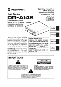
DIGITAL SOUND PROJECTOR
PDSP-1
Thank you for buying this Pioneer product.
Please read through these operating instructions so you will know how to operate your model properly. After you have finished reading the instructions, put them away in a safe place for future reference.
WARNING: THE APPARATUS IS NOT WATERPROOF, TO PREVENT FIRE OR SHOCK HAZARD, DO NOT EXPOSE THIS APPARATUS TO RAIN OR MOISTURE AND DO NOT PUT ANY WATER SOURCE NEAR THIS APPARATUS, SUCH AS VASE, FLOWER POT, COSMETICS CONTAINER AND MEDICINE BOTTLE ETC. H001BEn
Replacement and mounting of an AC plug on the power supply cord of this unit should be performed only by qualified service personnel.
IMPORTANT
FOR USE IN THE UNITED KING
DOM.
The wires in this mains lead are coloured in accor
dance with the following code
Green and Yellow : Earth
Blue : Neutral
Brown :Live
If the plug provided is unsuitable for your socket outlets, the plug must be cut off and a suitable plug fitted.
The cut-off plug should be disposed of and must not be inserted into any 13 amp socket as this can result in electric shock. The plug or adaptor or the distribution panel should be provided with 5 A fuse. As the colours of the wires in the mains lead of this appliance may not correspond with coloured markings identifying the terminals in your plug, proceed as follows;
The wire which is coloured green and yellow must be connected to the terminal in the plug which is marked with the letter E or by the earth symbol ,or coloured green or green and yellow.
The wire which is coloured blue must be connected to the terminal which is marked with the letter N or coloured black.
The wire which is coloured brown must be connected to the terminal which is marked with the letter L or coloured red.
NOTE
After replacing or changing a fuse, the fuse cover in the plug must be replaced with a fuse cover which corresponds to the colour of the insert in the base of the plug or the word that is embossed on the base of the plug, and the appliance must not be used without a fuse cover. If lost replacement fuse covers can be obtained from: your dealer.
Only 5 A fuses approved by B.S.I. or A.S.T.A to B.S. 1362 should be used. H004BEn
This product complies with the Low Voltage Directive (73/23/ EEC, amended by 93/68/EEC), EMC Directives (89/336/EEC, amended by 92/31/EEC and 93/68/EEC). H015AEn
WARNING: BEFORE PLugging IN THE UNIT FOR THE FIRST TIME, READ THE FOLLOWING SECTION CAREFULLY. THE VOLTAGE OF THE AVAILABLE POWER SUPPLY DIFFERS ACCORDING TO COUNTRY OR REGION. BE SURE THAT THE POWER SUPPLY VOLTAGE OF THE AREA WHERE THIS UNIT WILL BE USED MEETS THE REQUIRED VOLTAGE (E.G., 230V OR 120V) WRITTEN ON THE REAR PANEL. H041A En
INSTALLATION
Note: Reference is made to ISO/IEC Guide 37 [12].
VENTILATION:
- When placing this unit with using optional stand or wall-mount kit, make sure to leave space around the unit for ventilation to improve heat dispersal at least 3cm at the rear. If not enough space is provided between the unit and walls or other furniture, heat will build up inside, interfering with performance and/or causing malfunctions.
- Do not cover the unit with fabric or other covering. Anything that blocks ventilation will cause the internal temperature to rise, which may lead to breakdown or fire hazard.
The rear of unit may become hot while in use, please take care around it.
WARNING: Slot and openings in the cabinet are provided for ventilation and to ensure reliable operation of the product and to protect it from overheating, to prevent fire hazard, the openings should never be blocked and covered with items, such as newspapers, table-cloths, curtains, etc. Also do not put the apparatus on the thick carpet, bed, sofa, or fabric having a thick pile.
WARNING: NO NAKED FLAME SOURCES, SUCH AS LIGHTED CANDLE, SHOULD BE PLACED ON THE APPARATUS. IF NAKED FLAME SOURCES ACCIDENTALLY FALL DOWN, FIRE SPREAD OVER THE APPARATUS THEN MAY CAUSE FIRE.
H044 En
Operating Environment
H045 En
Operating environment temperature and humidity:
+5°C - +35°C (+41°F - +95°F); less than 85%RH (cooling vents not blocked)
Do not install in locations exposed to strong sunlight, strong artificial light, high humidity or locations that have poor ventilation.
Note: The unit must be installed in such a way that it is possible to easily disconnect the mains plug.
CAUTION: To prevent injury, this apparatus must be securely attached to the appropriate Pioneer stands (model numbers B-PDSP-H, B-PDSP-L or BPDSP-W) in accordance with the installation instructions. Use with other apparatus is capable of resulting in instability causing possible injury.
WARNING: THIS PRODUCT EQUIPPED WITH A THREE-WIRE GROUNDING TYPE PLUG, A PLUG HAVING A THIRD (GROUNDING) PIN, IT WILL ONLY FIT INTO A GROUNDING TYPE POWER OUTLET. THIS IS A SAFETY FEATURE. IF YOU ARE UNABLE TO INSERT THE PLUG INTO THE OUTLET, CONTACT YOUR ELECTRICIAN TO REPLACE YOUR OBSOLETE OUTLET. DO NOT DEFEAT THE SAFETY PURPOSE OF THE GROUNDING TYPE PLUG. H043 En
CAUTION: To disconnect the unit from the mains supply unplug the mains plug. Install the unit in such a way that it is easy to disconnect the mains plug in case of an accident. The mains plug of the unit should be unplugged from the wall socket when left unused for a long period of time.
This product is for general household purposes. Any failure due to use for other than household purposes (such as long-term use for business purposes in a restaurant or use in a car or ship) and which requires repair will be charged for even during the warranty period. K041_En
IMPORTANT

The lightning flash with arrowhead symbol, within an equilateral triangle, is intended to alert the user to the presence of uninsulated 'dangerous voltage' within the product's enclosure that may be of sufficient magnitude to constitute a risk of electric shock to persons.
CAUTION
RISK OF ELECTRIC SHOCK DO NOT OPEN
CAUTION:
TO PREVENT THE RISK OF ELECTRIC SHOCK,DO NOT REMOVE COVER (OR BACK).NO USER-SERVICEABLE PARTS INSIDE. REFER SERVICING TO QUALIFIED SERVICE PERSONNEL.

The exclamation point within an equilateral triangle is intended to alert the user to the presence of important operating and maintenance (servicing) instructions in the literature accompanying the appliance.
IMPORTANT SAFETY INSTRUCTIONS
H003 En
1) Read these instructions.
2) Keep these instructions.
3) Heed all warnings.
4) Follow all instructions.
5) Do not use this apparatus near water.
6) Clean only with dry cloth.
7) Do not block any ventilation openings. Install in accordance with the manufacturer's instructions.
8) Do not install near any heat sources such as radiators, heat registers, stoves, or other apparatus (including amplifiers) that produce heat.
9) Do not defeat the safety purpose of the polarized or grounding-type plug. A polarized plug has two blades with one wider than the other. A grounding type plug has two blades and a third grounding prong. The wide blade or the third prong are provided for your safety. If the provided plug does not fit into your outlet, consult an electrician for replacement of the obsolete outlet.
10) Protect the power cord from being walked on or pinched particularly at plugs, convenience receptacles, and the point where they exit from the apparatus.
11) Only use attachments/accessories specified by the manufacturer.
12) Use only with the cart, stand, tripod, bracket, or table specified by the manufacturer, or sold with the apparatus. When a cart is used, use caution when moving the cart/apparatus combination to avoid injury from tip-over.

13) Unplug this apparatus during lightning storms or when unused for long periods of time.
14) Refer all servicing to qualified service personnel. Servicing is required when the apparatus has been damaged in any way, such as power-supply cord or plug is damaged, liquid has been spilled or objects have fallen into the apparatus, the apparatus has been exposed to rain or moisture, does not operate normally, or has been dropped.
[For U.S. model]
IMPORTANT NOTICE
The serial number for this equipment is located in the rear panel. Please write this serial number on your enclosed warranty card and keep it in a secure area. This is for your security. H006AEn
WARNING: Handling the cord on this product or cords associated with accessories sold with the product will expose you to lead, a chemical known to the State of California and other governmental entities to cause cancer and birth defects or other reproductive harm.
Wash hands after handling.
POWER-CORD CAUTION
S002 En
Handle the power cord by the plug. Do not pull out the plug by tugging the cord and never touch the power cord when your hands are wet as this could cause a short circuit or electric shock. Do not place the unit, a piece of furniture, etc., on the power cord, or pinch the cord. Never make a knot in the cord or tie it with other cords. The power cords should be routed such that they are not likely to be stepped on. A damaged power cord can cause a fire or give you an electrical shock. Check the power cord once in a while. When you find it damaged, ask your nearest PIONEER authorized service center or your dealer for a replacement.

NOTE: This equipment has been tested and found to comply with the limits for a Class B digital device, pursuant to Part 15 of the FCC Rules. These limits are designed to provide reasonable protection against harmful interference in a residential installation. This equipment generates, uses, and can radiate radio frequency energy and, if not installed and used in accordance with the instructions, may cause harmful interference to radio communications. However, there is no guarantee that interference will not occur in a particular installation. If this equipment does cause harmful interference to radio or television reception, which can be determined by turning the equipment off and on, the user is encouraged to try to correct the interference by one or more of the following measures:
-Reorient or relocate the receiving antenna.
-Increase the separation between the equipment and receiver.
-Connect the equipment into an outlet on a circuit different from that to which the receiver is connected.
- Consult the dealer or an experienced radio/TV technician for help. H010En
Information to User
Alteration or modifications carried out without appropriate authorization may invalidate the user's right to operate the equipment. H011En
CAUTION:
This product satisfies FCC regulations when shielded cables and connectors are used to connect the unit to other equipment. To prevent electromagnetic interference with electric appliances such as radios and televisions, use shielded cables and connectors for connections.
Maintenance of External Surfaces
- Use a polishing cloth or dry cloth to wipe off dust and dirt.
- When the surfaces are dirty, wipe with a soft cloth dipped in some neutral cleanser diluted five or six times with water, and wrung out well, and then wipe again with a dry cloth. Do not use furniture wax or cleaners.
- Never use thinners, benzine, insecticide sprays or other chemicals on or near this unit, since these will corrode the surfaces. K023En
Regarding Installation
This product is sold with the understanding that it will be installed and calibrated only by a trained service professional with specialized technical skills. When installing this unit, be sure to consult a professional installer or your dealer.
Pioneer disclaims all responsibility for any losses resulting from improper installation, misuse of, modifications or damage to this unit.


Dear Customer:
Selecting fine audio equipment such as the unit you've just purchased is only the start of your musical enjoyment. Now it's time to consider how you can maximize the fun and excitement your equipment offers. This manufacturer and the Electronic Industries Association's Consumer Electronics Group want you to get the most out of your equipment by playing it at a safe level. One that lets the sound come through loud and clear without annoying blaring or distortion-and, most importantly, without affecting your sensitive hearing.
Sound can be deceiving. Over time your hearing "comfort level" adapts to higher volumes of sound. So what sounds "normal" can actually be loud and harmful to your hearing. Guard against this by setting your equipment at a safe level BEFORE your hearing adapts.
To establish a safe level:
- Start your volume control at a low setting.
- Slowly increase the sound until you can hear it comfortably and clearly, and without distortion.
Once you have established a comfortable sound level:
- Set the dial and leave it there.
Taking a minute to do this now will help to prevent hearing damage or loss in the future. After all, we want you listening for a lifetime.
We Want You Listening For A Lifetime
Used wisely, your new sound equipment will provide a lifetime of fun and enjoyment. Since hearing damage from loud noise is often undetectable until it is too late, this manufacturer and the Electronic Industries Association's Consumer Electronics Group recommend you avoid prolonged exposure to excessive noise. This list of sound levels is included for your protection.
Decibel
Level Example
30 Quiet library,soft whispers
40 Living room, refrigerator, bedroom away from traffic
50 Light traffic, normal conversation, quiet office
60 Air conditioner at 20 feet, sewing machine
70 Vacuum cleaner, hair dryer, noisy restaurant
80 Average city traffic, garbage disposals, alarm clock at two feet.
THE FOLLOWING NOISES CAN BE DANGEROUS UNDER CONSTANT EXPOSURE
90 Subway, motorcycle, truck traffic, lawn mower
100 Garbage truck, chain saw, pneumatic drill
120 Rock band concert in front of speakers, thunderclap
140 Gunshot blast, jet plane
180 Rocket launching pad
Information courtesy of the Deafness Research Foundation.


S001En
Contents
Preface
Safety Precautions 2
Features 6
Confirm All Accessories 8
Specifications 9
Parts and their Functions
Front Panel 10
Attaching the Front Grill 11
Range of the Remote Control Unit 11
Rear Panel 12
Turning the Main Power ON/OFF 12
About the Input/Output Connectors 13
Remote Control Unit 14
Setting the Basic Infomation on the Remote Control Unit 15
Recharging the Remote Control Unit 16
Using the Digital Sound Projector
Using the Remote Control Unit 17
Watching Television 21
Watching a DVD 22
Using a Pioneer DVD Recorder 23
Recording 23
Playback/Editing 24
Selecting the Audio Mode 25
Listening to Stereo Sound in Surround Mode 25
Enhancing Monaural Sources 26
Adjusting the Sound
Changing Surround Sound 27
Adjusting the Tone 31
Calling Up a Room Sound Setting 32
Video and Audio Timing Compensations (Lipsync delay) 33
Adjusting Surround Effects 34
Displaying the Data Screen 37
Additional Information
Troubleshooting 38
Table of Remote Control Unit Menu Displays 40
Index 42
Regarding Installation and Initial Settings
All aspects of installation, connection, and initial surround calibration and setup of the Pioneer Digital Sound Projection PDSP-1 are to be performed by trained service personnel. Please consult your dealer if you want to change the installation location, or if major modifications are required to the initial calibration settings.
Features
This digital sound projector is a totally new product unlike conventional home theater systems. It produces multichannel surround sound from a single speaker array, without the need for numerous speaker settings and wiring hassles.
The following section introduces the features that enable the PDSP-1 to produce its remarkable new sound.
1. Beam control technology

BEAM CONTROL TECHNOLOGY
254 individually driven speaker units are arranged in an array on a single panel, and the directionally controlled audio from this array is radiated in a beam. The sound of each channel radiated in this beam utilizes the reflectivity of ceiling and walls to produce multi-channel sound.
Audio beam image
The accompanying illustration depicts the way in which the sound beam radiated from the PDSP-1 arrives at the listening position. In this way, surround sound is produced that totally envelops the listener.
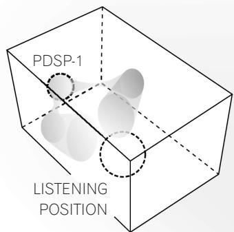
Front left-right channel
Rear left-right channel
Center channel
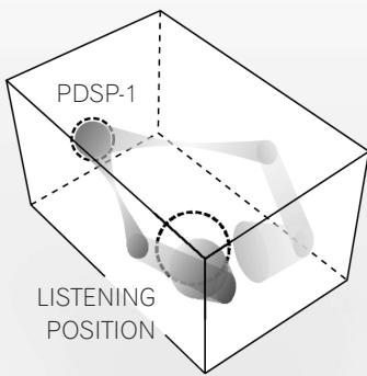
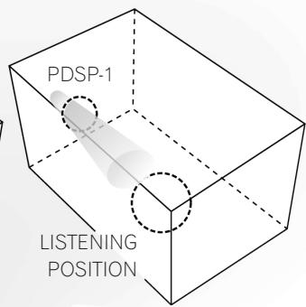
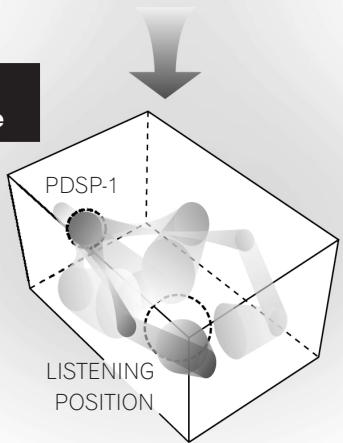
Multi-channel sound field image

2. Sound settings to match your room's characteristics
The professional installation technician uses a special metering microphone and computer to set up the unit with the optimum sound response and characteristics for your room. Since multiple sound settings are possible for any room, this unit makes it possible for you to call up preset sound environments to change the sound field in accordance with listening conditions.
3. Equipped with Dolby Digital and Pro Logic II, Digital Theater System (DTS) Decoder
In addition to Dolby Digital – the DVD video standard audio format – this unit also supports Dolby Pro Logic II, which allows you to play 2-channel sources with multi-channel ambience, and DTS, which produces high sound quality with low compression ratios and high transmission rates. These features allow you to enjoy multi-channel movie-theater ambience inside your own home.
Manufactured under license from Dolby Laboratories. "Dolby", "Pro Logic", and the double-D symbol are trademarks of Dolby Laboratories.
"DTS" and "DTS Digital Surround" are registered trademarks of Digital Theater Systems, Inc.
Manufactured under license from 1 Ltd. World-wide patents applied for. The " ① " logo and "Digital Sound Projector" are trademarks of 1 Ltd.
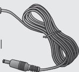
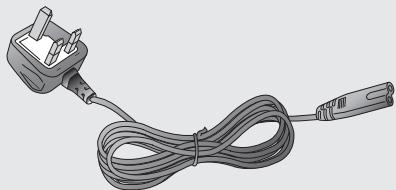
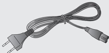
Confirm All Accessories
The digital sound projector is provided with the following accessories:

Remote control unit
Power cord
(for main unit)
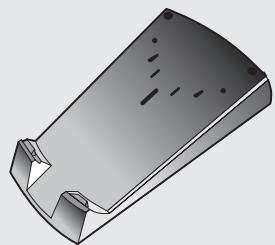
Recharger
AC adapter cord (x2)
(furnished with European model only)

AC adapter
(for remote control unit recharger)
For U.S. model

For European model


For European model (x2)


Front grille
These operating instructions
Note:
When disposing of used batteries, please comply with governmental regulations or environmental public instruction's rules that apply in your country or area.
H048 En
Caution:
Danger of explosion if battery is incorrectly replaced.
Replaced only with the same or equivalent type recommended by the manufacturer.
Discard used batteries according to the manufacturer's instructions.
H027A En
Specifications
| Audio Section | Rated output (RMS, 80 Hz - 20 kHz) | 2 W x 254 units |
| Maximum output (80 Hz - 20 kHz, 1 m) | 115 dBspl | |
| Tone control: BASS (40 Hz - 320 Hz) | ± 12 dB | |
| TREBLE (6.3 kHz - 16 kHz) | ± 12 dB | |
| Sub-woofer crossover frequency | 40 Hz - 200 Hz | |
| Output level / impedance | 1.0 Vp-p / 100 Ω | |
| Input sensitivity / impedance | 150 mVp-p / 47 kΩ | |
| Speaker response | 80 Hz - 20 kHz, ± 3dB | |
| Video Section | Video connectors (level / impedance) | 1.0 Vp-p / 75 Ω |
| S/N ratio | 55 dB | |
| Frequency response (output connectors) | 5 Hz - 10 MHz, -3 dB | |
| Power Section | Power source | AC 120 V, 60 Hz (U.S. model) AC 100 - 240 V, 50/60 Hz (European model) |
| Power consumption | 750 W | |
| Power consumption in standby mode | 3 W | |
| External Dimensions | 963 (W) x 640 (H) x 146 (D) mm (37-15/16 (W) x 25-4/16 (H) x 5-12/16 (D) in.) | |
| Weight of Main Unit | 50 kg (110 lb 4 oz) (including front grille) | |
| Accessories | Remote control unit | |
| Recharger | ||
| AC Adapter (AC 120 V, 50/60 Hz, rated voltage 6 V) (U.S. model) (AC 100 - 240 V, 50/60 Hz, rated voltage 6 V) (European model) | ||
| AC adapter cord (furnished with European model only) | ||
| Power cord | ||
| Front grille | ||
| Operating Instructions | ||
Note:
Specifications and the design are subject to possible modifications without notice, due to improvements.
Front Panel
Indicators for power and volume level, and the remote control unit sensor are located on the lower part of the panel.
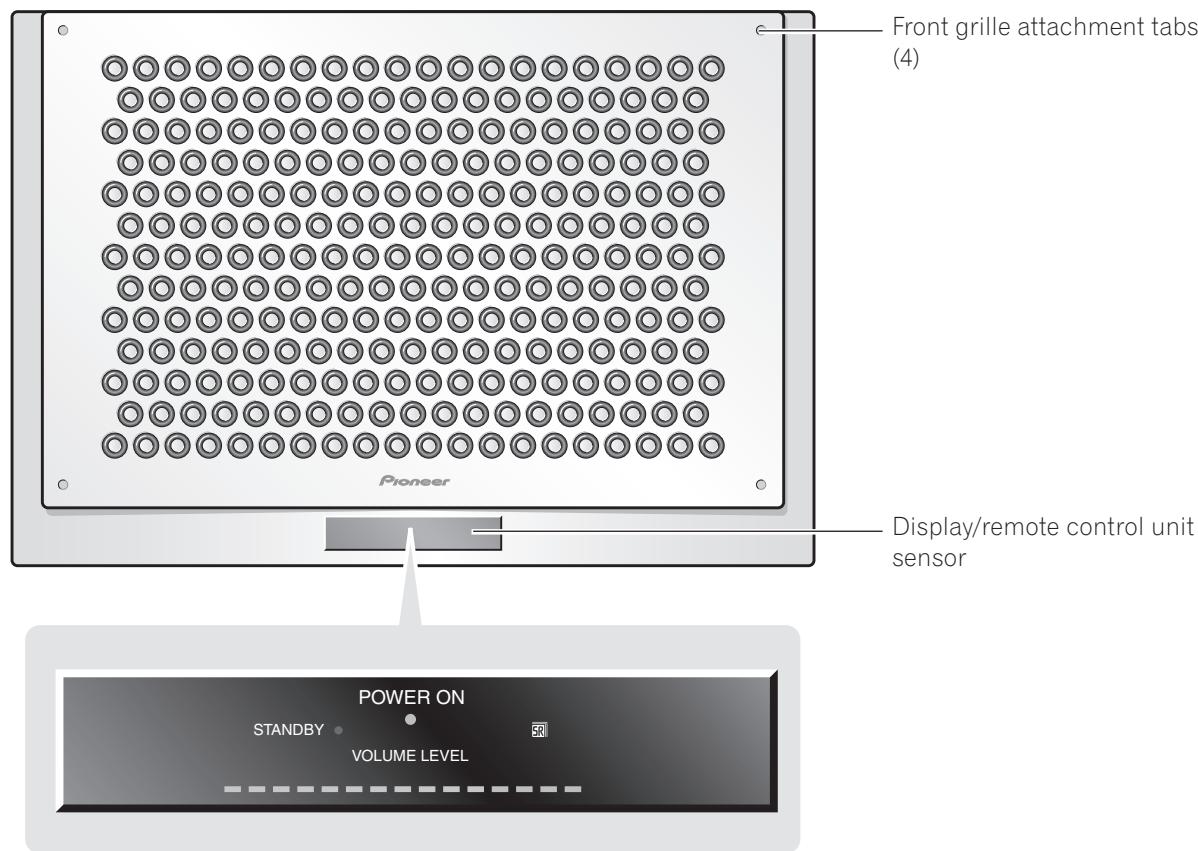
Display
Meaning/Operation
POWER ON (Blue)
Lights when power is turned ON
STANDBY (Red)
Lights in power standby mode
VOLUME LEVEL
Indicates sound volume
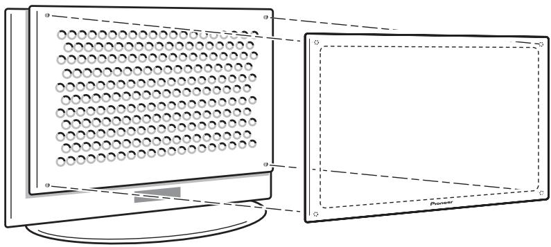
Attaching the Front Grille
Align the grille with the four attachment tabs on the front panel, then push into place.
Range of the Remote Control Unit
Operate the remote control unit while pointing it toward the Digital Sound Projector's remote control sensor within the range shown.
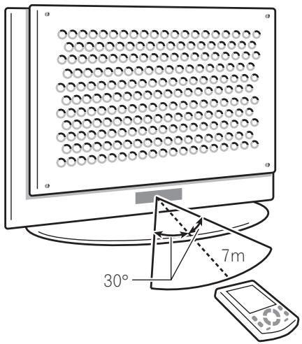
Caution:
Do not expose the remote control sensor to direct sunlight or other strong light sources.
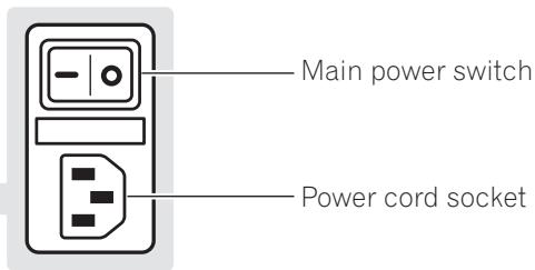
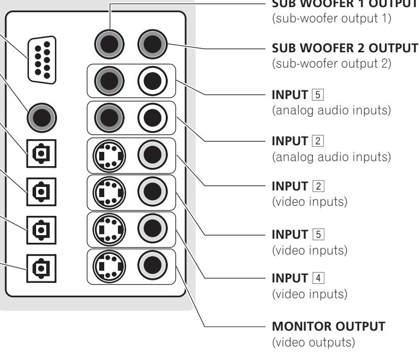
Rear Panel
The main power switch, power cord socket, and input/output connectors are located on the rear panel.
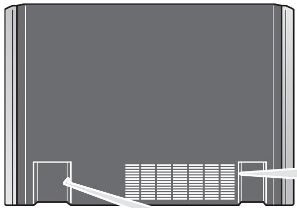
RS-232C connector (used by installation technician)
INPUT COAXIAL
(digital audio input)
INPUT 2 OPTICAL
(digital audio input)
INPUT 3 OPTICAL
(digital audio input)
INPUT 4 OPTICAL
(digital audio input)
OUTPUT OPTICAL
(digital audio output)
Turning the Main Power ON/OFF
1 Connect the supplied power cord to the rear panel power cord socket, and then insert the plug in a household power outlet.
2 Turn the main power ON/OFF by setting the main power switch to the [-] (ON) or [0] (OFF) sides.
Caution:
Do not use any power cord other than the one supplied.
About the Input/Output Connectors
Caution:
Before making or changing the connections, switch off the power and disconnect the power cord from the AC outlet.
Audio output (OUTPUT OPTICAL connector)
Use to connect MD recorders, CD recorders and other digital recording components. These connectors output the digital signals from inputs 1 to 4.
Video outputs (MONITOR OUTPUT connectors)
Use to connect a television monitor or other video component.
Note:
The selection of S or composite connectors should match the selection on the signal input side. (If an S2 video input is used, use the S output connector; if the input is composite, use the composite output connector as well).
SUB WOOFER OUTPUT connectors
Up to two sub-wooers can be connected.
Note:
Sub-woofers reproduce very low-frequency sound; coupled with the LFE (Low-Frequency Effect) channels encoded in Dolby digital and DTS audio sources, these speakers produce sounds effects which heighten the impact and realism of motion picture sound tracks and other sources.
INPUT 1-5 connectors
The digital sound projector is equipped with 5 input connector systems which can be combined in the ways shown below. The various inputs can be selected by using the INPUT1 to INPUT5 or INPUT buttons on the remote control unit.
INPUT Audio Connector Video Connector
Coaxial digital (no video)
2 Optical digital/analog S/Composite
3 Optical digital (no video)
4 Optical digital S/Composite
5 Analog S/Composite
Note:
Input provides for automatic sensing of digital and analog sources. In the event that both digital and analog signals are simultaneously input to the digital sound projector, the digital signal is given priority.
Remote Control Unit
The touch panel appears when the LCD touch panel is touched or a remote control unit button (hard key) is pressed.
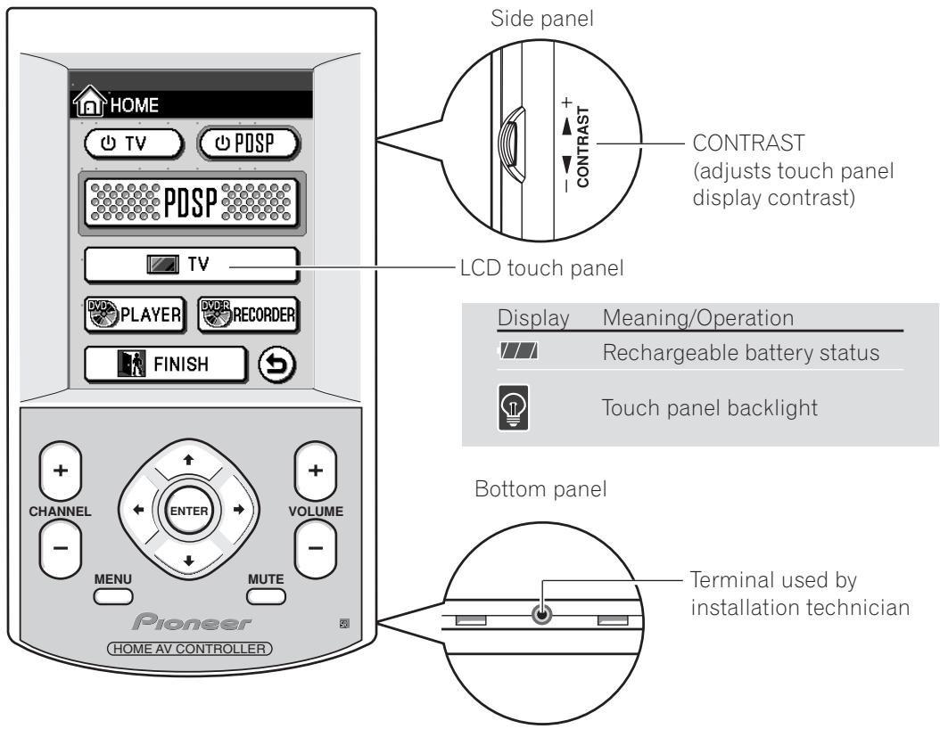
About the Remote Control Unit Buttons (hard keys)
Button
Meaning/Operation
CHANNEL
Use to select channels
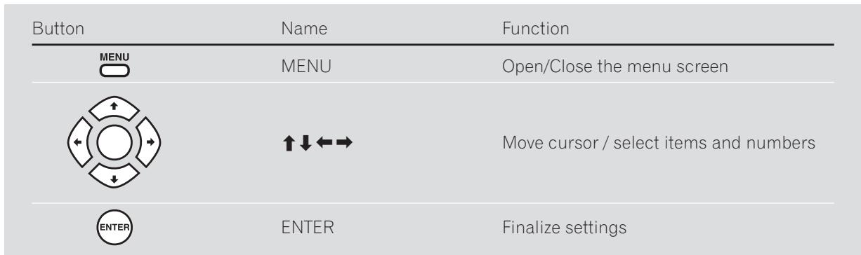
MENU
Use to turn the menu display ON/OFF
ENTER
Use to select and input menu display operations
VOLUME
Use to adjust sound volume level
MUTE
Use to temporarily turn off sound
Note:

The remote control unit buttons (hard keys) differ in function depending on which component has been selected on the touch panel. For details, see the section "Table of Remote Control Unit Menu Displays" (P40).

"Using the Remote Control Unit" "Component Operation Menu Display" P17

"Touch panel menus don't change" "Resetting the Remote Control Unit" P39
Setting the Basic Information on the Remote Control Unit
Seven items, including current time display and beep volume can be set on the remote control unit.
1 Set the touch panel to the HOME menu.
If the touch panel shows any display other than the HOME menu, press the mark at the bottom.
Press the "mark at the top left.
The setting menu will be displayed.
Use the arrows on the touch panel to switch between the two menu screens.
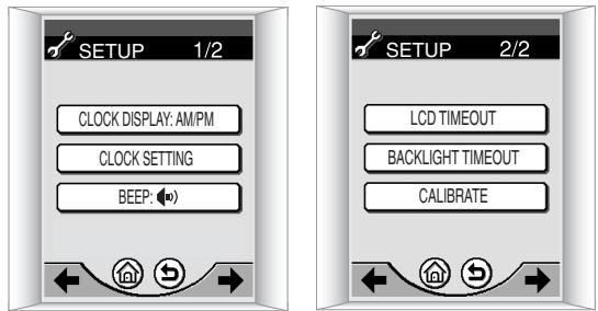
3 Follow the instructions on the screen to change the items you want.
| Item | Select | Setting Contents |
| CLOCK DISPLAY | 12-hour or 24-hour display | Type of clock display |
| CLOCK SETTING | Year/Month/Day/Hour/Minute | Date and Time |
| BEEP | / / OFF | Sound volume of beep when touch panel is pressed |
| LCD TIMEOUT | 20-120 seconds | Touch panel OFF time (if no remote control unit operation is performed during the set time, the display will automatically turn off to conserve power). |
| BACKLIGHT TIMEOUT | 20-120 seconds | How long the display illumination remains on when is pressed. |
| CALIBRATE | Fine adjustment of display screen position |
4 Once the settings are completed, press or .
The screen returns to the HOME menu.
Recharging the Remote Control Unit
1 Connect the accessory AC adapter to the recharger and a household AC outlet.
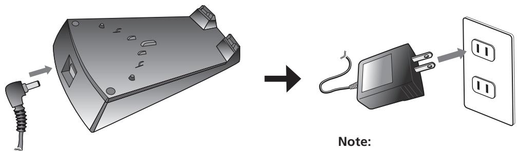

Illustration depicts U.S. model.
2 Place the remote control unit on the recharger, aligning the indents on the remote control unit with the tabs on the recharger.
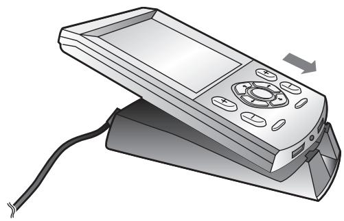
Note:
During recharging, the indicator shown below will appear on the upper right corner of the display.
Recharging indicator

Caution:
Do not use AC adapters other than the one supplied.

"Can't recharge remote control unit" P39
Using the Remote Control Unit
The remote control unit's buttons and touch panel can be used to control components connected to the digital sound projector.
Component Operation Menu Display
When using the remote control unit to control the digital sound projector and video components, menu displays are provided for the current component being used. The remote control unit has the following component menu displays:
Operation Menu
Meaning/Contents

HOME
HOME menu

PDSP
Operate Digital Sound Projector

TV
Operate television monitor

DVD PLAYER
Operate DVD player

DVD REORDER
Playback/edit on Pioneer DVD recorder

DVD REORDER
Record on Pioneer DVD recorder
Note:
The currently selected menu screen can be confirmed by looking in the upper left corner of the touch panel.

HOME
Current menu screen indicator

"About the Remote Control Unit Buttons (hard keys)" P14

"Table of Remote Control Unit Menu Displays"
P40
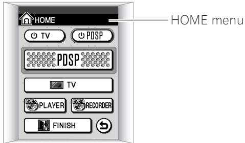
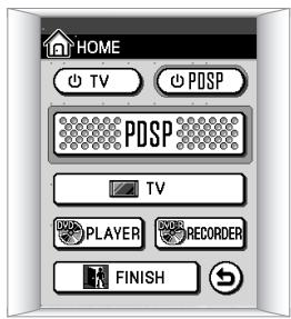
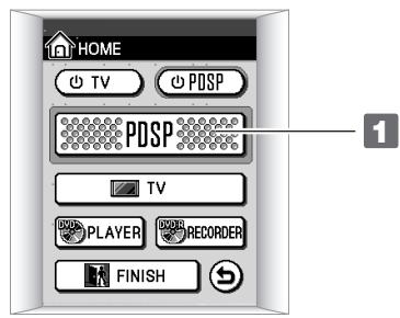
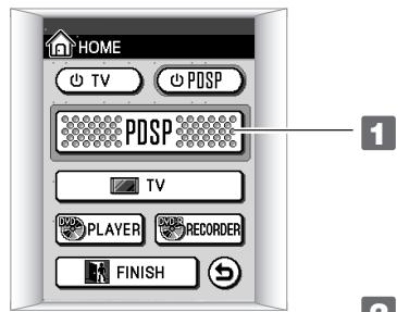
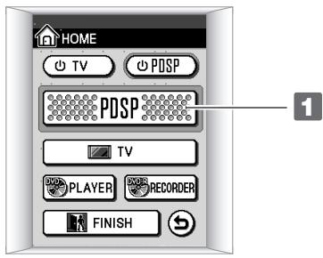
About the HOME Menu
This is the basic touch panel menu. From this menu screen, the operating menus for various connected components can be selected.
Display
Meaning/Operation
TV
Turns television power ON/OFF
POSP
Turns digital sound projector power ON/OFF

Selects the digital sound projector operating menu (→ P19)

Selects the TV operating menu (→ P21)
PLAYER
Selects the DVD player operating menu (→ P22)
RECORDER
Selects the DVD recorder operating menu (→ P24)

Turns off power to all connected components

Returns to previous menu

"Setting the Basic Information on the Remote
Control Unit" P15
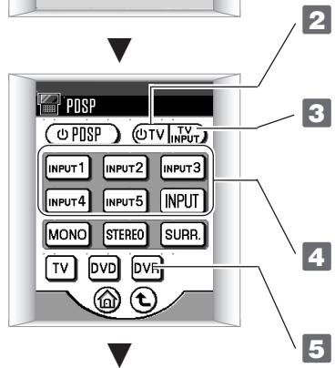
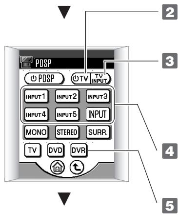
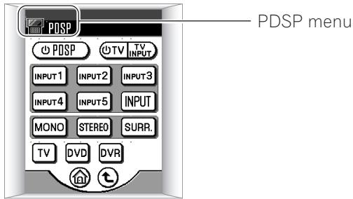
About the PDSP (digital sound projector) menu
When using the digital sound projector with other components, this menu screen is used to select operation of other components. This menu is also used to select signal inputs (input 1 to 5).
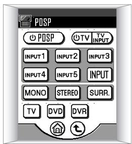
Display
Meaning/Operation
PDSP
Turns digital sound projector power ON/OFF
TV
Turns television power ON/OFF
INPUT1
Selects input 1 to 5
INPUT
Alternates between inputs 1 to 5
TV
Selects the TV operating menu (→ P21)
DVD
Selects the DVD player operating menu (→ P22)
DVR
Selects the DVD recorder operating menu (→ P24)
T
Returns to previous menu
Returns to HOME menu

"INPUT 1 - 5 connectors" P13
Operating Menus for Other Components
Use the operating menus for connected components (DVD player, television, etc.) according to the typical functions and operations of the respective component. Other operating menu items appear as follows:
Example:
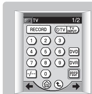
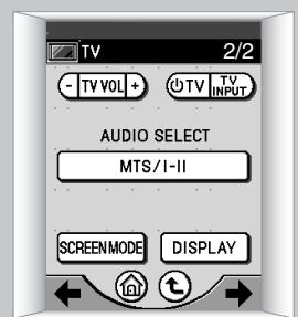
Television Operating Menu
Display
Meaning/Operation

Selects the PDSP menu (→ P19)

Selects the recording menu for DVD recorder (→ P23)

Returns to HOME menu

Returns to previous menu

Changes between the menu screens (1/2, 2/2)
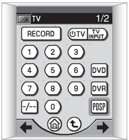
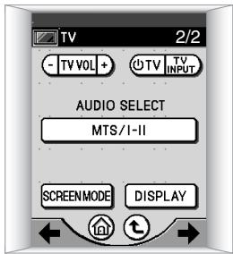
Watching Television
Use this menu to operate a connected television.
Turn on power to digital sound projector.


Turn on power to television.
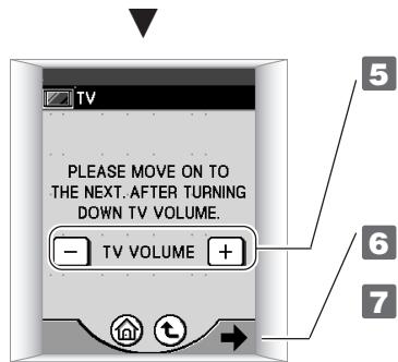

Select input connected to television sound.


Change to television operating menu.
1/2
2/2
Note:
When TV is pressed in step 1, the television operating screen shown in 7 appears, and the television can be operated without using the digital sound projector. Note that in this case, the -TV vol + item does not appear on the 2/2 menu, with the result that the remote control unit's volume button (hard key) must be used to adjust the television sound volume.

"About the Remote Control Unit Buttons (hard keys)" P14

"Table of Remote Control Unit Menu Displays"
→ P40
Watching a DVD
Use this menu to operate a connected DVD player.

Turn on the power to the digital sound projector.

Turn on the power to the television monitor.

Set television input to digital sound projector.

Select the input connected to the DVD player.

Change to DVD player operating menu.
The accompanying three menus are used to operate the DVD player.
Use the arrows on the touch panel to change between the menu screens.
DVD Player Operating Menus (3 screens)
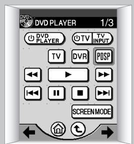
1/3
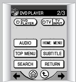
2/3
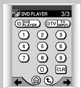
3/3
Notes:
If a Pioneer DVD player is connected, the DVD player's power will turn on in step 5.
If PLAYER is pressed in step 1, the DVD player operating menus shown in step 6 will appear, and it will be possible to operate the DVD player without using the digital sound projector.

"INPUT 1-5 connectors" P13
Using a Pioneer DVD Recorder
Use this menu to operate a connected Pioneer DVD Recorder.
Recording
To record the program currently playing on the television, follow the steps listed below.
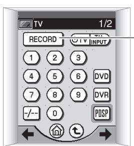
Steps 1 - 6 are the same as steps 1 - 6 on P21 "Watching Television".

RECORD
Change to recording menu on DVD recorder.
DVD Recorder: Recording Menu (2 screens)
1/2

2/2

Perform recording operations on menu 1/2 at left.
HDD/DVD: Selects type of disk for recording (HDD/DVD)
DISPLAY: Displays disc information
REC MODE: Selects recording mode FINE/SP/LP/EP
AUDIO: Selects audio channel for recording (main/sub)
REC: Starts recording
STOP REC: Stops recording
Note:
Press on the first screen to change to menu screen 2/2; this menu allows playback and confirmation of recorded contents.

"Watching Television" P21
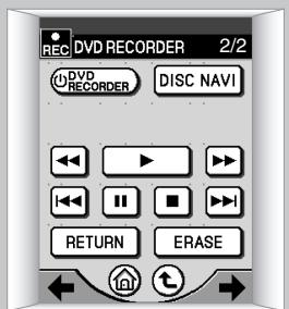
Playback/Editing

Change to digital sound projector menu.

Turn on TV power.

Set television video input to digital surround projector.

Select input connected to DVD recorder.

Change to DVD recorder operation menu.

The following four menus are used to operate the DVD recorder.
Use the arrows on the touch panel to change between the menu screens.
DVD Recorder Operating Menus (4 screens)
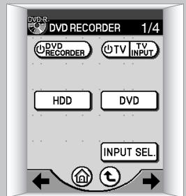
1/4
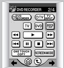
2/4
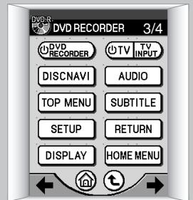
3/4
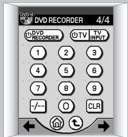
4/4
Note:
When REcORDER is pressed in step 1, the DVD recorder operating menu shown in 6 appears, and the DVD recorder can be operated without using the digital sound projector.
Caution:
Some operations may not be possible, depending on the specific model of Pioneer DVD Recorder connected.
Selecting the Audio Mode
Listening to Stereo Sound in Surround Mode
Stereo broadcasts, CD playback and other 2-channel sounds can be enjoyed in surround sound mode.
1 Set the touch panel to the PDSP menu.
From the HOME menu, press Posp; from other menus, press Posp.
2 Press SURR.
The television screen will display the audio mode. Each time the button is pressed, the audio mode will change in the following order.
PLII Movie
PLII Movie: Pro Logic II Movie
This mode is designed for use with film soundtracks, and allows actors' dialogue to be heard from the most natural direction.
PLII Music
PLII Music: Pro Logic II Music
This mode is designed for use with music sources. The surround effect recreates the ambience experienced in live performances.
Pro Logic
Pro Logic:
The Pro Logic Mode is generally designed for general use with movie soundtracks. The rear channel track is heard in monaural surround.
Stereo
Stereo:
The stereo mode is a two-channel mode; when this mode is selected, even multi-channel sources are played back in two channels, and heard from the front right and left.
Notes:
If SRR is pressed during playback of Dolby Digital and other surround sources, the following message will be displayed:
Dolby Digital
IfSTEREO is pressed in step 2, the unit will change to stereo mode.

"Fine Tuning the PLII Music Mode" P35
Enhancing Monaural Sources
When listening to older movies and CDs, and other sources recorded in monaural sound, the sound will seem more natural when heard from the center channel alone, rather from the front two channels (right and left).
1 Set the touch panel to the PDSP menu.
From the HOME menu, press PDSP; from other operation menus, press PDSP.
Press MONO
The "Mono" indicator will appear on the television screen.
Each time the button is pressed, the monaural mode alternates between ON and OFF.
Mono
Caution:
When adjusting the digital sound projector's sound, the menu screen is displayed on the connected television monitor. To see the display, turn on the television's power and set the television's video input to the digital sound projector.
Note:
When adjusting the digital sound projector's sound, use the following buttons (hard keys) of the remote control unit:
Changing Surround Sound
You can adjust each channel's volume/balance while listening to the actual sound, as well as adjusting the subwoofer and other options.
Test Signal
A test signal can be used to adjust the output level of each channel.
1 Use the touch panel to select the PDSP menu.
From the HOME menu, press PDSP; from other menus, press Posp.
Press the MENU button.
The following "System Setup" menu appears.
System Setup
1 Surround Setup
2 All Ch Tone Control
3 Recall Memory
4 Lipsync delay
5 Stereo Mode


"Digital sound projector menu screens don't appear" P38

"Changing Each Channel's Output Level" P29
Using the buttons, select "Surround Setup", and press the ENTER button.
The following screen appears:
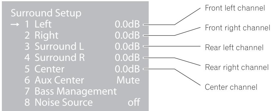
Note:
"Aux Center" is an additional center channel. To use the "Aux Center" channel, a special dedicated setting is required; consult your installation service personnel.
4 Using the buttons, select "Noise Source", and press the ENTER button.
The following screen appears:
Noise Source 1 Off
2 Left
3 Right
4 Surround L
5 Surround R
6 Center
7 Aux Center
8 LFE
Using the buttons, select the channel, and press the ENTER button.
The test signal will be produced from the selected channel.

"Sub Woofer / Bass Management" P30
Changing Each Channel's Output Level
1 - 3 (Same as steps 1 - 3 on P27, "Test Signal")
The following screen appears:
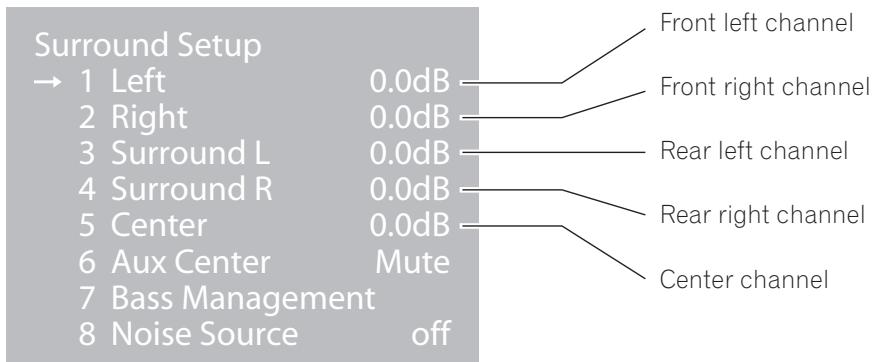
4 Using the buttons, select the desired channel, then press the ENTER button.
The following screen appears:

Using the buttons, adjust the output level as desired, then press the ENTER button.
Adjust the output level while listening to the test signal.
Setting range: 0.0dB - 12.0dB
Note:
When you're finished, you can press the MENU button repeatedly to return to previous screens.
Sub Woofer / Bass Management
This menu allows you to set the unit for a sub-woofer, and LFE channel ON/OFF.
1 - 3 (Same as steps 1 - 3 on P27, "Test Signal")
4 Using the buttons, select "Bass Management", and press the ENTER button. The following screen appears:
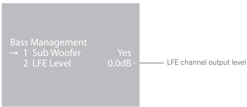
Notes:
LFE means "Low Frequency Effect".
If "Sub Woofer" is set to "Yes", use the buttons to select "LFE level", then use the buttons to adjust the output level.
Setting range: 0.0dB - 12.0dB
Using the buttons, select "Sub Woofer", then press the ENTER button. The following screen appears:
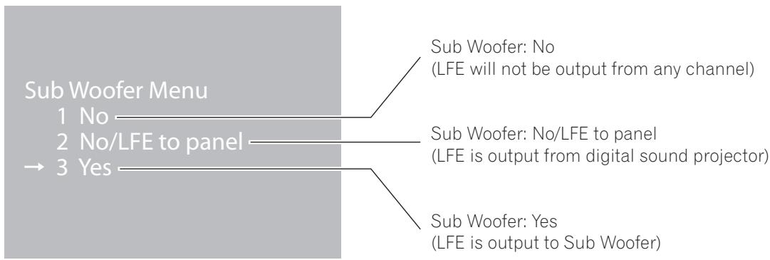
Using the buttons, select either "No," "No/LFE to panel," or "Yes," then press the ENTER button.
Note:
When you're finished, you can press the MENU button repeatedly to return to previous screens.

"SUB WOOFER OUTPUT connectors" P13
Adjusting the Tone
You can adjust the overall tone for all audio channels.
1 Use the touch panel to select the PDSP menu.
From the HOME menu press PDSP; from other menus, press PDSP
Press the MENU button.
The "System Setup" menu screen appears.
3 Using the buttons, select "All Ch Tone Control", and press the ENTER button.
The following screen appears:
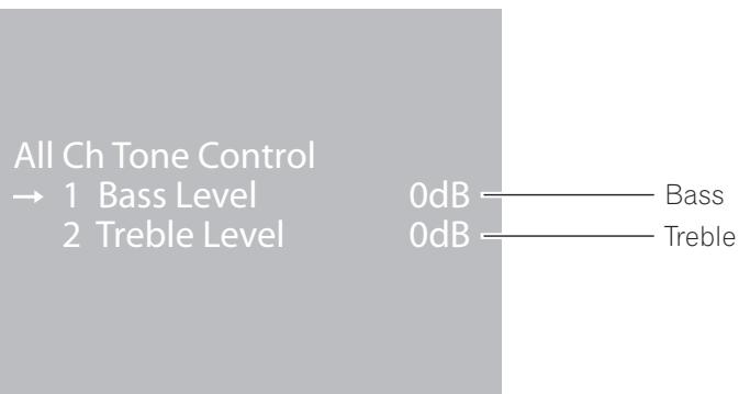
4 Using the buttons, select either "Bass Level" or "Treble Level", then press the ENTER button.
The following screen appears:
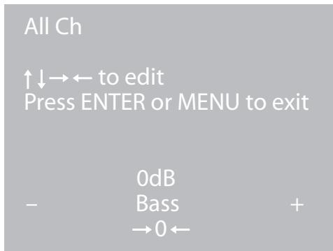
Using the buttons, adjust the tone level as desired, then press the ENTER button.
Setting range: -12dB + + 12dB
Note:
When you're finished, you can press the MENU button repeatedly to return to previous screens.
Calling Up a Room Sound Setting
Multiple sound settings can be recorded in accordance with measured room characteristics. Select the setting that produces the optimum listening environment.
1 Use the touch panel to select the PDSP menu.
From the HOME menu press PDSP; from other menus, press Posp.
Press the MENU button.
The "System Setup" menu displays a menu of the following three types of settings:
Using the buttons, select "Recall Memory", then press the ENTER button.
The following screen appears.
Recall from..
1 Memory 1
2 Memory 2
3 Memory 3
4 Memory 4
5 Memory 5
6 Memory 6
7 Memory 7
8 Memory 8
Using the buttons, select the desired sound setting, then press the ENTER button.
Notes:
When you're finished, you can press the MENU button repeatedly to return to previous screens.
A maximum of eight room sound settings can be stored in memory. Consult your installation service personnel regarding the settings that will work best with your room.
Video and Audio Timing Compensations (Lipsync delay)
The video playback from some components may appear somewhat delayed from the audio channel. If actors' mouth movements appear to be out of sync with the audible soundtrack, use this adjustment to delay (compensate) the audio timing.
1 Use the touch panel to select the PDSP menu.
From the HOME menu press PDSP; from other menus, press Psp.
Press the MENU button.
The "System Setup" menu appears.
3 Using the buttons, select "Lipsync delay", then press the ENTER button.
The following screen appears:
Lipsync delay
to edit
Press ENTER or MENU to exit
Delay 0ms
4 Using the buttons, adjust the amount of delay as desired, then press the ENTER button.
Perform this adjustment while confirming the actual video-audio timing.
Notes:
The maximum adjustment value will be less than 106 ms, as a result of the initial room setting made by the service personnel.
When you're finished, you can press the MENU button repeatedly to return to previous screens.
Adjusting Surround Effects
Narrowing the audio width of the front right-left channels (Image width)
As a characteristic of the digital sound projector, when the room's right and left walls are far apart, some playback sources may sound overly separated.
This function allows you to adjust the width of the sound image to a narrow perspective, thus producing a more natural sound image.
1 Use the touch panel to select the PDSP menu.
From the HOME menu press PDSP; from other menus, press Posp.
Press the MENU button.
The "System Setup" menu screen appears.
Using the buttons, select "Stereo Mode", then press the ENTER button.
The following screen appears:
Stereo Mode Menu
1 Image width On
2 Image width value 1.00
3 PLII Mode PLII Movie
Using the buttons, select "Image width", then use the buttons to select "On".
Using the buttons, select "Image width value", then use the buttons to adjust the value as desired; when done, press the ENTER button.
Setting range: 0.00 - 1.00 (1.00 when setting is OFF)
Notes:
Setting value 1.00 is for stereo sound (sound width spread to front right-left).
Setting value 0.00 is monaural (sound spread is narrowed and produced only from the center channel).
When you're finished, you can press the MENU button repeatedly to return to previous screens.

"Fine Tuning the PLII Music Mode" P35
Fine Tuning the PLII Music Mode
When listening to a two-channel source in surround sound using the PLII Music mode, you can fine tune the effect from the "Stereo Mode Menu".
1 Use the touch panel to select the PDSP menu.
From the HOME menu press PDSP; from other menus, press PDSP
Press the MENU button.
The "System Setup" menu screen appears.
3 Using the buttons, select "Stereo Mode", then press the ENTER button.
The following screen appears:
Stereo Mode Menu
1 Image width On
2 Image width value 1.00
3 PLII Mode PLII Movie
4 Using the buttons, select "PLII Mode", then press the ENTER button.
The following screen appears:
PLII Mode
1 PLII Off
→ 2 Movie
3 Music
4 Pro Logic


"Selecting the Audio Mode"
(Dolby Pro Logic II) P25
Using the buttons, select "Music", then press the ENTER button.
Using the buttons, select "Panorama", "Center width", or "Dimension", then use the buttons to set the effect as desired.
Stereo Mode Menu
1 Image width On
2 Image width value 1.00
→3 PLII Mode PLII Music
4 Panorama Off
5 Center width 0
6 Dimension 3
| Display | Setting | Effect |
| Panorama | On/Off | The front sound image expands toward the rear as well, enveloping the listener in surround sound. |
| Center width | 0-7 | Adjusts the audible width of the center channel (0 means sound is produced from the center channel; as the numerical value rises, the sound width expands, until at 7 the sound is produced from the front right-left channels). |
| Dimension | 0-6 | Shifts the surround effect balance between front and back (0 means sound is toward the front; as the numerical value increases, the balance shifts toward the back, until at 6 it is produced from the rear channel). |
Note:
When you're finished, you can press the MENU button repeatedly to return to previous screens.
Displaying the Data Screen
Use this function to confirm information about the currently playing audio and video source, and room sound settings.
1 Use the touch panel to select the PDSP menu.
From the HOME menu press PDSP; from other menus, press POSP
Press the ENTER button.
The "Status" menu screen appears as shown below.
Status
Source Input 2D
Memory 1
Mode PLII Movie
Width 1.00
| Item | Contents | Display Example |
| Source | Input/Signal type | Input 1-5, 2D (digital), 2A (analog) |
| Memory | Preset sound setting | 1-8, * (when a change has occurred to the called-up sound setting) |
| Mode | Audio mode type | PLII Movie, PLII Music, Pro Logic, Stereo, Mono |
| Width | Image width setting | 0.00-1.00 (image width setting value), Off |
3 After confirming the data, press the ENTER button.
The "Status" menu screen disappears.

"INPUT 1 - 5 connectors" P13

"Calling Up a Room Sound Setting" (Memory 1-8) P32

"Selecting the Audio Mode" (Dolby Pro Logic II) P25

"Adjusting Surround Effects" (Image width) P34
Troubleshooting
Many malfunctions can be the result of operating errors. If you experience trouble with the digital sound projector, use this troubleshooting guide together with thorough checks of the other components in your system. If the problem is not corrected after doing so, consult your authorized service center.
Sound Problems?
No sound
- Use the remote control unit's PDSP menu to check INPUTs 1-5, and confirm you have selected the correct input. P19
- Check the front panel VOLUME LEVEL indicator to confirm whether the MUTE button has been pressed, or if the sound volume has been set to its minimum setting. P10
- Confirm that the digital sound projector's main power is turned ON and that the front panel's POWER ON indicator (Blue) is lighted. P10
Sound has a poor surround effect
- Confirm whether the audio mode has been set to "Mono" for monaural sound. P26
- Confirm whether the audio mode has been set to "Stereo" for stereo sound. P25
- Check the playback source to confirm that it is a multi-channel source.
Sound has poor balance
- Confirm that the proper room sound setting has been chosen. P32
- If the digital sound projector has been physically moved, or if the furniture in the room been significantly rearranged or changed, consult your installation technician to have the digital sound projector recalibrated for the new room environment.
No sound from the connected sub-woofer, or sound volume is too low
- Confirm whether the sub-woofer's output level has been set low. P30
Recording isn't possible on the connected components
- If the playback source is a digital signal, it may be protected with a copyguard function, in which case it cannot be recorded. In this case, use an analog connection between the playback component and recording component, and record the source in analog mode.
Video Problems?
Digital sound projector menu screens don't appear
- Confirm that the proper video input has been selected on the television monitor.
No image is visible on the connected TV monitor.
- Confirm that the proper video input has been selected on the television monitor.

Problems with Use or Operation?
Can't recharge remote control unit
- Check the recharge indicator in the upper right corner of the remote control unit's touch panel to confirm whether the remote control unit is sitting on the recharger and recharging correctly.
- If the remote control unit's battery won't hold a sufficient charge to allow use of the remote control unit even after proper recharging, the unit's Lithium-ion battery may require replacing. In this event, consult your authorized Pioneer service center. The remote control unit's Lithium-ion battery cannot be purchased at any location other than an authorized Pioneer service center.
Remote control unit doesn't work
- Check that the main power switch is turned on, the power cord is connected securely, and the front panel's POWER ON (Blue) or STANDBY (Red) indicator is lighted. P10
- Check the remote control unit's remaining charge indicator to confirm that the remote control unit's battery is properly recharged. P14
- You may be using the remote control too far from the sensor (Try moving closer to the digital sound projector). P11
- Remote operation may become unreliable if direct sunlight, a fluorescent lamp, or other strong light source is striking the remote control sensor on the front panel.
Remote control unit doesn’t operate connected Pioneer DVD recorder
- Depending on the model, some functions may not be supported.
Touch panel menus don't change
- If the remote control menu screens do not change, try using the following procedure to reset the remote control unit. Resetting the remote control unit will not erase recorded settings.
If the unit does not operate normally due to external effects (such as static electricity)
- Disconnect the power plug from the outlet and insert again to return to normal operating conditions.
Resetting the Remote Control Unit
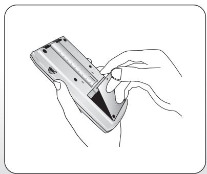
1 Use a Phillips screwdriver to remove the screw on the back panel of the remote control unit.

2 Remove the panel.
Use a narrow pointed object to press the RESET button.
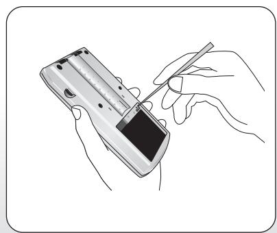
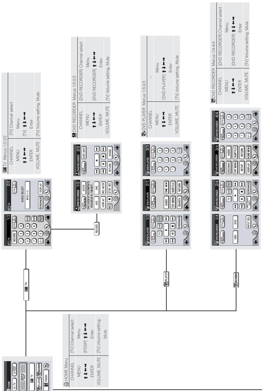
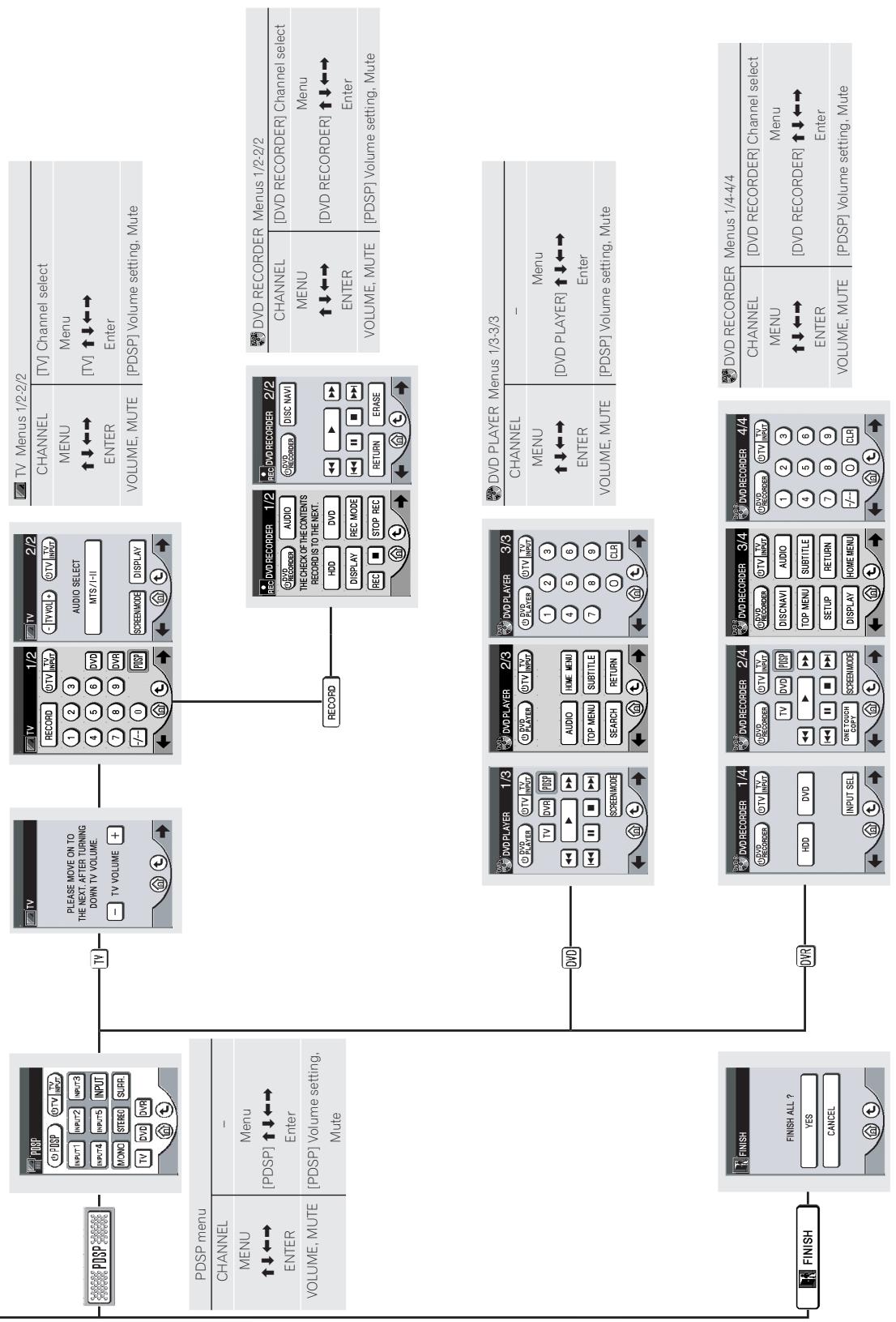
Table of Remote Control Unit Menu Displays
Table of Remote Control Unit Menu Displays
The following table shows all operating menu displays on the remote control unit's touch panel display. Depending on the way you navigate through the operating menus, the component corresponding to the remote control unit's buttons (hard keys) will change. To confirm what component and functions are supported, consult the remote control unit's function table for each operating menu display.

eouieuee euee iippv
Index
The following index of keywords has been collected based on the four following item categories:
- Terms displayed in menus
- Terms on front panel / rear panel
- Symbols and terms on remote control unit / touch panel
- Terminology in these operating instructions
Terms displayed in menus
page
All Ch Tone Control 31
Aux Center 28
Bass 31
Bass Management 30
Center width 36
Delay 33
Dimension 36
Dolby Digital 25
Image width 34
LFE 30
Lipsync delay 33
Memory 32
Mono 26
Noise Source 27
Panorama 36
Pro Logic 25
PLII Mode 35
PLII Movie 25
PLII Music 25
Recall from 32
Recall Memory 32
Status 37
Stereo 25
Stereo Mode 34, 35
Sub Woofer 30
Surround Setup 28
System Setup 27
Treble 31
Terms on front panel / rear panel
page
COAXIAL 12
INPUT 1-5 12
MONITOR OUTPUT 12
OPTICAL 12
OUTPUT OPTICAL 12
POWER ON 10
RS-232C 12
STANDBY 10
SUB WOOFER 1 OUTPUT 12
SUB WOOFER 2 OUTPUT 12
VOLUME LEVEL 10
Symbols and terms on remote control unit / touch panel
page
CHANNEL 14
CONTRAST 14
DVD PLAYER 22
DVD REORDER 23, 24
ENTER 14
FINISH 18
HOME 18
INPUT 19
MENU 14
MONO 26
MUTE 14
PDSP 19
RECORD 23
RESET 39
SETUP 15
STEREO 25
SURR. 25
TV 21
VOLUME 14
14
14
E D- 16
(5) 18
20
(5) 19, 20
19,20
Terminology in these operating instructions
page
Beam control technology 6
Composite connector (video input) 13
Dolby Digital 7
DTS 7
FrontGrille 11
Lithium-ion battery 8, 39
Main power switch 12
Power cord 12
Pro Logic II 7,25,35
Recharger 16
Remote control signal sensor 10
Reset 39
S connector (video input) 13
AFTER-SALES SERVICE FOR PIONEER PRODUCTS
Please contact the dealer or distributor from where you purchased the product for its after-sales service (including warranty conditions) or any other information. In case the necessary information is not available, please contact the Pioneer's subsidiaries (regional service headquarters) listed below:
PLEASE DO NOT SHIP YOUR PRODUCT TO THE COMPANIES at the addresses listed below for repair without advance contact, for these companies are not repair locations.
AMERICA
PIONEER ELECTRONICS (USA) INC.
CUSTOMER SUPPORT DIVISION
P.O. BOX 1760, LONG BEACH, CA 90801-1760, U.S.A.
CUSTOMER SERVICE HOTLINE : (800) 421-1404
EUROPE
PIONEER EUROPE NV
EUROPEAN SERVICE DIVISION
HAVEN 1087, KEETBERGLAAN 1, B-9120 MELSELE, BELGIUM
ASEAN
PIONEER ELECTRONICS ASIACENTRE PTE. LTD.
SERVICE DEPARTMENT
253, ALEXANDRA ROAD #04-01 SINGAPORE 159936
JAPAN AND OTHERS
PIONEER CORPORATION (HEAD OFFICE)
CUSTOMER SUPPORT CENTER
Published by Pioneer Corporation.
Copyright © 2003 Pioneer Corporation.
All rights reserved.

- DIGITAL SOUND PROJECTOR
- PDSP-1
- IMPORTANT
- FOR USE IN THE UNITED KING
- DOM.
- NOTE
- INSTALLATION
- Note: Reference is made to ISO/IEC Guide 37 [12].
- VENTILATION:
- Operating Environment
- Operating environment temperature and humidity:
- CAUTION
- RISK OF ELECTRIC SHOCK DO NOT OPEN
- IMPORTANT SAFETY INSTRUCTIONS
- [For U.S. model]
- IMPORTANT NOTICE
- POWER-CORD CAUTION
- Information to User
- CAUTION:
- Maintenance of External Surfaces
- Regarding Installation
- Dear Customer:
- To establish a safe level:
- Once you have established a comfortable sound level:
- We Want You Listening For A Lifetime
- Decibel
- Level Example
- THE FOLLOWING NOISES CAN BE DANGEROUS UNDER CONSTANT EXPOSURE
- Contents
- Preface
- Parts and their Functions
- Using the Digital Sound Projector
- Adjusting the Sound
- Additional Information
- Regarding Installation and Initial Settings
- Features
- Beam control technology
- BEAM CONTROL TECHNOLOGY
- Audio beam image
- Sound settings to match your room's characteristics
- Equipped with Dolby Digital and Pro Logic II, Digital Theater System (DTS) Decoder
- Confirm All Accessories
- Note:
- Specifications
- Front Panel
- Attaching the Front Grille
- Range of the Remote Control Unit
- Rear Panel
- Turning the Main Power ON/OFF
- About the Input/Output Connectors
- Audio output (OUTPUT OPTICAL connector)
- Video outputs (MONITOR OUTPUT connectors)
- SUB WOOFER OUTPUT connectors
- INPUT 1-5 connectors
- Remote Control Unit
- About the Remote Control Unit Buttons (hard keys)
- Setting the Basic Information on the Remote Control Unit
- Set the touch panel to the HOME menu.
- Press the "mark at the top left.
- Follow the instructions on the screen to change the items you want.
- Once the settings are completed, press or .
- Recharging the Remote Control Unit
- Connect the accessory AC adapter to the recharger and a household AC outlet.
- Place the remote control unit on the recharger, aligning the indents on the remote control unit with the tabs on the recharger.
- Using the Remote Control Unit
- Component Operation Menu Display
- About the HOME Menu
- About the PDSP (digital sound projector) menu
- Operating Menus for Other Components
- Watching Television
- Watching a DVD
- Notes:
- Using a Pioneer DVD Recorder
- Recording
- Playback/Editing
- Selecting the Audio Mode
- Listening to Stereo Sound in Surround Mode
- Set the touch panel to the PDSP menu.
- Press SURR.
- PLII Movie: Pro Logic II Movie
- PLII Music: Pro Logic II Music
- Pro Logic:
- Stereo:
- Enhancing Monaural Sources
- Press MONO
- Changing Surround Sound
- Test Signal
- Use the touch panel to select the PDSP menu.
- Press the MENU button.
- Using the ↔ buttons, select "Surround Setup", and press the ENTER button.
- Using the ↔ buttons, select "Noise Source", and press the ENTER button.
- Using the ↔ buttons, select the channel, and press the ENTER button.
- Changing Each Channel's Output Level
- - 3 (Same as steps 1 - 3 on P27, "Test Signal")
- Using the ↔ buttons, select the desired channel, then press the ENTER button.
- Using the ↔ buttons, adjust the output level as desired, then press the ENTER button.
- Sub Woofer / Bass Management
- Using the ↔ buttons, select "Bass Management", and press the ENTER button. The following screen appears:
- Using the ↔ buttons, select "Sub Woofer", then press the ENTER button. The following screen appears:
- Using the ↔ buttons, select either "No," "No/LFE to panel," or "Yes," then press the ENTER button.
- Adjusting the Tone
- Calling Up a Room Sound Setting
- Video and Audio Timing Compensations (Lipsync delay)
- Adjusting Surround Effects
- Narrowing the audio width of the front right-left channels (Image width)
- Using the ↔ buttons, select "Stereo Mode", then press the ENTER button.
- Using the buttons, select "Image width", then use the ↔ buttons to select "On".
- Using the buttons, select "Image width value", then use the ↔ buttons to adjust the value as desired; when done, press the ENTER button.
- Fine Tuning the PLII Music Mode
- Displaying the Data Screen
- Troubleshooting
- Sound Problems?
- No sound
- Sound has a poor surround effect
- Sound has poor balance
- No sound from the connected sub-woofer, or sound volume is too low
- Recording isn't possible on the connected components
- Video Problems?
- Digital sound projector menu screens don't appear
- No image is visible on the connected TV monitor.
- Can't recharge remote control unit
- Remote control unit doesn't work
- Remote control unit doesn’t operate connected Pioneer DVD recorder
- Touch panel menus don't change
- If the unit does not operate normally due to external effects (such as static electricity)
- Resetting the Remote Control Unit
- Table of Remote Control Unit Menu Displays
- eouieuee euee iippv
- Index
- Terms displayed in menus
- page
- Terms on front panel / rear panel
- Symbols and terms on remote control unit / touch panel
- Terminology in these operating instructions
- AFTER-SALES SERVICE FOR PIONEER PRODUCTS
- AMERICA
- EUROPE
- ASEAN
- JAPAN AND OTHERS
Brand : PIONEER
Model : PDSP-1
Category : CD Player