
FD8166-F3 - Security Camera Vivotek - Free user manual and instructions
Find the device manual for free FD8166-F3 Vivotek in PDF.


| Product Type | Security Camera |
| Brand | Vivotek |
| Model | FD8166-F3 |
| Resolution | 2 MP (1920x1080) |
| Lens Focal Length | 3.6 mm (model suffix F3) |
| Field of View | Wide angle (approx. 90-100°) |
| Power Supply | PoE (Power over Ethernet) only, IEEE 802.3af |
| Connectivity | Ethernet 10/100 Base-T, RJ-45 |
| Mounting Type | Ceiling or wall mount |
| Enclosure Rating | Indoor use only |
| Dimensions (approx.) | Diameter 110 mm, height 90 mm |
| Weight (approx.) | 300 g |
| Operating Temperature | 0°C to 50°C (32°F to 122°F) |
| Package Contents | Camera, Quick Installation Guide, Warranty Card, Focus Adjustment Tool, Screws, Software CD |
| Software Included | Installation Wizard 2, 32-channel recording software |
| Installation Requirements | Cat5 or better Ethernet cable, PoE switch or injector |
| Focus Adjustment | Manual via included tool |
| Tilt Adjustment | Via Phillips screwdriver |
| Pan Adjustment | Manual rotation 360° |
| Safety Warnings | Do not touch during lightning, avoid moisture, power off if smoke or odor |
| Cleaning Instructions | Use clean cotton cloth for dome cover, avoid sharp objects |
| Spare Parts / Repairability | Contact distributor; no user-serviceable parts inside |
| Certifications | PoE compliant, CE, FCC |
Frequently Asked Questions - FD8166-F3 Vivotek
User questions about FD8166-F3 Vivotek
0 question about this device. Answer the ones you know or ask your own.
Ask a new question about this device
Download the instructions for your Security Camera in PDF format for free! Find your manual FD8166-F3 - Vivotek and take your electronic device back in hand. On this page are published all the documents necessary for the use of your device. FD8166-F3 by Vivotek.
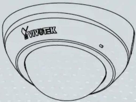
USER MANUAL FD8166-F3 Vivotek
2MP • Stylish Design • Easy Installation

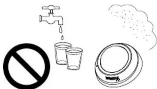
Warning Before Installation
Power off the Network Camera as soon as smoke or unusual odors are detected.

Contact your distributor in the event of occurrence.
Do not place the Network Camera on unsteady surfaces.
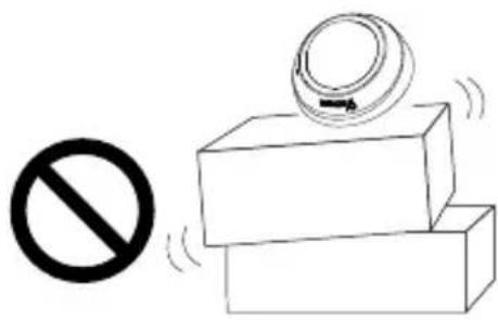
natural_image
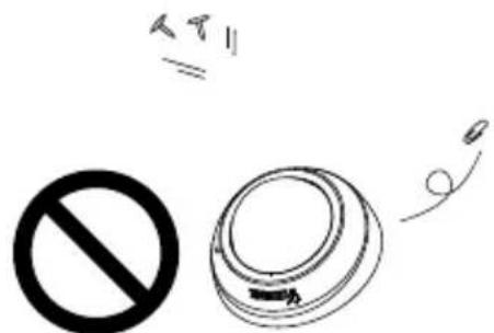
Simple line drawing of a prohibition symbol and stacked blocks with motion lines (no text or labels)Do not insert sharp or tiny objects into the Network Camera.
Keep the Network Camera away from water. If the Network Camera becomes wet, power off immediately.

Contact your distributor in the event of occurrence.
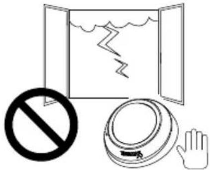
Do not touch the Network Camera during a lightning storm.
Do not place the Network Camera in high humidity environments.
1 Package Contents

FD8166
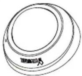
natural_image
Simple line drawing of a circular object with a label, no text or symbols present
Quick Installation Guide / Warranty Card
natural_image
Close-up of a circular ring object with no visible text or symbols

Focus Adjustment Tool
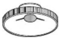

Screws
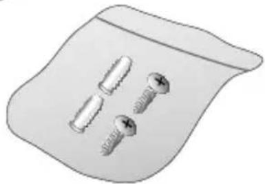
natural_image
Illustration of two screws on a surface with a magnified view of them (no text or symbols)
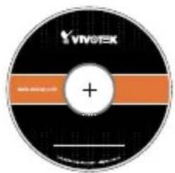
Software CD

NOTE:
All cables are user-supplied. Use a CAT5 standard UTP or better quality cable. In order to pass the Ethernet cable through the routing path, the maximum cable diameter allowed is 5.2mm.
EN - 2
2 Physical Description
Outer View
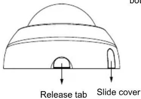
Leave the slide cover in place if you route cables through the bottom and then through a hole on the ceiling or wall.
Inner View
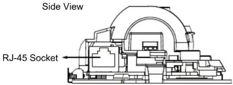
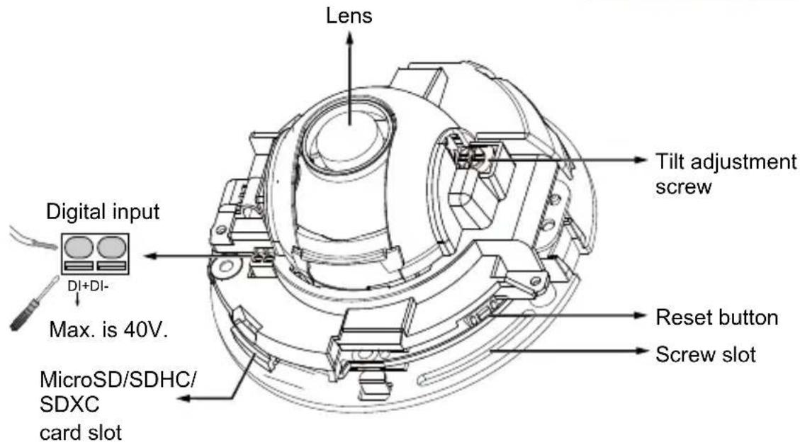
EN - 3
3
Hardware Installation

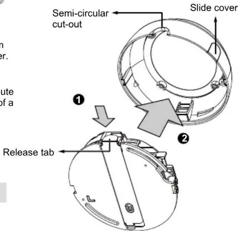
Removing the Dome Cover
- Use one hand to hold the camera bottom and another hand to hold the dome cover. Press the release button.
- Remove the dome cover.
- Remove the slide cover if you want to route cables from the side of camera instead of a hole on the ceiling or wall.

IMPORTANT:
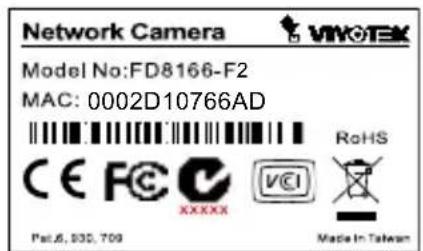
- Record the MAC address before installing the camera.
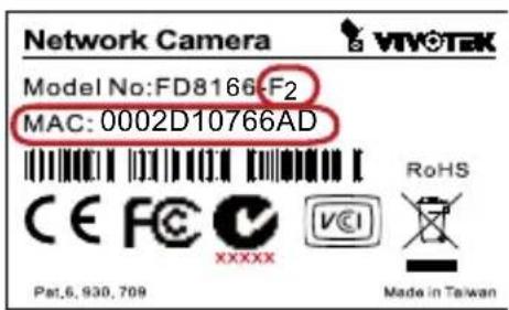
- You can check the model name suffix for the type of lens mounted on your camera. The applicable lens can be:
F2: 2.8mm; F3: 3.6mm; F6: 6mm. The shorter the focal length, the wider the view.

NOTE:
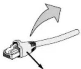
It is recommended to use an Ethernet cable that comes without the strain relief boot. You can remove the boot if your cable comes with one.
natural_image
Illustration of a pliers with an arrow indicating force direction (no text or symbols)Strain relief boot
EN - 4

Mounting the Network Camera - Ceiling or Wall Mount
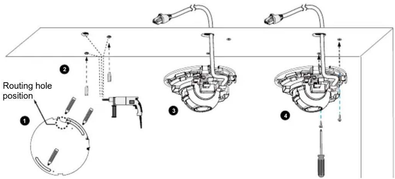
- Use the curved slots on the camera as a template to mark where holes will be drilled on the ceiling. Drill two holes into the ceiling; and hammer in the plastic anchors.
- Drill another hole if you want to route cables through the ceiling or wall.
- Connect and route an Ethernet cable through the ceiling or wall.
- Attach the Network Camera to the ceiling using two included screws.
natural_image
Diagram of a cable or connector with a pipe and connector, showing directional flow (no text or symbols)
NOTE:
- Do not completely tighten the mounting screws in the screw slots yet. You may need to turn the camera left or right for a best shooting direction later.
- The camera can only be powered by PoE. There is no DC or AC input connector.
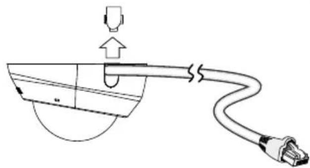
- As shown on the left, you may also route cable from the side.
EN - 5
4 Network Deployment
Power over Ethernet (PoE)
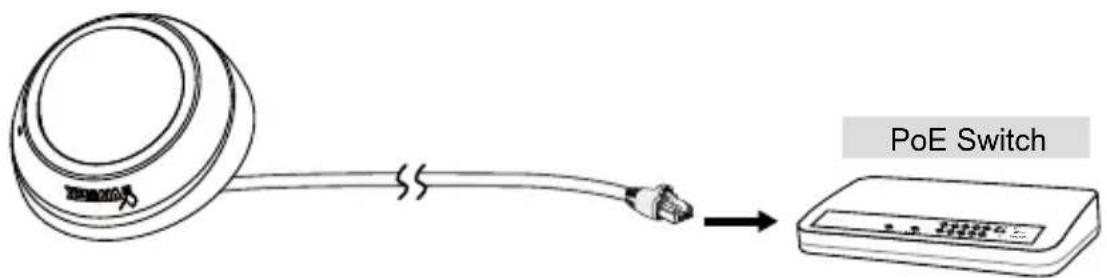
When using a PoE-enabled switch
This Network Camera is PoE-compliant, allowing transmission of power and data via a single Ethernet cable. Follow the below illustration to connect the camera to a PoE-enabled switch via Ethernet cable.
When using a non-PoE switch
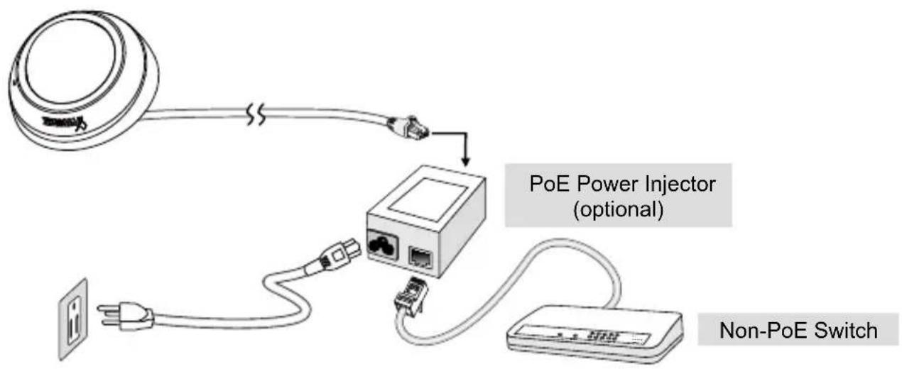
Use a PoE power injector (optional) to connect between the Network Camera and a non-PoE switch.
EN - 6
5 Assigning an IP Address
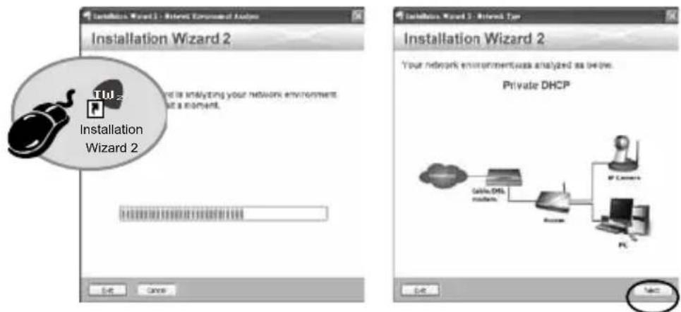
- Install "Installation Wizard 2" from the Software Utility directory on the software CD.
- The program will conduct an analysis of your network environment. After your network is analyzed, please click on the "Next" button to continue the program.
-
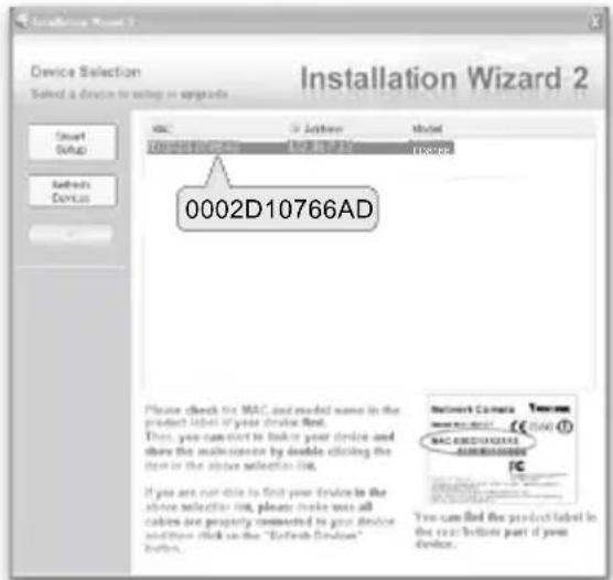
The program will search for VIVOTEK Video Receivers, Video Servers, and Network Cameras on the same LAN.
-
After a brief search, the main installer window will pop up. Double-click on the MAC address that matches the one printed on the camera label or the S/N number on the package box label to open a browser management session with the Network Camera.
EN - 7
6
Ready to Use
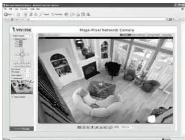
- A browser session with the Network Camera should prompt as shown below.
- You should be able to see live video from your camera. You may also install the 32-channel recording software from the software CD in a deployment consisting of multiple cameras. For its installation details, please refer to its related documents.
natural_image
Black-and-white interior view of a modern office building (no visible text or symbols on main scene)For further setup, please refer to the user's manual on the software CD.
7 Adjusting the Lens

WARNING
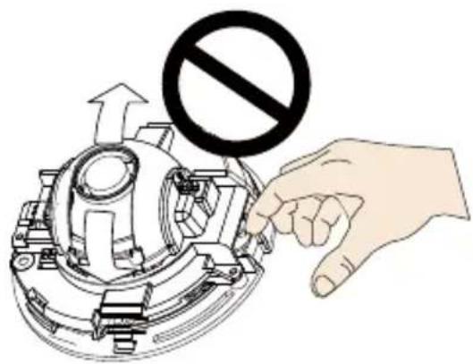
Do not use your hands to tune the lens module's tilt angle. Doing so will damage the delicate tilt mechanism.
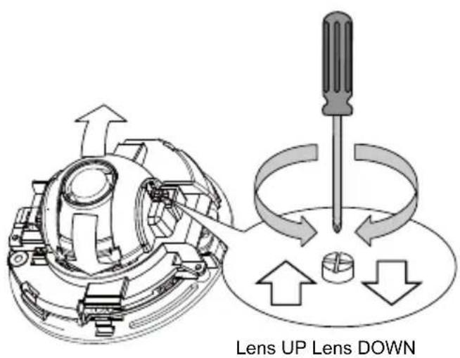
- Tighten the camera's mounting screws after you change the horizontal shooting direction.
- There is a tilt adjustment screw near the lens module. Use a #0, #1, or #2 Phillips screwdriver to turn the screw and the lens will move upwards or downwards.
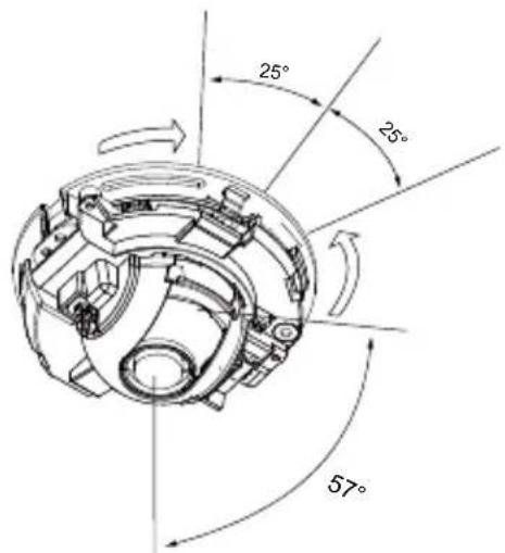
- You may also tune the camera's horizontal orientation by turning it along its curved screw slots.
EN - 9
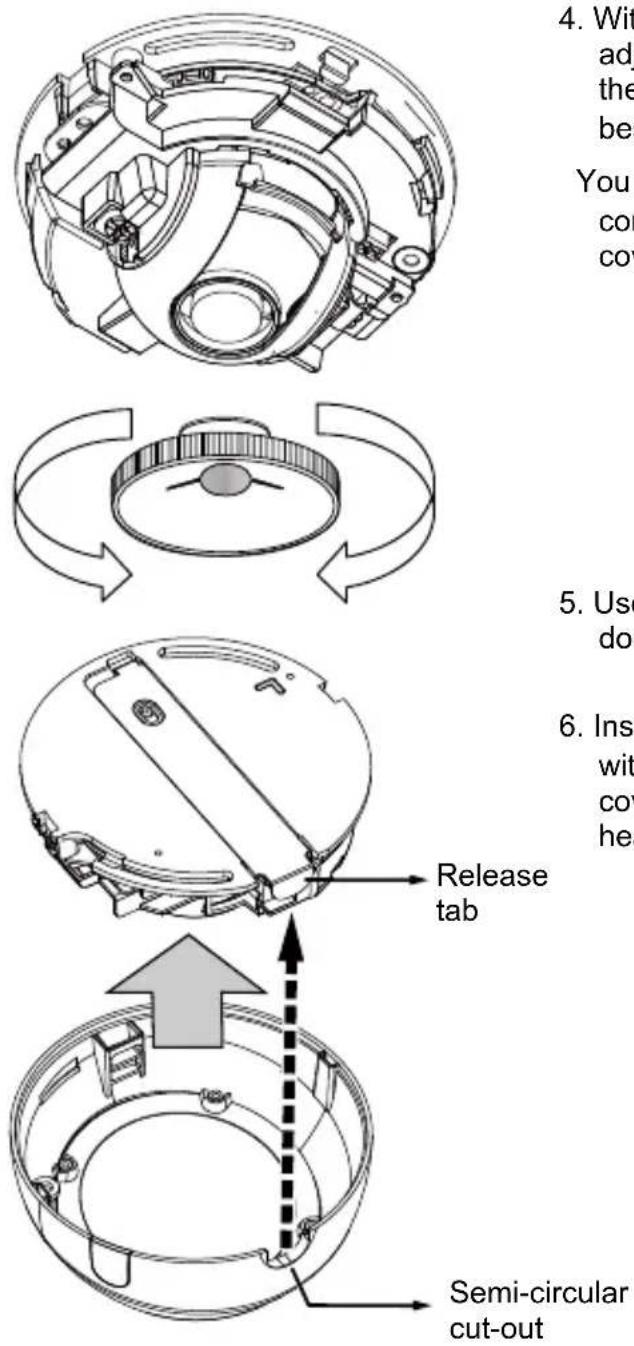
- With a live video feed, you can place the included focus adjustment tool carefully on the lens, and use it to turn the lens clockwise or counter-clockwise to adjust to the best image focus.
You may try tuning the focus slightly closer due to the concern that focus might be changed when the dome cover is installed.
-
Use a piece of clean cotton cloth to hold and install the dome cover.
-
Install dome cover by aligning the semi-circular cut-out with the release tab. Press on both ends of the dome cover for it to snap into place. A "click" sound should be heard when it is properly installed.
EN - 10
P/N:625020901G Rev. 1.1
All specifications are subject to change without notice.
Copyright © 2013 VIVOTEK INC. All rights reserved.

VIVOTEK
VIVOTEK INC.
6F, No.192, Lien-Cheng Rd., Chung-Ho, New Taipei City, 235, Taiwan, R.O.C.
T: +886-2-82455282 | F: +886-2-82455532 | E: sales@vivotek.com
VIVOTEK USA, INC.
2050 Ringwood Avenue, San Jose, CA 95131
| T: 408-773-8686 | F: 408-773-8298 | E: salesusa@vivotok.com
- Warning Before Installation
- Package Contents
- NOTE:
- Physical Description
- 3
- Hardware Installation
- Removing the Dome Cover
- IMPORTANT:
- Mounting the Network Camera - Ceiling or Wall Mount
- Network Deployment
- Power over Ethernet (PoE)
- When using a PoE-enabled switch
- When using a non-PoE switch
- Assigning an IP Address
- 6
- Ready to Use
- Adjusting the Lens
- WARNING
Brand : Vivotek
Model : FD8166-F3
Category : Security Camera