
FD8166-F6 - Security Camera Vivotek - Free user manual and instructions
Find the device manual for free FD8166-F6 Vivotek in PDF.


| Product Type | Indoor Network Fixed Dome Camera |
| Model | FD8166-F6 (Lens f=6mm) |
| Image Sensor | 1/2.7" Progressive CMOS |
| Maximum Resolution | 1920x1080 (2MP) |
| Lens Type | Fixed-focal, F1.6 |
| Field of View | 56° (H) x 31° (V) x 64° (D) |
| Minimum Illumination | 0.18 Lux (50 IRE) |
| Shutter Time | 1/5 sec to 1/32,000 sec |
| Pan / Tilt Range | Pan: 45° / Tilt: 33°~90° |
| ePTZ Zoom | 48x digital zoom (4x on IE plug-in, 12x built-in) |
| Video Compression | H.264 & MJPEG |
| Max Frame Rate | 15fps @ 1920x1080 (H.264/MJPEG) |
| Audio | Built-in microphone, G.711 compression, 5m range |
| Network Interface | 10Base-T/100BaseTX Ethernet (RJ-45) |
| Power Supply | Power over Ethernet (PoE) IEEE 802.3af Class 1 |
| Power Consumption | Max 2.9W |
| Dimensions | ∅90mm x 50mm |
| Weight | 144g (net) |
| Operating Temperature | 0°C to 50°C (32°F to 122°F) |
| On-board Storage | MicroSD/SDHC/SDXC card slot |
| Intelligent Video | Triple-window motion detection, tampering detection |
| Alarm Triggers | Motion, manual, digital input, periodic, system boot, recording notification, tampering |
| Alarm Events | HTTP, SMTP, FTP, NAS server file upload |
| Safety Certifications | CE, LVD, FCC Class B, VCCI, C-Tick |
| Maintenance & Cleaning | Clean dome cover with a clean, soft cotton cloth. Avoid using harsh chemicals. |
| Spare Parts & Repairability | Contact VIVOTEK or authorized dealers for spare parts and repair services. |
Frequently Asked Questions - FD8166-F6 Vivotek
User questions about FD8166-F6 Vivotek
0 question about this device. Answer the ones you know or ask your own.
Ask a new question about this device
Download the instructions for your Security Camera in PDF format for free! Find your manual FD8166-F6 - Vivotek and take your electronic device back in hand. On this page are published all the documents necessary for the use of your device. FD8166-F6 by Vivotek.
USER MANUAL FD8166-F6 Vivotek
2MP • Stylish Design • Easy Installation

Rev. 1.0
Table of Contents
Overview......4
Revision History 4
Read Before Use....5
Package Contents 5
Symbols and Statements in this Document....5
Physical Description....6
Installation 8
Network Deployment....10
Software Installation....12
Ready to Use....13
Accessing the Network Camera 16
Using Web Browsers 16
Using RTSP Players....19
Using 3GPP-compatible Mobile Devices....20
Using VIVOTEK Recording Software 21
Main Page 22
Go to....26
Client Settings 27
Configuration....31
System > General settings 32
System > Maintenance....40
Media > Image 44
Media > Video 50
Media > Video 51
Media >Audio....55
Network > General settings 56
Network > Streaming protocols 63
Network > SNMP (Simple Network Management Protocol)....72
Security > User Account....73
Security > HTTPS (Hypertext Transfer Protocol over SSL) 74
Security > Access List 82
PTZ > PTZ settings 87
Event > Event settings....91
Applications > Motion detection....104
Applications > Digital Input....107
Applications > Tampering detection 107
Recording > Recording settings 108
Local storage > SD card management.... 113
Local storage > Content management 114
Appendix 117
URL Commands for the Network Camera....117
Technical Specifications 193
Technology License Notice....194
Electromagnetic Compatibility (EMC)....195
Overview
VIVOTEK FD8166 is the world's smallest network fixed dome camera. With installation as easy as one-two-three and Power over Ethernet (PoE) functionality, setup time is completed in less than 120 seconds, making installation quick and easy.
The FD8166 features a 2-Megapixel sensor enabling viewing resolution of 1920x1080 at 15 fps, and also supports the industry-standard H.264 compression technology, drastically reducing file sizes and conserving valuable network bandwidth. With MJPEG compatibility also included, video streams can also be transmitted in any of these formats for versatile applications.
Designed with selectable focal lengths, FD8166 can be used in various environments, including but not limited to offices, elevators, campus, chain stores, boutique stores and health care facilities. At the size of only 90 mm in diameter, VIVOTEK FD8166 is truly an all-in-one surveillance solution that meets a wide variety of needs for indoor surveillance. The package also includes VIVOTEK's 32-channel recording software. With all this and more, the FD8166 is the ideal solution for your surveillance needs.
Revision History
■ Rev. 1.0: Initial release
Read Before Use
The use of surveillance devices may be prohibited by law in your country. The Network Camera is not only a high-performance web-ready camera but can also be part of a flexible surveillance system. It is the user's responsibility to ensure that the operation of such devices is legal before installing this unit for its intended use.
It is important to first verify that all contents received are complete according to the Package Contents listed below. Take note of the warnings in the Quick Installation Guide before the Network Camera is installed; then carefully read and follow the instructions in the Installation chapter to avoid damage due to faulty assembly and installation. This also ensures the product is used properly as intended.
The Network Camera is a network device and its use should be straightforward for those who have basic networking knowledge. It is designed for various applications including video sharing, general security/surveillance, etc. The Configuration chapter suggests ways to best utilize the Network Camera and ensure proper operations. For creative and professional developers, the URL Commands of the Network Camera section serves as a helpful reference to customizing existing homepages or integrating with the current web server.
Package Contents
■ FD8166
■ Screws / Plastic Anchors
■ Focus adjustment tool
■ Software CD
■ Warranty Card
■ Quick Installation Guide
Symbols and Statements in this Document

INFORMATION: provides important messages or advices that might help prevent inconvenient or problem situations.

NOTE: Notices provide guidance or advices that are related to the functional integrity of the machine.

Tips: Tips are useful information that helps enhance or facilitae an installation, function, or process.

WARNING! or IMPORTANT!: These statements indicate situations that can be dangerous or hazardous to the machine or you.

Electrical Hazard: This statement appears when high voltage electrical hazards might occur to an operator.
Physical Description
Outer View
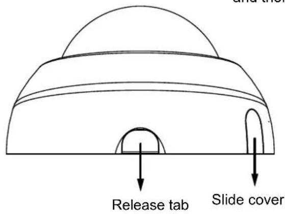
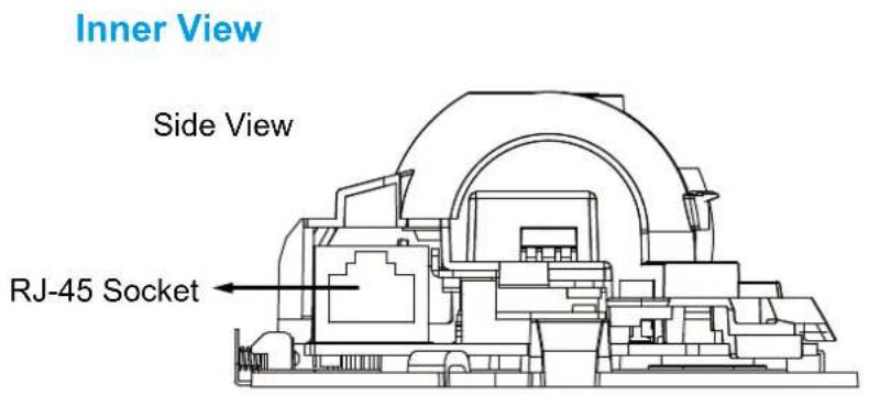
Leave the slide cover in place if you route cables through the bottom and then through a hole on the ceiling or wall.
Digital Input Diagram
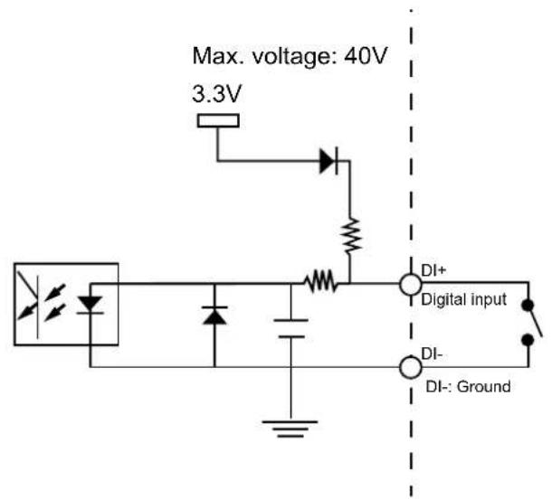
Please refer to the following illustration for the connection method.
Hardware Reset
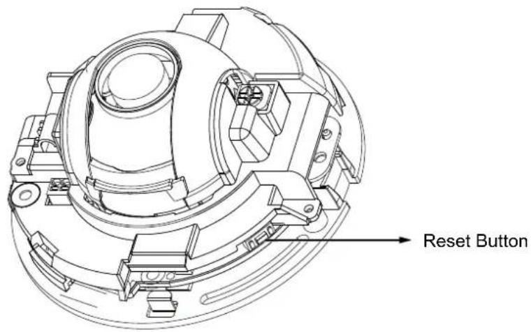
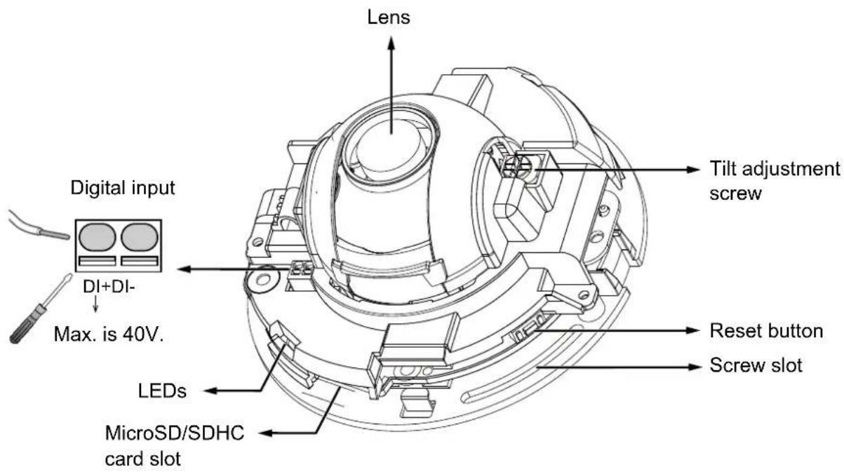
The reset button is used to reset the system or restore the factory default settings. Sometimes resetting the system can return the camera to normal operation. If the system problems remain after reset, restore the factory settings and install again.
Reset: Press and release the reset button. Wait for the Network Camera to reboot.
Restore: Press and hold the recessed reset button until the status LED rapidly blinks. Note that all settings will be restored to factory default. Upon successful restore, the status LED will blink green and red during normal operation.
Micro SD/SDHC Card Capacity
This network camera is compliant with Micro SD/SDHC 32GB / 16GB / 8GB and other preceding standard SD cards.
Installation
Removing Dome Cover
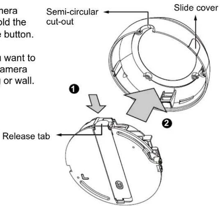
- Use one hand to hold the camera bottom and another hand to hold the dome cover. Press the release button.
- Remove the dome cover.
- Remove the slide cover if you want to route cables from the side of camera instead of a hole on the ceiling or wall.

IMPORTANT!
- Record the MAC address before installing the camera.
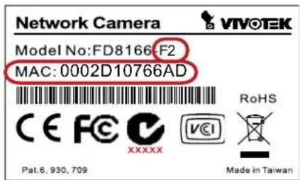
- You can check the model name suffix for the type of lens mounted on your camera. The applicable lens can be:
F2: 2.5mm; F3: 3.6mm; F6: 6mm; F8: 8mm; F12: 12mm. The shorter the focal length, the wider the view.

NOTE:
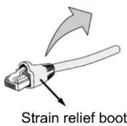
It is recommended to use an Ethernet cable that comes without the strain relief boot. You can remove the boot if your cable comes with one.
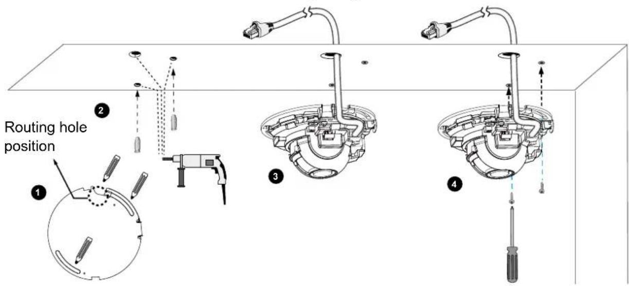
Mounting the Network Camera - Ceiling or Wall Mount
- Use the curved slots on the camera as a template to mark where holes will be drilled on the ceiling. Drill two holes into the ceiling; and hammer in the plastic anchors.
- Drill another hole if you want to route cables through the ceiling or wall.
- Connect and route an Ethernet cable through the ceiling or wall.
- Attach the Network Camera to the ceiling using two included screws.

NOTE:
natural_image
Diagram of a cable or connector with a connector inserted into a housing, showing internal components and flow direction (no text or symbols)- Do not completely tighten the mounting screws in the screw slots yet. You may need to turn the camera left or right for a best shooting direction later.
- The camera can only be powered by PoE. There is no DC or AC input connector.
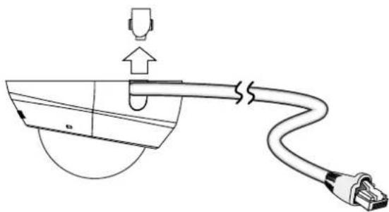
- As shown on the left, you may also route cable from the side.
LED Definitions
| Item | LED Status Description | |
| 1 Steady Red Power on and system boot- | ing | |
| 2 Steady Red + blinking Green every 1 sec. (Green LED on for 1 sec and off for another) | Network heartbeat | |
| 3 Blinking Red every 0.15 sec. + Blinking Green every 1 sec.(Red LED on for 0.15 sec. and Green LED on for 1 sec. and off for another) | Upgrading firmware | |
| 4 Blinking Red every 0.15 sec. + blinking Green every 0.15 sec. | Restoring defaults | |
Network Deployment
General Connection (without PoE)
Power over Ethernet (PoE)
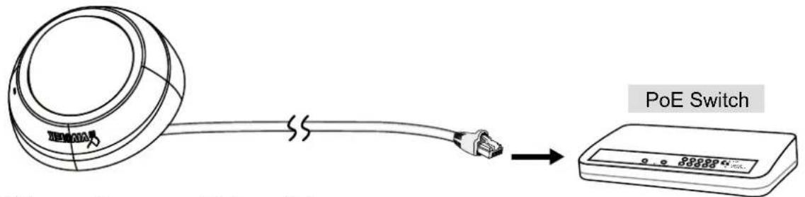
When using a PoE-enabled switch
This Network Camera is PoE-compliant, allowing transmission of power and data via a single Ethernet cable. Follow the below illustration to connect the camera to a PoE-enabled switch via Ethernet cable.
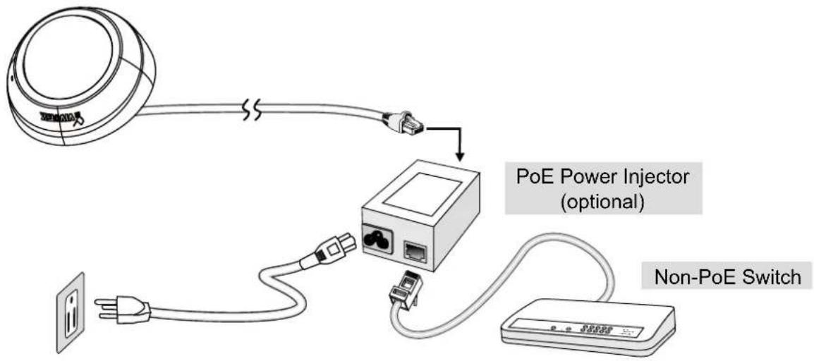
When using a non-PoE switch
Use a PoE power injector (optional) to connect between the Network Camera and a non-PoE switch.
Internet connection via a router
Before setting up the Network Camera over the Internet, make sure you have a router and follow the steps below.
- Connect your Network Camera behind a router, the Internet environment is illustrated below. Regarding how to obtain your IP address, please refer to Software Installation on page 12 for details.
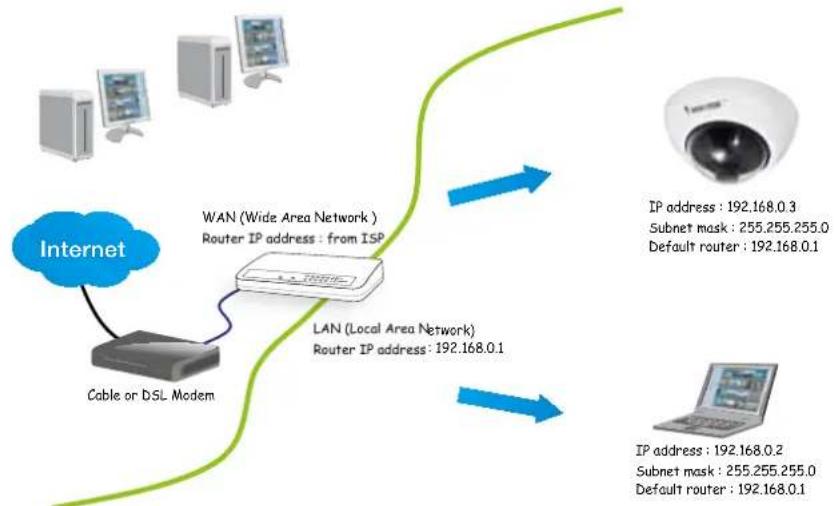
flowchart
graph TD
    A["Internet"] --> B["Cable or DSL Modem"]
    B --> C["WAN (Wide Area Network) Router IP address: from ISP"]
    C --> D["LAN (Local Area Network) Router IP address: 192.168.0.1"]
    D --> E["IP address: 192.168.0.3\nSubnet mask: 255.255.255.0\nDefault router: 192.168.0.1"]
    D --> F["IP address: 192.168.0.2\nSubnet mask: 255.255.255.0\nDefault router: 192.168.0.1"]
- In this case, if the Local Area Network (LAN) IP address of your Network Camera is 192.168.0.3, please forward the following ports for the Network Camera on the router.
■ HTTP port: default is 80
■ RTSP port: default is 554
■ RTP port for audio: default is 5558
■ RTCP port for audio: default is 5559
■ RTP port for video: default is 5556
■ RTCP port for video: default is 5557
If you have changed the port numbers on the Network page, please open the ports accordingly on your router. For information on how to forward ports on the router, please refer to your router's user's manual.
- Find out the public IP address of your router provided by your ISP (Internet Service Provider). Use the public IP and the secondary HTTP port to access the Network Camera from the Internet. Please refer to Network Type on page 56 for details.
Internet connection with static IP
Choose this connection type if you are required to use a static IP for the Network Camera. Please refer to LAN setting on page 56 for details.
Internet connection via PPPoE (Point-to-Point over Ethernet)
Choose this connection type if you are connected to the Internet via a DSL Line. Please refer to PPPoE on page 57 for details.
Software Installation
Installation Wizard 2 (IW2), free-bundled software included on the product CD, helps you set up your Network Camera on the LAN.
- Install IW2 under the Software Utility directory from the software CD. Double-click the IW2 shortcut on your desktop to launch the program.
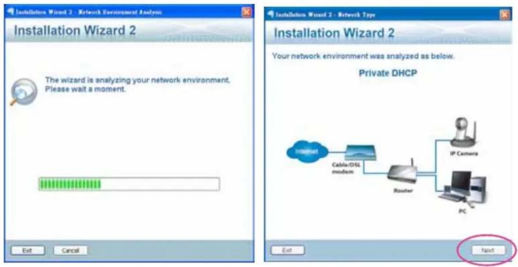
- The program will conduct an analysis of your network environment. After your network environment is analyzed, please click Next to continue the program.
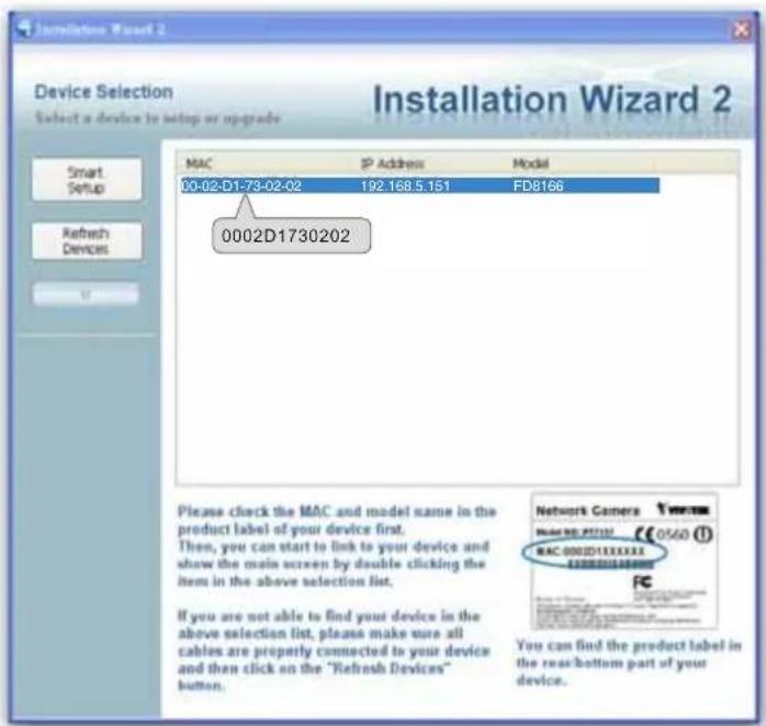
- The program will search for all VIVOTEK network devices on the same LAN.
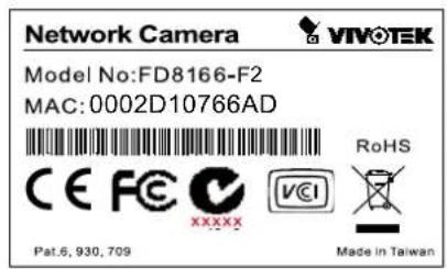
- After a brief search, the installer window will prompt. Click on the MAC and model name that matches the one printed on the product label. You can then double-click on the address to open a management session with the Network Camera.
Ready to Use
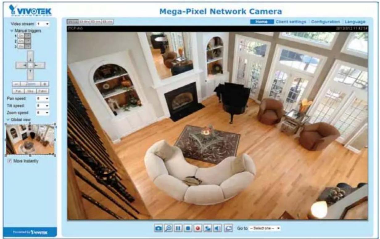
- A browser session with the Network Camera should prompt as shown below.
- You should be able to see live video from your camera. You may also install the 32-channel recording software from the software CD in a deployment consisting of multiple cameras. For its installation details, please refer to its related documents.
Adjusting the Lens

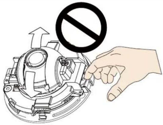
WARNING!
Do not use your hands to tune the lens module's tilt angle. Doing so will damage the delicate tilt mechanism.
-
Tighten the camera's mounting screws after you change the horizontal shooting direction.
-
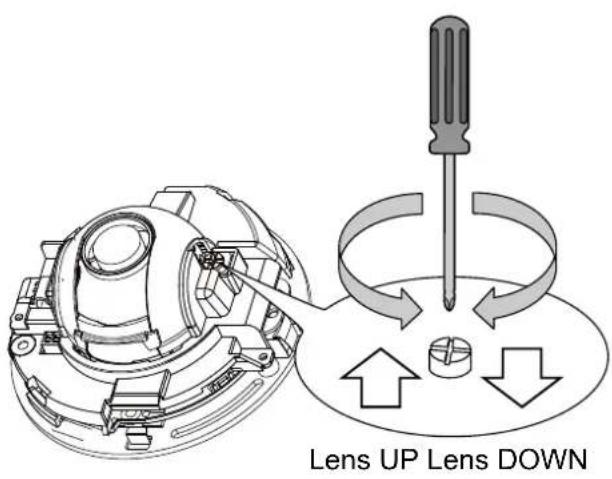
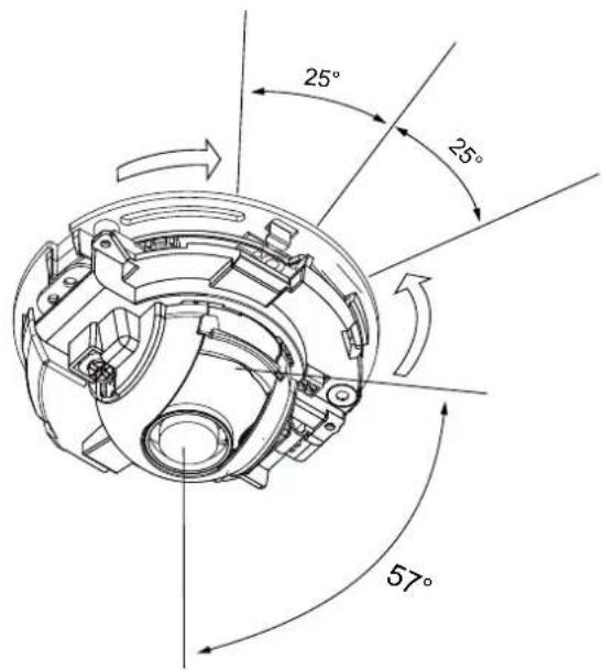
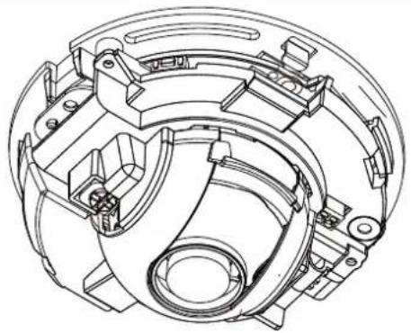
There is a tilt adjustment screw near the lens module. Use a #0, #1, or #2 Phillips screwdriver to turn the screw and the lens will move upwards or downwards.
-
You may also tune the camera's horizontal orientation by turning it along its curved screw slots.
natural_image
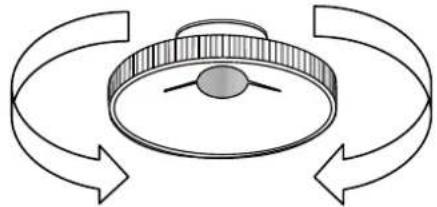
Technical line drawing of a mechanical component with no visible text or symbols- With a live video feed, you can place the included focus adjustment tool carefully on the lens, and use it to turn the lens clockwise or counterclockwise to adjust to the best image focus.
You may try tuning the focus slightly closer due to the concern that focus might be changed when the dome cover is installed.
natural_image
Diagram of a circular mechanical component with three curved arrows indicating rotational motion (no text or symbols)-
Use a piece of clean cotton cloth to hold and and install the dome cover.
-
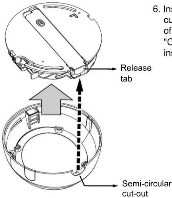
Install dome cover by aligning the semi-circular cut-out with the release tab. Press on both ends of the dome cover for it to snap into place. A "Click" sound should be heard when it is properly installed.
Accessing the Network Camera
This chapter explains how to access the Network Camera through web browsers, RTSP players, 3GPP-compatible mobile devices, and VIVOTEK recording software.
Using Web Browsers
Use Installation Wizard 2 (IW2) to access the Network Cameras on LAN.
If your network environment is not a LAN, follow these steps to access the Network Camera:
- Launch your web browser (e.g., Microsoft® Internet Explorer, Mozilla Firefox, or Netscape).
- Enter the IP address of the Network Camera in the address field. Press Enter.
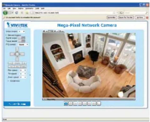
- The live video will be displayed in your web browser.
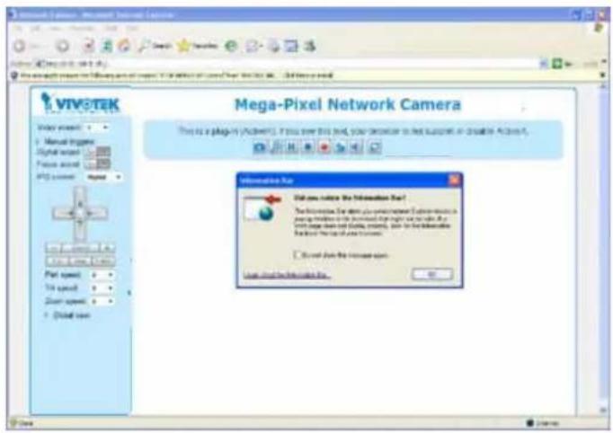
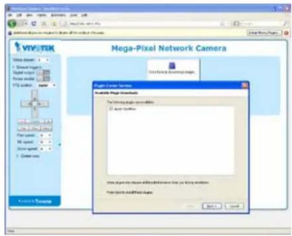
- If it is the first time installing the VIVOTEK network camera, an information bar will pop up as shown below. Follow the instructions to install the required plug-in on your computer.

NOTE:
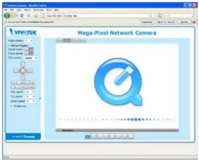
For Mozilla Firefox or Netscape users, your browser will use Quick Time to stream the live video. If you don't have Quick Time on your computer, please download it first, then launch the web browser.
▶ By default, the Network Camera is not password-protected. To prevent unauthorized access, it is highly recommended to set a password for the Network Camera.
For more information about how to enable password protection, please refer to Security on page 73.
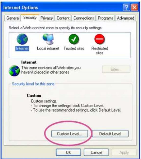
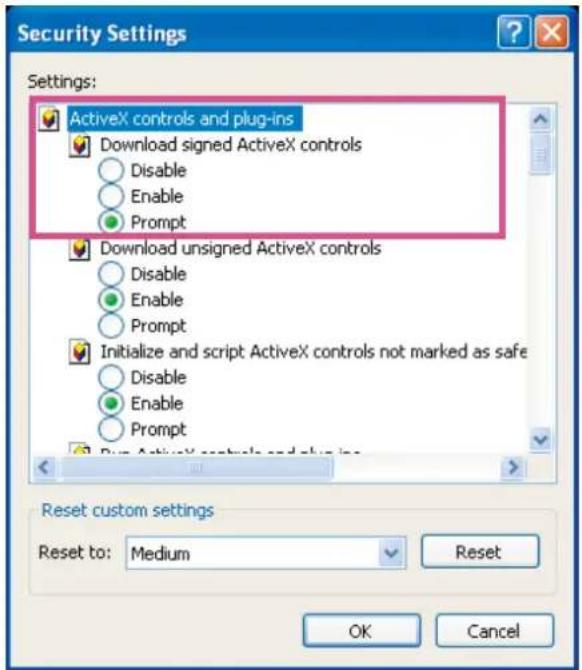
If you see a dialog box indicating that your security settings prohibit running ActiveX Controls, please enable the ActiveX ^ Controls for your browser.
- Choose Tools > Internet Options > Security > Custom Level.
- Look for Download signed ActiveX® controls; select Enable or Prompt. Click OK.
- Refresh your web browser, then install the ActiveXcontrol. Follow the instructions to complete installation.

IMPORTANT!
- Currently the Network Camera utilizes 32-bit ActiveX plugin. You CAN NOT open a management/view session with the camera using a 64-bit IE browser.
- If you encounter this problem, try execute the lexlore.exe program from C:\Windows\SysWOW64. A 32-bit version of IE browser will be installed.
- On Windows 7, the 32-bit explorer browser can be accessed from here:
C:\Program Files (x86)\Internet Explorer\iexplore.exe
- If you open a web session from the IW2 utility, a 32-bit IE browser will be opened.

Tips
- The onscreen Java control can malfunction under the following situations: A PC connects to different cameras that are using the same IP address (or the same camera running different firmware versions). Removing your browser cookies will solve this problem.
Using RTSP Players
To view the MPEG-4 streaming media using RTSP players, you can use one of the following players that support RTSP streaming.

Quick Time Player
VLC Player
- Launch the RTSP player.
- Choose File > Open URL. A URL dialog box will pop up.
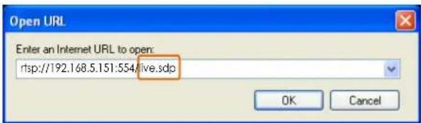
- The address format is rtsp://
: /
As most ISPs and players only allow RTSP streaming through port number 554, please set the RTSP port to 554. For more information, please refer to RTSP Streaming on page 64.
For example:
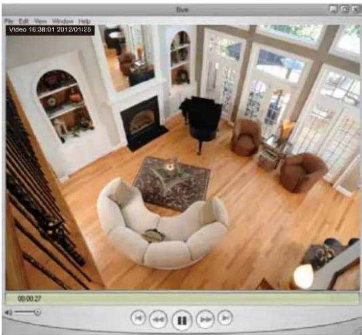
- The live video will be displayed in your player.
For more information on how to configure the RTSP access name, please refer to RTSP Streaming on page 64 for details.
natural_image
Interior view of a modern living room with wooden flooring, armchairs, and large windows (no visible text or symbols)
NOTE:
Quick Time player only supports playback of H.264 stream, and not the MJPEG stream. In terms of audio codec, Quick Time only supports AAC. Since this camera supports G.711 codec, audio is not available on Quick Time.
VLC player supports H.264/MPEG-4/MJPEG, and all audio codecs supported by all VIVOTEK's cameras.
Using 3GPP-compatible Mobile Devices
To view the streaming media through 3GPP-compatible mobile devices, make sure the Network Camera can be accessed over the Internet. For more information on how to set up the Network Camera over the Internet, please refer to Setup the Network Camera over the Internet on page 10.
To utilize this feature, please check the following settings on your Network Camera:
-
Because most players on 3GPP mobile phones do not support RTSP authentication, make sure the authentication mode of RTSP streaming is set to disable.
For more information, please refer to RTSP Streaming on page 64. -
As the bandwidth on 3G networks is limited, you will not be able to use a large video size. Please set the video and audio streaming parameters as listed below.
For more information, please refer to Stream settings on page 50.
| Video Mode MPEG-4 | |
| Frame size 176 x 144 | |
| Maximum frame rate 5 fps | |
| Intra frame period 1S | |
| Video quality (Constant bit rate) 40kbps | |
| Audio type (GSM-AMR) 12.2kbps | |
-
As most ISPs and players only allow RTSP streaming through port number 554, please set the RTSP port to 554. For more information, please refer to RTSP Streaming on page 64.
-
Launch the player on the 3GPP-compatible mobile devices (e.g., Real Player).
-
Type the following URL commands into the player.
The address format is rtsp://
For example:
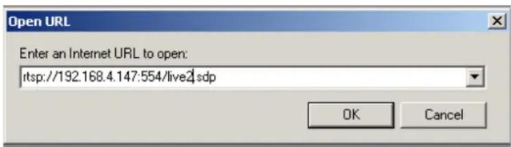
You can configure Stream #2 into the suggested stream settings as listed above for live viewing on a mobile device.
Using VIVOTEK Recording Software
The product software CD also contains an ST7501 recording software, allowing simultaneous monitoring and video recording for multiple Network Cameras. Please install the recording software; then launch the program to add the Network Camera to the Channel list. For detailed information about how to use the recording software, please refer to the user's manual of the software or download it from http://www.vivotek.com.
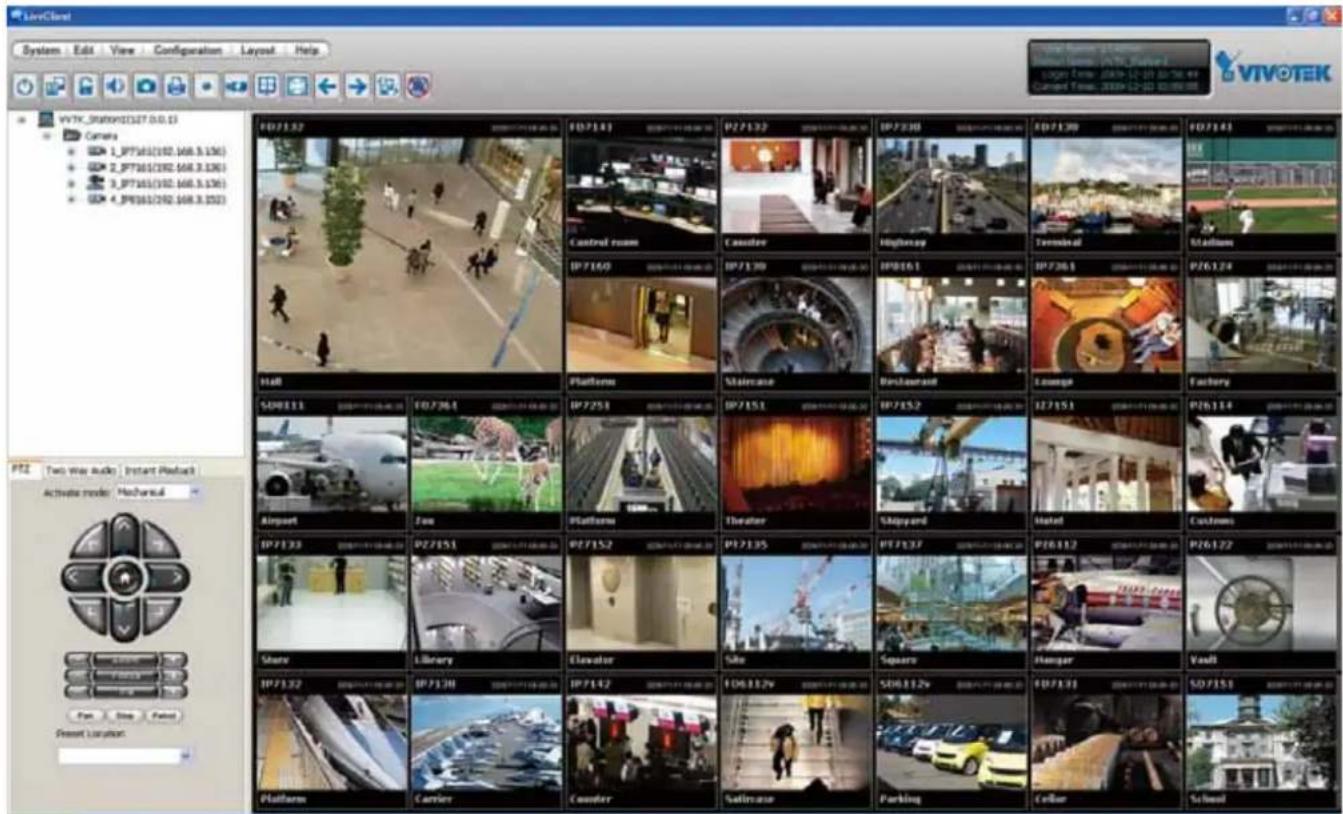
Main Page
This chapter explains the layout of the main page. It is composed of the following sections: VIVOTEK INC. Logo, Host Name, Camera Control Area, Configuration Area, Menu, and Live Video Window.
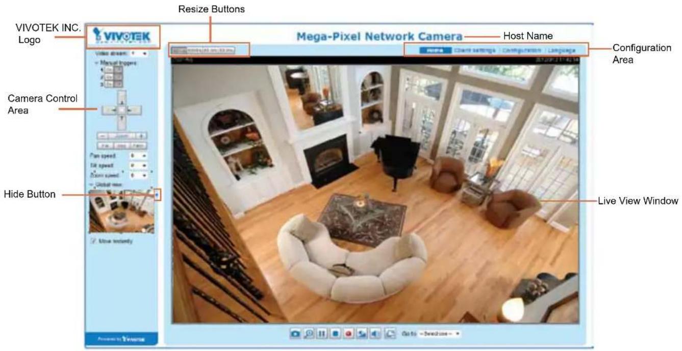
VIVOTEK INC. Logo
Click this logo to visit the VIVOTEK website.
Host Name
The host name can be customized to fit your needs. For more information, please refer to System on page 32.
Camera Control Area
Video Stream: This Network Camera supports multiple streams (stream 1 \~ 2) simultaneously. You can select either one for live viewing. For more information about multiple streams, please refer to page 81 for detailed information.
Manual Trigger: Click to enable/disable an event trigger manually. Please configure an event setting on Application page before enable this function. A total of 3 event settings can be configured. For more information about event setting, please refer to page 90. If you want to hide this item on the homepage, please go to Configuration> System > Homepage Layout > General settings > Customized button to deselect "show manual trigger button".
Configuration Area
Client Settings: Click this button to access the client setting page. For more information, please refer to Client Settings on page 27.
Configuration: Click this button to access the configuration page of the Network Camera. It is suggested that a password be applied to the Network Camera so that only the administrator can configure the Network Camera. For more information, please refer to Configuration on page 31.
Language: Click this button to choose a language for the user interface. Language options are available in: English, Deutsch, Español, Français, Italiano, 日本語, Português, 簡体中文, and 繁體中文. Please note that you can also change a language on the Configuration page; please refer to page 31.
Hide Button
You can click the hide button to hide the control panel or display the control panel.
Resize Buttons

Click the Auto button, the video cell will resize automatically to fit the monitor. Click 100% is to display the original homepage size. Click 50% is to resize the homepage to 50% of its original size. Click 25% is to resize the homepage to 25% of its original size.
Live Video Window
■ The following window is displayed when the video mode is set to H.264 / MPEG-4:
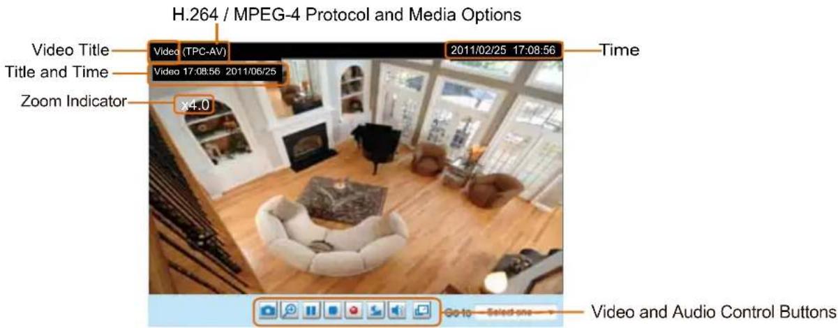
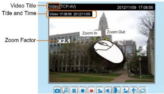
Video Title: The video title can be configured. For more information, please refer to Video Settings on page 50.
H.264 / MPEG-4 Protocol and Media Options: The transmission protocol and media options for H.264 / MPEG-4 video streaming. For further configuration, please refer to Client Settings on page 27.
Time: Display the current time. For further configuration, please refer to Media > Image > Genral settings on page 44.
Title and Time: The video title and time can be stamped on the streaming video. For further configuration, please refer to Media > Image > General settings on page 44.
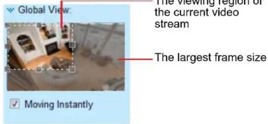
Global View: Click on this item to display the Global View window. The Global View window contains a full view image (the largest frame size of the captured video) and a floating frame (the viewing region of the current video stream). The floating frame allows users to control the e-PTZ function (Electronic Pan/Tilt/Zoom). For more information about e-PTZ operation, please refer to E-PTZ Operation on page 87. For more information about how to set up the viewing region of the current video stream, please refer to page 87.
PTZ Panel: This Network Camera supports both "digital" (e-PTZ) pan/tilt/zoom control. Please refer to PTZ settings on page 87 for detailed information.
Video and Audio Control Buttons: Depending on the Network Camera model and Network Camera configuration, some buttons may not be available.
Snapshot: Click this button to capture and save still images. The captured images will be displayed in a pop-up window. Right-click the image and choose Save Picture As to save it in JPEG (*.jpg) or BMP (*.bmp) format.
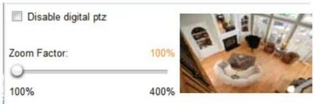
Digital Zoom: Click and uncheck "Disable digital zoom" to enable the zoom operation. The navigation screen indicates the part of the image being magnified. To control the zoom level, drag the slider bar. To move to a different area you want to magnify, drag the navigation screen.
Pause: Pause the transmission of the streaming media. The button becomes the ▶ Resume button after clicking the Pause button.
Stop: Stop the transmission of the streaming media. Click the Resume button to continue transmission.
- Start MP4 Recording: Click this button to record video clips in MP4 file format to your computer. Press the - Stop MP4 Recording button to end recording. When you exit the web browser, video recording stops accordingly. To specify the storage destination and file name, please refer to MP4 Saving Options on page 28 for details.
Volume: When the Mute function is not activated, move the slider bar to adjust the volume on the local computer.
Mute: Turn off the volume on the local computer. The button becomes the Audio On button after clicking the Mute button.
Full Screen: Click this button to switch to full screen mode. Press the "Esc" key to switch back to normal mode.
■ The following window is displayed when the video mode is set to MJPEG:
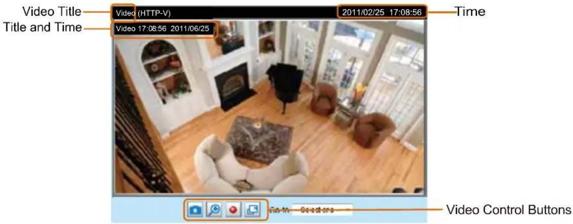
Video Title: The video title can be configured. For more information, please refer to Media > Image on page 44.
Time: Display the current time. For more information, please refer to Media > Image on page 44.
Title and Time: Video title and time can be stamped on the streaming video. For more information, please refer to Media > Image on page 44.
Video and Audio Control Buttons: Depending on the Network Camera model and Network Camera configuration, some buttons may not be available.
Snapshot: Click this button to capture and save still images. The captured images will be displayed in a pop-up window. Right-click the image and choose Save Picture As to save it in JPEG (*.jpg) or BMP (*.bmp) format.
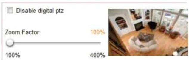
Digital Zoom: Click and uncheck "Disable digital zoom" to enable the zoom operation. The navigation screen indicates the part of the image being magnified. To control the zoom level, drag the slider bar. To move to a different area you want to magnify, drag the navigation screen.
Start MP4 Recording: Click this button to record video clips in MP4 file format to your computer. Press the Stop MP4 Recording button to end recording. When you exit the web browser, video recording stops accordingly. To specify the storage destination and file name, please refer to MP4 Saving Options on page 28 for details.
Full Screen: Click this button to switch to full screen mode. Press the "Esc" key to switch back to normal mode.
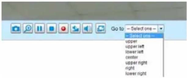
Go to
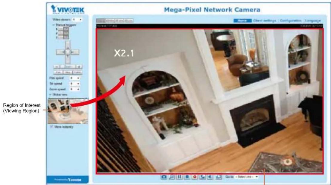
If you configured and chose to display a smaller region of interest from out of a maximum image frame, you can configure different areas within the frame as preset points, and use this menu to move to a location.
A zoom indicator will be displayed on the Home page when you zoom in/out on the live viewing window as shown below. You may zoom in/out on the image by scrolling the mouse wheel inside the live viewing window, and the maximum zoom in will be up to 4 times.
Client Settings
This chapter explains how to select the stream transmission mode and saving options on the local computer. When completed with the settings on this page, click Save on the page bottom to enable the settings.
H.264 Media Options
H.264 Media Options
Video and Audio
Video Only
Audio Only
Select to stream video or audio data or both. This is enabled only when the video mode is set to H.264.
H.264 Protocol Options
H.264 Protocol Options
○ UDP Unicast
○ UDP Multicast
TCP
HTTP
Depending on your network environment, there are four transmission modes of H.264 streaming:
UDP unicast: This protocol allows for more real-time audio and video streams. However, network packets may be lost due to network burst traffic and images may be broken. Activate UDP connection when occasions require time-sensitive responses and the video quality is less important. Note that each unicast client connecting to the server takes up additional bandwidth and the Network Camera allows up to ten simultaneous accesses.
UDP multicast: This protocol allows multicast-enabled routers to forward network packets to all clients requesting streaming media. This helps to reduce the network transmission load of the Network Camera while serving multiple clients at the same time. Note that to utilize this feature, the Network Camera must be configured to enable multicast streaming at the same time. For more information, please refer to RTSP Streaming on page 64.
TCP: This protocol guarantees the complete delivery of streaming data and thus provides better video quality. The downside of this protocol is that its real-time effect is not as good as that of the UDP protocol.
HTTP: This protocol allows the same quality as TCP protocol without needing to open specific ports for streaming under some network environments. Users inside a firewall can utilize this protocol to allow streaming data through.
MP4 Saving Options
MP4 saving options
Folder:
D:\Record
Browse...
File name prefix:
CLIP

Add date and time suffix to file name
Users can record live video as they are watching it by clicking Start MP4 Recording on the main page. Here you can specify the storage destination and file name.
Folder: Specify a storage destination for the recorded video files.
File name prefix: Enter the text that will be appended to the front of the video file name.
Add date and time suffix to the file name: Select this option to append the date and time to the end of the file name.
CLIP_20110628-180853


File name prefix
Date and time suffix
The format is: YYYYMMDD_HHMMSS
Local Streaming Buffer Time
Local streaming buffer time

Millisecond
Save
Due to the unsteady bandwidth flow, the live streaming may lag and not be very smoothly. If you enable this option, the live streaming will be stored on the cache memory of the PC having a web session with the camera for a few seconds before being played on the live viewing window. This helps you see the streaming more smoothly. If you enter 3000 Millisecond, the streaming will delay for 3 seconds.
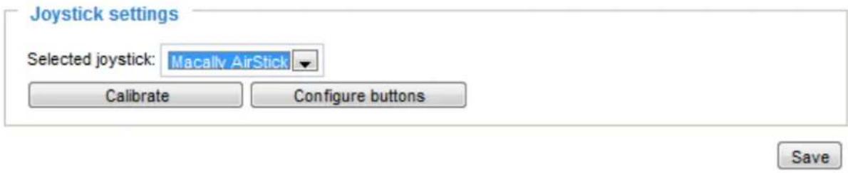
Joystick settings
Enable Joystick
Connect a joystick to a USB port on your management computer. Supported by the plug-in (Microsoft's DirectX), once the plug-in for the web console is loaded, it will automatically detect if there is any joystick on the computer. The joystick should work properly without installing any other driver or software.
Then you can begin to configure the joystick settings of connected devices. Please follow the instructions below to enable joystick settings.
- Select a detected joystick, if there are multiple, from the Selected joystick menu. If your joystick is not detected, if may be defective.
- Click Calibrate or Configure buttons to configure the joystick-related settings.

NOTE:
- If you want to assign Preset actions to your joystick, the preset locations should be configured in advance in the Configuration > PTZ page.
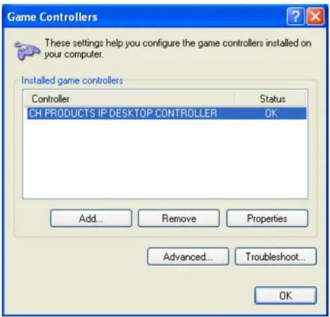
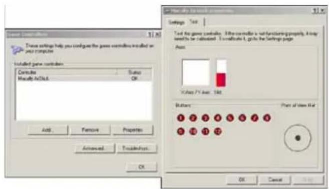
- If your joystick is not working properly, it may need to be calibrated. Click the Calibrate button to open the Game Controllers window located in Microsoft Windows control panel and follow the instructions for trouble shooting.
- The joystick will appear in the Game Controllers list in the Windows Control panel. If you want to check out for your devices, go to the following page: Start -> Control Panel -> Game Controllers.
Buttons Configuration
Click the Configure Buttons button, a window will prompt as shown below. Please follow the steps below to configure your joystick buttons:
- Select a button number from the Button # pull-down menu.
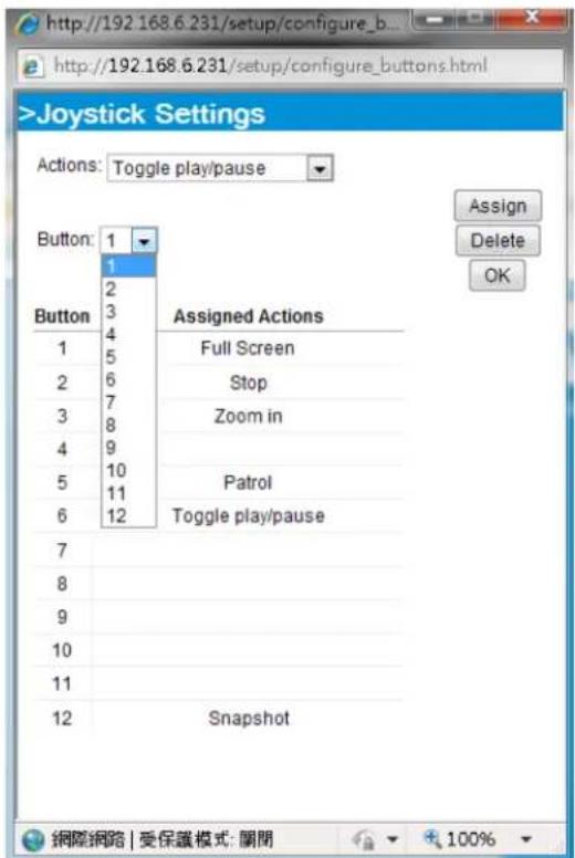

Tips
If you are not sure of the locations of each button, use the Properties window in the Game Controllers utility.
- Select a corresponding action, such as Patrol or Preset#.
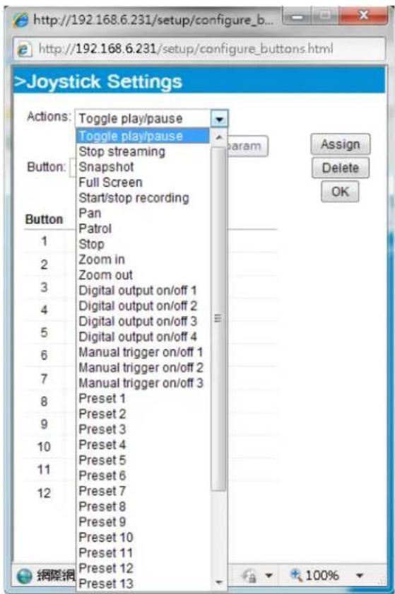
- Click the Assign button to assign an action to the button. You can delete an association by selecting a button number, and then click the Delete button.
Repeat the process until you are done with the configuration of all preferred actions.
The buttons you define should appear on the button list accordingly.
- Please remember to click the Save button on the Client settings page to preserver your settings.
Configuration
Click Configuration on the main page to enter the camera setting pages. Note that only Administrators can access the configuration page.
VIVOTEK offers an easy-to-use user interface that helps you set up your network camera with minimal effort. To simplify the setting procedure, two types of user interfaces are available: Advanced Mode for professional users and Basic Mode for entry-level users. Some advanced functions (PTZ/ Event/ Recording/ Local storage) are not displayed in Basic Mode.
If you want to set up advanced functions, please click [Advanced Mode] on the bottom of the configuration list to quickly switch to Advanced Mode.
In order to simplify the user interface, the detailed information will be hidden unless you click to unfold a functional item. When you click on the first sub-item, the detailed information for the first sub-item will be displayed; when you click on the second sub-item, the detailed information for the second sub-item will be displayed and that of the first sub-item will be hidden.
The following is the interface of the Basic Mode and the Advanced Mode:
Basic Mode
![VIVOTEK www.vivotek.com Home Client settings Configuration Language System > General settings System Navigation Area General settings Maintenance Host name: Mega-Pixel Network Camera □ Turn off the LED indicator Media Network Security Applications Configuration List System time ● Keep current date and time ○ Synchronize with computer time ○ Manual ○ Automatic Click to switch to Advanced Mode Save [ Advanced mode ] Version: 0100d0 Firmware Version](/content/2026/06/1186415/images/c5540da8e846e1331410e1a5a96fbb6713b261debd2e7ef48d53596bfb69a132.jpg)
Advanced Mode
![VIVOTEK Home Client settings Configuration Language System > General settings System General settings Homepage layout Logs Parameters Maintenance Media Network Security PTZ Event Applications Recording Local storage [ Basic mode ] Version: 010046 Navigation Area Host name: Mega-Pixel Network Camera Turn off the LED indicator System time Time zone: GMT+08.00 Beijing, Chongqing, Hong Kong, Kuala Lumpur, Singapore, Taipei Note: You can upload your daylight saving time rules on Maintenance page or use the camera default value. Keep current date and time Synchronize with computer time Manual Automatic Configuration List Click to switch to Basic Mode Firmware Version](/content/2026/06/1186415/images/0b9707e15a6768c1234dc9450ec40921b65d47f9e0848f590f2ee21f4803a9cc.jpg)
Each function on the configuration list will be explained in the following sections. Those functions that are displayed only in Advanced Mode are marked with Advanced Mode. If you want to set up advanced functions, please click [Advanced Mode] on the bottom of the configuration list to quickly switch over.
The Navigation Area provides access to the Home page (the monitoring page for live viewing), Client settings, Configuration page, and multi-language selection.
System > General settings
This section explains how to configure the basic settings for the Network Camera, such as the host name and system time. It is composed of the following two columns: System, and System Time. When finished with the settings on this page, click Save at the bottom of the page to enable the settings.
System

Host name: Enter a desired name for the Network Camera. The text will be displayed at the top of the main page, and also on the view cell of ST7501 and VAST management software.
Turn off the LED indicators: If you do not want others to notice the network camera is in operation, you can select this option to turn off the LED indicators.
System time
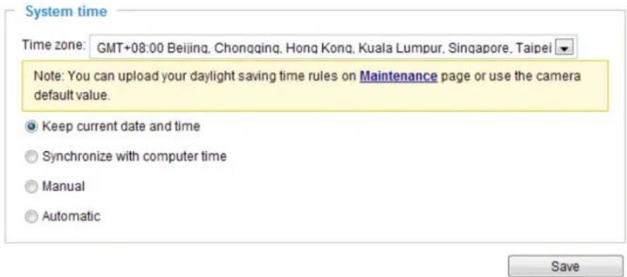
Keep current date and time: Select this option to preserve the current date and time of the Network Camera. The Network Camera's internal real-time clock maintains the date and time even when the power of the system is turned off.
Synchronize with computer time: Select this option to synchronize the date and time of the Network Camera with the local computer. The read-only date and time of the PC is displayed as updated.
Manual: The administrator can enter the date and time manually. Note that the date and time format are [yyyy/mm/dd] and [hh:mm:ss].
Automatic: The Network Time Protocol is a protocol which synchronizes computer clocks by periodically querying an NTP Server.
NTP server: Assign the IP address or domain name of the time-server. Leaving the text box blank connects the Network Camera to the default time servers.
Update interval: Select to update the time using the NTP server on an hourly, daily, weekly, or monthly basis.
Time zone Advanced Mode: Select the appropriate time zone from the list. If you want to upload Daylight Savings Time rules, please refer to System > Maintenance > Import/ Export files on page 41 for details.
System > Homepage layout Advanced Mode
This section explains how to set up your own customized homepage layout.
General settings
This column shows the settings of your homage layout. You can manually select the background and font colors in Theme Options (the second tab on this page). The settings will be displayed automatically in this Preview field. The following shows the homepage using the default settings:
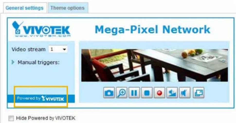
■ Hide Powered by VIVOTEK: If you check this item, it will be removed from the homepage.
Logo graph
Here you can change the logo at the top of your homepage.
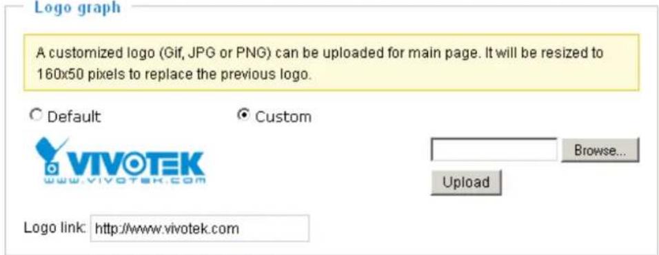
Follow the steps below to upload a new logo:
- Click Custom and the Browse field will appear.
- Select a logo from your files.
- Click Upload to replace the existing logo with a new one.
- Enter a website link if necessary.
- Click Save to enable the settings.
Customized button
If you want to hide manual trigger buttons on the homepage, please uncheck this item. This item is checked by default. Customized button

Theme Options
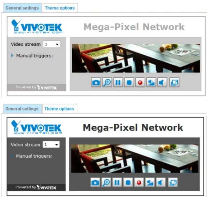
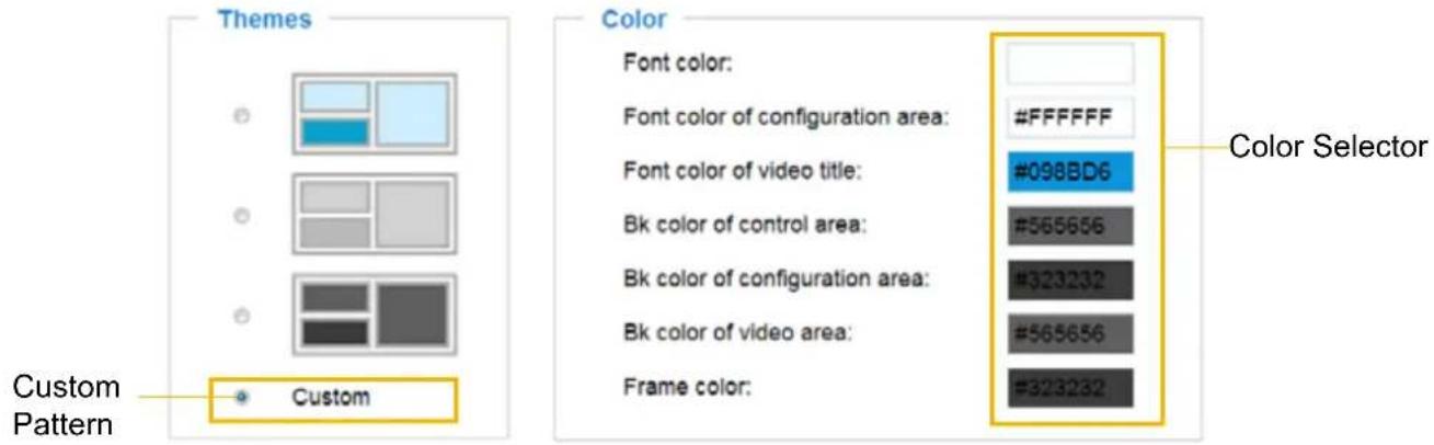
Here you can change the color of your homepage layout. There are three types of preset patterns for you to choose from. The new layout will simultaneously appear in the Preview filed. Click Save to enable the settings.
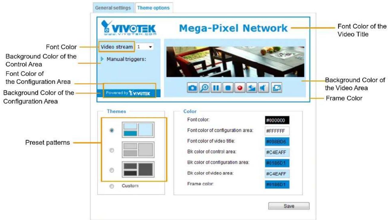
■ Follow the steps below to set up the customed homepage:
- Click Custom on the left column.
- Click the field where you want to change the color on the right column.
- The palette window will pop up as shown below.
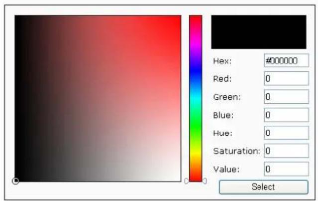
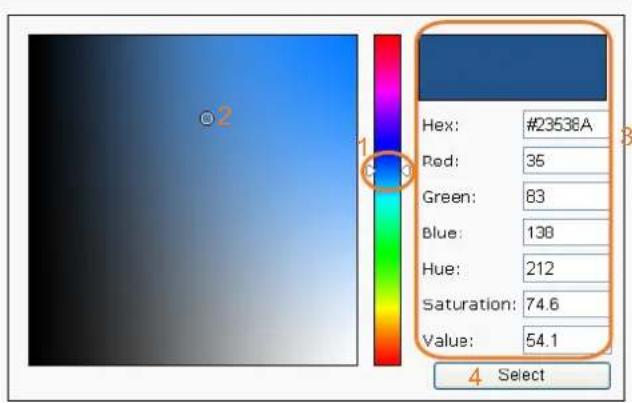
- Drag the slider bar and click on a spot on the left square to select a desired color.
- The selected color will be displayed in the corresponding fields and in the Preview column.
- Click Save to enable the settings.
System > Logs Advanced Mode
This section explains how to configure the Network Camera to send the system log to a remote server as backup.
Log server settings
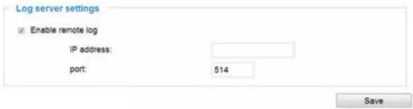
Follow the steps below to set up the remote log:
- Select Enable remote log.
- In the IP address text box, enter the IP address of the remote server.
- In the port text box, enter the port number of the remote server.
- When completed, click Save to enable the setting.
You can configure the Network Camera to send the system log file to a remote server as a log backup. Before utilizing this feature, it is suggested that the user install a log-recording tool to receive system log messages from the Network Camera. An example is Kiwi Syslog Daemon. Visit http://www.kiwisyslog.com/kiwi-syslog-daemon-overview/.
![Kewi Syslog Daemon (Version 7.1.4) File View Help Display 00 [Default] Date Time Priority Hostname Message 01-12-2008 15:21:32 Users.Info 192.168.5.121 [RTSP SERVER] Stop one session, IP=192.168.5.122 01-12-2008 15:21:31 Users.info 192.168.5.121 [RTSP SERVER] Start one session, IP=192.168.5.122 01-12-2008 15:20:47 Syslog.Info 192.168.5.121 syslogd 1.4.1: restart. 100% 3 MPH 15:34 01-12-2008](/content/2026/06/1186415/images/cb81691b815c3ea5236ef409d78eb863e8168004c7ae4a306e5030273bdf332d.jpg)
System log
![Jan 5 11:36.07 syslogd 1.5.0: restart. Jan 5 11:36.08 [swatchdog]: Ready to watch httpd. Jan 5 11:36.09 [EVENT MGR]: Starting eventmgr with support for EcTun Jan 5 11:36:11 [DRM Service]: Starting DRM service. Jan 5 11:36:20 [UPnPIGDCP]: Search IGD failed Jan 5 11:36:23 automount[718]: >> mount: mounting /dev/mmcblk0p1 on /mnt/auto/CF failed: No such device or address Jan 5 11:36:23 automount[718]: mount generic): failed to mount /dev/mmcblk0p1 (type vfat) on /mnt/auto/CF Jan 5 11:36:23 [IR Cut Control]: Day mode Jan 5 11:36:23 automount[728]: >> mount: mounting /dev/mmcblk0p1 on /mnt/auto/CF failed: No such device or address Jan 5 11:36:23 automount[728]: mount generic): failed to mount /dev/mmcblk0p1 (type vfat) on /mnt/auto/CF Jan 5 11:36:23 [IR Cut Control]: Day mode Jan 5 11:36:23 [SYS]: Serial number = 0002D10ED4C9 Jan 5 11:36:23 [SYS]: System starts at Wed Jan 5 11:36:23 UTC 2011](/content/2026/06/1186415/images/0195b58e4e8e2cbc6b7bee0ada0521e078a7f8bac11d544653e35cc9e8da4929.jpg)
This column displays the system log in a chronological order. The system log is stored in the Network Camera's buffer area and will be overwritten when reaching a certain limit.
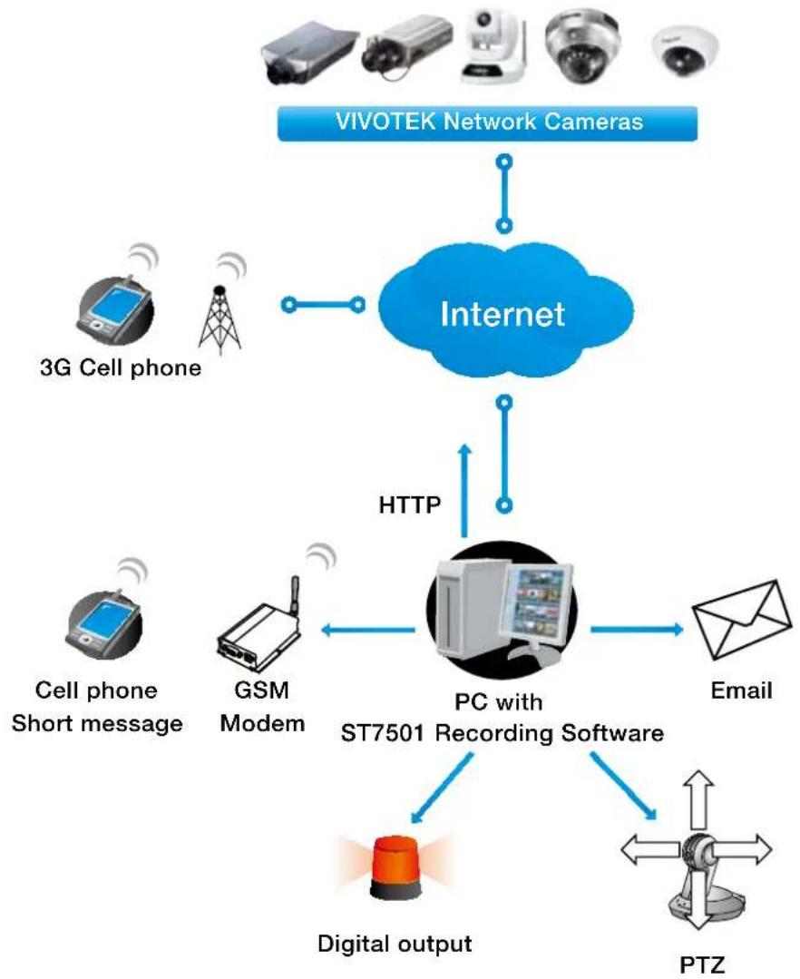
You can install the included ST7501 recording software, which provides an Event Management function group for delivering event messages via emails, GSM short messages, onscreen event panel, or to trigger an alarm, etc. For more information, refer to the ST7501 User Manual.
flowchart
graph TD
    A["VIVOTEK Network Cameras"] --> B["Internet"]
    B --> C["3G Cell phone"]
    B --> D["3G Cell phone Short message"]
    B --> E["GSM Modem"]
    B --> F["PC with ST7501 Recording Software"]
    B --> G["Digital output"]
    B --> H["PTZ"]
    B --> I["Email"]
    B --> J["HTTP"]
    J --> B
Access log
System log Access log
Jan 5 11:36:28 [RTSP SERVER]: Start one session, IP=172.16.2.52
Jan 5 11:49:15 [RTSP SERVER]: Start one session, IP=192.168.4.105
Jan 5 13:11:20 [RTSP SERVER]: Start one session, IP=192.168.4.105
Access log displays the access time and IP address of all viewers (including operators and administrators) in a chronological order. The access log is stored in the Network Camera's buffer area and will be overwritten when reaching a certain limit.
System > Parameters Advanced Mode
The View Parameters page lists the entire system's parameters. If you need technical assistance, please provide the information listed on this page.
Parameters
system_hostname='Mega-Pixel Network Camera'
system_ledoff='0'
system_lowlight='1'
system_date='2013/03/11'
system_time='18:02:41'
system_datetime�'
system_ntp='
system_timezone
system_timezone
system Complaintindex='320'
system daylight_enable='0'
system daylight_dstactualmode='1'
system daylight_auto_begintime='NONE'
system daylight_auto_endtime='NONE'
system daylight_timezones=',-360,-320,-280,-240,-241,-200,-201,-160,-14
system_updateinterval='86400'
system_info_modelname='FD8166'
system_info_extendedmodelname='FD8166'
system_info_serialnumber='00D281660007'
system_info_firmwareversion='FD8166-VVTK-0100c'
system_info_language_count='9'
system_info_language_i0='English'
system_info_language_i1='Deutsch'
system_info_language_i2='Español'
system_info_language_i3='Français'
system_info_language_i4='Italiano'
system_info_language_i5='日本語'
system_info_language_i6='Português'
system_info_language_i7='简体中文'
system_info_language_i8='繁體中文'
System > Maintenance
This chapter explains how to restore the Network Camera to factory default, upgrade firmware version, etc.
General settings > Upgrade firmware
Upgrade firmware
Select firmware file:
Browse.
Upgrade
This feature allows you to upgrade the firmware of your Network Camera. It takes a few minutes to complete the process.
Note: Do not power off the Network Camera during the upgrade!
Follow the steps below to upgrade the firmware:
- Download the latest firmware file from the VIVOTEK website. The file is in .pkg file format.
- Click Browse... and specify the firmware file.
- Click Upgrade. The Network Camera starts to upgrade and will reboot automatically when the upgrade completes.
If the upgrade is successful, you will see "Reboot system now!! This connection will close". After that, re-access the Network Camera.
The following message is displayed when the upgrade has succeeded.
Reboot system now!! This connection will close.
The following message is displayed when you have selected an incorrect firmware file.
Starting firmware upgrade...
Do not power down the server during the upgrade.
The server will restart automatically after the upgrade is completed.
This will take about 1 - 5 minutes.
Wrong PKG file format
Unpack fail
General settings > Reboot
Reboot
Reboot
This feature allows you to reboot the Network Camera, which takes about one minute to complete. When completed, the live video page will be displayed in your browser. The following message will be displayed during the reboot process.
The device is rebooting now. Your browser will reconnect to http://192.168.5.151:80/ If the connection fails, please manually enter the above IP address in your browser.
[Non-Text]
If the connection fails after rebooting, manually enter the IP address of the Network Camera in the address field to resume the connection.
General settings > Restore
Restore
Restore all settings to factory default except settings in

Network

Daylight saving time

Custom language
Restore
This feature allows you to restore the Network Camera to factory default settings.
Network: Select this option to retain the Network Type settings (please refer to Network Type on page 56).
Daylight Saving Time: Select this option to retain the Daylight Saving Time settings (please refer to Import/Export files below on this page).
Custom Language: Select this option to retain the Custom Language settings.
If none of the options is selected, all settings will be restored to factory default. The following message is displayed during the restoring process.
The device is rebooting now. Your browser will reconnect to http://192.168.5.151:80/ If the connection fails, please manually enter the above IP address in your browser.

Import/Export files
Advanced Mode
This feature allows you to Export / Update daylight saving time rules, custom language file, configuration file, and server status report.
General settings
Import/Export files
Export files
Export daylight saving time configuration file
Export
Export language file
Export
Export configuration file
Export
Export server status report
Export
Upload files
Update daylight saving time rules:
Browse...
Upload
Update custom language file:
Browse...
Upload
Upload configuration file:
Browse..
Upload
Export daylight saving time configuration file: Click to set the start and end time of DST (Daylight Saving).
Follow the steps below to export:
-
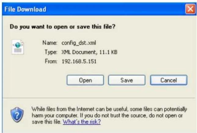
In the Export files column, click Export to export the daylight saving time configuration file from the Network Camera.
-
A file download dialog will pop up as shown below. Click Open to review the XML file or click Save to store the file for editing.
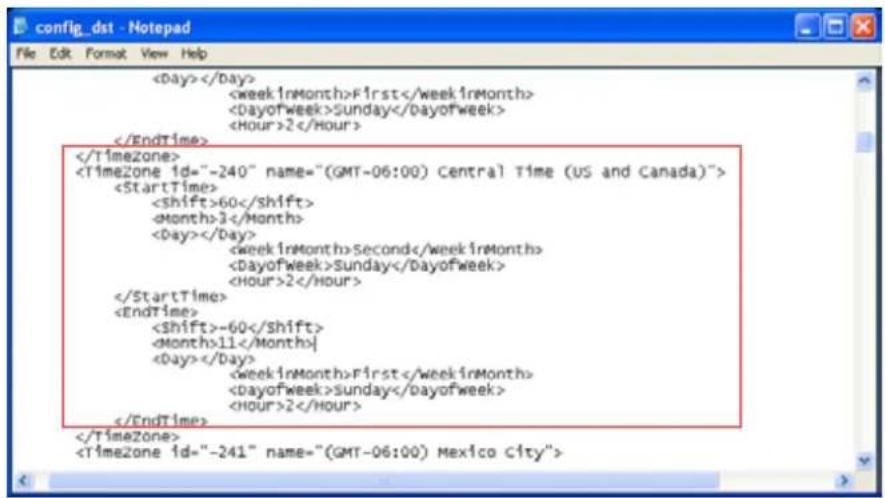
- Open the file with Microsoft ^® Notepad and locate your time zone; set the start and end time of DST. When completed, save the file.
In the example below, DST begins each year at 2:00 a.m. on the second Sunday in March and ends at 2:00 a.m. on the first Sunday in November.
Update daylight saving time rules: Click Browse... and specify the XML file to update.
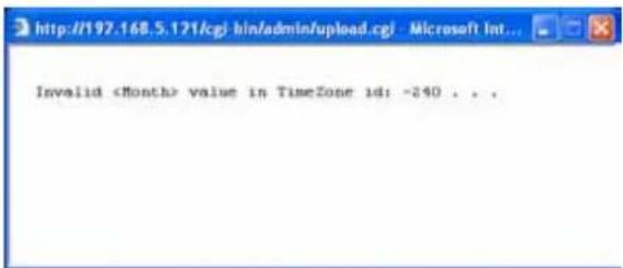
If the incorrect date and time are assigned, you will see the following warning message when uploading the file to the Network Camera.
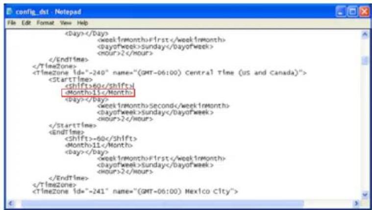
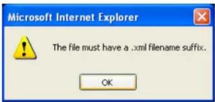
The following message is displayed when attempting to upload an incorrect file format.
Export language file: Click to export language strings. VIVOTEK provides nine languages: English, Deutsch, Español, Français, Italiano, 日本語, Português, 簡体中文, and 繁體中文.
Update custom language file: Click Browse... and specify your own custom language file to upload.
Export configuration file: Click to export all parameters for the device and user-defined scripts.
Update configuration file: Click Browse... to update a configuration file. Please note that the model and firmware version of the device should be the same as the configuration file. If you have set up a fixed IP or other special settings for your device, it is not suggested to update a configuration file.
Export server staus report: Click to export the current server status report, such as time, logs, parameters, process status, memory status, file system status, network status, kernel message ... and so on.
Media > Image
Advanced Mode
This section explains how to configure the image settings of the Network Camera. It is composed of the following four columns: General settings, Picture settings, Exposure, and Privacy mask.
General settings
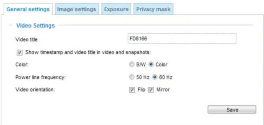
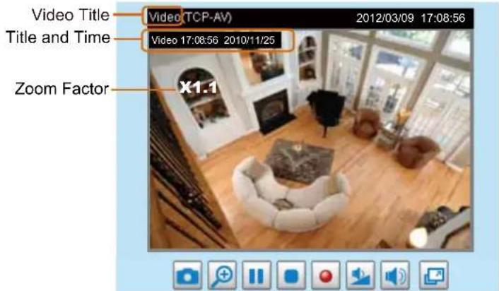
Video title: Enter a name that will be displayed on the title bar of the live video as the picture shown below.
Show timestamp and video title in videos and snapshots: Select this checkbox if you prefer video title and time stamp to display in videos and snapshots.
A zoom indicator will be displayed on the Home page when you zoom in/out the live viewing window as the picture shown below. You may zoom in/out the image by scrolling the mouse wheel inside the live viewing window, and the maximum zoom in will be up to 4 times.
Color: Select to display color or black/white video streams.
Power line frequency: Set the power line frequency consistent with local utility settings to eliminate image flickering associated with fluorescent lights. Note that after the power line frequency is changed, you must disconnect and reconnect the power cord of the Network Camera in order for the new setting to take effect.
Video orientation: Flip--vertically reflect the display of the live video; Mirror--horizontally reflect the display of the live video. Select both options if the Network Camera is installed upside-down (e.g., on the ceiling) to correct the image orientation. Please note that if you have configured preset locations, those locations will be cleared after flip/mirror setting.
Image settings
On this page, you can tune the White balance, Image adjustment, and low light compensation.
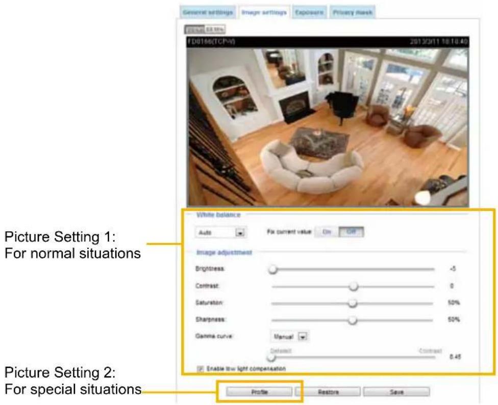
White balance: Adjust the value for the best color temperature.
■ You may follow the steps below to adjust the white balance to the best color temperature.
- Place a sheet of paper of white or cooler-color temperature paper, such as blue, in front of the lens, then allow the Network Camera to automatically adjust the color temperature.
- Click the On button to Fix current value and confirm the setting while the white balance is being measured.
Image Adjustment
■ Brightness: Adjust the image brightness level, which ranges from -5 to +5.
■ Contrast: Adjust the image contrast level, which ranges from -5 to +5.
■ Saturation: Adjust the image saturation level, which ranges from 0 to 100%.
■ Sharpness: Adjust the image sharpness level, which ranges from 0 to 100%. You can also select Customize and manually enter a value.
■ Gamma curve: Adjust the image sharpness level, which ranges from 0.45 to 1.0. You may let firmware Optimize your display or select a value to change the preferred level of Gamma correction towards higher contrast or towards the higher luminance for detailed expression for both dark and lighted areas of an image.
■ Enable low light compensation: Select this option in low light mode, and the values of sharpness and brightness will change automatically as the firmware exerts an automated noise reduction. In low light mode, system will increase input gains, and as a side effect, noises will also increase. This function reduces the noises in images taken in low light scenarios.
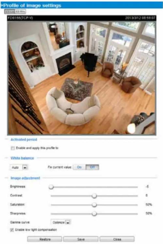
You can click Restore to recall the original settings without incorporating the changes. When completed with the settings on this page, click Save to enable the setting. You can also click on Profile to adjust all settings above in a pop-up window for special lighting conditions for during a specific period of time in a day.
Activated period: Select the period of time this profile setting will apply to. Please manually enter a range of time in a day, tune the White Balance and Image adjustment settings as previously described, and then check Save for the configuration to take effect.
Exposure Advanced Mode
On this page, you can set the Measurement window, Exposure level, Exposure time, and Gain control settings. Detailed configurations will be automatically adjusted since the sensor library will automatically adjust the value according to the ambient light.
Sensor Setting 1: For normal situations
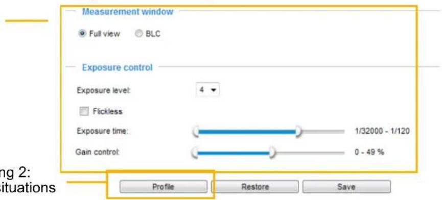
Sensor Setting 2: For special situations
Measurement Window: This function allows user to set measurement window(s) for low light compensation.
■ Full view: Calculate the full range of view and offer appropriate light compensation.
■ BLC (Back Light Compensation): This option allows you to use the center of the current view as the measuring area. The measuring window refers to "weighted window" where the lighting condition within the particular area is taken into account. Camera firmware then adopts the weighted averages method to calculate the value and provides necessary light compensation.
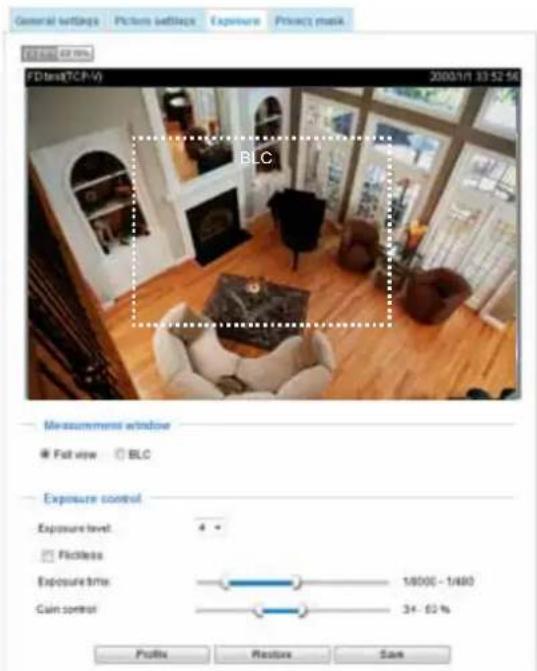
Exposure control:
■ Exposure level: You can manually set the Exposure level, which ranges from 0 to 8 (dark to bright).
■ Flickerless: This function helps avoid the flickering on images because of the fast shutter movement and the inconsistency between power line frequency and exposure time. When selected, the exposure time will be forced to stay longer than 1/120 second. For cameras that come with fixed iris lens, setting the exposure time to longer than 1/120 second may introduce too much lights to the lens. Users can use this option to observe whether the result of long exposure time is satisfactory.
■ Exposure time: The Exposure time allows tuning for more or less light to enter the lens. The configurable value ranges from 1/32000 to 1/5 of a second. An optimum shutter speed should be maintained as long as the light level of the scene permits.
■ Gain control: Tune the slider bar to set the Gain Control to the best image quality. Higher gain control value will generate a certain amount of noise, and that the gain control, lighting levels, and picture performance are closely related.
Note that you can split the round pointers on the Exposure time and Gain control slide bars into two halves and drag them on the bars to designate a range of values in which firmware can automatically adapt to. Firmware will then automatically tune the Gain, Exposure time, and Iris opening within the ranges you specified.
You can click Restore to recall the original settings without incorporating the changes. When completed with the settings on this page, click Save to enable the settings.
If you want to configure another sensor setting for the schedule mode, please click Profile to open the Profile of exposure settings page as shown below.
Activated period: Select the period of time this profile setting will apply to. Please manually enter a range of time in a day, fune the Measurement window and Exposure control settings, and then check Save for the configuration to take effect.
Please follow the steps below to setup a profile:
- Check Enable and apply this profile to.
- Enter enter a range of time.
- Configure Exposure control settings in the following columns. Please refer to previous discussions for detailed information.
- Click Save to enable the setting and click Close to exit the page.
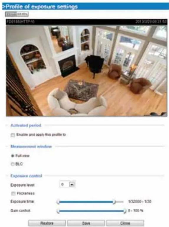
Privacy mask
Advanced Mode
Click Privacy Mask to open the settings page. On this page, you can block out sensitive zones to address privacy concerns.
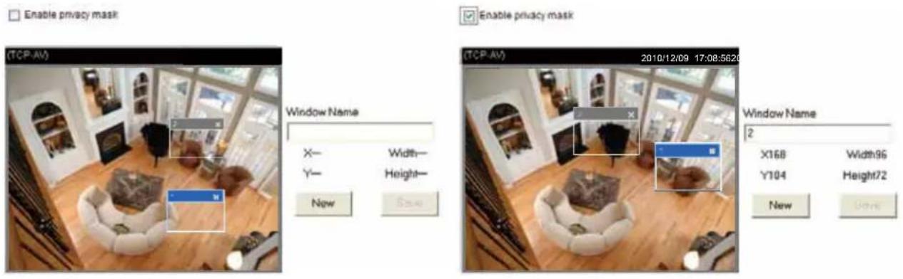
■ To set the privacy mask windows, follow the steps below:
- Click New to add a new window.
- You can use the mouse cursor to size and drag-drop the window, which is recommended to be at least twice the size of the object (height and width) you want to cover.
- Enter a Window Name and click Save to enable the setting.
- Click on the Enable privacy mask checkbox to enable this function.

NOTE:
▶ Up to 5 privacy mask windows can be configured on the same screen.
▶ If you want to delete the privacy mask window, please click the 'x' mark on the upper right corner of the window.
Media > Video
Advanced Mode
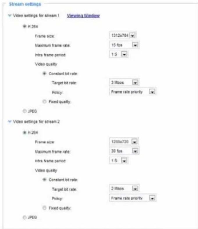
Stream settings
Stream settings
» Video settings for stream 1
Viewing Window
Video settings for stream 2
Save
This Network Camera supports multiple streams with a frame size ranging from 176 x144 to 1920 x 1080.
The definition of multiple streams:
■ Stream 1: Users can define the "Region of Interest" (viewing region) and the "Output Frame Rate" (size of the live view window).
■ Stream 2: Stream 2 does not support the "Region of Interest" configuration.
Click Viewing Window to open the viewing region settings page. On this page, you can set the Region of Interest and the Output Frame Size for stream 1. For example, you can crop only a portion of the image that is of your interest, and thus save the bandwidth needed to transmit the video stream.
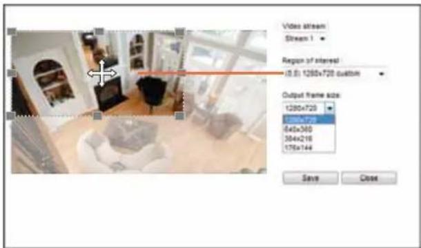
Please follow the steps below to set up those settings for a stream:
- Select a stream for which you want to set up the viewing region.
- Select a Region of Interest from the drop-down list. The floating frame, the same as the one in the Gloabl View window on the home page, will resize accordingly. If you want to set up a customized viewing region, you can also resize and drag the floating frame to a desired position with your mouse.
- Choose a proper Output Frame Size from the drop-down list according to the size of your monitoring device.
Medi: Video NOTE:
▶ All the items in the "Region of Interest" should not be larger than the "Output Frame Size" (current maximum resolution).
■ The parameters of the multiple streams:
| Region of Interest Output frame size | |
| Stream 1 1920 X 1080 ~ 176 x 144 (Selectable) | 1920 X 1080 ~ 176 x 144 (Selectable) |
| Stream 2 fixed fixed |
When completed with the settings in the Viewing Window, click Save to enable the settings and click Close to exit the window. The selected Output Frame Size will immediately be applied to the Frame size of each video stream. Then you can go back to the home page to test the e-PTZ function. For more information about the e-PTZ function, please refer to page 87.
Output Frame Size (Size of the Live View Window)
Click the stream item to display the detailed information. The maximum frame size will follow your settings in the above Viewing Window sections.
This Network Camera offers real-time H.264 and MJPEG compression standards (Dual Codec) for real-time viewing. If the H.264 mode is selected, the video is streamed via RTSP protocol. There are several parameters for you to adjust the video performance:
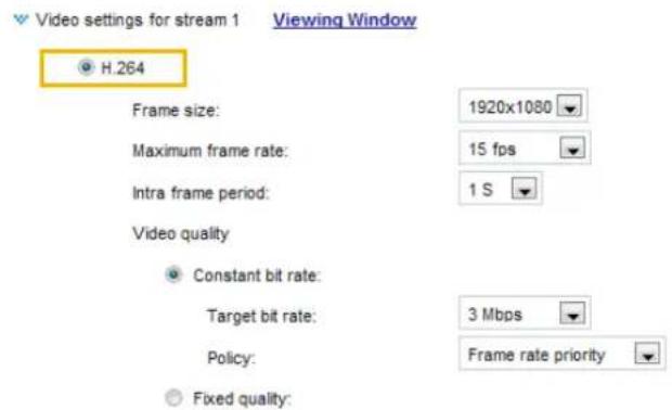
■ Frame size
You can set up different video resolutions for different viewing devices. For example, set a smaller frame size and lower bit rate for remote viewing on mobile phones and a larger video size and a higher bit rate for live viewing on web browsers. Note that a larger frame size takes up more bandwidth.
■ Maximum frame rate
This limits the maximum refresh frame rate per second. Set the frame rate higher for smoother video quality and for recognizing moving objects in the field of view.
If the power line frequency is set to 50Hz, the frame rates are selectable at 1fps, 2fps, 3fps, 5fps, 8fps, 10fps, 15fps, 20fps, and 25fps. If the power line frequency is set to 60Hz, the frame rates are selectable at 1fps, 2fps, 3fps, 5fps, 8fps, 10fps, and 15fps, 20fps, 25fps, and 30fps. You can also select Customize and manually enter a value.
The frame rate will decrease if you select the higher resolution, such 1600x904 and 1920x1080.
■ Intra frame period
Determine how often to plant an I frame. The shorter the duration, the more likely you will get better video quality, but at the cost of higher network bandwidth consumption. Select the intra frame period from the following durations: 1/4 second, 1/2 second, 1 second, 2 seconds, 3 seconds, and 4 seconds.
■ Video quality
Constant bit rate:
- Constant bit rate: A complex scene generally produces a larger file size, meaning that higher bandwidth will be needed for data transmission. The bandwidth utilization is configurable to match a selected level, resulting in mutable video quality performance. The bit rates are selectable at the following rates: 20Kbps, 30Kbps, 40Kbps, 50Kbps, 64Kbps, 128Kbps, 256Kbps, 512Kbps, 768Kbps, 1Mbps, 2Mbps, 3Mbps, 4Mbps, 6Mbps, and 8Mbps. You can also select Customize and manually enter a value. This bit rate restriction method is particularly useful when planning a configuration consisting of numerous cameras where video streams can produce high demands both on network bandwidth and storage space. For example, storing a 6Mbps stream for 24 hours requires a 63GB disk space.
The Network Camera will strive to deliver video streams within the bit rate limitation you impose. If Frame Rate Priority is selected, the Network Camera will try to maintain the frame rate per second performance, while image quality will be compromised. If Image quality priority is preferred, the Network Camera will try to maintain the image quality of each frame, while the frame rate per second will be compromised.
- Fixed quality: On the other hand, if Fixed quality is selected, all frames are transmitted with the same quality; bandwidth utilization is therefore unpredictable. The video quality can be adjusted to the following settings: Medium, Standard, Good, Detailed, and Excellent. You can also select Customize and manually enter a value. The image quality will then be determined by the compression rate. For example, a lower quality means a higher compression rate. The higher the compression rate, the higher the possibility of image distortion, etc. You can also select Customize and manually enter a logical value from 0 to 51.
If JPEG mode is selected, the Network Camera sends consecutive JPEG images to the client, producing a moving effect similar to a filmstrip. Every single JPEG image transmitted guarantees the same image quality, which in turn comes at the expense of variable bandwidth usage. Because the media contents are a combination of JPEG images, no audio data is transmitted to the client. There are three parameters provided in MJPEG mode to control the video performance:
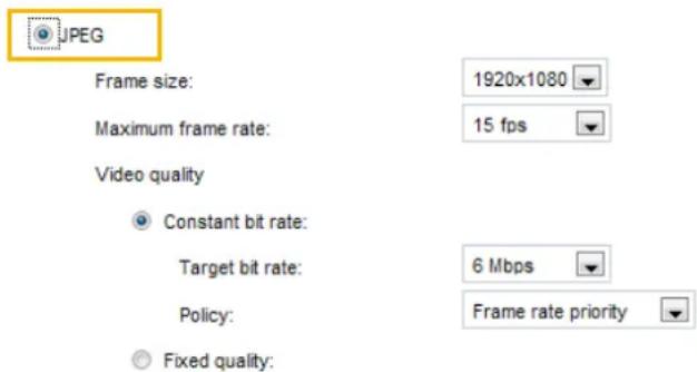
■ Frame size
You can set up different video resolution for different viewing devices. For example, set a smaller frame size and lower bit rate for remote viewing on mobile phones and a larger video size and a higher bit rate for live viewing on web browsers. Note that a larger frame size takes up more bandwidth.
■ Maximum frame rate
This limits the maximum refresh frame rate per second. Set the frame rate higher for smoother video quality.
The frame rate will decrease if you select the higher resolution, such 1600x904 and 1920x1080.
If the power line frequency is set to 50Hz, the frame rates are selectable at 1fps, 2fps, 3fps, 5fps, 8fps, 10fps, 15fps, 20fps, and 25fps. If the power line frequency is set to 60Hz, the frame rates are selectable at 1fps, 2fps, 3fps, 5fps, 8fps, 10fps, 15fps, 20fps, 25fps, and 30fps. You can also select Customize and manually enter a value. The frame rate will decrease if you select a higher resolution.
■ Video quality
Refer to the previous discussion in the H.264 format settings on page 53 for the Constant bit rate and Fixed quality configurations.

NOTE:
▶ If you configure a Customized value for the Fixed Quality setting in Video quality, the value will then represent the compression rate. In here, a lower value will produce higher quality.
▶ Converting high-quality video may significantly increase the CPU loading, and you may encounter streaming disconnection or video loss while capturing a complicated scene. In the event of such occurrence, we suggest you customize a lower video resolution or reduce the frame rate to obtain smooth video.
Media > Audio Advanced Mode
Audio Settings
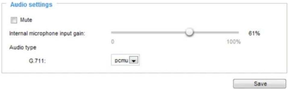
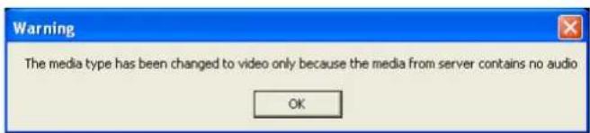
Mute: Select this option to disable audio transmission from the Network Camera to all clients. Note that if muted, no audio data will be transmitted even if audio transmission is enabled on the Client Settings page. In that case, the following message is displayed:
Internal microphone input gain: Select the gain of the external audio input according to ambient conditions by dragging the pointer on the slide bar.
Audio type: Advanced Mode.
■ G.711 provides good sound quality and requires about 64Kbps. Select pcmu ( -Law) or pcma (A-Law) mode.
When completed with the settings on this page, click Save to enable the settings.
Network > General settings
This section explains how to configure a wired network connection for the Network Camera.
Network Type
LAN
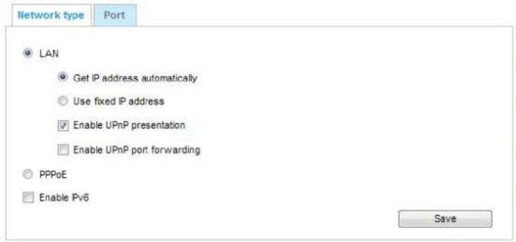
Select this option when the Network Camera is deployed on a local area network (LAN) and is intended to be accessed by local computers. The default setting for the Network Type is LAN. Please remember to click Save when you complete the Network setting.
Get IP address automatically: Select this option to obtain an available dynamic IP address assigned by the DHCP server each time the camera is connected to the LAN.
Use fixed IP address: Select this option to manually assign a static IP address to the Network Camera.
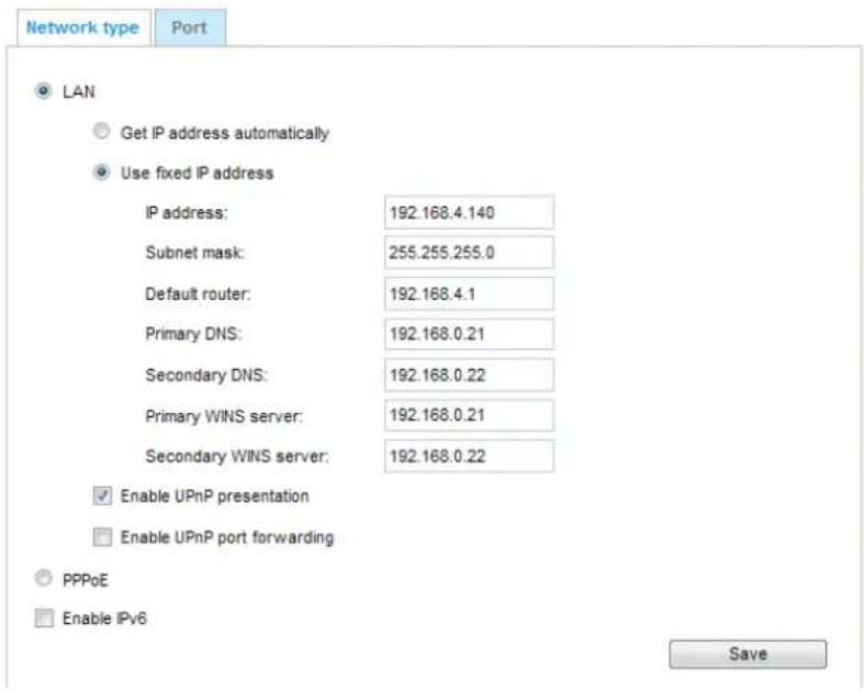
- You can make use of VIVOTEK Installation Wizard 2 on the software CD to easily set up the Network Camera on LAN. Please refer to Software Installation on page 12 for details.
- Enter the Static IP, Subnet mask, Default router, and Primary DNS provided by your ISP or consult your network administrator.
Subnet mask: This is used to determine if the destination is in the same subnet. The default value is "255.255.255.0".
Default router: This is the gateway used to forward frames to destinations in a different subnet. Invalid router setting will fail the transmission to destinations in different subnet.
Primary DNS: The primary domain name server that translates hostnames into IP addresses.
Secondary DNS: Secondary domain name server that backups the Primary DNS.
Primary WINS server: The primary WINS server that maintains the database of computer names and IP addresses.
Secondary WINS server: The secondary WINS server that maintains the database of computer names and IP addresses.
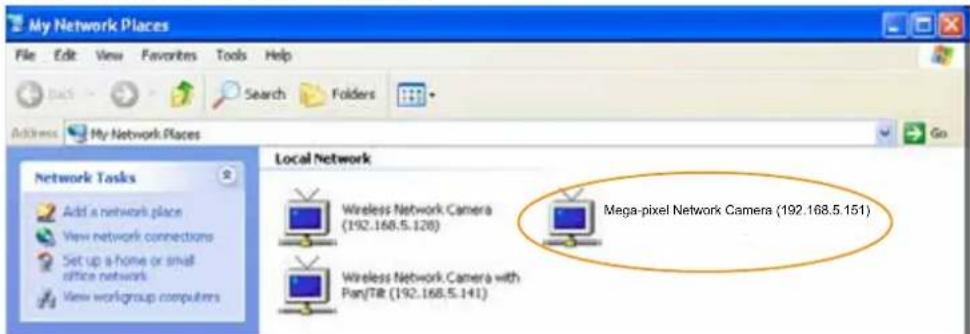
Enable UPnP presentation: Select this option to enable UPnP ^TM presentation for your Network Camera so that whenever a Network Camera is presented to the LAN, shortcuts of connected Network Cameras will be listed in My Network Places. You can click the shortcut to link to the web browser. Currently, UPnP ^TM is supported by Windows XP or later. Note that to utilize this feature, please make sure the UPnP ^TM component is installed on your computer.
Enable UPnP port forwarding: To access the Network Camera from the Internet, select this option to allow the Network Camera to open ports on the router automatically so that video streams can be sent out from a LAN. To utilize of this feature, make sure that your router supports UPnP™ and it is activated.
PPPoE (Point-to-point over Ethernet)
Select this option to configure your Network Camera to make it accessible from anywhere as long as there is an Internet connection. Note that to utilize this feature, it requires an account provided by your ISP.
Follow the steps below to acquire your Network Camera's public IP address.
-
Set up the Network Camera on the LAN.
-
Go to Configuration > Event > Event settings > Add server (please refer to Add server on page 94) to add a new email or FTP server.
-
Go to Configuration > Event > Event settings > Add media (please refer to Add media on page 99). Select System log so that you will receive the system log in TXT file format which contains the Network Camera's public IP address in your email or on the FTP server.
-
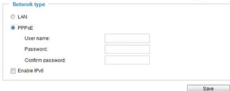
Go to Configuration > Network > General settings > Network type. Select PPPoE and enter the user name and password provided by your ISP. Click Save to enable the setting.
-
The Network Camera will reboot.
-
Disconnect the power to the Network Camera; remove it from the LAN environment.

NOTE:
▶ If the default ports are already used by other devices connected to the same router, the Network Camera will select other ports for the Network Camera.
If UPnP ^TM is not supported by your router, you will see the following message: Error: Router does not support UPnP port forwarding.
▶ Steps to enable the UPnP ^TM user interface on your computer:
Note that you must log on to the computer as a system administrator to install the UPnP ^TM components.
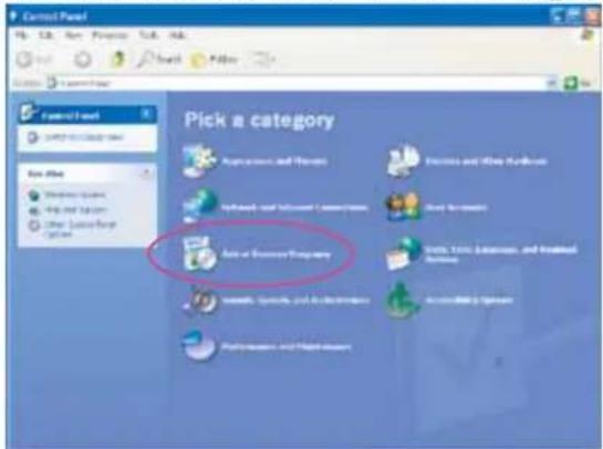
- Go to Start, click Control Panel, then click Add or Remove Programs.
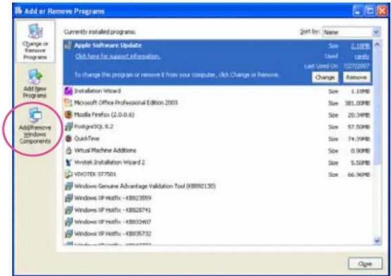
- In the Add or Remove Programs dialog box, click Add/Remove Windows Components.
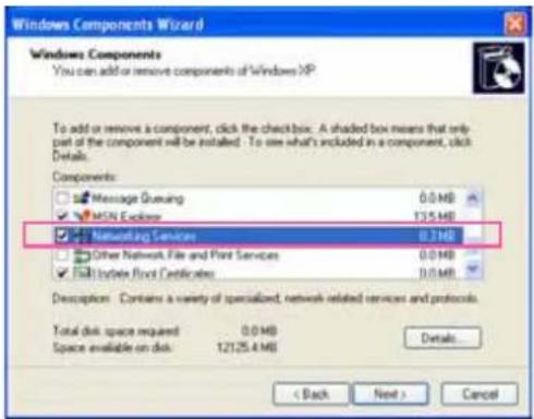
- In the Windows Components Wizard dialog box, select Networking Services and click Details.
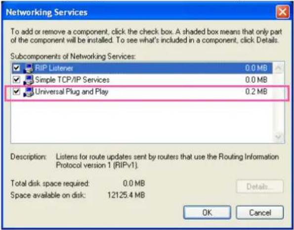
- In the Networking Services dialog box, select Universal Plug and Play and click OK.
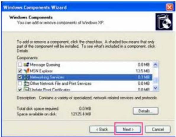
- Click Next in the following window.
- Click Finish. UPnP ^TM is enabled.
▶ How does UPnP ^TM work?
UPnP ^TM networking technology provides automatic IP configuration and dynamic discovery of devices added to a network. Services and capabilities offered by networked devices, such as printing and file sharing, are available among each other without the need for cumbersome network configuration. In the case of Network Cameras, you will see Network Camera shortcuts under My Network Places.
▶ Enabling UPnP port forwarding allows the Network Camera to open a secondary HTTP port on the router-not HTTP port-meaning that you have to add the secondary HTTP port number to the Network Camera's public address in order to access the Network Camera from the Internet. For example, when the HTTP port is set to 80 and the secondary HTTP port is set to 8080, refer to the list below for the Network Camera's IP address.
| From the Internet In LAN | |
| http://203.67.124.123:8080 http://192.168.4.160 or http://192.168.4.160:8080 | |
▶ If the PPPoE settings are incorrectly configured or the Internet access is not working, restore the Network Camera to factory default; please refer to Restore on page 41 for details. After the Network Camera is reset to factory default, it will be accessible on the LAN.
Enable IPv6
Select this option and click Save to enable IPv6 settings.
Please note that this only works if your network environment and hardware equipment support IPv6. The browser should be Microsoft® Internet Explorer 8.x, Mozilla Firefox 12 or above.
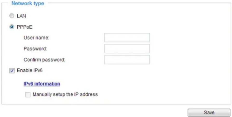
When IPv6 is enabled, by default, the network camera will listen to router advertisements and be assigned with a link-local IPv6 address accordingly.
IPv6 Information: Click this button to obtain the IPv6 information as shown below.
![[eth0 address] fe80:0000:0000:0000:0201:0aff:fe83:6408/64@Li [Gateway] fe80:352d:e315.83a5.4d12 [DNS] IPv6 address list of DNS Close](/content/2026/06/1186415/images/c8ccfe516a253d3ebb48df8a60704b837f776619788bf1671d1539f5c50e2c03.jpg)
If your IPv6 settings are successful, the IPv6 address list will be listed in the pop-up window. The IPv6 address will be displayed as follows:
Refers to Ethernet
![[eth0 address] 2001:0c08:2500:0002:0202:d1ff:fe04:65f4/64@Global fe80:0000:0000:0000:0202:d1ff:fe04:65f4/64@Link [Gateway] fe80:211:d8ff:fea2:1a2b [DNS] 2010:05c0:978d::](/content/2026/06/1186415/images/483c931580ce65e585dbcfb3b2dff9108134861d37b4cdaabcee2e21f0377bb3.jpg)
Please follow the steps below to link to an IPv6 address:
- Open your web browser.
- Enter the link-global or link-local IPv6 address in the address bar of your web browser.
- The format should be:
![http://[2001:0c08:2500:0002:0202:d1ff:fe04:65f4]/ IPv6 address](/content/2026/06/1186415/images/a6571903cdd46840a094d6f436a2b0c5eb7451352be70ec42510710dc687081c.jpg)
- Press Enter on the keyboard or click Refresh button to refresh the webpage. For example:
![Network Camera - Microsoft Internet Explorer File Edit View Favorites Tools Help Back Search Favorites Address http://[2001:0c08:2500:0002:0202:d1ff:fe04:65f4]/ VIVOTEK www.vivotek.com](/content/2026/06/1186415/images/3020c4d66fe435de81191d083ca7507a391b997c853bbde9badc80bc78f4c38e.jpg)

NOTE:
▶ If you have a Secondary HTTP port (the default value is 8080), you can also link to the webpage in the following address format: (Please refer to HTTP streaming on page 63 for detailed information.)
![http://[2001:0c08:2500:0002:0202:d1ff:fe04:65f4]/:8080 IPv6 address Secondary HTTP port](/content/2026/06/1186415/images/2aeb77694f212de4332d79fccdcc8906a29305841f4977b8c1a8d7b8c09b5da1.jpg)
▶If you choose PPPoE as the Network Type, the [PPP0 address] will be displayed in the IPv6 information column as shown below.
![[eth0 address] fe80:0000:0000:0000:0202:d1ff:fe11:2299/64@Link [ppp0 address] fe80:0000:0000:0000:0202:d1ff:fe11:2299/10@Link 2001:b100:01c0:0002:0202:d1ff:fe11:2299/64@Global [Gateway] fe80::90:1a00:4142:8ced [DNS] 2001:b000::1](/content/2026/06/1186415/images/a72db462138daea36bd7dcb31a87a2a3fe2a598e548276bb9ac275d78a539107.jpg)
Manually setup the IP address: Select this option to manually set up IPv6 settings if your network environment does not have DHCPv6 server and router advertisements-enabled routers. If you check this item, the following blanks will be displayed for you to enter the corresponding information:
Enable IPv6
IPv6 information
√ Manually setup the IP address
Optional IP address / Prefix length
Optional default router
Optional primary DNS



Port
Network type
Port
HTTPS port:
443
FTP port:
21
Save
HTTPS port: By default, the HTTPS port is set to 443. It can also be assigned to another port number between 1025 and 65535.
FTP port: The FTP server allows the user to save recorded video clips. You can utilize VIVOTEK's Installation Wizard 2 to upgrade the firmware via FTP server. By default, the FTP port is set to 21. The FTP port can also be assigned to another port number between 1025 and 65535.
Network > Streaming protocols
Advanced Mode
HTTP streaming
To utilize HTTP authentication, make sure that your have set a password for the Network Camera first; please refer to Security > User account on page 73 for details.
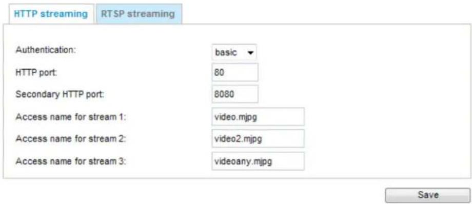
Authentication: Depending on your network security requirements, the Network Camera provides two types of security settings for an HTTP transaction: basic and digest.
If basic authentication is selected, the password is sent in plain text format and there can be potential risks of being intercepted. If digest authentication is selected, user credentials are encrypted using MD5 algorithm and thus provide better protection against unauthorized accesses.
HTTP port / Secondary HTTP port: By default, the HTTP port is set to 80 and the secondary HTTP port is set to 8080. They can also be assigned to another port number between 1025 and 65535. If the ports are incorrectly assigned, the following warning messages will be displayed:
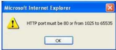
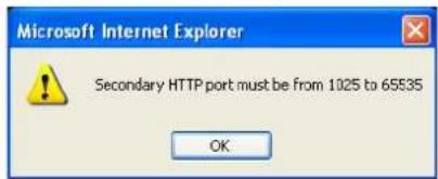
To access the Network Camera on the LAN, both the HTTP port and secondary HTTP port can be used to access the Network Camera. For example, when the HTTP port is set to 80 and the secondary HTTP port is set to 8080, refer to the list below for the Network Camera's IP address.
On the LAN http://192.168.4.160 or http://192.168.4.160:8080
Access name for stream 1, 2, and 3: This Network camera supports multiple streams simultaneously. The access name is used to differentiate the streaming source. Users can click Media -> Video -> Stream settings to set up the video quality of linked streams. For more information about how to set up the video quality, please refer to Stream settings on page 50.
When using Mozilla Firefox to access the Network Camera and the video mode is set to JPEG, users will receive video comprised of continuous JPEG images. This technology, known as “server push”, allows the Network Camera to feed live pictures to Mozilla Firefox.
URL command -- http://
- Launch Mozilla Firefox or Netscape.
- Type the above URL command in the address bar. Press Enter.
- The JPEG images will be displayed in your web browser.
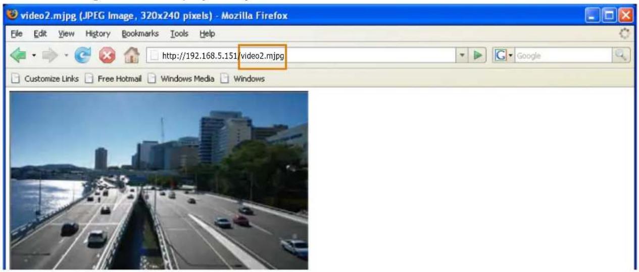

NOTE:
▶ Microsoft® Internet Explorer does not support server push technology; therefore, using the http://
▶ Users can only use URL commands to request the stream 5. For more information about URL commands, please refer to page 117.
RTSP Streaming
To utilize RTSP streaming authentication, make sure that you have set a password for the Network Camera first; please refer to Security > User account on page 73 for details.
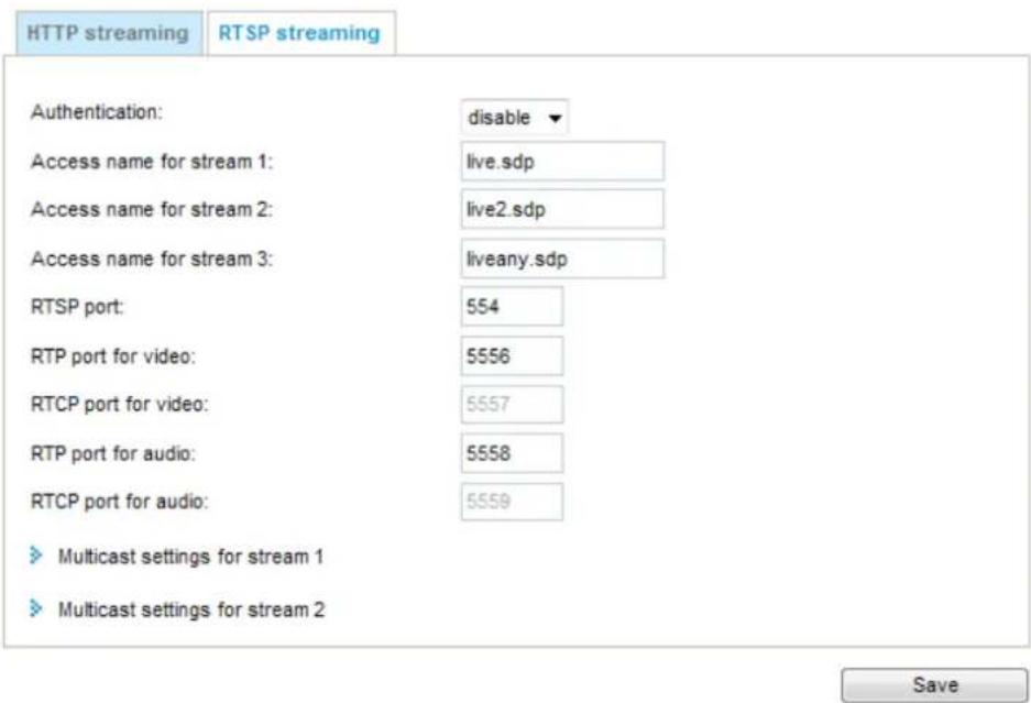
Authentication: Depending on your network security requirements, the Network Camera provides three types of security settings for streaming via RTSP protocol: disable, basic, and digest.
If basic authentication is selected, the password is sent in plain text format, but there can be potential risks of it being intercepted. If digest authentication is selected, user credentials are encrypted using MD5 algorithm, thus providing better protection against unauthorized access.
The availability of the RTSP streaming for the three authentication modes is listed in the following table:
| Quick Time player VLC Player | ||
| Disable O O | ||
| Basic O O | ||
| Digest O X | ||
Access name for stream 1, 2, and 3: This Network camera supports multiple streams simultaneously. The access name is used to differentiate the streaming source.
If you want to use an RTSP player to access the Network Camera, you have to set the video mode to H.264 and use the following RTSP URL command to request transmission of the streaming data.
rtsp://
For example, when the access name for stream 1 is set to live.sdp:
- Launch an RTSP player.
- Choose File > Open URL. A URL dialog box will pop up.
- Type the above URL command in the text box.
- The live video will be displayed in your player as shown below.
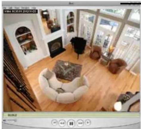
natural_image
Interior view of a modern living room with wooden flooring, framed furniture, and large windows (no visible text or symbols)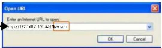
RTSP port /RTP port for video, audio/ RTCP port for video, audio
■ RTSP (Real-Time Streaming Protocol) controls the delivery of streaming media. By default, the port number is set to 554.
■ The RTP (Real-time Transport Protocol) is used to deliver video and audio data to the clients. By default, the RTP port for video is set to 5556 and the RTP port for audio is set to 5558.
■ The RTCP (Real-time Transport Control Protocol) allows the Network Camera to transmit the data by monitoring the Internet traffic volume. By default, the RTCP port for video is set to 5557 and the RTCP port for audio is set to 5559.
The ports can be changed to values between 1025 and 65535. The RTP port must be an even number and the RTCP port is the RTP port number plus one, and thus is always an odd number. When the RTP port changes, the RTCP port will change accordingly.
If the RTP ports are incorrectly assigned, the following warning message will be displayed:
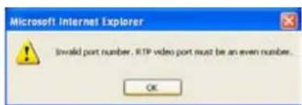
Multicast settings for stream 1 & 2: Click the items to display the detailed configuration information. Select the Always multicast option to enable multicast for stream 1 or 2.
![Multicast settings for stream 1: □ Always multicast Multicast group address: 239.128.1.99 Multicast video port: 5560 Multicast RTCP video port: 5561 Multicast audio port: 5562 Multicast RTCP audio port: 5563 Multicast TTL [1~255]: 15 Multicast settings for stream 2: □ Always multicast Multicast group address: 239.128.1.100 Multicast video port: 5564 Multicast RTCP video port: 5565 Multicast audio port: 5566 Multicast RTCP audio port: 5567 Multicast TTL [1~255]: 15](/content/2026/06/1186415/images/13b317e0a11ac803bca87f320c1056300f29987b120d6795b10fede1fccf3c89.jpg)
Unicast video transmission delivers a stream through point-to-point transmission; multicast, on the other hand, sends a stream to the multicast group address and allows multiple clients to acquire the stream at the same time by requesting a copy from the multicast group address. Therefore, enabling multicast can effectively save Internet bandwidth.
The ports can be changed to values between 1025 and 65535. The multicast RTP port must be an even number and the multicast RTCP port number is the multicast RTP port number plus one, and thus is always odd. When the multicast RTP port changes, the multicast RTCP port will change accordingly.
If the multicast RTP video ports are incorrectly assigned, the following warning message will be displayed:
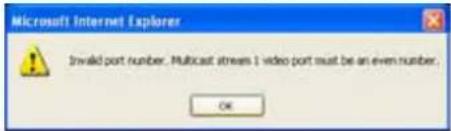
Multicast TTL [1\~255]: The multicast TTL (Time To Live) is the value that tells the router the range a packet can be forwarded.
| Initial TTL Scope | |
| 0 Restricted to the same host | |
| 1 Restricted to the same subnetwork | |
| 32 Restricted to the same site | |
| 64 Restricted to the same region | |
| 128 Restricted to the same continent | |
| 255 Unrestricted in scope | |
Network > DDNS
This section explains how to configure the dynamic domain name service for the Network Camera. DDNS is a service that allows your Network Camera, especially when assigned with a dynamic IP address, to have a fixed host and domain name.
Express link
Express Link is a free service provided by VIVOTEK server, which allows users to register a domain name for a network device. One URL can only be mapped to one MAC address. This service will check out if the host name is valid and automatically open a port on your router. Unlike DDNS, the user has to manually check out UPnP port forwarding, Express Link is more convenient and easy to set up.
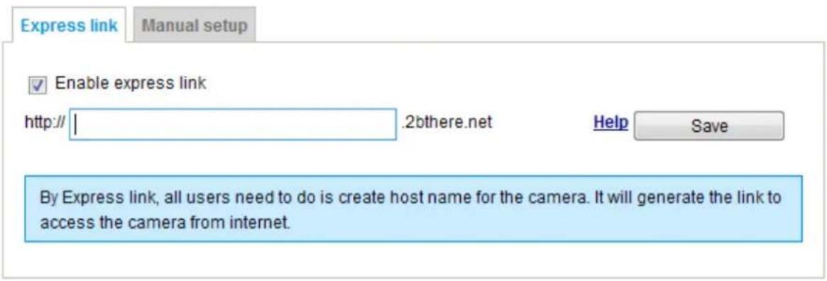
Please follow the steps below to enable Express Link:
- Make sure that your router supports UPnP port forwarding and it is activated.
- Check Enable express link.
- Enter a host name for the network device and click Save. If the host name has been used by another device, a warning message will show up. If the host name is valid, it will show a message as shown below.
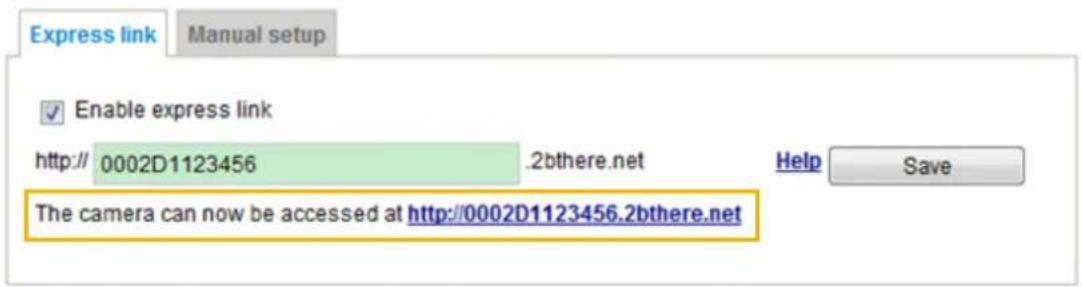
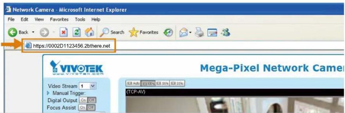
Manual setup
DDNS: Dynamic domain name service
DDNS: Dynamic domain name service
Enable DDNS:
Provider:
Host name:
User name:
Password:
Dyndns.org(Dynamic)
Enable DDNS: Select this option to enable the DDNS setting.
Provider: Select a DDNS provider from the provider drop-down list.
VIVOTEK offers Safe100.net, a free dynamic domain name service, to VIVOTEK customers. It is recommended that you register Safe100.net to access VIVOTEK's Network Cameras from the Internet. Additionally, we offer other DDNS providers, such as Dyndns.org(Dynamic), Dyndns.org(Custom), TZO.com, DHS.org, CustomSafe100, dyn-interfree.it.
Note that before utilizing this function, please apply for a dynamic domain account first.
■ Safe100.net
- In the DDNS column, select Safe100.net from the drop-down list. Click I accept after reviewing the terms of the Service Agreement.
- In the Register column, fill in the Host name (xxxx.safe100.net), Email, Key, and Confirm Key, and click Register. After a host name has been successfully created, a success message will be displayed in the DDNS Registration Result column.
Register
Host name:
Email:
Key:
Confirm key:
WTK.safe100.net
wtk@vivotek.com
...
...
Forget key
To apply for a domain name for the camera, or to modify the previously registered information, fill in the following fields and then click "Register".
Register
DDNS Registration Result:
[Register] Successfully Your account information has been mailed to registered e-mail address
Upon successful registration, you can click copy to automatically upload relevant information to the DDNS form or you can manually fill it in. Then, click "Save" to save new settings.
- Click Copy and all the registered information will automatically be uploaded to the corresponding fields in the DDNS column at the top of the page as seen in the picture.
DDNS: Dynamic domain name service
![Enable DDNS: Provider: Safe100.net Host name: VVTK.safe100.net Email: wtk@vivotek.com Key: ••••• [*.safe100.net]](/content/2026/06/1186415/images/c3f782524f317ee83a689d952c3455d125ffc2bb6bfe4cc0eb46ad676fa51dc0.jpg)
Save
Register
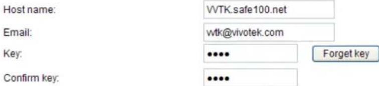
To apply for a domain name for the camera, or to modify the previously registered information, fill in the following fields and then click "Register".
Register
DDNS Registration Result:
[Register] Successfully Your account information has been mailed to registered e-mail address

Upon successful registration, you can click copy to automatically upload relevant information to the DDNS form or you can manually fill it in. Then, click "Save" to save new settings.
- Select Enable DDNS and click Save to enable the setting.
■ CustomSafe100
VIVOTEK offers documents to establish a CustomSafe100 DDNS server for distributors and system integrators. You can use CustomSafe100 to register a dynamic domain name if your distributor or system integrators offer such services.
- In the DDNS column, select CustomSafe100 from the drop-down list.
- In the Register column, fill in the Host name, Email, Key, and Confirm Key; then click Register. After a host name has been successfully created, you will see a success message in the DDNS Registration Result column.
- Click Copy and all for the registered information will be uploaded to the corresponding fields in the DDNS column.
- Select Enable DDNS and click Save to enable the setting.
Forget key: Click this button if you have forgotten the key to Safe100.net or CustomSafe100. Your account information will be sent to your email address.
Refer to the following links to apply for a dynamic domain account when selecting other DDNS providers:
■ Dyndns.org(Dynamic) / Dyndns.org(Custom): visit http://www.dyndns.com/
■ dyn-interfree.it: visit http://dyn-interfree.it/
Network > QoS (Quality of Service) Advanced Mode
Quality of Service refers to a resource reservation control mechanism, which guarantees a certain quality to different services on the network. Quality of service guarantees are important if the network capacity is insufficient, especially for real-time streaming multimedia applications. Quality can be defined as, for instance, a maintained level of bit rate, low latency, no packet dropping, etc.
The following are the main benefits of a QoS-aware network:
■ The ability to prioritize traffic and guarantee a certain level of performance to the data flow.
■ The ability to control the amount of bandwidth each application may use, and thus provide higher reliability and stability on the network.
Requirements for QoS
To utilize QoS in a network environment, the following requirements must be met:
■ All network switches and routers in the network must include support for QoS.
■ The network video devices used in the network must be QoS-enabled.
QoS models
CoS (the VLAN 802.1p model)
IEEE802.1p defines a QoS model at OSI Layer 2 (Data Link Layer), which is called CoS, Class of Service. It adds a 3-bit value to the VLAN MAC header, which indicates the frame priority level from 0 (lowest) to 7 (highest). The priority is set up on the network switches, which then use different queuing disciplines to forward the packets.
Below is the setting column for CoS. Enter the VLAN ID of your switch (0\~4095) and choose the priority for each application (0\~7).
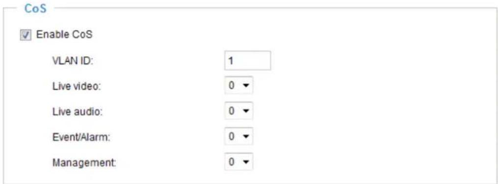
If you assign Video the highest level, the switch will handle video packets first.

NOTE:
▶ A VLAN Switch (802.1p) is required. The web browsing may fail if the CoS setting is incorrect.
▶ Class of Service technologies do not guarantee a level of service in terms of bandwidth and delivery time; they offer a "best-effort." Users can think of CoS as "coarsely-grained" traffic control and QoS as "finely-grained" traffic control.
▶ Although CoS is simple to manage, it lacks scalability and does not offer end-to-end guarantees since it is based on L2 protocol.
QoS/DSCP (the DiffServ model)
DSCP-ECN defines QoS at Layer 3 (Network Layer). The Differentiated Services (DiffServ) model is based on packet marking and router queuing disciplines. The marking is done by adding a field to the IP header, called the DSCP (Differentiated Services Codepoint). This is a 6-bit field that provides 64 different class IDs. It gives an indication of how a given packet is to be forwarded, known as the Per Hop Behavior (PHB). The PHB describes a particular service level in terms of bandwidth, queueing theory, and dropping (discarding the packet) decisions. Routers at each network node classify packets according to their DSCP value and give them a particular forwarding treatment; for example, how much bandwidth to reserve for it.
Below are the setting options of DSCP (DiffServ Codepoint). Specify the DSCP value for each application (0\~63).
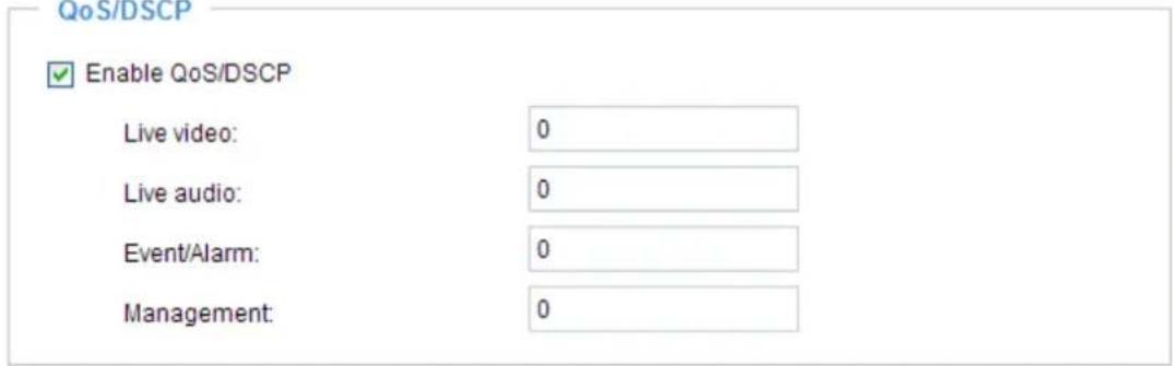
Save
Network > SNMP (Simple Network Management Protocol)
Advanced Mode
This section explains how to use the SNMP on the network camera. The Simple Network Management Protocol is an application layer protocol that facilitates the exchange of management information between network devices. It helps network administrators to remotely manage network devices and find, solve network problems with ease.
■ The SNMP consists of the following three key components:
- Manager: Network-management station (NMS), a server which executes applications that monitor and control managed devices.
- Agent: A network-management software module on a managed device which transfers the status of managed devices to the NMS.
- Managed device: A network node on a managed network. For example: routers, switches, bridges, hubs, computer hosts, printers, IP telephones, network cameras, web server, and database.
Before configuring SNMP settings on the this page, please enable your NMS first.
SNMP Configuration
Enable SNMPv1, SNMPv2c
Select this option and enter the names of Read/Write community and Read Only community according to your NMS settings.
Enable SNMPv1, SNMPv2c

Enable SNMPv3
This option contains cryptographic security, a higher security level, which allows you to set the Authentication password and the Encryption password.
■ Security name: According to your NMS settings, choose Read/Write or Read Only and enter the community name.
■ Authentication type: Select MD5 or SHA as the authentication method.
■ Authentication password: Enter the password for authentication (at least 8 characters).
■ Encryption password: Enter a password for encryption (at least 8 characters).
Enable SNMPv3
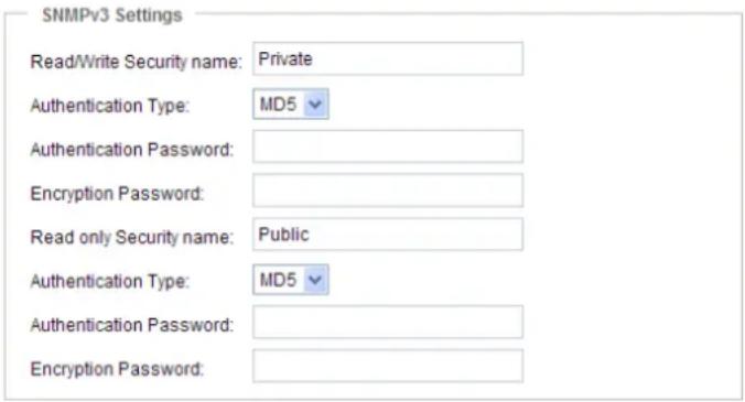
Security > User Account
This section explains how to enable password protection and create multiple accounts.
Root Password

The administrator account name is "root", which is permanent and can not be deleted. If you want to add more accounts in the Manage User column, please apply the password for the "root" account first.
- Type the password identically in both text boxes, then click Save to enable password protection.
- A window will be prompted for authentication; type the correct user's name and password in their respective fields to access the Network Camera.
Privilege Management
Advanced Mode
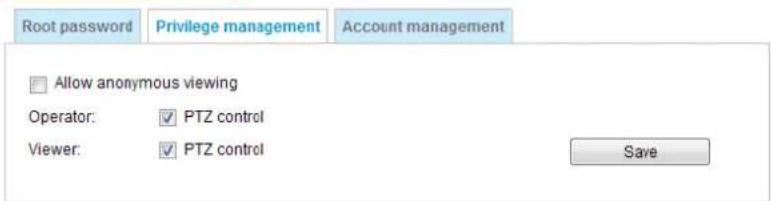
PTZ control: You can modify the management privilege of operators or viewers. Check or uncheck the item, then click Save to enable the settings. If you give Viewers the privilege, Operators will also have the ability to control the Network Camera through the main page. (Please refer to user privilege Configuration on page 73).
Allow anonymous viewing: If you check this item, any client can access the live stream without entering a User ID and Password.
Account Management
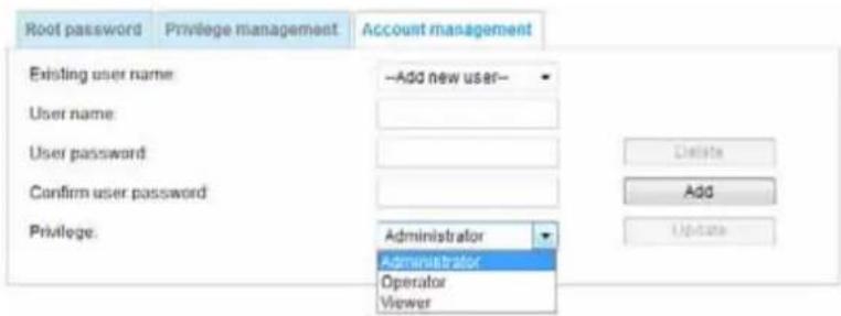
Administrators can add up to 20 user accounts.
- Input the new user's name and password.
- Select the privilege level for the new user account. Click Add to enable the setting.
Access rights are sorted by user privilege (Administrator, Operator, and Viewer). Only administrators can access the Configuration page. Although operators cannot access the Configuration page, they can use the URL Commands to get and set the value of parameters. For more information, please refer to URL Commands of the Network Camera on page 117. Viewers access only the main page for live viewing.
Here you also can change a user's access rights or delete user accounts.
- Select an existing account to modify.
- Make necessary changes and click Update or Delete to enable the setting.
Security > HTTPS (Hypertext Transfer Protocol over SSL)
Advanced Mode
This section explains how to enable authentication and encrypted communication over SSL (Secure Socket Layer). It helps protect streaming data transmission over the Internet on higher security level.
Create and Install Certificate Method
Before using HTTPS for communication with the Network Camera, a Certificate must be created first. There are three ways to create and install a certificate:
Create self-signed certificate
- Select this option from a pull-down menu.
- In the first column, select Enable HTTPS secure connection, then select a connection option: "HTTP & HTTPS" or "HTTPS only".
- Click Create certificate to generate a certificate.
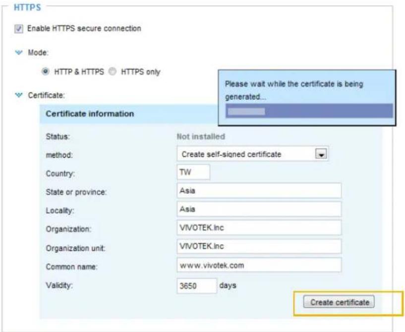
- The Certificate Information will automatically be displayed as shown below. You can click Certificate properties to view detailed information about the certificate.
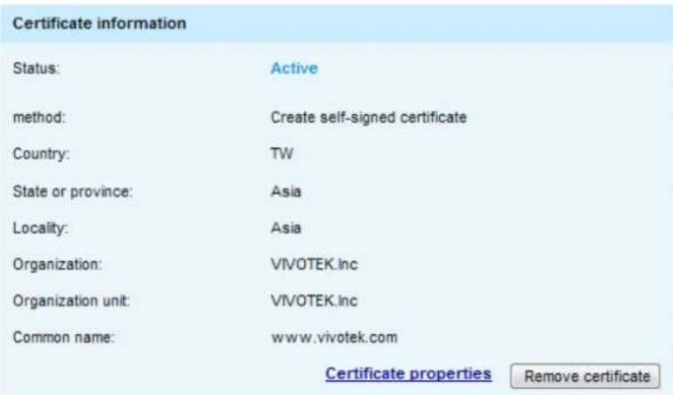
- Click Save to preserve your configuration, and your current session with the camera will change to the encrypted connection.
- If your web session does not automatically change to an encrypted HTTPS session, click Home to return to the main page. Change the URL address from "http://" to "https://" in the address bar and press Enter on your keyboard. Some Security Alert dialogs will pop up. Click OK or Yes to enable HTTPS.
https://
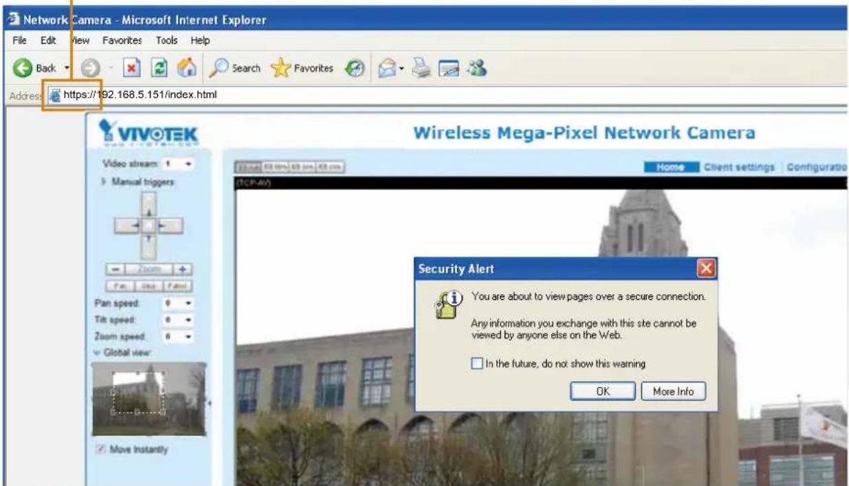
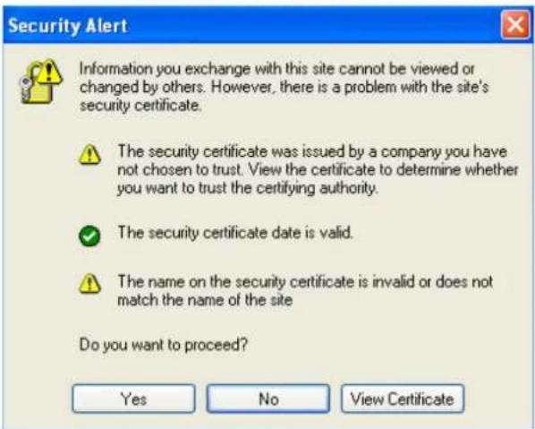
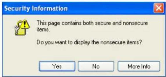
Create certificate request and install
- Select the option from the Method pull-down menu.
- Click Create certificate to proceed.
- The following information will show up in a pop-up window after clicking Create. Then click Save to generate the certificate request.
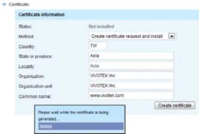
- The Certificate request window will prompt.
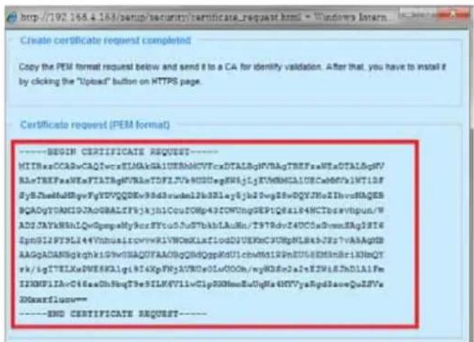
If you see the following Information bar, click OK and click on the Information bar at the top of the page to allow pop-ups.
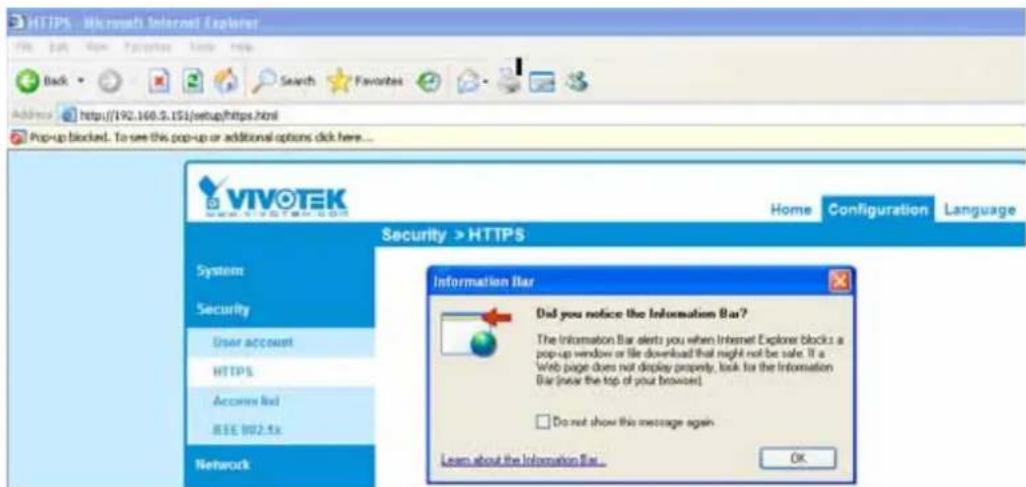
- Look for a trusted certificate authority, such as Symantec's VeriSign Authentication Services, that issues digital certificates. Sign in and purchase the SSL certification service. Copy the certificate request from your request prompt and paste it in the CA's signing request window. Proceed with the rest of the process as CA's instructions on their webpage.
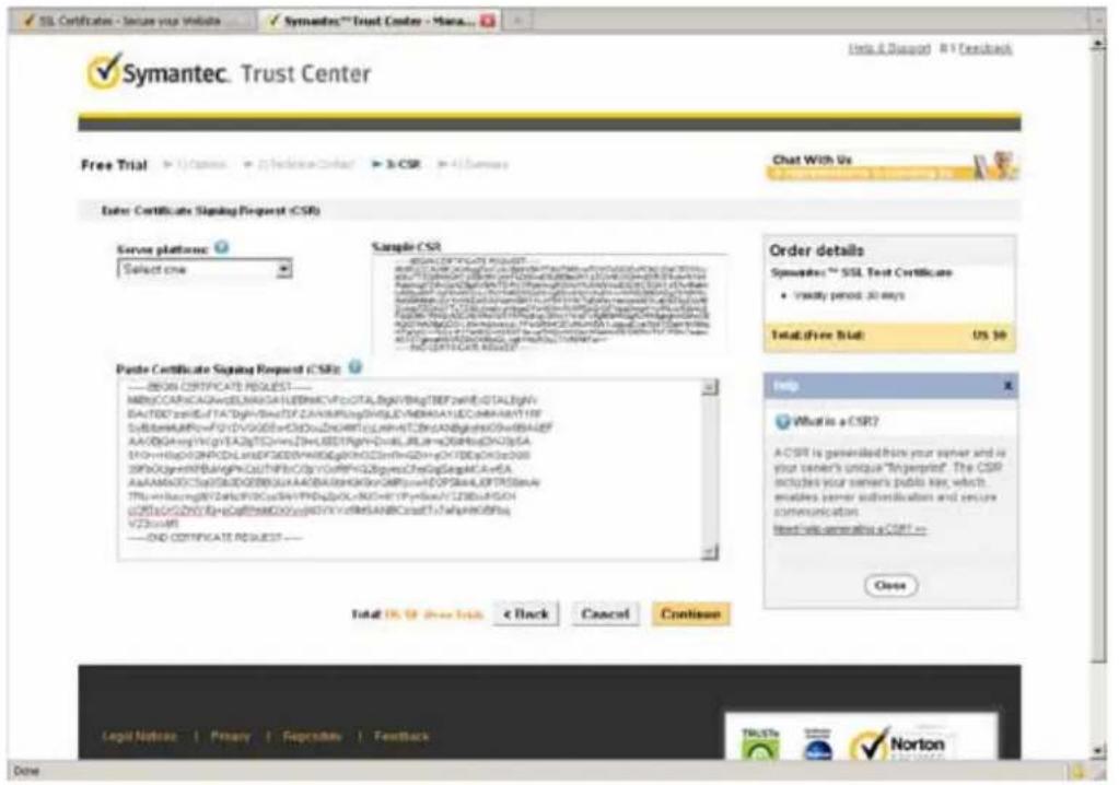
- Once completed, your SSL certificate should be delivered to you via an email or other means. Copy the contents of the certificate in the email and paste it in a text/HTML/hex editor/converter, such as IDM Computer Solutions' UltraEdit.
immediately, please dial 866.893.4543 or 650.426.5112 option 3 or send an email to internet-sales@verisign.com
Thank you for your interest in Symanter!
----BEGIN CERTIFICATE----
MIFNOCCA::qvpAldQAQfCalCahn/BrB15WQDQILsRbGpHk10WgBAQFADCB qvpLMAQALUENHCVVwEaVgVtNAeT0111c1taAinsLCdSntelTAcldYgVtQGL EydRc31gVpVndCBQsLwC NlcyEFmca3LAgTmbyKfsNckKtnmNlcy4x2gABdPv BaaTEV011111189mNtV2B86CbD8ksRwCecrOc7d3dy02KcXpIbnb5h2eV073Rs L3RicLrBYAaVykvGTENcaVAlDEAdWmVyaWlpI2agPbWpIWygUZyAII1PfI cnli1SQQAATEcYbSAKDTeyhDCwtAvaHDAAMToKDEYpDcwtYIsHKtLVWgw4x CtAJBgPbVTAALRXQvCwVTVQIEwBCs1lMnQvCWYHFARb21hdGUwEVYD VgQHYAFNTVYFEVLLeiLyty4xPTAtpBVSAoDFGfYvWnHGngSNtlyJyFNDgHA10E CKaWvTVQkBDqYpsNcI1F0F038dyI2X2KpcIainbIjn20rTVBaLSRlcXrtJY3As TywHETHXBGUALAGAxQsdIaLcDOE85H12tg0gVbQWuWflWcvtQABEQHBd yGAANIGDGAABHIdCoTcBdGfc-dhaAVTPVptHKDcYtsTaZunByLpdisIade60qDg pH+ayhtpTUgGSTIMwADRBSCFq/4xIPbQeGpWg5020GB/qgtmARKy1xwkPKn/B WakLINsLeVoIoCypxRaRCHQ-w4505DeRaHSdAbuHapgAkoBOhoNqzAgPdBAQ ggPHSHITACTWvSPBEEECEqGppHsdolcmDHCycLshnuTJALWgBHVEEAJAAAG4G AldHoEvwVqKAIFeTCBCGyVHRSGEAGHCglgAChj2edHHoEtVfU157Fv3PyrAm BaTsYtJaLnIcmlsaAwLiLeNbVt59TV1JtcUmlhbCyLshyDHRRGvNHFRAEJAAAG4G CMCSAGG-EKBHwMTNtAeTpgrEPgFCq(CAQAY)AvRIODMALYk3dsmdm/YakHpI24a T2YtL2WcyTGSDHY2BdQyDV0YBJDYAVBQDAaADGCsAGQTHeCHBB AldTvQdRbAaPCpKgEq9lgQJAYArTaZdaHHMtTlHQQQCCGACFpWRnEBDGpv2jAk BspRgEPgECQwCYtYYAaTCbcovLjycAcMdwYxaHpI24aNfPbHD4CCsAGQTHeAC bj7odHHoQtVfTl2FVPsYWaTetYNhLaIcmlsaAwLiNbVt59TV1JtcUmlhbCy LeiklyAaRqquenidWvSAQFAQPAeCAatUnTsnleX/TxtSerxXnELKSdPp qaqSewSwacI2IpPrSyErPe6TCLPdHerOPGyIaLFpAEUTTrSEICsCKNRBJApy12 qVhFBqFvgWNMeT7s4doUByarnafidShTvbubQz7tbyMeANhAH/P+euO5EveBra cfAhn/hqsqnogCkNytwcyeCNW8pgotSci368qKpPassrTowRajhpdaESUCAs 3RLJCKrsAgVtRadif-PLgtHgUg2AgNgaKcnTchNHcNAvgBnNucelII03TTRPCT nc6GlnylblgmfpYhRgVytDoVfZImn285qdu5qlsJAAPR/gi//XeRp=
- Open a new edit, paste the certificate contents, and press ENTER at the end of the contents to add an empty line.
![[Edit1*] - UltralEdit File Edit Search Insert Project View Format Column Macro Scripting Advanced Window Help Project Open Explorer Lists Filter: A: B: C: D: E: F: Network: FTP Accounts Name Date modification Edit1* CmCGSAGG+EUBBxUwHTAvBggrBgEFBQcCARTJaHROcHM6Ly93d3cudmVyaJNpZ24u Y29tL2Nwcy90ZXN0T2xEwHQY6VR01BBTwFAYIKwYBBQUNAwEGCCsGAQUFBwMCND0G AlUdIwQYMBaAFCgXE4q91qK13AYst7a02h8mYG71MHQGCCsGAQUFBwEBBGgwTjAk BggrBgEFBQcwAYYYaHROdoDovL29jo3AudevVyaJNpZ24uY29tHD40CCsGAQUFBzAC hjJodHRwOiDvU1ZSVHJpYWwtRzltYv1hLnZlcmlaWduLnNbDS9TViJUcslhbEcy LmN1c3ANBgkqhx1G9wQBAQUFAAOCAQATxuH7FnIme/X7T6z/zsr9tZEhLKSEQSp qnaNoHnwixRcl2HPp3ksEKvp6TCLPSMrcOP0jPalLFxAKUITr3WlBCoXWRlAjNp12 qVUSBdfxgVMWx9T7rd2oURjms61fcM5Ttu3Qc2TulpWeARbAH/U+x+ojGOEvB3t ePamShn/qdapEcq00xVBycwHeCWNSRQgmGc1368qKPezmv7oErbnLhupjdxUEBSGExu 3M13CXrAtQ2v1RedifJQYSTgSONqIma9ghdKuKTnhCHUewgOxNNureIIB3ITPK70 m6CoTpntb1qmFtyj9EvgIUdc6YfImn2BOq3c5q3iFARPH/gi///XeGg== ----END CERTIFICATE---- Caoio Heli Macio Heli Sort List XML Manager](/content/2026/06/1186415/images/d6e51bc1271ff560484d84639d7a4d42c0b38baa3a35221ea0afd2dc0a48c9cc.jpg)
- Convert file format from DOS to UNIX. Open File menu > Conversions > DOS to Unix.
![[Edit1*] - UltratEdit File Edit Search Insert Project View Format Column Macro Scripting Advanced Window Help Name Ctrl+N Open... Ctrl+O Quick Open... Ctrl+Q Close Close All Files Ctrl+Shift+F4 Close All Files Except Tgs F[P/Telnet Write to Save] Save Ctrl+S Save As... F12 Save All Alt+F12 Save Copy/Backup Encryption Rename File Coppare... Alt+F11 Sort Conversions Special Functions Print... Ctrl+P Print All Files Print Preview Print Setup/Configuration Favorite Files... Ctrl+Shift+F Recent Files Recent Projects/WorkSpace Cut 18 24 36 40 54 68 84 GNAGG+EUBEXUwNTAvRggrBgEFBQoCARYJaNROcHM6Ly93dJcoudeVyaXNpZZ4u tL2Nwcy90ZZNOTZEwBOYDVRO1BBTyFAYIKwYBBQUHAvEGCCsGAQUFBwBCHB0G diWQYMBaAPCcXE4q91qK13AYst7a02hBmY071MHQGCCsGAQUFBwEBBGgwZjAk rBgEFBQcwAYYYTaNROcDovL29jc2AudmVyaJNpZZ4uY29tMD4GCCsGAQUFBzAC pdHRwOv8vU1ZSVHJPYWwtRzItYWlhLnIcmlzaWduLnNbS9TV1JUcmllhbEcy lojANBgkghkiOGWwDBAQUFAAOCACKATxuH7FnIme/X7T6s/zsr9sEKhLKSEQRp cBavixSc129Pp3kzEKvp6TCLPGMbrOPGjPaILFxAEUITr3VIBCoXVR1AjVp12 bDfxgVWx91Trd2oURzjms61fcH5Tcub3Qe2Tu3pVeAKbAR/U+x+ojGOEvB3s thn/qcapKoq02vNyceVHeCWNbRQgsGe1368qkPssav7oXrbnl.hupjdxUKSOKxu DCXrAtQZv1RadiifJQYSTg50Nq2mk9ghdFuKTnhCHUwqwOxN8uceIIB3ITPK70 yPntblgmPtyj9EvgIUdc6YZImn2ROqSe5q3iZABPH/gi//ZeGg-- --END CERTIFICATE---- UND/MAC to DOS DOS to MAC DOS to UNIX EDCDIC to ASCII ASCII to EDCDIC OEM to AIGI ANSI to OEM ASCII to Unicode UTF-8 to Unipool Unicode to ABCD template List Global Power User](/content/2026/06/1186415/images/a2c0aeaec3b49dbf48fec70c1e98211e5fd99299ed6ea8f9b62fcf85af23177d.jpg)
- Save the edit using the ".crt" extension, using a file name like "CAcert.crt."
![[C:\Documents and Settings\we3c\Desktop\ files201*] - Altiaids File Edit Tools Insert Prompt View Paste Colors Mode Navigation Advanced Version Help Save As Project Open Explorer Lists Filter: A: C: D: E: F: Network FTP Accounts Save as: Desktop My Documents My Computer My Network Places Adobe Reader 9 File26a Client Google Chrome Installation Wizard 2 LiveClient McAfee Security Scan Plus Milestone XProtect Smart Client Mozilla Firefox Playback QuickTime Player RealPlayer TeamViewer 6 UltraCompare UltraEdit VIVO-TEX BlackholePM公用资料文 (位於 Blackhole) New Folder 44 45 46 802.1x 802.1x-1 802.1x-2 802.1x-3 access_alet activeX_plugin activeX_plugin1 File name: CAcet.cs Save as type: All Files (*.*) Save Cancel Line Terminator: Default Format: Default ADS Stream: All Data (Stream is only for files on https.dwg)](/content/2026/06/1186415/images/d26b2dab34223b5320bc01ba95890a9ef9a93e66e3647ddf0df9263ce9369569.jpg)
- Return to the original firmware session, use the Browse button to locate the crt certificate file, and click Upload to enable the certification.
![Home Client settings Configuration Language Security > HTTPS System Media Network Security User accounts HTTPS Access list IEEE 802.txt PTZ [vent] Applications Recording Local storage [ Basic mode ] Version 0100c HTTPS Enable HTTPS secure connection Mode: HTTP & HTTPS HTTPS only Certificate: Certificate information Status: Waiting for certificated Select certificate file: C:\Documents and 8e Browse Upload Method: Create certificate request and install Country: TW State or province: Asia Locality: Asia Organization: VIVOTEK Inc. Organization unit: VIVOTEK Inc. Common name: www.vivotek.com Remove certificate](/content/2026/06/1186415/images/b7bb32c45dfab2e5b7d58cddc94fcb5ed2b850ce5bd6d30b0e7a9c308504090c.jpg)
- When the certificate file is successfully loaded, its status will be stated as Active. Note that a certificate must have been created and installed before you can click on the "Save" button for the configuration to take effect.
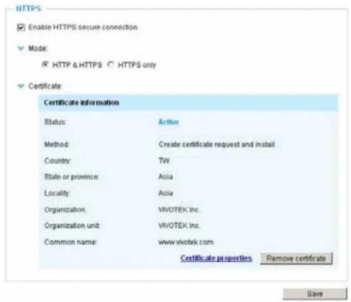
- To begin an encrypted HTTPS session, click Home to return to the main page. Change the URL address from "http://" to "https://" in the address bar and press Enter on your keyboard. Some Security Alert dialogs will pop up. Click OK or Yes to enable HTTPS.
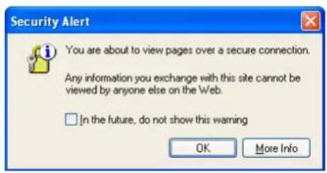
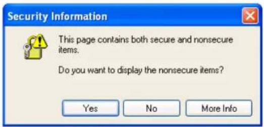
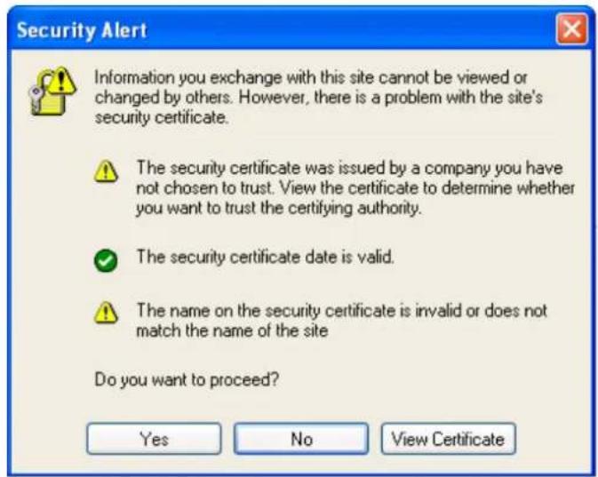
Enable HTTPS
Check this item to enable HTTPS communication, then select a connection option: "HTTP & HTTPS" or "HTTPS only". Note that you have to create and install a certificate first before clicking the Save button.
Enable HTTPS

Enable HTTPS secure connection:

HTTP & HTTPS Ⓞ HTTPS only
Save
Security > Access List Advanced Mode
This section explains how to control access permission by verifying the client PC's IP address.
General Settings

Maximum number of concurrent streaming connection(s) limited to: Simultaneous live viewing for 1\~10 clients (including stream 1 and stream 2). The default value is 10. If you modify the value and click Save, all current connections will be disconnected and automatically attempt to re-link (IE Explore or Quick Time Player).
Connection management Click this button to display the connection status window showing a list of the current connections. For example:
| IP address | Elapsed time | User ID | |
| 192.168.4.150 | 00:00:51 | ||
| 192.168.4.124 | 00:00:06 |

Note that only the consoles that are currently displaying live streaming will be listed in the management list.
■ IP address: Current connections to the Network Camera.
■ Elapsed time: How much time the client has been at the webpage.
■ User ID: If the administrator has set a password for the webpage, the clients have to enter a user name and password to access the live video. The user name will be displayed in the User ID column. If the administrator allows clients to link to the webpage without a user name and password, the User ID column will be empty.
There are some situations that allow clients access to the live video without a user name and password:
-
The administrator does not set up a root password. For more information about how to set up a root password and manage user accounts, please refer to Security -> User account on page 73.
-
The administrator has set up a root password, but set RTSP Authentication to "disable". For more information about RTSP Authentication, please refer to RTSP Streaming on page 64.
-
The administrator has set up a root password, but allows anonymous viewing. For more information about Allow Anonymous Viewing, please refer to page 73.
■ Refresh: Click this button to refresh all current connections.
■ Add to deny list: You can select entries from the Connection Status list and add them to the Deny List to deny access. Please note that those checked connections will only be disconnected temporarily and will automatically try to re-link again (IE Explore or Quick Time Player). If you want to enable the denied list, please check Enable access list filtering and click Save in the first column.
■ Disconnect: If you want to break off the current connections, please select them and click this button. Please note that those checked connections will only be disconnected temporarily and will automatically try to re-link again (IE Explorer or Quick Time Player).
Enable access list filtering: Check this item and click Save if you want to enable the access list filtering function.
Filter
Filter type: Select Allow or Deny as the filter type. If you choose Allow Type, only those clients whose IP addresses are on the Access List below can access the Network Camera, and the others cannot access. On the contrary, if you choose Deny Type, those clients whose IP addresses are on the Access List below will not be allowed to access the Network Camera, and the others can access.
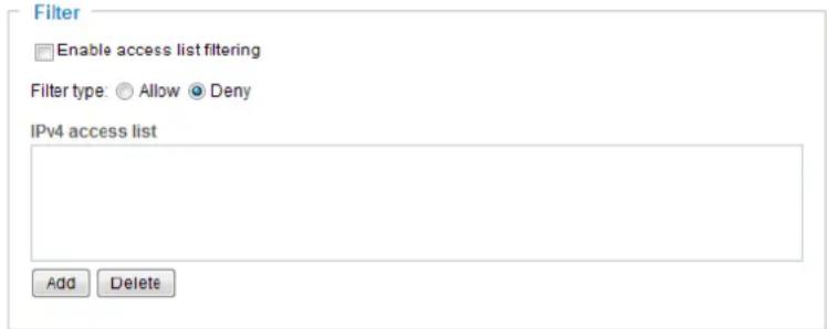
Then you can Add a rule to the following Access List. Please note that the IPv6 access list column will not be displayed unless you enable IPv6 on the Network page. For more information about IPv6 Settings, please refer to Network -> General settings on page 56 for detailed information.
Please select the Enable access list filtering checkbox for your configuration to take effect.
There are three types of rules:
Single: This rule allows the user to add an IP address to the Allowed/Denied list.
For example:
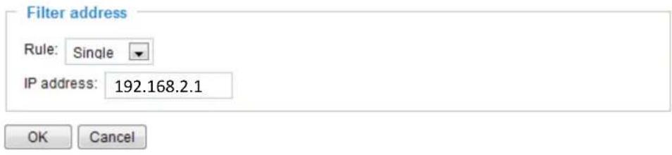
Network: This rule allows the user to assign a network address and corresponding subnet mask to the Allow/Deny List. The address and network mask are written in CIDR format.
For example:
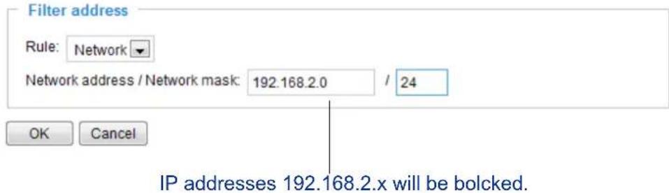
Range: This rule allows the user to assign a range of IP addresses to the Allow/Deny List.
Note: This rule is only applied to IPv4.
For example:
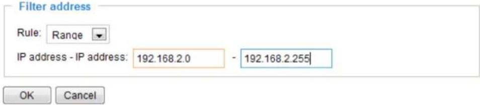
Administrator IP address
Always allow the IP address to access this device: You can check this item and add the Administrator's IP address in this field to make sure the Administrator can always connect to the device.

Security > IEEE 802.1X Advanced Mode
Enable this function if your network environment uses IEEE 802.1x, which is a port-based network access control. The network devices, intermediary switch/access point/hub, and RADIUS server must support and enable 802.1x settings.
The 802.1x standard is designed to enhance the security of local area networks, which provides authentication to network devices (clients) attached to a network port (wired or wireless). If all certificates between client and server are verified, a point-to-point connection will be enabled; if authentication fails, access on that port will be prohibited. 802.1x utilizes an existing protocol, the Extensible Authentication Protocol (EAP), to facilitate communication.
■ The components of a protected network with 802.1x authentication:
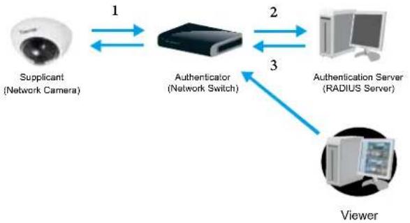
flowchart
graph LR
    A["Supplicant\n(Network Camera)"] -->|1| B["Authenticator\n(Network Switch)"]
    B -->|2| C["Authentication Server\n(RADIUS Server)"]
    C -->|3| D["Viewer"]
-
Supplicant: A client end user (camera), which requests authentication.
-
Authenticator (an access point or a switch): A "go between" which restricts unauthorized end users from communicating with the authentication server.
-
Authentication server (usually a RADIUS server): Checks the client certificate and decides whether to accept the end user's access request.
■ VIVOTEK Network Cameras support two types of EAP methods to perform authentication: EAP-PEAP and EAP-TLS.
Please follow the steps below to enable 802.1x settings:
-
Before connecting the Network Camera to the protected network with 802.1x, please apply a digital certificate from a Certificate Authority (i.e., your network administrator) which can be validated by a RADIUS server.
-
Connect the Network Camera to a PC or notebook outside of the protected LAN. Open the configuration page of the Network Camera as shown below. Select EAP-PEAP or EAP-TLS as the EAP method. In the following blanks, enter your ID and password issued by the CA, then upload related certificate(s).
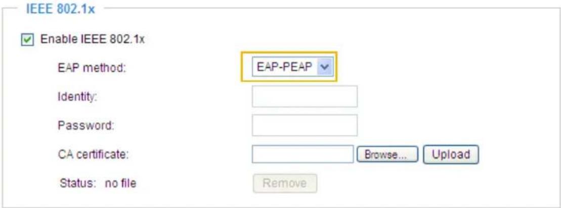
IEEE 802.1x

Enable 802.1x
EAP method:
Identity:
Private key passord:
CA certificate:
Status: no file
client certificate:
Status: no file
Client private key:
Status: no file
EAP-TLS
Browse.
Upload
Remove
Browse.
Upload
Remove
Browse.
Upload
Remove
- When all settings are complete, move the Network Camera to the protected LAN by connecting it to an 802.1x enabled switch. The devices will then start the authentication automatically.

NOTE:
▶ The authentication process for 802.1x is as follows:
- The Certificate Authority (CA) provides the required signed certificates to the Network Camera (the supplicant) and the RADIUS Server (the authentication server).
- A Network Camera requests access to the protected LAN using 802.1X via a switch (the authenticator). The client offers its identity and client certificate, which is then forwarded by the switch to the RADIUS Server, which uses an algorithm to authenticate the Network Camera and returns an acceptance or rejection back to the switch.
- The switch also forwards the RADIUS Server's certificate to the Network Camera.
- Assuming all certificates are validated, the switch then changes the Network Camera's state to authorized and is allowed access to the protected network via a pre-configured port.
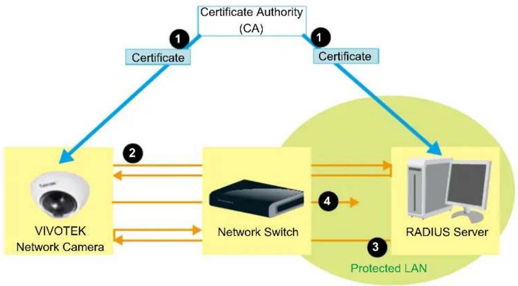
flowchart
graph TD
    A["Certificate"] --> B["VIVOTEK Network Camera"]
    A --> C["Certificate Authority (CA)"]
    C --> D["Network Switch"]
    D --> E["RADIUS Server"]
    E --> F["Protected LAN"]
    F --> D
    style A fill:#f9f,stroke:#333
    style C fill:#f9f,stroke:#333
    style D fill:#ccf,stroke:#333
    style E fill:#cfc,stroke:#333
    style F fill:#fcc,stroke:#333
PTZ > PTZ settings
Advanced Mode
This section explains how to control the Network Camera's Pan/Tilt/Zoom operation.
There are two ways to enable the function:
The Digital name tag refers to the e-PTZ operation. It allows users to quickly move the focus to a target area for close-up viewing when the current field of view is smaller than the camera's maximum output frame size.
Digital PTZ Operation (E-PTZ Operation)
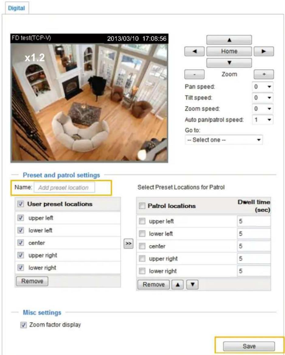
Please note that only stream #1 can possess its own preset and patrol settings. For detailed information about how to set up preset and patrol settings, please refer to page 87.
Auto pan/patrol speed: Select the speed from 1\~5 (slow/fast) to set up the Auto pan/patrol speed control.
When completed with the e-PTZ settings, click Save to enable the settings on this page.
Home page in E-PTZ Mode
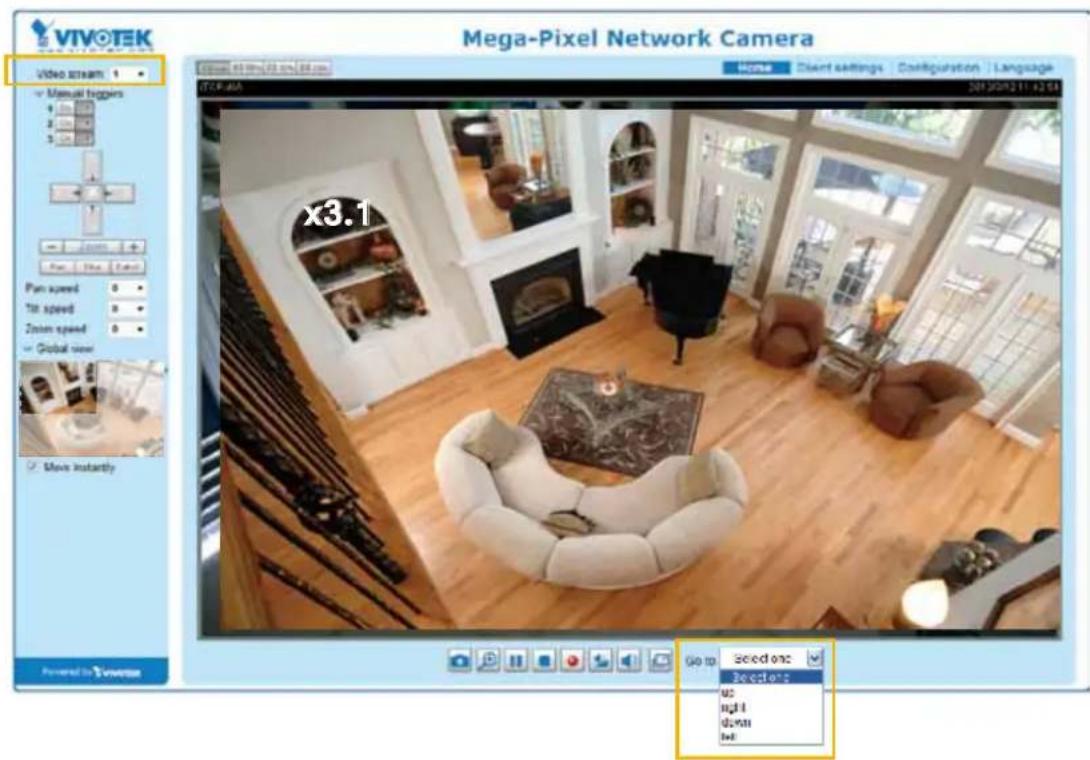
■ The e-Preset Positions will also be displayed on the home page. Select one from the drop-down list, and the Network Camera will move to the selected e-preset position.
Global View
In addition to using the e-PTZ control panel, you can also use the mouse to drag or resize the floating frame to pan/tilt/zoom on the viewing region. The live view window will also move to the viewing region accordingly.
Moving Instantly
If you check this item, the live view window will switch to the new viewing region instantly after you move the floating frame. If not selected, the live view window will display the progress moving from one spot to another. However, the progress is not easily seen if the move is made across a small field of view.
Click on Image
The e-PTZ function also supports "Click on Image". When you click on any point of the Global View Window or Live View Window, the viewing region will also move to that point.
Note that the "Click on Image" function only applies when you have configured a smaller "Region of Interest" out of the maximum output frame, e.g., a 800x600 region from the camera's 1920x1080 maximum frame size.
Patrol settings
You can select some preset positions for the Network Camera to patrol.
Please follow the steps below to set up a patrol schedule:
- Select the preset locations on the list, and click >>.
- The selected preset locations will be displayed on the Patrol locations list.
- Set the Dwelling time for the preset location during auto patrol.
-
If you want to delete a preset location from the Patrol locations list, select it and click Remove.
-
Select a location and click ▲ ▼ to rearrange the patrol order.
-
Select patrol locations you want to save in the list and click Save to enable the patrol settings.
-
To implement the patrol schedule, please go to homepage and click on Patrol button. Please refer to the next page.
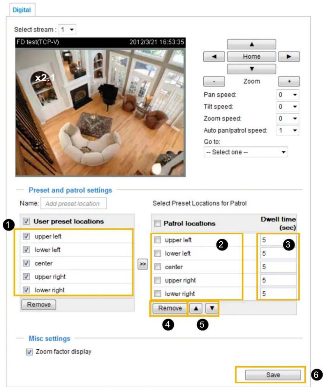
Home page in the e-PTZ Mode
The Preset positions will also be displayed on the home page. Select one from the Go to drop-down list, and the Network Camera will move to the selected preset position.
Patrol button: Click this button, then the Network Camera will patrol among the selected preset positions continuously.
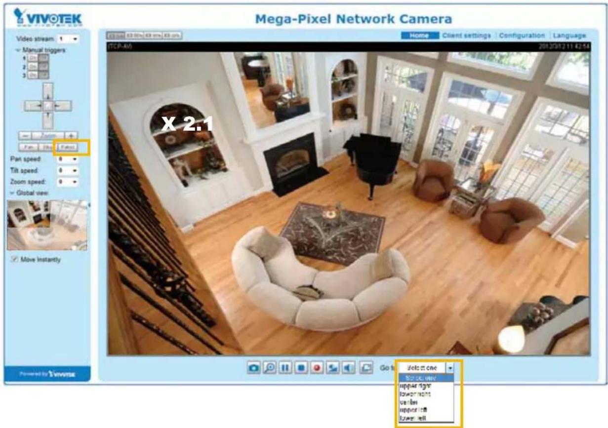

NOTE:
The Preset Positions will also be displayed on the home page. Select one from the Go to drop-down list, and the Network Camera will move to the selected preset position.
The Patrol button: The Network Camera will patrol along the selected positions repeatedly. Please refer to page 89 for more information.
Event > Event settings
Advanced Mode
This section explains how to configure the Network Camera to responds to particular situations (events). A typical application is that when a motion is detected, the Network Camera sends buffered images to an FTP server or e-mail address as event notifications. Click on Help, there is an illustration shown in the pop-up window explaining that an event can be triggered by many sources, such as motion detection or external digital input devices. When an event is triggered, you can specify what type of action that will be performed. You can configure the Network Camera to send snapshot images to your email address or send video clips to an FTP site.
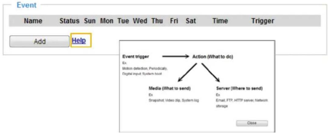
Event
To configure an event with recorded video or snapshots, it is necessary to configure the server and media settings so that the Network Camera will know what action to take (such as which server to send the media files to) when a trigger is activated. An event is an action initiated by a user-defined trigger source. In the Event column, click Add to open the event settings window. Here you can arrange three elements -- Schedule, Trigger, and Action to set an event. A total of 3 event settings can be configured.
![Event Name Status Sun Mon Tue Wed Thu Fri Sat Time Trigger Add Help Event name: Enable this event Priority Normal Detect next motion detection or digital input after 10 seconds 1. Schedule 2. Trigger 3. Action Event Schedule Sun Mon Tue Wed Thu Fri Sat Time Always From 24:00 to 24:00 [hh:mm] Close Save event](/content/2026/06/1186415/images/0253526d29e3620e37ffb087c099f7903798f02f6d7250de500cfd1cb412cc17.jpg)
■ Event name: Enter a name for the event setting.
■ Enable this event: Select this option to enable the event setting.
■ Priority: Select the relative importance of this event (High, Normal, or Low). Events with a higher priority setting will be executed first.
■ Detect next event after □ seconds: Enter the duration in seconds to pause motion detection after a motion is detected. This can prevent event-related actions to be too frequently performed.
1. Schedule
Specify the period of time during which the event trigger will take place. Please select the days of the week and the time in a day (in a 24-hr time format) for the event triggering schedule.
2. Trigger
This is the cause or stimulus which defines when to trigger the Network Camera. The trigger source can be configured to use the Network Camera's built-in motion detection mechanism or external digital input devices.
There are several choices of trigger sources as shown on the next page. Select the item to display the detailed configuration options.
■ Video motion detection
This option makes use of the built-in motion detection mechanism as a trigger source. To enable this function, you need to configure a Motion Detection Window first. For more information, please refer to Motion Detection on page 104 for details.
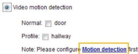
■ Periodically
This option allows the Network Camera to trigger an event periodically at the interval of configurable period of time. You can configure the interval into 1 to 999 minutes.
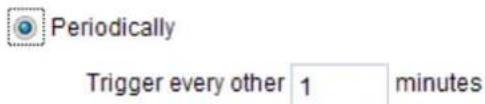
■ Digital input
This option allows the Network Camera to use an external digital input device or sensor as a triggering source. Depending on your application, there are many choices of digital input devices on the market which can help to detect changes in temperature, vibration, sound, and light, etc.
■ System boot
This option triggers the Network Camera when the power to the Network Camera was lost and is now connected.
■ Recording notify
This option allows the Network Camera to trigger when the recording disk is full or when recording starts to rewrite older data.
■ Camera tampering detection
This option allows the Network Camera to trigger when the camera detects that is is being tampered with. To enable this function, you need to configure the Tampering Detection first. Please refer to page 107 for detailed information.
![Camera tampering detection Enable camera tampering detection Trigger duration: 10 seconds [10-600] Save](/content/2026/06/1186415/images/c7eb7528afaae0c52481d202bec2d8ab54ce4dd91f2720eeaebdcfb51a5e5668.jpg)
■ Manual Trigger
This option allows users to enable event triggers manually by clicking the on/off button on the homepage. Please configure 1 to 3 associated events before using this function.
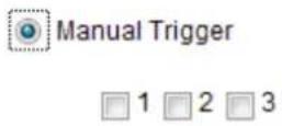
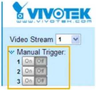
3. Action
Define the actions to be taken when a trigger is activated.
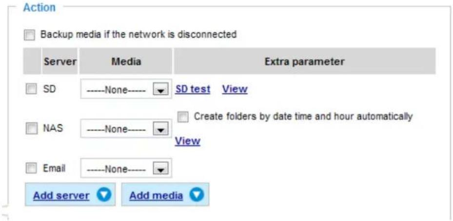
■ Backup media if the network is disconnected
Select this option to backup media file to the onboard SD card if the network is disconnected. This function will only be displayed after you set up an Action Server, such as a network storage (NAS).
Add server
To configure an event that will be recorded in video clips or snapshots, it is necessary to configure the server and media settings so that the Network Camera will know what action to take (such as which server to send the media files to) when a trigger is activated. Click Add server to open the server setting window. You can specify where the notification messages are sent when a trigger is activated. A total of 5 server settings can be configured.
There are four choices of server types available: Email, FTP, HTTP, and Network storage. Select the item to display the detailed configuration options. You can configure either one or all of them.
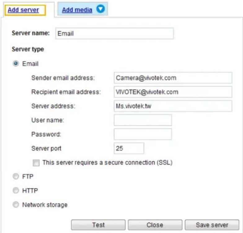
Server type - Email
Select to send the media files via email when a trigger is activated.
■ Server name: Enter a name for the server setting.
■ Sender email address: Enter the email address of the sender.
■ Recipient email address: Enter the email address of the recipient.
■ Server address: Enter the domain name or IP address of the email server.
■ User name: Enter the user name of the email account if necessary.
■ Password: Enter the password of the email account if necessary.
■ Server port: The default mail server port is set to 25. You can also manually set another port.
If your SMTP server requires a secure connection (SSL), check This server requires a secure connection (SSL).
To verify if the email settings are correctly configured, click Test. The result will be shown in a pop-up window. If successful, you will also receive an email indicating the result.
Click Save server to enable the settings.
Note that after you set up the first event server, the new event server will automatically display on the Server list. If you wish to add other server options, click the Add server button again.
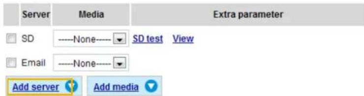
Server type - FTP
Select to send the media files to an FTP server when a trigger is activated.
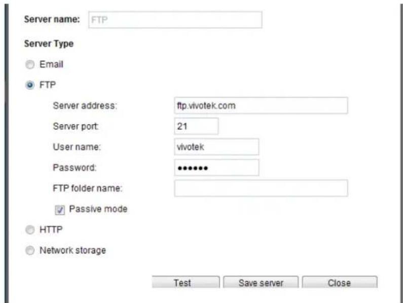
■ Server name: Enter a name for the server setting.
■ Server address: Enter the domain name or IP address of the FTP server.
■ Server port: By default, the FTP server port is set to 21. It can also be assigned to another port number between 1025 and 65535.
■ User name: Enter the login name of the FTP account.
■ Password: Enter the password of the FTP account.
■ FTP folder name
Enter the folder where the media file will be placed. If the folder name does not exist, the Network Camera will automatically create a folder on the FTP server.
■ Passive mode
Most firewalls do not accept new connections initiated from external requests. If the FTP server supports passive mode, select this option to enable passive mode FTP and allow data transmission to pass through the firewall. The firmware default has the Passive mode checkbox selected.
To verify if the FTP settings are correctly configured, click Test. The result will be shown in a pop-up window as shown below. If successful, you will also receive a test.txt file on the FTP server.
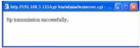
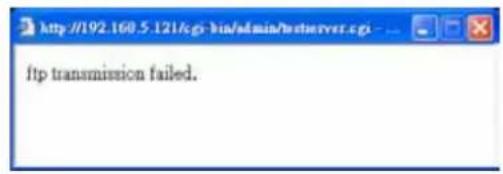
Click Save server to enable the settings.
Server type - HTTP
Select to send the media files to an HTTP server when a trigger is activated.
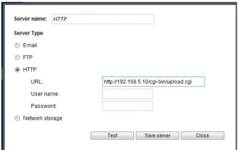
■ Server name: Enter a name for the server setting.
■ URL: Enter the URL of the HTTP server.
■ User name: Enter the user name if necessary.
■ Password: Enter the password if necessary.
To verify if the HTTP settings are correctly configured, click Test. The result will be shown in a pop-up window as below. If successful, you will receive a test.txt file on the HTTP server.
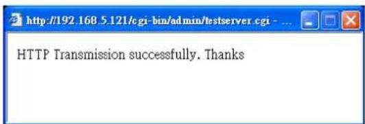
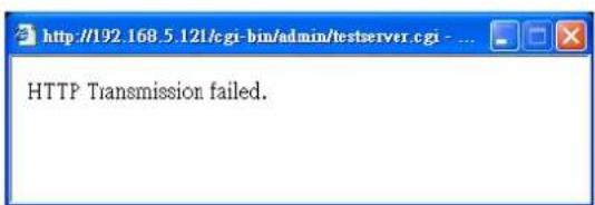
Click Save server to enable the settings.
Network storage:
Select to send the media files to a network storage location when a trigger is activated. Please refer to NAS server on page 111 for details.
Click Save server to enable the settings.
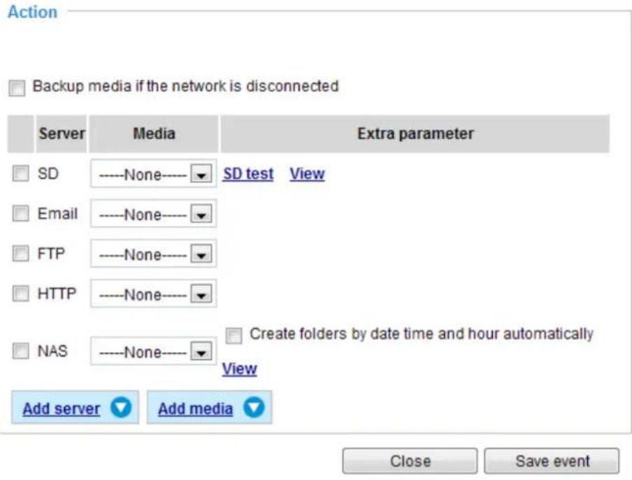
■ SD Test: Click to test your SD card. The system will display a message indicating success or failure. If you want to use your SD card for local storage, please format it before use. Please refer to page 99 for detailed information.
■ View: Click this button to open a file list window. This function is only for SD card and Network Storage. If you click the View button of SD card, a Local storage page will pop up for you to manage recorded files on SD card. For more information about Local storage, please refer to page 113. If you click the View button of Network storage, a file directory window will pop up for you to view recorded data on Network storage. For detailed illustration, please refer to the next page.
■ Create folders by date, time, and hour automatically: If you check this item, the system will generate folders automatically by the date when video footages are stored onto the networked storage.
The following is an example of a file destination containing video clips:
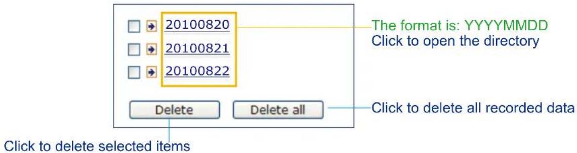
Click 20110220 to open the directory:
The format is: HH (24r)
Click to open the file list for that hour
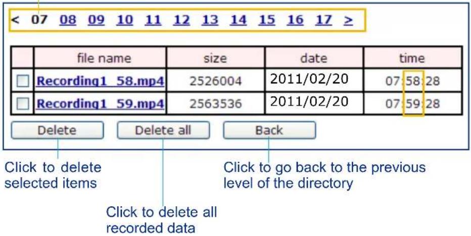
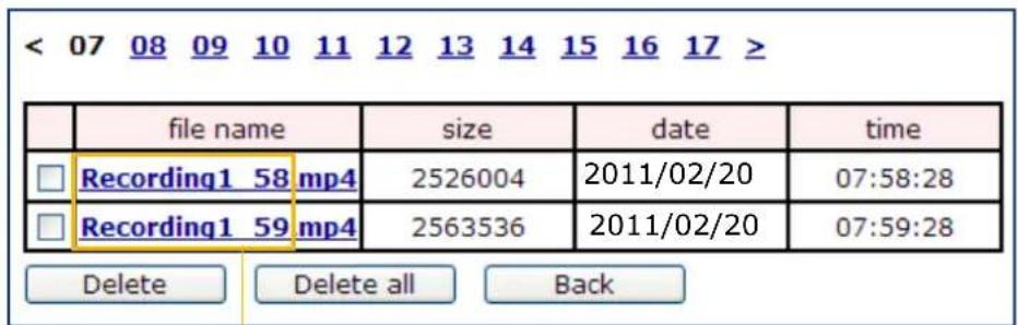
The format is: File name prefix + Minute (mm)
You can set up the file name prefix on Add media page. Please refer to next page for detailed information.
Add media
Click Add media to open the media setting window. You can specify the type of media that will be sent when a trigger is activated. A total of 5 media settings can be configured. There are three choices of media types available: Snapshot, Video Clip, and System log. Select the item to display the detailed configuration options. You can configure either one or all of them.
![Add server Add media Media name: Media type Attached media: Snapshot Source: Stream 1 Send 1 pre-event image(s) [0~7] Send 1 post-event image(s) [0~7] File name prefix: Snapshot_ ✓ Add date and time suffix to file name Video clip System log Close Save media](/content/2026/06/1186415/images/d7387ea38b4cd3106af00fcb790d8ee8bd5f7a0905d1130a67f5337f9af53468.jpg)
Media type - Snapshot
Select to send snapshots when a trigger is activated.
■ Media name: Enter a name for the media setting.
■ Source: Select to take snapshots from stream 1 \~ 2.
■ Send □ pre-event images
The Network Camera has a buffer area; it temporarily holds data up to a certain limit. Enter a number to decide how many images to capture before a trigger is activated. Up to 7 images can be generated.
■ Send □ post-event images
Enter a number to decide how many images to capture after a trigger is activated. Up to 7 images can be generated.
For example, if both the Send pre-event images and Send post-event images are set to 7, a total of 15 images are generated after a trigger is activated.

■ File name prefix
Enter the text that will be appended to the front of the file name.
■ Add date and time suffix to the file name
Select this option to add a date/time suffix to the file name.
For example:
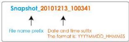
Click Save media to enable the settings.
To note that after you set up the first media server, a new column for media server will automatically appear on the Media list. If you wish to add more other media options, click Add media.
Media type - Video clip
Select to send video clips when a trigger is activated.
![Media name: video clip Media type Attached media: Snapshot Video clip Source: Stream 1 Pre-event recording: 0 seconds [0~9] Maximum duration: 5 seconds [1~20] Maximum file size: 500 Kbytes [50~4096] File name prefix: clip System log Save media Close](/content/2026/06/1186415/images/f060377d6d0d049f8a918eb15e3648f367a66ca61543d77f31a3e4695e7051dd.jpg)
■ Media name: Enter a name for the media setting.
■ Source: Select the source of video clip.
■ Pre-event recording
The Network Camera has a buffer area; it temporarily holds data up to a certain limit. Enter a number to decide the duration of recording before a trigger is activated. Up to 9 seconds can be set.
■ Maximum duration
Specify the maximum recording duration in seconds. Up to 10 seconds can be set.
For example, if pre-event recording is set to five seconds and the maximum duration is set to ten seconds, the Network Camera continues to record for another 4 seconds after a trigger is activated.
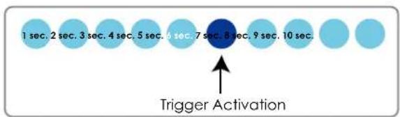
■ Maximum file size
Specify the maximum file size allowed.
■ File name prefix
Enter the text that will be appended to the front of the file name.
For example:
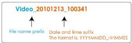
Click Save media to enable the settings.
Media type - System log
Select to send a system log when a trigger is activated.
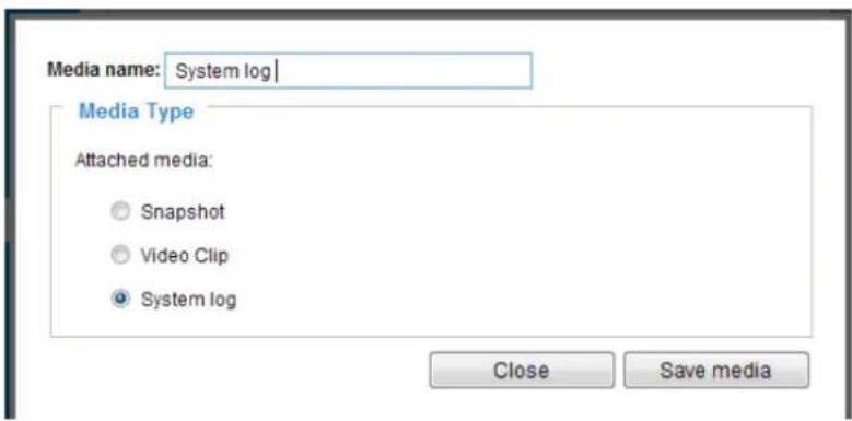
Click Save media to enable the settings, then click Close to exit the page.
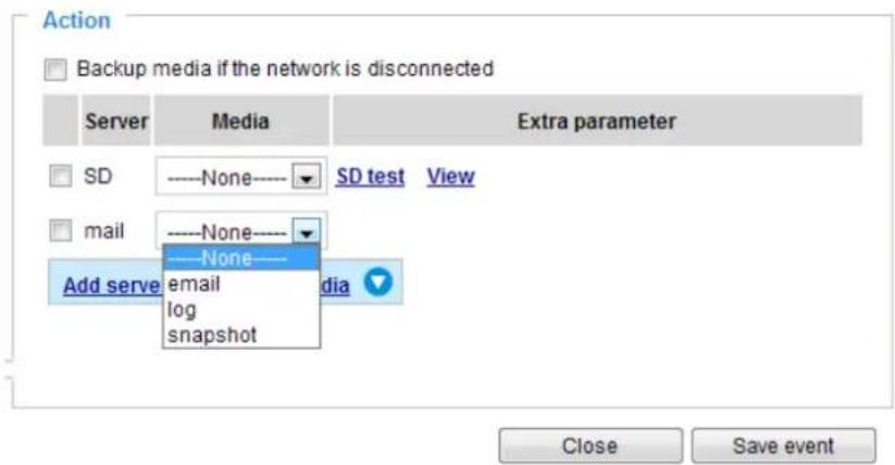
In the Event settings column, the Servers and Medias you configured will be listed; please make sure the Event -> Status is indicated as ON, in order to enable the event triggering action.
When completed, click Save event to enable the settings and click Close to exit Event Settings page. The new Event / Server settings / Media will appear in the event drop-down list on the Event setting page.
Please see the example of the Event setting page below:
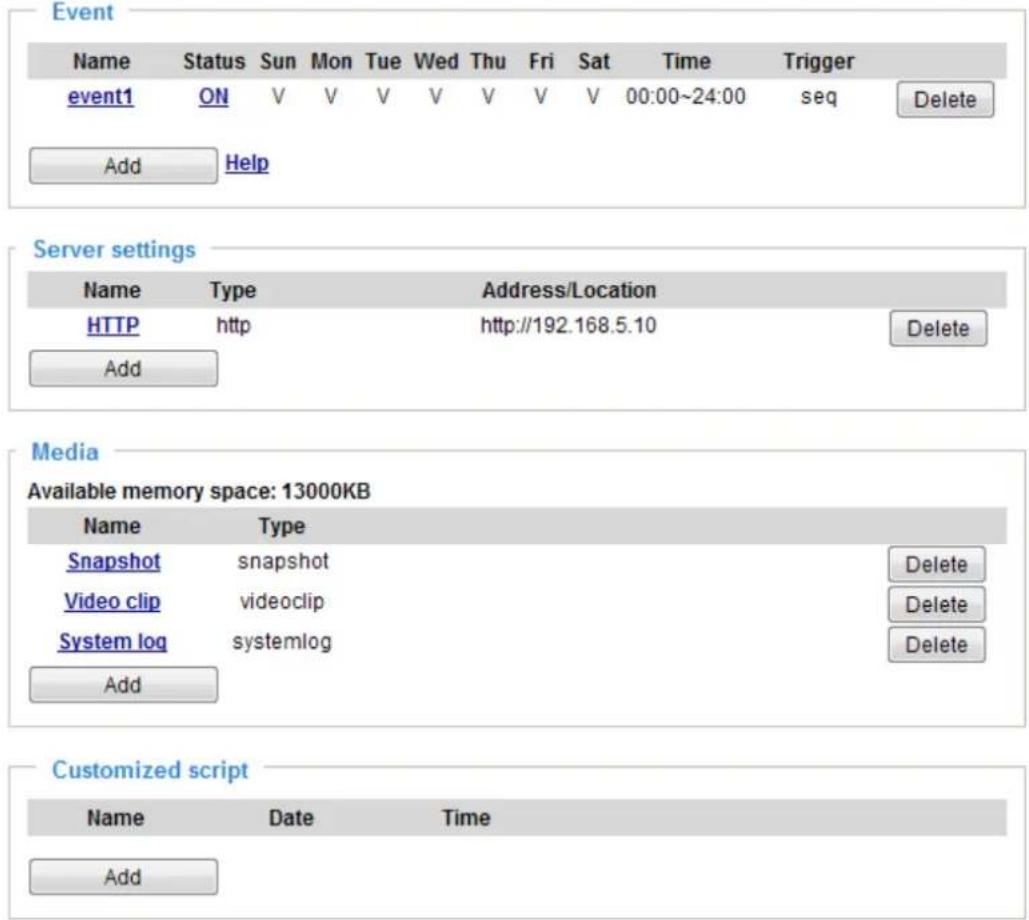
When the Event Status is ON, once an event is triggered by motion detection, the Network Camera will automatically send snapshots via e-mails.
If you want to stop the event trigger, you can click on the ON button to turn it to OFF status or click Delete to remove the event setting.
To remove a server setting from the list, select a server name from the drop-down list and click Delete. Note that you can only delete a server setting when it is not applied to an existing event setting.
To remove a media setting from the list, select a media name from the drop-down list and click Delete. Note that you can only delete a media setting when it is not applied to an existing event setting.
Customized Script
This function allows you to upload a sample script (.xml file) to the webpage, which will save your time on configuring the settings. Please note that there is a limited number of customized scripts you can upload; if the current amount of customized scripts has reached the limit, an alert message will prompt. If you need more information, please contact VIVOTEK technical support.
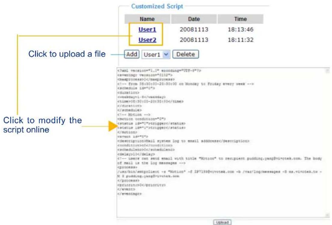
Applications > Motion detection
This section explains how to configure the Network Camera to enable motion detection. A total of three motion detection windows can be configured.
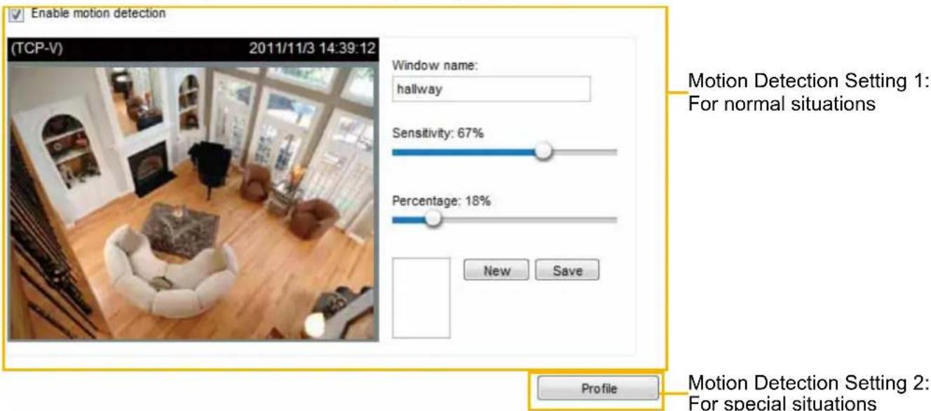
Follow the steps below to enable motion detection:
- Click New to add a new motion detection window.
- In the Window Name text box, enter a name for the motion detection window.
■ To move and resize the window, drag and drop your mouse on the window.
■ To delete a window, click the X mark on the upper right corner of the window.
- Define the sensitivity to moving objects and the space ratio of all alerted pixels by moving the Sensitivity and Percentage slider bar.
- Click Save to enable the settings.
- Select Enable motion detection to enable this function.
For example:
√ Enable motion detection
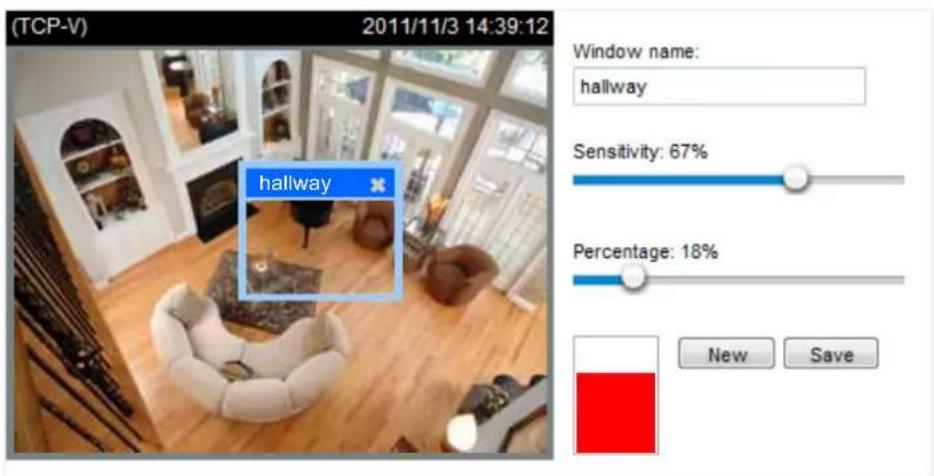
Profile
The Percentage Indicator will rise or fall depending on the variations between sequential images. When motions are detected by the Network Camera and are considered to have exceeded the defined threshold, the red bar rises. Meanwhile, the motion detection window will be outlined in red. Photos or videos can be captured instantly and configured to be sent to a remote server (Email, FTP) when using this feature as a trigger source. For more information on how to set an event, please refer to Event
settings on page 91.
A green bar indicates that even though motions have been detected, the event has not been triggered because the image variations still fall under the defined threshold.
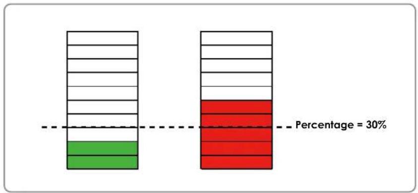
bar_stacked
| Category | Value | | -------- | ----- | | Green | 30% | | Red | 30% |If you want to configure other motion detection settings for a different time period within a day, please click Profile to open the Motion Detection Profile Settings page as shown below. A total of three motion detection windows can be configured on this page as well.
>Motion detection profile settings
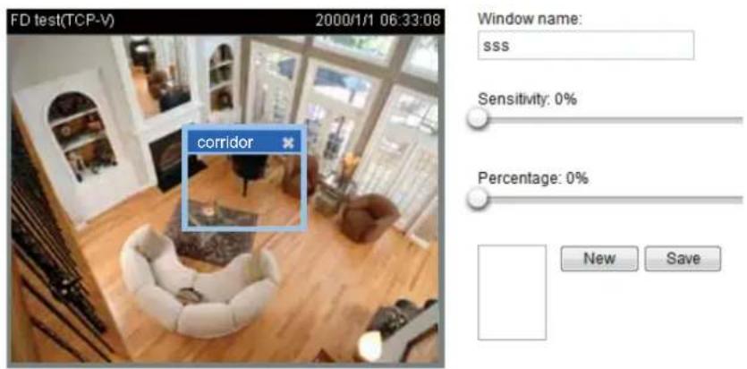
![General settings Enable this profile This profile is applied to: Schedule mode From 18:00 to 06:00 [hh:mm] Save Close](/content/2026/06/1186415/images/812071acdf81c86204a861f40d96d94d8ff36b13327c17183797ac5b4501adbf.jpg)
Please follow the steps beolw to set up a profile and additional motion detectio windows in it:
- Create a new motion detection window.
- Check Enable this profile.
- Select the applicable span of time in the Schedule mode. Please manually enter a time range if you choose Schedule mode.
- Click Save to enable the settings and click Close to exit the page.
This motion detection window will also be displayed on the Event Settings page. You can go to Event > Event settings > Trigger to choose it as a trigger source. Please refer to page 109 for detailed information.

NOTE:
▶ How does motion detection work?
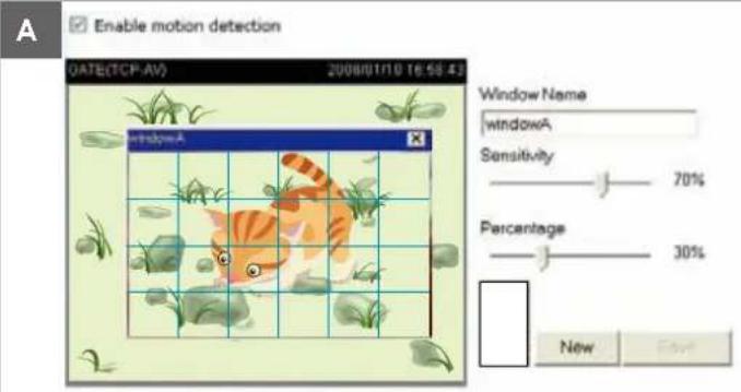
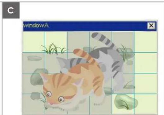
natural_image
Illustration of a cat playing with grass and leaves, displayed within a window labeled 'windowA' (no text or symbols on the image itself)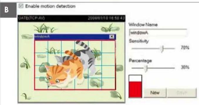
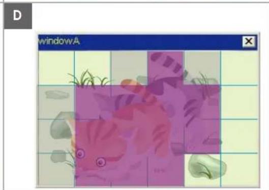
natural_image
Illustration of a cartoon fish with green grass and rocks, displayed within a grid interface (no text or symbols on the fish or background)There are two motion detection parameters: Sensitivity and Percentage. In the illustration above, frame A and frame B are two sequential images. Pixel differences between the two frames are detected and highlighted in gray (frame C) and will be compared with the sensitivity setting. Sensitivity is a value that expresses the sensitivity to moving objects. Higher sensitivity settings are expected to detect slight movements while smaller sensitivity settings will neglect them. When the sensitivity is set to 70%, the Network Camera defines the pixels in the purple areas as “alerted pixels” (frame D).
Percentage is a value that expresses the proportion of “alerted pixels” to all pixels in the motion detection window. In this case, 50% of pixels are identified as “alerted pixels”. When the percentage is set to 30%, the motions are judged to exceed the defined threshold; therefore, the motion window will be outlined in red.
For applications that require a high level of security management, it is suggested to use higher sensitivity settings and smaller percentage values.
Applications > Digital Input
Advanced Mode
Digital input
Normal status:

Current status:
High
Save
Connect a DI device to the camera's push-in type terminal block, the camera will automatically detect the current connection state as pulled-high or pulled-low. You may then define the Normal condition.
Normal status: Select High or Low to define the "Normal status" for the digital input. The Network Camera will report the current status below.
Applications > Tampering detection
This section explains how to set up camera tamper detection. With tamper detection, the camera is capable of detecting incidents such as redirection, blocking or defocusing, or even spray paint.
Camera tampering detection
Enable camera tampering detection
Trigger duration 10 seconds [10\~600]
Save
Please follow the steps below to set up the camera tamper detection function:
-
Check Enable camera tampering detection.
-
Enter the tamper trigger duration. (10 sec. \~ 10 min.) The tamper alarm will be triggered only when the tampering factor (the difference between current frame and pre-saved background) exceeds the trigger threshold.
-
You can configure Tampering Detection as a trigger element to the proactive event configurations in Event -> Event settings -> Trigger. For example, when the camera is tampered with, camera can be configured to send pre- and post-event video clips to a networked storage device. Please refer to page 109 for detailed information.
Recording > Recording settings Advanced Mode
This section explains how to configure the recording settings for the Network Camera.
Recording Settings
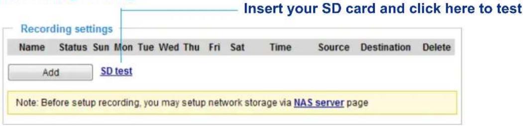

NOTE:
▶ Please remember to format your SD card when using it for the first time. Please refer to page 113 for detailed information.
Recording Settings
Click Add to open the recording setting window. On this page, you can define the adaptive recording, recording source, recording schedule, and recording capacity. A total of 2 recording settings can be configured.
![Recording name: Enable this recording With adaptive recording (Help) Pre-event recording: 5 seconds [0~9] Post-event recording: 5 seconds [0~10] Priority: Normal Source: Stream 1 1. Trigger 2. Destination Trigger Schedule Sun Mon Tue Wed Thu Fri Sat Time Always From 00:00 to 24:00 [hh:mm] Network fail Note: To enable recording notification please configure Event first Close Save](/content/2026/06/1186415/images/f9c8f8c342ecc3ccdd76a62f00cd2b7372cb4c70617a9cd4b85f7b14dfe259e0.jpg)
■ Recording name: Enter a name for the recording setting.
■ Enable this recording: Select this option to enable video recording.
■ With adaptive recording:
Selecting this option will activate the frame rate control according to alarm trigger.
The frame control means that when there is a triggered alarm, the frame rate will raise up to the value you've set on Video quality page. Please refer to page 50 for more information.
If you enable adaptive recording on Camera A, only when an event is triggered on Camera A will the server record the full frame rate streaming data; otherwise, it will only request the I frame data during normal monitoring, thus effectively save lots of bandwidth and storage space.
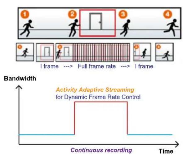

NOTE:
▶ To enable adaptive recording, please make sure you've set up the trigger source such as Motion Detection, DI Device, or Manual Trigger.
▶ When there is no alarm trigger:
- JPEG mode: record 1 frame per second.
- H.264 mode: record the I frame only.
- MPEG-4 mode: record the I frame only.
▶ When the I frame period is >1s on Video settings page, firmware will force decrease the I frame period to 1s when adaptive recording is enabled.
The alarm trigger includes: motion detection, tampering detection, and DI detection. Please refer to Event Settings on page 91.
■ Pre-event recording and post-event recording
The Network Camera has a buffer area (a flash memory); it temporarily holds data up to a certain limit. Enter a number to decide the duration of recording before and after a trigger is activated.
■ Priority: Select the relative importance of this recording (High, Normal, or Low). Recording with a higher priority setting will be executed first.
■ Source: Select a stream as the recording source.

NOTE:
▶ To enable recording notification please configure Event settings first. Please refer to page 91.
Please follow the steps below to set up the recording.
1. Trigger
Select a trigger source.
![Trigger Schedule Sun Mon Tue Wed Thu Fri Sat Time Always From 00:00 to 24:00 [hh:mm] Network fail](/content/2026/06/1186415/images/0c90fd216ad828ee01ccf658d304f8fe074ee2babcf71041e6e88bbc5b72d950.jpg)
■ Schedule: The server will start to record files on the local storage or a networked storage (NAS).
■ Network fail: Since network fail, the server will start to record files on the local storage (SD card).
2. Destination
You can select the SD card or network storage (NAS) for the recorded video files.
![Recording name: recording_Mylest Enable this recording With adaptive recording (Help) Priority: High Source: Stream 1 1. Trigger Destination: Destination: SD Recording file management Maximum duration: 1 minutes [1-60] Maximum file size: 108 MB [100-2000] File name prefix: recordingtest Add NAS server 2. Destination Note: To enable recording notification please configure Event first Save Close](/content/2026/06/1186415/images/44fc658fdc7bc40394fbb98415c747c5686bb80879afab237236aaf4de761535.jpg)
NAS server
If you have not configured a NAS server, click Add NAS server to open the server setting window and follow the steps below to set up:
- Fill in the information for your server.
For example:
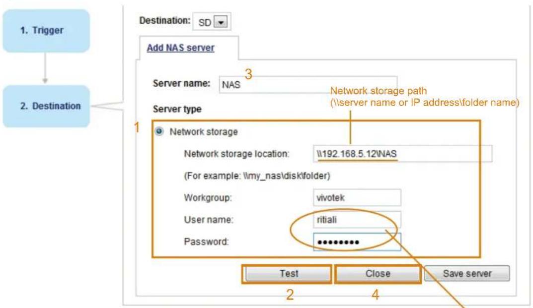
flowchart
graph TD
    A["1. Trigger"] --> B["2. Destination"]
    B --> C["Add NAS server"]
    C --> D["Server name: NAS"]
    D --> E["Server type"]
    E --> F["Network storage"]
    F --> G["Network storage location: \192.168.5.12NAS"]
    G --> H["(For example: \my_nas\disk\folder)"]
    H --> I["Workgroup: vivotek"]
    I --> J["User name: ritiali"]
    J --> K["Password: ********..."]
    K --> L["Test"]
    K --> M["Close"]
    K --> N["Save server"]
User name and password for your server
- Click Test to check the setting. The result will be shown in the pop-up window.
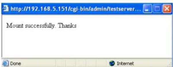
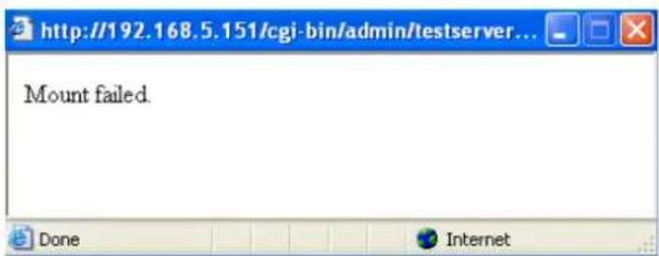
If successful, you will receive a test.txt file on the network storage server.
![NAS on ritali File Edit View Favorites Tools Help Back Search Folders Address \ritali\NAS File and Folder Tasks Rename this file Move this file Copy this file Publish this file to the Web E-mail this file Print this file Delete this file Other Places test.txt Text Document 1 KB test.txt - Notepad File Edit Format View Help [NOTIFICATION]The Result of Server Test of Your IP Camera](/content/2026/06/1186415/images/21fbcde22ca05bcc5915e7db04164b3c7bc76781d2d3573ba3ca985aeed04c42.jpg)

NOTE:
To edit or remove an existing NAS setting, you have to turn OFF all related event or recording configurations.
- Enter a server name.
- Click Save to complete the settings and click Close to exit the page.
Back to the Recording setup page, you can now record videos to the networked storage.
![Recording name: recording_first Enable this recording With adaptive recording (Help) Priority: High Source: Stream 1 Destination Destination: NAS Capacity: Extra tree space Reserved space: 100 Mbytes Enable cyclic recording Recording file management Maximum duration: 1 minutes [1-50] Maximum file size: 10 MB [100-2000] File name prefix: recordingtest 1. Trigger 2. Destination Note: To enable recording notification please configure Event first Save Close](/content/2026/06/1186415/images/677f28e6a3e3f165a4cebad571d49e5fa387867d1f8dc5991ff6ae0f4efee638.jpg)
■ Capacity: You can choose either the entire free space available or limit the reserved space. The recording size limit must be larger than the reserved amount for cyclic recording.
■ File name prefix: Enter the text that will be appended to the front of the file name.
■ Enable cyclic recording: If you check this item, when the maximum capacity is reached, the oldest file will be overwritten by the latest one. The reserved amount is reserved for the transaction stage when the storage space is about to be full and new data arrives. The minimum for the Reserved space must be larger than 15 MBytes.
Recording file management
■ Maximum duration (minutes): Specifies the length of each of the recorded videos.
■ Maximum file size: (MB - Megabytes): Specifies the file size limitation of each recorded video. The duration and size are the upper thresholds. The limitation is imposed when either the length or the file size is reached. The recording then continues by creating other video files.
■ File name prefix: You may enter a file name prefix for the recorded files.
If you want to enable recording notification, please click Event to configure event triggering settings. Please refer to Event > Event settings on page 91 for more details.
When completed, select Enable this recording. Click Save to enable the setting and click Close to exit this page. When the system begins recording, it will send the recorded files to the network storage. The new recording name will appear in the drop-down list on the recording page as shown below.
To remove a recording setting from the list, select a recording name from the drop-down list and click Delete. — Recording Settings
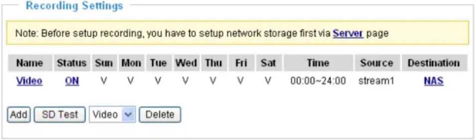
■ Click Video (Name): Opens the Recording Settings page to modify.
- Click ON (Status): The Status will become OFF and stop recording.
■ Click NAS (Destination): Opens the file list of recordings as shown below. For more information about folder naming rules, please refer to page 97 for details.
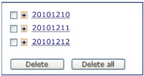
Local storage > SD card management Advanced Mode
This section explains how to manage the local storage on the Network Camera. Here you can view SD card status, and implement SD card control.
SD card staus
This column shows the status and reserved space of your SD card. Please remember to format the SD card when using for the first time.
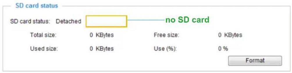
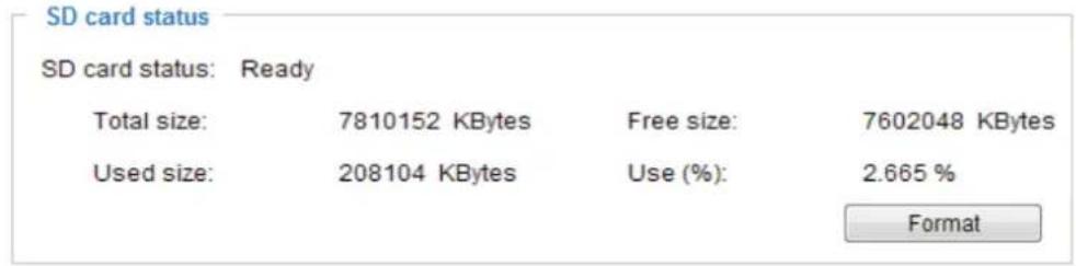
SD card control
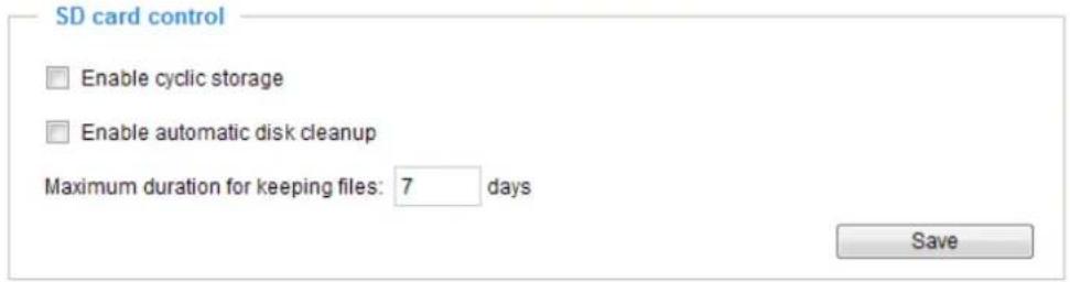
■ Enable cyclic storage: Check this item if you want to enable cyclic recording. When the maximum capacity is reached, the oldest file will be overwritten by the latest one.
■ Enable automatic disk cleanup: Check this item and enter the number of days you wish to retain a file. For example, if you enter "7 days", the recorded files will be stored on the SD card for 7 days.
Click Save to enable your settings.
Local storage > Content management
Advanced Mode
This section explains how to manage the content of recorded videos on the Network Camera. Here you can search and view the records and view the searched results.
Searching and Viewing the Records
This column allows the user to set up search criteria for recorded data. If you do not select any criteria and click Search button, all recorded data will be listed in the Search Results column.
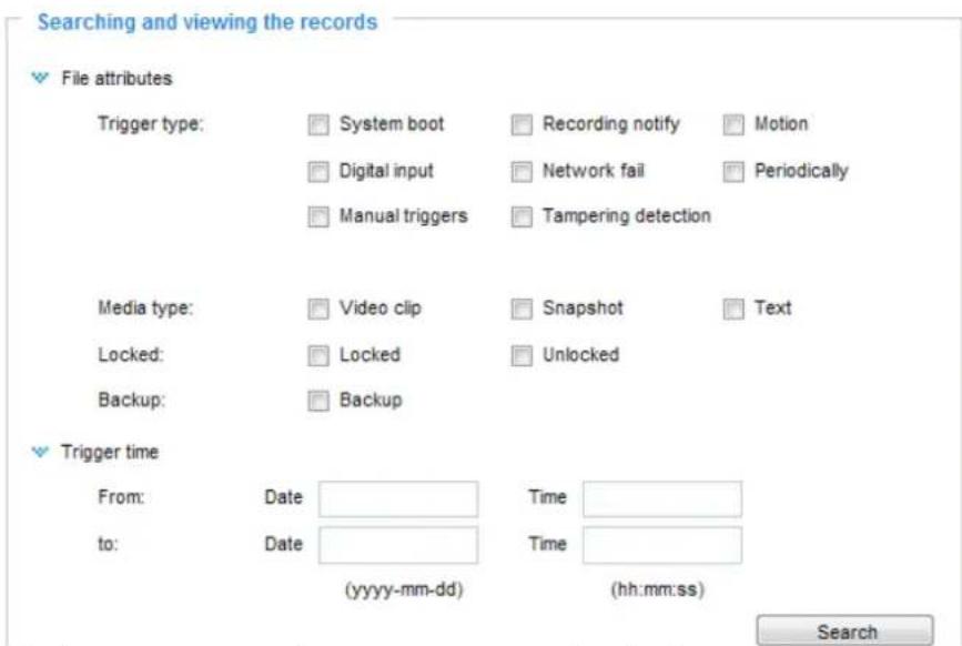
■ File attributes: Select one or more items as your search criteria.
■ Trigger time: Manually enter the time range you want to search.
Click Search and the recorded data corresponding to the search criteria will be listed in Search Results window.
Search Results
The following is an example of search results. There are four columns: Trigger time, Media type, Trigger type, and Locked. Click to sort the search results in either direction.
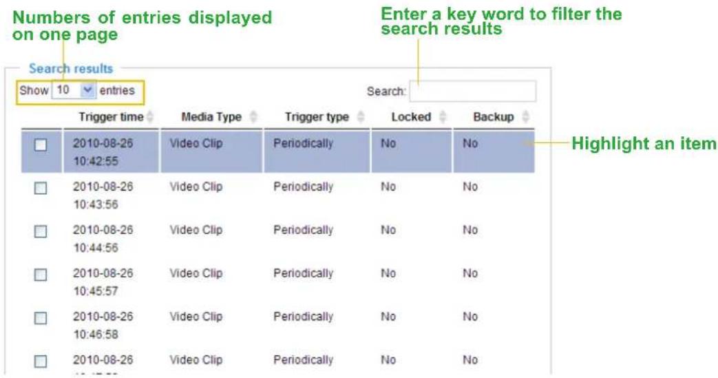
■ View: Click on a search result which will highlight the selected item in purple as shown above. Click the View button and a media window will pop up to play back the selected file.
For example:
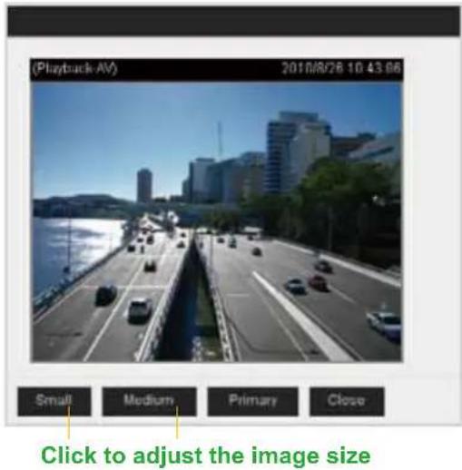
■ Download: Click on a search result to highlight the selected item in purple as shown above. Then click the Download button and a file download window will pop up for you to save the file.
■ JPEGs to AVI: This functions only applies to "JPEG" format files such as snapshots. You can select several snapshots from the list, then click this button. Those snapshots will be converted into an AVI file.
■ Lock/Unlock: Select the desired search results, then click this button. The selected items will become Locked, which will not be deleted during cyclic recording. You can click again to unlock the selections. For example:
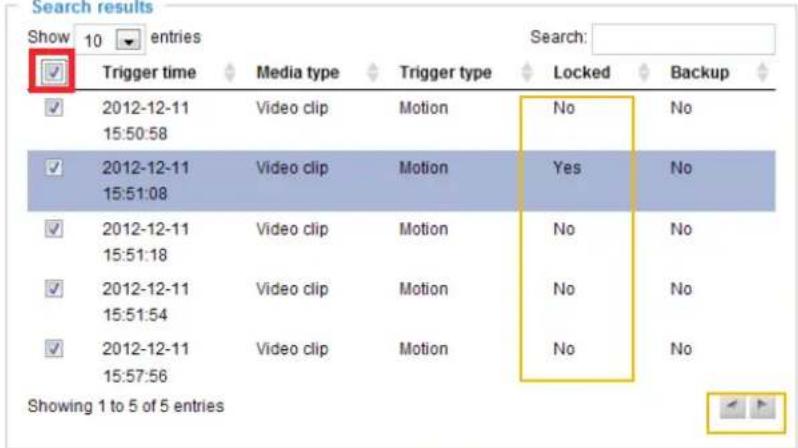
Click to switch pages

■ Remove: Select the desired search results, then click this button to delete the files.
Appendix
URL Commands for the Network Camera
1. Overview
For some customers who already have their own web site or web control application, the Network Camera/Video Server can be easily integrated through URL syntax. This section specifies the external HTTP-based application programming interface. The HTTP-based camera interface provides the functionality to request a single image, control camera functions (PTZ, output relay etc.), and get and set internal parameter values. The image and CGI-requests are handled by the built-in Web server.
2. Style Convention
In URL syntax and in descriptions of CGI parameters, text within angle brackets denotes content that is to be replaced with either a value or a string. When replacing the text string, the angle brackets should also be replaced. An example of this is the description of the name for the server, denoted with
URL syntax is denoted with the word "Syntax:" written in bold face followed by a box with the referenced syntax as shown below. For example, name of the server is written as
Syntax:
http://
Description of returned data is written with "Return:" in bold face followed by the returned data in a box. All data is returned in HTTP format, i.e., each line is separated with a Carriage Return and Line Feed (CRLF) printed as \n.
Return:
HTTP/1.0
URL syntax examples are written with "Example:" in bold face followed by a short description and a light grey box with the example.
Example: request a single snapshot image
http://mywebserver/cgi-bin/viewer/video.jpg
3. General CGI URL Syntax and Parameters
When the CGI request includes internal camera parameters, these parameters must be written exactly as they are named in the camera or video server. The CGIs are organized in functionally-related directories under the cgi-bin directory. The file extension .cgi is required.
Syntax:
http://<servername>/cgi-bin/<subdir>[/<subdir>...]/<cgi>.<ext>[?<parameter><value>[&<parameter><value>...]]
Example: Set digital output #1 to active
http://mywebserver/cgi-bin/dido/setdo.cgi?do1=1
4. Security Level
| SECURITY LEVEL | SUB-DIRECTORY DESCRIPTION | |
| 0 anonymous | Unprotected. | |
| 1 [view] anonymous, viewer, dido, camctrl | 1. Can view, listen, talk to camera.2. Can control DI/DO, PTZ of the camera. | |
| 4 [operator] anonymous, viewer, dido, camctrl, operator | Operator access rights can modify most of the camera's parameters except some privileges and network options. | |
| 6 [admin] anonymous, viewer, dido, camctrl, operator, admin | Administrator access rights can fully control the camera's operations. | |
| 7 N/A Internal parameters. Unable to be changed by any external interfaces. | ||
5. Get Server Parameter Values
Note: The access right depends on the URL directory.
Method: GET/POST
Syntax:
http://<servername>/cgi-bin/anonymous/getparam.cgi?[<parameter>]
[&<parameter>...]

http://<servername>/cgi-bin/viewer/getparam.cgi?[<parameter>]
[&<parameter>...]

http://<servername>/cgi-bin/operator/getparam.cgi?[<parameter>]
[&<parameter>...]

http://<servername>/cgi-bin/admin/getparam.cgi?[<parameter>]
[&<parameter>...]
Where the
When querying parameter values, the current parameter values are returned.
A successful control request returns parameter pairs as follows:
Return:
HTTP/1.0 200 OK\r\n
Content-Type: text/html\r\n
Context-Length: <length>\r\n
\r\n
<parameter pair>
where <parameter pair> is
<parameter>=<value>\r\n
[<parameter pair>]
Example: Request IP address and its response
Request:
http://192.168.0.123/cgi-bin/admin/getparam.cgi?network_ipaddress
Response:
HTTP/1.0 200 OK\r\n
Content-Type: text/html\r\n
Context-Length: 33\r\n
\r\n
network_ipaddress=192.168.0.123\r\n
6. Set Server Parameter Values
Note: The access right depends on the URL directory.
Method: GET/POST
Syntax:
http://<servername>/cgi-bin/anonymous/setparam.cgi? <parameter>=<value>
[&<parameter>=<value>...][&return=<return page]

http://<servername>/cgi-bin/viewer/setparam.cgi? <parameter>=<value>
[&<parameter>=<value>...][&return=<return page]

http://<servername>/cgi-bin/operator/setparam.cgi? <parameter>=<value>
[&<parameter>=<value>...][&return=<return page]

http://<servername>/cgi-bin/admin/setparam.cgi? <parameter>=<value>
[&<parameter>=<value>...][&return=<return page]
| PARAMETER VALUE DESCRIPTION | ||
| value to assigned | Assignto the parameter. | |
| return | Redirect to the pageafter the parameter is assigned. Thecan be a full URL path or relative path according to the current path. If you omit this parameter, it will redirect to an empty page.(Note: The return page can be a general HTML file (.htm, .html). It cannot be a CGI command or have any extra parameters. This parameter must be placed at the end of the parameter list | |
Return:
HTTP/1.0 200 OK\r\n
Content-Type: text/html\r\n
Context-Length: <length>\r\n
\r\n
<parameter pair>
where <parameter pair> is
<parameter>=<value>\r\n
[<parameter pair>]
Only the parameters that you set and are readable will be returned.
Example: Set the IP address of server to 192.168.0.123:
Request:
http://myserver/cgi-bin/admin/setparam.cgi?network_ipaddress=192.168.0.123
Response:
HTTP/1.0 200 OK\r\n
Content-Type: text/html\r\n
Context-Length: 33\r\n
\r\n
network_ipaddress=192.168.0.123\r\n
7. Available parameters on the server
This chapter defines all the parameters which can be configured or retrieved from VIVOTEK network camera or video server. The general format of description is listed in the table below
Valid values:
| VALID VALUES DESCRIPTION | |
| string[] | Text strings shorter than ‘n’ characters. The characters “,',<,>,& are invalid. |
| string[n~m] | Text strings longer than ‘n’ characters and shorter than ‘m’ characters. The characters “,',<,>,& are invalid. |
| password[] The same as string but displays ‘*’ instead. | |
| integer Any number between (-2 ^31 - 1) and ( 2^31 - 1). | |
| positive integer Any number between 0 and (2 ^32 - 1). | |
| ~Any number between ‘m’ and ‘n’. | |
| domain name[] A string limited to a domain name shorter than ‘n’ characters (eg. www.ibm.com). | |
| email address [] | A string limited to an email address shorter than ‘n’ characters (eg. joe@www.ibm.com). |
| ip address A string limited to an IP address (eg. 192.168.1.1). | |
| mac address A string limited to contain a MAC address without hyphens or colons. | |
| boolean A boolean value of 1 or 0 represents [Yes or No], [True or False], [Enable or Disable]. | |
| ,,,,,,... | Enumeration. Only given values are valid. |
| blank | A blank string. |
| everything inside <> | A description |
| integer primary key | SQLite data type. A 32-bit signed integer. The value is assigned a unique integer by the server. |
| text | SQLite data type. The value is a text string, stored using the database encoding (UTF-8, UTF-16BE or UTF-16-LE). |
| coordinate | x, y coordinate (eg. 0,0) |
| window size | window width and height (eg. 800x600) |
NOTE: The camera should not be restarted when parameters are changed.
7.1 system
Group: system
| NAME VALUE | DEFAULT SECURITY | (get/set) | DESCRIPTION | |
| hostname | string[64] | Mega-Pixel Network Camera | 1/6 Host name of server | |
| ledoff | 0 6/6 Turn on (0) or turn off (1) all led | indicators. | ||
| date | 6/6 | Current date of system. Set to‘keep’ to keep date unchanged.Set to ‘auto’ to use NTP to synchronize date. | ||
| time | 6/6 | Current time of the system. Set to‘keep’ to keep time unchanged.Set to ‘auto’ to use NTP to synchronize time. | ||
| datetime | 6/6 | Another current time format of the system. | ||
| ntp | 6/6 NTP server. | *Do not use “skip to invoke default server” for default value. | ||
| timezoneindex | -489 ~ 529 | 320 | 6/6 | Indicate timezone and area.-480: GMT-12:00 Eniwetok,Kwajalein-440: GMT-11:00 Midway Island,Samoa-400: GMT-10:00 Hawaii-360: GMT-09:00 Alaska-320: GMT-08:00 Las Vegas,San_Francisco,Vancouver-280: GMT-07:00 Mountain Time, Denver-281: GMT-07:00 Arizona-240: GMT-06:00 CentralAmerica, Central Time, Mexico City, Saskatchewan-200: GMT-05:00 Eastern Time, New York, Toronto-201: GMT-05:00 Bogota, Lima, Quito, Indiana-180: GMT-04:30 Caracas-160: GMT-04:00 Atlantic Time, Canada, La Paz, Santiago-140: GMT-03:30 Newfoundland-120: GMT-03:00 Brasilia, Buenos Aires, Georgetown, Greenland-80: GMT-02:00 Mid-Atlantic-40: GMT-01:00 Azores, Cape Verde IS.0: GMT Casablanca, Greenwich Mean Time: Dublin, Edinburgh, Lisbon, London40: GMT 01:00 Amsterdam, Berlin, Rome, Stockholm, Vienna, Madrid, Paris41: GMT 01:00 Warsaw, Budapest, Bern80: GMT 02:00 Athens, Helsinki, Istanbul, Riga81: GMT 02:00 Cairo82: GMT 02:00 Lebanon83: GMT 02:00 Israel120: GMT 03:00 Baghdad, Kuwait, Riyadh, St. Petersburg, Nairobi121: GMT 03:00 Iraq, Minsk140: GMT 03:30 Tehran160: GMT 04:00 Abu Dhabi, Moscow, Muscat, Baku, Tbilisi, Yerevan180: GMT 04:30 Kabul200: GMT 05:00 Ekaterinburg, |
| Islamabad, Karachi, Tashkent220: GMT 05:30 Calcutta,Chennai, Mumbai, New Delhi230: GMT 05:45 Kathmandu240: GMT 06:00 Almaty,Novosibirsk, Astana, Dhaka, SriJayawardenepura260: GMT 06:30 Rangoon280: GMT 07:00 Bangkok,Hanoi, Jakarta, Krasnoyarsk320: GMT 08:00 Beijing,Chongging, Hong Kong, KualaLumpur, Singapore, Taipei360: GMT 09:00 Osaka, Sapporo,Tokyo, Seoul, Yakutsk380: GMT 09:30 Adelaide,Darwin400: GMT 10:00 Brisbane,Canberra, Melbourne, Sydney,Guam, Vladivostok440: GMT 11:00 Magadan,Solomon Is., New Calcdonia480: GMT 12:00 Auckland,Wellington, Fiji, Kamchatka,Marshall Is.520: GMT 13:00 Nuku'Alofa | ||||
| daylight_enable | <boolean> 0 6/6 | Enable automatic daylight saving | time in time zone. | |
| daylight_auto_begintime | string[19] NONE | 6/7 Display the current daylight | saving start time. | |
| daylight_auto_endtime | string[19] NONE | 6/7 Display the current daylight | saving end time. | |
| daylight_timezones | string | -360,-320,-280,-240,-241,-200,-201,-160,-140,-120,-80,-40,0,40,41,80, | 6/6 List time zone index whichsupport daylight saving time. | |
| 81,82,83,120,140,380,400,480 | ||||
| updateinterval | 0,3600,86400,604800,2592000 | 0 6/6 0 to Disable automatic time | adjustment, otherwise, it indicates the seconds between NTP automatic update intervals. | |
| restore | 0,<positive integer> | N/A 7/6 Restore the system parameters to default values afterseconds. | ||
| reset | -1,0,<positive integer> | N/A 7/6 Restart the server afterseconds ifis non-negative. | ||
| restoreexceptnet | 0,<positive integer> | N/A 7/6 Restore the system parameters to default values except (ipaddress, subnet, router, dns1, dns2, pppoc).This command can cooperate with other “restoreexceptXYZ” commands. When cooperating with others, the system parameters will be restored to the default value except for a union of the combined results. | ||
| restoreexceptdst | 0,<positive integer> | N/A 7/6 Restore the system parameters to default values except all daylight saving time settings.This command can cooperate with other “restoreexceptXYZ” commands. When cooperating with others, the system parameters will be restored to default values except for a union of combined results. | ||
| restoreexceptlang | 0, | N/A 7/6 Restore the system parameters to default values except the custom language file the user has uploaded.This command can cooperate with other “restoreexceptXYZ” commands. When cooperating with others, the system parameters will be restored to the default value except for a union of the combined results. | ||
7.1.1 system.info
Subgroup of system: info (The fields in this group are unchangeable.)
| NAME VALUE DEFAULT | SECURITY | (get/set) | DESCRIPTION | |
| modelname string[40] FD8166 | 0/7 | Internal model name of the server (eg. FD8166) | ||
| serialnumber | 0/7 12 characters MAC address (without hyphens). | |||
| firmwareversion string[40] | product dependent> | 0/7 Firmware version, including model, company, and version number in the format: | ||
| language_count | 9 | 0/7 | Number of webpage languages available on the server. | |
| language_i<0~(count-1)> | string[16] | 0/7 Available language lists. | ||
| customlanguage_maxcount | 1 | 0/6 | Maximum number of custom languages supported on the server. | |
| customlanguage_count | 0 | 0/6 | Number of custom languages which have been uploaded to the server. | |
| customlanguage_i<0~(max count-1)> | string | 0/6 Custom language name. |
7.2 status
Group: status
| NAME VALUE DEFAULT SECURITY | (get/set) | DESCRIPTION | ||
| di_i<0~(ndi-1)>0 1/7 0 => Inactive, normal | 1 => Active, triggered (capability.ndi > 0) | |||
| onlinenum_rtsp integer 0 6/7 Current number of | RTSP connections. | |||
| onlinenum_httppush integer 0 6/7 Current number of | HTTP push server connections. | |||
| eth_i0 <string> <blank> | 1/7 Get network | information from mii-tool. | ||
| vi_i<0~(nvi-1)> <boolean> 0 1/7 Virtual input | 0 => Inactive1 => Active(capability.nvi > 0) |
7.3 digital input behavior define
Group: di_i<0\~(ndi-1)>
| NAME | VALUE | DEFAULT | SECURITY (get/set) | DESCRIPTION |
| normalstate | high, low | high | 1/1 | Indicates open circuit or closed circuit (inactive status) |
7.4 security
Group: security
| NAME VALUE DEFAULT SECURITY | (get/set) | DESCRIPTION | |
| privilege_camctrl view, operator, admin | view 1/6 Indicate which privileges and above can control PTZ (capability.ptzenabled >0 or capability.cptz >0) | ||
| user_i0_name string[64] root 6/7 User name of root | |||
| user_i<1~20>_name string[64] <blank> 6/7 | User name | ||
| user_i0_pass password[64] | 6/6 | Root password | |
| user_i<1~20>_pass password[64] | 7/6User password | 7/6 | User password |
| user_i0_privilege view, operator, admin | admin | 6/7 Root privilege | |
| user_i<1~20>_privilege view, operator, admin | 6/6User privilege | ||
7.5 network
Group: network
| NAME | VALUE | DEFAULT | SECURITY (get/set) | DESCRIPTION |
| preprocess | NULL | 6/6 | An 32-bit integer, each bit can be set separately as follows:Bit 0 => HTTP service;Bit 1=> HTTPS service;Bit 2=> FTP service;Bit 3 => Two way audio and RTSP Streaming service;To stop service before changing its port settings.It'srecommendedto set this parameter when change a service port to the port occupied by another service currently. Otherwise, the servicemay fail. Stopped service will auto-start after changing port settings. Ex: Change HTTP port from 80 to 5556, and change RTP port for video from 5556 to 20480. Then, set preprocess=9 to stop both service first. "/cgi-bin/admin/setparam.cgi? network_preprocess=9&network_http_port=5556 & network_rtp_videoport=20480" | |
| type | lan, pppoe | lan 6/6 Network connection type. | ||
| resetip1 6/61 => Get ipaddress, subnet, router, dns1, dns2 from DHCP server at next reboot. 0 => Use preset ipaddress, subnet, rounter, dns1, and dns2. | ||||
| ipaddress | 6/6 IP address of server. | |||
| subnet | Subnet mask. | |||
| router | Default gateway. | |||
| dns1 | Primary DNS server. | |||
| dns2 | Secondary DNS server. | |||
| wins1 | Primary WINS server. | |||
| wins2 | Secondary WINS server. | |||
7.5.1 802.1x
Subgroup of network: ieee8021x
| NAME VALUE DEF | AULT SECURITY | (get/set) | DESCRIPTION | |
| enable0 6/6 Enable/disable IEEE 802.1x | ||||
| eapmethod eap-peap, eap-tls eap-peap 6/6 | Selected EAP method | |||
| identity_peap string[64] | <blank> | 6/6 PEAP identity | ||
| identity_tls | string[64] | 6/6 | TLS identity | |
| password | string[253] | 6/6 | Password for TLS | |
| privatekeypassword | string[253] | 6/6 | Password for PEAP | |
| ca_exist | <boolean> 0 6/6 CA installed flag | |||
| ca_time | string[20] | 0 6/7 CA installed time. | Represented in EPOCH | |
| ca_size string[20] | 0 6/7 CA file size (in bytes) | |||
| certificate_exist | <boolean> | 0 | 6/6 | Certificate installed flag (for TLS) |
| certificate_time | string[20] | 0 6/7 Certificate installed time. | Represented in EPOCH | |
| certificate_size | string[20] | 0 6/7 Certificate file size (in bytes) | ||
| privatekey_exist | <boolean> 0 6/6 Private key installed flag | (for TLS) | ||
| privatekey_time | string[20] | 0 6/7 Private key installed time. | Represented in EPOCH | |
| privatekey_size | string[20] | 0 6/7 Private key file size (in bytes) | ||
7.5.2 QOS
Subgroup of network: qos_cos
| NAME | VALUE | DEFAULT | SECURITY (get/set) | DESCRIPTION |
| enable | 0 | 6/6 | Enable/disable CoS (IEEE 802.1p) | |
| vlanid | 1~4095 | 1 | 6/6 | VLAN ID |
| video | 0~7 | 0 | 6/6 | Video channel for CoS |
| audio | 0~7 | 0 | 6/6 | Audio channel for CoS (capability.naudio > 0) |
| eventalarm 0~7 0 | 6/6 Event/alarm channel for CoS | |||
| management | 0~7 | 0 | 6/6 | Management channel for CoS |
| eventtunnel 0~7 0 | 6/6 Event/Control channel for CoS | |||
Subgroup of network: qos_dscp
| NAME VALUE | DEFAULT SECURITY | (get/set) | DESCRIPTION | |
| enable | 0 | 6/6 | Enable/disable DSCP | |
| video | 0~63 | 0 | 6/6 | Video channel for DSCP |
| audio | 0~63 | 0 | 6/6 | Audio channel for DSCP(capability.naudio > 0) |
| eventalarm 0~63 0 | 6/6 | Event/alarm channel for DSCP | ||
| management | 0~63 | 0 | 6/6 | Management channel for DSCP |
| eventtunnel 0~63 0 | 6/6 | Event/Control channel for DSCP | ||
7.5.3 IPV6
Subgroup of network: ipv6
| NAME | VALUE | DEFAULT | SECURITY (get/set) | DESCRIPTION |
| enable | 0 | 6/6 | Enable IPv6. | |
| addonipaddress | 6/6 | IPv6 IP address. | ||
| addonprefixlen | 0~128 | 64 | 6/6 | IPv6 prefix length. |
| addonrouter | 6/6 | IPv6 router address. | ||
| addondns | 6/6 | IPv6 DNS address. | ||
| allowoptional | 0 | 6/6 | Allow manually setup of IP address setting. |
7.5.4 FTP
Subgroup of network: ftp
| NAME | VALUE | DEFAULT | SECURITY (get/set) | DESCRIPTION |
| port | 21, 1025~65535 | 21 | 6/6 | Local ftp server port. |
7.5.5 HTTP
Subgroup of network: http
| NAME VALUE DEF | AULT SECURITY | (get/set) | DESCRIPTION | |
| port | 80, 1025 ~ 65535 | 80 1/6 HTTP port. | ||
| alternateport 1025~65 | 535 8080 6/6 | Alternate HTTP port. | ||
| authmode | basic,digest | basic 1/6 HTTP authentication mode. | ||
| s0_accessname string | [32] video.mjpg | 1/6 HTTP server push access name for stream 1.(capability.protocol.spush_mjpeg=1 and capability.nmediastream >0) | ||
| s1_accessname | string[32] | video2.mjpg | 1/6 HTTP server push access name for stream 2.(capability.protocol.spush_mjpeg=1 and capability.nmediastream >1) | |
| s2_accessname | string[32] | videoany.mjpg | 1/6 Http server push access name for stream 3(capability.protocol.spush_mjpeg=1 and capability.nmediastream >2) | |
| anonymousviewing | 0 | 1/6 | Enable anonymous streaming viewing. | |
7.5.6 HTTPS port
Subgroup of network: https_port
| NAME | VALUE | DEFAULT | SECURITY (get/set) | DESCRIPTION |
| port | 443, 1025 ~ 65535 | 443 | 1/6 | HTTPS port. |
7.5.7 RTSP
Subgroup of network: rtsp
| NAME VALUE DEFAULT SECURITY | (get/set) | DESCRIPTION | |
| port 554, 1025~ | 65535 | 554 1/6 RTSP port. | (capability.protocol.rtsp=1) |
| anonymousviewing | 0 | Enable anonymous streaming viewing. | |
| authmode | disable, basic, digest | disable 1/6 RTSP authentication mode. | (capability.protocol.rtsp=1) |
| s0_accessname string[3] | live.sdp 1/6 RTSP access name for stream1. | capability.protocol.rtsp=1 and capability.nmediastream >0) | |
| s1_accessname string[3] | live2.sdp 1/6 RTSP access name for stream2. | (capability.protocol.rtsp=1 and capability.nmediastream >1) | |
| s2_accessname string[3] | liveany.sdp 1/6 RTSP access name for stream3 | (capability.protocol.rtsp=1 and capability.nmediastream >2) | |
7.5.7.1 RTSP multicast
Subgroup of network_rtsp_s<0\~(n-1)>: multicast, n is stream count
| NAME | VALUE | DEFAULT | SECURITY (get/set) | DESCRIPTION |
| alwaysmulticast | 0 | 4/4 | Enable always multicast. | |
| ipaddress | For n=0, 239.128.1.99 For n=1, 239.128.1.100, and so on. | 4/4 | Multicast IP address. | |
| videoport | 1025 ~ 65535 | 5560+n*2 | 4/4 | Multicast video port. |
| audiport | 1025 ~ 65535 | 5562+n*2 | 4/4 | Multicast audio port. (capability.naudio >0) |
| ttl 1~255 15 4/4 | Mutlicast time to live value. |
7.5.8 RTP port
Subgroup of network: rtp
| NAME VALUE DEFAULT SECURITY | (get/set) | DESCRIPTION | ||
| videoport 1025 ~ 65535 5556 6/6 | Video channel port for RTP. | |||
| audiport 1025 ~ 65535 5558 6/6 | Audio channel port for RTP. | |||
7.5.9 PPPoE
Subgroup of network: pppoe (capability.protocol.pppoe > 0)
| NAME | VALUE | DEFAULT | SECURITY (get/set) | DESCRIPTION |
| user | string[128] | 6/6 | PPPoE account user name. | |
| pass | password[64] | 6/6 | PPPoE account password. |
7.6 ipfilter
Group: ipfilter
| NAME | VALUE | DEFAULT | SECURITY (get/set) | DESCRIPTION |
| enable | 0 | 6/6 | Enable access list filtering. | |
| admin_enable | 0 | 6/6 | Enable administrator IP address. | |
| admin_ip | string[43] | 6/6 | Administrator IP address. | |
| maxconnection | 0~10 | 10 | 6/6 | Maximum number of concurrent streaming connection(s). |
| type | 0, 1 | 1 | 6/6 Ipfilter policy :0 => allow1 => deny | |
| ipv4list_i<0~9> | Single address:Network | 6/6 IPv4 address list. | ||
| address: | ||||
| address /network mask>Rangeaddress:<start ipaddress - end ipaddress> | ||||
| ipv6list_i<0~9> string[43] | 6/6 IPv6 address list. | |||
7.7 video input
Group: videooin
| NAME VALUE DEFAULT SECURITY | (get/set) | DESCRIPTION | |
| cmosfreq 50, 60 60 4/4 CMOS frequency. | (capability.videoin.type=2) | ||
| whitebalance auto, manual, rbgain | auto 4/4 “auto” indicates auto white balance. “manual” indicates keep current value. “rbgain” indicates using rgain and gbain. | ||
| exposurelevel 0~12 6 | 4/4 Exposure level | ||
| enableblc | 0 | 4/4 Enable backlight compensation. | |
7.7.1 video input setting per channel
Group: videoin_c<0\~(n-1)> for n channel products, and m is stream number
| NAME | VALUE | DEFAULT | SECURITY (get/set) | DESCRIPTION |
| cmosfreq | 50, 60 | 60 | 4/4 | CMOS frequency. (capability.videoin.type=2) |
| whitebalance | auto, manual, rbgain | auto 4/4 “auto” indicates auto | auto white balance. “manual” indicates keep current value. “rbgain” indicates using rgain and gbain. | |
| rgain 0~100 30 4/4 Manual set rgain value of | gain control setting. | |||
| bgain 0~100 30 4/4 Manual set bgain value of | gain control setting. | |||
| exposurelevel 0~12 6 4/4 Exposure level | ||||
| maxgain 0~100 100 4/4 Manual set maximum gain | value. | |||
| mingain 0~100 0 4/4 Manual set minimum gain | value. | |||
| color 0, 1 1 | 4/4 0 => monochrome | 1 => color | ||
| flip | 0 | 4/4 | Flip the image. | |
| mirror | 0 | 4/4 | Mirror the image. | |
| ptzstatus | 2 | 1/7 | A 32-bit integer, each bit can be set separately as follows: Bit 0 => Support camera control function; 0 (not support), 1 (support) Bit 1 =>Built-in or external camera; 0 (external), 1 (built-in) Bit 2 => Support pan operation; 0 (not support), 1 (support) Bit 3 => Support tilt operation; 0 (not support), 1 (support) Bit 4 => Support zoom operation; 0 (not support), 1 (support) Bit 5 => Support focus operation; 0 (not support),1(support) | |
| text string[40]1/4 Enclose caption. | ||||
| imprinttimestamp0 4/4 Overlay time stamp on | video. | |||
| flickerless0 4/4 Enable flickerless mode or | not.Enable flickerless mode will limit the parameters:minexposure and maxexposure between 5~120. | |||
| minexposure 5,15,25,30,50,6 | 0,100,120,240,250,480,500,1000,2000,4000,8000,16000,32000 | 32000 4/4 | Minimum exposure time. | |
| maxexposure | 5,15,25,30,50,60,100,120,240,250,480,500,1000,2000,4000,8000,16000,32000 | 30 4/4 | Maximum exposure time. | |
| enableblc 0~1 0 4/4 Enable backlight | compensation | |||
| s<0~(m-1>_codectype | mjpeg, h264 | h264 | 1/4 | Video codec type.svc is only supported with stream 0. |
| s<0~(m-1>_resolution | "176~1920"x"144~1080" | 1920x1080 | 1/4 Video resolution in pixels. | |
| s<0~(m-1>_h264_intraperiod | 250, 500,1000, 2000,3000, 4000 | 1000 | 4/4 | Intra frame period in milliseconds. |
| s<0~(m-1)>_h264_priority policy | framerate, imagequality | framerate 4/4 | The policy | to apply when the target bit rate is not sufficient to satisfy current encoded conditions. “framerate” indicates frame rate first. “imagequality” indicates image quality first. |
| s<0~(m-1)>_h264_ratecontrolmode | cbr, vbr cbr 4/4 | cbr, constant bitrate | vbr, fix quality | |
| s<0~(m-1)>_h264_quant | 1~5,99,100 | 3 4/4 Quality of video when choosing vbr in “ratecontrolmode”. 99,100 is the customized manual input setting. 1 = worst quality, 5 = best quality. | ||
| s<0~(m-1)>_h264_qpercent | 1~100 45 | 4/4 Set quality by percentage. | 1: Worst quality 100: Best quality (s<0~(m-1)>_h264_quant = 100) | |
| s<0~(m-1)>_h264_qvalue | 0~51 | 29 | 4/4 Manual video quality level input. (s<0~(m-1)>_h264_quant = 99) | |
| s<0~(m-1)>_h264_bitrate 1000 | ~8000000 3000000 | 4/4 Set bit rate in bps when choosing cbr in “ratecontrolmode”. | ||
| s<0~(m-1)>_h264_maxvbrbitrate | 1000~4000000 0 | 40000000 | 4/4 Maximum vbr bitrate | |
| s<0~(m-1)>_h264_maxframe | 1~25, 26~30 (only for 60Hz CMOS) | 15 1/4 Set maximum frame | rate in fps (for h264). | |
| s<0~(m-1)>_h264_profile | 0~2 | 1 | 1/4 | Indicate H264 profiles 0: baseline 1: main profile 2: high profile |
| s<0~(m-1)>_mjpeg_priority policy | framerate, imagequality | framerate 4/4 | The policy to | apply when the target bit rate is not sufficient to satisfy current encoded conditions. “framerate” indicates frame rate first. “imagequality” indicates image quality first. |
| s<0~(m-1)>_mjpeg_rate controlmode | cbr, vbr cbr 4/4 | cbr, constant | bitrate | vbr, fix quality |
| s<0~(m-1)>_mjpeg_quant 1 ~ 599, 100 | 3 4/4 | Quality of video when | choosing vbr in “ratecontrolmode”.99,100 is the customized manual input setting.1 = worst quality, 5 = best quality. | |
| s<0~(m-1)>_mjpeg_maxframe | 1~25,26~30 (only for 60Hz CMOS) | 30 1/4 Set maximum frame | rate in fps (for JPEG). | |
| s<0~(m-1)>_mjpeg_qvalue | 10~200 | 49 4/4 Manual video quality | level input.(s<0~(m-1)>_mjpeg_quant = 99) | |
| s<0~(m-1)>_mjpeg_qpercent | 1~100 49 | 4/4 Set quality | by percentage. | 1: Worst quality100: Best quality(s<0~(m-1)>_mjpeg_quant = 100) |
| s<0~(m-1)>_mjpeg_bitrate 1 | 000~8000000 | 6000000 | 4/4 Set bit rate | in bps when choosing cbr in “ratecontrolmode”. |
| s<0~(m-1)>_mjpeg_maxvbrbitrate | 1000~40000000 | 40000000 | 4/4 Maximum | vbr bitrate |
| s<0~(m-1)>_forcei 1 | NULL | 7/6 Force I | frame. | |
7.7.1.1 Alternative video input profiles per channel
In addition to the primary setting of video input, there can be alternative profile video input setting for each channel which might be for different scene of light (daytime or nighttime).
Group: videoin_c<0\~(n-1)>_profile_i<0\~(m-1)>
| NAME VALUE DEFAULT SECURITY | (get/set) | DESCRIPTION | ||
| enable0 4/4 Enable/disable this profile setting | ||||
| policy schedule schedule 4/4 The mode which the profile is applied to. | ||||
| begintime hh:mm 18:00 4/4 Begin time of schedule mode. | ||||
| endtime | hh:mm 06:00 | 4/4 End time of schedule mode. | ||
| flickerless | 0 4/4 Enable flickerless mode or not. | Enable flickerless mode will limit the parameters: minexposure and maxexposure between 5~120. | ||
| minexposure | 5,15,25,30,50,60,100,120,240,250,480,500,1000,2000,4000,8000,16000,32000 | 32000 | 4/4 Minimum | exposure time. |
| maxexposure | 5,15,25,30,50,60,100,120,240,250,480,500,1000,2000,4000,8000,16000,32000 | 30 | 4/4 Maximum | exposure time. |
| exposurelevel | 0~12 | 6 4/4 Exposure level | ||
| maxgain | 0~100 | 100 | 4/4 | Manual set maximum gain value. |
| mingain | 0~100 | 0 4/4 Manual set minimum gain value. | ||
| enableble | 0 4/4 Enable backlight compensation. | |||
| whitebalance | auto,manual,rbgain | auto | 4/4 | “auto” indicates auto white balance.“manual” indicates keepcurrent value.“rbgain” indicates using rgain |
| rgain 0~100 30 4/4 | Manual set rgain | value of gain | control setting. | |
| bgain 0~100 30 4/4 | Manual set bgain | value of gain | control setting. | |
7.8 video input preview
The temporary settings for video preview
Group: videoinpreview
| NAME VALUE DEFAULT SECURITY | (get/set) | DESCRIPTION | ||
| enableblc0 4/4 Preview of enable backlight | compensation. | |||
| minexposure | 5,15,25,30,50,60,100,120,240,250,480,500,1000,2000,4000,8000,16000,32000 | 32000 4/4 | Minimum exposure time. | |
| maxexposure | 5,15,25,30,50,60,100,120,240,250,480,500,1000,2000,4000,8000,16000,32000 | 30 4/4 | Maximum exposure time. | |
| exposurelevel | 0~12 | 6 | 4/4 | Preview of exposure level |
| maxgain | 0~100 100 | 4/4 | Manual set maximum gain value | |
| mingain | 0~100 0 | 4/4 | Manual set minimum gain value | |
7.9 image setting per channel
Group: image_c<0\~(n-1)> for n channel products
| NAME VALUE DE | FAULT SECURITY | (get/set) | DESCRIPTION | |
| brightness -5 ~ 5 -5 | 4/4 Adjust brightness of image according to mode settings. | |||
| saturation -5 ~ 5, 100 | 100 4/4 Adjust saturation of image according to mode settings.100 means using the parameter “saturationpercent”. | |||
| contrast -5 ~ 5 0 4/4 | Adjust contrast of image according to mode settings. | |||
| sharpness | -3 ~ 3, 100 | 100 | 4/4 | Adjust sharpness of image according to mode settings.100 means using the parameter “sharpnesspercent” |
| saturationpercent | 0 ~ 100 | 50 | 4/4 | Adjust saturation of image by percentage. Less 0 <-> 100 More saturation |
| sharpnesspercent | 0~100 | 50 | 4/4 | Adjust sharpness of image by percentage. Softer 0 <-> 100 Sharper |
| gammacurve | 0, 45 , 50,60, 70, 80,90, 100 | 0 | 4/4 Gamma curve. | |
| lowlightmode | 1 | 4/4 Enable/disable low light mode. | ||
| profile_i0_enable | 0 | 4/4 Enable/disable this profile setting | ||
| profile_i0_policy | schedule | schedule | 4/4 | The mode which the profile is applied to. |
| profile_i0_begintime | hh:mm | 18:00 | 4/4 Begin time of schedule mode. | |
| profile_i0_endtime | hh:mm | 06:00 | 4/4 | End time of schedule mode. |
| profile_i0_brightness | -5 ~ 5 -5 4/4 | Adjust brightness of image according to mode settings. | ||
| profile_i0_saturation | -5~5,100 | 0 4/4 Adjust saturation of image according to mode settings.100 means using the parameter “saturationpercent”. | ||
| profile_i0_contrast | -5 ~ 5 0 4/4 Adjust contrast of image according to | |||
| mode settings. | ||||
| profile_i0_sharpness | -3~3,100 0 | 4/4 Adjust sharpness of image | according to mode settings.100 means using the parameter “sharpnesspercent” | |
| profile_i0_saturationpercent | 0~100 50 | 4/4 Adjust saturation of image | by percentage.Less 0 <-> 100 More saturation | |
| profile_i0_sharpnesspercent | 0~100 50 | 4/4 Adjust sharpness of image by percentage.Softer 0 <-> 100 Sharper | ||
| profile_i0_lowlightmode | 1 | 4/4 Enable/disable low light mode. | ||
| profile_i0_gammacurve | 0, 45, 50,60, 70, 80,90, 100 | 0 4/4 Gamma curve. | ||
7.11 image setting for preview
Group: imagepreview_c<0\~(n-1)> for n channel products
| NAME VALUE | DEFAULT SECURITY | (get/set) | DESCRIPTION | |
| brightness | -5 ~ 5 | -5 | 4/4 | Adjust brightness of image according to mode settings. |
| saturation | -5 ~ 5, 100 | 100 | 4/4 | Adjust saturation of image according to mode settings.100 means using the parameter “saturationpercent”. |
| contrast | -5 ~ 5 0 4/4 | Adjust contrast | of image according to mode settings. | |
| sharpness | -3 ~ 3, 100 | 100 | 4/4 | Adjust sharpness of image according to mode settings.100 means using the parameter “sharpnesspercent” |
| saturationpercent | 0 ~ 100 | 50 | 4/4 | Adjust saturation of image by percentage. Less 0 <-> 100 More saturation |
| sharpnesspercent | 0~100 | 50 | 4/4 | Adjust sharpness of image by percentage. Softer 0 <-> 100 Sharper |
| gammacurve | 0, 45 , 50,60, 70, 80,90, 100 | 0 | 4/4 Gamma curve. | |
| lowlightmode | 1 | 4/4 Enable/disable low light mode. |
7.12 Audio input per channel
Group: audioin_c<0\~(n-1)> for n channel products
| NAME VALUE DEF | AULT SECURITY | (get/set) | DESCRIPTION | |
| source | lincin, | lincin 4/4 micin => use | external microphoneinput.linein => use built-in microphoneinput. | |
| mute 0,1 | 0 | 1/4 Enable audio mute. | ||
| gain | 0~100 | 65 | 4/4 Gain of input.(audioin_c<0~(n-1)>_source = linein) | |
| s<0~(m-1)>_g711_mode | pcmu,pcma | pcmu | 4/4 Set G.711 | mode. |
7.13 Time Shift settings
Group: timeshift, c for n channel products, m is stream number
| NAME | VALUE | DEFAULT | SECURITY(get/set) | DESCRIPTION |
| enable | 0 | 4/4 | Enable time shift streaming. | |
| c<0~(n-1)>_s<0~(m-1)>_allow | 0 | 4/4 | Enable time shift streaming for specific stream. |
7.14 Motion detection settings
Group: motion_c<0\~(n-1)> for n channel product
| NAME | VALUE | DEFAULT | SECURITY (get/set) | DESCRIPTION |
| enable | 0 | 4/4 | Enable motion detection. | |
| win_i<0~2>_enable | 0 | 4/4 | Enable motion window 1~3. | |
| win_i<0~2>_name | string[14] | 4/4 | Name of motion window 1~3. | |
| win_i<0~2>_left 0 ~ 320 | 0 4/4 Left coordinate of window | position. | ||
| win_i<0~2>_top 0 ~ 240 | 0 4/4 Top coordinate of window | position. | ||
| win_i<0~2>_width 0 ~ 320 | 0 4/4 Width of motion detection | window. | ||
| win_i<0~2>_height 0 ~ 240 | 0 4/4 Height of motion detection | window. | ||
| win_i<0~2>_objsize 0 ~ 100 | 0 4/4 Percent of motion detection | window. | ||
| win_i<0~2>_sensitivity 0 ~ 100 | 0 4/4 Sensitivity of motion detection | window. | ||
Group: motion_c<0\~(n-1)> profile for m profile and n channel product
| NAME VALUE DEFAULT SECURITY | (get/set) | DESCRIPTION | ||
| i<0~(m-1)>_enable | 0 | 4/4 | Enable profile 1 ~ (m-1). | |
| i<0~(m-1)>_policy | schedule | schedule | 4/4 | The mode which the profile is applied to. |
| i<0~(m-1)>_begintime | hh:mm | 18:00 | 4/4 | Begin time of schedule mode. |
| i<0~(m-1)>_endtime | hh:mm | 06:00 | 4/4 | End time of schedule mode. |
| i<0~(m-1)>_win_i<0~2>_enable | 0 | 4/4 | Enable motion window. | |
| i<0~(m-1)>_win_i<0~2>_name | string[14] | 4/4 | Name of motion window. | |
| i<0~(m-1)>_win_i<0~2>_left | 0 ~ 320 | 0 | 4/4 | Left coordinate of window position. |
| i<0~(m-1)>_win_i<0~2>_top | 0 ~ 240 | 0 | 4/4 | Top coordinate of window position. |
| i<0~(m-1)>_win_i<0~2>_width | 0 ~ 320 | 0 | 4/4 | Width of motion detection window. |
| i<0~(m-1)>_win_i<0~2>_height | 0 ~ 240 | 0 | 4/4 | Height of motion detection window. |
| i<0~(m-1)>_win_i<0~2>_objsize | 0 ~ 100 | 0 | 4/4 | Percent of motion detection window. |
| i<0~(m-1)>_win_i<0~2>_sensitivity | 0 ~ 100 | 0 | 4/4 | Sensitivity ofmotion detection window. |
7.15 Tampering detection settings
Group: tampering_c<0\~(n-1)> for n channel product
| NAME VALUE | DEFAULT | T SECURITY | (get/set) | DESCRIPTION |
| enable0 4/4Enable or disable tamper detection. | ||||
| threshold 0~255 32 1/7Threshold of tamper detection. | ||||
| duration 10~600 10 4/4If tampering value exceeds the ‘threshold’ formore than ‘duration’ second(s), then tamperdetection is triggered. | ||||
7.16 DDNS
Group: ddns
| NAME | VALUE | DEFAULT | SECURITY (get/set) | DESCRIPTION |
| enable | 0 | 6/6 | Enable or disable the dynamic DNS. | |
| provider | Safe100, DyndnsDynamic, DyndnsCustom, DynInterfree, CustomSafe100, PeanutHull | DyndnsDynamic | 6/6 | Safe100 => safe100.netDyndnsDynamic => dyndns.org (dynamic)DyndnsCustom => dyndns.org (custom)DynInterfree =>dyn-interfree.itCustomSafe100 =>Custom server using safe100 methodPeanutHull => PeanutHull |
| 颁布name | string[128] | 6/6 | Your DDNS hostname. | |
| usernameemail | string[64] | 6/6 | Your user name or email to login to the DDNS service provider | |
| passwordkey | string[64] | 6/6 | Your password or key to login to the DDNS service provider. | |
| servername | string[128] | 6/6 | The server name for safe100.(This field only exists if the provider is customsafe100) |
7.16.1 Express link
Group:expresslink
| NAME VALUE DEFAULT SECURITY | (get/set) | DESCRIPTION | ||
| enable0 | 6/6 Enable or disable express link. | |||
| state | onlycheck, onlyoffline, checkonline, badnetwork | 6/6 | “onlycheck”: You have to input the host name of your camera and press "Register" button to register it. “onlyoffline”: Express link is active, you can now connect to this camera at expresslink_url. “checkonline”: Express link is not active. “badnetwork”: Express Link is not supported under this network environment. | |
| url string[63]6/6 The URL to connect to this camera by express link. | ||||
| setparamlevel | 0~2 | 0 | 6/6 | Show log of parameter setting. 0: disable 1: Show log of parameter setting set from external. 2. Show log of parameter setting set from external and internal. |
7.17 UPnP presentation
Group: upnppresentation
| NAME | VALUE | DEFAULT | SECURITY (get/set) | DESCRIPTION |
| enable | 1 | 6/6 | Enable or disable the UPnP presentation service. |
7.18 UPnP port forwarding
Group: upnpportforwarding
| NAME VALUE DEFAULT SECURITY | (get/set) | DESCRIPTION | ||
| enable0 | 6/6 Enable or disable the UPnP port | forwarding service. | ||
| upnpnatstatus 0~3 0 | 6/7 The status of UPnP port forwarding, | used internally.0 = OK, 1 = FAIL, 2 = no IGDrouter, 3 = no need for portforwarding | ||
7.19 System log
Group: syslog
| NAME | VALUE | DEFAULT | SECURITY (gct/set) | DESCRIPTION |
| enableremotelog | 0 | 6/6 | Enable remote log. | |
| serverip | 6/6 | Log server IP address. | ||
| serverport | 514, 1025~65535 | 514 | 6/6 | Server port used for log. |
| level | 0~7 | 6 | 6/6 | Levels used to distinguish the importance of the information:0: LOG_EMERG1: LOG_ALERT2: LOG_CRIT3: LOG_ERR4: LOG_WARNING5: LOG_NOTICE6: LOG_INFO7: LOG_DEBUG |
7.20 SNMP
Group: snmp
| NAME VALUE DEFAULT SECURITY | (get/set) | DESCRIPTION | ||
| v2 0~1 0 6/6 SNMP | v2 enabled. 0 for | disable, 1 | for enable | |
| v3 0~1 0 6/6 SNMP | v3 enabled. 0 for | disable, 1 | for enable | |
| secnamerw string[31] | Private 6/6 Read/write security name | |||
| secnamero string[31] | Public 6/6 Read only security name | |||
| authpwrw | string[8~128] | 6/6 | Read/write authentication password | |
| authpwro | string[8~128] | 6/6 | Read only authentication password | |
| authtyperw MD5,SHA | MD5 | 6/6 Read/write authentication type | ||
| authtypero MD5,SHA | MD5 | 6/6 Read only authentication type | ||
| encryptpwrw | string[8~128] | 6/6 | Read/write passwd | |
| encryptpwro | string[8~128] | 6/6 | Read only password | |
| encrypttyperw | DES | DES | 6/6 | Read/write encryption type |
| encrypttypero | DES | DES | 6/6 | Read only encryption type |
| rwcommunity | string[31] Private | 6/6 Read/write community | ||
| rocommunity | string[31] Public | 6/6 Ready only community | ||
7.21 Layout configurationGroup: layout
| NAME | VALUE | DEFAULT | SECURITY(get/set) | DESCRIPTION |
| logo_default | 1 | 1/6 | 0 => Custom logo1 => Default logo | |
| logo_link | string[64] | http://www.vivotek.com | 1/6 | Hyperlink of the logo |
| logo_powerbyvvtk_hidden | 0 | 1/6 | 0 => display the power byvivotek logo1 => hide the power by vivotek logo | |
| theme_option 1~4 1 1/6 1~3: One of the default themes. | 4: Custom definition. | |||
| theme_color_font string[7] #ffffff 1/6 Font color | ||||
| theme_color_configfont string[7] #ffffff 1/6 Font color of configuration | area. | |||
| theme_color_titlefont string[7] #098bd6 1/6 Font color of video title. | ||||
| theme_color_controlbackground | string[7] #56 | 5656 1/6 Background color | of control area. | |
| theme_color_configbackground | string[7] #323 | 232 1/6 Background color of configuration area. | ||
| theme_color_videobackground | string[7] | #565656 1/6 Background color of video area. | ||
| theme_color_case string[7] #323 | 232 1/6 Frame color | |||
| custombutton_manualtrigger_show | 1 1/6 Show or hide manual | trigger(VI) button in homepage0 -> Hidden1 -> Visible | ||
7.22 Privacy mask
Group: privacymask_c<0\~(n-1)> for n channel product
| NAME | VALUE | DEFAULT | SECURITY (get/set) | DESCRIPTION |
| enable | 0 | 4/4 | Enable privacy mask. | |
| win_i<0~4>_enable | 0 | 4/4 Enable privacy mask window. | ||
| win_i<0~4>_name | string[40] | 4/4 | Name of the privacy mask window. | |
| win_i<0~4>_left | 0 ~ 320/352 | 0 | 4/4 | Left coordinate of window position. |
| win_i<0~4>_top | 0 ~ 240/288 | 0 | 4/4 | Top coordinate of window position. |
| win_i<0~4>_width | 0 ~ 320/352 | 0 | 4/4 | Width of privacy mask window. |
| win_i<0~4>_height 0 | ~240/288 0 4/4 | Height of privacy mask | window. | |
7.23 Capability
Group: capability
| NAME VALUE | DEFAULT SECURITY | (get/set) | DESCRIPTION | |
| api_httpversion 020 | 0a 0200a 0/7 The HTTP API version. | |||
| bootuptime | 60 | 0/7 | Server bootup time. | |
| nir | 0, | 0 | 0/7 Number of | IR interfaces.(Recommend to use ir for built-in IR and extir for external IR) |
| npir | 0, | 0 | 0/7 Number of | PIRs. |
| ndi | 0, | 1 | 0/7 Number of | digital inputs. |
| nvi | 0, | 3 | 0/7 Number of | virtual inputs (manual trigger) |
| ndo | 0, | 0 | 0/7 Number of | digital outputs. |
| naudioin | 0, | 1 | 0/7 Number of | audio inputs. |
| naudioout | 0, | 0 | 0/7 Number of | audio outputs. |
| nvideoin | 1 | 0/7 | Number of video inputs. | |
| nvideoinprofile | 1 | 0/7 | Number of video input profiles. | |
| nmediastream | 2 | 0/7 | Number of media stream per channels. | |
| nvideosetting | 2 | 0/7 | Number of video settings per channel. | |
| naudiosetting | 1 | 0/7 | Number of audio settings per channel. | |
| nuart | 0, | 0 | 0/7 Number of | UART interfaces. |
| nmotion | 0, | 3 | 0/7 | Number of motion window. |
| nmotionprofile | 0, | 1 | 0/7 | Number of motion profiles. |
| ptzenabled 0,0 0/7 An32-bit integer, each bit can beset separately as follows:Bit 0 => Support camera control function;0(not support), 1(support)Bit 1 => Built-in or external video source;0(external), 1(built-in)Bit 2 => Support pan operation,0(not support), 1(support)Bit 3 => Support tilt operation;0(not support), 1(support)Bit 4 => Support zoom operation;0(not support), 1(support)Bit 5 => Support focus operation;0(not support), 1(support)Bit 6 => Support iris operation;0(not support), 1(support)Bit 7 => External or built-in PT;0(built-in), 1(external)Bit 8 => Invalidate bit 1 ~ 7;0(bit 1 ~ 7 are valid),1(bit 1 ~ 7 are invalid)Bit 9 => Reserved bit; Invalidate lens_pan, Lens_tilt, lens_zoon,lens_focus, len_iris.0(fields are valid),1(fields are invalid)Examples:PT8133: 0b1111SD8362: 0b111111VS8102: 0b10111101 | ||||
| windowless1 0/7 Indicate whether to supportwindowless plug-in. | ||||
| eptz 0,1 0/7 A 32-bit integer, each bit can beset separately as follows:Bit 0 => stream 1 supports ePTZ or not.Bit 1 => stream 2 supports ePTZ or not.The rest may be deduced by analogy | ||||
| npreset 0,20 0/7 Number of preset locations. | ||||
| protocol_https <boolean> 1 0/7 Indicate whether to support HTTPover SSL. | over SSL. | |||
| protocol_rtsp <boolean> 1 0/7 Indicate whether to support RTSP. | ||||
| protocol_sip <boolean> 0 0/7 Indicate whether to support SIP. | ||||
| protocol_maxconnection | 10 0/7 The maximum allowed simultaneous connections. | |||
| protocol_maxgen connection | 10 | 0/7 | The maximum general streaming connections . | |
| protocol_maxmeg aconnection | 10 0/7 The maximum megapixel streaming connections. | |||
| protocol_rtp_multicast_ scalable | 1 0/7 Indicate whether to support | scalable multicast. | ||
| protocol_rtp_multicast_backchannel | 0 0/7 Indicate whether to support | backchannel multicast. | ||
| protocol_rtp_tcp | 1 0/7 Indicate whether to support RTP | over TCP. | ||
| protocol_rtp_http | 1 0/7 Indicate whether to support RTP | over HTTP. | ||
| protocol_spush_m jpeg | 1 0/7 Indicate whether to support server | push MJPEG. | ||
| protocol_snmp | 1 0/7 Indicate whether to support | SNMP. | ||
| protocol_ipv6 <boolean> 1 0/7 Indicate whether to support IPv6. | ||||
| protocol_pppoc <boolean> 1 0/7 Indicate whether to support | PPPoE. | |||
| protocol_ieee8021x | <boolean> 1 0/7 Indicate whether to support | IEEE802.1x. | ||
| protocol_qos_cos <boolean> 1 0/7 Indicate whether to support CoS. | ||||
| protocol_qos_dscp | <boolean> 1 0/7 Indicate whether to support | QoS/DSCP. | ||
| protocol_ddns <boolean> 1 0/7 Indicate whether to support | DDNS. | |||
| videoin_type 0, 1, 2 2 0/7 0 => Interlaced CCD | 1 => Progressive CCD2 => CMOS | |||
| videoin_resolution | 176x144,384x216,640x360,1280x720,1360x768,1600x904,1920x1080 | 176x144,384x216,640x360,1280x720,1360x768,1600x904,1920x1080 | 0/7 Available resolutions list. | |
| videoin_nresolution | 7 7 0/7 Available resolutions list. | |||
| videoin_maxframerate | 30,30,30,30,15,15,15 | 30,30,30,30,15,15,15 | 0/7 Available maximum frame list. | |
| videoin_mjpeg_maxframerate | 30,30,30,30,15,15,15 | 30,30,30,30,15,15,15 | 0/7 Available maximum frame list. | |
| videoin_h264_maxframerate | 30,30,30,30,15,15,15 | 30,30,30,30,15,15,15 | 0/7 Available maximum frame list. | |
| videoin_streamodec | 6,6 | 6,6 | 0/7 | Available stream codectype (Bit 0 -> mpeg4, Bit 1 -> mjpeg, Bit 2 -> h264, Bit 3 -> svc). |
| videoin_fov | 1920x1080 1920x1080 | 0/7 Available crop size list. | ||
| videoin_codec | mjpeg, h264 | mjpeg, h264 | 0/7 Available codec list. | |
| timeshift | <boolean> 1 0/7 Indicate whether to support time | shift caching stream. | ||
| audio_aec | <boolean> 0 0/7 Indicate whether to support | |||
| acoustic echo cancellation. | ||||
| audio_mic1 0/7 Indicate whether to supportbuilt-in microphone input. | ||||
| audio_extmic0 0/7 Indicate whether to supportexternal microphone input. | ||||
| audio_lincin0 0/7 Indicate whether to supportexternal line input.(It will be replaced by audio_mic and audio_extmic.) | ||||
| audio_lineout0 0/7 Indicate whether to support lineoutput. | ||||
| audio_headphone out0 0/7 Indicate whether to supportheadphone output. | ||||
| audioin_codec g711 g711 0/7 Available codec list for audioinput. | ||||
| uart_httptunnel0 0/7 Indicate whether to support HTTPtunnel for UART transfer. | ||||
| camctrl_httptunnel0 0/7 The attribute indicates whethersending camera control commands through HTTP tunnel is supported.0: Not supported1: Supported | ||||
| camctrl_privilege1 0/7 Indicate whether to support“Manage Privilege” of PTZ control in the Security page.1: support both/cgi-bin/camctrl/camctrl.cgi and/cgi-bin/viewer/camctrl.cgi0: support only/cgi-bin/viewer/camctrl.cgi | ||||
| transmission_mode | Tx Tx 0/7 Indicate transmission mode of themachine: TX = server, Rx = receiver box, Both = DVR. | |||
| network_wire1 0/7 Indicate whether to supportEthernet. | ||||
| network_wireless0 0/7 Indicate whether to supportwireless. | ||||
| wireless_s802dot11b | 0 0/7 Indicate whether to support | support | wireless 802.11b+. | |
| wireless_s802dot11g | 0 0/7 Indicate whether to support | support | wireless 802.11g. | |
| wireless_encrypt_wcp | 0 0/7 Indicate whether to support | support | wireless WEP. | |
| wireless_encrypt_wpa | 0 0/7 Indicate whether to support | support | wireless WPA. | |
| wireless_encrypt_wpa2 | 0 0/7 Indicate whether to support | support | wireless WPA2. | |
| derivative_brand | 1 0/7 Indicate whether to support the | upgrade function for the derivative brand. For example, if the value is true, the VVTK product can be upgraded to VVXX. (TCVV<->TCXX is excepted) | ||
| evctrlchannel | 1 0/7 Indicate whether to support HTTP | tunnel for event/control transfer. | ||
| joystick | 1 0/7 Indicate whether to support | joystick control. | ||
| storage_dbenable d | 1 0/7 Media files are indexed in | database. | ||
| nanystream 0, | 1 0/7 number of any media stream per channel | channel | ||
| iva | 0 0/7 Indicate whether to support | Intelligent Video analysis | ||
| ir | 1 0/7 Indicate whether to support | built-in IR led. | ||
| extir | 0 0/7 Indicate whether to support | external IR led. | ||
| whitelight | 0 0/7 Indicate whether to support white | light led. | ||
| iris | 0 0/7 Indicate whether to support iris | control. | ||
| tampering | 1 0/7 Indicate whether to support | tampering detection. | ||
| temperature | 0 0/7 Indicate whether to support | temperature detection. | ||
| image_wdrc0 0/7 Indicate whether to supportWDRC | 0 0/7 Indicate whether to support | WDRC | ||
| image_iristypedciris 0/7 Indicate iris type. | ||||
| image_focusassist0 0/7 Indicate whether to support focus assist. | 0 0/7 Indicate whether to support focus assist. | |||
| localstorage_manageable1 0/7 Indicate whether manageablelocal storage is supported. | 1 0/7 Indicate whether manageable | |||
| localstorage_seamless0 0/7 Indicate whether seamlessrecording is supported. | 0 0/7 Indicate whether seamless | |||
| localstorage_modnum0,0 0/7 The maximum MOD connection numbers. | 0,0 0/7 The maximum MOD connection numbers. | |||
| adaptiverecording1 0/7 Indicate whether to supportadaptive recording. | 1 0/7 Indicate whether to support adaptive recording. | |||
| adaptivestreaming1 0/7 Indicate whether to supportadaptive streaming. | 1 0/7 Indicate whether to support adaptive streaming. | |||
7.24 Customized event script
Group: event_customtaskfile_i<0\~2>
| PARAMETER VALUE | DEFAULT SEC | URITY | (get/set) | DESCRIPTION |
| name | string[40] | 6/6 | Custom script identification of this entry. | |
| date | string[4~20] | 6/6 | Date of custom script. | |
| time | string[4~20] | 6/6 | Time of custom script. |
7.25 Event setting
Group: event_i<0\~2>
| PARAMETER | VALUE | DEFAULT | SECURITY (get/set) | DESCRIPTION |
| name | string[40] | 6/6 | Identification of this entry. | |
| enable | 0, 1 | 0 | 6/6 | Enable or disable this event. |
| priority | 0, 1, 2 | 1 | 6/6 | Indicate the priority of this event: “0” = low priority“1” = normal priority“2” = high priority |
| delay 1~999 20 6/6 Delay in seconds before | detecting the | next event. | ||
| trigger | boot,di,motion,seq,recnotify,tampering,vi, | boot 6/6 Indicate the trigger condition:“boot” = System boot“di”= Digital input“motion” = Video motion detection“seq” = Periodic condition“recnotify” = Recording notification.“tampering” = Tamper detection.“vi”= Virtual input (Manual trigger) | ||
| triggerstatus string[40] trigger 6/6 The status for event trigger | ||||
| di 0~3 1 6/6 Indicate the source id of di trigger. | This field is required when trigger condition is “di”.One bit represents one digital input.The LSB indicates DI 0. | |||
| vi 0~7 0 6/6 Indicate the source id of vi trigger. | This field is required when trigger condition is “vi”.One bit represents one digital input.The LSB indicates VI 0. | |||
| mdwin 0,1,2 | 0 6/6 Indicate the source window id of | motion detection.This field is required when trigger condition is “md”.One bit represents one window.The LSB indicates the 1^st window.For example, to detect the 1^st and 3^rd windows, set mdwin as 5. | ||
| mdwin0 | 0 6/6 Similar to mdwin. | The parameter takes effect when profile 1 of motion detection is enabled. | ||
| inter | 1~999 1 6/6 Interval of snapshots in minutes. | This field is used when trigger condition is “seq”. | ||
| weekday 0~127 127 6/6 | Indicate which weekday is scheduled. | One bit represents one weekday.bit0 (LSB) = Saturdaybit1 = Fridaybit2 = Thursdaybit3 = Wednesdaybit4 = Tuesdaybit5 = Mondaybit6 = SundayFor example, to detect events onFriday and Sunday, set weekday as66. | ||
| begintime hh:mm 00:00 | 6/6 Begin time of the weekly schedule. | |||
| endtime hh:mm 24:00 6/6 End time of the w eekly schedule. | (00:00 ~ 24:00 sets schedule asalways on) | |||
| action_cf_enable 0,1 0 6/6 Enable media write on CF or other | local storage media | |||
| action_cf_folder string[128]6/6 Path to store media. | ||||
| action_cf_media | NULL, 0~4,101 | 6/6 | Index of the attached media. | |
| action_cf_datefolder | 1 | 6/6 | Enable this to create folders by date,time, and hour automatically. | |
| action_cf_backup0 6/6 Enable the capability of backing up | recorded files to the SD card whennetwork is lost.0: Disabled1: Enabled | |||
| action_server_i<0~4>_en able | 0,1 | 0 6/6 Enable or disable this server action. | ||
| action_server_i<0~4>_media | 0~4, 101 | 6/6 Index of the attached media. | ||
| action_server_i<0~4>_datefolder | 0 6/6 Enable this to create folders by date,time, and hour automatically. | |||
7.26 Server setting for event action
Group: server_i<0\~4>
| PARAMETER VALUE | DEFAULT SEC | URITY | (get/set) | DESCRIPTION |
| name string[40] | 6/6 Identification of this entry | |||
| type | email,ftp,http,ns | email 6/6 Indicate the server type:“email” = email server“ftp” = FTP server“http” = HTTP server“ns” = network storage | ||
| http_url string[128] http:// 6/6 URL of the HTTP server to upload. | ||||
| http_username | string[64] | 6/6 | Username to log in to the server. | |
| http_passwd | string[64] <blank> 6/6 Password of the user. | |||
| ftp_address | string[128] <blank> 6/6 FTP server address. | |||
| ftp_username | string[64] | 6/6 | Username to log in to the server. | |
| ftp_passwd | string[64] <blank> 6/6 Password of the user. | |||
| ftp_port | 0~65535 | 21 | 6/6 | Port to connect to the server. |
| ftp_location | string[128] <blank> 6/6 Location to upload or store the media. | |||
| ftp_passive | 0, 1 | 1 | 6/6 | Enable or disable passive mode.0 = disable passive mode1 = enable passive mode |
| email_address | string[128] | 6/6 | Email server address. | |
| email_sslmode | 0, 1 | 0 | 6/6 | Enable support SSL. |
| email_port | 0~65535 | 25 | 6/6 | Port to connect to the server. |
| email_username | string[64] | 6/6 | Username to log in to the server. | |
| email_passwd | string[64] | 6/6 | Password of the user. | |
| email_senderemail | string[128] | 6/6 | Email address of the sender. | |
| email_recipientemail | string[128] <blank> 6/6 Email address of the recipient. | |||
| ns_location | string[128] <blank> 6/6 Location to upload or store the media. | |||
| ns_username | string[64] | 6/6 | Username to log in to the server. | |
| ns_passwd | string[64] | 6/6 | Password of the user. | |
| ns_workgroup string[64] | <blank> 6/6 Workgroup for network storage. | |||
7.27 Media setting for event action
Group: media_i<0\~4>
| PARAMETER VALUE | DEFAULT SEC | URITY | (get/set) | DESCRIPTION |
| name string[40] | 6/6 Identification of this entry | |||
| type | snapshot,systemlog,videoclip,recordmsg | snapshot 6/6 | Media type to send to the server orstore on the server. | |
| snapshot_source 0,1 0 6/6 | Indicate the source of media stream. | 0 means the first stream.1 means the second stream and etc.2 means the third stream and etc.3 means the fourth stream and etc. | ||
| snapshot_prefix | string[16]6/6 Indicate the prefix of the filename. | |||
| snapshot_datesuffix | 0, 1 | 0 | 6/6 | Add date and time suffix to filename:1 = Add date and time suffix.0 = Do not add. |
| snapshot_preevent 0 ~ 7 | 1 6/6 | Indicates the number of pre-event images. | ||
| snapshot_postevent | 0 ~ 7 | 1 | 6/6 | The number of post-event images. |
| videoclip_source | 0,1 0 6/6 Indicate the source of media stream. | 0 means the first stream.1 means the second stream and etc.2 means the third stream and etc.3 means the fourth stream and etc. | ||
| videoclip_prefix string[16] | 6/6 | Indicate the prefix of the filename. | ||
| videoclip_preevent | 0 ~ 9 | 0 | 6/6 | Indicates the time for pre-event recording in seconds. |
| videoclip_maxduration | 1 ~ 20 | 5 | 6/6 | Maximum duration of one video clip in seconds. |
| videoclip_maxsize | 50 ~ 4096 | 500 | 6/6 | Maximum size of one video clip file in Kbytes. |
7.28 Recording
Group: recording_i<0\~1>
| PARAMETER VALUE | DEFAULT SECURITY | (get/set) | DESCRIPTION | |
| name string[40] | 6/6 Identification of this entry. | |||
| enable 0, 1 0 6/6 Enable or disable this recording. | ||||
| priority | 0~2 | 1 6/6 Indicate | the priority of | thisrecording:“0” indicates low priority.“1” indicates normal priority.“2” indicates high priority. |
| source 0,1 | 0 6/6 Indicate the source of media | stream.0 means the first stream.1 means the second stream and so on. | ||
| limitsize 0,1 | 0 6/6 0: Entire | free space mechanism | 1: Limit recording size mechanism | |
| cyclic | 0,1 | 0 6/6 0: Disable cyclic recording | 1: Enable cyclic recording | |
| notify | 0,1 | 1 6/6 0: Disable recording notification | 1: Enable recording notification | |
| notifyserver | 0~31 | 0 6/6 Indicate | which notification server is scheduled.One bit represents one application server (server_i0~i4).bit0 (LSB) = server_i0.bit1 = server_i1.bit2 = server_i2.bit3 = server_i3.bit4 = server_i4.For example, enable server_i0, server_i2, and server_i4 as notification servers; the notifyserver value is 21. | |
| weekday 0~127 127 6/6 | Indicate which weekday is | scheduled.One bit represents one weekday.bit0 (LSB) = Saturdaybit1 = Fridaybit2 = Thursdaybit3 = Wednesdaybit4 = Tuesdaybit5 = Mondaybit6 = SundayFor example, to detect events onFriday and Sunday, set weekday as66. | ||
| begintime hh:mm 00:00 | 6/6 Start time of the weekly schedule. | |||
| endtime hh:mm 24:00 6/6 End time of the weekly schedule. | (00:00~24:00 indicates schedulealways on) | |||
| prefix string[16]6/6 Indicate the prefix of the filename. | ||||
| cyclesize 100~ 100 6/6 | The maximum size for cycle | recording in Kbytes whenchoosing to limit recording size. | ||
| reserveamount 0~ 100 6/6 The reserved amount in Mbytes | when choosing cyclic recordingmechanism. | |||
| dest | cf,0,1,2,3,4 | cf | 6/6 The destination to store therecorded data.“cf” means local storage (CF orSD card).“0” means the index of thenetwork storage. | |
| cffolder | string[128] | 6/6 Folder name. | ||
| maxsize | 100~2000 | 100 6/6 Unit: | Mega bytes.When this condition is reached,recording file is truncated. | |
| maxduration | 60~3600 | 60 | 6/6 Uuit: MinuteWhen this condition is reached,recording file is truncated. | |
| trigger | schedule, networkfail | schedule 6/6 | The event trigger type schedule: The event is triggered by schedule networkfail: The event is triggered by the failure of network connection. | |
| adaptive_enable | 0,1 | 0 | 6/6 Indicate whether the recording is enabled | |
| adaptive_preevent 0~9 5 | 6/6 Indicate when is the adaptive | recording started before the event trigger point (seconds) | ||
| adaptive_postevent 0~10 | 5 6/6 Indicate when is the adaptive | recording stopped after the event trigger point (seconds) | ||
7.29 HTTPS
Group: https
| NAME VALUE DEFAULT SECURITY | (get/set) | DESCRIPTION | ||
| enable | 0 | 6/6 | To enable or disable secure HTTP. | |
| policy | 0 | 6/6 | If the value is 1, it will force HTTP connection redirect to HTTPS connection | |
| method | auto, manual, install | auto | 6/6 | auto => Create self-signed certificate automatically. manual => Create self-signed certificate manually. install => Create certificate request and install. |
| status | -3 ~ 1 | 0 | 6/6 | Specify the https status. -3 = Certificate not installed -2 = Invalid public key -1 = Waiting for certificate 0 = Not installed 1 = Active |
| countryname | string[2] | TW | 6/6 | Country name in the certificate information. |
| stateorprovincename | string[128] Asia 6/6 | State or province name in the certificate information. | |
| localityname | string[128] | Asia | 6/6 The locality name in the certificate information. |
| organizationname | string[64] | VIVOTEK Inc. | 6/6 Organization name in the certificate information. |
| unit | string[32] | VIVOTEK Inc. | 6/6 Organizational unit name in the certificate information. |
| commonname | string[64] | www.vivotek.com | 6/6 Common name in the certificate information. |
| validdays 0 ~ 3650 36 | 50 6/6 Valid period | for the | |
7.30 Storage management setting
Currently it's for local storage (SD card)
Group: disk_i<0\~(n-1)> n is the total number of storage devices.
| PARAMETER | VALUE | DEFAULT | SECURITY (get/set) | DESCRIPTION |
| cyclic_enabled | 0 | 6/6 | Enable cyclic storage method. | |
| autocleanup_enabled | 0 | 6/6 | Enable automatic clean up method.Expired and not locked media files will be deleted. | |
| autocleanup_maxage | 7 | 6/6 | To specify the expired days for automatic clean up. |
7.31 Region of interest
Group: roi_c<0\~(n-1)> for n channel product, and m is the number of streams which support ROI.
| PARAMETER | VALUE | DEFAULT | SECURITY (get/set) | DESCRIPTION |
| s<0~(m-1)>_home | "0~1744","0~936" | 0,0 1/6 | ROI left-top | corner coordinate. |
| s<0~(m-1)>_size | "176~1920"x"144~1080" | 1920x1080 | 1/6 | ROI width and height. The width value must be multiples of 16 and the height value must be multiples of 8 |
7.32 ePTZ setting
Group: eptz_c<0\~(n-1)> for n channel product.
| PARAMETER VALUE | DEFAULT SECURITY | (get/set) | DESCRIPTION |
| osdzoom1 1/4 Indicates multiple of zoom in is | “on-screen display” or not | ||
| smooth1 1/4 Enable the ePTZ "move smoothly" | feature | ||
| tiltspeed -5 ~ 5 0 1/7 Tilt speed | (It should be set by eCamCtrl.cgi rather than by setparam.cgi.) | ||
| panspeed -5 ~ 5 0 1/7 Pan speed | (It should be set by eCamCtrl.cgi rather than by setparam.cgi.) | ||
| zoomspeed | -5 ~ 5 0 1/7 Zoom speed | (It should be set by eCamCtrl.cgi rather than by setparam.cgi.) | |
| autospeed | 1 ~ 5 | 1 1/7 Auto pan/patrol speed | (It should be set by eCamCtrl.cgi rather than by setparam.cgi.) |
Group: eptz_c<0\~(n-1)>_s<0\~(m-1)> for n channel product and m is the number of streams which support ePTZ.
| PARAMETER VALUE | DEFAULT SECURITY | (get/set) | DESCRIPTION | |
| patrolseq | string[120] | 1/4 | The patrol sequence of ePTZ. All the patrol position indexes will be separated by "," | |
| patroldwelling | string[160] | 1/4 | The dwelling time (unit: second) of each patrol point, separated by “,”. | |
| preset_i<0~19>_name | string[40] | 1/7 | Name of ePTZ preset.(It should be set by ePreset.cgi rather than by setparam.cgi.) | |
| preset_i<0~19>_pos | 1/7 | Left-top corner coordinate of the preset.(It should be set by ePreset.cgi rather than by setparam.cgi.) | ||
| preset_i<0~19>_size | 1/7 Width | and height of | the preset.(It should be set by ePreset.cgi rather than by setparam.cgi.) |
8. Useful Functions
8.1 Query Status of the Digital Input
Note: This request requires Viewer privileges
Method: GET/POST
Syntax:
http://<servername>/cgi-bin/dido/getdi.cgi?[di0][&di1][&di2][&di3]
If no parameter is specified, all of the digital input statuses will be returned.
Return:
HTTP/1.0 200 OK\r\n
Content-Type: text/plain\r\n
Content-Length:
\r\n
[di0=
[di1=
[di2=
[di3=
where
Example: Query the status of digital input 0.
Request:
http://myserver/cgi-bin/dido/getdi.cgi?di1
Response:
HTTP/1.0 200 OK\r\n
Content-Type: text/plain\r\n
Content-Length: 7\r\n
\r\n
di0=1\r\n
8.2 Capture Single Snapshot
Note: This request requires Normal User privileges.
Method: GET/POST
Syntax:
http://<servername>/cgi-bin/viewer/video.jpg?[channel=<value>][&resolution=<value>][&quality=<value>][&streamid=<value>]
If the user requests a size larger than all stream settings on the server, this request will fail.
| PARAMETER | VALUE DESCRIPTION | |
| channel 0~(n-1) | The channel | number of the video source. |
| resolution | The resolution of the image. | |
| quality 1~5 | The quality of the image. | |
| streamid 0~(m-1) | The stream number. |
The server will return the most up-to-date snapshot of the selected channel and stream in JPEG format. The size and quality of the image will be set according to the video settings on the server.
Return:
HTTP/1.0 200 OK\r\n
Content-Type: image/jpeg\r\n
[Content-Length: <image size>\r\n]
<binary JPEG image data>
8.3 Account Management
Note: This request requires Administrator privileges.
Method: GET/POST
Syntax:
http://<servername>/cgi-bin/admin/editaccount.cgi? method=<value>&username=<name>[&userpass=<value>][&privilege=<value>][&privilege=<value>][...][&return=<return page>]
| PARAMETER VALUE DESCRIPTION | ||
| method Add Add | an account to the server. When using this method, the “username” field is necessary. It will use the default value of other fields if not specified. | |
| Delete Remove an account from the server. When using this method, the “username” field is necessary, and others are ignored. | ||
| edit Modify the account password and privilege. When using this method, the “username” field is necessary, and other fields are optional. If not specified, it will keep the original settings. | ||
| username | The name of the user to add, delete, or edit. | |
| userpass | The password of the new user to add or that of the old user to modify. The default value is an empty string. | |
| Privilege | The privilege of the user to add or to modify. | |
| viewer | Viewer privilege. | |
| operator | Operator privilege. | |
| admin | Administrator privilege. | |
| Return | Redirect to the pageafter the parameter is assigned. Thecan be a full URL path or relative path according to the current path. If you omit this parameter, it will redirect to an empty page. | |
8.4 System Logs
Note: This request require Administrator privileges.
Method: GET/POST
Syntax:
http://<servername>/cgi-bin/admin/syslog.cgi
Server will return the most up-to-date system log.
Return:
HTTP/1.0 200 OK\r\n
Content-Type: text/plain\r\n
Content-Length:
\r\n
<system log information>\r\n
8.5 Upgrade Firmware
Note: This request requires Administrator privileges.
Method: POST
Syntax:
http://<servername>/cgi-bin/admin/upgrade.cgi
Post data:
fimage=
\r\n
<multipart encoded form data>
Server will accept the file named
8.6 ePTZ Camera Control
Note: This request requires camctrl privileges.
Method: GET/POST
Syntax:
http://<servername>/cgi-bin/camctrl/eCamCtrl.cgi?channel=<value>&stream=<value>
[&move=<value>] - Move home, up, down, left, right
[&auto=<value>] - Auto pan, patrol
[&zoom=<value>] - Zoom in, out
[&zooming=<value>&zs=<value>] - Zoom without stopping, used for joystick
[&vx=<value>&vy=<value>&vs=<value>] - Shift without stopping, used for joystick
[&x=<value>&y=<value>&videosize=<value>&resolution=<value>&stretch=<value>] - Click on image
(Move the center of image to the coordination (x,y) based on resolution or videosize.)
[ [&speedpan=<value>][&speedtilt=<value>][&speedzoom=<value>][&speedapp=<value>] ] - Set speeds
[&return=<return page>]
Example:
http://myserver/cgi-bin/camctrl/eCamCtrl.cgi?channel=0&stream=0&move=right
http://myserver/cgi-bin/camctrl/eCamCtrl.cgi?channel=0&stream=1&vx=2&vy=2&vz=2
http://myserver/cgi-bin/camctrl/eCamCtrl.cgi?channel=0&stream=1&x=100&y=100&videosize=640x480&resolution=640x480&stretch=0
| PARAMETER VALUE DESCRIPTION | ||
| channel <0~(n-1)> Channel of video source. | ||
| stream | <0~(m-1)> | Stream. |
| move home Move to home ROI. | ||
| auto | pan | Auto pan. |
| patrol | Auto patrol. | |
| stop | Stop auto pan/patrol. | |
| zoom wide | Zoom larger view with current speed. | |
| tele Zoom further with | current speed. | |
| zooming wide or | tele Zoom without stop | pping for larger view or further view with zs speed, used for joystick control. |
| zs 0~6 Set the speed of zooming, “0” means stop. | ||
| vxThe direction of movement, used for joystick control. | ||
| vy | ||
| vs 0~7 Set the speed of movement, “0” means stop. | ||
| x | x-coordinate clicked by user.It will be the x-coordinate of center after movement. | |
| y | y-coordinate clicked by user.It will be the y-coordinate of center after movement. | |
| videosizeThe size of plug-in (ActiveX) window in web page | ||
| resolutionThe resolution of streaming. | ||
| stretch | 0 indicates that it usesresolution(streaming size) as the range of the coordinate system.1 indicates that it usesvideosize(plug-in size) as the range of the coordinate system. | |
| speedpan -5~5 | Set the | pan speed. |
| speedtilt | -5~5 | Set the tilt speed. |
| speedzoom | -5~5 | Set the zoom speed. |
| speedapp 1~5 Set the auto pan/patrol speed. | ||
| return | Redirect to the pageafter the parameter is assigned. Thecan be a full URL path or relative path according to the current path. | |
8.7 ePTZ Recall
Note: This request requires camctrl privileges.
Method: GET/POST
Syntax:
http://<servername>/cgi-bin/camctrl/eRecall.cgi?channel=<value>&stream=<value>&recall=<value>[&return=<return page>]
| PARAMETER VALUE DESCRIPTION | ||
| channel <0~(n-1)> Channel of the video source. | ||
| stream | <0~(m-1)> | Stream. |
| recall Text string | less than 40 characters | One of the present positions to recall. |
| return | Redirect to the pageafter the parameter is assigned. Thecan be a full URL path or relative path according to the current path. | |
8.8 ePTZ Preset Locations
Note: This request requires Operator privileges.
Method: GET/POST
Syntax:
http://<servername>/cgi-bin/operator/ePreset.cgi?channel=<value>&stream=<value>[&addpos=<value>][&delpos=<value>][&return=<return page>]
| PARAMETER VALUE DESCRIPTION | ||
| channel <0~(n-1)> Channel of the video source. | ||
| stream | <0~(m-1)> | Stream. |
| addpos | ing less than 40 characters> | Add one preset location to the preset list. |
| delpos | ing less than 40 characters> | Delete preset location from the preset list. |
| return | Redirect to the pageafter the parameter is assigned. Thecan be a full URL path orrelative path according to the current path. | |
8.9 IP Filtering
Note: This request requires Administrator access privileges.
Method: GET/POST
Syntax:
http://<servername>/cgi-bin/admin/ipfilter.cgi? method=<value>&[start=<ipaddress>&end=<ipaddress>][&index=<value>][&return=<return page>]
| PARAMETER VALUE DESCRIPTION | ||
| method addallow | Add allowed IP address | ress range to the server. Start and end parameters must be specified. If the index parameter is specified, it will try to add starting from the index position. |
| adddeny Add denied IP address range to the server. Start and end parameters must be specified. If the index parameter is specified, it will try to add starting from the index position. | ||
| deleteallow Remove allowed IP address range from server. If start and end parameters are specified, it will try to remove the matched IP address. If index is specified, it will try to remove the address from given index position. [start, end] parameters have higher priority then the [index] parameter. | ||
| deletedeny Remove denied IP address range from server. If start and end parameters are specified, it will try to remove the matched IP address. If index is specified, it will try to remove the address from given index position. [start, end] parameters have higher priority then the [index] parameter. | ||
| startThe starting IP address to add or to delete. | ||
| endThe ending IP address to add or to delete. | ||
| indexThe start position to add or to delete. | ||
| return | Redirect to the pageafter the parameter is assigned. Thecan be a full URL path or relative path according to the current path. If you omit this parameter, it will redirect to an empty page. | |
8.9.1 IP Filtering for ONVIF
Syntax:
| http://cgi-bin/admin/ipfilter.cgi?type[=]http://cgi-bin/admin/ipfilter.cgi?method=add&ip=[&index=&return=]http://cgi-bin/admin/ipfilter.cgi?method=del&index=[&return=] | ||
| PARAMETER | VALUE DESCRIPTION | |
| type NULL Get | IP filter type | |
| allow, deny Set IP filter type | ||
| method addv4 | Add IPv4 address into access list. | |
| addv6 Add IPv6 address into access list. | ||
| delv4 Delete IPv4 address from access list. | ||
| delv6 Delete IPv6 address from access list. | ||
| ip | Single address: | Network address:Range address: |
| index | The start position to add or to delete. | |
| return | Redirect to the pageafter the parameter is assigned. Thecan be a full URL path or relative path according to the current path. If you omit this parameter, it will redirect to an empty page. | |
8.10 Event/Control HTTP Tunnel Channel
Note: This request requires Administrator privileges.
Method: GET and POST
Syntax:
| http:///cgi-bin/admin/ctrlevent.cgi |
| ---- |
| GET /cgi-bin/admin/ctrlevent.cgi |
| x-sessioncookie: string[22] |
| accept: application/x-vvtk-tunnelled |
| pragma: no-cache |
| cache-control: no-cache |
POST /cgi-bin/admin/ ctrlevent.cgi
x-sessioncookie: string[22]
content-type: application/x-vvtk-tunnelled
pragma : no-cache
cache-control : no-cache
content-length: 32767
expires: Sun, 9 Jam 1972 00:00:00 GMT
User must use GET and POST to establish two channels for downstream and upstream. The x-sessioncookie in GET and POST should be the same to be recognized as a pair for one session. The contents of upstream should be base64 encoded to be able to pass through the proxy server.
This channel will help perform real-time event subscription and notification as well as camera control more efficiently. The event and control formats are described in another document.
See Event/control tunnel spec for detail information
8.11 Get SDP of Streams
Note: This request requires Viewer access privileges.
Method: GET
Syntax:
http://<servername>/<network_rtsp_s<0~m-1>_accessname>
“m” is the stream number.
“network_accessname_<0\~(m-1)>” is the accessname for stream “1” to stream “m”. Please refer to the “subgroup of network: rtsp” for setting the accessname of SDP.
You can get the SDP by HTTP GET.
When using scalable multicast, Get SDP file which contains the multicast information via HTTP.
8.12 Open the Network Stream
Note: This request requires Viewer access privileges.
Syntax:
For HTTP push server (MJPEG):
http://<servername>/<network_http_s<0~m-1>_accessname>
For RTSP (MP4), the user needs to input the URL below into an RTSP compatible player.
rtsp://<servername>/<network_rtsp_s<0~m-1>_accessname>
“m” is the stream number.
For details on streaming protocol, please refer to the "control signaling" and "data format" documents.
8.13 Storage managements (capability.storage.dbenabled > 0)
Note: This request requires administrator privileges.
Method: GET and POST
Syntax:
http://<servername>/cgi-bin/admin/lsctrl.cgi?cmd=<cmd_type>[&<parameter>=<value>...]
The commands usage and their input arguments are as follows.
| PARAMETER VALUE DESCRIPTION | ||
| cmd_type | Required.Command to be executed, including search, insert, delete, update, and queryStatus. | |
Command: search
| PARAMETER VALUE DESCRIPTION | ||
| label | Optional. | The integer primary key column will automatically be assigned a unique integer. |
| triggerType | Optional.Indicate the event trigger type.Please embrace your input value with single quotes.Ex. mediaType='motion'Support trigger types are product dependent. | |
| mediaType | Optional.Indicate the file media type.Please embrace your input value with single quotes.Ex. mediaType='videoclip'Support trigger types are product dependent. | |
| destPath | Optional.Indicate the file location in camera.Please embrace your input value with single quotes.Ex. destPath='/mnt/auto/CF/NCMF/abc.mp4' | |
| resolution | Optional.Indicate the media file resolution.Please embrace your input value with single quotes.Ex. resolution='800x600' | |
| isLocked | Optional.Indicate if the file is locked or not.0: file is not locked.1: file is locked.A locked file would not be removed from UI or cyclic storage. | |
| triggerTime | Optional.Indicate the event trigger time. (not the file created time)Format is "YYYY-MM-DD HH:MM:SS"Please embrace your input value with single quotes.Ex. triggerTime='2008-01-01 00:00:00'If you want to search for a time period, please apply "TO" operation.Ex. triggerTime='2008-01-01 00:00:00'+TO+'2008-01-01 23:59:59' is to search for records from the start of Jan 1^st 2008 to the end of Jan 1^st 2008. | |
| limit | Optional. | Limit the maximum number of returned search records. |
| offset | Optional. | Specifies how many rows to skip at the beginning of the matched records.Note that the offset keyword is used after limit keyword. |
To increase the flexibility of search command, you may use “OR” connectors for logical “OR” search operations. Moreover, to search for a specific time period, you can use “TO” connector.
Ex. To search records triggered by motion or di or sequential and also triggered between 2008-01-01 00:00:00 and 2008-01-01 23:59:59.
http://<servername>/cgi-bin/admin/lsctrl.cgi?cmd=search&triggerType='motion'+OR+'di'+OR+'seq' &triggerTime='2008-01-01 00:00:00'+TO+'2008-01-01 23:59:59'
Command: delete
| PARAMETER VALUE DESCRIPTION | ||
| labelRequired.Identify the designated record.Ex. label=1 | ||
Ex. Delete records whose key numbers are 1, 4, and 8.
http://<servername>/cgi-bin/admin/lsctrl.cgi?cmd=delete&label=1&label=4&label=8
Command: update
| PARAMETER VALUE DESCRIPTION | ||
| labelRequired.Identify the designated record.Ex. label=1 | ||
| isLocked | Required.Indicate if the file is locked or not. | |
Ex. Update records whose key numbers are 1 and 5 to be locked status.
http://<servername>/cgi-bin/admin/lsctrl.cgi?cmd=update&isLocked=1&label=1&label=5
Ex. Update records whose key numbers are 2 and 3 to be unlocked status.
http://<servername>/cgi-bin/admin/lsctrl.cgi?cmd=update&isLocked=0&label=2&label=3
8.13.1 Return Message
The returned results are always in XML format, except for storage status related elements that can be returned in javascript format. (i.e. status, totalSize,_freeSize, and usefulness.)
The elements are listed as follows.
Group: stormgr
| Element name Type Description | |
| countsInteger> Total number of matched records. | |
| limitLimit the maximum number of returned search records.Could be empty if not specified. | |
| offsetInteger> Specifies how many rows to skip at the beginning of the matched records.Could be empty if not specified. | |
| statusCodeThe reply status (see table below) | |
| statusString string Return string describing the reason that status code is not OK. | |
Subgroup of stormgr: i<0\~(n-1)>: n is the total number of displayed records.
| Element name Type Description | ||
| label | A unique integer. | |
| triggerType | Indicate the event trigger type. | |
| mediaType | Indicate the file media type. | |
| destPath | Indicate the file location in camera. | |
| resolution | Indicate the media file resolution. | |
| isLocked | Indicate if the file is locked or not. | |
| triggerTime | Indicate the event trigger time.Format is “YYYY-MM-DD HH:MM:SS” | |
| backup | Indicate if the file is generated when network loss. | |
Subgroup of stormgr_disk: i<0\~(n-1)>: n is the total number of storage devices.
| Element name Type Description | ||
| name | string Description of sp | pecified storage device. |
| status ready, detached, error,and readonly | The storage device status.ready: storage is ready for access.detached: storage is not mounted.error: failed to open storage device.readonly: storage is write protected. | |
| totalSize | The | overall storage size in kilobytes. |
| freeSize | The | available storage size in kilobytes. |
| usedSize | The used storage size in kilobytes. | |
path string Location of database of storage sink
Ex. Returned results of search command
<?xml version="1.0" encoding="ISO-8859-1" ?>
<stormgr version="0.0.0.1">
    <counts>5</counts>
    <limit>2</limit>
    <offset>0</offset>
    <i0>
    <label>1</label>
    <triggerType>motion</triggerType>
    <mediaType>videoclip</mediaType>
    <destPath>/mnt/auto/NCMF/abc/abc.jpg</destPath>
    <resolution>800x600</resolution>
    <isLocked>0</isLocked>
    <triggerTime>2009-01-24 12:00:00</triggerTime>
    <backup>0</backup>
    </i0>
    <i1>
    <label>2</label>
    <triggerType>di</triggerType>
    <mediaType>snapshot</mediaType>
    <destPath>/mnt/auto/NCMF/123/123.jpg</destPath>
    <resolution>800x600</resolution>
    <isLocked>0</isLocked>
    <triggerTime>2009-01-24 12:01:00</triggerTime>
    <backup>0</backup>
    </i1>
</stormgr>
Ex. Local storage status in XML format.
<?xml version="1.0" encoding="ISO-8859-1" ?>
<stormgr version="0.0.0.1">
    <disk>
    <i0>
    <name>SDcard</name>
    <status>ready</status>
    <totalSize>7824444</totalSize>
    <freeSize>7824388</freeSize>
    </disk>
</stormgr>
| 56 | ||
| Ex. Local storage status in javascript format. | ||
| disk_i0_name='SDcard'disk_i0_status='ready'disk_i0_totalSize='7824444'disk_i0_freeSize='7824388'disk_i0_usedSize='56'disk_i0_path=i0/NCMF/.db/.localStorage.db | ||
| Command: queryStatus | ||
| PARAMETER VALUE DESCRIPTION | ||
| retType xml or javascript Optional. | Ex. retype=javascriptThe default return message is in XML format. | |
| Ex. Query local storage status and call for javascript format return message. | ||
| http:///cgi-bin/admin/lsctrl.cgi?cmd=queryStatus&retType=javascript | ||
| There are two cgi commands for download and composing jpegs to avi format.For download single selected file, you can use "/cgi-bin/admin/downloadMedias.cgi". Just assign the request file path to this cgi. | ||
| Syntax: | ||
| http://cgi-bin/admin/downloadMedias.cgi? | ||
| Theis in querystus return message. | ||
| Ex. | ||
| http://cgi-bin/admin/downloadMedias.cgi?/mnt/auto/CF/NCMF/20090310/07/02.mp4 | ||
| For creating an AVI file by giving a list of JPEG files, you can use "/cgi-bin/admin/jpegtoavi.cgi". | ||
| Syntax: | ||
http://<servername>/cgi-bin/admin/jpegtoavi.cgi?<resolution>=<width>x<height>&<fps>=<num>&<list>=<fileList>
| PARAMETER VALUE DESCRIPTION | ||
| resolution | x | Resolution |
| fps | Frame rate | |
| list | The JPEG file list. | The file path should be embraced by single quotation marks |
Ex.
http:// <servername>/cgi-bin/admin/
jpegtoavi.cgi?resolution=800x600&fps=1&list='/mnt/auto/CF/NCMF/video1650.jpg', '/mnt/auto/CF/NCMF/video1651.jpg', '/mnt/auto/CF/NCMF/video1652.jpg',
8.14 Virtual input
Note: Change virtual input (manual trigger) status.
Method: GET/POST
Syntax:
http://<servername>/cgi-bin/admin/setvi.cgi?vi0=<value>[&vi1=<value>][&vi2=<value>][&return=<return page>]
| PARAMETER | VALUE | DESCRIPTION |
| vi | state[(duration)nstate]Where "state" is 0, 1. “0” means inactive or normal state while “1” means active or triggered state.Where "nstate" is next state after duration. | Ex: vi0=1Setting virtual input 0 to trigger state |
| Ex: vi0=0(200)1Setting virtual input 0 to normal state, waiting 200 milliseconds, setting it to trigger state.Note that when the virtual input is waiting for next state, it cannot accept new requests. | ||
| return | Redirect to the pageafter therequest is completely assigned. Thepage> can be a full URL path or relative path according the current path. If you omit this parameter, it will redirect to an empty page. |
| Return Code Description | |
| 200 The request is successfully executed. | |
| 400 The request cannot be assigned, ex. incorrect parameters.Examples:1. setvi.cgi?vi0=0(10000)1(15000)0(20000)1No multiple duration.2. setvi.cgi?vi3=0VI index is out of range.3. setvi.cgi?vi=1No VI index is specified. | |
| 503 The resource is unavailable, ex. Virtual input is waiting for next state.Examples:1. setvi.cgi?vi0=0(15000)12. setvi.cgi?vi0=1Request 2 will not be accepted during the execution time(15 seconds). |
8.15 Open Timeshift Stream
Note: This request requires Viewer access privileges.
Syntax:
For HTTP push server (MJPEG):
http://
For RTSP (MP4 and H264), the user needs to input the URL below into an RTSP compatible player.
rtsp://
“n” is the channel index.
“m” is the timeshift stream index.
For details on timeshift stream, please refer to the “TimeshiftCaching” documents.
PARAMETER VALUE DEFAULT DESCRIPTION
| maxsft | <positive integer> | 0 Request cached stream at most how many seconds ago. |
| tsmode | normal, adaptive | normal Streaming mode: normal => Full FPS all the time. adaptive => Default send only I-frame for MP4 and H.264, and send 1 FPS for MJPEG. If DI or motion window are triggered, the streaming is changed to send full FPS for 10 seconds. (*Note: this parameter also works on non-timeshift streams.) |
| reftime mm:ss The time | Reference time for maxsft and minsft. camera (This provides more precise time control to eliminate receives the request. Ex: Request the streaming from 12:20 rtsp://10.0.0.1/live.sdp?maxsft=10&reftime=12:30 | |
forcechk N/A N/A Check if the requested stream enables timeshift, feature and if minsft is achievable. If false, return “415 Unsupported Media Type”.
minsft
| (Used by forcechk) |
| Return Code Description | |
| 400 Bad Request Request is rejected because some parameter values are illegal. | |
| 415 Unsupported Media Type | Returned, if forcechk appears, when minsft is not achievable or the timeshift feature of the target stream is not enabled. |
8.16 Open Anystream
Note: This request requires Viewer access privileges.
Syntax:
For HTTP push server (MJPEG):
http://<servername>/videoany.mjpg?codectype=mjpeg[&resolution=<value>&mjpeg_quant=<value>&mjpeg_qvalue=<value>&mjpeg_maxframe=<value>]
For RTSP (H264), the user needs to input the URL below into an RTSP compatible player.
rtsp://<servername>/liveany.sdp?codectype=h264[&resolution=<value>&h264_intraperiod=<value>& h264_ratecontrolmode=<value>& h264_quant=<value>& h264_qvalue=<value>& h264_bitrate=<value>& h264_maxframe=<value>]
| PARAMETER VALUE | DESCRIPTION | ||
| codectype mjpeg, h264 | Set codec type for Anystream. | ||
| solution capability_video | oin_resolution Video resolution in pixels. | ||
| mjpeg_quant 99, 1~5 | Quality of | JPEG video.99 is the customized manual input setting.1 = worst quality, 5 = best quality. | |
| mjpeg_qvalue | 10~200 | Manual video | eo quality level input.(This must be present if mjpeg_quant is equal to 99) |
| mjpeg_maxframe | 1~25,26~30 (only for 60Hz CMOS) | Set maximum frame rate in fps(for JPEG). | |
| h264_intraperiod | 250, 500, 1000, 2000, 3000, 4000 | Intra frame | period in milliseconds. |
| h264_ratecontrolmode cbr, vbr cbr: constant bitrate | vbr: fix quality | |
| h264_quant 99, 1~5 Quality of video when choosing | vbr in “h264_ratecontrolmode”.99 is the customized manual input setting.1 = worst quality, 5 = best quality. | |
| h264_qvalue 0~51 Manual video quality level | input.(This must be present if h264_quant is equal to 99) | |
| h264_bitrate 1000~8000000 Set bit rate in bps when | choosing cbr in “h264_ratecontrolmode”. | |
| h264_maxframe 1~25,26~30 (only for 60Hz CMOS) | Set maximum frame rate in fps(for H264). | |
8.17 Export Files
Note: This request requires Administrator privileges.
Method: GET
Syntax:
For daylight saving time configuration file:
http://
For language file:
http://
| PARAMETER VALUE | DESCRIPTION |
| currentlanguage | 0~20Available language lists.Please refer to:system_info_language_i0 ~ system_info_language_i19. |
For setting backup file:
http://
8.18 Upload Files
Note: This request requires Administrator privileges.
Method: POST
Syntax:
For daylight saving time configuration file:
http://<servername>/cgi-bin/admin/upload_dst.cgi
Post data:
filename = <file name> \r\n
\r\n
<multipart encoded form data>
For language file:
http://<servername>/cgi-bin/admin/upload_1an.cgi
Post data:
filename = <file name> \r\n
\r\n
<multipart encoded form data>
For setting backup file:
http://<servername>/cgi-bin/admin/upload_backup.cgi
Post data:
filename = <file name> \r\n
\r\n
<multipart encoded form data>
Server will accept the file named
<End of document>
Technical Specifications
Technical Specifications
| Models | FD8166-F2 (Lens f = 2.8mm)FD8166-F3 (Lens f = 3.6mm)FD8166-F6 (Lens f = 6mm) |
| System Information | |
| CPU | Multimedia SoC (System-on-Chip) |
| Flash | 16 MB |
| RAM | 256 MB |
| Camera Features | |
| Image Sensor | 1/2.7" Progressive CMOS |
| Maximum Resolution | 1920x1080 |
| Lens Type | Fixed-focal |
| Focal Length | f = 2.8 mm (FD8166-F2)f = 3.6 mm (FD8166-F3)f = 6 mm (FD8166-F6) |
| Aperture | F2.0 (FD8166-F2)F1.8 (FD8166-F3)F1.6 (FD8166-F6) |
| Field of View | FD8166-F2:121° (horizontal)68° (vertical)142° (diagonal)FD8166-F3:98° (horizontal)50° (vertical)111° (diagonal)FD8166-F656° (horizontal)31° (vertical)64° (diagonal) |
| Shutter Time | 1/5 sec. to 1/32,000 sec. |
| Minimum Illumination | FD8166-F2:0.24 Lux, 50 IREFD8166-F3:0.14 Lux, 50 IREFD8166-F60.18 Lux, 50 IRE |
| Pan Range | 45° |
| Tilt Range | 33° ~ 90° |
| PanVilt/zoomFunctionalities | ePTZ:48x digital zoom (4x on IE plug-in, 12x built-in) |
| On-board Storage | MicroSD/SDHC/SDXC card slot |
| Video | |
| Compression | H.264 & MJPEG |
| Maximum Frame Rate | H.264:15 fps at 1920x108030 fps at 1280x720MJPEG:15 fps at 1920x108030 fps at 1280x720 |
| Maximum Streams | 2 simultaneous streams |
| S/N Ratio | Above 53dB |
| Video Streaming | Adjustable resolution, quality and bitrateConfigurable video cropping for bandwidth saving |
| Image Settings | Adjustable image size, quality and bit rateTime stamp, text overlay, flip & mirrorConfigurable brightness, contrast, saturation, sharpness, white balance, exposure control, gain, backlight compensation, privacy masksScheduled profile settings |
| Audio | |
| Audio Capability | Audio input |
| Compression | G.711 |
| Interlace | Built-in microphone |
| Effective Range | 5 meters |
| Network | |
| Users | Live viewing for up to 10 clients |
| Protocols | IPv4, IPv6, TCP/IP, HTTP, HTTPS, UPnP, RTSP/RTP/RTCP, IGMP, SMTP, FTP, DHCP, NTP, DNS, DDNS, PPPoE, CoS, QoS, SNMP, 802.1X |
| Interface | 10Base-T/100 BaseTX Ethernet (RJ-45) |
| ONVIF | Supported, specification available at www.onvif.org |
| Intelligent Video | |
| Video Motion Detection | Triple-window video motion detection |
| Alarm and Event | |
| Alarm Triggers | Video motion detection, manual trigger, digital input, periodical trigger, system boot, recording notification, camera tampering detection |
| Alarm Events | Event notification using HTTP, SMTP, FTP and NAS serverFile upload via HTTP, SMTP, FTP and NAS server |
| General | |
| Connectors | RJ-45 for Network/PoE connectionDigital input*1 |
| LED Indicator | System power and status indicator |
| Power Input | IEEE 802.3af PoE Class 1 |
| Power Consumption | Max: 2.9W |
| Dimensions | ∅: 90 mm x 50 mm |
| Weight | Net: 144g |
| Safety Certifications | CE, LVD, FCC Class B, VCCI, C-Tick |
| Operating Temperature | 0°C - 50°C (32°F - 122°F) |
| Warranty | 24 months |
| System Requirements | |
| Operating System | Microsoft Windows 7/VistaXPI2000 |
| Web Browser | Mozilla Firefox 7-10 (streaming only)Internet Explorer 7.x or 8.x |
| Other Players | VLC: 1.1.11 or aboveQuickTime: 7 or above |
| Included Accessories | |
| CD | User's manual, quick installation guide, Installation Wizard 2, ST7501 32-channel recording software |
| Others | Quick installation guide, warranty card, screws pack, focus kit |
Dimensions
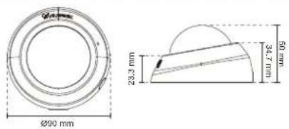
Compatible Accessories
PoE Kits

POE-IJ-1748NDN
802.3af Compliant PoE Injector
All specifications are subject to change without notice. Copyright © 2013 VIVOTEK INC. All rights reserved.
Distributed by:

VIVOTEK INC.
6F. No.192. Lien-Cheng Rd., Chung-Ho, New Taipei City, 235, Taiwan, R.O.C.
T: +886-2-82455782 | E: +886-2-82455537 | E: sales@vivntak.com
VIVOTEK USA, INC.
2050 Ringwood Avenue, San Jose, CA 95131
T: 408-773-8650 | F: 408-773-8298 | E: salesues@yivotek.com
Ver 1.0
Technology License Notice
MPEG-4 AAC Technology
THIS PRODUCT IS LICENSED UNDER THE MPEG-4 AAC AUDIO PATENT LICENSE. THIS PRODUCT MAY NOT BE DECOMPILED, REVERSE-ENGINEERED OR COPIED, EXCEPT WITH REGARD TO PC SOFTWARE, OF WHICH YOU MAY MAKE SINGLE COPIES FOR ARCHIVAL PURPOSES. FOR MORE INFORMATION, PLEASE REFER TO HTTP://WWW.VIALICENSING.COM.
MPEG-4 Visual Technology
THIS PRODUCT IS LICENSED UNDER THE MPEG-4 VISUAL PATENT PORTFOLIO LICENSE FOR THE PERSONAL AND NON-COMMERCIAL USE OF A CONSUMER FOR (i) ENCODING VIDEO IN COMPLIANCE WITH THE MPEG-4 VISUAL STANDARD ("MPEG-4 VIDEO") AND/OR (ii) DECODING MPEG-4 VIDEO THAT WAS ENCODED BY A CONSUMER ENGAGED IN A PERSONAL AND NON-COMMERCIAL ACTIVITY AND/OR WAS OBTAINED FROM A VIDEO PROVIDER LICENSED BY MPEG LA TO PROVIDE MPEG-4 VIDEO. NO LICENSE IS GRANTED OR SHALL BE IMPLIED FOR ANY OTHER USE. ADDITIONAL INFORMATION INCLUDING THAT RELATING TO PROMOTIONAL, INTERNAL AND COMMERCIAL USES AND LICENSING MAY BE OBTAINED FROM MPEG LA, LLC. PLEASE REFER TO HTTP://WWW.MPEGLA.COM.
AMR-NB Standard
THIS PRODUCT IS LICENSED UNDER THE AMR-NB STANDARD PATENT LICENSE AGREEMENT. WITH RESPECT TO THE USE OF THIS PRODUCT, THE FOLLOWING LICENSORS' PATENTS MAY APPLY:
TELEFONAKIEBOLAGET ERICSSON AB: US PAT. 6192335; 6275798; 6029125; 6424938; 6058359. NOKIA CORPORATION: US PAT. 5946651; 6199035. VOICEAGE CORPORATION: AT PAT. 0516621; BE PAT. 0516621; CA PAT. 2010830; CH PAT. 0516621; DE PAT. 0516621; DK PAT. 0516621; ES PAT. 0516621; FR PAT. 0516621; GB PAT. 0516621; GR PAT. 0516621; IT PAT. 0516621; LI PAT. 0516621; LU PAT. 0516621; NL PAT. 0516621; SE PAT 0516621; US PAT 5444816; AT PAT. 819303/AT E 198805T1; AU PAT. 697256; BE PAT. 819303; BR PAT. 9604838-7; CA PAT. 2216315; CH PAT. 819303; CN PAT. ZL96193827.7; DE PAT. 819303/DE69611607T2; DK PAT. 819303; ES PAT. 819303; EP PAT. 819303; FR PAT. 819303; GB PAT. 819303; IT PAT. 819303; JP PAT. APP. 8-529817; NL PAT. 819303; SE PAT. 819303; US PAT. 5664053. THE LIST MAY BE UPDATED FROM TIME TO TIME BY LICENSORS AND A CURRENT VERSION OF WHICH IS AVAILABLE ON LICENSOR'S WEBSITE AT HTTP://WWW.VOICEAGE.COM.
Electromagnetic Compatibility (EMC)
FCC Statement
This device compiles with FCC Rules Part 15. Operation is subject to the following two conditions.
■ This device may not cause harmful interference, and
■ This device must accept any interference received, including interference that may cause undesired operation.
This equipment has been tested and found to comply with the limits for a Class B digital device, pursuant to Part 15 of the FCC Rules. These limits are designed to provide reasonable protection against harmful interference in a residential installation. This equipment generates, uses and can radiate radio frequency energy and, if not installed and used in accordance with the instructions, may cause harmful interference to radio communications. However, there is no guarantee that interference will not occur in a partial installation. If this equipment does cause harmful interference to radio or television reception, which can be determined by turning the equipment off and on, the user is encouraged to try to correct the interference by one or more of the following measures:
■ Reorient or relocate the receiving antenna.
■ Increase the separation between the equipment and receiver.
■ Connect the equipment into an outlet on a circuit different from that to which the receiver is connected.
■ Consult the dealer or an experienced radio/TV technician for help.
Shielded interface cables must be used in order to comply with emission limits.
CE Mark Warning
This is a Class B product. In a domestic environment, this product may cause radio interference, in which case the user may be required to take adequate measures.
VCCI Warning
VIVOTEK Inc. cannot be held responsible for any technical or typographical errors and reserves the right to make changes to the product and manuals without prior notice. VIVOTEK Inc. makes no warranty of any kind with regard to the material contained within this document, including, but not limited to, the implied warranties of merchantability and fitness for any particular purpose.
- Table of Contents
- Overview......4
- Main Page 22
- Client Settings 27
- Configuration....31
- Appendix 117
- Overview
- Revision History
- Read Before Use
- Package Contents
- Symbols and Statements in this Document
- Physical Description
- Outer View
- Digital Input Diagram
- Micro SD/SDHC Card Capacity
- Installation
- Removing Dome Cover
- IMPORTANT!
- NOTE:
- Mounting the Network Camera - Ceiling or Wall Mount
- LED Definitions
- Network Deployment
- General Connection (without PoE)
- Power over Ethernet (PoE)
- When using a PoE-enabled switch
- When using a non-PoE switch
- Internet connection via a router
- Internet connection with static IP
- Internet connection via PPPoE (Point-to-Point over Ethernet)
- Software Installation
- Ready to Use
- Adjusting the Lens
- WARNING!
- Accessing the Network Camera
- Using Web Browsers
- Tips
- Using RTSP Players
- Using 3GPP-compatible Mobile Devices
- Using VIVOTEK Recording Software
- Main Page
- VIVOTEK INC. Logo
- Host Name
- Camera Control Area
- Configuration Area
- Hide Button
- Resize Buttons
- Live Video Window
- Go to
- Client Settings
- H.264 Media Options
- H.264 Protocol Options
- MP4 Saving Options
- Local Streaming Buffer Time
- Joystick settings
- Enable Joystick
- Buttons Configuration
- Configuration
- Basic Mode
- Advanced Mode
- System > General settings
- System
- System time
- System > Homepage layout Advanced Mode
- General settings
- Logo graph
- Customized button
- Theme Options
- System > Logs Advanced Mode
- Log server settings
- System log
- Access log
- System log Access log
- System > Parameters Advanced Mode
- System > Maintenance
- General settings > Upgrade firmware
- General settings > Reboot
- General settings > Restore
- Restore
- Import/Export files
- Export files
- Upload files
- Media > Image
- Image settings
- Image Adjustment
- Exposure Advanced Mode
- Exposure control:
- Privacy mask
- Media > Video
- Stream settings
- Medi: Video NOTE:
- ■ Frame size
- ■ Maximum frame rate
- ■ Intra frame period
- ■ Video quality
- Constant bit rate:
- Media > Audio Advanced Mode
- Audio Settings
- Audio type: Advanced Mode.
- Network > General settings
- Network Type
- LAN
- PPPoE (Point-to-point over Ethernet)
- Enable IPv6
- Refers to Ethernet
- IPv6 information
- Port
- Network > Streaming protocols
- HTTP streaming
- RTSP Streaming
- Network > DDNS
- Express link
- Manual setup
- ■ Safe100.net
- Register
- ■ CustomSafe100
- Network > QoS (Quality of Service) Advanced Mode
- Requirements for QoS
- QoS models
- CoS (the VLAN 802.1p model)
- QoS/DSCP (the DiffServ model)
- Network > SNMP (Simple Network Management Protocol)
- SNMP Configuration
- Enable SNMPv1, SNMPv2c
- Enable SNMPv3
- Security > User Account
- Root Password
- Privilege Management
- Account Management
- Security > HTTPS (Hypertext Transfer Protocol over SSL)
- Create and Install Certificate Method
- Create self-signed certificate
- Create certificate request and install
- Enable HTTPS
- Security > Access List Advanced Mode
- Filter
- Administrator IP address
- Security > IEEE 802.1X Advanced Mode
- IEEE 802.1x
- Enable 802.1x
- EAP-TLS
- PTZ > PTZ settings
- Home page in E-PTZ Mode
- Global View
- Moving Instantly
- Click on Image
- Patrol settings
- Home page in the e-PTZ Mode
- Event > Event settings
- Event
- Schedule
- Trigger
- ■ Camera tampering detection
- ■ Manual Trigger
- Action
- ■ Backup media if the network is disconnected
- Add server
- Server type - Email
- Server type - FTP
- ■ Passive mode
- Server type - HTTP
- Network storage:
- The format is: HH (24r)
- The format is: File name prefix + Minute (mm)
- Add media
- Media type - Snapshot
- Media type - Video clip
- Media type - System log
- Customized Script
- Applications > Motion detection
- For example:
- >Motion detection profile settings
- Applications > Digital Input
- Applications > Tampering detection
- Recording > Recording settings Advanced Mode
- Recording Settings
- Trigger
- Destination
- NAS server
- Recording file management
- Local storage > SD card management Advanced Mode
- SD card staus
- SD card control
- Local storage > Content management
- Searching and Viewing the Records
- Search Results
- Appendix
- URL Commands for the Network Camera
- Overview
- Style Convention
- General CGI URL Syntax and Parameters
- Security Level
- Get Server Parameter Values
- Set Server Parameter Values
- Available parameters on the server
- system
- system.info
- status
- digital input behavior define
- security
- network
- 802.1x
- QOS
- IPV6
- FTP
- HTTP
- HTTPS port
- RTSP
- RTSP multicast
- RTP port
- PPPoE
- ipfilter
- video input
- video input setting per channel
- Alternative video input profiles per channel
- video input preview
- image setting per channel
- image setting for preview
- Audio input per channel
- Time Shift settings
- Motion detection settings
- Tampering detection settings
- DDNS
- Express link
- UPnP presentation
- UPnP port forwarding
- System log
- SNMP
- Privacy mask
- Capability
- Customized event script
- Event setting
- Server setting for event action
- Media setting for event action
- Recording
- HTTPS
- Storage management setting
- Region of interest
- ePTZ setting
- Useful Functions
- Query Status of the Digital Input
- Capture Single Snapshot
- Account Management
- System Logs
- Upgrade Firmware
- ePTZ Camera Control
- ePTZ Recall
- ePTZ Preset Locations
- IP Filtering
- IP Filtering for ONVIF
- Event/Control HTTP Tunnel Channel
- Get SDP of Streams
- Open the Network Stream
- Storage managements (capability.storage.dbenabled > 0)
- Return Message
- Virtual input
- Open Timeshift Stream
- Open Anystream
- Export Files
- Upload Files
- Technical Specifications
- Compatible Accessories
- Technology License Notice
- MPEG-4 AAC Technology
- MPEG-4 Visual Technology
- AMR-NB Standard
- Electromagnetic Compatibility (EMC)
- FCC Statement
- CE Mark Warning
- VCCI Warning
Brand : Vivotek
Model : FD8166-F6
Category : Security Camera